Embed Size (px)
Citation preview
ASV Stübbe GmbH & Co. KGHollwieser Straße 5 · 32602 Vlotho, GermanyPhone: +49 (0) 5733-799-0 · Fax: +49 (0) 5733-799-5000Email: [email protected] · Internet: www.asv-stuebbe.com
We reserve the right to make technical changes.Issue 2016.03.21-en
Print No. 300174TR MA DE Rev002
Ball valve C 200Nominal size DN 10–50Nominal size 3/8“–2“Nominal pressure PN 10–16 bar
Additional options on request • Silicone free
www.asv-stuebbe.com/products/valves
PVC-U PP PVDF
C 200
C 200 with relief well
Characteristics, C 200 with relief well • Like characteristics of C200 • The relief well prevents pressure from being built up due to the medium in the ball of the closed valve unit
• For medium types prone to gas emission, e.g. H2O2, NaOCl
• Product range differing from C 200, see pictograph
Characteristics C 200 • High-quality industrial valve • Flexible modular system with wide range of variants • Reliable material combinations for safe handling of critical medium types
• Newly designed ergonomic grip with position lock "Safety Guard"
• Intelligent accessories and interfaces for integration of limit switches and actuators
• Optional relief well for medium types prone to gas emission
• Integrated mounting bushing
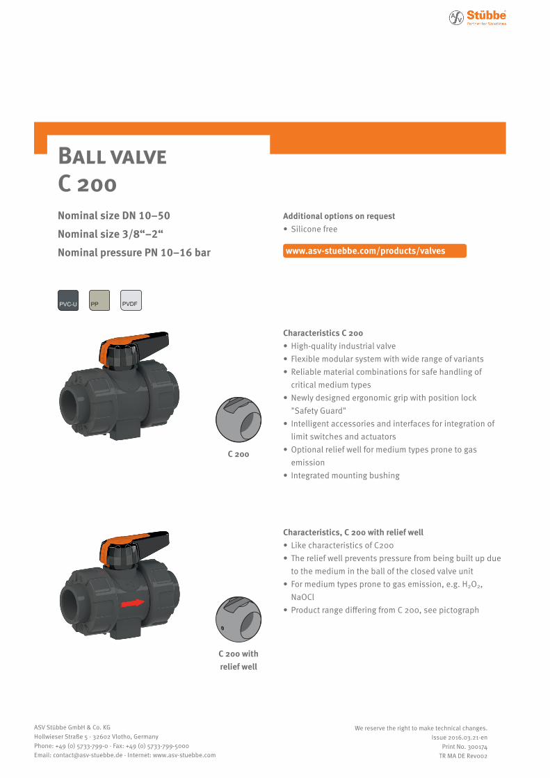
Pictogram Ball valve C 200
2
ASV Stübbe GmbH & Co. KGHollwieser Straße 5 · 32602 Vlotho, GermanyPhone: +49 (0) 5733-799-0 · Fax: +49 (0) 5733-799-5000Email: [email protected] · Internet: www.asv-stuebbe.com
We reserve the right to make technical changes.Issue 2016.03.21-en
Print No. 300174TR MA DE Rev002
pneumaticmanual electric
Seal
Actuator
EPDM
FPM
Connection
Socket
Spigot
Flange
Thread
availablenot available
Basic nominal diameters:
DN 8 DN 10 DN 15 DN 20 DN 25 DN 32 DN 40 DN 50 DN 65 DN 80 DN 100 DN 125 DN 150 DN 200 DN 250 DN 300 DN 350 DN 400
Connection material (pipe connection)
* incl. DN 10
PVC-U: socket DIN*Socket ANSI, BS, JISFemale thread Rp
1.4571 female thread RpMale thread R
2.0401 female thread RpMale thread R
PP socket DIN*Female thread Rp
PVDF socket DIN*
PE spigot (90 mm)
PP spigot IRPE spigot (90 mm)
PVDF spigot IR
PP/St. flange ANSIGFR flange DIN
PP/st. flange DIN, ANSI
PPPVC-U PVDF
1 2 3
4 5 6
7 7 8
1
2
3
4
5
6
7
8
Thread
On request» silicone free
C 200
Options
… Makes: Valpes l (J&J)
… Wide-range voltage ranges:15 – 30 V AC/DC100 – 240 V AC/DC
… Heating
… Failsafe
Options
… Makes: Prisma l (Air Torque)
… Control functions:NC l NO l DA
… Limit switches:Micro switchesproximity switches
… Pilot valves:24 V l 230 V
Options
… Limit switch:Micro switchesproximity switches
NC = normally closedNO = normally openDA = double acting
3
ASV Stübbe GmbH & Co. KGHollwieser Straße 5 · 32602 Vlotho, GermanyPhone: +49 (0) 5733-799-0 · Fax: +49 (0) 5733-799-5000Email: [email protected] · Internet: www.asv-stuebbe.com
We reserve the right to make technical changes.Issue 2016.03.21-en
Print No. 300174TR MA DE Rev002
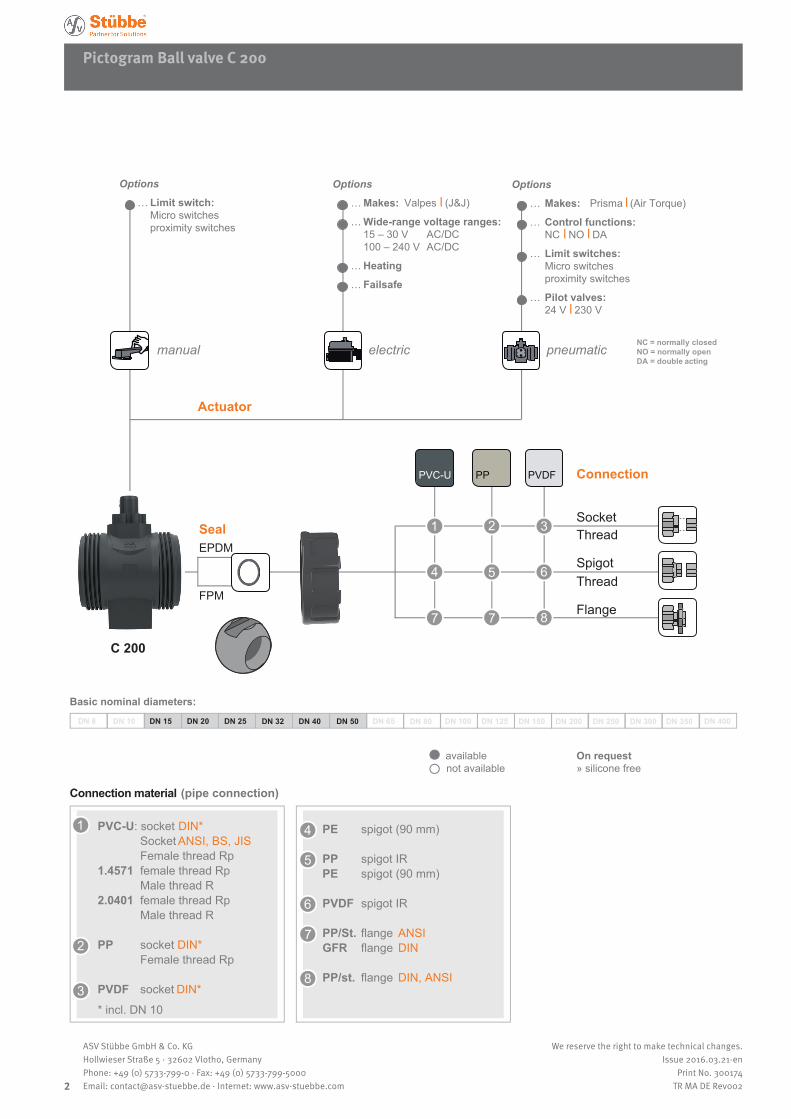
Pictogra Ball valve C 200 with relief well
pneumaticmanual electric
Seal
Actuator
FPM
Connection
Socket
Spigot
Flange
Thread
availablenot available
Basic nominal diameters:
DN 8 DN 10 DN 15 DN 20 DN 25 DN 32 DN 40 DN 50 DN 65 DN 80 DN 100 DN 125 DN 150 DN 200 DN 250 DN 300 DN 350 DN 400
Connection material (pipe connection)
* incl. DN 10
PVC-U socket DIN*Socket ANSI, BS, JISFemale thread Rp
1.4571 female thread RpMale thread R
PE spigot (90 mm)
PP/St. flange ANSIGFR flange DIN
PVC-U
1
2
3
1
2
Thread
3
On request» silicone free
C 200 with relief well
NC = normally closedNO = normally openDA = double acting
Options
… Makes: Valpes l (J&J)
… Wide-range voltage ranges:15 – 30 V AC/DC100 – 240 V AC/DC
… Heating
… Failsafe
Options
… Makes: Prisma l (Air Torque)
… Control functions:NC l NO l DA
… Limit switch:Micro switchesproximity switches
… Pilot valves:24 V l 230 V
Options
… Limit switch:Micro switchesproximity switches
Ball valve C 200
4
ASV Stübbe GmbH & Co. KGHollwieser Straße 5 · 32602 Vlotho, GermanyPhone: +49 (0) 5733-799-0 · Fax: +49 (0) 5733-799-5000Email: [email protected] · Internet: www.asv-stuebbe.com
We reserve the right to make technical changes.Issue 2016.03.21-en
Print No. 300174TR MA DE Rev002
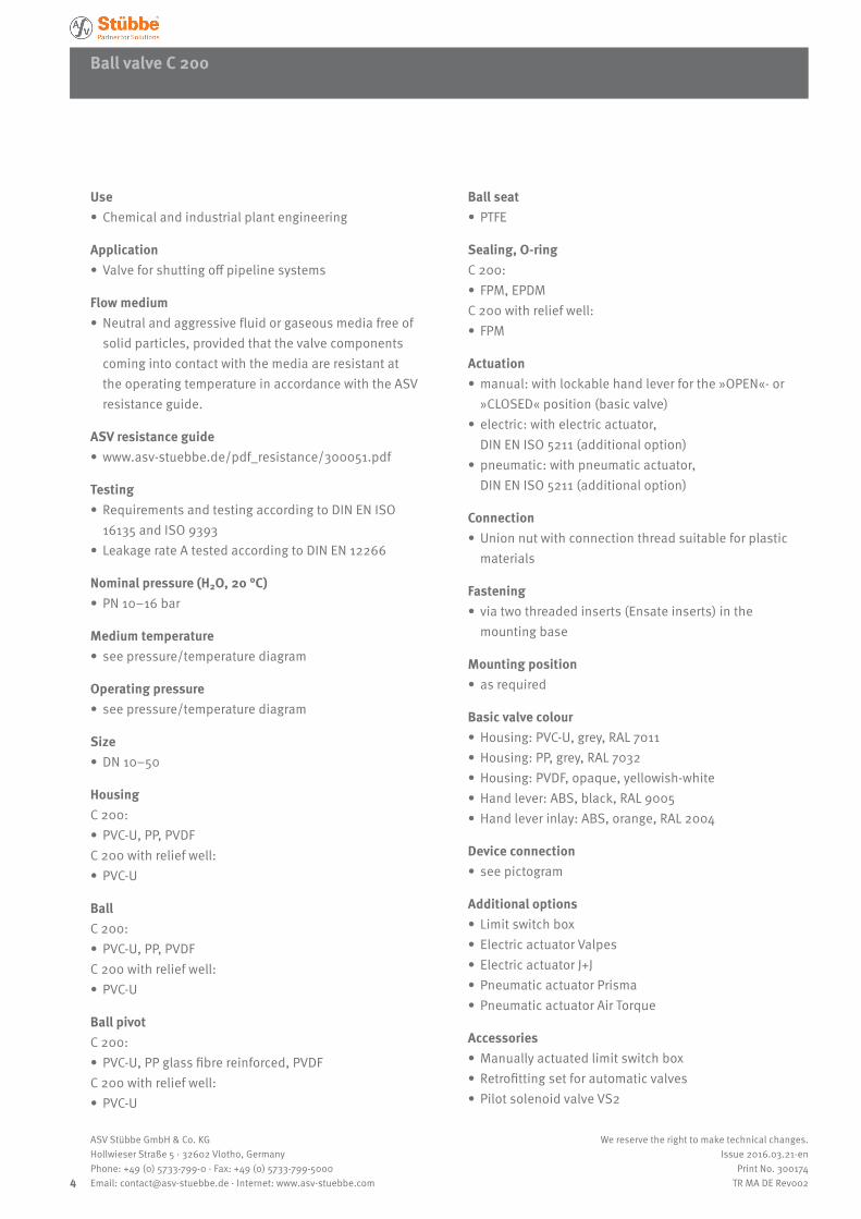
Use • Chemical and industrial plant engineering
Application • Valve for shutting off pipeline systems
Flow medium • Neutral and aggressive fluid or gaseous media free of solid particles, provided that the valve components coming into contact with the media are resistant at the operating temperature in accordance with the ASV resistance guide.
ASV resistance guide • www.asv-stuebbe.de/pdf_resistance/300051.pdf
Testing • Requirements and testing according to DIN EN ISO 16135 and ISO 9393
• Leakage rate A tested according to DIN EN 12266
Nominal pressure (H2O, 20 °C) • PN 10–16 bar
Medium temperature • see pressure/temperature diagram
Operating pressure • see pressure/temperature diagram
Size • DN 10–50
HousingC 200:
• PVC-U, PP, PVDFC 200 with relief well:
• PVC-U
BallC 200:
• PVC-U, PP, PVDFC 200 with relief well:
• PVC-U
Ball pivotC 200:
• PVC-U, PP glass fibre reinforced, PVDFC 200 with relief well:
• PVC-U
Ball seat • PTFE
Sealing, O-ringC 200:
• FPM, EPDMC 200 with relief well:
• FPM
Actuation • manual: with lockable hand lever for the »OPEN«- or »CLOSED« position (basic valve)
• electric: with electric actuator, DIN EN ISO 5211 (additional option)
• pneumatic: with pneumatic actuator, DIN EN ISO 5211 (additional option)
Connection • Union nut with connection thread suitable for plastic materials
Fastening • via two threaded inserts (Ensate inserts) in the mounting base
Mounting position • as required
Basic valve colour • Housing: PVC-U, grey, RAL 7011 • Housing: PP, grey, RAL 7032 • Housing: PVDF, opaque, yellowish-white • Hand lever: ABS, black, RAL 9005 • Hand lever inlay: ABS, orange, RAL 2004
Device connection • see pictogram
Additional options • Limit switch box • Electric actuator Valpes • Electric actuator J+J • Pneumatic actuator Prisma • Pneumatic actuator Air Torque
Accessories • Manually actuated limit switch box • Retrofitting set for automatic valves • Pilot solenoid valve VS2
Ball valve C 200
5
ASV Stübbe GmbH & Co. KGHollwieser Straße 5 · 32602 Vlotho, GermanyPhone: +49 (0) 5733-799-0 · Fax: +49 (0) 5733-799-5000Email: [email protected] · Internet: www.asv-stuebbe.com
We reserve the right to make technical changes.Issue 2016.03.21-en
Print No. 300174TR MA DE Rev002
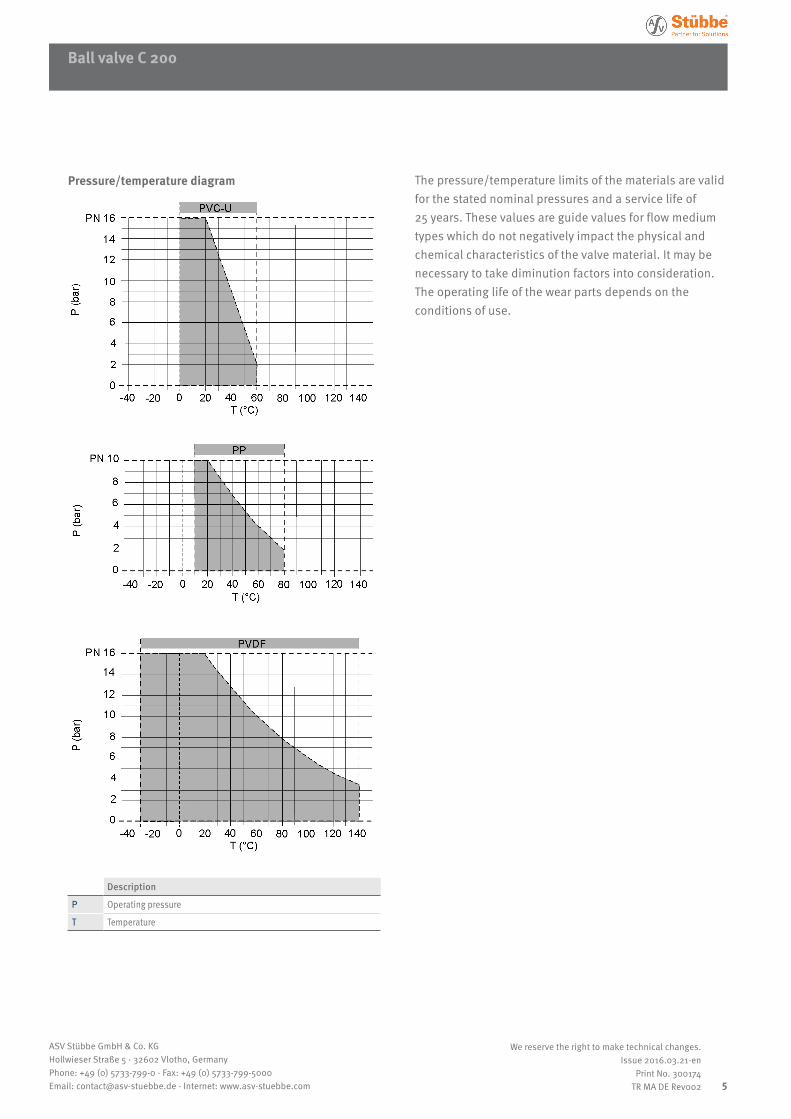
Pressure/temperature diagram
Description
P Operating pressure
T Temperature
The pressure/temperature limits of the materials are valid for the stated nominal pressures and a service life of 25 years. These values are guide values for flow medium types which do not negatively impact the physical and chemical characteristics of the valve material. It may be necessary to take diminution factors into consideration.The operating life of the wear parts depends on the conditions of use.
Ball valve C 200
6
ASV Stübbe GmbH & Co. KGHollwieser Straße 5 · 32602 Vlotho, GermanyPhone: +49 (0) 5733-799-0 · Fax: +49 (0) 5733-799-5000Email: [email protected] · Internet: www.asv-stuebbe.com
We reserve the right to make technical changes.Issue 2016.03.21-en
Print No. 300174TR MA DE Rev002
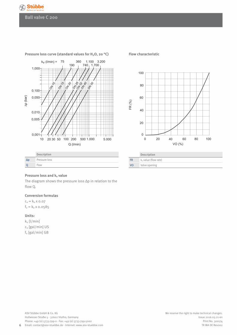
Pressure loss curve (standard values for H2O, 20 °C)
190360
7401.100
1.7003.200
1,000
0,100
0,050
0,010
0,005
0,001
kv (l/min) = 75
10 20 30 50 100 200 500 1.000 5.000
∆p (b
ar)
Q (l/min)
DN 1
0
DN 1
5DN
20
DN 2
5DN
32
DN 4
0DN
50
Description
Δp Pressure loss
Q Flow
Pressure loss and kv valueThe diagram shows the pressure loss Δp in relation to the flow Q.
Conversion formulascv = kv x 0.07fv = kv x 0.0585
Units:kv [l/min]cv [gal/min] USfv [gal/min] GB
Flow characteristic
100
80
60
40
20
0100 80 60 40 20 0
VO (%)
FR (%
)
Description
FR kv value (flow rate)
VO Valve opening
7
ASV Stübbe GmbH & Co. KGHollwieser Straße 5 · 32602 Vlotho, GermanyPhone: +49 (0) 5733-799-0 · Fax: +49 (0) 5733-799-5000Email: [email protected] · Internet: www.asv-stuebbe.com
We reserve the right to make technical changes.Issue 2016.03.21-en
Print No. 300174TR MA DE Rev002
Ball valve C 200with hand lever
h
v M
H
L2
L1L3
Rp
E
D1R
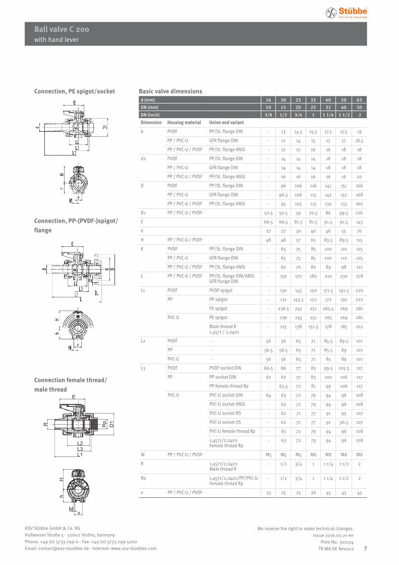
Connection, PE spigot/socket
Connection, PP-(PVDF-)spigot/ flange
Connection female thread/ male thread
Basic valve dimensionsd (mm) 16 20 25 32 40 50 63DN (mm) 10 15 20 25 32 40 50DN (inch) 3/8 1/2 3/4 1 1 1/4 1 1/2 2Dimension Housing material Union end variant
b PVDF PP/St. flange DIN - 13 14.5 15.5 17.5 17.5 19
PP / PVC-U GFR flange DIN - 12 14 15 17 17 18.5
PP / PVC-U / PVDF PP/St. flange ANSI - 12 12 16 16 18 18
d2 PVDF PP/St. flange DIN - 14 14 14 18 18 18
PP / PVC-U GFR flange DIN - 14 14 14 18 18 18
PP / PVC-U / PVDF PP/St. flange ANSI - 16 16 16 16 16 20
D PVDF PP/St. flange DIN - 96 106 116 141 151 166
PP / PVC-U GFR flange DIN - 96.5 106 115 142 152 168
PP / PVC-U / PVDF PP/St. flange ANSI - 95 105 113 130 133 160
D1 PP / PVC-U / PVDF 50.5 50.5 59 70.5 86 99.5 126
E 66.5 66.5 81.5 81.5 91.5 91.5 143
h 27 27 30 40 46 55 70
H PP / PVC-U / PVDF 48 48 57 65 83.5 89.5 115
K PVDF PP/St. flange DIN - 65 75 85 100 110 125
PP / PVC-U GFR flange DIN - 65 75 85 100 110 125
PP / PVC-U / PVDF PP/St. flange ANSI - 60 70 80 89 98 121
L PP / PVC-U / PVDF PP/St. flange DIN/ANSIGFR flange DIN
- 150 170 180 210 230 278
L1 PVDF PVDF spigot - 130 143 150 171.5 191.5 220
PP PP spigot - 131 143.5 152 172 192 222
PE spigot - 236.5 245 251 265.5 269 281
PVC-U PE spigot - 236 245 251 265 269 281
Male thread R 1,4571 / 2,0401
- 125 138 151.5 178 185 212
L2 PVDF - 56 56 65 71 85.5 89.5 101
PP - 56.5 56.5 65 71 85.5 89 101
PVC-U - 56 56 65 71 85 89 101
L3 PVDF PVDF socket DIN 66.5 66 77 83 99.5 105.5 117
PP PP socket DIN 67 67 77 83 100 106 117
PP female thread Rp - 63.5 72 81 99 106 117
PVC-U PVC-U socket DIN 64 63 72 79 94 96 108
PVC-U socket ANSI - 63 72 79 94 96 108
PVC-U socket BS - 62 71 77 91 95 107
PVC-U socket JIS - 62 71 77 91 96.5 107
PVC-U female thread Rp - 63 72 79 94 96 108
1,4571/2,0401- Female thread Rp
- 63 72 79 94 96 108
M PP / PVC-U / PVDF M5 M5 M5 M6 M8 M8 M8
R 1,4571/2,0401- Male thread R
- 1/2 3/4 1 1 1/4 1 1/2 2
Rp 1,4571/2,0401/PP/PVC-U-Female thread Rp
- 1/2 3/4 1 1 1/4 1 1/2 2
v PP / PVC-U / PVDF 25 25 25 26 45 45 45
with hand lever
8
ASV Stübbe GmbH & Co. KGHollwieser Straße 5 · 32602 Vlotho, GermanyPhone: +49 (0) 5733-799-0 · Fax: +49 (0) 5733-799-5000Email: [email protected] · Internet: www.asv-stuebbe.com
We reserve the right to make technical changes.Issue 2016.03.21-en
Print No. 300174TR MA DE Rev002
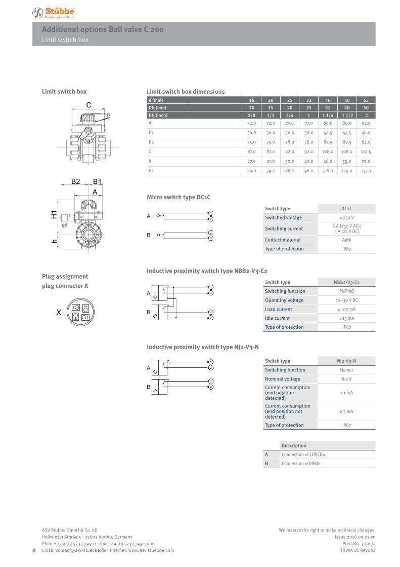
Additional options Ball valve C 200 Limit switch box
12
3
4
X
C
H1
h
AB2 B1
Limit switch box
Limit switch box
Plug assignment plug connector X
Limit switch box dimensionsd (mm) 16 20 25 32 40 50 63DN (mm) 10 15 20 25 32 40 50DN (inch) 3/8 1/2 3/4 1 1 1/4 1 1/2 2A 72.0 72.0 77.0 77.0 89.0 89.0 92.5
B1 36.0 36.0 38.0 38.0 44.5 44.5 46.0
B2 75.0 75.0 78.0 78.0 82.5 82.5 84.0
C 87.0 87.0 92.0 92.0 108.0 108.0 112.5
h 27.0 27.0 30.0 40.0 46.0 55.0 70.0
H1 79.0 79.0 88.0 96.0 118.0 124.0 157.0
Description
A Connection »CLOSED«
B Connection »OPEN«
Switch type DC1C
Switched voltage ≤ 250 V
Switching current 6 A (250 V AC); 3 A (24 V DC)
Contact material AgNi
Type of protection IP67
Micro switch type DC1C
A
B
Switch type NBB2-V3-E2
Switching function PNP NO
Operating voltage 10–30 V DC
Load current ≤ 100 mA
Idle current ≤ 15 mA
Type of protection IP67
Inductive proximity switch type NBB2-V3-E2
A
B
Inductive proximity switch type NJ2-V3-N
A
B
Switch type NJ2-V3-N
Switching function Namur
Nominal voltage 8.2 VCurrent consumption (end position detected)
≤ 1 mA
Current consumption (end position not detected)
≥ 3 mA
Type of protection IP67
9
ASV Stübbe GmbH & Co. KGHollwieser Straße 5 · 32602 Vlotho, GermanyPhone: +49 (0) 5733-799-0 · Fax: +49 (0) 5733-799-5000Email: [email protected] · Internet: www.asv-stuebbe.com
We reserve the right to make technical changes.Issue 2016.03.21-en
Print No. 300174TR MA DE Rev002
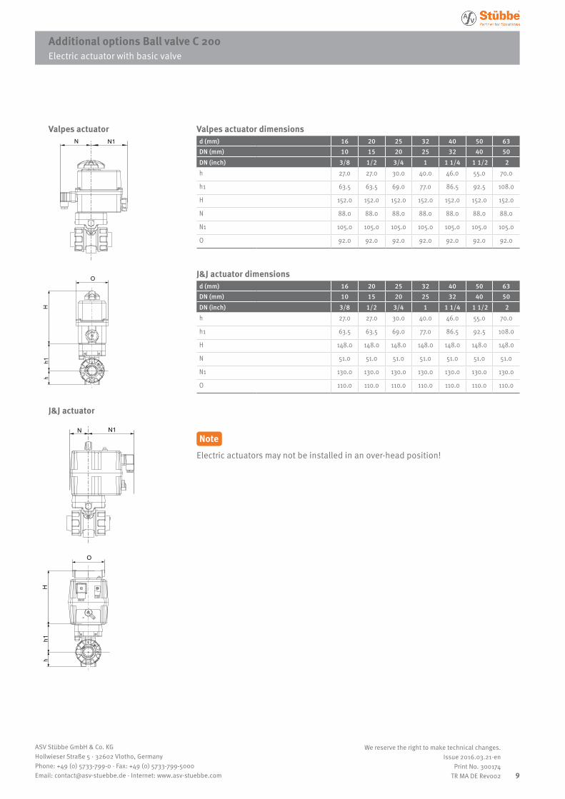
Additional options Ball valve C 200 Electric actuator with basic valve
Valpes actuator dimensionsd (mm) 16 20 25 32 40 50 63DN (mm) 10 15 20 25 32 40 50DN (inch) 3/8 1/2 3/4 1 1 1/4 1 1/2 2h 27.0 27.0 30.0 40.0 46.0 55.0 70.0
h1 63.5 63.5 69.0 77.0 86.5 92.5 108.0
H 152.0 152.0 152.0 152.0 152.0 152.0 152.0
N 88.0 88.0 88.0 88.0 88.0 88.0 88.0
N1 105.0 105.0 105.0 105.0 105.0 105.0 105.0
O 92.0 92.0 92.0 92.0 92.0 92.0 92.0
J&J actuator dimensionsd (mm) 16 20 25 32 40 50 63DN (mm) 10 15 20 25 32 40 50DN (inch) 3/8 1/2 3/4 1 1 1/4 1 1/2 2h 27.0 27.0 30.0 40.0 46.0 55.0 70.0
h1 63.5 63.5 69.0 77.0 86.5 92.5 108.0
H 148.0 148.0 148.0 148.0 148.0 148.0 148.0
N 51.0 51.0 51.0 51.0 51.0 51.0 51.0
N1 130.0 130.0 130.0 130.0 130.0 130.0 130.0
O 110.0 110.0 110.0 110.0 110.0 110.0 110.0
N N1
O
Hh1
h
N N1
O
Hh1
h
Electric actuator with basic valve
Valpes actuator
J&J actuator
NoteElectric actuators may not be installed in an over-head position!
10
ASV Stübbe GmbH & Co. KGHollwieser Straße 5 · 32602 Vlotho, GermanyPhone: +49 (0) 5733-799-0 · Fax: +49 (0) 5733-799-5000Email: [email protected] · Internet: www.asv-stuebbe.com
We reserve the right to make technical changes.Issue 2016.03.21-en
Print No. 300174TR MA DE Rev002
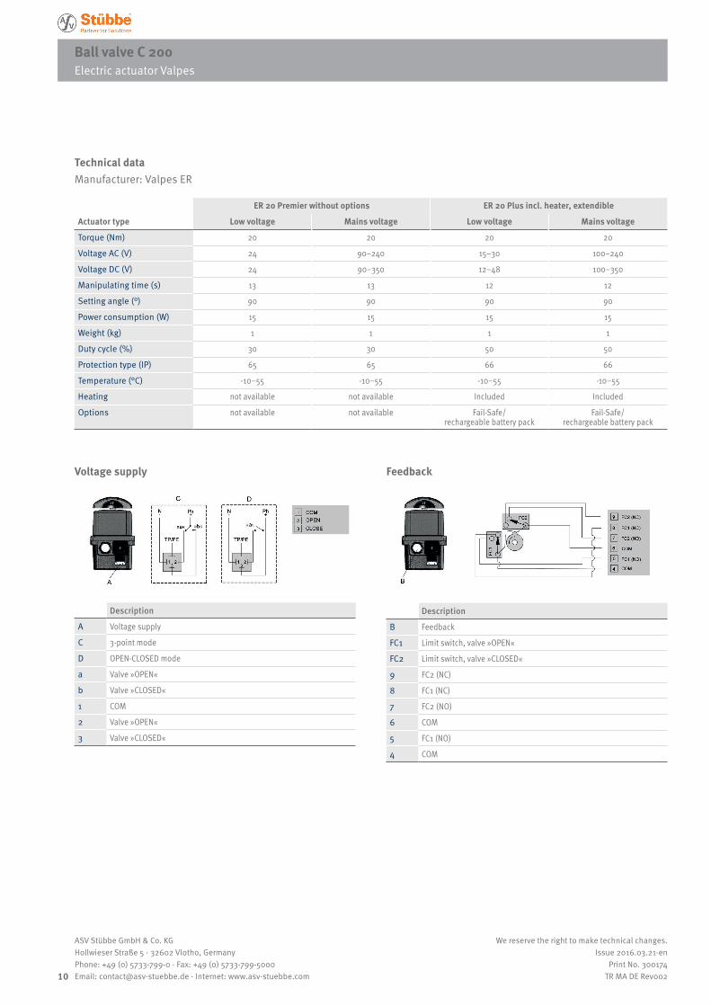
Ball valve C 200Electric actuator Valpes
Technical dataManufacturer: Valpes ER
ER 20 Premier without options ER 20 Plus incl. heater, extendible
Actuator type Low voltage Mains voltage Low voltage Mains voltage
Torque (Nm) 20 20 20 20
Voltage AC (V) 24 90–240 15–30 100–240
Voltage DC (V) 24 90–350 12–48 100–350
Manipulating time (s) 13 13 12 12
Setting angle (°) 90 90 90 90
Power consumption (W) 15 15 15 15
Weight (kg) 1 1 1 1
Duty cycle (%) 30 30 50 50
Protection type (IP) 65 65 66 66
Temperature (°C) -10–55 -10–55 -10–55 -10–55
Heating not available not available Included Included
Options not available not available Fail-Safe/ rechargeable battery pack
Fail-Safe/ rechargeable battery pack
Electric actuator Valpes
Voltage supply
Description
A Voltage supply
C 3-point mode
D OPEN-CLOSED mode
a Valve »OPEN«
b Valve »CLOSED«
1 COM
2 Valve »OPEN«
3 Valve »CLOSED«
Feedback
Description
B Feedback
FC1 Limit switch, valve »OPEN«
FC2 Limit switch, valve »CLOSED«
9 FC2 (NC)
8 FC1 (NC)
7 FC2 (NO)
6 COM
5 FC1 (NO)
4 COM
11
ASV Stübbe GmbH & Co. KGHollwieser Straße 5 · 32602 Vlotho, GermanyPhone: +49 (0) 5733-799-0 · Fax: +49 (0) 5733-799-5000Email: [email protected] · Internet: www.asv-stuebbe.com
We reserve the right to make technical changes.Issue 2016.03.21-en
Print No. 300174TR MA DE Rev002
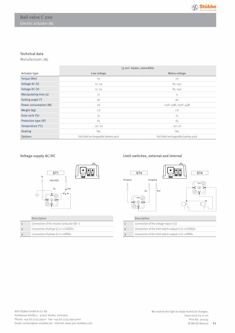
Ball valve C 200Electric actuator J&J
Technical dataManufacturer: J&J
J3 incl. heater, extendible
Actuator type Low voltage Mains voltage
Torque (Nm) 20 20
Voltage AC (V) 12–24 85–240
Voltage DC (V) 12–24 85–240
Manipulating time (s) 12 11
Setting angle (°) 90 90
Power consumption (W) 26 110V–19W; 230V–44W
Weight (kg) 1.8 1.8
Duty cycle (%) 75 75
Protection type (IP) 65 65
Temperature (°C) -20–70 -20–70
Heating Yes Yes
Options Fail-Safe/rechargeable battery pack Fail-Safe/rechargeable battery pack
Electric actuator J&J
Voltage supply AC/DC
N-
L+
Zu Auf
1 213
VAC/VDC
L+
Eingang Ausgang
L+
L+
Zu Auf
213
ST1 ST4 ST4ST1
ST3 ST4ST1
ST3 ST4
Description
1 Connection of the neutral conductor (N/–)
2 Connection of phase (L/+) »CLOSED«
3 Connection of phase (L/+) »OPEN«
Limit switches, external and internal
N-
L+
Zu Auf
1 213
VAC/VDC
L+
Eingang Ausgang
L+
L+
Zu Auf
213
ST1 ST4 ST4ST1
ST3 ST4ST1
ST3 ST4
Description
1 Connection of the voltage input (+/L)
2 Connection of the limit switch output (+/L) »CLOSED«
3 Connection of the limit switch output (+/L) »OPEN«
12
ASV Stübbe GmbH & Co. KGHollwieser Straße 5 · 32602 Vlotho, GermanyPhone: +49 (0) 5733-799-0 · Fax: +49 (0) 5733-799-5000Email: [email protected] · Internet: www.asv-stuebbe.com
We reserve the right to make technical changes.Issue 2016.03.21-en
Print No. 300174TR MA DE Rev002
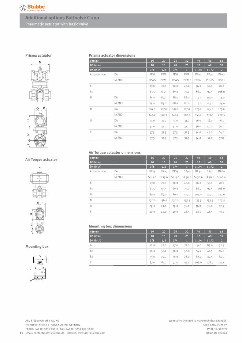
Additional options Ball valve C 200 Pneumatic actuator with basic valve
Prisma actuator dimensionsd (mm) 16 20 25 32 40 50 63DN (mm) 10 15 20 25 32 40 50DN (inch) 3/8 1/2 3/4 1 1 1/4 1 1/2 2Actuator type DA PPW PPW PPW PPW PP00 PP00 PP00
NC/NO PPWS PPWS PPWS PPWS PP00S PP10S PP10S
h 27.0 27.0 30.0 40.0 46.0 55.0 70.0
h1 63.5 63.5 69.0 77.0 86.5 92.5 108.0
H DA 85.0 85.0 88.0 88.0 114.0 114.0 114.0
NC/NO 85.0 85.0 88.0 88.0 114.0 123.0 123.0
N DA 107.0 107.0 107.0 107.0 125.0 125.0 125.0
NC/NO 142.0 142.0 142.0 142.0 155.0 230.5 230.5
O DA 31.0 31.0 31.0 31.0 36.0 36.0 36.0
NC/NO 31.0 31.0 31.0 31.0 36.0 40.0 40.0
P DA 37.5 37.5 37.5 37.5 44.0 44.0 44.0
NC/NO 37.5 37.5 37.5 37.5 44.0 57.0 57.0
Air Torque actuator dimensionsd (mm) 16 20 25 32 40 50 63DN (mm) 10 15 20 25 32 40 50DN (inch) 3/8 1/2 3/4 1 1 1/4 1 1/2 2Actuator type DA DR15 DR15 DR15 DR30 DR30 DR30 DR60
NC/NO SC15-6 SC15-6 SC15-6 SC30-6 SC30-6 SC30-6 SC60-6
h 27.0 27.0 30.0 40.0 46.0 55.0 70.0
h1 63.5 63.5 69.0 77.0 86.5 92.5 108.0
H 89.0 89.0 89.0 105.0 105.0 105.0 122.0
N 136.0 136.0 136.0 153.5 153.5 153.5 203.5
O 29.0 29.0 29.0 36.0 36.0 36.0 42.5
P 40.0 40.0 40.0 48.5 48.5 48.5 50.5
Mounting box dimensionsd (mm) 16 20 25 32 40 50 63DN (mm) 10 15 20 25 32 40 50DN (inch) 3/8 1/2 3/4 1 1 1/4 1 1/2 2A 72.0 72.0 77.0 77.0 89.0 89.0 92.5
B1 36.0 36.0 38.0 38.0 44.5 44.5 46.0
B2 75.0 75.0 78.0 78.0 82.5 82.5 84.0
C 87.0 87.0 92.0 92.0 108.0 108.0 112.5
N
O P
Hh1
h
N
O P
Hh1
h
Mounting box
Pneumatic actuator with basic valve
Prisma actuator
Air Torque actuator
13
ASV Stübbe GmbH & Co. KGHollwieser Straße 5 · 32602 Vlotho, GermanyPhone: +49 (0) 5733-799-0 · Fax: +49 (0) 5733-799-5000Email: [email protected] · Internet: www.asv-stuebbe.com
We reserve the right to make technical changes.Issue 2016.03.21-en
Print No. 300174TR MA DE Rev002
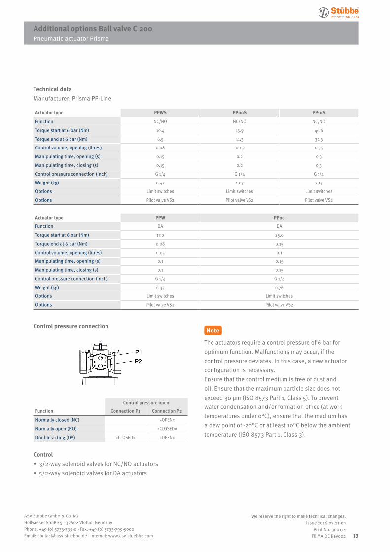
Additional options Ball valve C 200 Pneumatic actuator Prisma
Technical dataManufacturer: Prisma PP-Line
Actuator type PPWS PP00S PP10S
Function NC/NO NC/NO NC/NO
Torque start at 6 bar (Nm) 10.4 15.9 46.6
Torque end at 6 bar (Nm) 6.5 11.3 32.3
Control volume, opening (litres) 0.08 0.15 0.35
Manipulating time, opening (s) 0.15 0.2 0.3
Manipulating time, closing (s) 0.15 0.2 0.3
Control pressure connection (inch) G 1/4 G 1/4 G 1/4
Weight (kg) 0.47 1.03 2.15
Options Limit switches Limit switches Limit switches
Options Pilot valve VS2 Pilot valve VS2 Pilot valve VS2
Actuator type PPW PP00
Function DA DA
Torque start at 6 bar (Nm) 17.0 25.0
Torque end at 6 bar (Nm) 0.08 0.15
Control volume, opening (litres) 0.05 0.1
Manipulating time, opening (s) 0.1 0.15
Manipulating time, closing (s) 0.1 0.15
Control pressure connection (inch) G 1/4 G 1/4
Weight (kg) 0.33 0.76
Options Limit switches Limit switches
Options Pilot valve VS2 Pilot valve VS2
Pneumatic actuator Prisma
Control pressure connection
Control pressure open
Function Connection P1 Connection P2
Normally closed (NC) »OPEN«
Normally open (NO) »CLOSED«
Double-acting (DA) »CLOSED« »OPEN«
Control • 3/2-way solenoid valves for NC/NO actuators • 5/2-way solenoid valves for DA actuators
Note
The actuators require a control pressure of 6 bar for optimum function. Malfunctions may occur, if the control pressure deviates. In this case, a new actuator configuration is necessary.Ensure that the control medium is free of dust and oil. Ensure that the maximum particle size does not exceed 30 µm (ISO 8573 Part 1, Class 5). To prevent water condensation and/or formation of ice (at work temperatures under 0°C), ensure that the medium has a dew point of -20°C or at least 10°C below the ambient temperature (ISO 8573 Part 1, Class 3).
14
ASV Stübbe GmbH & Co. KGHollwieser Straße 5 · 32602 Vlotho, GermanyPhone: +49 (0) 5733-799-0 · Fax: +49 (0) 5733-799-5000Email: [email protected] · Internet: www.asv-stuebbe.com
We reserve the right to make technical changes.Issue 2016.03.21-en
Print No. 300174TR MA DE Rev002
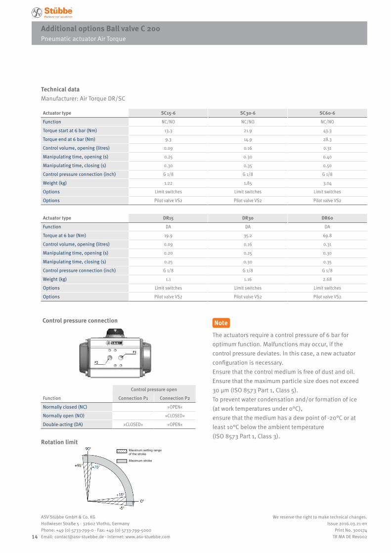
Ball valve C 200Pneumatic actuator Air TorqueAdditional options Ball valve C 200 Pneumatic actuator Air Torque
Technical dataManufacturer: Air Torque DR/SC
Actuator type SC15-6 SC30-6 SC60-6
Function NC/NO NC/NO NC/NO
Torque start at 6 bar (Nm) 13.3 21.9 43.3
Torque end at 6 bar (Nm) 9.3 14.9 28.3
Control volume, opening (litres) 0.09 0.16 0.31
Manipulating time, opening (s) 0.25 0.30 0.40
Manipulating time, closing (s) 0.30 0.35 0.50
Control pressure connection (inch) G 1/8 G 1/8 G 1/8
Weight (kg) 1.22 1.85 3.04
Options Limit switches Limit switches Limit switches
Options Pilot valve VS2 Pilot valve VS2 Pilot valve VS2
Actuator type DR15 DR30 DR60
Function DA DA DA
Torque at 6 bar (Nm) 19.9 35.2 69.8
Control volume, opening (litres) 0.09 0.16 0.31
Manipulating time, opening (s) 0.20 0.25 0.30
Manipulating time, closing (s) 0.25 0.30 0.35
Control pressure connection (inch) G 1/8 G 1/8 G 1/8
Weight (kg) 1.1 1.16 2.68
Options Limit switches Limit switches Limit switches
Options Pilot valve VS2 Pilot valve VS2 Pilot valve VS2
Pneumatic actuator Air Torque
Control pressure open
Function Connection P1 Connection P2
Normally closed (NC) »OPEN«
Normally open (NO) »CLOSED«
Double-acting (DA) »CLOSED« »OPEN«
Control pressure connection
Rotation limit
Note
The actuators require a control pressure of 6 bar for optimum function. Malfunctions may occur, if the control pressure deviates. In this case, a new actuator configuration is necessary.Ensure that the control medium is free of dust and oil. Ensure that the maximum particle size does not exceed 30 µm (ISO 8573 Part 1, Class 5). To prevent water condensation and/or formation of ice (at work temperatures under 0°C), ensure that the medium has a dew point of -20°C or at least 10°C below the ambient temperature (ISO 8573 Part 1, Class 3).
Maximum setting range of the stroke
Maximum stroke
Ball valve C 200
15
ASV Stübbe GmbH & Co. KGHollwieser Straße 5 · 32602 Vlotho, GermanyPhone: +49 (0) 5733-799-0 · Fax: +49 (0) 5733-799-5000Email: [email protected] · Internet: www.asv-stuebbe.com
We reserve the right to make technical changes.Issue 2016.03.21-en
Print No. 300174TR MA DE Rev002
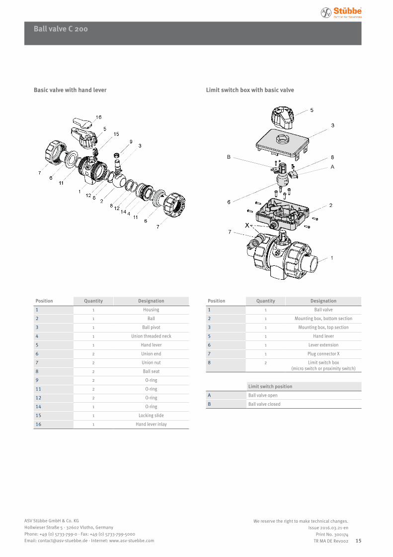
Position Quantity Designation
1 1 Housing
2 1 Ball
3 1 Ball pivot
4 1 Union threaded neck
5 1 Hand lever
6 2 Union end
7 2 Union nut
8 2 Ball seat
9 2 O-ring
11 2 O-ring
12 2 O-ring
14 1 O-ring
15 1 Locking slide
16 1 Hand lever inlay
Basic valve with hand lever Limit switch box with basic valve
Position Quantity Designation
1 1 Ball valve
2 1 Mounting box, bottom section
3 1 Mounting box, top section
5 1 Hand lever
6 1 Lever extension
7 1 Plug connector X
8 2 Limit switch box (micro switch or proximity switch)
A
B
Limit switch position
A Ball valve open
B Ball valve closed
Ball valve C 200
16
ASV Stübbe GmbH & Co. KGHollwieser Straße 5 · 32602 Vlotho, GermanyPhone: +49 (0) 5733-799-0 · Fax: +49 (0) 5733-799-5000Email: [email protected] · Internet: www.asv-stuebbe.com
We reserve the right to make technical changes.Issue 2016.03.21-en
Print No. 300174TR MA DE Rev002
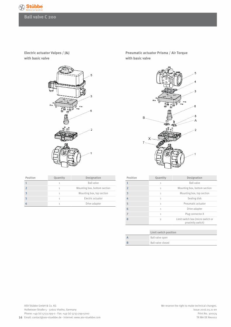
Position Quantity Designation
1 1 Ball valve
2 1 Mounting box, bottom section
3 1 Mounting box, top section
5 1 Electric actuator
6 1 Drive adapter
Position Quantity Designation
1 1 Ball valve
2 1 Mounting box, bottom section
3 1 Mounting box, top section
4 1 Sealing disk
5 1 Pneumatic actuator
6 1 Drive adapter
7 1 Plug connector X
8 2 Limit switch box (micro switch or proximity switch)
X
AB
Electric actuator Valpes / J&J with basic valve
Pneumatic actuator Prisma / Air Torque with basic valve
Limit switch position
A Ball valve open
B Ball valve closed