Embed Size (px)
Citation preview
Arcserve® Unified Data
Protection Appliance User
GuideVersion 6.0
Legal NoticeThis Documentation, which includes embedded help systems and electronically distributed materials, (here-inafter referred to as the “Documentation”) is for your informational purposes only and is subject to change orwithdrawal by Arcserve at any time. This Documentation is proprietary information of Arcserve and may not becopied, transferred, reproduced, disclosed, modified or duplicated, in whole or in part, without the prior writ-ten consent of Arcserve.
If you are a licensed user of the software product(s) addressed in the Documentation, you may print or oth-erwise make available a reasonable number of copies of the Documentation for internal use by you and youremployees in connection with that software, provided that all Arcserve copyright notices and legends areaffixed to each reproduced copy.
The right to print or otherwise make available copies of the Documentation is limited to the period duringwhich the applicable license for such software remains in full force and effect. Should the license terminatefor any reason, it is your responsibility to certify in writing to Arcserve that all copies and partial copies of theDocumentation have been returned to Arcserve or destroyed.
TO THE EXTENT PERMITTED BY APPLICABLE LAW, ARCSERVE PROVIDES THIS DOCUMENTATION “AS IS”WITHOUT WARRANTY OF ANY KIND, INCLUDING WITHOUT LIMITATION, ANY IMPLIED WARRANTIES OFMERCHANTABILITY, FITNESS FOR A PARTICULAR PURPOSE, OR NONINFRINGEMENT. IN NO EVENT WILLARCSERVE BE LIABLE TO YOU OR ANY THIRD PARTY FOR ANY LOSS OR DAMAGE, DIRECT OR INDIRECT, FROMTHE USE OF THIS DOCUMENTATION, INCLUDING WITHOUT LIMITATION, LOST PROFITS, LOST INVESTMENT,BUSINESS INTERRUPTION, GOODWILL, OR LOST DATA, EVEN IF ARCSERVE IS EXPRESSLY ADVISED INADVANCE OF THE POSSIBILITY OF SUCH LOSS OR DAMAGE.
The use of any software product referenced in the Documentation is governed by the applicable license agree-ment and such license agreement is not modified in any way by the terms of this notice.
The manufacturer of this Documentation is Arcserve.
Provided with “Restricted Rights.” Use, duplication or disclosure by the United States Government is subject tothe restrictions set forth in FAR Sections 12.212, 52.227-14, and 52.227-19(c)(1) - (2) and DFARS Section252.227-7014(b)(3), as applicable, or their successors.
© 2017 Arcserve, including its affiliates and subsidiaries. All rights reserved. Any third party trademarks orcopyrights are the property of their respective owners.
Contact Arcserve SupportThe Arcserve Support team offers a rich set of resources for resolving your tech-nical issues and provides easy access to important product information.
Contact Support
With Arcserve Support:
You can get in direct touch with the same library of information that is sharedinternally by our Arcserve Support experts. This site provides you with access toour knowledge-base (KB) documents. From here you easily search for and findthe product-related KB articles which contain field-tested solutions for manytop issues and common problems.
You can use our Live Chat link to instantly launch a real-time conversationbetween you and the Arcserve Support team. With Live Chat, you can get imme-diate answers to your concerns and questions, while still maintaining access tothe product.
You can participate in the Arcserve Global User Community to ask and answerquestions, share tips and tricks, discuss best practices and participate in con-versations with your peers.
You can open a support ticket. By opening a support ticket online, you canexpect a callback from one of our experts in the product area you are inquiringabout.
You can access other helpful resources appropriate for your Arcserve product.
Arcserve UDP Appliance Return PolicyA valid RMA (Return Material Authorization) number is required to return aproduct to Arcserve. Contact the Arcserve Technical Support department to obtainan RMA number. Refer to arcserve.com/support to contact customer care. Supportteam can inform where to send the RMA data.
Returns are subject to a re-stocking fee of 10%. Exceptions are: 1) If an order wasfulfilled incorrectly, Arcserve will accept RMA and provide full credit; 2) If a defect-ive item is returned within 30 days, Arcserve will accept RMA and provide fullcredit; and 3) If there are hardware technical issues that are unresolved by supportafter a reasonable period of time to resolve, Arcserve will accept RMA and providea hardware swap for a unit of equivalent value.
Information needed for the RMA request:
Product serial number (located on the back of the appliance)
Arcserve Order Number
Partner contact name
Partner phone number
Partner Email address
Customer contact name (if available)
Phone number (if available)
Email address (if available)
Description of problem and any troubleshooting already performed.
Shipping service requested and shipping address.
The RMA number must be clearly marked on the outside of the packaging. AllRMAs must be shipped using adequate packaging. All RMAs should be shippedusing a reputable carrier that offers package tracking and insurance. Any shippingdamage or lost RMAs is the responsibility of customer.
Contents
Chapter 1: About Appliance Documentation 9Language Support 10
Product Documentation 11
Chapter 2: Introducing the Arcserve UDP Appliance 12Introduction 13
Arcserve Unified Data Protection 14
Arcserve UDP Agent (Linux) 15
Arcserve Replication and High Availability (Arcserve RHA) 16
Arcserve Backup 17
Safety Precautions 18
What is Included in the Box 19
What is Not Included in the Box 20
AvailableModels 21
Models 7100-7300v 22
Models 7400-7600v 24
Models 8100-8400 26
Controls and Indicators 28
Front Panel 7100-7300v 29
Front Panel 7400-7600v 31
Front Panel 8100-8200 33
Front Panel 8300-8400 35
Rear Panel 7100-7300v 37
Rear Panel 7400-7600v 39
Rear Panel 8100-8200 41
Rear Panel 8300-8400 43
Ports Used by the Appliance 45
Arcserve UDP 46
Components installed on Microsoft Windows 47
Components installed on Linux 49
Production node protected by UDP Linux remotely 50
Arcserve Backup 51
Appliance for Linux Support 52
Chapter 3: Installing the Arcserve UDP Appliance 53
5 Arcserve UDP Appliance User Guide
How to Install Arcserve Backup r17.5 54
How to Install 8100-8200 Series Appliance 56
How to Install 8300-8400 Series Appliance 57
Chapter 4: Understanding Network Configuration 58How to Configure the NIC Teaming Process 59
How to Disable DHCP Server 61
How to Understand the Network Configuration on the UDP Appliance 62
How to Configure IP Address for the preinstalled Linux Backup Server 66
How to Enable Round Robin on the DNS Server to Balance Load 68
Chapter 5: Upgrading Arcserve UDP on the Appliance 69How to Apply a License After Upgrading Arcserve Software 70
Upgrade Sequence on the Arcserve UDP Appliance 71
Upgrade the Arcserve UDP Appliance that performs as Arcserve UDP Console and RPS 72
Upgrade the Arcserve UDP Appliance that performs as Arcserve UDP RPS only 73
Upgrade Steps When Two or More Arcserve UDP Appliances Are Used in the Envir-onment 74
Upgrade the Arcserve UDP Linux Agent on the Arcserve UDP Appliance 75
Upgrade the Arcserve Backup on the Arcserve UDP Appliance 76
Upgrade Sequence for UDP Console, RPS, and Agent 77
Chapter 6: Configuring the Arcserve UDP Appliance 78How to Configure Network Settings for a UDP Appliance 79
Overview of Creating a Plan Using the UDP ApplianceWizard 83
How to Set up the Arcserve UDP Appliance and Create Plans 84
Additional Information on Adding Nodes to a Plan 93
Add Nodes by Hostname/IP Address 94
Add Nodes by Active Directory 96
Add vCenter/ESX Nodes 98
Add Hyper-V Nodes 100
Configure UDP Appliance as Gateway 102
Clear Configuration and Apply Appliance Factory Reset 103
Apply Arcserve UDP Factory Reset Using Boot Option 105
How to Activate Arcserve Product on the Appliance 108
Chapter 7: Creating Backup Plans 109Create a Backup Plan for Linux Nodes 110
Create a Backup Plan to a Tape Device 111
Create an On-Appliance Virtual Standby Plan 112
6
Chapter 8: Repairing the Arcserve UDP Appliance 113Remove and Replace a Hard Drive 114
Chapter 9: Safety Precautions 118General Safety Precautions 119
Electrical Safety Precautions 121
FCC Compliance 122
Electrostatic Discharge (ESD) Precautions 123
Chapter 10: Changing the IPMI Password 124How to Change the IPMI Password 125
Chapter 11: Connecting Appliance Expansion Shelf to the Appli-ance Server 129Appliance Infield Expansion for all the AvailableModels 130
What is included in the box 140
How to Connect the Appliance Expansion Shelf to the Appliance Server 143
How to Modify Arcserve UDP Data store 152
Adding a data path on the expansion shelf to the Arcserve UDP data store 153
Migrating Hash Destination to the new SSD 154
Checking the overall capacity of the <hostname_data_store> data store from the Arc-serve UDP Console 155
Resuming all the plans from Arcserve UDP Console 156
Chapter 12: Troubleshooting 157Linux Backup Server Fails to Connect from the Console 158
Backing Up a UDP Appliance from Another Appliance Reports Duplicated Nodes 160
Linux Backup Server Cannot Get the Network DNS Suffix 162
Default Time Zone on the Appliance 163
Licenses Error even when the licenses are available 164
Chapter 13: Best Practices 165Best Practices for Network Configuration 166
Best Practices for Arcserve UDP ConsoleMigration 169
Best Practices for Set Appliance Image Utility Tool 171
Best Practices for pre-installed Linux Backup Server in the Arcserve UDP Appliance 174
Best Practices for Arcserve UDP Appliance to backup the Linux Backup Server itself 176
Best Practices to Migrate from Arcserve UDP Appliance to Appliance 180
Solution 1 181
Solution 2 185
Best Practices for Arcserve UDP Linux instant VM job to Local Appliance Hyper-V 187
7 Arcserve UDP Appliance User Guide
Best Practices to add Replicate to a remotely managed RPS task to another Appli-ance 188
Best Practices to perform Virtual Standby (VSB) task for which themonitor isanother Appliance 190
Chapter 14: Acknowledgements 192putty 193
8
Chapter 1: About Appliance DocumentationArcserve UDP Appliance User Guide helps you understand how to use Arcserve UDPAppliance. To understand about UDP Appliance, view Introduction. Rest of the sec-tions help you install and use Arcserve UDP Appliance.
This section contains the following topics:
Language Support 10
Product Documentation 11
Chapter 1: About Appliance Documentation 9
Language Support
Language Support
Documentation is available in English as well as multiple local languages.
A translated product (sometimes referred to as a localized product) includes locallanguage support for the user interface of the product, online help and other doc-umentation, as well as local language default settings for date, time, currency, andnumber formats.
This release is available in the following languages:
English
Chinese (Simplified)
Chinese (Traditional)
French
German
Italian
Japanese
Portuguese (Brazil)
Spanish
10 Arcserve UDP Appliance User Guide
Product Documentation
Product Documentation
For all Arcserve UDP related documentation, click this link for the Arcserve Docu-mentation.
The Arcserve UDP Knowledge Center consists of the following documentation:
Arcserve UDP Solutions Guide
Provides detailed information on how to use the Arcserve UDP solution in acentrally-managed Console environment. This guide includes such informationas how to install and configure the solution, how to protect and restore yourdata, how to get reports, and how to manage Arcserve High Availability. Pro-cedures are centered around use of the Console and includes how to use thevarious protection Plans.
Arcserve UDP Release Notes
Provides high-level description of the major features, system requirements,known issues, documentation issues, and limitations of Arcserve Unified DataProtection.
Arcserve UDP Agent for Windows User Guide
Provides detailed information on how to use Arcserve UDP Agent in a Windowsoperating system. This guide includes such information as how to install andconfigure the agent and how to protect and restore your Windows nodes.
Arcserve UDP Agent for Linux User Guide
Provides detailed information on how to use Arcserve UDP Agent in a Linuxoperating system. This guide includes such information as how to install andconfigure the agent and how to protect and restore your Linux nodes.
Chapter 1: About Appliance Documentation 11
Chapter 2: Introducing the Arcserve UDP ApplianceThis section contains the following topics:
Introduction 13
Safety Precautions 18
What is Included in the Box 19
What is Not Included in the Box 20
AvailableModels 21
Controls and Indicators 28
Ports Used by the Appliance 45
Chapter 2: Introducing the Arcserve UDP Appliance 12
Introduction
Introduction
The Arcserve UDP appliance is the first complete and most cost-effective data pro-tection appliance, featuring Assured Recovery™. Each Arcserve UDP appliance is aself-contained, "set and forget" backup and recovery solution. Architected withcloud-native capabilities, its unmatched ease of deployment and usability combinewith a broad set of features such as global source-based deduplication, multi-sitereplication, tape support, and automated data recovery capabilities. The ArcserveUDP appliance delivers unmatched operational agility and efficiency, and truly sim-plifies disaster recovery activities.
The Arcserve UDP appliance is fully integrated with the industry-leading ArcserveUnified Data Protection software pre-installed in state-of-the art hardware. Theappliance provides a complete and integrated data protection solution for all usersto not only meet your current demands, but also the ever-changing backup,archive, and disaster recovery (DR) requirements of the future.
The following software are preinstalled in the Arcserve UDP appliance:
Arcserve UDP
Arcserve UDP Agent (Linux)
Arcserve Backup
Arcserve Replication and High Availability (RHA)
Each Arcserve UDP appliance comes with a 3-year hardware warranty. Please visitarcserve.com/udp-appliance-warranty for detailed information about this war-ranty.
13 Arcserve UDP Appliance User Guide
Introduction
Arcserve Unified Data Protection
The Arcserve UDP software is a comprehensive solution to protect complex IT envir-onments. The solution protects your data residing in various types of nodes such asWindows, Linux, and virtual machines on VMware ESX Servers or Microsoft Hyper-V Servers. You can back up data to either a local machine or a recovery pointServer. A recovery point Server is a central Server where backups from multiplesources are stored.
Arcserve UDP provides the following capabilities:
Back up the data to deduplication/non-deduplication data stores on recoverypoint Servers
Back up recovery points to tape, using integration with Arcserve Backup (whichis also included within the appliance)
Create virtual standby machines from backup data
Replicate backup data to recovery point Servers and remote recovery pointServers
Restore backup data and performs Bare Metal Recovery (BMR)
Copy selected data backup files to a secondary backup location
Configure and manage Arcserve Full System High Availability (HA) for criticalServers in your environment
Arcserve UDP replicates backup data that is saved as recovery points from oneServer to another recovery point Server. You can also create virtual machines fromthe backup data that can act as standby machines when the source node fails. Thestandby virtual machine is created by converting recovery points to VMware ESX orMicrosoft Hyper-V virtual machine format.
The Arcserve UDP solution provides integration with Arcserve High Availability.After you create scenarios in Arcserve High Availability, you can then manage andmonitor your scenarios and perform operations like adding or deleting destinationmachines.
Chapter 2: Introducing the Arcserve UDP Appliance 14
Introduction
Arcserve UDP Agent (Linux)
Arcserve UDP Agent (Linux) is a disk-based backup product that is designed forLinux operating systems. It provides a fast, simple, and reliable way to protect andrecover critical business information. Arcserve UDP Agent (Linux) tracks changes ona node at the block level and then backs up only those changed blocks in an incre-mental process. As a result, it lets you perform frequent backups, reducing the sizeof each incremental backup (and the backup window) and providing a more up-to-date backup. Arcserve UDP Agent (Linux) also provides the capability to restorefiles or folders and perform a bare metal recovery (BMR) from a single backup.You can store the backup information either on a Network File System (NFS) shareor in the Common Internet File System (CIFS) share, in the backup source node.
The latest version of Arcserve UDP Agent (Linux) is preinstalled in a virtual machinewithin the appliance. This virtual machine becomes the Linux Backup Server. Arc-serve UDP Agent (Linux) is installed at the default installation path in the UDP Appli-ance.
When you open the Console, the Linux Backup Server is already added to the Con-sole. The native host name of the Linux Backup Server is Linux-BackupSvr. However,on the Console, the Linux Backup Server adopts the host name of the Appliancewith port 8018 configuration. The Linux Backup Server works behind NAT throughport direction. The Linux Backup Server uses port 8018 to communicate and trans-fer data in the Arcserve UDP Appliance.
Note: For more information about creating backup plans and restoring Linuxmachines, see Arcserve UDP Agent for Linux User Guide.
The Linux Backup Server uses the following default login information:
Username – root
Password - Arcserve
Note:We recommend to change the default password.
15 Arcserve UDP Appliance User Guide
Introduction
Arcserve Replication and High Availability (ArcserveRHA)
Arcserve RHA is a solution based on asynchronous real-time replication and auto-mated application switchover and switchback to provide cost-effective business con-tinuity for virtual environments on Windows Servers.
Arcserve RHA lets you replicate data to a local or remote Server, helping you torecover that data if you face a Server crash or site disaster. You may switch yourusers to the replica Server manually, or automatically, if you have licensed HighAvailability.
You can download the full installation package of Arcserve RHA from Arcserve web-site to install all components. For details, refer to Arcserve RHA online documents.
Chapter 2: Introducing the Arcserve UDP Appliance 16
Introduction
Arcserve Backup
Arcserve Backup is a high-performance data protection solution that addresses theneeds of businesses with heterogeneous environments. It provides flexible backupand restore performance, easy administration, broad device compatibility, and reli-ability. It helps you to maximize your data storage abilities that lets you customizeyour data protection strategies based on your storage requirements. In addition,the flexible user interface allows advanced configurations and provides a cost-effective way for users at all levels of technical expertise to deploy and maintain anextensive range of agents and options.
Arcserve Backup delivers comprehensive data protection for distributed envir-onments and provides virus-free backup and restore operations. An extensive set ofoptions and agents extends data protection throughout the enterprise and deliversenhanced functionality, including online hot backup and restore of application anddata files, advanced device and media management, and disaster recovery.
UDP Appliance includes integration with Arcserve Backup for performing a backupto tape. Arcserve Backup is installed at "C:\Program Files (x86)\Arcserve" on yourcomputer after you run InstallASBU.bat. The components installed in the UDP Appli-ance lets you back up the destination of Arcserve UDP to a tape.
You can download the full installation package of Arcserve Backup from Arcservewebsite to install other components. For details, refer to Arcserve Backup onliner17.5 online documents.
Arcserve Backup Server uses the following default login information:
Username -- caroot
Password -- Arcserve
17 Arcserve UDP Appliance User Guide
Safety Precautions
Safety Precautions
For your safety, please read and follow all instructions before attempting tounpack, connect, install, power on, or operate an Arcserve UDP appliance. Failureto adhere to the safety precautions can result in personal injury, equipment dam-age, or malfunction.
For more information about the safety precautions, see the Safety PrecautionsAppendix.
Chapter 2: Introducing the Arcserve UDP Appliance 18
What is Included in the Box
What is Included in the Box
The following items are contained in the box:
Arcserve UDP Appliance (serial number label is located on rear of appliance)
Power cable: 1
Network Cables: 1 red, 1 blue (3-feet long each)
IPMI port cable: 1 (7-feet long)
Rail/Rack Mounting Kit - consisting of 2 quick-install outer rails, 2 inner railextensions, 3 rail adapters (standard rail mounting only), and attaching hard-ware (as needed)
Arcserve faceplate
Microsoft Client Access License
Note: Inspect the box that the appliance was shipped in and ensure that no itemsare missing from the box and that there are no visible signs of damage. If any itemsare missing or damaged, please retain all packaging materials and contact Arc-serve Support immediately at: https://www.arcserve.com/support.
19 Arcserve UDP Appliance User Guide
What is Not Included in the Box
What is Not Included in the Box
The following items are not included in the box and may be needed for installationand configuration of the appliance:
Monitor
Keyboard
External Storage Device (if needed)
Chapter 2: Introducing the Arcserve UDP Appliance 20
Available Models
Available Models
The Arcserve UDP 7000 series and 8000 series appliances are available in a varietyof different models designed to meet your specific needs:
Models 7100 - 7300v
Models 7400 - 7600v
Models 8100 - 8400
21 Arcserve UDP Appliance User Guide
Available Models
Models 7100-7300v
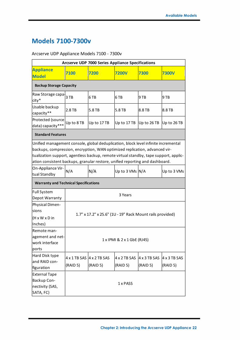
Arcserve UDP Appliance Models 7100 - 7300v
Arcserve UDP 7000 Series Appliance Specifications
ApplianceModel
7100 7200 7200V 7300 7300V
Backup Storage Capacity
Raw Storage capa-city*
3 TB 6 TB 6 TB 9 TB 9 TB
Usable backupcapacity**
2.8 TB 5.8 TB 5.8 TB 8.8 TB 8.8 TB
Protected (sourcedata) capacity***
Up to 8 TB Up to 17 TB Up to 17 TB Up to 26 TB Up to 26 TB
Standard Features
Unified management console, global deduplication, block level infinite incrementalbackups, compression, encryption, WAN optimized replication, advanced vir-tualization support, agentless backup, remote virtual standby, tape support, applic-ation consistent backups, granular restore, unified reporting and dashboard.On-Appliance Vir-tual Standby
N/A N/A Up to 3 VMs N/A Up to 3 VMs
Warranty and Technical Specifications
Full SystemDepot Warranty
3 Years
Physical Dimen-sions
(H xW x D inInches)
1.7" x 17.2" x 25.6" (1U - 19" Rack Mount rails provided)
Remote man-agement and net-work interfaceports
1 x IPMI & 2 x 1 GbE (RJ45)
Hard Disk typeand RAID con-figuration
4 x 1 TB SAS
(RAID 5)
4 x 2 TB SAS
(RAID 5)
4 x 2 TB SAS
(RAID 5)
4 x 3 TB SAS
(RAID 5)
4 x 3 TB SAS
(RAID 5)
External TapeBackup Con-nectivity (SAS,SATA, FC)
1 x PASS
Chapter 2: Introducing the Arcserve UDP Appliance 22
Available Models
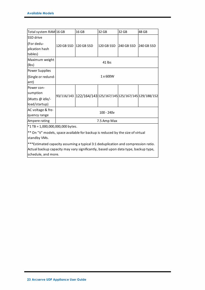
Total system RAM 16 GB 16 GB 32 GB 32 GB 48 GBSSD drive
(For dedu-plication hashtables)
120 GB SSD 120 GB SSD 120 GB SSD 240 GB SSD 240 GB SSD
Maximum weight(lbs)
41 lbs
Power Supplies
(Single or redund-ant)
1 x 600W
Power con-sumption
(Watts @ idle/-load/startup)
93/116/143 122/164/143 125/167/145 125/167/145 129/188/152
AC voltage & fre-quency range
100 - 240v
Ampere rating 7.5 Amp Max*1 TB = 1,000,000,000,000 bytes.
** On "V" models, space available for backup is reduced by the size of virtualstandby VMs.
***Estimated capacity assuming a typical 3:1 deduplication and compression ratio.Actual backup capacity may vary significantly, based upon data type, backup type,schedule, and more.
23 Arcserve UDP Appliance User Guide
Available Models
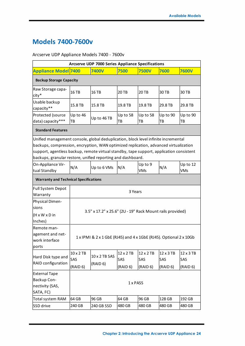
Models 7400-7600v
Arcserve UDP Appliance Models 7400 - 7600v
Arcserve UDP 7000 Series Appliance Specifications
Appliance Model 7400 7400V 7500 7500V 7600 7600V
Backup Storage Capacity
Raw Storage capa-city*
16 TB 16 TB 20 TB 20 TB 30 TB 30 TB
Usable backupcapacity**
15.8 TB 15.8 TB 19.8 TB 19.8 TB 29.8 TB 29.8 TB
Protected (sourcedata) capacity***
Up to 46TB
Up to 46 TBUp to 58TB
Up to 58TB
Up to 90TB
Up to 90TB
Standard Features
Unified management console, global deduplication, block level infinite incrementalbackups, compression, encryption, WAN optimized replication, advanced virtualizationsupport, agentless backup, remote virtual standby, tape support, application consistentbackups, granular restore, unified reporting and dashboard.On-Appliance Vir-tual Standby
N/A Up to 6 VMs N/AUp to 9VMs
N/AUp to 12VMs
Warranty and Technical Specifications
Full System DepotWarranty
3 Years
Physical Dimen-sions
(H xW x D inInches)
3.5" x 17.2" x 25.6" (2U - 19" Rack Mount rails provided)
Remote man-agement and net-work interfaceports
1 x IPMI & 2 x 1 GbE (RJ45) and 4 x 1GbE (RJ45). Optional 2 x 10Gb
Hard Disk type andRAID configuration
10 x 2 TBSAS
(RAID 6)
10 x 2 TB SAS
(RAID 6)
12 x 2 TBSAS
(RAID 6)
12 x 2 TBSAS
(RAID 6)
12 x 3 TBSAS
(RAID 6)
12 x 3 TBSAS
(RAID 6)External TapeBackup Con-nectivity (SAS,SATA, FC)
1 x PASS
Total system RAM 64 GB 96 GB 64 GB 96 GB 128 GB 192 GBSSD drive 240 GB 240 GB SSD 480 GB 480 GB 480 GB 480 GB
Chapter 2: Introducing the Arcserve UDP Appliance 24
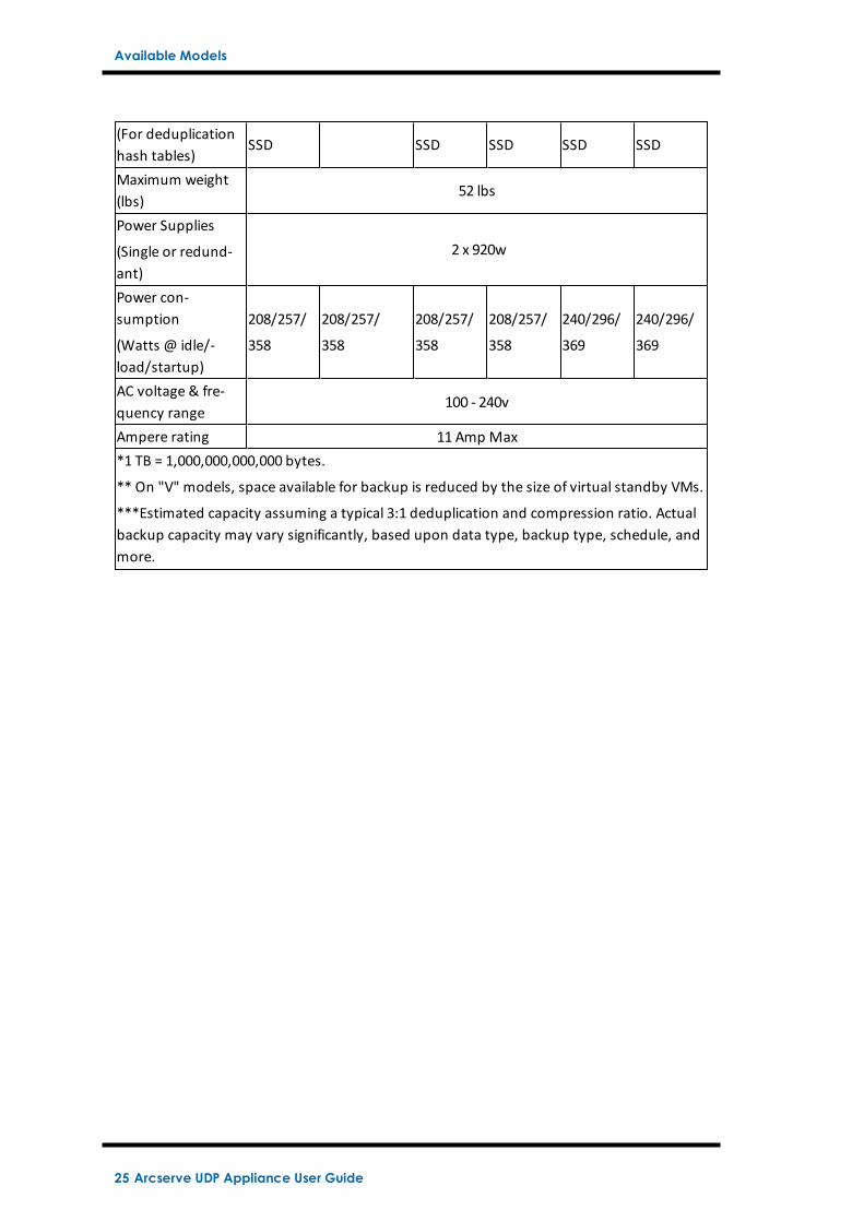
Available Models
(For deduplicationhash tables)
SSD SSD SSD SSD SSD
Maximum weight(lbs)
52 lbs
Power Supplies
(Single or redund-ant)
2 x 920w
Power con-sumption
(Watts @ idle/-load/startup)
208/257/
358
208/257/
358
208/257/
358
208/257/
358
240/296/
369
240/296/
369
AC voltage & fre-quency range
100 - 240v
Ampere rating 11 Amp Max*1 TB = 1,000,000,000,000 bytes.
** On "V" models, space available for backup is reduced by the size of virtual standby VMs.
***Estimated capacity assuming a typical 3:1 deduplication and compression ratio. Actualbackup capacity may vary significantly, based upon data type, backup type, schedule, andmore.
25 Arcserve UDP Appliance User Guide
Available Models
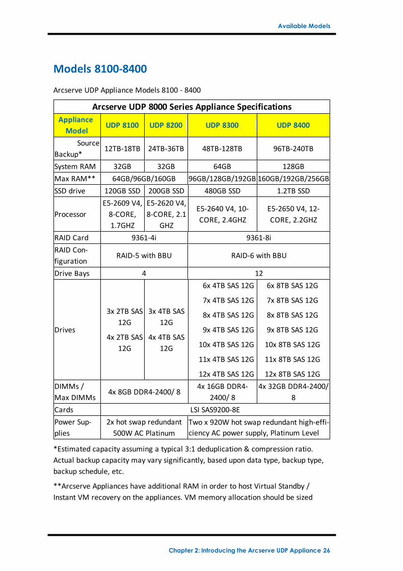
Models 8100-8400
Arcserve UDP Appliance Models 8100 - 8400
Arcserve UDP 8000 Series Appliance SpecificationsApplianceModel
UDP 8100 UDP 8200 UDP 8300 UDP 8400
SourceBackup*
12TB-18TB 24TB-36TB 48TB-128TB 96TB-240TB
System RAM 32GB 32GB 64GB 128GBMax RAM** 64GB/96GB/160GB 96GB/128GB/192GB 160GB/192GB/256GBSSD drive 120GB SSD 200GB SSD 480GB SSD 1.2TB SSD
ProcessorE5-2609 V4,8-CORE,1.7GHZ
E5-2620 V4,8-CORE, 2.1
GHZ
E5-2640 V4, 10-CORE, 2.4GHZ
E5-2650 V4, 12-CORE, 2.2GHZ
RAID Card 9361-4i 9361-8iRAID Con-figuration
RAID-5 with BBU RAID-6 with BBU
Drive Bays 4 12
Drives
3x 2TB SAS12G
4x 2TB SAS12G
3x 4TB SAS12G
4x 4TB SAS12G
6x 4TB SAS 12G
7x 4TB SAS 12G
8x 4TB SAS 12G
9x 4TB SAS 12G
10x 4TB SAS 12G
11x 4TB SAS 12G
12x 4TB SAS 12G
6x 8TB SAS 12G
7x 8TB SAS 12G
8x 8TB SAS 12G
9x 8TB SAS 12G
10x 8TB SAS 12G
11x 8TB SAS 12G
12x 8TB SAS 12GDIMMs /Max DIMMs
4x 8GB DDR4-2400/ 84x 16GB DDR4-
2400/ 84x 32GB DDR4-2400/
8Cards LSI SAS9200-8EPower Sup-plies
2x hot swap redundant500W AC Platinum
Two x 920W hot swap redundant high-effi-ciency AC power supply, Platinum Level
*Estimated capacity assuming a typical 3:1 deduplication & compression ratio.Actual backup capacity may vary significantly, based upon data type, backup type,backup schedule, etc.
**Arcserve Appliances have additional RAM in order to host Virtual Standby /Instant VM recovery on the appliances. VM memory allocation should be sized
Chapter 2: Introducing the Arcserve UDP Appliance 26
Available Models
based on guest OS workload. Arcserve also provides the option to add additionalRAM to the standard appliance configuration based on customer needs.
27 Arcserve UDP Appliance User Guide
Controls and Indicators
Controls and Indicators
The Arcserve UDP Appliance contains several controls and indicators (LEDs) on thefront and rear panels and on each drive carrier. These controls and indicatorsprovide the capability to control various functions and a quick-view reference of thestatus of the appliance and components:
Front Panel 7100-7300v
Front Panel 7400-7600v
Front Panel 8100-8200
Front Panel 8300-8400
Rear Panel 7100-7300v
Rear Panel 7400-7600v
Rear Panel 8100-8200
Rear Panel 8300-8400
Chapter 2: Introducing the Arcserve UDP Appliance 28
Controls and Indicators
Front Panel 7100-7300v
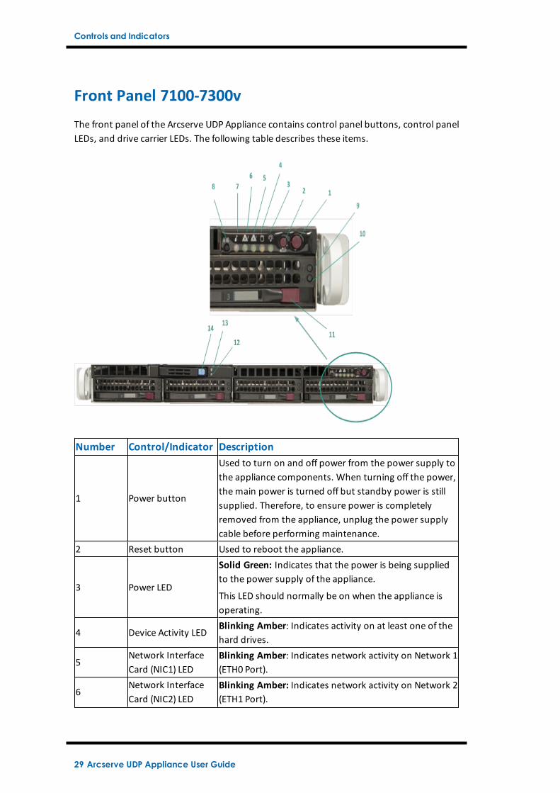
The front panel of the Arcserve UDP Appliance contains control panel buttons, control panelLEDs, and drive carrier LEDs. The following table describes these items.
Number Control/Indicator Description
1 Power button
Used to turn on and off power from the power supply tothe appliance components. When turning off the power,the main power is turned off but standby power is stillsupplied. Therefore, to ensure power is completelyremoved from the appliance, unplug the power supplycable before performing maintenance.
2 Reset button Used to reboot the appliance.
3 Power LED
Solid Green: Indicates that the power is being suppliedto the power supply of the appliance.
This LED should normally be on when the appliance isoperating.
4 Device Activity LEDBlinking Amber: Indicates activity on at least one of thehard drives.
5Network InterfaceCard (NIC1) LED
Blinking Amber: Indicates network activity on Network 1(ETH0 Port).
6Network InterfaceCard (NIC2) LED
Blinking Amber: Indicates network activity on Network 2(ETH1 Port).
29 Arcserve UDP Appliance User Guide
Controls and Indicators
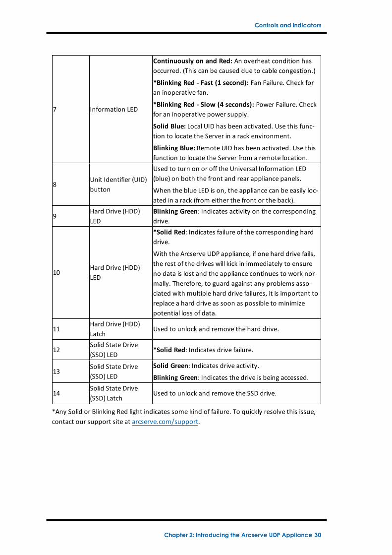
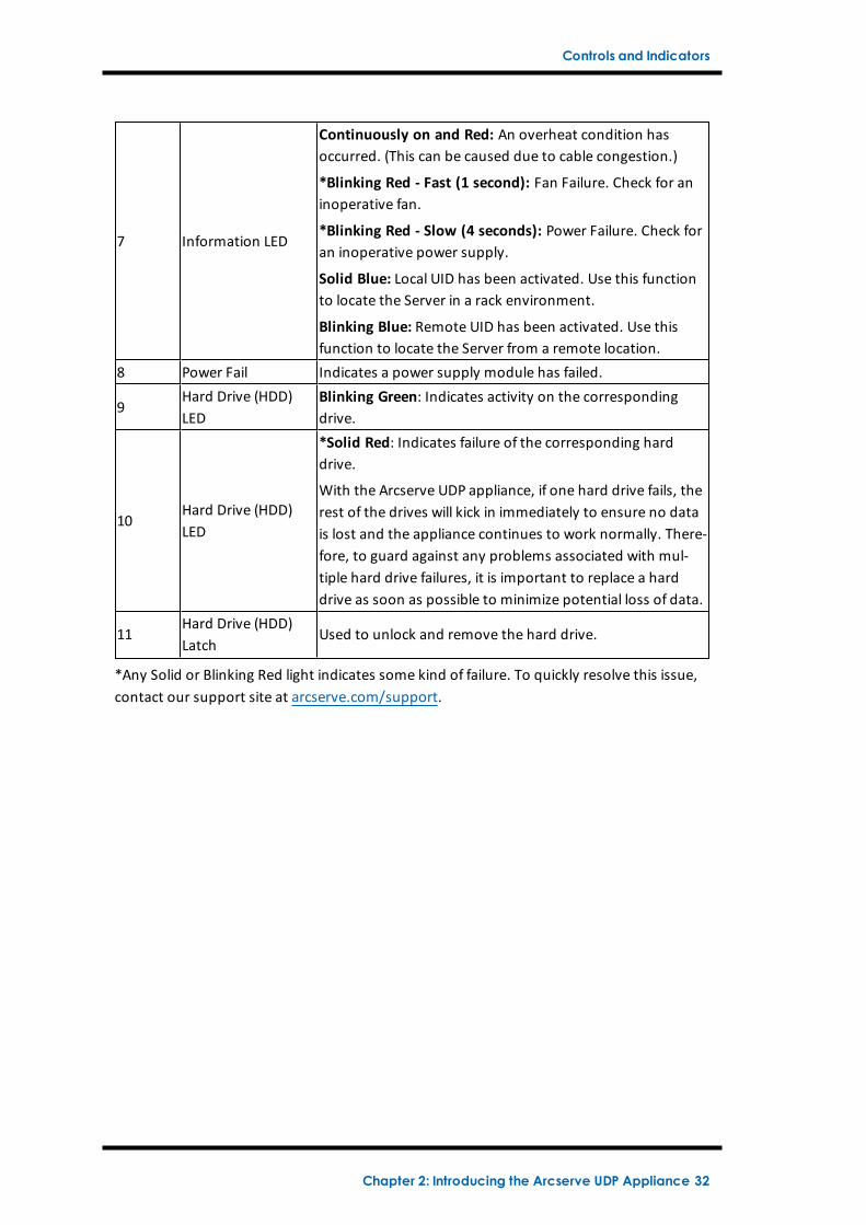
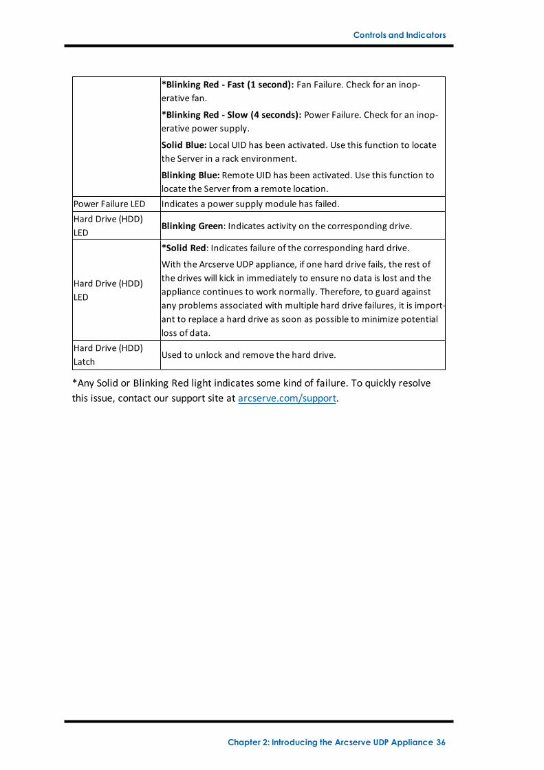
7 Information LED
Continuously on and Red: An overheat condition hasoccurred. (This can be caused due to cable congestion.)
*Blinking Red - Fast (1 second): Fan Failure. Check foran inoperative fan.
*Blinking Red - Slow (4 seconds): Power Failure. Checkfor an inoperative power supply.
Solid Blue: Local UID has been activated. Use this func-tion to locate the Server in a rack environment.
Blinking Blue: Remote UID has been activated. Use thisfunction to locate the Server from a remote location.
8Unit Identifier (UID)button
Used to turn on or off the Universal Information LED(blue) on both the front and rear appliance panels.
When the blue LED is on, the appliance can be easily loc-ated in a rack (from either the front or the back).
9Hard Drive (HDD)LED
Blinking Green: Indicates activity on the correspondingdrive.
10Hard Drive (HDD)LED
*Solid Red: Indicates failure of the corresponding harddrive.
With the Arcserve UDP appliance, if one hard drive fails,the rest of the drives will kick in immediately to ensureno data is lost and the appliance continues to work nor-mally. Therefore, to guard against any problems asso-ciated with multiple hard drive failures, it is important toreplace a hard drive as soon as possible to minimizepotential loss of data.
11Hard Drive (HDD)Latch
Used to unlock and remove the hard drive.
12Solid State Drive(SSD) LED
*Solid Red: Indicates drive failure.
13Solid State Drive(SSD) LED
Solid Green: Indicates drive activity.
Blinking Green: Indicates the drive is being accessed.
14Solid State Drive(SSD) Latch
Used to unlock and remove the SSD drive.
*Any Solid or Blinking Red light indicates some kind of failure. To quickly resolve this issue,contact our support site at arcserve.com/support.
Chapter 2: Introducing the Arcserve UDP Appliance 30
Controls and Indicators
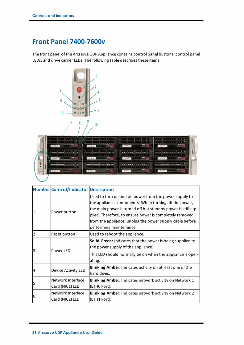
Front Panel 7400-7600v
The front panel of the Arcserve UDP Appliance contains control panel buttons, control panelLEDs, and drive carrier LEDs. The following table describes these items.
Number Control/Indicator Description
1 Power button
Used to turn on and off power from the power supply tothe appliance components. When turning off the power,the main power is turned off but standby power is still sup-plied. Therefore, to ensure power is completely removedfrom the appliance, unplug the power supply cable beforeperforming maintenance.
2 Reset button Used to reboot the appliance.
3 Power LED
Solid Green: Indicates that the power is being supplied tothe power supply of the appliance.
This LED should normally be on when the appliance is oper-ating.
4 Device Activity LEDBlinking Amber: Indicates activity on at least one of thehard dives.
5Network InterfaceCard (NIC1) LED
Blinking Amber: Indicates network activity on Network 1(ETH0 Port).
6Network InterfaceCard (NIC2) LED
Blinking Amber: Indicates network activity on Network 2(ETH1 Port).
31 Arcserve UDP Appliance User Guide
Controls and Indicators
7 Information LED
Continuously on and Red: An overheat condition hasoccurred. (This can be caused due to cable congestion.)
*Blinking Red - Fast (1 second): Fan Failure. Check for aninoperative fan.
*Blinking Red - Slow (4 seconds): Power Failure. Check foran inoperative power supply.
Solid Blue: Local UID has been activated. Use this functionto locate the Server in a rack environment.
Blinking Blue: Remote UID has been activated. Use thisfunction to locate the Server from a remote location.
8 Power Fail Indicates a power supply module has failed.
9Hard Drive (HDD)LED
Blinking Green: Indicates activity on the correspondingdrive.
10Hard Drive (HDD)LED
*Solid Red: Indicates failure of the corresponding harddrive.
With the Arcserve UDP appliance, if one hard drive fails, therest of the drives will kick in immediately to ensure no datais lost and the appliance continues to work normally. There-fore, to guard against any problems associated with mul-tiple hard drive failures, it is important to replace a harddrive as soon as possible to minimize potential loss of data.
11Hard Drive (HDD)Latch
Used to unlock and remove the hard drive.
*Any Solid or Blinking Red light indicates some kind of failure. To quickly resolve this issue,contact our support site at arcserve.com/support.
Chapter 2: Introducing the Arcserve UDP Appliance 32
Controls and Indicators
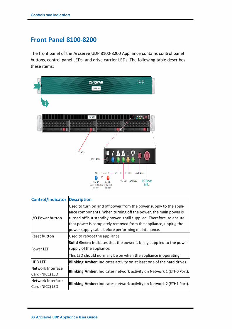
Front Panel 8100-8200
The front panel of the Arcserve UDP 8100-8200 Appliance contains control panelbuttons, control panel LEDs, and drive carrier LEDs. The following table describesthese items:
Control/Indicator Description
I/O Power button
Used to turn on and off power from the power supply to the appli-ance components. When turning off the power, the main power isturned off but standby power is still supplied. Therefore, to ensurethat power is completely removed from the appliance, unplug thepower supply cable before performing maintenance.
Reset button Used to reboot the appliance.
Power LEDSolid Green: Indicates that the power is being supplied to the powersupply of the appliance.
This LED should normally be on when the appliance is operating.HDD LED Blinking Amber: Indicates activity on at least one of the hard drives.Network InterfaceCard (NIC1) LED
Blinking Amber: Indicates network activity on Network 1 (ETH0 Port).
Network InterfaceCard (NIC2) LED
Blinking Amber: Indicates network activity on Network 2 (ETH1 Port).
33 Arcserve UDP Appliance User Guide
Controls and Indicators
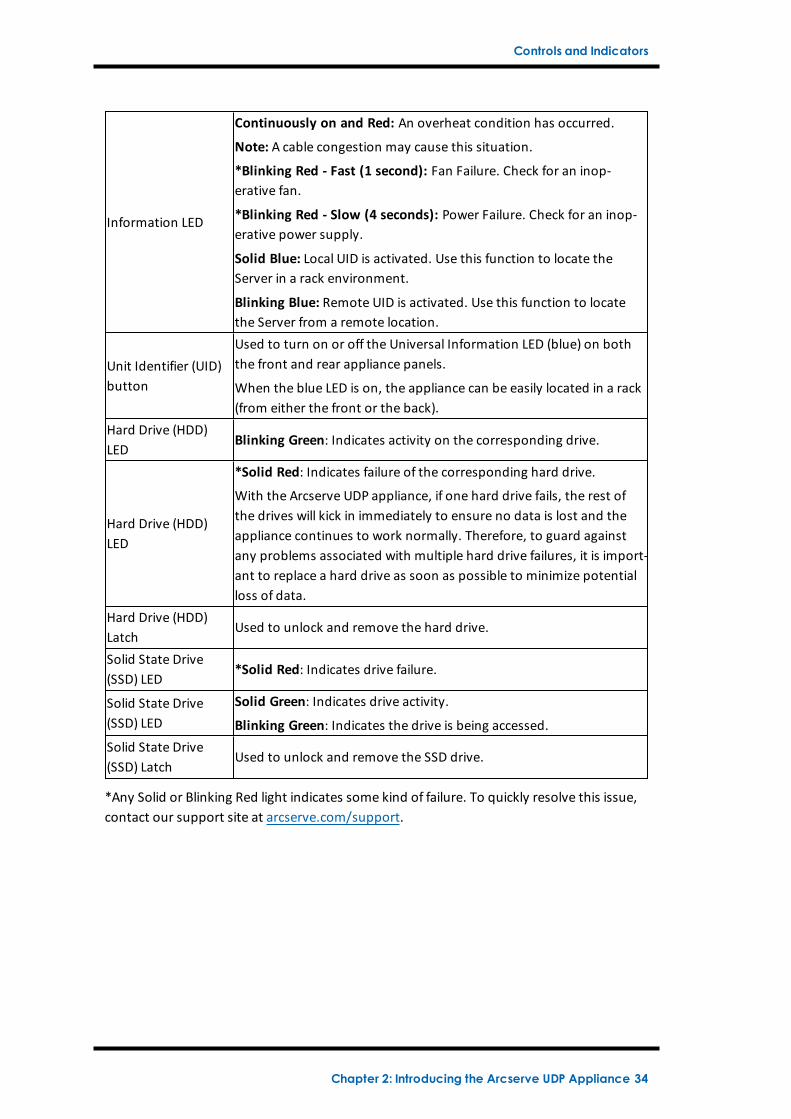
Information LED
Continuously on and Red: An overheat condition has occurred.
Note: A cable congestion may cause this situation.
*Blinking Red - Fast (1 second): Fan Failure. Check for an inop-erative fan.
*Blinking Red - Slow (4 seconds): Power Failure. Check for an inop-erative power supply.
Solid Blue: Local UID is activated. Use this function to locate theServer in a rack environment.
Blinking Blue: Remote UID is activated. Use this function to locatethe Server from a remote location.
Unit Identifier (UID)button
Used to turn on or off the Universal Information LED (blue) on boththe front and rear appliance panels.
When the blue LED is on, the appliance can be easily located in a rack(from either the front or the back).
Hard Drive (HDD)LED
Blinking Green: Indicates activity on the corresponding drive.
Hard Drive (HDD)LED
*Solid Red: Indicates failure of the corresponding hard drive.
With the Arcserve UDP appliance, if one hard drive fails, the rest ofthe drives will kick in immediately to ensure no data is lost and theappliance continues to work normally. Therefore, to guard againstany problems associated with multiple hard drive failures, it is import-ant to replace a hard drive as soon as possible to minimize potentialloss of data.
Hard Drive (HDD)Latch
Used to unlock and remove the hard drive.
Solid State Drive(SSD) LED
*Solid Red: Indicates drive failure.
Solid State Drive(SSD) LED
Solid Green: Indicates drive activity.
Blinking Green: Indicates the drive is being accessed.Solid State Drive(SSD) Latch
Used to unlock and remove the SSD drive.
*Any Solid or Blinking Red light indicates some kind of failure. To quickly resolve this issue,contact our support site at arcserve.com/support.
Chapter 2: Introducing the Arcserve UDP Appliance 34
Controls and Indicators
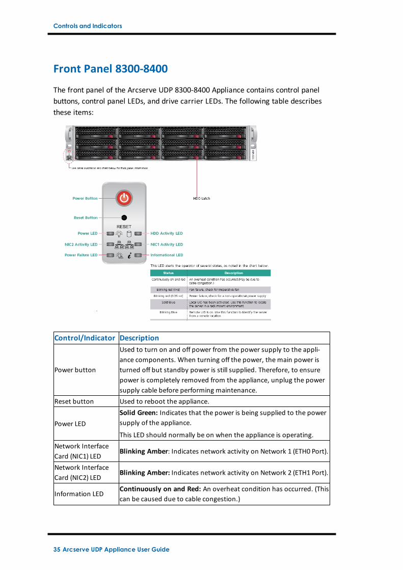
Front Panel 8300-8400
The front panel of the Arcserve UDP 8300-8400 Appliance contains control panelbuttons, control panel LEDs, and drive carrier LEDs. The following table describesthese items:
Control/Indicator Description
Power button
Used to turn on and off power from the power supply to the appli-ance components. When turning off the power, the main power isturned off but standby power is still supplied. Therefore, to ensurepower is completely removed from the appliance, unplug the powersupply cable before performing maintenance.
Reset button Used to reboot the appliance.
Power LEDSolid Green: Indicates that the power is being supplied to the powersupply of the appliance.
This LED should normally be on when the appliance is operating.Network InterfaceCard (NIC1) LED
Blinking Amber: Indicates network activity on Network 1 (ETH0 Port).
Network InterfaceCard (NIC2) LED
Blinking Amber: Indicates network activity on Network 2 (ETH1 Port).
Information LEDContinuously on and Red: An overheat condition has occurred. (Thiscan be caused due to cable congestion.)
35 Arcserve UDP Appliance User Guide
Controls and Indicators
*Blinking Red - Fast (1 second): Fan Failure. Check for an inop-erative fan.
*Blinking Red - Slow (4 seconds): Power Failure. Check for an inop-erative power supply.
Solid Blue: Local UID has been activated. Use this function to locatethe Server in a rack environment.
Blinking Blue: Remote UID has been activated. Use this function tolocate the Server from a remote location.
Power Failure LED Indicates a power supply module has failed.Hard Drive (HDD)LED
Blinking Green: Indicates activity on the corresponding drive.
Hard Drive (HDD)LED
*Solid Red: Indicates failure of the corresponding hard drive.
With the Arcserve UDP appliance, if one hard drive fails, the rest ofthe drives will kick in immediately to ensure no data is lost and theappliance continues to work normally. Therefore, to guard againstany problems associated with multiple hard drive failures, it is import-ant to replace a hard drive as soon as possible to minimize potentialloss of data.
Hard Drive (HDD)Latch
Used to unlock and remove the hard drive.
*Any Solid or Blinking Red light indicates some kind of failure. To quickly resolvethis issue, contact our support site at arcserve.com/support.
Chapter 2: Introducing the Arcserve UDP Appliance 36
Controls and Indicators
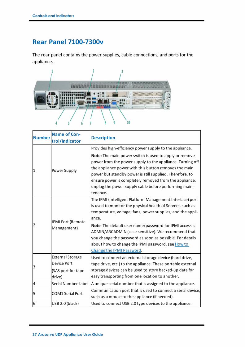
Rear Panel 7100-7300v
The rear panel contains the power supplies, cable connections, and ports for theappliance.
NumberName of Con-trol/Indicator
Description
1 Power Supply
Provides high-efficiency power supply to the appliance.
Note: The main power switch is used to apply or removepower from the power supply to the appliance. Turning offthe appliance power with this button removes the mainpower but standby power is still supplied. Therefore, toensure power is completely removed from the appliance,unplug the power supply cable before performing main-tenance.
2IPMI Port (RemoteManagement)
The IPMI (Intelligent Platform Management Interface) portis used to monitor the physical health of Servers, such astemperature, voltage, fans, power supplies, and the appli-ance.
Note: The default user name/password for IPMI access isADMIN/ARCADMIN (case-sensitive). We recommend thatyou change the password as soon as possible. For detailsabout how to change the IPMI password, see How toChange the IPMI Password.
3
External StorageDevice Port
(SAS port for tapedrive)
Used to connect an external storage device (hard drive,tape drive, etc.) to the appliance. These portable externalstorage devices can be used to store backed-up data foreasy transporting from one location to another.
4 Serial Number Label A unique serial number that is assigned to the appliance.
5 COM1 Serial PortCommunication port that is used to connect a serial device,such as a mouse to the appliance (if needed).
6 USB 2.0 (black) Used to connect USB 2.0 type devices to the appliance.
37 Arcserve UDP Appliance User Guide
Controls and Indicators
7 USB 3.0 (blue) Used to connect USB 3.0 type devices to the appliance.
8Network Data I/OPort 1
Used to transfer network data to and from the appliance.((ETH0 for Network 1)
9Network Data I/OPort 2
Used to transfer network data to and from the appliance.(ETH1 for Network 2)
10 VGA Connector Used to connect a monitor to the appliance (if needed).
Chapter 2: Introducing the Arcserve UDP Appliance 38
Controls and Indicators
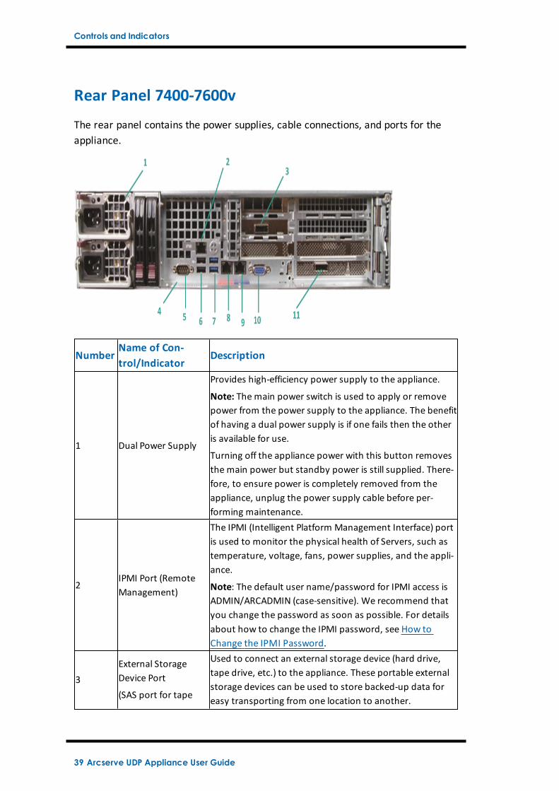
Rear Panel 7400-7600v
The rear panel contains the power supplies, cable connections, and ports for theappliance.
NumberName of Con-trol/Indicator
Description
1 Dual Power Supply
Provides high-efficiency power supply to the appliance.
Note: The main power switch is used to apply or removepower from the power supply to the appliance. The benefitof having a dual power supply is if one fails then the otheris available for use.
Turning off the appliance power with this button removesthe main power but standby power is still supplied. There-fore, to ensure power is completely removed from theappliance, unplug the power supply cable before per-forming maintenance.
2IPMI Port (RemoteManagement)
The IPMI (Intelligent Platform Management Interface) portis used to monitor the physical health of Servers, such astemperature, voltage, fans, power supplies, and the appli-ance.
Note: The default user name/password for IPMI access isADMIN/ARCADMIN (case-sensitive). We recommend thatyou change the password as soon as possible. For detailsabout how to change the IPMI password, see How toChange the IPMI Password.
3External StorageDevice Port
(SAS port for tape
Used to connect an external storage device (hard drive,tape drive, etc.) to the appliance. These portable externalstorage devices can be used to store backed-up data foreasy transporting from one location to another.
39 Arcserve UDP Appliance User Guide
Controls and Indicators
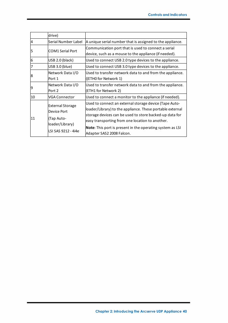
drive)4 Serial Number Label A unique serial number that is assigned to the appliance.
5 COM1 Serial PortCommunication port that is used to connect a serialdevice, such as a mouse to the appliance (if needed).
6 USB 2.0 (black) Used to connect USB 2.0 type devices to the appliance.7 USB 3.0 (blue) Used to connect USB 3.0 type devices to the appliance.
8Network Data I/OPort 1
Used to transfer network data to and from the appliance.((ETH0 for Network 1)
9Network Data I/OPort 2
Used to transfer network data to and from the appliance.(ETH1 for Network 2)
10 VGA Connector Used to connect a monitor to the appliance (if needed).
11
External StorageDevice Port
(Tap Auto-loader/Library)
LSI SAS 9212 - 4i4e
Used to connect an external storage device (Tape Auto-loader/Library) to the appliance. These portable externalstorage devices can be used to store backed-up data foreasy transporting from one location to another.
Note: This port is present in the operating system as LSIAdapter SAS2 2008 Falcon.
Chapter 2: Introducing the Arcserve UDP Appliance 40
Controls and Indicators
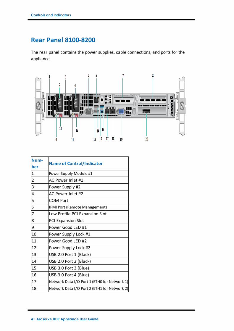
Rear Panel 8100-8200
The rear panel contains the power supplies, cable connections, and ports for theappliance.
Num-ber
Name of Control/Indicator
1 Power Supply Module #1
2 AC Power Inlet #13 Power Supply #24 AC Power Inlet #25 COM Port6 IPMI Port (RemoteManagement)
7 Low Profile PCI Expansion Slot8 PCI Expansion Slot9 Power Good LED #110 Power Supply Lock #111 Power Good LED #212 Power Supply Lock #213 USB 2.0 Port 1 (Black)14 USB 2.0 Port 2 (Black)15 USB 3.0 Port 3 (Blue)16 USB 3.0 Port 4 (Blue)17 Network Data I/O Port 1 (ETH0 for Network 1)
18 Network Data I/O Port 2 (ETH1 for Network 2)
41 Arcserve UDP Appliance User Guide
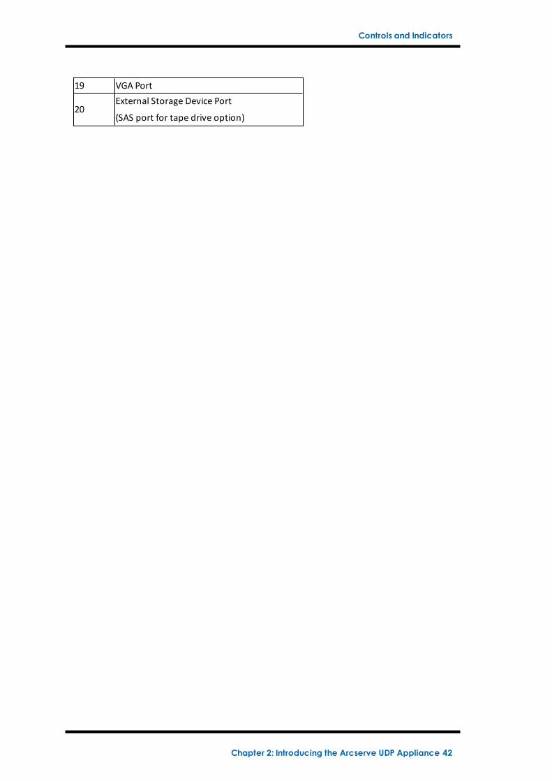
Controls and Indicators
19 VGA Port
20External Storage Device Port
(SAS port for tape drive option)
Chapter 2: Introducing the Arcserve UDP Appliance 42
Controls and Indicators
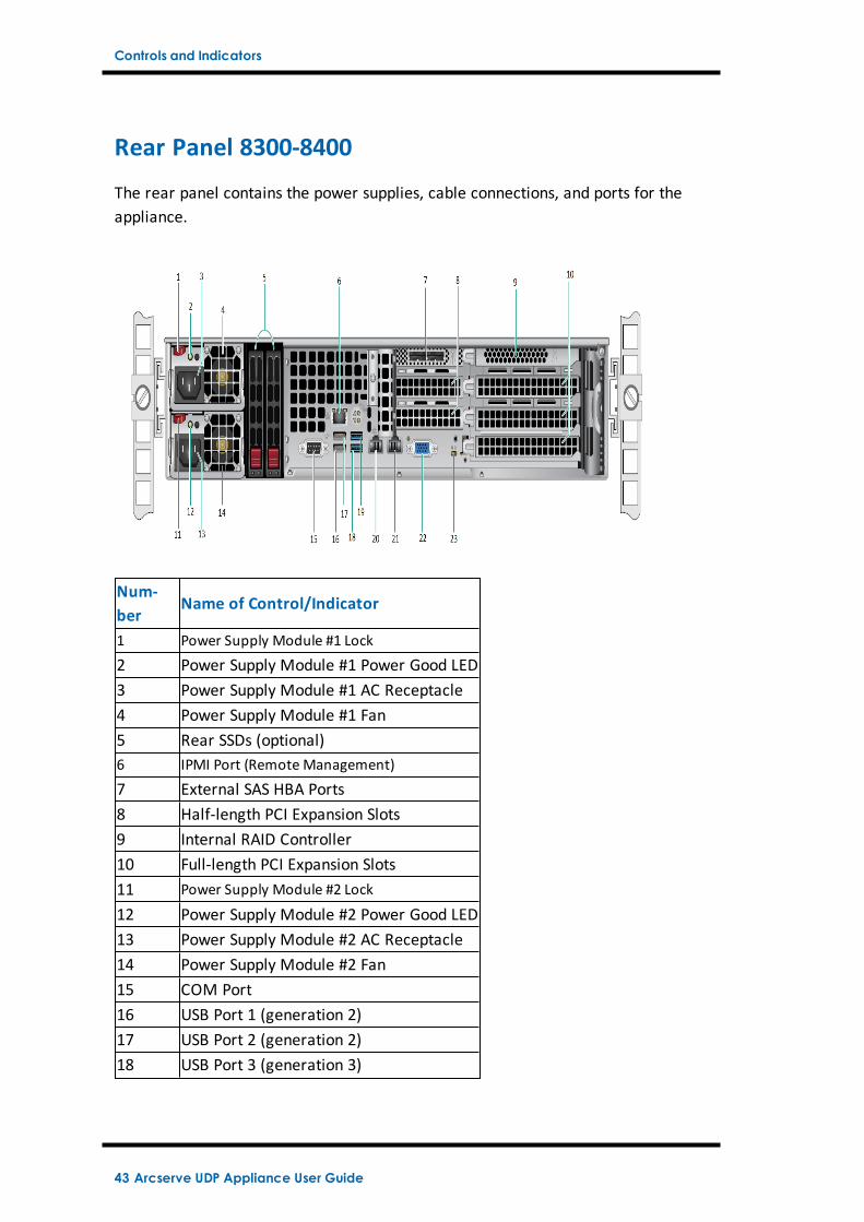
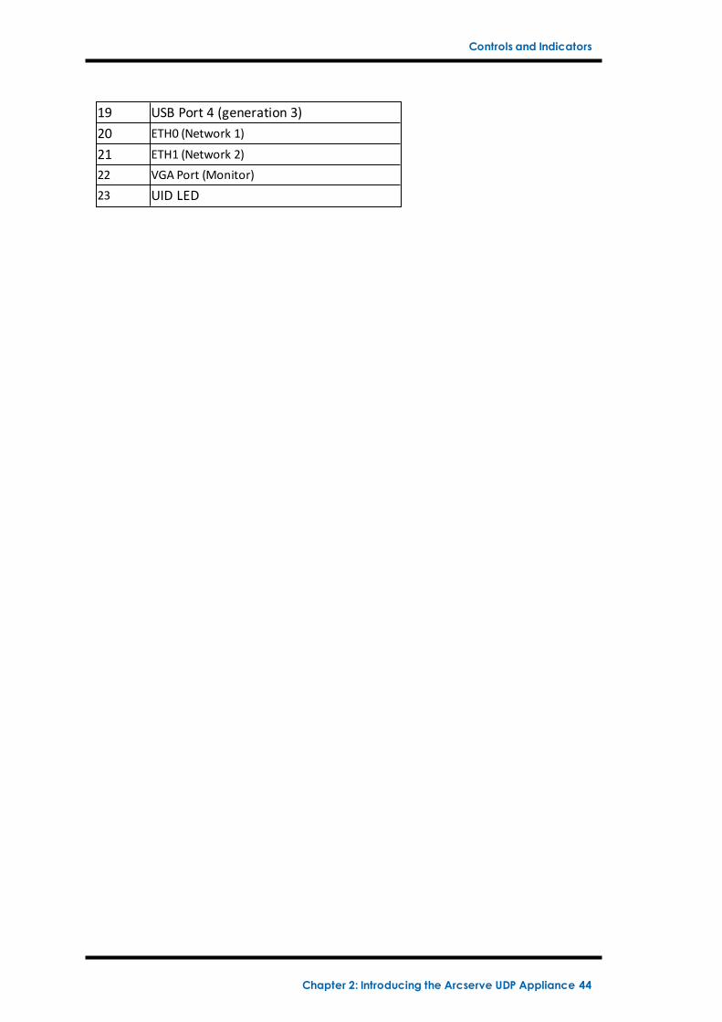
Rear Panel 8300-8400
The rear panel contains the power supplies, cable connections, and ports for theappliance.
Num-ber
Name of Control/Indicator
1 Power Supply Module #1 Lock
2 Power Supply Module #1 Power Good LED3 Power Supply Module #1 AC Receptacle4 Power Supply Module #1 Fan5 Rear SSDs (optional)6 IPMI Port (RemoteManagement)
7 External SAS HBA Ports8 Half-length PCI Expansion Slots9 Internal RAID Controller10 Full-length PCI Expansion Slots11 Power Supply Module #2 Lock
12 Power Supply Module #2 Power Good LED13 Power Supply Module #2 AC Receptacle14 Power Supply Module #2 Fan15 COM Port16 USB Port 1 (generation 2)17 USB Port 2 (generation 2)18 USB Port 3 (generation 3)
43 Arcserve UDP Appliance User Guide
Controls and Indicators
19 USB Port 4 (generation 3)20 ETH0 (Network 1)
21 ETH1 (Network 2)22 VGA Port (Monitor)23 UID LED
Chapter 2: Introducing the Arcserve UDP Appliance 44
Ports Used by the Appliance
Ports Used by the Appliance
The following list of tables provide information about ports that are used by Arc-serve UDP, Arcserve Backup, and the appliance for Linux support:
Arcserve UDP
Arcserve Backup
Appliance for Linux Support
45 Arcserve UDP Appliance User Guide
Ports Used by the Appliance
Arcserve UDP
This section contains the following topics:
Components installed on Microsoft Windows
Components installed on Linux
Production node protected by UDP Linux remotely
Chapter 2: Introducing the Arcserve UDP Appliance 46
Ports Used by the Appliance
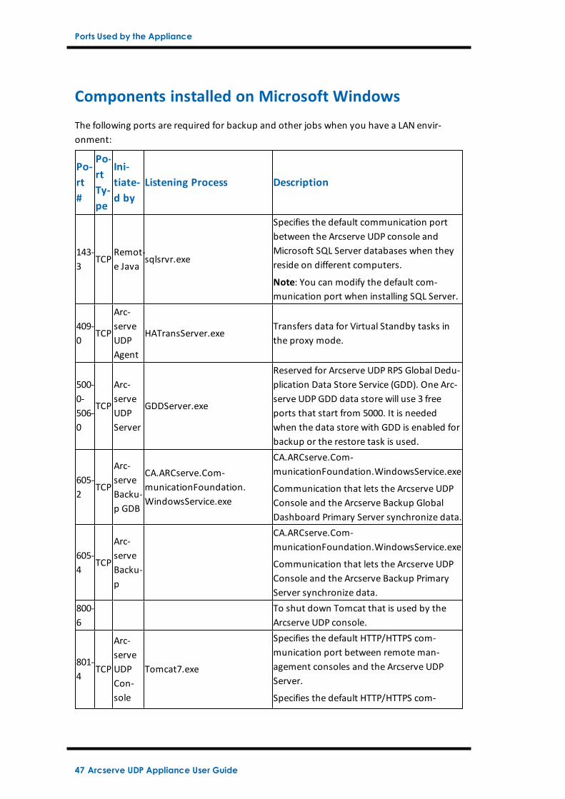
Components installed on Microsoft Windows
The following ports are required for backup and other jobs when you have a LAN envir-onment:
Po-rt#
Po-rtTy-pe
Ini-tiate-d by
Listening Process Description
143-3
TCPRemot-e Java
sqlsrvr.exe
Specifies the default communication portbetween the Arcserve UDP console andMicrosoft SQL Server databases when theyreside on different computers.
Note: You can modify the default com-munication port when installing SQL Server.
409-0
TCP
Arc-serveUDPAgent
HATransServer.exeTransfers data for Virtual Standby tasks inthe proxy mode.
500-0-506-0
TCP
Arc-serveUDPServer
GDDServer.exe
Reserved for Arcserve UDP RPS Global Dedu-plication Data Store Service (GDD). One Arc-serve UDP GDD data store will use 3 freeports that start from 5000. It is neededwhen the data store with GDD is enabled forbackup or the restore task is used.
605-2
TCP
Arc-serveBacku-p GDB
CA.ARCserve.Com-municationFoundation.WindowsService.exe
CA.ARCserve.Com-municationFoundation.WindowsService.exe
Communication that lets the Arcserve UDPConsole and the Arcserve Backup GlobalDashboard Primary Server synchronize data.
605-4
TCP
Arc-serveBacku-p
CA.ARCserve.Com-municationFoundation.WindowsService.exe
Communication that lets the Arcserve UDPConsole and the Arcserve Backup PrimaryServer synchronize data.
800-6
To shut down Tomcat that is used by theArcserve UDP console.
801-4
TCP
Arc-serveUDPCon-sole
Tomcat7.exe
Specifies the default HTTP/HTTPS com-munication port between remote man-agement consoles and the Arcserve UDPServer.
Specifies the default HTTP/HTTPS com-
47 Arcserve UDP Appliance User Guide
Ports Used by the Appliance
munication port between remote man-agement consoles and the Arcserve UDPAgent.
Note: You can modify the default com-munication port when you install the Arc-serve UDP components.
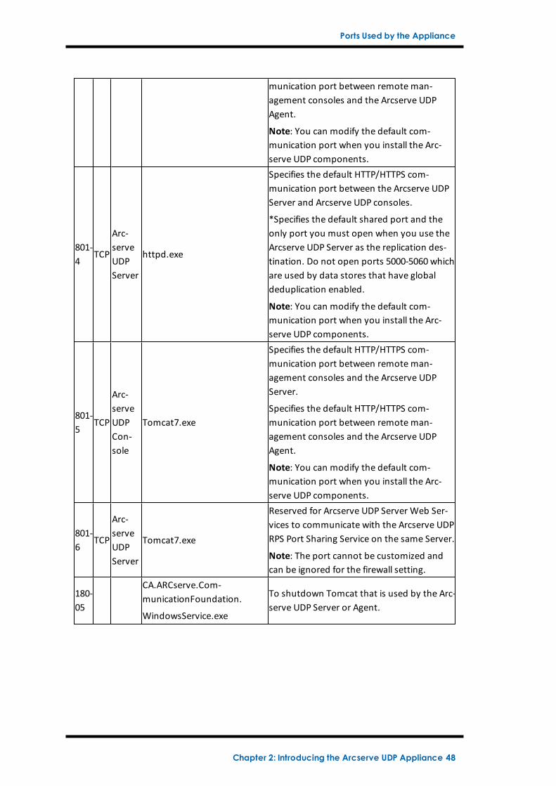
801-4
TCP
Arc-serveUDPServer
httpd.exe
Specifies the default HTTP/HTTPS com-munication port between the Arcserve UDPServer and Arcserve UDP consoles.
*Specifies the default shared port and theonly port you must open when you use theArcserve UDP Server as the replication des-tination. Do not open ports 5000-5060 whichare used by data stores that have globaldeduplication enabled.
Note: You can modify the default com-munication port when you install the Arc-serve UDP components.
801-5
TCP
Arc-serveUDPCon-sole
Tomcat7.exe
Specifies the default HTTP/HTTPS com-munication port between remote man-agement consoles and the Arcserve UDPServer.
Specifies the default HTTP/HTTPS com-munication port between remote man-agement consoles and the Arcserve UDPAgent.
Note: You can modify the default com-munication port when you install the Arc-serve UDP components.
801-6
TCP
Arc-serveUDPServer
Tomcat7.exe
Reserved for Arcserve UDP Server Web Ser-vices to communicate with the Arcserve UDPRPS Port Sharing Service on the same Server.
Note: The port cannot be customized andcan be ignored for the firewall setting.
180-05
CA.ARCserve.Com-municationFoundation.
WindowsService.exe
To shutdown Tomcat that is used by the Arc-serve UDP Server or Agent.
Chapter 2: Introducing the Arcserve UDP Appliance 48
Ports Used by the Appliance
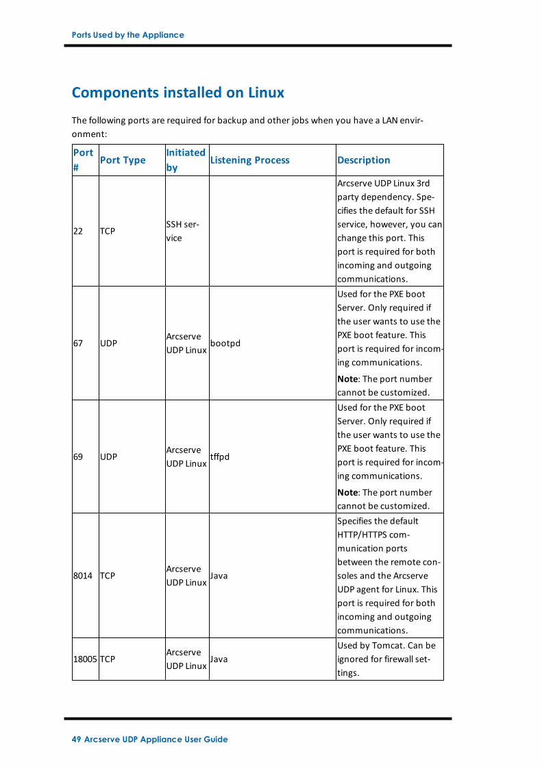
Components installed on Linux
The following ports are required for backup and other jobs when you have a LAN envir-onment:
Port#
Port TypeInitiatedby
Listening Process Description
22 TCPSSH ser-vice
Arcserve UDP Linux 3rdparty dependency. Spe-cifies the default for SSHservice, however, you canchange this port. Thisport is required for bothincoming and outgoingcommunications.
67 UDPArcserveUDP Linux
bootpd
Used for the PXE bootServer. Only required ifthe user wants to use thePXE boot feature. Thisport is required for incom-ing communications.
Note: The port numbercannot be customized.
69 UDPArcserveUDP Linux
tffpd
Used for the PXE bootServer. Only required ifthe user wants to use thePXE boot feature. Thisport is required for incom-ing communications.
Note: The port numbercannot be customized.
8014 TCPArcserveUDP Linux
Java
Specifies the defaultHTTP/HTTPS com-munication portsbetween the remote con-soles and the ArcserveUDP agent for Linux. Thisport is required for bothincoming and outgoingcommunications.
18005 TCPArcserveUDP Linux
JavaUsed by Tomcat. Can beignored for firewall set-tings.
49 Arcserve UDP Appliance User Guide
Ports Used by the Appliance
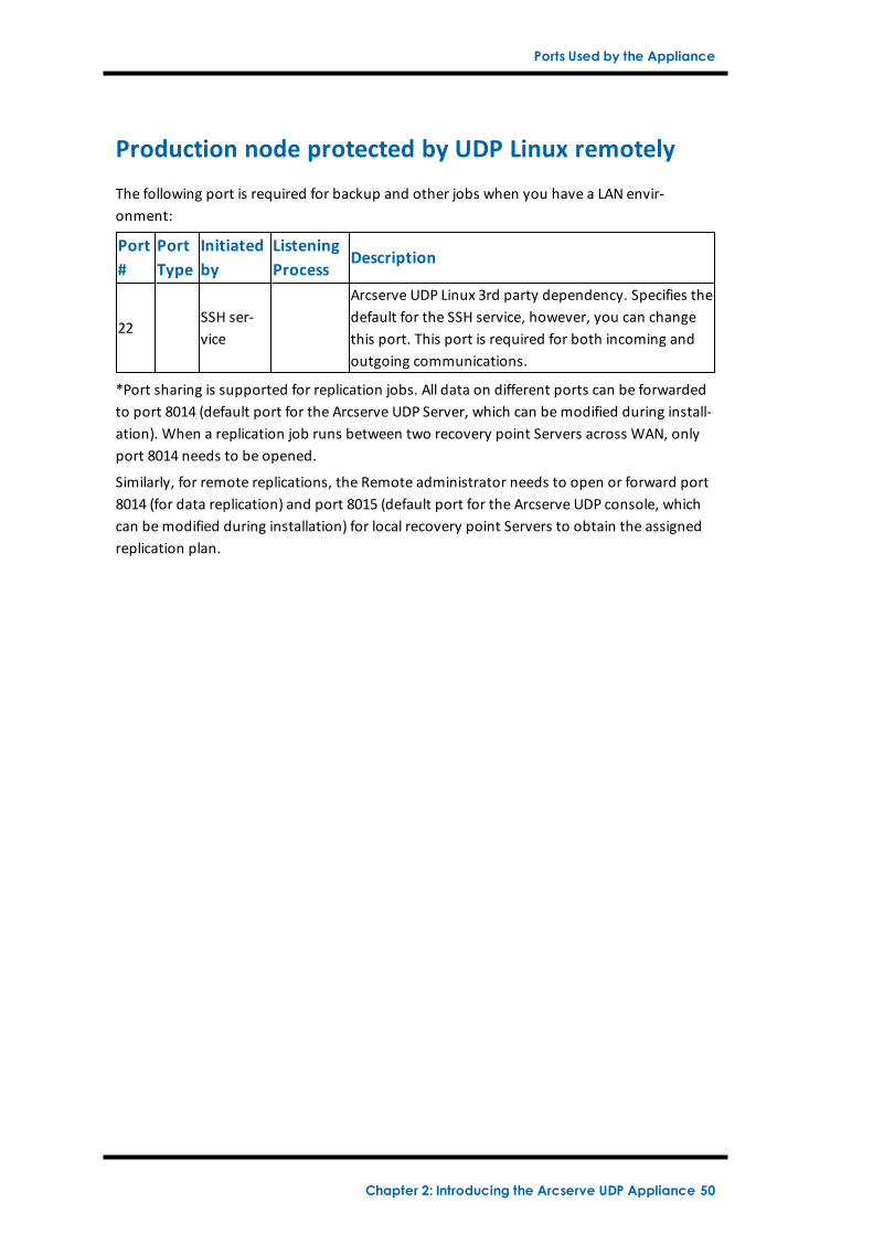
Production node protected by UDP Linux remotely
The following port is required for backup and other jobs when you have a LAN envir-onment:
Port#
PortType
Initiatedby
ListeningProcess
Description
22SSH ser-vice
Arcserve UDP Linux 3rd party dependency. Specifies thedefault for the SSH service, however, you can changethis port. This port is required for both incoming andoutgoing communications.
*Port sharing is supported for replication jobs. All data on different ports can be forwardedto port 8014 (default port for the Arcserve UDP Server, which can be modified during install-ation). When a replication job runs between two recovery point Servers across WAN, onlyport 8014 needs to be opened.
Similarly, for remote replications, the Remote administrator needs to open or forward port8014 (for data replication) and port 8015 (default port for the Arcserve UDP console, whichcan be modified during installation) for local recovery point Servers to obtain the assignedreplication plan.
Chapter 2: Introducing the Arcserve UDP Appliance 50
Ports Used by the Appliance
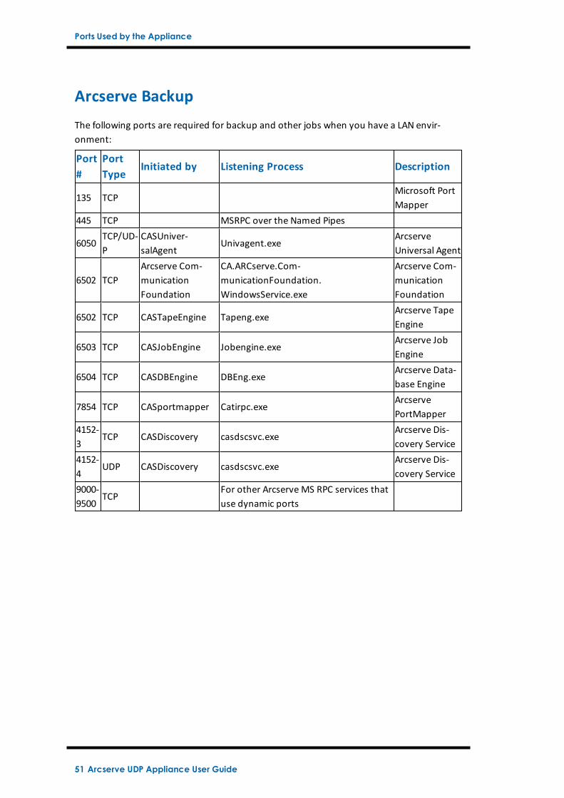
Arcserve Backup
The following ports are required for backup and other jobs when you have a LAN envir-onment:
Port#
PortType
Initiated by Listening Process Description
135 TCPMicrosoft PortMapper
445 TCP MSRPC over the Named Pipes
6050TCP/UD-P
CASUniver-salAgent
Univagent.exeArcserveUniversal Agent
6502 TCPArcserve Com-municationFoundation
CA.ARCserve.Com-municationFoundation.WindowsService.exe
Arcserve Com-municationFoundation
6502 TCP CASTapeEngine Tapeng.exeArcserve TapeEngine
6503 TCP CASJobEngine Jobengine.exeArcserve JobEngine
6504 TCP CASDBEngine DBEng.exeArcserve Data-base Engine
7854 TCP CASportmapper Catirpc.exeArcservePortMapper
4152-3
TCP CASDiscovery casdscsvc.exeArcserve Dis-covery Service
4152-4
UDP CASDiscovery casdscsvc.exeArcserve Dis-covery Service
9000-9500
TCPFor other Arcserve MS RPC services thatuse dynamic ports
51 Arcserve UDP Appliance User Guide
Ports Used by the Appliance
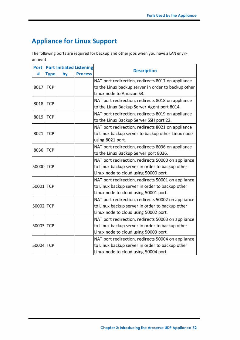
Appliance for Linux Support
The following ports are required for backup and other jobs when you have a LAN envir-onment:
Port#
PortType
Initiatedby
ListeningProcess
Description
8017 TCPNAT port redirection, redirects 8017 on applianceto the Linux backup server in order to backup otherLinux node to Amazon S3.
8018 TCPNAT port redirection, redirects 8018 on applianceto the Linux Backup Server Agent port 8014.
8019 TCPNAT port redirection, redirects 8019 on applianceto the Linux Backup Server SSH port 22.
8021 TCPNAT port redirection, redirects 8021 on applianceto Linux backup server to backup other Linux nodeusing 8021 port.
8036 TCPNAT port redirection, redirects 8036 on applianceto the Linux Backup Server port 8036.
50000 TCPNAT port redirection, redirects 50000 on applianceto Linux backup server in order to backup otherLinux node to cloud using 50000 port.
50001 TCPNAT port redirection, redirects 50001 on applianceto Linux backup server in order to backup otherLinux node to cloud using 50001 port.
50002 TCPNAT port redirection, redirects 50002 on applianceto Linux backup server in order to backup otherLinux node to cloud using 50002 port.
50003 TCPNAT port redirection, redirects 50003 on applianceto Linux backup server in order to backup otherLinux node to cloud using 50003 port.
50004 TCPNAT port redirection, redirects 50004 on applianceto Linux backup server in order to backup otherLinux node to cloud using 50004 port.
Chapter 2: Introducing the Arcserve UDP Appliance 52
Chapter 3: Installing the Arcserve UDP ApplianceThis section contains the following topics:
How to Install Arcserve Backup r17.5 54
How to Install 8100-8200 Series Appliance 56
How to Install 8300-8400 Series Appliance 57
53 Arcserve UDP Appliance User Guide
How to Install Arcserve Backup r17.5
How to Install Arcserve Backup r17.5
Arcserve Backup r17.5 is not pre-installed on the appliance. You can install Arc-serve Backup r17.5 using a script called “InstallASBU.bat” located on your desktop.
Follow these steps:
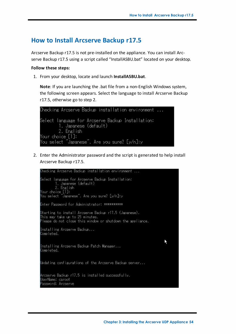
1. From your desktop, locate and launch InstallASBU.bat.
Note: If you are launching the .bat file from a non-English Windows system,the following screen appears. Select the language to install Arcserve Backupr17.5, otherwise go to step 2.
2. Enter the Administrator password and the script is generated to help installArcserve Backup r17.5.
Chapter 3: Installing the Arcserve UDP Appliance 54
How to Install Arcserve Backup r17.5
After installation completes, the Arcserve Backup icon is added to your desktop.You can now log into Arcserve Backup with the following credentials:
User Name = caroot
Password = Arcserve
55 Arcserve UDP Appliance User Guide
How to Install 8100-8200 Series Appliance
How to Install 8100-8200 Series Appliance
The appliance is intended for installation in restricted areas only. Initial setup andmaintenance should be performed by qualified personnel.
For the complete installation process, see Appliance Installation of 8100-8200.
Chapter 3: Installing the Arcserve UDP Appliance 56
How to Install 8300-8400 Series Appliance
How to Install 8300-8400 Series Appliance
The appliance is intended for installation in restricted areas only. Initial setup andmaintenance should be performed by qualified personnel.
For the complete installation process, see Appliance Installation of 8300-8400.
57 Arcserve UDP Appliance User Guide
Chapter 4: Understanding Network ConfigurationThis section contains the following topics:
How to Configure the NIC Teaming Process 59
How to Disable DHCP Server 61
How to Understand the Network Configuration on the UDP Appliance 62
How to Configure IP Address for the preinstalled Linux Backup Server 66
How to Enable Round Robin on the DNS Server to Balance Load 68
Chapter 4: Understanding Network Configuration 58
How to Configure the NIC Teaming Process
How to Configure the NIC Teaming Process
The Arcserve UDP Appliance contains built-in Ethernet ports. To use these ports, anEthernet NIC teaming needs to be configured. NIC Teaming allows multiple net-work adapters placed into a team for bandwidth aggregation and traffic failover tomaintain connectivity in the event of a network component failure.
To configure a working NIC Team, a network switch supporting the link aggregationis required. Consult your network switch vendor and Microsoft Windows Con-figuration document to configure the NIC Team.
After the network switch is configured, follow these steps:
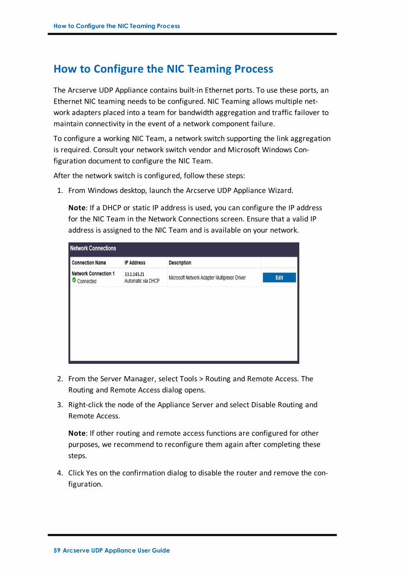
1. From Windows desktop, launch the Arcserve UDP Appliance Wizard.
Note: If a DHCP or static IP address is used, you can configure the IP addressfor the NIC Team in the Network Connections screen. Ensure that a valid IPaddress is assigned to the NIC Team and is available on your network.
2. From the Server Manager, select Tools > Routing and Remote Access. TheRouting and Remote Access dialog opens.
3. Right-click the node of the Appliance Server and select Disable Routing andRemote Access.
Note: If other routing and remote access functions are configured for otherpurposes, we recommend to reconfigure them again after completing thesesteps.
4. Click Yes on the confirmation dialog to disable the router and remove the con-figuration.
59 Arcserve UDP Appliance User Guide
How to Configure the NIC Teaming Process
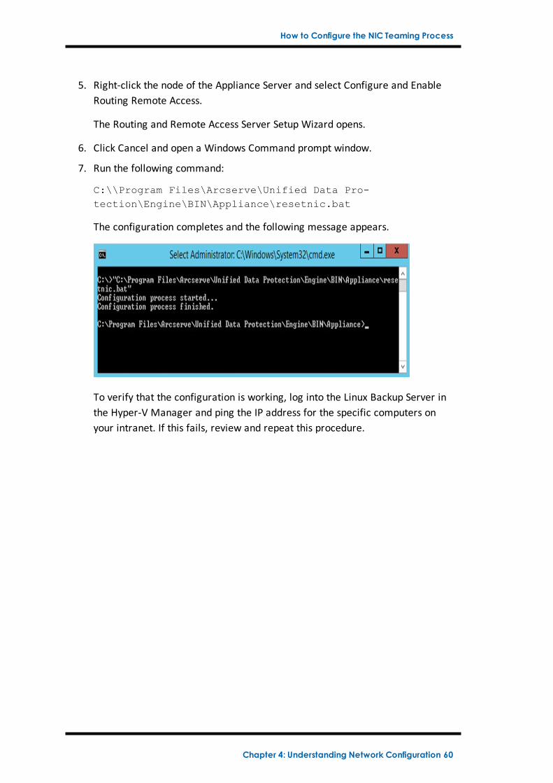
5. Right-click the node of the Appliance Server and select Configure and EnableRouting Remote Access.
The Routing and Remote Access Server Setup Wizard opens.
6. Click Cancel and open a Windows Command prompt window.
7. Run the following command:
C:\\Program Files\Arcserve\Unified Data Pro-tection\Engine\BIN\Appliance\resetnic.bat
The configuration completes and the following message appears.
To verify that the configuration is working, log into the Linux Backup Server inthe Hyper-V Manager and ping the IP address for the specific computers onyour intranet. If this fails, review and repeat this procedure.
Chapter 4: Understanding Network Configuration 60
How to Disable DHCP Server
How to Disable DHCP Server
DHCP Server is enabled by default on the Appliance. The DHCP Server works onlyon Hyper-V Virtual Ethernet Adapter – LinuxBkpSvr on the Appliance to make surethat the preinstalled Linux Backup Server can get the IP and communicate with theAppliance and does not impact the production network environment.
To disable DHCP Server, follow these steps:
1. Open file C:\Program Files\Arcserve\Unified Data Pro-tection\Engine\BIN\Appliance\Configuration\Appliance.properties
2. Modify the file to DHCP_ENABLE=false. The Appliance.properties appearsas below:
DHCP_ENABLE=false
AdapterName=LinuxBkpSvr
Appliance_IPAddress=192.168.10.1
Linux_IPAddress=192.168.10.2
3. Save the file.
4. Delete the file C:\Program Files\Arcserve\Unified Data Pro-tection\Engine\BIN\Appliance\dhcpdone.flag.
5. Run C:\Program Files\Arcserve\Unified Data Pro-tection\Engine\BIN\Appliance\resetdhcp.ps1 to disable the DHCP Server ser-vice as below from dos command line:
C:\Program Files\Arcserve\Unified Data Pro-tection\Engine\BIN\Appliance>powershell .\resetdhcp.ps1
61 Arcserve UDP Appliance User Guide
How to Understand the Network Configuration on the UDP Appliance
How to Understand the Network Configuration onthe UDP Appliance
The purpose of network configuration on the Appliance ensures the build-in LinuxBackup Server (virtual name in Hyper-V Manager: Linux-BackupSvr) can workbehind NAT. So that:
User does not need to change the hostname of the build-in Linux.
User saves an IP on the network for the Linux Backup Server.
The Linux Backup Server can connect to any machine on the public network.
Any machine on the public network can only connect to the Linux Backup Serverthrough the Appliance Servers special port.
Network Configuration Detail:
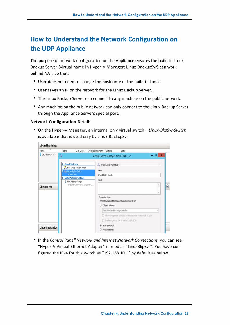
On the Hyper-V Manager, an internal only virtual switch – Linux-BkpSvr-Switchis available that is used only by Linux-BackupSvr.
In the Control Panel\Network and Internet\Network Connections, you can see“Hyper-V Virtual Ethernet Adapter” named as “LinuxBkpSvr”. You have con-figured the IPv4 for this switch as “192.168.10.1” by default as below.
Chapter 4: Understanding Network Configuration 62
How to Understand the Network Configuration on the UDP Appliance
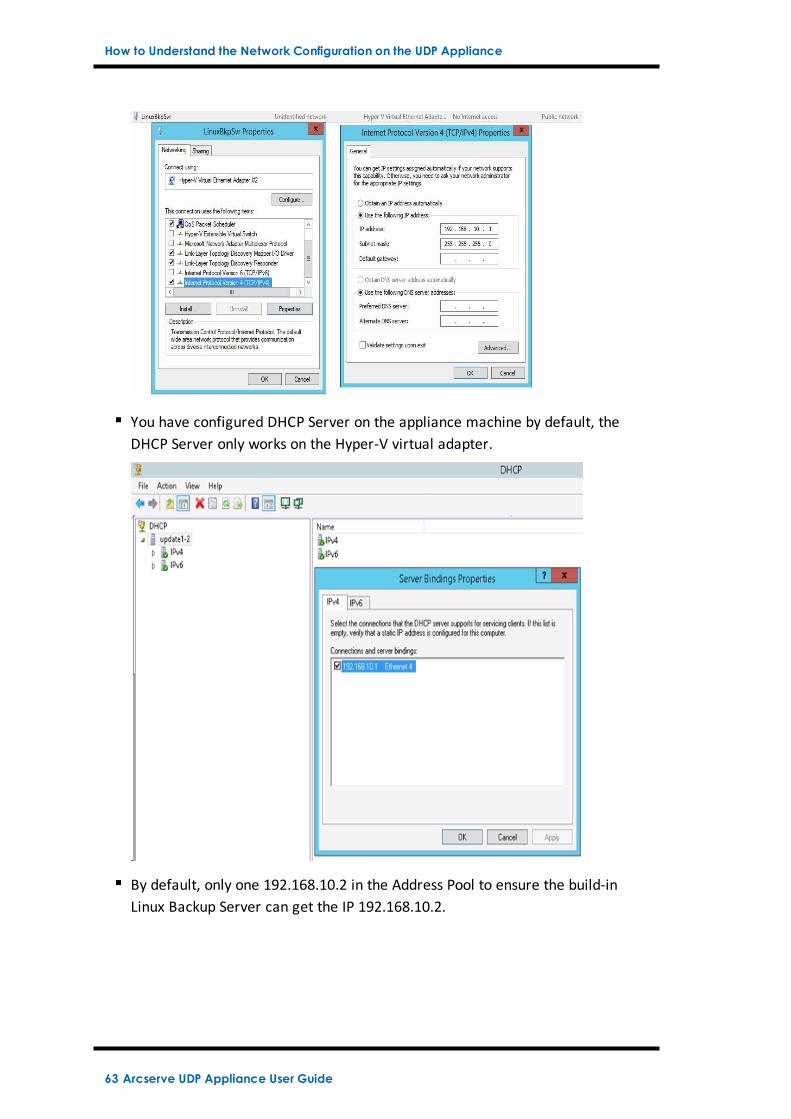
You have configured DHCP Server on the appliance machine by default, theDHCP Server only works on the Hyper-V virtual adapter.
By default, only one 192.168.10.2 in the Address Pool to ensure the build-inLinux Backup Server can get the IP 192.168.10.2.
63 Arcserve UDP Appliance User Guide
How to Understand the Network Configuration on the UDP Appliance
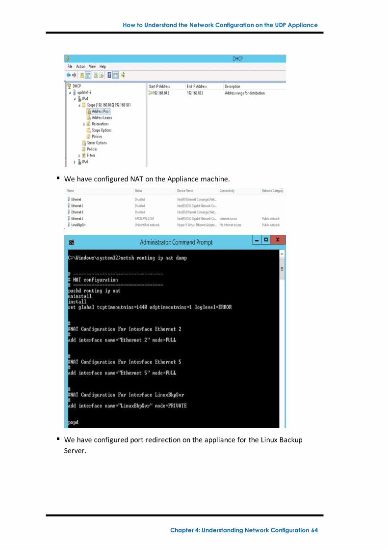
We have configured NAT on the Appliance machine.
We have configured port redirection on the appliance for the Linux BackupServer.
Chapter 4: Understanding Network Configuration 64
How to Understand the Network Configuration on the UDP Appliance
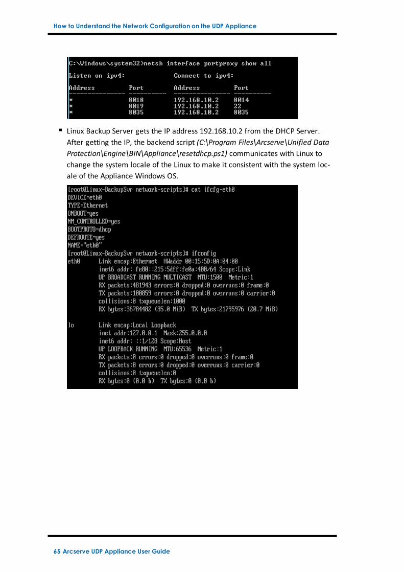
Linux Backup Server gets the IP address 192.168.10.2 from the DHCP Server.After getting the IP, the backend script (C:\Program Files\Arcserve\Unified DataProtection\Engine\BIN\Appliance\resetdhcp.ps1) communicates with Linux tochange the system locale of the Linux to make it consistent with the system loc-ale of the Appliance Windows OS.
65 Arcserve UDP Appliance User Guide
How to Configure IP Address for the preinstalled Linux Backup Server
How to Configure IP Address for the preinstalledLinux Backup Server
For the preinstalled Linux Backup Server, by default, the backup server uses IP192.168.10.2 to communicate with the Appliance Server. Please refer to the net-work configuration introduction for preinstalled Linux Backup Server as for how pre-installed Linux Backup Server communicate with Appliance Server.
To specify the IP address for the preinstalled Linux Backup Server, follow thesesteps:
1. Open file C:\Program Files\Arcserve\Unified Data Pro-tection\Engine\BIN\Appliance\Configuration\Appliance.properties.
2. Change the IP address of Appliance_IPAddress and Linux_IPAddress. Forexample, set Appliance_IPAddress as 192.168.100.1 and Linux_IPAddress as192.168.100.2.
Note:
The IP address of Appliance_IPAddress sets to the network interfaceLinuxBkpSvr (Hyper-V Virtual Ethernet Adapter) used to communicatewith this preinstalled Linux Backup Server.
The IP address of Linux_IPAddress is set to the preinstalled LinuxBackup Server.
Please ensure “Appliance_IPAddress” and “Linux_IPAddress” use the IPaddress of the same sub network.
Here is the file after modified:
DHCP_ENABLE=true
AdapterName=LinuxBkpSvr
Appliance_IPAddress=192.168.100.1
Linux_IPAddress=192.168.100.2
3. Save the file.
4. Delete the file C:\Program Files\Arcserve\Unified Data Pro-tection\Engine\BIN\Appliance\dhcpdone.flag.
5. Run C:\Program Files\Arcserve\Unified Data Pro-tection\Engine\BIN\Appliance\resetdhcp.ps1 to reset the IP address for net-work interface LinuxBkpSvr and the preinstalled Linux Backup Server.
Note:
Chapter 4: Understanding Network Configuration 66
How to Configure IP Address for the preinstalled Linux Backup Server
The preinstalled Linux Backup Server will shut down and restart during theprocess if you change the Linux_IPAddress.
Run the command prompt and enter the following command:
C:\Program Files\Arcserve\Unified Data Pro-tection\Engine\BIN\Appliance>powershell .\resetdhcp.ps1
67 Arcserve UDP Appliance User Guide
How to Enable Round Robin on the DNS Server to Balance Load
How to Enable Round Robin on the DNS Server to Bal-ance Load
The Microsoft DNS Server supports round robin, which is a technique used for bal-ancing the load between servers. This feature enables DNS to send both IPaddresses when a query is received for myserver.mydomain.com. The client (orResolver) always uses the first one. The next time when DNS receives a query forthis name, the order of the IP address list is changed using round robin method (theaddress that was first in the previous list is last in the new list). Round Robin ofname records is not supported because only one canonical name is allowed for anyone alias.
For more details, refer to Microsoft KB 168321.
In the Appliance, you can add record(s) for all the IPv4 address to the DomainName Service(DNS) Server to get load balance among the network interfaces.
For more information on load balancing between servers, refer to RFC 1794.
Chapter 4: Understanding Network Configuration 68
Chapter 5: Upgrading Arcserve UDP on the ApplianceThis section contains the following topics:
How to Apply a License After Upgrading Arcserve Software 70
Upgrade Sequence on the Arcserve UDP Appliance 71
Upgrade Sequence for UDP Console, RPS, and Agent 77
Chapter 5: Upgrading Arcserve UDP on the Appliance 69
How to Apply a License After Upgrading Arcserve Software
How to Apply a License After Upgrading Arcserve Soft-ware
After upgrading Arcserve UDP to v6.5 or upgrading Arcserve Backup to r17.5, theoriginal license key on the Arcserve UDP appliance will not work. To obtain the newlicense keys for Arcserve Unified Data Protection v6.5 and Arcserve Backup r17.5,contact your account representative.
For more details about adding a license key for Arcserve UDP, see ArcserveProduct Activation topic from the Arcserve Unified Data Protection SolutionsGuide.
For more details about adding a license key for Arcserve UDP, see Apply ArcserveBackup Component Licenses from the Arcserve Backup Administration Guide.
70 Arcserve UDP Appliance User Guide
Upgrade Sequence on the Arcserve UDP Appliance
Upgrade Sequence on the Arcserve UDP Appliance
The upgrade from Arcserve UDP Appliance v5.0 to Arcserve UDP v6.5 could involveone of the following sequences:
Upgrade Arcserve UDP
Upgrade the Arcserve UDP Appliance that performs as Arcserve UDP Con-sole and RPS
Upgrade the Arcserve UDP Appliance that performs as Arcserve UDP RPSonly
Upgrade Steps When Two or More Arcserve UDP Appliances Are Used in theEnvironment
Upgrade the Arcserve UDP Linux Agent on the Arcserve UDP Appliance
Upgrade the Arcserve Backup on the Arcserve UDP Appliance
Upgrade Sequence for UDP Console, RPS, and Agent
Chapter 5: Upgrading Arcserve UDP on the Appliance 71
Upgrade Sequence on the Arcserve UDP Appliance
Upgrade the Arcserve UDP Appliance that performsas Arcserve UDP Console and RPS
Upgrade this Arcserve UDP Appliance, then follow up the upgrade sequencedescribed to upgrade the environment.
72 Arcserve UDP Appliance User Guide
Upgrade Sequence on the Arcserve UDP Appliance
Upgrade the Arcserve UDP Appliance that performsas Arcserve UDP RPS only
Upgrade the complete productive environment. For details, refer to the upgradesequence.
Chapter 5: Upgrading Arcserve UDP on the Appliance 73
Upgrade Sequence on the Arcserve UDP Appliance
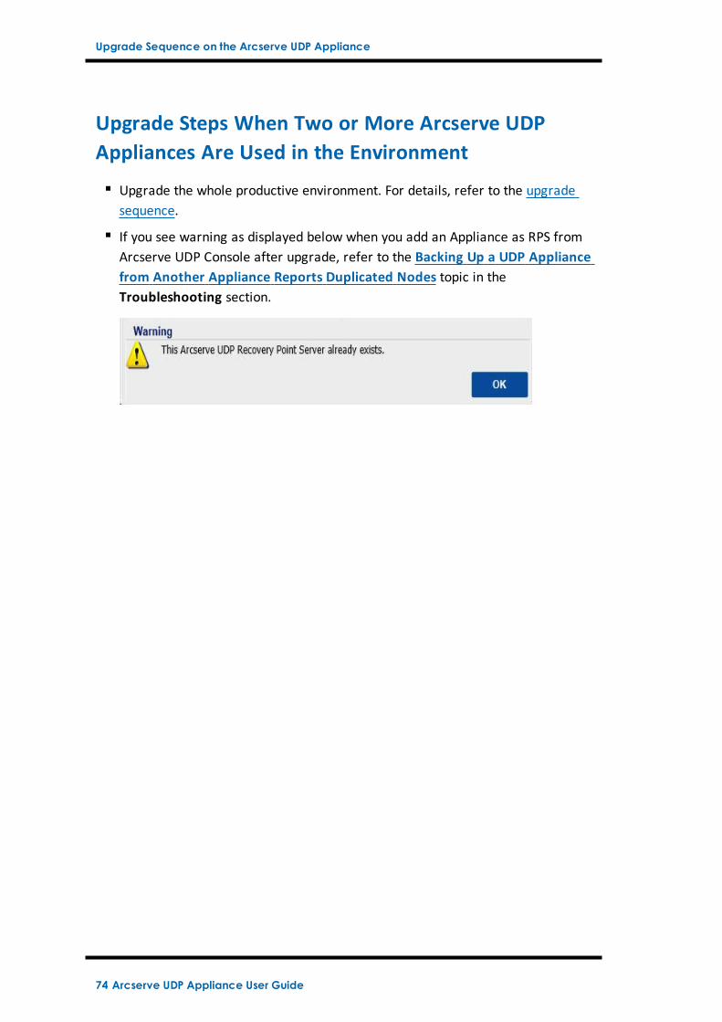
Upgrade Steps When Two or More Arcserve UDPAppliances Are Used in the Environment
Upgrade the whole productive environment. For details, refer to the upgradesequence.
If you see warning as displayed below when you add an Appliance as RPS fromArcserve UDP Console after upgrade, refer to the Backing Up a UDP Appliancefrom Another Appliance Reports Duplicated Nodes topic in theTroubleshooting section.
74 Arcserve UDP Appliance User Guide
Upgrade Sequence on the Arcserve UDP Appliance
Upgrade the Arcserve UDP Linux Agent on the Arc-serve UDP Appliance
First, upgrade the Arcserve UDP Console which manages the Linux BackupServer environment;
Then, upgrade the Linux Backup Server on the Arcserve UDP Appliance. Fordetails, refer to the Arcserve Unified Data Protection Agent for Linux OnlineHelp.
Chapter 5: Upgrading Arcserve UDP on the Appliance 75
Upgrade Sequence on the Arcserve UDP Appliance
Upgrade the Arcserve Backup on the Arcserve UDPAppliance
Refer to the Arcserve Backup Implementation Guide to complete upgrade on theArcserve UDP Appliance.
76 Arcserve UDP Appliance User Guide
Upgrade Sequence for UDP Console, RPS, and Agent
Upgrade Sequence for UDP Console, RPS, and Agent
Based on the Backward Compatibility Support Policy, plan your upgrade in the fol-lowing sequence to ensure the upgrade works smoothly:
1. Upgrade Arcserve UDP Console.
2. Upgrade Arcserve UDP RPS (DR site).
3. Upgrade Arcserve UDP RPS (Data Center).
4. Upgrade Arcserve UDP Agentless Proxy, some Agents in Data Center.
5. Upgrade Arcserve UDP RPS (Remote site).
6. Upgrade Arcserve UDP Agentless Proxy and some Agents at the remote site.
Note: Repeat Step 5 and 6 for each remote location.
7. Upgrade Arcserve UDP Virtual Standby Monitor.
Note: Per the replication backward support policy, always upgrade the target RPSbefore the source RPS.
Chapter 5: Upgrading Arcserve UDP on the Appliance 77
Chapter 6: Configuring the Arcserve UDP ApplianceThis section contains the following topics:
How to Configure Network Settings for a UDP Appliance 79
Overview of Creating a Plan Using the UDP ApplianceWizard 83
How to Set up the Arcserve UDP Appliance and Create Plans 84
Additional Information on Adding Nodes to a Plan 93
Configure UDP Appliance as Gateway 102
Clear Configuration and Apply Appliance Factory Reset 103
Apply Arcserve UDP Factory Reset Using Boot Option 105
How to Activate Arcserve Product on the Appliance 108
Chapter 6: Configuring the Arcserve UDP Appliance 78
How to Configure Network Settings for a UDP Appliance
How to Configure Network Settings for a UDP Appli-ance
To manage the Arcserve UDP appliance, the first step is to have the appliance inyour network. For that, you need to assign a hostname to the appliance and thenconfigure network ports.
Follow these steps:
1. After you power on the appliance, the Settings screen for the MicrosoftLicense terms opens. Read and accept the terms.
2. The UDP End User License Agreement dialog opens. Read and accept thelicense agreement and click Next.
3. Enter a hostname for the appliance. Assigning a name helps identify the appli-ance on your network.
To make your appliance a member of a domain in your network, click theAdd this Arcserve UDP Appliance to a domain option and specify thedomain, user name, and password.
Note: The Domain, Username, and Password fields is displayed when theoption is selected.
79 Arcserve UDP Appliance User Guide
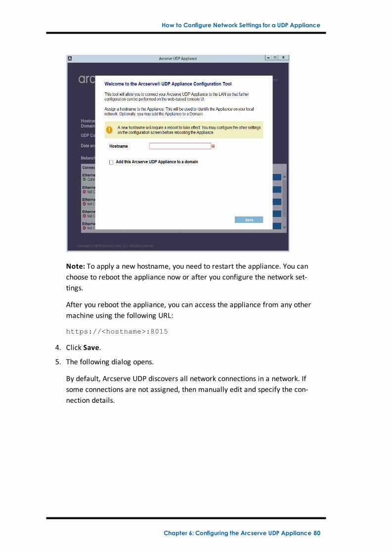
How to Configure Network Settings for a UDP Appliance
Note: To apply a new hostname, you need to restart the appliance. You canchoose to reboot the appliance now or after you configure the network set-tings.
After you reboot the appliance, you can access the appliance from any othermachine using the following URL:
https://<hostname>:8015
4. Click Save.
5. The following dialog opens.
By default, Arcserve UDP discovers all network connections in a network. Ifsome connections are not assigned, then manually edit and specify the con-nection details.
Chapter 6: Configuring the Arcserve UDP Appliance 80
How to Configure Network Settings for a UDP Appliance
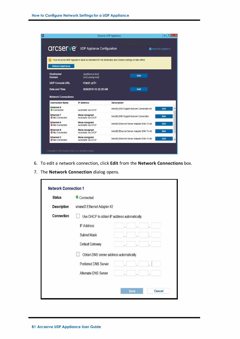
6. To edit a network connection, click Edit from the Network Connections box.
7. The Network Connection dialog opens.
81 Arcserve UDP Appliance User Guide
How to Configure Network Settings for a UDP Appliance
8. Modify the IP address, subnet mask, and default gateway values as requiredand click Save.
Note: Optionally, you can also modify the hostname, domain, date, and time.
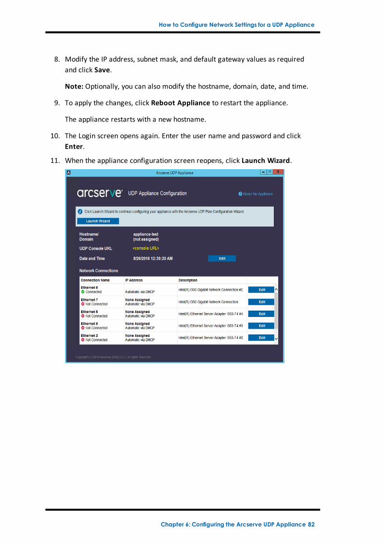
9. To apply the changes, click Reboot Appliance to restart the appliance.
The appliance restarts with a new hostname.
10. The Login screen opens again. Enter the user name and password and clickEnter.
11. When the appliance configuration screen reopens, click Launch Wizard.
Chapter 6: Configuring the Arcserve UDP Appliance 82
Overview of Creating a Plan Using the UDP Appliance Wizard
Overview of Creating a Plan Using the UDP ApplianceWizard
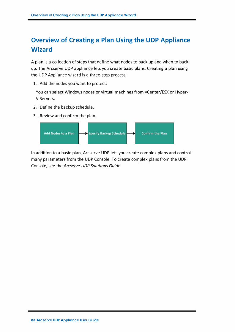
A plan is a collection of steps that define what nodes to back up and when to backup. The Arcserve UDP appliance lets you create basic plans. Creating a plan usingthe UDP Appliance wizard is a three-step process:
1. Add the nodes you want to protect.
You can select Windows nodes or virtual machines from vCenter/ESX or Hyper-V Servers.
2. Define the backup schedule.
3. Review and confirm the plan.
In addition to a basic plan, Arcserve UDP lets you create complex plans and controlmany parameters from the UDP Console. To create complex plans from the UDPConsole, see the Arcserve UDP Solutions Guide.
83 Arcserve UDP Appliance User Guide
How to Set up the Arcserve UDP Appliance and Create Plans
How to Set up the Arcserve UDP Appliance andCreate Plans
After the appliance restarts with the new hostname, the Unified Data Protectionwizard opens. The wizard lets you create a basic plan to schedule backups. The planlets you define the nodes you want to protect and when to create backups. Thebackup destination is the appliance Server.
Note: All the steps on the wizard are optional, you can skip these and directly openthe UDP console and create plans.
How to Run the Arcserve UDP Appliance Wizard
Follow these steps:
1. Log into the Arcserve UDP console.
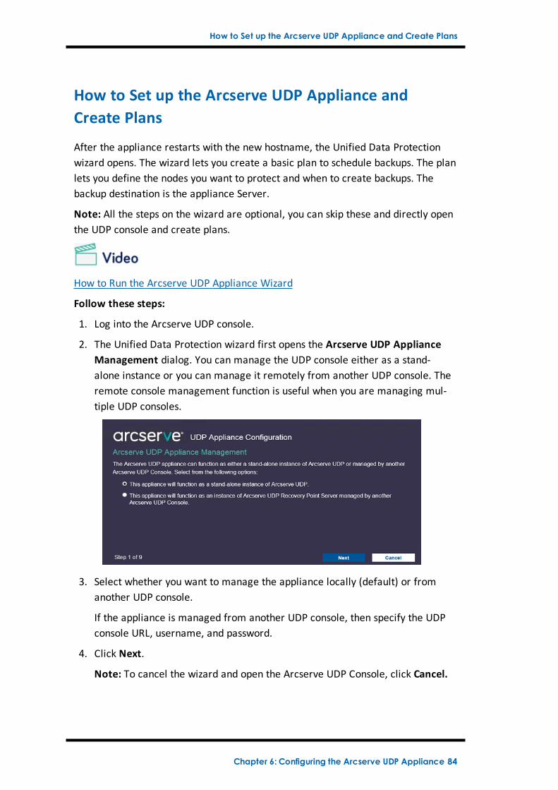
2. The Unified Data Protection wizard first opens the Arcserve UDP ApplianceManagement dialog. You can manage the UDP console either as a stand-alone instance or you can manage it remotely from another UDP console. Theremote console management function is useful when you are managing mul-tiple UDP consoles.
3. Select whether you want to manage the appliance locally (default) or fromanother UDP console.
If the appliance is managed from another UDP console, then specify the UDPconsole URL, username, and password.
4. Click Next.
Note: To cancel the wizard and open the Arcserve UDP Console, click Cancel.
Chapter 6: Configuring the Arcserve UDP Appliance 84
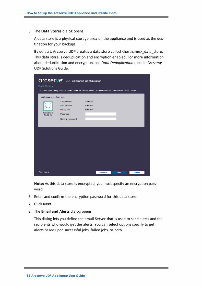
How to Set up the Arcserve UDP Appliance and Create Plans
5. The Data Stores dialog opens.
A data store is a physical storage area on the appliance and is used as the des-tination for your backups.
By default, Arcserve UDP creates a data store called <hostname>_data_store.This data store is deduplication and encryption enabled. For more informationabout deduplication and encryption, see Data Deduplication topic in ArcserveUDP Solutions Guide.
Note: As this data store is encrypted, you must specify an encryption pass-word.
6. Enter and confirm the encryption password for this data store.
7. Click Next.
8. The Email and Alerts dialog opens.
This dialog lets you define the email Server that is used to send alerts and therecipients who would get the alerts. You can select options specify to getalerts based upon successful jobs, failed jobs, or both.
85 Arcserve UDP Appliance User Guide
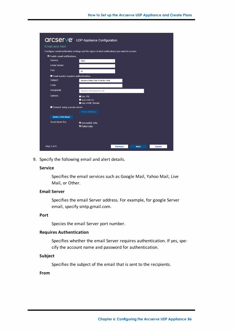
How to Set up the Arcserve UDP Appliance and Create Plans
9. Specify the following email and alert details.
Service
Specifies the email services such as Google Mail, Yahoo Mail, LiveMail, or Other.
Email Server
Specifies the email Server address. For example, for google Serveremail, specify smtp.gmail.com.
Port
Species the email Server port number.
Requires Authentication
Specifies whether the email Server requires authentication. If yes, spe-cify the account name and password for authentication.
Subject
Specifies the subject of the email that is sent to the recipients.
From
Chapter 6: Configuring the Arcserve UDP Appliance 86
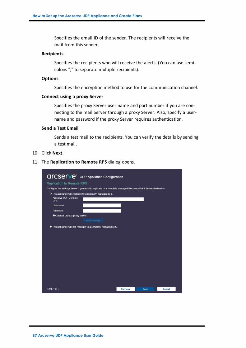
How to Set up the Arcserve UDP Appliance and Create Plans
Specifies the email ID of the sender. The recipients will receive themail from this sender.
Recipients
Specifies the recipients who will receive the alerts. (You can use semi-colons ";" to separate multiple recipients).
Options
Specifies the encryption method to use for the communication channel.
Connect using a proxy Server
Specifies the proxy Server user name and port number if you are con-necting to the mail Server through a proxy Server. Also, specify a user-name and password if the proxy Server requires authentication.
Send a Test Email
Sends a test mail to the recipients. You can verify the details by sendinga test mail.
10. Click Next.
11. The Replication to Remote RPS dialog opens.
87 Arcserve UDP Appliance User Guide
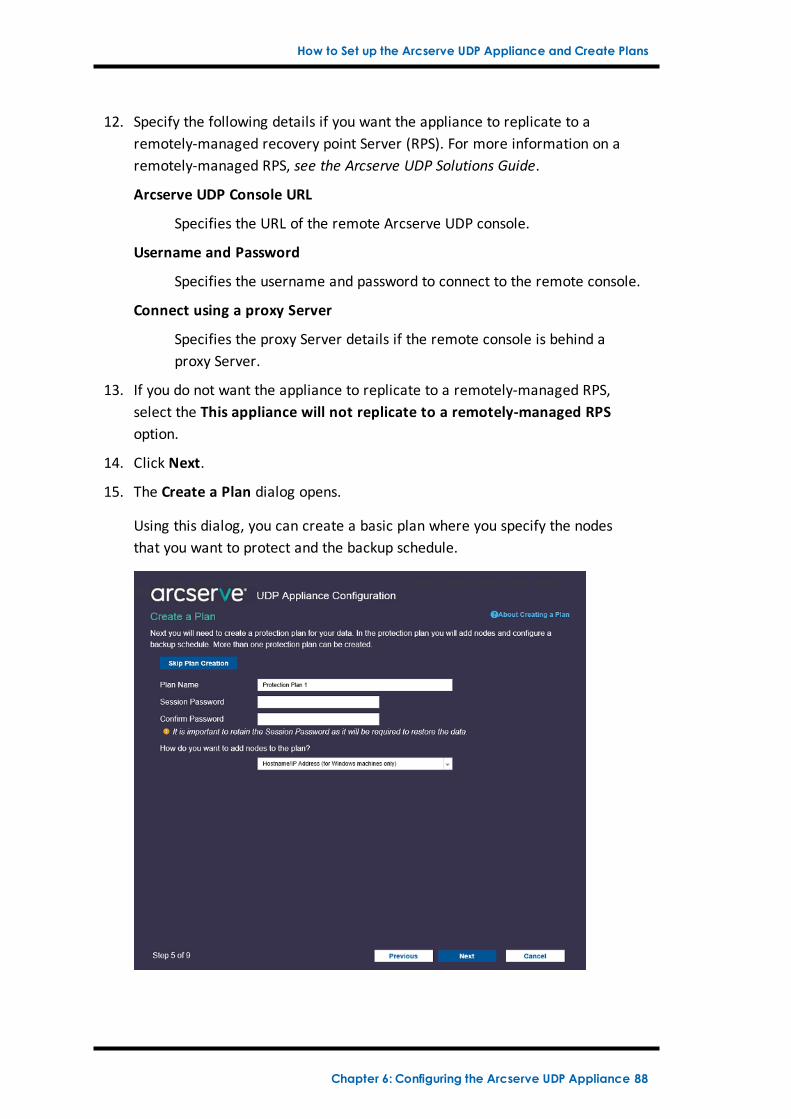
How to Set up the Arcserve UDP Appliance and Create Plans
12. Specify the following details if you want the appliance to replicate to aremotely-managed recovery point Server (RPS). For more information on aremotely-managed RPS, see the Arcserve UDP Solutions Guide.
Arcserve UDP Console URL
Specifies the URL of the remote Arcserve UDP console.
Username and Password
Specifies the username and password to connect to the remote console.
Connect using a proxy Server
Specifies the proxy Server details if the remote console is behind aproxy Server.
13. If you do not want the appliance to replicate to a remotely-managed RPS,select the This appliance will not replicate to a remotely-managed RPSoption.
14. Click Next.
15. The Create a Plan dialog opens.
Using this dialog, you can create a basic plan where you specify the nodesthat you want to protect and the backup schedule.
Chapter 6: Configuring the Arcserve UDP Appliance 88
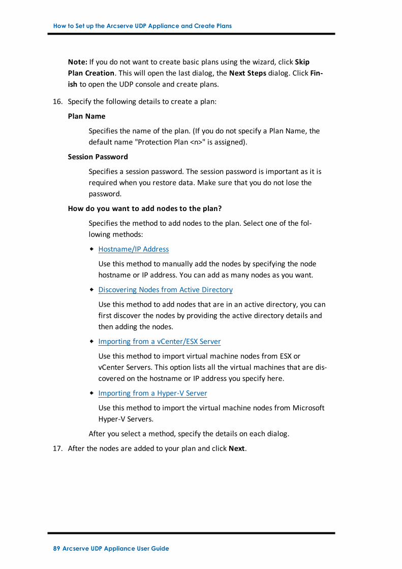
How to Set up the Arcserve UDP Appliance and Create Plans
Note: If you do not want to create basic plans using the wizard, click SkipPlan Creation. This will open the last dialog, the Next Steps dialog. Click Fin-ish to open the UDP console and create plans.
16. Specify the following details to create a plan:
Plan Name
Specifies the name of the plan. (If you do not specify a Plan Name, thedefault name "Protection Plan <n>" is assigned).
Session Password
Specifies a session password. The session password is important as it isrequired when you restore data. Make sure that you do not lose thepassword.
How do you want to add nodes to the plan?
Specifies the method to add nodes to the plan. Select one of the fol-lowing methods:
Hostname/IP Address
Use this method to manually add the nodes by specifying the nodehostname or IP address. You can add as many nodes as you want.
Discovering Nodes from Active Directory
Use this method to add nodes that are in an active directory, you canfirst discover the nodes by providing the active directory details andthen adding the nodes.
Importing from a vCenter/ESX Server
Use this method to import virtual machine nodes from ESX orvCenter Servers. This option lists all the virtual machines that are dis-covered on the hostname or IP address you specify here.
Importing from a Hyper-V Server
Use this method to import the virtual machine nodes from MicrosoftHyper-V Servers.
After you select a method, specify the details on each dialog.
17. After the nodes are added to your plan and click Next.
89 Arcserve UDP Appliance User Guide
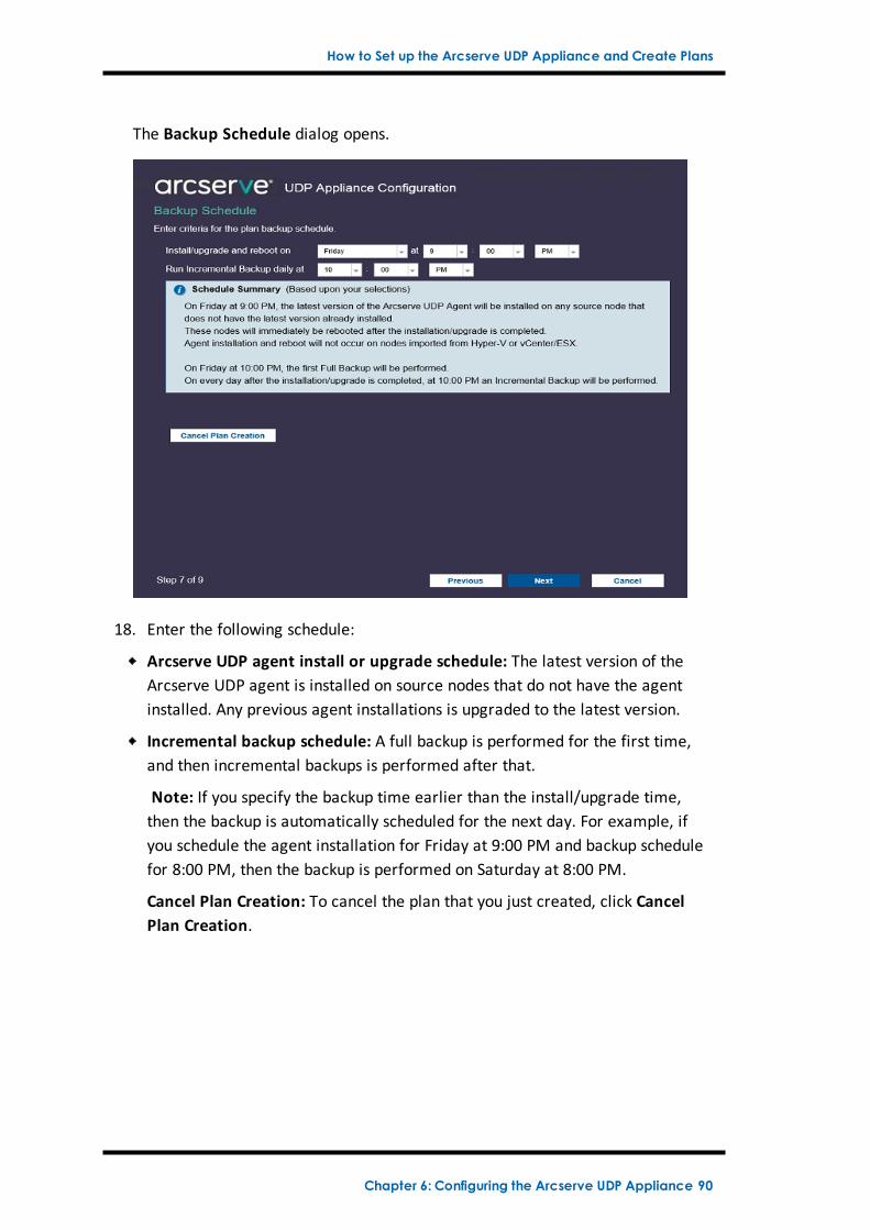
How to Set up the Arcserve UDP Appliance and Create Plans
The Backup Schedule dialog opens.
18. Enter the following schedule:
Arcserve UDP agent install or upgrade schedule: The latest version of theArcserve UDP agent is installed on source nodes that do not have the agentinstalled. Any previous agent installations is upgraded to the latest version.
Incremental backup schedule: A full backup is performed for the first time,and then incremental backups is performed after that.
Note: If you specify the backup time earlier than the install/upgrade time,then the backup is automatically scheduled for the next day. For example, ifyou schedule the agent installation for Friday at 9:00 PM and backup schedulefor 8:00 PM, then the backup is performed on Saturday at 8:00 PM.
Cancel Plan Creation: To cancel the plan that you just created, click CancelPlan Creation.
Chapter 6: Configuring the Arcserve UDP Appliance 90
How to Set up the Arcserve UDP Appliance and Create Plans
19. Click Next.
The Plan Confirmation dialog opens.
20. From here you can review the details of your plan. If necessary, you can editthe nodes or the schedule by clicking Edit Nodes or Edit Schedule, or you canadd or delete a plan.
Edit Nodes
Modifies the source nodes you want to protect.
Edit Schedule
Modifies the backup schedule.
21. After you are satisfied that the plans are correct, click Next.
The Next Steps dialog opens.
You have successfully completed the configuration and you are now ready towork in the Arcserve UDP Console. You can add more nodes to protect, cus-tomize plans with features such as virtual standby, and add more destinationsby including Recovery Point Servers and Data Stores.
91 Arcserve UDP Appliance User Guide
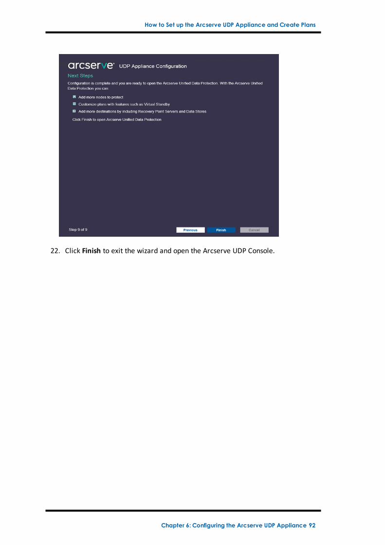
How to Set up the Arcserve UDP Appliance and Create Plans
22. Click Finish to exit the wizard and open the Arcserve UDP Console.
Chapter 6: Configuring the Arcserve UDP Appliance 92
Additional Information on Adding Nodes to a Plan
Additional Information on Adding Nodes to a Plan
You can create a plan to protect various nodes. To protect nodes, you need to addnodes to a plan. You can add nodes from the UDP Appliance wizard. The wizard letsyou add nodes using the following methods:
Manually entering the node IP Address or hostname
(Add Nodes by Hostname/IP Address)
Discovering nodes from an active directory
(Add Nodes by Active Directory)
Importing virtual machine nodes from VMware ESX/vCenter Servers
(Add vCenter/ESX Nodes)
Importing virtual machine nodes from Microsoft Hyper-V Servers
(Add Hyper-V Nodes)
93 Arcserve UDP Appliance User Guide
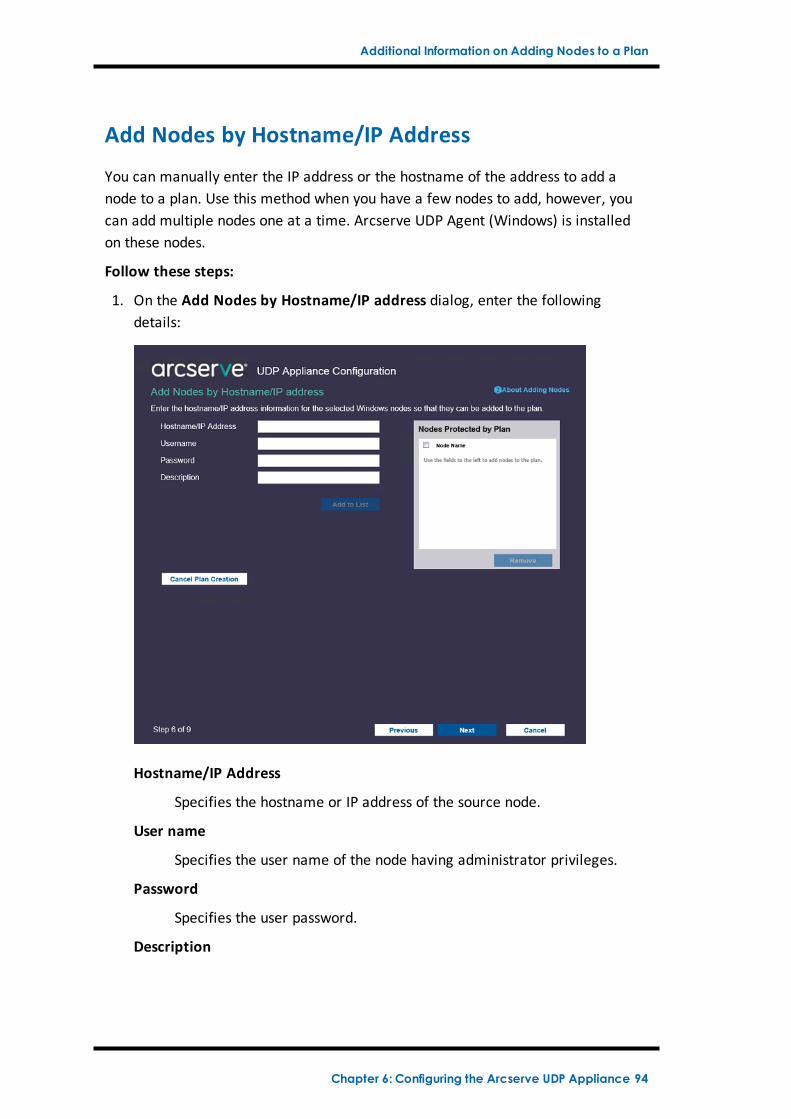
Additional Information on Adding Nodes to a Plan
Add Nodes by Hostname/IP Address
You can manually enter the IP address or the hostname of the address to add anode to a plan. Use this method when you have a few nodes to add, however, youcan add multiple nodes one at a time. Arcserve UDP Agent (Windows) is installedon these nodes.
Follow these steps:
1. On the Add Nodes by Hostname/IP address dialog, enter the followingdetails:
Hostname/IP Address
Specifies the hostname or IP address of the source node.
User name
Specifies the user name of the node having administrator privileges.
Password
Specifies the user password.
Description
Chapter 6: Configuring the Arcserve UDP Appliance 94
Additional Information on Adding Nodes to a Plan
Specifies any description to identify the node.
Cancel Plan Creation
Cancels the plan that you just created.
2. Click Add to List.
The node is added to the right pane. To add more nodes, repeat the steps. Allthe added nodes are listed on the right pane.
3. (Optional) To remove the added nodes from the list on the right pane, selectthe nodes and click Remove.
4. Click Next.
The nodes are added to the plan.
95 Arcserve UDP Appliance User Guide
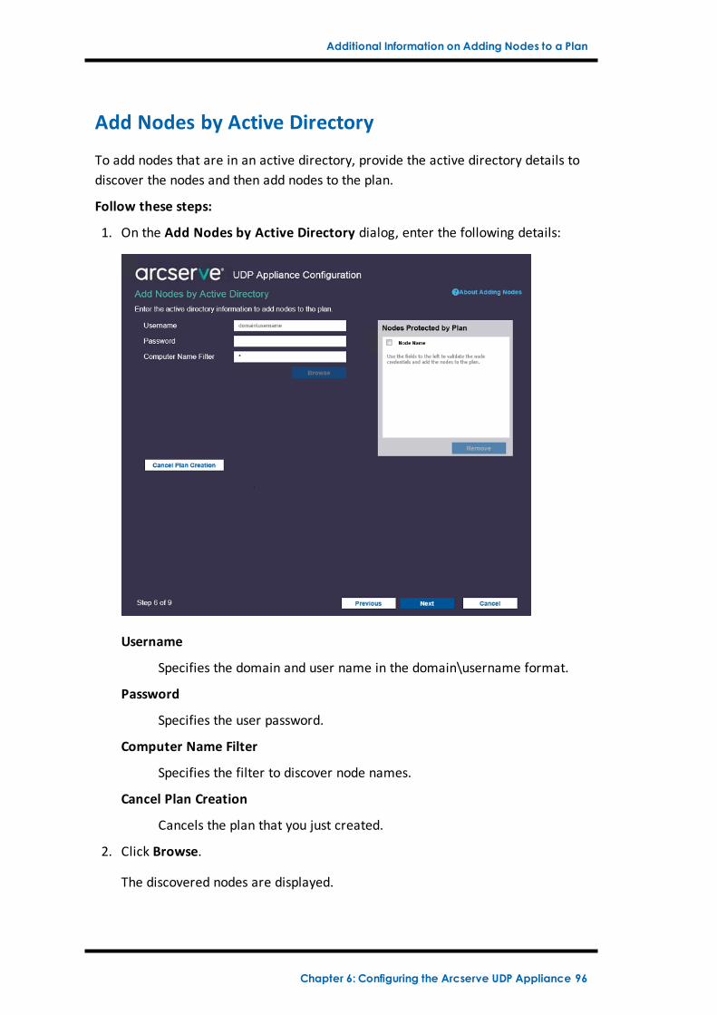
Additional Information on Adding Nodes to a Plan
Add Nodes by Active Directory
To add nodes that are in an active directory, provide the active directory details todiscover the nodes and then add nodes to the plan.
Follow these steps:
1. On the Add Nodes by Active Directory dialog, enter the following details:
Username
Specifies the domain and user name in the domain\username format.
Password
Specifies the user password.
Computer Name Filter
Specifies the filter to discover node names.
Cancel Plan Creation
Cancels the plan that you just created.
2. Click Browse.
The discovered nodes are displayed.
Chapter 6: Configuring the Arcserve UDP Appliance 96
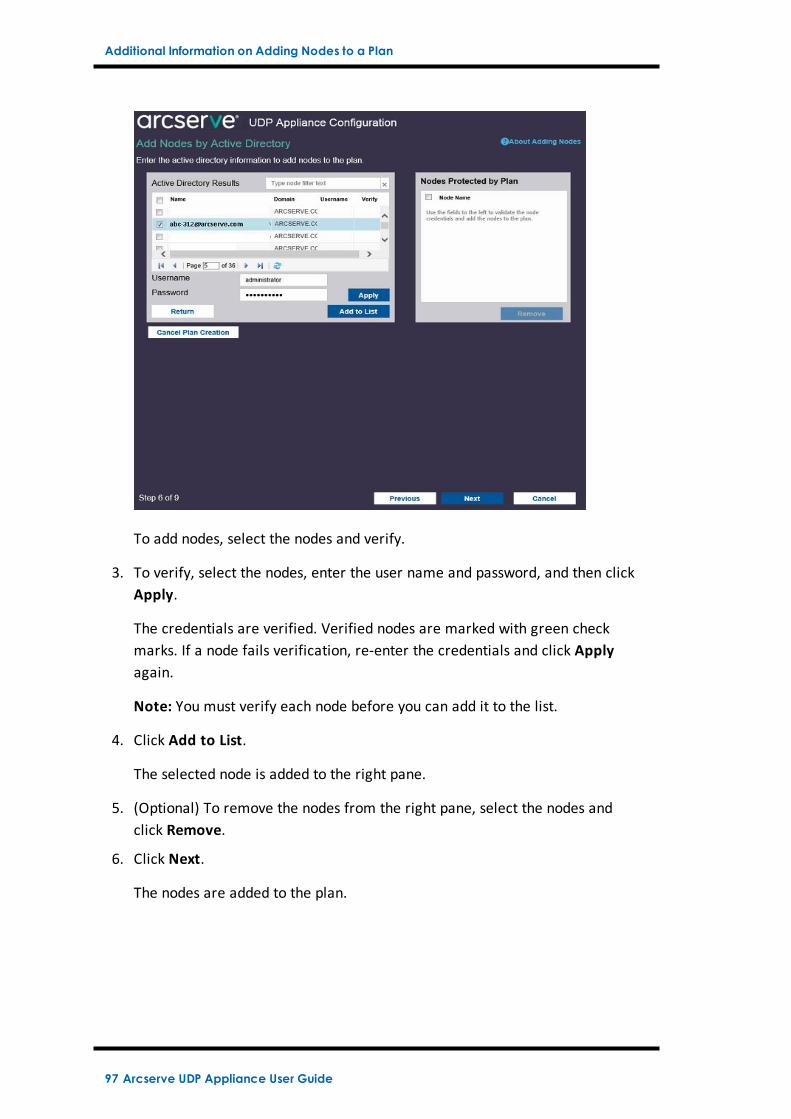
Additional Information on Adding Nodes to a Plan
To add nodes, select the nodes and verify.
3. To verify, select the nodes, enter the user name and password, and then clickApply.
The credentials are verified. Verified nodes are marked with green checkmarks. If a node fails verification, re-enter the credentials and click Applyagain.
Note: You must verify each node before you can add it to the list.
4. Click Add to List.
The selected node is added to the right pane.
5. (Optional) To remove the nodes from the right pane, select the nodes andclick Remove.
6. Click Next.
The nodes are added to the plan.
97 Arcserve UDP Appliance User Guide
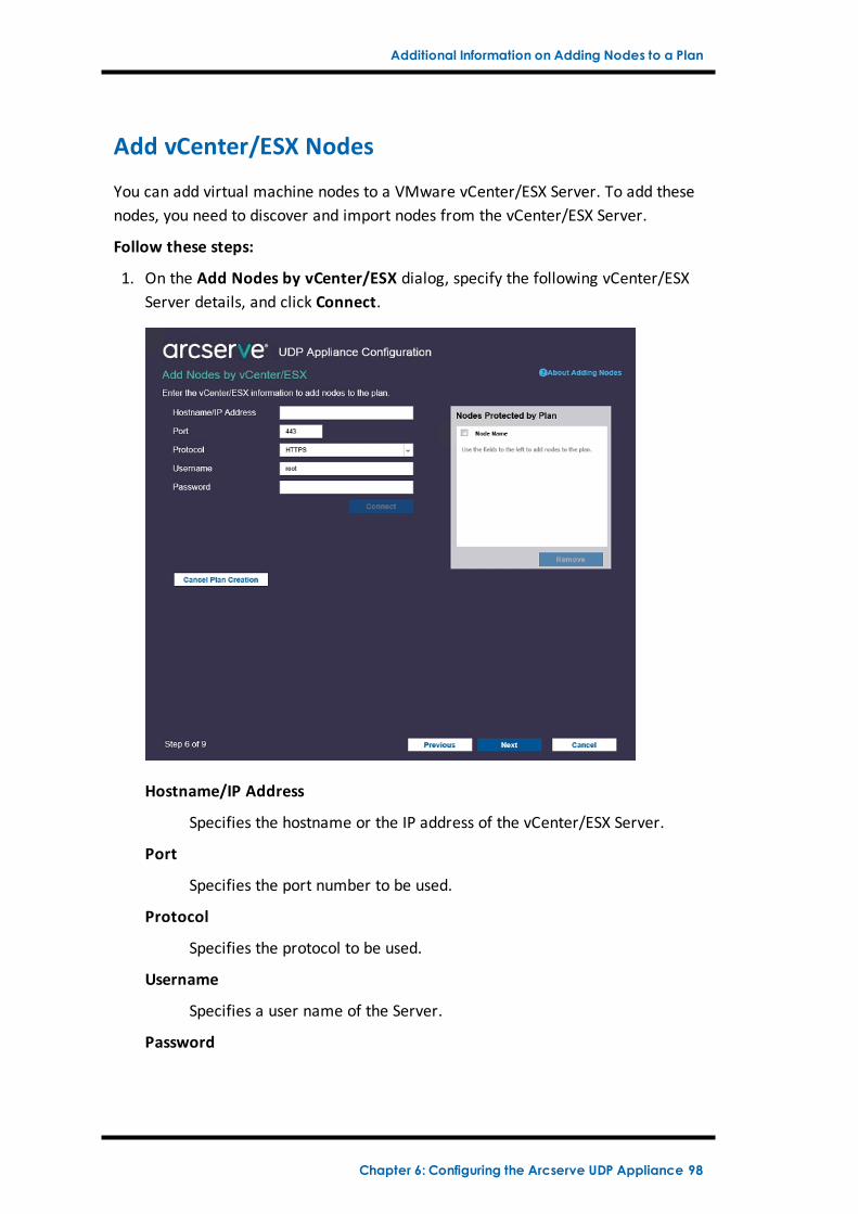
Additional Information on Adding Nodes to a Plan
Add vCenter/ESX Nodes
You can add virtual machine nodes to a VMware vCenter/ESX Server. To add thesenodes, you need to discover and import nodes from the vCenter/ESX Server.
Follow these steps:
1. On the Add Nodes by vCenter/ESX dialog, specify the following vCenter/ESXServer details, and click Connect.
Hostname/IP Address
Specifies the hostname or the IP address of the vCenter/ESX Server.
Port
Specifies the port number to be used.
Protocol
Specifies the protocol to be used.
Username
Specifies a user name of the Server.
Password
Chapter 6: Configuring the Arcserve UDP Appliance 98
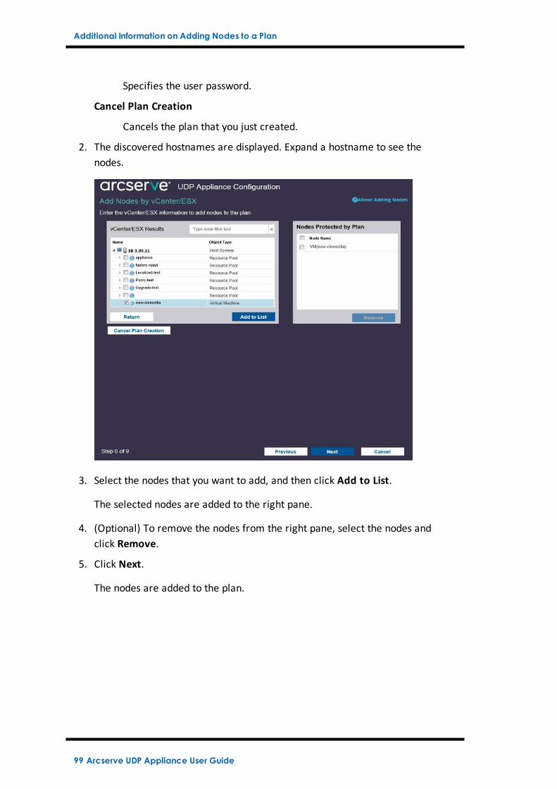
Additional Information on Adding Nodes to a Plan
Specifies the user password.
Cancel Plan Creation
Cancels the plan that you just created.
2. The discovered hostnames are displayed. Expand a hostname to see thenodes.
3. Select the nodes that you want to add, and then click Add to List.
The selected nodes are added to the right pane.
4. (Optional) To remove the nodes from the right pane, select the nodes andclick Remove.
5. Click Next.
The nodes are added to the plan.
99 Arcserve UDP Appliance User Guide
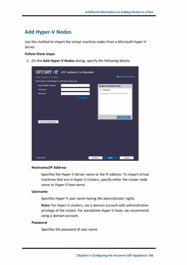
Additional Information on Adding Nodes to a Plan
Add Hyper-V Nodes
Use this method to import the virtual machine nodes from a Microsoft Hyper-VServer.
Follow these steps:
1. On the Add Hyper-V Nodes dialog, specify the following details.
Hostname/IP Address
Specifies the Hyper-V Server name or the IP address. To import virtualmachines that are in Hyper-V clusters, specify either the cluster nodename or Hyper-V host name.
Username
Specifies Hyper-V user name having the administrator rights.
Note: For Hyper-V clusters, use a domain account with administrativeprivilege of the cluster. For standalone Hyper-V hosts, we recommendusing a domain account.
Password
Specifies the password of user name.
Chapter 6: Configuring the Arcserve UDP Appliance 100
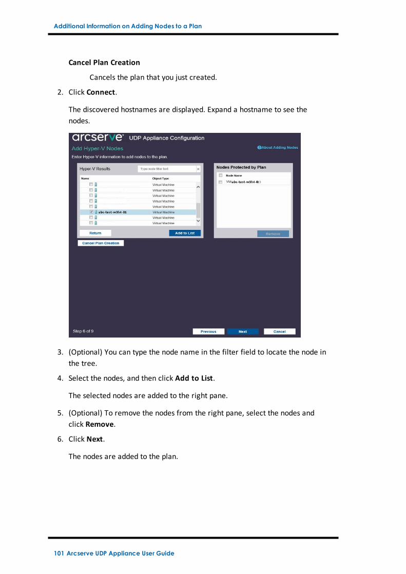
Additional Information on Adding Nodes to a Plan
Cancel Plan Creation
Cancels the plan that you just created.
2. Click Connect.
The discovered hostnames are displayed. Expand a hostname to see thenodes.
3. (Optional) You can type the node name in the filter field to locate the node inthe tree.
4. Select the nodes, and then click Add to List.
The selected nodes are added to the right pane.
5. (Optional) To remove the nodes from the right pane, select the nodes andclick Remove.
6. Click Next.
The nodes are added to the plan.
101 Arcserve UDP Appliance User Guide
Configure UDP Appliance as Gateway
Configure UDP Appliance as Gateway
You can configure the Arcserve UDP Appliance as Gateway.
Follow these steps:
1. Uninstall Arcserve UDP Console from the Arcserve UDP Appliance.
2. From the Arcserve UDP Console, click the resources tab.
3. From the left pane of the Arcserve UDP Console, navigate to Infrastructures,and click Sites.
4. Click Add a Site.
5. Follow the instructions provided in the Add a Site wizard to install ArcserveUDP Remote Management Gateway on the Arcserve UDP Appliance.
Note: After installing Arcserve UDP Remote Management Gateway on theArcserve UDP Appliance, click Launch Wizard on the Arcserve UDP Appliancewizard does not launch the Arcserve UDP Console. To access the ArcserveUDP Console, provide the URL of Arcserve UDP Console directly.
Chapter 6: Configuring the Arcserve UDP Appliance 102
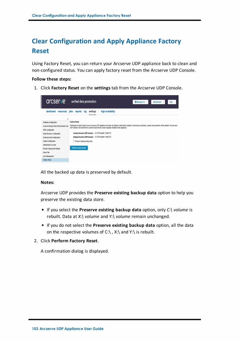
Clear Configuration and Apply Appliance Factory Reset
Clear Configuration and Apply Appliance FactoryReset
Using Factory Reset, you can return your Arcserve UDP appliance back to clean andnon-configured status. You can apply factory reset from the Arcserve UDP Console.
Follow these steps:
1. Click Factory Reset on the settings tab from the Arcserve UDP Console.
All the backed up data is preserved by default.
Notes:
Arcserve UDP provides the Preserve existing backup data option to help youpreserve the existing data store.
If you select the Preserve existing backup data option, only C:\ volume isrebuilt. Data at X:\ volume and Y:\ volume remain unchanged.
If you do not select the Preserve existing backup data option, all the dataon the respective volumes of C:\ , X:\ and Y:\ is rebuilt.
2. Click Perform Factory Reset.
A confirmation dialog is displayed.
103 Arcserve UDP Appliance User Guide
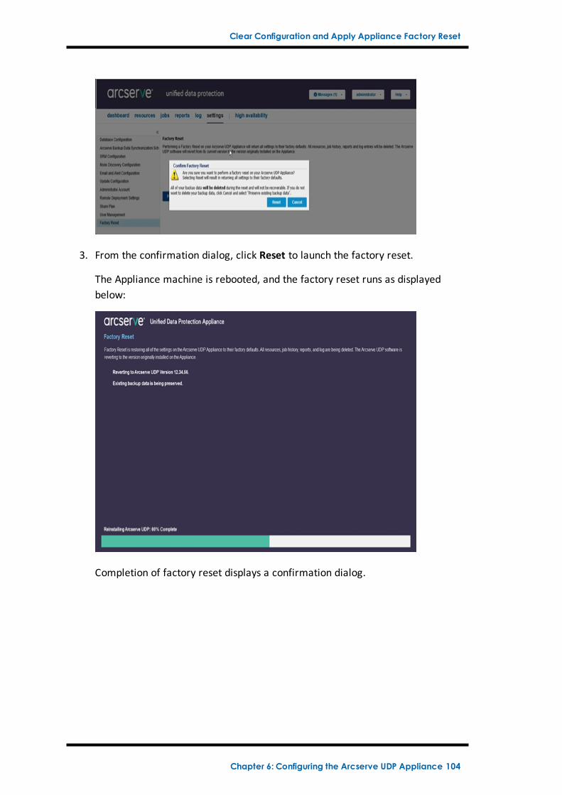
Clear Configuration and Apply Appliance Factory Reset
3. From the confirmation dialog, click Reset to launch the factory reset.
The Appliance machine is rebooted, and the factory reset runs as displayedbelow:
Completion of factory reset displays a confirmation dialog.
Chapter 6: Configuring the Arcserve UDP Appliance 104
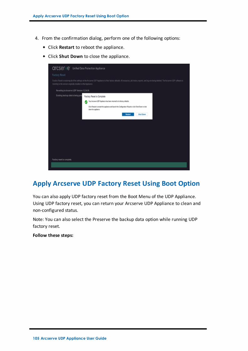
Apply Arcserve UDP Factory Reset Using Boot Option
4. From the confirmation dialog, perform one of the following options:
Click Restart to reboot the appliance.
Click Shut Down to close the appliance.
Apply Arcserve UDP Factory Reset Using Boot Option
You can also apply UDP factory reset from the Boot Menu of the UDP Appliance.Using UDP factory reset, you can return your Arcserve UDP Appliance to clean andnon-configured status.
Note: You can also select the Preserve the backup data option while running UDPfactory reset.
Follow these steps:
105 Arcserve UDP Appliance User Guide
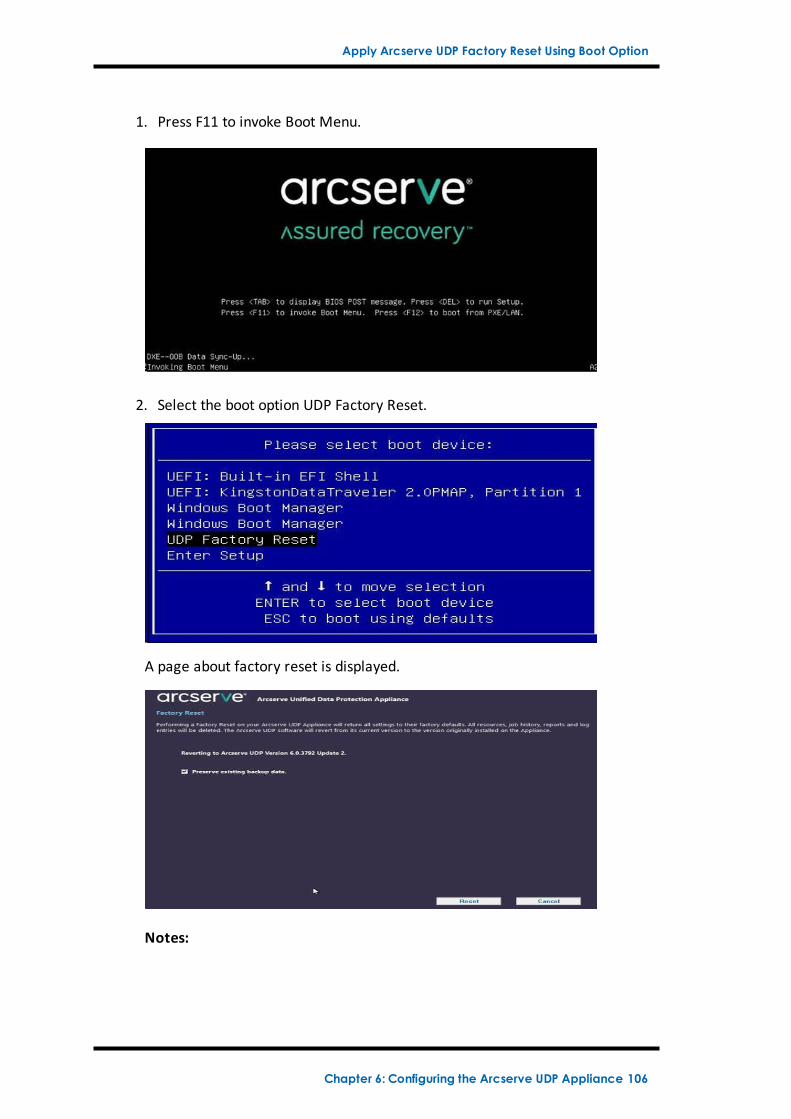
Apply Arcserve UDP Factory Reset Using Boot Option
1. Press F11 to invoke Boot Menu.
2. Select the boot option UDP Factory Reset.
A page about factory reset is displayed.
Notes:
Chapter 6: Configuring the Arcserve UDP Appliance 106
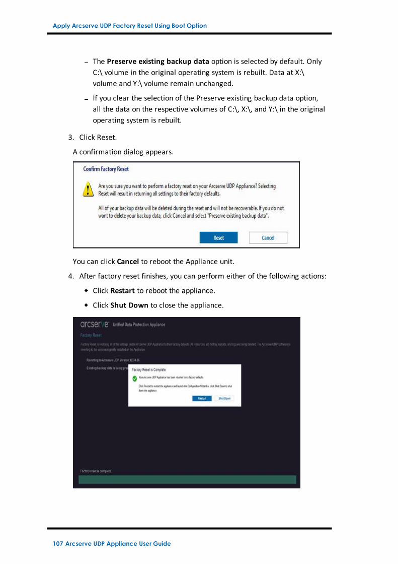
Apply Arcserve UDP Factory Reset Using Boot Option
The Preserve existing backup data option is selected by default. OnlyC:\ volume in the original operating system is rebuilt. Data at X:\volume and Y:\ volume remain unchanged.
If you clear the selection of the Preserve existing backup data option,all the data on the respective volumes of C:\, X:\, and Y:\ in the originaloperating system is rebuilt.
3. Click Reset.
A confirmation dialog appears.
You can click Cancel to reboot the Appliance unit.
4. After factory reset finishes, you can perform either of the following actions:
Click Restart to reboot the appliance.
Click Shut Down to close the appliance.
107 Arcserve UDP Appliance User Guide
How to Activate Arcserve Product on the Appliance
How to Activate Arcserve Product on the Appliance
For activating Arcserve product on the Appliance, refer to Activating ArcserveProduct License Online topic in Solutions Guide.
Chapter 6: Configuring the Arcserve UDP Appliance 108
Chapter 7: Creating Backup PlansUsing UDP Appliance, you can create backup plans for Windows, Linux, and virtualmachines. You can also write data to a tape device and create a virtual standbymachine.
This section contains the following topics:
Create a Backup Plan for Linux Nodes 110
Create a Backup Plan to a Tape Device 111
Create an On-Appliance Virtual Standby Plan 112
Chapter 7: Creating Backup Plans 109
Create a Backup Plan for Linux Nodes
Create a Backup Plan for Linux Nodes
You can back up Linux nodes from the Appliance Console. The Linux Backup Serveris already added to the Console.
Follow these steps:
1. Open the Appliance Console.
2. Click resources, Plans, All Plans.
3. Create a Linux Backup plan.
4. Specify the Source, Destination, Schedule, and Advanced configurations.
Note: For more information about each of the configurations, see How toCreate a Linux Backup Plan in the Solutions Guide.
5. Run the backup plan.
110 Arcserve UDP Appliance User Guide
Create a Backup Plan to a Tape Device
Create a Backup Plan to a Tape Device
UDP Appliance has the capability to write data to a tape device. Typically, thesource data is the recovery point that you have saved in a data store using the UDPbackup plan, and the destination is a tape device. You need to use Arcserve BackupManager to manage your backup jobs to a tape.
The following process overview gives you an idea on how to write to a tape deviceusing the UDP Appliance:
1. Attach the tape device to the UDP Appliance
UDP Appliance comes with a port at the rear panel to attach your tapedevice. Once you attach the tape device, UDP Appliance automatically iden-tifies the tape device.
2. Configure the tape device using the Backup Manager
Open the Backup Manager and add the tape device to Backup Manager.Backup Manager is the interface that lets you manage Arcserve Backup. Afteryou add the tape device to Backup Manager, configure the device.
Note: For more information on configuring and managing the device, seeManaging Devices and Media in Arcserve Backup for Windows AdministrationGuide.
3. Successfully complete at least one backup job using the UDP Console
You need at least one successful backup that you can write to a tape device.To back up data, create a plan using the UDP Console and back up to a datastore.
Note: For more information about creating a backup plan for different nodes,see Creating Plans to Protect data in the Solutions Guide.
4. Initiate a backup to tape job from Backup Manager
Open the Backup Manager and create a plan to back up data to the tapedevice. Here the source data is the destination of UDP backup plan and thedestination is the tape device.
Note: For more information on creating a backup plan to tape, see BackingUp and Recovering D2D/UDP Data in Arcserve Backup for Windows Admin-istration Guide.
Chapter 7: Creating Backup Plans 111
Create an On-Appliance Virtual Standby Plan
Create an On-Appliance Virtual Standby Plan
Appliance has the capability to serve as a virtual standby machine. This capability ispresent in the following Appliance series:
Arcserve UDP Appliance 7200V
Arcserve UDP Appliance 7300V
Arcserve UDP Appliance 7400V
Arcserve UDP Appliance 7500V
Arcserve UDP Appliance 7600V
Arcserve UDP Appliance 8100
Arcserve UDP Appliance 8200
Arcserve UDP Appliance 8300
Arcserve UDP Appliance 8400
Prerequisite: You must have a successful backup plan.
Follow these steps:
1. Open the Appliance Console.
2. Navigate to the plans and modify the backup plan.
3. Add a Virtual Standby task.
4. Update the Source, Destination, Virtual Machine configurations.
Note: For more information about the configurations, see How to Create a Vir-tual Standby Plan topic in the Solutions Guide.
5. Save and run the plan.
112 Arcserve UDP Appliance User Guide
Chapter 8: Repairing the Arcserve UDP ApplianceThis section contains the following topics:
Remove and Replace a Hard Drive 114
Chapter 8: Repairing the Arcserve UDP Appliance 113
Remove and Replace a Hard Drive
Remove and Replace a Hard Drive
With the Arcserve UDP appliance, if one hard drive fails, the rest of the drives willkick in immediately to ensure no data is lost and the appliance continues to worknormally. Therefore, to guard against any problems associated with multiple harddrive failures, it is important to replace a hard drive as soon as possible to min-imize potential loss of data.
The Arcserve UDP appliance contains four hard drive carriers which are labeled 0,1, 2 and 3 from left to right. If you replace more than one hard drive at a time, youshould label the replacement hard drives so that you know which drive is placedinto each drive carrier. You should also label the hard drives that you remove fromthe appliance so that you know which drive carrier they occupied.
Important! Take proper safety precautions when handling the hard drives becausethey are static-sensitive devices and can be easily damaged.
Wear a wrist strap to prevent any static discharge.
Touch a grounded object before removing the replacement hard disk from theantistatic shipping bag.
Always handle a hard drive by the edges only and do not touch any of the vis-ible components on the bottom.
Follow these steps:
1. To gain access to the drive holders, you first need to remove the faceplate:
a. Unlock the faceplate lock.
b. Press the release knob to retract the faceplate pins.
c. Carefully remove the faceplate (using two hands).
2. Press the release latch on the drive carrier. This extends the drive carrierhandle.
114 Arcserve UDP Appliance User Guide
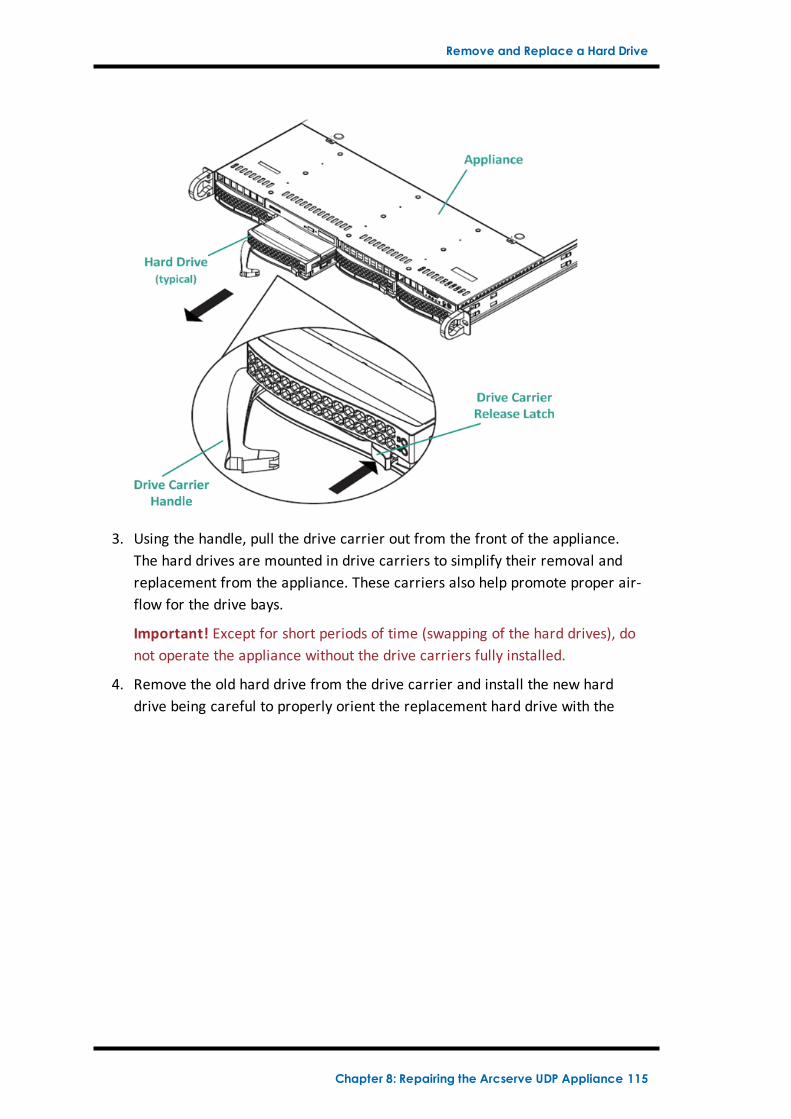
Remove and Replace a Hard Drive
3. Using the handle, pull the drive carrier out from the front of the appliance.The hard drives are mounted in drive carriers to simplify their removal andreplacement from the appliance. These carriers also help promote proper air-flow for the drive bays.
Important! Except for short periods of time (swapping of the hard drives), donot operate the appliance without the drive carriers fully installed.
4. Remove the old hard drive from the drive carrier and install the new harddrive being careful to properly orient the replacement hard drive with the
Chapter 8: Repairing the Arcserve UDP Appliance 115
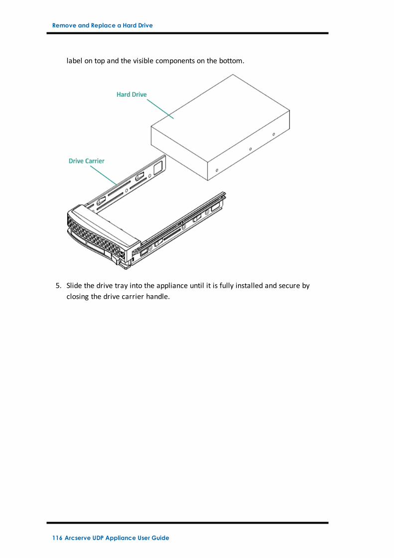
Remove and Replace a Hard Drive
label on top and the visible components on the bottom.
5. Slide the drive tray into the appliance until it is fully installed and secure byclosing the drive carrier handle.
116 Arcserve UDP Appliance User Guide
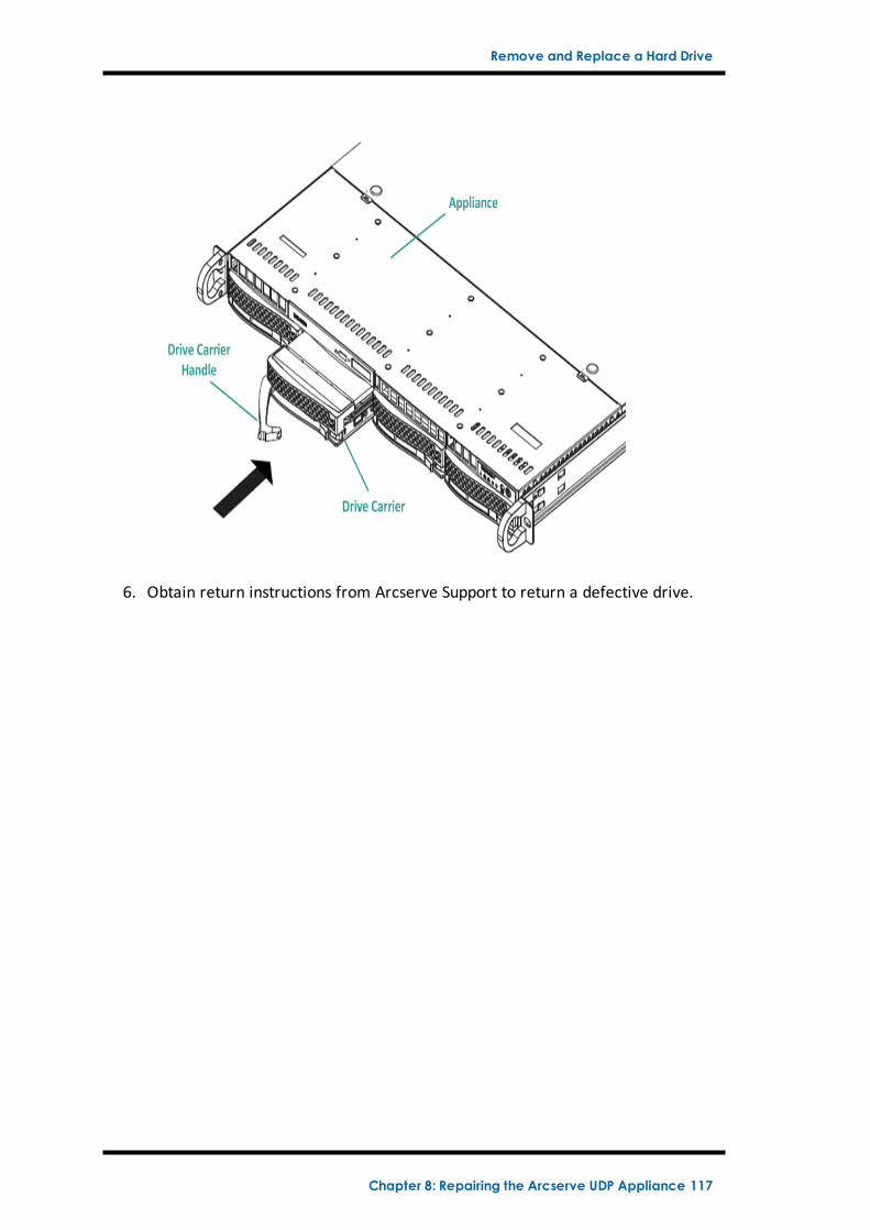
Remove and Replace a Hard Drive
6. Obtain return instructions from Arcserve Support to return a defective drive.
Chapter 8: Repairing the Arcserve UDP Appliance 117
Chapter 9: Safety PrecautionsThis section contains the following topics:
General Safety Precautions 119
Electrical Safety Precautions 121
FCC Compliance 122
Electrostatic Discharge (ESD) Precautions 123
Chapter 9: Safety Precautions 118
General Safety Precautions
General Safety Precautions
The following are general safety precautions you should adhere to in order to pro-tect yourself from harm and to protect the appliance from damage or malfunction:
For EMI Class A Equipment (Business equipment), this equipment is registeredfor Electromagnetic Conformity Registration as business equipment (A) and nothome equipment. Sellers or users are required to take caution in this regard.
A급기기 (업무용방송통신기자재 )
이기기는업무용 (A급 )으로전자파적합기기로서판매자또는사용자는이점을주의하시기바라며 ,가정외의지역에서사용하는것을목적으로합니다
Note: This safety precaution only applies to South Korea. For more details, con-tact Arcserve Support at https://www.arcserve.com/support or call0079885215375 (South Korea).
Inspect the box that the appliance was shipped in and ensure that there are novisible signs of damage. If there is evidence of damage, please retain all pack-aging materials and contact Arcserve Support immediately at: https://www.arc-serve.com/support.
Decide on a suitable location for the rack unit that will hold the appliance. Itshould be situated in a clean, dust-free area that is well ventilated and free ofclutter. Avoid areas where heat, electrical noise, and electromagnetic fieldsare generated.
You will also need it placed near at least one grounded power outlet. Depend-ing on the model, the appliance includes either one power supply or a redund-ant power supply and will then require two grounded outlets.
The appliance is only for use in a restricted location.
Access can only be gained by service persons or by users who have beeninstructed about the reasons for the restrictions applied to the locationand about any precautions that shall be taken; and
Access is through the use of a tool or lock and key, or other means ofsecurity, and is controlled by the authority responsible for the location.
Place the appliance top cover and any components that have been removedaway from the appliance or on a table so that they will not be accidentallystepped on.
119 Arcserve UDP Appliance User Guide
General Safety Precautions
While working on the appliance, do not wear loose clothing such as necktiesand unbuttoned shirt sleeves, which can come into contact with electrical cir-cuits or be pulled into a cooling fan.
Remove any jewelry or metal objects from your body, which are excellentmetal conductors that can create short circuits and harm you if they come intocontact with printed circuit boards (PCBs) or areas where power is present.
After accessing the inside of the appliance, close the appliance and secure it tothe rack unit with the retention screws after ensuring that all connections havebeen made.
Chapter 9: Safety Precautions 120
Electrical Safety Precautions
Electrical Safety Precautions
The following are electrical safety precautions you should adhere to in order to pro-tect yourself from harm and to protect the appliance from damage or malfunction:
Be aware of the locations of the power on/off switch on the appliance as wellas the room's emergency power-off switch, disconnection switch, or electricaloutlet. If an electrical accident occurs, you can then quickly remove powerfrom the appliance.
Do not work alone when working with high-voltage components.
Power should always be disconnected from the appliance when removing orinstalling main system components, such as the Serverboard, memory modulesand the DVD-ROM and floppy drives (not necessary for hot swappable drives).When disconnecting power, you should first power down the appliance with theoperating system and then unplug the power cords from all the power supplymodules in the appliance.
When working around exposed electrical circuits, another person who is famil-iar with the power-off controls should be nearby to switch off the power, ifnecessary.
Use only one hand when working with powered-on electrical equipment. This isto avoid making a complete circuit, which will cause electrical shock. Useextreme caution when using metal tools, which can easily damage any elec-trical components or circuit boards they come into contact with.
Do not use mats designed to decrease electrostatic discharge as protectionfrom electrical shock. Instead, use rubber mats that have been specificallydesigned as electrical insulators.
The power supply power cord must include a grounding plug and must beplugged into grounded electrical outlets.
Serverboard Battery: CAUTION - There is a danger of explosion if the onboardbattery is installed upside down, which will reverse its polarities This batterymust be replaced only with the same or an equivalent type recommended bythe manufacturer. Dispose of used batteries according to the manufacturer’sinstructions.
DVD-ROM laser: CAUTION - this Server may have come equipped with a DVD-ROM drive. To prevent direct exposure to the laser beam and hazardous radi-ation exposure, do not open the enclosure or use the unit in any unconventionalway.
121 Arcserve UDP Appliance User Guide
FCCCompliance
FCC Compliance
This appliance complies with part 15 of the FCC Rules. Operation is subject to thefollowing conditions:
This appliance may not cause harmful interference, and
This appliance must accept any interference received, including interferencethat may cause undesired operation
Note: This equipment has been tested and found to comply with the limits for aClass A digital device, pursuant to part 15 of the FCC Rules. These limits aredesigned to provide reasonable protection against harmful interference when theequipment is operated in a commercial environment. This equipment generates,uses, and can radiate radio frequency energy and, if not installed and used inaccordance with the instruction manual, may cause harmful interference to radiocommunications. Operation of this equipment in a residential area is likely to causeharmful interference in which case the user is required to correct the interferenceat his own expense.
Chapter 9: Safety Precautions 122
Electrostatic Discharge (ESD) Precautions
Electrostatic Discharge (ESD) Precautions
Electrostatic Discharge (ESD) is generated by two objects with different electricalcharges coming into contact with each other. An electrical discharge is created toneutralize this difference, which can damage electronic components and printed cir-cuit boards. Devices that are sensitive to ESD, such as Serverboards, motherboards,PCIe cards, drives, processors, and memory cards require special handling. Use thefollowing precautions to help neutralize the difference of electrical charges cominginto contact with each other, before contact is made, to protect your equipmentfrom ESD:
Use a rubber mat that has been specifically designed as an electrical insulator.Do not use a mat designed to decrease electrostatic discharge as protectionfrom electrical shock.
Use a grounded wrist strap designed to prevent static discharge.
Use antistatic or electrostatic discharge (ESD) preventive clothing or gloves.
Keep all components and printed circuit boards (PCBs) in their antistatic bagsuntil ready for use.
Touch a grounded metal object before removing the board from the antistaticbag.
Do not let components or PCBs come into contact with your clothing, whichmay retain a charge even if you are wearing a wrist strap.
Handle a board by its edges only. Do not touch its components, peripheralchips, memory modules, or contacts.
When handling chips or modules, avoid touching their pins.
Put the Serverboard and peripherals back into their antistatic bags when not inuse.
For grounding purposes, verify your appliance provides excellent conductivitybetween the power supply, the case, the mounting fasteners, and the Ser-verboard.
123 Arcserve UDP Appliance User Guide
Chapter 10: Changing the IPMI PasswordThis section contains the following topics:
How to Change the IPMI Password 125
Chapter 10: Changing the IPMI Password 124
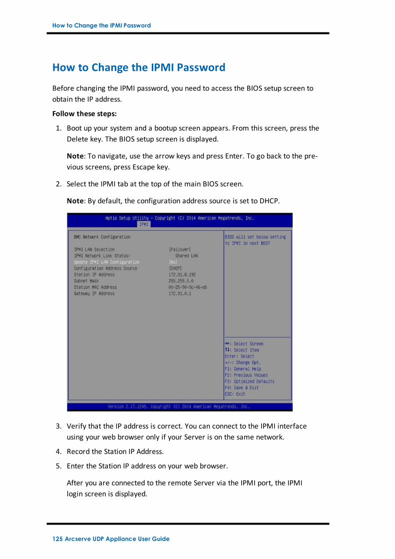
How to Change the IPMI Password
How to Change the IPMI Password
Before changing the IPMI password, you need to access the BIOS setup screen toobtain the IP address.
Follow these steps:
1. Boot up your system and a bootup screen appears. From this screen, press theDelete key. The BIOS setup screen is displayed.
Note: To navigate, use the arrow keys and press Enter. To go back to the pre-vious screens, press Escape key.
2. Select the IPMI tab at the top of the main BIOS screen.
Note: By default, the configuration address source is set to DHCP.
3. Verify that the IP address is correct. You can connect to the IPMI interfaceusing your web browser only if your Server is on the same network.
4. Record the Station IP Address.
5. Enter the Station IP address on your web browser.
After you are connected to the remote Server via the IPMI port, the IPMIlogin screen is displayed.
125 Arcserve UDP Appliance User Guide
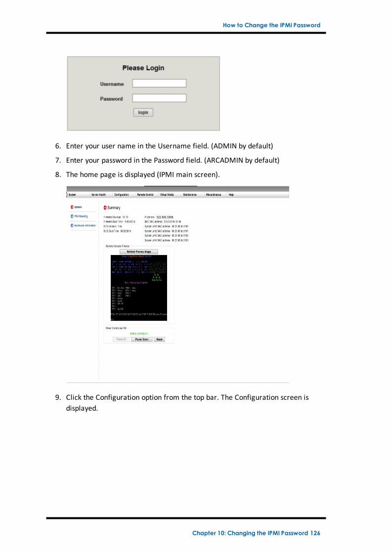
How to Change the IPMI Password
6. Enter your user name in the Username field. (ADMIN by default)
7. Enter your password in the Password field. (ARCADMIN by default)
8. The home page is displayed (IPMI main screen).
9. Click the Configuration option from the top bar. The Configuration screen isdisplayed.
Chapter 10: Changing the IPMI Password 126
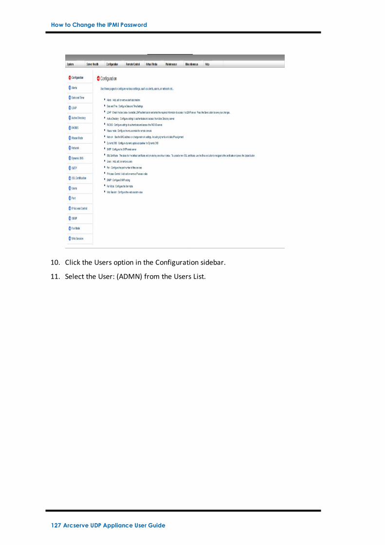
How to Change the IPMI Password
10. Click the Users option in the Configuration sidebar.
11. Select the User: (ADMN) from the Users List.
127 Arcserve UDP Appliance User Guide
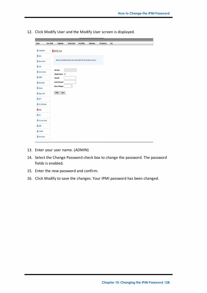
How to Change the IPMI Password
12. Click Modify User and the Modify User screen is displayed.
13. Enter your user name. (ADMIN)
14. Select the Change Password check box to change the password. The passwordfields is enabled.
15. Enter the new password and confirm.
16. Click Modify to save the changes. Your IPMI password has been changed.
Chapter 10: Changing the IPMI Password 128
Chapter 11: Connecting Appliance Expansion Shelf tothe Appliance ServerThis section contains the following topics:
Appliance Infield Expansion for all the AvailableModels 130
What is included in the box 140
How to Connect the Appliance Expansion Shelf to the Appliance Server 143
How to Modify Arcserve UDP Data store 152
Chapter 11: Connecting Appliance Expansion Shelf to the Appliance Server 129
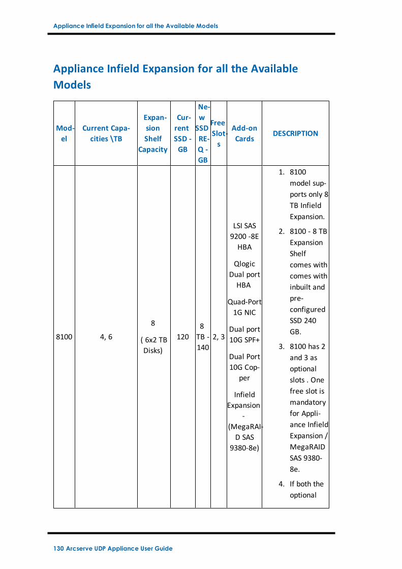
Appliance Infield Expansion for all the Available Models
Appliance Infield Expansion for all the AvailableModels
Mod-el
Current Capa-cities \TB
Expan-sionShelf
Capacity
Cur-rentSSD -GB
Ne-wSSDRE-Q -GB
FreeSlot-s
Add-onCards
DESCRIPTION
8100 4, 6
8
( 6x2 TBDisks)
1208TB -140
2, 3
LSI SAS9200 -8EHBA
QlogicDual portHBA
Quad-Port1G NIC
Dual port10G SPF+
Dual Port10G Cop-
per
InfieldExpansion
-(MegaRAI-D SAS
9380-8e)
1. 8100model sup-ports only 8TB InfieldExpansion.
2. 8100 - 8 TBExpansionShelfcomes withcomes withinbuilt andpre-configuredSSD 240GB.
3. 8100 has 2and 3 asoptionalslots . Onefree slot ismandatoryfor Appli-ance InfieldExpansion /MegaRAIDSAS 9380-8e.
4. If both theoptional
130 Arcserve UDP Appliance User Guide
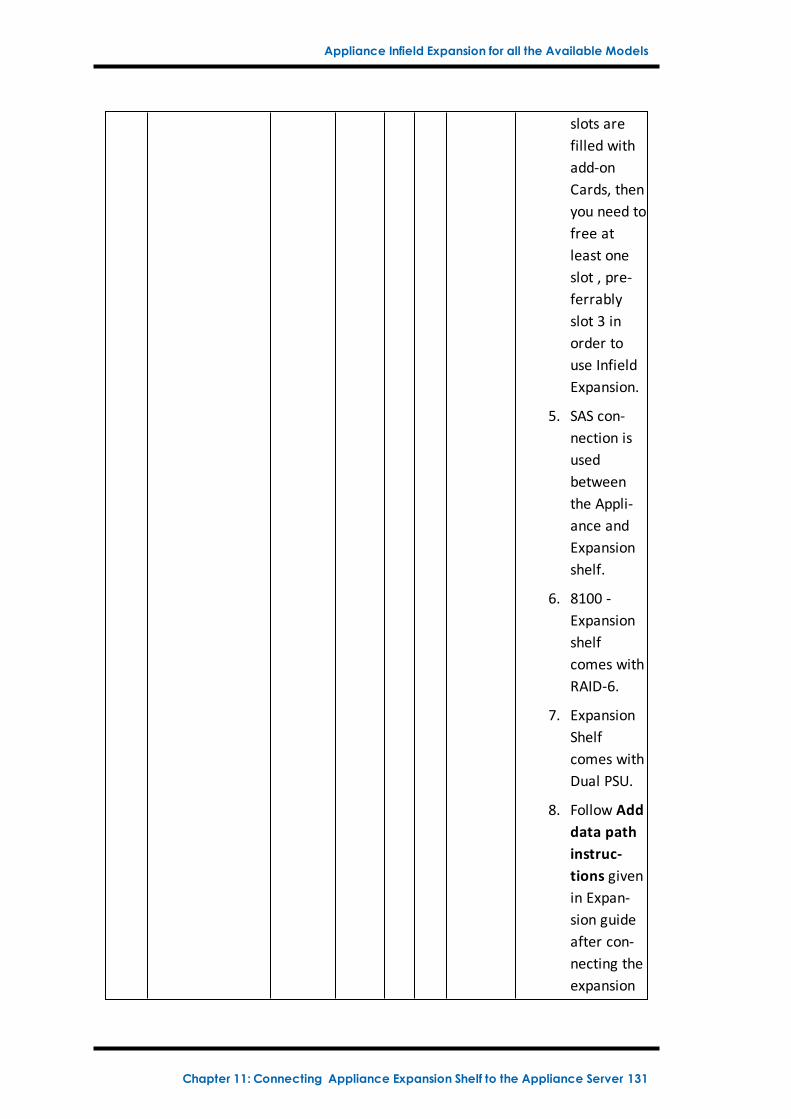
Appliance Infield Expansion for all the Available Models
slots arefilled withadd-onCards, thenyou need tofree atleast oneslot , pre-ferrablyslot 3 inorder touse InfieldExpansion.
5. SAS con-nection isusedbetweenthe Appli-ance andExpansionshelf.
6. 8100 -Expansionshelfcomes withRAID-6.
7. ExpansionShelfcomes withDual PSU.
8. Follow Adddata pathinstruc-tions givenin Expan-sion guideafter con-necting theexpansion
Chapter 11: Connecting Appliance Expansion Shelf to the Appliance Server 131
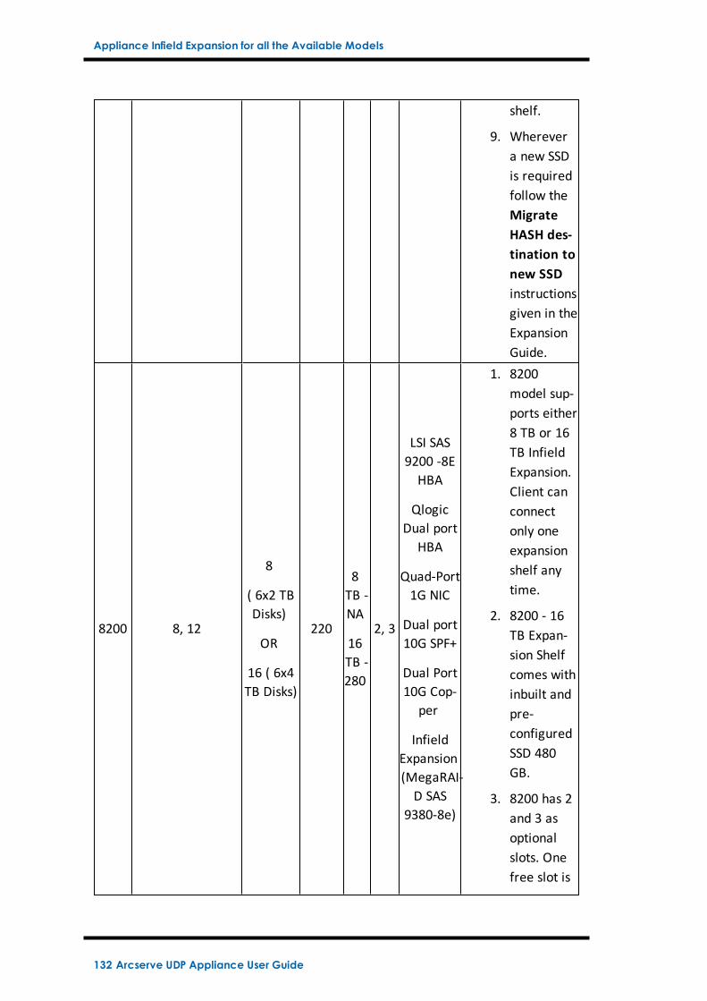
Appliance Infield Expansion for all the Available Models
shelf.
9. Wherevera new SSDis requiredfollow theMigrateHASH des-tination tonew SSDinstructionsgiven in theExpansionGuide.
8200 8, 12
8
( 6x2 TBDisks)
OR
16 ( 6x4TB Disks)
220
8TB -NA
16TB -280
2, 3
LSI SAS9200 -8EHBA
QlogicDual port
HBA
Quad-Port1G NIC
Dual port10G SPF+
Dual Port10G Cop-
per
InfieldExpansion(MegaRAI-D SAS
9380-8e)
1. 8200model sup-ports either8 TB or 16TB InfieldExpansion.Client canconnectonly oneexpansionshelf anytime.
2. 8200 - 16TB Expan-sion Shelfcomes withinbuilt andpre-configuredSSD 480GB.
3. 8200 has 2and 3 asoptionalslots. Onefree slot is
132 Arcserve UDP Appliance User Guide
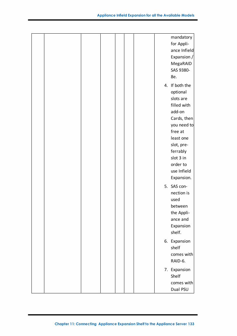
Appliance Infield Expansion for all the Available Models
mandatoryfor Appli-ance InfieldExpansion /MegaRAIDSAS 9380-8e.
4. If both theoptionalslots arefilled withadd-onCards, thenyou need tofree atleast oneslot, pre-ferrablyslot 3 inorder touse InfieldExpansion.
5. SAS con-nection isusedbetweenthe Appli-ance andExpansionshelf.
6. Expansionshelfcomes withRAID-6.
7. ExpansionShelfcomes withDual PSU
Chapter 11: Connecting Appliance Expansion Shelf to the Appliance Server 133
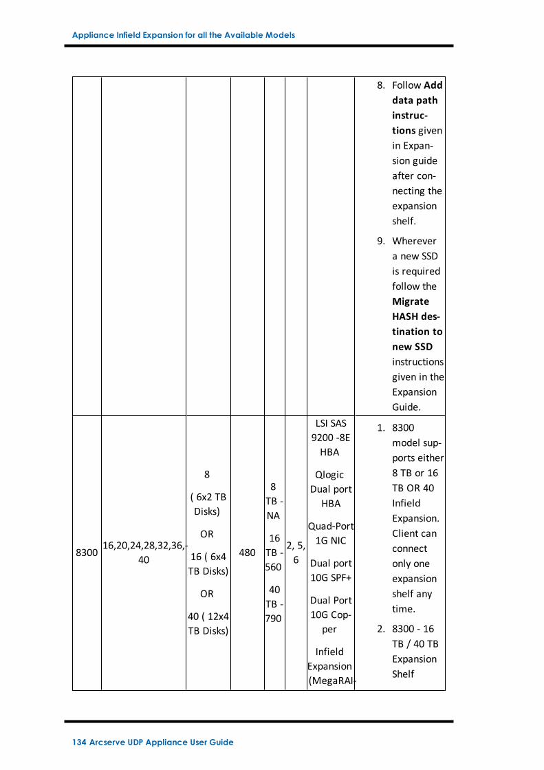
Appliance Infield Expansion for all the Available Models
8. Follow Adddata pathinstruc-tions givenin Expan-sion guideafter con-necting theexpansionshelf.
9. Wherevera new SSDis requiredfollow theMigrateHASH des-tination tonew SSDinstructionsgiven in theExpansionGuide.
830016,20,24,28,32,36,-
40
8
( 6x2 TBDisks)
OR
16 ( 6x4TB Disks)
OR
40 ( 12x4TB Disks)
480
8TB -NA
16TB -560
40TB -790
2, 5,6
LSI SAS9200 -8EHBA
QlogicDual port
HBA
Quad-Port1G NIC
Dual port10G SPF+
Dual Port10G Cop-
per
InfieldExpansion(MegaRAI-
1. 8300model sup-ports either8 TB or 16TB OR 40InfieldExpansion.Client canconnectonly oneexpansionshelf anytime.
2. 8300 - 16TB / 40 TBExpansionShelf
134 Arcserve UDP Appliance User Guide
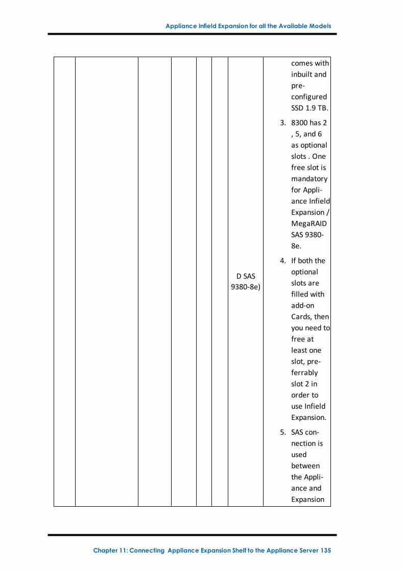
Appliance Infield Expansion for all the Available Models
D SAS9380-8e)
comes withinbuilt andpre-configuredSSD 1.9 TB.
3. 8300 has 2, 5, and 6as optionalslots . Onefree slot ismandatoryfor Appli-ance InfieldExpansion /MegaRAIDSAS 9380-8e.
4. If both theoptionalslots arefilled withadd-onCards, thenyou need tofree atleast oneslot, pre-ferrablyslot 2 inorder touse InfieldExpansion.
5. SAS con-nection isusedbetweenthe Appli-ance andExpansion
Chapter 11: Connecting Appliance Expansion Shelf to the Appliance Server 135
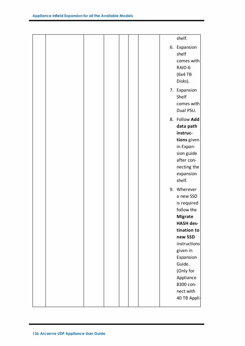
Appliance Infield Expansion for all the Available Models
shelf.
6. Expansionshelfcomes withRAID-6(6x4 TBDisks).
7. ExpansionShelfcomes withDual PSU.
8. Follow Adddata pathinstruc-tions givenin Expan-sion guideafter con-necting theexpansionshelf.
9. Wherevera new SSDis requiredfollow theMigrateHASH des-tination tonew SSDinstructionsgiven inExpansionGuide.(Only forAppliance8300 con-nect with40 TB Appli-
136 Arcserve UDP Appliance User Guide
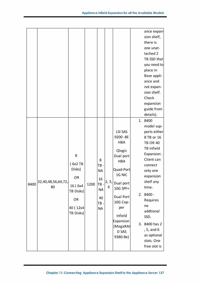
Appliance Infield Expansion for all the Available Models
ance expan-sion shelf,there isone unat-tached 2TB SSD thatyou need toplace inBase appli-ance andnot expan-sion shelf.Checkexpansionguide fromdetails).
840032,40,48,56,64,72,-
80
8
( 6x2 TBDisks)
OR
16 ( 6x4TB Disks)
OR
40 ( 12x4TB Disks)
1200
8TB -NA
16TB -NA
40TB -NA
2, 5,6
LSI SAS9200 -8EHBA
QlogicDual port
HBA
Quad-Port1G NIC
Dual port10G SPF+
Dual Port10G Cop-
per
InfieldExpansion(MegaRAI-D SAS
9380-8e)
1. 8400model sup-ports either8 TB or 16TB OR 40TB InfieldExpansion .Client canconnectonly oneexpansionshelf anytime.
2. 8400 -RequiresnoaddtionalSSD.
3. 8400 has 2, 5, and 6as optionalslots. Onefree slot is
Chapter 11: Connecting Appliance Expansion Shelf to the Appliance Server 137
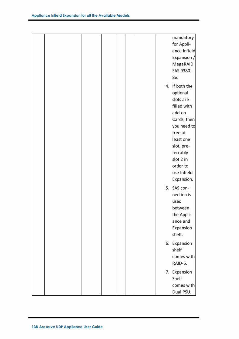
Appliance Infield Expansion for all the Available Models
mandatoryfor Appli-ance InfieldExpansion /MegaRAIDSAS 9380-8e.
4. If both theoptionalslots arefilled withadd-onCards, thenyou need tofree atleast oneslot, pre-ferrablyslot 2 inorder touse InfieldExpansion.
5. SAS con-nection isusedbetweenthe Appli-ance andExpansionshelf.
6. Expansionshelfcomes withRAID-6.
7. ExpansionShelfcomes withDual PSU.
138 Arcserve UDP Appliance User Guide
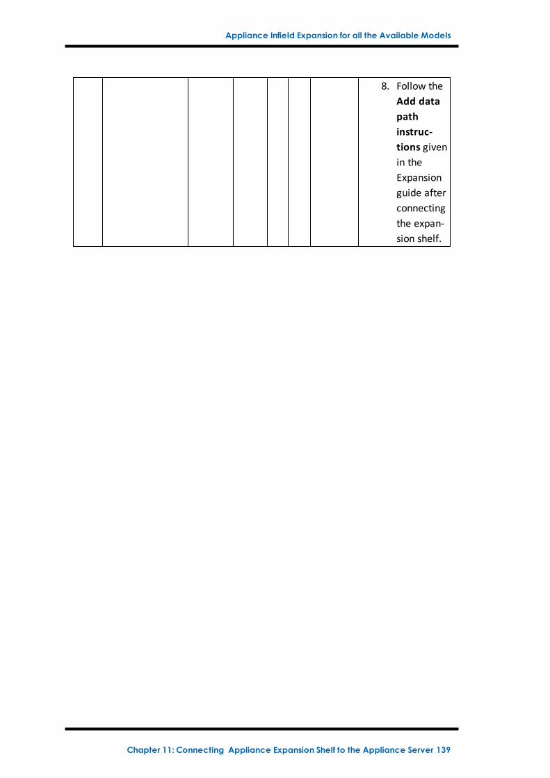
Appliance Infield Expansion for all the Available Models
8. Follow theAdd datapathinstruc-tions givenin theExpansionguide afterconnectingthe expan-sion shelf.
Chapter 11: Connecting Appliance Expansion Shelf to the Appliance Server 139
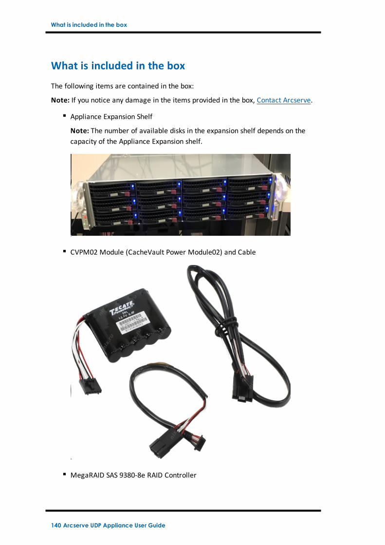
What is included in the box
What is included in the box
The following items are contained in the box:
Note: If you notice any damage in the items provided in the box, Contact Arcserve.
Appliance Expansion Shelf
Note: The number of available disks in the expansion shelf depends on thecapacity of the Appliance Expansion shelf.
CVPM02 Module (CacheVault Power Module02) and Cable
MegaRAID SAS 9380-8e RAID Controller
140 Arcserve UDP Appliance User Guide
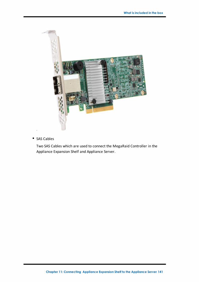
What is included in the box
SAS Cables
Two SAS Cables which are used to connect the MegaRaid Controller in theAppliance Expansion Shelf and Appliance Server.
Chapter 11: Connecting Appliance Expansion Shelf to the Appliance Server 141
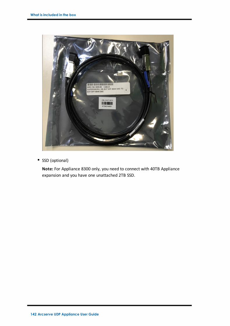
What is included in the box
SSD (optional)
Note: For Appliance 8300 only, you need to connect with 40TB Applianceexpansion and you have one unattached 2TB SSD.
142 Arcserve UDP Appliance User Guide
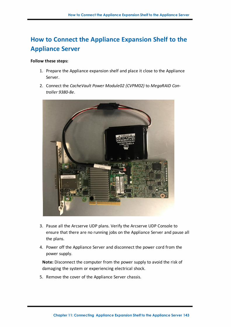
How to Connect the Appliance Expansion Shelf to the Appliance Server
How to Connect the Appliance Expansion Shelf to theAppliance Server
Follow these steps:
1. Prepare the Appliance expansion shelf and place it close to the ApplianceServer.
2. Connect the CacheVault Power Module02 (CVPM02) toMegaRAID Con-troller 9380-8e.
3. Pause all the Arcserve UDP plans. Verify the Arcserve UDP Console toensure that there are no running jobs on the Appliance Server and pause allthe plans.
4. Power off the Appliance Server and disconnect the power cord from thepower supply.
Note: Disconnect the computer from the power supply to avoid the risk ofdamaging the system or experiencing electrical shock.
5. Remove the cover of the Appliance Server chassis.
Chapter 11: Connecting Appliance Expansion Shelf to the Appliance Server 143
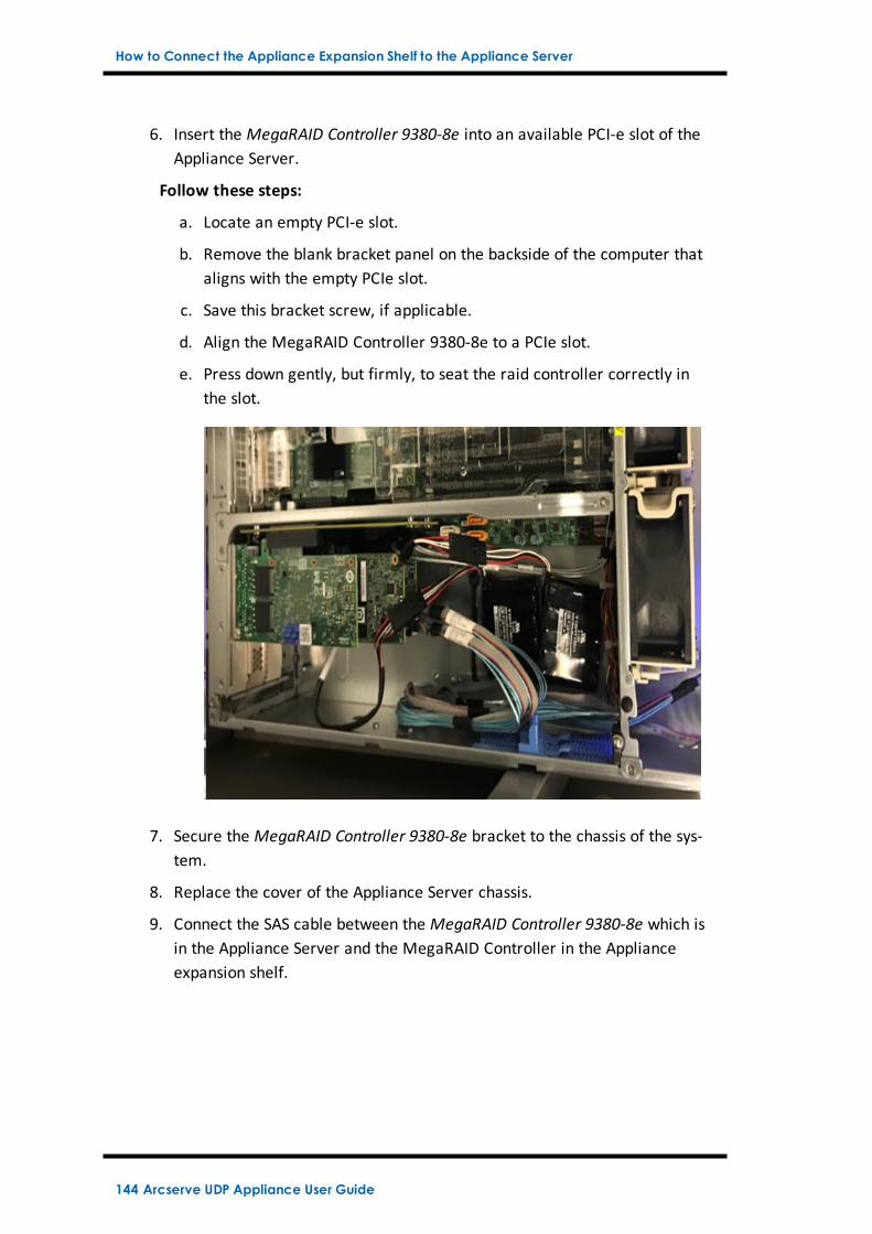
How to Connect the Appliance Expansion Shelf to the Appliance Server
6. Insert the MegaRAID Controller 9380-8e into an available PCI-e slot of theAppliance Server.
Follow these steps:
a. Locate an empty PCI-e slot.
b. Remove the blank bracket panel on the backside of the computer thataligns with the empty PCIe slot.
c. Save this bracket screw, if applicable.
d. Align the MegaRAID Controller 9380-8e to a PCIe slot.
e. Press down gently, but firmly, to seat the raid controller correctly inthe slot.
7. Secure the MegaRAID Controller 9380-8e bracket to the chassis of the sys-tem.
8. Replace the cover of the Appliance Server chassis.
9. Connect the SAS cable between the MegaRAID Controller 9380-8e which isin the Appliance Server and the MegaRAID Controller in the Applianceexpansion shelf.
144 Arcserve UDP Appliance User Guide
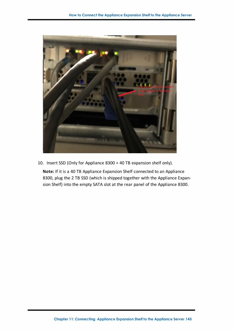
How to Connect the Appliance Expansion Shelf to the Appliance Server
10. Insert SSD (Only for Appliance 8300 + 40 TB expansion shelf only).
Note: If it is a 40 TB Appliance Expansion Shelf connected to an Appliance8300, plug the 2 TB SSD (which is shipped together with the Appliance Expan-sion Shelf) into the empty SATA slot at the rear panel of the Appliance 8300.
Chapter 11: Connecting Appliance Expansion Shelf to the Appliance Server 145
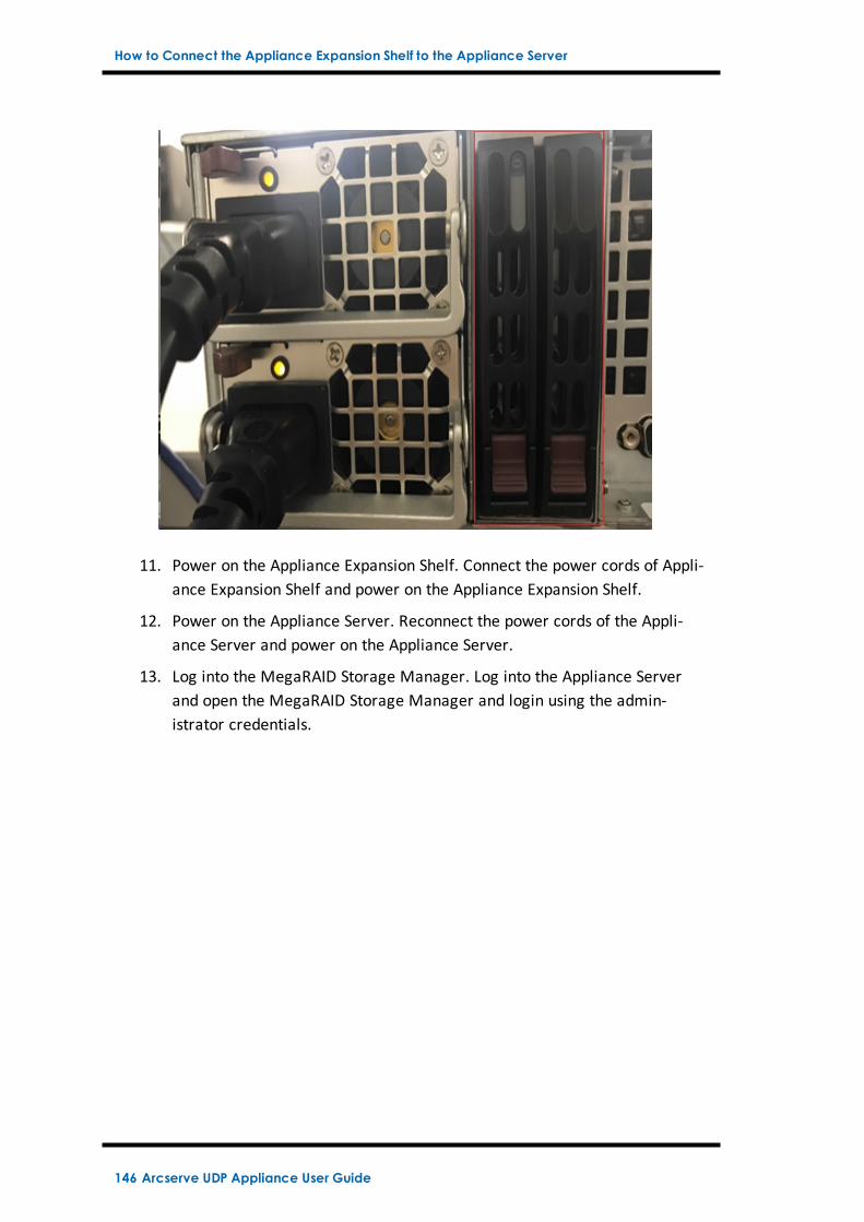
How to Connect the Appliance Expansion Shelf to the Appliance Server
11. Power on the Appliance Expansion Shelf. Connect the power cords of Appli-ance Expansion Shelf and power on the Appliance Expansion Shelf.
12. Power on the Appliance Server. Reconnect the power cords of the Appli-ance Server and power on the Appliance Server.
13. Log into the MegaRAID Storage Manager. Log into the Appliance Serverand open the MegaRAID Storage Manager and login using the admin-istrator credentials.
146 Arcserve UDP Appliance User Guide
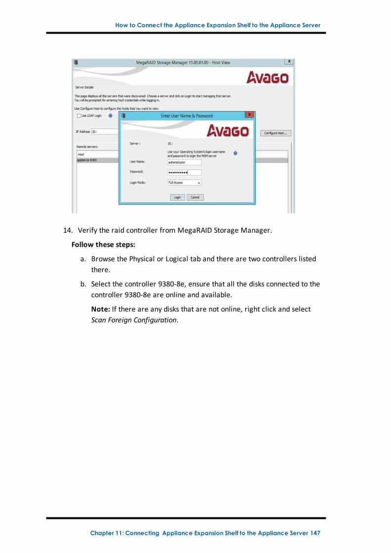
How to Connect the Appliance Expansion Shelf to the Appliance Server
14. Verify the raid controller from MegaRAID Storage Manager.
Follow these steps:
a. Browse the Physical or Logical tab and there are two controllers listedthere.
b. Select the controller 9380-8e, ensure that all the disks connected to thecontroller 9380-8e are online and available.
Note: If there are any disks that are not online, right click and selectScan Foreign Configuration.
Chapter 11: Connecting Appliance Expansion Shelf to the Appliance Server 147
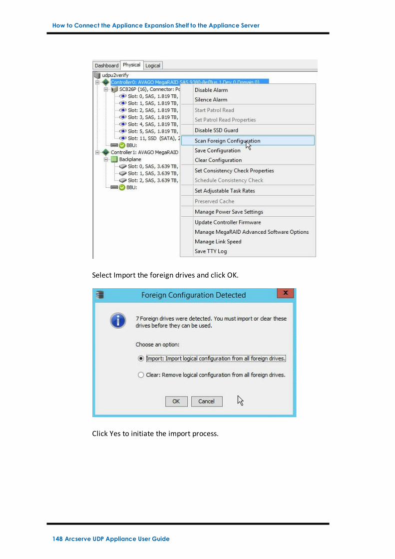
How to Connect the Appliance Expansion Shelf to the Appliance Server
Select Import the foreign drives and click OK.
Click Yes to initiate the import process.
148 Arcserve UDP Appliance User Guide
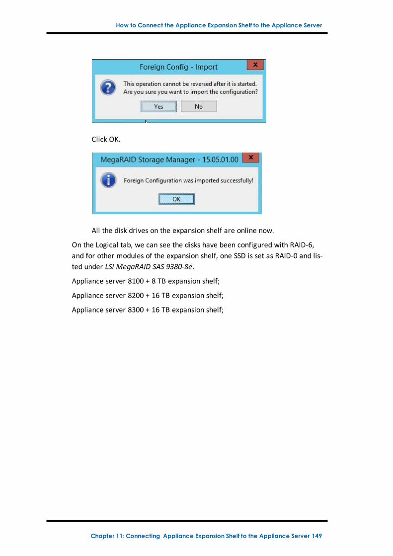
How to Connect the Appliance Expansion Shelf to the Appliance Server
Click OK.
All the disk drives on the expansion shelf are online now.
On the Logical tab, we can see the disks have been configured with RAID-6,and for other modules of the expansion shelf, one SSD is set as RAID-0 and lis-ted under LSI MegaRAID SAS 9380-8e.
Appliance server 8100 + 8 TB expansion shelf;
Appliance server 8200 + 16 TB expansion shelf;
Appliance server 8300 + 16 TB expansion shelf;
Chapter 11: Connecting Appliance Expansion Shelf to the Appliance Server 149
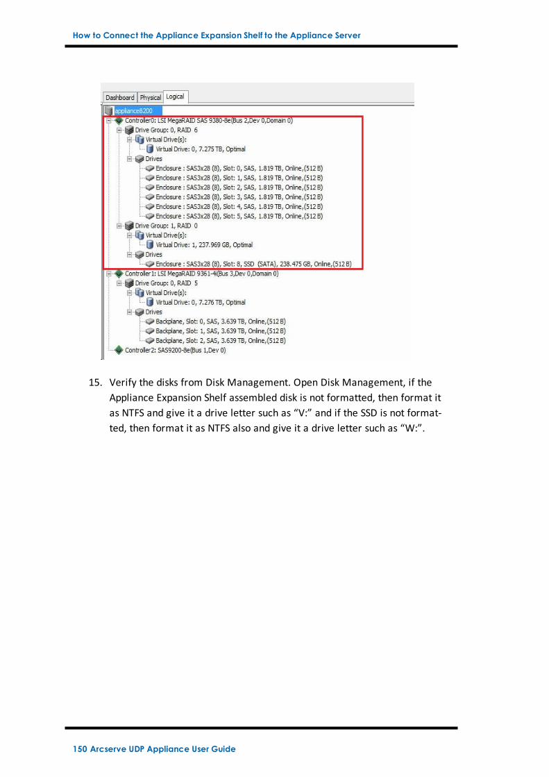
How to Connect the Appliance Expansion Shelf to the Appliance Server
15. Verify the disks from Disk Management. Open Disk Management, if theAppliance Expansion Shelf assembled disk is not formatted, then format itas NTFS and give it a drive letter such as “V:” and if the SSD is not format-ted, then format it as NTFS also and give it a drive letter such as “W:”.
150 Arcserve UDP Appliance User Guide
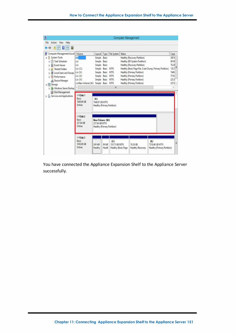
How to Connect the Appliance Expansion Shelf to the Appliance Server
You have connected the Appliance Expansion Shelf to the Appliance Serversuccessfully.
Chapter 11: Connecting Appliance Expansion Shelf to the Appliance Server 151
How to Modify Arcserve UDP Data store
How to Modify Arcserve UDP Data store
This section contains the following topics:
Adding a data path on the expansion shelf to the Arcserve UDP data store
Migrating Hash Destination to the new SSD
Checking the overall capacity of the <hostname_data_store> data store fromthe Arcserve UDP Console
Resuming all the plans from Arcserve UDP Console
152 Arcserve UDP Appliance User Guide
How to Modify Arcserve UDP Data store
Adding a data path on the expansion shelf to the Arc-serve UDP data store
Follow these steps:
1. Create a folder in the volume on the Appliance expansion shelf, such as“V:\data”.
2. Stop the data store and use the following command to expand the datastore to the Appliance expansion shelf:
as_gddmgr.exe –DataPath Add <hostname_data_store> -NewDataPath <newdata folder>
as_gddmgr.exe –DataPath Display <hostname_data_store>
Chapter 11: Connecting Appliance Expansion Shelf to the Appliance Server 153
How to Modify Arcserve UDP Data store
Migrating Hash Destination to the new SSD
Note: This step is only required when you use a new SSD for the following expan-sion shelf:
Appliance server 8100 + 8 TB expansion shelf;
Appliance server 8200 + 16 TB expansion shelf;
Appliance server 8300 + 16 TB expansion shelf;
Appliance server 8300 + 40 TB expansion shelf;
Follow these steps:
1. Create a hash folder on the new SSD such asW:\Arcserve\data_store\hash.
2. Ensure the data store <hostname_data_store> is stopped. If not, stop thedata store <hostname_data_store> from the Arcserve UDP Console.
3. Modify the data store <hostname_data_store> from the Arcserve UDP Con-sole and set the Hash Destination toW:\Arcserve\data_store\hash.
4. Save the modification of the data store.
5. Start the data store <hostname_data_store> from the Arcserve UDP Con-sole.
154 Arcserve UDP Appliance User Guide
How to Modify Arcserve UDP Data store
Checking the overall capacity of the <hostname_data_store> data store from the Arcserve UDP Con-sole
The overall capacity is the capacity of the Appliance server plus the capacity of theAppliance expansion shelf.
Chapter 11: Connecting Appliance Expansion Shelf to the Appliance Server 155
How to Modify Arcserve UDP Data store
Resuming all the plans from Arcserve UDP Console
Resume all the paused plans from the Arcserve UDP Console.
156 Arcserve UDP Appliance User Guide
Chapter 12: TroubleshootingThis section contains the following topics:
Linux Backup Server Fails to Connect from the Console 158
Backing Up a UDP Appliance from Another Appliance Reports Duplicated Nodes 160
Linux Backup Server Cannot Get the Network DNS Suffix 162
Default Time Zone on the Appliance 163
Licenses Error even when the licenses are available 164
Chapter 12: Troubleshooting 157
Linux Backup Server Fails to Connect from the Console
Linux Backup Server Fails to Connect from the Con-sole
Symptom
When I try to connect my Linux Backup Server from the Arcserve UDP Console, con-nection is unsuccessful and I see a red mark.
Solution
When a Linux Backup Server fails to connect from the console, you cantroubleshoot the connection to determine the problem.
To troubleshoot the connectivity issue
1. Launch the Hyper-V Manager, connect the Linux Backup Server virtualmachine and login.
2. Run the following command:
service network restart
3. Verify that the IP address assigned to the Linux Backup Server is 192.168.10.2.To verify, run the following command:
ifconfig
4. If the IP address is 192.168.10.2, navigate to the Arcserve UDP Console andupdate the Linux Backup Server node that you are trying to connect.
5. If the IP address is not 192.168.10.2, follow the instructions in theTroubleshoot from DHCP Microsoft Management Console (MMC) section.
Troubleshoot from DHCP Microsoft Management Console (MMC)
Important! Ensure that the DHCP Server service is running appropriately on theappliance.
1. Launch DHCP MMC from the Server Manager, Tools, DHCP.
2. Expand the Linux Server node, IPV4, Scope and ensure that the scope with thename 192.168.10.0 exists under it.
3. Expand the Address Leases and delete the presence of any other lease record.
4. Log into the Linux Backup Server and run the following command:
service network restart
5. Navigate to the Arcserve UDP Console and update the Linux Backup Servernode that you are trying to connect.
158 Arcserve UDP Appliance User Guide
Linux Backup Server Fails to Connect from the Console
The Linux Backup Server now connects from the Console.
Chapter 12: Troubleshooting 159
Backing Up a UDP Appliance from Another Appliance Reports Duplicated Nodes
Backing Up a UDP Appliance from Another ApplianceReports Duplicated Nodes
Symptom
When I back up Appliance B from Appliance A, I see the following warning messagein the activity log:
"The following nodes are duplicated: Appliance_B, Appliance_A. As a result, theyhave the same agent identifier and may cause unexpected results. This duplicatenode problem can be caused if the node was added using a different node name(such as the DNS name or IP address), or if some machines were set up by cloningfrom one to another."
Case 1: Appliance B is added as an RPS to the Appliance A UDP Console.
For example: From Appliance B, you can configure the appliance using the UDP wiz-ard and select "This appliance will function as an instance of Arcserve UDP Recov-ery Point Server managed by another Arcserve UDP console."
Solution
1. Stop the data store in the Appliance B node from the RPS pane of the UDP con-sole.
2. Log into Appliance B and delete the registry key of the Node ID that is locatedunder [HKEY_LOCAL_MACHINE\SOFTWARE\CA\ARCserve Unified Data Pro-tection\Engine].
3. Restart the Arcserve UDP Agent Web Service from the Appliance B node.
4. Restart the Arcserve UDP RPS Data Store Service from the Appliance B node.
5. From the UDP console, go to the Nodes, All Nodes pane and update the Appli-ance B node.
6. Go to the Recovery Point Server pane and update the Appliance B node.
7. Import the existing data store to the Appliance B RPS by setting it with the ori-ginal backup destination.
Case 2: Appliance B is added only as an agent node to the Appliance A UDP Con-sole.
For example, a plan protects Appliance B through an agent-based backup task onthe Appliance A UDP console.
1. Log into Appliance B and delete the registry key of the Node ID that is locatedunder [HKEY_LOCAL_MACHINE\SOFTWARE\Arcserve Unified Data
160 Arcserve UDP Appliance User Guide
Backing Up a UDP Appliance from Another Appliance Reports Duplicated Nodes
Protection\Engine].
2. Restart the Arcserve UDP Agent service from Appliance B.
3. From the UDP console, go to the Nodes, All Nodes pane and update the nodefrom Appliance B.
Chapter 12: Troubleshooting 161
Linux Backup Server Cannot Get the Network DNS Suffix
Linux Backup Server Cannot Get the Network DNSSuffix
When you set the static IP address to the appliance Server, the Linux Backup Servercannot get the network DNS suffix properly after restarting the network service.This issue leads to communication problems between the Linux backup Server andthe UDP console. You then cannot use this Linux backup Server to protect the Linuxnode due to the communication problems.
Symptom
The status of the Linux Backup Server remains in a disconnected state on the UDPconsole. The Update Node cannot update the Linux Backup Server successfully andthe yellow warning icon will not change to green. This occurs when you set thestatic IP address to the appliance Server which will then cause the Linux BackupServer to not get the network DNS suffix properly.
Solution
To resolve this issue, you can update the file/etc/resolv.conf directly in the Linuxmachine to add the correct DNS suffix.
162 Arcserve UDP Appliance User Guide
Default Time Zone on the Appliance
Default Time Zone on the Appliance
Symptom
The default time zone is (UTC-08:00) Pacific Time (US & Canada) no matter whatregion you select when you first power on the appliance.
Solution
To resolve this issue, go to the Arcserve Backup Appliance Wizard and click Edit,Date and Time to change the time zone.
Chapter 12: Troubleshooting 163
Licenses Error even when the licenses are available
Licenses Error even when the licenses are available
For more information on license related errors in the Appliance even when thelicenses are available, refer the link.
164 Arcserve UDP Appliance User Guide
Chapter 13: Best PracticesThis section contains the following topics:
Best Practices for Network Configuration 166
Best Practices for Arcserve UDP ConsoleMigration 169
Best Practices for Set Appliance Image Utility Tool 171
Best Practices for pre-installed Linux Backup Server in the Arcserve UDP Appliance 174
Best Practices for Arcserve UDP Appliance to backup the Linux Backup Server itself 176
Best Practices to Migrate from Arcserve UDP Appliance to Appliance 180
Solution 1 181
Solution 2 185
Best Practices for Arcserve UDP Linux instant VM job to Local Appliance Hyper-V 187
Best Practices to add Replicate to a remotely managed RPS task to another Appli-ance 188
Best Practices to perform Virtual Standby (VSB) task for which themonitor is anotherAppliance 190
Chapter 13: Best Practices 165
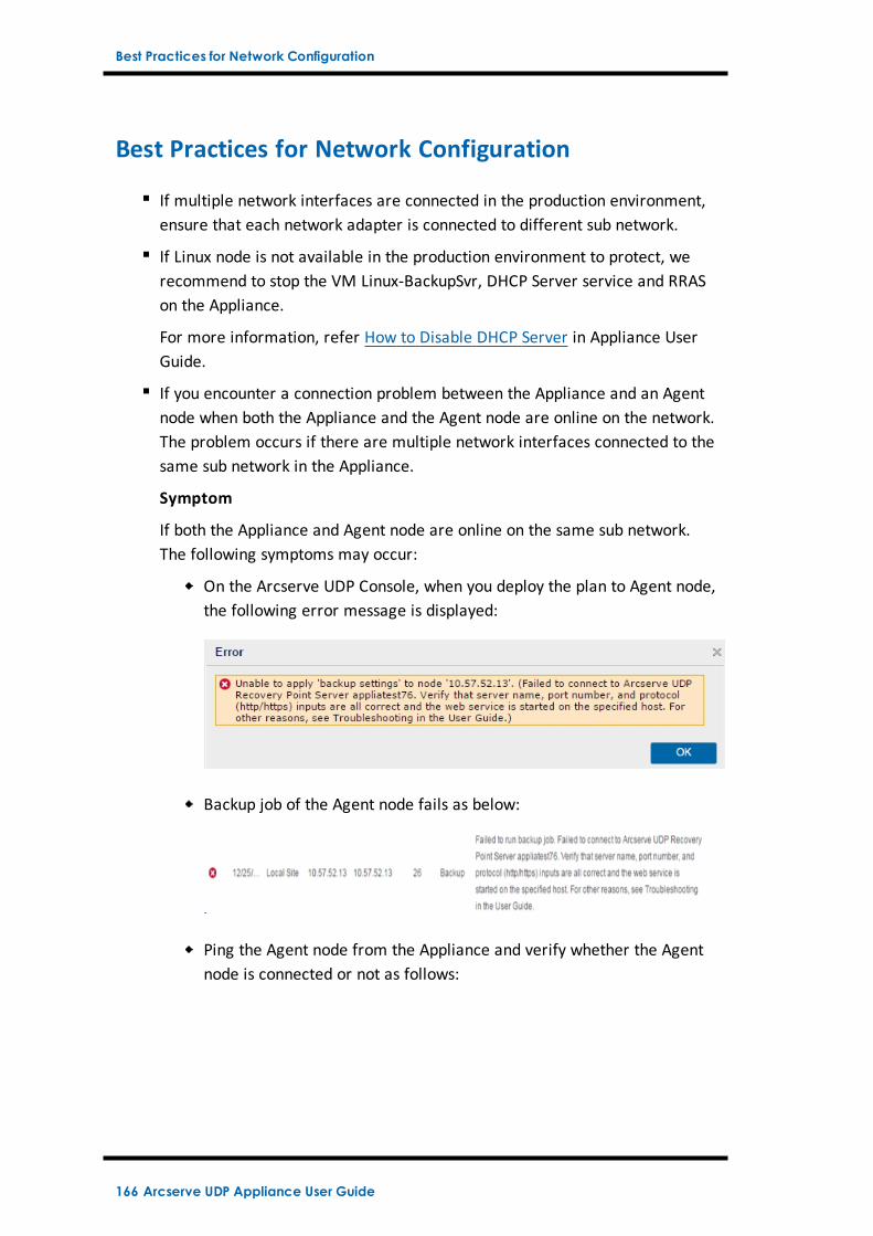
Best Practices for Network Configuration
Best Practices for Network Configuration
If multiple network interfaces are connected in the production environment,ensure that each network adapter is connected to different sub network.
If Linux node is not available in the production environment to protect, werecommend to stop the VM Linux-BackupSvr, DHCP Server service and RRASon the Appliance.
For more information, refer How to Disable DHCP Server in Appliance UserGuide.
If you encounter a connection problem between the Appliance and an Agentnode when both the Appliance and the Agent node are online on the network.The problem occurs if there are multiple network interfaces connected to thesame sub network in the Appliance.
Symptom
If both the Appliance and Agent node are online on the same sub network.The following symptoms may occur:
On the Arcserve UDP Console, when you deploy the plan to Agent node,the following error message is displayed:
Backup job of the Agent node fails as below:
Ping the Agent node from the Appliance and verify whether the Agentnode is connected or not as follows:
166 Arcserve UDP Appliance User Guide
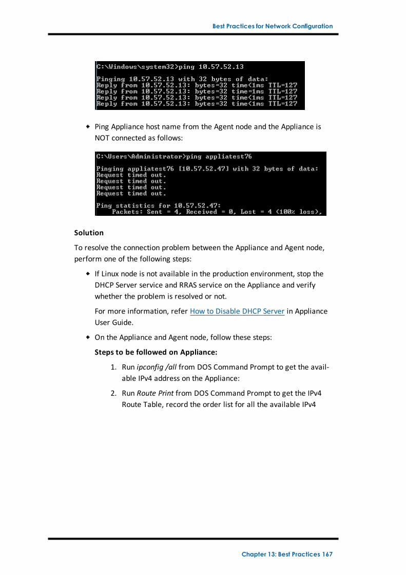
Best Practices for Network Configuration
Ping Appliance host name from the Agent node and the Appliance isNOT connected as follows:
Solution
To resolve the connection problem between the Appliance and Agent node,perform one of the following steps:
If Linux node is not available in the production environment, stop theDHCP Server service and RRAS service on the Appliance and verifywhether the problem is resolved or not.
For more information, refer How to Disable DHCP Server in ApplianceUser Guide.
On the Appliance and Agent node, follow these steps:
Steps to be followed on Appliance:
1. Run ipconfig /all from DOS Command Prompt to get the avail-able IPv4 address on the Appliance:
2. Run Route Print from DOS Command Prompt to get the IPv4Route Table, record the order list for all the available IPv4
Chapter 13: Best Practices 167
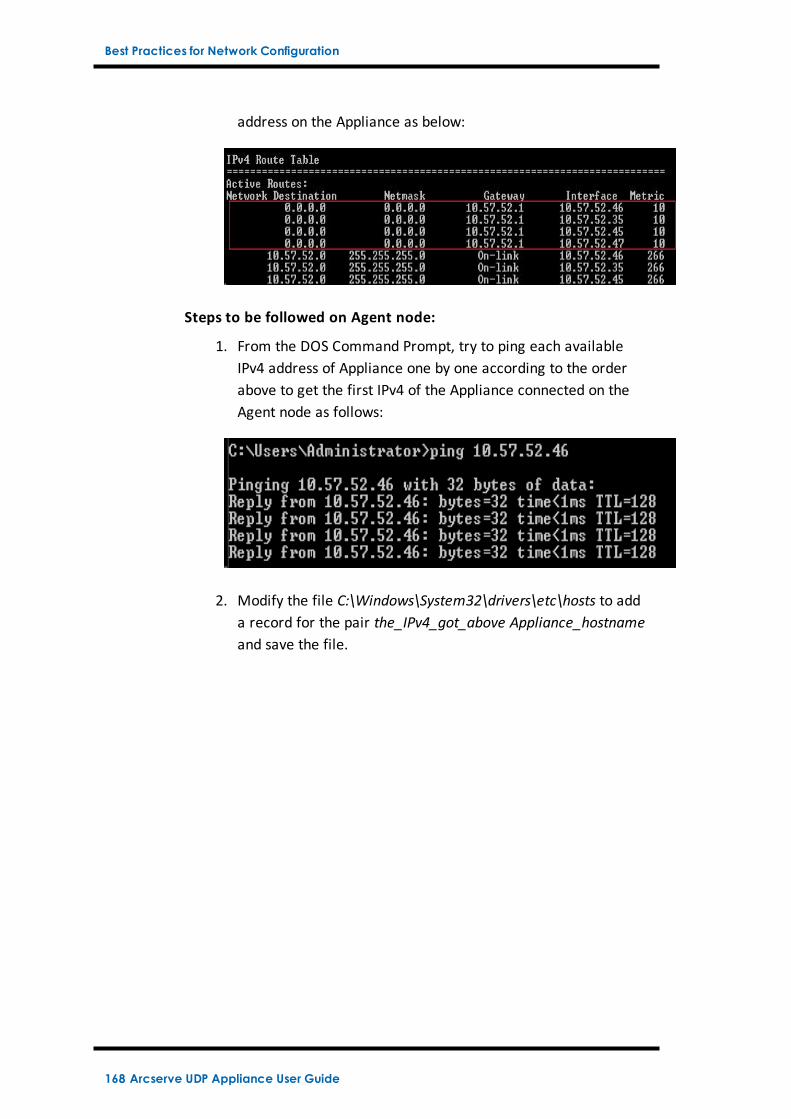
Best Practices for Network Configuration
address on the Appliance as below:
Steps to be followed on Agent node:
1. From the DOS Command Prompt, try to ping each availableIPv4 address of Appliance one by one according to the orderabove to get the first IPv4 of the Appliance connected on theAgent node as follows:
2. Modify the file C:\Windows\System32\drivers\etc\hosts to adda record for the pair the_IPv4_got_above Appliance_hostnameand save the file.
168 Arcserve UDP Appliance User Guide
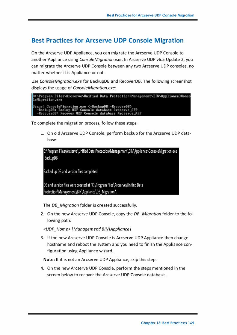
Best Practices for Arcserve UDP Console Migration
Best Practices for Arcserve UDP Console Migration
On the Arcserve UDP Appliance, you can migrate the Arcserve UDP Console toanother Appliance using ConsoleMigration.exe. In Arcserve UDP v6.5 Update 2, youcan migrate the Arcserve UDP Console between any two Arcserve UDP consoles, nomatter whether it is Appliance or not.
Use ConsoleMigration.exe for BackupDB and RecoverDB. The following screenshotdisplays the usage of ConsoleMigration.exe:
To complete the migration process, follow these steps:
1. On old Arcserve UDP Console, perform backup for the Arcserve UDP data-base.
The DB_Migration folder is created successfully.
2. On the new Arcserve UDP Console, copy the DB_Migration folder to the fol-lowing path:
<UDP_Home> \Management\BIN\Appliance\
3. If the new Arcserve UDP Console is Arcserve UDP Appliance then changehostname and reboot the system and you need to finish the Appliance con-figuration using Appliance wizard.
Note: If it is not an Arcserve UDP Appliance, skip this step.
4. On the new Arcserve UDP Console, perform the steps mentioned in thescreen below to recover the Arcserve UDP Console database.
Chapter 13: Best Practices 169
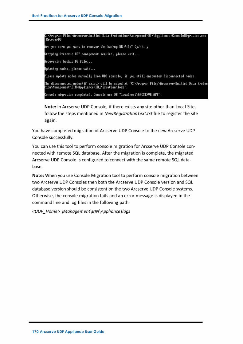
Best Practices for Arcserve UDP Console Migration
Note: In Arcserve UDP Console, if there exists any site other than Local Site,follow the steps mentioned in NewRegistrationText.txt file to register the siteagain.
You have completed migration of Arcserve UDP Console to the new Arcserve UDPConsole successfully.
You can use this tool to perform console migration for Arcserve UDP Console con-nected with remote SQL database. After the migration is complete, the migratedArcserve UDP Console is configured to connect with the same remote SQL data-base.
Note:When you use Console Migration tool to perform console migration betweentwo Arcserve UDP Consoles then both the Arcserve UDP Console version and SQLdatabase version should be consistent on the two Arcserve UDP Console systems.Otherwise, the console migration fails and an error message is displayed in thecommand line and log files in the following path:
<UDP_Home> \Management\BIN\Appliance\logs
170 Arcserve UDP Appliance User Guide
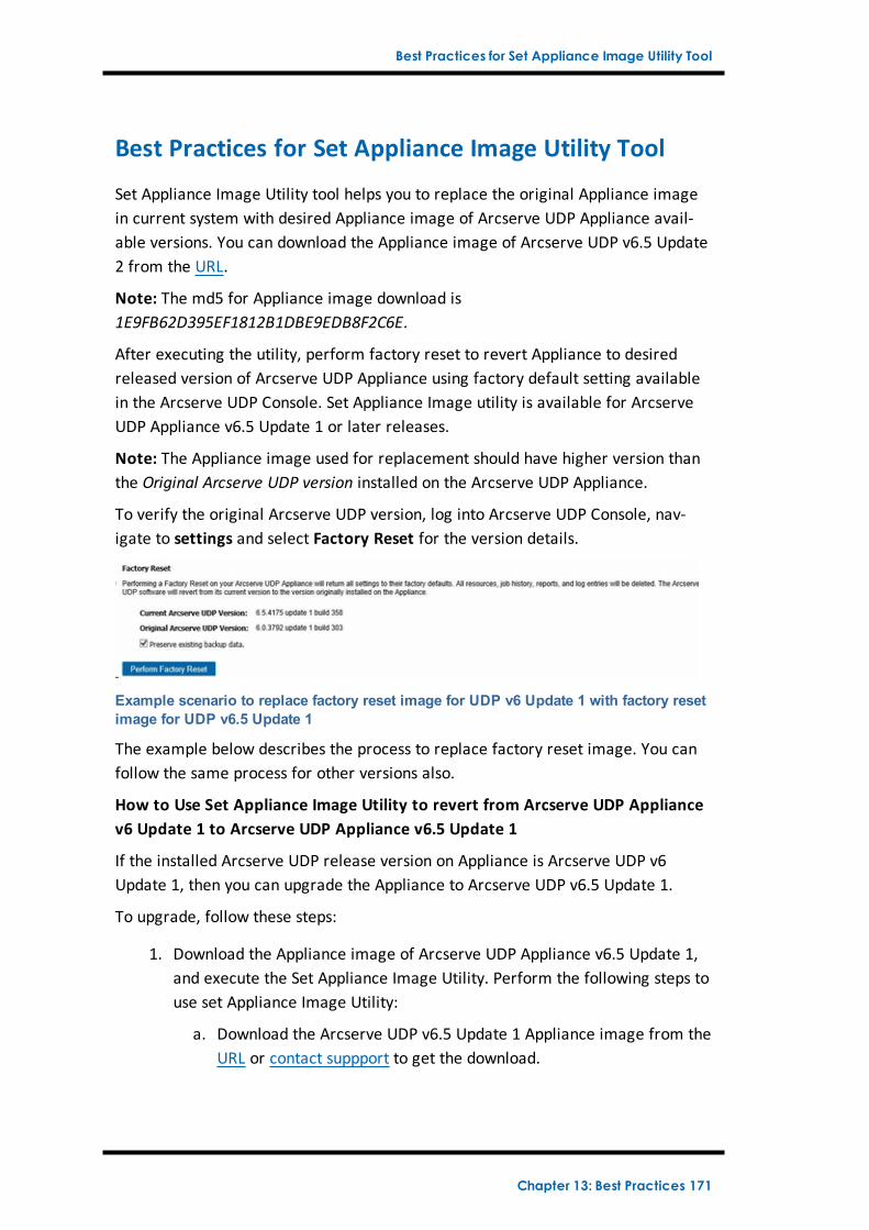
Best Practices for Set Appliance Image Utility Tool
Best Practices for Set Appliance Image Utility Tool
Set Appliance Image Utility tool helps you to replace the original Appliance imagein current system with desired Appliance image of Arcserve UDP Appliance avail-able versions. You can download the Appliance image of Arcserve UDP v6.5 Update2 from the URL.
Note: The md5 for Appliance image download is1E9FB62D395EF1812B1DBE9EDB8F2C6E.
After executing the utility, perform factory reset to revert Appliance to desiredreleased version of Arcserve UDP Appliance using factory default setting availablein the Arcserve UDP Console. Set Appliance Image utility is available for ArcserveUDP Appliance v6.5 Update 1 or later releases.
Note: The Appliance image used for replacement should have higher version thanthe Original Arcserve UDP version installed on the Arcserve UDP Appliance.
To verify the original Arcserve UDP version, log into Arcserve UDP Console, nav-igate to settings and select Factory Reset for the version details.
Example scenario to replace factory reset image for UDP v6 Update 1 with factory resetimage for UDP v6.5 Update 1
The example below describes the process to replace factory reset image. You canfollow the same process for other versions also.
How to Use Set Appliance Image Utility to revert from Arcserve UDP Appliancev6 Update 1 to Arcserve UDP Appliance v6.5 Update 1
If the installed Arcserve UDP release version on Appliance is Arcserve UDP v6Update 1, then you can upgrade the Appliance to Arcserve UDP v6.5 Update 1.
To upgrade, follow these steps:
1. Download the Appliance image of Arcserve UDP Appliance v6.5 Update 1,and execute the Set Appliance Image Utility. Perform the following steps touse set Appliance Image Utility:
a. Download the Arcserve UDP v6.5 Update 1 Appliance image from theURL or contact suppport to get the download.
Chapter 13: Best Practices 171
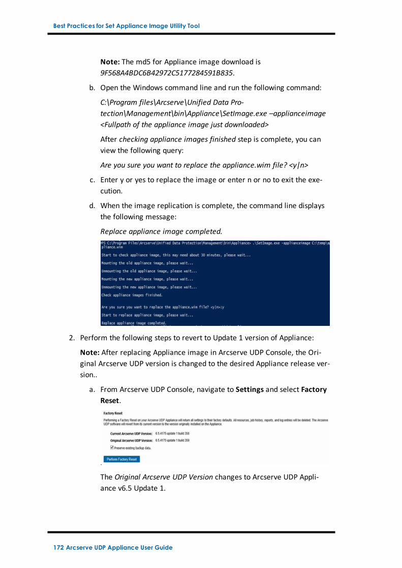
Best Practices for Set Appliance Image Utility Tool
Note: The md5 for Appliance image download is9F568A4BDC6B42972C5177284591B835.
b. Open the Windows command line and run the following command:
C:\Program files\Arcserve\Unified Data Pro-tection\Management\bin\Appliance\SetImage.exe –applianceimage<Fullpath of the appliance image just downloaded>
After checking appliance images finished step is complete, you canview the following query:
Are you sure you want to replace the appliance.wim file? <y|n>
c. Enter y or yes to replace the image or enter n or no to exit the exe-cution.
d. When the image replication is complete, the command line displaysthe following message:
Replace appliance image completed.
2. Perform the following steps to revert to Update 1 version of Appliance:
Note: After replacing Appliance image in Arcserve UDP Console, the Ori-ginal Arcserve UDP version is changed to the desired Appliance release ver-sion..
a. From Arcserve UDP Console, navigate to Settings and select FactoryReset.
The Original Arcserve UDP Version changes to Arcserve UDP Appli-ance v6.5 Update 1.
172 Arcserve UDP Appliance User Guide
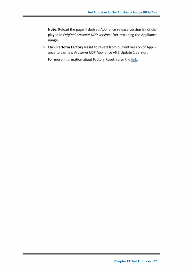
Best Practices for Set Appliance Image Utility Tool
Note: Reload the page if desired Appliance release version is not dis-played in Original Arcserve UDP version after replacing the Applianceimage.
b. Click Perform Factory Reset to revert from current version of Appli-ance to the new Arcserve UDP Appliance v6.5 Update 1 version.
For more information about Factory Reset, refer the link.
Chapter 13: Best Practices 173
Best Practices for pre-installed Linux Backup Server in the Arcserve UDP Appliance
Best Practices for pre-installed Linux Backup Server inthe Arcserve UDP Appliance
If you upgrade the Arcserve UDP Appliance pre-installed Linux Backup Server tov6.5 Update 2, then you need to manually add some ports to Linux which is CentOS6.6 x64 firewall after the upgrade.
Follow these steps:
1. Navigate to the following path:
vi /etc/sysconfig/iptables
2. The iptables file must contain the following lines that are mentioned inbold, if not you need to add them maually:
# Firewall configuration written by system-config-firewall
# Manual customization of this file is not recommended.
*filter
:INPUT ACCEPT [0:0]
:FORWARD ACCEPT [0:0]
:OUTPUT ACCEPT [0:0]
-A INPUT -p tcp -m tcp --dport 22 -j ACCEPT
-A INPUT -p tcp -m tcp --dport 67 -j ACCEPT
-A INPUT -p tcp -m tcp --dport 69 -j ACCEPT
-A INPUT -p tcp -m tcp --dport 8014 -j ACCEPT
-A INPUT -p tcp -m tcp --dport 8016 -j ACCEPT
-A INPUT -p tcp -m tcp --dport 8017 -j ACCEPT
-A INPUT -p tcp -m tcp --dport 8021 -j ACCEPT
-A INPUT -p tcp -m tcp --dport 8035 -j ACCEPT
-A INPUT -p tcp -m tcp --dport 8036 -j ACCEPT
-A INPUT -p tcp -m tcp --dport 50000 -j ACCEPT
-A INPUT -p tcp -m tcp --dport 50001 -j ACCEPT
-A INPUT -p tcp -m tcp --dport 50002 -j ACCEPT
-A INPUT -p tcp -m tcp --dport 50003 -j ACCEPT
-A INPUT -p tcp -m tcp --dport 50004 -j ACCEPT
174 Arcserve UDP Appliance User Guide
Best Practices for pre-installed Linux Backup Server in the Arcserve UDP Appliance
-A INPUT -m state --state ESTABLISHED,RELATED -j ACCEPT
-A INPUT -p icmp -j ACCEPT
-A INPUT -i lo -j ACCEPT
-A INPUT -m state --state NEW -m tcp -p tcp --dport 22 -j ACCEPT
-A INPUT -j REJECT --reject-with icmp-host-prohibited
-A FORWARD -j REJECT --reject-with icmp-host-prohibited
COMMIT
3. Save the iptables file.
4. Restart the iptables service using the following command:
/etc/init.d/iptables restart
You have added the ports to CentOS 6.6 x64 firewall successfully.
Chapter 13: Best Practices 175
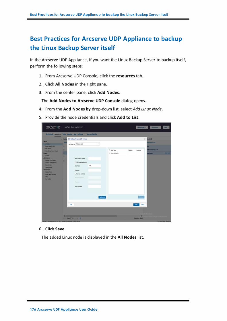
Best Practices for Arcserve UDP Appliance to backup the Linux Backup Server itself
Best Practices for Arcserve UDP Appliance to backupthe Linux Backup Server itself
In the Arcserve UDP Appliance, if you want the Linux Backup Server to backup itself,perform the following steps:
1. From Arcserve UDP Console, click the resources tab.
2. Click All Nodes in the right pane.
3. From the center pane, click Add Nodes.
The Add Nodes to Arcserve UDP Console dialog opens.
4. From the Add Nodes by drop-down list, select Add Linux Node.
5. Provide the node credentials and click Add to List.
6. Click Save.
The added Linux node is displayed in the All Nodes list.
176 Arcserve UDP Appliance User Guide
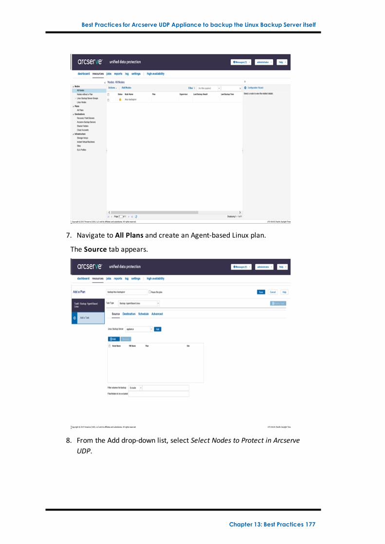
Best Practices for Arcserve UDP Appliance to backup the Linux Backup Server itself
7. Navigate to All Plans and create an Agent-based Linux plan.
The Source tab appears.
8. From the Add drop-down list, select Select Nodes to Protect in ArcserveUDP.
Chapter 13: Best Practices 177
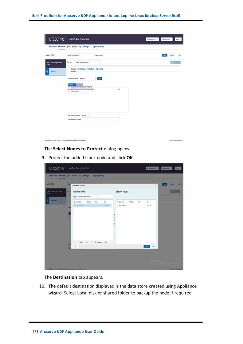
Best Practices for Arcserve UDP Appliance to backup the Linux Backup Server itself
The Select Nodes to Protect dialog opens.
9. Protect the added Linux node and click OK.
The Destination tab appears.
10. The default destination displayed is the data store created using Appliancewizard. Select Local disk or shared folder to backup the node if required.
178 Arcserve UDP Appliance User Guide
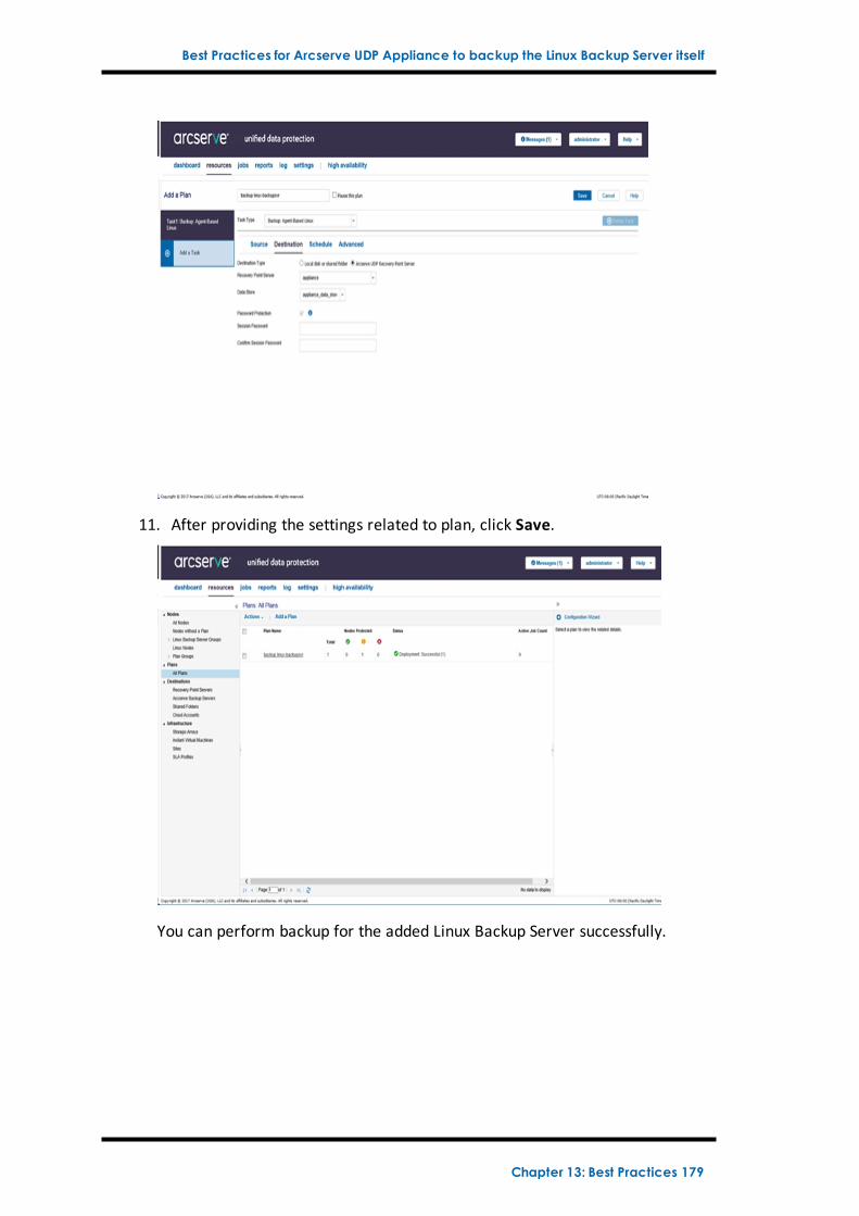
Best Practices for Arcserve UDP Appliance to backup the Linux Backup Server itself
11. After providing the settings related to plan, click Save.
You can perform backup for the added Linux Backup Server successfully.
Chapter 13: Best Practices 179
Best Practices to Migrate from Arcserve UDP Appliance to Appliance
Best Practices to Migrate from Arcserve UDP Appli-ance to Appliance
This topic provides two solutions for user to perform migration from existing Arc-serve UDPAppliance to another fresh Arcserve UDP Appliance.
For example, let us migrate the Arcserve UDP Appliance 8200 to Arcserve UDPAppliance 8400. The prerequisites are listed as follows:
Ensure that you can connect to both Appliance 8200 and Appliance 8400.
Capacity of the new Appliance should have enough memory to hold all thedata on the original Appliance.
In the Arcserve UDP Appliance 8200, ensure that no job runs.
For more information on Console migration, refer the Best Practices for Arc-serve UDP Console Migration topic.
To migrate from any Appliance to a fresh Appliance, you have two solutions as lis-ted below.
Solution 1
Solution 2
180 Arcserve UDP Appliance User Guide
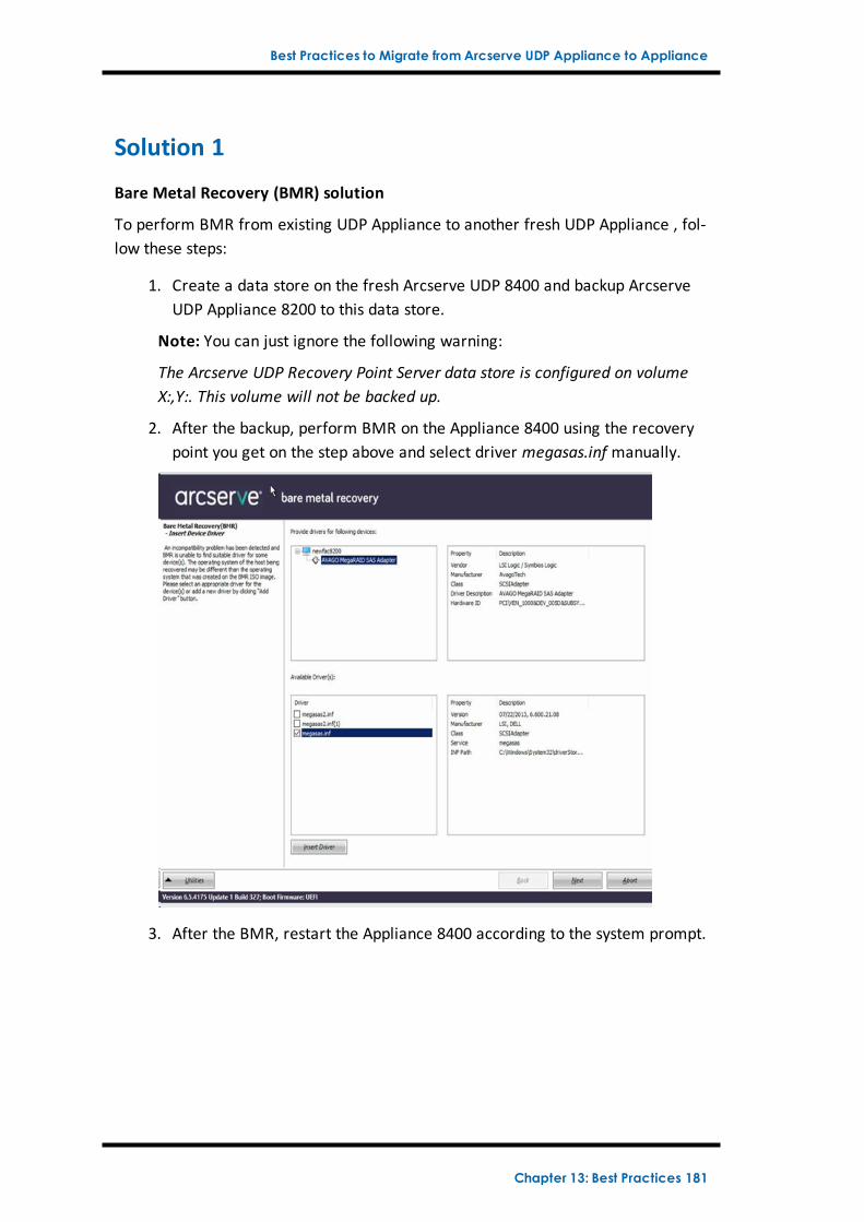
Best Practices to Migrate from Arcserve UDP Appliance to Appliance
Solution 1
Bare Metal Recovery (BMR) solution
To perform BMR from existing UDP Appliance to another fresh UDP Appliance , fol-low these steps:
1. Create a data store on the fresh Arcserve UDP 8400 and backup ArcserveUDP Appliance 8200 to this data store.
Note: You can just ignore the following warning:
The Arcserve UDP Recovery Point Server data store is configured on volumeX:,Y:. This volume will not be backed up.
2. After the backup, perform BMR on the Appliance 8400 using the recoverypoint you get on the step above and select driver megasas.inf manually.
3. After the BMR, restart the Appliance 8400 according to the system prompt.
Chapter 13: Best Practices 181
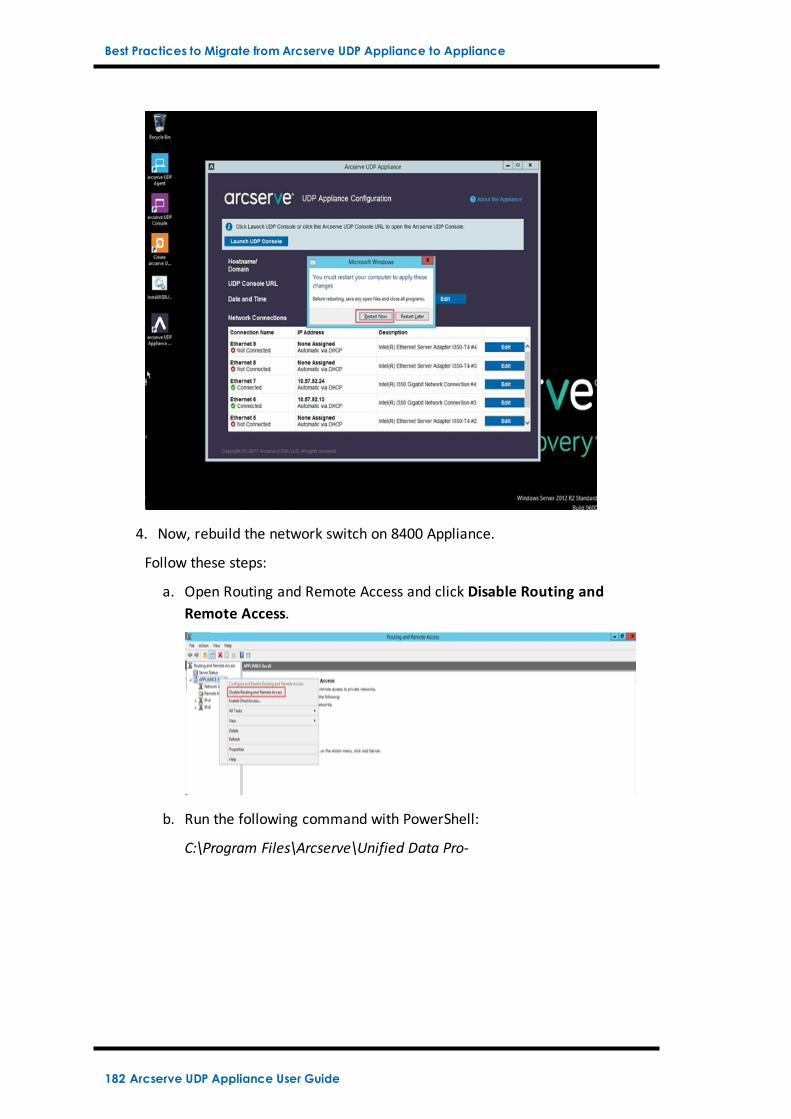
Best Practices to Migrate from Arcserve UDP Appliance to Appliance
4. Now, rebuild the network switch on 8400 Appliance.
Follow these steps:
a. Open Routing and Remote Access and click Disable Routing andRemote Access.
b. Run the following command with PowerShell:
C:\Program Files\Arcserve\Unified Data Pro-
182 Arcserve UDP Appliance User Guide
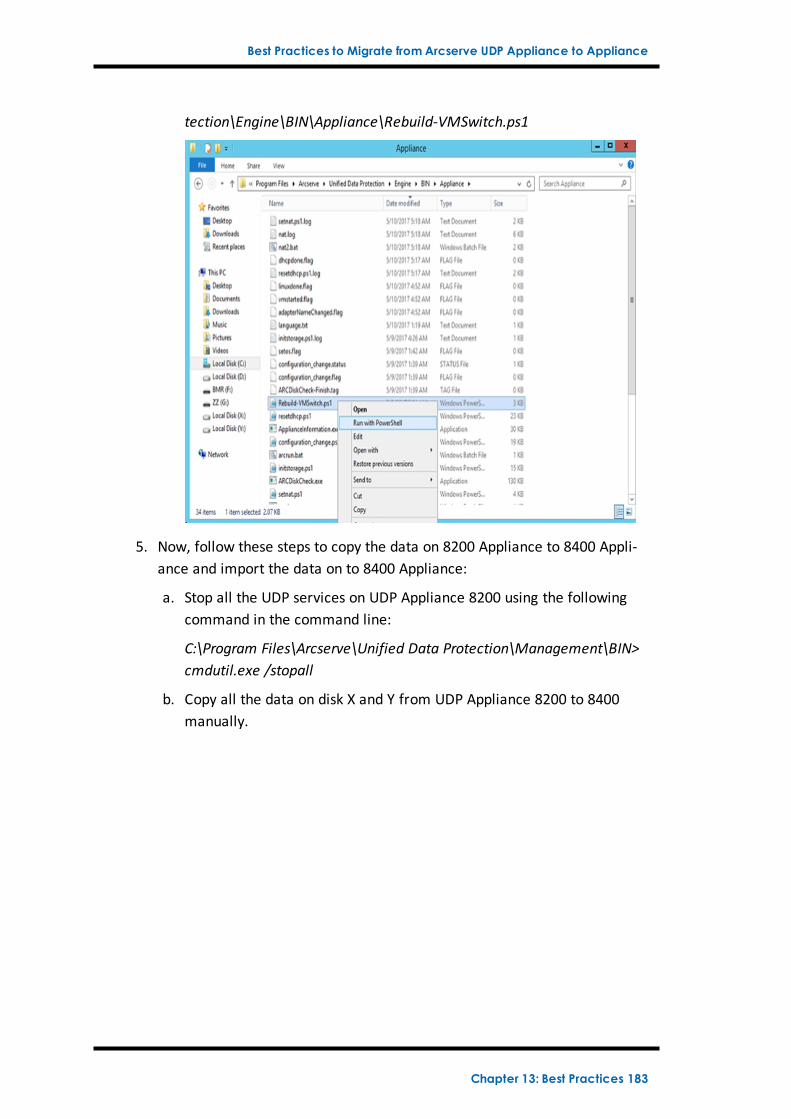
Best Practices to Migrate from Arcserve UDP Appliance to Appliance
tection\Engine\BIN\Appliance\Rebuild-VMSwitch.ps1
5. Now, follow these steps to copy the data on 8200 Appliance to 8400 Appli-ance and import the data on to 8400 Appliance:
a. Stop all the UDP services on UDP Appliance 8200 using the followingcommand in the command line:
C:\Program Files\Arcserve\Unified Data Protection\Management\BIN>cmdutil.exe /stopall
b. Copy all the data on disk X and Y from UDP Appliance 8200 to 8400manually.
Chapter 13: Best Practices 183
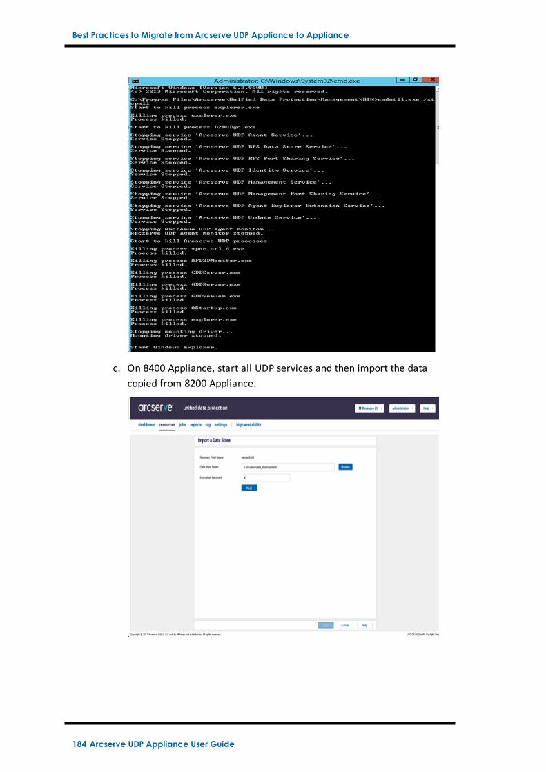
Best Practices to Migrate from Arcserve UDP Appliance to Appliance
c. On 8400 Appliance, start all UDP services and then import the datacopied from 8200 Appliance.
184 Arcserve UDP Appliance User Guide
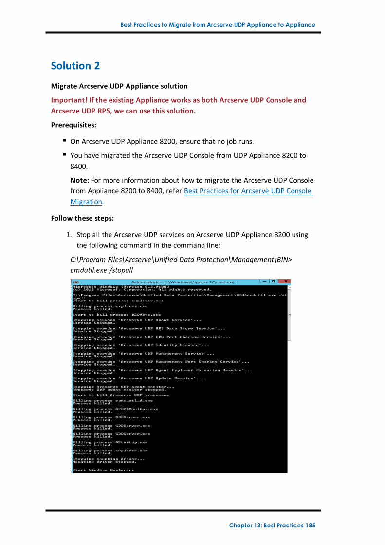
Best Practices to Migrate from Arcserve UDP Appliance to Appliance
Solution 2
Migrate Arcserve UDP Appliance solution
Important! If the existing Appliance works as both Arcserve UDP Console andArcserve UDP RPS, we can use this solution.
Prerequisites:
On Arcserve UDP Appliance 8200, ensure that no job runs.
You have migrated the Arcserve UDP Console from UDP Appliance 8200 to8400.
Note: For more information about how to migrate the Arcserve UDP Consolefrom Appliance 8200 to 8400, refer Best Practices for Arcserve UDP ConsoleMigration.
Follow these steps:
1. Stop all the Arcserve UDP services on Arcserve UDP Appliance 8200 usingthe following command in the command line:
C:\Program Files\Arcserve\Unified Data Protection\Management\BIN>cmdutil.exe /stopall
Chapter 13: Best Practices 185
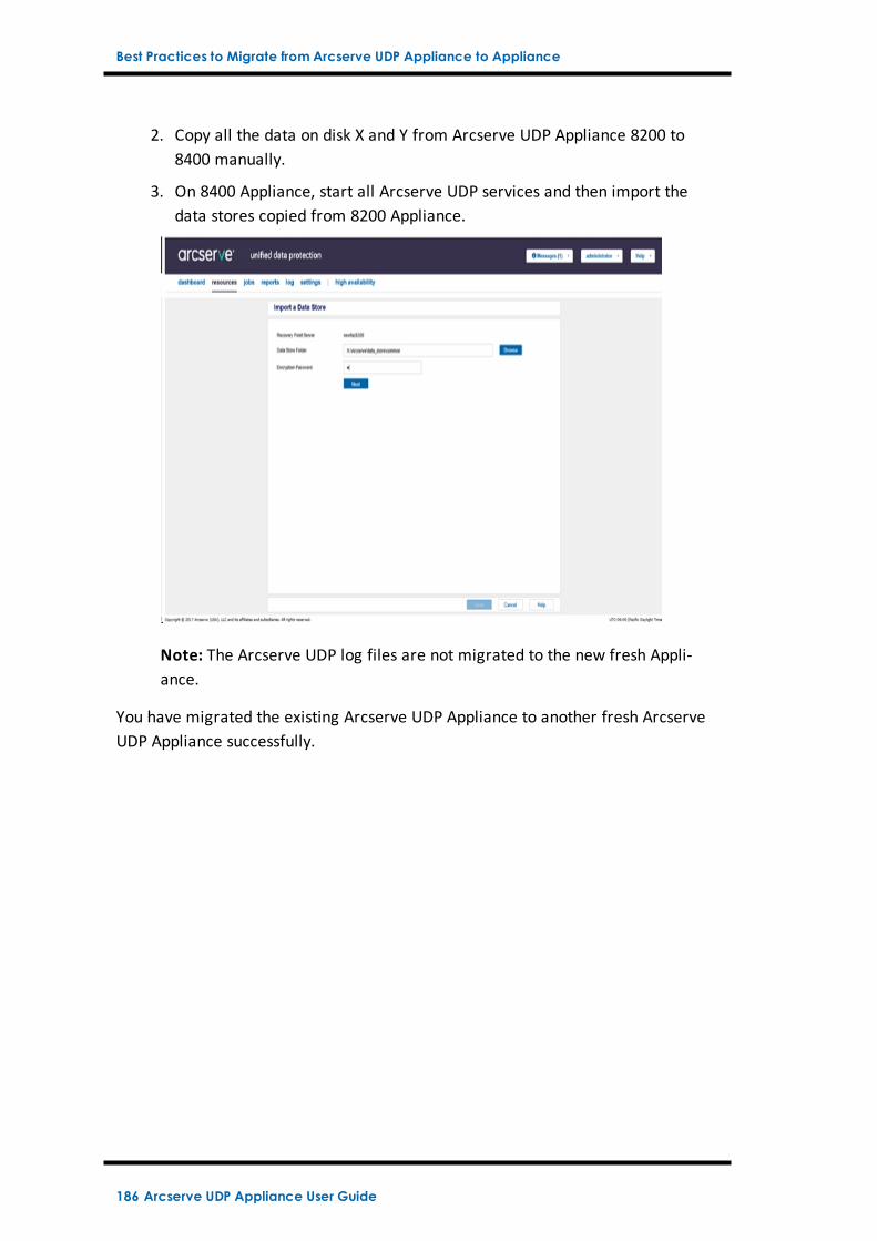
Best Practices to Migrate from Arcserve UDP Appliance to Appliance
2. Copy all the data on disk X and Y from Arcserve UDP Appliance 8200 to8400 manually.
3. On 8400 Appliance, start all Arcserve UDP services and then import thedata stores copied from 8200 Appliance.
Note: The Arcserve UDP log files are not migrated to the new fresh Appli-ance.
You have migrated the existing Arcserve UDP Appliance to another fresh ArcserveUDP Appliance successfully.
186 Arcserve UDP Appliance User Guide
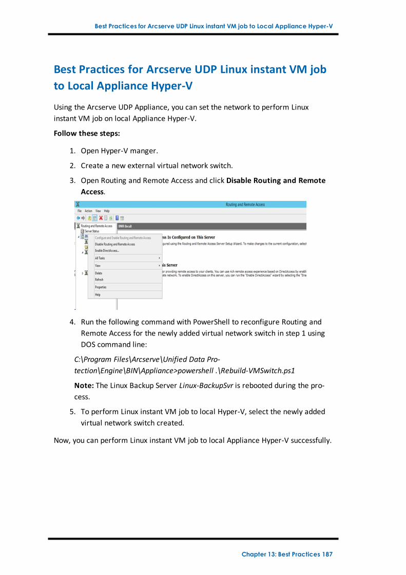
Best Practices for Arcserve UDP Linux instant VM job to Local Appliance Hyper-V
Best Practices for Arcserve UDP Linux instant VM jobto Local Appliance Hyper-V
Using the Arcserve UDP Appliance, you can set the network to perform Linuxinstant VM job on local Appliance Hyper-V.
Follow these steps:
1. Open Hyper-V manger.
2. Create a new external virtual network switch.
3. Open Routing and Remote Access and click Disable Routing and RemoteAccess.
4. Run the following command with PowerShell to reconfigure Routing andRemote Access for the newly added virtual network switch in step 1 usingDOS command line:
C:\Program Files\Arcserve\Unified Data Pro-tection\Engine\BIN\Appliance>powershell .\Rebuild-VMSwitch.ps1
Note: The Linux Backup Server Linux-BackupSvr is rebooted during the pro-cess.
5. To perform Linux instant VM job to local Hyper-V, select the newly addedvirtual network switch created.
Now, you can perform Linux instant VM job to local Appliance Hyper-V successfully.
Chapter 13: Best Practices 187
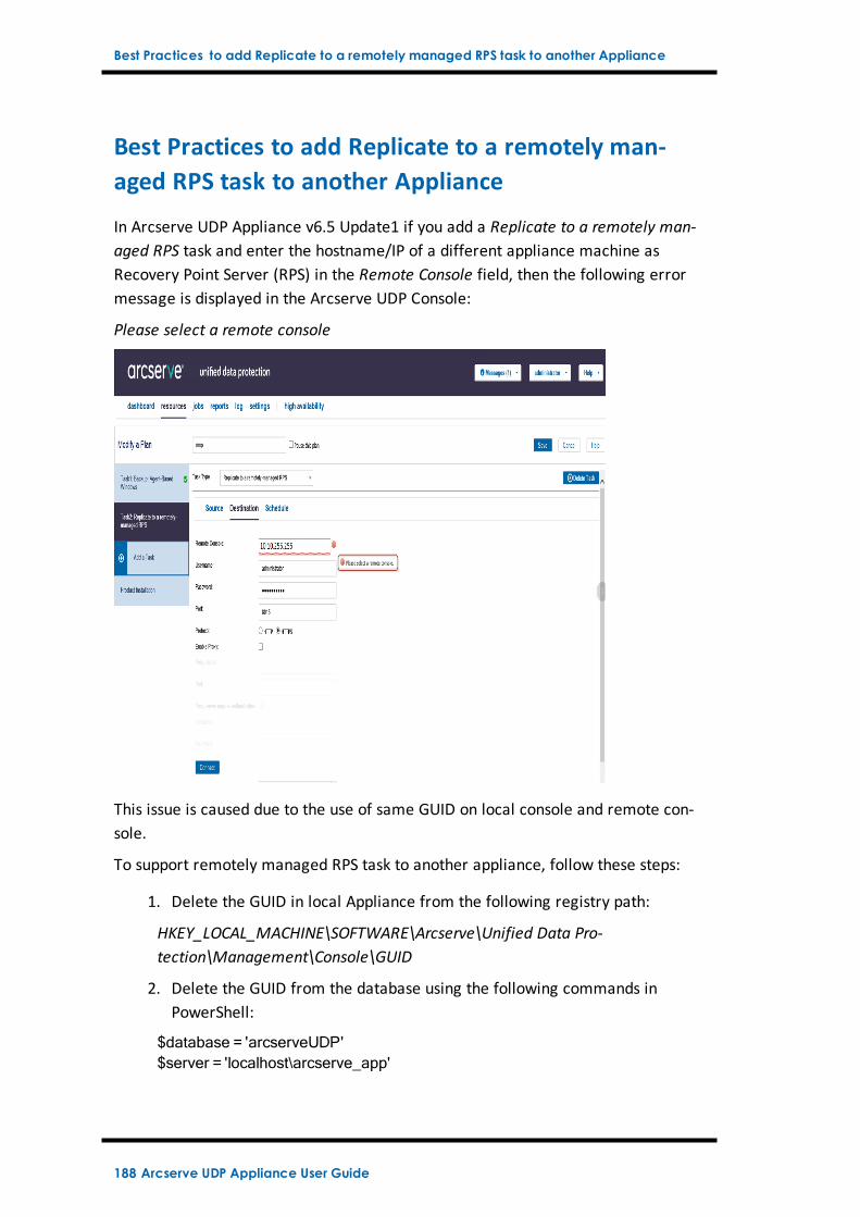
Best Practices to add Replicate to a remotely managed RPS task to another Appliance
Best Practices to add Replicate to a remotely man-aged RPS task to another Appliance
In Arcserve UDP Appliance v6.5 Update1 if you add a Replicate to a remotely man-aged RPS task and enter the hostname/IP of a different appliance machine asRecovery Point Server (RPS) in the Remote Console field, then the following errormessage is displayed in the Arcserve UDP Console:
Please select a remote console
This issue is caused due to the use of same GUID on local console and remote con-sole.
To support remotely managed RPS task to another appliance, follow these steps:
1. Delete the GUID in local Appliance from the following registry path:
HKEY_LOCAL_MACHINE\SOFTWARE\Arcserve\Unified Data Pro-tection\Management\Console\GUID
2. Delete the GUID from the database using the following commands inPowerShell:
$database = 'arcserveUDP'$server = 'localhost\arcserve_app'
188 Arcserve UDP Appliance User Guide
Best Practices to add Replicate to a remotely managed RPS task to another Appliance
$sqlconn =New-Object System.Data.SqlClient.SqlConnection$sqlconn.ConnectionString = "Data Source=$server;Initial Cata-log=$database;Integrated Security=SSPI;"$sqlconn.Open()$sqlcmd =New-Object System.Data.SqlClient.SqlCommand$sqlcmd.Connection = $sqlconn$sqlcmd.CommandText = "delete from as_edge_configuration where Para-mKey='ConsoleUuid'"$sqlcmd.ExecuteNonQuery()$sqlconn.Close()
3. Restart UDP management service on the local appliance machine.
4. From the UDP Console of local machine, follow these steps:
a. Select All nodes in Nodes view.
b. Right click and select Update.
c. Click OK to update all the nodes.
5. Select all RPS nodes in Recovery Point Servers view, right click and selectUpdate to update all RPS nodes.
The Replicate to a remotely managed RPS task is supported successfully betweentwo Appliance machines.
Chapter 13: Best Practices 189
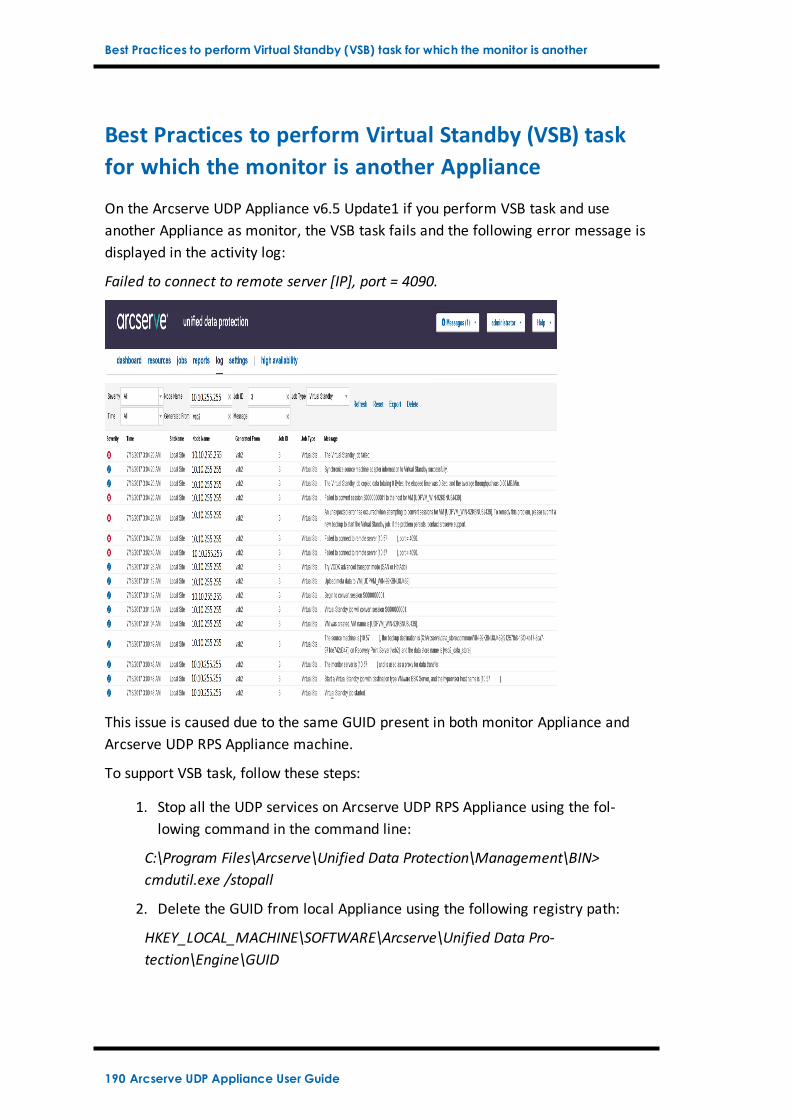
Best Practices to perform Virtual Standby (VSB) task for which the monitor is another
Best Practices to perform Virtual Standby (VSB) taskfor which the monitor is another Appliance
On the Arcserve UDP Appliance v6.5 Update1 if you perform VSB task and useanother Appliance as monitor, the VSB task fails and the following error message isdisplayed in the activity log:
Failed to connect to remote server [IP], port = 4090.
This issue is caused due to the same GUID present in both monitor Appliance andArcserve UDP RPS Appliance machine.
To support VSB task, follow these steps:
1. Stop all the UDP services on Arcserve UDP RPS Appliance using the fol-lowing command in the command line:
C:\Program Files\Arcserve\Unified Data Protection\Management\BIN>cmdutil.exe /stopall
2. Delete the GUID from local Appliance using the following registry path:
HKEY_LOCAL_MACHINE\SOFTWARE\Arcserve\Unified Data Pro-tection\Engine\GUID
190 Arcserve UDP Appliance User Guide
Best Practices to perform Virtual Standby (VSB) task for which the monitor is another
3. Start all the UDP services on Arcserve UDP RPS Appliance using the fol-lowing command in the command line:
C:\Program Files\Arcserve\Unified Data Protection\Management\BIN>cmdutil.exe /startall
4. From the UDP Console of local machine, follow these steps:
a. select All plans in Plans view.
b. Right click and select Deploy Now.
c. Click OK to deploy all plans.
The VSB task is supported successfully.
Chapter 13: Best Practices 191
Chapter 14: AcknowledgementsPortions of this product include software developed by third-party software pro-viders. The following section provides information regarding this third-party soft-ware.
This section contains the following topics:
putty 193
Chapter 14: Acknowledgements 192
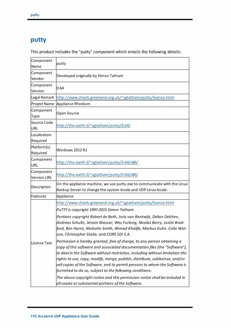
putty
putty
This product includes the "putty" component which entails the following details:
ComponentName
putty
ComponentVendor
Developed originally by Simon Tatham
ComponentVersion
0.64
Legal Remark http://www.chiark.greenend.org.uk/~sgtatham/putty/licence.htmlProject Name Appliance RhodiumComponentType
Open Source
Source CodeURL
http://the.earth.li/~sgtatham/putty/0.64/
LocalizationRequiredPlatform(s)Required
Windows 2012 R2
ComponentURL
http://the.earth.li/~sgtatham/putty/0.64/x86/
ComponentVersion URL
http://the.earth.li/~sgtatham/putty/0.64/x86/
DescriptionOn the appliance machine, we use putty.exe to communicate with the LinuxBackup Server to change the system locale and UDP Linux locale.
Features Appliance
License Text
http://www.chiark.greenend.org.uk/~sgtatham/putty/licence.html
PuTTY is copyright 1997-2015 Simon Tatham.
Portions copyright Robert de Bath, Joris van Rantwijk, Delian Delchev,Andreas Schultz, Jeroen Massar, Wez Furlong, Nicolas Barry, Justin Brad-ford, Ben Harris, Malcolm Smith, Ahmad Khalifa, Markus Kuhn, Colin Wat-son, Christopher Staite, and CORE SDI S.A.
Permission is hereby granted, free of charge, to any person obtaining acopy of this software and associated documentation files (the "Software"),to deal in the Software without restriction, including without limitation therights to use, copy, modify, merge, publish, distribute, sublicense, and/orsell copies of the Software, and to permit persons to whom the Software isfurnished to do so, subject to the following conditions:
The above copyright notice and this permission notice shall be included inall copies or substantial portions of the Software.
193 Arcserve UDP Appliance User Guide
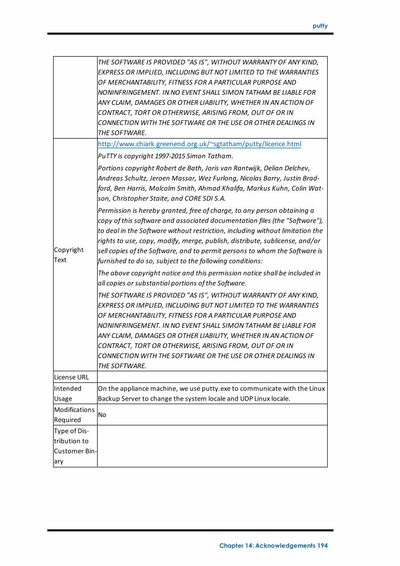
putty
THE SOFTWARE IS PROVIDED "AS IS", WITHOUTWARRANTY OF ANY KIND,EXPRESS OR IMPLIED, INCLUDING BUT NOT LIMITED TO THEWARRANTIESOF MERCHANTABILITY, FITNESS FOR A PARTICULAR PURPOSE ANDNONINFRINGEMENT. IN NO EVENT SHALL SIMON TATHAM BE LIABLE FORANY CLAIM, DAMAGES OR OTHER LIABILITY, WHETHER IN ANACTIONOFCONTRACT, TORT OR OTHERWISE, ARISING FROM, OUT OF OR INCONNECTIONWITH THE SOFTWARE OR THE USE OR OTHER DEALINGS INTHE SOFTWARE.
CopyrightText
http://www.chiark.greenend.org.uk/~sgtatham/putty/licence.html
PuTTY is copyright 1997-2015 Simon Tatham.
Portions copyright Robert de Bath, Joris van Rantwijk, Delian Delchev,Andreas Schultz, Jeroen Massar, Wez Furlong, Nicolas Barry, Justin Brad-ford, Ben Harris, Malcolm Smith, Ahmad Khalifa, Markus Kuhn, Colin Wat-son, Christopher Staite, and CORE SDI S.A.
Permission is hereby granted, free of charge, to any person obtaining acopy of this software and associated documentation files (the "Software"),to deal in the Software without restriction, including without limitation therights to use, copy, modify, merge, publish, distribute, sublicense, and/orsell copies of the Software, and to permit persons to whom the Software isfurnished to do so, subject to the following conditions:
The above copyright notice and this permission notice shall be included inall copies or substantial portions of the Software.
THE SOFTWARE IS PROVIDED "AS IS", WITHOUTWARRANTY OF ANY KIND,EXPRESS OR IMPLIED, INCLUDING BUT NOT LIMITED TO THEWARRANTIESOF MERCHANTABILITY, FITNESS FOR A PARTICULAR PURPOSE ANDNONINFRINGEMENT. IN NO EVENT SHALL SIMON TATHAM BE LIABLE FORANY CLAIM, DAMAGES OR OTHER LIABILITY, WHETHER IN ANACTIONOFCONTRACT, TORT OR OTHERWISE, ARISING FROM, OUT OF OR INCONNECTIONWITH THE SOFTWARE OR THE USE OR OTHER DEALINGS INTHE SOFTWARE.
License URLIntendedUsage
On the appliance machine, we use putty.exe to communicate with the LinuxBackup Server to change the system locale and UDP Linux locale.
ModificationsRequired
No
Type of Dis-tribution toCustomer Bin-ary
Chapter 14: Acknowledgements 194