Embed Size (px)
Citation preview

GDE Appliance
Administration GuideRelease 4.0.0.4
Document Version 110/16/2020

GDE Appliance
Administration GuideRelease 4.0.0.4Administration Guide4.0.0.4Document Version 110/16/2020
All information herein is either public information or is the property of and owned solely by Thales DIS France S.A. and/or its subsidiariesor affiliates who shall have and keep the sole right to file patent applications or any other kind of intellectual property protection inconnection with such information.
Nothing herein shall be construed as implying or granting to you any rights, by license, grant or otherwise, under any intellectual and/orindustrial property rights of or concerning any of Thales DIS France S.A. and any of its subsidiaries and affiliates (collectively referred toherein after as “Thales”) information.
This document can be used for informational, non-commercial, internal and personal use only provided that:
l The copyright notice below, the confidentiality and proprietary legend and this full warning notice appear in all copies.
l This document shall not be posted on any network computer or broadcast in any media and no modification of any part of thisdocument shall be made.
Use for any other purpose is expressly prohibited and may result in severe civil and criminal liabilities.
The information contained in this document is provided "AS IS" without any warranty of any kind. Unless otherwise expressly agreed inwriting, Thales makes no warranty as to the value or accuracy of information contained herein.
The document could include technical inaccuracies or typographical errors. Changes are periodically added to the information herein.Furthermore, Thales reserves the right to make any change or improvement in the specifications data, information, and the like describedherein, at any time.
Thales hereby disclaims all warranties and conditions with regard to the information contained herein, including all impliedwarranties of merchantability, fitness for a particular purpose, title and non-infringement. In no event shall Thales be liable,whether in contract, tort or otherwise, for any indirect, special or consequential damages or any damages whatsoever includingbut not limited to damages resulting from loss of use, data, profits, revenues, or customers, arising out of or in connection with theuse or performance of information contained in this document.
Thales does not and shall not warrant that this product will be resistant to all possible attacks and shall not incur, and disclaims,any liability in this respect. Even if each product is compliant with current security standards in force on the date of their design,security mechanisms' resistance necessarily evolves according to the state of the art in security and notably under theemergence of new attacks. Under no circumstances, shall Thales be held liable for any third party actions and in particular in caseof any successful attack against systems or equipment incorporating Thales products. Thales disclaims any liability with respectto security for direct, indirect, incidental or consequential damages that result from any use of its products. It is further stressedthat independent testing and verification by the person using the product is particularly encouraged, especially in any applicationin which defective, incorrect or insecure functioning could result in damage to persons or property, denial of service or loss ofprivacy.
Copyright 2009 - 2020 Thales Group. All rights reserved. Thales and the Thales logo are trademarks and service marks of Thales and/orits subsidiaries and affiliates and are registered in certain countries. All other trademarks and service marks, whether registered or not inspecific countries, are the properties of their respective owners.

Administration GuideCopyright 2009 - 2020 Thales Group. All rights reserved.
ii
IBM® Guardium Data Encryption
Administration Guide
Release 4.0.0.4
IBMGuardium Data Encryption 4.0.0.4 is the same product as Vormetric Data Security (VDS) Release 6.4.3. VDSRelease 6 consists of Data Security Manager and Vormetric Agents.

Administration GuideCopyright 2009 - 2020 Thales Group. All rights reserved.
iii
Contents
Preface xviiDocumentation Version History xviiAssumptions xviiDocument Conventions xviiTypographical Conventions xviiiNotes, tips, cautions, and warnings xviii
Hardware-RelatedWarnings xixSales and Support xix
Chapter 1: GDE Appliance 20Overview 20Separation of Duties 20Domains 20Administrators 21Administrator Types 21SystemAdministrator 22Domain Administrator 22Security Administrator 22All administrator 23Domain and Security Administrator 23
Read-Only Administrators 24CLI Administrators 24
Chapter 2: Multitenancy 25Overview 25ImplementingMultitenancy 25Creating Local Domain Administrators 26Logging in to a local domain 26Creating a local Security Administrator 26Creating a local Domain or Security Administrator as Read-Only 27
Chapter 3: Creating, Adding, and Deleting Administrators 28Creating Administrators 28Importing Administrators 29Selecting LDAP administrators 30
Deleting Administrators 30To remove an administrator from a domain 31To delete an administrator 31

Administration GuideCopyright 2009 - 2020 Thales Group. All rights reserved.
iv
Resetting Administrator Passwords 31
Chapter 4: Smart Card Access 33Prerequisites 33
Port Configuration 33Setting up and Configuring the Smart Card 33Enabling Smart card usage in the GDE Appliance 33Import Smart Card CA Certificate 34Export Smart Card CA Certificate 34Delete Smart Card Certificate 34Enabling LDAP Users to use a Smart Card 34Enabling GDE Administrators to use a Smart Card 35
Initial Login when using a Smart Card User 35Logging on after Initial Logon 36
Chapter 5: Configuring Preferences and Viewing Logs 38Overview 38Configuring Preferences 38Setting Display preferences 38Setting System preferences 39Setting password preferences 43Password Characteristics 43Password Complexity 44Account Lockout 44
Log Preferences 44Setting Log Preferences 45Server Log Preferences 45Agent Log Preferences 46
Network Diagnostics 48
Chapter 6: Domain Management 50Adding Domains 50Deleting Domains 50Assigning Domains to Domain Administrators 51
Chapter 7: External Certificate Authority 52Overview 52Installing an External Certificate Authority 52Installing an external CA in a high availability system 52

Administration GuideCopyright 2009 - 2020 Thales Group. All rights reserved.
v
Administrative Tasks 53Changing the External CA 53Restoring the GDE Appliance to a self-signed Certificate Authority 53
Intermediate Certificate Authority 53Intermediate CA Info 53Setting up ICA 54
Intermediate Certificate Authority CSR Generation 54PKI infrastructure 55Obtaining an external certificate 55Install Certificates 56Install Certificate Chain 56Importing the Root Certificate and Verifying a Secure Connection 57
Chapter 8: Using an LDAP Server 58LDAP Servers 58Configure LDAP servers 59Importing LDAP Administrators 60Selecting LDAP Administrators 60Configuring LDAP Timeout 61Selecting LDAP users for email notifications 62
Chapter 9: Configuring Syslog Servers for System-Level Messages 64Overview 64Supported Syslog Formats 65Plain Message 66Common Event Format (CEF) log format 66RFC5424 67Log Event Extended Format (LEEF) 68
Adding a Syslog Server 68Using Syslog to Troubleshoot the GDE Appliance and Agents 69Analyzing log entries 69Analyzing VTE Agent log entries 70Logmessage levels 71Using log files 72
VTE Agent Log Files 73vorvmd.log (Windows)/vorvmd_root.log (UNIX) 73messages (UNIX only) 73secfs.log (AIX only) 73secfsd.log 73

Administration GuideCopyright 2009 - 2020 Thales Group. All rights reserved.
vi
statusfile 74GDE Appliance Log Files 74badlog.log 75cgss.log 75jboss.log 75server.log 75
Pruning theGDE Appliance Logs 76Exporting Logs 76Exporting theMessage Log 77Exporting system logs 78Exporting the GDE Appliance system log files 79
Adding an Email Notification Group 79Enabling email notification for logmessages 80Changing the SMTP server and port for email notification 80
Chapter 10: Configuring SNMP 81Overview 81Enabling SNMP on theGDE Appliance 81Adding SNMP Servers 82
ChangingOID Values 84Displaying Vormetric-specific SNMP Information 85Example SNMPQueries 86
Chapter 11: Backing Up and Restoring 88Overview 88Backing Up theGDE Appliance Configuration 88Differences between System-level and Domain-level Backups 89Backup EncryptionWrapper Key 89Create a wrapper key 89
System-level Backup 91Per Domain Backup and Restore 92Domain-level Backup 92
Restoring Backups 92Restoring the GDE Appliance from a backup 93
Automatic Backup 93Schedule an Automatic Backup 93SCP and SFTP 94WindowsShare 94
Schedule an immediate backup 95

Administration GuideCopyright 2009 - 2020 Thales Group. All rights reserved.
vii
Remove schedule and settings 96
Chapter 12: High Availability (HA) 97High Availability Overview 97Synchronization Status on the Dashboard 97High availability synchronization status 98Dashboard Host Assignment 98Display HA configuration status 99
HA Cluster Status 100Server Node HA Status 100Setting up HAmonitoring for Server Node HA Status 101
HA Topology 101Recovering from incomplete node synchronizations 102Assigning VTE Agent Hosts to HA Nodes in an HA cluster 103VTE Agent Availability 103
Best Practices for HA Clusters 103
Chapter 13: Multifactor Authentication with RSA 105Overview 105Configuring RSA Authentication 106Additional RSA configuration notes 106
Chapter 14: Viewing and Downloading System-Level Reports 107Overview 107Viewing and Downloading Reports 107System-Level Reports 107Administrators 107Servers 108Security Domains 108Executive Summary 108
Chapter 15: Domain and Security Administrators 110Overview 110Assigning Domain Administrators or Security Administrators to Domains 110AddGlobal Domain or Security Administrators to a domain 111Add Local Domain or Security Administrators to a restricted domain 111
Security Administrator Roles 113Assigning Security Administrator Roles 114Preventing Security Admins fromDisabling Domain Admins 114

Administration GuideCopyright 2009 - 2020 Thales Group. All rights reserved.
viii
Globally Preventing Disabling Administrators 114Locally Preventing Disabling Administrators 115
Chapter 16: Configuring Syslog Server for Application-Level Messages 116Overview 116Supported Syslog Formats 117Plain Message 117Common Event Format (CEF) log format 118RFC5424 119Log Event Extended Format (LEEF) 119
Adding a Syslog Server 119Using Syslog to Troubleshoot the GDE Appliance and Agents 121Analyzing log entries 121Analyzing VTE Agent log entries 122Logmessage levels 123Using log files 124
VTE Agent Log Files 125vorvmd.log (Windows)/vorvmd_root.log (UNIX) 125messages (UNIX only) 125secfs.log (AIX only) 125secfsd.log 126statusfile 126
GDE Appliance Log Files 126badlog.log 127cgss.log 127server.log 128
Exporting Logs 128Exporting theMessage Log 129
Adding an email Notification Group 130Enabling email notification for logmessages 130
Chapter 17: Viewing and Downloading Domain-Level Reports 131Overview 131Viewing and Downloading Reports 131Domain-Level Reports 131Keys 132Key-Policy 133Policies 133Policy-Key 134

Administration GuideCopyright 2009 - 2020 Thales Group. All rights reserved.
ix
Policy-Host 134Hosts 135GuardPoints 135Host Registration Activities 136Hosts with GuardPoint Status 136Report Tasks 137
Chapter 18: Viewing GDE Appliance Preferences and Logs 140ViewingGDE Appliance Preferences 140Setting Log Preferences 140Server Log Preferences 140Agent Log Preferences 141
Configure Docker Log Settings 143Viewing Logs 145
Chapter 19: Creating and Configuring Signature Sets 146Creating Signature Sets 146Adding files to a set 148
Signing Files in a Signature Set 151Using signature sets in a policy 153Checking the agent logs if signing fails 153
Checking Signing Completion Status 154Stopping Signing 155Re-Signing Files in a Signature Set 155Displaying Signatures, Detecting Duplicate Files 156
Displaying Specific Signed Files in a Signature Set 156Deleting Signatures from a Set 157Deleting Signature Sets 158
Chapter 20: Managing Keys 160Overview 160Protecting Keys 161Agent Keys 161Creating and Adding symmetric keys 162Create a symmetric key 162
Creating Asymmetric keys 165Create an asymmetric key 165
Efficient Storage Encryption Keys 165In-place Data Transformation - Device Encryption Keys 166

Administration GuideCopyright 2009 - 2020 Thales Group. All rights reserved.
x
Versioned Keys 167Storing and Caching Encryption Keys 167Stored on Server keys 167Cached on Host keys 167Cached on Host with Unique to Host 168
Modifying and Displaying KeyConfiguration 168Modify and display key information 169
Delete keys 172Enhanced EncryptionMode 172Encryption Key Protection 173Exporting and Importing Keys 173Importing keys 173Exporting keys 174Exporting a public key 175Export the public key of an RSA key pair 175Importing an Asymmetric public key of an RSA key pair 176
Importing Externally Generated Keys (BYOK) 176BYOK 176Generating a symmetric key file 177Exporting the public key 177Convert the key from hex to binary 177Encrypt symmetric key 177Converting the bytes to base64 178
Importing Symmetric Keys (BYOK) 178KeyGroups 179Add KeyGroup 179Edit KeyGroup 180Delete KeyGroup 180
Key Templates 180Common Key Template Procedures 183Adding a key template 183Deleting a key template 183Modifying a key template 183Using a key template 183Enforcing a key template to define a key 184
Agent Objects 184Identity-Based Key Access 184UsernameRequirements 184Password Requirements 185Add Client Identity 185

Administration GuideCopyright 2009 - 2020 Thales Group. All rights reserved.
xi
Edit Client Identity 185Delete Client Identity 185
Chapter 21: Policies 186Overview 186Policy Rule Criteria and Effects 186Creating and Configuring VTE Policies 187Accessing the Domain to be Protected 187Add a Policy 188Adding a Security Rule Resource Set to a Policy 190Adding a Security Rule User Set to a Policy 193Adding a Security Rule Process Set to a Policy 194Adding a Security Rule Time Set to a Policy 196Adding a Security Rule Action Set to a Policy 198Adding a Security Rule Effect to a Policy 200Default Security Rule 201Add KeySelection Rules 201
Displaying Policies 203Policy History 203Customize display in the Policy window 203
Exporting and Importing Policies 204Export a policy 205Import a policy 205
Chapter 22: Configuring Hosts and Host Groups 207Overview 207Viewing Hosts 207
Adding Hosts to the GDE Appliance 209Adding hosts using a shared secret 209Add a host to a domain using Shared Secret Registration 209Creating and Using a Registration Token 210Register the host on theGDE Appliance 211Create a Registration Shared Secret for a HostGroup 211
Adding hosts using a certificate fingerprint 212Adding hosts using a batch file 214
Configuring Hosts 215Enabling Docker Support 217Enabling Live Data Transformation 218
Setting Host Locks 219

Administration GuideCopyright 2009 - 2020 Thales Group. All rights reserved.
xii
FS Agent locked 221System locked 222Setting locks on Docker hosts 224
Sharing a Host 224Sharing a Local Host with Another Domain 225Shared Host Logging 226
Host Settings 226Host settings for Linux and AIX 227Default settings for Linux 227Default settings for AIX 227
Host settings for Windows 227Default settings for Windows 227
Host settings for a Docker enabled host 228Oracle database in a guarded NFSmount on AIX 228Host setting keywords 229Configuring Application Authentication Credentials 230Re-Sign Settings 230
Agent Log Settings 231FS Agent Log 231Message Type 231Message Destination 232File Logging Settings 232Syslog Settings 232Upload Logging Settings 233DuplicateMessage Suppression Settings 233
Key Agent Log 234Message Type 234Message Destination 234
Docker Log 235Automatic Renewal of Host Certificates 236Certificate renewal notification 236Updating host certificates 236
Modifying Host Configuration 237Changing the VTE Agent host password 239
Deleting Hosts 239Indications that a host has been deleted 240
Deleting a host 240Deleting hosts with System or FS Agent Locks 240Deleting OneWay communication hosts 241
Configuring Host Groups 241

Administration GuideCopyright 2009 - 2020 Thales Group. All rights reserved.
xiii
Creating a host group 241Registering hosts to a host group 241Creating a Registration Shared Secret for a host group 242Adding Hosts to a Host Group using Fingerprint method 242
Creating a cluster host group 243Displaying host groups 244Editing host groups 244Host group passwordmanagement 245Resetting a host group password 245
Protecting a host group 245Protecting a Docker host group 248Apply a Docker GuardPoint 248
Sharing host groups 248Share a host group: 249Remove sharing: 249
Host Group Host Settings 249Configure Host Group Host Settings 250Change Host Group Host Settings inheritance 250
Adding hosts to a host group 251Deleting host groups 252
Chapter 23: Managing GuardPoints 253Overview 253Considerations before creating aGuardPoint 254Changing a policy or rekeying aGuardPoint 255
UnderstandingGuardPoints 255Creating and Applying aGuardPoint 257
LDTQuality of Service 260Creating LDTGuardPoints 261Creating Docker GuardPoints 261Creating IDT Device GuardPoints 263Enabling GuardPoints for Raw DevicesUsing Secure Start 263Creating COS GuardPoints 264Creating CloudObject StorageGuardPoints in a Host Group 265Valid Styles for CloudObject StorageGuardPoints 265Valid Directory Levels for CloudObject StorageGuardPoints 266
Creating GuardPoints on a Host Group 266Create a host groupGuardPoint 266Creating LDTGuardPoints on a host group 267Creating Docker GuardPoints on a host group 267

Administration GuideCopyright 2009 - 2020 Thales Group. All rights reserved.
xiv
Creating CloudObject StorageGuardPoints in a Host Group 267Automatic andManual GuardPoints 268Selecting aGuardPoint mount type 270
Displaying VTE Agent GuardPoint Status 270Viewing VTE Agent GuardPoint status 270Viewing Docker GuardPoint Status 271
ConfiguringWindowsNetwork Drives 272Deleting GuardPoints 273
Chapter 24: Key Management Interoperability Protocol (KMIP) 276Overview 276KMIP Data Sheet 276Requirements 277KMIP Client Registration 278Enable the GDE Appliance for KMIP 278Establish Trust betweenGDE Appliance and KMIP Client 279Create a KMIP-enabled domain 279Backing up a KMIP-enabled domain 279Managing KMIP CA Certificates 279Turn off validation 280Delete a CA certificate 280Export a CA Certificate 280
Managing KMIP Objects 280Viewing KMIP objects 280
KMIP High Availability 281
Chapter 25: Security Administrator Preferences & Logs 282Viewing Preferences 282Viewing Logs 282
Chapter 26: GDE Appliance Command Line Interface 284Overview 284GDE Appliance CLI Navigation 285Network Category Commands 286ip 286ip address 286ip link 288xmithashpolicy 290ip link show 290

Administration GuideCopyright 2009 - 2020 Thales Group. All rights reserved.
xv
ip route 291ip dhcp 292
dns 293DNS Search 294DNS Clear 294DNS1 | DNS2 | DNS3 294DNS OnwithDHCP 294DNS OffwithDHCP 294DNS Switchhosts 294
host 295ssh 296ping 297traceroute 297rping 298arp 298checkport 299nslookup 300
SystemCategory Commands 300setinfo 301setinfo show 301
console 302security 302masterkey 302signcert 303gencert 304genca 305suiteb 307mode 307cc 308boot-passphrase 308legacyregistration 311
mfauth 311tls1 312shutdown 313reboot 313server 313restart 314status 314
Maintenance Category Commands 314config 315

Administration GuideCopyright 2009 - 2020 Thales Group. All rights reserved.
xvi
Retrieving SecurityWorld 316showver 316delver 317ntpdate 317date 319time 319gmttimezone 320diag 321diskusage 321log 321osversion 323uptime 323vmstat 323
repair 324vacuum 324prunewal 324purge policy history 324
High Availability Category Commands 325add 325cleanup 326join 326remove 327show 328
User Category Commands 328add 329delete 330modify 330show 330
Chapter 27: Other Data Center Administrative Roles 332SystemAdministrators 332Data Center Administrators 332Database Administrators 332Network Administrators 332Security Administrators 332Web Administrators 333Storage Administrators 333Computer Operators and Lab Technicians 333

Administration GuideCopyright 2009 - 2020 Thales Group. All rights reserved.
xvii
PrefaceTheAdministration Guide describes how to install and configure the GDE appliance. This document is intended forsystem administrators who install the appliance and connect it to a network.
Documentation Version HistoryThe following table describes the documentation changes made for each document version.
Document Version Date Changes
GDE v3.0 v1 09/22/2017 The GDE 3.0a release is the same as DSM release v6.0.1. This releaseintroduces the following new features: Bonded NICs, a new conciseinitialization method that reduces the load on the appliance and the networkwhen the agents are re-initialized, and re-signing of host settings.Enhancements have been made to Availability.
GDE 3.0b v1 12/14/2017 GDE 3.0b release is the same as DSM release v6.0.2-patch. This releaseaddresses several security issues.
GDE 3.0.0.2 09/07/2018 GA release of GDE 3.0.0.2. The GDE 3.0.0.2 release is the same as DSMrelease v6.1.0. Virtual appliances can now be HMS-enabled by connectingthem to an nShield Connect appliance.
GDE 4.0.0.0 4/11/2019 GA release; HA is now active/active, new CLI commands, new API calls . Thisguide contains new troubleshooting information. Added rules for hostnames.
GDE 4.0.0.1 09/13/2019 Supports Efficient Storage with VTE 6.2.0, Excluding files from encryption,fixed security vulnerabilities.
GDE 4.0.0.1 12/19/2019 DSM is now compatible with Smart cards. System admins can preventdomain admins from deleting other admins, LDAP limits raised.
GDE 4.0.0.3 5/22/2020 Supports IDT (In-place data transformation - device) policies andGuardPoints.Enabled Secure Start for ESG. Added Key Governance forDSM keys, and registration tokens.
GDE 4.0.0.4 10/16/2020 Various GUI improvements. You can now integrate with multiple LDAPforests. Web Certificate supports using SAN.
AssumptionsThis documentation assumes that you have knowledge of your computer network as well as network configurationconcepts.
For more information about what’s new in this release, refer to the Release Notes.
Document ConventionsThe document conventions describe common typographical conventions and important notice and warning formatsused in Thales technical publications.

PrefaceDocument Conventions
Administration GuideCopyright 2009 - 2020 Thales Group. All rights reserved.
xviii
Typographical ConventionsThis section lists the common typographical conventions for Thales technical publications.
Convention Usage Example
bold regular font GUI labels and options. Click the System tab and selectGeneralPreferences.
bold italicmonospaced font
variables or text to be replaced https://<Token Server name>/admin/Enter password: <Password>
regular
monospacedfontCommand and code examplesXML examples
Example:session start iptarget=192.168.253.102
italic regular font GUI dialog box titles The General Preferences window opens.
File names, paths, and directories /usr/bin/
Emphasis Do not resize the page.
New terminology Key Management Interoperability Protocol(KMIP)
Document titles See Administration Guide for informationaboutGDE Appliance.
quotes File extensions Attribute valuesTerms used inspecial senses
“.js”, “.ext”“true” “false”, “0”“1+1” hot standby failover
Table 3-1: Typographical Conventions
Notes, tips, cautions, and warningsNotes, tips, cautions, and warning statements may be used in this document.
A Note provides guidance or a recommendation, emphasizes important information, or provides a reference to relatedinformation. For example:
NoteIt is recommended to keep tokenization keys separate from the other encryption/decryption keys.
A tip is used to highlight information that helps you complete a task more efficiently, such as a best practice or analternatemethod of performing the task.
TipYou can also use Ctrl+C to copy and Ctrl+P to paste.
Caution statements are used to alert you to important information that may help prevent unexpected results or dataloss. For example:
CAUTIONMake a note of this passphrase. If you lose it, the card will be unusable.

PrefaceHardware-Related Warnings
Administration GuideCopyright 2009 - 2020 Thales Group. All rights reserved.
xix
A warning statement alerts you to situations that can be potentially hazardous to you or cause damage to hardware,firmware, software, or data. For example:
WARNINGDo not delete keys without first backing them up. All data that has been encrypted withdeleted keys cannot be restored or accessed once the keys are gone.
Hardware-Related WarningsThe following warning statement is used to indicate the risk of electrostatic discharge of equipment:
ELECTROSTATIC DISCHARGEIf this warning label is affixed to any part of the equipment, it indicates the risk ofelectrostatic damage to the module. To prevent equipment damage, follow suitablegrounding techniques.
The following warning statement is used to indicate the risk of hazardous voltages of equipment:
HAZARDOUS VOLTAGESThe warnings in this section indicate voltages that could cause serious danger topersonnel.
Sales and SupportIf you encounter a problem while installing, registering, or operating this product, please refer to the documentationbefore contacting support. If you cannot resolve the issue, contact your supplier or Thales Customer Support.
Thales Customer Support operates 24 hours a day, 7 days a week. Your level of access to this service is governed bythe support plan arrangements made between Thales and your organization. Please consult this support plan forfurther information about your entitlements, including the hours when telephone support is available to you.
For support and troubleshooting issues:
l https://supportportal.thalesgroup.coml (800) 545-6608
For Thales Sales:
l https://enterprise-encryption.vormetric.com/contact-sales.htmll [email protected] (888) 267-3732

Administration GuideCopyright 2009 - 2020 Thales Group. All rights reserved.
20
Chapter 1: GDE ApplianceOverview 20Separation of Duties 20Domains 20Administrators 21
TheGDE Appliance creates, stores andmanages the policies that protect data. It is available as a virtual appliance.This document describes the work flow needed to set up the GDE Appliance to protect your data. Refer to thecorresponding version of the release notes for information about new features and updates.
OverviewTheGDE Appliance lets you create, store, andmanage policies that protect data residing on host servers (referred toas ‘hosts’ from here on throughout the document, unless otherwise specified). TheGDE Appliance is managed byGDE Appliance administrators who access the GDE Appliance through a browser-based user interface called theManagement Console.
GDE Appliance administrators manage VTE and VAE Agents that reside on host servers and protect the data on thosehosts. GDE Appliance administrators specify data access policies that are sent to these agents. Policies are created,stored andmanaged by GDE Appliance administrators. GDE Appliance administrators specify data access policies,create new administrators and administrative domains, generate usage reports, register new hosts, and accesssecurity logs.
For high availability (HA), GDE Appliances can be configured together in a cluster. The nodes run in parallel in anactive-active format. When one node fails, the other nodes continue to run. When the failed node is back up, itresynchronizes with the other HA nodes. The HA nodes are also used for load balancing the VTE agents.
TheGDE Appliance generates log entries for all configuration changes, system events, access attempts, and filesystem agent communications. These log entries can be sent to standard Syslog servers in several formats.
Separation of DutiesAlthough themain focus of the GDE Appliance is the security of your data through encryption, segregation of data, andpolicy-based access enforcement, a key feature of the GDE Appliance incorporates the critical IT security concept ofseparation of duties with regard to administration of the GDE Appliance and the VTE agents and with the overall datacenter operation. It is this separation of duties that enhances compliance with regulatory requirements.
TheGDE Appliance allows for the creation of domains to separate administrators and the data they access from otheradministrators. A domain is a self-contained environment composed of keys, policies, hosts, administrators, and auditrecords. There are three types of administrators, each with specific roles and permissions. Segmenting administrativefunctions by type ensures that one administrator cannot control the entire data security process.
DomainsA GDE Appliance administrative domain is a logical entity used to separate administrators, and the data they manage,from other administrators. Administrative tasks are done in each domain based upon each administrator’s assignedtype. The benefits of administrative domains are:
l Segregation of data for increased security
l Separation of responsibilities
l No single administrator has complete control over the GDE Appliance and the data it protects

Chapter 1: GDE ApplianceAdministrators
Administration GuideCopyright 2009 - 2020 Thales Group. All rights reserved.
21
Two types of domains can be created; global domains and restricted or local domains.
Global domains are created at the system level and can share GDE Appliance Domain Administrators andGDEAppliance Security Administrators. GDE Appliance global domains enable different business units, application teams,or geographical locations to share the GDE Appliance’s protection without having access to each other’s securityconfiguration.
Restricted or local domains are domains in which administration is restricted to Domain Administrators and SecurityAdministrators assigned to that domain and configuration data in one domain is invisible to administrators in otherdomains. GDE Appliance Domain administrators in restricted domains cannot be assigned tomultiple domains. Oncethe first Domain Administrator is created and assigned to a restricted domain, that Domain Administrator createsadditional Domain Administrators and Security Administrators as required. Domain Administrators created within arestricted domain are not visible outside of that domain, and can only be created and deleted by a DomainAdministrator from that restricted domain.
AdministratorsTheGDE Appliance is administered by aGDE Appliance System Administrator. GDE Appliance SystemAdministrators are different from regular data center system administrators—aGDE Appliance administrator’s primaryresponsibility is to provide data access to those who need it and block data access to those who don't need it,including other GDE Appliance Administrators and data center system administrators.
To enforce separation of duties for strict adherence to good IT security practices and standards, we recommendcreating customized administrator roles for individual users such that no one user has complete access to all data andencryption keys in all domains, see "Separation of Duties" on the previous page for more information.
GDE Appliance administrators protect data by establishing data access policies, encrypting data, and auditing dataaccess attempts.
Administrator TypesThere are three primary types of administrators, each with specific roles and permissions. Segmenting administrativefunctions by type ensures that one administrator cannot control the entire data security process. Each Administrator isallowed to do specific administrative tasks.
TheGDE Appliance provides the following three primary types of administrators:
l System AdministratorsSystem administrators create domains and administrators, and assign a domain’s first administrator.
l Domain AdministratorsA Domain administrator, once assigned to a domain, can assignmore domain administrators and securityadministrators to the domain or remove them from the domain.
l Security AdministratorsA Security administrator, once assigned to a domain (with appropriate roles), canmanage hosts, keys andpolicies in the domain.
However, under a “relaxed security mode”, combined administrator type assignments can also be configured:
l All AdministratorSuch administrators can operate both inside and outside of global domains. When an All administrator enters adomain, that administrator can perform Domain Administrator and Security Administrator tasks. When thisadministrator exits a domain, that administrator can perform System Administrator tasks.
l Domain and Security Administrator

Chapter 1: GDE ApplianceAdministrators
Administration GuideCopyright 2009 - 2020 Thales Group. All rights reserved.
22
A Domain and Security Administrator can do every task that is permitted inside a domain. For example, they canadd administrators to the domains of which they are amember, but they cannot create new administrators.
Additionally, any of these administrators can be created as read-only users. A read-only administrator inherits all of theprivileges of the designated administrator, but without the ability to modify any settings. A read-only administrator canonly view all of the configuration information available to it.
System AdministratorSystem Administrators operate outside of domains. They create domains and assign Domain Administrator to thedomains. They create domains but do not operate within them. Domain and Security Administrators operate withinthose domains created by the System Administrator. The default Administrator, admin, is a System Administrator.This administrator creates additional administrators and domains, and then assigns one or more Domain Administratorto each domain.
Domain AdministratorDomain Administrators operate within domains. They can add additional Domain Administrators and SecurityAdministrators to each domain. There are two types of administrative domains; global domains and restricteddomains. Domain Administrators assigned to a global domain can operate within their assigned domains, but can alsobe assigned tomultiple global domains. Global Domain Administrators who aremembers of multiple global domainscan switch between the domains. Global Domain Administrators who aremembers of multiple global domains mustalways know what domain they are in before performing any tasks. If you log in as a Domain Administrator or aSecurity Administrator, and you notice that the administrator, host, or log data is wrong, you aremost likely in thewrong domain.
Domain Administrators assigned to a restricted domain are restricted to that particular domain—they cannot beassigned tomultiple domains.
The Domain Administrator also adds Security Administrators to a domain and assigns them roles (i.e., Audit, Key,Policy, Host, Challenge & Response, and/or Client Identity) that are applied within that domain.
Security AdministratorAll tasks performed by the Security Administrator occur within domains. Security Administrators assigned to a globaldomain are restricted to their assigned domains, but can be assigned tomultiple domains. Security Administrators thatare assigned tomultiple global domains have only the roles that were assigned when they weremade amember of thatdomain. Meaning, the same administrator can have different roles in different domains.
Security Administrators assigned to a restricted domain are restricted to that particular domain, they cannot beassigned tomultiple domains.
Roles are assigned by Domain Administrators when they assign a Security Administrator to a domain. A briefdescription of the roles is described below.
l AuditAllows the Security Administrator to view log data.
l KeyAllows the Security Administrator to create, edit, and delete local key-pairs, public keys only, and key groups.Can also view log data.
l PolicyAllows the Security Administrator to create, edit, and delete policies. (A policy is a set of rules that specify whocan access which files with what executable during what times. Policies are described inmore detail later.) Canalso view log data.

Chapter 1: GDE ApplianceAdministrators
Administration GuideCopyright 2009 - 2020 Thales Group. All rights reserved.
23
l HostAllows the Security Administrator to configure, modify, and delete hosts and host groups. Can also view log data.TheChallenge & Response role is automatically selected when the Host role is selected.
l Challenge & ResponseAllows a Security Administrator to generate a temporary passphrase to give to a host administrator to decryptdata on the host when there is no connection to the GDE Appliance.
l Client IdentityAllows a Security Administrator to create a client identity profile. A client identity is used to restrict access toencryption keys for VAE/VKM host users. See "Identity-Based Key Access" on page 184 for details about thisfeature.
All administratorAll Administrators can operate inside and outside of domains. To operate inside a domain, All administrators must beassigned to that domain first. When the administrator enters a domain, they can perform Domain Administrator andSecurity Administrator tasks. When an All administrator exits the domain, they can perform System Administratortasks.
Domain and Security AdministratorThe Domain and Security Administrator can perform every task that is permitted for an administrator from inside adomain. For example, the Domain and Security Administrator can add administrators to the domains of which they areamember, but they cannot create new administrators.
The administrator types are outlined in the following table.
Type Permissions
System AdministratorsThis administrator cannot do anysecurity procedures in any domain.
Configure High Availability (HA)Upgrade GDE Appliance softwareBackup and restore GDE ApplianceAdd and delete all administratorsReset passwords for all administratorsAdd and delete all domainsAssign one Domain Administrator to each domainConfigure syslog server for system-level messagesInstall license fileConfigure GDE Appliance preferencesView logs
Domain AdministratorsThis administrator cannot removedomains and cannot do any of thedomain security roles.
Add and remove administrators (Domain, Security, All) to and from domainsBackup and restore GDE ApplianceConfigure Security Administrator roles (Audit, Key, Policy, Host, Challenge &Response, Client Identity)Configure Syslog server for application-level messagesView GDE Appliance preferencesView logs
Table 1-1: Administrator Types

Chapter 1: GDE ApplianceAdministrators
Administration GuideCopyright 2009 - 2020 Thales Group. All rights reserved.
24
Type Permissions
Security AdministratorsDo the data protection work specifiedby their roles. Different roles allowthem to create policies, configurehosts, audit data usage patterns, applyGuardPoints, and do other duties.
Configure signature setsConfigure keys and key groupsConfigure online and offline policiesConfigure hosts and host groupsAssign host passwords (manually or generated)Apply GuardPointsShare a host with another domainExport the GDE Appliance public keyImport symmetric keysView GDE Appliance preferencesView logs
Domain and Security Administrators Domain Administrator and Security Administrators capabilities combined. TheseAdministrators are deleted from the GDE Appliance database upon switchingfrom relaxed to strict domain mode.
All System, Domain, and Security Administrators capabilities combined. AllAdministrators are deleted from the GDE Appliance database upon switchingfrom relaxed to strict domain mode.
Table 1-1: Administrator Types (continued)
NoteThe person who performs the initial setup and configuration using the GDE Appliance CLI can also bethought of as another type of administrator. They are system users or data center system administratorswith UNIX login accounts. Although they access the GDE Appliance through the CLI, for strict securitypractices, they should not have access to theManagement Console. Conversely, the administrators listedabove can access theManagement Console, but should not have access to the CLI.
Read-Only AdministratorsAdministrators can also be created as ‘read-only’. A System Administrator can create other administrator as read-onlyusers—except for Domain administrators that are restricted to a domain. The first administrator of a domainmust haveprivileges to create and administer other users within that domain, therefore a restricted Domain administrator cannotbe created as read-only by a System or All administrator.
A read-only user inherits all of the privileges of the type of administrator and the associated roles being createdhowever, they can only view all of the information available to that user. A read-only administrator does not have theability to modify any settings. Read-only administrators can only change their passwords.
CLI AdministratorsCLI administrators perform tasks related to setting up and operating the GDE Appliance installation—they do notadminister the GDE Appliance from the browser-basedManagement Console. CLI administrators are system userswith login accounts. Meaning, they are entered in /etc/passwd and they have directories under /home. The passwordrequirements for both CLI andManagement Console administrators are set by the password policy in theManagementConsole.

Administration GuideCopyright 2009 - 2020 Thales Group. All rights reserved.
25
Chapter 2: MultitenancyOverview 25ImplementingMultitenancy 25
Multitenancy enables the creation of multiple restricted or local domainswithin a single GDE Appliance. A restrictedor local domain is a GDE Appliance domain in which GDE Appliance administration is restricted to DomainAdministrators or Security Administrators assigned to that domain. Multitenancy is particularly useful for CloudService Providers.
OverviewWithmultitenancy, the GDE Appliance platform supports the creation of restricted domains. Restricted or localdomains are different from global domains in that Domain Administrators not assigned to that local domain, cannotmodify or administer that domain in any way. Unlike global domains, local domain administrator accounts cannot beassigned to any other domains. GDE Appliance administration tasks are restricted to local Domain Administrators orlocal Security Administrators within that domain.
TheGDE Appliance System administrator creates the first Domain administrator for a restricted domain, allsubsequent administrators are created by the Domain administrator of that restricted domain. All other administrativetasks within a restricted domain are done by the local Domain administrator of that domain.
Table 2-1: "Differences between global and local domains" below lists some differences between the two types ofdomains/administrators.
Global Domains and Administrators Local Domains and Administrators
Administrator names must be unique within allglobal domains.Domain and Security Administrators can beassigned to multiple global domainsGDE Appliance System Administrators can:Create and assign the first global DomainAdministrator to a global domain. That sameglobal administrator can be assigned to otherglobal domains as well. After that the GDEAppliance System Administrators do no taskswithin global domains.Change the password of any globaladministratorDelete any global administrator.Add or delete a global domain.Disable all administrators in a global domain.
Administrator names must be unique within a localdomain, but can be identical if they are in different localdomains.Local Domain and Security Administrators can onlyfunction within their local domain.GDE Appliance System Administrators:Create the first local Domain Administrator for arestricted or local domain. After that the GDE ApplianceSystem Administrators do no tasks within localdomains.Cannot change the password of a local administratorCannot delete local administratorsCannot access log files in a local domain.Can add or delete local domains.Can disable all administrators in a local domain.
Table 2-1: Differences between global and local domains
Implementing MultitenancyTo create a local domain, the GDE Appliance System Administrator creates a single Domain Administrator for adomain. After that, complete control of the domain is maintained by that domain’s Domain Administrator and anyDomain or Security Administrators created by that Domain Administrator.
Administrators in a local domain doGDE Appliance duties in exactly the sameway as in global domains. The onlydifferences are as follows:

Chapter 2: MultitenancyImplementing Multitenancy
Administration GuideCopyright 2009 - 2020 Thales Group. All rights reserved.
26
l They are restricted to doing GDE Appliance work only in their own local domain
l Administrators not in their local domain (including GDE Appliance System Administrators) cannot do any domain-related work.
NoteWhile GDE Appliance System Administrators cannot view the administrators in the local domain, GDEAppliance System Administrators can disable all administrators in a local domain.
The Domain Administrator of a local domain can also create ‘read-only’ administrators. A read-only user inherits all theprivileges of the administrator type (and the associated roles in the case of Security administrators), being created.See "Read-Only Administrators" on page 24 for more information about Read-Only administrators.
Creating Local Domain AdministratorsThis section describes how to create a local domain and its local Domain Administrator.
1. Log on to theManagement Console as aGDE Appliance System Administrator.
2. Create a domain:a. Exit the current domain if necessary.b. Go toDomains > Manage Domains > Add. Enter domain name (example: Domain-2) and click Ok.
3. Create a Domain Administrator for this domain.a. Go toAdministrators > All > Add.b. Enter Login andPassword.c. ForUser Type select Domain Administrator.d. Restrict to Domain field displays. Select the domain to restrict in the pull-down. Click Ok.
You have now created a local domain (Domain-2) and a local Administrator (Admin2). When you return to theAdministrators window, you will not see the administrator’s name listed in the table. The new administrator is in a localdomain, and does not appear in the list of global administrators.
Logging in to a local domain1. Go to the log in screen of theManagement Console.
2. Enter the login and password of the local Domain or Security Administrator.
3. Check the I am a local domain administrator checkbox and enter the domain name.
4. Click Ok. The Dashboard displays the administrator and the current domain on the top right of the console.
Creating a local Security AdministratorLike a global Domain Administrator, the local Domain Administrator cannot do any of the standard security roles(Audit, Key, Policy, Host, Challenge & Response, and/or Client Identity) unless the administrator has been created asa Domain and Security Administrator. If the Domain administrator is a separate role, the local Domain Administratormust create local Security Administrators to do tasks associated with the different security roles.
NoteGDE Appliance System Administrators cannot create GDE Appliance Security Administrators for arestricted domain.
1. Go to the log in screen of theManagement Console and log in as a local Domain Administrator.

Chapter 2: MultitenancyImplementing Multitenancy
Administration GuideCopyright 2009 - 2020 Thales Group. All rights reserved.
27
2. Click Administrators > Manage Administrators > New.
3. In theAdd Administratorwindow, enter a login and password. Select User Type as Security Administrator.
4. Select the Roles for this administrator account and click Ok.
5. A new local Security Administrator is created.
Creating a local Domain or Security Administrator as Read-Only1. Go to the log in screen of theManagement Console and log in as a local Domain Administrator.
2. Click Administrators > Manage Administrators > New.
3. In theAdd Administratorwindow, enter a login and password.
4. Select aUser Type from the drop down list.
5. Select theRead-Only User check box to create an administrator with read-only privileges. An administrator withread-only access will not be able to add, delete, or modify any settings in the domain. Read-only administratorswill only be able to change their passwords and view the different settings per their type and the roles assigned tothem.

Administration GuideCopyright 2009 - 2020 Thales Group. All rights reserved.
28
Chapter 3: Creating, Adding, and Deleting AdministratorsCreating Administrators 28Importing Administrators 29Deleting Administrators 30Resetting Administrator Passwords 31
A default System Administrator, called admin, already exists on the GDE Appliance. The first time you log on, you doso using the default administrator credentials. Additional administrators must be created to do tasks that a Systemadministrator cannot perform.
Creating AdministratorsThales recommends that you create backup administrators for each administrator type, as a precaution. This way, if aparticular administrator is compromised, that administrator can be deleted and their administrative tasks can beassumed by a different administrator.
1. Log on to theManagement Console as a System/All Administrator.If this is the first time you are logging in, youmust log in with the credentials of the default administrator admin;with the default password admin123. You will be redirected to the reset password page. Youmust reset thepassword. This is true for any administrator logging in for the first time. Note that you cannot delete the defaultadministrator.
2. After resetting your password, theManagement Console Dashboard displays. Click Administrators on themainmenu bar.TheAdministratorswindow opens listing all of the administrators for this GDE Appliance.
3. Click Add. The Add Administrator window displays.
4. In the Add Administrator window, enter the following information:o LoginType a name. Only one instance of an administrator name is allowed.
o Description (Optional)Enter a phrase or string that helps you to identify the administrator. Themaximum number of characters is256.
o RSA User ID (Optional)Required:n RSA AuthenticationManager software application deploymentn RSA SecurID deviceThe RSA SecurID device and RSA user name are bound together in the RSA AuthenticationManagersoftware application by a security administrator. Enter the RSA user name that was configured by thesecurity administrator in the RSA user name text-entry box. The value entered is displayed in the RSA UserName column of the Administrator window.
o PasswordEnter a password. The passwordmust conform to the attributes defined in the password preferences. Themaximum password length is 256 characters.If you have enabled and configuredmulti-factor authentication, an administrator may have two passwords tolog on to theManagement Console: one for a GDE Appliance administrator and one for an RSA user.

Chapter 3: Creating, Adding, and Deleting AdministratorsImporting Administrators
Administration GuideCopyright 2009 - 2020 Thales Group. All rights reserved.
29
TheGDE Appliance administrator password is used to log on to theManagement Console, if multi-factorauthentication is disabled or not configured. Whenmulti-factor authentication is enabled and the administratoris configured for multi-factor authentication, the GDE Appliance administrator logs into theManagementConsole with the RSA SecurID password and the Token Code displayed on the RSA SecurID device.
NoteThe first time an administrator logs on to theManagement Console with a newly created GDE ApplianceAdministrator account, they are prompted to change the password. Administrators cannot reuse the samepassword to create the account.
l Confirm PasswordRetype the password.
l User TypeSelect a type of Administrator from the drop-downmenu:
o System Administratoro Domain Administratoro Security Administratoro Domain and Security Administratoro All
NoteIf you enabled Separation of Duties in theSystem > General Preferences > System tab, then theDomain and Security Administrator andAll options are not available.
l Read-Only UserSelect this option to create an administrator with read-only privileges. You can assign read-only privileges toany type of administrator—except for Local Domain administrators that are the first administrators to beassigned to a domain. If the first administrator added to a local domain is read-only, that administrator will notbe able to create any more administrators for that domain.An administrator with read-only access will not be able to add, delete, or modify any settings on theGDEAppliance. Read-only administrators will only be able to change their passwords and view the differentsettings per their type and the roles assigned to them.
l Smart Card Login EnabledRequires user to use a PIV (Personal Identity Verification) smart card for multifactor authentication. SeeChapter 4: "Smart Card Access" on page 33 for more information.
5. Click Ok. A new Administrator is created. The Administrators page displays a table with the name and type of thenew administrator.
Importing AdministratorsThe Import function imports data from an LDAP server such as Active Directory (AD). Once an LDAP server hasbeen identified and configured, the administrator can import the desired values. See Chapter 8: "Using an LDAPServer" on page 58 for more about configuring an LDAP server.
You need the LDAP login ID and password to import values from an LDAP directory.
1. Select Administrators > All. Click Import.

Chapter 3: Creating, Adding, and Deleting AdministratorsDeleting Administrators
Administration GuideCopyright 2009 - 2020 Thales Group. All rights reserved.
30
2. Enter the Login ID and Password on theConnect to AD/LDAP Server Details page. If the login and passwordwere entered under LDAP Server Settings on theSystem > LDAP page, these values will be populated bythose values and do not need to be re-entered. Youmay also enter a different login and password in place ofthese stored values when you import administrators.
3. Click Connect. The LDAP Users window displays LDAP user names.
4. Search options:a. Use the LDAP Query field to filter searches using the LDAP query language. Results depend on how the
LDAP service is set up. See RFC2307 for full details on syntax.b. Select a Group from theGroup drop down list.c. Enter a User name in theUser field.d. TheMaximum number of entries to return field lets you limit themaximum number of records to import or
display. The default value is 300. Theminimum value is 1 and themaximum value is 1million. A high integervaluemay result in a delay depending on the database size.
5. Click Go.
Selecting LDAP administratorsTheManagement Console provides aGUI interface to themapped LDAP directory values such as login and userdescription. As an Administrator logged into the LDAP directory, you can provide input to the following fields in order toselect andmanage LDAP users. See Chapter 8: "Using an LDAP Server" on page 58 for more information aboutadding LDAP users.
l Group Object ClassSelect a value from the drop downmenu to filter by group type.
l User Object ClassEnter a value or partial value to filter on specific users. Entering a partial value acts as a “wild-card” returning allvalues matching what was entered.
l GoClick to refresh the screen.
l Select AllClick to select all values on this page.
l ViewSelect a value from this dropdown box to control how many values appear on any page.
l SelectedClick to select individual values.
l User TypeSelect a value from this dropdown box to define the type of Administrator or role of the values you import.
l Add/CancelSelect to add or cancel your selections.
Deleting AdministratorsSystem or All administrators can delete other administrators, except for the default admin administrator andthemselves.

Chapter 3: Creating, Adding, and Deleting AdministratorsResetting Administrator Passwords
Administration GuideCopyright 2009 - 2020 Thales Group. All rights reserved.
31
If the administrators to be deleted aremembers of a domain, they must first be removed from that domain (even if thedomain has been deleted), before they can be deleted.
To remove an administrator from a domain1. Log in as a Domain Administrator, Domain and Security Administrator, or All.
2. Remove the administrator you want to delete from every domain from which they are amember.
To delete an administrator1. Log in as an All/System Administrator.
2. Select Administrators > All.
3. In the Administrators window, enable theSelected check box of the administrator(s) to be deleted.
4. Click Delete.
5. You are prompted to verify that you want to proceed with this operation.
6. Click Ok. The selected administrators are deleted from theManagement Console and cannot access the GDEAppliance.
Resetting Administrator PasswordsAdministrator passwords cannot be viewed. If an administrator forgets their password, the System Administrator canassign a new temporary password. The Administrator informs the administrator about their new temporary password.The next time the administrator logs on, they are directed to enter a new password.
If a GDE Appliance administrator is currently running an activeManagement Console session when the SystemAdministrator changes their password, theManagement Console session is immediately terminated and theadministrator must log on again.
When a System Administrator changes the password for a Domain Administrator, Security Administrator, or All, theiraccount is disabled in every domain of which they are amember. They must be enabled by a different DomainAdministrator, Domain and Security Administrator, or All before they can again enter a domain. A disabledadministrator can log on to the GDE Appliance, but the domain selection radio buttons are opaque and cannot beselected, so the administrator cannot enter any domain and cannot modify the GDE Appliance configuration.
The Domain Administrator, Security Administrator, or All account must be enabled in every domain of which they are amember at the time the password is changed. Enabling an administrator in one domain does not enable them for all thedomains of which they are amember.
To change another administrator’s password:
1. Log in as aSystem Administrator orAll.
2. Check that the administrator is not currently logged into theManagement Console because their login sessionbecomes inactive when the password changes.o If you are changing the password of another System Administrator, you can check the log.o If you are changing the password of a Domain Administrator or Security Administrator, have a DomainAdministrator switch to each domain in which the administrator is amember and check the log of eachdomain.
3. Select Administrators > All. The Administrators window opens.
4. Select an administrator in the Login column. The Edit Administrator window opens.

Chapter 3: Creating, Adding, and Deleting AdministratorsResetting Administrator Passwords
Administration GuideCopyright 2009 - 2020 Thales Group. All rights reserved.
32
5. Enter the password and then click Ok.
6. For Domain Administrator, Security Administrator, or All, have a different Domain Administrator, Domain andSecurity Administrator, or All re-enable that administrator’s domains.

Administration GuideCopyright 2009 - 2020 Thales Group. All rights reserved.
33
Chapter 4: Smart Card AccessPrerequisites 33Setting up and Configuring the Smart Card 33Initial Login when using a Smart Card User 35
Multifactor authentication adds additional access control to the GDE ApplianceManagement Console by requiringGDE Appliance administrators to use a smart card each time the administrator logs into theManagement Console.
PrerequisitesMultifactor authentication with a smart card requires the following to be set up prior to use with the GDE Appliance:
l The smart card administrator must provision the smart card according to the smart card instructions.
l Install a mini-port driver for the smart card (mini-port driver is provided by either the smart card vendor orMicrosoft).
l Program the smart card with a PIN number.
NoteThis feature was tested with a Gemalto IDPrimeMD smart card.
Port ConfigurationOpen the following ports for smart card communication:
l RSA with smart card login: 8449
l EC with smart card login: 8450
l Compatible with smart card login: 8450
Refer to thePorts to Configure table in ‘Appendix D’ of theDSM Installation and ConfigurationGuide.
Setting up and Configuring the Smart CardOnce the smart card is provisioned and the administrator has the certificate chain, an administrator can setup thesmart card on the GDE Appliance.
NoteCurrently, Smart Cards are compatible with Internet Explorer v11 andMicrosoft Edge v10.
Enabling Smart card usage in the GDE Appliance1. Click System > General Preferences > System.
2. Go to Smart Card Login and select Smart Card Login Enabled.
3. Click Apply. Smart Card CA certificates now displays in the Systemmenu.

Chapter 4: Smart Card AccessSetting up and Configuring the Smart Card
Administration GuideCopyright 2009 - 2020 Thales Group. All rights reserved.
34
Import Smart Card CA CertificateAn administrator must import a CA certificate into the GDE Appliance.
1. Click System > Smart Card CA certificates.
2. Click Browse and select theCA certificate file.
3. Click Import Certificate.
NoteIf you need to import more than one CA certificate, youmust import the root CA certificate first, followedby the intermediate CA certificate that is signed by the root CA.
4. Click OK when the warning dialog opens.
5. Restart all nodes in the GDE cluster through the CLI (0001:system$ server restart) after all of the CAcertificates have been imported and all of the changes have been replicated successfully to all the other nodes inthe cluster.
Export Smart Card CA Certificate1. Click System > Smart Card CA certificates.
2. Select the certificate to export.
3. Click Export CA Certificate.
4. In the browser question bar, select Save As to export the file to your system.
Delete Smart Card CertificateTo delete a CA certificate:
1. Click System > Smart Card CA certificates.
2. Select the certificate to export.
3. Click Delete.
4. Restart the browser to refresh the new certificate list.
Enabling LDAP Users to use a Smart CardYou can import Administrators from an LDAP server (System > LDAP) and then enable them for smart card accesslike any other GDE Administrator. To be successful, youmust do the following:
l In the AD/LDAP page, youmust enter a Login name and Password.
l Do not delete the contents of the Login name and Password field.
l Do not click Clear to clear any LDAP server settings.
l In the GDE Appliance, in the (Administrators > Import) Connect to AD/LDAP Server page, the Login /Passwordfields are automatically populated from the LDAP Server settings page. Do not change the contents of thosefields.
NoteIf you clear any of the settings, the user will not be able to login because theGDE Appliance will not beable to bind the user with the LDAP server.

Chapter 4: Smart Card AccessInitial Login when using a Smart Card User
Administration GuideCopyright 2009 - 2020 Thales Group. All rights reserved.
35
Enabling GDE Administrators to use a Smart CardA GDE Administrator must enable the smart card feature for other administrators and select the user mapping criteriafor the certificate.
To enable an Administrator to use a smart card:
1. In the Edit/Add Administrator window, select Smart Card Login Enabled.The smart card user mapping criteria list opens. These criteria are used tomap a certificate to this user. Youmust select at least one.
2. Select appropriate criteria for the smart card administrator:
Name Description
Subject CN The Common Name part of the Subject DN
Subject DN Subject Distinguished Name of the smart carduser certificate
Issuer DN Issuer Distinguished Name of the smart card usercertificate
Serial Number Serial Number of the smart card user certificate
Subject Key Identifier Subject Key Identifier of the smart card usercertificate
Public Key Hash The SHA-384 hash of the public key of the smartcard user certificate
User Principal Name Used by Microsoft to identify a user in a Windowsdomain. It is stored in the otherName field of theSubject Alternative Name extension using OID1.3.6.1.4.1.311.20.2.3
RFC822 Name The rfc822 Name field of the Subject AlternativeName extension, this is usually the emailaddress of the user
Table 4-1: Smart Card Options
3. Click OK.
Initial Login when using a Smart Card UserWhen an administrator logs in for the first time with smart card login privileges enabled, they will log in as follows:
1. In the user access dialog, enter your admin name and password.
2. Click OK. The Upload client certificate dialog opens.

Chapter 4: Smart Card AccessInitial Login when using a Smart Card User
Administration GuideCopyright 2009 - 2020 Thales Group. All rights reserved.
36
3. Click Choose File and select the user certificate from the certificate chainThis is the certificate that was imported into the smart card during the smart card provisioning.
4. Click OK to load the user certificate for the administrator.o The certificate file is located on the file system where the web browser runs. It may contain multiplecertificates.
5. After you successfully upload the certificate, plug in the smart card reader, insert the smart card into the reader,and restart the web browser.
6. Enter your login name and password in the GDE Login dialog. Click Login.
7. The confirm certificate dialog opens. Select the certificate that was uploaded to the GDE in a previous step andpress OK.
8. Enter the smart card PIN number.
9. Confirm the certificate again, if required.
Logging on after Initial LogonAfter the administrator is set up on theGDE Appliance and with the smart card, logging in becomes much simpler.When you start the browser with the smart card reader already plugged in and containing a smart card, theWindowsSecurity Confirm Certificate dialog opens.
1. Click Login on the Smart Card Login dialog.
2. Select an appropriate certificate and click OK.
3. Enter the Smart card PIN in the Smart Card Provider dialog and click OK.

Chapter 4: Smart Card AccessInitial Login when using a Smart Card User
Administration GuideCopyright 2009 - 2020 Thales Group. All rights reserved.
37
NoteIf your system is idle for more than aminute, the browser prompts you for the PIN.

Administration GuideCopyright 2009 - 2020 Thales Group. All rights reserved.
38
Chapter 5: Configuring Preferences and Viewing LogsOverview 38Configuring Preferences 38Log Preferences 44Network Diagnostics 48
As aGDE Appliance System Administrator (or type All), you can set many preferences in theManagement Console.
OverviewIn theSystem > General Preferences page, you can set the following preferences:
l DisplayThe number of GDE Appliance objects displayed based on the object type. For example, you can set apreference that displays all configured policies on oneWeb page, rather than just 20 per page.
l SystemEnable Syslogmessaging, enable super administrators, and shorten the update interval when pushing changesto the same policy to hosts on different servers.
l PasswordHow long a passwordmust be, the types of characters that a passwordmust contain, and password duration.Password preferences can also configure the GDE Appliance response to repeated failed login attempts.
In theSystem > Log Preferences page, you can set the following:l Server preferences
Logmaintenance parameters on the GDE Appliance. For example, you can set the interval to wait beforemovingagent log entries from temporary buffers on the GDE Appliance to the GDE Appliance log database, andconsequently to the log viewer.
l VTE Agent logHow theGDE Appliancemaintains agent-specific log data. For example, you can set the interval at which theagent uploads log data to the GDE Appliance.
Configuring PreferencesTheGeneral Preferences tab lets you specify display settings, system settings, password settings, and lets youconfigure the login banner message on the log in screen.
Setting Display preferencesDisplay preferences are administrator-configurable parameters that control the number of objects to display and settheManagement Console expiration time.
To set GDE Appliance display preferences:
1. Log on to theManagement Console as a System/All administrator.
2. Select System > General Preferences in themenu bar.TheGeneral Preference window opens to the Display tab.
3. Change the values displayed in the attribute text-entry boxes or scroll-list.

Chapter 5: Configuring Preferences and Viewing LogsConfiguring Preferences
Administration GuideCopyright 2009 - 2020 Thales Group. All rights reserved.
39
The following table lists and describes attributes and their values.
Category Parameter Description
Domain PageSettings
Number ofDomains Per Page
Sets the maximum number of administrators in the Domainswindow to display on one page. Navigation buttons aredisplayed in the Domains window to move between the pages.The default is 20.
AdministratorPage Settings
Number ofAdministrators PerPage
Sets the maximum number of administrators in the Administratorswindow to display on one page. Navigation buttons aredisplayed in the Administrators window to move between thepages. The default is 20.
Host PageSettings
Number of HostsPer Page
Sets the maximum number of hosts in the Hosts window todisplay on one page. Navigation buttons are displayed in theHosts window to move between the pages. The default is 20.
Number of HostGroups Per Page
Sets the maximum number of host groups in the Host Groupswindow to display on one page. Navigation buttons aredisplayed in the Host Groups window to move between thepages. The default is 20.
Policy PageSettings
Number of PoliciesPer Page
Sets the maximum number of policies in the Policies window todisplay on one page. Navigation buttons are displayed in thePolicies window to move between the pages. The default is 20.
Key/CertificatePage Settings
Number of KeysPer Page
Sets the maximum number of keys in the Keys window to displayon one page. Navigation buttons are displayed in the Keyswindow to move between the pages. The default is 20.
Number of KeyGroups Per Page
Sets the maximum number of key groups in the Key Groupswindow to display on one page. Navigation buttons aredisplayed in the Key Groups window to move between thepages. The default is 200.
Signature PageSettings
Number ofSignature Sets PerPage
Sets the maximum number of signature sets to display on onepage. Navigation buttons are displayed in the Signature Setswindow to move between the pages. The default is 20.
Log PageSettings
Number of LogMessages PerPage
Sets the maximum number of log entries to display on one page.Navigation buttons are displayed in the Logs window to movebetween the pages. The default is 20.
ManagementConsoleTimeout
ManagementConsole Timeout
Sets the interval of inactivity allowed before automaticallylogging administrators out of the Management Console Websession. Unsaved changes are discarded. Choices are 5minutes, 20minutes, 1 hour, 2 hours, and 8 hours. The default is1 hour.
Table 5-1: General Preferences Display tab attributes and their values
4. Click Apply to set the changes.
Setting System preferencesYou can configure attributes that:

Chapter 5: Configuring Preferences and Viewing LogsConfiguring Preferences
Administration GuideCopyright 2009 - 2020 Thales Group. All rights reserved.
40
l Enable or disable all Administrator accounts for Domain and Security administrators. By enabling theSeparationof Duties option, all Domain and Security Administrator accounts are deleted from the database, and onlySystem, Domain Administrator, and Security Administrators remain.
l Speed upGDE Appliance updates when policy changes are pushed to VTE Agents that are administered by HAnodes. By enablingWithout Replication Confirmation, the HA node no longer waits for other HA nodes tosynchronize before it begins pushing changes to its own agent hosts.
Enable syslog logging. Once enabled and configured, a Syslog server can transmit/receive logging data.
To set system preferences:
1. Log on to theManagement Console as a System/All administrator.
2. Select System > General Preferences in themenu bar.
3. TheGeneral Preference window opens to the Display tab.
4. Click theSystem tab.
5. Change the values displayed in the attribute check boxes.
6. The following table lists and describes the attributes and their values:
Category Parameter Description
Organization Name Enter the name of the organization (company, department, orfunction) responsible for or managed by this GDE Appliance. Thisis useful for reporting and auditing purposes.
Separation ofDuties
Enforce separationof duties
Check box to operate in relaxed domain mode or strict domainmode. When enabled, strict domain mode is applied.Administrators are assigned a single administrative type that cando a specific set of tasks. This means that at least threeadministrators must be configured, each with a specific type, inorder to do all GDE tasks. When disabled, the domain mode rulesare relaxed, and two additional compound administrative types(Domain and Security, and All) can be configured.When switching from strict to relaxed domain mode, all currentlyconfigured administrators are left intact. When switching fromrelaxed to strict domain mode, all of the primary administratortypes are left intact and all of the compound Domain and SecurityAdministrator and All administrators are deleted immediately. Thecheckbox is disabled by default, indicating relaxed domain mode.
Push HostConfiguration
Without replicationconfirmation
Enable this check box if you want the HA nodes to immediatelyupdate the locally administered hosts that are affected by a policychange, even if the same policy is also used for GuardPoints onremotely administered hosts. Disable the check box if you wantthe HA node to delay pushing policy changes to locallyadministered hosts until after it successfully synchronizes with theother HA nodes that apply the same policy. If the checkbox isdisabled, the HA node can wait up to 15 minutes for all of theother HA nodes to synchronize before it pushes the policychanges to locally administered hosts. The checkbox is enabledby default.
Host PollingDSM
secure one-waycomms
Secure communication when polling GDE Appliance for updates.
Table 5-2: General Preferences System tab attribute values and use

Chapter 5: Configuring Preferences and Viewing LogsConfiguring Preferences
Administration GuideCopyright 2009 - 2020 Thales Group. All rights reserved.
41
Category Parameter Description
Wrapper KeysExport
Custodians For additional security, wrapper keys can be broken up into keyshares (pieces) of a wrapper key. These key shares can then bedivided amongst two or more custodians, such that eachcustodian must contribute their key share in order to assemble acomplete wrapper key. You can set limits for the MinimumCustodians Needed and Total Number of Custodians.
Agent Keys Key refreshingperiod (in minutes)
Defines the refresh period for Agent keys stored on the host. Therefresh period value ranges from 1 to 44640 minutes (31 days).The default value is 10080 minutes (7 days). When set outside ofa domain under General Preferences, the refresh period isapplied globally, for all new keys. The refresh period is not resetfor existing keys.
Agent Keys Generate EXT_KIDKey Attribute whileGenerating AgentKey.
User has the option to make or prevent GDE Appliance fromgenerating the EXT_KID attribute while creating/ cloning/ rotating/importing the agent key.
Key Template Enforce Using KeyTemplate to DefineKey
When enabled, administrators creating keys must select a keytemplate to define the key attributes.
Policy Maximum Number ofSaved Policy History
Sets the maximum number of policy history versions stored in thedatabase. The default value is 10. User selectable values are 0, 5,10, 50, 100. Changing this value does not delete any olderversions until the next time a policy is changed and saved. Whensaved, the XML data of the older version is deleted and cannot berecovered (unless restored from a prior backup). Policy metadatasuch as who and when is not deleted.
Policy Show ValidationWarnings
If you want to see validation warnings, enable the ShowValidation Warningsoption. For DSM v6.4.3 and all subsequentversions, this feature is enabled for new installations. In versionsearlier than v6.4.3, this version is disabled by default.
Syslog Setting Syslog Enabled When enabled, properly configured syslog servers can receivelogging data. Domain, Domain and Security, and Alladministrators can configure syslog servers. Syslog messaging isdomain-specific. Only the events that occur in the local domainare sent to the syslog server. If the administrator is not in a domainwhen configuring a syslog server, local GDE and appliancesystem messages are sent to the syslog server. This checkboxcan be enabled and disabled by System/All administrators. Thecheckbox is disabled by default.
AutomaticBackup Settings
Automatic BackupEnabled
When enabled, allows System/All administrators, or from within adomain, Domain or Domain and Security administrators, toschedule automatic backups of the GDE or GDE domainconfiguration. This setting must be disabled to comply withCommon Criteria standards. This setting is enabled by default.
Table 5-2: General Preferences System tab attribute values and use (continued)

Chapter 5: Configuring Preferences and Viewing LogsConfiguring Preferences
Administration GuideCopyright 2009 - 2020 Thales Group. All rights reserved.
42
Category Parameter Description
ConnectionTimeout
Max AgentConnection Timeout
Distance and unreliable networks can cause configuration pushesand pulls between GDE Appliances and hosts to timeout. If,because of a slow connection, policy updates are not beingpushed to a host, or a host is unable to pull the latest configurationchanges, increase the timeout interval.Preference changes are not automatically pushed to hosts. Topush a new timeout value to a host, change something in the hostconfiguration, such as Host Settings, and the GDE will push thechange, including the new timeout interval, to the host. You canalso pull the new timeout onto the host. To pull the change onto ahost, log onto the host, either via SSH or a Remote DesktopConnection, and kill the vmd process. Wait a moment and the vmdprocess will automatically restart. As vmd restarts, it queries theGDE for updates, including policy changes and the connectiontimeout value. The allowed range is 1 to 600 seconds. The defaultis 20 seconds.
Multi-FactorAuthentication
Multi-factorauthenticationConfigured
If selected, indicates that multi-factor authentication has beenenabled on the HA cluster. This checkbox is a display indicatoronly. Multi-factor authentication is enabled via the CLI, not theManagement Console.
Smart CardLogin
Enabled Smart Cardlogin
System enabled for use with a smart card for user access.
BackupRequestsManagement
Number ofProcesses to HandleBackup Requests
The GDE may contain several local domains that domainadministrators want to backup. If multiple backup requests aremade at the same time, this could cause the GDE Appliance tohang. Therefore the number of processes set aside to handlebackup request is set to 10 by default. This means, if there aremore than 10 backup requests, they will remain in the queue untila process is free to perform a backup. Select the number ofprocesses from the drop down list.
HDFS BrowseConnections
HDFS connectionTime Out (not lessthan 15 seconds)
Set a time in seconds for connection timeout when browsingHDFS directories from the GDE. When the timeout limit is reached,the GDE aborts the attempt and tries to reconnect.
Active KeyDeletion
Allow deletion ofactive key
Select this check to allow deletion of VAE keys that are in the'ACTIVE' state without requiring those keys to be deactivated first.
Strict HostGroup Deletion
Host groups withGuardPoints
Select this option to prevent Host Groups from being deleted ifthey contain hosts or GuardPoints. If not selected, then the HostGroup will be deleted even if it contains hosts or GuardPoints.
DisableAdministrator
Disable domainadministrators
Prevent System/All administrators from disabling all of theadministrators in a domain by hiding the Disable Administratorbutton. This setting will be reflected in all newly created domains.It does not affect existing domains.
LDAP Timeout LDAP ConnectionTimeout
Timeout duration is now configurable. Set as needed. [minimumtime: 1 s | maximum time: 600 s | default time: 30 s]
Table 5-2: General Preferences System tab attribute values and use (continued)

Chapter 5: Configuring Preferences and Viewing LogsConfiguring Preferences
Administration GuideCopyright 2009 - 2020 Thales Group. All rights reserved.
43
Category Parameter Description
KeyGovernance
Key Governance Enabling this feature prevents a VAE developer from changing akey. Specifically, the developer cannot: create a key; add a key toa key group; add an Attribute; modify, delete or destroy anattribute; change a key state; delete a key. Note that this featuredoes not affect the GUI or REST API. Security administrators canstill create, delete and modify keys in the GUI or REST API.
Table 5-2: General Preferences System tab attribute values and use (continued)
7. Click Apply to set the changes.
Setting password preferencesAdministrator passwords are a vital part of a good security system. A Management Console administrator passwordcan contain standard ASCII alphabet characters (a-z, A-Z), integers (0-9), and a limited set of special characters (!@#$%^&*(){}[] ). The individual elements in this combination of characters cannot occur in sequential order. Thatis, a password cannot contain two instances of the same element if they are next to each other. For example,mississippiwill not be accepted, but misSisSipPiwill.
Additional restraints can be applied that require all new passwords to contain at least one uppercase alphabetcharacter, at least one special character, and theminimum number of characters that must be used.
Password preferences are applied to both administrator passwords and host system passwords.
To set GDE Appliance password preferences:
1. Log on to theManagement Console as an System administrator with Host role permissions or type All.
2. Select System > General Preferences.TheGeneral Preferences window opens.
3. Select thePassword tab.
4. Change the values displayed in the attribute text-entry boxes or scroll-list.
The following is a list of attributes you can configure, and their values:
Password Characteristicsl Password Duration
Passwords expire after the number of days set by an administrator. The password expiration interval is appliedglobally to each administrator account. If the administrator does not change the password prior to the expiration,the administrator must reset the password immediately the next time the administrator logs in. The expirationinterval is an integer between 6 and 365. The default is 90. 'Password Duration' must be set to a value greaterthan 'Password Expiration Notification'.
l Password HistoryTheGDE Appliancemaintains a password history. You cannot use the same passwordmore than once per theset limit. The default is 4, and themaximum value that can be set is 12. You can set this value to '0' to permitreuse of the current password.
l Minimum Password LengthSets theminimum number of characters, including blank spaces that must be in a password. Theminimumpassword length is an integer between 8 and the limit of the operating system. The default is 8.

Chapter 5: Configuring Preferences and Viewing LogsLog Preferences
Administration GuideCopyright 2009 - 2020 Thales Group. All rights reserved.
44
l Minimum Number of Character ChangesSets theminimum number of characters, including blank spaces, that constitute a password change.
l Disallow Password Change Within (Days)Sets the number of days youmust wait before you can change the password again.
l Password Expiration Notification (Days)Sets the number of days prior to the password expiration at which to begin telling the administrator that theirpassword is about to expire. Administrators are notified of the impending expiration at Management ConsoleLogin. The notification interval is an integer between 6 and 31. The default is 6.
Password Complexityl Require Uppercase
When enabled, requires at least one uppercase alphabet character in the administrator password. This is enabledby default.
l Require NumbersWhen enabled, requires at least one integer in the administrator password. This is enabled by default.
l Require Special CharactersWhen enabled, requires at least one special character. (i.e., !@#$%^&*(){}[])
l Ignore Login Username CaseWhen enabled, user names are case insensitive. Hence, lower and upper case letters are treated the same.Disable this control to make login names case sensitive.
Account Lockoutl Maximum Number of Login Tries
Sets themaximum number of unsuccessful login attempts before disabling access for a set interval of time. TheManagement Console becomes inoperable and ignores further login attempts by an administrator for thespecified interval. The range is between 1 and 10 and the default number of tries allowed is 3.
l User Lockout TimeThe interval to wait before re-enabling theManagement ConsoleWeb interface and allowing administrators tologin. The default is 30minutes.The Account Lockout settings also apply to the registration shared secret, that is, if you set themaximumnumber of unsuccessful login attempts to 4 and the lockout time to 1 hour, then you have 4 attempts to use theregistration password before you are locked out for an hour. You can attempt to register an agent again with thecorrect registration secret after the hour has elapsed.
Log PreferencesThe entries displayed in theMessage Log depend on the administrator type (System, Domain, Security, All), thedomain in which the administrator is working, and, for Security Administrators, the administrator role (Audit, Key,Policy, Host, Challenge & Response, Client Identity).
An System Administrator cannot view the log entries of a Domain or Security Administrator (and vice versa) can view.By design, entries exported to a Syslog log file will have gaps in the number sequence depending on the domains androles of the GDE Appliance administrators who are actively logged on.

Chapter 5: Configuring Preferences and Viewing LogsLog Preferences
Administration GuideCopyright 2009 - 2020 Thales Group. All rights reserved.
45
Log entries are displayed in theManagement Console based on the current administrator type and the domain in whichthe administrator is working. However, all this log information combined is available in the server.log file on the GDEAppliance.
As a System Administrator, you will see log entries such as the administrators that have logged into theManagementConsole, the administrators created, and policy evaluation.
Additionally, you can view log files from theGDE Appliance CLI. For details, see "diag" on page 321.
Setting Log PreferencesThe Log Preferences page lets you set logging preferences for the GDE Appliance and the encryption agents.Navigate toSystem > Log Preferences on themainmenu bar to access the page.
Server Log PreferencesThe Server tab displays information about the current GDE Appliance logging and communication configuration. Youcan configure the following attributes:
Logging Settingsl Logging Level
Sets the severity level at which entries are sent to cgss.log. This information is displayed in the 'Logs' window.The choices are DEBUG, INFO, WARN, ERROR, and FATAL. Each level includes the levels below it. Forexample, FATAL logs only fatal errors, whereas WARN logs warnings, ERROR and FATAL conditions. Thedefault is INFO.
l Log Upload DB Retry (secs)The interval before resuming the transfer of agent log data that had been uploaded, and is stored in system files,into the log viewer database after a failure, such as after losing the connection to the database. The default is 30seconds.
l Log Buffer Size (messages)Themaximum number of entries to place in the GDE Appliance log. When this limit is reached, or when LogBuffer Flush Time has elapsed, the entries aremoved to the log viewer database. The default is 100 entries.
l Log Buffer Flush Time (secs)The interval to wait beforemoving log entries in the server log buffers to the log viewer database. The default is15 seconds.
l Audit Log File Queue Size (files)Themaximum number of audit log files queued for processing by the GDE Appliance. This is the number of filesthat can be queued while the GDE Appliance processes files to move them from temporary buffers on the GDEAppliance to the GDE Appliance log database or remote Syslog servers, or to email depending on the settings. Ifthe queued log files exceed this number, they will be rejected until the GDE Appliance can process the ones inthe queue. The default is 100. Use this setting with caution as you do not want this number to become so largethat it slows theGDE Appliance performance. If you change the value to this setting, youmust restart theGDE Appliance in the CLI.
l Maximum Stored Audit Log Entries (rows)Previously, combined agent and server logs were purged when they exceeded 10,000 rows. Now, they arepurged separately, and you can separately set themaximum number of server and agent log entries to store. TheGDE Appliance will purge the logs when it reaches themaximum number of rows set in the Server logs field andin the corresponding Agent logs field.

Chapter 5: Configuring Preferences and Viewing LogsLog Preferences
Administration GuideCopyright 2009 - 2020 Thales Group. All rights reserved.
46
Theminimum number of log entries is 5000; maximum number is 100,000. Note that themaximum limit may berestricted by storage capacity.
l Communication Settingso Update Host FrequencyThe interval between scans of the queue to see if any changes have beenmade to the host configuration ontheGDE Appliance. Any changes are pushed to the host. The default interval between scans is 30 seconds.
o Default Host Communication PortThe port number on the GDE Appliance and on the file agent through which they communicate. When youchange this port number, it is applied to all new hosts that are added after the configuration change is made.Existing file agent hosts are unaffected. The change is visible in the Communication Port field in the Generaltab of each new host. If you change the Communication Port number for an existing host, youmust restart thefile agent process that runs on that host.
Agent Log PreferencesDepending on the type of agent licenses that you have installed on your GDE Appliance, you will see an FS Agent Logtab and a Key Agent Log tab. You can configure logging preferences for the VTE (FS) and Key Agents from therespective tabs.
You can configure the file agent process information that is entered in theManagement Console log. You can configurethe process information globally, in which all the file system processes running on hosts systems are added after theconfiguration change inherit the log attributes, but all current file system configurations remain intact. Or, you canconfigure log attributes for individual file system installations. This section describes global file agent log configuration:
1. Message Typeo Management ServiceLogs messages that are related to the agent and VMD process server interaction in the agent logs. Log to Fileand Upload to Server are enabled by default. The default logmessage level is INFO.
o Policy EvaluationLogs messages that are related to policy evaluation in the agent log. Set the logmessage level to desiredsetting. The default logmessage level is ERROR.
o System AdministrationLogs messages that are related to system level events. The default logmessage level is ERROR.
o Security AdministrationLogs messages that are related to security related events. The default logmessage level is INFO.
2. Message DestinationLogMessages can be stored in several locations.o Log to FileSend logmessages to the /var/log/vormetric/vorvmd_root.log file of a UNIX host, or aWindows equivalent,such as \Documents and Settings\All Users.WINDOWS\Application\Data\Vormetric\DataSecurityExpert\agent\log\vorvmd.log.
o Log to SyslogSend logmessages to the syslog server for a UNIX host. If a syslog server is not configured, it is sent to thehost 'messages' file, such as /var/adm/messages. On aWindows host, themessages are sent to the EventViewer (Application events).
o Upload to ServerUpload to the GDE Appliance and display in theManagement Console Logs window.

Chapter 5: Configuring Preferences and Viewing LogsLog Preferences
Administration GuideCopyright 2009 - 2020 Thales Group. All rights reserved.
47
Level: Sets the level of error messages to be sent.Duplicates: Allow or suppress duplicate messages:
o AllowAll duplicate messages of the correspondingMessage Type are captured and displayed in the log.
o SuppressMessages of the correspondingMessage Type will follow the configured Threshold as to how many timesduplicate messages are sent to the GDE Appliance during the given Interval.
3. File Logging Settingso Maximum File Size (bytes)The agent starts a new, empty log file when the specified limit is exceeded. The default is 1000000 bytes.
o Delete Old Log FilesSelect this check box to delete old FS agent logs. This check box works in conjunction with the Number ofOld Log Files to Keep text-entry box. For example, Select this check box and enter 3 as the Number of OldLog Files to Keep value. After 3 logs are generated, the first log, log1, is deleted and a new log, log4, iscreated. If you do not Select this check box, log files will continue to accumulate in the server database andyou will have to remove themmanually.
o Number of Old Log Files to KeepAppears only when you select Delete Old Log Files. Specifies themaximum number of agent log files to leavein the server database. This text-entry box is only displayed when the Delete Old Log Files check box isenabled. The default is 5.Maximum Stored Audit Log Entries (rows)Previously, combined agent and server logs were purged when they exceeded 10,000 rows. Now, they arepurged separately, and you can separately set themaximum number of server and agent log entries to store.TheGDE Appliance will purge the logs when it reaches themaximum number of rows set in the Server logsfield and in the corresponding Agent logs field.Theminimum number of log entries is 5000; maximum number is 100,000. Note that themaximum limit maybe restricted by storage capacity.
4. Syslog Settingso Local: Send syslogmessages to the local machine.o Server (1, 2, 3, 4): Enter the hostname of the syslog servero Protocol: UDP or TCPo Message Format: Specifies the format of themessage; Plain Message, CEF, or RFC5424.
5. Upload Logging Settingso Maximum Number of Messages to Upload At OnceLimits the number of messages sent to the GDE Appliance at one time. When the specified number of logentries is reached, those entries are uploaded to the GDE Appliance. The default is 1000.
o Upload Messages At Least Every (seconds)Themaximum interval to wait before the agent is to uploadmessages to the GDE Appliance. Use thisattribute to update the log viewer even when theMaximum Number of Messages to Upload At Once has notbeen reached. You can lower the interval if there is little agent activity. The default is 10 seconds.
o Upload Messages At Most Every (seconds)Theminimum interval to wait before the agent is to uploadmessages to the GDE Appliance. You canincrease the interval if there is considerable agent activity, so the agents do not flood the network with logmessages. The default is 1.
o Normal Time Out (seconds)

Chapter 5: Configuring Preferences and Viewing LogsNetwork Diagnostics
Administration GuideCopyright 2009 - 2020 Thales Group. All rights reserved.
48
Themaximum interval of time the agent is to wait for the GDE Appliance to acknowledge a backup or restorerequest and upload relatedmessage data. If the agent cannot connect to the GDE Appliance within thespecified interval, the agent will try again after the interval configured by the UploadMessages At Least Everyattribute. The default is 2 seconds.
o Shutdown Time Out (seconds)Themaximum interval of time the agent is to wait for the GDE Appliance to acknowledge job completion andupload relatedmessage data. If the agent is unable to upload the logmessages within the specified interval,they are left on the agent system. The agent will resend themessages at the beginning of the next job. Thedefault is 30 seconds.
o Drop If BusySelect to slow logmessage generation and drop log files during periods of extreme logging.
6. Duplicate Message Suppression Settingso Enable Concise LoggingWhen enabled, the number of audit logmessages are reduced. This option is disabled by default. Instead ofloggingmessages for each file system operation, only the following types of audit messages are logged:n Only one audit message for each read or write activity is logged at the start of that activity.n Audit messages for reading file status information and setting file attributes (and extended attributes) are not
logged.n Audit messages for directory open, close and read attributes are not logged.When this setting is enabled at the system level, it applies to all hosts that are added to the GDE Appliance,but will not apply to any existing hosts. Hosts added to the GDE Appliance after this setting is enabled willinherit this setting. These settings can be customized on each host and the host setting will override thesystem level settings. Note that this feature is not available for VTE versions prior to v6.0.
o ThresholdUsed when the Duplicates value is set to Suppress. Specifies themaximum number of duplicate messagesthe agent is to send to the GDE Appliance within the amount of time specified by the Interval parameter. Thedefault is 5messages. Themaximum is 100.
o IntervalUsed when the Duplicates value is set to Suppress. Specifies the time period in which the number ofduplicate messages, specified by Threshold, can be uploaded to the GDE Appliance. Once Interval isexceeded, the count specified by the Threshold parameter starts again. The default is 600 seconds (10minutes). Themaximum is 3600.
Network DiagnosticsTheSystem > Network Diagnostics page provides a set of tools for diagnosing network related issues. This pagecan be accessed by every administrator. The available diagnostic tools are:
l PingChecks if a system is up or available on the current subnet. It sends ICMP (Internet Control Message Protocol)echo request packets (ECHO_REQUEST) to the specified network host. The ping function sends six packets tothe network host and reports the results.
l IP_AddressShows the current IP address and related information.
l Arping

Chapter 5: Configuring Preferences and Viewing LogsNetwork Diagnostics
Administration GuideCopyright 2009 - 2020 Thales Group. All rights reserved.
49
Sends Address Resolution Protocol (ARP) requests to a neighbor host, pings the address on the device interfacewith ARP packets, and reports the current number of users with that IP address.
l ArpDisplays the kernel's ARP cache.
l TracerouteUtilizes the IP protocol time-to-live field to elicit an ICMP time exceeded (TIME_EXCEEDED) response fromeach gateway along the path to a specified host.
l CheckportScans a port on a network-accessible system to verify that a TCP connection can bemade to the system usingthe specified port.
l NslookupReturns the IP address associated with a given host name or conversely, the host name associated with a givenIP address by querying the DNS.

Administration GuideCopyright 2009 - 2020 Thales Group. All rights reserved.
50
Chapter 6: Domain ManagementAdding Domains 50Deleting Domains 50Assigning Domains to Domain Administrators 51
System administrators can add and delete domains. However, they are not members of domains. A domain is a groupof one or more VTE-protected hosts under the control of an assignedGDE Appliance Domain Administrator. Before aprotected host can be administered, it must be placed in a domain.
Adding DomainsTo add a domain:
1. If you are already logged into theManagement Console, log out and log in again as the GDE Appliance SystemAdministrator admin. Otherwise, just log on as admin.
2. Click Domains > Manage Domains to bring up theManage Domains window.If you are in a domain click Exit Domain to exit the domain and then click Manage Domains.
3. Click Add. The Add Domain window opens.
4. Under theGeneral tab, provide a name for the domain.a. Name: Enter a name of up to 64 characters for the new domain.b. Organization: (Optional) Enter the name of the organization responsible for or administered by this domain.c. Description: (Optional) Enter a phrase or string of up to 256 characters to help identify the domain.d. Help Desk Information: (Optional) Enter the phone number to call to get the response string for challenge-
response authentication. If you leave this box empty, the default message is “Please contact a SecurityServer administrator for a response.” (Note: The term “Security Server” refers to the GDE Appliance.)
5. Click Apply to save the domain information.
6. Click the Assign Admin tab to assign an administrator. If you do not assign an administrator when you add thedomain, you can edit the domain later to add an administrator. However, you cannot switch to the domain untilyou assign an administrator.
7. (Optional) Click the License tab to allocate licenses or license hours per agent on this domain.
8. Click Ok. TheDomainswindow opens with the name and description of the new domain.
After the domain is created and has an assignedGDE Appliance Domain Administrator, hosts can be added to it.
Deleting DomainsNoteBack up security objects such as keys, policies, and logs, before you delete them. Without the keys, youcannot restore or access encrypted data. When you delete a domain, all the log data for that domain is alsoremoved from theGDE Appliance database.
To delete a domain:
1. Log in as a Security/All administrator.
2. Switch to the domain to be deleted.

Chapter 6: Domain ManagementAssigning Domains to Domain Administrators
Administration GuideCopyright 2009 - 2020 Thales Group. All rights reserved.
51
3. Delete all the policy, key, and host configurations.
4. Logout.
5. Log in as a Domain Administrator, Domain and Security Administrator, or All.
6. Switch to the domain to be deleted.
7. Delete all administrators that are assigned to that domain.You can delete all but one Domain Administrator; which is the administrator that you are currently logged in as.
8. Log out.
9. Log in as a System/All Administrator.
10. Select Domains > Manage Domains.The Domains windows is displayed.
11. Enable theSelected check boxes for the domains to be deleted.
12. Click Delete.You are prompted to verify that you want to proceed with this operation.
13. Click Ok.The deleted domain(s) will no longer appear in the domains table in the Domains window
Assigning Domains to Domain AdministratorsA GDE Appliance System Administrator creates other GDE Appliance administrators but can assign only one Domainor Domain and Security Administrator to a domain. After the first administrator has been assigned to a domain, allsubsequent administrators must be assigned or added (depending on the type of domain), from within the domain. TheGDE Appliance Domain administrators that first are assigned to a domain can log into the domain from theManagement Console and add additional Domain Administrators or Domain and Security Administrators to thedomain. A global Domain Administrator can add only existing Domain Administrators, Security Administrators, andDomain and Security Administrators to the domain, listed in the global administrators table on the Administrators pageto the domain. Restricted Domain administrators can create administrators within their domains and theseadministrators are not visible outside of the domain and cannot be shared. See "Assigning Domain Administrators orSecurity Administrators to Domains" on page 110

Administration GuideCopyright 2009 - 2020 Thales Group. All rights reserved.
52
Chapter 7: External Certificate AuthorityOverview 52Installing an External Certificate Authority 52Administrative Tasks 53Intermediate Certificate Authority 53
You can configure the GDE Appliance to have certificates signed by an external Certificate Authority (CA).
You can configure an external CA on a single node or high availability (HA) deployments. You can set up the GDEAppliance to have certificates signed by an external Certificate Authority when the system is set up for the first time,when the system is upgraded, or when the system is in production.
OverviewTo configure the GDE Appliance to work with an external CA, youmust have:
l A valid account with an external CA that is network accessible
l Instructions from the CA explaining how to transfer a certificate request file and a signed certificate file to andfrom theGDE Appliance.
The high-level steps for signing the GDE Appliance’s Web server certificate with an external Certificate Authority areas follows:
1. Use the CLI genca command to generate the GDE Appliance’s self-signed internal certificate authority andWebserver certificates.This enables access to theWeb-basedManagement Console.
2. Install the license.
NoteIn HA systems, install the license only on the initial GDE Appliance.
3. Generate the Certificate Signing Request (CSR) file, and save it as a Privacy EnhancedMail (PEM) file.The PEM file contains the information youmust submit to the external CA to obtain an approved and signedcertificate.
4. Import the signed certificate and the signer’s certificate(s).
5. Allow theGDE Appliance to restart.
6. If the CA is to be used in an HA environment, repeat steps 4 through 6 for each server.
Installing an External Certificate AuthorityYou can create a new single node system, modify an existing single node system to work with an External CertificateAuthority or add a certificate to an HA system.
Installing an external CA in a high availability systemThe external Certificate Authority GDE Appliance HA system is similar to that of a self-signedGDE Appliance HAcluster. To register the agents assigned to a server, the HA nodes must initially have an active connection to the HAcluster.

Chapter 7: External Certificate AuthorityAdministrative Tasks
Administration GuideCopyright 2009 - 2020 Thales Group. All rights reserved.
53
Once you disable the HA configuration the hosts assigned to a different HA nodemust re-register before they canoperate again. If you anticipate an extended delay in configuring servers, you should reassign the agents to a differentHA node before you reconfigure the server.
You can create a new HA environment or modify an existing HA environment to work with an External CertificateAuthority.
Administrative TasksTasks in this section are done as required to administer or maintain an external CA environment.
Changing the External CATo reconfigure the GDE Appliance to use a different CA:
1. Generate a new Certificate Signing Request.
2. Submit the new CSR to a Certificate Authority for signing/approval.
3. Install the new signed certificates from the Install Certificateswindow.
Restoring the GDE Appliance to a self-signed Certificate AuthorityYou can restore the GDE Appliance to a self-signed Certificate Authority at any time. To revert a GDE Appliance to aself-signed Certificate Authority, run the CLI genca command. For example:
system$ security genca
NoteReverting to a self-signed Certificate Authority invalidates all configured certificates and they will all haveto be regenerated.
The CLI genca command overwrites the current server certificate, andmust be run to generate a new signercertificate.
Intermediate Certificate AuthorityUse the Intermediate Certificate Authority (ICA) page to configure the GDE Appliance to have the internal GDEAppliance CA signed by an external Certificate Authority (CA).
l "Intermediate CA Info" below
l "Intermediate Certificate Authority CSR Generation" on the facing page
l "Install Certificates" on page 56
NoteUse of the Intermediate CA is optional.
Intermediate CA InfoThe Intermediate Certificate Authority tab displays the following information about the Server/Agent RSA Certificateand the Server/Agent EC Certificate:
l Issued To: Displays the host name of the GDE Appliance to which the certificate has been issued
l Issued By: Displays the name of the CA that has signed this intermediate certificate

Chapter 7: External Certificate AuthorityIntermediate Certificate Authority
Administration GuideCopyright 2009 - 2020 Thales Group. All rights reserved.
54
l Fingerprint: Displays the SHA-256 digest of the certificatel Valid From: Displays the period for which the certificate is valid
Setting up ICATo correctly set up ICA, GDE Appliancemust be in compatible mode before the ICA setup. Once ICA is set upsuccessfully, you can set GDE Appliance to either RSA or suitebmode, if desired.
To set the GDE Appliance to compatible mode, type:
1. Login to the CLI.
2. Change to the security menu, type:# system
3. Set the system to compatible mode, type:# security suiteb set compatible
4. Confirm the change, type:# yes
Intermediate Certificate Authority CSR GenerationNoteConsider the certificate validation period when getting the GDE Appliance CA certificates signed. Eachagent andGDE Appliance in a cluster needs to re-register every time theGDE Appliance CA certificatesare updated. Signing the GDE Appliance CA certificates with shorter validation periods requires re-registering every entity in the cluster more often. This also extends to all certificates in the CA chain, as anexpired certificate from any of them will require the GDE Appliance CA certificates to be re-signed. Thalesrecommends signing the GDE Appliance CA certificates with a validation period of 10 years.
Use the CSR Generation tab to generate a certificate signing request.
1. Navigate to System > Intermediate CA.
2. Click CSR Generation tab.
3. If certificate information was filled in during the initial configuration of the GDE Appliance when running the gencacommand, the form on this page is pre-populated with that information. Verify or enter the information in thefields.
NoteIf the GDE Appliance is in compatibility mode, generate both types of certificates. If using suitebmode,use the EC certificates. If using RSA mode, use the RSA certificates.
o Host NameNetwork name of the GDE Appliance (up to 64 characters). It is possible to edit this field, however it isrecommended that you do not change this name.
o Organizational UnitTypically a department or group name (up to 64 characters)
o OrganizationTypically, this is the company name (up to 64 characters)
o City or locality

Chapter 7: External Certificate AuthorityIntermediate Certificate Authority
Administration GuideCopyright 2009 - 2020 Thales Group. All rights reserved.
55
Location of the Organization (up to 128 characters)o State or provinceLocation of the Organization. Refer to external CA for format requirements. SomeCAs will not accept anabbreviation for the name of the city or state. (up to 128 characters)
o Country CodeAbbreviation for the country where the Organizational Unit is located (up to 2 characters).
NoteStrings that contain a comma (,) are permitted; however, the use of single or double-quotes in any field onthe CSR Generation tab is not allowed.
o Email addressYour valid email address.
4. Click Generate RSA CSR orGenerate EC CSR.
5. After generating the CSR, a file download dialog box displays, prompting you to select a location to save the .zipfile that contains the CSR. The file format is hostname-<YYYY_MM_DD_HHMM>-ec-csr.zip or hostname-<YYYY_MM_DD_HHMM>-rsa-csr.zip, depending on the type of CSR generated. Each zip file contains two CSRs, each ofwhichmust be signed by the external CA.
6. Download the resulting zip file and extract the two CSRs inside.
7. For each CSR, open it in a text editor and copy the contents.
PKI infrastructureWhen you are setting up your PKI infrastructure and creating certificates, note that the GDE Appliance requires theICA certificate to include the x509v3 extensions. To create an intermediate certificate, set the CA attribute as follows:
X509v3 extensions
X509v3 Basic Constraints: critical
CA: TRUE
Obtaining an external certificateNoteThe following example uses Microsoft Active Directory Certificate Services through Certification AuthorityWeb Enrollment. Other certificate services will differ slightly in their methods.
1. In the GDE Appliance, navigate to your web enrollment URL and login.
2. Click Request a certificatewhich takes you to the Request a Certificate page.
3. Click advanced certificate request, which opens the Submit a Certificate Request or Renewal page.
4. Paste your CSR into the certificate request box.
5. Select Subordinate Certification Authority in the Certificate Template pull-downmenu.
6. Click Submit to request your certificate.
7. In the Certificate Issued screen, select theBase 64 encoded option.
8. Click Download certificate chain to download your new certificate chain.
9. Repeat the previous steps for any remaining CSRs.

Chapter 7: External Certificate AuthorityIntermediate Certificate Authority
Administration GuideCopyright 2009 - 2020 Thales Group. All rights reserved.
56
10. Return to the GDE Appliance and click System > Intermediate CA.
Install CertificatesThe file containing the GDE Appliance CA signed certificates for installationmust also contain the entire certificatechain of CAs back to a root CA. The certificates must:
l Be in PEM format
l Have keyCertSign and CRLSign key usages
l Must be in the correct signing order, with the GDE Appliance CA certificate at the top, followed by its signercertificate and so on until the root CA certificate, whichmust be the last certificate at the end of the file.
NoteInstalling a new, or renewed, intermediate CA certificate causes the GDE Appliance to restart. Anyregistered agents must be re-registered.
Install Certificate Chain
NoteThis certificate chain format is for Unix only.
For example, for a GDE Appliance CA certificate signed by CA1, where CA1 is signed by CA2, which in turn is signedby CA3, which is signed by the root CA, then the order of certificates in the file must be the following:
-----BEGIN CERTIFICATE-----
(DSM CA cert)
-----END CERTIFICATE-----
-----BEGIN CERTIFICATE-----
(CA1 cert)
-----END CERTIFICATE-----
-----BEGIN CERTIFICATE-----
(CA2 cert)
-----END CERTIFICATE-----
-----BEGIN CERTIFICATE-----
(CA3 cert)
-----END CERTIFICATE-----
-----BEGIN CERTIFICATE-----
(RootCA cert)
-----END CERTIFICATE----
To install the certificate:
1. On theGDE Appliance, click the Install Certificates tab.
2. Click Choose File/Browse to select the certificate chains (RSA or EC) to upload.
NoteMake sure that each of the certificate files have the correct certificate chain appended. You can uploadboth pairs at once, or only the RSA pair or only the EC pair. Youmust upload both files for each type ofcertificate chain. You can also choose to upload certificate chains for both RSA and EC certificates.
3. Select the validity period for the generated certificate. The options are from 2 to 10 years.

Chapter 7: External Certificate AuthorityIntermediate Certificate Authority
Administration GuideCopyright 2009 - 2020 Thales Group. All rights reserved.
57
4. Click Install Certificates and wait for the GDE Appliance to restart before logging in again.
5. Click Intermediate CA Info tab.
NoteThe Issued To and Issued By fields are different which indicates the certificates are no longer self-signed.
Importing the Root Certificate and Verifying a Secure ConnectionTo obtain a secure connection (green lock status) in your browser, import the "root CA" certificate into either yourbrowser's certificate store, or theWindows certificate store.
NoteSome browsers have their own certificate store like Firefox. Chrome and IE/Edge use theWindowscertificate store.
The following example is from Firefox.
1. Select options from themenu and enter cert in the search field.
2. Click View Certificates > Authorities tab.
3. Click Import and import the root ca certificate: *_root_ca.cer
4. Click Ok and then browse to your GDE Appliance using its hostname, whichmust match the hostname in thecertificate.
5. In the URL field, you should see a green lock icon next to the URL. This indicates a secure connection.

Administration GuideCopyright 2009 - 2020 Thales Group. All rights reserved.
58
Chapter 8: Using an LDAP ServerLDAP Servers 58Configure LDAP servers 59Importing LDAP Administrators 60Selecting LDAP Administrators 60Configuring LDAP Timeout 61Selecting LDAP users for email notifications 62
Integrating with Lightweight Directory Access Protocol (LDAP) servers allows the GDE Appliance Administrator toimport user criteria, for access, from oneGDE Appliance or more domains, instead of recreating it manually.
Prior to , the GDE Appliance allowed for integration with one LDAP directory service, such as Active Directory (AD) orOpenLDAP. Now it allows for integration with multiple LDAP servers.
Active Directory (AD) contains support for multiple top-level domains. These domains, collectively, are called DomainTrees. A group of Domain Trees, collectively, form aDomain Forest. The Domain Forests are listed in the GlobalCatalog Server. When importing users through an LDAP server, you can search through all of the domains in a forestas long as those domains are configured properly and listed in the global catalog server. You can configure the LDAPserver to search the entire domain forest, or you can configure it to search one domain.
Figure 8-1: Domain Forest (Domain Trees joined by trust relationships)
The introduction of themulti-tenancy feature allows the creation of local domains. Each local domain can have its ownspecific LDAP server. The LDAP server can be configured by the local domain administrator, or a local Domain andSecurity administrator.
LDAP ServersTo support multiple forests, youmust provide an LDAP configuration for each forest. GDE Appliance now provides anadditional LDAP page. The LDAP Servers page lists all of the configured LDAP servers. You can add, edit and deleteLDAP servers from this page.

Chapter 8: Using an LDAP ServerConfigure LDAP servers
Administration GuideCopyright 2009 - 2020 Thales Group. All rights reserved.
59
1. Log in and click System > LDAP.
2. Click Add to add and immediately configure an LDAP server.
3. Click on an existing LDAP server to edit the server.
4. Select an LDAP server and click Delete to delete a server.
Configure LDAP serversTo configure an LDAP server:
1. Enter the hostname of the LDAP server in theDirectory URL field.The hostname in the Directory URL field must match the hostname in the LDAPS Server certificate or theconnection fails.Examples:ldap://ldapserver.mycorp.com:389
ldaps://ldap.dsm.com:3269
l The default LDAP port is 389l The default LDAPS port is 636l The default Global Catalog server ports for LDAP is 3268l The default Global Catalog server ports for LDAPS is 3269
2. (Optional) Enter the URL of an alternate LDAP server, in theSecondary URL field.This alternate LDAP server is used if the initial LDAP server is unreachable.
3. If usingmultiple LDAP servers, select the option forGlobal Catalog server with the Global Catalog port.
Note: If an LDAP server is not connected to a Global Catalog, then it functions as a single domainLDAP server. When searching only one LDAP server, the baseDN field must contain a valid value.When an LDAP server is connected to a Global Catalog, leave this field blank to search all of thedomains in the domain forest.
4. Enter aBase Distinguished Name if you are only using one LDAP server, and not a domain forest. Forexample, if you use Active Directory with a domain name such as “mycorp”, your base DN would beDC=mycorp, DC=com.
5. (Optional) Enter up to a 256 character string to filter searches, in the LDAP Query field.
6. (Optional) Enter the LDAP login name in the Login field.Example: If your domain name is “mycorp” and you are using Active Directory with a domain controller,your login namemight be:[email protected]
7. Enter the LDAP password in thePassword field. Enter it again inConfirm Password.The LDAP user name and password details entered here are cached so that you do not need to enter them everytime you import an administrator or an email address for email notifications.Youmay also enter a different Login and Password in place of these stored values when you importadministrators.
8. For the LDAPS Server Certificate field, if a secure LDAP path was entered in the Directory URL field, then aRoot CA certificate is mandatory. Click Browse/Choose File and navigate to the location of the certificate.

Chapter 8: Using an LDAP ServerImporting LDAP Administrators
Administration GuideCopyright 2009 - 2020 Thales Group. All rights reserved.
60
NoteThe certificate must be in PEM format.
9. Enter aUser Object Class attribute in theUser Object Class field.For example: user or person
10. Enter a login name attribute that provides for a unique value across the entire forest.
Note: Users from different AD domains could have the same login name. This is a problem becausewhen theGDE Appliance imports those users into the GDE Appliance, they must each have a uniquename. You can solve this problem by using a Login Name Attribute to create a globally unique nameacross the entire forest. For example: the attribute userPrincipalNamewas created to provide userswith a unique name. You could also use employeeID and employeeNumber as well.
11. (Optional) Enter the user attributes desired in theUser Description Attribute(s) field. To enter multipleattributes, separate values with a semicolon.
12. (Optional) Enter a schema attribute to be used as LDAP user email. For example: userPrincipalName ormail
13. Enter anObject Class attribute in theGroup Object Class field.Example: group or posixGroup
14. Click OK to save the settings and return to the LDAP Servers list.
15. Repeat the previous steps to add additional LDAP servers.
Importing LDAP AdministratorsThe Import function allows Administrators to import data from LDAP servers such as Active Directory (AD) orOpenLDAP. Once LDAP servers have been identified and configured, the GDE Appliance Administrator can importadministrators from the LDAP servers instead of having to reenter themmanually. To set up access to an AD/LDAPrepository, see, "LDAP Servers" on page 58. You will need an LDAP login ID and password.
To import values from an LDAP directory:
1. Select theAdministrators > All tab.
2. Click Import.
3. Select the appropriate LDAP server.
4. Enter the Login ID andPassword.If the Login and Password were entered in the LDAP Serversettings page in the (System >LDAP) page, thesevalues populate the fields and do not need to be re-entered. Youmay also enter a different Login and Password ifneeded.
5. Click Connect.The LDAP Users window displays LDAP user names.
Selecting LDAP AdministratorsOnce connected to an LDAP server, select an LDAP user to add to the GDE Appliance.You can search for users usingthe following search options:

Chapter 8: Using an LDAP ServerConfiguring LDAP Timeout
Administration GuideCopyright 2009 - 2020 Thales Group. All rights reserved.
61
1. LDAP QueryUse the field to filter searches using the LDAP query language. Results depend on how the LDAP service is setup. See RFC2307 for full details on syntax.
2. GroupSelect a group from the drop down list.
3. UserEnter a user name.
4. Maximum number of entries to returnLimits themaximum number of records to import or display. The default value is 300. Theminimum value is 1 andthemaximum value is 1million. A high integer valuemay result in a delay depending on the database size.
5. GoClick to refresh the screen
6. Select AllClick to select all values on that page
7. ViewSelect a value from this drop down box to control how many values appear on any page
8. SelectedClick to select individual values.
9. User Type(Mandatory) Select a value from this drop down box to define the type of Administrator or role of the values youimport.
10. Read-Only UserCreates an administrator with read-only privileges. You can assign read-only privileges to any type ofadministrator, except for Local Domain administrators that are the first administrators to be assigned to a domain.
11. Add/CancelSelect to add or cancel your selections.
Configuring LDAP TimeoutWhen theGDE Appliance tries to contact the LDAP server so that you can import Administrators from it, it tries toconnect for a user-configurable time before it times out.
l Minimum time: 1 sl Maximum time: 600 sl Default time: 30 s
To change the timeout from the default value:
1. Click System > General Preferences > System.
2. Scroll down to the LDAP timeout setting.
3. Set the desired value.
4. Click Apply.

Chapter 8: Using an LDAP ServerSelecting LDAP users for email notifications
Administration GuideCopyright 2009 - 2020 Thales Group. All rights reserved.
62
Selecting LDAP users for email notificationsWhen you configure the GDE Appliance to send email notifications about fatal and error conditions on theGDEAppliance, you can import and select users frommultiple LDAP servers.
You can configure the email notifications at a system level, outside of a domain; at a global domain level; or at a localdomain level. System and global domain level administrators can use system level LDAP servers. Local domain leveladministrators can use local domain level LDAP servers.
To select LDAP users to receive email notifications, do the following:
1. Select System > Email Notification.
2. If an SMTP server has not been configured, the followingmessage displays, “SMTP is not set.” Click theSystem > SMTP Server tab to configure an SMTP server. A warning also displays if the SMTP server is notcorrectly configured.
3. Click Add to add a group of users who will receive an email notification.The Add Email Notification Group window contains the following fields that must be configured to enablenotifications:Email Group NameName of the email group that will receive the email notification.Email Address ListEmail addresses that will receive this email notification. Separate addresses with commas.
4. Select addresses from your LDAP address book by clickingSelect.The Connect to AD/LDAP Server window opens.
5. If multiple LDAP servers are configured, select the LDAP server from which to import users.
6. If the Login and Password were entered under LDAP Server Settings, these values will be populated and do notneed to be re-entered. If it is not configured, you can enter your login and password to access it.
7. Select the users who are to receive the notifications and click Add.
8. Fill out the remaining fields, as needed:
Email Subject
Text you want on the subject line.
Notification Type
Generic, Key Expiration, Certificate Expiration. TheGeneric option is visible both inside and outside a domain,the Key Expiration and Certificate Expiration options are visible only inside a domain.
Email Threshold Level
Select either ERROR or FATAL. If the GDE Appliance generates a logmessage with a severity of this specifiedthreshold level, then an email notification is generated. The ERROR threshold option sends logmessages abouterrors and fatal errors since fatal is a subset of error. The FATAL threshold option sends only logmessages aboutfatal errors.
Message Contains
This is a string filter that works with the Email Threshold Level. Only messages containing this string will be sentas an email notification. If left blank, then all messages meeting the threshold criteria will be sent.

Chapter 8: Using an LDAP ServerSelecting LDAP users for email notifications
Administration GuideCopyright 2009 - 2020 Thales Group. All rights reserved.
63
Enabled
A check box that enables or disables email notification to the group.
9. Click OK.

Administration GuideCopyright 2009 - 2020 Thales Group. All rights reserved.
64
Chapter 9: Configuring Syslog Servers for System-LevelMessages
Overview 64Supported Syslog Formats 65Adding a Syslog Server 68Using Syslog to Troubleshoot the GDE Appliance and Agents 69VTE Agent Log Files 73GDE Appliance Log Files 74Pruning the GDE Appliance Logs 76Exporting Logs 76Adding an Email Notification Group 79
This section describes how to add a remote Syslog server to your system, and how to control the severity level andformat of themessages that the GDE Appliance sends to the Syslog server.
You can configure a Syslog server to receive the samemessages that are sent to the Logs window of theManagement Console. Use theSystem > Log Preferencesmenu to create templates that apply to loggingconfigurations for all of the Agents.
OverviewAgent log data is generated on agent hosts. The log data is placed in /var/log/vormetric on a UNIX system or inC:\Documents or Settings\All Users\Application Data\Vormetric\DataSecurityExpert\agent\log on aWindows system, when the Log to File logging preference is enabled. The log data can also be forwarded to a Syslogor Event Log server when the Log to Syslog/Event Log logging preference is enabled.
NoteEnsure that the /var directory in your system has 256KB to 1MB available for logging to ensure properGDE Appliance logging behavior.
When Log to Syslog/Event Log is enabled, log data is placed into a local /var/log/messages or/var/adm/messages file, or into the local Windows Event Log. The host administrator can choose to configure theagent to forward log data to a remote Syslog server or Event Log server. The host administrator can upload the log datato a remote server with whichever transport protocol is preferred. TheGDE Appliance is not used to configure theremote log servers for host systems.
TheSyslog Serverwindow in theManagement Console lets you configure the remote Syslog servers to which tosendGDE Appliance log data. The log data sent to remote Syslog servers consists of log data that is generated on theGDE Appliance and, whenUpload to Server is enabled in the Log Preferenceswindow, log data that is generated onhosts. The administrator then configures the GDE Appliance to forward log data to a Syslog server using either UDPprotocol or TCP protocol.

Chapter 9: Configuring Syslog Servers for System-Level MessagesSupported Syslog Formats
Administration GuideCopyright 2009 - 2020 Thales Group. All rights reserved.
65
Figure 9-1: Handling log messages
Items to consider before configuring Syslog logging include:
l Only System/All Administrator can enable Syslogmessaging.
l Only System/Domain or All Administrators can configure Syslogmessaging.
l If Syslog servers are configured in a domain, only events that take place in that domain are logged to the Syslogservers.
l If Syslog servers are configured outside of a domain, only events that take place at the system level are logged tothe Syslog servers.
l A default Syslog port number is not provided. The usual industry standard port number for Syslog over UDP is514. Port 1468 has been used successfully for TCP.
l Configuring a Syslog server is an effective way to consolidate the logs of all the GDE Appliances in an HAconfiguration in one central repository. The HA nodes in an HA cluster deployment all have the sameconfiguration. The nodes forward log data to HA node 1. Therefore, each nodemust have network access to theSyslog servers configured on HA node.
Supported Syslog FormatsTheGDE Appliance supports the following log formats:
l Plain Message
l Common Event Format (CEF)
l RFC5424
l Log Event Extended Format (LEEF)

Chapter 9: Configuring Syslog Servers for System-Level MessagesSupported Syslog Formats
Administration GuideCopyright 2009 - 2020 Thales Group. All rights reserved.
66
Plain MessageOriginally, GDE Appliance Syslog support included only Plain Message format. While simple and efficient, this formatdid not allow for user enhanced reporting or customization.
The following is an example of a Plain Message formatted logmessage. The table following themessage describesthe components of themessage.
12-07-201216:53:02Local7.Debug10.3.32.2312012-12-08 01:01:58.709 vormetric:SOURCE[linux64-32231.qa.com]:DAO0445I:Administrator voradmin added SysLog Host 10.3.25.168.
Parameter Description
12-07-201216:53:02 Date and time
Local7.Debug Message priority
10.3.32.231 Sending machine’s IP address
2012-12-08 01:01:58.709 Date and time of logged event
vormetric Originator tag
SOURCE[linux64-32231.qa.com] Source of message
DAO0445I Unique message ID
Administrator voradmin added SysLogHost 10.3.25.168
Plain text message of the logged event
Table 9-1: Syslog message parameters and descriptions
Common Event Format (CEF) log formatTheGDE Appliance Syslog supports Common Event Format (CEF) log format. The CEF format is specified in theArcsight “Common Event Format” standard.
The following is an example of a CEF formatted logmessage.<27> 2012-10-16T16:01:44.030Z centos-6-0 CEF:0|Vormetric, Inc.|vee-fs|5.1.0.9026|CGP2604E|Reject access|7|logger=CGP spid=6362 cat=[ALARM] pol=AuditAllExceptLpuinfo=lp,uid\=4,gid\=7\\lp\\ sproc=/bin/ls act=read_dir_attr gp=/GuardfilePath=/datafiles/file.dat denyStr=DENIED showStr= Code (1M)
Parameter Description
<27> A standard syslog facility/priority code
2012-10-16T16:01:44.030Z Date and time
centos-6-0 The host name of the machine sending the message.
CEF:0 Version of the CEF
ThalesGroup, Inc. Sending device vendor
vee-fs Sending device product
5.1.0.9026 Sending device version
Table 9-2: CEF Log Format parameters and descriptions

Chapter 9: Configuring Syslog Servers for System-Level MessagesSupported Syslog Formats
Administration GuideCopyright 2009 - 2020 Thales Group. All rights reserved.
67
Parameter Description
CGP2604E Unique message ID
Reject access Name: A human-readable and understandable description ofthe event.
7 Severity: An integer that reflects the importance of the event.Only numbers from 0 to 10 are allowed, where 10 indicatesthe most important event.
logger=CGP spid=6362 cat=[ALARM]pol=AuditAllExceptLpuinfo=lp,uid\=4,gid\=7\\lp\\sproc=/bin/ls act=read_dir_attrgp=/Guard filePath=/datafiles/file.datdenyStr=DENIED showStr= Code (1M)
Extension: A collection of key-value pairs. The keys are partof a predefined set. The standard allows for includingadditional keys. An event can contain any number of key-value pairs in any order, separated by delimiting characters.
Table 9-2: CEF Log Format parameters and descriptions (continued)
RFC5424TheGDE Appliance Syslog support includes the RFC5424 log format.
An example of an RFC5424 formatted logmessage follows. Components of themessage are described in the tablefollowing themessage example:
<30>1 2012-12-07T21:44:04.875Z t3-normaluser.i.vormetric.com vee-FS 0 CGP2603I [CGP@21513sev="INFO" msg="Audit access" cat="\[AUDIT\]" pol="normaluser-only-aes256"uinfo="normaluser,uid=2001,gid=1\\other\\" sproc="/usr/bin/cat" act="read_attr"gp="/export/home/normaluser/test" filePath="/test.txt" denyStr="PERMIT" showStr="Code(1M)"]
Parameter Description
<30>1 A standard syslog facility and priority code
2012-12-07T21:44:04.875Z Date and time
t3-normaluser.i.vormetric.com The host name of the machine sending the message.
vee-FS Sending device product
0 Process ID field having no interoperable meaning, exceptthat a change in t he value indicates that there has been adiscontinuity in syslog reporting.
CGP2603I Unique message ID
[CGP@21513 sev="INFO" msg="Audit access"cat="\[AUDIT\]" pol="normaluser-only-aes256"uinfo="normaluser,uid=2001,gid=1\\other\\"sproc="/usr/bin/cat" act="read_attr"gp="/export/home/normaluser/test"filePath="/test.txt" denyStr="PERMIT"showStr="Code (1M)"]
Structured data field: Provides a mechanism to expressinformation in a well-defined, easily parsable andinterpretable data format. This field consists of theStructured Data (SD) Element, SD-ID, and SD-Parameter.
Table 9-3: CEF Log Format parameters and descriptions

Chapter 9: Configuring Syslog Servers for System-Level MessagesAdding a Syslog Server
Administration GuideCopyright 2009 - 2020 Thales Group. All rights reserved.
68
Log Event Extended Format (LEEF)TheGDE Appliance Syslog support includes Log Event Extended Format (LEEF). The LEEF header is pipe (“|”)separated and attributes are tab separated.
Adding a Syslog ServerTo add a syslog server:
1. Verify that one or more Syslog servers are accessible from theGDE Appliance. It is usually enough to ping theSyslog server and run ps to check the Syslog process on the Syslog server system.If you are going to send themessages to the local host, verify that the syslogd process on the local host isacceptingmessages. Youmay need to restart syslogd with the “-r” argument.
NoteRecord the Syslog transport protocols and port numbers of the Syslog server(s). You will need thisinformation later.
2. Set the severity level at which to sendmessages to the Syslog server in the /etc/syslog.conf file on the agenthost.Severity levels in the Log Preferences window are DEBUG, INFO, WARN, ERROR, and FATAL. Severitylevels are cumulative, so each level includes the levels below it. For example, FATAL logs only FATALmessages, whereas WARN logs WARN, ERROR, and FATALmessages. To ensure that the syslog server getsthemessages set in the Log Preferences window, set the level in the syslog.conf file to debug and direct theoutput to the local messages file. For example, on a Solaris system, set the output file path to/var/adm/messages.user.debug /var/adm/messages
3. Log on to theManagement Console as a System/All Administrator.
4. Select System > General Preferences. TheGeneral Preferenceswindow opens to theGeneral tab.
5. Click theSystem tab, and then select Syslog Enabled.This enables communication between theGDE Appliance and the Syslog server.
NoteYoumust have theSyslog Enabled box selected from outside a domain; otherwise, theApply button willnot be selectable from within a domain.
6. Click Apply.
7. Select System > Log Preferences. The Log Preferences window opens to the Server tab.
8. Set the Logging Level property.The level you select affects the number of messages that are displayed in the Logs window, and thesemessages are also sent to the Syslog server.Redundant Syslog failuremessages are filtered so that only one out of every fifty redundant messages is sent to/var/log/messages and the Logswindow. All the redundant Syslog failuremessages are sent when the level isset to DEBUG.
9. Click Apply.o If you are configuring a Syslog server to receive system-level log data, remain logged in (for example,‘system-level’ is when you are not in a domain).

Chapter 9: Configuring Syslog Servers for System-Level MessagesUsing Syslog to Troubleshoot the GDE Appliance and Agents
Administration GuideCopyright 2009 - 2020 Thales Group. All rights reserved.
69
o If you are configuring a Syslog server to receive domain-level log data, and are logged in as an Alladministrator, remain logged in and enter the domain to be configured.
o If you are configuring a Syslog server to receive domain-level log data, and are logged in as an SystemAdministrator, log out and log back in as a Domain or All administrator, and enter the domain to be configured.
10. Select Log > Syslog. TheSyslog Serverwindow opens.
11. Click Add and enter the following information:a. Server Name: The host name or FQDN of a Syslog server. Use the network name of a Syslog server which
is accessible to all of the nodes in the HA cluster.b. Transport Protocol:Select UDP, TCP or TLS from the drop down. If you select TLS, a field appears for you
to browse to add aRoot Certificate.In the interests of security, we recommend that you use a root certificate rather than a non-root certificate.
NoteFor syslog servers configured with the UDP transport protocol, ensure that UDP packets are not blockedby a firewall or switch rules. Also, verify that the Syslog server is loggingmessages as expected.If you add a Syslog certificate when using TLS protocol, youmay need to restart the server. To this youneed to do a system > server restart from the CLI. After restart, verify that the Syslog server isloggingmessages as expected.
c. Port Number: The port number the transport protocol uses to connect to the Syslog server. Enter a valuebetween 1 and 65535. There is no default.
d. Message Format:Select Plain Message, CEF, or RFC5424.Youmay configuremultiple Syslog servers per GDE Appliance however, each Syslog server must have a uniquehostname or IP address.
12. Click Ok.
13. Do a task on an agent system that normally generates a Syslog entry, such as accessing aGuardPoint.
14. Check the /var/log/messages file on the Syslog server for GDE Appliance log entries.
Using Syslog to Troubleshoot the GDE Appliance and AgentsSyslog entries for GDE Appliance activity indicate the source of the Syslogmessage (system name after thetimestamp), the source of themessage itself (SOURCE), the log level (AUDIT, ALARM, and so on), andmuchmore.
Analyzing log entriesThe format and content of log entries for VTE Agents are described below.

Chapter 9: Configuring Syslog Servers for System-Level MessagesUsing Syslog to Troubleshoot the GDE Appliance and Agents
Administration GuideCopyright 2009 - 2020 Thales Group. All rights reserved.
70
Figure 9-2: Message Log entries
Analyzing VTE Agent log entriesThe general format of a VTE Agent log entry is:
CGP2602I: [SecFS, 0] Level: Policy[policyName?] User[userID?] Process[command?] Access[whatIsItDoing?] Res[whatIsItDoingItTo?] Effect[allowOrDeny? Code (whatMatched?)]
where:
l SECFS indicates that themessage was generated by a VTE Agent. You can enter secfs in theSearch Messagetext-entry box in the Logswindow to display VTE Agent policy evaluation andGuardPoint activity for allconfigured hosts.
l Level indicates the importance of themessage. For example, AUDIT indicates an informational message,whereas ALARM indicates a critical failure that should not go ignored.
l Policy[] indicates the name of the policy that is being used to evaluate the access attempt.
l User[] identifies the system user attempting to access data in the GuardPoint. It typically displays the user name,user ID, and group ID.
l Process[] indicates the command, script, or utility being executed.
l Access[] indicates what is being attempted. Access may be read_dir, remove_file, write_file_attr, write_app,create_file, etc. These correspond to the Access methods that you configure in the policy. read_dir correspondsto d_rd. remove_file corresponds to f_rm. And so on.

Chapter 9: Configuring Syslog Servers for System-Level MessagesUsing Syslog to Troubleshoot the GDE Appliance and Agents
Administration GuideCopyright 2009 - 2020 Thales Group. All rights reserved.
71
l Res[] indicates the object being accessed by Process[].
l EFFECT[] indicates the rule that matched and, based upon that rule, whether or not the GDE Appliance grantsaccess. Access states may be either PERMIT or DENIED.
For example:CGP2606E: [SecFS, 0] [ALARM] Policy[allowAllRootUsers_fs] User[hpotter,uid=1111,gid=10\wheel\] Process[/usr/bin/vim] Action[create_file] Res[/opt/apps/apps1/lib/file1.txt] Effect[DENIED Code (1M)]
The format of a rule match is:intchar
where:
l int is an integer representing the security rule being used or violated. Security rules are numbered sequentiallyfrom top to bottom in the Online Policy Composer window.
l char is an uppercase letter indicating the item that is using or violating the policy.
Character Code Description
A The Action component of a security rule failed to match.
M All security rule components match and, unless overridden, the Effectfor that security rule is applied.
P The Process component of a security rule failed to match.
R The Resource component of a security rule failed to match.
T The time specified in theWhen component of a security rule failed tomatch.
U The User component of a security rule failed to match.
Table 9-4: Character Codes and Their Descriptions
For example, the followingmatch codes indicate:
l 1R –Mismatch in Resource for Security Rule 1.
l 3U –Mismatch in User for Security Rule 3.
l 4A –Mismatch in Action for Security Rule 4.
l 2M – All components matched for Security Rule 2. Since all the rules matched, Security Rule 2 will be used andno other rules will be evaluated.
Log message levelsThe detail and extent of information logged is determined by the selected log level. The agent supports five log levelsas listed in Table 9-5: "The Agent-Supported 5 Log Levels" below.
Severity Description
DEBUG The DEBUG level provides detailed information about events thatare intended for support engineers and developers.
Table 9-5: The Agent-Supported 5 Log Levels

Chapter 9: Configuring Syslog Servers for System-Level MessagesUsing Syslog to Troubleshoot the GDE Appliance and Agents
Administration GuideCopyright 2009 - 2020 Thales Group. All rights reserved.
72
Severity Description
INFO The INFO level provides general information that highlights theprogress of the application.
WARN The WARN level designates potentially harmful situations.
ERROR The ERROR level designates error events that might still allow theapplication to continue running.
FATAL The FATAL level designates very severe error events that willpresumably lead the application to quit.
Table 9-5: The Agent-Supported 5 Log Levels (continued)
Log levels are cumulative. The level that you select not only generates log entries for events that occur at that level,but all the levels below. For example, theWARN level also includes events that occur on the ERROR and FATALlevels.
Using log filesCheck the log files to verify the successful installation and configuration of the GDE Appliance software, to determinewhy a backup or restore operation failed, or to monitor GDE Appliance activity.
A logged event falls into one of the following categories:
l Operational status. The result of any significant action performed by an VTE Agent or GDE Appliance is logged.
l Administrative activity. The result of any maintenance or administrative activity on the GDE Appliance is logged(for example, a key has been created or exported).
l System status. The result of any system errors are logged (for example, if the database connection isinterrupted).
l Policy-specified audit. If the result of a policy evaluation specifies that it should be audited, then a suitablemessage is logged.
Several logs files are provided. Each serves a different purpose.
(Windows only) The \ProgramData folder onWindows Vista andWindows Server 2008, and the \Documents andSettings\All Users\Application Data folder for all other supportedWindows platforms, are hidden by default.VTE Agent logs, configuration data, and certificates are stored under that folder. If you cannot browse the folder foryour platform, enable theShow hidden files and folders radio button in the Folder Optionsmenu to view the folderand its contents.
Active logs are log files that being currently written to and updated by GDE Appliance processes. Inactive logs arelogs that have been filled to capacity and then closed. The name of the closed log file is the original name usuallyappended with the date and some random numbers. For example, the name of an active agent log is vordb2_usr.log.When it reaches the configured capacity, it is made inactive and usually renamed to vordb2_usr.log.YYYY-MM-DD-MM-SS.tar.gz. For example, the archive file for vordb2_db2inst1.log can be vordb2_db2inst1.log.2011-01-19-12-25-32.
Do not try to manually modify or remove active logs. Use theManagement Console interface to configure server andVTE Agent logs. Regularly back up and delete inactive logs tomaximize available hard disk space.
TheWindows system event log can fill quickly. If aWindows host runs out of system event log space, the vmd servicedoes not start and issues an error: "The service did not respond to the start or control request in atimely fashion." To prevent the system event log from running out of space, the current event log is archived to afile when it reaches 20MB, all archived entries are then purged from the event log, and logging continues as usual.

Chapter 9: Configuring Syslog Servers for System-Level MessagesVTE Agent Log Files
Administration GuideCopyright 2009 - 2020 Thales Group. All rights reserved.
73
Archive files are placed in %SystemRoot%\System32\Config. The archive file is named Archive-VormetricEncryption Expert-timestamp.evt. For example, Archive-Vormetric Encryption Expert-2010-05-14-18-14-30-171.evt. The file is archived in a binary format that you can open in the Event Viewer. Check disk spaceavailability during periods of heavy load and extensive logging. Back up and delete the archive files.
VTE Agent Log FilesThe agent logs are the first places to check when communication between theGDE Appliance and VTE agent systemfails. Also, youmay want to check these logs after setting up a new agent or changing the agent configuration.
Sample logging formats include the following:
vorvmd.log (Windows)/vorvmd_root.log (UNIX)(UNIX)
/var/log/vormetric/vorvmd_root.log
(Windows)\Documents and Settings\All Users\ApplicationData\Vormetric\DataSecurityExpert\Agent\log\vorvmd.log
(Windows XP)\Documents and Settings\All Users.WINDOWS\ApplicationData\Vormetric\DataSecurityExpert\agent\log\vorvmd.log
(Windows Vista andWindows Server 2008)\ProgramData\Vormetric\DataSecurityExpert\Agent\log\vorvmd_root.log
(Windows) The same information that is sent to vorvmd.log can also be sent to theWindows Event Viewer. EnableLog to Syslog/Event Log logging options for the agents and openEvent Viewer > Vormetric Encryption Export toview log events on the host system.
vorvmd_root.log contains the VTE Agent transactions for the root user. Transactions consist of a record of vmdactions, such as starting the vmd daemon and setting up communication links with the GDE Appliance.
messages (UNIX only)/var/log/messages
messages is a Syslog-generated file. It contains standard Syslog entries. It contains kernel entries forenabling/disabling the log service, memory usage, CPU usage, system calls, device initialization, etc. It also containslog entries that are also displayed in theMessage Log.
secfs.log (AIX only)The secfs.log file contains kernel-relatedmessages, and the secfsd.log file contains process-relatedmessages.The secfs.log file is generated only on AIX systems. The secfs.log file is maintained in the ./agent/secfs/tmpdirectory. It is used instead of Syslog to log kernel messages. The same logmessages are placed in both/var/log/messages and secfs.log. The secfs.log file is archived at 32MB and renamed to secfs.log.archive.Only one archive file is maintained.
secfsd.log(UNIX)
/opt/vormetric/DataSecurityExpert/agent/secfs/tmp/secfsd.log

Chapter 9: Configuring Syslog Servers for System-Level MessagesGDE Appliance Log Files
Administration GuideCopyright 2009 - 2020 Thales Group. All rights reserved.
74
(Windows Server 2003)C:\Documents and Settings\All Users\ApplicationData\Vormetric\DataSecurityExpert\agent\log\secfsd.log
(Windows Vista andWindows Server 2008)C:\ProgramData\Vormetric\DataSecurityExpert\agent\log\secfsd.log
(Windows XP)C:\Documents and Settings\All Users.WINDOWS\ApplicationData\Vormetric\DataSecurityExpert\agent\log\secfsd.log
The secfs.log file contains kernel-relatedmessages, and the secfsd.log file contains process-relatedmessages.secfsd.log contains a record of GuardPoint mounts andGuardPoint dismounts (GuardPoints aremounted filesystems). Entries are added to this file when you add and removeGuardPoints, as well as when you reboot the agentsystem.
statusfile/opt/vormetric/DataSecurityExpert/agent/secfs/tmp/statusfile
\Program Files\Vormetric\DataSecurityExpert\agent\secfs\tmp\statusfile
statusfile is a current record of the local VTE Agent configuration. View this file after updating the VTE Agentconfiguration on theGDE Appliance to verify that the changes have actually been applied. This file should always bechecked when the configuration of the VTE Agent is in question. This file lists:
l EachGuardPoint andGuardPoint properties, such as the lock status, protection status, andGuardPoint directory
l The names of applied policies
l The logging information that is captured
l Where captured log information is sent
l Hosts settings
You can also display the file timestamp to see when the agent was last updated.
This file is deleted each time the VTE Agent configuration is updated. Youmust manually regenerate it using the“secfsd -status” command. If you want to keep records of VTE Agent configuration changes, either copy thestatusfile to a different name, or run “vmsec status” and assign the output to a different file.
(Windows) The secfsd command has limited support onWindows platforms. You can use the secfsd -statuslockstat command or use the Vormetric Data Security tray to open the status window. Look for strings likecoreguard_locked=true and system_locked=true. (false indicates that a lock is not applied. true indicates that alock is applied.).
Youmay view the file contents using an ASCII display command, such as cat.
GDE Appliance Log FilesGDE Appliance logs are logs on theGDE Appliance system. The primary log is viewed in the Logswindow of theManagement Console. This log is generally the first log that you check to diagnoseGDE Appliance problems. Checkthe GDE Appliance log after making or restoring a database backup. Look for entries like “Backup Request forSAMPLE from host vmSSA06 is allowed.” and “Backup/Restore completed successfully.” Messages like“Backup data request failed: access denied or a related cause.” indicate a problem has occurred andsome debugging on your part is required.

Chapter 9: Configuring Syslog Servers for System-Level MessagesGDE Appliance Log Files
Administration GuideCopyright 2009 - 2020 Thales Group. All rights reserved.
75
Appliance-basedGDE Appliance installations must use the diagCLI command to list and view the log files. However,the log files can be exported from an appliance using the various export features in the Logs window. Appliance-basedserver administrators cannot delete log files.
TheGDE Appliance server creates three log files:
l boot.log contains JBoss startup information
l cgss.log contains server information
l server.log contains system-level information
boot.log is managed as a single file. It is not expected to ever become a large file nor is it rotated. The cgss.log andserver.log files can become large and are rotated.
The cgss.log and server.log files are important log files that can grow quickly under heavy load. Because theselogs are vital to analyzing GDE Appliance behavior, they should bemonitored and backed up regularly.
The names of the active files are cgss.log and server.log. When either file contains 10MB of log data it is madeinactive and renamed to cgss.log.1 or server.log.1, respectively. And a new active cgss.log or server.log file isopened. When the new active log file reaches 10MB it is made inactive and renamed to cgss.log.2 or server.log.2.And a new active log file is opened. This process continues until there are a total of 10 inactive log files. When thereare 10 inactive log files, and the active log file reaches its full 10MB capacity, the first inactive file is discarded, all theother log file names are decremented by one, and the former active log becomes the 10th inactive log file. Usingcgss.log as an example, when cgss.log fills, cgss.log.1 is thrown away, all the other log file names aredecremented by one, and cgss.log becomes cgss.log.10. Depending on how much load you place on the server,and if your policies audit a lot of data, these files can grow and rotate quickly.
badlog.logLog files with unparsable data are “bad logs”. A badlog.log file contains log data from an agent that is intended fordisplay in the Logs window but which cannot be displayed because the log data cannot be parsed due to formatirregularities. Each attempt by an agent to upload an unparsable log file to the server is placed in the badlogs directoryas a unique file. Regardless of the number of failed attempts to parse incoming log files, the GDE Appliance willcontinue to accept uploaded logs from the agent.
cgss.logThe cgss.log file contains a record of the events that make up the BEK generation process for an agent requesting tomake a backup, as well as the names of uploaded audit files. This file does not contain events that pertain to restoreoperations. Check this file if the agent fails to back up a database, even though agent/server authentication is correctlyconfigured and the policy for this agent permits the backup operation.
jboss.logThe jboss.log file contains information that is related to starting and stopping the JBoss Web application server. Thisfile is generated when the /etc/init.d/cgss command is used to start and stop JBoss. Check this log file forproblems that are related to JBoss, such as when you are unable to initiate aManagement Console session.
This file is located in /tmp.
server.logThe server.log file contains details about agent backup and restore requests, connection status, Management Consoleinteraction, Java exceptions, JBoss start and stop processes, andmore. This file contains diverse information andshould be checked for almost any problem that is related to the GDE Appliance. Sometimes it is easier to grep a

Chapter 9: Configuring Syslog Servers for System-Level MessagesPruning the GDE Appliance Logs
Administration GuideCopyright 2009 - 2020 Thales Group. All rights reserved.
76
specific error level, likeWARN, INFO, or DEBUG, than it is to view the entire file.
Pruning the GDE Appliance LogsAfter about 10,000 entries in theMessage Log, the existing logs are automatically pruned (removed) from thedatabase and written to the backup directory,/opt/vormetric/coreguard/server/jboss-5.1.0.GA/server/default/backup_logs.(/opt/vormetric/coreguard/server/appsvr/backup_logs is a symbolic link to this directory).
The output file name is CGSS_LOG_VIEW_UNTIL_YYYY-MM-DD-NN.NN.NN.NNNNNN.csv. For example, CGSS_LOG_VIEW_UNTIL_2011-06-06-23.16.22.109000.csv.
Figure 9-3: A pruning entry in the Message Log
Each output file averages 10, 000 lines and 4.3MB disk space. Each is owned by db2fenc1, with amod of 644 (rw-r--r--). The output file is a comma-separated list comprising the entries in the Logs window and is saved as a .csv file.
Up to ten log files can reside in the backup_logs directory at one time. The first log file is deleted when the eleventhlog file is generated.
Pay attention to this directory. If you are generating amassive amount of log data, as can occur when running a lot ofdataxform sessions or whenGuardPoints are under heavy loads, the log files can come and go quickly. Once gone,there is no record of the activity that had occurred.
The output file column organization is the same as the output of theExport Logs button on the Logswindow.
Exporting LogsYou can export the log entries that are displayed in the Logswindow tomaintain a separate record of server and agentactivity at the application level. System Administrators can also export log files that track the internal operations of theGDE Appliance at the system level.
The data displayed in the Logswindow can be exported to a file for archival or analysis. Only the entries in the Logswindow that are appropriate for the administrator type and domain can be saved to a text file. The output file isformatted as a comma-separated list and is usually viewed in a spreadsheet application.
The following example is an excerpt of a .csv file generated by an All administrator that is inside a domain.

Chapter 9: Configuring Syslog Servers for System-Level MessagesExporting Logs
Administration GuideCopyright 2009 - 2020 Thales Group. All rights reserved.
77
Figure 9-4: Figure 158: Excerpt of a log .csv file
The format of this table is subject to change. At this time, the columns indicate:
ColumnHeading Description
A ID number in the Management Console (LOG_ID)
B Internal domain identifier. If you are not in a domain this is zero. (DOMAIN_ID)
C Entity that generated the message. For example, S (GDE Appliance), FS (VTE Agent)(SOURCE)
D Internal tag (TAG)
E Internal subtag (SUBTAG)
F Time of action in UTC (LOG_TIMESTAMP)
G Severity in the Management Console (SEVERITY)
H Source in the Management Console (HOST_NAME)
I GDE Appliance or agent Message ID. For example, DAO0239I or CGP2603I.TheMessage ID also identifies the log service. For example, CGP2603I was generated bythe CGP (Policy Evaluation Service) log service. (MESSAGE_ID)
J Message in the Management Console (MESSAGE)
K Time offset in minutes. Subtract this number from the time in column F to determinelocal time. F - K = local time. For example, 22:40:19 UTC - 420 offset = 15:40:19 PDT= 3:40 PM PDT. (TIMEZONE_OFFSET)
Table 9-6: Exported Message Log Headings and Description
Exporting the Message Log1. Log on to theManagement Console as an administrator of the appropriate type for the data you want to export.
2. Enter a domain if you want to export domain-related log entries.
3. Open the Logswindow.

Chapter 9: Configuring Syslog Servers for System-Level MessagesExporting Logs
Administration GuideCopyright 2009 - 2020 Thales Group. All rights reserved.
78
4. Click Export Logs. The File Downloadwindow opens.The options are:o Open to display the log entries to be exported in the default spreadsheet application. Usually this is Excel.o Save to export the log to a file on the system running theManagement ConsoleWeb session or on anothernetwork accessible system. The default output file name is log.csv.
o Cancel to close the window and stop the export operation.
5. Click Save. TheSave As window opens.
6. Enter the name and path for the export file. The default file name is log.csv.
7. Click Save. TheDownload Completewindow opens. It displays statistical information about the exported log,such as its location and size.The options are:o Open to open the exported log file in the default spreadsheet application used to process CSV format files.o Open Folder to open aWindows Explorer window in which to select and view the exported log in anapplication of your choice.
o Close to close the window.
8. Click an option to open the exported log in the default spreadsheet application, open the exported log file in adifferent application, or to close the window and continue other Management Console operations.
Exporting system logsTheManagement Console enables System administrators to export a collection of log files that track the GDEAppliance’s installation, configuration, and internal operations at the system level.
NoteIf there is amajor application or server failure, theManagement Console graphic interface can stopworking and you will be unable to use this feature to export the system.
Periodically export the server log files, and archive them. Later, the exported files may be useful to Thales CustomerSupport for diagnosing and resolving system related problems. Youmay also want to use this as an alternative to theCLI diag log view command because here you can download all the server and cgss logs at one time in one file,including other files that aren’t viewable from the CLI. You can unzip the exported file and view the individual log files inyour favorite editor, rather than “more” through them in the CLI.
The contents and analysis of these files are not described in this document. Should amajor problem occur, analyzethese files with Thales Customer Support.
This function exports just a subset of the total log files that are on the system. Included in the export file are log filessuch as:
l alters.log
l boot.log
l cgss.log
l cgssdb_start_replication_2009-10-30.log
l cgssdb_stop_replication_2009-11-15.log
l db2setup.log
l delver.log
l jboss.log

Chapter 9: Configuring Syslog Servers for System-Level MessagesAdding an Email Notification Group
Administration GuideCopyright 2009 - 2020 Thales Group. All rights reserved.
79
l security_server_install.log
l security_server_uninstall.log
l security_server_upgrade.log
l server.log
l server_replication_2009-10-30.log
l vor_cert.log
l vor_est_trust.log
More and diverse log files are generated on the server during the course of normal usage andmaintenance. Systemadministrators on software-only installations can view the additional log files located in /tmp and /var/log.
Exporting the GDE Appliance system log files1. Log on to theManagement Console as a System/All Administrator.
NoteThis export system logs feature is not available to Domain and Security Administrators.
It does not matter if you enter a domain or not. The same log files are exported.
2. Select Log > Logs. The Logs window opens.
3. Click Download Logs. The File Downloadwindow opens.The options are:o Open to place the individual log files in a cached archive file without saving the archive file. The files can thenbe extracted and saved as desired.
o Save to export a diverse collection of internal log files to a single zip file. The file may be saved on the systemrunning theManagement ConsoleWeb session or on another network accessible system.
o Cancel to close the window and stop the export operation.
4. Click Save. TheSave As window opens.
5. Enter the name and path for exporting the file. The default file name is logs.zip.
6. Click Save. TheDownload Completewindow opens. It displays statistical information about the exported log,such as its location and size.The options are:o Open to open the exported log file in the default archive utility used to process zip format files.o Open Folder to open aWindows Explorer window in which to select and view the exported log in anapplication of your choice.
o Close to close the window.
7. Click an option to open the exported log in the default archive application, open the exported log file in a differentapplication, or to close the window.
Adding an Email Notification GroupEmail Groups are per domain. You can set up email groups for domains of System, Security, Domain,Domain/Security and All Administrators.

Chapter 9: Configuring Syslog Servers for System-Level MessagesAdding an Email Notification Group
Administration GuideCopyright 2009 - 2020 Thales Group. All rights reserved.
80
Enabling email notification for log messagesYou can automatically send email notifications to a set of administrators if the GDE Appliance generates a serious logmessage.
You need to configure an SMTP server first. Navigate toSystem > Email Notification and click theSMTP Servertab. Enter the information for the following tabs:
l SMTP Server—SMTP server that will send the email notification. SMTP Servers are per appliance and youmustbe signed in with System Administrator privileges tomodify this setting. If you don’t have these privileges, theSMTP server setting is grayed out. Note that the appliance does not comewith a default SMTP server and thatthe SMTP server settings are initially empty.
l SMTP Server Port—Port used by the SMTP server.
To bring up the Email Notification interface, select System > Email Notificationwhen outside a domain. Theattributes and interface information for the Email Notification are as follows:
l Email Group Name—Name of the email group which will receive the email notification. Email Groups are perdomain. You can set up email groups for domains of System, Security, Domain, Domain/Security and AllAdministrators.
l Email Threshold Level—If the GDE Appliance generates a logmessage with a severity of this specifiedthreshold level, then an email notification is generated. Can be ERROR or FATAL.
l Email Address List—Email addresses that will receive this email notification. Separate addresses withcommas. If LDAP is configured, you can select addresses from your LDAP address book by pressingSelect. Ifit’s not configured, you can enter your login and password to access it.
l Email Subject—Text you want on the subject line.
l Message Contains—This is a string filter that works with the Email Threshold Level. Only messages containingthis string will be sent as an email notification. If blank, then all messages meeting the threshold criteria will besent.
l Enabled—A checkbox that enables or disables email notification to the group.
To add an email notification group:
1. Select System > Email Notification. TheEmail Notificationwindow displays.
2. Under theEmail Notification List tab, click Add. TheAdd Email Notification Groupwindow displays.
3. Enter the information and click Ok.
Changing the SMTP server and port for email notificationYoumust be signed in with System Administrator privileges tomodify this setting.
To change the SMTP server and port for email notification:
1. Select System > Email Notification. TheEmail Notificationwindow displays.
2. Click theSMTP Server tab
3. Enter the SMTP server and server port and click Ok.

Administration GuideCopyright 2009 - 2020 Thales Group. All rights reserved.
81
Chapter 10: Configuring SNMPOverview 81Enabling SNMP on theGDE Appliance 81Changing OID Values 84Displaying Vormetric-specific SNMP Information 85Example SNMP Queries 86
Simple Network Management Protocol (SNMP) is a full-featured protocol that is used tomanage andmonitor networknodes like hosts, routers, and appliances. The specific attributes of network nodes that can bemanaged andmonitored by SNMP are configured as objects in aManagement Information Base (MIB). TheGDE Appliance can beenabled as an SNMP agent and thenmonitored by SNMP servers using the set of MIB objects described below.
TheGDE Appliance supports SNMP v1 or v2.
OverviewSNMP is not used tomanageGDE Appliances. A small set of MIB objects are provided with which to query GDEAppliance configuration and status information. The HA nodes run in parallel, so each HA node contains the sameSNMP configuration. Therefore, SNMP servers that can query one HA node can also query every HA node with thesame community string.
When theGDE Appliance receives an SNMP GET request from an SNMP server, the GDE Appliance locates theObject IDentifier (OID) entry in theMIB and returns its value to the SNMP server.
If SNMP is enabled on an HA Cluster, the HA node 1 polls each HA node using an SNMP GET request at five-minuteintervals. The response time for each HA node is displayed in the High Availability Servers window inmilliseconds. IfSNMP is disabled, the Response Time columnwill display "SNMP Disabled". If an HA node is not reachable, theResponse Time columnwill display "Not Reachable".
SNMP traps are not supported at this time and cannot be configured on theGDE Appliance.
Enabling SNMP on the GDE ApplianceSNMP is enabled via theSystem > SNMP page on the Configuration tab. You can define the SNMP community stringwith which to query the GDE Appliance.
If the SNMP Access Control List (ACL) is empty, SNMP requests from any IP address will be acknowledged. If theSNMP ACL is defined to allow only certain IP addresses (for example, 10.1.2.3) or IP address blocks (for example,10.1.2.*) to go through, the GDE Appliance will only acknowledge requests from IP addresses specified in the SNMPACL. The community string and IP address are the only credentials used to verify the legitimacy of the SNMP request.The community string is typically set to a factory default, value of “public”. This stringmust be the same for all devicesin the same group for SNMP monitoring to function. For security reasons, the Network Administrator should changethe community string from “public” to a custom value.
NoteThales recommends that you do not enable SNMP on theGDE Appliance unless it is required, as thiscould pose a security risk. If you do enable SNMP on theGDE Appliance, we recommend that you use anSNMP ACL to restrict access to this service, and change the default community string from ‘public’ to acustom value.

Chapter 10: Configuring SNMPEnabling SNMP on the GDE Appliance
Administration GuideCopyright 2009 - 2020 Thales Group. All rights reserved.
82
The nodes in an HA cluster share the same SNMP configuration as the all other HA nodes. Enable SNMP listening onone node, and SNMP listening is enabled on all of the HA cluster nodes. The community string that you enter isapplied to the all of the nodes in the HA cluster. This means that an SNMP server can query all of the nodes in the HAcluster.
NoteIf a node in an HA configuration does not respond to SNMP requests, restart the node to resolve the issue.
GET requests can be sent to port 161 or port 7025.
Figure 10-1: SNMP
To enable the GDE Appliance to listen for SNMP queries and to configure the SNMP community string:
1. Log on as a System/All Administrator.
2. Do not enter a domain.
3. Select System > SNMP.
4. The SNMP window opens to theConfiguration tab.
5. Check SNMP Enabled to make theGDE Appliance listen for SNMP queries.
6. Enter the community string, or password, with which all SNMP servers will query the GDE Appliance in theSNMP Community String field.
7. Click Apply.
NoteOnce SNMP is enabled, the GDE Appliance will respond to requests from any SNMP server unless apreferred SNMP server is specified in the Access Control List. Once the IP address of a SNMP Server isspecified in the Access Control List, the GDE Appliance will only respond to that SNMP Server.
Adding SNMP ServersConfigure the SNMP servers that are allowed to query the GDE Appliance in the SNMP window, Access Control Listtab.
SNMP servers can access the GDE Appliance using TCP or UDP.

Chapter 10: Configuring SNMPEnabling SNMP on the GDE Appliance
Administration GuideCopyright 2009 - 2020 Thales Group. All rights reserved.
83
Figure 10-2: SNMP Servers, Access Control List
To add a system to the list of SNMP servers that may submit SNMP queries to a GDE Appliance:
1. Click Add, the Add SNMP Server window opens.
2. Enter the IP address of the SMNP server to be granted access in the IP Address field.Host names and Fully Qualified Domain Names (FQDN) are not supported at this time.
3. Click Ok.
NoteThe IP Address field currently supports the use of a “wild-card” in the 4th octet. For example: 10.1.2.*
Once an SNMP server has been added to the list of allowed servers, a corresponding log entry is created indicating anSNMP server has been added to the ACL.
Figure 10-3: Log entry indicating an SNMP server has been added to the ACL
There is no record of a failed status query in the Logs window; however, a record is entered in the server.log file. Forexample:
2019-09-23 17:41:13,267 ERROR [STDERR] Sep 23, 2019 5:41:13 PMorg.snmp4j.log.JavaLogAdapter log
WARNING: 192.168.244.200 not in ACL
The log entry indicates that an SNMP query was attempted from a system that is not configured in the Access ControlList (ACL). Such a query is ignored by the GDE Appliance and, after the timeout interval has elapsed, the SNMP queryis terminated and timeout message is returned. For example:
# snmpget -c public -v 2c 192.168.48.1:7025 1.3.6.1.2.1.1.4.0
Timeout: No Response from 192.168.48.1:7025
#

Chapter 10: Configuring SNMPChanging OID Values
Administration GuideCopyright 2009 - 2020 Thales Group. All rights reserved.
84
The following example from the server.log file indicates that an SNMP query had been submitted from a configuredsystem. It indicates only that the system submitting the query is configured. It is no indication of the success or failureof the SNMP query itself; only that the SNMP server is allowed to query the GDE Appliance.
2019-09-23 17:41:49,964 ERROR [STDERR] Sep 23, 2019 5:41:49 PMorg.snmp4j.log.JavaLogAdapter log
WARNING: 192.168.244.200 passed ACL
Changing OID ValuesThe SNMP Object IDentifier (OID) values that can be changed are sysContact (1.3.6.1.2.1.1.4.0) and sysLocation(1.3.6.1.2.1.1.6.0). Customize the OID values so that the information collected by the SNMP server can include thecontact for GDE Appliance questions and issues, plus the physical location of the GDE Appliance. TheseOIDs arepart of the 1.3.6.1.2.1.1 MIB group defined in RFC 1213.
Figure 10-4: Customized contact and location information
To configure the GDE Appliance contact and location information:
1. Open the System GroupMIB tab.
2. Click a string in theOID Value column.
3. TheEdit OID Valuewindow opens.
Figure 10-5: Editing the OID value
4. Select and delete the text string in theOID Value field.
5. Enter a new string in theOID Value field.
6. Click Ok.
The text in theDescription column is hard-coded and cannot be changed.
A log entry indicating the OID number and value change is entered in the Logs window.

Chapter 10: Configuring SNMPDisplaying Vormetric-specific SNMP Information
Administration GuideCopyright 2009 - 2020 Thales Group. All rights reserved.
85
Displaying Vormetric-specific SNMP InformationThe Vormetric MIB tab displays the Vormetric-specific OIDs that can be queried by an SNMP server. TheOIDscannot bemanually changed. TheOID values are dynamic and change based upon theGDE Appliance state andconfiguration.
Figure 10-6: Vormetric-specific OIDs
TheOIDs in the Vormetric groupMIB begin with 1.3.6.1.4.1.21513. The following table lists the Vormetric OIDs andtheir purpose.
OIDSNMPObjectType
Description
1.3.6.1.2.1.1.4.0 sysContact The textual identification of the contact person for this managed node, togetherwith information on how to contact this person. If no contact information is known,the value is a zero-length string. Max. length 256 characters.
1.3.6.1.2.1.1.6.0 sysLocation The physical location of this node (e.g., 'telephone closet, 3rd floor'). If the locationis unknown, the value is a zero-length string. Max. length 256 characters.
1.3.6.1.4.1.21513.2.0 Returns the fingerprint of the current GDE Appliance deployment. The fingerprintis also displayed in the Management Console Dashboard window.
1.3.6.1.4.1.21513.3.0 Returns the time and date at the time of the SNMP query.
1.3.6.1.4.1.21513.5.0 Returns the agent type (FS, or Key agent), the license installation state (true orfalse) of each agent type, and, for each installed license, the license expirationdate. This information is also displayed in the Management Console Licensewindow.
1.3.6.1.4.1.21513.6.0 Returns the name of each node in a GDE Appliance HA cluster configuration.
1.3.6.1.4.1.21513.7.0 Returns disk usage information for each file system mounted on the GDEAppliance. This is the equivalent of running df -hk -B 1024K on the GDEAppliance command line.
1.3.6.1.4.1.21513.8.0 Return s process, memory, paging, I/O, and CPU usage information. This is theequivalent of running vmstat on the command line.
Table 10-1: OID Descriptions

Chapter 10: Configuring SNMPExample SNMP Queries
Administration GuideCopyright 2009 - 2020 Thales Group. All rights reserved.
86
Example SNMP QueriesThe following SNMP queries weremade on RedHat Enterprise Linux Server, release 6.0, using SNMPv2.
To display GDE Appliance contact information:
# snmpget -c public -v 2c 192.168.48.1:7025 1.3.6.1.2.1.1.4.0
SNMPv2-MIB::sysContact.0 = STRING: [email protected]
To display the physical location of the GDE Appliance:
# snmpget -c public -v 2c 192.168.48.1:7025 1.3.6.1.2.1.1.6.0
SNMPv2-MIB::sysLocation.0 = STRING: 2125 Zanker Rd, San Jose, CA 95131
To display the GDE Appliance version number:
# snmpget -c public -v 2c 192.168.48.1:7025 1.3.6.1.4.1.21513.1.0
SNMPv2-SMI::enterprises.21513.1.0 = STRING: "6.4.3.17005"
To display the GDE Appliance fingerprint:
# snmpget -c public -v 2c 192.168.48.1:7025 1.3.6.1.4.1.21513.2.0
SNMPv2-SMI::enterprises.21513.2.0 = STRING:"D2:48:EF:E4:A2:B0:59:8C:5F:DB:9D:3B:30:41:0B:EE:BD:07:8D:67"
To display the current date and time on theGDE Appliance:
# snmpget -c public -v 2c 1192.168.48.1:7025 1.3.6.1.4.1.21513.3.0
SNMPv2-SMI::enterprises.21513.3.0 = STRING: "2020-08-18 20:56:53.135 PDT"
To display the GDE Appliance license configuration:
# snmpget -c public -v 2c 192.168.48.1:7025 1.3.6.1.4.1.21513.5.0
SNMPv2-SMI::enterprises.21513.5.0 = STRING: "FS max # of agents: 30000; Expires: Dec-31-2025;Key max # of agents: 30000; Expires: Dec-31-2025; FS max # of agents: 30000; ; Key max # ofagents: 30000; FS max # of agents: 30000; Max hours: 1000000; Key max # of agents: 30000; Maxhours: 1000000; Multi-domain enabled: true; max # of domains: 20000; Issued to: DSM522-Performance-2019-12-31"
To display the GDE Appliance HA configuration:
# snmpget -c public -v 2c 192.168.48.239:7025 1.3.6.1.4.1.21513.6.0
SNMPv2-SMI::enterprises.21513.6.0 = STRING: " sys15123.com; : sys48239.com; "
To display themounted file systems and their disk usage:
# snmpget -c public -v 2c 192.168.48.1:7025 1.3.6.1.4.1.21513.7.0
SNMPv2-SMI::enterprises.21513.7.0 = STRING: "Filesystem 1M-blocks Used Available Use% Mounted on/dev/mapper/vg_sys48001-lv_root
50269 3006 44703 7% /tmpfs 1917 1 1917 1% /dev/shm/dev/sda1 477 38 414 9% /boot/dev/mapper/vg_sys48001-lv_home
45867 15185 28346 35% /home

Chapter 10: Configuring SNMPExample SNMP Queries
Administration GuideCopyright 2009 - 2020 Thales Group. All rights reserved.
87
To display GDE Appliance system usage information:
# snmpget -c public -v 2c 192.168.48.1:7025 1.3.6.1.4.1.21513.8.0
SNMPv2-SMI::enterprises.21513.8.0 = STRING: "procs -----------memory---------- ---swap-- -----io---- --system-- -----cpu-----r b swpd free buff cache si so bi bo in cs us sy id wa st0 0 51040 130248 228572 1777640 0 0 1 12 11 4 0 0 100 0 0"

Administration GuideCopyright 2009 - 2020 Thales Group. All rights reserved.
88
Chapter 11: Backing Up and RestoringOverview 88Backing Up theGDE Appliance Configuration 88Per Domain Backup and Restore 92Restoring Backups 92Automatic Backup 93
A backup of the GDE Appliance is a snapshot of the configuration at a point in time. When a backup is restored, theManagement Console displays the same information captured at the time the backup was originally made, anychanges made after the last backup will not be restored.
OverviewYou can use a backup to restore the hosts, encryption keys, policies, as well as other configuration information of aGDE Appliance in the event of a software crash recovery or system changes. A System/All Administrator creates asystem-level backup, and a Domain, Domain and Security, or All Administrator creates a domain-level backup via theManagement Console.
NoteAdministrators must be logged into the domain that is to be backed up or restored to perform theseoperations.An All administrator can perform a domain backup and restore operation, as long as that administrator isadded to the domain.
System-level configuration such as network and timezone settings are not backed up—those remain unchanged aftera restore operation.
Each backup is encrypted with a wrapper key. A wrapper key must be created before the GDE Appliance can bebacked up. The samewrapper key is also required to restore the backup.
GDE Appliance backups can be restored at the system-level or at the domain-level.
l A system-level backup can only be restored to the sameGDE Appliance or another GDE Appliance.
l A domain-level backup can only be restored to a domain—the same domain, or another domain on the sameGDEAppliance, or a domain on another GDE Appliance.
Backing Up the GDE Appliance ConfigurationWhen a backup is restored, theManagement Console displays the same information captured at the time the backupwas originally made.
You can create a backup of the GDE Appliance configuration at the system level or at the domain level. To create abackup of a domain, youmust be logged into that domain.

Chapter 11: Backing Up and RestoringBacking Up the GDE Appliance Configuration
Administration GuideCopyright 2009 - 2020 Thales Group. All rights reserved.
89
Differences between System-level and Domain-level Backups
System-level backup Domain-level backup
System/All Administrators create the backup. Domain, Domain and Security, or All Administrators createthe backup.
Backs up the configuration information for the completeGDE Appliance including; web server certificate,certificates, system preferences, log preferences, users,domains, hosts, encryption keys, signatures, policies,GuardPoints, and license information including all theconfiguration information in all the domains.
Backs up domain specific information including; web servercertificate, certificates, system preferences, log preferences,domains, hosts, encryption keys, signatures, policies,GuardPoints, and license information.
GDE Appliance users can be backed up. Domain level users cannot be backed up, they will need tobe recreated or added back to the domain after a restoreoperation.
GuardPoints and host-sharing information are backed up. GuardPoints and host-sharing information are not backedup. Host sharing will have to be re-established andGuardPoints recreated after the restore operation.
Table 11-1: System-level vs domain-level backups
The procedures to create a wrapper key, create a backup, and restore a backup are the same at the domain level andat the system level.
Backup Encryption Wrapper KeyGDE Appliance backup files are encrypted with a wrapper key to keep them secure. This wrapper key must becreated, or imported from a previous create operation, before creating a backup. The samewrapper key used toencrypt a backup is also required to restore that GDE Appliance backup.
For additional security, wrapper keys can be broken up into key shares—pieces of a wrapper key. These key sharescan are then be divided amongst two or more custodians, such that each custodianmust contribute their key share inorder to assemble a complete wrapper key. This is also referred to as split key knowledge or M of N configuration.
For example, you can break up the wrapper key amongst a total of up to 10 custodians. Theminimum value forrequired custodians is two. When the wrapper key is needed, at least two of the custodians must contribute their keyshare in order to assemble a complete wrapper key.
To backup a system-level configuration, the wrapper key must be created at the system-level by a System/AllAdministrator. To create a backup at the domain-level, a wrapper key must be created from within the domain to bebacked up by a Domain or Security/All Administrator.
Create a wrapper key1. Log on to theManagement Console as a System/All administrator.
Or if you are creating a wrapper key at the domain levelLog on or switch to a domain on theManagement Console as a Domain, Domain and Security, or Alladministrator.
2. Select System > Wrapper Keys from themenu bar.
3. In theWrapper Keyswindow, select Operation > Create, then click Apply to create the wrapper key.You will see a confirmationmessage stating that the key exists.
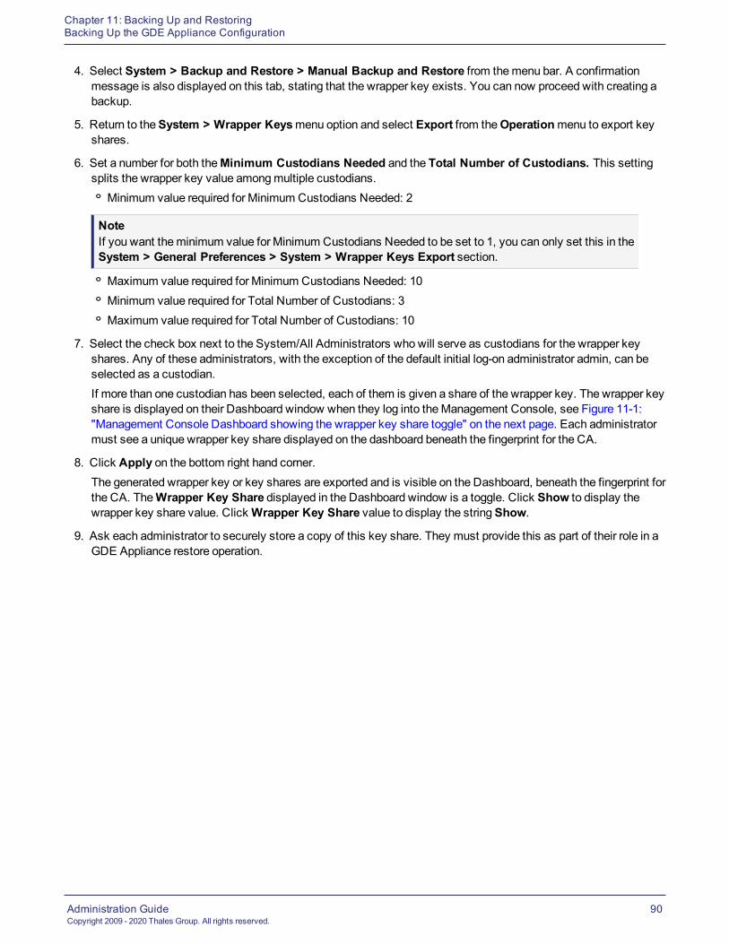
Chapter 11: Backing Up and RestoringBacking Up the GDE Appliance Configuration
Administration GuideCopyright 2009 - 2020 Thales Group. All rights reserved.
90
4. Select System > Backup and Restore > Manual Backup and Restore from themenu bar. A confirmationmessage is also displayed on this tab, stating that the wrapper key exists. You can now proceed with creating abackup.
5. Return to theSystem > Wrapper Keysmenu option and select Export from theOperationmenu to export keyshares.
6. Set a number for both theMinimum Custodians Needed and the Total Number of Custodians. This settingsplits the wrapper key value amongmultiple custodians.o Minimum value required for Minimum Custodians Needed: 2
NoteIf you want theminimum value for Minimum Custodians Needed to be set to 1, you can only set this in theSystem > General Preferences > System > Wrapper Keys Export section.o Maximum value required for Minimum Custodians Needed: 10o Minimum value required for Total Number of Custodians: 3o Maximum value required for Total Number of Custodians: 10
7. Select the check box next to the System/All Administrators who will serve as custodians for the wrapper keyshares. Any of these administrators, with the exception of the default initial log-on administrator admin, can beselected as a custodian.If more than one custodian has been selected, each of them is given a share of the wrapper key. The wrapper keyshare is displayed on their Dashboard window when they log into theManagement Console, see Figure 11-1:"Management Console Dashboard showing the wrapper key share toggle" on the next page. Each administratormust see a unique wrapper key share displayed on the dashboard beneath the fingerprint for the CA.
8. Click Apply on the bottom right hand corner.The generated wrapper key or key shares are exported and is visible on the Dashboard, beneath the fingerprint forthe CA. TheWrapper Key Share displayed in the Dashboard window is a toggle. Click Show to display thewrapper key share value. ClickWrapper Key Share value to display the stringShow.
9. Ask each administrator to securely store a copy of this key share. They must provide this as part of their role in aGDE Appliance restore operation.
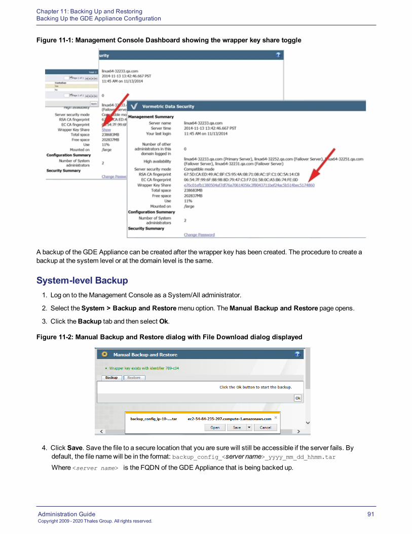
Chapter 11: Backing Up and RestoringBacking Up the GDE Appliance Configuration
Administration GuideCopyright 2009 - 2020 Thales Group. All rights reserved.
91
Figure 11-1: Management Console Dashboard showing the wrapper key share toggle
A backup of the GDE Appliance can be created after the wrapper key has been created. The procedure to create abackup at the system level or at the domain level is the same.
System-level Backup1. Log on to theManagement Console as a System/All administrator.
2. Select theSystem > Backup and Restoremenu option. TheManual Backup and Restore page opens.
3. Click theBackup tab and then select Ok.
Figure 11-2: Manual Backup and Restore dialog with File Download dialog displayed
4. Click Save. Save the file to a secure location that you are sure will still be accessible if the server fails. Bydefault, the file namewill be in the format: backup_config_<server name>_yyyy_mm_dd_hhmm.tarWhere <server name> is the FQDN of the GDE Appliance that is being backed up.

Chapter 11: Backing Up and RestoringPer Domain Backup and Restore
Administration GuideCopyright 2009 - 2020 Thales Group. All rights reserved.
92
5. Save the backup to a secure location. Access to the backup should be limited to only a few employees andshould be audited.
Per Domain Backup and RestoreIn addition to a creating a backup of the GDE Appliance, you can also back up and restore the configurationinformation for a single domain. A domain backup can be restored to:
l The same domain
l To a different domain on the sameGDE ApplianceIf a domain backup is restored to a different domain on the sameGDE Appliance, theremay be a host nameconflict, in which case the host names must be changed.
l To a different domain on another GDE Appliance
WARNINGA backup containing a KMIP domain must be restored with the same name. You cannotrestore it with a different name, unlike a standard domain.
To create a backup of a domain and to restore that backup, a wrapper key must be created for the domain, and thedomainmust have an assigned Domain Administrator. The backup and restore operations are done by a Domain,Domain and Security Administrator, or an All administrator from within the domain to be backed up or restored.
Domain-level Backup1. Log on to theManagement Console as a Domain, Domain and Security or All Administrator, or switch to the
domain that you want to backup.
2. Select theSystem > Backup and Restoremenu option. TheManual Backup and Restore page opens.
3. Click theBackup tab and click Ok to start the backup.
4. Click Save in the File Download dialog box. Save the file to a secure location that you are sure will still beaccessible if the server fails. By default, the file namewill be in the format: backup_config_<domain name>_<server name>_yyyy_mm_dd_hhmm.tarWhere <domain_name> is the name of the domain being backed up and <server name> is the FQDN of the GDEAppliance that is being backed up.
5. Save the backup to a secure location. Access to the backup should be limited to only a few employees andshould be audited.
Restoring BackupsA backup of the GDE Appliance can be used to restore the hosts, encryption keys, and policies, as well as otherconfiguration information of a GDE Appliance, after a software crash recovery or system change. A GDE Appliancebackup can be restored at the system level or at the domain level.
The procedure to restore a domain-level backup is the same as the procedure to restore a system-level backup. Torestore a domain level backup, youmust be logged into that domain.
TheGDE Appliance backup is restored via theManagement Console.

Chapter 11: Backing Up and RestoringAutomatic Backup
Administration GuideCopyright 2009 - 2020 Thales Group. All rights reserved.
93
Restoring the GDE Appliance from a backup
The following procedures describe:
l How to do a system-level restore of a GDE Appliance from a backup
l How to do a domain-level restore of a GDE Appliance from a backup
Notesl Following a restore operation, the GDE Appliance configuration in theManagement Console isreplaced by the configuration stored in the backup copy. Any new encryption keys, policies, hosts,or GuardPoints added since the last backup will be overwritten and lost.
l Unless this is a disaster recovery scenario where all GDE Appliances have been lost, alwaysbackup the current configuration before running a restore operation.
Automatic BackupTheGDE Appliance system configuration information can be scheduled to be automatically backed up on a daily orweekly basis using the Automatic Backup feature.
Automatic backups can also be configured at the domain level. To schedule an automatic backup at the domain level,youmust be logged into the domain for which the backup is to be scheduled.
In addition to scheduling a backup, there is also an option to run a scheduled backup immediately and push the backupfile to a configured external file server. To do this, youmust access a File Server (a UNIX orWindows host) that isnetwork accessible by the GDE Appliance to store the backup files.
The procedure to schedule an automatic backup is the same at the system level and at the domain level.
Schedule an Automatic BackupThe automatic feature works the sameway for a per domain automatic backup as for a host backup.
1. Select System > Backup and Restore > Automatic Backup in theManagement Console, to open theAutomatic Backup page.
2. Enter the settings for theAutomatic Backup Schedule and theExternal File Serverwhere the backup fileswill be stored.
3. Enter the following information in theAutomatic Backup Schedule section:
4. Active Schedule: Choose either Daily orWeekly, the default is Weekly.
5. Time: Based on a 12-hour clock and the A.M./P.M. modifiers. Time is relative to the GDE Appliance systemclock.
6. Weekday: Select the day of the week on which to backup theGDE Appliance.
7. Enter the following information in theExternal File Server Settings section:
8. Active Settings: Select SCP, SFTP orWindows Share. This configures themode in which to copy thegenerated backup file to the remote system. SSH must be configured on the destination system to use SCP orSFTP mode. The selectedmode determines the subsequent configuration parameters that must be entered

Chapter 11: Backing Up and RestoringAutomatic Backup
Administration GuideCopyright 2009 - 2020 Thales Group. All rights reserved.
94
Figure 11-3: Automatic Backup Schedule for SCP
SCP and SFTPIf you select SCP orSFTP, enter the following information (all fields marked with a red asterisk are required):
l This Server Security's Credential: Click to ExportClick this to download the GDE Appliance server's public key. Copy the public key onto the destination systemand into ../user/.ssh/authorized_keys. The public key is required to use SCP to copy the backup file to theexternal file server.
l Target HostEnter the host name, IP address, or FQDN of the destination system. If the destination system has a FileSystem Agent, you do not have to use the same host name as configured in the Hosts window. You can use anyrecognizedmeans of addressing the destination system, just as long as it is recognized on your network.
l Target Host FingerprintThe fingerprint value displayed is the fingerprint of the GDE Appliance public key that is currently on thedestination system. The fingerprint is retrieved from the destination system and displayed in the AutomaticBackup page during a backup. You can verify if the public key on the destination system is current by comparingthe key in ~user/.ssh/authorized_keys on the destination system with the key generated by Click to Export.
l Target DirectoryEnter the full path of the directory in which to copy the backup file.
l User Name:Enter the name of the user to perform the copy operation. The name enteredmust be a valid user on thedestination system. Also, copy the public key into the ../.ssh/authorized_keys file in the home directory ofthe user you specify in this text-entry box. A password is not required for the SCP user because a public key isused to authenticate the SCP user.
Windows ShareIf you selectWindows Share, enter the following information (all fields marked with a red asterisk are required):
l Network HostHost name, IP address, or FQDN of the destination system.
l Network DirectoryThe shared folder path to which to copy the backup file.

Chapter 11: Backing Up and RestoringAutomatic Backup
Administration GuideCopyright 2009 - 2020 Thales Group. All rights reserved.
95
l User NameThe name of the user to perform the copy operation. The name enteredmust be a valid user on the destinationsystem.
l PasswordThe password for User Name. Sometimes a domain is required for user authentication. To include the userdomain, append the domain to the user name in the form user@domain. For example,[email protected].
NoteSpecial characters like vertical bar (|), single quote ('), double quote (") and space ( ) are not supported
l Confirm PasswordRe-enter the password for User Name.
l Click Ok to save the configuration settings currently displayed on the Automatic Backup page, changes to thesettings are stored in cache until you click Ok.
Figure 11-4: Automatic Backup schedule for Windows Share
1. Click Ok to save the configuration settings or click Backup Now to immediately create a backup using thecurrent configuration. This is an easy way to the test network connection and login credentials of theconfiguration settings you just made.
2. After a successful backup, look in the specified Target Directory on the Target Host to see the backup tar file.
Schedule an immediate backupYou can also schedule an immediate backup once you havemade all your selections:
l Click Backup Now to create a backup immediately using the current configuration.This is an easy way to the test network connection and login credentials of the configuration settings you justmade.

Chapter 11: Backing Up and RestoringAutomatic Backup
Administration GuideCopyright 2009 - 2020 Thales Group. All rights reserved.
96
Remove schedule and settingsClick Remove Schedule and Settings to clear all the fields in both the Daily andWeekly configurations. For SCPand SFTP mode backups, this means the public key is removed, and a new one has to be generated. This new publickey has to be copied to the destination system.
A new public key is automatically downloaded the next time you click Click to Export. If you create a new key thisway, youmust also update the ~/.ssh/authorized_keys file on the destination system because the SSH credentialshave changed and will no longer be valid.

Administration GuideCopyright 2009 - 2020 Thales Group. All rights reserved.
97
Chapter 12: High Availability (HA)High Availability Overview 97Synchronization Status on the Dashboard 97HA Cluster Status 100HA Topology 101Recovering from incomplete node synchronizations 102Assigning VTE Agent Hosts to HA Nodes in an HA cluster 103Best Practices for HA Clusters 103
High Availability (HA) is the configuration of multiple GDE Appliances in an HA cluster. Each node runs in parallel.This means there is no longer a primary nor a failover node. All nodes are peers.
High Availability OverviewHigh Availability (HA) is now configured as Active-Active. This means that all nodes are equal and running in parallel.For example, you can assign GuardPoints and rekey data on any node.
Only GDE Appliance System/All Administrators are permitted to configure HA for GDE Appliances.
When oneGDE Appliance HA node fails, the other HA nodes in the HA cluster continue to run. When the downedGDE Appliance HA node is up and running again, it synchronizes with the other GDE Appliance HA nodes.
HA configuration andmaintenance is done in both the GDE Appliance CLI and the UI Management Console.
HA node 1 acts as the Certificate Authority (CA) and creates signing certificates. Once that HA node is configuredwith its own certificates, it pushes the certificates to other HA nodes when they join the cluster.
Multi-way communication exists between the HA nodes. When a node changes, it synchronizes with all of the otherHA nodes.
Because the HA nodes run in parallel, all HA nodes have the sameRSA CA and EC CA fingerprints (for example,5X:5A:51:93:ED:53:B9:8A:1Z:FG:72:3A:BG:60:FV:3Q:CE:F7:69:95).
NoteFor configuration information, see theHA for V6X00 and Virtual Appliances chapter in theGDEAppliance Installation and Configuration Guide.
Synchronization Status on the DashboardTheManagement ConsoleDashboard page on all HA nodes displays the high availability synchronization status andthe Host assignments.

Chapter 12: High Availability (HA)Synchronization Status on the Dashboard
Administration GuideCopyright 2009 - 2020 Thales Group. All rights reserved.
98
Figure 12-1: Dashboard HA Status
High availability synchronization statusOn the Dashboard, next to the term High Availability, the GDE Appliance displays the status and a parallel icon. InFigure 12-1: "Dashboard HA Status" above the High Availability status displays as Normal, with a green icon. Clickingthe green icon takes you to the High Availability Servers page.
NoteIf you are logged into a domain, you will not see this because domains do not have access to HA.
If high availability has been configured, the FQDN of the HA node(s) display with a synchronization status icon next tothe node(s). The icon indicates the status of the HA node.
Clicking the icon next to the HA node link takes you to the Server Node page of the HA node that you clicked on.
The Server Node page on displays the following:
l FromDisplays the name of the HA node trying to synchronize.
l ToDisplays the name of the HA node with which it is trying to synchronize.
l Status Collection TimeThe time shown in this column indicates the last successful synchronization between the HA nodes.
l HA Replication StatusShows the synchronization status between the nodes.
Dashboard Host AssignmentThe Dashboard also displays the status of VTE Agent hosts assigned to the HA cluster.
l If all of the hosts are assigned to nodes, then themessage displayed is: All Hosts are Assigned.l If some of the hosts are not assigned to nodes, then themessage displayed is: “SomeHosts are not Assigned to
a Server Node, Configuration Changes will not be Pushed to These Hosts.”When you click on that message, itdisplays the names of the hosts that are not assigned.

Chapter 12: High Availability (HA)Synchronization Status on the Dashboard
Administration GuideCopyright 2009 - 2020 Thales Group. All rights reserved.
99
Figure 12-2: Hosts not assigned to nodes
If you have hosts that are not assigned, you can assign them to any nodes in the HA cluster. See the HA forV6X00 and Virtual Appliances chapter in the GDE Appliance Installation and Configuration Guide for moreinformation.
Display HA configuration status1. Log on to theManagement Console as a System/All Administrator.
2. Select High Availability in themenu bar. The High Availability Servers window opens. It displays the HA nodes.
Column Header Description
Selected Select an HA node to delete the node from the HA cluster.
Name Displays the fully qualified domain name (FQDN) of the HA node.
Response Time (ms) Displays the response time in milliseconds, if SNMP is enabled. If SNMP is enabled, anHA node polls the other HA nodes using an SNMP GET request. If SNMP is disabled, theResponse Time column displays “SNMP Disabled”. If the connection is lost, the ResponseTime column displays “Not Reachable”.
Configured A check mark in this column indicates that the node is configured and can be accessed byany registered VTE Agents for policy and/or key changes.
SynchronizationStatus
Shows the synchronization status between the HA nodes. A green circle indicatessynchronization between the HA nodes. A red rectangle indicates a synchronization error.
Table 12-1: High Availability Servers window fields information
The buttons on the High Availability Servers window are:
l AddOpens the Add Server window in which to add the host name or FQDN of another HA node.
l DeleteRemoves the selected node from the HA cluster.
l Notify All HostsPushes the latest VTE Agent host configurations to every VTE Agent host in the HA cluster.If policy changes are not being applied to the hosts that are assigned to an HA node, check theHigh Availabilitywindow.o A green circle should be displayed for all of the HA nodes.o A red rectangle in theSynchronization Status column indicates that an error has occurred.

Chapter 12: High Availability (HA)HA Cluster Status
Administration GuideCopyright 2009 - 2020 Thales Group. All rights reserved.
100
o Check the network connection between the HA nodes and check that the software is running (for instance,open aWeb browser to another HA node). When a host is assigned to another node, policy configurationchanges are synchronized on the HA node, and then pushed to the host. If the HA node is going to be downfor an extended period, reassign the hosts to another HA node in the cluster. You can also click Notify AllHosts to push policy changes to all the hosts assigned to the GDE Appliance, regardless of which GDEAppliance they are assigned.
HA Cluster StatusYou canmonitor the communication status between nodes in the cluster. Communication is now bi-directional andmay not be the same between all nodes.
From the High Availability Servers page, if you click on the name of an HA server, the link takes you to the ServerNode page for the selected HA node.
The Server Node page displays the following:
l FromDisplays the name of the HA node trying to synchronize.
l ToDisplays the name of the HA node with which it is trying to synchronize.
l Status Collection TimeIndicates the time of the last successful synchronization between the HA nodes.
l HA Replication StatusShows the synchronization status between the nodes. Communication is bi-directional.
Server Node HA StatusTo findmore details on the HA Replication Status, click on the icon to open the Server Node HA Status dialog. Thestatus information listed is:
l Warning messageError (Red), Warning (yellow), Normal (green)
l FromNode from which the status query originates.
l ToNode queried.
NoteThe HA status view no longer shows bi-directional status. It only lists the direction from the node to othernodes. Multi-directional status is illustrated in "HA Topology" on the facing page.
l Node StatusDescribes the node status:o ReadyNode is fully functional.
o Joining

Chapter 12: High Availability (HA)HA Topology
Administration GuideCopyright 2009 - 2020 Thales Group. All rights reserved.
101
Node is bootstrapping. This state occurs when the join has been initiated but synchronizing has not yet beenbegun.
o JoiningNode is creating an initial replication slot so that it can communicate with the cluster.
o JoiningData is transferring to the joining node. The transfer is almost complete.
o JoiningData is transferred. Node is preparing to join the cluster as a peer.
o Parting/PartedNode is removed from the cluster by the user.
l Slot StatusStatus of channel used to communicate with the cluster.
l Byte LagAmount of data available for a node to consumewhen another node changes, measured in number of bytes.
l Time Lag (sec)Difference between the current time on a node and the observed time reported by another node.
l Ping Response Time (ms)Amount of time the ping query took between nodes.
l Status Collection TimeLast time cluster nodes were queried for status.
Setting up HA monitoring for Server Node HA StatusTo set up the values for the HA monitoring parameters that display in the Server Node HA status dialog:
1. Click System > General Preferences > HA Monitoring.
2. Set the following parameters:o HA Node Status Update IntervalSet the interval in minutes, (min: 5; max: 59).
o HA Status Time Lag WarningSet the interval in seconds, (min: 60 + update-interval)
o HA Status Time Lag ErrorSet the interval in seconds, (> time-lag-warning)
o HA Status Byte Lag WarningSet the interval in bytes, (min: 16384)
o HA Status Byte Lag ErrorSet the interval in bytes, (> byte-lag-warn)
HA TopologyHA Topology provides a graphical representation of the HA Cluster node topology. The diagram links in all directions,as indicated by the arrows, from each node to every other node. The edges are color coded to reflect their status: green(normal), yellow (warning), and red (error).

Chapter 12: High Availability (HA)Recovering from incomplete node synchronizations
Administration GuideCopyright 2009 - 2020 Thales Group. All rights reserved.
102
NoteThe HA topology map updates after each node synchronization.
In the following topology map, the yellow lines indicate that system Sys66084.qa.com is having a connection problemwith the cluster and the rest of the nodes cannot communicate with it at all. The remaining nodes are communicatingproperly with the other nodes in the cluster.
Figure 12-3: HA Topology for 8 Nodes
Recovering from incomplete node synchronizationsIf the HA nodes do not synchronize completely after replication, do the following to re-initialize an HA node:
1. Remove all nodes from the HA cluster.
2. Run cleanup on each node.
3. Add them back into the HA cluster.
4. Join the HA cluster again.
If the nodes still do not synchronize:
1. In the CLI for the HA node that is not synchronizing properly, go to theMaintenancemenu.
2. Reset the HA node, type:
0001:maintenance$ config reset
3. Type yes to continue with the reset.
4. Reconfigure the node.

Chapter 12: High Availability (HA)Assigning VTE Agent Hosts to HA Nodes in an HA cluster
Administration GuideCopyright 2009 - 2020 Thales Group. All rights reserved.
103
See the HA for V6X00 and Virtual Appliances chapter in the GDE Appliance Installation and Configuration Guide formore information.
Assigning VTE Agent Hosts to HA Nodes in an HA clusterYou can assign VTE agents to any node in an HA cluster. Because the HA nodes are constantly synchronizing, withina few seconds, the VTE agent is available on all nodes in the HA cluster.
Every GDE Appliance can check the status of every host in an HA configuration. Each host must have networkaccess to an HA node. It does not have to be an uninterrupted connection, but is required to register the agent and forthe node to query the host status. Each host must be on the same network as every node so that it can check the hoststatus.
The Notify All Hosts button in theHigh Availability Servers window pushes the latest host configurations directly fromany GDE Appliance HA node, to every host in the HA cluster, regardless of which the HA node they are assigned. Ifyou are unsure of how many hosts may be out of sync with their assignedGDE Appliance, click the Notify All Hostsbutton in the High Availability Servers window. This is a convenient way to push the latest host configuration changesto every host, including orphan hosts.
Depending on the number of hosts in the HA cluster and network performance, this can take between a few minutes toa few hours. Check the push status in the Logs window. Messages are placed in the log at intervals to indicate thepercentage of completion.
NoteDo not click Notify All Hosts more than once. Each time you click this button you create a new processand each new process slows theGDE Appliance.
VTE Agent AvailabilityThe following describes the high-level process for how a VTE agent joins the HA cluster and becomes available to allof the HA nodes in the cluster:
1. A VTE agent registers to a GDE Appliance node that is part of an HA cluster.
2. User adds the VTE host to the HA cluster through theGDE ApplianceManagement Console.
3. The HA node synchronizes with all of the HA nodes.
4. The VTE agent is now available to all HA nodes in the cluster.
Best Practices for HA ClustersIn an HA cluster, the architecture has changed to peer nodes. Therefore, if people are working on the same object ondifferent HA nodes simultaneously, there is a possibility for conflicts.
For example, if two administrators modify the same policy on different HA nodes at the exact same time, the initialmodifications will be lost. Only the last operation, meaning the one with the latest timestamp, is saved.
To avoid data conflicts, Thales recommends that you do the following:
l Manage the HA cluster from one dedicated GDE Appliance node
l Alternatively, partition the data andmanage one partition data in one dedicated nodeFor example, you could create domains for different geographic regions, and thenmanage the domains with theGDE Appliance HA node for that region

Chapter 12: High Availability (HA)Best Practices for HA Clusters
Administration GuideCopyright 2009 - 2020 Thales Group. All rights reserved.
104
l If you use the RESTful API, and VMSSC, tomanage theGDE Appliance HA nodes, do not put any load balancerin front of the GDE Appliance HA cluster nodes
l Use the sameGDE Appliance HA node for datamanagement for a particular job.For example, if you create and register a host to oneGDE Appliance HA node, then perform all host operations,such as adding GuardPoints, on that sameGDE Appliance HA node.
In general, avoid managing the same objects from different GDE Appliance HA nodes.

Administration GuideCopyright 2009 - 2020 Thales Group. All rights reserved.
105
Chapter 13: Multifactor Authentication with RSAOverview 105Configuring RSA Authentication 106Additional RSA configuration notes 106
Multifactor authentication increases access control to the GDE ApplianceManagement Console by requiring GDEAppliance administrators to enter the value or token code displayed on an RSA SecurID token, along with theadministrator name, each time the administrator logs into theManagement Console.
OverviewMultifactor authentication on theGDE Appliance comprises the GDE Appliance, the RSA AuthenticationManager, theRSA Authentication Agent, and an RSA SecurID token. The usual sequence is:
1. Configure the GDE Appliance HA nodes in the same cluster as the RSA Authentication Agents in the RSASecurity Console
2. Create an RSA user ID in the RSA Security Console window
3. Assign the SecurID token to the RSA User ID
4. Test the SecurID token in the RSA self-service console tomake certain it is working properly
5. Import the RSA Authentication Agent file into the GDE Appliance
6. Associate the RSA user ID to aGDE Appliance administrator
7. Enablemultifactor authentication
From this point on, a GDE Appliance administrator must enter the GDE Appliance administrator name, the RSA staticPIN (if the GDE Appliance administrator ID requires the use of one), and the value displayed on the SecurID tokenknown as a token code, to log into the GDE ApplianceManagement Console.
Figure 13-1: Configuring multifactor authentication

Chapter 13: Multifactor Authentication with RSAConfiguring RSA Authentication
Administration GuideCopyright 2009 - 2020 Thales Group. All rights reserved.
106
Configuring RSA AuthenticationThe RSA Authentication Agent is the intermediary betweenGDE Appliance and the RSA AuthenticationManager. TheRSA Authentication Agent intercepts an access request from theGDE Appliance and directs the request to the RSAAuthenticationManager server for authentication.
An initial link betweenGDE Appliance and the RSA AuthenticationManager is created when an RSA configurationfile, sdconf.rec, is imported into the GDE ApplianceManagement Console. The first time the RSA AuthenticationAgent authenticates an administrator with the RSA AuthenticationManager, the RSA Authentication Agent nodesecret is copied and embedded in the GDE Appliance.
You can delete the node secret using the mfauth cleanCLI command. If you delete the node secret, also delete itfrom the RSA Security Console, and vice versa. This command removes the SecurID file from GDE Appliance. Areplacement node secret file is automatically downloaded to GDE Appliance the next time aGDE Applianceadministrator logs in with an RSA token code
Youmust regenerate the node secret file in the RSA AuthenticationManager if the GDE Appliance installation isdestroyed and rebuilt because the GDE Appliance authentication credentials are no longer valid.
Multifactor authentication status information is displayed on theGDE Appliance Logs page.
Oncemultifactor authentication is configured, RSA AuthenticationManager andGDE Appliance startup/shutdownsequence is important.
l Start the RSA AuthenticationManager before the GDE Appliance.
l Shutdown theGDE Appliance before the RSA AuthenticationManager.
This sequence is required to ensure that the RSA Authentication Agent can reliably access the RSA AuthenticationManager.
Additional RSA configuration notesThe following are additional points to consider when configuring or troubleshooting an RSA configuration.
1. If you are configuring an existing GDE Appliance Authentication Agent setup, go toAccess > AuthenticationAgents > Manage Existing.
2. Choose AuthenticationAgent > Manage Node Secret.
3. Select Clear the node secret.
4. Save your changes.o If you are configuring a new GDE Appliance Authentication Agent setup, you do not need to go toManageNode Secret.
The RSA AuthenticationManager server requires the IP address and hostname of the GDE Appliance. If DNS isconfigured, the IP address or hostnamemust be able to be resolved from the RSA AuthenticationManager SecurityConsole.
Alternatively, you can edit the /etc/hosts file on the GDE Appliance and add theGDE Appliance IP address and hostname. Use the host name to configure the RSA Authentication Agent.
Administration GuideCopyright 2009 - 2020 Thales Group. All rights reserved.
107
Chapter 14: Viewing and Downloading System-LevelReports
Overview 107Viewing and Downloading Reports 107System-Level Reports 107
TheGDE Appliance comes with pre-configured reports that display system information. All reports can be downloadedand saved locally in CSV format.
OverviewAll reports are under theReports tab. The availability of reports depends on theGDE Appliance administrator type andprivileges, and whether the administrator is currently in or out of a domain.
l All Administrators can access all system reports and global domain reports. See Chapter 17: "Viewing andDownloading Domain-Level Reports" on page 131 for more information about domain-level reports.
l System Administrators can access system reports outside global domains.
Viewing and Downloading ReportsTo view a report, click theReport tab on theManagement Console, and then click the name of the report.
To save the report as a CVS file to your local machine, click Download at the top left of the report table.
System-Level ReportsThe following reports are available to System/All administrators:
l "Administrators" below
l "Servers" on the next page
l "Security Domains" on the next page
l "Executive Summary" on the next page
Youmust be outside of a domain to access system-level reports.
AdministratorsThe Administrators report is a table of administrators with access to the GDE Appliance.
Column Name Description
User Name Login
User Type System Administrator, Security Administrator, DomainAdministrator, Domain and Security Administrator, and All
LDAP User ID The UserID of a user imported from LDAP
Table 14-1: Administrators

Chapter 14: Viewing and Downloading System-Level ReportsSystem-Level Reports
Administration GuideCopyright 2009 - 2020 Thales Group. All rights reserved.
108
Column Name Description
Last Login Time The time of this user’s last login. Timestamps are in the formYYYY-MM-DD HH:MM:SS where Y=year,M=month, D=day,H=hour,M=minute, S=second
Table 14-1: Administrators (continued)
ServersThe Servers report is a table of HA clusters of servers.
Column Name Description
Server Name FQDN of the GDE Appliance
Up Time How long the GDE Appliance has been active
Table 14-2: Server Report
Security DomainsThe Security Domains report is a table of Security domains managed by this GDE Appliance.
Column Name Description
Organization Name of the organization responsible for this domain
Domain Name Name of the domain set when the domain was created.
Description User added information
Help Desk Information Phone number of tech support
Domain Administrators Names of the Domain Administrators assigned to this domain.
Security Administrators Names of the Security Administrators assigned to this domain.
Domain and Security Administrators Names of the Domain and Security administrators assigned tothis domain.
All Administrators Names of the All administrators who can access this domain.
Table 14-3: Security Domains
Executive SummaryThe Executive Summary Report shows the totals for the following entities:
l Asymmetric Keys
l GuardPoints
l Hosts (Encryption Expert agents)
l Policies
l Security Domains
l Security Server Administrators

Chapter 14: Viewing and Downloading System-Level ReportsSystem-Level Reports
Administration GuideCopyright 2009 - 2020 Thales Group. All rights reserved.
109
l Security Servers
l Symmetric Keys

Administration GuideCopyright 2009 - 2020 Thales Group. All rights reserved.
110
Chapter 15: Domain and Security AdministratorsOverview 110Assigning Domain Administrators or Security Administrators to Domains 110Security Administrator Roles 113Assigning Security Administrator Roles 114Preventing Security Admins from Disabling Domain Admins 114
OverviewSystem Administrators create domains but do not operate within them. However, all tasks performed by the DomainAdministrators and Security Administrators occur within domains. The Domain Administrators and SecurityAdministrators must always know what domain they are in before executing any task. If you log in as a DomainAdministrator or a Security Administrator, and you notice that the administrator, host, or log data is unexpected, youaremost likely in the wrong domain.
Domain Administrators can add additional Domain Administrators to each domain. A Global Domain Administrator canbe amember of multiple domains. Domain Administrators who aremembers of multiple domains can easily switchbetween the domains. They can also add Security Administrators to a domain and assign roles to these SecurityAdministrators (for example, Audit, Key, Policy, Host, Challenge & Response, and/or Client Identity) that are appliedonly within that domain.
Local or restricted Domain Administrators are restricted to a particular domain. The first Domain Administrator isadded to a restricted domain by the System Administrator. After that, the local Domain Administrator creates and addsother Domain or Security Administrators to the Domain as required. Local Domain Administrators and SecurityAdministrators aremembers of the local domain they are created within, they cannot bemembers of any other domain.Once created and assigned to a local domain, they are not visible to administrators of other domains.
Domain Administrators cannot remove domains or perform in any of the domain security roles.
A Domain Administrator can:
l Enable and disable Domain Administrator and Security Administrator accounts in the current domain (globalDomain Administrators).
l Create, delete, import, enable or disable Domain Administrator and Security Administrator accounts in the currentdomain (local or restricted Domain Administrators).
l Configure Security Administrator roles (Audit, Key, Policy, Host, Challenge & Response, Client Identity).
l Prevent System Administrators from disabling Domain administrators from within a domain
NoteWhen aDomain Administrator changes the configuration of a Security Administrator or another DomainAdministrator, the current Management Console session for that administrator is terminated and thatadministrator must log back in. If a Domain Administrator is removed from a domain, the DomainAdministrator cannot switch to or do any work in that domain.
Assigning Domain Administrators or Security Administrators toDomainsThere are two types of Domain Administrators that can be created on theGDE Appliance:
l Global Domain Administrators

Chapter 15: Domain and Security AdministratorsAssigning Domain Administrators or Security Administrators to Domains
Administration GuideCopyright 2009 - 2020 Thales Group. All rights reserved.
111
l Local (or restricted) Domain Administrators
A System Administrator adds the first Domain Administrator to a global domain. A global Domain Administrator canadd and remove additional administrators (Domain, and Domain and Security) to domains. But, a global DomainAdministrator cannot delete administrator accounts.
A System Administrator adds the first Domain Administrator to the restricted domain. The local Domain Administratorcan then create new administrators (Domain, Security, or Domain and Security), in the domain, or import LDAP usersandmake them Domain, Security, or Domain and Security Administrators within the local domain. A local DomainAdministrator can also delete those administrator accounts.
A System Administrator can delete global Domain Administrators, but cannot delete local Domain Administrators asthey are not visible to the System Administrator. The System Administrator can, however, disable the local DomainAdministrator that they added to a local domain.
Add Global Domain or Security Administrators to a domain1. Log in as a Domain, Domain and Security, or All administrator. The Dashboard window opens.
2. Switch to the domain to which you want to add Domain or Security Administrators.a. Select Domains > Switch Domains.
The Domains window opens. All the domains in which the current Administrator is amember, are displayed.TheSelected radio button of the current domain is grayed out and cannot be selected.
b. Select the radio button of the domain.If the domain is not listed, ask the Domain, Security, Domain and Security, or All Administrator for thatdomain to add you to it.
c. Click Switch to Domain. The Domains window displays.
3. Select Administrators > Domain. The Administrators window opens and displays all of the Administrators whoaremembers of the current domain.
4. Click Add to Domain. The Available Administrators window opens. This window lists all the Administrators whoare not already assigned to the current domain.
5. Enable theSelected check box of the Administrator you want to add to the current domain.
6. If you are adding a Security Administrator, you also need to assign roles to that Security Administrator. Select theadministrator role check boxes (Audit, Key, Policy, Host, Challenge & Response, and/or Client Identity) toenable these features.Domain and Security Administrator are automatically assigned the following roles: Key, Policy, Host, Challenge& Response and Client Identity. If you want a Domain and Security Administrator to have the Audit role, youmust enable that role by selecting the checkbox for Audit.
7. Click Ok. The Administrators added to the domain are now active.
Add Local Domain or Security Administrators to a restricted domain1. Log on to the GDE Appliance as a Domain, Domain and Security, or All administrator with your local Domain
Administrator credentials. Youmust select the local domain option, and then enter the local domain name in theDomain Name field. The Dashboard window opens.
2. Navigate to the Administrators window.
3. Click New to create a new Domain, Security, or Domain and Security Administrator.
4. In the Add Administrators window, enter the following information:

Chapter 15: Domain and Security AdministratorsAssigning Domain Administrators or Security Administrators to Domains
Administration GuideCopyright 2009 - 2020 Thales Group. All rights reserved.
112
o LoginType a user name for the administrator, it must contain at least 5 characters with an upper limit of 36characters. Only one instance of an administrator name is allowed.
o Description (Optional)Enter a description that helps you identify the administrator. Themaximum number of characters for this fieldis 256.
o PasswordEnter a password for the administrator. The passwordmust conform to the attributes defined in the passwordpreferences, themaximum password length is 256 characters. The newly created administrators will have tochange this password the first time they log on to the GDE Appliance.
o Confirm PasswordRe-type the password to confirm.
o User TypeSelect the type of administrator to create: Domain Administrator, Security Administrator, or Domain andSecurity Administrator.
o Read-Only UserSelect this check box to create an administrator with read-only privileges. You can assign read-only privilegesto any type of administrator, except for Local Domain administrators that are the first administrators to beassigned to a domain. If the first administrator added to a local domain is read-only, that administrator will notbe able to create any more administrators for that domain.
5. Click Ok. The new administrator is displayed in the table on the Administrators page.
6. Click Import to import LDAP users to assign as GDE Appliance Administrators. You have to have an LDAPServer configured in order to import these users, see Chapter 8: "Using an LDAP Server" on page 58 for details.
7. Enter the Login and Password for the LDAP server. If the Login and Password were entered under LDAP ServerSettings on the AD/LDAP Details window, these values will be populated and do not need to be re-entered. Youmay also enter a different Login and Password in place of these stored values when you import administrators.Click Connect. The LDAP Users window displays LDAP user names.
8. Select LDAP Users:The following search option are available on the LDAP Users window:o LDAP QueryUse the field to filter searches using the LDAP query language. Results depend on how the LDAP service isset up. See RFC2307 for full details on syntax.
o GroupSelect a group from the drop down list.
o UserEnter a user name.
o Maximum number of entries to returnLimits themaximum number of records to import or display. The default value is 300. Theminimum value is 1and themaximum value is 10,000. A high integer valuemay result in a delay depending on the database size.
o GoClick to refresh the screen.
o Select AllClick to select all values on that page.

Chapter 15: Domain and Security AdministratorsSecurity Administrator Roles
Administration GuideCopyright 2009 - 2020 Thales Group. All rights reserved.
113
o ViewSelect a value from this drop down box to control how many values appear on any page.
o SelectedClick to select individual values.
o User TypeSelect a value from this drop down box to define the type of Administrator or role of the values you import.
o Add/CancelSelect to add or cancel your selections.
Security Administrator RolesA Security Administrator can be configured with one or more roles. Domain Administrators assign roles when theyassign a Security Administrator to a domain. The roles are applicable only in the current domain. A SecurityAdministrator can be assigned different roles in different domains.
Role Description
Audit The audit role can only view log data.
Key The key role can create, edit, and delete local key-pairs, public keys, and key groups.Administrators with this role can also view log data.
Policy The policy role can create, edit, and delete policies. Administrators with this role can alsoview log data.
Host The Host role can configure, modify, and delete hosts and host groups. Administrators withthis role can also view log data. The Challenge & Response role is automatically selectedwhen the Host role is selected.
Challenge & Response The Challenge & Response role must be enabled for a Security Administrator to view theHost Password Challenge & Response window. The window is used to enter a challengestring and display the response string. The response string is a temporary password that asystem user enters to decrypt cached encryption keys when there is no connection to theGDE Appliance.The Challenge & Response role is automatically enabled when the Host role is enabled.You may disable the Host role afterward to leave just the Challenge & Response roleenabled. With just this role enabled, the Security Administrator has access to theDashboard, Domains > Switch Domains, and Hosts > Host Password Challenge &Response menus only.A Security Administrator can open both the Hosts > Host Password Challenge &Response window and the Hosts > Hosts > Challenge Response tab with the Host andChallenge & Response roles assigned. With just the Challenge & Response roleassigned, the Security Administrator can open only the Hosts > Host PasswordChallenge & Response window.
Client Identity The Client Identity role must be enabled for a Security Administrator to create Identity-Based Key Access. A client identity is used to control access to encryption keys on theGDE Appliance by VAE host administrators.
Table 15-1: Security Administrator roles and permitted tasks

Chapter 15: Domain and Security AdministratorsAssigning Security Administrator Roles
Administration GuideCopyright 2009 - 2020 Thales Group. All rights reserved.
114
Assigning Security Administrator RolesNoteIf a Security Administrator is logged in when you assign or change their role(s), that administrator’sManagement Console session is terminated and they must log on again.
To assign role(s) to a Security Administrator:
1. Log on as a Domain Administrator. The Dashboard window opens.
2. If you are not already in it, switch to the desired domain.a. Select Domains > Switch Domains. The Domains window opens. All domains in which the current Domain
Administrator is amember are displayed. TheSelected radio button of the current domain is opaque andcannot be selected.
b. Select the radio button of the desired domain. If the desired domain is not listed, ask the GDE ApplianceDomain Administrator to add you to that domain.
c. Click Switch to Domain. TheDomainswindow opens.
3. Select Administrators > Domain. The Administrators window opens and displays all the DomainAdministrators and Security Administrators who aremembers of the current domain.
4. Select an administrator in the Login column. The Assign Roles window opens.
5. Enable or disable theSelected check boxes for the roles that you want to assign the current administrator. ClickOk.
Preventing Security Admins from Disabling Domain AdminsPreviously, a System administrator could disable all administrators within a domain, create a newAll/security/domain+security administrator and add that administrator to that same domain. This could allow a roguesystem administrator to abuse their privileges andmisuse the Disable Administrators feature, which would allow themto gain access to a domain to which they should not have access.
The Domain, or Domain & Security administrator, now has the ability to control the behavior of the DisableAdministrators feature within the domain in order to prevent other administrators from disabling all of them. They can:
l Override another administrator who set the option globally in System Preferences
NoteThis puts ALL of the responsibility within the domain. It means that the Domain administrator would berequired to follow practices to ensure that they maintain control over the Domain administrator accounts.If, for example, a Domain administrator were to forget their password, no one could reset it for them.
Globally Preventing Disabling AdministratorsAn administrator can globally prevent access to the Disable Administrator option to prevent other administrators fromdisabling all of the administrators in a newly created domain.
NoteFor backward compatibility, the default behavior is to allow the System administrator to disable all of theadministrators. This means that the Disable Administrator feature will display in the Assign Admin tabunless the domain administrator checks the option to hide the button.

Chapter 15: Domain and Security AdministratorsPreventing Security Admins from Disabling Domain Admins
Administration GuideCopyright 2009 - 2020 Thales Group. All rights reserved.
115
To prevent a System Administrator from disabling administrators:
1. Click System > General Preferences > System.
2. Scroll down to the bottom of the page to the Disable Administrator section.
3. Select Prevent System administrators from disabling all of the administrators in a domain option.
Locally Preventing Disabling AdministratorsGDE added an additional method for controlling the disabling of all of the administrators when creating a Domain, orassigning a Domain administrator. For a newly created domain, the local domain inherits the setting from theGeneralPreferences setting. Hence, if thePrevent System administrators from disabling all of the administrators in adomain option is selected in the General Preferences, it will display as checked in the Domain Administrators page fornewly created domains. For an existing domain, the default setting is not checked. However, from within the domain,you can override the global setting.
To set the option from within a domain:
1. Click Administrators.
2. In theManage System User field, select Prevent System administrators from disabling all of theadministrators in this domain option. Click OK.If you select the option, then the System Administrator CANNOT disable all of the Administrators assigned tothat domain. If you DONOT select it, then the System Administrator CAN disable all of the Administratorsassigned to that domain.
3. Click OK on the dialog. The Disable Administrators button is hidden in the domain.

Administration GuideCopyright 2009 - 2020 Thales Group. All rights reserved.
116
Chapter 16: Configuring Syslog Server for Application-Level Messages
Overview 116Supported Syslog Formats 117Adding a Syslog Server 119Using Syslog to Troubleshoot the GDE Appliance and Agents 121VTE Agent Log Files 125GDE Appliance Log Files 126Exporting Logs 128Adding an email Notification Group 130
This section describes how to add a remote Syslog server to your system, and how to control the severity level andformat of themessages that the GDE Appliance sends to the Syslog server.
You can configure a Syslog server to receive the samemessages that are sent to the Logs window of theManagement Console. Use theSystem> Log Preferencesmenu to create templates that apply to loggingconfigurations for all of the Agents.
OverviewAgent log data is generated on agent hosts. The log data is placed in /var/log/vormetric on a UNIX system or inC:\Documents or Settings\All Users\Application Data\Vormetric\DataSecurityExpert\agent\log on aWindows system, when the Log to File logging preference is enabled. The log data can also be forwarded to a Syslogor Event Log server when the Log toSyslog/Event Log logging preference is enabled.
NoteEnsure that the /var directory in your system has 256KB to 1MB available for logging to ensure properGDE Appliance behavior.
When Log to Syslog/Event Log is enabled, the host administrator can choose to do nothing, which causes log datato be placed into a local /var/log/messages or /var/adm/messages file, or into the local Windows Event Log, or thehost administrator can configure the agent to forward log data to a remote Syslog server or Event Log server. The hostadministrator can upload the log data to a remote server using the preferred transport protocol. TheGDE Appliance isnot used to configure the remote log servers for host systems.
TheSyslog Serverwindow in theManagement Console lets you configure the remote Syslog servers to which tosendGDE Appliance log data. The log data sent to remote Syslog servers consists of log data that is generated on theGDE Appliance and, whenUpload to Server is enabled in the Log Preferenceswindow, log data that is generated onhosts. TheGDE Appliance administrator then configures the GDE Appliance to forward log data to a Syslog serverusing either UDP protocol or TCP protocol.

Chapter 16: Configuring Syslog Server for Application-Level MessagesSupported Syslog Formats
Administration GuideCopyright 2009 - 2020 Thales Group. All rights reserved.
117
Figure 16-1: Handling log messages
Items to consider before configuring Syslog logging include:
l Only System Domain or All administrators can configure Syslogmessaging within a domain.
l If Syslog servers are configured in a domain, only events that take place in that domain are logged to the Syslogservers.
l A default Syslog port number is not provided. The usual industry standard port number for Syslog over UDP is514. Port 1468 has been used successfully for TCP.
l Configuring a Syslog server is an effective way to consolidate the logs of all of the GDE Appliances in an HAcluster configuration in one central repository.
Supported Syslog FormatsTheGDE Appliance supports the following log formats:
l Plain Message
l Common Event Format (CEF)
l RFC5424
l Log Event Extended Format (LEEF)
Plain MessageOriginally, GDE Appliance Syslog supported only Plain Message format. While simple and efficient, this format did notallow for user enhanced reporting or customization.
The following is an example of a Plain Message formatted logmessage. The table following themessage describesthe components of themessage.

Chapter 16: Configuring Syslog Server for Application-Level MessagesSupported Syslog Formats
Administration GuideCopyright 2009 - 2020 Thales Group. All rights reserved.
118
12-07-201216:53:02Local7.Debug10.3.32.2312012-12-08 01:01:58.709 vormetric:SOURCE[linux64-32231.qa.com]:DAO0445I:Administrator voradmin added SysLog Host 10.3.25.168.
Parameter Description
12-07-201216:53:02 Date and time
Local7.Debug Message priority
10.3.32.231 Sending machine’s IP address
2012-12-08 01:01:58.709 Date and time of logged event
vormetric Originator tag
SOURCE[linux64-32231.qa.com] Source of message
DAO0445I Unique message ID
Administrator voradmin added SysLogHost 10.3.25.168
Plain text message of the logged event
Table 16-1: Syslog message parameters and descriptions
Common Event Format (CEF) log formatSyslog supports Common Event Format (CEF) log format. The Vormetric CEF format is specified in the Arcsight“Common Event Format” standard.
The following is an example of a CEF formatted logmessage.<27> 2012-10-16T16:01:44.030Z centos-6-0 CEF:0|Vormetric, Inc.|vee-fs|5.1.0.9026|CGP2604E|Reject access|7|logger=CGP spid=6362 cat=[ALARM] pol=AuditAllExceptLpuinfo=lp,uid\=4,gid\=7\\lp\\ sproc=/bin/ls act=read_dir_attr gp=/GuardfilePath=/datafiles/file.dat denyStr=DENIED showStr= Code (1M)
Parameter Description
<27> A standard Syslog facility/priority code
2012-10-16T16:01:44.030Z Date and time
centos-6-0 The host name of the machine sending the message.
CEF:0 Version of the CEF
Vormetric, Inc. Sending device vendor
vee-fs Sending device product
5.1.0.9026 Sending device version
CGP2604E Unique message ID
Reject access Name: A human-readable and understandable description of theevent.
7 Severity: An integer that reflects the importance of the event. Onlynumbers from 0 to 10 are allowed, where 10 indicates the mostimportant event.
Table 16-2: CEF Log Format parameters and descriptions

Chapter 16: Configuring Syslog Server for Application-Level MessagesAdding a Syslog Server
Administration GuideCopyright 2009 - 2020 Thales Group. All rights reserved.
119
Parameter Description
logger=CGP spid=6362 cat=[ALARM]pol=AuditAllExceptLpuinfo=lp,uid\=4,gid\=7\\lp\\ sproc=/bin/lsact=read_dir_attr gp=/GuardfilePath=/datafiles/file.dat denyStr=DENIEDshowStr= Code (1M)
Extension: A collection of key-value pairs. The keys are part of apredefined set. The standard allows for including additional keys. Anevent can contain any number of key-value pairs in any order,separated by delimiting characters.
Table 16-2: CEF Log Format parameters and descriptions (continued)
RFC5424Vormetric Syslog supports RFC5424 log format.
An example of an RFC5424 formatted logmessage follows. Components of themessage are described in the tablefollowing themessage example:
<30>1 2012-12-07T21:44:04.875Z t3-normaluser.i.vormetric.com vee-FS 0 CGP2603I [CGP@21513sev="INFO" msg="Audit access" cat="\[AUDIT\]" pol="normaluser-only-aes256"uinfo="normaluser,uid=2001,gid=1\\other\\" sproc="/usr/bin/cat" act="read_attr"gp="/export/home/normaluser/test" filePath="/test.txt" denyStr="PERMIT" showStr="Code(1M)"]
Parameter Description
<30>1 A standard Syslog facility and priority code
2012-12-07T21:44:04.875Z Date and time
t3-normaluser.i.vormetric.com The host name of the machine sending the message.
vee-FS Sending device product
0 Process ID field having no interoperable meaning, except that achange in t he value indicates that there has been a discontinuity inSyslog reporting.
CGP2603I Unique message ID
[CGP@21513 sev="INFO" msg="Audit access"cat="\[AUDIT\]" pol="normaluser-only-aes256"uinfo="normaluser,uid=2001,gid=1\\other\\"sproc="/usr/bin/cat" act="read_attr"gp="/export/home/normaluser/test"filePath="/test.txt" denyStr="PERMIT"showStr="Code (1M)"]
Structured data field: Provides a mechanism to express informationin a well-defined, easily parsable and interpretable data format. Thisfield consists of the Structured Data (SD) Element, SD-ID, and SD-Parameter.
Table 16-3: CEF Log Format parameters and descriptions
Log Event Extended Format (LEEF)TheGDE Appliance supports Log Event Extended Format (LEEF). The LEEF header is pipe (“|”) separated andattributes are tab separated.
Adding a Syslog ServerTo add a Syslog server:

Chapter 16: Configuring Syslog Server for Application-Level MessagesAdding a Syslog Server
Administration GuideCopyright 2009 - 2020 Thales Group. All rights reserved.
120
1. Verify that one or more Syslog servers are accessible from theGDE Appliance system. It is usually enough toping the Syslog server and run ps to check the Syslog process on the Syslog server system.If you are going to send themessages to the local host, verify that the syslogd process on the local host isacceptingmessages. Youmay need to restart syslogd with the “-r” argument.
NoteRecord the Syslog transport protocols and port numbers of the Syslog server(s). You will need thisinformation later.
2. Set the severity level at which to sendmessages to the Syslog server in the /etc/syslog.conf file on the agenthost.Severity levels in the Log Preferences window are DEBUG, INFO, WARN, ERROR, and FATAL. Severitylevels are cumulative, so each level includes the levels below it. For example, FATAL logs only FATALmessages, whereas WARN logs WARN, ERROR, and FATALmessages. To ensure that the Syslog servergets themessages set in the Log Preferences window, set the level in the syslog.conf file to debug and direct theoutput to the local messages file. For example, on a Solaris system, set the output file path to/var/adm/messages.user.debug /var/adm/messages
3. Log on to theManagement Console as a System/All Administrator.
4. Select System > General Preferences. TheGeneral Preferenceswindow opens to theGeneral tab.
5. Click theSystem tab, and then select Syslog Enabled.This enables communication between theGDE Appliance and the Syslog server.
NoteYoumust have theSyslog Enabled box selected from outside a domain; otherwise, theApply button willnot be selectable from within a domain.
6. Click Apply.
7. Select System > Log Preferences. The Log Preferences window opens to the Server tab.
8. Set the Logging Level property.The level you select affects the number of messages that are displayed in the Logs window, and thesemessages are also sent to the Syslog server.Redundant Syslog failuremessages are filtered so that only one out of every fifty redundant messages is sent to/var/log/messages and the Logs window. All the redundant Syslog failuremessages are sent when the level isset to DEBUG.
9. Click Apply.o If you are configuring a Syslog server to receive domain-level log data, and are logged in as an Alladministrator, remain logged in and enter the domain to be configured.
o If you are configuring a Syslog server to receive domain-level log data, and are logged in as a SystemAdministrator, log out and log back in as Domain/All Administrator and enter the domain to be configured.
10. Select Log > Syslog. TheSyslog Serverwindow opens.
11. Click Add and enter the following information:a. Server Name: The host name or FQDN of a Syslog server. Use the network name of a Syslog server which
is accessible to the HA cluster.b. Transport Protocol:Select UDP, TCP or TLS from the drop down. If you select TLS, a field appears for you
to browse to a Root Certificate.

Chapter 16: Configuring Syslog Server for Application-Level MessagesUsing Syslog to Troubleshoot the GDE Appliance and Agents
Administration GuideCopyright 2009 - 2020 Thales Group. All rights reserved.
121
In the interests of security, Vormetric recommends that you use a root certificate rather than a non-rootcertificate.
NoteFor Syslog servers configured with the UDP transport protocol, ensure that UDP packets are not blockedby a firewall or switch rules. Also, verify that the Syslog server is loggingmessages as expected.If you add a Syslog certificate when using TLS protocol, youmay need to restart the server. To this youneed to do a system > server restart from the CLI. After restart, verify that the Syslog server isloggingmessages as expected.
c. Port Number: The port number the transport protocol uses to connect to the Syslog server. Enter a valuebetween 1 and 65535. There is no default.
d. Message Format:Select Plain Message, CEF, or RFC5424.Youmay configuremultiple Syslog servers but only one instance of a Syslog server name is allowed in theGDE Appliance database.
12. Click Ok. Perform a task on an agent system that normally generates a Syslog entry, such as accessing aGuardPoint.
13. Check the /var/log/messages file on the Syslog server for GDE Appliance log entries.
Using Syslog to Troubleshoot the GDE Appliance and AgentsSyslog entries for GDE Appliance activity indicate the source of the Syslogmessage (system name after thetimestamp), the source of themessage itself (SOURCE), the log level (AUDIT, ALARM, and so on), andmuchmore.
Analyzing log entriesThe format and content of log entries for File System Agents are described below.

Chapter 16: Configuring Syslog Server for Application-Level MessagesUsing Syslog to Troubleshoot the GDE Appliance and Agents
Administration GuideCopyright 2009 - 2020 Thales Group. All rights reserved.
122
Figure 16-2: Message Log entries
Analyzing VTE Agent log entriesThe general format of a VTE Agent log entry is:
CGP2602I: [SecFS, 0] Level: Policy[policyName?] User[userID?] Process[command?] Access[whatIsItDoing?] Res[whatIsItDoingItTo?] Effect[allowOrDeny? Code (whatMatched?)]
where:
l SECFS indicates that themessage was generated by a VTE Agent. You can enter secfs in theSearch Messagetext-entry box in the Logswindow to display VTE Agent policy evaluation andGuardPoint activity for allconfigured hosts.
l Level indicates the importance of themessage. For example, AUDIT indicates an informational message,whereas ALARM indicates a critical failure that should not go ignored.
l Policy[] indicates the name of the policy that is being used to evaluate the access attempt.
l User[] identifies the system user attempting to access data in the GuardPoint. It typically displays the user name,user ID, and group ID.
l Process[] indicates the command, script, or utility being executed.
l Access[] indicates what is being attempted. Access may be read_dir, remove_file, write_file_attr, write_app,create_file, etc. These correspond to the Access methods that you configure in the policy. read_dir correspondsto d_rd. remove_file corresponds to f_rm. And so on.
l Res[] indicates the object being accessed by Process[].

Chapter 16: Configuring Syslog Server for Application-Level MessagesUsing Syslog to Troubleshoot the GDE Appliance and Agents
Administration GuideCopyright 2009 - 2020 Thales Group. All rights reserved.
123
l EFFECT[] indicates the rule that matched and, based upon that rule, whether or not the GDE Appliance grantsaccess. Access states may be either PERMIT or DENIED.
For example:CGP2606E: [SecFS, 0] [ALARM] Policy[allowAllRootUsers_fs] User[hpotter,uid=1111,gid=10\wheel\] Process[/usr/bin/vim] Action[create_file] Res[/opt/apps/apps1/lib/file1.txt] Effect[DENIED Code (1M)]
The format of a rule match is:intchar
where:
l int is an integer representing the security rule being used or violated. Security rules are numbered sequentiallyfrom top to bottom in the Online Policy Composer window.
l char is an uppercase letter indicating the item that is using or violating the policy.
Character Code Description
A The Action component of a security rule failed to match.
M All security rule components match and, unless overridden, the Effectfor that security rule is applied.
P The Process component of a security rule failed to match.
R The Resource component of a security rule failed to match.
T The time specified in theWhen component of a security rule failed tomatch.
U The User component of a security rule failed to match.
Table 16-4: Character Codes and Their Descriptions
For example, the followingmatch codes indicate:
l 1R –Mismatch in Resource for Security Rule 1.
l 3U –Mismatch in User for Security Rule 3.
l 4A –Mismatch in Action for Security Rule 4.
l 2M – All components matched for Security Rule 2. Since all the rules matched, Security Rule 2 will be used andno other rules will be evaluated.
Log message levelsThe detail and extent of information logged is determined by the selected log level. The agent supports five log levelsas listed in Table 16-5: "The Agent-Supported 5 Log Levels" below.
Severity Description
DEBUG The DEBUG level provides detailed information about events that are intended for supportengineers and developers.
INFO The INFO level provides general information that highlights the progress of the application.
Table 16-5: The Agent-Supported 5 Log Levels

Chapter 16: Configuring Syslog Server for Application-Level MessagesUsing Syslog to Troubleshoot the GDE Appliance and Agents
Administration GuideCopyright 2009 - 2020 Thales Group. All rights reserved.
124
Severity Description
WARN The WARN level designates potentially harmful situations.
ERROR The ERROR level designates error events that might still allow the application to continuerunning.
FATAL The FATAL level designates very severe error events that will presumably lead the applicationto quit.
Table 16-5: The Agent-Supported 5 Log Levels (continued)
Log levels are cumulative. The level that you select not only generates log entries for events that occur at that level,but all the levels below. For example, theWARN level also includes events that occur on the ERROR and FATALlevels.
Using log filesCheck the log files to verify the successful installation and configuration of the Vormetric Data Security software, todetermine why a backup or restore operation failed, or to monitor Vormetric Data Security activity.
A logged event falls into one of the following categories:
l Operational statusThe result of any significant action performed by an VTE Agent or GDE Appliance is logged.
l Administrative activityThe result of any maintenance or administrative activity on the GDE Appliance is logged (for example, a keyhas been created or exported).
l System statusThe result of any system errors are logged (for example, if the database connection is interrupted).
l Policy-specified auditIf the result of a policy evaluation specifies that it should be audited, then a suitable message is logged.
Several logs files are provided. Each serves a different purpose. The log files are:
(Windows only) The \ProgramData folder onWindows Vista andWindows Server 2008, and the \Documents andSettings\All Users\Application Data folder for all other supportedWindows platforms, are hidden by default.VTE Agent logs, configuration data, and certificates are stored under that folder. If you cannot browse the folder foryour platform, enable theShow hidden files and folders radio button in the Folder Optionsmenu to view the folderand its contents.
Active logs are log files that being currently written to and updated by GDE Appliance processes. Inactive logs arelogs that have been filled to capacity and then closed. The name of the closed log file is the original name usuallyappended with the date and some random numbers. For example, the name of an active agent log is vordb2_usr.log.When it reaches the configured capacity, it is made inactive and usually renamed to vordb2_usr.log.YYYY-MM-DD-MM-SS.tar.gz. For example, the archive file for vordb2_db2inst1.log can be vordb2_db2inst1.log.2011-01-19-12-25-32.
Do not try to manually modify or remove active logs. Use theManagement Console interface to configure server andVTE Agent logs. Regularly back up and delete inactive logs tomaximize available hard disk space.
TheWindows system event log can fill quickly. If aWindows host runs out of system event log space, the vmd servicedoes not start and issues an error: "The service did not respond to the start or control request in atimely fashion."

Chapter 16: Configuring Syslog Server for Application-Level MessagesVTE Agent Log Files
Administration GuideCopyright 2009 - 2020 Thales Group. All rights reserved.
125
To prevent the system event log from running out of space, the current event log is archived to a file when it reaches20MB, all archived entries are then purged from the event log, and logging continues as usual. Archive files are placedin %SystemRoot%\System32\Config.
The archive file is named Archive-Vormetric Encryption Expert-timestamp.evt. For example, Archive-Vormetric Encryption Expert-2010-05-14-18-14-30-171.evt. The file is archived in a binary format that youcan open in the Event Viewer. Check disk space availability during periods of heavy load and extensive logging. Backup and delete the archive files.
VTE Agent Log FilesThe agent logs are the first places to check when communication between theGDE Appliance and VTE Agent systemfails. Also, youmay want to check these logs after setting up a new agent or changing the agent configuration.
vorvmd.log (Windows)/vorvmd_root.log (UNIX)(UNIX)
/var/log/vormetric/vorvmd_root.log
(Windows)\Documents and Settings\All Users\ApplicationData\Vormetric\DataSecurityExpert\Agent\log\vorvmd.log
(Windows XP)\Documents and Settings\All Users.WINDOWS\ApplicationData\Vormetric\DataSecurityExpert\agent\log\vorvmd.log
(Windows Vista andWindows Server 2008)\ProgramData\Vormetric\DataSecurityExpert\Agent\log\vorvmd_root.log
(Windows) The same information that is sent to vorvmd.log can also be sent to theWindows Event Viewer. EnableLog to Syslog/Event Log logging options for the agents and openEvent Viewer > Vormetric Encryption Export toview log events on the host system.
vorvmd_root.log contains the VTE Agent transactions for the root user. Transactions consist of a record of vmdactions, such as starting the vmd daemon and setting up communication links with the GDE Appliance.
messages (UNIX only)/var/log/messages
Messages is a syslog-generated file. It contains standard syslog entries. It contains kernel entries forenabling/disabling the log service, memory usage, CPU usage, system calls, device initialization, etc. It also containslog entries that are also displayed in theMessage Log.
secfs.log (AIX only)The secfs.log file contains kernel-relatedmessages, and the secfsd.log file contains process-relatedmessages.The secfs.log file is generated only on AIX systems. The secfs.log file is maintained in the ./agent/secfs/tmpdirectory. It is used instead of syslog to log kernel messages. The same logmessages are placed in both/var/log/messages and secfs.log. The secfs.log file is archived at 32MB and renamed to secfs.log.archive.Only one archive file is maintained.

Chapter 16: Configuring Syslog Server for Application-Level MessagesGDE Appliance Log Files
Administration GuideCopyright 2009 - 2020 Thales Group. All rights reserved.
126
secfsd.log(UNIX)
/opt/vormetric/DataSecurityExpert/agent/secfs/tmp/secfsd.log
(Windows Server 2003)C:\Documents and Settings\All Users\ApplicationData\Vormetric\DataSecurityExpert\agent\log\secfsd.log
(Windows Vista andWindows Server 2008)C:\ProgramData\Vormetric\DataSecurityExpert\agent\log\secfsd.log
(Windows XP)C:\Documents and Settings\All Users.WINDOWS\ApplicationData\Vormetric\DataSecurityExpert\agent\log\secfsd.log
The secfs.log file contains kernel-relatedmessages, and the secfsd.log file contains process-relatedmessages.secfsd.log contains a record of GuardPoint mounts andGuardPoint dismounts (GuardPoints aremounted filesystems). Entries are added to this file when you add and removeGuardPoints, as well as when you reboot the agentsystem.
statusfile/opt/vormetric/DataSecurityExpert/agent/secfs/tmp/statusfile
\Program Files\Vormetric\DataSecurityExpert\agent\secfs\tmp\statusfile
statusfile is a current record of the local VTE Agent configuration. View this file after updating the VTE Agentconfiguration on theGDE Appliance to verify that the changes have actually been applied. This file should always bechecked when the configuration of the VTE Agent is in question. This file lists:
l EachGuardPoint andGuardPoint properties, such as the lock status, protection status, andGuardPoint directory
l The names of applied policies
l The logging information that is captured
l Where captured log information is sent
l Hosts settings
You can also display the file timestamp to see when the agent was last updated.
This file is deleted each time the VTE Agent configuration is updated. Youmust manually regenerate it using the“secfsd -status” command. If you want to keep records of VTE Agent configuration changes, either copy thestatusfile to a different name, or run “vmsec status” and tee the output to a different file.
(Windows) The secfsd command has limited support onWindows platforms. You can use the secfsd -statuslockstat command or use the Vormetric Data Security tray to open the status window. Look for strings likecoreguard_locked=true and system_locked=true. (false indicates that a lock is not applied. true indicates that alock is applied.).
Youmay view the file contents using an ASCII display command, such as cat.
GDE Appliance Log FilesThe initial GDE Appliance log is viewed in the Logs window of theManagement Console. This log is generally the firstlog that you check to diagnose server problems. Check the GDE Appliance log after making or restoring a database

Chapter 16: Configuring Syslog Server for Application-Level MessagesGDE Appliance Log Files
Administration GuideCopyright 2009 - 2020 Thales Group. All rights reserved.
127
backup. Look for entries like “Backup Request for SAMPLE from host vmSSA06 is allowed.” and“Backup/Restore completed successfully.” Messages like “Backup data request failed: access deniedor a related cause.” indicate a problem has occurred and some debugging on your part is required.
Viewing the log files is easier on a software-only server than an appliance-based server. On a software-only server youcan use a favorite editor to search a log or copy logs nightly as part of a batch process. Use the diagCLI command tolist and view the log files. However, the log files can be exported from an appliance using the various export features inthe Logs window. GDE Appliance administrators cannot delete log files.
The JBoss application server creates three log files in /opt/vormetric/coreguard/server/jboss-5.1.0.GA/server/default/log.
l boot.log contains JBoss startup information.
l cgss.log contains GDE Appliance information.
l server.log contains system-level information.
boot.log is managed as a single file. It is not expected to ever become a large file nor is it rotated. The cgss.log andserver.log files can become large and are rotated.
The three log files are physically stored in /opt/vormetric/coreguard/server/jboss-5.1.0.GA/server/default/log. Alternate access is provided through the symbolic link,/opt/vormetric/coreguard/server/log.
The cgss.log and server.log files are important log files that can grow quickly under heavy load. Because theselogs are vital to analyzing GDE Appliance behavior, they should bemonitored and backed up regularly.
The names of the active files are cgss.log and server.log. When either file contains 10MB of log data it is madeinactive and renamed to cgss.log.1 or server.log.1, respectively. And a new active cgss.log or server.log file isopened. When the new active log file reaches 10MB it is made inactive and renamed to cgss.log.2 or server.log.2.And a new active log file is opened. This process continues until there are a total of 10 inactive log files. When thereare 10 inactive log files, and the active log file reaches its full 10MB capacity, the first inactive file is discarded, all theother log file names are decremented by one, and the former active log becomes the 10th inactive log file. Usingcgss.log as an example, when cgss.log fills, cgss.log.1 is discarded, all the other log file names are decrementedby one, and cgss.log becomes cgss.log.10. Depending on the load you place on the server, and if your policiesaudit a lot of data, these files can grow and rotate quickly.
badlog.logLog files with unparsable data are “bad logs”. A badlog.log file contains log data from an agent that is intended fordisplay in the Logs window but which cannot be displayed because the log data cannot be parsed due to formatirregularities. Each attempt by an agent to upload an unparsable log file to the server is placed in the badlogs directoryas a unique file. Regardless of the number of failed attempts to parse incoming log files, the GDE Appliance willcontinue to accept uploaded logs from the agent.
Log files are in an XML format. Log files originate on the UNIX agent in the /var/log/vormetric directory and theyare removed from the agent after they are successfully uploaded to the GDE Appliance. If the GDE Appliance cannotparse the file, it is placed in/opt/vormetric/coreguard/server/jboss-5.1.0.GA/server/default/auditlog/badlogs/vmd_upload_hostName.num. For example, vmd_upload_vmlinux101.374.
cgss.logThe cgss.log file contains a record of the events that make up the BEK generation process for an agent requesting tomake a backup, as well as the names of uploaded audit files. This file does not contain events that pertain to restoreoperations. Check this file if the agent fails to back up a database, even though agent/server authentication is correctly

Chapter 16: Configuring Syslog Server for Application-Level MessagesExporting Logs
Administration GuideCopyright 2009 - 2020 Thales Group. All rights reserved.
128
configured and the policy for this agent permits the backup operation.
This file is located in:/opt/vormetric/coreguard/server/jboss-5.1.0.GA/server/default/log.
server.logThe server.log file contains details about agent backup and restore requests, connection status, Management Consoleinteraction, Java exceptions, JBoss start and stop processes, andmore. This file contains diverse information andshould be checked for almost any problem that is related to the GDE Appliance. Sometimes it is easier to grep aspecific error level, likeWARN, INFO, or DEBUG, than it is to view the entire file.
This file is located in: /opt/vormetric/coreguard/server/jboss-as/standalone/log.
Exporting LogsYou can export the log entries that are displayed in the Logs window tomaintain a separate record of server and agentactivity at the application level.
The data displayed in the Logs window can be exported to a file for archival or analysis. Only the entries in the Logswindow that are appropriate for the administrator type and domain can be saved to a text file. The output file isformatted as a comma-separated list and is usually viewed in a spreadsheet application.
The following example is an excerpt of a .csv file generated by an All administrator that is inside a domain.
Figure 16-3: Excerpt of a log .csv file
The format of this table is subject to change. At this time, the columns indicate:
ColumnHeading Description
A ID number in the Management Console (LOG_ID)
B Internal domain identifier. If you are not in a domain this is zero. (DOMAIN_ID)
C Entity that generated the message. It can be S (GDE Appliance), FS (VTE Agent). (SOURCE)
Table 16-6: Exported Message Log Headings and Description

Chapter 16: Configuring Syslog Server for Application-Level MessagesExporting Logs
Administration GuideCopyright 2009 - 2020 Thales Group. All rights reserved.
129
ColumnHeading Description
D Internal tag (TAG)
E Internal subtag (SUBTAG)
F Time of action in UTC (LOG_TIMESTAMP)
G Severity in the Management Console (SEVERITY)
H Source in the Management Console (HOST_NAME)
I GDE Appliance or agent Message ID. For example, DAO0239I or CGP2603I.The Message ID alsoidentifies the log service. For example, CGP2603I was generated by the CGP (Policy Evaluation Service)log service. (MESSAGE_ID)
J Message in the Management Console (MESSAGE)
K Time offset in minutes. Subtract this number from the time in column F to determine local time. F - K = localtime. For example, 22:40:19 UTC - 420 offset = 15:40:19 PDT = 3:40 PM PDT. (TIMEZONE_OFFSET)
Table 16-6: Exported Message Log Headings and Description (continued)
Exporting the Message Log1. Log on to theManagement Console as an administrator of the appropriate type for the data you want to export.
2. Enter a domain if you want to export domain-related log entries.
3. Open the Logs window.
4. Click Export Logs. The File Download window opens.The options are:o Open to display the log entries to be exported in the default spreadsheet application. Usually this is Excel.o Save to export the log to a file on the system running theManagement ConsoleWeb session or on anothernetwork accessible system. The default output file name is log.csv.
o Cancel to close the window and stop the export operation.
5. Click Save. The Save As window opens.
6. Enter the name and path for the export file. The default file name is log.csv.
7. Click Save. The Download Complete window opens. It displays statistical information about the exported log,such as its location and size.The options are:o Open to open the exported log file in the default spreadsheet application used to process CSV format files.o Open Folder to open aWindows Explorer window in which to select and view the exported log in anapplication of your choice.
o Close to close the window.
8. Click an option to open the exported log in the default spreadsheet application, open the exported log file in adifferent application, or to close the window and continue other Management Console operations.

Chapter 16: Configuring Syslog Server for Application-Level MessagesAdding an email Notification Group
Administration GuideCopyright 2009 - 2020 Thales Group. All rights reserved.
130
Adding an email Notification GroupEmail Groups are per domain. You can set up email groups for domains of System, Security, Domain,Domain/Security and All Administrators.
Enabling email notification for log messagesYou can automatically send email notifications to a set of administrators if the GDE Appliance generates a serious logmessage.
You need to configure an SMTP server first. Navigate toSystem > Email Notification and click the SMTP Servertab. Enter the information for the following tabs:
l SMTP ServerSMTP server that will send the email notification. SMTP Servers are per appliance and youmust be signed inwith System Administrator privileges tomodify this setting. If you don’t have these privileges, the SMTP serversetting is grayed out. Note that the appliance does not comewith a default SMTP server and that the SMTPserver settings are initially empty.
l SMTP Server PortPort used by the SMTP server.
To bring up the Email Notification interface, select System > Email Notificationwhen outside a domain. Theattributes and interface information for the Email Notification are as follows:
l Email Group NameName of the email group which will receive the email notification. Email Groups are per domain. You can set upemail groups for domains of System, Security, Domain, Domain/Security and All Administrators.
l Email Threshold LevelIf the GDE Appliance generates a logmessage with a severity of this specified threshold level, then an emailnotification is generated. Can be ERROR or FATAL.
l Email Address ListEmail addresses that will receive this email notification. Separate addresses with commas. If LDAP isconfigured, you can select addresses from your LDAP address book by pressing Select. If it’s not configured,you can enter your login and password to access it.
l Email SubjectText you want on the subject line.
l Message ContainsThis is a string filter that works with the Email Threshold Level. Only messages containing this string will be sentas an email notification. If blank, then all messages meeting the threshold criteria will be sent.
l EnabledA checkbox that enables or disables email notification to the group.
To add an email notification group:
1. Select System > Email Notification. TheEmail Notificationwindow displays.
2. Under theEmail Notification List tab, click Add. TheAdd Email Notification Groupwindow displays.
3. Enter the information and click Ok.

Administration GuideCopyright 2009 - 2020 Thales Group. All rights reserved.
131
Chapter 17: Viewing and Downloading Domain-LevelReports
Overview 131Viewing and Downloading Reports 131Domain-Level Reports 131
TheGDE Appliance comes with pre-configured reports that display system information. All reports can be downloadedand saved locally in CSV format.
OverviewAll reports are under theReports tab. The availability of reports depends on administrator type and privileges, andwhether the administrator is currently in or out of a domain. Youmust be in a domain to access the domain-levelreports.
Security and Domain and Security administrators must have AUDIT privileges to access the reports inside domains(for both global and restricted domains).
Viewing and Downloading ReportsTo view a report:
1. Click theReport tab on theManagement Console.
2. Click the name of the report.
To save the report as a CVS file to your local machine:
l Click Download at the top left of the report table.
Domain-Level ReportsThe following security reports are available inside any domain:
l "Keys" on the next page
l "Key-Policy" on page 133
l "Policies" on page 133
l "Policy-Key" on page 134
l "Policy-Host" on page 134
l "Hosts" on page 135
l "GuardPoints" on page 135
l "Host Registration Activities" on page 136
l "Hosts with GuardPoint Status" on page 136
The reports displayed depend on the roles assigned to a Security or Domain and Security Administrator, in addition tothe ‘Audit’ role.

Chapter 17: Viewing and Downloading Domain-Level ReportsDomain-Level Reports
Administration GuideCopyright 2009 - 2020 Thales Group. All rights reserved.
132
KeysThe Keys report is a table of keys available in the current domain.
The Keys report can generatemore specific views through use of the followingSearch fields in the report's top panel.l Key Name
Enter a specific key name.
l SourceEnter the source, either IP address or FQDN.
l Key FlavorSymmetric or Asymmetric from the drop-downmenu.
l Key AlgorithmAES128, AES256, ARIA128, ARIA256, RSA1024, RSA2048, RSA3072 or RSA4096 from the drop-downmenu.
Note3DES is no longer available for new key creation. However, GDE Appliance will continue to supportlegacy keys created with 3DES.
l After completing the fields, click Go.
ColumnName Description
Name Name of the key
Source The origin of the key, e.g., from GDE Appliance
Description User defined description for the key
Algorithm Algorithm used to create the key. Available options are: AES128, AES256, ARIA128, ARIA256, RSA1024,RSA2048, RSA3072, RSA4096
Key type Indicates whether the keys are:Stored on server: Each time the key is needed, it retrieved from the GDE Appliance and downloaded tonon-persistent memory on the hostCached on Host: Downloads and stores the key in persistent memory on the host.Cached, Unique to Host: Generated key is unique to the host and downloaded and stored in persistentmemory
Flavor Whether the key is Symmetric or Asymmetric
CreationTime
Time stamp of when the key was created. Format of the time stamp is YYYY-MM-DD HH:MM:SS:ms
TimeExpired
Time and date when the key expires or has already expired
Number ofPolicies
Number of policies that use this key
Table 17-1: Keys Report

Chapter 17: Viewing and Downloading Domain-Level ReportsDomain-Level Reports
Administration GuideCopyright 2009 - 2020 Thales Group. All rights reserved.
133
ColumnName Description
State NIST Key State. The key can be in one of the following states:Pre-activation: Key is generated, but is not yet authorized for useActive: Key authorized to encrypt/decrypt informationSuspended: Key has been suspended. It is currently not in use.Deactivated: A key whose active encryption period has expired, but may still be needed to performcryptographic processing, is deactivated until it is destroyed.Compromised: The integrity, or secrecy, of the key is suspect, therefore, the key will not be used to applycryptographic protection to information and it will be revoked.Destroyed: Key has been destroyed.
Table 17-1: Keys Report (continued)
Key-PolicyThe Key-Policy report lists keys and the policies that use the key. The Key-Policy report can generate amore specificview through use of theSearch field in the report's top panel.
In theKey Name field, enter the specific key name you want to search for. Click Go.
Note3DES is no longer available for new key creation. However, GDE Appliance will continue to supportlegacy keys created with 3DES.
Key-Policy report
Column Name Description
Key Name Name of the key
Algorithm Algorithm used to create the key; 3DES, AES128, AES256,ARIA128, ARIA256, RSA1024, RSA2048, RSA3072, RSA4096
Policy Name Name of the policy that uses the key
Policy Type The type of policy that uses the key, e.g., FS
Table 17-2: Key-Policy Report
PoliciesThe Policies report is a table of available policies. This report can generatemore specific views through use of thefollowingSearch fields in the report's top panel.
l Policy NameEnter a policy name.
l Policy TypeSelect from available options, click Go.

Chapter 17: Viewing and Downloading Domain-Level ReportsDomain-Level Reports
Administration GuideCopyright 2009 - 2020 Thales Group. All rights reserved.
134
Column Name Description
Policy Name Name of the policy
Policy Type The type of policy that uses the key, e.g., FS
Creation Time Time stamp of when the key was created. Format of the time stamp isYYYY-MM-DD HH:MM:SS:ms
Keys Used Number of keys used by this policy
Total GuardPoints Number of GuardPoints using this policy
GuardPoints Enabled Number of GuardPoints where this policy is enabled
GuardPoints Disabled Number of GuardPoints where this policy is disabled
Table 17-3: Policies Report
Policy-KeyThe Policy-Key Report is a table of Key Names associated with Policy Names. This report can generate amorespecific view through use of theSearch field in the report's top panel.
Note3DES is no longer available for new key creation. However, GDE Appliance will continue to supportlegacy keys created with 3DES.
In thePolicy Name field, enter the specific policy name you want to search for, click Go.
Column Name Description
Policy Name Name of the Policy
Policy Type The type of policy that uses the key, e.g., FS
Key Name Name of the key
Algorithm Algorithm used to create the key: AES128, AES256, ARIA128,ARIA256, RSA1024, RSA2048, RSA3072, RSA4096
Table 17-4: Policy Key Report
Policy-HostThe Policy-Host report is a table of Host Names associated with Policy Names. This report can generate amorespecific view through use of theSearch field in the report's top panel.
In thePolicy Name field, enter the specific policy name you want to search for, click Go.
Column Name Description
Policy Name Name of the policy
Policy Type The type of policy that uses the key, e.g., FS
Table 17-5: Policy Host Report

Chapter 17: Viewing and Downloading Domain-Level ReportsDomain-Level Reports
Administration GuideCopyright 2009 - 2020 Thales Group. All rights reserved.
135
Column Name Description
Host Name IP address or FQDN of the host on which the policy is applied
OS Type Operating System running on the host: for example, UNIX, Windows,Linux
GuardPoint Enabled Yes (Y) or No (N)
Table 17-5: Policy Host Report (continued)
HostsThe Hosts report is a table of Hosts and the registration status of the agents installed on them. This report cangenerate amore specific view through use of theSearch field in the report's top panel.
In theHost Name field, enter the specific Host name (IP address or FQDN) you want to search for, click Go.
Column Name Description
Host Name IP address or FQDN of the host on which the policy is applied
OS Type Operating System running on the host: for example, UNIX, Windows,Linux, or OFFLINE if the host OS cannot be detected.
FS Agent Registration Status Registration status of the agent on the host. Possible values are;Registered, Registration Allowed, Registration Not Allowed.
FS Agent Version Version of the VTE (FS) Agent installed on the host
Key Agent Registration Registration status of the agent on the host. Possible values are;Registered, Registration Allowed, Registration Not Allowed.
Key Agent Version Version of the Key (VAE) Agent installed on the host
Last Policy Update Time of the last policy update. Format of the time stamp is YYYY-MM-DD HH:MM:SS:ms
Number of Policies Total number of policies on the host
Number of Enabled Policies Total number of enabled policies on the host
Table 17-6: Hosts Report
GuardPointsTheGuardPoints report is a table of GuardPoints associated with each host. This report can generatemore specificviews through use of the followingSearch fields in the report's top panel.
l Host NameEnter a host name (IP Address or FQDN).
l Guard PathEnter the path for the folder location where the GuardPoint is installed.
l Click Go.

Chapter 17: Viewing and Downloading Domain-Level ReportsDomain-Level Reports
Administration GuideCopyright 2009 - 2020 Thales Group. All rights reserved.
136
Column Name Description
Host Name IP address or FQDN of the host on which the GuardPoint has beencreated
GuardPoint Type Type of GuardPoint created. Options are DIR, RAWDEVICE
Guard Path GuardPoint location
Guard Enabled Yes (Y) or No (N)
Policy Name Name of the policy that applies to the GuardPoint
Table 17-7: GuardPoints Report
Host Registration ActivitiesThe Host Registration Activities report is a table of host registrations and deregistrations for hosts under hourlylicenses.
Column Name Description
Organization Name of the organization responsible for this domain
Domain Name of the domain set when the domain was created
Agent Type VTE (FS), VAE (Key)
Host Name Name of the host
Agent Licenses Used Number of agent licenses used
Logical Cores Number of logical cores
Logical Core Hour LicensesUsed
Number of logical core hours used within this registration period
Registration Start (UTC) Date host was registered
Registration End (UTC) End date of the registration
Table 17-8: Host Registration Activities report information
Hosts with GuardPoint StatusThe Hosts with GuardPoint Status report is a table of the total number of hosts with the status of their GuardPoints.This report helps with facilitating audits and other compliancemetrics.
The Hosts with GuardPoint Status report features an overall status panel at the top that has the following fields:
l Report ID: The ID of the current report being generated
l State:o QUEUEDWhen the request has been submitted and is waiting in the queue.
o STARTEDWhen the request is being processed.
o COMPLETED

Chapter 17: Viewing and Downloading Domain-Level ReportsDomain-Level Reports
Administration GuideCopyright 2009 - 2020 Thales Group. All rights reserved.
137
When the report has been generated without errors found.o CANCELLEDWhen the request in the queue has been canceled before completion by the administrator.
o ERRORWhen errors have been found on the hosts or when a timeout or internal error occurred during processing.
NoteIf State indicates an ERROR, check the fields for Total Hosts and Completed Hosts. If Total Hosts andCompleted Hosts are equal, then the report table will show those host(s) indicating an ERROR condition.When Total Hosts and Completed Hosts are NOT equal, this indicates a problem with the GDE Applianceand host communication connections or another issue that should be troubleshooted.
l Total HostsThe total number of hosts being queried by the report.
l Completed HostsThe total number of hosts that have been queried to create the report.
l Creation TimeThemonth, day, year, and hour andminute that the query was started.
l Completion TimeThemonth, day, year, and hour andminute that the query ended with results.
l Position in QueueIf multiple requests for reports have come in to the GDE Appliance for processing, this is the number this requestis that reflects how many other requests are already lined up.
l Total TasksIf multiple requests for reports have come in to the GDE Appliance for processing, this is the total number ofrequests that are in the queue.
l Remaining TasksIf multiple requests for reports have come in to the GDE Appliance for processing, this is the number of requeststhat are yet to be worked on.
l Last Update TimeThis field indicates themonth, day, year, hour, minute (and AM/PM) that the GDE Appliance report database waslast updated.
Report Tasksl To start a query and generate a report, click Generate Report.l To update the GDE Appliance database, click onRefresh.l To cancel a query report generation request, click Cancel.l To download the results of this report, click Download to produce a CSV text file.

Chapter 17: Viewing and Downloading Domain-Level ReportsDomain-Level Reports
Administration GuideCopyright 2009 - 2020 Thales Group. All rights reserved.
138
Column Name Description
Report ID Unique identifier for this report view
Host Name IP address or FQDN of the host
Host Description (Optional) User-entry field for more clearly defining the host during provisioning
OS Type Operating System installed on the host
Port Port number used for GDE Appliance <-> Agent communication
One-Way Enabled The agent was registered with One-Way Communication enabled between the Agentand the GDE Appliance (Yes—Y) or not (N).
FS Agent Registration Status Registered, Allowed, Not Allowed
FS Agent Version Version of the VTE (FS) Agent installed on the host
Key Agent Registration Status Registered, Allowed, Not Allowed
Key Agent Version Version of the VAE (Key) Agent installed on the host
Last Policy Update Timestamps are in the form YYYY-MM-DD HH:MM:SS:ms
Docker Image ID Unique identifier for the Docker image. This column is displayed only if you have a VTEAgent license with a Docker Extension
Docker Container ID Unique identifier for the Docker container. This column is displayed only if you have aVTE Agent license with a Docker extension
GuardPoint Type DIR, RAWDEVICE
Guard Path GuardPoint location
Policy Name Name of the GuardPoint policy
Guard Enabled Indicates whether or not the GuardPoint is enabled. Values; Y or N
GuardPoint Status Up, Down, Server Pending, Agent Pending, Error, or Unavailable
Transformation Status Indicates the transformation status of a rekey operation. Displayed only if you have aVTE Agent license with an LDT extension and an LDT policy applied to a GuardPoint
Transformation Progress If a rekey operation is underway, this indicates the percentage of the operationcompleted. Displayed only if you have a VTE Agent license with an LDT extension andan LDT policy applied to a GuardPoint
Estimated Rekey CompletionTime
Provides an estimate of the time it will take to transform the data in the GuardPointbased on the available resources and the size of the data.
Transformation Error Indicates whether there was an error in the transformation operation.
Last Transformation Start Time Date and time the last data transformation started.
Last TransformationCompletion Time
Date and time when the last data transformation was done.
Total Files to be Transformed The total number of files in that GuardPoint to be transformed by the policy.
Table 17-9: Hosts with GuardPoint Status Report

Chapter 17: Viewing and Downloading Domain-Level ReportsDomain-Level Reports
Administration GuideCopyright 2009 - 2020 Thales Group. All rights reserved.
139
Column Name Description
Totals Files Transformed Total number of files in that GuardPoint transformed by the policy. If the rekey operationis successful, this should match the number in the Total Files to be Transformed field.
Total Bytes to be Transformed Total number of Bytes to be transformed.
Total Bytes Transformed Total number of bytes transformed. If the rekey operation is successful, this shouldmatch the number in the Total Bytes to be Transformed field.
Total Files Skipped Indicates the number of files skipped during data transformation. If any files wereskipped, use the voradmin ldt skip command from the CLI on the host to see whythese files were skipped.
Error Reason If the Guard Status reads “Error” and Guarded reads “N”, the reason will be indicatedhere
Table 17-9: Hosts with GuardPoint Status Report (continued)

Administration GuideCopyright 2009 - 2020 Thales Group. All rights reserved.
140
Chapter 18: Viewing GDE Appliance Preferences and LogsViewing GDE Appliance Preferences 140Viewing Logs 145
Viewing GDE Appliance PreferencesPreferences for viewing the various windows and panels on theManagement Console are set by the GDE ApplianceSystem Administrator, as a GDE Appliance Domain Administrator you can still set some viewing preferences withinthe domains you are authorized to access.
You can set Log viewing preferences from the Edit Host page for the available agent log tabs. You can also configureDocker log settings from the Docker Log tab. Docker support is a separately licensed feature, see "Enabling DockerSupport" on page 217 for more information about this feature.
Setting Log PreferencesThe Log Preferences page lets you set logging preferences for the GDE Appliance and the encryption agents.Navigate toSystem > Log Preferences on themainmenu bar to access the page.
Server Log PreferencesThe Server tab displays information about the current GDE Appliance logging and communication configuration. Youcan configure the following attributes:
Logging Settingsl Logging Level
Sets the severity level at which entries are sent to cgss.log. This information is displayed in the 'Logs' window.The choices are DEBUG, INFO, WARN, ERROR, and FATAL. Each level includes the levels below it. Forexample, FATAL logs only fatal errors, whereas WARN logs warnings, ERROR and FATAL conditions. Thedefault is INFO.
l Log Upload DB Retry (secs)The interval before resuming the transfer of agent log data that had been uploaded, and is stored in system files,into the log viewer database after a failure, such as after losing the connection to the database. The default is 30seconds.
l Log Buffer Size (messages)Themaximum number of entries to place in the GDE Appliance log. When this limit is reached, or when LogBuffer Flush Time has elapsed, the entries aremoved to the log viewer database. The default is 100 entries.
l Log Buffer Flush Time (secs)The interval to wait beforemoving log entries in the server log buffers to the log viewer database. The default is15 seconds.
l Audit Log File Queue Size (files)Themaximum number of audit log files queued for processing by the GDE Appliance. This is the number of filesthat can be queued while the GDE Appliance processes files to move them from temporary buffers on the GDEAppliance to the GDE Appliance log database or remote Syslog servers, or to email depending on the settings. Ifthe queued log files exceed this number, they will be rejected until the GDE Appliance can process the ones in

Chapter 18: Viewing GDE Appliance Preferences and LogsViewing GDE Appliance Preferences
Administration GuideCopyright 2009 - 2020 Thales Group. All rights reserved.
141
the queue. The default is 100. Use this setting with caution as you do not want this number to become so largethat it slows theGDE Appliance performance. If you change the value to this setting, youmust restart theGDE Appliance in the CLI.
l Maximum Stored Audit Log Entries (rows)Previously, combined agent and server logs were purged when they exceeded 10,000 rows. Now, they arepurged separately, and you can separately set themaximum number of server and agent log entries to store. TheGDE Appliance will purge the logs when it reaches themaximum number of rows set in the Server logs field andin the corresponding Agent logs field.Theminimum number of log entries is 5000; maximum number is 100,000. Note that themaximum limit may berestricted by storage capacity.
l Communication Settingso Update Host FrequencyThe interval between scans of the queue to see if any changes have beenmade to the host configuration ontheGDE Appliance. Any changes are pushed to the host. The default interval between scans is 30 seconds.
o Default Host Communication PortThe port number on the GDE Appliance and on the file agent through which they communicate. When youchange this port number, it is applied to all new hosts that are added after the configuration change is made.Existing file agent hosts are unaffected. The change is visible in the Communication Port field in the Generaltab of each new host. If you change the Communication Port number for an existing host, youmust restart thefile agent process that runs on that host.
Agent Log PreferencesDepending on the type of agent licenses that you have installed on your GDE Appliance, you will see an FS Agent Logtab and a Key Agent Log tab. You can configure logging preferences for the VTE (FS) and Key Agents from therespective tabs.
You can configure the file agent process information that is entered in theManagement Console log. You can configurethe process information globally, in which all the file system processes running on hosts systems are added after theconfiguration change inherit the log attributes, but all current file system configurations remain intact. Or, you canconfigure log attributes for individual file system installations. This section describes global file agent log configuration:
1. Message Typeo Management ServiceLogs messages that are related to the agent and VMD process server interaction in the agent logs. Log to Fileand Upload to Server are enabled by default. The default logmessage level is INFO.
o Policy EvaluationLogs messages that are related to policy evaluation in the agent log. Set the logmessage level to desiredsetting. The default logmessage level is ERROR.
o System AdministrationLogs messages that are related to system level events. The default logmessage level is ERROR.
o Security AdministrationLogs messages that are related to security related events. The default logmessage level is INFO.
2. Message DestinationLogMessages can be stored in several locations.o Log to File

Chapter 18: Viewing GDE Appliance Preferences and LogsViewing GDE Appliance Preferences
Administration GuideCopyright 2009 - 2020 Thales Group. All rights reserved.
142
Send logmessages to the /var/log/vormetric/vorvmd_root.log file of a UNIX host, or aWindows equivalent,such as \Documents and Settings\All Users.WINDOWS\Application\Data\Vormetric\DataSecurityExpert\agent\log\vorvmd.log.
o Log to SyslogSend logmessages to the syslog server for a UNIX host. If a syslog server is not configured, it is sent to thehost 'messages' file, such as /var/adm/messages. On aWindows host, themessages are sent to the EventViewer (Application events).
o Upload to ServerUpload to the GDE Appliance and display in theManagement Console Logs window.Level: Sets the level of error messages to be sent.Duplicates: Allow or suppress duplicate messages:
o AllowAll duplicate messages of the correspondingMessage Type are captured and displayed in the log.
o SuppressMessages of the correspondingMessage Type will follow the configured Threshold as to how many timesduplicate messages are sent to the GDE Appliance during the given Interval.
3. File Logging Settingso Maximum File Size (bytes)The agent starts a new, empty log file when the specified limit is exceeded. The default is 1000000 bytes.
o Delete Old Log FilesSelect this check box to delete old FS agent logs. This check box works in conjunction with the Number ofOld Log Files to Keep text-entry box. For example, Select this check box and enter 3 as the Number of OldLog Files to Keep value. After 3 logs are generated, the first log, log1, is deleted and a new log, log4, iscreated. If you do not Select this check box, log files will continue to accumulate in the server database andyou will have to remove themmanually.
o Number of Old Log Files to KeepAppears only when you select Delete Old Log Files. Specifies themaximum number of agent log files to leavein the server database. This text-entry box is only displayed when the Delete Old Log Files check box isenabled. The default is 5.Maximum Stored Audit Log Entries (rows)Previously, combined agent and server logs were purged when they exceeded 10,000 rows. Now, they arepurged separately, and you can separately set themaximum number of server and agent log entries to store.TheGDE Appliance will purge the logs when it reaches themaximum number of rows set in the Server logsfield and in the corresponding Agent logs field.Theminimum number of log entries is 5000; maximum number is 100,000. Note that themaximum limit maybe restricted by storage capacity.
4. Syslog Settingso Local: Send syslogmessages to the local machine.o Server (1, 2, 3, 4): Enter the hostname of the syslog servero Protocol: UDP or TCPo Message Format: Specifies the format of themessage; Plain Message, CEF, or RFC5424.
5. Upload Logging Settingso Maximum Number of Messages to Upload At OnceLimits the number of messages sent to the GDE Appliance at one time. When the specified number of logentries is reached, those entries are uploaded to the GDE Appliance. The default is 1000.

Chapter 18: Viewing GDE Appliance Preferences and LogsViewing GDE Appliance Preferences
Administration GuideCopyright 2009 - 2020 Thales Group. All rights reserved.
143
o Upload Messages At Least Every (seconds)Themaximum interval to wait before the agent is to uploadmessages to the GDE Appliance. Use thisattribute to update the log viewer even when theMaximum Number of Messages to Upload At Once has notbeen reached. You can lower the interval if there is little agent activity. The default is 10 seconds.
o Upload Messages At Most Every (seconds)Theminimum interval to wait before the agent is to uploadmessages to the GDE Appliance. You canincrease the interval if there is considerable agent activity, so the agents do not flood the network with logmessages. The default is 1.
o Normal Time Out (seconds)Themaximum interval of time the agent is to wait for the GDE Appliance to acknowledge a backup or restorerequest and upload relatedmessage data. If the agent cannot connect to the GDE Appliance within thespecified interval, the agent will try again after the interval configured by the UploadMessages At Least Everyattribute. The default is 2 seconds.
o Shutdown Time Out (seconds)Themaximum interval of time the agent is to wait for the GDE Appliance to acknowledge job completion andupload relatedmessage data. If the agent is unable to upload the logmessages within the specified interval,they are left on the agent system. The agent will resend themessages at the beginning of the next job. Thedefault is 30 seconds.
o Drop If BusySelect to slow logmessage generation and drop log files during periods of extreme logging.
6. Duplicate Message Suppression Settingso Enable Concise LoggingWhen enabled, the number of audit logmessages are reduced. This option is disabled by default. Instead ofloggingmessages for each file system operation, only the following types of audit messages are logged:n Only one audit message for each read or write activity is logged at the start of that activity.n Audit messages for reading file status information and setting file attributes (and extended attributes) are not
logged.n Audit messages for directory open, close and read attributes are not logged.When this setting is enabled at the system level, it applies to all hosts that are added to the GDE Appliance,but will not apply to any existing hosts. Hosts added to the GDE Appliance after this setting is enabled willinherit this setting. These settings can be customized on each host and the host setting will override thesystem level settings. Note that this feature is not available for VTE versions prior to v6.0.
o ThresholdUsed when the Duplicates value is set to Suppress. Specifies themaximum number of duplicate messagesthe agent is to send to the GDE Appliance within the amount of time specified by the Interval parameter. Thedefault is 5messages. Themaximum is 100.
o IntervalUsed when the Duplicates value is set to Suppress. Specifies the time period in which the number ofduplicate messages, specified by Threshold, can be uploaded to the GDE Appliance. Once Interval isexceeded, the count specified by the Threshold parameter starts again. The default is 600 seconds (10minutes). Themaximum is 3600.
Configure Docker Log SettingsWith the introduction of Docker support, you can now configure log settings for Docker images and containers. Dockerlogs evaluate GuardPoint policies.

Chapter 18: Viewing GDE Appliance Preferences and LogsViewing GDE Appliance Preferences
Administration GuideCopyright 2009 - 2020 Thales Group. All rights reserved.
144
1. Log on to theManagement Console and switch to a domain or log in as a local Domain and Security administratorwith a Host role.
2. Navigate to the Hosts page.
3. Click the name of your Docker host in theHost Name column, the Edit Host page opens.Enter the following information in theConfigure Docker Log Setting panel:o Docker Image/ContainerClick Browse to select an image or container from the Docker host. If you select an image theDocker ImageID field displays the image ID. If you select a container, theDocker Image ID field displays the image fromwhich the container was spawned and theDocker Container ID displays the container ID. You can usethese IDs to search for Docker specific logs on the Logs page later.
o Policy Evaluation LevelSelect a logmessage level. For more information about log levels, refer to theAdministrators Guide.
o Policy Evaluation DuplicatedYou can choose to suppress or allow duplicate messages. Select SUPPRESS or ALLOW, the default isSUPPRESS.
4. Click Ok. The Policy Evaluation settings are saved in a table under theConfigure Docker Log Setting panel.
Docker logmessages are displayed on the Logs page. To search for Docker specific logmessages:
1. Navigate to the Logs page.
2. Enter the following information in theSearch panel:o Log TypeSelect whether you want to display logs from both the GDE Appliance and the agents, only the GDEAppliance, or only the agents. The default is All, whichmeans from both GDE Appliance and agents.
o SourceEnter the hostname of the GDE Appliance or agent for which you want to return log files.
o Last RefreshedDisplays the date and time of when the displayed log files were last refreshed. Format is YYYY-MM-DDHH:MM:SSn Message Contains
Type in text string that you want to search for in the logmessages.n Docker Host
Click Browse to select the Docker Host for which you want to return log files.n Docker Image/Container
Click Browse to select an image or container for which you want to display logs.n Docker Image ID
Displays the ID for the selected Docker image.n Docker Container ID
Displays the ID of the selected Docker container.
3. Click Go. The relevant logs are displayed in the table under theSearch panel.

Chapter 18: Viewing GDE Appliance Preferences and LogsViewing Logs
Administration GuideCopyright 2009 - 2020 Thales Group. All rights reserved.
145
Viewing LogsThe entries displayed in theMessage Log depend on theGDE Appliance administrator type (System, Domain,Security, All), the domain in which that administrator is working, and, for Security Administrators, that administrator’srole (Audit, Key, Policy, Host, Challenge & Response, Client Identity).
A Domain Administrator cannot view the log entries that can be viewed by a System or Security (and vice versa)administrator. By design, entries exported to a Syslog log file will have gaps in the number sequence depending onwhich domains and roles the GDE Appliance Administrators are actively logging.
The Domain Administrator sees log entries such as Domain Administrator and Security Administrator logins, SSLhandshaking, and policy evaluation.
Log entries are displayed in theManagement Console based on the current administrator type and the domain in whichthe administrator is working. However, all this log information combined is available in the server.log file on the GDEAppliance.

Administration GuideCopyright 2009 - 2020 Thales Group. All rights reserved.
146
Chapter 19: Creating and Configuring Signature SetsCreating Signature Sets 146Signing Files in a Signature Set 151Checking Signing Completion Status 154Stopping Signing 155Re-Signing Files in a Signature Set 155Displaying Specific Signed Files in a Signature Set 156Deleting Signatures from a Set 157Deleting Signature Sets 158
File signing checks the authenticity and integrity of executables and applications before they are allowed to accessGuardPoint data. When you initiate file signing on theGDE Appliance, the VTE Agent calculates the cryptographicsignatures of the executables that are eligible to access GuardPoint data. Files are individually signed as part of a setand the set is configured in a policy that defines the processes to allow.
When an executable tries to access aGuardPoint, the secfs service checks the fingerprint, a SHA-2 (Secure HashingAlgorithm)message digest, of the executable against the fingerprint stored in the GDE Appliance database. If theymatch, the executable’s authenticity is verified and it can be allowed to access protected data. A hostile orcompromised executable, such as a Trojan application, malicious code, or rogue process, with amissing ormismatched signature, is denied access.
Once a set of files to be signed is created, the executables are signed on a selected host and a copy of each signatureis stored on theGDE Appliance. This is done as a background process on the selected host. The time it takes tocomplete signing depends upon the number of files to be signed, the response time of the host system, and other loadfactors. The completion status is indicated in the Signature Sets window.
Completed signature sets are configured in a (VTE Agent) policy so that not only are the executables attemptingGuardPoint access identified, but their signatures are checked to ensure that they had not been compromised.
Creating Signature SetsA signature set is a collection of file names and/or directory names. You can enter the full path of files and directoriesmanually or use the browser to locate and select them. Specify a directory to sign all the files in that directory and allthe subdirectories that it may contain.
Signingmany files can take a while. To shorten processing time, verify that the files and directories in the signature setexist. It takes longer to process non-existent files. If they do not exist, we recommend that you delete them as sourcesfrom the signature set.
By default, a generic error message is generated and displayed in the Logs window about a non-existent source beingdetected; the name of the offending file or directory is not specified. However, it is specified in the agent log on thehost. To identify the offending file or directory, open the agent log file vorvmd.log/vtray > View > File System >Log onWindows systems. Look for "Number of failed files" to determine how many files were affected and "isinvalid for the signature request" to identify the files that were not signed.
To create a signature set:
1. Log on to theManagement Console as an All administrator or one with Host role permissions.
2. From themenu bar, select Signatures.The Signature Sets window opens. All configured signature sets are displayed.

Chapter 19: Creating and Configuring Signature SetsCreating Signature Sets
Administration GuideCopyright 2009 - 2020 Thales Group. All rights reserved.
147
Figure 19-1: Default Signature Sets window
3. (Optional) Display only specific signature sets by entering all or part of a signature set name, and select thecompletion status, in theSearch panel to display a subset of all signature sets in the GDE Appliance database.TheShow Search label located below theSignature Sets banner opens theSearch panel. You can enter astring and/or limit the search to sets with a specific completion status, and then click Go to display only thosesignature sets that match the search criteria. Click Hide Search to conceal theSearch panel. TheSearch panelis not displayed to reduce graphic size.
4. Click Add. TheAdd Signature Set window opens.
5. Enter a name to assign the signature set in theName text-entry box.Enter a unique string for the signature set name. The string you enter cannot exist in the current domain nor anyother domain.This field is mandatory. The namemust consist of alpha-numeric characters; starting with an alphabet character.The only non-alpha-numeric characters allowed are underscore ( _ ) and dash ( - ). Themaximum number ofcharacters is 64.
6. (Optional) Enter a brief phrase or string in theDescription text-entry box tomake signature set identificationeasier. Themaximum number of characters is 256.
Figure 19-2: Adding a signature set
7. Click Ok.TheSignature Setswindow reopens and displays all the signature sets, including the one you just created.
Figure 19-3: Unsigned signature set
By default, the signature set has an Unsigned status.

Chapter 19: Creating and Configuring Signature SetsCreating Signature Sets
Administration GuideCopyright 2009 - 2020 Thales Group. All rights reserved.
148
8. Add the files to be signed and directories whose files are to be signed to the signature set.
Adding files to a setYou can enter the full path of files or directories manually or use the browser to locate and select the files. It is quickerand easier to manually enter the paths of files; however, manual entry is prone to typographic errors and incorrectpaths. Browsing can take longer but it ensures that the files exist and paths are entered correctly.
A cryptographic hash is created for each file in a signature set that meets a specific criteria. It would take longer, bloatthe GDE Appliance database, and reduce performance to sign all the files in a signature set, especially when the setconsists of top-level directories. The criteria is listed below. All other files are skipped.
l On aWindows host, all the files in the signature set that are inside aGuardPoint are signed. Only the compiledWindows executable files in the signature set that are located outside aGuardPoint are signed.
l OnUNIX, it makes no difference if the files are inside or outside aGuardPoint. Only the files in the signature setwith one or more of the execute bits (for example, -rwxrwxrw-) set on a UNIX host are signed.
l File extension has no impact. Files like .bat and visual basic programs onWindows, and files that end with .soon UNIX, are skipped.
Each instance of a file that has been copied to a different location or to a different namewill have the same signature.This can be convenient way to detect duplicate files on your system.
To add files and/or directories to the signature set:
1. Select Signatures in themenu bar.
2. Click the name of a signature set in theName column.
3. Click the Source tab in theEdit Signature Set window.
4. Select the host that contains the files to be signed.Youmust specify a host before you can browse for sources or initiate the signing process. You cannot enter thehost namemanually in theHost text-entry box.a. Click Select next to theHost test-entry box.
TheSelect a host to continuewindow opens. All configured hosts are displayed and available for selection.b. Enable theSelect radio button for the host that contains the files to be signed.
Do not click the name of a host—that will open theEdit Host window.c. Click Select on the bottom of the window.
TheEdit Signature Setwindow is redisplayed and includes the name of the selected host in theHost text-entry box. The files on this host will be signed.
5. Click Add.TheAdd Sources window opens. Do one of the following:o Enter file names and directory paths manually in theSources scroll-listo Select files and directories by browsing the hosto Do a combination of the twoAdding sources is cumulative.
6. To add sources manually:a. Enter the full paths to files and directories in theSources scroll-list (Enter one file or directory per line).

Chapter 19: Creating and Configuring Signature SetsCreating Signature Sets
Administration GuideCopyright 2009 - 2020 Thales Group. All rights reserved.
149
The asterisk can be used in a limited capacity as a wildcard character in file name searches. Place itsomewhere in a file name string. Any executable or application file in the specified directory, and in everysubdirectory, that matches the string will be located and can be signed. The wildcard is ignored when used indirectory names. Directories that would normally match the wildcard are ignored. Check the logs for skippedfiles and directories.A trailing slash (/) or backslash (\) at the end of directory paths is optional.
Figure 19-4: Manual source entry
If you plan to add sources using both themanual and browser methods, be sure to click Ok before you openthe browser. If you do not, all the sources that you hadmanually entered in theSources scroll-list will bedeleted and only the browser-selected sources will be listed. Inversely, you can browse for sources first andthenmanually add additional sources later without losing browser-selected andmanually-entered sources.
b. Click Ok.TheSource tab displays the added sources.
7. To add sources using the browser:a. Display theSource tab of a signature set.b. Click Add.
TheAdd Sourceswindow opens.c. Click Browse.
TheRemote File Browserwindow opens.The Type scroll-list is hardwired to Directory and File.TheStart Directory text-entry box displays the top-level directory that is appropriate to the platform type:Windows (\) or UNIX (/).
d. (Optional) Enter a start point in theStart Directory text-entry box.You cannot browse above theStart Directory. Enter a start point that is higher in the directory hierarchy thanall the directories and files that you want to select, or you will have to re-enter start points to locate and selectthe desired files. The default is the top-level, either slash or backslash.
e. Click Go or, with themouse cursor in theStart Directory text-entry box, press the <Enter> key.f. Navigate to and select the desired files.
Click the plus symbol (+) next to a folder to display the next level of the directory hierarchy. Click theminussymbol (-) to collapse the hierarchy. Click a folder or file name to select that directory or file.

Chapter 19: Creating and Configuring Signature SetsCreating Signature Sets
Administration GuideCopyright 2009 - 2020 Thales Group. All rights reserved.
150
Figure 19-5: Adding files/directories to the set, browser method
Single-click one or more files and/or directories. When you select a directory, all the files in all thesubdirectories are also added to the set.
g. Click Ok.TheSource scroll-list displays the new additions.
Figure 19-6: Displaying browser-selected sources
You canmake changes by single, double, or triple clicking a source in theSources scroll-list. Single-click toadd or delete individual characters. Double-click to select a word. Triple-click to select an entire line.
h. Click Ok.TheSource tab displays the added sources.

Chapter 19: Creating and Configuring Signature SetsSigning Files in a Signature Set
Administration GuideCopyright 2009 - 2020 Thales Group. All rights reserved.
151
Figure 19-7: Signature set with files
Signing Files in a Signature SetSigning involves calculating a hash value for a file and storing the value on theGDE Appliance. Later, when a policychecks signatures, the signature of the process or executable accessing the GuardPoint is calculated and comparedagainst the value in the GDE Appliance. If the two values match, the process or executable satisfies the Processrequirement of a policy andmay be granted access to the guarded data.
NoteIf the executable itself is volatile, or subject to frequent change, it may not be worthwhile to use a filesignature as a criteria in a policy because you have to re-sign the executable after each change. If thevolatile executables aremembers of a large signature set, it can take a while to re-sign the files becausethe signature of every file in the signature set is recalculated. If the volatile files are few, it might be quickerto add the volatile files to a different signature set and sign that set, rather than re-sign all the files in theoriginal signature set.
To sign the files in a signature set:
1. Log on to theManagement Console as an All Administrator or one with Host role permissions.
2. Select Signatures in themenu bar.TheSignature Setswindow opens. Note the completion status of the desired signature set in theSigningStatus column.
3. Click the name of the signature set in theName column.TheEdit Signature Set window opens to theGeneral tab.
4. Click theSource tab.

Chapter 19: Creating and Configuring Signature SetsSigning Files in a Signature Set
Administration GuideCopyright 2009 - 2020 Thales Group. All rights reserved.
152
NoteDo not enable any of theSelect check boxes. TheSelect check boxes are used only to delete sourcesfrom the set.
5. If not already selected, specify a host that contains the files to be signed.Youmust specify a host before you can start signing. You cannot enter the host namemanually in theHost text-entry box.a. Click theSelect button next to theHost test-entry box.
TheSelect a host to continuewindow opens. All configured hosts are displayed and available for selection.b. Enable theSelect radio button for the host that contains the files to be signed.
Do not click the name of a host—that will open theEdit Hostwindow.c. Click Select on the bottom of the window.
TheEdit Signature Setwindow is redisplayed and includes the name of the selected host in theHost text-entry box. The files on this host will be signed.
6. Click Sign.The time for this process to complete depends on how many files are being processed. The percentage of files inthe signature set that have been signed is indicated in the status bar on theEdit Signature Setwindow. Also,you can view signing status in theGeneral tab.
Figure 19-8: Signing progress indicator
The signing status for the set in theSignature Setswindow and theEdit Signature Set window, General tab, isIN_PROGRESS. Signing occurs as a background process, so you can use theManagement Console for otheradministrative functions during this operation.
7. When signing completes, display theGeneral tab and note both the signing status and percentage of completion.These should be FINISHED and 100 percent respectively.

Chapter 19: Creating and Configuring Signature SetsSigning Files in a Signature Set
Administration GuideCopyright 2009 - 2020 Thales Group. All rights reserved.
153
8. View the resulting file: signature pairs in theSignature tab.
Using signature sets in a policyPolicies can be configured to identify the executables trying to access GuardPoint data and to verify that theexecutables themselves are unchanged since they were signed. Youmust, however, anticipate the effect ofencryption on file signatures.
When a file inside aGuardPoint is copied to a location outside the GuardPoint, the two files will have differentsignatures because the file in the GuardPoint is encrypted and the file outside the GuardPoint is not.
Encryptionmakes the two files different, and the vmd process does not decrypt guarded files before checking theirsignatures. This means that when you rekey guarded files their signatures also change, and youmust re-sign the filesthat use the signatures of those files in Process sets.
If both files, the one inside the GuardPoint and the one outside, must access GuardPoint data, add both files to thesignature set and sign them. If encryption is not applied, both files will have the same signature and a signaturemismatch should not occur.
Checking the agent logs if signing failsIf signing fails, or you want more information about the signing process such as which files were skipped, check theagent logs.
Messages are logged to:
(UNIX) /var/log/vormetric/vorvmd_root.logwith Log to File enabled, and to messageswith Log toSyslog/Event Log enabled.
(Windows) \Documents and Settings\ ...\agent\log\vorvmd.logwith Log to File enabled.
In theManagement Console, look for messages like:COM0591W: The agent at host sys-techpub2 failed to generate the signature on this fileE:\apps\lib\dataxform_auto_config. Please check the VMD log for the cause.
In the host vorvmd_root.log/vorvmd.log file, look for messages like:[VMD] [WARN ] [3732] [VMD3824W] Failed to create the signature for E:\apps\lib\dx1\aa_dir\dataxform_auto_config for the signature request 9, error code 3
Code Description
0 System is okay.
1 Does not exist.
2 DO NOT USE.
3 Invalid argument.
4 Operation not supported.
5 Out of memory.
6 No space left on device.
7 Timeout reached.
Table 19-1: Error Codes

Chapter 19: Creating and Configuring Signature SetsChecking Signing Completion Status
Administration GuideCopyright 2009 - 2020 Thales Group. All rights reserved.
154
Code Description
8 I/O error.
9 Interrupted.
10 Permission denied.
11 Too many keys in key group.
12 Error in soap rpc layer.
13 Returned buffer is partially full.
14 Given target buffer is too small.
15 Unable to compress buffer.
16 Internal test failed.
17 Overflow.
18 Error setting up logging.
19 Overloaded error.
20 Server responded to a file upload with “bad request”.
21 Unknown user name or bad password.
22 The directory service is not available.
Table 19-1: Error Codes (continued)
Checking Signing Completion StatusTo display the completion status of a signature set:
1. Select Signatures in themenu bar.
2. Click the name of a signature set in theName column.TheEdit Signature Setwindow opens. TheGeneral tab is displayed.
Figure 19-9: The Edit Signature Set window, General tab
TheGeneral tab displays the file signing status and the percentage of files in the signature set that have beensigned. The parts of theGeneral tab are described below.

Chapter 19: Creating and Configuring Signature SetsStopping Signing
Administration GuideCopyright 2009 - 2020 Thales Group. All rights reserved.
155
Field Description
Name The name of the signature set.
Description (Optional) Descriptive string to simplify set identification.
Signing Status A signature set can be in one of five states:UNSIGNED—there may or may not be files in this signature set. If there files in the set, noattempt has been made to sign them.IN_PROGRESS—the GDE Appliance is actively signing the files in the set. This can take awhile depending upon system load, accessibility, and the number of files being signed atone time.FINISHED—all the files in the set have been successfully signed and the set is ready to beused.FINISHED_WITH_WARNING—the VTE Agent was able to process each file in the signatureset, but that one or more files in the set could not be signed. Possible causes are missingfiles or inadequate access permissions. Check the vmd log for details — vorvmd_root.logon UNIX and Event Viewer > Vormetric Encryption Expert on Windows.ABORTED—signing had been started but was stopped before completing.
PercentageComplete
Indicates the percentage of files that had been signed relative to the total number of files inthe set.
Table 19-2: General tab information for the Signatures page
The only field you canmodify on theGeneral tab is Description.
Stopping SigningYou can interrupt signing at any time by clickingStop Sign in theSource tab. You are not prompted to verify yourchoice.
It takes a while for signing to stop. Once it does, theSigning Status displayed in theGeneral tab is set to ABORTEDand thePercentage Complete indicates the percentage of files that have been successfully signed. All the files thatwere signed remain intact and can be viewed in theSignature tab.
Re-Signing Files in a Signature SetSignatures are computed values and, unless the files in a set have been compromised or modified, the signatureshould always be the same for a given file. If files have beenmodified, they must be resigned so that their signaturesmatch the signatures in the GDE Appliance.
To re-sign files, you can:
l Create and sign a new signature set with the files and the directories to be signed. If there are only a few files anddirectories in the set, this can be the easiest solution.
l Create and sign a new signature set with the paths of the directories that contain the files to be signed. If there areonly a few files in the directories, or most of the files in the directories need re-signing, this can be the easiestsolution.
l Open and re-sign the same signature set that was originally used to sign the files. If you have the time, or thesignature set is small, this can be the easiest solution.
Signatures are computed values. It takes a long time to compute the signature of every file in a large signature set. Ittakes longer to re-sign the files in a set than it does to sign the files the first time because of the additional handling

Chapter 19: Creating and Configuring Signature SetsDisplaying Specific Signed Files in a Signature Set
Administration GuideCopyright 2009 - 2020 Thales Group. All rights reserved.
156
required to update information on theGDE Appliance. If you plan to re-signmany files, on the scale of hundreds ofthousands, it can be quicker to delete the signature set that was initially used to sign the files, recreate the signatureset from scratch, and sign themembers of the signature set as if it were a new signature set.
Displaying Signatures, Detecting Duplicate FilesYou can display up to 200 files of a signature set on one page, or you can display a subset of the files across multiplepages. You can specify a search criteria to display a subset of the signed files. The search criteria can be a case-insensitive string that is in all or part of a file name, and/or it can be the signature itself. String search is a convenientway to display signed files with a specific extension, such as ".exe", or signed files with names that contain a specificstring, such as "lib".
Displaying files based on their signature is one way to locate identical files, regardless of name differences. If yousearch using a signature, youmust enter the entire signature.
Figure 19-10: Displaying identical files based on their signature—Same file in different locations and withdifferent names
Displaying Specific Signed Files in a Signature SetTo display specific signed files in a signature set:
1. Log on to theManagement Console as an All administrator or one with Host role permissions.
2. Select Signatures in themenu bar.TheSignature Setswindow opens.
3. Click the name of a signature set in theName column.TheEdit Signature Set window opens.
4. Click theSignature tab.By default, all signed files in the set are displayed in alphanumeric order.
5. Click Show Search to display theSearch panel.

Chapter 19: Creating and Configuring Signature SetsDeleting Signatures from a Set
Administration GuideCopyright 2009 - 2020 Thales Group. All rights reserved.
157
6. To search for files with a specific string in their names, enter the string in theProgram Contains text-entry box.Enter all or any part of the desired file name. Case does not matter. All files that contain the string and, ifconfigured, match the signature in theSignature text-entry box, will be displayed.
7. To search for files with a specific signature, enter the entire signature in theSignature text-entry box.Enter the entire signature. Unlike theProgram Contains text-entry box, theSignature text-entry box is case-sensitive. All files that have the same signature and, if configured, match the string in theProgram Containstext-entry box, will be displayed.
8. Click Go.
Deleting Signatures from a SetDelete signatures from a signature set when you want to continue to use the signature set to authenticate processes,and you no longer want to authenticate the files that you are deleting from the set.
You can delete signatures individually or one page at a time.
To delete individual signatures from a signature set:
1. Log on to theManagement Console as an All administrator or one with Host role permissions.
2. Select Signatures in themenu bar.TheSignature Setswindow opens.
3. Click a signature set in theName column.TheEdit Signature Setwindow opens.
4. Click theSignature tab.The signed files in the signature set are displayed, along with their signatures.

Chapter 19: Creating and Configuring Signature SetsDeleting Signature Sets
Administration GuideCopyright 2009 - 2020 Thales Group. All rights reserved.
158
Figure 19-11: Signed signature set
5. If you plan to delete many file signatures, set theView number high because file selection applies only to the fileson the current page. Files are deselected when you go to another page.
6. Select the file signatures to be deleted.You can click theSelect check boxes of individual files on the current page or you can enable theSelect Allcheckbox to select all the files on the current page.
7. Click Delete.A dialog box opens and prompts you to verify that you want to delete the selected signatures.
8. Click OKThe signatures are removed from theGDE Appliance database.
Deleting Signature SetsYou can delete individual signatures within a set or whole signature sets.
You cannot delete an active signature set. If it is defined in a VTE Agent policy, it must be removed from the policybefore the set can be deleted from theGDE Appliance.
To delete one or more signature sets:
1. Log on to theManagement Console as an All administrator or one with Host role permissions.
2. Select Signatures in themenu bar.TheSignature Setswindow opens. All configured signature sets are displayed.
3. Enable theSelect checkbox of each signature set to be deleted.

Chapter 19: Creating and Configuring Signature SetsDeleting Signature Sets
Administration GuideCopyright 2009 - 2020 Thales Group. All rights reserved.
159
4. Click Delete.A dialog box opens that prompts you to verify that you want to delete the selected signature sets.
5. Click OK.

Administration GuideCopyright 2009 - 2020 Thales Group. All rights reserved.
160
Chapter 20: Managing KeysOverview 160Protecting Keys 161Agent Keys 161Efficient Storage Encryption Keys 165In-place Data Transformation - Device Encryption Keys 166Versioned Keys 167Storing and Caching Encryption Keys 167Modifying and Displaying Key Configuration 168Delete keys 172Enhanced EncryptionMode 172Encryption Key Protection 173Exporting and Importing Keys 173Importing Externally Generated Keys (BYOK) 176Key Groups 179Key Templates 180Agent Objects 184Identity-Based Key Access 184
You can use theGDE Appliance to create agent keys, as a secure centralized repository for storing and retrievingthird-party encryption keys, and to create key templates.
OverviewEncryption keys are required for ensuring data integrity and privacy as well as user authentication.
Types of keys used by the GDE Appliance include:l Authentication keys
Verify the identity of the GDE Appliance to the host and the host to the GDE Appliance. TheGDE Appliance andhost cannot communicate without valid authentication keys. Authentication keys are referred to as authenticationcertificates.
l Symmetric encryption keys
A symmetric key is one that is a randomly generated AES key used both to encrypt and decrypt information. Todecrypt information, onemust have the same key that was used to encrypt it. The keys, in practice, represent ashared secret between two or more parties that can be used tomaintain a private information link.
l Asymmetric (public and private) keys
Encrypt and decrypt the randomly generated AES symmetric keys that encrypt and decrypt backed-up data. Thepublic RSA key encrypts the symmetric key. The private RSA key decrypts the symmetric key.Asymmetric keys require two different keys, one to lock or encrypt the plain text, and one to unlock or decrypt theciphertext. Neither key can do both functions. One key is published (public key) and the other is kept private (private key). If the lock/encryption key is the one published, the system enables private communication from thepublic to the unlocking key's owner. If the unlock/decryption key is the one published, then the system serves asa signature verifier of documents locked by the owner of the private key.
l Imported symmetric encryption keys
Allows the import of externally generated symmetric keys to encrypt data.
Chapter 20: Managing KeysProtecting Keys
Administration GuideCopyright 2009 - 2020 Thales Group. All rights reserved.
161
WARNINGOnce encryption is applied, you must keep track of the encryption keys you are using.Encrypted data is unusable without the proper keys. Missing or improperly appliedkeys are the primary source of data retrieval problems.
Back up encryption keys to a secure location without encrypting them. This way, if youmust build a new GDE Appliance from scratch, you have the keys in a usable form.
Protecting KeysA System/All Administrator can protect the GDE keys that they created by preventing an application developer frommodifying their existing GDE keys. Application developers may have access to the keys, andmay need to createthem for testing purposes. However, you can ensure that they do not alter existing keys that were created in GDE.Specifically, you can prevent an application developer from:
l Rotating a key
l Adding a key to a key group
l Adding an attribute to a key
l Modifying, deleting or destroying a key attribute
l Changing the state of a key
l Deleting a key
NoteKeys created through theManagement Console do not have all of the required Key Identifier attributes forcertain VAE use cases. Refer to the VAE Guide for details about key usage.
To prevent an application developer frommodifying a key:
1. Click System > General Preferences > System.
2. Scroll to theKey Governance option and select it.
Agent KeysTheGDE Appliance creates two types of agent keys: symmetric and asymmetric.
Symmetric keys can be used by:
l VTE agent
l VAE agent
l Key agent for Oracle TDE
Asymmetric keys can be used by;
l Key agent for Microsoft TDE
l VAE agent
NoteKeys created through theManagement Console do not have all of the required Key Identifier attributes forcertain VAE use cases. Refer to theVAE Guide for details about key usage.

Chapter 20: Managing KeysAgent Keys
Administration GuideCopyright 2009 - 2020 Thales Group. All rights reserved.
162
Keys are partitioned into their ownGDE Appliance domains. In other words, an agent that is registered to Domain-Acannot retrieve, delete, or modify keys stored in Domain-B and conversely, Domain-B cannot retrieve, delete, ormodify keys stored in Domain-A. This applies to keys created by the GDE Appliance and agents. The key name doesnot have to be globally unique, but it must be unique within a domain. Therefore, you can have duplicated key namesacross different domains, but key names must be unique within a domain.
The VTE Agent policies use symmetric keys. Since security policies are only applicable to the VTE agent, the GDEAppliance is aware that a symmetric key is used by the VTE Agent, once a key has been assigned to a policy. Anattempt to delete a key used by a policy will fail until the key is removed from the policy.
Creating and Adding symmetric keysTheGDE Appliance lets youmanually create or add symmetric keys and import symmetric keys. (See "ImportingSymmetric Keys (BYOK)" on page 178 for more information.)
You can create your own keys or copy third-party keys to the GDE Appliance.
Symmetric keys are based on AES, and ARIA algorithms and are used to encrypt the data in GuardPoints. You canonly configure symmetric keys for VTE Agents.
Create a symmetric key1. Log on to theManagement Console as an All/Security Administrator with Key role permissions.
2. Select Keys > Agent Keys > Keys in themenu bar.The Agent Keys page displays.
3. Click Add. The Add Agent Key window opens.
4. Select theSymmetric tab.
Complete the fields in this window by using the following information.
Field Description
Name Enter a name for the key in the Name field. This field is mandatory. The maximumnumber of characters is 64. The name can contain special characters such as: ( +. / _ - = ). Note that itmust start with an alpha character.
Description (Optional) Enter a phrase or string in the Description text-entry box that helps youto identify the key. The maximum number of characters is 256.
Template (Optional) A key template with a set of pre-defined attributes. Key templates areuseful for creating keys of a specific type with specific attributes. Default MicrosoftSQL Symmetric and Asymmetric key templates are also provided. If you use thistemplate do NOTmodify any of the template attributes. You can create your owntemplates by selecting Keys > Key Template. To create a Microsoft SQL ServerTDE agent symmetric or asymmetric key, choose this template and do not changeany of the custom attribute values.
Table 20-1: Symmetric Key Fields

Chapter 20: Managing KeysAgent Keys
Administration GuideCopyright 2009 - 2020 Thales Group. All rights reserved.
163
Field Description
Expiration Date Date the key expires. Set a date per your security policies, when the expirationdate is reached. It displays in red.Once an expiration date is set for a non-versioned key, when the key expires, youcan reset the expiration date. You can also choose to create a new key for yourpolicy, in which case you must rekey your data with the new key.Once an expiration date is set for a versioned key, when the key expires, you canrotate the key and set a new expiration date, or have the expiration date updateautomatically to a value that equals the date the key is rotated plus the perioddefined in Key Version Life Span.IMPORTANT! You must assign an expiration date to a versioned key. Without anexpiration date, the key does not contain all of the properties required forversioned keys. As a result, LDT does not recognize the files that needtransforming in a GuardPoint when using that key.
Algorithm Select an encryption algorithm from the Algorithm list. Your choices are AES128,AES256, ARIA128, and ARIA256. The default is AES256.
Encryption Mode Select an encryption mode from the drop-down list. The options are CBC, CBC-CS1 or XTS. The default is mode is CBC-CS1.Note 1: Keys that use the CBC-CS1 mode are only supported by v6.1.0+ VTEagents and GDE Appliance. See "Enhanced Encryption Mode" on page 172 formore information.
KMIP Accessible Restricted to encryption keys that use XTS mode. Selecting KMIP Accessiblereplicates the key to the KMIP database. This makes the key available for retrievalby KMIP clients through KMIP.
Key Type Select the location for the generated key from the Key Type scroll-list. Yourchoices are Stored on Server and Cached on Host. The default is Stored onServer.Stored on Server keys are downloaded to non-persistent memory on the host.Each time the key is needed, the host retrieves the key from the GDE Appliance.Stored on Server requires a constant network connection to the GDE Appliance.Cached on Host downloads and stores (in an encrypted form) the key inpersistent memory on the host. The cached keys are used when there is nonetwork connection between the host and GDE Appliance. All hosts using thesame encryption key can access encrypted data on other hosts that use the samekey. The Unique to Host checkbox is displayed when Cached on Host isselected.
Unique to Host This check box is displayed when the Key Type is set to Cached on Host. Whenenabled, this check box uses a token that is stored in the host record on the GDEAppliance to make the encryption key unique. The unique host encryption key isdownloaded to the host and stored in an encrypted manner using the hostpassword. These keys are used for locally attached devices, as files encrypted bythem can be read by only one machine. Therefore, do not enable this checkboxfor cloned systems, RAID configurations, clustered environments, or anyenvironment that uses host mirroring.The Unique to Host checkbox can be enabled only when the Key Type is set toCached on Host and the Key Creation Method is set to Generate.
Table 20-1: Symmetric Key Fields (continued)

Chapter 20: Managing KeysAgent Keys
Administration GuideCopyright 2009 - 2020 Thales Group. All rights reserved.
164
Field Description
Key CreationMethod
Select if the key is to be generated automatically using a random seed or if it is tobe generated by importing a file. Your choices are Generate and Manual Input.Generate is the default. The Unique to Host check box is disabled when KeyCreation Method is set to Manual Input.
Key String This list is displayed when Key Creation Method is set to Manual Input. Enter ahex string [0-9, a-f, A-F] for the key in the Key String text-entry box.- Enter 32 hex characters (128 bits) if the selected algorithm is AES128 orARIA128.- Enter 64 hex characters (256 bits) if the selected algorithm is AES256 orARIA256.Re-enter the string in the Confirm Key String field.
Key RefreshPeriod (minutes)
When an Agent Key is cached on host, a GDE Appliance administrator can definethe refresh period. This setting only applies to VAE keys. Values are from 1 to44640 minutes, with 10080 minutes as the default value. When set outside of adomain (on the General Preferences page, System tab), the refresh period isapplied globally, to all keys.
Automatic KeyRotation
Selecting this option creates a ‘versioned’ key required for a Live DataTransformation (LDT) policy. The key is automatically rotated based on theexpiration date and the period defined in the Key Version Life Span option.Refer to the Live Data Transformation Guide for more information about using thisoption with LDT policies.
Key Version LifeSpan
This field is displayed once you enable the Automatic Key Rotation check box.This option specifies the frequency of key rotation in days.Refer to the Live Data Transformation Guide for more information about using thisoption for LDT policies.
Table 20-1: Symmetric Key Fields (continued)
5. Click Ok.TheGDE Appliance creates new versions of keys which have expired or are about to expire within 24 hours. Itcomputes a new expiration date for the newly created (rotated) key version as follows:(version creation date) + (key version life span)
For example:
1. Create a versioned key, TestKey, on 2/21/2019.
2. Set the key Expiration Date to a week after the date you create the key, for our example that would be2/28/2019.
3. Set theKey Version Life Span to 10 days.
4. The key is created with theCurrent Version as ‘0’ to indicate this is the base version of the key.
TheGDE Appliance creates the first version of the key 24 hours before the expiration on 2/27/2019, with a newexpiration date of 03/09/2019. TheCurrent Version column for TestKey, on the Agent Keys page, displays ‘1’indicating this is the first version of the key.
TheGDE Appliance creates a second version of this key on 03/08/2019 (24 hours before expiration) with a newexpiration date of 03/18/2019. TheCurrent Version column for TestKey, on the Agent Keys page, displays ‘2’indicating that this is the second version of the key.

Chapter 20: Managing KeysEfficient Storage Encryption Keys
Administration GuideCopyright 2009 - 2020 Thales Group. All rights reserved.
165
Creating Asymmetric keysAsymmetric keys are based on the RSA algorithm and are used to encrypt the symmetric keys. Note that You canconfigure the symmetric keys for VTE Agents only.
The public half of an RSA key-pair can be imported into other GDE Appliances so that these other GDE Appliancescan encrypt data but not decrypt it. A GDE Appliance with the private half of the RSA key-pair is required to decryptdata.
Create an asymmetric key1. Log on to theManagement Console as an All administrator or one with Key role permissions.
2. Select Keys > Agent Keys > Keys in themenu bar.TheAdd Agent Keywindow opens.
3. Click Add.
4. Select theAsymmetric tab.
5. Complete the fields displayed using the following information.
Field Description
Name Enter the name for the key in the Name text-entry box. This field is mandatory. Themaximum number of characters is 64. The name can contain special characterssuch as: ( + . / _ - = ). Note that itmust start with an alpha character.
Description (Optional) Enter a phrase or string in the Description text-entry box that helps youto identify the key. The maximum number of characters is 256.
Template A key template with a set of pre-defined attributes. Key templates are useful forcreating keys of a specific type with specific attributes.A pre-defined template is provided for Microsoft SQL Server TDE agent asymmetrickeys called Default_SQL_Asymmetric_Key_Template. To create a Microsoft SQLServer TDE agent asymmetric key, choose this template and do not change any ofthe custom attribute values.
Key Type Select the type of RSA key to generate. The choices are Key Pair and Public Key.Key Pair creates a standard RSA key in two parts: a public key and a private key.The Public Key File text-entry box is displayed when you select Public Key. Usethe browser to locate and select a public key file that was generated by anotherserver. The default is Key Pair. The key format should be “PEM”, which is a base64encoded format.
Algorithm Select an encryption algorithm from the Algorithm scroll-list. Your choices areRSA1024, RSA2048, RSA3072 and RSA4096. The default is RSA1024.
Public Key File This text-entry box is displayed when Key Type is set to Public Key. ClickBrowse... to select the X.509 certificate file that contains the public key.
Table 20-2: Asymmetric Key Fields
6. Click Ok.
Efficient Storage Encryption KeysEfficient StorageGuardPoints must be encrypted with a KMIP accessibleXTS-AES256 symmetric keys. An XTS-AES256 key is a 512-bit key composed of two parts:

Chapter 20: Managing KeysIn-place Data Transformation - Device Encryption Keys
Administration GuideCopyright 2009 - 2020 Thales Group. All rights reserved.
166
l The first 256 bits of the key is the AES256 encryption key component
l The second 256 bits is the tweak component
To create an Efficient Storage encryption key:
1. Create a symmetric key. See "Creating and Adding symmetric keys" on page 162.
2. For Algorithm, select AES256.
3. For Encryptionmode, select XTS.
4. Select theKMIP Accessible option.
NoteIf you do not select KMIP Accessible, the key is not replicated in the KMIP database, and consequently,not available for retrieval through KMIP.
Following is an example of a key created on aGDE Appliance with the KMIP Accessible option selected. As depicted,the KMIP key objects corresponding to the AES256/XTS key are available on the GDE Appliance through KMIP.
Figure 20-1: Edit Agent Key - Key attributes of ESG_Array1_P1_Key
In-place Data Transformation - Device Encryption KeysIn-place Data Transformation Device (IDT) GuardPoints must be encrypted with anXTS-AES256 symmetric keys.An XTS-AES256 key is a 512-bit key composed of two parts:
l The first 256 bits of the key is the AES256 encryption key component
l The second 256 bits is the tweak component
NoteThe IDT feature is only compatible with VTE v6.3.0 or succeeding versions.
To create an IDT encryption key:
1. Create a symmetric key. See "Creating and Adding symmetric keys" on page 162.
2. For Algorithm, select AES256.
3. For Encryptionmode, select XTS.
4. If you are using this for an Efficient Storage device, then select KMIP accessible.

Chapter 20: Managing KeysVersioned Keys
Administration GuideCopyright 2009 - 2020 Thales Group. All rights reserved.
167
Versioned KeysYou can create ‘versioned’ keys to use with Live Data Transformation policies. The LDT feature enables GDEAppliance Security Administrators to encrypt or rekey GuardPoint data without blocking user or application access tothat data. Standard (non-LDT) policies require you to associate a non-versioned key with a policy to transform yourdata, while user and application access to the data is blocked during the transformation process. Transforming thisdata to use a new key would require a separate policy with this new key being applied to the data.
When you create a 'versioned' key for an LDT policy, youmust define a life span for the key. The key is thenautomatically rotated when it reaches its expiration date. When the key rotates, all its properties including the keyname and cryptographic algorithm remain unchanged, except the cryptographic key material that changes the outputof the key's cryptographic algorithm. Under LDT policy, the new key material is applied to transform data to the newkey version, as part of the same LDT policy that also protects data. You can still manually rotate the key ifcircumstances require it.
TheAdd Agent Key > Symmetric > Automatic Key Rotation optionmust be selected in order to create aversioned key. See "Creating and Adding symmetric keys" on page 162 for more about this option.
Refer to theCTE-Live Data Transformation with Data Security Manager for information about implementing LDT andto Chapter 21: "Policies" on page 186 for procedures to create LDT policies.
Storing and Caching Encryption KeysEncryption keys can be stored exclusively on the GDE Appliance, downloaded to the host, or downloaded to the hostand stored in non-persistent memory. The keys can also be downloaded and stored (in an encrypted form) in persistentmemory on the host for use when there is no network connection between the host andGDE Appliance. If a networkconnection to the GDE Appliance is unavailable, and the VTE Agent is configured with persistent keys, enter the hostpassword using the vmsec passwd utility. If the host password is configured using challenge-response authentication,run the vmsec challenge utility, then contact your GDE Appliance administrator with the challenge string, and enterthe response string provided by the administrator. Afterwards, you can read and write encrypted data withoutcorrupting it.
Keys are stored or cached in three different ways and have different effects.
Stored on Server keysl Stored only on the GDE Appliance.
l Downloaded to non-persistent memory on the host.
l Remain in effect if they were used before losing the GDE Appliance connection.
NoteA connection to the GDE Appliance is required to download keys after a system reboot in order to accessencrypted data. Do not apply Stored on Server keys to offline host files because, even if you enter theoffline password, when there is no network connection and an attempt is made to access the files, thewindow making the attempt may wait indefinitely for the online keys.
Cached on Host keysl Stored on the host for offline use.
l A host encryption key, encrypted using the host password, is downloaded to the host. All hosts using the sameencryption key can encrypt/decrypt data on other hosts that use the same key.

Chapter 20: Managing KeysModifying and Displaying Key Configuration
Administration GuideCopyright 2009 - 2020 Thales Group. All rights reserved.
168
l When needed, the key is decrypted and cached. When the host is disconnected from theGDE Appliance, thecurrent policy remains in effect because the encryption key is locally available.
l If the VTE Agent cannot connect to the GDE Appliance after a reboot or secfs restart, any attempt to access thecontents of an encrypted file on an unconnected host will not complete. The application hangs until the hostpassword is provided to unlock the encryption keys. The application resumes accessing the contents of anencrypted file once the password is provided.
l Connection can be reestablished after a reboot without access to the GDE Appliance by entering the hostpassword. You can specify the host password using the “vmsec passwd” utility, or, you can display the challengestring in challenge-response host deployments using the "vmsec challenge" utility.
Cached on Host with Unique to Hostl Unique key stored on the host for offline use.
l Using a token stored with the host record on theGDE Appliance, the encryption key is made unique to each host.
l This unique host encryption key is downloaded to the host and stored and encrypted using the host password.
l When the key is needed, it is decrypted and cached. If the host goes offline and is disconnected from theGDEAppliance, the current policy remains in effect because the encryption key is locally available in the systemcache.
l If the VTE Agent cannot connect to the GDE Appliance after a reboot, any attempt to access the contents of anencrypted file on an unconnected host will not complete. The application will hang until the VTE Agent hostpassword is entered in another terminal window. The application resumes execution once the password isprovided.
l The key can also be reestablished after a reboot without access to the GDE Appliance through the use of the hostpassword. You can specify the host password using the “vmsec passwd” utility, or, you can display the challengestring in challenge-response host deployments using the "vmsec challenge" utility.
l These keys are used for locally attached devices, as files encrypted by them can be read by only one host.Therefore, do not useCached on HostwithUnique to Host keys in any situation where datamay be shared bymore than one host, such as in clustered environments or any environment that uses host mirroring.
l These keys provide greater security because a key compromised on one host does not compromise the keys onother hosts.
Modifying and Displaying Key ConfigurationThe following information is displayed in tabular format on theKeys > Agent Keys > Keys page, about the keys ontheGDE Appliance (both symmetric and asymmetric).
l UUID
The Universally Unique Identifier of the generated key.l Name
Name assigned to the key when created. Names must be unique within a domain but can be repeated acrossdifferent domains.
l Versioned Key
This column indicates whether a key is a ‘versioned’ key, whichmeans that it can be automatically rotated and anew version created. It contains two sub-columns:o Versioned
Indicates if a key can be versioned. If it is a versioned key, a check mark displays.

Chapter 20: Managing KeysModifying and Displaying Key Configuration
Administration GuideCopyright 2009 - 2020 Thales Group. All rights reserved.
169
o Current Version
Indicates the version of the key. When a versioned key is created for the first time, the version number is ‘0’.When the key is rotated, the version number increments by 1. Refer to the LDT Guide for more informationabout versioned keys.
l Algorithm
The algorithm used to create the key.l Key Type
'Stored on Server' keys are downloaded to non-persistent memory on the host. Each time the key is needed, thehost retrieves the key from the Security Server. 'Cached on Host' downloads and stores (in an encrypted form)the key in persistent memory on the host.
l Encryption
Indicates whether the key is symmetric or asymmetric.l Creation Time
Date and time the key was created.l Expiration Date
Date the key expires. This is set when creating a key. Set the date per your security policies, when the expirationdate is reached, it displays in red.When you set an expiration date for a non-versioned key, when the key expires, you can reset the expirationdate. You can also choose to create a new key for your policy, in which case youmust rekey your data with thenew key. You can create an email notification to alert you when a key is due to expire from theSystem > EmailNotification option, at the system level or at the domain level.When you set an expiration date for a versioned key, when the key expires, you can rotate the key and set a newexpiration date, or have the expiration date update automatically to a value that equals the date the key is rotatedplus the period defined inKey Version Life Span setting.
NoteYoumust set an expiration date for a versioned key, if you do not set an expiration date, the key will not berotated.
l Source
The server that requested the key creation. This can be from a key agent host that submits a request to the GDEAppliance, or from theGDE Appliance itself if the request is generated through theManagement Console orvmssc. This field is for informational purposes only and is not editable.
l Description
Optional text description of the key.
You can change the following key information of symmetric and asymmetric keys:
l Description (both symmetric and asymmetric keys)
l Expiration date
l Key type
l Key Refresh Period
Modify and display key information1. Log on to theManagement Console as an All or Security Administrator with Key role permissions.
2. Select Keys > Agent Keys > Keys in themenu bar.

Chapter 20: Managing KeysModifying and Displaying Key Configuration
Administration GuideCopyright 2009 - 2020 Thales Group. All rights reserved.
170
TheAgent Keyswindow displays configured keys and their properties. The table lists a special key; clear_keythat is available by default and is provided to remove encryption from guarded files and restore the files to theiroriginal unencrypted form. This key cannot be deleted.
3. (Optional) Enter all or part of a key name and select a key type in theSearch panel to display only the keys thatmatch.TheShow Search label located below theKeys banner opens theSearch panel. You can enter a string and/orlimit the search to a specific type of key, and click Go to display only those keys that match the search criteria.Click Hide Search to conceal theSearch panel.
4. In theName column, click the key that you want to modify.TheEdit Agent Keywindow displays. The content of this window changes based on the type of key (symmetricor asymmetric) beingmodified. The Agent Key fields are detailed below.
Field Description
UUID The key’s Universally Unique Identifier used to generate a license file.
Name Name assigned to the key when it was first created. Names must be unique within adomain but can be repeated across different domains.
Source The machine that requested the key creation. This can be from a key agent host thatsubmits a request to the GDE Appliance, or from the GDE Appliance itself if the requestis generated through the Management Console or vmssc. This field is for informationalpurposes only and is not editable.
Description (Optional) Text description of the key. The maximum number of characters is 256.
Creation Date Date the key was created.
Expiration Date Date the key expires. This is the only field on this screen you can modify.
Algorithm Algorithm used to create the key. The symmetric key algorithms are AES128, AES256,ARIA128, and ARIA256. The asymmetric key algorithms are RSA1024, RSA2048,RSA3072 and RSA4096.
Encryption Mode Select an encryption mode from the drop-down list. The options are CBC, CBC-CS1 orXTS. The default is mode is CBC-CS1.Note 1: Keys that use the CBC-CS1 mode are only supported by v6.1.0+ VTE agents.See "Enhanced Encryption Mode" on page 172 for more information.XTS keys are only for use with Efficient Storage and IDT (In-place data transformation -device) GuardPoints.
KMIP Accessible The XTS key will be replicated to the KMIP DB and you can view it in KMIP objects.
Table 20-3: Edit Agent Key window field information

Chapter 20: Managing KeysModifying and Displaying Key Configuration
Administration GuideCopyright 2009 - 2020 Thales Group. All rights reserved.
171
Field Description
Key Type If a symmetric key algorithm is configured, Stored on Server or Cached on Hostcan be displayed.Stored on Server keys are downloaded to non-persistent memory on the host. Eachtime the key is needed, the host retrieves the key from the GDE Appliance.Cached on Host downloads and stores (in an encrypted form) the key in persistentmemory on the host.For symmetric keys without Unique to Host enabled, you can toggle betweenCached on Host and Stored on Server only. You can enable/disable Unique toHost only when configuring a new key.When you switch between Stored on Server and Cached on Host symmetrickeys, the configuration change is pushed to the host.If an asymmetric key algorithm is configured, Key Pair or Public Key can bedisplayed.Key Pair is a standard RSA key in two parts: a public key and a private key. This typeof key can allow an Encryption Agent to back-up and restore data. Public Keyindicates that key contains only the public key component of a public:private key pair.The GDE Appliance with this key can allow an Agent to back-up data only.
Export Key (Asymmetric keys only) This button opens or saves the key file. Public key only.
Unique to Host (Symmetric keys only) When activated, unique keys are stored on the host for offlineuse when there is no connection to the GDE Appliance. This option can only beenabled/disabled when configuring a new key.
Key Version (Versioned keys only) Indicates the version of the key. Any time a versioned key isrotated, the version number increments by 1.
Key Hash (Versioned keys only) The hash value of the key generated using the key string. If thekey is a versioned key, this value changes when the key is rotated. This attribute is notapplicable to asymmetric keys.
Automatic KeyRotation
(Versioned keys only) If checked, indicates that the key is a versioned key.
Key RefreshPeriod (minutes)
(Symmetric keys only) When the Agent Key is cached on host, the administrator candefine the refresh period. This setting only applies to VAE keys. Values are from 1 to44640 minutes with 10080 minutes as the default value. When set outside of a domainunder General Preferences, the refresh period is applied globally, for all new keys.The refresh period is not reset for existing keys.
Key Version LifeSpan (days)
This field is displayed once you enable the Automatic Key Rotation check box. Thisoption specifies the frequency of key rotation in days. You can edit this field.Refer to the Live Data Transformation Guide for more information about using thisoption for LDT policies.
Table 20-3: Edit Agent Key window field information (continued)
5. Click Ok if you are applying changes.
6. If you are viewing a symmetric key type, click Back to return to theKeyswindow.
7. If you are viewing an asymmetric key type, click Click to Export.The File Downloadwindow opens.
8. Click Open to display the public key component of the asymmetric key in aWeb browser.

Chapter 20: Managing KeysDelete keys
Administration GuideCopyright 2009 - 2020 Thales Group. All rights reserved.
172
How the public key is displayed depends on yourWeb browser and what it does with XML files .xml. The keydata can be displayed as raw XML code in aWeb browser page, or, if your system is configured with an XMLeditor, the editor can be opened and the formatted XML file displayed.
9. Click Save to save the public key component of the asymmetric key.TheSave As dialog box opens.a. Specify a path and name for the file.b. Click Save.
TheDownload Complete dialog box opens.c. Click Open to display the public key component of the asymmetric key in aWeb browser or click Close.
10. Click Back to return to theKeyswindow.
Delete keys
WARNINGDo not delete keys without first backing them up. All data that has been encrypted withdeleted keys cannot be restored or accessed once the keys are gone.
1. Log on to theManagement Console as an All/Security with Key role permissions administrator or Domain andSecurity.
2. Select Keys > Agent Key > Keys in themenu bar.TheAgent Keyswindow opens.
3. Enable theSelected checkbox for those keys you want to delete.
4. Click Delete.
Enhanced Encryption ModeA new encryptionmode has been introduced for symmetric keys; AES CBC-CS1.
This new encryptionmode is supported only by VTE v6.1.0+ andGDE Appliance v6.1+. If you have a host group thatcontains amix of VTE 6.1.0 and earlier versions of VTE, and you apply a policy containing keys that use the CBC-CS1 encryptionmode, the policy does not apply and fails with an error message to the effect that the new encryptionmode is not supported by all of the protected hosts in the host group. Similarly if you add a CBC-CS1 encryption key toa host group that has older registered hosts (earlier than v6.1), it fails as the new encryptionmode is not supported byall the hosts.
WARNINGOnce data is encrypted with keys that use a selected encryption mode (either legacyCBC or the new CBC-CS1), the mode is permanent—you cannot switch betweenencryption modes.
To change the encryption mode, i.e. move from using the new CBC-CS1 encryptionmode to the legacy CBC mode, then you must transform the data using keys that usethe legacy CBC encryption mode using the offline data transform tool or LDT.

Chapter 20: Managing KeysEncryption Key Protection
Administration GuideCopyright 2009 - 2020 Thales Group. All rights reserved.
173
Symmetric keys that use the new CBC-CS1 encryptionmode are only supported onGDE Appliance v3.x. If you tryimporting keys that use this new encryptionmode to an earlier version of the GDE Appliance, the import fails. Thesekeys are not recognized by earlier versions of the GDE Appliance. The legacy CBC encryptionmode is the defaultmode when creating a new encryption key.
NoteFor COS policies, only encryptionmode CBC-CS1 is supported. CS1 is not supported for cloud objectstorage.
Encryption Key ProtectionIn prior versions of this software, the encryption key strings were stored in clear text when they were stored in both keylists and key cache. This made them vulnerable to security attacks. Now GDE Appliance can encrypt keys that arecached in kernel memory.
To activate this feature:
l Select the Encryption Key Protection option on the Edit Hosts page.
NoteIf you are using a version of VTE Agent that is prior to v6.3.0, this feature does not display.
Exporting and Importing KeysThis section describes exporting and importing symmetric and asymmetric keys for archival, key restoration, ordistribution to other GDE Appliances.
You can export, import, and archive the symmetric keys used to encrypt GuardPoint data. You can export and importsymmetric keys betweenGDE Appliances in different HA clusters. You can export the keys of a server to a file in asecure location to ensure that you always have the keys needed to restore encrypted archive data. Without the rightkeys, encrypted backups are worthless.
Notesl Keys that use the new CBC-CS1 encryptionmode are only supported by and VTE v6.1+. If youattempt to import keys that use the new encryptionmode to versions earlier than 6.1+, the import willfail.
l You cannot export keys from a later GDE Appliance version to an earlier GDE Appliance version. Forexample, you cannot export a key from v6.1.0 and import it into v6.0.0.
The exported key file is itself encrypted. Before you export any keys, create and distribute the key shares of thewrapper key that will be used to encrypt the key file.
CAUTIONIf you are going to import the keys on another GDE Appliance, be sure to import thewrapper key(s) into the other GDE Appliance before you import the key file. Do not losethe key shares or you will be unable to decrypt the key file wrapper.
Importing keys1. Log on to theManagement Console as an All administrator or one with Key role permissions.
2. Select Keys > Agent Keys > Export Import Keys.

Chapter 20: Managing KeysExporting and Importing Keys
Administration GuideCopyright 2009 - 2020 Thales Group. All rights reserved.
174
TheExport Import Keyswindow opens and displays theExport tab.o If themessage “Export/Import Wrapper Key set.” is not displayed, set the wrapper key beforeproceeding. See "Create a wrapper key" on page 89 for more information.
Configure the samewrapper key that you used to create the key file. Copy and paste the same key shares in theWrapper Keyswindow that you used tomake the wrapper file for the exported key file, otherwise you will beunable to import the key file.
3. In the Import tab, click Browse.
4. Locate and select the key file.
5. Click Open.
6. Click Ok.TheKeyswindow opens. If a problem occurs, either real or potential, theExport Import Keyswindow remainsopen and displays amessage. A warningmessage is displayed if keys in the imported file already exist on theGDE Appliance.Another typical warningmessage is "Wrong path/file name." that is displayed when the specified file cannotbe accessed. It is also displayed if there is a wrapper key mismatch. If you get this error message, and you aresure that the path and file name are correct, verify that the same key share used to export the key file is also usedto import the key file.Upon completion without errors or warnings, theKeyswindow is opened. It shows all configured keys, includingthe imported keys. Similarly named keys are imported with the same name and appended with _X, whereX is aninteger. Each time a key with the same name is imported, X increments by 1.
7. (Optional) Check the Logswindow for additional information about the key import process. A log entry should begenerated for each key that is created on theGDE Appliance. For example:DAO0239I: Administrator "alladmin" created Symmetric Key "testkeyaes128".
Also, a log entry should be generated that identifies the user who initiated the key import process, the number ofkeys in the file, the SHA hash of the key file, the file size, and the names of the keys in the file. The followingexample is for successfully importing a small file that contains only three keys:
KMG0611I: Administrator "alladmin" imported the following 3 symmetric keys:testkey2aes128, testkeyaes128, testkeyaes128_1
Exporting keys1. Log on to theManagement Console as an All administrator or one with Key role permissions.
2. If you are not already in the appropriate domain, switch to it.
3. Select Keys > Agent Keys > Export Import Keys.TheExport Import Keys window opens and displays theExport tab.
4. If themessage “Export/Import Wrapper Key set.” is not displayed, create or import a wrapper key beforeproceeding.o Create and distribute the wrapper key. See "Create a wrapper key" on page 89 for more information.If the symmetric keys are to be exported to a different server, rather than restored on the originating server, besure to import the same key shares to the other server to make an identical wrapper key. This way bothservers will use the samewrapper key and should be able to successfully encrypt the exported key file on oneserver and decrypt it on the other.
5. In theExport tab, select the check boxes of the keys you want to export.
6. Click Ok.

Chapter 20: Managing KeysExporting and Importing Keys
Administration GuideCopyright 2009 - 2020 Thales Group. All rights reserved.
175
The File Downloadwindow opens.The options are:o Open to open the .dat file. It will be encrypted so this option is pointless at this time.o Save to save the .dat file on the system running theManagement ConsoleWeb session, or on anothernetwork-accessible system.
o Cancel to close the window and stop the export operation.
7. Click Save.The default file name is <server name>_keys_YYYY_MM_DD_HHMM.dat. For example, server1.domain.com_keys_2016_05_11_1252.dat.TheDownload Completewindow opens. You can view the file location of the downloaded file.
8. Click Close.
9. (Optional) Check the Logswindow for additional information about the key export process.A log entry should be generated that identifies who initiated the key export process, the number of keys in the file,the SHA hash of the key file, the file size, and the names of the keys in the file. The following example is forsuccessfully exporting a small file that contains nine keys:KMG0610I: Administrator "admin1" exported 9 symmetric keys to a file withsha1=8c6c3544bd4352f3a8e93a3f478c16489ecd97e5 and size=3524 bytes, containing the followingkeys: aes128, aes128_1, aes128_100901, aes128_StoredOnServer, aes256, aria128,testkey2aes128, testkeyaes128, testkeyaes128_1
Exporting a public keyA public key is the public-key component of a public/private RSA key-pair. The public key of an RSA key-pair is usedonly to make backups. The private key of an RSA key-pair is used to restore backups. The public key can be importedinto other GDE Appliances to enable them as backup-only GDE Appliances. Shared public keys are for environmentsin which data is backed up in one place with one set of policy constraints, and the backup is restored in another placewith a different set of policy constraints.
Export the public key of an RSA key pair1. Log on to theManagement Console as an All administrator or one with Key role permissions.
2. Select Keys > Agent Keys > Keys in theManagement Consolemenu bar.TheAgent Keyswindow opens.
3. Click the RSA key-pair or RSA public key in theName column that you want to export.TheEdit Agent Keywindow opens.
4. Select an export format, PEM or XML. Default is XML.
5. Click Click to Export.The File Downloadwindow opens, prompting you to save the public key.
6. (Optional) Click Open to display the public key.How the public key displays depends on yourWeb browser and what it does with XML files. The key data can bedisplayed as raw XML code in aWeb browser page, or, if your system is configured with an XML editor, the editorcan be opened and the formatted XML file displays.
7. Click Save to save the public key.The file locater opens.

Chapter 20: Managing KeysImporting Externally Generated Keys (BYOK)
Administration GuideCopyright 2009 - 2020 Thales Group. All rights reserved.
176
8. Enter the path and name for the file.The default file name is PublicKey.xml.
9. Click Save.
Importing an Asymmetric public key of an RSA key pair1. Log on to theManagement Console as an All administrator or one with Key role permissions.
2. Select Keys > Agent Keys > Keys in theManagement Consolemenu bar.TheAgent Keyswindow opens.
3. Click Add.
4. Select theAsymmetric tab.
5. Enter the name to assign the imported public key in theName text-entry box.
6. Select Public Key from theKey Type scroll-list.TheAlgorithm scroll-list is replaced with thePublic Key File text-entry box.
7. Click Choose File/Browse... to open the file locater.
8. Locate and select the public key file.
9. Click Open.
10. (Optional) To set an expiration date for the key, enter the datemanually in the expiration Date text-entry box inthe formMM/DD/YY, or click the calendar icon, , and select the expiration date from the graphic interface.
11. Click Ok.TheAgent Keyswindow opens and displays the imported key. The key type is Public Key.
Importing Externally Generated Keys (BYOK)TheGDE Appliance provides a Bring Your Own Key (BYOK) solution for enterprises that want to use their own keysfor encryption operations on theGDE Appliance. These externally generated symmetric keys i.e., not generated on theGDE Appliance, can be imported to the GDE Appliance and used in security policies.
Externally generated symmetric keys can be imported using theManagement Console or through theGDE ApplianceRESTful API. To use the GDE Appliance RESTful API, refer to the GDE Appliance RESTful API docs located at:
https://<dsm_IP_address|FQDN>/app/doc/
BYOKTo import an externally generated key, youmust first create a key that uses AES encryption, (AES128 / AES256). Youwill wrap this symmetric key with an Asymmetric RSA public key using either the RSA2048, RSA3072 or theRSA4096 algorithm, from theGDE Appliance. Themain requirements for importing a key:
l The AES128 or AES256 symmetric key that you wish to import must be converted from hex format to binary
l The symmetric key, in binary form, is encrypted with an RSA 2048, RSA3072 or RSA4096 public key from GDEAppliance, using a supportedmask generation function and hash padding algorithm
l Convert the encrypted symmetric key to base64 format which can then be pasted into the GDE ApplianceGUI.

Chapter 20: Managing KeysImporting Externally Generated Keys (BYOK)
Administration GuideCopyright 2009 - 2020 Thales Group. All rights reserved.
177
NoteA combination of mask generation function and hash padding algorithmmust be used to generate thewrapped bytes, also known as a secret.
The public key encryptionmechanism is OAEP (Optimal Asymmetric Encryption Padding). Themask generationfunction can be SHA256 / SHA384 / SHA512, the hash padding algorithm can be SHA256 / SHA384 / SHA512.
For example:
Encrypted symmetric key:
Symmetric AES key (bytes) + Public key (pem format) + mask generation function + hashalgorithm = secret (base64)
Decrypted symmetric key:
Secret(base64) + Asymmetric private key = Symmetric key imported into GDE Appliance
Generating a symmetric key fileYou can generate a symmetric file usingmany different methods.
Exporting the public keyIn the case of this example, you would export the key with the PEM option selected. See "Export the public key of anRSA key pair" on page 175 for more information.
Convert the key from hex to binaryIf the external symmetric key is stored in hex or any other format, youmust convert the key to binary.
l Type:# xxd -r -p <file_name>.txt <file_name>.bin
l Example# xxd -r -p my_key.txt my_key.bin
Encrypt symmetric keyThe following example uses Openssl to encrypt the key using a previously exported GDE Appliance public key(PublicKey.xml) with supported hash padding algorithm andmask generation function. In the example below, we useSHA256 for both:
l In OpenSSL, type:openssl pkeyutl -in <path to my_key.bin> -encrypt -pubin -inkey /<path to PublicKey.pem> -pkeyopt rsa_padding_mode:oaep -pkeyopt / rsa_oaep_md:<hash type> -pkeyopt rsa_mgf1_md:<hash type> -out /<path to output.dat>
where:o mykey.bin is the symmetric keyo PublicKey.pem is the RSA public asymmetric keyo rsa_oaep_md:<hash type> algorithm can have the following values: sha256, sha384, sha512o rsa_mgf1_md: mask generation algo can have the following values: sha256, sha384, sha512o output.dat is the secret in binary

Chapter 20: Managing KeysImporting Externally Generated Keys (BYOK)
Administration GuideCopyright 2009 - 2020 Thales Group. All rights reserved.
178
NoteThe asymmetric public key in the example below must be converted from PKCS#1 format to PKCS#8.Convert it with the following openssl command:# openssl rsa -RSAPublicKey_in -in <filename> -pubout
openssl pkeyutl -in /root/Desktop/mykey.bin -encrypt -pubin -inkey /root/Desktop/pub_key.pem -pkeyopt rsa_padding_mode:oaep -pkeyopt rsa_oaep_md:sha256 -pkeyopt rsa_mgf1_md:sha256 -out /root/Desktop/output.dat
Converting the bytes to base64TheGDE Appliance requires you to convert the key to base64. You will then paste the generated base64 textinformation into theSymmetric Key Material field in the Import External Symmetric Key page.
To convert the file to base64, type:
# base64 -w 0 <filename># $ base64 -w 0 output.dat
Ncr2PHIaO8S8RfyAnO/XDYHQi26YPWjcyNbqoV4l859Oi/boVOM7g6wE/c+i24x199UyK9V6bN9EVdMpk4O+/vbJpYeTRahjaDFsHXItwZe3XNBVsJPb65BqlBi8mwa9YwVIR2lFWq/E8+Ve3ITB6lyuDpqgimthm4/Bg22K0/aAP7xuuGGMpy9gCd6pbi8XeXXkIjkUZKGLdNwTqsRWYJG01HmKKpca4eBzVnNUyutPqiu87O/D/5nQKiqC/vxctP+5dnq5WWzAc7TRe2Db0Kw2zTCp1XWGcOdX0zPsA1c9SPK2WS3kS8RoIadnBoGCgNfwSrGF8TQJt2m4RLBB3VRMbxKcPIXeCWSEeQgvcxA1xYWeC39k2uU/SwoFZzwHVepWSYTZNharT9olE9iMmXdflbEJqwPFfTKdsvvnFskTzdU/FyvnvxD6veRyjpIUrj4TuR+ZJe5O08HqSxCdJRZB0PSj3o/6xO0YSV1168KgYCrUw1LcBaH0aBxU6qsthmm2m5lRwmP2NEDjm3amAw1XKjwfX+o9ZNI2UiqnBh9139OjG3eYRaivZ5e0Z5RhGitb65SdrDr32CNY9w2DdbiRb0Vdhub4L+lBAgIdzBDhS8+2DYJ6xkyEkfgmsXhZafCsGkjww1k6XOlR8qlVbRZLMfFGZzCQ/cT3otE0EsU=
Importing Symmetric Keys (BYOK)To import an external symmetric key into the GDE Appliance:
1. Log on to theManagement Console as an All administrator or one with Key role permissions.
2. Select Keys > Agent Keys > Keys in theManagement Consolemenu bar.TheAgent Keyswindow opens.
3. Click Import External Symmetric Key.
4. Enter the required information in the following fields:o Name
Type a name for the key to be imported. (Required)o UUID
Enter the unique identifier of the externally generated key. This ID would have been automatically generatedwith the external key. (Optional)
o Description
Type a description for the key to be imported. (Optional)o Algorithm
Select the algorithm that was used to create the key to be imported. (Required)o Key type
Select whether the imported key should be stored on theGDE Appliance, or cached on the host. The defaultoption is cached on host. (Required)
o Hash Padding Algorithm

Chapter 20: Managing KeysKey Groups
Administration GuideCopyright 2009 - 2020 Thales Group. All rights reserved.
179
Select the padding algorithm used to wrap the key. Supported algorithms are: SHA256, SHA384, SHA512.The default value is SHA256. (Required).
o Mask Gen Function
Select themask generation function used to wrap the key. Supported algorithms are, SHA256, SHA384,SHA512. The default value is SHA256. (Required).
NoteYoumust use the same combination of algorithms for the Hash Padding Algorithm and theMask GenFunction when you wrap the key. For example, if you select SHA512 for Hash Padding Algorithm, andSHA384 for Mask Gen Function, youmust select that same combination when you import the wrappedkey. It will be unwrapped using the same information.o Encryption Mode
The encryptionmode used by the key; CBC or the new enhanced encryptionmode CBC_CS1.
NoteOnly VTE v6.1 agents, and future versions, support the CBC_CS1 encryptionmode. Refer to theVTEAgent Installation and Configuration Guide for more information.o Wrapper Key
Click Select to select the public key used to wrap the external key. (Required).o Symmetric Key Material
Paste the generated symmetric key material into the field. (Required). See "Converting the bytes to base64"on the previous page for more information.
5. Click Ok to import the key. The imported key is displayed on theAgent Keys page, with aSource field value ofExternal.
Key GroupsKey groups are used to control access to encryption keys by VAE or VKM host administrators. To control access toencryption keys, keys are grouped into key groups, and the key group is then associated with a client identity. Theclient identity can only access keys in the associated key group.
Only Security Administrators with the 'Key' role, or Administrators for type: All, can create key groups and associatekey groups with identities. A key group can be associated with multiple client identities, and a key can be part ofmultiple key groups. (See "Identity-Based Key Access" on page 184 for more information about creating andmanagingidentities.)
For example, create a key group keyGrp1 and add two encryption keys to this group. Associate keyGrp1with aspecific Client Identity. When a user logs on with those Client Identity credentials, that user can only accessencryption keys associated with keyGrp1.
Key groups can be assigned tomore than one client identity, they can be reassigned to different client identities, or canbe deleted. Keys in a key group can also belong tomore than one key group, and can be removed and reassigned todifferent key groups.
This functionality is also available through theGDE Appliance REST API, refer to the GDE Appliance REST APIdocumentation for more information:
https://<dsm_IP_address|FQDN>/app/doc/
Add Key Group1. Log on to the GDE Appliance as a Security Administrator with the ‘Key’ role.

Chapter 20: Managing KeysKey Templates
Administration GuideCopyright 2009 - 2020 Thales Group. All rights reserved.
180
2. Navigate toKeys > Agent Keys > Key Groups and on the Agent Key Groups page, click Add.
3. Type in a name for the key group in theKey Group Name field. (Required)
4. Add a description. (Optional)
5. In the Keys section, click Add.
6. Select keys to add to this key group from theKeys list on the Add Keys to Key group page.
7. Click OK. TheGDE Appliance returns to the Add Key Group page.
8. In the Assigned Client Identities section, click Add, the Available Client Identities page displays. See "Add ClientIdentity" on page 185 for more information.
9. Select one or more identities to assign to the key group from the list, click Ok.
10. Click Ok to create the key group and associate it with a client identity or identities.
Edit Key GroupKeys can be added or deleted from a key group.
1. Click the name of the key group on the Name column of the table on the Agent Key Groups page.
2. Add keys to a key group, see "Add Key Group" on the previous page for more information.
3. To delete keys from a key group, select the keys and click Delete.
4. To remove assigned client identities, select one or more identities from theAssigned Client Identities table andclick Delete.
5. To add client identities, see "Add Client Identity" on page 185 for more information.
Delete Key Group1. Select the key group name(s) on the Agent Key Groups page.
2. Click Delete.
3. Click OK.
Key TemplatesKey templates let you quickly add agent keys by specifying a template with predefined attributes. You can definespecific attributes in a template, then you can call up the template to add a key with those attributes. This isparticularly helpful for applications with keys that have customized attributes.
NotePre-defined templates for Microsoft SQL Server TDE agent keys are provided: Default_SQL_Asymmetric_Key_Template and Default_SQL_Asymmetric_Key_Template.
WARNINGDO NOT modify any of the attributes in either of the Microsoft SQL Server TDE keytemplates or you may prevent access to the database.
You can also enforce key template usage when creating keys. This means that GDE Appliance administratorscreating keys must select a key template to define the key’s attributes.

Chapter 20: Managing KeysKey Templates
Administration GuideCopyright 2009 - 2020 Thales Group. All rights reserved.
181
The key templates feature allows you to specify common attributes (for example, name, description and algorithm)and custom attributes (attributes specific to certain types of keys such as Microsoft SQL Server TDE keys). Theattributes and interface information for key templates are as follows:
Common template attributes:l Name
Name you assigned the key template when you created it. Names must be unique within a domain but can berepeated across different domains.
l Description
Optional text description of the key template.l Algorithm
Algorithm used to create the key. The symmetric key algorithms are:o AES128o AES256o ARIA128o ARIA256The asymmetric key algorithms are:o RSA1024o RSA2048o RSA3072o RSA4096
l Key Type
Stored on Server, Cached on Host, Key Pair, Public Key.l Encryption Mode
o CBC: For GDE Appliance versions prior to v3.0.0.2o CBC-CS1: For GDE Appliance v3.0.0.2o XTS: use with KMIP for Efficient Storage devices
l Unique to Host
Select with Cached on Host.l Expiration Date
Date the key expires.l Application Specific Information
Optional data that is specific to the application.l Contact Information
Optional contact information.l Attribute Name
Name of the added custom attribute.l Attribute Value
Value of the added custom attribute.
Default Microsoft SQL Server TDE symmetric key template attributes:l Attribute Index

Chapter 20: Managing KeysKey Templates
Administration GuideCopyright 2009 - 2020 Thales Group. All rights reserved.
182
Value indicating whether a key is supported (0x01), volatile (0x02), exportable (0x04) or importable (0x08).The attribute value can be any combination of these bit masks. For example, an attribute that is supported andexportable would be 0x05.
l Cryptographic Usage Mask
A bit mask to define the key cryptographic usage. The first 7 bits indicate Sign, Verify, Encrypt, Decrypt, WrapKey, Unwrap key, and Export. The SQL server requires that a symmetric key can be used for all of thesepurposes. The cryptographic usagemask value in binary bits is 1111111 (decimal value is 127).
l Object Type
The type of object. Values can be SymmetricKey, PublicKey or PrivateKey. Since this is the key template forsymmetric keys, the valuemust always be SymmetricKey.
l x-VormCanBePlainText
Specifies whether the key value can be revealed in plain text outside the GDE Appliance (true) or not (false).This value is always set to true.
l x-VormCanNeverBeExported
Specifies whether the GDE Appliance can never export key values, and will return an error when a user tries to doan export (true) or not (false). This attribute protects sensitive key material from being exported outside theserver. In general, only public keys can be exported. This value is always set to truewhichmeans that youcannot export key values.
l EXT_KID
User has the option tomake or prevent GDE Appliance from generating the EXT_KID attribute whilecreating/cloning/rotating/importing the agent key. When adding the EXT_KID attribute, the value:
l Cannot be null
l Cannot be larger than 256
l Only allows alphanumeric and dash (-)
l ID_TYPE, ID_VALVE, DOMAIN_ID must be unique.After updating, EXT_KID attribute is view-only.
l x-VormCanNeverBePlainText
Specifies whether the key value can never be revealed in plain text outside the GDE Appliance (true) or ifrevealing it in plain text is allowed (false). This value is always set to false whichmeans that key values can berevealed in plain text.
l x-VormCanObjectPersist
Specifies whether the GDE Appliance can store the key after it creates it (true) or does it create the key andreturn it to Key Agent without storing it (false). This value is always set to true.
l x-VormID
This is the SQL-server-customized key identifier that the SQL server uses to locate the key. The valuemust beunique in GDE Appliance.
Default Microsoft SQL Server TDE asymmetric key template attributes:l Attribute Index
Value indicating whether a key is supported (0x01), volatile (0x02), exportable (0x04) or importable (0x08).The attribute value can be any combination of these bit masks. For example, an attribute that is supported andexportable would be 0x05.
l Cryptographic Usage Mask

Chapter 20: Managing KeysKey Templates
Administration GuideCopyright 2009 - 2020 Thales Group. All rights reserved.
183
A bit mask to define the key cryptographic usage. The first 7 bits indicate Sign, Verify, Encrypt, Decrypt, WrapKey, Unwrap key, and Export. The SQL server requires an asymmetric private key be used for signing,decryption, unwrapping and exporting purposes. The cryptographic usagemask value in binary bits is 1101001(decimal value is 105).
l Object Type
The type of object. Values can be SymmetricKey, PublicKey or PrivateKey. Since this is the key template forasymmetric key, the value here will always be PrivateKey.
l x-VormID
This is the SQL server customized key identifier that the SQL server uses to locate the key. The valuemust beunique in GDE Appliance.
Common Key Template ProceduresUse the following procedures tomanage your key templates.
Adding a key template1. Select Keys > Key Templates. The Key Templates window opens.
2. Click Add. TheAdd Key Template window opens.
3. Fill in the appropriate standard attributes.
4. Click Add to add customized attributes.
5. Add the attribute name and value and click Ok.
6. Add as many customized attributes as needed.
7. Click Ok in theAdd Key Template window. TheKey Templateswindow displays with the new template listed.
Deleting a key template1. Select Keys > Key Templates. The Key Templates window opens.
2. Select the template that you want to delete.
3. Click Delete.
Modifying a key template1. Select Keys > Key Templates. The Key Templates window opens.
2. Click on the template name tomodify existing attributes or add custom attributes.
NoteDONOTmodify any of the attributes in either of theMicrosoft SQL Server TDE key templates calledDefault_SQL_Asymmetric_Key_Template and Default_SQL_Symmetric_Key_Template. Doing somayprevent access to the database.
Using a key template1. Select orKeys > Agent Keys > Keys.
2. Click Add. This displays theAdd Agent Keywindow
3. Click the Template pull downmenu and select a key template.

Chapter 20: Managing KeysAgent Objects
Administration GuideCopyright 2009 - 2020 Thales Group. All rights reserved.
184
Enforcing a key template to define a key1. Select System > General Preferences > System Tab.
2. Select Enforcing Using Key Template to Define Key.
3. Click Apply.
Agent ObjectsThe Agent Objects page displays objects created by the VAE agent/VAE libraries in the current domain. Opaqueobjects are used to import previously unsupported size keys, create keys with unsupported algorithms, and importcertificates associated with a key. The object itself is not necessarily a key. The page displays the followinginformation about the objects in a tabular format:
l Name
The name of the object. Click the name of the object to view more details about the object.l Algorithm
To view details, youmust log on to the VAE host and view the object.l Key Type
Objects created by the VAE agent and stored on theGDE Appliance are OpaqueObjects.l Creation Date
The date when the object was created.l Expiration Date
The date when the object expires, if any.l Description
A description, if any, of the object.
Identity-Based Key AccessThe VAE and VKM agents provide identity-based access control for encryption keys stored on theGDE Appliance.The identity of a VAE or VKM user is established using credentials; user name and password, and a correspondingidentity profile is created on theGDE Appliance. This GDE Appliance identity profile is then associated with a keygroup that contains the keys that client identity is allowed to access. When a VAE or VKM user logs in with a ClientIdentity profile and tries to access keys, the GDE Appliance verifies that identity profile and then grants access tokeys in key groups associated with that identity profile. For more about creating andmanaging key groups see "KeyGroups" on page 179.
An identity can be associated with multiple key groups. Only Security Administrators with the 'Client Identity' role, orAll Administrator can create client identities.
NoteSecurity Administrators with the Client Identity role assigned can only create identities and have a limitedview of menu options. They cannot perform any other tasks on theGDE Appliance. As a best securitypractice, Thales recommends that you do not assign both ‘Key’ and ‘Client Identity’ roles to a singleSecurity administrator.
Username RequirementsThe identity’s username requirements are as follows:
l May contain the following non-alpha-numeric characters:

Chapter 20: Managing KeysIdentity-Based Key Access
Administration GuideCopyright 2009 - 2020 Thales Group. All rights reserved.
185
o at (@)o dot (.)o underscore (_)o dash (-)
Password RequirementsThe password restrictions are:
l Cannot allow colon ":"
l Min password length: 1 character
l Maximum password length: 256 characters
For password requirements:
l Your applicationmay contain other requirements for passwords. Follow the requirements provided in theapplication documentation.
Add Client Identity1. Log on as an All/Security Administrator with the 'Client Identity' role.
2. Navigate to theKeys > Identities page.
3. On the Client Identities page, click Add, the Add Client Identity page displays.
4. Enter the following information:o Identity Name: Name of the VAE/VKM user.o Description: Description for the identity profile, this is optional.o User password: User password, enter the password again to confirm
5. Click Ok to add that identity profile to the GDE Appliance.
Edit Client IdentityEdit a client identity to change the password or description.
1. On the Client Identities page, click the client identity in theName column, the Edit Client Identity page displays.
2. Select theUpdate User Credentials check box.
3. Enter the new password information in theUser Password andConfirm User Password fields, or change theDescription field.
4. Click Ok to confirm the update.
Delete Client IdentityTo delete a client identity or identities:
1. Select the identity to remove.
2. Click Delete.

Administration GuideCopyright 2009 - 2020 Thales Group. All rights reserved.
186
Chapter 21: PoliciesOverview 186Policy Rule Criteria and Effects 186Creating and Configuring VTE Policies 187Displaying Policies 203Exporting and Importing Policies 204
The primary job of a GDE Appliance Security Administrator is to create policies that protect data. Policies governaccess to, and encryption of, the files in VTE-protected directories. VTE-protected directories are called GuardPoints.
OverviewA Data Security policy is a collective set of rules that govern data access and encryption. Think of a policy as an if-then statement. The rules are processed sequentially. If the criteria of rule one are not met, the policy enforcementenginemoves on to the second rule and so on. The following criteria are processed by the policy enforcement engine:
Figure 21-1: Policies relationship to the GuardPoints, Hosts, and the GDE Appliance
Policy Rule Criteria and EffectsPolicy Rules consist of five criteria, which specify the attributes of an access attempt, and effects, which definewhether that access is permitted or denied, and whether encryption/ decryption is required.
NoteTo help ensure that your policy is created correctly, turn on validation warnings. (Exit the domain and thenclick System > General Preferences > System > Policy and select Show Validation Warnings). ForGDE v4.0.0.4 and all subsequent versions, this feature is enabled for new installations. In versions earlierthan v4.0.0.4, this version is disabled by default.
Criteria Action
Order Security rule enforcement sequence.
Table 21-1: Policy Rule Criteria

Chapter 21: PoliciesCreating and Configuring VTE Policies
Administration GuideCopyright 2009 - 2020 Thales Group. All rights reserved.
187
Criteria Action
Resource Specifies the files and/or directories to which the policy will apply, plus the key rules that govern thosefiles and directories.
Example: /secure_dir/financialsNote: You cannot select a resource set for policies for Cloud Object Storage. The resource set isautomatically the cloud object storage.
User Specifies which users, or groups of users, are authorized to access the resources.
Process Specifies executables that can access and operate on the files.
When Specifies the time frame when files can be accessed.
Action Specifies the allowed file action. Example: read, write, remove, rename, make directory.
Table 21-1: Policy Rule Criteria (continued)
Effect Access granted or denied
Permit Permit access to the data.
Deny Deny access to the data.
Apply Key Encrypt data written into GuardPoint with the key specified in the Key Selection Rules tab. Decrypt datathat is accessed using the same key.
Audit Creates an entry in the Message Log that describes what is being accessed, when it is beingaccessed, the security rule being applied.
Table 21-2: Policy Rule Effects
Every time a user’s application tries to access aGuardPoint file, the security policy tests that access attempt againstthe criteria of each rule. For example, suppose user HarryPotterwants to access andmodify a file called secret,using the command cp, at 3AM. For HarryPotter to be successful, theremust be a rule that allows access to secret(resource), by user HarryPotter (user), using the command cp (process), at 3AM (when), and includes the permissionwrite (action).
A blank criteria field specifies a value of All:
l If User is blank, the rule applies to all users.
l If When is blank, the rule applies to all times.
l If Process is blank, the rules applies to all executables.
l Effect can never be blank. It must have at least a permit (allow access) or deny (disallow access).
A policy can havemultiple rules. Rules are evaluatedmuch like firewall rules; they are evaluated in order, from first tolast, and evaluation stops when a rule is found for which all the criteria aremet. The effect for that rule is then enforced.Therefore, youmust carefully order a policy's rules to achieve the desired result.
Creating and Configuring VTE Policies
Accessing the Domain to be Protected1. Log on to theManagement Console as a Security Administrator in the domain containing your protected host.
Alternatively, log into the local (restricted) domain to which you belong.

Chapter 21: PoliciesCreating and Configuring VTE Policies
Administration GuideCopyright 2009 - 2020 Thales Group. All rights reserved.
188
2. Click Domains > Switch Domains. TheSwitch Domainswindow opens.
3. Select the domain containing the protected host and click Switch to domain. The active domain name displaysin the upper right corner of theManagement Console.
Add a Policy1. Click Policies > Manage Policies > Manage Policies to list the policies available to a domain.
Figure 21-2: Policies window
2. Click Add. The Add Policy page displays.
Figure 21-3: Add Policy window
3. Select a policy type from thePolicy Type drop-down list. The options are:o StandardUse for offline Data Transformation policies.
o Cloud Object StorageA CloudObject Storage policy is only available for Agents that support CloudObject Storage. Currently, GDEonly supports Amazon AWS S3CloudObject Storage andGoogle Cloud.
o In-place Data Transformation - DeviceYou can use an IDT-Device policy with a raw device if you have a valid VTE license. You can use an IDTpolicy for Efficient StorageGuardPoints or In-place data transformation GuardPoints.
NoteThe IDT feature is only compatible with VTE v6.3.0 or succeeding versions.

Chapter 21: PoliciesCreating and Configuring VTE Policies
Administration GuideCopyright 2009 - 2020 Thales Group. All rights reserved.
189
Notel For a new key for an In-place data transformation policy for an Efficient Storage device, youmustselect an AES key with XTS encryption that can be KMIP accessible.
l For a new key for an In-place data transformation device policy, youmust select an AES key withXTS encryption
l An IDT policy requires two key rules. However, you can only add one key rule, with two keys, in theUI. Therefore, when you create an IDT policy, GDE converts the key rule into two key rules so thatthe policy contains the required two key rules. (The API does not have this limitation.)
o Live Data TransformationAn LDT policy is only available if you have a valid LDT license.See "Enabling Live Data Transformation" on page 218 for more information about LDT. Refer to the Live DataTransformation Guide for information about implementing LDT.
4. Create a name for your policy aName (for example, basic-access-policy or ldt-policy) and an optionalDescription.
5. Learn Mode (Optional). This mode permits a policy to be tested without denying access to the GuardPoint. InLearnMode, all actions that would have been denied are instead permitted, but logged. This allows you to testpolicies by tracking how rules are evaluated, without enforcing the policy. Monitor the log to determine how datais being accessed, thenmodify the policy accordingly.A deny statement inEffectmust include apply_keywhen LearnMode is enabled. This option generates awarning each time an access attempt is made that matches any security rule in the policy. This warning is sentas a logmessage and it can be viewed in theManagement Console (if it’s configured to accept warnings).LearnMode is recommended for policies that restrict by application (process), as many applications usemultiplebinaries that may not be known to the creator of the policy at time of creation.
NoteLearnmode is not supported for In-place data transformation - device polices. As of v6.4.3, it is supportedfor COS policies.
6. Clone this policy as (Optional). Type in a new policy name and click Clone. This creates a clone of the originalpolicy.
7. ClickingOk, at this point, creates a blank policy if you are creating a standard or cloud object storage policy. Thispolicy has no rules.If you selected an LDT policy, the policy has one security rule added to it by default—key_op—that cannot bedeleted, edited or reordered.
8. To add rules to the policy, click Add. TheAdd Security Rulewindow opens.

Chapter 21: PoliciesCreating and Configuring VTE Policies
Administration GuideCopyright 2009 - 2020 Thales Group. All rights reserved.
190
Adding a Security Rule Resource Set to a PolicySecurity rules specify how theGDE Appliance will respond to an access request.
To add security rules to a policy:
1. Open theAdd Security Rulewindow if it is not displayed. Click the policy name in thePolicieswindow if thepolicy has already been created.
2. Click Add in theSecurity Rules panel. TheAdd Security Rulewindow opens.l If you are creating an Live Data Transformation policy type, then the first security rule for the policy iscreated by default. This rule permits key operations on all resources for that policy, without denying user orapplication access to resources, so that a rekey operation can be done whenever the encryption key isversioned. This rule is always the first rule in an LDT policy and cannot be edited.For more information about creating policies for Live Data Transformation, refer to the Live DataTransformation Guide.
Figure 21-4: Add Security Rule window
3. Click Allow Browsing to enable the user to access and traverse directories below theGuardPoint, leading downto the resources in the rule. Users that match the criteria set by the security rule can access the directoriesbetween theGuardPoint and the resource. If you define a resource, then that resource should exist in theGuardPoint. The files in these directories can be listed like any file in a browser, but they cannot bemodified,copied, or deleted.
NoteThis section walks you through adding the criteria by clicking theSelect button. If the criteria hasalready been defined and you know the names, you can type their names in the text boxes.
NoteAllow Browsing is not supported for CloudObject Storage polices.
4. Resource (Optional): Specifies the hosts, files and directories to which a user or process will be permitted ordenied access. Though not mandatory, if you define a resource, that resource should exist in the GuardPoint.
NotePolicies for CloudObject Storage do not contain a resource set. The resource set is automatically thecloud object storage.
a. To specify all resources, leaveResource blank.To define specific resources in a GuardPoint, click Select. TheSelect Resource Setwindow opens.
b. Click Add to add a Resource Set. TheAdd Resourcewindow opens.
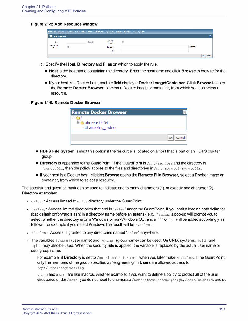
Chapter 21: PoliciesCreating and Configuring VTE Policies
Administration GuideCopyright 2009 - 2020 Thales Group. All rights reserved.
191
Figure 21-5: Add Resource window
c. Specify theHost, Directory and Files on which to apply the rule.n Host is the hostname containing the directory. Enter the hostname and click Browse to browse for the
directory.n If your host is a Docker host, another field displays: Docker Image/Container. Click Browse to open
theRemote Docker Browser to select a Docker image or container, from which you can select aresource.
Figure 21-6: Remote Docker Browser
n HDFS File System, select this option if the resource is located on a host that is part of an HDFS clustergroup.
n Directory is appended to the GuardPoint. If the GuardPoint is /mnt/remote2 and the directory is/remoteDir, then the policy applies to the files and directories in /mnt/remote2/remoteDir.
n If your host is a Docker host, clickingBrowse opens theRemote File Browser, select a Docker image orcontainer, from which to select a resource.
The asterisk and questionmark can be used to indicate one tomany characters (*), or exactly one character (?).Directory examples:
l sales/: Access limited to sales directory under the GuardPoint.
l *sales/: Access limited directories that end in “sales” under the GuardPoint. If you omit a leading path delimiter(back slash or forward slash) in a directory name before an asterisk e.g., *sales, a pop-up will prompt you toselect whether the directory is on aWindows or non-Windows OS, and a ‘/’ or ‘\’will be added accordingly asfollows; for example if you select Windows the result will be *\sales.
l */sales: Access is granted to any directories named "sales" anywhere.
l The variables |uname| (user name) and |gname| (group name) can be used. OnUNIX systems, |uid| and|gid|may also be used. When the security rule is applied, the variable is replaced by the actual user name oruser group name.
For example, if Directory is set to /opt/local/ |gname|, when you later make /opt/local the GuardPoint,only themembers of the group specified as “engineering” inUsers are allowed access to/opt/local/engineering.uname and gname are likemacros. Another example: if you want to define a policy to protect all of the userdirectories under /home, you do not need to enumerate /home/steve, /home/george, /home/Richard, and so

Chapter 21: PoliciesCreating and Configuring VTE Policies
Administration GuideCopyright 2009 - 2020 Thales Group. All rights reserved.
192
on. You only need to define /home/|uname|, When the agent evaluates the policy, it replaces |uname|withthe actual user, so when Steve logs on, the agent evaluates the policy with /home/steve, and they will not beable to access /home/george.When a resource set is defined with a leading asterisk in the directory path, a leading path delimiter (backslash or forward slash) is inserted at the beginning of the string, e.g., */sales results in /*/sales. If the Filefield is left blank, a trailing delimiter and asterisk are added to the path, the asterisk indicating that all filesunder that directory are included in the definition. For example, if a directory path is defined as */sales/* andthe File field is blank, it results in /*/sales/*/*.
o File is the filename and can include variables or patterns.o Include subfolders finds all occurrences of the resource pattern under the GuardPoint and applies policyprotection to them. For example, if the GuardPoint is at a/b and the resource is defined as c/*.txt and Includesubfolders is checked, then every occurrence of *.txt anywhere under the GuardPoint is protected (example:a/b/c/d/*.txt). If Include subfolders is not checked, then only a/b/c/*.txt is protected.
d. Click Ok to add the resources to the Resource Set.
Figure 21-7: Add Resource Set window
NoteYou can also create or select Resource Sets directly, without first creating a policy, by clickingPolicies >Manage Policies > Resource Sets to open theResource Setswindow.
e. Once you have added all resources to your resource set, click Ok. TheSelect Resource Setwindow openswith the new resource set added.
Figure 21-8: Select Resource Set window with new resource set added
f. Select the resource set for this policy and click Select Resource Set. TheEdit Security Rulewindow openswith the resource added (in this example, Protected).
g. Check theExclude option to the right of theResource text-entry field to include all host resources exceptthose resources in the resource set. Uncheck the option to include just the resources in the resource set.

Chapter 21: PoliciesCreating and Configuring VTE Policies
Administration GuideCopyright 2009 - 2020 Thales Group. All rights reserved.
193
Adding a Security Rule User Set to a PolicySpecify theUser criteria. User allows you to specify the users that are permitted or denied GuardPoint access.
To specify all users, leaveUser blank.
1. To define specific users, select User. TheSelect User Setwindow opens.
2. Click Add to create a User Set.
Figure 21-9: Add User Set window
3. Enter aName (for example, User-access) for the User Set and optionally, aDescription.
4. Click Add. The Add User window opens. Youmust specify at least one field.
Figure 21-10: Add User window
l uname
Login name.
l uid (UNIX only)
User identification number
l gid (UNIX only)
User group number, enter only the primary group ID number of the user
l gname
Comma-separated list of group names
l osDomain (Windows only)
Network domain of the user. Multiple domain names, separated by commas, may be entered. Enter the stringlocalhost to configure a generic domain.

Chapter 21: PoliciesCreating and Configuring VTE Policies
Administration GuideCopyright 2009 - 2020 Thales Group. All rights reserved.
194
5. If you click Browse Users, the Add Users page opens:a. Select Agent to select users from a host.b. Select DSM LDAP to select users from all configured LDAP servers.c. To select users from Docker images or containers, use the default Agents selection and select the host
name (FQDN) of the Docker host from the list. Since this a Docker host, another field displays: DockerImage/Container. Click Browse to open the Remote Docker Browser to select a Docker image or containerfrom which to select users.
6. Click Ok to add this user to the User Set.
7. Add as many users to the User Set as needed by repeating the previous steps.
Figure 21-11: Add User Set window
8. Click Ok. TheSelect User Setwindow opens with the new User Set added.
Figure 21-12: Select User Set window
9. Select the User Set for this policy and click Select User Set. TheEdit Security Rulewindow opens with thenew User Set resource added (in this example, User-access).
10. Check theExclude box to the right of theUser text-entry box to include all host users except those users in theUser Set. Uncheck the box to include just the users in the User Set.
11. You can also create or select User Sets directly, without creating a policy, by clickingPolicies > ManagePolicies > User Sets to bring up theUser Setswindow.
Adding a Security Rule Process Set to a PolicySpecify theProcess criteria. A Process Set is a named collection of executable processes that are permitted ordenied access to the GuardPoint data.
l To specify all processes, leaveProcess blank.

Chapter 21: PoliciesCreating and Configuring VTE Policies
Administration GuideCopyright 2009 - 2020 Thales Group. All rights reserved.
195
1. To define specific processes, select Process. TheSelect Process Setwindow opens.
2. Click Add to create a Process Set. TheAdd Process Setwindow opens.
Figure 21-13: Add Process Set window
3. Enter aName (for example View-file) and optional Description.
4. Click Add. The Add Process window opens.
Figure 21-14: Add Process window
l Signature Set
Collection of signed files and/or directory names. Files that are signed confirm software integrity andguarantee that code has not been altered since it was cryptographically signed. If you created a signature setto use with this policy, select the signature set from the scroll-list. Otherwise, youmust first create asignature set.
l Host
Host of the directory or executable and activates theBrowse function.
l Directory
Directory path information. It may be a full path, a relative path, or left blank.
l FileName of the executable. Themore command is used in the example.
5. Click Ok to add this process to the Process Set.
6. If you selected a Docker host, theDocker Image/Container field is displayed, select a Docker image orcontainer, in theDirectory field, click Browse and select a directory from theRemote File Browser, fill in thefile name field as required. Click Ok to return to the Add Process Set page.
7. If you get the pop-up shown below, clickWindows forWindow hosts andNon-Windows for Linux hosts.

Chapter 21: PoliciesCreating and Configuring VTE Policies
Administration GuideCopyright 2009 - 2020 Thales Group. All rights reserved.
196
Figure 21-15: OS Type Pop-Up dialog
8. Repeat the previous steps to add additional process sets,if needed.
9. Click Ok. TheSelect Process Setwindow opens with the new Process Set(s) added.
Figure 21-16: Select Process Set window
10. Select the Process Set for this policy and click Select Process Set. TheEdit Security Rulewindow opens withthe new Process Set added (in this example, View-file).
11. Check theExclude option to the right of theProcess text-entry option to include all host processes except thoseusers in the Process Set. Uncheck the option to include just the processes in the Process Set.
NoteYou can also create or select Process Sets directly, without creating a policy, by clickingPolicies >Manage Policies > Process Sets to bring up theProcess Setswindow.
Adding a Security Rule Time Set to a PolicySpecify theWhen criteria.When enables you to specify whenGuardPoint access is allowed.
NotePolicies for CloudObject Storage do not contain aWhen/Time set.
l To specify all times, i.e. 24-hour access, leaveWhen blank.
To define specific allowable times, selectWhen. TheSelect Time Setwindow opens.

Chapter 21: PoliciesCreating and Configuring VTE Policies
Administration GuideCopyright 2009 - 2020 Thales Group. All rights reserved.
197
1. Click Add to create a Time Set. A Time Set is a named collection of times whenGuardPoint access is permittedor denied. TheAdd Time Setwindow opens.
Figure 21-17: Add Time Set
2. Enter aName (for example Time-1) and optional Description.
3. Click Add. TheAdd Timewindow opens.
Figure 21-18: Add Time window
l Week Day From - To is a range of days of the week during which access is denied or permitted. Values areSunday through Saturday. Enter a day of the week to begin allowing access and a day of the week to stopaccess.
l Date From - To is a range of dates during which access is denied or permitted. Enter a calendar dates tofrom when to begin allowing access and when to stop.
l Start Time - End Time is a range of times during which access is denied or permitted. Enter a start time inthe format hh:mm, select AM/PM, to allow access, and an end time in the format hh:mm, select AM/PM. Thisdefines the exact start time and end time during which access is permitted.
NoteTime is set to the protected host clock, not the GDE Appliance clock.
4. Click Ok to add this time range to the Time Set.
5. Repeat the previous steps to add additional time sets, if needed. Add as many times to the Time Set as needed.

Chapter 21: PoliciesCreating and Configuring VTE Policies
Administration GuideCopyright 2009 - 2020 Thales Group. All rights reserved.
198
Figure 21-19: Add Time Set window
6. Click Ok. TheSelect Time Setwindow opens with the new Time Set added.
7. Select the Time Set for this policy and click Select Time Set. TheEdit Security Rulewindow opens with thenew Time Set resource added (in this example, Time-1).
8. Check theExclude box to the right of theWhen text-entry box to include all times except those times in the TimeSet. Uncheck the box to include just the times in the Time Set.
9. You can also create or select Time Sets directly, without creating a policy, by clickingPolicies > ManagePolicies > Time Sets to bring up the Time Sets window.
Adding a Security Rule Action Set to a PolicyAn action is an attempt to access protected data in someway. Action allows you to specify the type of file and directaction allowed in a GuardPoint. It can be an attempt to read, delete, rename, etc. A Policy provides a wide range ofaccess methods to specify the action required for the security rule. The action is identified, evaluated, and used as afactor in determining whether or not to grant access. Specifying an access method is optional. If you do not specifyone, the Policy defaults to all_ops, or “all operations”.
Any action that starts with d_ applies to directories. Any action that starts with f_ applies to files. Only a few actionsare available for COS (CloudObject Storage) and IDT (In-place Data Transformation - Device) policies.
NoteYou cannot create a policy with ‘all_ops’ and ‘permit’ without ‘apply_key’
Action Description Policy Types
all_ops All operations. User can access the data using any method. This is thedefault if no action is specified. All
d_chg_att Change directory attributes (e.g., chown usr dir1). Standard, LDT
d_chg_sec Change any security property of a directory. Standard, LDT
d_mkdir Make a new directory. Standard, LDT
d_rd View directory contents (e.g., ls dir; cd dir). Standard, LDT, COS
d_rd_att Read the attributes of a directory (e.g., ls -la dir1). Standard, LDT
d_rd_sec View the security properties of a directory. Standard, LDT
Table 21-3: Action Definitions

Chapter 21: PoliciesCreating and Configuring VTE Policies
Administration GuideCopyright 2009 - 2020 Thales Group. All rights reserved.
199
Action Description Policy Types
d_ren Rename a directory (e.g., mv dir1 dir2). Standard, LDT
d_rmdir Delete a directory (e.g., rm -r dir1). Standard, LDT
f_chg_att Change file attributes (e.g., chmod). Standard, LDT
f_chg_sec Change any security property of a file. Standard, LDT
f_cre Create a new file. Standard, LDT
f_link Link to a file (e.g., ln file_name link_name). Standard, LDT
f_rd Read a file. Standard, LDT, COS
f_rd_att Read the attributes of a file (e.g., ls -l file). Standard, LDT
f_rd_sec View the security properties of a file. Standard, LDT
f_ren Rename a file. Standard, LDT
f_rm Remove/delete a file. Standard, LDT, COS
f_wr Write to an existing file. Standard, LDT, COS
f_wr_app Append data to a file. Standard, LDT
key_op
Key operations. This requires 2 key rules. One key is specified in the KeySelection Rules tab and the other in the Data Transformation Rules tab.Key Selection keys are the encryption keys for the current security rule.Data Transformation keys are used to migrate data from an encryptedform to a non-encrypted form or to change the encryption keys used toaccess the data.
Standard, LDT
readRead operations. This method is a collection of the preceding methodsthat are related to reading files, directories, and their attributes. Thismethod comprises f_rd, f_rd_att, f_rd_sec, d_rd, d_rd_attr, and d_rd_sec.
Standard, IDT, LDT
write
Write operations. This method is a collection of the preceding methodsthat are related to writing to files, directories, and their attributes. Thismethod comprises f_wr, f_cre, f_ren, f_rm, f_link, f_chg_attr, f_chg_sec,d_ren, d_chg_att, d_chg_sec, d_mkdir, and d_rmdir.
Standard, IDT, LDT
Table 21-3: Action Definitions (continued)
Specify theAction criteria:
1. Click Select next to the Action field. The Select Action window opens.
2. To specify all actions, select Select All.
3. To specify allowable actions, select the option for that action.
4. When finished, click Select Action. TheAdd Security Rulewindow displays with the allowable actions listedin the Action field.
NoteThe action, key_op, is used for the dataxform policies. If you select key_op and return to the AddPolicy window, the Data Transformation Rule field displays.Youmust add a Data Transformationrule.

Chapter 21: PoliciesCreating and Configuring VTE Policies
Administration GuideCopyright 2009 - 2020 Thales Group. All rights reserved.
200
Adding a Security Rule Effect to a PolicySpecify theEffect for each security rule. Effect is the action that occurs when the attempted access matches all thecriteria in the rule.
NoteIf you are using the policy for data encryption, youmust select Apply Key or the policy will not trigger dataencryption. When it combines with other security rules, it might cause data corruption. Note that if youonly use VTE for access control, you can create a security rule without apply_key and it is valid.
1. Click Select next to the Effect field. TheSelect Effectwindow opens.
Figure 21-20: Select Effect window
l Deny
Denies the access attempt to the resource.
l Permit
Grants the access attempt to the resource.
l Apply Key
Applies an encryption key to data in a GuardPoint. Data copied into the GuardPoint is encrypted with the keyspecified in theKey Selection Rules panel and data that is accessed in the GuardPoint is decrypted usingthe same key.
NoteIf you select Apply Key, youmust also specify the key rules to apply for encrypting anddecrypting the resources.
l Audit
Used in conjunction with permit or deny, audit creates an entry in theMessage Log that describes what isbeing accessed, when it is being accessed, and the security rule being applied.
2. Select desired effects and click Select Effect. The Edit Security Rule window opens with all criteria and theeffects displayed.

Chapter 21: PoliciesCreating and Configuring VTE Policies
Administration GuideCopyright 2009 - 2020 Thales Group. All rights reserved.
201
Figure 21-21: Edit Security Rule window.
3. Click Ok. TheAdd Policywindow opens.
Default Security RuleThe last rule of the policy is called a default security rule or a catchall rule. This rule catches any access attempt that isnot matched by other security rules.
To create a default security rule, leave all criteria fields blank with the exception of Action andEffect on theSecurityRules tab:
l Set Action to all_opsl Set Effect to deny audit
This security rule will match any attempt to access any data on the host. After creating this rule, click Ok in theEditOnline Policywindow.
ThePolicieswindow opens and the policy you just created can be applied to a GuardPoint.
Add Key Selection RulesAfter setting up the Security Rules, set up your Key Selection Rules.
WARNINGBe careful when changing a VTE policy that has already been implemented. Thefollowing practices may cause data corruption in certain scenarios:
* Changing the order of key rules
* Modifying a key rule
* Adding a new key rule
* Deleting a key rule
* Modifying a resource set
* Modifying a resource
1. Click Add in theKey Selection Rules panel at the bottom of the Add Policy window.TheAdd Key Rule window opens.

Chapter 21: PoliciesCreating and Configuring VTE Policies
Administration GuideCopyright 2009 - 2020 Thales Group. All rights reserved.
202
Figure 21-22: Add Key Rule window
2. Click Select and select aResource Set, if desired.A key resource set lets you specify files and directories that are to be encrypted. If you do not specify a resourceset in theKey Selection Rules tab, encryption is applied to the resources specified in theSecurity Rules tab.
3. Select (Current) Key. TheSelect Symmetric Keywindow opens.o For an LDT policy, the current key specifies the key applied to existing data prior to the application of the LDTpolicy. The current key can be a clear key or a non-versioned key. When a policy is applied to protect data,LDT uses the current key to transform the data to the current version of the Transformation Key.
o For aStandard policy, you can enter a key name, or click Select, and theSelect Symmetric Keywindowopens allowing you to select an existing non-versioned key.
o For anEfficient Storage policy, youmust select an AES key with XTS encryption that is KMIP accessible.o For an In-place Data Transformation Device (IDT) policy, youmust select an AES key with XTSencryption.
NoteThe IDT feature is only compatible with VTE v6.3.0 or succeeding versions.
n New Key: Key that replaces the current key. The new key becomes the current key.n Current Key: Key that is currently in use. Note that you can choose clear-key for the current key.
NoteAn IDT policy requires two key rules. However, you can only add one key rule, with two keys, in the UI.Therefore, when you create an IDT policy, GDE converts the key rule into two key rules so that the policycontains the required two key rules. (The API does not have this limitation.)
o For aCloud Object Storage policy, it can only contain one key. Enter a key name, or click Select, and theSelect Symmetric Keywindow opens allowing you to select an existing CBC-CS1 key.
NoteFor COS policies, only encryptionmode CBC-CS1 is supported. CBC is not supported for cloud objectstorage.
4. If this is a key rule for an LDT policy, and you are not excluding files, click Select to open theSelect SymmetricKeywindow, and select a Transformation Key on the Add Key Rule page.The Transformation Key is the versioned key applied to data for the initial transformation from current key andsubsequent rekeying to the next version of Transformation Key.(See "Creating and Adding symmetric keys" on page 162, for more information about LDT versioned keys.)
5. Select Exclusion Rule, if needed.The Exclusion rule allows you to exclude the files or directories, associated with a specific resource set, frombeing transformed.o You cannot exclude files when using a versioned key for the current key or transformation key.

Chapter 21: PoliciesDisplaying Policies
Administration GuideCopyright 2009 - 2020 Thales Group. All rights reserved.
203
o If Exclusion Rule is selected, the Resource field becomesmandatory. GDE Appliance can only exclude filesassociated with a resource set.
o The two keys must be identical. Therefore, when you select the Exclusion Rule, the Transformation Key andCurrent key are automatically set to the same value and the Transformation Key field is hidden.
o User cannot add an Exclusion Rule to any policy that was created in a version prior to v6.4.0 of the GDEAppliance.
o You can clone a policy created in a previous version of GDE Appliance, and thenmodify the cloned policy touse an LDT exclusion key rule policy.
o The Exclusion rule is only compatible VTE v6.2.0 and subsequent versions.o Policies for CloudObject Storage do not support Exclusion rules.
6. Once you’ve selected the keys, click Ok to return to the Edit Policy page.
Displaying PoliciesPolicies are displayed in the Policies window. Policies displayed can be selected for modification or deletion.
1. Log on to theManagement Console as an Administrator with Policy role permissions.
2. Select Policies in themenu bar. The Policies window opens. Configured policies are displayed.
Policy HistoryThe number of times a policy has been changed is displayed in theVersion column of thePolicieswindow. Thisnumber indicates the current revision only. (You cannot use it to roll-back to a previous version. Restore a backup torevert to a previous online policy version.) The version count starts at zero when the online policy is initially createdand increments by one each time it is saved thereafter. Click the policy version number in theVersion column to viewthe version history of a policy.
Figure 21-23: Policy version history
Customize display in the Policy windowl Show Search
Located below thePolicies banner; this opens theSearch panel. You can enter all or part of a policy name and/orlimit the search to policies that are used by a specific type of agent (All or FS). Click Go to display only thosepolicies that match the search criteria. Click Hide Search to conceal theSearch panel.
l Select All

Chapter 21: PoliciesExporting and Importing Policies
Administration GuideCopyright 2009 - 2020 Thales Group. All rights reserved.
204
Selects all the policies that are displayed on the current Web browser page. Select this checkbox to select all thepolicies on the current page at one time. If you have enabled theSelect checkbox for many individual policies, aquick way to deselect them is to enable and then disable theSelect All checkbox.
l View
A scroll-list from which to select themaximum number of policies to display on the current page. Up to 200policies can be displayed on one page. Displays up to the specified number of policies on oneWeb page,regardless of the display number specified in the preferences.Navigation buttons are displayed in thePolicieswindow. Use these buttons to advance between pages. Thebuttons are shown below:
First. Display the first page of policies in the Policy window.
Previous. Display the previous page of policies in the Policy window.
Next. Display the next page of policies in the Policy window.
Last. Display the last page of policies in the Policy window.
Jump to. Advance to the specified page of information. Enter the pagenumber in the text-entry box that is next to this button.
Table 21-4: Policy Window Panel Navigation Buttons
Exporting and Importing PoliciesPolicies can be exported and then imported to the same or another GDE Appliance where you want to replicate thepolicies you’ve already created.
You can choose to export all policies from aGDE Appliance or a specific policy. Policies are generated as xml filesand then compressed and exported to a .tar file with the following naming convention; policy_<YYYY_MM_DD_HHMM>.tar.
NoteEditing the exported policy file is strongly discouraged. This can cause issues with policy enforcement.
When policies are imported to a domain, all the sets (resource sets, user sets, process sets, and time sets) areimported with the following conditions:
l If a set in the imported policy does not exist in the domain that policy is being imported to, then that set is created.
l If a set in the imported policy exists in the domain to which that policy is being imported, then the existing set isoverwritten.
l If a name of a policy being imported conflicts with a name on the domain where it is being imported to, then anumber is appended to the name before it is imported. For example, if the imported policy and a policy in thedomain to which the policy is being imported both contain a policy named ‘secure_file_policy’ then the policy willbe imported as ‘secure_file_policy_1’.

Chapter 21: PoliciesExporting and Importing Policies
Administration GuideCopyright 2009 - 2020 Thales Group. All rights reserved.
205
Export a policyIf you choose to export only some specific policies, then only those Resource sets, Process sets, User sets, andTime sets, and associated action and effects used by those policies are exported.
1. Log on to theManagement Console as an All/Security administrator.
2. Click Policies > Import Export Policies on theManagement Console.
3. On theExport tab, select the policies that you want to export.
4. Click Ok.
5. The policy export file is exported as policy_<YYYY_MM_DD_HHMM>.tar, follow the prompts to save the file to yourpreferred location.
Import a policy1. Log on as an All /Security/Domain and Security administrator.
2. Click Policies > Import Export Policies on theManagement Console.
3. On the Import tab, click Browse to locate the policy file to import.
4. Click Import Policy.
TheGDE Appliance performs pre-import checks on the policies tomake sure that there are no conflicts or missingitems.
l If there are no conflicts or missing keys the import proceeds and the Resource sets, User sets, Process sets, andTime sets are imported. A message confirming that the operation was successful is displayed on the Import tab.
In the event of conflicts or missing keys are detected any the following could occur:
l If the pre-check process finds that the policy keys aremissing, the import is aborted and amessage informing youthat the operation failed is displayed and theMessages text box on the Import tab provides the names of themissing key(s).
l If the policy or policies you import contain Resource sets, User sets, Process sets, or Time sets that have namesthat match existing policies on the GDE Appliance to which they are being imported, or the policy or policiesbeing imported have the same names, theMessages text box will contain amessage listing the imported setsthat conflict with existing sets. You can choose toContinue orAbort the import operation.If you choose to continue, the existing policy will retain it’s name and the imported policy will have ‘_1’ or therelevant number in sequence appended to the name. For example, if you are importing policies to GDE ApplianceB and it has an existing policy called ‘policy1’ and the imported policy has the same name, if you choose tocontinue the import operation, the imported policy will be rename ‘policy1_1’.
l If the pre-check operation detects that there unused sets referenced in the policies, you will be prompted to doeither of the following:o Select Policies & associated sets, whichmeans only sets that are used will be imported.o Select Policies & all sets, whichmeans all sets, regardless of whether they are referenced by the policy ornot will be imported.You can choose toContinue orAbort the import operation.
l If you choosePolicies & all sets and the pre-check finds there are conflicts with exiting sets, you can againchoose to continue or abort the operation.
ThePolicies & all sets option is useful when importing policies from earlier versions of the GDE Appliance. Earlierversions of the GDE Appliance always exported all sets regardless of whether they were used by a policy or not.

Chapter 21: PoliciesExporting and Importing Policies
Administration GuideCopyright 2009 - 2020 Thales Group. All rights reserved.
206

Administration GuideCopyright 2009 - 2020 Thales Group. All rights reserved.
207
Chapter 22: Configuring Hosts and Host GroupsOverview 207Adding Hosts to the GDE Appliance 209Configuring Hosts 215Setting Host Locks 219Sharing a Host 224Host Settings 226Agent Log Settings 231Automatic Renewal of Host Certificates 236Modifying Host Configuration 237Deleting Hosts 239Configuring Host Groups 241
A “protected host” is a computer system onwhich Agents (VTE/VAE/VTS) are installed. The agent on a host mayprotect data on that host, or data on other devices connected to that host.
OverviewThe Hosts page on theManagement Console displays all hosts protected by encryption Agents. GDE ApplianceSecurity Administrators manage hosts via this page; hosts can be added, imported, or deleted.
Refer to theVTE Agent Installation & Configuration Guide for information about installing and configuring a VTE Agent.
Viewing HostsTo see all protected hosts registered with a GDE Appliance:
1. Log on to theManagement Console as an All /Security/Domain and Security administrator.
2. If you log on as type All, click Domains > Switch Domains.a. In theSelected column, click the radio button for the domain you want, then click switch to domain. Skip to
step 4.
3. Navigate toHosts > Hosts.
4. Click Hosts > Hosts. The Hosts page has a table listing names of the protected hosts in the GDE Appliance andthe following details about each protected host:
Column Description
Select Select this checkbox to select the host for deletion. Multiple check boxes can be selected at onetime.
OS Type Values may be Unknown, AIX, HPUX, Linux, Solaris, or Windows. Unknown indicates thatthe host has not been registered or is an unsupported type.
Host Name The name of the host on the GDE Appliance.
Table 22-1: Hosts Window Table Details

Chapter 22: Configuring Hosts and Host GroupsOverview
Administration GuideCopyright 2009 - 2020 Thales Group. All rights reserved.
208
Column Description
VTE/Key Agent This column consists of child columns of check boxes for the VTE Agent and for VAE:- Reg. Allowed—Registration Allowed, indicates that the host can register and be configured to runVTE (File System) Agent software.- Comm. Enabled—Communication Enabled, indicates that a policy can be applied to a host. Reg.Allowedmust be enabled before you can set Comm. Enabled.- Pushing Status—Status for pushing policy and configuration changes to locally assigned hosts.Status is specific to the local GDE Appliance. Run the Management Console on an HA node GDEAppliance to see the push status of the hosts assigned to that server.> Done—Host has the latest policy and configuration changes.> Pending—Update is in progress or is queued for download to the host.> N/A—Local host is disabled or the host is being administered by a different server.This last column is not available for VAE.
One WayCommunication
Indicates that the agent was registered with One-Way Communication enabled between the Agentand the GDE Appliance.
Delete Pending Indicates the status of a request to delete a host.
LDT Enabled Indicates whether the Live Data Transformation (LDT) feature is enabled on the host. If this feature isenabled, Docker support cannot be enabled.
Docker Enabled Indicates whether support for Docker feature is enabled on the host. If this feature is enabled, LDTcannot be enabled.
Description (Optional) Text to help you identify the host.
Sharing Indicates if the host is shared with another domain. The column may have a value of Shared,External, or blank.- Shared indicates that the host is in the current domain and, if the Security Administrator has thecorrect roles, it can be fully configured. The shared host is visible only in the domain with which it isbeing shared.- External indicates that host is administered in another domain. You can assign the host a VTEAgent GuardPoint, but you cannot change the host configuration.- A blank value indicates that the host is not shared.
Table 22-1: Hosts Window Table Details (continued)
The first time you log in, the list of hosts is empty because you have not yet registered any hosts with the GDEAppliance.
The following tasks can be done from this page:l Select All
Selects all hosts displayed on the current page.If you have enabled theSelect check box for many individual hosts, a quick way to cancel the selection is toenable and then disable theSelect All check box.
l View
Specifies the number of hosts to display on the current page. Up to 200 hosts can be displayed on one page.l Search
TheShow Search label located below theHosts banner opens theSearch panel. You can enter a string and/orsearch for a specific type of agent, and click Go to display the hosts that match the search criteria. Click HideSearch to conceal theSearch panel.Navigation buttons are displayed in theHost window. Use these buttons to advance between pages.
l Add

Chapter 22: Configuring Hosts and Host GroupsAdding Hosts to the GDE Appliance
Administration GuideCopyright 2009 - 2020 Thales Group. All rights reserved.
209
Click to create a new host record.l Delete
Enable the check box in theSelect column for one or more hosts and click Delete to remove the selected hostfrom theGDE Appliance database. The agent installation is left intact on the host system and needs to beuninstalled from the host if required.
l Import
Click Import to select a configuration file to addmultiple hosts in a batch operation.
Adding Hosts to the GDE ApplianceYou can add Hosts to a GDE Appliancemanually via theManagement Console, or automatically through the SharedSecret Registrationmethod. You can also add a registration token to the shared secret for multi-factor authentication.Agents on the host are registered with the GDE Appliance using either the Fingerprint Registrationmethod or theShared Secret Registrationmethod. The Shared Secret method is the default.
This section describes the following:
l "Adding hosts using a shared secret" below
l "Adding hosts using a certificate fingerprint" on page 212
l "Adding hosts using a batch file" on page 214
Adding hosts using a shared secretThe Shared Secret method requires a GDE Appliance Administrator to create a registration password for a domain orhost group. This password is shared with the Agent Installer, which uses this password to add and register protectedhosts with the GDE Appliance in a single step. There is no need tomanually add hosts to the GDE Appliance beforeregistering the agent. Adding a host before registering it using the shared secret method, is optional. Multiple protectedhosts can be added with a single shared secret password. As of this release, GDE Appliance Administrators canenforce the shared secret registrationmethod for all hosts, by selecting the option on theWebUI.
TheGDE Appliance only allows hosts that know the secret to register. The agent in turn, knows that it is registeringwith the correct GDE Appliance because it has the same secret. Hosts can be added to a domain, or to a host groupwithin a domain, whichmeans that a shared secret can be defined at the domain level or the host group level.
Add a host to a domain using Shared Secret RegistrationWhen you use the registration secret feature for the first time, theCurrent Registration Secret section does notcontain any information. If there is an existing shared secret, thenShow Registration Shared Secret displays. Youcan display the secret criteria, if needed.
The first step is for theSecurity Administrator to create a registration shared secret
1. Log on an administrator with Host role permissions.
2. Switch to the domain to which you want to add the host.
3. Select Hosts > Registration Shared Secret in themenu bar. The Registration Shared Secret window opens.
4. Enter the following information in theCreate new Registration Shared Secret section:a. Registration Shared Secret creation method—The same constraints that apply to password creation,
namely uppercase letters, numbers, and special characters required, apply to the shared secret creation.n Manual—This is the default method. Select this to create the shared secret yourself.n Generate—Select this option to get an automatically generated password.

Chapter 22: Configuring Hosts and Host GroupsAdding Hosts to the GDE Appliance
Administration GuideCopyright 2009 - 2020 Thales Group. All rights reserved.
210
b. Validity Date—Enter a date, or select a date by clicking the calendar icon. The datemust be in the formatMM/DD/YY.
c. Require that hosts are added first—Optional. If you select this option, you need to first add the host to theGDE Appliance database with theRegistration Allowed check box enabled before you install and configurethe agent.
d. Enforce shared secret during host registration—Optional. If you select this option, hostsmust registerwith the GDE Appliance using the shared secret. Any attempt to register a host using the fingerprint methodwill fail.
5. Click Ok.
6. To remove an existing shared secret, click Expire Registration Shared Secret. The expiration date turns red toindicate that the shared secret is no longer valid.
The Account Lockout settings defined inGeneral Preferences > Password > Account Lockout also apply to theregistration shared secret, see "Account Lockout" on page 44 for more information about these settings.
Creating and Using a Registration TokenThe shared secret is shared by all of the hosts in a specific domain, or a host group. If the shared secret is somehowcompromised, it must be regenerated (or re-entered) and this could disrupt many other agent hosts. Therefore, theGDE Appliance now provides a second authentication credential, a token, that is tied to a specific host or a host group.Only that host/hostgroup can use that token to register to a GDE domain. This provides two-factor authentication foragent registration.
NoteThis feature is only compatible with VTE v6.3.0 (or greater).
To create a Registration Token:
1. Log on as an administrator with Host role permissions.
2. Switch to the domain to which you want to add the token.
3. Select Hosts > Registration Shared Secret > Registration Shared Secret in themenu bar. The RegistrationShared Secret window opens.
4. Select the option forRegistration Token Enabled.
5. Enter the host name for the host to which to assign the token.l If you want to assign the token to a group of hosts, use a wild card. (For example: *.ca.amazon.com)
6. Set the expiration date and time.
7. Click Generate Registration Token. TheGDE Appliance generates a token and downloads it to your downloadsdrive.
8. Click OK to save the configuration.
9. Open the token file with a text editor and save it as a text file called dsm_reg_token.
10. Send the token to the VTE administrator. They must install the token on the agent system prior to registrationwith the GDE Appliance.
11. To install, the VTE adminmust copy the file into the following location:l For Linux/AIX systems: /etc/vormetric/dsm_reg_token
l ForWindows systems: C:\Windows\Temp\Vormetric\dsm_reg_token

Chapter 22: Configuring Hosts and Host GroupsAdding Hosts to the GDE Appliance
Administration GuideCopyright 2009 - 2020 Thales Group. All rights reserved.
211
When the agent runs the registration code, the token is read and submitted as part of the registration payload.
12. When finished, click OK in the Registration Shared Secret Window.
Register the host on the GDE ApplianceAfter the agent has been installed, you will be prompted to register the host to the GDE Appliance:.
NoteThe exact sequence of steps may differ from agent to agent, for details about how to install specific agenttypes, refer to theVTE Agent Installation & Configuration Guide.
1. You will be prompted to select amethod to register the host. Select the shared secret option to register the host.This is the default option.
2. Enter the following information when prompted:a. What is the registration shared secret?
Enter the shared secret of the domain to which you the host is to be added. Or enter the shared secret of thehost group to which the host is to be added.
WARNINGBe sure to enter the shared secret correctly, the prompt will not display any enteredtext, nor does the prompt move until you press enter. If the shared secret was enteredincorrectly, an error message is displayed, saying that the certificate signing wasunsuccessful. If you exceed the number of tries defined in the Maximum Number ofLogin Tries setting on the Password Preferences page, you will be locked out of thesystem for a period defined in the User Lockout Time setting on the same page.
b. Domain nameEnter the name of the domain to which the host is to be added.
c. Host Group (Optional)If the host is to be added to a host group, enter the name of the host group to which it is to be added, else clickenter or next and continue to the next step.
d. Host description (Optional)Enter a description of the host to be registered.
3. Confirm the information is correct and proceed with the registration.
4. Open theManagement Console on the GDE Appliance, switch to the domain where the host has been added, thehost should be listed in the hosts table.If the host was added to a host group, select Hosts > Host Groups and click the host group where the host hasbeen added, the host should be visible in the table.
Create a Registration Shared Secret for a HostGroupWhen adding a host to a host group in a domain, the Security Administrator must first create a registration sharedsecret:
1. Log on an administrator with Host role permissions.
2. Switch to the domain to which you want to add the host.
3. Select Hosts > Host Groups in themenu bar. The Host Groups window opens.

Chapter 22: Configuring Hosts and Host GroupsAdding Hosts to the GDE Appliance
Administration GuideCopyright 2009 - 2020 Thales Group. All rights reserved.
212
4. Click a host group name or create a host group where the host is to be added and click the host group name. TheEdit Host Group page is displayed. Click theRegistration Shared Secret tab.
Figure 22-1: Host Group Registration Shared Secret window
The remaining steps to create a registration shared secret for a hostgroup are the same as "Add a host to a domainusing Shared Secret Registration" on page 209.
Adding hosts using a certificate fingerprintThe Fingerprint Registrationmethod requires you to first add the host name, or its IP address, to the GDE Appliancefrom theManagement Console. Once the host is added to the GDE Appliance, you can register the host from theAgent Installer on the host.
To add hosts to the GDE Appliance:
1. Determine themanner in which you want to address the host. That is, FQDN, host name, or IP number.o If FQDN, verify that DNS is configured and working on theGDE Appliance.o If host name, use the host CLI command to link IP numbers with host names, or edit /etc/hosts directly.
2. Log on to theManagement Console as a Security administrator withHost role permissions, or a Domain andSecurity, or All administrator.
3. Switch to the domain where you will add the host.
4. Select Hosts > Hosts in themenu bar. The Hosts window opens.
Figure 22-2: Hosts window
5. Click Add. The Add Host window opens.

Chapter 22: Configuring Hosts and Host GroupsAdding Hosts to the GDE Appliance
Administration GuideCopyright 2009 - 2020 Thales Group. All rights reserved.
213
Figure 22-3: Add Host window
6. Enter the following information:a. Enter the IP address, host name or FQDN (253 characters max.).
NoteHost names that include an underscore are rejected by theManagement Console.Host names that have a dot (‘.’) appended to them, prevents the agent configuration log files from beinguploaded to the GDE Appliance. However, if your hostname does contain a dot appended to it, then youmust re-register that host using the host IP address and then upload the log files.
b. Select a Password Creation Method. This is the password you use to unlock aGuardPoint when there is noserver connection.
o Generate (challenge-response)Dynamic password. Each time a host password is required, the Security Administrator requests a newpassword from aGDE Appliance Administrator.
o ManualStatic password that is entered each time a host password is required. SelectManual, then enter and re-enterthe password in thePassword/Confirm Password fields.
c. Select to automatically assign the host to a GDE Appliance during host registration. Automatic hostassignment is a load-balancing function in an HA cluster. If servers in the HA cluster are physicallydistributed over great distances, youmay not want to use this option because hosts can be assigned todistant servers with slow connections. By default, hosts are assigned to the initial GDE Appliance when theyare added. If you leave it unchecked, you can specify the server to explicitly assign the host later in theHostsfor High Availability Serverwindow.
d. Enter text that helps you to identify the host in the description field. Themaximum number of characters is256.
e. Select the agents that will run on the host system. Depending on your license, your choices are FS (VTE), andKey (VAE). Youmust select the agent before you can register that agent with the GDE Appliance. Only theagents you have a license for will display here. For DDC remediation, select FS.
f. Select Communication Enabled to enable communication between theGDE Appliance and the agent. Thiscan also be done later by going to the Edit Host page.
7. Click Ok.
8. The host administrator (with root access) installs the agent software on the host.You canmanually configure agent certificates later if the certificate generation and exchange phase of agentsoftware installation fails.

Chapter 22: Configuring Hosts and Host GroupsAdding Hosts to the GDE Appliance
Administration GuideCopyright 2009 - 2020 Thales Group. All rights reserved.
214
Adding hosts using a batch fileYou can addmultiple hosts to the GDE Appliance simultaneously. After they are added to the GDE Appliance, you caninstall and register the agents that run on those hosts.
Notesl This batch process does not reduce the time it takes to add individual hosts to the GDE Appliance. Itonly makes it easier to addmany hosts by reducing key strokes and permitting unattendedoperation.
l The batch input file is not verified as it is read. If there are errors in the batch input file, such asmalformed passwords or inappropriate characters, this operation can fail and hang and no hosts willbe added.
The lines in a batch file are individual host definitions that follow an identical format. Each line is a comma-separatedlist consisting of six fields. If you want to include a comma as part of the field value, enclose the whole field in double-quotes (“). Do not enclose other special characters, such as the colon (:), in double-quotes.
The format of a batch file line is:
hostname,description,password,allow_fs_agent
where:l Hostname
An alphanumeric string that represents the host name or FQDN of the host being added. This is the networkidentity of the host.
NoteDo not enter a host name that contains the underscore character (_). Host names that include theunderscore character are rejected by theManagement Console.
l Description
A text string that describes the host.l Password
This is not a regular login or user password. This is the host password to be used by the host system to decryptcached keys when theGDE Appliance is not accessible. The host must also be configured withCached onHost keys.
l Allow_fs_agent
A boolean string that is either “yes” or “no” to enable or disable VTE Agent registration.An example batch file is shown below:
host1,This is host 1,onlyMe78,yes,yes
host2,This is host 2,bobsNum1,yes,yes
host3,This is host 3,goOd4U678,no,yes
host4,This is host 4,some1Else,yes,no
host5,This is host 5,qwerty123,no,yes
host6,This is host 6,ooPB2AUoo,no,yes
To add hosts using a batch file:
1. Create the batch file as described above.
2. Log on an administrator with Host role permissions.
3. Select Hosts > Hosts in themenu bar. TheHostswindow opens.

Chapter 22: Configuring Hosts and Host GroupsConfiguring Hosts
Administration GuideCopyright 2009 - 2020 Thales Group. All rights reserved.
215
4. Click Import. The Import Hosts window opens.
5. Click Browse next to the Import Hosts File text-entry box.
6. Navigate to, and select, the batch file from the Choose File to Upload window.
7. Click Open.
8. Click Ok in the Import Hosts window.Wait until the followingmessage is displayed: The operation is successful.
9. Click Hosts on theManagement Consolemenu bar to display the Hosts window and the newly added hosts.
Agent software can now be installed on these systems and the agents can be registered with the GDE Appliance.
Configuring HostsAfter adding and registering hosts with the GDE Appliance, you need to configure the new host.
1. Select Hosts > Hosts in themenu bar. TheHostswindow opens.
2. Click the link in theHost Name column of the host you want to modify. TheEdit Host window opens to theGeneral tab.
NoteIf theEdit Hostwindow displays only two tabs, General andGuardPoints, it means you are working witha shared host. Check the host status in theSharing column of the Hosts window. If you want to domorethan add or removeGuardPoints, switch to the domain in which the host was created.
The following host attributes are displayed, some of the fields can bemodified:l Name
FQDN of the hostl Description
Add ormodify a description of the host.l OS Type
Operating system on the hostl Communication Port
You can change the port number used to exchange policy enforcement data between theGDE Appliance and theVTE (FS) Agent. Generally, you change the port number only when the default port number is already in use or ifyour firewall requires a different port number.If you change the port number, click Ok. The configuration change is downloaded to the VTE Agent host after theinterval set by theUpdate Host Frequency parameter.After the update is downloaded, youmust manually restart the VTE Agent. Execute one of the followingcommands on the VTE Agent host to restart the VTE Agent:o On Linux, Solaris, and AIX:
# /etc/init.d/secfs restart
o OnRedhat 7.2:# /etc/vormetric/secfs restart
o OnHP-UX:# /sbin/init.d/secfs restart

Chapter 22: Configuring Hosts and Host GroupsConfiguring Hosts
Administration GuideCopyright 2009 - 2020 Thales Group. All rights reserved.
216
NoteInformation about UNIX agents applies to earlier versions of those agents. As of v6.0, UNIX agents suchas Solaris and HP-UX are EOL. AIX is still supported.
Choose the type of license that will run on this host. Options are Perpetual, Term, and Hourly.l FS Agent Locked
Locks the contents of the VTE Agent directories on the host. See "Setting Host Locks" on page 219 for about thissetting.
System LockedApplies an internal policy to the host to lock host system directories, like /var, /bin, /etc. This can be selectedonly if FS Agent Locked is enabled.
l Support Challenge & Response
Indicates whether this feature is enabled on the host. It becomes enabled when the VTE Agent running on thehost registers with the GDE Appliance.
l Password Creation Method
If you switch the passwordmethod fromManual toGenerate, regenerate the password. Select RegeneratePassword and click Apply. A new generated password is downloaded to the host.If you switch the passwordmethod fromGenerate toManual, enter a new password in thePassword andConfirm Password boxes.By default, thePassword andConfirm Password text-entry boxes display dots. The dots are just graphicplaceholders and do not indicate that a password had been entered. Youmust enter a password in both text-entryboxes or theManual passwordmethod will not be applied to the host.
NoteIf you select the generate password creationmethod for an agent that does not support the challenge-response feature, an ERROR-level audit message is generated and entered in the log after the agentregisters with the GDE Appliance, plus a red warningmessage is displayed on theEdit Hostwindow forthe host. In effect, a randomly generated password is created and downloaded to the host system;however, the vmsec challenge command is not available on the host system so a user cannot display achallenge string. The solution is to change the host configuration fromGenerate toManual andmanuallyenter the host password.
l Regenerate PasswordPasswordmethod to use to unlock the agent. The host user may be prompted to supply a password to decryptencrypted data when there is no network connection between the host and the GDE Appliance. Themethods areGenerate (challenge-response) andManual (static password). WhenGenerate is selected, the host user mustrequest a new password from aGDE Appliance administrator each time a host password is required.Password/Confirm Password—Displayed whenPassword Creation Method is set toManual, enter and re-enter the password to use to unlock aGuardPoint when there is no server connection.
l Docker EnabledSelect this check box to enable docker support.
NoteIf you selected the option to enable Docker support during the agent registration procedure, this check boxwill display as selected, indicating that this feature has been enabled. Refer to theVTE Agent Installationand Configuration Guide for more information.

Chapter 22: Configuring Hosts and Host GroupsConfiguring Hosts
Administration GuideCopyright 2009 - 2020 Thales Group. All rights reserved.
217
Once Docker support is enabled, it cannot be disabled. TheDocker Enabled check box is selectable only if yourVTE agent license includes this feature. If your VTE Agent (FS Agent) license includes Live Data Transformation(LDT) and you choose to enable Docker support on a host, then the LDT check box is disabled, as the twofeatures cannot coexist. Similarly if a host has the Live Data Transformation check box enabled then theDocker Enabled check box is disabled. See "Enabling Docker Support" below for steps to enable this feature.
l Live Data TransformationSelect this check box to enable Live Data Transformation (LDT) on the host.
NoteIf you selected the option to enable LDT support during the agent registration procedure, this check boxwill display as selected, indicating that this feature has already been enabled. Refer to theVTE AgentInstallation and Configuration Guide for more information.
Once LDT support is enabled, it cannot be disabled. The Live Data Transformation check box is selectableonly if your VTE Agent (FS Agent) license includes this feature. If your VTE license includes Docker support andyou choose to enable LDT, then theDocker Enabled check box is disabled as the two features cannot coexist.Similarly, if a host has theDocker Enabled check box enabled then the Live Data Transformation check boxis disabled. See "Enabling Live Data Transformation" on the next page for steps to enable this feature.
l Secure Start GuardPoint
Select this option if you want to create a Secure Start GuardPoint for Active Directory or MSSQL directories. Thisfeature is only supported on hosts runningWindows OS. Refer to theVTE Agent Installation & ConfigurationGuide for more information about using Secure Start GuardPoints.
NoteTheDocker and Live Data Transformation options are only displayed if you have the relevant license.
3. Once your host is registered with the GDE Appliance, you can start protecting your data by creating GuardPoints,see Chapter 23: "Managing GuardPoints" on page 253 for more about creating andmanaging GuardPoints.
4. TheSharing tab lets you share the GuardPoints on the host with Security Administrators in other domains, see"Sharing a Host" on page 224.
5. Use theHost Settings tab to set authentication options for applications running on the host. See "Host Settings"on page 226 for more information.
6. TheChallenge Response tab allows aGDE Appliance Security Administrator to generate a temporarypassphrase to give to a host administrator to decrypt data on the host when there is no connection to the GDEAppliance.
7. Use the agent log tabs (FS Agent Log, Key Agent Log, Docker Log) to define log settings. See "Agent LogSettings" on page 231 for more information.
8. You can optionally add the host to a host group using theMember tab, see "Configuring Host Groups" onpage 241.
Enabling Docker SupportData protection policies can be set up for Docker images and Docker containers. In addition to data encryption, theGDE Appliance also provides Docker container-level access control and container-level audit logging. GDE ApplianceSecurity Administrators can create GuardPoints on Docker images and containers via theManagement Console.
Docker support is available on the following platforms:
l Docker Host: RHEL 7.0, 7.1, and 7.2
l Docker containers: heterogeneous container support, including but not limited to, RHEL, CentOS, Ubuntu, SUSE

Chapter 22: Configuring Hosts and Host GroupsConfiguring Hosts
Administration GuideCopyright 2009 - 2020 Thales Group. All rights reserved.
218
l Docker storage driver: devicemapper
In order to use the Docker support feature on a host, youmust have the following:
l VTE Agent 6.0 license with Docker support
l A host with Docker configured and running
l VTE Agent version 6.0 installed on the Docker host
Refer to theVTE Agent Installation & Configuration Guide for information about installing and configuring a VTE Agent.
After installing the VTE Agent on the Docker host and registering it with GDE Appliance, youmust enable Dockersupport on the GDE Appliance:
1. Log on to theManagement Console as an All, Domain and Security, or Security administrator.
2. On themainmenu bar of theManagement Console, click Hosts.
3. On the Hosts page, click the name of the Docker host in theHost Name column, the Edit Host page opens.
4. In theHost Information panel of the Edit Host page, select theDocker Enabled check box.
Once you have enabled Docker on a host, you cannot disable it. To disable the feature, youmust first unregister andthen delete the host and then re-register the host, without enabling the feature. This will let you reclaim the license foruse on another host.
Next, edit theHost Settings:
1. Log on to theManagement Console as an All, Domain and Security, or Security administrator.
2. On themainmenu bar of theManagement Console, click Hosts.
3. On the Hosts page, click the name of the Docker host in theHost Name column, the Edit Host page opens.
4. Click theHost Settings tab.l If you are using a Docker engine version earlier than version 1.12.1, add the following entry to theHost Settings
text box:|authenticator|/usr/bin/docker
l If you are using a Docker engine version 1.12.1 or later, add the following entry to theHost Settings text box|authenticator|/usr/bin/dockerd
For details about creating Docker GuardPoints, see Chapter 23: "Managing GuardPoints" on page 253.
Enabling Live Data TransformationThe Live Data Transformation (LDT) feature enables GDE Appliance Security Administrators to encrypt or rekeyGuardPoint data without blocking user or application access to that data.
In standard VTE deployments, access to data is blocked during initial encryption or rekeying of data. With Live DataTransformation (LDT), encryption and rekeying of data takes place in the background, without disrupting user orapplication access.
In order to use LDT youmust have the following:
l VTE Agent 6.0 license with LDT.
l VTE Agent version 6.0 installed on a host. Refer to theVTE Agent Installation & Configuration Guide forinformation about installing and configuring a VTE Agent.Refer to the Live Data Transformation Guide and theVDS Compatibility Matrix for information aboutimplementing LDT and the supported platforms.

Chapter 22: Configuring Hosts and Host GroupsSetting Host Locks
Administration GuideCopyright 2009 - 2020 Thales Group. All rights reserved.
219
NoteThe LDT feature uses ‘versioned keys', which automatically expire and rotate, as defined by the key'ssettings. The key rotation and key expiration occur in the background, and it is possible that a GDEAppliance backupmay not contain the latest versions of the rotated keys. In the event of a GDE Appliancefailure, all keys that were automatically rotated after the last backup would be lost, making all dataencrypted with those keys unusable or unrecoverable. Therefore, we recommend that the LDT feature beused in a high availability deployment.
If LDT must be used in a single GDE Appliance configuration, we recommend that you specify ‘CachedOnHost’ for all keys that are created, and to set the password creationmethod to ‘Manual’ for all hosts. Inthe event that the standaloneGDE Appliance fails and is unavailable, access to the data on the host is stillavailable by entering the known passphrase, and the data is available as the encryption keys are cachedon the host.
After installing the VTE Agent on a host and registering it with GDE Appliance, youmust enable LDT support:
1. Log on to theManagement Console as an All, Domain and Security, or Security administrator.
2. On themainmenu bar of theManagement Console, click Hosts.
3. On the Hosts page, click the name of the host on which you want to enable the feature in theHost Name column,the Edit Host page displays.
4. In theHost Information panel of the Edit Host page, select the Live Data Transformation Enabled check box.
Once Live Data Transformation has been enabled, it cannot be disabled. To remove the feature, youmust migrateexisting data protected under LDT policies, unregister and delete the host and then re-register the host, withoutenabling the feature. This will let you reclaim the license for use on another host. See "Deleting Hosts" on page 239 formore information.
For details about creating LDT GuardPoints see, Chapter 23: "Managing GuardPoints" on page 253.
For details about how LDT works, guidelines and best practices for using the feature, refer to the Live DataTransformation Guide.
Setting Host LocksFS Agent Locked andSystem Locked are two options used to protect the VTE Agent and certain system files. VTEAgent protection includes preventing some changes to the VTE Agent installation directory and preventing theunauthorized termination of VTE Agent processes. These options appear inGeneral tab of the Edit Host and EditHost Group windows and are disabled by default.
NoteYoumight not be able to upgrade or delete agent software if you do not disable the locks first.- Disable FS Agent Locked before updating or deleting agent software on the host system.- Disable FS Agent Locked before deleting the host record from theManagement Console.- DisableSystem Locked before updating, deleting, or modifying protected system files.
To apply locks:
1. Check that no one is currently in or accessing the Agent installation directories; otherwise, the GDE Appliancemay be unable to lock the Agent software.
2. Log on an administrator with Host role permissions.
3. To set the locks on an individual host:a. Select Hosts > Hosts in themenu bar.

Chapter 22: Configuring Hosts and Host GroupsSetting Host Locks
Administration GuideCopyright 2009 - 2020 Thales Group. All rights reserved.
220
The Hosts window opens.b. Click a host name in theHost Name column.
The Edit Host window opens to theGeneral tab.c. To protect VTE Agent files frommodification and deletion, enable the FS Agent Locked check box.d. To protect a set of system files frommodification and deletion, enable theHost > System Locked check
box.System Locked is automatically enabled when FS Agent Locked is enabled. You can enable and disableSystem Locked only when FS Agent Locked is enabled.
e. Select Ok to finalize the changes.
To set locks on hosts in a host group:
1. Select Hosts > Host Groups in themenu bar.The Host Groups window opens.
2. Click a host group in theName column.TheEdit Host Groupwindow opens to theGeneral tab.
3. To protect VTE Agent files frommodification and deletion, enable the FS Agent Locked check box.
4. To protect a set of system files frommodification and deletion, select Host > System Locked.System Locked is automatically enabled when FS Agent Locked is enabled. You can enable and disableSystem Locked only when FS Agent Locked is enabled.
5. Select Ok to finalize the changes.
6. (Optional) As a host administrator with root permissions, verify that the locks have been applied to the agent.a. Log onto the host (agent) system.b. Execute the secfsd commandwith the lockstat argument:
# secfsd -status lockstat
FS Agent Lock: true
System Lock: true
#
NoteSometimes there is a discrepancy between what the GDE Appliance reports as the VTE Agentconfiguration and the actual VTE Agent configuration. This may be due to the time delay between loguploads to the GDE Appliance, or because aGuardPoint is in use when the lock is applied.
If the locks are enabled and theGDE Appliance cannot administer the host, such as can occur after changingauthentication credentials or removing the certificate fingerprint, the host administrator must unlock the host manually.The certificate fingerprint can be removed if theRegistration Allowed check box on theGeneral tab of the Edit Hostpage, is not selected
To unlock the host manually, boot the host into single-user mode and edit the./secfs/.sec/conf/configuration/secfs_config file.Set both coreguard_locked and system_locked to false. Save the file. Boot the system intomulti-user mode. Youshould now be able to administer the host again.OnWindows systems, boot in safemode, rename C:\Windows\system32\drivers\vmmgmt.sys and.\drivers\vmfiltr.sys to something else, then boot in regular mode.
The host administrator must inform the Security Administrator of changes to the system hierarchy.

Chapter 22: Configuring Hosts and Host GroupsSetting Host Locks
Administration GuideCopyright 2009 - 2020 Thales Group. All rights reserved.
221
l Example 1: The host system administrator can request to have the locks temporarily disabled to do someadministrative functions.
l Example 2: The host system administrator can remove directories and files, then, later when the lock isreapplied, the GDE Appliance is protecting non-existent data.Another common administrative issue pertains tomounted GuardPoints. The host system administrator canremove or unmount an unlocked, non-automounted GuardPoint. TheGDE ApplianceManagement Consoleinterface is not aware of this change and does not issue a warning when you reapply the lock to the now non-existent mounted GuardPoint.
l To recover an unmounted GuardPoint:a. Disable the GuardPoint for the file system in theManagement Console.b. Mount the file system on the host.c. Enable the GuardPoint for the file system.
FS Agent lockedFS Agent Locked locks the contents of the VTE Agent directories on the host. These directories are /<installroot>/agent/secfs and /<install root>/agent/vmd.
Files in these directories cannot bemodified or removed when FS Agent Locked is enabled; however, the GDEAppliance can still propagate updates to the host system.
When FS Agent Locked is enabled:l System Locked is automatically enabledl Certificates are exchanged and the host is bound to the GDE Appliance
l The VTE Agent installation directory cannot be deleted or overwritten
l The VTE Agent services cannot be stopped
l The VTE Agent GuardPoints cannot be forcefully unmounted
When FS Agent Locked is disabled:l System Locked is automatically disabledl The VTE Agent software on the host is not protected
NoteDo not unregister or delete the VTE Agent while locks are applied. The locks stay in effect after the agentis unregistered and, without agent credentials, the GDE Appliance cannot administer that Agent and itcannot disable the locks. Youmust boot the host into single-user mode andmanually modify the agentconfiguration to disable the locks.
On Linux systems, all operations are permitted in the following directory when FS Agent Locked is enabled./<install root>/agent/secfs/tmp
On Linux systems, the following directories cannot be removed or renamed, and directory and file creation will failwhen FS Agent Locked is enabled.
/<install root>/agent/secfs/bin
/<install root>/agent/vmd
On Linux systems, file creations and other operations will work for the following directory, but the directory cannot beremoved or renamedwhen FS Agent Locked is enabled.
/<install root>/agent/secfs/

Chapter 22: Configuring Hosts and Host GroupsSetting Host Locks
Administration GuideCopyright 2009 - 2020 Thales Group. All rights reserved.
222
OnAIX systems, the contents of the following directories cannot be changed or moved when FS Agent Locked isenabled.
/<install root>/agent/vmd
OnAIX systems, the contents of the following files and directories can bemodified, but not removed or renamedwhenFS Agent Locked is enabled.
/<install root>/agent/secfs/
/<install root>/agent/secfs/tmp
OnWindows systems, when FS Agent Locked is enabled, the following folder cannot bemoved and its contentscannot bemodified:
C:\Program Files\Vormetric\DataSecurityExpert\Agent\secfs\sec
Also, the VTE Agent entries in the registry cannot bemodified or deleted when FS Agent Locked is enabled on aWindows system.
System lockedSystem Locked applies an internal policy to the host to lock host system directories, such as /var, /bin, /etc, andso on. When you enable FS Agent Locked, System Locked is automatically enabled.
NoteTo upgrade or install third-party software, add new applications, open an SSH session remotely, or modifysystem directories, youmust disableSystem Locked.
Note(Windows only) Verify that the volume letter and the path for theWindows system are correct beforeproceeding. WhenWindows VTE Agent software is installed, the volume letter defaults to “C:” Theexecutables in theHost Settings tabmay be on a different volume or in a different folder. If the volume orpath information is incorrect, the GDE Appliance cannot sign the applications, and it will be unable to applyFS Agent Locked andSystem Locked.
WhenSystem Locked is enabled:l Operating system directories on the host are protected.
l Microsoft Update cannot be run onWindows systems to protect the host. Microsoft update and other installation-related executables are specifically blocked. Executables like wuacuclt.exe and msiexec.exe cannot be run.
l The installation utility checks if System Locked is enabled on the host system. If it is, the utility abortsinstallation and displays amessage telling you to "unlock system before running install/updateprogram". Other third-party installation utilities do not check if System Locked is enabled and are not preventedfrom installing software.
l New file or directory creation inside a protected directory is not allowed.
WhenSystem Locked is disabled:l The internal policy is disabled.
l FS Agent Locked remains enabled.l You can install or update system software.
The following files, directories, and subdirectories are, by default, automatically protected whenSystem Locked isenabled. NB: Asterisks (*) indicate patternmatching.

Chapter 22: Configuring Hosts and Host GroupsSetting Host Locks
Administration GuideCopyright 2009 - 2020 Thales Group. All rights reserved.
223
On Linux systems, the following files and the contents of the following directories cannot be changed or moved whenSystem Locked is enabled.
l /etc/pam.dl /etc/rc*l /etc/securityl /usr/lib/security
On Linux systems, the contents of the following files and directories can bemodified, but not removed or renamedwhenSystem Locked is enabled.
l /etcl /etc/init.d/secfsl /usrl /usr/bin/vmdl /usr/bin/vmsecl /usr/bin/secfsdl /usr/bin/dataxforml /usr/libl /usr/lib/*pam*l /usr/lib/securityl /var/log/vormetric
OnSolaris systems, the following files and directories cannot be created, edited, or deleted, whenSystem Locked isapplied.
l /usr/lib/fs*l /usr/ker*l /usr/pla*l /usr/lib/securi*l /etc/rc*l /etc/ns*l /etc/vfs*l /etc/init.d/secfsl /etc/systeml /ker*l /pl*l /sbin
OnAIX systems, the following files and the contents of the following directories cannot be changed or moved whenSystem Locked is enabled.
l /etc/rc.dl /etc/securityl /usr/lib/securityl /sbin/helpers/mount_secfs
OnAIX systems, the contents of the following files and directories can bemodified, but not removed or renamedwhenSystem Locked is enabled.
l /var/log/vormetric
OnHP-UX systems, the following files and the contents of the following directories cannot be changed or moved whenSystem Locked is enabled:
l /sbin/rc[0-4].dl /sbin/init.dl /usr/lib/securityl /etc/pam.conf

Chapter 22: Configuring Hosts and Host GroupsSharing a Host
Administration GuideCopyright 2009 - 2020 Thales Group. All rights reserved.
224
l /etcl /usrl /sbinl /sbin/rcl /etc/inittabl /usr/lib
OnHP-UX systems, the contents of the following files and directories should not bemodified whenSystem Locked isenabled:
l /sbin/fs/secfs2l /usr/bin/secfsl /usr/bin/vmdl /usr/bin/vmsecl /usr/bin/secfsdl /usr/bin/dataxform
WhenSystem Locked is applied, a protected file or path cannot be renamed or deleted; however, if it is a directory,other files may be added to it. For example, /etc cannot be deleted nor renamed, though you can add files to it. A filethat cannot bemodified cannot be opened and edited in any way.
OnWindows systems, files with the following extensions in theWindows OS installation folder (for instance:\Windows, \WinNT, and so on) cannot bemoved or modified whenSystem Locked is enabled:
l .exel .dlll .sysl .cmdl .com
Setting locks on Docker hostsThe FS Agent Locked andSystem Locked options are applicable to Docker host systems but, they are notapplicable to Docker images and containers. Files and directories that are locked on the Docker host using theseoptions remain locked, even if they are indirectly accessed through a Docker image or container.
Sharing a HostSecurity Administrators in other domains may administer GuardPoints on a locally configured host if sharing isenabled. This feature is used to allow Security Administrators in other domains tomanage a host or host group in thatdomain. The domains that are allowed to administer the local host are set and displayed in theSharing tab of theHosts window.
The shared/not shared status of a host is indicated on several Management Console windows:
l Hosts and Host Groups windows
l Edit Hosts window, Sharing tabl Edit Hosts window, GuardPoints tab—indicated by an obscuredSelect check box and italicized host policy
name
l A host that is not configured for sharing displays a blank in theSharing status field in the Hosts window.l A shared host that is being accessed in the same domain in which it was created has a fully functional interface
and displays Sharing in theSharing status field. All the tabs in the Edit Host window are displayed and can beused to configure the host.

Chapter 22: Configuring Hosts and Host GroupsSharing a Host
Administration GuideCopyright 2009 - 2020 Thales Group. All rights reserved.
225
l A shared host that is being accessed by a Security Administrator in a different domain than the domain in which itwas created has a partially functional interface and displays a sharing status of External. Only theGeneral andGuardPoints tabs in the Edit Host window are displayed and they are used to add and removeGuardPoints.
The Edit Host window in theManagement Console normally displays tabs that are used to configure VTE Agents,agent logs, and set other host parameters. The Edit Host window for a shared host displays only theGeneral andGuardPoints tabs
The current Security Administrator domain will be displayed in the top-right corner of theManagement Consolewindow. The domain of a shared VTE Agent is displayed in theGuardPoints tab of the Hosts and Edit Hostswindows. ThreeGuardPoints were applied in datadomain1 and the other in datadomain2. TheSelect check boxes forGuardPoints in datadomain1 are disabled, but enabled for datadomain2, indicating that the Security Administrator islogged into datadomain2. Therefore, the current Security Administrator can delete the GuardPoint made indatadomain2 but not the onemade in datadomain1. The current Security Administrator can also add additionalGuardPoints.
Configuration attributes are local to the domain in which the Security Administrator is currently working. Primarily, thekeys and policies that are in the local domain are used to configure GuardPoints.
The shared host is indicated in theSharing column of the Hosts window. A state of External indicates that the hostyou are accessing is a remote, shared host, and only a limited set of VTE Agent features are available for configuringit. A state of Shared indicates that the local host is being shared in one or more other domains.
A grayed-out Select checkbox and an italicizedPolicy name in theGuardPoints tab indicates aGuardPoint that isconfigured on the same system but in another domain. You cannot determine specifically which domain, other than byswitching to each domain and checking configured hosts.
Sharing a Local Host with Another Domain1. Log on an administrator with Host role permissions.
2. Change to the desired domain, if you are not already in it.a. Select Domains > Switch Domains.
TheDomainswindow opens. All the domains in which the current Domain Administrator is amember aredisplayed. The current domain is not selectable.
b. Enable the radio button of the desired domain.If the desired domain is not listed, ask the Domain Administrator for that domain to add you to it.
c. Click Switch to domain.The Domains window is redisplayed.
3. Select Hosts > Hosts orHosts > Host Groups.
4. Select the host or host group to be shared from theHost Name column of the Hosts window or theName columnof the Host Groups window.The Edit Host or Edit Host Group window opens.
5. Select theSharing tab.
6. Click Share.TheSharingwindow opens.
7. Enter the name of the domain to be given shared access to the current host in theDomain Name text-entry box.

Chapter 22: Configuring Hosts and Host GroupsHost Settings
Administration GuideCopyright 2009 - 2020 Thales Group. All rights reserved.
226
All configured domains are available, even domains the current Security Administrator is not configured toaccess. Available domain names are not displayed and a domain browser is not provided. Domain name handlingis case-sensitive. Enter the name exactly as it is configured. TheManagement Console will tell you if you enteran incorrect or non-existent domain name.
8. Click Ok.
Shared Host LoggingShared hosts and shared host groups are administered in the domain in which they were created. All of the VTE Agentlog data generated on a shared host is displayed only in the domain in which the host was created. Youmust be in thedomain in which the host was created to view GuardPoint activity in the logs.
Only server-generatedmessages are displayed in the log of the domain that is being granted shared access. That is,only logmessages that indicate that the GDE Appliance performed an action are displayed. Host acknowledgment isnot displayed. Youmust enter the domain in which the host or host group was originally created to view hostacknowledgment andGuardPoint access activity. If the VTE Agent is assigned to an HA nodeGDE Appliance, agentactivity is logged on the HA cluster.
Host SettingsThe Host Settings tab allows you to set authentication options for the applications running on the host. Applicationssuch as su, sshd, and login that authenticate a user's identity by requesting a user name and an associatedpassword, are signed applications that identify and authenticate before a child process executes.
GuardPoints may have an associated policy that restricts access to the data contained in thoseGuardPoints. For aprocess to be able to access the data, the user's associated identity must be authorized. This authorization can bedone by adding an entry in the host settings table that specifies a program, such as mentioned above, along with akeyword that indicates the type of authorization that is applied.
Host Settings on theGDE Appliance are pushed to the hosts periodically. In an HA deployment, you can also clickNotify All Hosts in the High Availability Servers window to push the latest host configurations directly from anHANode to every host in the HA cluster.
NoteDo not click Notify All Hostsmore than once. Each time you click this button you spawn a new processand each new process slows theGDE Appliance.
Applications in the Host Settings tab used to be automatically signed when new settings were pushed from theGDEAppliance. Therefore you could apply host settings after any of the following tasks:
l Installing VTE Agent software
l Installing VTE Agent software with Docker enabled
l Upgrading VTE Agent software
l Changing any of the files listed in the Host Settings tab
The signatures of the newly added process or processes are compared against the signatures of the existing settingsand, if they differ, an error message is generated. See section "Re-Sign Settings" on page 230 for how to configure thissetting, and refer to theVTE Agent Installation and Configuration Guide for details about this feature.
For specific information about HDFS hosts settings information, refer to theVTE Installation and Configuration Guide.
Host Settings can also be configured at the host group level, see "Host Group Host Settings" on page 249 for details.

Chapter 22: Configuring Hosts and Host GroupsHost Settings
Administration GuideCopyright 2009 - 2020 Thales Group. All rights reserved.
227
Host settings for Linux and AIXThe text entry box on the Host Settings tab is where you specify what authenticationmechanisms are in place forcertain binaries on the host machine. Each line has the format:
|behavior|/path/to/binary
Default settings for Linux|authenticator|/usr/sbin/sshd
|authenticator|/usr/sbin/in.rlogind
|authenticator|/bin/login
|authenticator|/usr/bin/gdm-binary
|authenticator|/usr/bin/kdm
|authenticator_euid|/usr/sbin/vsftpd
|protect|/etc/passwd
|protect|/etc/group
Default settings for AIX|authenticator|/usr/sbin/tsm
|authenticator|/usr/sbin/sshd
|authenticator_euid|/usr/sbin/ftpd
|authenticator|/usr/dt/bin/dtlogin
Host settings for WindowsFor applications running underWow64 that require some form of user authentication, create entries in the HostSettings tab forWindows. The syswow64 paths are created by default duringWindows file agent installation.\Windows is forWindows XP andWindows Itanium operating systems.
InWow64, all file-access to C:\Windows\System32 is redirected to C:\Windows\syswow64, and is implemented usingthe File System. Redirected syswow64 paths are effective only for 64-bit Windows file agents. This is the path whereprograms compiled for 32-bits are stored in order to run on a 64-bit system.
Verify that the volume letter and the path for theWindows system are correct before proceeding. WhenWindows VTEAgent software is installed, the volume letter defaults to “C:” It is possible that the executables in the Host Settings tabare on a different volume or in a different folder. If the volume or path information is incorrect, the GDE Appliancecannot sign the applications, and it cannot apply FS Agent Locked andSystem Locked.
Default settings for WindowsC:\WINDOWS\system32\winlogon.exe
|lock|C:\WINDOWS\system32\msiexec.exe
|lock|C:\WINDOWS\system32\wuauclt.exe
|lock|C:\WINDOWS\system32\wupdmgr.exe
|lock|C:\Program Files\Vormetric\DataSecurityExpert\agent\secfs\sec\bin\vminstall.exe
|exempt|C:\WINDOWS\explorer.exe
|exempt|C:\WINDOWS\regedit.exe
|exempt|C:\WINDOWS\system32\regedt32.exe
|exempt|C:\WINDOWS\system32\svchost.exe
|exempt|C:\WINDOWS\system32\services.exe

Chapter 22: Configuring Hosts and Host GroupsHost Settings
Administration GuideCopyright 2009 - 2020 Thales Group. All rights reserved.
228
|exempt|C:\WINDOWS\system32\smss.exe
Host settings for a Docker enabled host1. Log on to theManagement Console as an All/Domain and Security administrator.
2. On themainmenu of theManagement Console, click Hosts.
3. Click the host in theHost Name column, the Edit Host page opens
4. Click theHost Settings tab.o If you are using a Docker engine earlier than version 1.12.1, add the following entry to theHost Settings textbox:|authenticator|/usr/bin/docker
o If you are using a Docker engine version 1.12.1 or later, add the following entry to theHost Settings text box:|authenticator|/usr/bin/dockerd
You can also define host settings for docker containers. It allows all tags for example, authenticator, su, protectetc for containers as well. If you want to tag specific containers, you need to add them as follows:
|<tag name><+arg=<+cid=<container ID>>>| path_to_binary
For example if you want to add sshd authenticator for a Docker container:
1. Log on to your GDE Appliance.
2. On themainmenu of theManagement Console, click Hosts.
3. Click the host in theHost Name column, the Edit Host page opens
4. Click theHost Settings tab and add the following entry:|authenticator+arg=+cid=b4c6a9ca8ce4|/usr/sbin/sshd
where cid is the 12 character container ID.
Oracle database in a guarded NFS mount on AIXIf you plan to locate your Oracle database in a guarded NFS mount, add the following entries to host settings.
|vfsnumber|<path to>/oracle
|vfsnumber|<path to>/dbca
Example:|vfsnumber|/u01/app/oracle/dbhome_1/bin/oracle
|vfsnumber|/u01/app/oracle/dbhome_1/bin/dbca

Chapter 22: Configuring Hosts and Host GroupsHost Settings
Administration GuideCopyright 2009 - 2020 Thales Group. All rights reserved.
229
Host setting keywordsThe following table lists the keywords that you can enter in the Host Settings tab that override different authenticationrequirements:
Keyword Description
|authenticator| (UNIX only) This keyword means that the given binary is trusted to authenticate users. Forexample, the sshd process on UNIX is a good |authenticator| because it takes incomingnetwork connections and authenticates the user that is attempting to log in to the system. Allchild processes from this session will be trusted as the original user.
|authenticator_euid| (UNIX only) The |authenticator| keyword authenticates based upon the real user ID (ruid)credentials of a process. The |authenticator_euid| keyword authenticates based uponthe effective user ID (euid) credentials of a process. The |authenticator_euid| keyword is usedwhen you want to authenticate the credentials of a setuid process with the euid value ratherthan the ruid value.
|vfsnumber| (AIX [all supported]/Oracle 10gR2) Use this host setting in the case that Oracle RMAN backupsfail on NFS as a result of not receiving underlying file system identifiers. Apply |vfsnumber| tothe Oracle binaries directory.
|realfsid| (AIX[All supported], HPUX [All supported]) On AIX, use this host setting if the cp operation failswhile copying files with extent attributes on guarded Veritas file systems. The failure is due tothe underlying file system identifier not being received. The same host setting should also beused on HPUX environments when using the Veritas vxresize utility.
|lock| (Windows only) Specifies an application that cannot be executed on the host. An applicationdefined with lock does not go through an internal policy check. It is not allowed to run at all. Adefault set of applications is locked on the Windows host to prevent their execution andcausing potential failure during bootup. The same effect can be achieved by configuring theResource and Process security rule attributes in a policy; however, certain defaultapplications are automatically locked in the Host Settings tab as a precautionary measure forwhen you fail to include these applications in the policy.Sometimes problems occur when installing software on a locked host, such as installationfailure or application lockup. Specific processes can be identified where, when they arelocked, they cannot be started and the failure goes away. For example:|lock|c:\winnt\system32\msiexec.exe
|exempt| (Windows only) When processes or applications are started, the internal policy and regularpolicies are checked locally or by the Security Server. When a policy check is performed andexempt is applied to the process, a 6 second timeout is imposed on the check. Withoutexempt, an application can wait indefinitely for a policy access check to complete, as when theSecurity Server is required but is not accessible. If the check times-out because the SecurityServer is unavailable for any reason, access is denied.Exempt host processes are also “exempt” from pop-up messages that describe the occurrenceof access violations. An example of what causes such pop-ups is an application that tries tomemory map a file for which it does not have encryption permission (for instance, memorymap with no view ability key on Windows).The only reasons to include exempt in the configuration are shorter wait periods and blockedpop-ups.
Table 22-2: Host Settings tab keywords
Note|trust| and |trustfrom| have been deprecated. Please re-evaluate host settings and replace with|authenticator| or |authenticator_euid| as appropriate. These settings will continue to be supported.

Chapter 22: Configuring Hosts and Host GroupsHost Settings
Administration GuideCopyright 2009 - 2020 Thales Group. All rights reserved.
230
The different results you get when using authenticator or authenticator_euid to verify user identities is shown inthe following table.
Product Application Host Setting User
Oracle oracle authenticator_euid “oracle”
Oracle oracle authenticator *
Table 22-3: Results from authenticator to verify user identity
* Indicates the real uid of the user who starts the application. This means that if the policy is configured tocheck user ID, a security rule must be generated for every possible user.
NoteApply the |authenticator_euid| keyword to the oracle binary in the Host Settings tab to authenticatethe oracle user because regardless of who starts the oracle process, the EUID is always oracle.
Configuring Application Authentication Credentials1. Log on to theManagement Console as an administrator with Host role permissions.
2. Select Hosts > Hosts in themenu bar. The Hosts window opens.
3. Click the host in theHost Name column. The Edit Host window opens.
4. Select the Host Settings tab. This tab displays a default set of system applications that may requireauthentication entries.
5. Add, modify, or delete entries to control their access permissions. When you addmore processes, youmustinclude the entire path.
NoteYoumust use a keyword such as |authenticator| in front of a process or it will be ignored by theManagement Console.
6. Click Ok.
7. Any users who are currently logged on to the systemmust log off, and then log on again to refresh their userauthentication credentials.
8. Verify the change by logging on to the host and accessing aGuardPoint, then check the user information in theMessage Log.
Re-Sign SettingsIf you add another process to the set of trusted applications on the Host Settings tab, check theRe-Sign Settingscheck box to ensure that the new process is signed and authenticated by the host.
The next time host settings are pushed to the VTE Agent, the updated host settings are re-signed and theRe-SignSettings check box on theManagement Console is cleared (or reset).
To ensure that the new process is signed and authenticated by the host, do the following:
1. Navigate to theHosts > Hosts option on theManagement Consolemenu.
2. CheRe-Sign Settings option. Selecting this option will force a signature update. The next time host settings arepushed to the VTE Agent, the updated host settings are re-signed and theRe-Sign Settings check box on theGDE Appliance Console is cleared (or reset).

Chapter 22: Configuring Hosts and Host GroupsAgent Log Settings
Administration GuideCopyright 2009 - 2020 Thales Group. All rights reserved.
231
If you do not select this option after adding a new process, the host will ignore the newly added process.
Agent Log SettingsConfigure log viewing settings for the various agents from the specific tabs—VTE (FS) Agent on the FS Agent Log tab,Key Agent (VAE/VKM) settings from the Key Agent tab, or Docker settings from the Docker Log tab. If you are outsideof a domain, i.e., at the 'system' level, then these configuration settings are applied globally. All host systems addedafter this change inherit the log settings attributes, but all current hosts configurations remain intact. To configure logsettings attributes for a specific host, you need to log into a domain andmake the changes on that host. The host levelsettings take precedence over the system level settings.
FS Agent LogThis section describes VTE (FS) agent log configuration.
The table at the top of the page displays theMessage Type and logmessage destination i.e., where the log files will bestored.
Message Typel Management Service
Logs messages that are related to the agent and VMD process server interaction in the agent logs. Log to Fileand Upload to Server are enabled by default. The default logmessage level is INFO.
l Policy Evaluation
Logs messages that are related to policy evaluation in the agent log. Set the logmessage level to desired setting.The default logmessage level is ERROR.
l System Administration
Logs messages that are related to system level events. The default logmessage level is ERROR.l Security Administration
Logs messages that are related to security related events. The default logmessage level is INFO.
The detail and extent of information to be logged by the current agent is determined by the selected error level. Theagent supports five log levels. These logs can be logged to a local file, a Syslog server or uploaded to the GDEAppliance.
In sequence they are:
l DEBUGDesignates fine-grained informational events that are targeted towards support engineers and developers.
l INFODesignates informational messages that highlight the progress of the application at coarse-grained level.
l WARNDesignates potentially harmful situations.
l ERRORDesignates error events that might still allow the application to continue running.
l FATAL
The 'FATAL' level designates very severe error events that will presumably lead the application to abort.

Chapter 22: Configuring Hosts and Host GroupsAgent Log Settings
Administration GuideCopyright 2009 - 2020 Thales Group. All rights reserved.
232
Log levels are cumulative. The level that you select not only generates log entries for events that occur at that level,but all the levels below. For example, the 'WARN' level also includes events that occur on the 'ERROR' and 'FATAL'levels.
Message DestinationLogMessages can be stored in several locations.
l Log to File
Send logmessages to the /var/log/vormetric/vorvmd_root.log file of a UNIX host, or aWindows equivalent, suchas \Documents and Settings\All Users orWINDOWS\Application\Data\Vormetric\DataSecurityExpert\agent\log\vorvmd.log.
l Log to Syslog
Send logmessages to the syslog server for a UNIX host. If a syslog server is not configured, it is sent to the host'messages' file, such as /var/adm/messages. On aWindows host, themessages are sent to the Event Viewer(Application events).
l Upload to Server
Upload to the GDE Appliance and display in theManagement Console Logs window.l Level
Sets the level of error messages to be sent.
l Duplicates:o Allow
All duplicate messages of the correspondingMessage Type are captured and displayed in the log.o Suppress
Messages of the correspondingMessage Type will follow the configured Threshold as to how many timesduplicate messages are sent to the GDE Appliance during the given Interval.
File Logging Settingsl Maximum File Size (bytes)
The agent starts a new, empty log file when the specified limit is exceeded. The default is 1000000 bytes.l Delete Old Log Files
Select this check box to delete old FS agent logs. This check box works in conjunction with the Number of OldLog Files to Keep text-entry box. For example, Select this check box and enter 3 as the Number of Old Log Filesto Keep value. After 3 logs are generated, the first log, log1, is deleted and a new log, log4, is created. If you donot Select this check box, log files will continue to accumulate in the server database and you will have toremove themmanually.
Syslog Settingsl Local
Send Syslogmessages to the local machine.l Server (1, 2, 3, 4)
Enter the hostname of the Syslog server.l Protocol
Select the protocol to connect to the syslog server; UDP or TCPl Message Format
Specifies the format of themessage; Plain Message, CEF, or RFC5424.

Chapter 22: Configuring Hosts and Host GroupsAgent Log Settings
Administration GuideCopyright 2009 - 2020 Thales Group. All rights reserved.
233
Upload Logging Settingsl Maximum Number of Messages to Upload At Once
Limits the number of messages sent to the GDE Appliance at one time. When the specified number of log entriesis reached, those entries are uploaded to the GDE Appliance. The default is 1000.
l Upload Messages At Least Every (seconds)
Themaximum interval to wait before the agent is to uploadmessages to the GDE Appliance. Use this attribute toupdate the log viewer even when theMaximum Number of Messages to Upload At Once has not been reached.You can lower the interval if there is little agent activity. The default is 10 seconds.
l Upload Messages At Most Every (seconds)
Theminimum interval to wait before the agent is to uploadmessages to the GDE Appliance. You can increasethe interval if there is considerable agent activity, so the agents do not flood the network with logmessages. Thedefault is 1.
l Normal Time Out (seconds)
Themaximum interval of time the agent is to wait for the GDE Appliance to acknowledge a backup or restorerequest and upload relatedmessage data. If the agent cannot connect to the GDE Appliance within the specifiedinterval, the agent will try again after the interval configured by the UploadMessages At Least Every attribute.The default is 2 seconds.
l Shutdown Time Out (seconds)
Themaximum interval of time the agent is to wait for the GDE Appliance to acknowledge job completion andupload relatedmessage data. If the agent is unable to upload the logmessages within the specified interval, theyare left on the agent system. The agent will resend themessages at the beginning of the next job. The default is30 seconds.
l Drop If Busy
Select to slow logmessage generation and drop log files during periods of extreme logging.
Duplicate Message Suppression Settingsl Enable Concise Logging
When enabled, audit logmessages are reduced. This option is disabled by default. Instead of loggingmessagesfor each file system operation, only the following types of audit messages are logged:o Only one audit message for each read or write activity is logged at the start of that activity.o Audit messages for reading file status information and setting file attributes (and extended attributes) are notlogged.
o Audit messages for directory open, close and read attributes are not logged.l Threshold (1-100)
Used when the Duplicates value is set to Suppress. Specifies themaximum number of duplicate messages theagent is to send to the GDE Appliance within the amount of time specified by the Interval parameter. The defaultis 5messages and themaximum is 100messages.
l Interval (seconds) 1-1000
Used when the Duplicates value is set to Suppress. Specifies the time period in which the number of duplicatemessages, specified by Threshold, can be uploaded to the GDE Appliance. Once Interval is exceeded, the countspecified by the Threshold parameter starts again. The default is 600 seconds (10minutes). Themaximum is3600.
l Maximum Space for Caching Log Files (MB)

Chapter 22: Configuring Hosts and Host GroupsAgent Log Settings
Administration GuideCopyright 2009 - 2020 Thales Group. All rights reserved.
234
This setting indicates the space available for caching agent log files. Log files are copied from the agent to theGDE Appliance soon aster they are created, assuming a good network connection. If the network is a little slow,a backlog will build up and the log files are cached. If the space for caching files fills up, the system slows downand new logmessages are dropped. The agent sends warningmessages to that effect, which can be viewed onthe Logs page on theManagement Console.
l Maximum Number of Cached Log Files
This setting indicates the number of files that can be stored in the space for caching log files pending upload tothe GDE Appliance. If the limit is reached, the agent will drop any new logmessages and send warning to theGDE Appliance which can be viewed on the Logs page of theManagement Console.
NoteThe default values forMaximum Space for Caching Log Files (MB) andMaximum Number ofCached Log Files are the recommended values. If these values are changed, they should be kept in thesame ratio, since each log file can be about 500Kbytes in size. Additionally, users should ensure that theunderlying file system can accommodate a larger backlog of files.
Key Agent LogConfigure log viewing settings for the Key Agent on the Key Agent Log tab. If you are outside of a domain i.e., at the'system' level, these configuration settings are applied globally. All Key Agent host systems added after this changeinherit the log settings attributes, but all current hosts configurations remain intact. To configure log settings attributesfor a specific host, you need to log into a domain andmake the changes on that host. The host level settings takeprecedence over the system level settings.This section describes global Key agent log configuration.
The table at the top of the page displays theMessage Type and logmessage destination i.e., where the log files will bestored.
Message TypeKey Operation: Enters messages that are related to the key operation. Log to File and Upload to Server areenabled by default. The default logmessage level is INFO.
Message Destinationl Log to File
Send logmessages to the /var/log/vormetric/vorvmd_root.log file of a UNIX host, or aWindows equivalent, suchas \Documents and Settings\All Users.WINDOWS\Application\Data\Vormetric\DataSecurityExpert\agent\log\vorvmd.log.
l Log to Syslog
Send logmessages to the syslog server for a UNIX host. If a syslog server is not configured, it is sent to the host'messages' file, such as /var/adm/messages. On aWindows host, themessages are sent to the Event Viewer(Application events).
l Upload to Server
Upload to the GDE Appliance and display in theManagement Console Logs window.l Level
Sets the level of error messages to be sent.
l Duplicates:o Allow
All duplicate messages of the correspondingMessage Type are captured and displayed in the log.o Suppress

Chapter 22: Configuring Hosts and Host GroupsAgent Log Settings
Administration GuideCopyright 2009 - 2020 Thales Group. All rights reserved.
235
Messages of the correspondingMessage Type will follow the configured Threshold as to how many timesduplicate messages are sent to the GDE Appliance during the given Interval.
The rest of the settings; File Log Settings, Syslog Settings, Upload Log Settings, and Duplicate MessageSuppression Settings are the same as for the FS(VTE) Agent, see "FS Agent Log" on page 231 for details.
Docker LogThe Docker Log tab lets you configure log settings for a docker image or container. The docker logs record eventsrelated to the policy applied to the selected images or containers. If no log settings are defined on this tab, the settingsdefined on the FS Agent Log tab will apply. However if policy evaluation log settings are defined on the Docker Logtab, they take precedence over any policy evaluation settings defined on the FS Agent Log tab.
To configure Docker Logs:
1. Log on to theManagement Console as an administrator with Host role permissions.
2. Navigate to the Hosts page.
3. Click the name of your Docker host in theHost Name column, the Edit Host page opens.Enter the following information in theConfigure Docker Log Setting panel:o Docker Image/ContainerClick Browse to select an image or container from the Docker host. If you select an image theDocker ImageID field displays the image ID. If you select a container, theDocker Image ID field displays the image fromwhich the container was spawned and theDocker Container ID displays the container ID. You can usethese IDs to search for Docker specific logs on the Logs page later.
o Policy Evaluation LevelSelect a logmessage level
o Policy Evaluation DuplicatedYou can choose to suppress or allow duplicate messages. Select SUPPRESS or ALLOW, the default isSUPPRESS.
4. Click Ok. The Policy Evaluation settings are saved in a tabular format under theConfigure Docker Log Settingpanel.
Docker logmessages are displayed on the Logs page.
To search for Docker specific logmessages:
1. Navigate to the Logs page.
2. Enter the following information in theSearch panel:o Log TypeSelect whether you want to display logs from both the GDE Appliance and the agents, only the GDEAppliance, or only the agents. The default is All, whichmeans from both GDE Appliance and agents.
o SourceEnter the hostname of the GDE Appliance or agent for which you want to return log files.
o Last RefreshedDisplays the date and time of when the displayed log files were last refreshed. Format is YYYY-MM-DDHH:MM:SS
o Message ContainsType in text string that you want to search for in the logmessages.
o Docker Host

Chapter 22: Configuring Hosts and Host GroupsAutomatic Renewal of Host Certificates
Administration GuideCopyright 2009 - 2020 Thales Group. All rights reserved.
236
Click Browse to select the Docker Host for which you want to return log files.o Docker Image/ContainerClick Browse to select an image or container for which you want to display logs.
o Docker Image IDDisplays the ID for the selected Docker image.
o Docker Container IDDisplays the ID of the selected Docker container.
3. Click Go. The relevant logs are displayed in the table under theSearch panel.
Automatic Renewal of Host CertificatesCertificates are used to verify the identity of a remote peer when agents communicate with the GDE Appliance. Thecurrent lifespan of these certificates is 365 days. For the automatic agent certificate renewal process to work, youmust have the following:
l Current (not expired) and valid host certificates installed
l Access to theManagement Console as a Security, Domain and Security, or All administrator.
The system prompts the administrator and automatically renews any certificate that is 60 days or closer to expiration.The renewal process is transparent and requires no intervention by the administrator. If multiple host agents requirerenewal at the same time, the server staggers the renewal process to avoid network congestion. This staggering couldintroduce a delay of up to 48 hours in the renewal process.
Certificate renewal notificationTheGDE Appliance automatically renews certificates for the VTE (FS) agent.
Certificate renewal may cause the agent to restart. When an agent restarts or certificate is renewed, the agent sends asystem notification and log entry.
VMD restart sends the following notification for all installed products:l Certificates for the <agentname> agent expire in <number> days
Certificate renewal causes the agent to report the followingmessage on restart:l The new certificate set has been activated
For information about the Key Agent, refer to the relevant Key Agent documentation.
Updating host certificatesYoumust regenerate host certificates when you:
l Configure an agent to access a new initial GDE Appliance
l Update agent certificates as part of a scheduled update process
l Delete and reinstall agent software
l Regenerate the CA signer certificate of the GDE Appliance

Chapter 22: Configuring Hosts and Host GroupsModifying Host Configuration
Administration GuideCopyright 2009 - 2020 Thales Group. All rights reserved.
237
NoteThe default host registration timeout is 10minutes. If the host is unable to reach the GDE Appliance withinthe allotted period because of an extremely slow network connection, set the REGISTER_HOST_TIMEOUTenvironment variable to extend the registration timeout. The variable value is an integer expressed inseconds. Youmay also have to extend the default TCP timeout. See also "RFC 5482 - TCP User TimeoutOption".
Since you are updating host certificates, the host already has certificates and the host is already registered with theinitial GDE Appliance. The certificates on the local host will be deleted and regenerated automatically. However, youmust unregister the host on the GDE Appliance before proceeding. This is described below.
If you are upgrading agent certificates with the sameGDE Appliance, there is no need to disable GuardPoints.
If you are upgrading the agent certificates with a different GDE Appliance, disable all configured GuardPoints for thehost before proceeding. After certificate upgrade completes, assign the GuardPoints from the new GDE Appliance.
To update host certificates:
1. Log on to theManagement Console as an administrator with Host role permissions.
2. Click Hosts > Hosts. TheHostswindow opens.
3. Click the host in theHost Name column. TheEdit Hostwindow opens to theGeneral tab.
4. Disable theRegistration Allowed check box for the agent whose certificate you want to change.A dialog box opens warning you that the agent certificates will be removed andGDE Appliance > agentcommunication will be disabled. You will have to re-register the agents. Note that the agent configuration stays inplace so you do not have to reconfigure policies, keys, and so on.
5. Click OK in the dialog box.
6. Click Apply in the Edit Hosts page to finalize the configuration change.TheCertificate Fingerprint for the agents should be gone.
7. Re-enable theRegistration Allowed andCommunication Enabled check boxes.
8. Click OK.TheGDE Appliance is now ready to re-register the host.
Log on to hosts that needs to be re-registered. Refer to theVTE Installation and Configuration Guide for procedures tore-register the host.
Modifying Host ConfigurationTomodify a host configuration:
1. Select Hosts > Hosts in themenu bar. The Hosts window opens.
2. Click the link in theHost Name column of the host you want to modify. The Edit Host window opens to theGeneral tab.
NoteIf the Edit Host page displays only two tabs, General andGuardPoints, you are working with a sharedhost. Check the host status in theSharing column of theHostswindow. If you want to domore than addor removeGuardPoints, switch to the domain in which the host was created.
3. In theHost Information Panel you canmodify the following:a. FS Agent Locked

Chapter 22: Configuring Hosts and Host GroupsModifying Host Configuration
Administration GuideCopyright 2009 - 2020 Thales Group. All rights reserved.
238
Locks the contents of the VTE Agent directories on the host.b. Password Creation Method
Generate (dynamic) or Manual (static)o If you switch the passwordmethod from Manual to Generate, regenerate the password. Select RegeneratePassword and click Apply. A new generated password is downloaded to the host.
o If you switch the passwordmethod from Generate to Manual, enter a new password in thePassword andConfirm Password boxes.
Notesl If you configure a dynamic password for an agent that does not support the challenge-responsefeature, an ERROR-level audit message is generated and entered in the log after the agent registerswith the GDE Appliance, plus a red warningmessage is displayed on the Edit Host window for thehost. In effect, a randomly generated password is created and downloaded to the host system;however, the vmsec challenge command is not available on the host system so a user cannotdisplay a challenge string. The solution is to change the host configuration from Generate to Manualandmanually enter the host password.
l By default, thePassword andConfirm Password text-entry boxes display dots. The dots are justgraphic placeholders and do not indicate that a password had been entered. Youmust enter apassword in both text-entry boxes or the Manual passwordmethod will not be applied to the host.
c. Description
Add ormodify a description of the host.d. Communication Port
You can change the port number used to exchange policy enforcement data between theGDE Appliance andthe VTE Agent. Generally, you only change the port number when the default port number is already in use orif your firewall requires a different port number.If you change the port number, click Ok. The configuration change is downloaded to the VTE Agent host afterthe interval set by theUpdate Host Frequency parameter.
e. After the update is downloaded, youmust manually restart the VTE Agent. The “host administrator”, mustexecute one of the following commands on the VTE Agent host to restart the VTE Agent:
o On Linux, Solaris, and AIX:# /etc/init.d/secfs restart
o OnHP-UX:# /sbin/init.d/secfs restart
o On RedHat 7.2:
# /etc/vormetric/secfs restartf. System Locked
Applies an internal policy to the host to lock host system directories, like /var, /bin, /etc. This can beselected only if FS Agent Locked is enabled.
g. TheSupport Challenge & Response check box indicates whether this feature is enabled on the host. Itbecomes enabled when the VTE Agent running on the host registers with the GDE Appliance.
h. Enable theRegistration Allowed check boxes for FS.Successfully registered agents display a hash value in theCertificate Fingerprint column. TheRegistrationAllowed check box must be enabled before you can enable theCommunication Enabled check box. Anagent must be registered and theCommunication Enabled check box enabled before you can apply policiesto that agent.Configure keys and policies before enabling the host. You can optionally configure the host in a host group.

Chapter 22: Configuring Hosts and Host GroupsDeleting Hosts
Administration GuideCopyright 2009 - 2020 Thales Group. All rights reserved.
239
4. Click Ok to finalize the changes.
Changing the VTE Agent host passwordThe offline password feature is designed to protect the data on a laptop or similar portable system from beingaccessed by unauthorized users. Youmust provide a password when there is no connection between the VTE Agentand theGDE Appliance in order to decrypt/encrypt files that are encrypted with an offline key (Cached on Host). Theoffline password feature controls access to encryption keys that are stored locally on a particular machine as a way tokeep data secure when theGDE Appliance is not accessible. Provide the password and the VTE Agent willencrypt/decrypt guarded data per the applied policy.
The host password is initially set when the host is added to the GDE Appliance. Passwords can be set on a host-by-host or host group basis.
1. Log on to theManagement Console as an administrator with Host role permissions.
2. Select Hosts > Hosts in themenu bar.The Hosts window opens.
3. Click the host in theHost Name column.The Edit Host page opens to the General tab.
4. Select either Generate or Manual in thePassword Creation Method scroll-list.
5. If you selected Manual, enter the new password in the Password andConfirm Password text-entry boxes.By default, thePassword andConfirm Password text-entry boxes display dots, whichmakes you think that apassword had already been entered or a default password is being used. The dots are just graphic placeholdersand do not indicate that a password had been entered. Youmust enter a password in both text-entry boxes or theManual passwordmethod will not be applied to the host group.
6. If you selected Generate, enable theRegenerate Password check box.Youmust enable the check box or the Generate passwordmethod will not be applied to the host group.
7. Click Apply orOk.
8. When changing a static password, or changing a host from a dynamic password to a static password, tell thehost user(s) the new static password or they will be unable to access encrypted data when there is no networkconnection between the host andGDE Appliance. When changing a host from a static password to a dynamicpassword, tell the host user(s) that challenge-response authentication has been enabled and that they need to runvmsec challenge on UNIX/Linux hosts, or select Password... on theWindows etray, when the host cannotconnect to the GDE Appliance.
Deleting HostsWhen a host is deleted from theManagement Console, the host record and configuration are deleted from theGDEAppliance only. The agent installations on the host continue to run, complete with the applied policies. To completelyremove an agent host, run the software removal utility on the host system after you delete the host from theManagement Console.
Only All/Security/Domain and Security administrators can delete hosts. If the host is shared with other domains, theGDE Appliance administrator must be in the same domain in which the host was first created in order to delete thathost.

Chapter 22: Configuring Hosts and Host GroupsDeleting Hosts
Administration GuideCopyright 2009 - 2020 Thales Group. All rights reserved.
240
When a host record is deleted from theGDE Appliance, it pushes the configuration change to the VTE Agent runningon that host. This change deletes VTE Agent certificates from the host and it deletes the “URL” line from theagent.conf file. TheGuardPoints are removed, the host is no longer recognized by the GDE Appliance. If the agenttries to communicate with the GDE Appliance, the connection is refused.
Indications that a host has been deletedIf there aremissing certificates in the ./agent/pem directory and no URL line in the VTE Agent agent.conf file, that isan indication that the host has been deleted. However, if the host is offline when it is deleted from theGDE Appliance,and the host identity is changed before the host comes back online, the GuardPoints will not be removed, thecertificates will remain intact in the ./agent/pem directory and the agent.conf file will be unchanged, but the agentand server still will not be able to communicate with each other.
TheGDE Appliance URL is deleted from the VTE Agent agent.conf file when the host record is deleted from theManagement Console.
Logging for the VTE Agent on the GDE Appliance is also affected. If you delete a host from theGDE Appliance whilethe host is offline, when the host comes back online, logmessages concerning the denied connection can be viewedonly by System or All administrators when not in a domain. This is because theGDE Appliance no longer has the hostrecord, and does not know which domain the host belonged to, and cannot sendmessages to the appropriate logservice.
When you delete a host you also delete that host from any host groups of which it may be amember.
Deleting a hostIf a host has active GuardPoints, you will be prevented from deleting the host. A warningmessage is displayed tellingyou to unguard or disable the GuardPoints associated with the policy before you can delete the host. Make sure yourdata is accessible before you disable or unguard GuardPoints. This applies to LDT enabled hosts as well. Refer to theLive Data Transformation Guide for more information about data recovery and changing data from encrypted data toclear data onGuardPoints and for information about recovering data from LDT GuardPoints.
Deleting hosts with System or FS Agent LocksDo not unregister or delete the VTE Agent while locks are applied. The locks stay in effect after the agent isunregistered and, without agent credentials, the GDE Appliance cannot administer that VTE Agent and it cannotdisable the locks. Youmust boot the host into single-user mode andmanually modify the agent configuration to disablethe locks.
To remove everything associated with a host, including the agent software that runs on the host:
1. Apply a rekey policy and run dataxform on the host files that you want unencrypted.
2. Disable the locks for the host in the Edit Host window, General tab.
3. Remove all the GuardPoints for the host in the Edit Host window, GuardPoints tab.
4. Select Hosts > Hosts from theManagement Consolemenu bar.
5. The Hosts window opens.
6. Enable theSelect check box of each host to be deleted.
7. Click Delete.A dialog box opens that asks if you are sure you want to proceed with the operation.
8. Click Ok.

Chapter 22: Configuring Hosts and Host GroupsConfiguring Host Groups
Administration GuideCopyright 2009 - 2020 Thales Group. All rights reserved.
241
The host administrator with root permissions must log on to the host system and delete the agent software.
Deleting One Way communication hostsIn the case of one-way communication hosts, the host is deleted when the host receives the next status push from theGDE Appliance. If, for any reason the host cannot communicate with the GDE Appliance, a one- way communicationhost can be deletedmanually as follows:
1. Select Hosts > Hosts from theManagement Consolemenu bar. The Hosts window displays.
2. Select the host to be deleted. TheDelete Pending column indicates the host as marked for deletion with a checkmark.
3. Click on the host name to view the Edit Host page.
4. Clear theRegistration Allowed checkbox, click Ok to return to the Host page.
5. Select the host again and click Delete. The host is removed from theGDE Appliance.
Configuring Host GroupsA Host Group is used to group one or more hosts to simplify configuration and administration. GuardPoints created ona host group are applied to all members of the group. Additionally, you can choose to apply host group configurationsettings (except for password, FS Agent Lock, System Lock, Registration Allowed, and Communication Enabledsettings), to all hosts that aremembers of that host group. It is important to keep this in mind when adding hosts to ahost group. For example if you create an LDT policy in a host group, and then add a Docker enabled host to that hostgroup, the Docker host will not be protected by that GuardPoint. Similarly, if you create a Linux file system GuardPointin a host group, and then you add aWindows host to that host group, theWindows host will not be protected by thatGuardPoint. See Chapter 23: "Managing GuardPoints" on page 253 for more about creating GuardPoints on hostgroups.
TheGDE Appliance supports two types of host groups; non-cluster and cluster. GDE Appliance cluster groups containhosts that aremembers of a cluster with a cluster file system.
A host can be amember of more than one host group. However, membership in a cluster group is exclusive, so a hostthat belongs to a cluster, cannot join another cluster group, or host group.
Creating a host group1. Select Hosts > Host Groups in themenu bar. The Host Groups window opens.
2. Click Add. The Add Host Groups window opens.
3. InHost Group Name field, enter a name for the new host group. This field is mandatory. Themaximum numberof characters is 64.
4. Select the host group type from theCluster Type drop-down list. The options areNon-Cluster, GPFS orHDFS.If the host group is not a cluster group, select Non-Cluster. See "Creating a cluster host group" on page 243 forhow to create a cluster group.
5. (Optional) Enter a phrase or string in theDescription text-entry box that helps you to identify this host group. Thisfield is optional. Themaximum number of characters is 256.
6. Click Ok. The Host Groups page opens. The newly created host group is visible in the host group table.
Registering hosts to a host groupAdd hosts to the host group using either the registration shared secret or the fingerprint method.

Chapter 22: Configuring Hosts and Host GroupsConfiguring Host Groups
Administration GuideCopyright 2009 - 2020 Thales Group. All rights reserved.
242
1. If using the shared secret method, create the host group and the shared secret to be used by hosts that will beadded to that host group.
2. If hosts were added to the GDE Appliance using the fingerprint method, create a host group and add the hosts tothe host group (we recommend that these steps be scripted for large scale deployments).
Creating a Registration Shared Secret for a host groupYou can create a registration shared secret at the same time that you create a host group or, you can create aregistration secret later once you have planned your host group creation.
1. Create the host group, click the Registration Shared Secret tab, or if you have already created a host group andyou want to register hosts using the a shared secret, click the name of the host group on the Host Groups pageand on the Edit Host Groups page, click the Registration Shared Secret tab.
2. When you use the registration secret feature for the first time, theCurrent Registration Secret section will nothave any information. If there is an existing shared secret, a message, Show Registration Shared Secret isdisplayed, select Yes to view the secret. The default setting is No.
3. Enter the following information in theCreate New Registration Shared Secret section:a. Registration Shared Secret creation method—The same constraints that apply to password creation,
namely uppercase letters, numbers, and special characters required, apply to the shared secret creation.o Manual—This is the default method. Select this to create the shared secret yourself.o Generate—Select this option to get an automatically generated password.b. Validity period—Select the period for which the shared secret will be valid. Click the calendar icon to select
the dates.c. Require that hosts are added first—(Optional) If you select this option, you need to first add the host to the
GDE Appliance database with theRegistration Allowed check box enabled before you install and configurethe agent.
4. Click Ok.To remove an existing shared secret, click Expire Registration Shared Secret. The expiration date turns red toindicate that the shared secret is no longer valid.
Adding Hosts to a Host Group using Fingerprint method1. Select theMember tab and then click Add. The Add Host window displays all configured hosts, with the
exception of current host groupmembers.
2. Select the hosts to add to the group.Select the hosts to add to the host group based on the policies to be applied. For example, if you want to apply filesystem protection, then the hosts you select should run the VTE Agent.
3. Indicate if the host is to maintain its current host configuration or if the host group configuration is to be applied tothe host.At “Do you want to apply the selected host(s) settings to host group settings?”Select Yes to apply the host group settings forSystem Locked, FS Agent Locked, communication enabling,and so on to the hosts.Select No to add the hosts as they are and retain their individual configurations. This choice is not recommended.There is little reason to add a host to a host group and leave the host configuration intact. If you choose thisoption, youmust be especially careful not to introduce configuration conflicts.The default is Yes.

Chapter 22: Configuring Hosts and Host GroupsConfiguring Host Groups
Administration GuideCopyright 2009 - 2020 Thales Group. All rights reserved.
243
Click Ok. TheMember tab displays the new host groupmembers.
Refer to theVTE Agent Installation Guide for procedures to install and register the VTE Agent.
Creating a cluster host groupA cluster host group is a group of hosts that form a cluster.
1. Select Hosts > Host Groups in themenu bar. The Host Groups window opens.
2. Click Add. The Add Host Groups window opens.
3. InHost Group Name, enter the name of the new cluster host group. This field is mandatory. Themaximumnumber of characters is 64.
4. Select the cluster group type from Cluster Type drop-down-list. The options areNon-Cluster, GPFS orHDFS.Select GPFS or HDFS depending on the type of file system on the host.Add the cluster nodes to the host group.
NoteGPFS is only supported on VTE Agent versions 5.x. See VTE Agent Release Notes for more information.
5. (Optional) Enter a phrase or string in theDescription text field that helps you to identify this host group. Themaximum number of characters is 256.
6. Click Ok. The Host Groups window opens. The newly created host group is visible in the host group table.
7. Click the host group in theName column.
8. The Edit Host Group window opens. It has the following tabs: General, GuardPoints, Guard Docker (if you havea license for it), Sharing, Member, and Registration Shared Secret.If the group is an HDFS cluster group, you will see a tab labeledHDFS.
9. Click theHDFS tab to complete the HDFS cluster group configuration. Enter the following information:a. Name Node URL: Enter the URL of the NameNode. If Hadoop authentication is configured as Simplemode,
only the NameNode URL information is needed in the URL format hdfs://<host>:<port>. By default theport number is 8020, but check the HDFS configuration tomake sure this is so. For HDFS HA cluster, theURLs for both active and standby are required.
b. Second Name Node URL (HA): If this is a high availability configuration, enter the name of an HA Node.c. Required Kerberos Authentication: Select this check box if Kerberos authentication is required for the
HDFS cluster.n Kerberos Principal: Enter the name of the Kerberos principaln Kerberos Realm: Enter the name of the Kerberos realmn KDC Host: Enter the FQDN or IP address of the Kerberos Key Distribution Center (KDC)n Keytab File: Enter the name of the keytab file to be used for authenticating HDFS cluster hosts. Click
Browse to navigate to the file.For more information about protecting data on HDFS configurations, see theVTE Installation andConfiguration Guide.
10. Click Ok orApply to save the configuration to the GDE Appliance database and then click Test to test theconnection of the HDFS host to the Kerberos authentication server. The result of the test is displayed in thespace above the tabs, if the test is successful, it displays ‘Successful’.

Chapter 22: Configuring Hosts and Host GroupsConfiguring Host Groups
Administration GuideCopyright 2009 - 2020 Thales Group. All rights reserved.
244
Displaying host groups1. Log on to theManagement Console as an administrator with Host role permissions.
2. Select Hosts > Host Groups in themenu bar. The Host Groups window opens. All configured host groups aredisplayed.
3. Click Show search to display the Search dialog below the Host Groups banner.
4. Enter a string and click Go to display the hosts that match the search criteria.
5. Click Hide Search to conceal the Search panel.
Editing host groupsOnce you create a host group and add hosts to the group, you can configure the host groups. The following can bemodified or configured from the Edit Host Group page:
l Change a group description, enabling agent communication, locking VTE agent files on the host
l Change the VTE Agent password for the hosts in the host group.
l Enable policy enforcement, editing policies, applying policies
l Define GuardPoints
l Add hosts to a host group
TheGeneral tab allows you to enable agent communication for the host group, or enable System Lock or FS AgentLock to control access to agent or system files.
l Name
Name of the host group.l Description
Optional. Enter a description for the Host Group.l Enable FS Agent Communication
Select to enable/disable interactive communications of File System Agents installed onmembers of the hostgroup.
l Enable Key Agent Communication
Select to enable/disable interactive communications of key agents installed onmembers of the host group.l System Locked
Select to lock down the key operating system files of the hosts of members of the host group. (If this is enabled,patches to the operating system of the host will fail due to the protection of these files)
l FS Agent Locked
Select to lock down the configuration of the File System Agent on themembers of the host group. This willprevent updates to any policies on themembers of the host group.
l System Locked
This check box is automatically selected when FS Agent Locked option is selected. It locks down the keyoperating system files of the host. If this is enabled, patches to the operating system of the host will fail.
l Password Creation Method
Select the passwordmethod to use to unlock the agent. The host user may be prompted to supply a password todecrypt encrypted data when there is no network connection between the host and the GDE Appliance. Themethods areGenerate (challenge-response) andManual (static password).

Chapter 22: Configuring Hosts and Host GroupsConfiguring Host Groups
Administration GuideCopyright 2009 - 2020 Thales Group. All rights reserved.
245
When you select Generate, the host user must request a new password from aGDE Appliance administratoreach time a host password is required. If you select Generate, an additional option is displayed; RegeneratePassword. Enable this toggle to download a new randomly generated password to all hosts in the group.When you selectManual, the host user must request a new password from aGDE Appliance administrator eachtime a host password is required. Enter the password to apply to the hosts in the host group. The password isapplied to each host in the host group and remains in effect when the hosts are removed from the host group orthe host group is deleted. If you do not enter a password, the individual host password for each host in the hostgroup remains unchanged. Enter the same password in theConfirm Password field to ensure that it had beentyped correctly.
Host group password managementTheGDE Appliance allows for host passwordmanagement using host groups. For large-scale deployments where theGDE Appliancemust manage several hundreds or thousands of agents, administering passwords on a per-host basisbecomes untenable and administratively burdensome. Using a common password across all the hosts in a host groupmitigates the administrative burden.
This feature is also useful for offline agent recovery. If a remote agent reboots (planned or unplanned) and cannotcommunicate with the GDE Appliance in the central office, it will prompt the administrator at the remote site to enterthe host password. The remote site administrator typically calls the corporate help desk for the password. Using thepassword provided by the help desk personnel, the remote site administrator enables offline agent recovery and theresumption of services. Since the password is now known to the remote site administrator and the help deskpersonnel, it may result in a breach of security and/or render the IT operations to be non-compliant with respect toguaranteeing data privacy. To remedy the compromised situation, the security administrators should change thepassword—rotate the password—according to existing security practices. The host group passwordmanagementfeature allows changing the password on all the hosts in the host group when the password is compromised.
The use cases for host group password feature can be summarized as follows:
1. Set a common password for all hosts in a host group
2. Reset the common password for all hosts in a host group. If the password is provided to a remote agentadministrator for offline agent recovery.
This feature is best used for deployments of scale whenmany agents are under themanagement of a GDE Appliancecluster.
Resetting a host group password1. Select the host group whose passwordmust be changed.
2. Apply the new password.When the new password is applied, the server pushes the password to all the hosts in the host group. Hosts thatare removed from the host group retain the password set for the host group; hosts added to the host group later donot receive the new password.Pushing the host group password to thousands of agents is demanding on theGDE Appliance. Initiating othertransactions while the password push is in progress may result in the server returning the followingmessage:“Server busy please retry”.
Protecting a host groupThere are two ways to apply host protection. You can apply protection on a host-by-host basis or you can configuremultiple hosts into a group and apply the same protection to all hosts in the group. Host groups are a convenient way toassign policies and keys simultaneously to a collection of hosts, rather than configuring each host individually.

Chapter 22: Configuring Hosts and Host GroupsConfiguring Host Groups
Administration GuideCopyright 2009 - 2020 Thales Group. All rights reserved.
246
You can configure hosts either before or after configuring host groups; however, creating hosts before creating hostgroups is quicker and requires fewer steps.
Before you apply GuardPoints:
l Create the initial host configuration in theManagement Console for each host to be added the host group. See"Configuring Hosts" on page 215.
l Make sure that VTE Agent software is installed on each host system.
l Create encryption keys. See "Creating and Adding symmetric keys" on page 162.
l Configure the policies using the encryption keys your just created, to apply to the hosts in the host group. See"Creating and Configuring VTE Policies" on page 187.
To create and apply protection to a group of hosts running VTE Agents:
1. Create a host group, see "Creating a host group" on page 241.
2. On the Host Groups page, click the host group in the Name column.
3. The Edit Host Group window opens. It has five tabs: General, GuardPoints, Sharing, andMember.
4. Add hosts to the host group.a. Select theMember tab and then click Add. The Add Host window displays all configured hosts, with the
exception of current host groupmembers.b. Select the hosts to add to the group.
Select the hosts to add to the host group based on the policies to be applied. For example, if you want to applyfile system protection, then the hosts you select should run the VTE Agent.
c. Indicate if the host is to maintain its current host configuration or if the host group configuration is to be appliedto the host.At “Do you want to apply the selected host(s) settings to host group settings?” Select Yes toapply the host group settings forSystem Locked, FS Agent Locked, communication enabling, and so on tothe hosts.Select No to add the hosts as they are and retain their individual configurations. This choice is notrecommended. There is little reason to add a host to a host group and leave the host configuration intact. Ifyou choose this option, youmust be especially careful not to introduce configuration conflicts.The default is Yes.
d. Click Ok. TheMember tab displays the new host groupmembers.
5. Apply GuardPoints.a. Select theGuardPoints tab.
This tab displays the applied policies, the host groups to which the policies are being applied, and theirenforcement status. Nothing is displayed if this is a new installation or no policies are applied.
b. Click Guard. TheGuard Host Group File System window opens to display all VTE Agent policies.c. Complete the policy application process.For more about creating GuardPoints on a host group, see "Creating GuardPoints on a Host Group" on page 266.If a host group contains LDT enabled hosts, see "Creating LDT GuardPoints" on page 261. If the host groupcontains Docker hosts, see "Creating Docker GuardPoints" on page 261.
6. Select theGuard Docker tabThis tab displays the applied policies, the host groups to which the policies are being applied, and theirenforcement status. Nothing is displayed if this is a new installation or no policies are applied.a. Click Guard. TheGuard Host Group File System window displays.

Chapter 22: Configuring Hosts and Host GroupsConfiguring Host Groups
Administration GuideCopyright 2009 - 2020 Thales Group. All rights reserved.
247
b. Complete the policy application process.
7. Select the General tab. TheGeneral tab displays the host group name and its description. It is also used toenable the GDE Appliance to begin administering the host groupmembers.a. Enable theEnable FS Agent Communication check box.b. Themember hosts are administered as a group when you enable these check boxes.c. (Optional) Enable the FS Agent Locked andSystem Locked check boxes to apply protection—prevent the
deletion or modification of VTE Agent installation files—to system files and VTE Agent files that reside on thehost.
d. (Optional) Set the passwordmethod for unlocking GuardPoints when the host cannot communicate with theGDE Appliance.The passwordmethod is applied to each host that is currently amember of the host group. The passwordmethod remains in effect until it is changed in the Edit Host Group window or the Edit Host window. If a hostis removed from the group, or the group is deleted, the host retains the current passwordmethod. You can usethe Edit Host window to change the password or passwordmethod of an individual host at any time.Select eitherGenerate orManual from thePassword Creation Method scroll-list. Generate enables thechallenge-response feature where the user displays a string on the host system, gives the string to the GDEAppliance administrator, and the GDE Appliance administrator returns a response string for the host user toenter. The response string is a single-use password that expires within 15minutes.Manual is used to assigna static password to the host. The static password does not expire and can be used repeatedly until the GDEAppliance administrator changes it. The default method is Generate for non-cluster host groups and HDFShost groups, for GPFS cluster groups the only option is Manual.
NoteIf you select Generate, all the hosts in the host groupmust support the challenge-response feature. Hoststhat do not support the challenge-response feature will still receive the randomly generated password;however, they will be unable to create the challenge string.
TheSupport Challenge & Response field displays the dynamic password generation status of the host. TheSupport Challenge & Response field is not displayed in the Edit Host Group window. To determine if a hostsupports dynamic passwords, open the Edit Host window for the host to theGeneral tab to display theSupportChallenge & Response field on that tab.ThePassword Creation Method drop-down is used to apply a password creationmethod to themembers of ahost group only. It does not indicate the current passwordmethod for the host group. By default, the Edit HostGroup window always displays theGenerate passwordmethod when it is opened. Also, when theManualpasswordmethod is displayed, the dots in the password text-entry boxes do not indicate that a default passwordis provided or that a password had been entered.
8. If you switch the passwordmethod from Manual to Generate, regenerate the password.TheRegenerate Password check box is displayed on theGeneral tab when you changePassword CreationMethod fromManual toGenerate. Select theRegenerate Password check box and click Apply. A newrandomly generated password is created and downloaded to the hosts in the host group.
9. If you switch the passwordmethod fromGenerate toManual, enter a new password.ThePassword andConfirm Password text-entry boxes are displayed. Enter the password to assign the hostsin thePassword andConfirm Password text-entry boxes.Ignore the dots in thePassword andConfirm Password text-entry boxes when you open the Edit Host Groupwindow. They do not indicate a default password or that a password had already been entered.If you do not enter a password, the hosts in a host group retain their original passwords.

Chapter 22: Configuring Hosts and Host GroupsConfiguring Host Groups
Administration GuideCopyright 2009 - 2020 Thales Group. All rights reserved.
248
NoteThe host group password is not applied when a host is added to a host group. The Do you want to applythe host group configuration to the selected host(s)? field does not include the host grouppassword. New host groupmembers retain their original host password. To apply the host group passwordto the hosts in the group, change the password fields the Edit Host Groupwindow and click Apply.
10. Click Ok to finalize the changes and close the window.
11. Check the configuration of each host in the host group.We recommend that you open each host in the Edit Host (not Edit Host Group) window to double-check that noconfiguration conflicts were introduced by adding the host to the host group. Also, check the status ofGuardPoints to ensure that the GuardPoints and policies were applied as expected.
12. For VTE Agents, try accessing aGuardPoint to verify that the GDE Appliance and the host in the host group cancommunicate, as well as to verify the policy itself.
13. Display the GDE Appliance log tomonitor the backup process.
Protecting a Docker host groupYou canmanage a group of Docker hosts by adding them to a host group and applying security policies to the hostgroup.
Before you apply GuardPoints:
1. Create the initial host configuration in theManagement Console for each host to be added the host group. See"Configuring Hosts" on page 215.
2. Install the VTE Agent software on each host system.
3. Create encryption keys. See "Creating and Adding symmetric keys" on page 162.
4. Configure the policies using the encryption keys your just created, to apply to the hosts in the host group. See"Creating and Configuring VTE Policies" on page 187
Apply a Docker GuardPoint1. Select theGuard Docker tab
This tab displays the applied policies, the host groups to which the policies are being applied, and theirenforcement status. Nothing is displayed if this is a new installation or no policies are applied.
2. Click Guard. TheGuard Host Group File System window displays.
3. Complete the policy application process; select the Docker host, the policy, the Docker image or container onwhich you want to apply the GuardPoint, and the path to the image directory or container volume on which toapply the GuardPoint.
If you are creating a Docker Image basedGuardPoint, your Docker container stores the data in a Docker volume. Youneed to enter the path of the folder to be protectedmanually. This path shouldmatch the path that will be seen frominside the Docker container.
Sharing host groupsYou can share themembers of the host group with other domains. Sharing allows remote Security Administratorsin other domains to administer GuardPoints on the local host. Only GuardPoints guarded by File System agentscan be shared.Host sharing example:

Chapter 22: Configuring Hosts and Host GroupsConfiguring Host Groups
Administration GuideCopyright 2009 - 2020 Thales Group. All rights reserved.
249
Hostgroup_1 in domain_1 is configured with twoGuardPoints; gp_A, amanual guard set to /home/manual, andgp_B, an autoguard set to /home/autoguard. Hostgroup_1 has onemember; host_1. If hostgroup_1 is now sharedwith domain_2, it means domain_2 imports hostgroup_1 and any hosts in domain_2 can be added as members ofhostgroup_1. GuardPoint configurations defined in hostgroup_1 will now apply to any hosts from domain_2 thatare added to that host group.
Share a host group:1. Select the Sharing tab.
2. Click Share.
3. Enter the name of the domain with which to share themembers of the host group in theDomain Name text-entrybox.
4. Click Ok.
Remove sharing:Click Unshare to remove sharing and return GuardPoints to the domain in which the host was configured.
Host Group Host SettingsHost Settings can be applied at the Host Group level. The Host Settings tab allows you to set authentication optionsfor the applications running on the hosts in this host group. For a detailed explanation of Host Settings options, see"Host Settings" on page 226.
CAUTIONCare must be taken while defining host settings at the host group level. If a host groupcontains member hosts with different operating systems (e.g., Linux and Windows), orhost with Docker and non-Docker hosts, that inherit host settings from the host group,this may result in conflicts and affect file and user access permissions.
A host that joins a host group has the option to inherit host group configuration, this includes host settings. If hostsettings have not been defined at the host group level i.e., left blank, then the host retains its own settings. If hostsettings at the host group level aremodified later, then those settings will apply to all members of the group that are setto inherit configuration from that host group. Individual members of that host group will have host settings overwrittenby the host group host settings. For example;
l hostA has host settings defined and then joins hostGroup1 and inherits hostGroup1 configuration. hostB alsojoins hostGroup1 but, is not set to inherit the host group configuration. hostGroup1 does not have any HostSettings defined, hostA retains it’s ownHost Settings and so does hostB.
l hostGroup1modifies its Host Settings, all members set to inherit host group settings will now have theirindividual settings overwritten by the host group Host Settings. hostA inherits the host group Host Settings but,hostB does not, as it does not inherit host group configuration.
l hostB then changes it’s inheritance settings from the Host Settings tab to inherit settings from hostGroup1. Thenext time hostGroup1 updates Host Settings, the changes will apply to both hostA and hostB.
A host can be amember of more than one host group. If the host is set to inherit host group configuration from the firsthost group it joins, and the next group it joins, it inherits the Host Settings of the last host group that it joins. Forexample;

Chapter 22: Configuring Hosts and Host GroupsConfiguring Host Groups
Administration GuideCopyright 2009 - 2020 Thales Group. All rights reserved.
250
l hostC joins hostGroup2 and inherits the host group configuration, hostC now has hostGroup2Host Settings.hostC is then added to hostGroup1 and is set to inherit host group configuration and so it gets hostGroup1 hostsettings.
If a host group empties its Host Settings, any member hosts that inherit, retain the last Host Settings that weredefined. For example;
l hostGroup1 then deletes its Host Settings. All member hosts (hostA, hostB, and hostC) retain the last HostSettings defined for hostGgroup1—blank Host Settings are not passed on tomembers of the group. hostBleaves hostGroup1, and it retains the Host Settings it last inherited from hostGroup1.
If the Host Settings of amember of a host group aremodified, that host no longer inherits Host Settings from the hostgroup. For example;
l Host Settings on hostB aremodified. Then the Host Settings for hostGroup1 aremodified, all members excepthostBwill inherit the changes made to the Host Settings for hostGroup1.
Configure Host Group Host Settings1. Navigate toHosts > Host Groups, click the host group for which tomodify Host Settings, the Edit Host Group
windows displays.
2. Click the Host Settings tab of the Edit Host Group window.
3. In theHost Group Settings text box, add |authenticator| before the path of the binary. (e.g.,|authenticator|/bin/su to allow su to be a trustedmethod of authentication). For further consideration ofauthentication options, refer to "Host Settings" on page 226.
4. If you add another process to the set of trusted applications in the Host Settings, check theRe-Sign Settingscheck box to ensure that the new process is signed and authenticated by the host. The next time host settingsare pushed to the VTE Agent host, the updated host settings are re-signed and theRe-Sign Settings check boxon theGDE Appliance Console is cleared (or reset). If you do not select this option after adding a new process,the host will ignore the newly added process. See "Re-Sign Settings" on page 230 for more information about thissetting.
5. Select one of the available choices from theApply Settings to Hosts option:o Only Hosts which currently inherit from this Host Group: this will propagate changes only to the hoststhat have chosen to apply Host group configuration.
o All hosts in this host group: this will apply changes to all hosts that aremembers of this host group.
6. Click Apply after making changes to the host settings.
Change Host Group Host Settings inheritanceHosts that aremembers of more than one host group inherit host group configuration (including host settings) from thelast host group that they joined with inheritance set to ‘Yes’. To change the host group from which to inherit HostSettings:
1. Navigate toHosts > Hosts and click the host for which the host group host settings inheritance is to be changed,the Edit Host window displays.TheHost Settings from field displays the host group from which the shared host inherits Host Settings.
2. From theMake Host Settings inherit from drop-down list, select the host group whose Host Settings you wantto apply to this host.

Chapter 22: Configuring Hosts and Host GroupsConfiguring Host Groups
Administration GuideCopyright 2009 - 2020 Thales Group. All rights reserved.
251
3. Check theRe-Sign Settings check box to ensure that the new process is signed and authenticated by the host.The next time host settings are pushed to the VTE Agent host, the updated host settings are re-signed and theRe-Sign Settings check box on theGDE Appliance Console is cleared (or reset). If you do not select this optionafter adding a new process, the host will ignore the newly added process.
TheMember tab of the Edit Host Group window displays where the host inherits its Host Settings, see "Adding hoststo a host group" below.
Adding hosts to a host groupTheMember tab on the Edit Host Group window displays the following information about members of the host group:
l OS Type
Indicates the host operating system type, e.g., Linux, Windows.l Host Name
The fully qualified domain name of themember host.l FS Agent
Indicates whether a VTE (FS) Agent is installed on themember host.l Key Agent
Indicates whether a Key (VAE/VKM) Agent is installed on themember host.l KMIP Agentl One Way Comm
Indicates whether the installed agent is configured to use one way communication.l FS Agent Lock
If checked, indicates that the VTE (FS) Agent configuration on that host are locked.l System Lock
If checked, indicates that the key operating system files on the host are locked. If this is enabled, softwarepatches applied to the operating system will fail.
l LDT Enabled
Indicates whether this feature has been enabled or not.l Docker Enabled
Indicates whether this feature has been enabled or not.l Secure Start
Indicates whether this feature has been enabled or not.l Host Settings From
Indicates how the host gets its Host Settings. The following are possible:o This host - whichmeans the host does not inherit host settings from any host group, they are set on the host.o This host group - whichmeans themember host inherits its host settings from the current host group.o <Name of host group> - whichmeans that themember host inherits Host Settings from another host group ofwhich it is amember.
Add hosts to a host group from theMember tab on the Edit Host Group page.
1. On theMember tab page, click Add. The Add Host window displays all configured hosts, with the exception ofcurrent host groupmembers.
2. Select the hosts to add to the group based on the policies to be applied. For example, if you want to apply filesystem protection policies, then the hosts you select should run the VTE Agent.

Chapter 22: Configuring Hosts and Host GroupsConfiguring Host Groups
Administration GuideCopyright 2009 - 2020 Thales Group. All rights reserved.
252
3. Indicate if the host is to maintain its current host configuration or if the host group configuration is to be applied tothe host.
4. The followingmessage is displayed under the table listing the available hosts; “Do you want to apply the hostgroup configuration to the selected host(s)?”a. Select Yes, to apply the complete host group configuration (except for the host group password) will be
applied to this host including:o Host Settings from the selected host groupo File System Agent Locko System Locko Registration Allowedo Communication Enabledb. Select No to add the hosts as they are and retain their individual configurations. This choice is not
recommended. There is little reason to add a host to a host group and leave the host configuration intact. Ifyou choose this option, youmust take care not to introduce configuration conflicts.The default is Yes.
5. Click Ok. TheMember tab displays the new host groupmembers.
Deleting host groupsAs part of GDE Appliancemaintenance, you occasionally must remove host groups from theGDE Appliance. Deletinga host group removes only the group; the individual hosts that aremembers of that group remain intact. You cannotdelete host groups that are configured with a policy. Youmust delete the host groupGuardPoints from the host groupbefore you can delete the host group itself. If you configured a host group password, the individual hosts retain the hostgroup password.
To remove a host group:
1. Log on to theManagement Console as an administrator with Host role permissions.
2. Select Hosts > Host Groups in themenu bar.The Host Groups window opens. All configured host groups are displayed.
3. Enable the selection check boxes of those host groups that you want to delete.The selection check boxes are located in theSelect column of the Host Groups window.
4. Click Delete.You are prompted to verify the deletion.
NoteIf you selected (System > General Preferences > System)Strict Host Group Deletion then if there arehosts and/or Guard Points in the host group, the delete fails. A message displays informing you that thehost group cannot be deleted because it contains hosts and/or GuardPoints. Remove all remaining hostsand/or Guard Points before deleting the host group. If you did not select Strict Host Group Deletion, thenthe delete succeeds.
5. Click Ok.

Administration GuideCopyright 2009 - 2020 Thales Group. All rights reserved.
253
Chapter 23: Managing GuardPointsOverview 253Understanding GuardPoints 255LDT Quality of Service 260Creating LDT GuardPoints 261Creating Docker GuardPoints 261Creating IDT Device GuardPoints 263Enabling GuardPoints for Raw Devices Using Secure Start 263Creating COS GuardPoints 264Creating GuardPoints on a Host Group 266Automatic andManual GuardPoints 268Displaying VTE Agent GuardPoint Status 270ConfiguringWindows Network Drives 272Deleting GuardPoints 273
GuardPoints are directories protected by VTE Agent security policies. Access to files and encryption of files inprotected directories is controlled by security policies.
OverviewBefore you apply GuardPoints youmust do the following:
l Add a host to the GDE Appliance, see Chapter 22: "Configuring Hosts and Host Groups" on page 207.
l Install and register the VTE Agent on the host system, as described in the VTE Agent Installation andConfiguration guide.
l Create encryption keys, see Chapter 20: "Managing Keys" on page 160.
l Configure policies using the encryption keys you created, see Chapter 21: "Policies" on page 186.
l Create aGuardPoint.
NoteCheck that no one is using the directory to be guarded beforemaking it a GuardPoint.
If users are working in the directory when it is made into a GuardPoint, users can continue to use data in memoryrather than use the actual data in the GuardPoint. Tell users to:
1. Save their work.
2. Close applications that are running in the directory.
3. Exit the directory before applying the GuardPoint.When they re-enter the directory they will use protected data and the VTE Agent will work appropriately.
This chapter also describes how to create Secure Start GuardPoints, LDT GuardPoints on LDT enabled hosts or hostgroups, on container images, and on containers on hosts.
See "Understanding GuardPoints" on page 255 for how to create GuardPoints on a host and "Creating GuardPoints ona Host Group" on page 266 for how to create GuardPoints on a host group.

Chapter 23: Managing GuardPointsOverview
Administration GuideCopyright 2009 - 2020 Thales Group. All rights reserved.
254
Considerations before creating a GuardPoint1. If a host is to be added to a host group, do not apply a GuardPoint at the host level, rather, apply the GuardPoint at
the host group level. You can do both, but it is harder to keep track of GuardPoints applied at the host group leveland custom GuardPoints applied at the host level.
2. Certain directories are protected against guarding, plan your GuardPoints accordingly:a. The top-level "Program Data" folder onWindows Vista andWindows 2008, and the top-level "Documents and
Settings" folder on all otherWindows platforms, cannot be guarded because aGuardPoint cannot be appliedto a folder that contains open files. The same is true for the “Users” folder. The VTE Agent opens andcontinually maintains log files in subfolders under "ProgramData" and "Documents and Settings". Othersubfolders below "ProgramData" and "Documents and Settings" can be guarded as long as there are no openfiles in any subfolder at the time theGuardPoint is applied.Be especially careful when specifying paths forWindows agents. Cross-guarding the same folder withdifferent policies and encryption keys will give unexpected results and will corrupt the files in that folder.GuardPoint paths must use standardWindows path notation and delimiters. Incorrect notation and delimitersare ignored and discarded by theWindows agent. Therefore, it is possible to enter two paths that resolve tothe sameWindows folder and successfully guard both of them. TheGDE Appliance reports that it is guardingtwo unique folders when, in fact, it is guarding the same folder twice.Do not use any of the following characters as path delimiters: |?<>:*"/,For example, both C:\gp\ and C:\gp/\ are allowed by the GDE Appliance. When the secondGuardPoint isapplied, the extraneous "/" is discarded by theWindows VTE Agent and theWindows VTE Agent applies aGuardPoint to C:\gp\ a second time.
b. On Linux, the following directories cannot be guarded:n <secfs install root>/agent/secfs/
n <install root>/agent/secfs/bin and all subdirectoriesn <secfs install root>/agent/vmd and all subdirectoriesn /etc/vormetric and all subdirectoriesn /etc
n /etc/pam.d and all subdirectoriesn /etc/security and all subdirectoriesn /usrn /usr/libn /usr/lib/pam
n /usr/lib/security and all subdirectoriesn /etc/rc* and all subdirectoriesn /var/log/vormetric
c. You cannot apply VTE Agent protection to already mounted and guarded directories, nor can you nestGuardPoints.The /opt/vormetric/DataSecurityExpert/agent/secfs/.sec directory is automatically mounted andguarded by secfswhen the VTE Agent process starts on the host. You cannot apply a GuardPoint to /optbecause it contains the existing GuardPoint, /opt/vormetric/DataSecurityExpert/agent/secfs/.sec;however, you can guard a directory like /opt/myapps because it is in a different hierarchy and has no impacton /opt/vormetric.Display mounted and guarded directories using the df command.
3. As of the v3.x release, both GDE Appliance and VTE support a new enhanced encryptionmode (CBC-CS1). Ifyour host groups contain v6.1.0 VTE hosts and other hosts with earlier versions of VTE, you cannot applypolicies containing keys that use this new encryptionmode. The action fails with an error message informing you

Chapter 23: Managing GuardPointsUnderstanding GuardPoints
Administration GuideCopyright 2009 - 2020 Thales Group. All rights reserved.
255
that all hosts in the host group do not support the key’s encryptionmode. Only hosts with VTE v6.1.0 support thenew encryptionmode. Refer to "Creating and Adding symmetric keys" on page 162 and to theCTE AgentInstallation and Configuration Guide for more about the new encryptionmode.
Changing a policy or rekeying a GuardPointTo change a policy or rekey aGuardPoint, be prepared to temporarily stop access to the GuardPoint. Changingpolicies for a GuardPoint requires an interruption of service because the transition process entails disabling one policyand then enabling another policy. TheGuardPoint must be inactive during the transition period to ensure GuardPointintegrity. The same rule applies tomoving a host between host groups when it includes a change in policies.Coordinate policy changes during amaintenance outage window.
If Live Data Transformation (LDT) is enabled on your hosts, encryption and rekeying of GuardPoint data is donewithout blocking user or application access to the data. LDT is a separately licensed feature, refer to "Enabling LiveData Transformation" on page 218 and theCTE-Live Data Transformation with Data Security Manager for moreinformation about implementing LDT.
Understanding GuardPointsNoteInformation about UNIX agents applies to earlier versions of those agents, since as of v6.0 UNIX agentsare EOL.
1. Log on to theManagement Console as an administrator with Host role permissions.
2. Select Hosts > Hosts on themenu bar.The Hosts window opens.
3. Click the target host in theHost Name column. The Edit Host window opens to the General tab for the selectedhost.o Select theRegistration Allowed option so that the VTE Agent running on the target host can register with theGDE Appliance.
o Select theCommunication Enabled option so that the GDE Appliance can push policy and configurationchanges to the host, and for the GDE Appliance to accept VTE Agent policy evaluation requests.
o To create LDT GuardPoints, select the Live Data Transformationoption, see "Creating LDT GuardPoints"on page 261.
o To create ESGGuardPoints for an ESG storage array, select Efficient Storage.o To create IDT GuardPoints for an IDT device, such as a hard drive, select In-place data transformation -device.
NoteThe IDT feature is only compatible with VTE v6.3.0 or succeeding versions.
o To create Docker GuardPoints, select theDocker Enabled option, see "Creating Docker GuardPoints" onpage 261.
o To create a Secure Start GuardPoint, select theSecure Start GuardPoint option. This feature is onlysupported onWindows hosts. See .
4. Click GuardPoints tab.
The panel displays applied policies in a tabular format. The table consists of the following columns:o Policy

Chapter 23: Managing GuardPointsUnderstanding GuardPoints
Administration GuideCopyright 2009 - 2020 Thales Group. All rights reserved.
256
Name of the policy applied to the GuardPoint.o Host group
Name of the host group of which the current host is amembero Protected Path
GuardPoint path that is protectedo Disk/Disk Group
If a raw partition is amember of an Oracle ASM disk group, it is displayed in the form, group_name/disk_name.
o Type
Type of GuardPoint being applied on aCloud Object Storage host:n CloudObject Storage (Auto Guard)n CloudObject Storage (Manual Guard)
Type of GuardPoint being applied on aUNIX host:n Directory (Auto Guard)n Directory (Manual Guard)n Raw or Block Device (Auto Guard)n Raw or Block Device (Manual Guard)
Type of GuardPoint being applied on aWindows hostn Directory (Auto Guard)n Raw or Block Device (Auto Guard)
o Domain
Domain in which the host is administeredo Auto Mount
Indicator of the file systemmount type, whether a regular mount or an automounto Enabled
Displays the policy enforcement status, can be either enabled or disabled.o Secure Start
Indicates whether the GuardPoint is a Secure Start GuardPoint. This can be enabled or disabled by selectingthe GuardPoint and clickingSecure Start On, orSecure Start Off as applicable.
o Transform Sparse Regions
Indicates whether transform sparse regions is enabled or not. If this was set when creating the GuardPoint,you can disable it by unchecking the option in the column. Once disabled, it cannot be re-enabled. Thiscolumn is displayed only if LDT is enabled for that host.
o Status
Connection status to the hosto Rekey Status
Indicates the transformation status of the data rekey operation.
You can perform any of the following functions from this tab:o RefreshUpdate the Edit Host page.
o Suspend RekeyClick to suspend rekey or data transformation operations, for all GuardPoints on the selected host.

Chapter 23: Managing GuardPointsUnderstanding GuardPoints
Administration GuideCopyright 2009 - 2020 Thales Group. All rights reserved.
257
o Re-Push PoliciesClick to push a policy update to a host. For example, if a rekey operation is underway on your host and yourotate the encryption key, the agent will not accept the policy push. You can re-push the policy until the agentaccepts it and performs the rekey operation again.
o Transform Sparse RegionsThis is only applicable for LDT policies. If you selected this option while creating aGuardPoint, it means thatsparse file regions will be transformed. Once selected, this option cannot be disabled. If you did not selectthis option while creating aGuardPoint, sparse regions will not be transformed. You have one opportunity todisable this option from theGuardPoints tab. Once you change the setting, you cannot roll it back. It is a one-time change.
o Secure Start OnThis button is displayed only if the Secure Start feature has been enabled on the host. Select this option tocreate a Secure Start GuardPoint.
o Secure Start OffThis button is displayed only if the Secure Start feature has been enabled on the host. Select this option toturn off Secure Start for the GuardPoint.
Creating and Applying a GuardPoint1. Select the GuardPoints that you want to change or click Guard to add a new one.
2. Select the type of policy to apply from thePolicy drop-downmenu. Youmust select a policy before you canbrowse the agent file system.If LDT is enabled on your host, then the Live Data Transformation policy type is available, see "Enabling LiveData Transformation" on page 218 for more information.If your agent supports Cloud Object Storage, then the COS policy type is available.Later, when you select the directories to configure as GuardPoints, if you select multiple directories, they areconfigured with the currently selected policy.
3. Select the type of GuardPoint to apply in the Type drop-downmenu.UNIX/AIX options:o Directory (Auto Guard)o Directory (Manual Guard)o Raw or Block Device (Auto Guard)o Raw or Block Device (Manual Guard)
Windows options:o Directory (Auto Guard)o Raw or Block Device (Auto Guard)
CloudObject Storage options:o Cloud Object Storage (Auto Guard)o Cloud Object Storage (Manual Guard)
IDT/ESG options:o Raw or Block Device (Auto Guard)o Raw or Block Device (Manual Guard)
NoteThe IDT feature is only compatible with VTE v6.3.0 or succeeding versions.

Chapter 23: Managing GuardPointsUnderstanding GuardPoints
Administration GuideCopyright 2009 - 2020 Thales Group. All rights reserved.
258
4. In thePath text box:o Enter the full paths of one or more directories in thePath text-entry box and click Ok to apply the policy to thetarget GuardPoint. Enter one path per line in thePath text-entry box.
NoteGDE cannot discern between the two styles used for the CloudObject StorageGuardPoints. Therefore,use only oneGuardPoint style:Path style: https://s3.amazonaws.com/vte-repositoryVirtual host style: https://vte-repository.s3.amazonaws.com
o Enter part of a directory path in thePath text-entry box and click Browse to jump to the specified point. Fromthere, you can use the browser to descend further into the directory hierarchy and select one or moredirectories to be guarded.
o Click theBrowse button to locate the host directory to guard. The Remote File Browser window opens.If a target GuardPoint exists, use the browser to select the GuardPoint path. If it does not exist, be sure toenter the GuardPoint path correctly. TheGDE Appliance does not parsemanually entered paths for correctsyntax.See, "Considerations before creating aGuardPoint" on page 254 for what to be aware of before creating aGuardPoint.
NoteWhen browsing a Docker image on a host, volumes created on a container run off that image are notvisible if that container has been removed. If you want to create a GuardPoint on a container volume thatcontainer must exist (e.g. running or stopped), in order for the volume to be visible. Or, you canmanuallyenter a path for a volume you want to guard, and then when a container instance is run off that image, youmust remember to create those volumes in order for the GuardPoint to apply.
o Find target GuardPoints. Click the plus symbol (+) next to a folder to display the next level of the directoryhierarchy. Click theminus symbol (-) to collapse the hierarchy. Click a folder or file name to select thatdirectory or file.
Figure 23-1: Browsing for GuardPoints
Configured GuardPoints are displayed as folders overlaid with a shield icon. If you suspect that the GuardPointstatus is incorrectly indicated, note that the agent status displayed in the window shows the status as it isconfigured on theGDE Appliance. It is not a real-time indication of the actual status. For actual status, log ontothe agent system and run VTE Agent utilities, like “vmsec status” and “secfsd -status guard”. Compare the

Chapter 23: Managing GuardPointsUnderstanding GuardPoints
Administration GuideCopyright 2009 - 2020 Thales Group. All rights reserved.
259
two to ensure that the GuardPoint status on the GDE Appliance and VTE Agent match. If the two do not match,go with what you see on the agent. The shield indicates a configured GuardPoint only. TheGuardPoint can beenabled or disabled and the shield will still be displayed. The shield remains displayed until the GuardPoint isunguarded (deleted).To quickly traverse different directory hierarchies, you can enter part of the path to the GuardPoint in theStartDirectory text-entry box and click Go, or press <Enter>, to display and select the rest of the path.
5. Select one or more directories to be configured as GuardPoints.Single-click a directory in the scroll-list to select an individual directory. Hold the <Ctrl> key down to selectmultiple directories. Hold the <Ctrl> and <Shift> keys down to select a range of directories.You should check that no file or directory below a selected GuardPoint is being accessed. If something under aGuardPoint is being used or accessed, the GDE Appliancemay not be able to take control of the directory andapply protection.Keep the following inmind while selecting aGuardPoint path:a. Themaximum number of characters allowed in a GuardPoint path is determined by your operating system.
You can specify a GuardPoint path up to the restriction imposed by the host operating system. However, werecommend that you keep it below 1,000. Beyond 1,000 characters, the path information for theResourcefield in theMessage Log and host messages file (for instance, /var/log/messages) is truncated, and the Keyand Effect fields that normally follow theResource field are not displayed.
b. The directory (or directory path) specified in a resource set is appended to the GuardPoint. This means if theGuardPoint is /mnt/remote2 and the resource set directory path is /remoteDir, then the policy is applied tothe files and directories in /mnt/remote2/remoteDir.
6. TheAuto Mount check box disappears whenDirectory (Manual Guard) orRaw or Block Device (ManualGuard) is selected because only regular mounts are supported by these types.
NoteTheAuto Mount option is not supported for GuardPoints on Docker hosts and on CloudObject Storagedevices. CloudObject StorageGuardPoints do not support Transform Sparse Regions.
7. Secure Start: This option is only available if the Secure Start feature has been enabled. Select this option tocreate a Secure Start GuardPoint for a service or raw or block device that starts before VMD starts.
8. Transform Sparse Regions: This option is only available if LDT is enabled. Select this option to encrypt anysparse file regions in the GuardPoint during LDT. A sparse file is one that contains data that consists of mainlyzeros.
9. Efficient Storage Device: Provides encryption for an ESG device. Efficient StorageGuardPoints protectEfficient Storage devices. These features are only available if you have KMIP and a an ESG device..
10. In-place Data Transformation - Device: IDT GuardPoints are GuardPoints that protect the offlinetransformation of ESG or IDT devices that already contain user data. Use an IDT GuardPoint to protect rawdevices.
NoteThe IDT feature is only compatible with VTE v6.3.0 or succeeding versions.

Chapter 23: Managing GuardPointsLDT Quality of Service
Administration GuideCopyright 2009 - 2020 Thales Group. All rights reserved.
260
Figure 23-2: GuardPoint selection
11. Click OK.The Edit Host page is updated to display the new GuardPoint or GuardPoints.Note the GuardPoint status:o A green circle indicates an active and healthy connection to the agent system.o A red square indicates that a policy has been configured but not applied on the agent system; that aGuardPoint is disabled or is in the process of being disabled; or that a communication error has occurredbetween theGDE Appliance and agent systems.
o A yellow triangle indicates that an attempt to delete a GuardPoint is still pending. TheGDE Appliance awaitsconfirmation from the agent before it deletes the GuardPoint from theGDE Appliance. A yellow triangle alsoindicates aGuardPoint that is Directory (Manual Guard) or Raw or Block Device (Manual Guard) thatis not mounted on the host system.
12. Wait a moment then click theRefresh button to update the display.The red square should change to a green circle.It may be easier to execute the df command repeatedly on the host system until you notice a secfsmount for thenew GuardPoint, or, execute tail -f /var/log/vormetric/vorvmd_root.log and wait until a message likethe following is displayed:Successfully received and implemented a new security configuration.
LDT Quality of ServiceIf you have a Live Data Transformation (LDT) license and the LDT feature enabled on your host, this tab displaysQuality of Service in the top panel of theGuardPoints tab. TheQoS feature allows administrators to maintainoperational efficiencies in their systems in conjunction with LDT operations. QoS lets administrators specifypercentage of CPU usage or a rekey rate and schedules for LDT operations. (See the Live Data Transformation Guidefor best practices about using LDT andQoS.) The following options are available:
l Rekey Option: Choose to use Rekey Rate to define QOS or CPU/IO utilization.
NoteThis feature is supported in VTE v6.1.2+. If you do not have a supported version, you will not see thesefields.
l Schedule: Select a schedule to run LDT. The options are:o ANY_TIME: LDT runs any day at any time of the week

Chapter 23: Managing GuardPointsCreating LDT GuardPoints
Administration GuideCopyright 2009 - 2020 Thales Group. All rights reserved.
261
o WEEKENDS: LDT runs between 9:00 PM Friday to 7:00 AM onMondayo WEEKNIGHTS: LDT runs betweenmidnight to 7:00 AM fromMonday to Friday
You can also create custom QoS schedules:
1. Navigate toHosts > QoS Schedules, click Add.
2. The Add/Edit QoS Schedule page displays. Enter a name for the schedule and a description (optional). Click Addagain.
3. The scheduling options are displayed. You canmake the following selections:o Starting Day: Day of the week to start the LDT processo Ending Day: Day of the week to end the LDT processo Start Time: Time at which to start the LDT process.o Ending Time: Time at which to stop the LDT process
4. Click OK, then click OK again, to go back to the QoS Schedules page.The new schedule is listed on the table and is also available in theSchedule drop down list in the LDT Quality ofService panel on theGuardPoints tab.o Set % of available CPU usage for rekey: If you chose to use the CPU/IO for rekey, then define whatpercentage of the host servers CPU should be reserved for LDT rekey operations. Refer to the LDT Guide formore information about rekey operations.
o Cap CPU Allocation: If you chose to use the CPU/IO for rekey, then, select this option to cap CPU usage tothe percentage defined in Set % of available CPU usage for rekey. If you do not select this option, LDToperations will utilize all of the available CPU memory.
o MB/s rate: If you chose to use the rekey rate for QOS, then define the rekey rate in MB/s. For rate guidance,refer to the LDT Guide.
Creating LDT GuardPointsTo create an LDT GuardPoint:
1. Create an LDT policy.
2. Set the Quality of Service, see "LDT Quality of Service " on the previous page.
3. Click Guard on theGuardPoints tab to apply an LDT policy to a directory or file and create a GuardPoint.
See theCTE-Live Data Transformation with Data Security Manager for more information about creating policies,creating QoS schedules, and creating LDT GuardPoints. See "Creating and Configuring VTE Policies" on page 187 forprocedures to create LDT policies.
Creating Docker GuardPointsGuardPoints can be created for Docker images or for docker containers. Before creating GuardPoints on Dockerimages and containers, the followingmust be taken into consideration:
l In order to use Vormetric data security protection, youmust add the Docker engine process to the Host Settings,see "Host settings for a Docker enabled host" on page 228.
l When applying GuardPoint policies to Docker containers, users must ensure that the root user has at least'permit' effect on the GuardPoint, or else the GuardPoint will be completely inaccessible to all users, even forusers with ‘apply_key’, and ‘permit’ effects.

Chapter 23: Managing GuardPointsCreating Docker GuardPoints
Administration GuideCopyright 2009 - 2020 Thales Group. All rights reserved.
262
l If you create a Docker image-basedGuardPoint, that GuardPoint is pushed to any container that is run off thatimage. A Docker container started from that protected image, stores data in a Docker volume. To protectvolumes used by the container, you need to enter the path of the folder to be protectedmanually. This path shouldmatch the path that will be seen from inside the Docker container.
1. Log on to your GDE Appliance as an All/Security/Domain and Security administrator.
2. Navigate toHosts.
Figure 23-3: Guard Docker tab
3. On the Hosts page, click the name of the host in theHost Name column, the Edit Host page opens.
4. Click theGuard Docker tab.
5. Click Guard to open theGuard File System page, from where you can select a policy to apply to a Docker imageor container on your docker host.
6. Select a policy to apply to the GuardPoint you are about to create.
7. Click Browse next to theDocker Image/Container field to browse the Docker host for an image or container towhich to apply the policy.
8. Select the type of directory to guard.
9. Click Browse next to thePath text box to browse the image or container for a file path to add theGuardPoint.
Figure 23-4: Guard File System: Select a Docker image or container
10. Click Ok, the Edit Host page opens with the newly created GuardPoint listed in the table.

Chapter 23: Managing GuardPointsCreating IDT Device GuardPoints
Administration GuideCopyright 2009 - 2020 Thales Group. All rights reserved.
263
NoteAutoMount is not supported in a Docker environment.
Refer to theCTE Agent Installation and Configuration Guide for details about transforming data on Docker image andcontainer GuardPoints.
Creating IDT Device GuardPointsIDT GuardPoints are GuardPoints that protect the offline transformation of ESG or IDT devices that already containuser data. You can use an IDT GuardPoint to protect raw and block devices. You can also use it anywhere that youwould use a standard GuardPoint.
NoteThe IDT feature is only compatible with VTE v6.3.0 or succeeding versions.
When guarding a device as a raw or block device, the Guard File System page shows the IDT-Capable Device option.Youmust select this option. If it is not selected, the VTE host will not enable the device as an IDT GuardPoint.
Enabling GuardPoints for Raw Devices Using Secure StartSecure Start is a feature that enables GuardPoint protection for raw devices which start earlier in the boot sequencethan VMD (VTE agent daemon). Using Secure Start, those raw devices can now be protected.
If a user enables Efficient Storage, thenGDE automatically enables SecureStart on the host, if it is not alreadyenabled. When you apply a GuardPoint for a raw device on an ESG-enabled host, GDE enables Secure Start for thatGuardPoint.
NoteThis feature is only supported on hosts runningWindows OS.
For more information about protecting raw devices using Secure Start, refer to the Secure Start chapter in theVTEAgent Installation & Configuration Guide. To determine if another application qualifies for Secure Start, contact Thalestechnical support.
Access to a Secure Start GuardPoint is only permitted during the boot sequence and for a short period of time. Oncethe VMD is up and running, it performs the normal agent initialization and communicates with the GDE Appliance toaccess files within a GuardPoint location.
To apply Secure Start protection to servers:

Chapter 23: Managing GuardPointsCreating COS GuardPoints
Administration GuideCopyright 2009 - 2020 Thales Group. All rights reserved.
264
1. Click Hosts > Hosts > <hostName> on theManagement Console.
2. In theGeneral host information section, select the option: Secure Start GuardPoint.
3. Click GuardPoints tab.
4. Click Guard to set a new GuardPoint.
5. In thePolicy field, select a Standard or LDT Production policy.
6. Set Type to Raw or Block Device (Auto Guard).
7. Click Browse and navigate to the device.
8. Select the option: Secure Start.
9. Select the option: Efficient Storage Device.
10. Click OK.
11. Select the GuardPoint and click Secure Start On.
Creating COS GuardPointsCloudObject StorageGuardPoints encrypt the contents of the CloudObject Storage (COS). For version 6.4.0, onlythe AWS S3 bucket is supported.
NoteThe CloudObject Storage feature is compatible with VTE v6.3.0 and all subsequent versions.
Security/All administrators can create new GuardPoints or edit existing host GuardPoints.
NoteGDE Appliance allows exactly oneCOS GuardPoint per S3 bucket.
The following features are NOT supported in COS GuardPoints:
l Transform Sparse Regions
l Secure Start
l Browsing to a directory to be guarded
l Host to Browse
l AutoMount
l Efficient Storage
NoteIn the Edit Host window, you will see that theGuard FS tab has been renamed toGuardPoints.
To create a COS GuardPoint:
1. In the Hosts window, click on the host for which you want to set GuardPoints.
2. In the Edit Host window, click GuardPoints.
3. In the GuardPoints tab, click Guard.
4. In the Policy dropdownmenu, select an appropriate policy.
5. For type, click CloudObject Storage (Auto Guard or Manual Guard).

Chapter 23: Managing GuardPointsCreating COS GuardPoints
Administration GuideCopyright 2009 - 2020 Thales Group. All rights reserved.
265
6. In the Path field, enter the path for the GuardPoint.
7. Click OK. COS GuardPoints display on the GuardPoints tab of the Host Detail page.
Creating Cloud Object Storage GuardPoints in a Host GroupSecurity/All administrators can create new COS GuardPoints or edit existing GuardPoints for Host Groups.
NoteIn the Edit Host window, you will see that theGuard FS tab has been renamed toGuardPoints.
The following features are NOT supported in COS GuardPoints:
l Transform Sparse Regions
l Secure Start
l Browsing to a directory to be guarded
l Host to Browse
l AutoMount
l Efficient Storage
NoteTheGDE Appliance allows exactly oneCOS GuardPoint per S3 bucket.
To create a COS GuardPoint:
1. In the Host Group window, click on the host group for which you want to set GuardPoints.
2. In the Edit Host Group window, click GuardPoints.
3. In the GuardPoints tab, click Guard.
4. In the Policy dropdownmenu, select an appropriate policy.
5. For type, click Cloud Object Storage (Auto Guard or Manual Guard)
6. In the Path field, manually enter the path for the GuardPoint.
7. Click OK. COS GuardPoints display on the GuardPoints tab of the Host Detail page.
Valid Styles for Cloud Object Storage GuardPointsYou can create COS GuardPoints for S3 buckets with either the path style, or the virtual host style:
l Path style: https://s3.amazonaws.com/vte-repository
l Virtual host style: https://vte-repository.s3.amazonaws.com/
Both styles are supported. Note that both styles represent the SAME GuardPoint. You can only guard aGuardPointonce. So if you successfully guard https://vte-.s3.amazonaws.com/ and then try to guard,https://s3.amazonaws.com/vte-repositrepositoryory, the GDE Appliance generates the following error:
GuardPoint "https://vte-s3-dev.s3.amazonaws.com/" with policy "thales-s3-pol" was created onhost "192.168.255.63". It was disabled because the same path is already guarded.

Chapter 23: Managing GuardPointsCreating GuardPoints on a Host Group
Administration GuideCopyright 2009 - 2020 Thales Group. All rights reserved.
266
Valid Directory Levels for Cloud Object Storage GuardPointsTheGDE Appliance only supports guarding the entire cloud bucket. It does not support guarding directories within thebucket. Therefore, the following GuardPoints are invalid because they contain directories below the bucket level:
l https://s3.amazonaws.com/vte-repository/directory1
l https://vte-repository.s3.amazonaws.com/directory1/directory2
If you try to create a GuardPoint for a bucket with a sub-directory, the GDE Appliance generates an error message thatstates that it is an invalid path.
The following GuardPoints are valid because they are guarding the entire S3 bucket:
l https://s3.amazonaws.com/vte-repository
l https://vte-repository.s3.amazonaws.com
NoteFor COS GuardPoints, you cannot click Browse to locate the host directory to guard. Youmust enter thepathmanually.
Creating GuardPoints on a Host GroupGuardPoints created on a host group are applied to all members of the group. Additionally, you can choose to applyhost group configuration settings (except for password, FS Agent Lock, System Lock, Registration Allowed, andCommunication Enabled settings), to all hosts that aremembers of that host group. It is important to keep this in mindwhen adding hosts to a host group. For example if you create an LDT policy in a host group, and then add a Dockerenabled host to that host group, the Docker host will not be protected by that GuardPoint. Similarly, if you create aLinux file system GuardPoint in a host group, and then you add aWindows host to that host group, theWindows hostwill not be protected by that GuardPoint.
If you create a host group and add a host to that group that does not have LDT enabled but you create LDTGuardPoints on the host group, thoseGuardPoints will not be propagated to that host. However if you subsequentlyenable LDT on that host in that host group (assuming you have a license for this feature), the LDT GuardPoint is nowpropagated to the LDT enabled host.
Similarly in the case of a Docker enabled host, if you later enable Docker on a host and the host contains the sameDocker image as the host groupGuardPoint, then that Docker GuardPoint is propagated to the Docker enabled host.
Create a host group GuardPointApplying aGuardPoint to a host group uses the samemethodology as applying aGuardPoint to a Host.
1. Log on to theManagement Console as an administrator with Host role permissions.
2. Select Hosts > Host Groups on themenu bar.The Host Groups page opens.
3. Click the target host in theHost Name column. The Edit Host Group window opens to the General tab for theselected host. The options are the same as for a host.
4. Select theGuardPoints tab.
5. Click Guard to add a sharedGuardPoint to all members within the host group.

Chapter 23: Managing GuardPointsCreating GuardPoints on a Host Group
Administration GuideCopyright 2009 - 2020 Thales Group. All rights reserved.
267
6. Select a host in the Host to Browse field to apply the GuardPoint. It is important to note that for this GuardPointto be applicable to all hosts in the host group, they must all have the same file system type as the host selectedhere.
7. Select the type of policy to apply from thePolicy drop-downmenu as you would for a host.
8. Select the type of GuardPoint to apply in the Type drop-downmenu as you would for a host.
9. In thePath text box, select an appropriate path.
10. Select the remaining options as appropriate. See "Understanding GuardPoints" on page 255 and "Creating andApplying aGuardPoint" on page 257 for more information.
11. Click Ok to create the GuardPoint and go back to the Edit Host Group page. The new GuardPoint will be listed inthe table.
Creating LDT GuardPoints on a host groupThe steps to create a an host group LDT GuardPoint are the same as for a creating a host groupGuardPoint exceptthat youmust select an LDT policy to apply to the GuardPoint.
To create an LDT GuardPoint on a host group:
1. Create an LDT policy.
2. Set the Quality of Service.
3. Click Guard on theGuardPoints tab to apply an LDT policy to a directory or file and create a GuardPoint.
See the Live Data Transformation Guide for more information about LDT policies, QoS schedules, and LDTGuardPoints.
Creating Docker GuardPoints on a host groupThe steps to create a an host group LDT GuardPoint are the same as for a creating a host groupGuardPoint exceptthat select the Guard Docker tab and select a Docker host on which to apply the GuardPoint. When you a create aGuardPoint on a Docker image, for a Docker image-basedGuardPoint to apply to all the Docker hosts in a Docker hostgroup, that sameDocker imagemust also be available on all the Docker hosts.
To create a Docker GuardPoint on a host group:
1. Create a policy.
2. Click Guard on theGuard Docker tab to apply a policy to a Docker image or container. See "Creating GuardPointson a Host Group" on the previous page and for Docker specific information see, "Creating Docker GuardPoints"on page 261.
Creating Cloud Object Storage GuardPoints in a Host GroupSecurity/All administrators can create new COS GuardPoints or edit existing GuardPoints for Host Groups.
NoteIn the Edit Host window, you will see that theGuard FS tab has been renamed toGuardPoints.
The following features are NOT supported in COS GuardPoints:
l Transform Sparse Regions
l Secure Start

Chapter 23: Managing GuardPointsAutomatic and Manual GuardPoints
Administration GuideCopyright 2009 - 2020 Thales Group. All rights reserved.
268
l Browsing to a directory to be guarded
l Host to Browse
l AutoMount
l Efficient Storage
NoteTheGDE Appliance allows exactly oneCOS GuardPoint per S3 bucket.
To create a COS GuardPoint:
1. In the Host Group window, click on the host group for which you want to set GuardPoints.
2. In the Edit Host Group window, click GuardPoints.
3. In the GuardPoints tab, click Guard.
4. In the Policy dropdownmenu, select an appropriate policy.
5. For type, click Cloud Object Storage (Auto Guard or Manual Guard)
6. In the Path field, manually enter the path for the GuardPoint.
7. Click OK. COS GuardPoints display on the GuardPoints tab of the Host Detail page.
Automatic and Manual GuardPointsNoteManual GuardPoints supported by UNIX platforms only.Information about UNIX agents applies to earlier versions of those agents, since as of v6.0, UNIX agentsare EOL.
A GuardPoint is usually applied immediately after it is configured in theManagement Console; however, it can beapplied later on the host system.
Generally, when you get error messages, check that only active nodes are properly guarded.
Automatic andmanual GuardPoint application is set in the Edit Host window, Guard File System sub-window.
TheGuardPoint type is usually set to Directory (Auto Guard) for file-system based directories and to Raw orBlock Device (Auto Guard)when applying GuardPoint protection to raw or block devices. When an autoGuardPoint is applied, regardless if it is a file system directory or a raw device, the change is pushed to the hostsystem, and theGuardPoint is applied immediately.
Use the df command to display secfsmounts (for example, GuardPoints) or secfsd to display the GuardPointsthemselves. The secfsd output shows a guard type of local for directories configured with Directory (AutoGuard).
For example:# df
Filesystem 1K-blocks Used Available Use% Mounted on
/dev/mapper/VolGroup00-LogVol00
40123784 11352236 26733380 30% /
/dev/sda1 101086 14590 81277 16% /boot
none 254492 0 254492 0% /dev/shm
/opt/vormetric/DataSecurityExpert/agent/secfs/.sec

Chapter 23: Managing GuardPointsAutomatic and Manual GuardPoints
Administration GuideCopyright 2009 - 2020 Thales Group. All rights reserved.
269
40123784 11352236 26733380 30%/opt/vormetric/DataSecurityExpert/agent/secfs/.sec
/opt/apps/apps1/tmp 40123784 11352236 26733380 30% /opt/apps/apps1/tmp
/opt/apps/apps1/lib 40123784 11352236 26733380 30% /opt/apps/apps1/lib
/opt/apps/apps1/doc 40123784 11352236 26733380 30% /opt/apps/apps1/doc
# secfsd -status guard
GuardPoint Policy Type ConfigState Status Reason
---------- ------ ---- -------- ------ ---
/opt/apps/apps1/tmp allowAllOps_fs local guarded guarded N/A
/opt/apps/apps1/lib allowAllRootUsers_fs local guarded guarded N/A
/opt/apps/apps1/doc allowAllOps-winusers1_fs local guarded guarded N/A
#
When amanual GuardPoint is applied, regardless if it is a file system directory or a raw device, the change is pushedto the host system only. The host is aware of the GuardPoint but the host does not mount it. This is indicated in theType column of the “secfsd -status guard” output. For example, the GuardPoint /opt/apps/apps2/bin has beenconfigured with Directory (Manual Guard) so the guard type is set to “manual”.
# secfsd -status guard
GuardPoint Policy Type ConfigState Status Reason
---------- ------ ---- -------- ------ ---
/opt/apps/apps1/tmp allowAllOps_fs local guarded guarded N/A
/opt/apps/apps1/lib allowAllRootUsers_fs local guarded guarded N/A
/opt/apps/apps1/doc allowAllOps-winusers1_fs local guarded guarded N/A
/opt/apps/apps2/bin HR_policy01 manual unguarded not guarded Inactive
#
Note the Type value. A Type of manual indicates amanual GuardPoint. A Type of local indicates an automaticGuardPoint.
A manually applied GuardPoint retains a yellow triangle status (Pending) until the GuardPoint is applied on the host.After the GuardPoint is applied on the host, and the host communicates the change to the server, the status changesto a green ball (Normal). It returns to the yellow triangle when theGuardPoint is manually unguarded.
Use the secfsd command to guard and unguard Directory (Manual Guard) and Raw or Block Device (ManualGuard)GuardPoints. The secfsd syntax is:
secfsd -guard path
secfsd -unguard path
NoteIn zone-based VTE Agent deployments, such as Solaris Zones, always specify paths relative to the globalzone, never the local zone. Also, youmust guard and unguardmanual GuardPoints in the global zone.
For example, to manually guard and unguard a file system directory:
1. Configure aGuardPoint with the type Directory (Manual Guard).
2. The host administrator with root permissions must log on to the agent system as a root user.
3. Wait until the configuration change is downloaded to the agent system.The status command is run until themanual GuardPoint displays.For example:# secfsd -status guard

Chapter 23: Managing GuardPointsDisplaying VTE Agent GuardPoint Status
Administration GuideCopyright 2009 - 2020 Thales Group. All rights reserved.
270
GuardPoint Policy Type ConfigState Status Reason
---------- ------ ---- ----------- ------ ------
/opt/apps/etc allowAllOps_fs manual unguarded not guarded N/A
/opt/apps/lib/dx3 allowAllOps_fs local guarded guarded N/A
#
4. Enable the GuardPoint:# secfsd -guard /opt/apps/apps2/bin
secfsd: Guard initiated
#
TheGuardPoint is active and the policy is enforced.
5. Disable the GuardPoint:# secfsd -unguard /opt/apps/apps2/bin
secfsd: Unguard initiated
#
Selecting a GuardPoint mount typeUnder random circumstances, NFS file systems can bemounted before the VTE Agent drivers are loaded. When thisoccurs, the VTE Agent is unable to protect GuardPoints on the file system. TheAuto Mount feature prevents thisfrom occurring. Select theAuto Mount toggle in the Edit Host window when theGuardPoint is in an automounted filesystem.
When applying file system protection to an automounted file system, do not apply the GuardPoint to the link-targetdirectory. Rather, apply the GuardPoint to the full path to the directory underneath it. For example, if the automounteddirectory "/Auto" mounts a link-target directory named "/documents", do not set the GuardPoint to "/documents".Instead, set the GuardPoint to "/Auto/documents".
Do not configure Linux 64-bit hosts to automount directories with the "/net" option. The automounter uses theautomount map associated with eachmount point to locate each file system as it is accessed. The VTE Agent cannotresolve file system selections for GuardPoints, including any directories below aGuardPoint, that are configured withthe "/net" option.
Displaying VTE Agent GuardPoint StatusThe VTE Agent GuardPoint status can be displayed on theGDE Appliance and on the host running the VTE Agent.The agent status displayed in theManagement Console shows the status as it is configured on theGDE Appliance. Itis not a real-time indication of the actual status.
For actual status, the host administrator with root permissions must log on to the agent system and run VTE Agentutilities. Compare the two to ensure that the GuardPoint status on the GDE Appliance and Encryption Agent match. Ifthe two do not match, go with what you see on the host (agent) system.
Viewing VTE Agent GuardPoint status1. Log on to theManagement Console as a All/Security Administrator with Host role permissions.
2. Select Hosts > Hosts in themenu bar.The Hosts window opens.
3. Click the host in theHost Name column.The Edit Host window opens to the General tab.

Chapter 23: Managing GuardPointsDisplaying VTE Agent GuardPoint Status
Administration GuideCopyright 2009 - 2020 Thales Group. All rights reserved.
271
4. Click GuardPoints tab to view GuardPoints on the host. Click the status indicator of a GuardPoint.The status indicator is a green circle, a yellow triangle, or a red square in theStatus column.TheGuardPoint Status pop-up displays.
Figure 23-5: GuardPoint Status summary
Do not click a GuardPoint with a red square status indicator. TheGuard Point Status window will not display anyconfiguration or status data when a red square is displayed.The window is not automatically updated. Youmust close and reopen the window after the GDE Appliance andVTE Agent synchronize and the status indicator turns green.
5. Click the “X” on the Guard Point Status window to close it.
Viewing Docker GuardPoint StatusTo view Docker GuardPoint status information:
1. Log on to theManagement Console as a All/Security Administrator with Host role permissions.
2. Select Hosts > Hosts in themenu bar.The Hosts window opens.
3. Click the host in theHost Name column.The Edit Host window opens to the General tab.
4. Click Guard Docker tab to view GuardPoints on a Docker host.

Chapter 23: Managing GuardPointsConfiguring Windows Network Drives
Administration GuideCopyright 2009 - 2020 Thales Group. All rights reserved.
272
Figure 23-6: Docker GuardPoints
A Docker image-basedGuardPoint does not display any information in theStatus column of the table. However,if there are containers running off that image, then the image-basedGuardPoint applies to those containers andtheDocker Container column displays the number of containers that are running.
5. Click the number in theDocker Container column, a pop-up dialog displays the Docker container GuardPoints.Click the status indicator in theStatus column to view Docker GuardPoint Status.
Figure 23-7: Docker GuardPoint Status
If there are no containers running off the Docker image, theDocker Container column displays ‘0’ and no pop-up isavailable.
Configuring Windows Network DrivesWindows network drives may need user credentials and domain information for the GDE Appliance to configureGuardPoints and to push configuration changes to the VTE Agent. The Remote File Browser window enables you toautomatically supply the user credentials.
Guard network mapped drives on aWindows host using the complete Universal Naming Convention (UNC) name foreach file path. For example:
l \\1.2.3.4\ShareName\dirpathl \\ServerName.DomainName.com\ShareName\dirpathl \\ServerName\ShareName\dirpath
We recommend that you use theGDE Appliance IP address instead of the DNS name. GuardPoint protection is stillenforced even when theGDE Appliance name is used.

Chapter 23: Managing GuardPointsDeleting GuardPoints
Administration GuideCopyright 2009 - 2020 Thales Group. All rights reserved.
273
NoteTheAuto Mount check box is displayed but not selectable forWindows platforms. AutoMount is forUNIX platforms only.
To configure a network drive:
1. OpenGuard File System window.
2. Click Browse.The Remote File Browser window opens.
3. EnableNetwork Drive.Three text-entry boxes are displayed. They areUsername, Password, andWindows Domain.
4. Enter the network name of the user who has access permission to the network drive in theUsername text-entrybox.
5. Enter the password for the specified user in thePassword text-entry box.
6. Enter the domain name of the system hosting the network drive in theWindows Domain text-entry box.
7. Select the GuardPoint and apply the policy as you would a non-network resource.
Deleting GuardPointsTake the following preliminary steps before deleting aGuardPoint:
l Encrypted data in a GuardPoint will still be encrypted when theGuardPoint is removed. If you are not going toreuse the GuardPoint for any reason, such as uninstalling the VTE Agent software from a host, either copy theencrypted files out of the GuardPoint so that they are saved as unencrypted files or rekey the encrypted fileswhile the GuardPoint is still applied.
l If the GuardPoint is an LDT GuardPoint, make sure you run through the procedures described in theCTE-LiveData Transformation with Data Security Manager to ensure that the data in thoseGuardPoints remains available.
l Take theGuardPoint out of service so that no user or application is accessing the directories and files in theGuardPoint. A GuardPoint is amounted file system. Removing aGuardPoint involves unmounting the filesystem. File systems cannot be unmounted when in use.
l Delete all the GuardPoints and disable the locks for a host before deleting the host from theGDE Appliance. Thisensures that there are no residual GuardPoints in effect on the host.
1. Log on to theManagement Console as a All/Security administrator with Host role permissions, or a Domain andSecurity administrator.
2. Select Hosts > Hosts in themenu bar.

Chapter 23: Managing GuardPointsDeleting GuardPoints
Administration GuideCopyright 2009 - 2020 Thales Group. All rights reserved.
274
Figure 23-8: Hosts window
3. Select a host in theHost Name column of the Hosts page.
Figure 23-9: Edit Host window
4. Select theGuardPoints tab.TheGuardPoints are displayed.
5. Select the radio button in theSelect column for the GuardPoint to be deleted.Only oneGuardPoint at a time can be selected at a time.
6. Click Unguard.
7. Note the GuardPoint status:o A green circle indicates an active and healthy connection to the agent system.o A red square indicates that a policy has been configured but not applied on the agent system; that aGuardPoint is disabled or is in the process of being disabled; or that a communication error has occurredbetween theGDE Appliance and Agent host systems.
o A yellow triangle indicates that an attempt to delete a GuardPoint is still pending. TheGDE Appliance awaitsconfirmation from the agent before it deletes the GuardPoint. A yellow triangle also indicates aGuardPointthat is Directory (Manual Guard) or Raw or Block Device (Manual Guard) that is not mounted on thehost system.
8. Click Refresh to update the tab.After the VTE Agent acknowledges that the GuardPoint has been removed from the host, it is removed from theManagement ConsoleGuardPoints tab.

Chapter 23: Managing GuardPointsDeleting GuardPoints
Administration GuideCopyright 2009 - 2020 Thales Group. All rights reserved.
275
9. Check themount points on the VTE Agent host to ensure that the GuardPoint has been removed.OnUNIX, you can run the df command or the secfsd -status guard command. OnWindows, you can selectthe Vormetric icon andView > File System > Guardpoints.

Administration GuideCopyright 2009 - 2020 Thales Group. All rights reserved.
276
Chapter 24: Key Management Interoperability Protocol(KMIP)
Overview 276KMIP Data Sheet 276Managing KMIP Objects 280KMIP High Availability 281
This section describes how to enable the GDE Appliance as a key management server (key manager) supporting theKey Management Interoperability Protocol (KMIP) protocol.
OverviewThe Key Management Interoperability Protocol (KMIP) is an open comprehensive protocol for communication betweenenterprise key management systems and encryption systems. The KMIP standard is governed by the open standardsconsortium known as OASIS. TheGDE Appliance uses this standard protocol to simplify key management, reduceoperational costs, use different key management servers, and avoid vendor lock-in.
KMIP is a wire protocol. Any device or client software that is KMIP-enabled can communicate with the GDE Appliancetomanage encrypted keys. Examples of KMIP clients include storage devices, switches, tape drives, and virtualmachines.
Support for KMIP client certificate validation through an external Certificate Authority (CA) is available as of GDEAppliance release v6.0.2, and later.
GDE Appliance Administrators now have the option to create Non-KMIP domains, after installing aGDE ApplianceKMIP license.
Note the following restrictions:
l TheGDE Appliance cannot be a client to another key manager.
l You cannot run a VAE or VKM Agent and KMIP on theGDE Appliance at the same time (unless you use an IP forthe host name).
l You cannot run the KMIP client with a GDE Appliance configured in "Suite-B" mode, it must be configured in"Compatibility" mode.
KMIP Data Sheet
Item Description Comments
Protocol support Key Management Interoperability Protocol KMIP Version 1.9.0j, which supports IPv6 andKMIP protocol 1.0-1.4
Licensing KMIP is a licensed feature of the GDEAppliance
The KMIP license is either enabled or disabled,and the licenses count toward the Key Agentlicense.
High Availability Up to eight GDE Appliance HA nodes All GDE Appliance HA nodes respond to KMIPclient requests.
Table 24-1: KMIP Information for GDE Appliance

Chapter 24: Key Management Interoperability Protocol (KMIP)KMIP Data Sheet
Administration GuideCopyright 2009 - 2020 Thales Group. All rights reserved.
277
Item Description Comments
Backup/Restore KMIP keys can be backed up/restored alongwith the rest of the GDE Applianceconfiguration using M of N shares
No changes to GDE Appliance backup/restoreprocedures.
GDE ApplianceUpgrade
The GDE Appliance must be at v6.0 to beable to upgrade to v6.0.3.If you are upgrading from an earlier version(v5.3.0), the upgrade path is as follows:5.3.0 > 5.3.1-patch > 6.0 > 6.0.xContact Thales Support for moreinformation.
When upgrading from a version of GDEAppliance that does not include KMIPfunctionality to one that does, the keys alreadycreated and in use for non KMIP clients, cannotbe used by KMIP clients.You must create a new domain after installing aKMIP-enabled license to register KMIP clients.
Concurrent KMIP clientconnections
Up to 32 concurrent clients can be used withthe GDE Appliance
Performance with more concurrent connectionsmay be slower.
Number of KMIP keys Up to 10,000 keys There is no known limitation to creating morethan 10,000 keys but, performance may beslower.
KMIP client certificatevalidation
The GDE Appliance requires the KMIPcertificate to authenticate the identity of theclient. Obtain this from a CA.
The GDE Appliance validates the KMIPcertificate when it is imported.Existing KMIP client certificates will not work inGDE Appliance v6.2.0 and subsequent versionsunless they contain client identity authentication.To remedy the situation, obtain new KMIPcertificates with client identity authentication andimport them into the GDE Appliance.Microsoft IIS (Internet Information Services) forthe Windows CA, is using the key to determinethe purpose of the certificate. This key is listed asthe Enhanced Key Usage or EKU in theWindows certificate dialog. The GDE Applianceneeds the Client Authentication in the EKU of theKMIP client certificate to authenticate itself withthe KMIP server.For Linux CA, the certificate must contain the CN,(common name). The GDE Appliance needs tomatch the KMIP client name to the certificate CNto have a valid KMIP client certificate that can besuccessfully imported and authenticated with theKMIP server.
Table 24-1: KMIP Information for GDE Appliance (continued)
Requirementsl GDE Appliance appliance: virtual GDE appliance
l GDE Appliance KMIP license: Contact Support to obtain a licensel Host: VM or physical appliance running a KMIP client
l Signed Certificate: From a trusted provider with client authentication. GDE Appliance supports the followingtypes of certificates:o PEM: Privacy EnhancedMail, X.509v3 file which contains ASCII (Base64) encoded DER certificateo DER: Distinguished Encoding Rules, binary DER encoded certificates

Chapter 24: Key Management Interoperability Protocol (KMIP)KMIP Data Sheet
Administration GuideCopyright 2009 - 2020 Thales Group. All rights reserved.
278
The following certificate format is not supported by KMIP:o PKCS#12:Binary format, with a protected password
KMIP Client RegistrationThe following high-level steps describe how to register a KMIP client with the GDE Appliance, as shown in Figure 24-1: "KMIP System Diagram" below:
1. On theGDE Appliance:a. Install a KMIP license and restart the server as prompted.b. Add a KMIP client to the GDE Appliance. Navigate toHosts > Hosts on theManagement Console and click
Add to add a host.
NoteOnly domains created after a KMIP license is uploaded and enabled, will be KMIP enabled. Any domainscreated before the KMIP license was added will not support KMIP.To check whether a domain is KMIP enabled, navigate toDomains > Manage Domains on the topnavigation bar. The table displays all the available domains on your GDE Appliance. TheKMIPSupported columnwill be selected against the domain if it is available.
2. Obtain the proper certificate to register the KMIP client with the GDE Appliance—import a properly signed third-party certificate to the GDE Appliance.
3. Copy the certificate to the proper location on the KMIP client.
4. Create a KMIP-enabled domain.
Figure 24-1: KMIP System Diagram
The KMIP client must be registered with the GDE Appliance to ensure secure communication.
Enable the GDE Appliance for KMIPThe following sections explain how to:

Chapter 24: Key Management Interoperability Protocol (KMIP)KMIP Data Sheet
Administration GuideCopyright 2009 - 2020 Thales Group. All rights reserved.
279
l Enable KMIP on theGDE Appliance
l Upload the license that enables KMIP
l Add the KMIP client name to the GDE Appliance using theManagement Console.
Establish Trust between GDE Appliance and KMIP ClientThe KMIP protocol requires that you use a “mutually authenticated TLS connection” between a KMIP client and aKMIP server. In other words, the client has to cryptographically trust that it’s talking to the server, and the server hasto cryptographically trust that it’s talking to the client. This trust is built through the use of certificates.
Create a KMIP-enabled domainNoteIf you are enabling KMIP for the first time on theGDE Appliance, this is not an upgrade. Any existingdomains will not be KMIP-enabled after a valid KMIP license is uploaded. Only domains created afteruploading a KMIP license can be KMIP-enabled. Therefore, youmust upload a valid KMIP license beforecreating a domain where KMIP clients will be used.
In order to create a KMIP domain, KMIP must be explicitly enabled for that domain when it is created. The steps are asfollows:
1. Log on to the GDE Appliance as an All/System Administrator.
2. Navigate to theDomain > Manage Domains page.
3. Click Add, the General tab on the Add Domain page displays.
4. Enter details for the domain, theName field is mandatory.
5. Select theEnable KMIP option to create a KMIP domain.
6. Click Apply to save the domain information.
7. Click theAssign Admin tab to assign an administrator.
8. (Optional) Click the License tab to allocate licenses or license hours per agent on this domain.
9. Click Ok. The Domains window opens with the name and description of the new domain and a check mark isdisplayed in the KMIP Supported column.
NoteYou canmigrate a standard domain to a KMIP domain simply by editing the domain and selecting theEnable KMIP option.
Backing up a KMIP-enabled domainBack up a KMIP-enabled domain exactly as you would a standard domain. The only difference is that a backupcontaining a KMIP-enabled domainmust be restored with the same name. You cannot restore it with a different name,unlike a standard domain.
Managing KMIP CA CertificatesCertificates may sometimes need to be deleted, for example, if they compromised or are corrupted, or youmay wantto turn off KMIP client certificate validation.
Chapter 24: Key Management Interoperability Protocol (KMIP)Managing KMIP Objects
Administration GuideCopyright 2009 - 2020 Thales Group. All rights reserved.
280
Turn off validationTo turn off KMIP client certificate validation, you need to delete all the CA certificates in the table on the KMIP TrustedCA Certificates page. When the table is empty, validation is turned off. To turn it back on, see "Import CA Certificatefor KMIP" on page 1
Delete a CA certificateDeleting a CA or Intermediate CA certificate will result in authentication failure for any KMIP clients that use clientcertificates issued by that CA or Intermediate CA certificate. All the affected KMIP clients will have to re-import validcertificates.
1. Log on to theManagement Console and Navigate toSystem > KMIP Trusted CA Certificates page.
2. Select the CA certificate file to delete from the table.
3. Click Delete.
4. A warning dialog displays, click OK to continue with the deletion orCancel to cancel the operation.
KMIP clients using client certificates issued by the CA being deleted will no longer be able to communicate with theKMIP server and authentication will fail. All the affected KMIP clients will have to re-import valid certificates.
Export a CA Certificate
NoteYoumay want to back up a certificate by exporting it, before deleting it.
To export a certificate:
1. Log on to theManagement Console and Navigate toSystem > KMIP Trusted CA Certificates page.
2. Select the CA file to export from the table.
3. Click Export.The certificates are exported in a text format to the default location on your computer.
Managing KMIP ObjectsOnce a KMIP client has been successfully registered with the GDE Appliance, you canmanage KMIP objects andcontrol their use.
Viewing KMIP objectsYoumust be inside the KMIP domain to view KMIP objects. Switch to the KMIP domain and select Keys > KMIPObjects. The KMIP Objects page displays.
The top panel of the page toggles betweenShow Search andHide Search.
1. Search using any one of the following fields:o UUID: the Unique Identifier of the object.o Creation (From): This field in conjunction with theCreation Time (To) field are use to search for objectscreated within a specified date range. Set the start date for the range search.
o Creation (To): Set the end date for the range search.o Type: Select the type of object to search for from the drop-down list.

Chapter 24: Key Management Interoperability Protocol (KMIP)KMIP High Availability
Administration GuideCopyright 2009 - 2020 Thales Group. All rights reserved.
281
o State: Select the state of the object to search for from the drop-down list.
2. Click Go to search based on the selected filters.The panel underSearch contains a table that displays the following information about objects stored on the KMIPserver:o Name: The name attribute of the object if any was assigned when the object was created.o Unique Identifier: The universally unique identifier of that object. Clicking this unique identifier displays theKMIP Object Attributes page with the attributes for that object.
o State: The cryptographic state of the objecto Object Type: The type of themanaged objecto Creation Time: The timestamp of when the object was created.
KMIP High AvailabilityYou can configure aGDE Appliance high availability (HA) cluster with KMIP. See Chapter 12: "High Availability (HA)"on page 97 for information about how create a high availability cluster.
When the HA replication is done, you need to restart the Ha node from the CLI to bring up the KMIP server. To restartthe server:
1. Start a CLI session on an HA nodeGDE Appliance.
2. At the prompt type,0001:dsm$ system
0002:system$ server restartDo you want to restart the server software ? (y/n):y
Restarting now...
Stopping Security Server...done.
Stopping the data store...done.
Starting Security Server...done.
SUCCESS: The security server software is restarted.
0003:system$
KMIP clients canmake KMIP key read requests to another node. In order to enable read requests to the other node,youmust first make a key retrieval request to the initial GDE Appliance once you have configured HA. After that, readrequests to the other HA nodes are enabled.

Administration GuideCopyright 2009 - 2020 Thales Group. All rights reserved.
282
Chapter 25: Security Administrator Preferences & LogsViewing Preferences 282Viewing Logs 282
Viewing PreferencesAlthoughmost preferences for viewing the various windows and panels on the GDE ApplianceManagement Consoleare set by the GDE Appliance System Administrator, as a GDE Appliance Security Administrator you can still setcertain viewing preferences within the domains you are authorized to access. From theSystem > GeneralPreferencewindow, you can set parameters for the following pages:
l Domain Page
l Administrator Page
l Host Page
l Policy Page
l Key/Certificate Page
l Signature Page
l Log Page
You can also set theManagement Console Timeout limit for your sessions.
From theSystem > Log Preferenceswindow, you can set the following parameters for:l Server
o Logging Settings such as Logging Level (DEBUG, INFO, WARN, ERROR, FATAL)n Log Upload DB Retry (secs)n Log Buffer Size (messages)n Log Buffer Flush Time (secs)
o Communication Settingsn Update Host Frequency (secs)n Default Host Communication Port
l Agent Logs—the available tabs will depend on the agents for which you have a licenses installed.
NoteWe recommend turning on Log to File or Log to Syslog instead of Upload to Server for INFO andDEBUG levels. For general day-to-day operation, we recommend enabling and setting only ERROR Level(so that only ERROR, WARNING, and FATAL log entries are received). Setting Upload to Server to INFOor DEBUG level for policy evaluation can affect GDE Appliance performance.
Viewing LogsThe entries displayed in theMessage Log depend on theGDE Appliance administrator type (System, Domain,Security, All), the domain in which the administrator is working, and, for Security Administrators, the administrator role(Audit, Key, Policy, Host, Challenge & Response, Client Identity).

Chapter 25: Security Administrator Preferences & LogsViewing Logs
Administration GuideCopyright 2009 - 2020 Thales Group. All rights reserved.
283
Security Administrators can see log entries for themanagement of Security Administrators by Domain Administrator,GuardPoint application, and policy evaluation.
Log entries are displayed in theManagement Console based on the current administrator type and the domain in whichthe administrator is working. The combined list of this log information is available in the server.log file on the GDEAppliance.

Administration GuideCopyright 2009 - 2020 Thales Group. All rights reserved.
284
Chapter 26: GDE Appliance Command Line InterfaceOverview 284GDE Appliance CLI Navigation 285Network Category Commands 286System Category Commands 300Maintenance Category Commands 314High Availability Category Commands 325User Category Commands 328
CLI administrators are system users with login accounts. That is, they are entered in /etc/passwd and they havedirectories under /home. CLI administrators perform the tasks to set up and operate the GDE Appliance and any tasksthat need to be performed from the CLI. CLI administrators exist only in the CLI and they cannot access the UI.
CLI Administrators Management Console (UI) Administrators
CLI administrators are created and administered in theCLI only.
Management Console administrators are created andadministered in the Management Console only.
CLI administrators cannot log on to the ManagementConsole.
Management Console administrators cannot log on to the CLI.
CLI administrators are not included in the backup. Management Console administrators are included in a GDEAppliance backup.
The CLI administrator exists only on the appliance orsystem on which they were created.
A Management Console administrator can open a Web browsersession on HA nodes using the same password.
Table 26-1: Differences between CLI administrators and Management Console administrators
The password requirements for both CLI andGDE Appliance administrators are set by the password policy in theManagement Console.
TheGDE Appliance Command Line Interface (CLI) enables you to configure the GDE Appliance (represented in thecode as a Security Server) network and do other system-level tasks.
Procedures for the GDE Appliance are divided between theManagement Console and the CLI. This is usuallybecause the procedures require amix of network, GDE Appliance database, or system access, such as for upgrades.TheManagement ConsoleWeb interface (GUI) is used to uploadGDE Appliance application upgrade images andGDE ApplianceOS upgrade images, because theGDE Appliance CLI does not support file uploading.
TheManagement Console cannot be used to restart the GDE Appliance and the CLI cannot be used to download filesacross the net.
A mixture of GDE Appliance CLI andManagement Console activities is required for some procedures to reduce thepotential for software hacks or other misuse.
OverviewCLI administrators are system users with login accounts. That is, they are entered in /etc/passwd and they havedirectories under /home. CLI administrators do the tasks to set up and operate the GDE Appliance installation and anytasks that need to be done from the CLI. GDE Appliance administrators only access theManagement Console.

Chapter 26: GDE Appliance Command Line InterfaceGDE Appliance CLI Navigation
Administration GuideCopyright 2009 - 2020 Thales Group. All rights reserved.
285
GDE Appliance CLI Administrators Management Console Administrators
CLI administrators are created and administered in theCLI only.
Administrators are created and administered in theManagement Console only.
CLI administrators cannot log on to the GDE ApplianceManagement Console.
Management Console administrators cannot log on to the CLI.
CLI administrators are not included in the backup. Included in a GDE Appliance backup.
The CLI administrator exists only on the appliance orsystem on which they were created.
A GDE Appliance administrator can open a Web browsersession on all of the HA nodes.
Table 26-2: Differences between CLI administrators and Management Console administrators
The password requirements for both CLI andManagement Console administrators are set by the password policy intheManagement Console.
GDE Appliance CLI NavigationThese are the CLI command categories:
l network
l system
l maintenance
l HA (High Availability)l user
As aGDE Appliance CLI administrator, log on to the CLI, then enter a command category by typing the category nameat the command line prompt. For example, type system to enter the system category. While in the category, you canexecute the commands for that category.
Enter the entire category name, command, or argument, or enter just enough characters to uniquely identify thecategory, command, or argument. For example, both of these commands achieve the same result:
ip address add 10.3.5.100/16 dev eth1
i a a 10.3.5.100/16 d eth1
You can use the <Tab> key to complete a category, command, or argument. Enter enough characters to uniquelyidentify a category, command, or argument, and then press the <Tab> key. The CLI will complete it for you.
For example:
At the top level, enter m and press <Tab>, the CLI expands it to maintenance.
Inside the maintenance category, you can enter di<Tab> and it expands to diag. Type d<Tab> and it expands todiskusage. Note that youmust enter di because there are other d commands in themaintenance category, like dateand delver.
Other supported CLI navigationmethods are:
l Enter a questionmark (?) to display the next command or argument that is expected. Think of it is as a shorthandform of help.
l Enter "up" to return to the top level so that you can enter another category. You can enter another category onlyfrom the top level.
l Enter "exit" at any time to end the current CLI session.

Chapter 26: GDE Appliance Command Line InterfaceNetwork Category Commands
Administration GuideCopyright 2009 - 2020 Thales Group. All rights reserved.
286
Network Category CommandsThe network category is used to set, modify or delete IP addresses on the system, and set up DNS servers. DHCP issupported and is enabled by default on a fresh installation. DHCP must be enabled on an upgraded appliance.
The network category supports the following commands:
ip Configures the network interface.
dns Sets one or more DNS servers for the appliance.
host Configures an IP address to a host name.
ssh Enables Secure Shell (SSH) port
ping Pings an IP address, host name, or FQDN.
traceroute Traces route to IP address or host name.
rping Sends an ARP (Address Resolution Protocol) request to a neighbor host.
arp Displays the system ARP cache.
checkport Checks local and remote TCP port status.
nslookup Queries DNS to domain name to IP address mapping.
Table 26-3: Network category commands
ipThe ip command configures the network interface.
It includes the following elements.
address Adds, deletes, or initializes the IP address a network interface.
route Configures network routing.
link Sets the physical components of the network interface, such as connectionspeed, mode, set bond mode for bonded NICs, and MTU.
dhcp Manages Dynamic Host Configuration Protocol (DHCP) settings.
Table 26-4: Network category ip command elements
ip addressUse the ip address command to add, initialize (set to default), delete, or show different addresses on the interface, orto assign an IP address to a bonded NIC. TheGDE Appliance also supports IPv6 addresses. Examples are includedbelow.
Syntaxip address {init|add|delete} ip_address dev {eth0|eth1|bond0} [label {diag|this}]
ip address {show|flush} {eth0|eth1|bond0} [label {diag|this}]
The ip address command takes the following arguments:

Chapter 26: GDE Appliance Command Line InterfaceNetwork Category Commands
Administration GuideCopyright 2009 - 2020 Thales Group. All rights reserved.
287
init Cleanup all addresses and add a new one
add Adds an IP address to the specified interface.
delete Deletes an IP address from an interface.
show Displays the current addresses on the interfaces.
flush Removes the IP addresses on the specified interface.
Table 26-5: Network category ip address command
Example 1
The following example assigns an IP address to the bonded NIC interface, bond0:0000: dsm$ network
0001:network$ ip address init 1.2.3.4/16 dev bond0
for IPv6:0001:network$ ip address init fa01::3:15:130/64 dev bond0
Example 2
The following example changes the current eth0 IP address:0001:dsm$ network
0002:network$ ip address init 1.2.3.4/16 dev eth0
for IPv60002:network$ ip address init fa01::3:15:130/64 dev eth0
Example 3
The following example deletes the IP address for the eth1 network interface and assigns the IP address to bond0:0003:network$ ip address delete 1.2.34/16 dev eth1 label diag
WARNING: Changing network ip address requires server software to be restarted.
Continue? (yes|no)[no]:yes
SUCCESS: delete ip address. Please restart server software to pick up the changes.
0004:network$ ip address show
Device Prefix Broadcast Label
eth0 192.168.10.1/16 192.168.255.255 diag
Show ip address SUCCESS
0005:network$ ip address add 1.2.3.4/16 dev bond0 label diag
WARNING: Changing network ip address requires server software to be restarted.
Continue? (yes|no)[no]:yes
SUCCESS: add ip address. Please restart server software to pick up the changes.
To view the IP address changes, use the show command:0006:network$ ip address show
Device Prefix Broadcast Label
eth0 192.168.10.1/16 192.168.255.255 diag
bond0 1.2.3.4/16 1.2.255.255 diag
Show ip address SUCCESS

Chapter 26: GDE Appliance Command Line InterfaceNetwork Category Commands
Administration GuideCopyright 2009 - 2020 Thales Group. All rights reserved.
288
ip linkThe ip link command establishes how the various interfaces connect to the other nodes in the network. The iplink command is used to specify the bandwidth of the eth0 and eth1 interfaces and sets theMaximum TransmissionUnit (MTU). It is also used to set themode for the bonded NIC interface bond0. See the Installation & ConfigurationGuide for more information about bonded NICs. See the following examples for the different modes that can be set forthe bond0 interface.
Syntaxip link set (eth0|eth1|bond0) [mtu {100..1500}] [{up|down}] [mode {0..6}]|[speed{auto|10mb_half|10mb_full|100mb_half|100mb_full|1000mb_half|1000mb_full}]
ip link show [eth0|eth1|bond0]
NoteWhen an IPv6 configured GDE Appliance Ethernet interface link is brought down using the command,ip link set {eth0|eth1|bond0} downthe IPv6 address is lost. You will need to reconfigure the IPv6 address for that Ethernet interface when youbring it back up
The ip link command can take the following arguments:
eth0 Network interface card 1.
eth1 Network interface card 2.
bond0 Bonded NIC device type interface.
mtu Sets the Maximum Transmission Unit value. The default MTU is1500.
pdelay Raises the delay value. Options are 0-2147483600 (ms).
set Enables the parameter settings below for the ip link command.
show Displays information about the IP link connections.
speed Sets the link speed of the interface.
xmithashpolicy Transmits the hash policy.
Table 26-6: Network category ip link command arguments
NoteUse auto detect to set the data rate of all interfaces and set theMTU value to the default, 1500.
Mode Name Description Load-balancing Fault tolerance
0 balance-rr Round-robin policy. Transmit packetsin sequential order from the firstavailable through the last. This is thedefault mode for the bonded NICs.
Yes Yes
Table 26-7: Bonding driver modes

Chapter 26: GDE Appliance Command Line InterfaceNetwork Category Commands
Administration GuideCopyright 2009 - 2020 Thales Group. All rights reserved.
289
Mode Name Description Load-balancing Fault tolerance
1 active-backup Active-backup policy: Only one slave inthe bond is active. A different slavebecomes active if, and only if, the activeslave fails. The bond's MAC address isexternally visible on only one port(network adapter) to avoid confusingthe switch.
No Yes
2 balance-xor XOR policy: Transmit based on theselected transmit hash policy. Thedefault policy is a simple [(source MACaddress XOR'd with destination MACaddress) modulo slave count].
Yes Yes
3 broadcast Broadcast policy: transmits everythingon all slave interfaces.
No Yes
4 802.3ad IEEE 802.3ad Dynamic linkaggregation. Creates aggregationgroups that share the same speed andduplex settings. Utilizes all slaves inthe active aggregator according to the802.3ad specification.
Yes Yes
5 balance-tlb Adaptive transmit load balancing:channel bonding that does not requireany special switch support. Theoutgoing traffic is distributed accordingto the current load (computed relativeto the speed) on each slave. Incomingtraffic is received by the current slave. Ifthe receiving slave fails, another slavetakes over the MAC address of thefailed receiving slave.
Yes Yes
6 balance-alb Adaptive load balancing: includesbalance-tlb plus receive load balancing(rlb) for IPV4 traffic, and does notrequire any special switch support. Thereceive load balancing is achieved byARP negotiation. The bonding driverintercepts the ARP Replies sent by thelocal system on their way out andoverwrites the source hardwareaddress with the unique hardwareaddress of one of the slaves in thebond such that different peers usedifferent hardware addresses for theserver.
Yes Yes
Table 26-7: Bonding driver modes (continued)
Example 1
The following example configures the eth1 interface to operate at 100Mb/s, in full-duplex mode, and then activatesthe interface so that it is network accessible:
0002:network$ ip link set eth1 speed 100mb_full
ip link speed SUCCESS

Chapter 26: GDE Appliance Command Line InterfaceNetwork Category Commands
Administration GuideCopyright 2009 - 2020 Thales Group. All rights reserved.
290
0003:
Example 2
The following example sets the bond0 interfacemode tomode 2:0003:network$ ip link set bond0 mode 2
xmithashpolicyBonding, or link aggregation, is the process of combining several network interfaces (NICs) into a single link. Thisallows for benefits such as high availability, load balancing, maximum throughput, or a combination of these benefits.
When using the Link Aggregation Control Protocol (LACP) to bond/link network interfaces together, you have to createa Transmit Hash Policy. This is a policy that uses upper layer protocol information, when available, to generate thehash. This allows for traffic to a particular network peer to spanmultiple child links.
The xmithashpolicy command transmits the hash policy.
Policy Definitions
layer2only Layer 2
layer2+3 Layer 2 and 3
layer3+4 Layer 3 and 4
encap2+3 Encapsulation 2 and 3
encap3+4 Encapsulation 3 and 4
Table 26-8: Hash Policy Options
Syntax0001: network$ ip link set bond0 [hash_policy]
Example0001: network$ ip link set bond0 encap2+3
ip link showThe ip link show command displays the physical link settings on the system. Also use it to verify any changesmade to the physical link settings:
0003:network$ ip link show
Device State MTU Mediatype Speed
eth0 UP 1500 copper auto
eth1 UP 1500 copper auto
Device State MTU Mode
bond0 UP 1500 0
Ethernet Channel Bonding Driver: v3.7.1 (April 27, 2011)
Bonding Mode: load balancing (round-robin)MII Status: downMII Polling Interval (ms): 100Up Delay (ms): 0Down Delay (ms): 0
SUCCESS: show ip link0004:network$

Chapter 26: GDE Appliance Command Line InterfaceNetwork Category Commands
Administration GuideCopyright 2009 - 2020 Thales Group. All rights reserved.
291
ip routeUse the ip route command to set up IP routes. If the eth01 and eth1 interfaces are set on the same subnet, you donot have to include a netmask. If they are on separate subnets, include the netmask for the other subnet.
NoteConfigure a default route connection outside of the subnet.
The ip route command uses the following arguments:
add Adds a static route.
delete Deletes a static route.
get Shows information for a specific route.
replace Changes the table, gateway and/or source of an existing IP route.
show Displays all the currently configured route
Table 26-9: Network category ip route command arguments
Syntaxip route {add|delete|replace} [ip|default]table main.table [dev {eth0|eth1|bond0} | via {ip}] src ip
ip route get ip
ip route show
Example 1
The following example adds a gateway to the eth1 interface, which has 1.2.3.4 as it’s IP address and then displaysthe results:
0044:network$ ip route add default table main.table dev eth1 via 1.2.6.7
NoteIgnore the separation of routes into unique tables. All routes are consideredmembers of themain routingtable, as reflected in theManagement Console. Separate routing tables have been deprecated.
ip route SUCCESS
0045:network$ ip route get 1.2.3.4
local 1.2.3.4 dev lo src 1.2.3.4
cache <local>
ip route SUCCESS
0046:network$
A default route specifies the gateway to which IP packets are sent when the local routing table is unable to resolve adestination. Always configure a default route. The following example configures a default route on the eth0 interface:
ip route add default table main.table dev eth1 via 1.2.6.7
The default interface is eth0.
Example 2
The following example adds a default gateway to the bond0 interface:0005:network$ ip route add default table main.table dev bond0 via 1.2.6.7

Chapter 26: GDE Appliance Command Line InterfaceNetwork Category Commands
Administration GuideCopyright 2009 - 2020 Thales Group. All rights reserved.
292
Example 3
The ip route show command displays the IP routes that have been assigned to the system. Use the ip route showcommand to verify the changes youmade to the IP route tables:
0020:network$ ip route show
Main routing table
1.2.0.0/16 dev eth1 proto kernel scope link src 1.2.3.4
192.168.0.0/16 dev eth0 proto kernel scope link src 192.168.10.1
ip route show SUCCESS
The following example displays the IP routes that have been assigned with the bond0 interface configured:0000:dsm$ network
0001:network$ ip route show
Main routing table
default via 1.2.6.7 dev bond0
1.2.0.0/16 dev bond0 proto kernel scope link src 1.2.3.4
6.2.0.0/16 dev bond0 scope link metric 1004
6.2.0.0/16 dev bond0 scope link metric 1005
192.168.0.0/16 dev eth0 proto kernel scope link src 192.168.10.1
ip route show SUCCESS
0002:network$
ip dhcpUse the ip dhcp command tomanage DHCP settings. Note that when DHCP addressing is released, all networkconfiguration is removed, you will have to reconfigure the gateway and DNS information. The current GDE ApplianceDHCP implementation does not support IPv6 addresses.
Syntaxip dhcp {enable|release|renew|show} {eth0|eth1|bond0} version {4|6}
enable Enables DHCP IP address leasing for a specified interface.
release Releases DHCP IP address leasing for a specified interface.
renew Renews DHCP IP address leasing for a specified interface.
show Displays DHCP IP address leasing status for all interfaces, there are noadditional parameters for this command.
Table 26-10: Network category ip dhcp command arguments
Example 1
The following example enables DHCP on the bond0 interface for an IPv4 address:0004:network$ ip dhcp enable bond0 version 4
WARNING: Changing network ip address may disconnect your session and will require theserver software to be restarted.
Continue? (yes|no)[no]:yes
DHCP operations may take some time, please wait....
SUCCESS: Please restart server software to pick up the changes.
0005:network$

Chapter 26: GDE Appliance Command Line InterfaceNetwork Category Commands
Administration GuideCopyright 2009 - 2020 Thales Group. All rights reserved.
293
Example 2
The following example releases DHCP IP address leasing for the eth0 interface for an IPv4 address:0000:dsm$ network
0001:network$ ip dhcp release eth0 version 4
WARNING: Changing network ip address may disconnect your session and will require theserver software to be restarted.
Continue? (yes|no)[no]:yes
DHCP operations may take some time, please wait....
SUCCESS: Please restart server software to pick up the changes.
0002:network$
Example 3
The following example renews DHCP IP leasing for the eth0 interface:0008:network$ ip dhcp renew eth0 version 4
WARNING: Changing network ip address may disconnect your session and will require theserver software to be restarted.
Continue? (yes|no)[no]:yes
DHCP operations may take some time, please wait....
SUCCESS: Please restart server software to pick up the changes.
Example 4
The following example displays the DHCP IP leasing status for all interfaces. In this example, the bond0 interface hasbeen enabled so the ‘Active’ column and the eth0 and eth1 interfaces are not in use.
0000:dsm$ network
0001:network$ ip dhcp show
Device Active? DCHP? DHCP Addr DHCPv6? DHCPv6 Addr
------ ------- ----- --------- ------- --------------
eth0
eth1
bond0 Y Y 1.3.2.4/16
SUCCESS
0004:network$
dnsThe DNS command sets the DNS domain servers that the GDE Appliance will use for HA communication. This isequivalent to editing the /etc/resolv.conf file. You can configure just the DNS server name, just the DNS server IPaddresses, or both the DNS server name and IP addresses.
Syntaxdns [search domainname] [dns1 ip] [dns2 ip] [dns3 ip] [offwithdhcp][onwithdhcp][switchhosts][clear][show]
The dns command includes the following elements:
clear Removes all of the DNS settings.
Table 26-11: Network category DNS elements

Chapter 26: GDE Appliance Command Line InterfaceNetwork Category Commands
Administration GuideCopyright 2009 - 2020 Thales Group. All rights reserved.
294
dns1 Specifies settings for domain name server 1.
dns2 Specifies settings for domain name server 2.
dns3 Specifies settings for domain name server 3.
offwithdhcp Disallows static DNS settings with DHCP.
onwithdhcp Allows static DNS settings with DHCP.
search Defines the DNS domain name to search.
show Shows all of the currently configured Domain Name Servers and the order ofDNS resolution.
switchhosts Switch hosts source from DNS server to local /etc/hosts file.
Table 26-11: Network category DNS elements (continued)
DNS SearchExample
The following example sets the domain to i.vormetric.com and the dns1 lookup IP address to 192.168.2.254.0002:network$ dns search i.vormetric.com dns1 192.168.2.254
DNS SUCCESS
DNS ClearTo remove all the DNS settings use the dns clear command:
0003:network$ dns clear
DNS SUCCESS
DNS1 | DNS2 | DNS3The following example sets the DNS server lookup address for dns2.
0003:network$ dns dns2 192.168.110.224
DNS OnwithDHCPThe following example allows a static IP address for a DNS server with DHCP.
0012:network$ dns onwithdhcp
Enabled static DNS with DHCP.
DNS OffwithDHCPThe following example does not allow a static IP address for a DNS server with DHCP.
0013:network$ dns offwithdhcp
Disabled static DNS with DHCP. DHCP DNS only.
DNS SwitchhostsSwitch the order of name resolution to improve the response time for network operations. If DNS is listed first, itsearches the DNS server first. If files is listed first, it searches the /etc/hosts file.

Chapter 26: GDE Appliance Command Line InterfaceNetwork Category Commands
Administration GuideCopyright 2009 - 2020 Thales Group. All rights reserved.
295
0015:network$ dns switchhosts
Switched hosts sources in nsswitch.conf.
0016:network$ dns show
nameserver 10.3.110.104
nameserver 10.3.110.224
hosts: files dns
0017:network$ dns switchhosts
Switched hosts sources in nsswitch.conf.
0018:network$ dns show
nameserver 10.3.110.104
nameserver 10.3.110.224
hosts: dns files
hostThe hostGDE Appliance CLI command is used to add and remove static IP addresses to and from the /etc/hostsfile of an appliance-basedGDE Appliance. By default, only hosts with resolvable host names or FQDNs can beconfigured in the GDE Appliance database. The hostGDE Appliance CLI command allows theGDE Appliance tocommunicate with other GDE Appliances and hosts without using DNS.
This feature is provided on appliance-basedGDE Appliances only. Administrators on appliance-basedGDEAppliances cannot edit system files directly. Administrators on software-only GDE Appliances can edit system filesdirectly and so do not need this feature.
The name of a host in theManagement Console and the host’s network identity are one and the same.
To name a host with a valid network host namewithout DNS so that the network host name resolves to a valid IPaddress, run the host command on an appliance-basedGDE Appliance or edit the /etc/hosts file on a software-onlyGDE Appliance.
Check that the network host names and FQDNs resolve successfully on the GDE Appliance.
Host names cannot contain spaces and IP addresses must be in the standard xxx.xxx.xxx.xxx format. You cannotassignmultiple host names to an IP address like you can if you were editing /etc/hosts directly. Also, if an IPaddress is already assignedmultiple names, the host show commandwill display the first name only and theGDEAppliance uses the first entry only.
For example, /etc/hosts can contain:1.3.5.7 deptsys deptsys.domain.com
but host showwill display:name=deptsys ip=1.3.5.7
Syntaxhost add name ip
host delete name
host show
where, name is the host name of an HA nodeGDE Appliance or agent system, and ip is the IP address to use tocontact that node or agent system.
The host command has the following options:

Chapter 26: GDE Appliance Command Line InterfaceNetwork Category Commands
Administration GuideCopyright 2009 - 2020 Thales Group. All rights reserved.
296
add Inserts a host:IP pair in /etc/hosts.
delete Removes a host:IP pair from /etc/hosts.
show Shows the /etc/hosts file except for blank lines, comment lines, and the localhost entry.Displayed entries are not sorted.
Table 26-12: Network category host command options
Example
The following example adds a host:IP pair to the /etc/hosts file and then displays all the configured host:IP pairs.0029:network$ host add deptsys 1.3.5.9
SUCCESS: add host
0030:network$ host show
name=vmlinux10 ip=1.3.5.10
name=vmlinux11 ip=1.3.5.11
name=vmlinux12 ip=1.3.5.12
name=vmlinux13 ip=1.3.5.13
name=vmlinux14 ip=1.3.5.14
name=deptsys ip=1.3.5.9
SUCCESS: show host
0031:network$
The following example deletes a host from the /etc/hosts file:0031:network$ host delete deptsys
SUCCESS: delete host
0032:network$
sshThe ssh command enables the secure shell (SSH) port.
Syntaxssh [on|off|show]
on Enables the SSH port.
off Disables the SSH port.
show Shows whether SSH port is enabled or not.
Table 26-13: Network category ssh command options
Example
The following example displays the SSH port status:0000:dsm$ network
0001:network$ ssh show
ssh port : on
SUCCESS: ssh port status shown.
0002:network$

Chapter 26: GDE Appliance Command Line InterfaceNetwork Category Commands
Administration GuideCopyright 2009 - 2020 Thales Group. All rights reserved.
297
pingThe ping command sends ICMP (Internet Control Message Protocol) echo request packets (ECHO_REQUEST) to aspecified network host. The ping command uses the ICMP protocol's mandatory echo request datagram to elicit anICMP echo response (ECHO_RESPONSE) from a host or gateway. The ping command sends six packets to thenetwork host and then reports the results.
Syntaxping {ipaddress|FQDN}
ipaddress IP address of the host from which you want a response.
FQDN Fully qualified domain name of the host from which you want a response.
Table 26-14: Network category ping command options
Example
The following example sends a ping request to the host vmlinux04_RH5:0022:network$ ping deptsys
PING deptsys (1.3.5.9) 56(84) bytes of data.
64 bytes from deptsys (1.3.5.9): icmp_seq=1 ttl=64 time=3.07 ms
64 bytes from deptsys (1.3.5.9): icmp_seq=2 ttl=64 time=0.477 ms
64 bytes from deptsys (1.3.5.9): icmp_seq=3 ttl=64 time=0.121 ms
64 bytes from deptsys (1.3.5.9): icmp_seq=4 ttl=64 time=0.136 ms
64 bytes from deptsys (1.3.5.9): icmp_seq=5 ttl=64 time=0.131 ms
64 bytes from deptsys (1.3.5.9): icmp_seq=6 ttl=64 time=0.214 ms
--- deptsys ping statistics ---
6 packets transmitted, 6 received, 0% packet loss, time 5003ms
rtt min/avg/max/mdev = 0.121/0.691/3.070/1.071 ms
ping SUCCESS
tracerouteThe traceroute command uses the IP-protocol time field to elicit an ICMP time exceeded (TIME_EXCEEDED) responsefrom each gateway along the path to a specified host.
Specify the target IP address or FQDN. The traceroute command supports a timeout option.
Syntaxtraceroute (ipaddress|FQDN) {timeout}
ipaddress IP address of the host for which you want the path information.
FQDN Fully qualified domain name of the host for which you want the path information.
timeout The time period in seconds after which the request is dropped, range is from 1 to 60 seconds.
Table 26-15: Network category traceroute command options
Example
The following example sends a traceroute command request to an IP address:0028:network$ traceroute 192.168.60.7

Chapter 26: GDE Appliance Command Line InterfaceNetwork Category Commands
Administration GuideCopyright 2009 - 2020 Thales Group. All rights reserved.
298
traceroute to 192.168.60.7 (192.168.60.7), 30 hops max, 40 byte packets
1 10.3.244.3 3000.605 ms !H 3000.571 ms !H 3000.548 ms !H
Traceroute Completed
0029:network$
rpingThe rping command sends Address Resolution Protocol (ARP) requests to a neighbor host, pings the address on thedevice interface by ARP packets and informs how many users are using a particular IP address.
Syntaxrping ipaddress {eth0|eth1}
Example0024:network$ rping 1.3.5.9 eth0
ARPING 1.3.5.9 from 1.3.5.7 eth0
Unicast reply from 1.3.5.9 [00:0C:29:36:9E:B3] 2.518ms
Unicast reply from 1.3.5.9 [00:0C:29:36:9E:B3] 0.817ms
Unicast reply from 1.3.5.9 [00:0C:29:36:9E:B3] 0.866ms
Sent 3 probes (1 broadcast(s))
Received 3 response(s)
Arping SUCCESS
0025:network$
arpThe arp command displays the current Address Resolution Protocol (ARP) cache of the GDE Appliance.
Syntaxarp
Example
The following example displays the current ARP cache:0001:network$ arp
1.3.5.25 dev eth0 lladdr 00:08:a1:59:c1:cc REACHABLE
1.3.5.254 dev eth0 FAILED
1.3.11.14 dev eth0 lladdr 00:17:31:6f:58:16 STALE
link info
1: lo: <LOOPBACK,UP,LOWER_UP> mtu 16436 qdisc noqueue \ link/loopback00:00:00:00:00:00 brd 00:00:00:00:00:00
2: eth0: <BROADCAST,MULTICAST,UP,LOWER_UP> mtu 1500 qdisc pfifo_fast qlen 1000\link/ether 00:0c:29:60:f9:3e brd ff:ff:ff:ff:ff:ff
3: sit0: <NOARP> mtu 1480 qdisc noop \ link/sit 0.0.0.0 brd 0.0.0.0
arp SUCCESS
0002:network$
If a connection is STALE, ping it and check again. It should change to REACHABLE. If it does not change, or itchanges to FAILED, the connection is no longer available.

Chapter 26: GDE Appliance Command Line InterfaceNetwork Category Commands
Administration GuideCopyright 2009 - 2020 Thales Group. All rights reserved.
299
checkportThe checkport command is used to scan a port on a network-accessible system to verify that a TCP connection canbemade to the system using the specified port. It does not guarantee that you can log on, just that a communicationchannel can be opened on theGDE Appliance or on a host. It is typically used to check the status and availability ofthe ports through which to administrate and run the GDE Appliance. These are ports such as 22, 7024, 8443, 8444,and 8445. The checkport command returns the transport layer protocol and the service using that port. The transportlayer protocol is always TCP. The service is a system service like ssh, vmsvc, and *.
A "Connection refused" message can be returned for various reasons, such as a port is not assigned and/or is not in aLISTEN state.
NoteIf a GDE Appliance port refuses a connection, youmust troubleshoot the TCP connection.
checkport activity is logged in theManagement Console, and is displayed when operating outside of a domain. Asample Logswindow entry is shown below.
18713 2010-08-27 13:07:11.944 PDT I vmSSA05 CLI0003I: [cliadmin] network checkportvmlinux101 7024
When checkport is executed in theManagement Console interface, rather than on the command line, the log entry isappended with "timeout x", where x is either the value you entered on the command line or the default timeout.
Syntaxcheckport host port [timeout x]
where, host is an IP address, FQDN, hostname, or even "localhost". Typically, it is a valid GDE Appliance or agenthost, as configured in theManagement Console.port is a single TCP port number or a range of port numbers. A port number range is a hyphen/dash-separated list andis entered in the form "startnum-endnum". For example, 8440-8449.x is an integer between 1 and 600, inclusive. It is the timeout threshold and is expressed in seconds. The default is 180seconds.
Example
The following example checks the availability of port (8445) used to run theManagement Console on aGDE Appliancenode:
0004:network$ checkport vmSSA06 8445
Connection to vmSSA06 8445 port [tcp/*] succeeded!
SUCCESS: invoked checkport(nc) command.
0005:network$
The following example checks the availability of port (7024) used to download configuration data to an agent host:0005:network$ checkport solaris120 7024
Connection to solaris120 7024 port [tcp/vmsvc] succeeded!
SUCCESS: invoked checkport(nc) command.
0006:network$
The following example checks the availability of a range of ports on the local system, a GDE Appliance, and includes a10 second timeout.
0081:network$ checkport localhost 8440-8449 timeout 10
nc: connect to localhost port 8440 (tcp) failed: Connection refused
nc: connect to localhost port 8441 (tcp) failed: Connection refused
nc: connect to localhost port 8442 (tcp) failed: Connection refused

Chapter 26: GDE Appliance Command Line InterfaceSystem Category Commands
Administration GuideCopyright 2009 - 2020 Thales Group. All rights reserved.
300
nc: connect to localhost port 8446 (tcp) failed: Connection refused
nc: connect to localhost port 8447 (tcp) failed: Connection refused
nc: connect to localhost port 8448 (tcp) failed: Connection refused
nc: connect to localhost port 8449 (tcp) failed: Connection refused
Connection to localhost 8443 port [tcp/pcsync-https] succeeded!
Connection to localhost 8444 port [tcp/pcsync-http] succeeded!
Connection to localhost 8445 port [tcp/*] succeeded!
SUCCESS: invoked checkport(nc) command.
nslookupThe nslookup command is used to query the DNS to get hostname to IP address mapping. Specify the FQDN or IPaddress of the server for which you want the IP address or host name information.
Syntaxnslookup HOST_NAME [timeout {1..600} | port {1..65535}]
Example0010:network$ nslookup linuxhost.domain.com
Server: <dns server>
Address: <dns server ip address>
Name: linuxhost.domain.com
Address: 1.2.3.4
SUCCESS: invoked nslookup command.
System Category CommandsThe system configuration category enables you to set the appliance host name, enable/disable the console port,create certificates, restart the GDE appliance, and reboots/shuts down theGDE appliance.
NoteTheseGDE Appliance CLI commands work only on aGDE appliance. Software-only GDE Applianceinstallations do not support the console, reboot, setinfo, and shutdown commands.
Enter the system configuration category by typing:0001:dsm$ system
The system category supports the following commands:
setinfo Sets the host name or FQDN of the GDE appliance.
console Enables or disables the serial console port.
security Creates the CA signer certificate and the GDE appliance certificate. It also signs the GDEappliance certificate.
mfauth Enables, disables, or displays the configuration status of multi-factor authentication.
tls1 Enable/Disable TLS 1.0/1.1 support
shutdown Stops the GDE appliance software and powers off the appliance.
Table 26-16: System category commands

Chapter 26: GDE Appliance Command Line InterfaceSystem Category Commands
Administration GuideCopyright 2009 - 2020 Thales Group. All rights reserved.
301
reboot Reboots the GDE appliance and restarts the software.
server Provides the options to restart, start, and stop the GDE appliance as well as the option to checkthe status of the GDE appliance.
Table 26-16: System category commands (continued)
setinfoThe setinfo command enables you to set the host name of the GDE appliance and display appliance-relatedinformation such as the hardware UUID, serial number, and uptime.
The assigned name is used to identify the appliance and identify the certificate owner. If you change the host nameafter generating the CA signer andGDE appliance certificates, youmust regenerate the certificates because the hostname is used in the certificates to identify the GDE appliance.
Syntaxsetinfo [show | hostname | sshbanner ]
The setinfo command can take the following arguments:
hostname Sets the host name for your system. This option takes one argument, the network name toassign the appliance.
sshbanner Defines the /etc/ssh/ssh-banner file. Available only on Vormetric-provided physical andvirtual GDE Appliances. Edit the banner shown when logging on to the GDE ApplianceCLI. The default is “Welcome to the Vormetric Data Security Manager.”
show Shows the current setinfo settings.
Table 26-17: System category setinfo command arguments
Example
The following example sets the GDE Appliance host name to vmSSA001:0005:system$ setinfo hostname SSA666
SUCCESS: setinfo hostname. If the DSM certificate is already generated, please re-signthe server certificate to reflect the hostname changes.
0006:system$
setinfo showThe setinfo show command displays general appliance information. The following example was taken on anappliance-basedGDE Appliance.
0017:system$ setinfo show
hostname = SSA666
UUID = 53D19F64-D663-A017-8922-003048C497D4
serial number = 999X9120411
part number = 30-1010002-01
uptime = 10:36:56 up 15:47, 2 users,
load average: 0.09, 0.05, 0.01
ssh banner = Welcome to the Vormetric Data Security Manager.
Show setinfo SUCCESS
0018:system$

Chapter 26: GDE Appliance Command Line InterfaceSystem Category Commands
Administration GuideCopyright 2009 - 2020 Thales Group. All rights reserved.
302
consoleThe console option displays the state of the serial console. By default the serial console is always on. If you turn offthe serial console port the only access to the appliance will be through the network. We strongly recommend that youleave the serial console on.
l console on—This command turns the serial console on. It is on by default.
l console off —This command turns the serial console off. You cannot use the serial console to log on when theconsole is off.
Syntaxconsole [on | off | show]
Example0013:system$ console on
Be prepared to wait for a few minutes
0014:system$ console show
console on
securityThe system category security command creates the SSL credentials used to authenticate GDE Appliances and theiragents.
masterkey Master key management
signcert Re-signs the GDE Appliance certificate.
gencert Re-generates the GDE Appliance certificate.
genca Generates the CA signing certificate on the initial GDE Appliance.
suiteb Suite B mode configuration (deprecated, use 'mode' instead)
mode Security mode configuration
cc Common Criteria Mode configuration
boot-passphrase Set a passphrase to unlock the GDE Appliance at system boot time, to maintain thesecurity of the encrypted filesystem. This is feature is available only on a freshinstallation of v6.0.2 or later.
legacyregistration Manually close/open port 8080 for new deployment or backwards compatibility.
Table 26-18: System category security command arguments
masterkeyThe security masterkey command displays the GDE Appliancemaster key. It displays themaster key identifier andthe date on which it was created. You can also rotate themasterkey from this menu.
Syntaxsecurity masterkey [show | rotate]

Chapter 26: GDE Appliance Command Line InterfaceSystem Category Commands
Administration GuideCopyright 2009 - 2020 Thales Group. All rights reserved.
303
show Show master key information.
rotate Rotate the master key.
Table 26-19: System category masterkey command arguments
Example 10001:system$ security masterkey show
identifier=4fc24a6b
creation_date=2016-04-08
SUCCESS: showed master key info
Example 20002:system$ security masterkey rotate
WARNING: Rotating the master key will restart DSM software automatically.
Continue? (yes|no)[no]:yes
SUCCESS: rotated master key.
0003:system$
signcertThis utility signs the GDE Appliance certificate for the HA node. Usually it is used to re-sign expired certificates.
The utility does the following, in the following order:
l Generates a new certificate request from the existing key pair in the keystore
l Gets the certificate request signed by the CA (Certificate Authority, located on the initial GDE Appliance)
l Imports the new GDE Appliance certificate back to the keystore
GDE Appliance and VTE Agent communication is not affected by this change.
Syntaxsecurity signcert
Example0037:system$ security signcert
WARNING: The server certificate will be resigned, and the security server software willbe restarted automatically!
Continue? (yes|no)[no]:yes
This computer may have multiple IP addresses. All the agents will have to connect toSecurity Server using same IP.
Enter the host name of this computer. This will be used by Agents to talk to thisSecurity Server.
Security Server host name[vmlinux03_RH5]:
Please enter the following information for key and certificate generation. SecurityServer Certificate Configuration
What is the name of your organizational unit? []:UnitX
What is the name of your organization? []:Widgets, Inc.
What is the name of your City or Locality? []:Santa Clara
What is the name of your State or Province? []:CA
What is your two-letter country code? [US]:

Chapter 26: GDE Appliance Command Line InterfaceSystem Category Commands
Administration GuideCopyright 2009 - 2020 Thales Group. All rights reserved.
304
What is your email address? []
What is the validity period of the generated certificate (from 2 to 10 years)? [10]:
Regenerating the server certificates now...
Deleting existing key with alias cgss_server_app
Renaming new key with alias cgss_server_app_new to cgss_server_app
Generating certificate signing request
Signing certificates
Deleting old signer certificate from keystore
Importing new signer certificates into keystore
Importing new server certificates into keystore
DB20000I The SQL command completed successfully.
Server certificate has been re-signed by the Certificate Authority successfully.
Starting the Security Server.
After you enter this data, the utility creates certificates, completes the installation process, and then starts the GDEAppliance. You are then returned to the GDE Appliance CLI prompt.
gencertThe CLI security gencert command generates the GDE Appliance certificate for the current GDE Appliance.
Regenerate the GDE Appliance certificate when:
l TheGDE Appliance key has been compromised
l TheGDE Appliance certificate has expired
l When the host name of the GDE Appliance changes
l One of the certificate fields (such as organization, city, and so on) of the certificate has changed
l When theGDE Appliance is restored on another appliance with a different host name
The utility does the following, in the following order:
l Checks for an existing GDE Appliance certificate
l Generates a new key pair in the keystore
l Swaps themaster key encryption to use the new key pair
l Deletes the old key pair in the keystore
l Generates a new certificate request based on the new key
l Gets the certificate request signed by the CA (Certificate Authority, located on the initial GDE Appliance)
l Imports the new GDE Appliance certificate back to the keystore
GDE Appliance and VTE Agent communication isand the validity period not affected by this change. The informationthat you provide is displayed when the signer-certificate is viewed. You are prompted to specify:
l Your organizational unit, which is frequently a department or group name
l Organization name, which is frequently the company name
l City or locality in which the organization is located
l State or province in which the organization is located

Chapter 26: GDE Appliance Command Line InterfaceSystem Category Commands
Administration GuideCopyright 2009 - 2020 Thales Group. All rights reserved.
305
l The country in which the organization is located
l The validity period for the certificate
After you enter this data, the utility creates certificates, completes the installation process, and then starts the GDEAppliance. After which, you are returned to the GDE Appliance CLI prompt.
Syntaxsecurity gencert
Example0036:system$ security gencert
WARNING: All Peer node and agent certificates will need to be re-signed after CA andserver certificates are regenerated!
The security server software will be restarted automatically.
Continue? (yes|no)[no]:yes
This node may have multiple IP addresses. All of the agents will have to connect to theSecurity Server using the same IP.
Enter the host name of this node. This will be used by Agents to talk to this SecurityServer.
This Security Server host name[dsm15104.i.thales.com]:
Please enter the following information for key and certificate generation.
What is the name of your organizational unit? []:Really Fine Stuff
What is the name of your organization? []:Widgets, Inc.
What is the name of your City or Locality? []:Santa Clara
What is the name of your State or Province? []:CA
What is your two-letter country code? [US]:
What is your email address? []:
What is the validity period of the generated certificate (from 2 to 10 years)? [10]:
Regenerating the server certificates now...
SUCCESS: The security certificates are re-generated and the Security Server software isrestarted.
0037:system$
gencaThe security genca command regenerates the Certificate Authority (CA) on the initial GDE Appliance.
The administrator should run this utility in one of the following situations:
l Setting up a new GDE Appliance
l When the signer key is compromised
l When the signer certificate expires
l Any of the fields of the signer certificate has changed
l Restoring a backup configuration to a different GDE Appliance (Recommended)
The command does the following, in the following order:
l Generates a new signer certificate
l Deletes the old signer certificate from the keystore
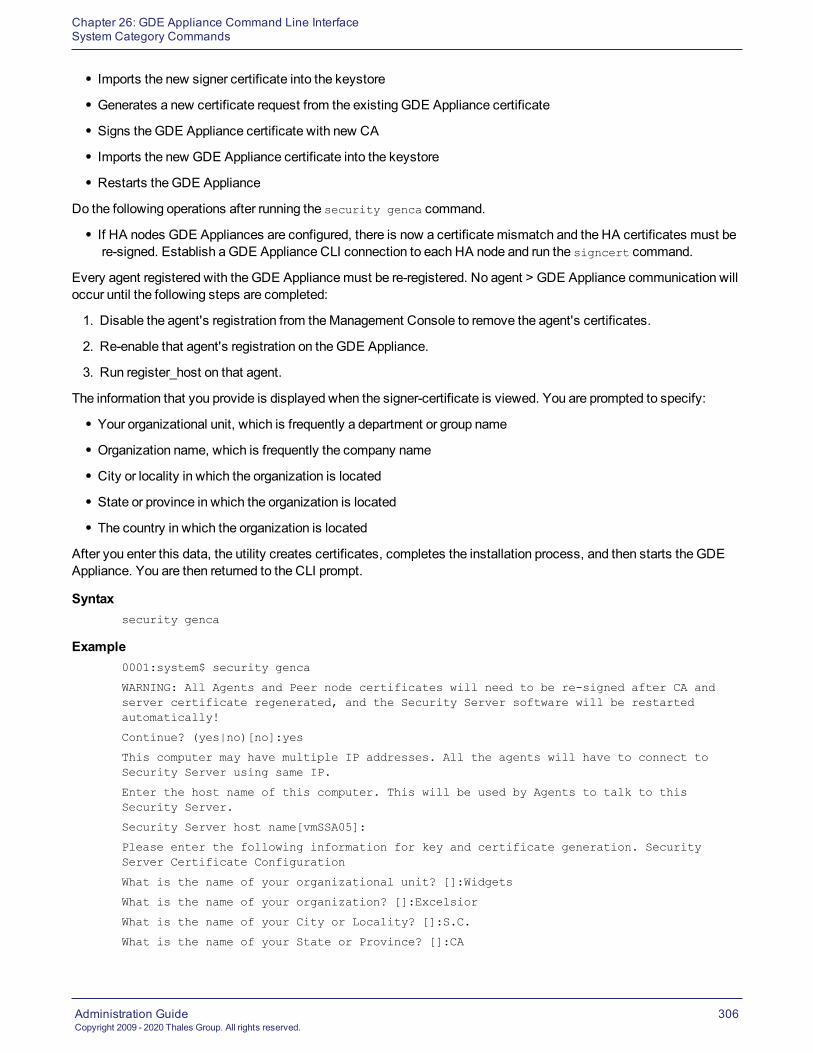
Chapter 26: GDE Appliance Command Line InterfaceSystem Category Commands
Administration GuideCopyright 2009 - 2020 Thales Group. All rights reserved.
306
l Imports the new signer certificate into the keystore
l Generates a new certificate request from the existing GDE Appliance certificate
l Signs the GDE Appliance certificate with new CA
l Imports the new GDE Appliance certificate into the keystore
l Restarts the GDE Appliance
Do the following operations after running the security genca command.
l If HA nodes GDE Appliances are configured, there is now a certificate mismatch and the HA certificates must bere-signed. Establish a GDE Appliance CLI connection to each HA node and run the signcert command.
Every agent registered with the GDE Appliancemust be re-registered. No agent > GDE Appliance communication willoccur until the following steps are completed:
1. Disable the agent's registration from theManagement Console to remove the agent's certificates.
2. Re-enable that agent's registration on theGDE Appliance.
3. Run register_host on that agent.
The information that you provide is displayed when the signer-certificate is viewed. You are prompted to specify:
l Your organizational unit, which is frequently a department or group name
l Organization name, which is frequently the company name
l City or locality in which the organization is located
l State or province in which the organization is located
l The country in which the organization is located
After you enter this data, the utility creates certificates, completes the installation process, and then starts the GDEAppliance. You are then returned to the CLI prompt.
Syntaxsecurity genca
Example0001:system$ security genca
WARNING: All Agents and Peer node certificates will need to be re-signed after CA andserver certificate regenerated, and the Security Server software will be restartedautomatically!
Continue? (yes|no)[no]:yes
This computer may have multiple IP addresses. All the agents will have to connect toSecurity Server using same IP.
Enter the host name of this computer. This will be used by Agents to talk to thisSecurity Server.
Security Server host name[vmSSA05]:
Please enter the following information for key and certificate generation. SecurityServer Certificate Configuration
What is the name of your organizational unit? []:Widgets
What is the name of your organization? []:Excelsior
What is the name of your City or Locality? []:S.C.
What is the name of your State or Province? []:CA

Chapter 26: GDE Appliance Command Line InterfaceSystem Category Commands
Administration GuideCopyright 2009 - 2020 Thales Group. All rights reserved.
307
What is your two-letter country code? [US]:
What is your email address? []:
What is the validity period of the generated certificate (from 2 to 10 years)? [10]:
Regenerating the CA and server certificates now...
SUCCESS: The CA and security certificates are re-generated and the Security Serversoftware is restarted.
0002:system$
suitebThe suiteb command has been deprecated. Usemode instead.
modeThe mode command is used to activate or deactivate suiteb , compatible, or RSA mode.
Syntaxsecurity mode [set [suiteb | compatible | rsa]] | [show]
The mode command can take the following arguments:
set This command activates or deactivates suiteb, compatible, or RSA mode[suiteb | compatible | rsa]
show Show security mode configuration
Table 26-20: Security mode command arguments
TheGDE Appliance is in compatible mode by default. The suiteb or RSA modes must be enabled to take effect.
Compatibility mode uses both RSA and ECC certificates. TheGDE Appliance uses the ECC certificate tocommunicate with other GDE Appliances, newly installed or upgraded agents. It uses the RSA certificate tocommunicate with older agents. When the agent negotiates a transaction with the GDE Appliance, the handshakedetermines which certificate to use.
Suiteb uses only ECC certificates. Older agents that do not support ECC must be upgraded or they will fail tocommunicate with the GDE Appliance.
RSA mode uses only RSA certificates. Any agents that registered when RSA modewas enabledmust re-registerbecause the ECC port is now closed. In order to communicate with the GDE Appliance, agents must re-register withthat GDE Appliance.
Examples
The following example activates suitebmode:0008:system$ security mode set suiteb
System Response:Important!: Ensure DSM ports 8446-8448 are not blocked by corporate firewall.
In addition, all other DSMs in this cluster must be manually set to the suiteb mode.
The Security Server will be restarted.
Continue? (yes|no)[no]:
The following example shows whether suiteb is configured:0003:system$ security mode show

Chapter 26: GDE Appliance Command Line InterfaceSystem Category Commands
Administration GuideCopyright 2009 - 2020 Thales Group. All rights reserved.
308
Current mode is: suiteb
SUCCESS: showed security mode status
The following example activates RSA mode:0004:system$ security mode set rsa
Important!: Ensure DSM ports 8443-8445 are not blocked by corporate firewall.
In addition, all other DSMs in this cluster must also be in rsa mode.
The Security Server will be restarted.
Continue? (yes|no)[no]:
Type yes to enable RSA mode.
ccThe cc command is used to enable or disable CommonCriteria mode.
Syntaxsecurity cc [on | off | show]
The cc command takes the following arguments:
on Enable Common Criteria mode
off Disable Common Criteria mode
show Show console port status
Table 26-21: Security cc command arguments
Example
The following example enables CommonCriteria mode:0001:system$ security cc on
cc (Common Criteria) mode is node specific configuration, and need to be configured ineach cluster node individually. Turning on cc (Common Criteria) will improve thesecurity level but limit some functionality, and server will restart automatically,continue? (yes|no)[no]:
The following example shows whether CommonCriteria is enabled:0002:system$ security cc show
SUCCESS: Common Criteria mode is off
0003:system$
boot-passphraseThe boot-passphrase command sets andmanages a passphrase required at GDE Appliance system boot time tounlock the system. Refer to the Installation & Configuration Guide for more information about this feature.
Syntaxsecurity boot-passphrase [ set | clear | show ]
security boot-passphrase recovery [ show [<filename>] | delete <filename> ]

Chapter 26: GDE Appliance Command Line InterfaceSystem Category Commands
Administration GuideCopyright 2009 - 2020 Thales Group. All rights reserved.
309
set Set a boot-passphrase to unlock the GDE Appliance filesystem at system boot up
clear Clears the boot passphrase
show Shows whether a boot-passphrase has been set or not
recovery show Displays the passphrase recovery file and displays the contents—the encryptedpassphrase, the public key used to encrypt the passphrase, and a sample command torecover the passphrase using the associated private key
recovery delete Deletes the passphrase recovery file
Table 26-22: Security boot-passphrase command arguments
Example 1
The following example shows how to set a boot passphrase. After setting the passphrase, the GDE Appliance rebootsand the SSH console connection is lost. You need to have IPMI Java console access, or if using a virtual appliance,you can connect to the GDE Appliance via the console available from the virtualization application in use. Refer to theInstallation & Configuration Guide for details about setting a boot passphrase.
0000:dsm$ system
0001:system$ security boot-passphrase set
An RSA public key with minimum length of 2048 bits is required for boot passphraserecovery. Please enter one now, ending with an empty line:
-----BEGIN PUBLIC KEY-----
MIIBIjANBgkqhkiG9w0BAQEFAAOCAQ8AMIIBCgKCAQEAwYIf0Z04nzne9j78BY7m
Q9kMTgh8YErtklECnVVhxExob/UvAWOvSBcGDVgixpeMCywWVh8OgTIbj751PVfa
TI8/C+gP4Rd6cdtO7fGzsYsAZxN9OCssRQlCJfCe6y6fNep3dDOh1noTFyFNTqOy
c3WW0gAlJ9ILPwn6uxVRgtXPgLnFfP9zNieyWmHTLw6He8BZAAYkWbESMgnA5BoJ
mcxdpv/i/8ZODTMMo/6Ji4oYpQPa8i9Ex7qTZinl5hxjIjC8eIcUOMNdAhvslNzs
T6FZPJ2BEYBU6TAQpxDPLwPAQIEw1x/NzcYUUfgaP1pZIAdhWFJUZkx4FqmEA5od
MwIDAQAB
-----END PUBLIC KEY-----
Enter new boot passphrase:
Enter new boot passphrase again:
WARNING: After setting the new boot passphrase, the system will be rebootedautomatically and the new passphrase must be entered on the console. If you do not havedirect or IPMI access to the console, then choose 'no' to cancel. DSM will not boot upuntil a correct boot passphrase is entered.
Continue? (yes|no)[no]: yes
NOTE: run this command on every server node in the cluster to keep them at a uniformsecurity level.
SUCCESS: custom boot passphrase has been set.
DSM server is rebooting...
Example 2
The following example shows whether a boot passphrase has been set or not:0008:system$ security boot-passphrase show
Prompt-On-Boot mode - the system disk is encrypted and there is a custom boot passphraseset.
SUCCESS

Chapter 26: GDE Appliance Command Line InterfaceSystem Category Commands
Administration GuideCopyright 2009 - 2020 Thales Group. All rights reserved.
310
0009:system$
Example 3
The following example shows the recovery file and the contents of that file0000:dsm$ system
0001:system$ security boot-passphrase recovery show
SUCCESS
The following passphrase recovery files are available:
0. 201710031407
Type the number of a file to view the contents, or 'q' to quit: 0
Encrypted passphrase (base64 encoded):
fqWOGbKe4x6R3vmWtBMFvoAauaEpOnQ9OGLmFW9eZhFbv+w1+u0LPgIGYx9e5ATH8GOvuJvht7UzBodMA07DHNMpyMnOEsy6Nz+ouWsMWhHen5JFNMXKWM9TYQ9/yrW/2McKIYuBqgeaOefzL2jr8vyyFudq6TGgTjRJe1edLDCqTJbcK100o036U0vynLpes6Zp1ud5usWngn2J2X6PrlAugHp4nMMDIRLQBgzX95x7Fb7VLebcb/eIGn39xh/f6azXhHpjahwjirzfpZl0300VFYT0P9o5xg==
Public key used for encryption:
-----BEGIN PUBLIC KEY-----MIIBIjANBgkqhkiG9w0BAQEFAAOCAQ8AMIIBCgKCAQEAwYIf0Z04nzne9j78BY7Q9kMTgh8YErtklECnVVhxExob/UvAWOvSBcGDVgixpeMCywWVh8OgTIbj751PVfTI8/C+gP4Rd6cdtO7fGzsYsAZxN9OCssRQlCJfCe6y6fNep3dDOh1noTFyFNTqOc3WW0gAlJ9ILPwn6uxVRgtXPgLnFfP9zNieyWmHTLw6He8BZAAYkWbESMgnA5Bomcxdpv/i/8ZODTMMo/6Ji4oYpQPa8i9Ex7qTZinl5hxjIjC8eIcUOMNdAhvslNzT6FZPJ2BEYBU6TAQpxDPLwPAQIEw1x/NzcYUUfgaP1pZIAdhWFJUZkx4FqmEA5oMwIDAQAB
-----END PUBLIC KEY-----
Example command for decrypting the passphrase, given the matching private key:
base64 -d <file-containing-the-ciphertext-above> | openssl rsautl -inkey <private-key> -decrypt
SUCCESS
Example 4
The following example clears the boot passphrase. When you clear the passphrase the recovery file is not deleted,you can delete it later, see next example:
0004:system$ security boot-passphrase clear
Enter current boot passphrase:
WARNING: After clearing the custom boot passphrase, the system will be rebootedautomatically!
Continue? (yes|no)[no]: ^C
0005:system$ security boot-passphrase clear
Enter current boot passphrase:
WARNING: After clearing the custom boot passphrase, the system will be rebootedautomatically!
Continue? (yes|no)[no]: yes
NOTE: run this command on every server node in the cluster to keep them at a uniformsecurity level.
This operation will take some time, please wait....
SUCCESS: custom boot passphrase has been cleared, unattended boot enabled.

Chapter 26: GDE Appliance Command Line InterfaceSystem Category Commands
Administration GuideCopyright 2009 - 2020 Thales Group. All rights reserved.
311
DSM server is rebooting
0006:system$
Example 5
The following example deletes the passphrase recovery file:0003:system$ security boot-passphrase recovery delete 201710031407
SUCCESS: removed passphrase recovery file '201710031407'
0004:system$
legacyregistrationPort 8080 is no longer used for registration, but you canmanually close/open this legacy port for new deployment.
Syntax# security legacyregistration [ on | off | show ]
Example# security legacyregistration show
mfauthThe mfauth command enables or disables themulti-factor authentication of GDE ApplianceManagement Consoleadministrators. When enabled, theManagement Console login screen displays the usual Login andPassword boxes.
l GDE ApplianceManagement Console administrators with multi-factor authenticationmust enter the valuedisplayed on their RSA SecurID device into thePassword box.
l GDE ApplianceManagement Console administrators without multi-factor authentication should enter the GDEAppliance administrator password in the Password box.
The mfauth command includes a clean option to remove all configured administrator:device bindings. To remove theadministrator:device bindings of individual Management Console administrators, open the Edit Administrator windowand delete the value in theRSA User Name box.
The mfauth command displays the enabled/disabled status of multi-factor authentication. The current mfauth statusis also indicated in theSystem > General Preferences > System tab. TheMulti-Factor Authentication Statuscheckbox is a display indicator only and cannot be set in theManagement Console.
Do not enablemulti-factor authentication until after the RSA Authentication Agent is configured on theGDE Appliance.
NoteYoumust enable mfauth on all HA nodes. If not, it results in an HA node databasemismatch.
Syntaxmfauth on | off | clean | show
Example
The following example shows the current multi-factor configuration status of the GDE Appliance. TheGDE Applianceis configured for multi-factor authentication. It’s just not enabled.
0001:system$ mfauth show
Administrator multiple factor authentication : off
RSA secret file configured : on
SUCCESS: administrator multiple factor authentication status showed.

Chapter 26: GDE Appliance Command Line InterfaceSystem Category Commands
Administration GuideCopyright 2009 - 2020 Thales Group. All rights reserved.
312
0002:system$
The following example enables multi-factor authentication for GDE Appliance administrators.0010:system$ mfauth on
WARNING: After enabling the administrator multiple factor authentication, the securityserver software will start to validate the extra one-time password!
Continue? (yes|no)[no]:yes
SUCCESS: administrator multiple factor authentication enabled.
0011:system$
The following example deletes the RSA node secret file from theGDE Appliance, effectively breaking allcommunication between theGDE Appliance and the RSA AuthenticationManager, which, in turn, disables multi-factor authentication of GDE Appliance administrators. If you remove the node secret using mfauth clean, youmustalso delete the node secret on the RSA Security Console by running Clear Node Secret. A new node secret will beautomatically generated the next time any Vormetric administrator logs into theManagement Console. To break allGDE Appliance administrator device bindings on theGDE Appliance:
0001:system$ mfauth clean
WARNING: Cleaning RSA secret file will break the communication between the securityserver and RSA server!
Continue? (yes|no)[no]:yes
SUCCESS: RSA secret file is removed.
0002:system$
tls1The tls1 command enables or disables support for TLS protocols v1.0 and 1.1. This command turns on or turns offsupport for both v1.0 and v1.1 of the TLS protocol, you cannot select one or the other.
Syntaxtls1 [on | off | show]
The tls1 command takes the following arguments:
on Enable TLS 1.0/1.1 support
off Disable TLS v1.0/1.1 support
show Show status of TLS v1.0/1.1 support (enabled or not)
Table 26-23: System tls1 command arguments
Example
The following example turns on TLS v1.0/1.1:0002:system$ tls1 on
WARNING: After enabling TLS 1.0/1.1, the security server software will restart!
Continue? (yes|no)[no]:yes
SUCCESS: TLS 1.0/1.1 enabled and server restarted.
This change only affected this node. Run the same tls1 command on all other nodes in thecluster.
0003:system$
The following example shows whether TLS v1.0/1.1 is enabled or not:0004:system$ tls1 show

Chapter 26: GDE Appliance Command Line InterfaceSystem Category Commands
Administration GuideCopyright 2009 - 2020 Thales Group. All rights reserved.
313
TLS 1.0/1.1 is disabled
SUCCESS: TLS 1.0/1.1 status shown
0005:system$
shutdownThe shutdown command stops the GDE Appliance software, brings down the appliance operating system, and thenpowers off the appliance. Configuration changes are automatically saved. Afterwards, the appliance can be safelyturned off.
Syntaxshutdown
Example
The following example shuts the system down:0038:system$ shutdown
Do you want to shutdown the system ? (y/n):y
Shutting down now...
Shutdown SUCCESS
0039:system$
The last message displayed on the appliance LCD before it powers down is:Power off or reboot in approx 15 secs
You can remove the power cords and powermodules after the appliance powers down. Reapply power by reattachingthe power cords and pressing the power switch. The power-interrupt alarm may sound. If it does, press the red resetbutton on the back of the appliance.
rebootThe reboot command reboots the GDE Appliance appliance.
Syntaxreboot
Example
The following example reboots the system immediately:0001:system$ reboot
Reboot the system y/n?
Rebooting now...
Reboot SUCCESS
system$
Broadcast message from root (Sun Feb 9 02:44:20 2014):
The system is going down for reboot NOW!
serverPrevious CLI commands limited the GDE Appliance CLI administrator to do a restart of the GDE Appliance. Thecommands have been enhanced so that GDE Appliance CLI administrators can start and stop the GDE Appliancebased on the need for maintenance intervals, test cycles and so on. Available server commands are listed below:

Chapter 26: GDE Appliance Command Line InterfaceMaintenance Category Commands
Administration GuideCopyright 2009 - 2020 Thales Group. All rights reserved.
314
restart Restarts the GDE Appliance software. Shuts down the GDE Appliance software and then restartsit.
start Starts the GDE Appliance software.
stop Stops the GDE Appliance software.
status Displays the GDE Appliance software running status.
Table 26-24: System category server commands
restartThe restart command stops and then starts the GDE Appliance software. It does not reboot the appliance. Thereboot command restarts the GDE Appliance operating system and, in the process of coming up, starts the GDEAppliance software. Use the reboot command only if restart does not correct a problem.
Syntaxrestart
Example
The following example restarts the GDE Appliance:0033:system$ server restartDo you want to restart the server software ? (y/n):y
Restarting now...
Stopping Security Server...done.
Stopping the data store...done.
Starting Security Server...done.
SUCCESS: The security server software is restarted.
0034:system$
statusThe status command displays the current running status of the GDE Appliance software.
Syntaxstatus
Example
The following example shows the status display.0038:system$ server status
Security Server is running.
Security Server uptime: 2 days, 09:27:27
SUCCESS: The security server software status is shown.
Maintenance Category CommandsThemaintenance category is used to restore the GDE Appliance to factory defaults, upgrade the current GDEAppliance installation, and set operating system attributes, such as date, time, and time zone.
Enter themaintenance category by typing:0009:dsm$ maintenance

Chapter 26: GDE Appliance Command Line InterfaceMaintenance Category Commands
Administration GuideCopyright 2009 - 2020 Thales Group. All rights reserved.
315
0010:maintenance$
Themaintenance category consists of the following commands:
config This command restores the appliance image and configuration to the same state and versionat which the appliance was shipped from the factory.This command also configures automatic backup and remote archival.
showver Displays the GDE Appliance versions that are on the system and indicates the version that iscurrently running.
delver Deletes a GDE Appliance image from the GDE Appliance.
ntpdate Configures one or more Network Time Protocol (NTP) servers with which to synchronize thesystem clock.
date Sets the system date.
time Sets the system time.
gmttimezone Sets the system time zone.
diag Displays GDE Appliance and system logs, available system disk space, system OS version,and system uptime.
repair System configuration recovery
Table 26-25: CLI maintenance category commands
configThis section describes using the CLI maintenance category config command to delete the GDE Applianceconfiguration or restore the GDE Appliance to its original factory configuration.
The config reset and config load default commands restore the GDE Appliance installation to an unconfiguredstate.
The config reset command removes all the configuration data that was added after the current GDE Appliancesoftware was installed. The command preserves the currently installed GDE Appliance software, but removes allconfiguration data except the network configuration .
NoteThe config load default command causes a reboot of the GDE Appliance. When the command is issued,wait for the system to fully reboot and restart. Do not cycle power. Critical system files are installed on thereboot following a config load default so it is important to wait until it has completed
The config load default command is an extreme form of config reset. The config load default commanddeletes everything from the appliance and restores the sameGDE Appliance installation with which the appliance wasshipped. The partitions that contain GDE Appliance installations are deleted from the appliance, so there is no hope ofretrieving any data once this command is executed.
The config load default command produces the same result as the Kill switch:
l Execute this CLI commandwhen there is a serial console connection to the appliance, or when there is a terminalwindow from which to SSH onto the appliance.
l Press the Kill Switch when you do not have console or terminal access, but you do have access to the physicalappliance.

Chapter 26: GDE Appliance Command Line InterfaceMaintenance Category Commands
Administration GuideCopyright 2009 - 2020 Thales Group. All rights reserved.
316
The config reset and config load default commands discard the CA signer certificate. The CA signercertificates must be restored from a backup or regenerated later.
Syntax
The following is the CLI config command syntax:config load default
config reset
The config command supports the following arguments:
load Removes the current GDE Appliance installation and restores the manufacturer default GDEAppliance installation. It removes all policies, hosts, keys, and so on from the GDE Appliance.
reset Preserves the currently installed GDE Appliance software but removes all configuration data,except the network configuration.
Table 26-26: Maintenance category config commands
The following example deletes the partitions that contain GDE Appliance installations. Everything that has been addedsince the appliance was first started is deleted. The appliance reboots and loads the original GDE Applianceinstallation.
NoteThe original GDE Appliance installation will not contain any patches or upgrades.
Example 10011:maintenance$ config load default
Loading manufacture default will wipe out all the configuration data and set the machineconfiguration to the manufacture default. System will reboot automatically.
Continue? (yes|no)[no]:yes
config load SUCCESS.
0012:maintenance$
Example 2
The following example resets the current GDE Appliance installation back to its initial unconfigured state. Thiscommand returns database and configuration files to their original, fresh installation state without changing orreinstalling the current GDE Appliance version.
0003:maintenance$ config reset
Reset configuration will wipe out all the configuration data and set the configurationdata to the manufacture default. System will reboot automatically.
Continue? (yes|no)[no]:yes
config reset SUCCESS. You can reboot the Security Server now or it will rebootautomatically in 60 seconds.
Retrieving Security WorldWhat is the validity period of the generated certificate (from 2 to 10 years)? [10]:
showverThe showver command displays the GDE Appliance software images that have been uploaded and that are availablefor use. TheGDE Appliance comes from the factory with one image pre-installed. Up to two images can be installedand configured at one time. Software patches are not displayed by this or any other command.

Chapter 26: GDE Appliance Command Line InterfaceMaintenance Category Commands
Administration GuideCopyright 2009 - 2020 Thales Group. All rights reserved.
317
Syntaxshowver
Example
Enter the showver commandwithout any arguments to display the current image. For example:0001:maintenance$ showverver_count=1cur_ver=6.0
show version SUCCESS
0002:maintenance$
delverThe delver command deletes the inactive GDE Appliance image from the system. Up to two images can be installedon the appliance or system at one time. As image updates become available, you will cycle through the installedimages, usually deleting the older of the two images. You cannot delete an active image, nor can you simply stop theGDE Appliance.
Syntaxdelver
You are prompted to continue.
Example
The following example deletes the image from the system.0010:maintenance$ delver
You are deleting the alternative software version.Continue? (yes|no)[no]:yes
Delete version SUCCESS
0011:maintenance$
ntpdateThe ntpdate command:
l Configures one to four Network Time Protocol (NTP) servers for the current GDE Appliance
l Enables and disables NTP on the appliance
l Forces immediate clock synchronization with an NTP server
l Shows the current NTP configuration status
When NTP is configured and enabled, at one hour intervals the CLI daemon synchronizes the system clock of theGDE Appliance with the first available NTP server. If, within one second, the GDE Appliance cannot connect with theNTP server, the CLI daemon tries the next NTP server in the list. The NTP server can reside in any time zone.
Syntaxntpdate sync | add SERVER_ADDRESS | delete SERVER_ADDRESS | on | off | show
The ntpdate command takes the following arguments:
sync forces clock synchronization with the first available NTP server.
Table 26-27: ntpdate command arguments

Chapter 26: GDE Appliance Command Line InterfaceMaintenance Category Commands
Administration GuideCopyright 2009 - 2020 Thales Group. All rights reserved.
318
add SERVER_ADDRESS adds the named NTP server to the list of servers to contact for time synchronization. At leastone server must be configured before you can enable (turn on) time synchronization. You mayconfigure up to four NTP servers.
delete SERVER_ADDRESS removes the named NTP server from the list of servers to contact for time synchronization.Time synchronization is disabled (turned off) when the last NTP server is removed from thelist.
on enables NTP time synchronization. At least one NTP server must be configured before youcan enable synchronization.
off disables time synchronization and leaves the current NTP server list intact. You can re-enablesynchronization without having to reconfigure the NTP servers.
show Displays the NTP server configuration and state. The ntpdate show command does not sort theoutput. It displays all the configured NTP servers in the same order that they were added to theGDE Appliance.
Table 26-27: ntpdate command arguments (continued)
sync, add, delete, on, off, and show are literals that are entered as shown or in abbreviated form.
Examples
The following examples:
l displays the default NTP configuration environment
l adds four NTP servers
l enables NTP synchronization
l displays a fully-configured NTP environment
l synchronizes the appliance clock with the first available NTP server clock
l swaps the last two NTP servers in the list to change access order0001:maintenance$ ntpdate showTotal ntpdate server number : 0ntpdate is off
ntpdate SUCCESS
0007:maintenance$ ntpdate add 172.16.78.110
ntpdate SUCCESS
0008:maintenance$ ntpdate add search.domain.com
ntpdate SUCCESS
0009:maintenance$ ntpdate add 172.30.45.115
ntpdate SUCCESS
0010:maintenance$ ntpdate add 172.20.244.75
ntpdate SUCCESS
0011:maintenance$ ntpdate on
ntpdate SUCCESS
0012:maintenance$ ntpdate show
Total ntpdate server number : 4
ntpdate server [1] : 172.16.78.100
ntpdate server [2] : search.domain.com
ntpdate server [3] : 172.30.45.115

Chapter 26: GDE Appliance Command Line InterfaceMaintenance Category Commands
Administration GuideCopyright 2009 - 2020 Thales Group. All rights reserved.
319
ntpdate server [4] : 172.20.244.75
ntpdate is on
ntpdate SUCCESS
0013:maintenance$ ntpdate sync
ntpdate SUCCESS
0014:maintenance$ ntpdate delete 172.16.78.100
ntpdate SUCCESS
0015:maintenance$ ntpdate add 172.16.78.100
ntpdate SUCCESS
0016:maintenance$ ntpdate show
Total ntpdate server number : 4
ntpdate server [1] : 172.30.78.100
ntpdate server [2] : search.domain.com
ntpdate server [3] : 172.20.244.75
ntpdate server [4] : 172.16.78.100
ntpdate is on
ntpdate SUCCESS
0017:maintenance$
dateThe date command in the maintenance category is used to set or to display the date on the system. The datecommandwithout any arguments displays the current system date. If a parameter is included with the date commandit resets the system date to the specified date.
Syntax
The syntax for the date command is:date MM/DD/YYYY
date
Example
To set the date on the system to December 20th, 2014, enter the following:0001:maintenance$ date 12/20/2014
The following example displays the system date:0004:maintenance$ date
month=Dec day=20 year=2014
Show system date SUCCESS
0005:maintenance$
timeThe time command sets or to displays the time on the system using a 24-hour clock. When no parametersaccompany the time command, it displays the current system time. If a parameter is included with the time command,it resets the system time to the specified value.
Syntax
The syntax for the time command is:

Chapter 26: GDE Appliance Command Line InterfaceMaintenance Category Commands
Administration GuideCopyright 2009 - 2020 Thales Group. All rights reserved.
320
time HH:MM:SS
time
Example
To set the time on the system enter the following:0001:maintenance$ time 02:23:00
This sets the system to 2:23 AM.
The following example uses the time command to display the system time:0003:maintenance$ time
hour=18 min=22 sec=38 zone=PDT
Show system time SUCCESS
gmttimezoneThe gmttimezone command in themaintenance category is used to set the system time zone. If a parameter isincluded with the gmttimezone command, it sets the time to the zone specified. To see a list of supported time zones,enter gmttimezone list.
Syntax
The syntax for the gmttimezone command is:gmttimezone {list|show|set zonename}
gmttimezone list
gmttimezone show
Example
To list and set the gmttimezone on the system enter the following:0025:maintenance$ gmttimezone list
...
(GMT-07:00) America/Phoenix (Mountain Standard Time)
(GMT-07:00) America/Shiprock (Mountain Standard Time)
(GMT-07:00) America/Yellowknife (Mountain Standard Time)
(GMT-08:00) America/Dawson (Pacific Standard Time)
(GMT-08:00) America/Los_Angeles (Pacific Standard Time)
(GMT-08:00) America/Tijuana (Pacific Standard Time)
(GMT-08:00) America/Vancouver (Pacific Standard Time)
(GMT-08:00) America/Whitehorse (Pacific Standard Time)
(GMT-08:00) Pacific/Pitcairn
(GMT-09:00) America/Anchorage
...
0026:maintenance$ gmttimezone show
Timezone is set to : US/Pacific
Show timezone SUCCESS
0030:maintenance$ gmttimezone set America/Tijuana
Set timezone SUCCESS
0031:maintenance$ gmttimezone show
Timezone is set to : America/Tijuana

Chapter 26: GDE Appliance Command Line InterfaceMaintenance Category Commands
Administration GuideCopyright 2009 - 2020 Thales Group. All rights reserved.
321
Show timezone SUCCESS
diagThe diag command in the maintenance category displays OS system information and related log files. This commandis available in appliance-based installations only.
diskusage Displays system disk space usage.
hardware View RAID and motherboard status.
log Lists and displays system messages and logs.
osversion Displays the system kernel version.
tlsmon Monitor TLS connections and generate audit logs.
uptime Displays how long the system has been running since the last reboot, the current number ofadministrators logged into the system, and CPU load usage.
vmstat Displays CPU and memory usage.
Table 26-28: Maintenance category diag command arguments
diskusageThe diskusage argument to the diag command displays information about the system disk, such as partitions,amount of used and available disk space, percentage of free space, and partition names.
Syntaxdiag diskusage
Example0017:maintenance$ diag diskusage
Filesystem 1M-blocks Used Available Use% Mounted on
/dev/sda6 9389 4403 4510 50% /
/dev/sda9 254458 939 240594 1% /partitions/large
/dev/sda1 935 22 866 3% /grub
tmpfs 1963 0 1963 0% /dev/shm
/dev/sda2 7511 2307 4823 33% /partitions/std/2
/dev/sda8 7513 155 6977 3% /tmp
SUCCESS: Show disk usage
0018:maintenance$
logThe log argument to the diag command is used to list and view system files on the GDE Appliance.
Syntaxdiag log list
diag log view <file>
The diag log command supports three additional arguments, list and view.

Chapter 26: GDE Appliance Command Line InterfaceMaintenance Category Commands
Administration GuideCopyright 2009 - 2020 Thales Group. All rights reserved.
322
The list argument displays the system files that are available for viewing. It takes no additional input. The viewargument takes the name of the log file to display. The view argument calls the "more" system command to display thefile. Some of the "more" command display options are supported.
Active logs are log files that being currently written to and updated by GDE Appliance processes. Inactive logs arelogs that have been filled to capacity and then closed. The name of the closed log file is the original name usuallyappended with the date. For example, the name of the active GDE Appliance log is cgss.log. When it reaches theconfigured capacity, it is made inactive and renamed to cgss.log.YYYY-MM-DD.
TheGDE Appliance log files that you can view are described below:
l The server.log file contains details about agent backup and restore requests, connection status, ManagementConsole interaction, Java exceptions, JBoss start and stop processes, andmore. This file contains diverseinformation and it should be the first file you check for problems that are related to GDE Appliance operation.
l The cgss.log file contains a record of the events that make up the BEK generation process for an agentrequesting tomake a backup, as well as the names of uploaded audit files. This file does not contain events thatpertain to restore operations. Check this file if the agent fails to back up a database, even though agent/GDEAppliance authentication is correctly configured, and the policy for this agent permits the backup operation.
l The messages file is generated by syslog. It contains kernel entries for enabling/disabling the log service, memoryusage, CPU usage, system calls, device initialization, and so on. It also contains log entries that wouldotherwise be displayed in theMessage Log but, for some reason, cannot be uploaded to the GDE Appliance. Themessages file follows the standard naming convention to cycle large files. For example, the active file ismessages. The cycled files are messages.1, messages.2, messages.3, and so on.
Example 1
To list the files that are available for viewing:0011:maintenance$ diag log list
messages
messages.1
messages.2
messages.3
messages.4
cgss.log
cgss.log.2014-01-08
server.log
server.log.2014-01-15
SUCCESS: list log file
0012:maintenance$
Example 2
To display a log file, execute the diag log view command followed by the name of the file to view. For example:0018:maintenance$ diag log view cgss.log
...
2014-01-19 19:09:22,025 INFO [com.vormetric.server.sdk.user.UserManager] EnteringcreateUser
2014-01-19 19:09:22,025 INFO [com.vormetric.server.sdk.user.UserManager] User isauthorized. Generating password...
2014-01-19 19:09:22,025 INFO [com.vormetric.server.sdk.user.UserManager] Verifyingwhether the password meets the PasswordPolicy conditions...

Chapter 26: GDE Appliance Command Line InterfaceMaintenance Category Commands
Administration GuideCopyright 2009 - 2020 Thales Group. All rights reserved.
323
2014-01-19 19:09:22,027 INFO [com.vormetric.server.sdk.user.UserManager] Verifyingcomplete: Password meets all the PasswordPolicy conditions
2014-01-19 19:09:22,032 INFO [com.vormetric.server.sdk.user.UserManager] Passwordgeneration complete
...
0019:maintenance$
osversionThe osversion command displays the operating system version and kernel that is running on theGDE Appliance. Theosversion command is equivalent to the Linux "uname -a" command.
Syntaxosversion
Example
To display the appliance operating system version and kernel:0014:maintenance$ diag osversion
Linux SSA666 2.6.18-128.el5PAE #1 SMP Wed Jan 21 11:19:46 EST 2009 i686 i686 i386GNU/Linux
SUCCESS: Show version
uptimeThe uptime command displays the amount of time the operating system has been running since the last bootup. Italso displays the system load and the number of GDE Appliance CLI administrators that are currently running CLIsessions on theGDE Appliance. Administrators that are configured in the GDE ApplianceManagement Console GUIare not included in the count becauseGDE Appliance CLI administrators are actual system users andManagementConsole administrators exist only in the GDE Appliance database. The uptime command is equivalent to the Linux"uptime" command.
Syntaxuptime
Example
To display the amount of time that the appliance has been running, system load, and the number of current GDEAppliance CLI sessions:
0019:maintenance$ diag uptime
17:02:20 up 3 days, 22:02, 2 users, load average: 0.14, 0.06, 0.01
SUCCESS: Show uptime
0020:maintenance$
vmstatThe vmstat argument to the diag command displays information about the system disk, such as partitions, amount ofused and available disk space, percentage of free space, and partition names.
Syntaxdiag vmstat
Example0001:maintenance$ diag vmstat

Chapter 26: GDE Appliance Command Line InterfaceMaintenance Category Commands
Administration GuideCopyright 2009 - 2020 Thales Group. All rights reserved.
324
procs -----memory- --swap---io---system-----cpu-----
r b swpd free buff cache si so bi bo in cs us sy id wa st
1 0 0 4984848 203208 3793404 0 0 0 12 10 2 0 0 99 00
SUCCESS: Show vmstat result
0002:maintenance$
repair
vacuumThe vacuum feature compacts and defragments the postgres database.
Syntaxrepair [vacuum | prunewal| purgepolicyhistory ]
Example0003:maintenance$ repair vacuum
running vacuum will temporarily lock all tables.
Continue? (yes|no)[no]: yes
SUCCESS: vacuum db done
NoteRunning the repair vacuum function is disruptive. Thales recommends that you perform this functionwhen server traffic is light.
prunewalIf you have a large number of postgres transaction logs, they may potentially take up a large amount of storage spaceand impact performance. The prunewal command clears (or prunes) the processed transaction logs to improveperformance.
Syntaxrepair [vacuum | prunewal | purgepolicyhistory ]
Example0002:maintenance$ repair prunewal
running prunewal...
Continue? (yes|no)[no]: yes
SUCCESS: prunewal done
purge policy historyEach time any modification to a policy results in a new policy version, the old version is saved. These older versionsmay potentially take up a large amount of storage space and impact performance. Purging the policy history deletesthe old policy versions, thereby freeing up storage space and improving performance.
Syntaxrepair [vacuum | prunewal | purgepolicyhistory ]
Example0013:maintenance$ repair purgepolicyhistory

Chapter 26: GDE Appliance Command Line InterfaceHigh Availability Category Commands
Administration GuideCopyright 2009 - 2020 Thales Group. All rights reserved.
325
purge policy history will delete all of the archived history policy data andmodification logs.
Continue? (yes|no)[no]: yes
SUCCESS: purged all the policy history logs and data
High Availability Category CommandsHigh Availability (HA) is the configuration of multiple GDE Appliances in an HA cluster. EachGDE Appliance HA noderuns in parallel in an active-active format. When oneGDE Appliance HA node fails, the other DE Appliance HA nodesin the HA cluster continue to run. When the downedGDE Appliance HA node is up and running again, it synchronizeswith the other GDE Appliance HA nodes.
After configuring andmanaging any GDE Appliance HA node, it synchronizes with the other nodes within seconds sothat they remainmirror copies of each other.
HA configuration andmaintenance is done in both the GDE Appliance CLI and the UI Management Console.
add Add an HA node to the HA cluster, without configuring it for replication.
cleanup Cleanup HA configuration data on a local node, after it has been removed from anHA cluster.
join Join this node to an HA cluster and configure it for replication.
remove (reassign host) Remove a node from an HA cluster. If a host is assigned to the node, you mustreassign hosts to another node before removing the node from the cluster. Youcannot remove the node from the cluster while hosts are assigned to it.
show Lists all the GDE Appliance HA nodes in the HA cluster.
Table 26-29: HA category commands
addAdd a node to the HA cluster without configuring it for replication. Youmust add the node before it can join the cluster.You can add the node from either the UI or CLI of node 1 in the cluster.
Youmust add the new node to the HA cluster, from node 1.
Syntax
The syntax for the command is:add <haNodeName>
where, hostname is the host name or FQDN of an HA node.
Example
1. Log on to HA node 1.
2. Switch to the HA menu, type:0000:dsm$ ha
3. Add the HA node to the cluster, type:0003:ha$ add <haNodeName>
Example:0003:ha$ add HAnode2.i.vormetric.com

Chapter 26: GDE Appliance Command Line InterfaceHigh Availability Category Commands
Administration GuideCopyright 2009 - 2020 Thales Group. All rights reserved.
326
System Response:This command adds node 'HAnode2.i.vormetric.com' to the HA cluster (with'HAnode1.i.vormetric.com'), without configuring it for replication.
To configure it for replication, login to the CLI of '192.168.15.96' and execute the'join' command under 'ha'
Continue? (yes|no) [no]: yes
SUCCESS: Node added to HA cluster.
0004:ha$
cleanupThe cleanup command cleans up HA configuration data on the current HA node and restarts it.
NoteYoumust remove this node from the HA cluster before you can run this command. Perform a cleanupbefore you regenerate the node certificates and re-register the HA node with the HA cluster.
Syntaxcleanup
1. Log on to an HA node in the cluster, type:0002:ha$ cleanup
System Response:WARNING: This command cleans up HA configuration data of, and restarts, this server.
This may take several minutes.
Continue? (yes|no)[no]:
2. Type yes to continue.SUCCESS: cleanup
joinJoins the current node to the HA cluster. If you are joining an HA cluster after an upgrade, and the node previously hadhosts assigned to it, after it successfully joins the cluster, the GDE Appliance asks if you want the hosts restored tothe node.
longwait Longwait waits for approximately twice as long as the normal wait mode for the node replicationstatus state to be set to 'ready,' meaning that the node successfully joins the cluster.Note: Use if nodes are spread far apart geographically, or are in a cloud environment.Sometimes the Join function takes so long that the ssh session times out and terminatesautomatically before the Join can finish.
<enter> Joins the current GDE Appliance to the HA cluster.
Table 26-30: Join commands
Syntax
The syntax for the command is:join [ longwait | <enter>]
Example 2
0000:dsm$ join longwait | join <enter>

Chapter 26: GDE Appliance Command Line InterfaceHigh Availability Category Commands
Administration GuideCopyright 2009 - 2020 Thales Group. All rights reserved.
327
WARNING: This server node is about to join an HA cluster.
Please make sure the HA cluster is running and has this server node in its HA node list.
This may take several minutes.
Continue? (yes|no)[no]:yes
HA Initial Server host name:HAnode1.i.vormetric.com
Initial_Server=ss3-21-31 CAs_Fingerprint=BB:AD:33:55:89:76:1E:F9:6D:48:36:FE:BA:AB:EC:36:AA:A2:53:25
Initial Security Server system administrator name: tesadmin
Initial Security Server system administrator password:
This node may have multiple IP addresses. All of the agents will have to connect to the SecurityServer using the same IP.Enter the host name of this node. This will be used by Agents to talk to this Security Server.This Security Server host name[longhostnamenegativetest1oliversvm.qa.com]:Please enter the following information for key and certificate generation.What is the name of your organizational unit? []:What is the name of your organization? []:What is the name of your City or Locality? []:What is the name of your State or Province? []:What is your two-letter country code? [US]:What is your email address? []:What is the validity period of the generated certificate (from 2 to 10 years)? [10]:Initial Security Server host name:ss3-21-31Initial Security Server system administrator name:alladInitial Security Server system administrator password:xxxxxxxx
This Security Server host name[longhostnamenegativetest1oliversvm.qa.com]:longhostnamenegativetest1oliversvm.qa.comThe name of your organizational unit:The name of your organization:The name of your City or Locality:The name of your State or Province:Your two-letter country code[US]:USYour email address:
WARNING: all data on this DSM will be lost and will be sync'ed with the initial security serverin next step.Continue? (yes|no)[no]:yes
SUCCESS: joined the HA cluster
removeThe remove command removes an HA node from anHA cluster. Youmust issue the remove command for the nodefrom the initial node in the cluster. You cannot remove a node when you are logged into it.
If hosts are assigned to the node that you want to remove from the HA cluster, youmust reassign the hosts to anothernode before removing the node from the cluster. You cannot remove a node from the cluster while hosts are assignedto it.
You can choose tomove hosts to specific HA nodes by naming the host, or you can have theGDE Appliance evenlydistribute the hosts to balance the load in the HA cluster.
Tomove the hosts to a specific HA node, type:
0001:ha$ remove <HA_Node1> reassignhost <HA_node2>

Chapter 26: GDE Appliance Command Line InterfaceUser Category Commands
Administration GuideCopyright 2009 - 2020 Thales Group. All rights reserved.
328
Example
0001:ha$ remove dsm15099.i.vormetric.com reassignhost dsm15100.i.vormetric.com
To have theGDE Appliancemove the hosts to HA nodes and evenly distribute the load, type:
0001:ha$ remove <HA_Node1> reassignhost rr
Example
0001:ha$ remove dsm15099.i.vormetric.com reassignhost rr
System ResponseWARNING: This command removes the given server node from the HA cluster. After deletion,running the "ha cleanup" command from its CLI will be required.
This may take several minutes.
Continue? (yes|no)[no]:yes
Restore original host assignment back to this node (yes|no)[yes]:
1 hosts now assigned to <HA_Node1>
showThe show command displays all of the HA GDE Appliance nodes in the HA cluster. All of the HA nodes are listed,regardless if they are registered or not. You can execute the show command on any HA node in the cluster. The nodethat you are on is listed first in the list.
Syntaxshow
Example0001:ha$ show
System Response:List of Nodes in the Cluster:
HAnode1.i.vormetric.com
HAnode2.i.vormetric.com
HAnode3.i.vormetric.com
HAnode4.i.vormetric.com
User Category CommandsThe user category enables you to add, modify, delete, and display GDE Appliance CLI administrators. When settingup a new appliance, access the appliance or system through theGDE Appliance CLI and do basic applianceconfiguration, like IP address and host name. After the appliance or system is setup, you can run theManagementConsole to configure policies, keys, andGuardPoints.
CLI administrators are system users, and are not related to the administrators configured and displayed in theManagement Console. GDE Appliance CLI administrators configure the appliance network, configure HighAvailability, and do general appliance administrative tasks. A GDE Appliance CLI administrator cannot log into theManagement Console and aManagement Console administrator cannot log into the GDE Appliance CLI.
The user category supports the following commands:

Chapter 26: GDE Appliance Command Line InterfaceUser Category Commands
Administration GuideCopyright 2009 - 2020 Thales Group. All rights reserved.
329
add Adds a new CLI administrator.
delete Deletes a CLI administrator.
modify Changes a CLI administrator password.
show Lists all configured CLI administrators.
Table 26-31: CLI user category commands
addThe add command enables you to add new GDE Appliance CLI administrators.
CLI administrators are system administrators and are not related to the administrators configured and displayed in theManagement Console. Administrators created in theManagement Console are placed in the GDE Appliancedatabase, and follow the strong password requirements set theManagement Console Password window.Administrators created via the CLI are also placed in the /etc/passwd file on the system, and use amodified set ofrequirements. If the administrator already exists in /etc/hosts as a regular system administrator, the CLIadministrator will not add the administrator to the GDE Appliance database.
The default CLI user, cliadmin password is cliadmin123. The password that you enter can be include a-z, A-Z, 0-9,and the special characters (@#$%^&*(){}[]).Other characters, such as spaces and periods, are not supported.
Password complexity is defined in the Password tab in the General Preferences window. The passwordmay be from 8to 31 characters long. ThePassword Complexity group of parameters set requirements for uppercase/lowercasecharacters, special characters, and integers in the password.
Syntaxnew <name>
Example0016:user$ new hpotter
Enter new password : hpotter!0565
Enter password again: hpotter!0565
Add user SUCCESS
0017:user$ show
user[1]: name=cliadmin
user[2]: name=hpotter
total: 2
Show user SUCCESS
0018:user$
This is an example only. The password is not actually displayed when it is entered.
If the administrator already exists as a regular system administrator, an error like the following will be returned.0001:user$ show
user[1]: name=cliadmin
total: 1
Show user SUCCESS
0002:user$ add hpotter
Enter new password :

Chapter 26: GDE Appliance Command Line InterfaceUser Category Commands
Administration GuideCopyright 2009 - 2020 Thales Group. All rights reserved.
330
Enter password again:
ERROR: User name hpotter already exists
0003:user$
Though the user hpotter does not exist on the GDE Appliance, user hpotter cannot be added to the databasebecause it already exists in /etc/passwd. If you want to add the user to the GDE Appliance, delete that user from/etc/passwd and then run the GDE Appliance CLI command again.
deleteThe delete command removes aGDE Appliance CLI administrator from the system.
Syntaxdelete name
Example
The following example deletes an administrator named hpotter:0010:user$ delete hpotter
Delete user SUCCESS
0011:user$
modifyThe modify command is used to change aGDE Appliance CLI administrator password.
Youmust know the current password of the administrator to execute this command. The requirements for anacceptable password are set in theManagement Console Password window.
The password that you enter can include a-z, A-Z, 0-9, and the special characters, (!@#$%^&*(){}[])Other characters such as spaces and periods are not supported.
Password complexity is defined in the Password tab in the General Preferences window. The passwordmay be from 8to 31 characters long. ThePassword Complexity group of parameters set requirements for uppercase/lowercasecharacters, special characters, and integers in the password.
Syntaxmodify name passwd
Example
The following example changes the password of the GDE Appliance CLI administrator hpotter.0022:user$ modify hpotter passwd
Enter old password : hpotter!0565
Enter new password : 0957#hpotter
Enter password again: 0957#hpotter
Modify user SUCCESS
0023:user$
This is an example only. The password is not displayed when it is entered.
showThe show command displays configured GDE Appliance CLI administrators.

Chapter 26: GDE Appliance Command Line InterfaceUser Category Commands
Administration GuideCopyright 2009 - 2020 Thales Group. All rights reserved.
331
Syntaxshow
Example
The following example displays information about all currently configured GDE Appliance CLI administrators on theGDE Appliance.
0017:user$ show
user[1]: name=cliadmin
user[2]: name=hpotter
total: 2
Show user SUCCESS

Administration GuideCopyright 2009 - 2020 Thales Group. All rights reserved.
332
Chapter 27: Other Data Center Administrative RolesSystem Administrators 332Data Center Administrators 332Database Administrators 332Network Administrators 332Security Administrators 332Web Administrators 333Storage Administrators 333Computer Operators and Lab Technicians 333
Personnel doing the initial GDE Appliance setup and configuration using the CLI can also be thought of asadministrators. They may include any of the following job titles and are system users with login accounts. Note thatdifferent companies will have different titles for the roles and responsibilities (andmay combine two or more) for thesepersonnel.
Although they may temporarily be granted access to the GDE Appliance through the CLI, they will not have access tothe GDE App
System AdministratorsA system administrator is responsible for the upkeep, configuration, and reliable operation of computer systems in adata center. Some system administrators have access to the data on themachines that they administer; however,they don’t need this access and it is a security liability.
Data Center AdministratorsData center administrators set up, run, andmaintain data centers, and are responsible for the day-to-day operation andinteroperability of the sometimes large and complex data centers.
Database AdministratorsDatabase administrators (DBA)maintain a database system, and are responsible for the integrity of the data and theefficiency and performance of the system.
Network AdministratorsNetwork administrators maintain network infrastructure such as hubs, bridges, switches, and routers, and diagnoseproblems with these or with the behavior of network-attached computers.
Security AdministratorsSecurity administrators are specialists in computer and network security, including the administration of securitydevices such as firewalls, as well as consulting on general security measures. Security administrators may be part ofa company’s loss prevention team or as members of a separate group in a company’s data center. A specific securityadministrator (or security administrators) in an organizationmay or may not haveGDE Appliance administratorprivileges depending on the organization’s separation of duties policies.

Chapter 27: Other Data Center Administrative RolesWeb Administrators
Administration GuideCopyright 2009 - 2020 Thales Group. All rights reserved.
333
Web AdministratorsWeb administrators maintain web server services (such as Apache or IIS) that allow for internal or external access toweb sites. Tasks includemanagingmultiple sites, administering security, and configuring components and software.Web administrator responsibilities may also include software changemanagement.
Storage AdministratorsStorage (SAN) Administrators create, provision, add, or remove storage to/from computer systems. Storage can beattached local to the system or from a Storage Area Network (SAN) or Network Attached Storage (NAS). Storageadministrators also create file systems from newly added storage.
Computer Operators and Lab TechniciansComputer operators and lab technicians do routinemaintenance and upkeep, such as changing backup tapes orreplacing failed drives in a RAID. Such tasks usually require physical presence in the room with the computer; andwhile less skilled than system administrator tasks, require a similar level of trust, since the operator has access topossibly sensitive data.