Embed Size (px)
Citation preview
11/2/12 Remote controlled appliance switch circuit - Electronic Circuits and Diagram-Electronics Projects and D…
1/14www.circuitstoday.com/remote-controlled-appliance-switch-circuit-2
Custom Search
HomeAboutDatasheetsLab ManualTesting ComponentsProject Kits
Electronic Circuits and Diagram-Electronics Projects andDesign
Search
Remote controlled appliance switch circuit
adminSeptember - 17 - 200861 Comments
Description.
Here is a versatile remote controlled appliance switch that can ON or OFF any appliance connected to it using a TV remote.
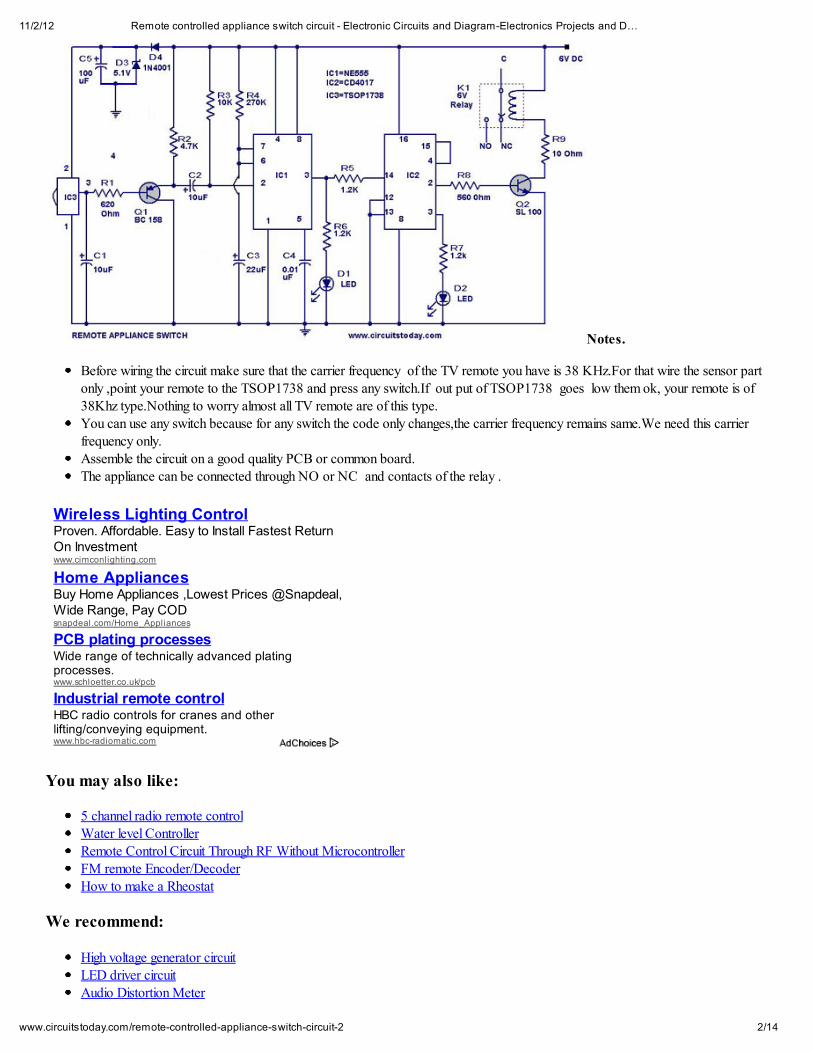
IR remote sensor IC TSOP 1738 is used for recieving the signal. Normally when no signal is falling on IC3 the output of it will behigh.This makes Q1 OFF.When a signal of 38 KHz from the TV remote falls on the IC3 its output goes low.This makes Q1 conduct anda negative pulse is obtained at pin 2 of IC 1 NE 555.Due to this IC1 wired as a monostable multivibrator produces a 4 Sec long highsignal at its out put.This high out put is the clock for IC 2 which is wired as a Flipflop and of , its two outputs pin 3 goes low and pin 2goes high.The high output at pin 2 is amplified to drive the relay .For the next signal the outputs of IC2 toggles state. Result, we get arelay toggling on each press on the remote.Any appliance connected to this circuit can be switched ON or OFF.
Circuit Diagram with Parts List .
Ads by Google Circuit Board Circuit Diagrams Electronic Circuit Circuit Design
Electric PumpWholesale Suppliers & Factory Price Contact Directly & Get Live Quotes!
www.Alibaba.com
11/2/12 Remote controlled appliance switch circuit - Electronic Circuits and Diagram-Electronics Projects and D…
2/14www.circuitstoday.com/remote-controlled-appliance-switch-circuit-2
Notes.
Before wiring the circuit make sure that the carrier frequency of the TV remote you have is 38 KHz.For that wire the sensor part
only ,point your remote to the TSOP1738 and press any switch.If out put of TSOP1738 goes low them ok, your remote is of38Khz type.Nothing to worry almost all TV remote are of this type.You can use any switch because for any switch the code only changes,the carrier frequency remains same.We need this carrierfrequency only.Assemble the circuit on a good quality PCB or common board.
The appliance can be connected through NO or NC and contacts of the relay .
You may also like:
5 channel radio remote controlWater level ControllerRemote Control Circuit Through RF Without MicrocontrollerFM remote Encoder/DecoderHow to make a Rheostat
We recommend:
High voltage generator circuitLED driver circuitAudio Distortion Meter
Wireless Lighting ControlProven. Affordable. Easy to Install Fastest ReturnOn Investmentwww.cimconlighting.com
Home AppliancesBuy Home Appliances ,Lowest Prices @Snapdeal,Wide Range, Pay CODsnapdeal.com/Home_Appliances
PCB plating processesWide range of technically advanced platingprocesses.www.schloetter.co.uk/pcb
Industrial remote controlHBC radio controls for cranes and otherlifting/conveying equipment.www.hbc-radiomatic.com
11/2/12 Remote controlled appliance switch circuit - Electronic Circuits and Diagram-Electronics Projects and D…
3/14www.circuitstoday.com/remote-controlled-appliance-switch-circuit-2
Custom Search
PIC 16F877 – Architecture and Memory Organization
Diac
Search
Posted in Home Circuits, Remote CircuitsTags: circuit design, circuit diagram, hobby circuits, hobby projects, Home Circuits
Leave a Reply
Name (required)
Mail (will not be published) (required)
Website
Submit Comment
61 Responses to “Remote controlled appliance switch circuit”
Girish says:October 9, 2012 at 1:39 am
May i use this circuit to switch on and off the led flashers using tv remote, pls advice me
Replychris says:October 7, 2012 at 12:20 pm
i have used this circuit for 7 years for light circuit and still run perfect. All you need is a stabiole power source.
Replyzivumile says:October 1, 2012 at 3:43 am
Sir can this project be used in any appliances like heater
ReplyAbhilash says:August 24, 2012 at 2:53 am
sir,can we make remote for epson ebx9 projector to conrol power switch….?
ReplySUGANYA says:July 24, 2012 at 3:46 am

plz i want the pin diagram of these three IC.
Replycant find tsop1738 in ecg data book says:May 27, 2012 at 6:49 am
ic tsop1738 cant be find ,Pls assit.
Replyjaga says:August 24, 2012 at 4:05 am
I think its a sensor. Instead of it u can use television remote sensor.
ReplyBenjamin says:February 24, 2012 at 11:33 pm
I’ much interested in building this circuit, but the parts aren’t so easy to come by in my country.Do u have any advice to how I can get these parts
Replykamaal says:February 23, 2012 at 7:56 pm
i want 2 fan and 3 tube light circuit and programme
Replymanoj kumar says:February 23, 2012 at 5:49 am
hi sir,i want to connect this ckt to my fan and operate with my remote,is it possible are not,if so how?
ReplySaurabh says:January 5, 2012 at 9:17 am
heyy admin,this one is cool
but if i want to make an ir remote controlled switch board for more than one on/off appliances using a microcontroller, then in thatcase could you please provide me with the circuit diagram of that.and necessary details of thatthanks
Reply
Baffa Bello dry says:January 5, 2012 at 3:28 am
Hi lam happy for this cct.l made it for switching elect. bulbs in my room. Thankyou
Replyseetharaman says:November 15, 2011 at 1:41 pm
Hi Abdul the 6volts relay contacts are rated for 220Volt AC and for rated current see the relay contact ratings or use a 6 voltsrelay wih required contact voltage and current rating.
11/2/12 Remote controlled appliance switch circuit - Electronic Circuits and Diagram-Electronics Projects and D…
5/14www.circuitstoday.com/remote-controlled-appliance-switch-circuit-2
ReplyAbdul Jakul says:November 14, 2011 at 7:06 pm
Is this can load directly to 22Ov for on/off switch?i plan to used it for light switch…
Reply
seetharaman says:November 5, 2011 at 9:39 am
Hi Hemanth use the common and Normally open contact of the relay to operate any off/on control of any equipment.
Replyhemanth says:November 4, 2011 at 8:48 am
please tell me relay connectionsmy i.d:[email protected]
Reply
hemanth says:November 4, 2011 at 8:46 am
please tell me the relay connectionshow should i connect relay here
ReplyJavid ali says:November 3, 2011 at 3:36 am
it’s realy a good circuit. I’m made it in the combetition. Thank u for circuits today & seetharaman
Replyseetharaman says:
November 1, 2011 at 4:02 pm
Hi Javid 1 to 1.5mm bit can beused. Use 12 volt relay increase the supply to 12 volts DC add a 560 ohms 1/4 between supply atthe relay point to IC2 Pin16 in the positive rail. This will take care of the rest of the circuits
ReplyJavid ali says:November 1, 2011 at 7:30 am
I want a kind help pleas. I don’t get 6V relay any where. I got only 12V relay. What i do. No much time for my combetition.
ReplyJavid ali says:
November 1, 2011 at 12:58 am
Which is the bit size used for the driller for making holes on PCB?
ReplyJavid ali says:October 31, 2011 at 11:15 pm
Ya.its amaizing & i gained more.
11/2/12 Remote controlled appliance switch circuit - Electronic Circuits and Diagram-Electronics Projects and D…
6/14www.circuitstoday.com/remote-controlled-appliance-switch-circuit-2
Replyseetharaman says:October 31, 2011 at 12:30 pm
Hi Javid the following article will be useful to you please follow the linkhttp://www.riccibitti.com/pcb/pcb.htm
ReplyJavid ali says:October 31, 2011 at 7:34 am
I want to make a PCB by KCl3.what r the terms followed?Plz help me by giving definition/giving web site address.
ReplyJavid ali says:October 29, 2011 at 10:40 pm
Ok .thank u very much.
Replyseetharaman says:October 29, 2011 at 7:29 pm
Hi Javid you can use 560 ohms or 680 ohms. it will not matter. the unit will work.
ReplyJavid ali says:October 29, 2011 at 8:39 am
Hai… I lik to make this circuit for a combetition. But i have no 620 ohm resistance. May i use 220 ohm,390 ohm & 10 ohm inseries?
Reply
seetharaman says:September 1, 2011 at 9:26 am
Hi Visus Please note for 1838 1 is output 3 is supply and 2 is common. Kindly rewire as above it will become alright.
Replyvisus says:August 30, 2011 at 8:48 pm
hye ! I m using tsop 1838 an when i press tv remote switch ,d output goes to 3.94 v frm 4.9 , cn i use this in this crcuit n if notwhat actually is active low output of pin 3 frm tsop 1738 when ir is sensed
Replyseetharaman says:August 3, 2011 at 3:41 am
Hi Maaniq you can use your ir remote with the above circuit. with the relay contacy you can switch on / off any appliance withinthe rated capacity of its contacts(relay).
ReplyMaaniq says:August 2, 2011 at 12:18 am
@seetharaman and all., i have two questions., can u plz resolve for me…..?
11/2/12 Remote controlled appliance switch circuit - Electronic Circuits and Diagram-Electronics Projects and D…
7/14www.circuitstoday.com/remote-controlled-appliance-switch-circuit-2
1.can i use 38 khz remote transmitter for sony IR-D15A….?2.can i control my home appliances like fan or light ? BY driving a relay with the output of IR-D15A., will it drive a relay? 5vSPDT relay., so tat i can control my home appliances?plz reply …….
Replyseetharaman says:July 7, 2011 at 9:08 am
Hi Nik you can try the following 15 channel controller Sony Ic ID-D15A with universal remote control.http://www.rentron.com/Files/IR-D15A.pdf
Replyseetharaman says:July 7, 2011 at 8:41 am
Hi Nik you may try the following project for 4 channels http://www.circuitstoday.com/remote-control-circuit-through-rf-without-microcontroller
Replynik says:July 6, 2011 at 2:43 am
can we make whole lighting scheme remote controlled by using 1 universal remote???
Replyjahfarali says:June 17, 2011 at 10:25 am
Good, It is working but it cannot use for tube lights..it will detect tube lights..
ReplyAbraham says:May 26, 2011 at 6:53 am
i want to make this circuit please give me full description
ReplyRajib says:February 28, 2011 at 10:26 pm
I am going to make it.
Replyadmin says:February 22, 2011 at 9:33 pm
i made a small modifcation to this circuit. Diode D4 is added so that the parts of the circuit other than the IC3 donot load the zenerdiode.
ReplySaravanan says:February 22, 2011 at 9:13 am
Hi.i gave connection as per circuit diagram…but my zener diode is heating….and LED 1 is not glowing,while LED 2 is glowing,and no output,
11/2/12 Remote controlled appliance switch circuit - Electronic Circuits and Diagram-Electronics Projects and D…
8/14www.circuitstoday.com/remote-controlled-appliance-switch-circuit-2
plz help to solve my problem guys..
ReplyStudentCRO says:November 30, 2010 at 12:52 pm
This is what I got for my school project and we must make it in PROTEL design system (1994) so anyone got this draw on thatprogram and possible to send me file? thx
ReplySeetharaman says:November 30, 2010 at 9:37 am
Hi Rakesh this can be used for any on/off application. for varying speed you have to add 4017 etc.
Replyrakesh says:November 29, 2010 at 9:57 pm
sir
it is possible to celling fan which is to be used in home appliances can you say that this circuit is applicable or not if it is not possiblethen send a appropriate circut for remote control celling fan thanking you
Replymohammed says:October 8, 2010 at 1:19 am
hai frnds plz send me many projects.i wait for ur reply
ReplyImteaz says:August 23, 2010 at 6:25 am
To Seetharaman,Thanks for the tips. By solving false triggering problem this circuit may be used for multipurpose switching.
Replyshreya says:August 22, 2010 at 10:47 pm
Hi seetharamansubject: 100watt sub-wooferi shorted R9 & R10 the temperature of transistors decreased but Q7 is getting hotter than Q5 why ?
Replyseetharaman says:August 22, 2010 at 9:41 am
Hi Imteaz you can connect 100uF and a reverse biased diode in parallel with relay coil K1, this should solve your problem as theback EMF from relay coil is false triggering your IC.
ReplyImteaz says:August 21, 2010 at 10:57 am
11/2/12 Remote controlled appliance switch circuit - Electronic Circuits and Diagram-Electronics Projects and D…
9/14www.circuitstoday.com/remote-controlled-appliance-switch-circuit-2
I was trying to make a touch switch by 555 and 4017. But when I used relay i faced false triggering of 4017. Is this circuit freefrom false triggering?
ReplyArifuddin Sheik says:July 13, 2010 at 9:36 pm
IC2 is CD4017. If you have any doubts regarding this circuit. mail me to [email protected]
Replyrajesh says:June 9, 2010 at 5:57 am
how i can rised the voltage from 1.5v to 12v.give me circuit diagram.help me pls.
Replyusama says:March 14, 2010 at 10:14 am
plz tell me the number of ic2
ReplyAarish shahab says:February 22, 2010 at 12:41 am
i am going to work on this project………!!!
ReplyMALECKO says:February 11, 2010 at 11:07 am
can i put this circuit on 9V
ReplyMALECKO says:February 9, 2010 at 1:18 am
can i put TSOP1138 instead of TSOP1738? please reply on this e-mail [email protected]
Replyjay says:September 20, 2009 at 2:51 pm
can i connect light,fan,refregirator to this single circuit and operate.if we cannot what is the alternative to operate all the house hold elements.some body please help me in making a house hold appliances circuit.
Replyadmin says:September 20, 2009 at 11:54 pm
the load that can be connected to this circuit depends on the current capacity of the relay that you are using.You can get only one switching action from this circuit.More that one devices cannot be independently switched.
ReplyVicky says:August 23, 2009 at 7:12 am
its is working i have made this but the main problem iam facing is that when i apply voltage to the circuit it energises the relas mean

11/2/12 Remote controlled appliance switch circuit - Electronic Circuits and Diagram-Electronics Projects and D…
10/14www.circuitstoday.com/remote-controlled-appliance-switch-circuit-2
it gets triggered every but its working i want to remove this triggering on power apply help me plz
Replyayan says:July 15, 2009 at 9:17 am
yaaaaa , its workinggggggggg
ReplyArifuddin says:July 12, 2009 at 6:27 pm
I made this circuit. Its 100% working. But it is a complicated one. I designed my circuit slightly changing the above one which is
very easy to make and working. contact me at [email protected] the schematic. hope you all like it..
Replyayan says:July 11, 2009 at 5:11 am
hi , i am going to make this circuit today .can anybody tell me about this , i mean is it really working without any problem ? because i am a new comer . can u plz tell thatthis is tested ok ?
my mail is [email protected]
Replyadmin says:July 14, 2009 at 12:27 am
This circuit will work.Please proceed
Replyvali says:January 5, 2009 at 3:58 am
super
Reply
Get Daily Updates via Email
Enter your email Subscribe
Latest Articles
Digital thermometer using 8051Most Popular Electronic CircuitsVoltmeter using 8051AVR Microcontroller Tutorial – The complete guide to learn AVRControl structures and statements in C and C++Quick Sorting algorithm with example code in C/C++/Java languages
11/2/12 Remote controlled appliance switch circuit - Electronic Circuits and Diagram-Electronics Projects and D…
11/14www.circuitstoday.com/remote-controlled-appliance-switch-circuit-2
Insertion sorting algorithm with example in C/C++/Java languages
Bit rate Vs Baud rate – the common misconceptionSelection Sort in C/C++/Java programming languagesDifference between Procedure Oriented(POP) and Object Oriented Programming(OOP)
Categories
101-Announcements555 Timer IC80518051 projectsAmplifier CircuitsArduino
Audio CircuitsAutomotive CircuitsAVRBasic ElectricityBattery CircuitsC plus plusC ProgrammingCable TV CircuitsCamera TechnologyClipping and Clamping CircuitsClocking & Timer CircuitsConversion CircuitsCounter CircuitsCountersDigital Electronics
Abs SensorHigh-Performance Semiconductors. AndSensor Integrated Circuits.www.allegromicro.com
123 Cross Crosses
See crosses for 123 Cross 185M parts with F-F-F alternativeswww.sil iconexpert.com
TI's Signal Conditioners
Deliver the Industry's Highest Performance atthe Lowest Power.ti.com
11/2/12 Remote controlled appliance switch circuit - Electronic Circuits and Diagram-Electronics Projects and D…
12/14www.circuitstoday.com/remote-controlled-appliance-switch-circuit-2
Education & TrainingElectronic ComponentsElectronic Keys & LocksElectronics BooksElectronics JobsEmbedded SystemsEquipment ReviewsEvents
Fan CircuitsFilter Circuits
Fire AlarmFun & Game Circuits
Gadget ReviewsHam Radio Circuits
High Voltage CircuitsHistory
Home CircuitsIndustrial Circuits
InstrumentsIntegrated Circuits
InvertersLab Manuals
LED relatedLight Related
Lighting CircuitsMicrocontrollers
Mobile Phone RelatedMotor Related
Nanotechnology
OscillatorsPeripheral Interface Controller (PIC)
Power Controller CircuitsPower Electronics
Power SuppliesProject Ideas
ProjectsProximity Detectors
Radio CircuitsRadio Transmitters
RelaysRemote Circuits
ReviewsRobotics
RTOSSecurity & Saftey
Sensor CircuitsSignal Conditioners
Signal GeneratorsSpeed Controller Circuits
State space analysisSwitching Circuits
Tech NewsTelephone Related
Television Related
Temperature Related

11/2/12 Remote controlled appliance switch circuit - Electronic Circuits and Diagram-Electronics Projects and D…
13/14www.circuitstoday.com/remote-controlled-appliance-switch-circuit-2
Test & Measurement Circuits
Testing ComponentsThree phase circuits
Timer CircuitsTone generator circuits
Tools and SoftwaresTransmitters
TutorialsUPS
USB CircuitsVideos
VLSIVoltage Regulators
Like Us on Facebook
Elmer Jay Foster Kely Harry Sy ed Danish Nagesh
Natty O scar GerardoSadiiq Haji A mith Shruthi
Circuitstoday.com on Facebook
Like 9,252
9,252 people like Circuitstoday.com.
Facebook social plugin
Recent Comments
sam on Simple Water Level Indicator
verma ji on Sawtooth Wave Generatorharshit on Remote Operated Spy Robot Circuit
shoair on Mobile incoming call indicatorharshit on Remote Operated Spy Robot Circuit
shoair on Air flow detector circuit.rollly on 60W inverter using transistors
Jamal on 2 x 60 W audio amplifier circuitJamal on 2 x 60 W audio amplifier circuit
niki on 24V lead acid battery charger circuitniki on Air flow detector circuit.
rebin on Digital voltmeter using ICL7107
novice 29 on 24V lead acid battery charger circuitAppah Evans on 2 km FM transmitter
seetharaman on Air flow detector circuit.
Pages
About
Advertise With UsAuthors
Datasheets
11/2/12 Remote controlled appliance switch circuit - Electronic Circuits and Diagram-Electronics Projects and D…
14/14www.circuitstoday.com/remote-controlled-appliance-switch-circuit-2
Electronic Circuit SymbolsLab Manuals
Electronic Circuits LabMicrocontroller lab
Microprocessor LabPrivacy Policy
Project Contests
Project KitsSitemap
Testing Components
Popular Tags
555 IC 555 timer Audio Amplifier Circuits Audio circuits circuit design circuit diagram ElectronicCircuits Electronic Components Electronic Instruments Filter Circuits hobby circuits hobby projects Home Circuits IC
Integrated Circuits Most Popular Circuits Nanotechnology NE555 timer Oscillators PIC Power Amplifiers Power Supplies Radio Circuits SCR
Simple Electronics Projects Tech News Thyristors Tutorials VLSI Voltage Regulators
Most Discussed
150 Watt amplifier circuit100 Watt sub woofer amplifier.
Automatic LED Emergency Light-Modified VersionMains Operated LED Circuit
Suggest a Topic to Publish & Win a 8GB Pen Drive2 km FM transmitter
Automatic LED Emergency Light
Copyright © 2007 - 2011 Circuitstoday.com Designed by Web Design Cochin