Embed Size (px)
Citation preview
Angel® Concentrated Platelet Rich Plasma (cPRP) System -
Operator’s Manual
Software Version 1.21
DFU-0262-3 Revision 0 06/2020

This page intentionally left blank
Overview
Angel® cPRP System Operator’s Manual i
Table of Contents Before You Get Started
Introduction .............................................................................................................................................. vii Indications for Use ................................................................................................................................... vii Contraindications for Use ......................................................................................................................... vii Warnings .................................................................................................................................................. vii Precautions ............................................................................................................................................... x Symbols .................................................................................................................................................. xiii Service Information ................................................................................................................................. xiv Return of Used Product .......................................................................................................................... xiv
Chapter 1: Overview
Product Description ................................................................................................................................ 1-1 Description of the Angel® Concentrated Platelet Rich Plasma (cPRP) System .................................... 1-1
How the Angel System Works .................................................................................................. 1-1 Angel System Components ...................................................................................................... 1-2
Shipping and Storage ............................................................................................................................ 1-3 Installation .............................................................................................................................................. 1-3
Special tools, equipment and environmental requirements ...................................................... 1-4 Visual Inspection ....................................................................................................................... 1-4 Unpacking/Assembly ................................................................................................................ 1-4 Operational Checks .................................................................................................................. 1-6 Setting the Date and Time ........................................................................................................ 1-6
Chapter 2: Installing the Angel cPRP Processing Set
The Angel Processing Set or Disposable Set ........................................................................................ 2-1 Description ................................................................................................................................ 2-1 Warnings and Precautions ........................................................................................................ 2-3
Setup and Blood/Bone Marrow Aspirate Preparation ............................................................................ 2-3 Turning on the Angel System .................................................................................................... 2-4
Chapter 3: Processing
Before You Begin ................................................................................................................................... 3-1 Loading the Angel System ........................................................................................................ 3-1 Collecting the Blood or Mixture of Blood and Bone Marrow ..................................................... 3-1
Running the Separation Process ........................................................................................................... 3-2 Saving Case Data .................................................................................................................................. 3-6
Entering Optional Case Data Fields ......................................................................................... 3-7 Modifying Optional Data Field Values ....................................................................................... 3-8
Overview
ii Angel® cPRP System Operator’s Manual
Selecting Past Cases ................................................................................................................ 3-9 Saving a Tally Table to a USB Storage Device ...................................................................... 3-10 Saving a Case Log .................................................................................................................. 3-11
Touch Screen User Interface ............................................................................................................... 3-12 Start Screen ............................................................................................................................ 3-12 Run Screen ............................................................................................................................. 3-14 End of Cycle Screen ............................................................................................................... 3-16 End of Case Screen ................................................................................................................ 3-17 Menu Screen ........................................................................................................................... 3-18 Information Screen .................................................................................................................. 3-22 Past Cases Screen ................................................................................................................. 3-23 Output Screen ......................................................................................................................... 3-24 Stop Button ............................................................................................................................. 3-26 Power Loss ............................................................................................................................. 3-27
Chapter 4: Programmability Option
Creating Custom Protocols .................................................................................................................... 4-1 Entering Values and Text .......................................................................................................... 4-2 Creating a New Protocol ........................................................................................................... 4-3 Editing the Parameters of a Protocol ........................................................................................ 4-4 Restoring the Parameters of a Protocol .................................................................................... 4-4 Renaming a Protocol ................................................................................................................ 4-5 Changing the Wakeup Protocol ................................................................................................ 4-5 Deleting a Protocol .................................................................................................................... 4-5
The Protocols Tab .................................................................................................................................. 4-6 1. Protocol Buttons .................................................................................................................... 4-7 2. Protocol Parameters and Buttons ......................................................................................... 4-7 3. Protocol Pull-Down Button .................................................................................................... 4-8 4. Close Button.......................................................................................................................... 4-9 5-6. Up and Down Arrow Buttons ............................................................................................. 4-9 7. Information Button ................................................................................................................. 4-9
Chapter 5: Troubleshooting
Alarms and Notifications ........................................................................................................................ 5-1 Troubleshooting the Save Process ........................................................................................................ 5-6 Troubleshooting the Software Update Process ..................................................................................... 5-6 Other Operational & Troubleshooting Tips ............................................................................................ 5-7
Chapter 6: Routine Care
New Software ......................................................................................................................................... 6-1 New Software Screen ............................................................................................................................ 6-4 Visual Inspection .................................................................................................................................... 6-5
Overview
Angel® cPRP System Operator’s Manual iii
Routine Care .......................................................................................................................................... 6-5 Non-Routine Care .................................................................................................................................. 6-7
In the Event of a Serious Fluid (Blood) Spill ............................................................................. 6-7 Dissassembling & Cleaning the Centrifuge Parts & Centrifuge Well ........................................ 6-7 Preventive Maintenance Requirements .................................................................................... 6-9 Fuse Replacement .................................................................................................................. 6-10
Chapter 7: Technical Data
Specifications ......................................................................................................................................... 7-1 Performance Characteristics ..................................................................................................... 7-1 Physical Characteristics ............................................................................................................ 7-1 Environmental Limitations ......................................................................................................... 7-1
Chapter 8: Other Commercial Matters
Limitation of Liability .................................................................................................................. 8-1 Technical documentation .......................................................................................................... 8-1 Technical safety standards ....................................................................................................... 8-1 Identification of manufacturer .................................................................................................... 8-3
Overview
iv Angel® cPRP System Operator’s Manual
List of Figures
Chapter 1: Overview
Figure 1-1 Front-view of the Angel System ........................................................................................... 1-2 Figure 1-2 Rear-view of Angel System .................................................................................................. 1-2 Figure 1-3 Start Screen .......................................................................................................................... 1-3 Figure 1-4 Load Screen ......................................................................................................................... 1-6 Figure 1-5 Date and Time Settings ........................................................................................................ 1-6
Chapter 2: Installing the Disposables
Figure 2-1 Angel® Processing Set ......................................................................................................... 2-2 Figure 2-2 Rear-view of Angel System .................................................................................................. 2-4 Figure 2-4 Centrifuge Stator Arm Aligned with Variable Volume Separation Chamber ........................ 2-9
Chapter 3: Processing
Figure 3-1 Load Screen ......................................................................................................................... 3-1 Figure 3-2 Start Screen .......................................................................................................................... 3-2 Figure 3-3 Run Screen ........................................................................................................................... 3-3 Figure 3-4 End of Cycle Screen ............................................................................................................. 3-3 Figure 3-5 End of Case Screen ............................................................................................................. 3-4 Figure 3-6 “Tally” tab of the Menu Screen ............................................................................................. 3-7 Figure 3-7 Keyboard Screen (Text Entry) .............................................................................................. 3-8 Figure 3-8 Past Cases Screen ............................................................................................................... 3-9 Figure 3-9 Output Screen .................................................................................................................... 3-10 Figure 3-10 Start Screen ...................................................................................................................... 3-12 Figure 3-11 Run Screen ....................................................................................................................... 3-14 Figure 3-12 End of Cycle Screen ......................................................................................................... 3-16 Figure 3-13 End of Case Screen ......................................................................................................... 3-17 Figure 3-14 “Language” tab of the Menu Screen ................................................................................. 3-19 Figure 3-15 Tally Tab of the Menu Screen .......................................................................................... 3-20 Figure 3-16 “Settings” tab of the Menu Screen .................................................................................... 3-21 Figure 3-17 Information Screen ........................................................................................................... 3-22 Figure 3-18 Past Cases Screen ........................................................................................................... 3-23 Figure 3-19 Output Screen .................................................................................................................. 3-24 Figure 3-20 Empty Screen ................................................................................................................... 3-26 Figure 3-21 Correct Valve Assembly Handle Position ......................................................................... 3-27
Overview
Angel® cPRP System Operator’s Manual v
Chapter 4: Programmability Option
Figure 4-1 The “Protocols” tab ............................................................................................................... 4-2 Figure 4-2 The Keyboard Screen (Protocol Name) ............................................................................... 4-2 Figure 4-3 “Protocols” tab of the Menu Screen ...................................................................................... 4-6
Chapter 6: Routine Care
Figure 6-1 Unlock Code Screen ............................................................................................................. 6-2 Figure 6-2 Software Validated Screen ................................................................................................... 6-3 Figure 6-3 Install Screen ........................................................................................................................ 6-3 Figure 6-4 New Software Screen ........................................................................................................... 6-4 Figure 6-7 Removing the Centrifuge Adaptor Plate ............................................................................... 6-8 Figure 6-8 Removing the Spring Plate and Springs .............................................................................. 6-9 Figure 6-9 Cleaning On and Around the Adaptor Base ......................................................................... 6-9 Figure 6-10 Fuse Replacement: Pry Open Cover ............................................................................... 6-10 Figure 6-11 Fuse Replacement: Slide Out Holders ............................................................................. 6-10
This is not a warranty document. For all warranty information, including disclaimers, exclusions, terms, conditions and related provisions refer to the “Arthrex U.S. Product Warranty” section of the Arthrex, Inc. website, found at www.arthrex.com whose provisions are incorporated herein by reference.

Overview
vi Angel® cPRP System Operator’s Manual
This page intentionally left blank
Overview
Angel® cPRP System Operator’s Manual vii
Before You Get Started Introduction
The Angel® Concentrated Platelet Rich Plasma (cPRP) System (Angel System) is designed to separate autologous blood or a mixture of blood and bone marrow. The primary blood components that the Angel System separates and collects are red blood cells (RBC), platelet poor plasma (PPP) and platelet rich plasma (PRP).
The Angel System utilizes a Variable Volume Separation Chamber that is capable of processing between 40 mL to 180 mL of anticoagulated whole blood or mixture of blood and bone marrow in a single cycle. A maximum of 180 mL can be processed in up to three (3) cycles for each disposable Angel® Concentrated Platelet Rich Plasma (cPRP) System Processing Set (Angel Processing Set or Disposable Set).
This manual is intended for users of the Angel System. The procedures recommended in this Operator’s Manual have been developed and tested to provide safe, reliable and efficient operation of the Angel System. It is important that the operator thoroughly understand the information in this Operator’s Manual before attempting to use the Angel System.
Indications for Use
The Arthrex Angel System is indicated to be used intraoperatively at the point of care for the safe and rapid preparation of autologous platelet poor plasma and platelet concentrate (platelet rich plasma) from a small sample of peripheral blood or a small sample of a mixture of peripheral blood and bone marrow. The platelet poor plasma and platelet rich plasma are mixed with autograft and/or allograft bone prior to application to a bony defect for improving handling characteristics.
Disclaimer: Platelet Rich Plasma prepared from a mixture of whole blood and bone marrow may contain higher levels of plasma free hemoglobin than Platelet Rich Plasma prepared from whole blood.
Contraindications for Use
The Angel System may be contraindicated in cases where there are active systemic infections or systemic heparinization.
Warnings
1. This device is intended to be used by a trained medical professional. A trained operator should be present at all times to operate and monitor the Angel System during processing.
2. Biohazard waste, such as needles and contaminated surgical equipment, should be safely disposed of in accordance with the institutions policy. Disposal of used equipment and/or used Angel Processing Sets should be performed in accordance with federal, state, and local regulations. These materials should be considered biohazardous. Universal precautions for blood-borne pathogens
Overview
viii Angel® cPRP System Operator’s Manual
should be practiced (e.g., gloves, Personal Protective Equipment (PPE), etc.) when disposing of these items.
3. The use of operating or maintenance procedures other than those published by the manufacturer, or the use of accessory devices not recommended by the manufacturer may result in poor equipment performance.
4. The manufacturer will not be responsible for patient safety or equipment performance if the Angel System is operated in a manner other than specified in this manual. Medical individuals performing the operations described in this manual must be properly trained and qualified.
5. Any equipment modifications must be performed by qualified persons and be approved by the manufacturer in writing.
6. All electrical installations must comply with all applicable local electrical codes and the manufacturer’s specifications.
7. This equipment, when used with the specified data accessories, meets the following standards identified below. The user does not need to provide additional efforts regarding electromagnetic emissions or immunity:
• IEC 60601-1-2 o EN 55011, Class A standards o EN 61000
• Canadian Warning: This equipment is intended for use by healthcare professionals only. The Angel System may cause radio interference or may disrupt the operation of nearby equipment. It may be necessary to take mitigation measures, such as re-orienting or relocating the Angel System or shielding the location.
o Use sterile technique when setting up the Angel Processing Set o Thoroughly clean and disinfect the donation site o Use sterile technique whenever handling autologous
blood products 8. To avoid the risk of electrical shock, this equipment must only be connected to a
supply mains with protective earth. Do not use alternate power plugs or adapters that disconnect the safety ground.
9. The operator should never touch the USB port on the Angel System, while at the same time making contact with the patient, as potential for electrical shock may result.
10. Place the Angel System on a flat, stable surface. Never try to move the Angel System while the device is in operation. Failure to comply may result in damage to the Angel System and injury may result.
11. Do not use the Angel System in the presence of flammable agents as an explosion and/or fire may result.
12. Do not contact any moving parts of the centrifuge or pump while the Angel System is in operation. Injury may result.
13. Only Angel Processing Sets are approved for patient use with the Angel System.
14. Do not use the Angel Processing Set if the sterile packaging barrier has been broken.
15. Carefully examine the Angel Processing Set for damage prior to use. Should any evidence of damage to the Processing Set be evident, do not use the Angel Processing Set.
16. Carefully observe the Angel Processing Set for leaks during use. Leakage may
Overview
Angel® cPRP System Operator’s Manual ix
result in loss of sterility of the device or loss of blood product.
17. Use of this product for pediatric patients is at the discretion of a physician. Blood withdrawal from a pediatric patient should be performed in the presence and at the direction of a physician to prevent significant reduction of the circulating blood volume.
18. When collecting and processing autologous blood products, it is recommended that the following precautions be followed to insure that the autologous product is not contaminated:
• Use sterile technique when setting up the Angel Processing Set
• Thoroughly clean and disinfect the donation site
• Use sterile technique whenever handling autologous blood products 19. The whole blood or the mixture of blood and bone marrow must be anticoagulated
before it can be processed for separation. Inadequate anticoagulation may result in clotting, interfering with the processing of the blood products. Blood containing clots will not pass through the syringe-activated valve located on the Whole Blood Compartment of the Three-Compartment Reservoir Bag.
20. Failure to properly load the Centrifuge Plate prior to processing, may lead to exposure to blood and blood-borne pathogens.
21. If centrifugation is discontinued before the completion of a processing cycle, the Variable Volume Separation Chamber is pressurized and presents the risk for exposure to blood and blood-borne pathogens if the Variable Volume Separation Chamber is not properly removed. Please refer to “Stop Button” on page 3-26 for emptying a Variable Volume Separation Chamber containing blood.
22. If a power loss occurs, and there is blood or a mixture of blood and bone marrow in the Variable Volume Separation Chamber, follow the instructions under “Power Loss” on page 3-27.
23. Failure to properly secure the Luer Lock Syringe to the Valve Assembly may result in a leakage of fluids.
24. Do not connect the patient directly to the Three-Compartment Reservoir Bag. A direct connection to the patient could lead to vascular damage, shock, or an air embolism.
25. Do not place objects in or on the pump during pump rotation. Damage to the machine and Angel Processing Set may occur.
26. If the Angel System fails to operate as intended, do not use the separated blood products.
27. The platelet rich plasma is not intended for transfusion.
28. The Angel System is not intended to be used by the patient. As such a mains power switch is not available to the user. In case of an emergency, power from the unit can be removed by unplugging the unit from the electrical socket.
29. Only devices or cables meeting IEC 60950 and IEC 60601-1 should be connected to the USB Port. Failure to do so may result in operator shock. All cables used in conjunction with the device should be no longer than 1 m (3 ft.) in length. Operators connecting other devices to the USB port must ensure compliance to the system requirements of IEC 60601-1.
30. Operators connecting other devices to the USB Port must ensure compliance to the system requirements of IEC 60601-1. Connection of other devices could result in previously unidentified risk to the patient, operator, or third parties. It is responsibility of the operator to identify, analyze, evaluate, and control any
Overview
x Angel® cPRP System Operator’s Manual
previously unidentified risks.
31. The Potential Equalization Conductor (PEC) is a common ground point with the device that is connected directly to the power input ground. The PEC is used for the Angel System Electrical Safety Testing. The PEC is not to be used by the operator to connect additional medical devices to the system during installation, or use of the system.
32. Caution: Federal law restricts this device to sale by or on the order of a physician.
33. Serious incidents should be reported to Arthrex Inc., or an in-country representative, and to the health authority where the incident occurred.
Precautions
1. Due to the possibility of operator exposure to blood-borne pathogens (such as HIV, hepatitis viruses, bacteria, etc.), Universal Precautions for blood-borne pathogens should be practiced (e.g., gloves, Personal Protective Equipment (PPE), etc.).
2. The Angel Processing Set is intended for single patient use only. a. Each set can be used on the same patient for up to three sequential
processing cycles. b. Once used, it should be disposed of properly. c. Do not resterilize any part of this Processing Set. d. The Processing Set should not be re-used for another patient.
3. Carefully read this Operator’s Manual for complete instructions.
4. Use a neutral-pH enzymatic detergent when cleaning the Platelet Sensor. Do not use bleach, abrasive materials or solvents, as they may cause damage to the sensor.
5. Do not place external light sources within 1 meter (3 ft.) of the unit when operating the Angel System. External light sources may interfere with the operation of the Platelet Sensor and may result in reduced processing efficiency.
6. Do not immerse the Pump Rotor in cleaning solution or autoclave, as this may result in damage.
7. Follow the installation instructions included in this manual, prior to first use.
8. To prevent risk of electrical shock, shut OFF the power and unplug the system from the electrical outlet before performing cleaning procedures or replacing the fuses.
9. Immediately report any of the following conditions to the Arthrex, Inc. Customer Service. Don’t use the Angel System until corrective action has been taken:
• Damaged or worn Power Cord Assembly, plug or receptacle • Switches that are loose, or do not operate properly • A system that has been subjected to physical damage • A system that has electrically shocked anyone • A system that appears to be overheating
10. It is the responsibility of the health care institution to adequately prepare and identify the product for return shipment. Do not return products that have been exposed to blood-borne infectious diseases.
11. When removing the Angel Processing Set from its packaging, check to ensure that
Overview
Angel® cPRP System Operator’s Manual xi
the three (3) Threaded Luer Caps (see Figure 2-1, item 5) on each Compartment (Whole Blood, RBC and PPP) are securely tightened prior to installation into the Angel System.
12. Failure to properly load the Angel Processing Set, per the enclosed instructions may adversely affect the performance of the system.
13. Luer Lock Syringes should be used with the Angel Processing Set.
14. Pressing the Stop Button during separation may reduce processing efficiency.
15. The physician ordering the collection of PRP shall use discretion when any of the following conditions exist:
• sepsis • preoperative hematocrit less than 30% • preoperative platelet count less than 195,000 per µL • hemodynamically unstable • prolonged clotting times • recent use of anti-platelet drugs • inability to maintain stable oncotic pressure
16. Only attach the Power Cord to a power outlet that is properly grounded.
17. Replace the mains fuses only with fuses of the same type and rating.
18. There are no user-serviceable parts inside this device. To avoid the risk of electrical shock, do not remove the cover. Refer all servicing to qualified service personnel.
19. Federal law (USA) restricts this device to sale by or on the order of a physician.
20. If the case data are relevant for patient’s treatment, it will always be necessary to use other Hospital standard measuring instruments.
21. The user of the Angel System is responsible for the monitoring of the system performance, when using custom protocols.
22. The Angel System has been tested and verified to meet applicable Electromagnetic Compatibly (EMC) and Electrical Safety standards, when put into service according to this manual. (Refer to Chapter 7 - “Environmental Limitations”.)
23. The Angel System has the ability to save data using a USB connection.
Note: Only devices or cables meeting IEC 60950 and IEC 60601-1 should be connected to the USB Port and/or Ethernet Port(if present). Failure to do so may result in operator shock. All cables used in conjunction with the device should be no longer than 1 m (3 ft.) in length. Operators connecting other devices to the USB ports must ensure compliance to the system requirements of IEC 60601-1.
24. The pins of the USB connector should not be touched, and connection to the port should not be made unless ESD (Electrostatic discharge) precautionary procedures are used.
25. Surgeons are advised to review the product-specific surgical technique prior to performing any surgery. Arthrex provides detailed surgical techniques in print, video, and electronic formats. The Arthrex website also provides detailed surgical technique information and demonstrations. Or, contact your Arthrex representative for an onsite demonstration

Overview
xii Angel® cPRP System Operator’s Manual
Overview
Angel® cPRP System Operator’s Manual xiii
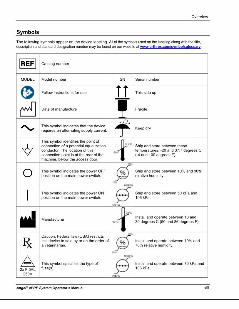
Symbols The following symbols appear on the device labeling. All of the symbols used on the labeling along with the title, description and standard designation number may be found on our website at www.arthrex.com/symbolsglossary.
Catalog number
MODEL Model number SN Serial number
Follow instructions for use
This side up
Date of manufacture
Fragile
This symbol indicates that the device requires an alternating supply current.
Keep dry
This symbol identifies the point of connection of a potential equalization conductor. The location of this connection point is at the rear of the machine, below the access door.
Ship and store between these temperatures: -20 and 37.7 degrees C (-4 and 100 degrees F).
This symbol indicates the power OFF position on the main power switch.
Ship and store between 10% and 90% relative humidity.
This symbol indicates the power ON position on the main power switch.
Ship and store between 50 kPa and 106 kPa.
Manufacturer
Install and operate between 10 and 30 degrees C (50 and 86 degrees F).
Caution: Federal law (USA) restricts this device to sale by or on the order of a veterinarian.
Install and operate between 10% and 70% relative humidity.
2x F 5AL
250V
This symbol specifies the type of fuse(s).
Install and operate between 70 kPa and 106 kPa.
Overview
xiv Angel® cPRP System Operator’s Manual
Service Information
The company accepts responsibility for the safety, reliability and performance of this equipment only if operational procedures, calibrations and repairs are performed by appropriately qualified persons; if all equipment modifications are authorized in writing by the company and performed by appropriately qualified persons; if the electrical installation of the relevant room complies with all applicable local electrical codes; and if the equipment is used in accordance with the published instructions for use. If you require technical assistance, please contact your Customer Service Representative. Arthrex, Inc. 1370 Creekside Blvd Naples, FL 34108 USA Telephone: + 1 800-391-8599 [email protected] www.arthrex.com
Return of Used Product
If for any reason this product must be returned to Arthrex, Inc., a Returned Materials Authorization (RMA) number is required from Arthrex, Inc. prior to shipping it. If the product has been in contact with blood or body fluids, it must be thoroughly cleaned and disinfected before packing. It should be shipped in either the original carton, or an equivalent carton, to prevent damage during shipment; and it should be properly labeled with the RMA number and an explanation of the biohazardous nature of the contents. Instructions for cleaning and materials, including appropriate shipping containers, proper labeling and an RMA number may be obtained from the Arthrex, Inc. Customer Service (+1 800-391-8599) or [email protected].
PRECAUTION
It is the responsibility of the health care institution to adequately prepare and identify the product for its return. Do not return products that have been exposed to blood-borne infectious diseases.
The shipping address for returned goods is: Arthrex, Inc. 14550 Plantation Road Fort Myers, FL 33912 Telephone: + 1 800-391-8599 [email protected] www.arthrex.com

Overview
Angel® cPRP System Operator’s Manual xv
This page intentionally left blank

Overview
Angel® cPRP System Operator’s Manual 1-1
Chapter 1: Overview Product Description
The Angel® Concentrated Platelet Rich Plasma (cPRP) System (Angel System) consists of a blood processing system and disposable products used for separation of whole blood or a mixture of blood and bone marrow into red cells, platelet poor plasma, and platelet rich plasma. The disposable Angel® Concentrated Platelet Rich Plasma (cPRP) System Processing Set is designed for single-patient use. The Variable Volume Separation Chamber allows the clinician to process from 40 mL to 180 mL of autologous whole blood or a mixture of blood and bone marrow in a single cycle. A maximum of 180 mL can be processed in up to three (3) cycles for each disposable Angel Processing Set.
Description of the Angel® Concentrated Platelet Rich Plasma (cPRP) System
How the Angel System Works
The Angel System processes a determined volume of anticoagulated whole blood or a mixture of blood and bone marrow from a patient and separates the blood/bone marrow into its primary components: red blood cells (RBC), platelet poor plasma (PPP), and platelet rich plasma (PRP). The basic steps are: Blood Collection: The whole blood or a mixture of blood and bone marrow is drawn from a patient and mixed with a citrate anticoagulant. The collected whole blood/bone marrow is mixed in a 7:1 ratio (7 parts whole blood to 1 part citrate anticoagulant (ACD-A)). Please refer to the Instructions for Use for the Angel® Concentrated Platelet Rich Plasma (cPRP) Processing Set for details regarding Blood Collection for further details. Processing: The Angel Processing Set utilizes a Variable Volume Separation Chamber (40 mL to 180 mL) which allows the clinician to determine the amount of preoperative blood/bone marrow volume to be processed. Each Angel Processing Set can be used for up to three processing cycles. Once the anticoagulated whole blood or mixture of blood and bone marrow has been dispensed into the Whole Blood Compartment of the reservoir bag, the clinician selects the desired volume of autologous whole blood/bone marrow to process and presses the “Start” Button on the Touch Screen Display. The Angel System will fill the Variable Volume Separation Chamber with the pre-determined volume of anticoagulated whole blood or a mixture of blood and bone marrow, separate the whole blood/bone marrow through centrifugation, and collect the primary blood components (RBC, PPP, and PRP) in their respective collection compartments. Administration: Reinfusion of blood components is under the control and supervision of the physician in charge. Follow your institution’s blood administration protocol for appropriate handling and labeling of blood components.
Overview
1-2 Angel® cPRP System Operator’s Manual
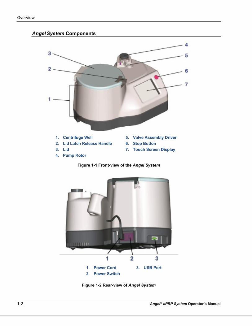
Angel System Components
1. Centrifuge Well 5. Valve Assembly Driver 2. Lid Latch Release Handle 6. Stop Button 3. Lid 7. Touch Screen Display 4. Pump Rotor
Figure 1-1 Front-view of the Angel System
1. Power Cord 3. USB Port 2. Power Switch
Figure 1-2 Rear-view of Angel System
Overview
Angel® cPRP System Operator’s Manual 1-3
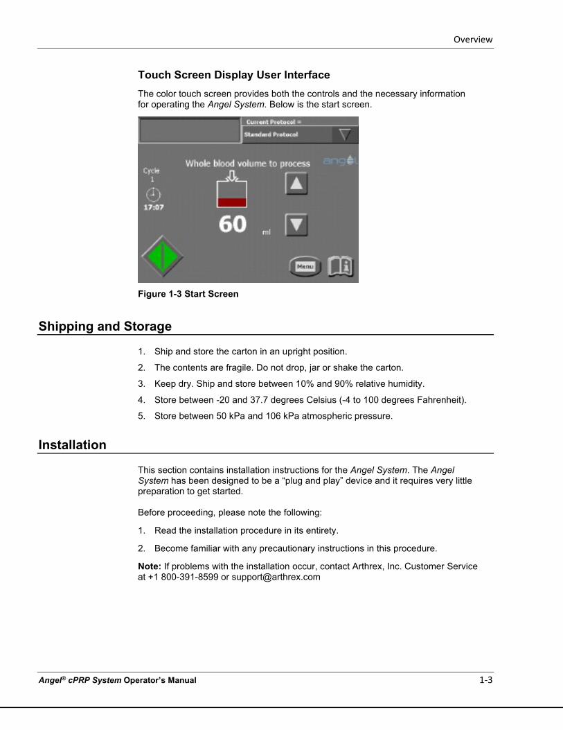
Touch Screen Display User Interface The color touch screen provides both the controls and the necessary information for operating the Angel System. Below is the start screen.
Figure 1-3 Start Screen
Shipping and Storage
1. Ship and store the carton in an upright position.
2. The contents are fragile. Do not drop, jar or shake the carton.
3. Keep dry. Ship and store between 10% and 90% relative humidity.
4. Store between -20 and 37.7 degrees Celsius (-4 to 100 degrees Fahrenheit).
5. Store between 50 kPa and 106 kPa atmospheric pressure.
Installation
This section contains installation instructions for the Angel System. The Angel System has been designed to be a “plug and play” device and it requires very little preparation to get started. Before proceeding, please note the following:
1. Read the installation procedure in its entirety.
2. Become familiar with any precautionary instructions in this procedure.
Note: If problems with the installation occur, contact Arthrex, Inc. Customer Service at +1 800-391-8599 or [email protected]
Overview
1-4 Angel® cPRP System Operator’s Manual
Special tools, equipment and environmental requirements
There are no special tools required to install and set up this device.
PRECAUTION Prior to the first use, follow the installation instructions included in this manual.
Visual Inspection
Upon delivery, ensure that the unit’s shipping carton has not been damaged. If there are signs of damage, a formal complaint must be made at once to the transport agent. Check the unit carefully to ensure that there are no missing parts or visible signs of damage. Any complaints, together with a detailed account of the problems identified must be immediately reported to either the local representative or directly to Arthrex, Inc. at the following address:
Arthrex, Inc. Telephone: + 1 800-391-8599 1370 Creekside Blvd [email protected] Naples, FL 34108 USA www.arthrex.com
Unpacking/Assembly
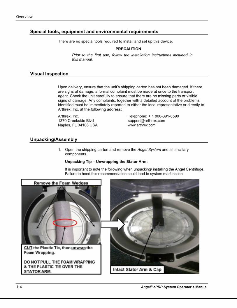
1. Open the shipping carton and remove the Angel System and all ancillary components.
Unpacking Tip – Unwrapping the Stator Arm:
It is important to note the following when unpacking/ installing the Angel Centrifuge. Failure to heed this recommendation could lead to system malfunction:
Overview
Angel® cPRP System Operator’s Manual 1-5
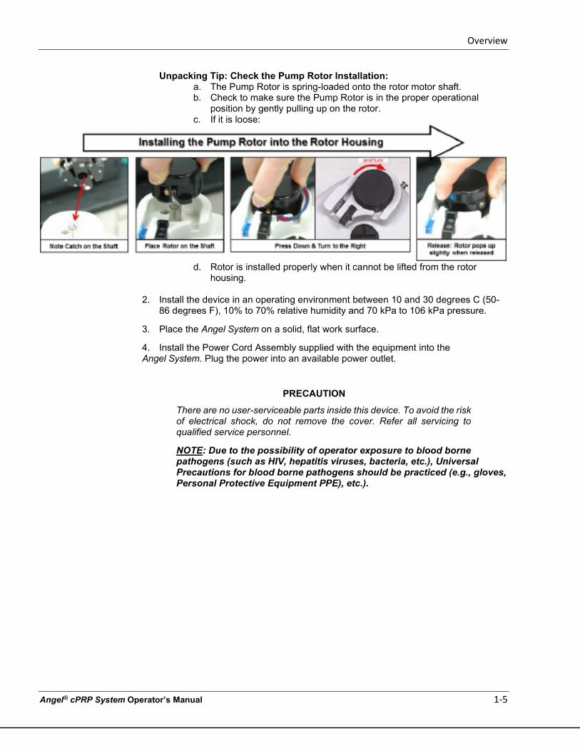
Unpacking Tip: Check the Pump Rotor Installation: a. The Pump Rotor is spring-loaded onto the rotor motor shaft. b. Check to make sure the Pump Rotor is in the proper operational
position by gently pulling up on the rotor. c. If it is loose:
d. Rotor is installed properly when it cannot be lifted from the rotor
housing. 2. Install the device in an operating environment between 10 and 30 degrees C (50-
86 degrees F), 10% to 70% relative humidity and 70 kPa to 106 kPa pressure.
3. Place the Angel System on a solid, flat work surface.
4. Install the Power Cord Assembly supplied with the equipment into the Angel System. Plug the power into an available power outlet.
PRECAUTION
There are no user-serviceable parts inside this device. To avoid the risk of electrical shock, do not remove the cover. Refer all servicing to qualified service personnel.
NOTE: Due to the possibility of operator exposure to blood borne pathogens (such as HIV, hepatitis viruses, bacteria, etc.), Universal Precautions for blood borne pathogens should be practiced (e.g., gloves, Personal Protective Equipment PPE), etc.).
Overview
1-6 Angel® cPRP System Operator’s Manual
Operational Checks
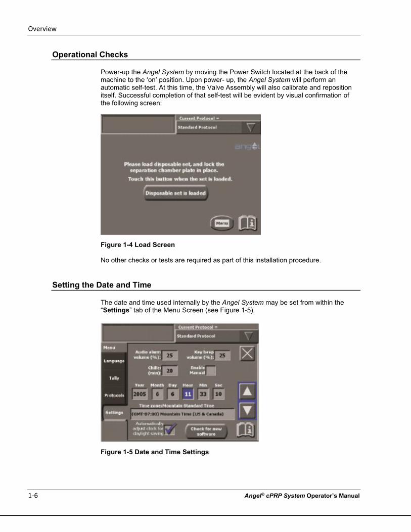
Power-up the Angel System by moving the Power Switch located at the back of the machine to the ‘on’ position. Upon power- up, the Angel System will perform an automatic self-test. At this time, the Valve Assembly will also calibrate and reposition itself. Successful completion of that self-test will be evident by visual confirmation of the following screen:
Figure 1-4 Load Screen
No other checks or tests are required as part of this installation procedure.
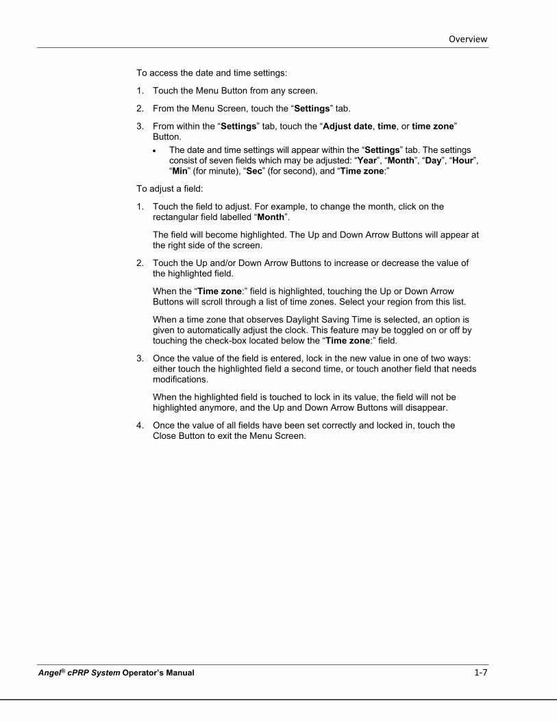
Setting the Date and Time
The date and time used internally by the Angel System may be set from within the “Settings” tab of the Menu Screen (see Figure 1-5).
Figure 1-5 Date and Time Settings
Overview
Angel® cPRP System Operator’s Manual 1-7
To access the date and time settings:
1. Touch the Menu Button from any screen.
2. From the Menu Screen, touch the “Settings” tab.
3. From within the “Settings” tab, touch the “Adjust date, time, or time zone” Button. • The date and time settings will appear within the “Settings” tab. The settings
consist of seven fields which may be adjusted: “Year”, “Month”, “Day”, “Hour”, “Min” (for minute), “Sec” (for second), and “Time zone:”
To adjust a field:
1. Touch the field to adjust. For example, to change the month, click on the rectangular field labelled “Month”.
The field will become highlighted. The Up and Down Arrow Buttons will appear at the right side of the screen.
2. Touch the Up and/or Down Arrow Buttons to increase or decrease the value of the highlighted field.
When the “Time zone:” field is highlighted, touching the Up or Down Arrow Buttons will scroll through a list of time zones. Select your region from this list.
When a time zone that observes Daylight Saving Time is selected, an option is given to automatically adjust the clock. This feature may be toggled on or off by touching the check-box located below the “Time zone:” field.
3. Once the value of the field is entered, lock in the new value in one of two ways: either touch the highlighted field a second time, or touch another field that needs modifications.
When the highlighted field is touched to lock in its value, the field will not be highlighted anymore, and the Up and Down Arrow Buttons will disappear.
4. Once the value of all fields have been set correctly and locked in, touch the Close Button to exit the Menu Screen.

Overview
1-8 Angel® cPRP System Operator’s Manual
This page intentionally left blank
Installing the Angel cPRP Processing Set
Angel® cPRP System Operator’s Manual 2-1
Chapter 2: Installing the Angel cPRP Processing Set The Angel Processing Set or Disposable Set
Description
The Angel Processing Set consists of a pre-connected Variable Volume Separation Chamber, a tubing set with a Platelet Sensor / Valve Assembly, and a Three-Compartment Reservoir Bag for the collection of blood products (whole blood, red blood cells, and platelet poor plasma). The Angel Processing Set also contains a 20 mL Luer Lock Syringe for the collection of platelet rich plasma (PRP), two 60 mL Specimen Cups for use in a sterile field, a whole blood bag spike adapter, Male-Female Luer Plugs, and labels for collected blood components. Major Components (see Figure 2-1 below): Variable Volume Separation Chamber: The Angel Processing Set uses a Variable Volume Separation Chamber that can process from 40 mL to 180 mL of anticoagulated autologous whole blood or a mixture of blood and bone marrow in a single cycle. Each Angel Processing Set is capable of processing up to three (3) cycles. The top section of the Variable Volume Separation Chamber (the hard plastic component) is the Separation Chamber Plate. The Separation Chamber Plate is used to seat the Variable Volume Separation Chamber in the centrifuge. Platelet Cuvette / Valve Assembly: The Platelet Cuvette / Valve Assembly contains three major components: (1) the Platelet Cuvette, (2) the Pump Loop Tubing and (3) the Rotating Valve. The Platelet Cuvette is seated into the Platelet Sensor and is used to optimize the collection of the separated blood components. The Pump Loop Tubing is inserted around the pump, which moves volume from the Whole Blood Compartment of the Three-Compartment Reservoir Bag to the Variable Volume Separation Chamber and from the Variable Volume Separation Chamber to the various collection compartments for the separated blood products (PRP, PPP and RBC). The Rotating Valve rotates throughout the processing cycle to direct the whole blood, the mixture of blood and bone marrow, or its separated components through the appropriate pathway. The Platelet Cuvette / Valve Assembly has been designed so that the operator can easily install it while insuring that the Platelet Cuvette is properly seated in the Platelet Sensor and that the Rotating Valve is properly seated on the Valve Assembly Driver.
Installing the Angel cPRP Processing Set
2-2 Angel® cPRP System Operator’s Manual
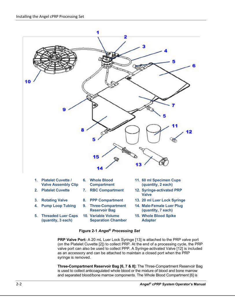
1. Platelet Cuvette / Valve Assembly Clip
6. Whole Blood Compartment
11. 60 ml Specimen Cups (quantity, 2 each)
2. Platelet Cuvette 7. RBC Compartment 12. Syringe-activated PRP Valve
3. Rotating Valve 8. PPP Compartment 13. 20 ml Luer Lock Syringe 4. Pump Loop Tubing 9. Three-Compartment
Reservoir Bag 14. Male-Female Luer Plug
(quantity, 7 each) 5. Threaded Luer Caps
(quantity, 3 each) 10. Variable Volume
Separation Chamber 15. Whole Blood Spike
Adapter
Figure 2-1 Angel® Processing Set
PRP Valve Port: A 20 mL Luer Lock Syringe [13] is attached to the PRP valve port (on the Platelet Cuvette [2]) to collect PRP. At the end of a processing cycle, the PRP valve port can also be used to collect PPP. A Syringe-activated Valve [12] is included as an accessory and can be attached to maintain a closed port when the PRP syringe is removed. Three-Compartment Reservoir Bag [6, 7 & 8]: The Three-Compartment Reservoir Bag is used to collect anticoagulated whole blood or the mixture of blood and bone marrow and separated blood/bone marrow components. The Whole Blood Compartment [6] is
Installing the Angel cPRP Processing Set
Angel® cPRP System Operator’s Manual 2-3
used as a reservoir for collected anticoagulated whole blood from a patient. The clinician may use syringes or whole blood bags to collect the anticoagulated whole blood or the mixture of blood and bone marrow from a patient. The RBC Compartment [7] is used to collect the concentrated red cells at the end of the processing cycle. The PPP Compartment [8] is used to collect platelet poor plasma; the PPP is the first blood component collected after separation has been completed. Syringe-activated valves are used to access the PPP and Whole Blood Compartments of the Three-Compartment Reservoir Bag. Other items included in the Angel Processing Set: 20 mL Luer Lock Syringe [13]: The 20 mL Luer Lock Syringe is used for the collection of platelet rich plasma. However, the Syringe-activated PRP Valve will accommodate most luer fitting syringes. 60 mL Specimen Cups [11] (2 ea.): Two 60 mL Specimen Cups for use in a sterile field. Male/Female Luer Plugs [14]: The male/female luer plugs are used during and at the end of procedure to seal open luer lock connections. Whole Blood Bag Spike Adapter [15]: The Whole Blood Spike Adapter is used to transfer the blood or mixture of blood and bone marrow from a whole blood bag to the Whole Blood Compartment of the Three-Compartment Reservoir Bag. Labels: Appropriate labels for labeling the collected whole blood/bone marrow and separated components. The contents of this set have been sterilized by ethylene oxide gas and have non-pyrogenic fluid pathways.
Warnings and Precautions
Please see “Warnings” on page vii in the section “Before You Get Started”; see “Precautions” on page x in the same section.
Setup and Blood/Bone Marrow Aspirate Preparation
IMPORTANT: Due to the possibility of operator exposure to blood borne pathogens (such as HIV, hepatitis viruses, bacteria, etc.), Universal Precautions for blood borne pathogens should be practiced (e.g., gloves, Personal Protective Equipment (PPE), etc.). The Angel Processing Set is intended for single patient use only.
• Each set can be used on the same patient for up to three sequential processing cycles. • Once used, it should be disposed of properly. • Do not resterilize any part of this Processing Set. • The Processing Set should not be re-used for another patient.
Installing the Angel cPRP Processing Set
2-4 Angel® cPRP System Operator’s Manual
Turning on the Angel System
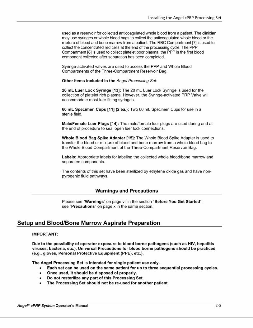
1. Turn on the Angel System by pressing the Power Switch on the back of the machine. The message, “Self-test in progress. Please stand by” will be displayed on the Angel System’s Touch Screen Display, and then the machine will move the Valve Assembly Driver to the loading position.
1. Power Switch
Figure 2-2 Rear-view of Angel System
Initial Setup
NOTES: Note: Loading the Variable Volume Separation Chamber [9] should always be the first step in the setup process. Loading the Variable Volume Separation Chamber and pressing down on the Separation Chamber Plate will remove excess air volume from the chamber. If excess air is not removed, the Separation Chamber Plate will not load properly. An instructional animation for the installation of the Angel Processing Set (described in the steps below) is available from the Information Screen immediately after powering on the Angel System. (Refer to the “Information Screen” on page 3-22.)
An online instructional video entitled “Arthrex Angel® System Processing Procedure Demonstration” is also available at www.arthrex.com
Hyperlink: https://www.arthrex.com/resources/pdv/10z8V9nyoEmWbQFEnkcW7Q/arthrex-angel-system-processing-procedure-demonstration
Installing the Angel cPRP Processing Set
Angel® cPRP System Operator’s Manual 2-5
With the Angel System turned on, do the following:
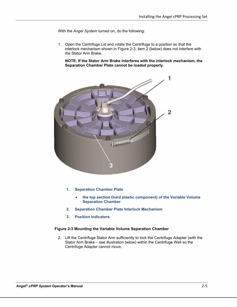
1. Open the Centrifuge Lid and rotate the Centrifuge to a position so that the interlock mechanism shown in Figure 2-3, item 2 (below) does not interfere with the Stator Arm Brake.
NOTE: If the Stator Arm Brake interferes with the interlock mechanism, the Separation Chamber Plate cannot be loaded properly.
1. Separation Chamber Plate
• the top section (hard plastic component) of the Variable Volume Separation Chamber
2. Separation Chamber Plate Interlock Mechanism
3. Position Indicators
Figure 2-3 Mounting the Variable Volume Separation Chamber
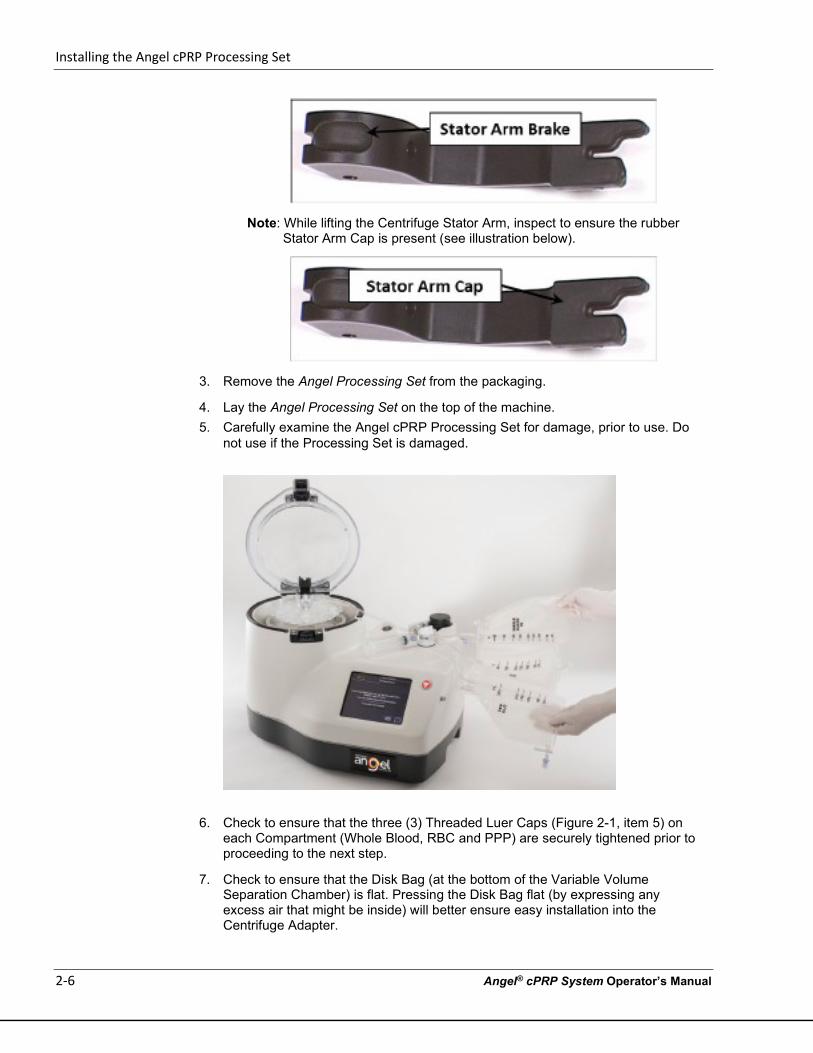
2. Lift the Centrifuge Stator Arm sufficiently to lock the Centrifuge Adapter (with the
Stator Arm Brake – see illustration below) within the Centrifuge Well so the Centrifuge Adapter cannot move.
Installing the Angel cPRP Processing Set
2-6 Angel® cPRP System Operator’s Manual
Note: While lifting the Centrifuge Stator Arm, inspect to ensure the rubber Stator Arm Cap is present (see illustration below).
3. Remove the Angel Processing Set from the packaging.
4. Lay the Angel Processing Set on the top of the machine. 5. Carefully examine the Angel cPRP Processing Set for damage, prior to use. Do
not use if the Processing Set is damaged.
6. Check to ensure that the three (3) Threaded Luer Caps (Figure 2-1, item 5) on each Compartment (Whole Blood, RBC and PPP) are securely tightened prior to proceeding to the next step.
7. Check to ensure that the Disk Bag (at the bottom of the Variable Volume Separation Chamber) is flat. Pressing the Disk Bag flat (by expressing any excess air that might be inside) will better ensure easy installation into the Centrifuge Adapter.
Installing the Angel cPRP Processing Set
Angel® cPRP System Operator’s Manual 2-7
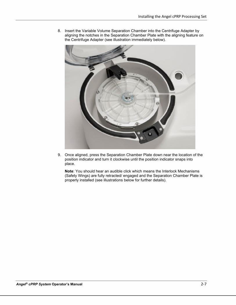
8. Insert the Variable Volume Separation Chamber into the Centrifuge Adapter by aligning the notches in the Separation Chamber Plate with the aligning feature on the Centrifuge Adapter (see illustration immediately below).
9. Once aligned, press the Separation Chamber Plate down near the location of the position indicator and turn it clockwise until the position indicator snaps into place.
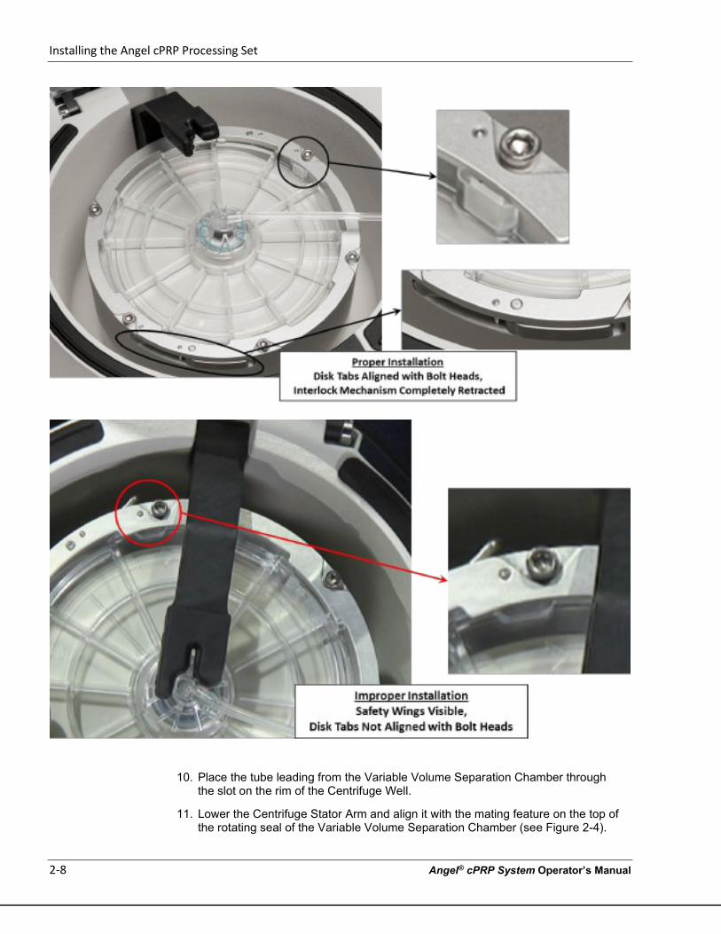
Note: You should hear an audible click which means the Interlock Mechanisms (Safety Wings) are fully retracted/ engaged and the Separation Chamber Plate is properly installed (see illustrations below for further details).
Installing the Angel cPRP Processing Set
2-8 Angel® cPRP System Operator’s Manual
10. Place the tube leading from the Variable Volume Separation Chamber through
the slot on the rim of the Centrifuge Well.
11. Lower the Centrifuge Stator Arm and align it with the mating feature on the top of the rotating seal of the Variable Volume Separation Chamber (see Figure 2-4).
Installing the Angel cPRP Processing Set
Angel® cPRP System Operator’s Manual 2-9
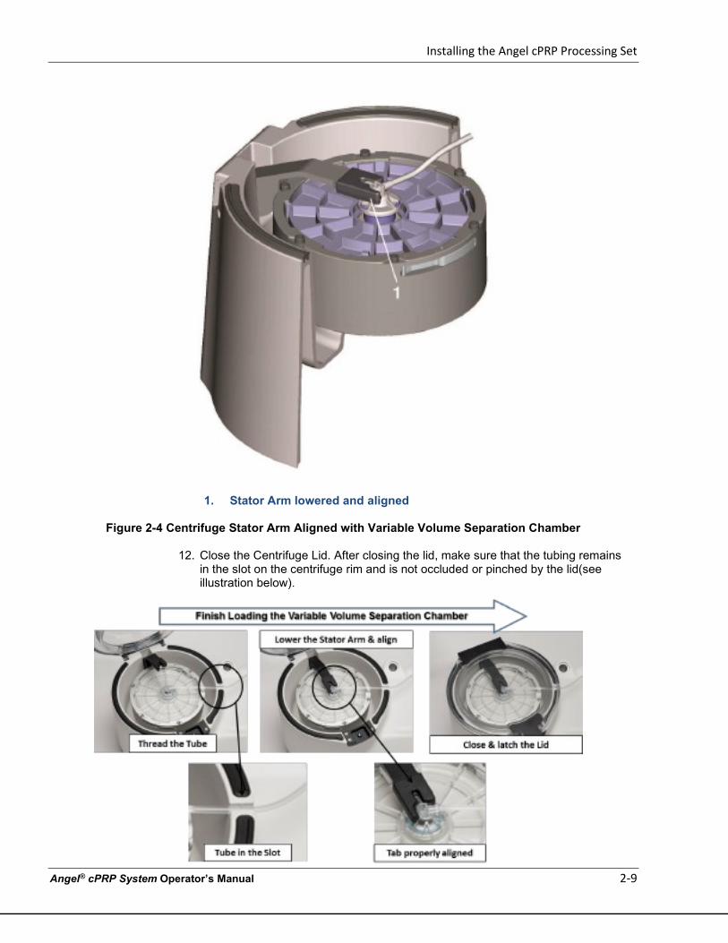
1. Stator Arm lowered and aligned
Figure 2-4 Centrifuge Stator Arm Aligned with Variable Volume Separation Chamber
12. Close the Centrifuge Lid. After closing the lid, make sure that the tubing remains in the slot on the centrifuge rim and is not occluded or pinched by the lid(see illustration below).
Installing the Angel cPRP Processing Set
2-10 Angel® cPRP System Operator’s Manual
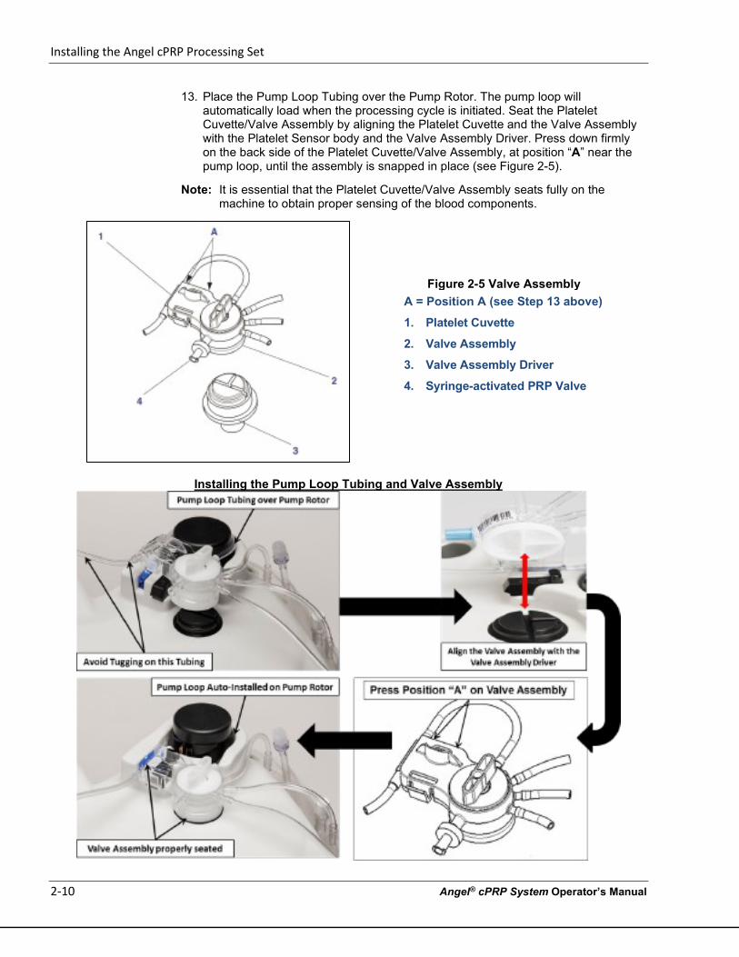
13. Place the Pump Loop Tubing over the Pump Rotor. The pump loop will automatically load when the processing cycle is initiated. Seat the Platelet Cuvette/Valve Assembly by aligning the Platelet Cuvette and the Valve Assembly with the Platelet Sensor body and the Valve Assembly Driver. Press down firmly on the back side of the Platelet Cuvette/Valve Assembly, at position “A” near the pump loop, until the assembly is snapped in place (see Figure 2-5).
Note: It is essential that the Platelet Cuvette/Valve Assembly seats fully on the machine to obtain proper sensing of the blood components.
Installing the Pump Loop Tubing and Valve Assembly
Figure 2-5 Valve Assembly A = Position A (see Step 13 above)
1. Platelet Cuvette
2. Valve Assembly
3. Valve Assembly Driver
4. Syringe-activated PRP Valve
Installing the Angel cPRP Processing Set
Angel® cPRP System Operator’s Manual 2-11
14. Hang the Three-Compartment Reservoir Bag on the two support pins located on
the side of the Angel System.
15. Remove the breather cap from the PRP valve port located on the Valve Assembly. If desired, attach the Syringe-activated Valve to the PRP valve port.
16. Attach the 20 mL Luer Lock Syringe (or alternate syringe) to the PRP valve port.
Installation Tip: Cycle the Plunger of the 20-mL Luer Lock (PRP) Syringe
a. Immediately prior to attaching the PRP syringe to the manifold, cycle the PRP plunger (e.g., prime the plunger), the return it to its original [closed] position), then install the syringe to the manifold.
b. The syringe plunger may adhere to the syringe barrel during storage (e.g., plunger sticks or is too tight) which may restrict the proper flow of the PRP into the syringe during the PRP harvest.
c. Taking this precautionary measure helps to avoid this from happening.
Note: The luer on the PRP valve port will accommodate most luer-lock syringes.
Installing the Angel cPRP Processing Set
2-12 Angel® cPRP System Operator’s Manual
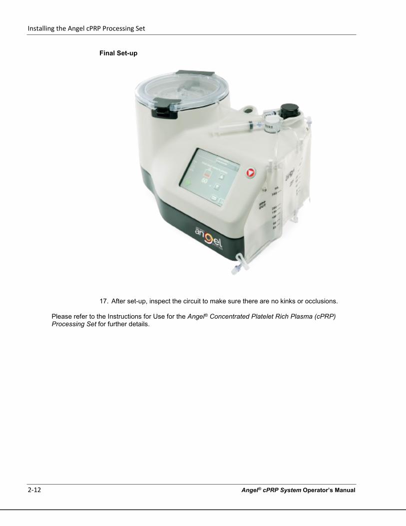
Final Set-up
17. After set-up, inspect the circuit to make sure there are no kinks or occlusions.
Please refer to the Instructions for Use for the Angel® Concentrated Platelet Rich Plasma (cPRP) Processing Set for further details.
Processing
Angel® cPRP System Operator’s Manual 3-1
Chapter 3: Processing Before You Begin
Loading the Angel System
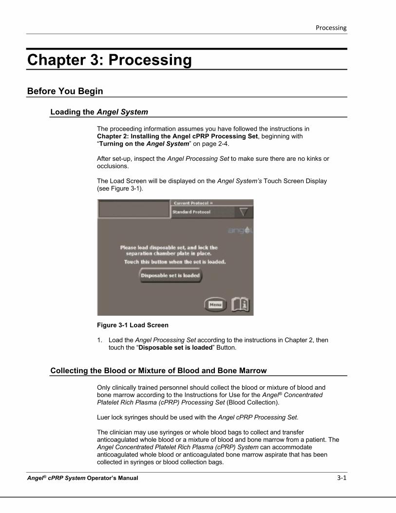
The proceeding information assumes you have followed the instructions in Chapter 2: Installing the Angel cPRP Processing Set, beginning with “Turning on the Angel System” on page 2-4. After set-up, inspect the Angel Processing Set to make sure there are no kinks or occlusions. The Load Screen will be displayed on the Angel System’s Touch Screen Display (see Figure 3-1).
Figure 3-1 Load Screen
1. Load the Angel Processing Set according to the instructions in Chapter 2, then touch the “Disposable set is loaded” Button.
Collecting the Blood or Mixture of Blood and Bone Marrow
Only clinically trained personnel should collect the blood or mixture of blood and bone marrow according to the Instructions for Use for the Angel® Concentrated Platelet Rich Plasma (cPRP) Processing Set (Blood Collection). Luer lock syringes should be used with the Angel cPRP Processing Set. The clinician may use syringes or whole blood bags to collect and transfer anticoagulated whole blood or a mixture of blood and bone marrow from a patient. The Angel Concentrated Platelet Rich Plasma (cPRP) System can accommodate anticoagulated whole blood or anticoagulated bone marrow aspirate that has been collected in syringes or blood collection bags.
Processing
3-2 Angel® cPRP System Operator’s Manual
The adhesive labels included in the Angel Processing Set packaging can be used to label & uniquely identify the patient’s Processing Set, collected whole blood/bone marrow aspirate and the separated blood/ bone marrow aspirate components, if desired. Note: Before processing more than one cycle of blood or the mixture of blood and bone marrow, agitate the Whole Blood Compartment of the reservoir bag to mix the remaining blood, providing a more uniform collection of blood components.
Running the Separation Process
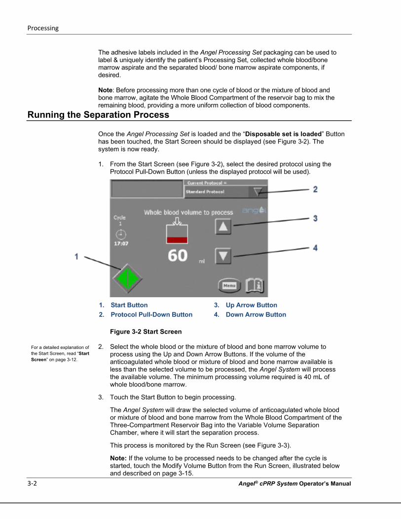
Once the Angel Processing Set is loaded and the “Disposable set is loaded” Button has been touched, the Start Screen should be displayed (see Figure 3-2). The system is now ready.
1. From the Start Screen (see Figure 3-2), select the desired protocol using the
Protocol Pull-Down Button (unless the displayed protocol will be used).
1. Start Button 3. Up Arrow Button 2. Protocol Pull-Down Button 4. Down Arrow Button
Figure 3-2 Start Screen
2. Select the whole blood or the mixture of blood and bone marrow volume to
process using the Up and Down Arrow Buttons. If the volume of the anticoagulated whole blood or mixture of blood and bone marrow available is less than the selected volume to be processed, the Angel System will process the available volume. The minimum processing volume required is 40 mL of whole blood/bone marrow.
3. Touch the Start Button to begin processing.
The Angel System will draw the selected volume of anticoagulated whole blood or mixture of blood and bone marrow from the Whole Blood Compartment of the Three-Compartment Reservoir Bag into the Variable Volume Separation Chamber, where it will start the separation process.
This process is monitored by the Run Screen (see Figure 3-3).
Note: If the volume to be processed needs to be changed after the cycle is started, touch the Modify Volume Button from the Run Screen, illustrated below and described on page 3-15.
For a detailed explanation of the Start Screen, read “Start Screen” on page 3-12.
Processing
Angel® cPRP System Operator’s Manual 3-3
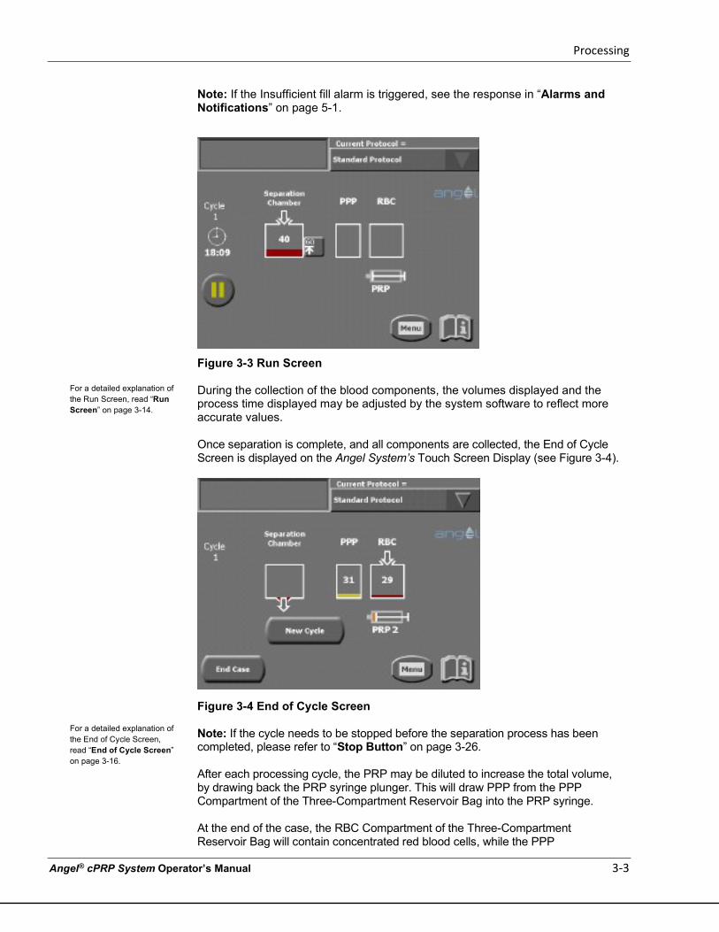
Note: If the Insufficient fill alarm is triggered, see the response in “Alarms and Notifications” on page 5-1.
Figure 3-3 Run Screen
During the collection of the blood components, the volumes displayed and the process time displayed may be adjusted by the system software to reflect more accurate values. Once separation is complete, and all components are collected, the End of Cycle Screen is displayed on the Angel System’s Touch Screen Display (see Figure 3-4).
Figure 3-4 End of Cycle Screen
Note: If the cycle needs to be stopped before the separation process has been completed, please refer to “Stop Button” on page 3-26. After each processing cycle, the PRP may be diluted to increase the total volume, by drawing back the PRP syringe plunger. This will draw PPP from the PPP Compartment of the Three-Compartment Reservoir Bag into the PRP syringe. At the end of the case, the RBC Compartment of the Three-Compartment Reservoir Bag will contain concentrated red blood cells, while the PPP
For a detailed explanation of the Run Screen, read “Run Screen” on page 3-14.
For a detailed explanation of the End of Cycle Screen, read “End of Cycle Screen” on page 3-16.
Processing
3-4 Angel® cPRP System Operator’s Manual
Compartment of the Three-Compartment Reservoir Bag will contain platelet poor plasma.
Note: Before processing more than one cycle of blood or the mixture of blood and bone marrow, agitate the Whole Blood Compartment of the reservoir bag to mix the remaining blood, providing a more uniform collection of blood components.
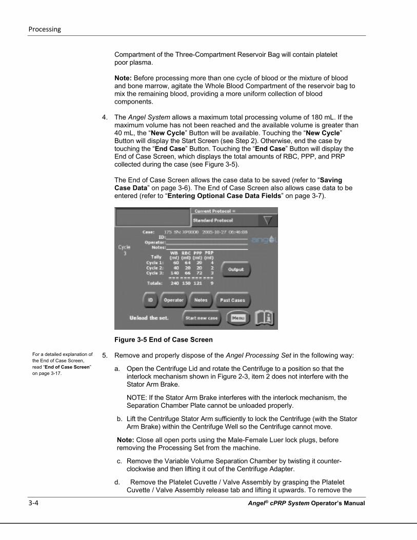
4. The Angel System allows a maximum total processing volume of 180 mL. If the
maximum volume has not been reached and the available volume is greater than 40 mL, the “New Cycle” Button will be available. Touching the “New Cycle” Button will display the Start Screen (see Step 2). Otherwise, end the case by touching the “End Case” Button. Touching the “End Case” Button will display the End of Case Screen, which displays the total amounts of RBC, PPP, and PRP collected during the case (see Figure 3-5).
The End of Case Screen allows the case data to be saved (refer to “Saving Case Data” on page 3-6). The End of Case Screen also allows case data to be entered (refer to “Entering Optional Case Data Fields” on page 3-7).
Figure 3-5 End of Case Screen
5. Remove and properly dispose of the Angel Processing Set in the following way:
a. Open the Centrifuge Lid and rotate the Centrifuge to a position so that the interlock mechanism shown in Figure 2-3, item 2 does not interfere with the Stator Arm Brake.
NOTE: If the Stator Arm Brake interferes with the interlock mechanism, the Separation Chamber Plate cannot be unloaded properly.
b. Lift the Centrifuge Stator Arm sufficiently to lock the Centrifuge (with the Stator Arm Brake) within the Centrifuge Well so the Centrifuge cannot move.
Note: Close all open ports using the Male-Female Luer lock plugs, before removing the Processing Set from the machine.
c. Remove the Variable Volume Separation Chamber by twisting it counter-clockwise and then lifting it out of the Centrifuge Adapter.
d. Remove the Platelet Cuvette / Valve Assembly by grasping the Platelet Cuvette / Valve Assembly release tab and lifting it upwards. To remove the
For a detailed explanation of the End of Case Screen, read “End of Case Screen” on page 3-17.
Processing
Angel® cPRP System Operator’s Manual 3-5
Pump Loop Tubing from the Pump Rotor, turn the Pump Rotor counter clockwise and pull the Pump Loop Tubing from it.
e. Remove the Three-Compartment Reservoir Bag from the support pins on the side of the Angel System.
6. Turn off the Angel System using the switch at the rear of the machine.
7. The Angel Processing Set is intended for single patient use only. a. Each set can be used on the same patient for up to three sequential
processing cycles. b. Once used, it should be disposed of properly.
c. Do not resterilize any part of this Processing Set.
d. The Processing Set should not be re-used for another patient.
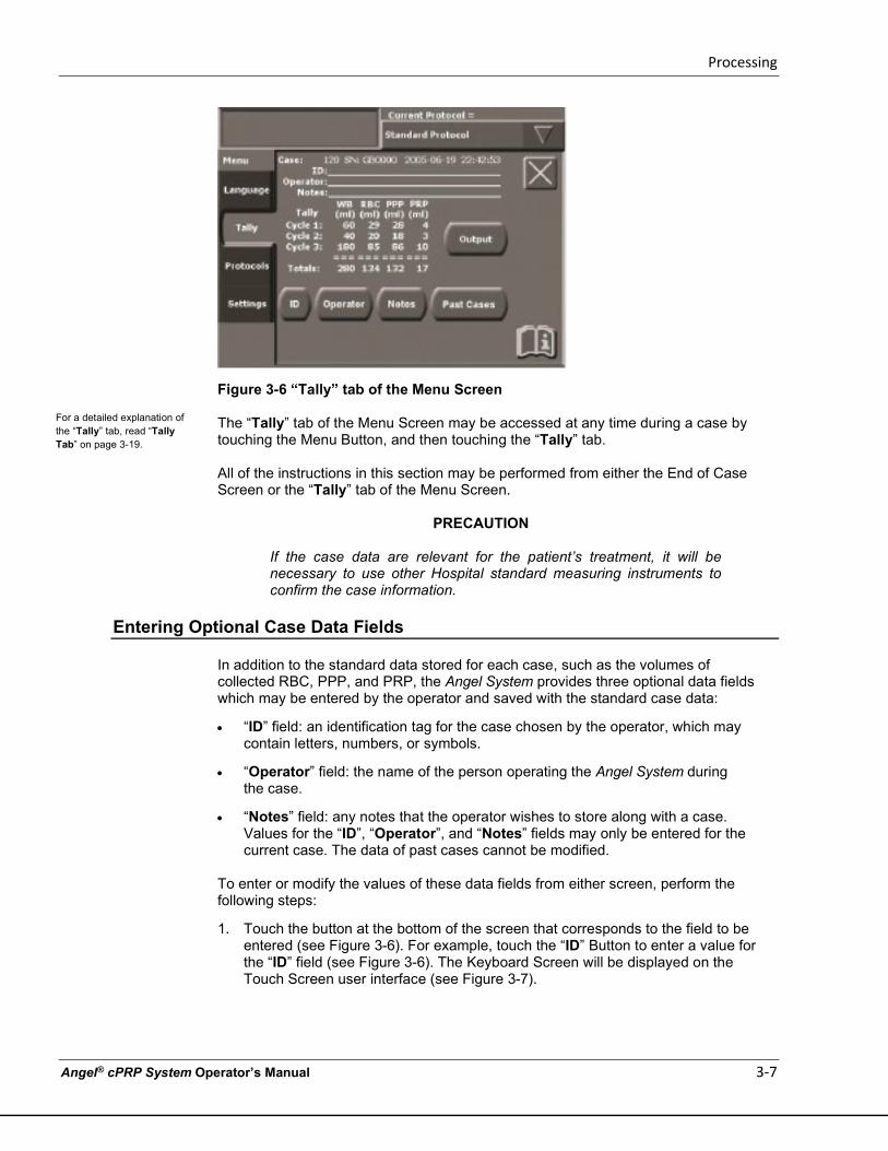
8. Affix the red Bio-Hazard Label provided in the kit (example above) to the used Angel Processing Set before disposal.
9. Biohazard waste, such as needles and contaminated surgical equipment, should be safely disposed of in accordance with the institutions policy. Disposal of used Angel Processing Sets should be performed in accordance with federal, state, and local regulations. These materials should be considered biohazardous. Universal precautions for blood-borne pathogens should be practiced (e.g., gloves, Personal Protective Equipment (PPE), etc.) when disposing of these items.
Processing
3-6 Angel® cPRP System Operator’s Manual
Saving Case Data
The Angel System stores a tally table and a detailed log file about every case that has been processed, with an option to save the tally table and the detailed case log file. The tally tables and case logs may be saved to USB storage devices. The case logs may be saved to a USB storage device. Note: Only devices or cables meeting IEC 60950 and IEC 60601-1 should be connected to the USB Port and/or Ethernet Port(if present). Failure to do so may result in operator shock. All cables used in conjunction with the device should be no longer than 1 m (3 ft.) in length. Operators connecting other devices to the USB Port must ensure compliance to the system requirements of IEC 60601-1. Every case includes the following information, which is available as an easily viewable and printable text file:
• The case number, a sequential number assigned by the machine to every case; the Angel System serial number; the date and time at which the case was started; and the Angel System software version number.
• The “ID” field, as entered by the operator (refer to “Entering Optional Case Data Fields” on page 3-7).
• The “Operator” field, as entered by the operator (refer to “Entering Optional Case Data Fields” on page 3-7).
• The tally table: the volumes (mL) of the whole blood or the blood and bone marrow mixture processed by the case, as well as volumes of RBC, PPP, and PRP collected during each cycle of the case. When available, the start and end times of the case, as well as the protocol used during processing are included.
• The “Notes” field, as entered by the operator (refer to “Entering Optional Case Data Fields” on page 3-7).
The optional fields may be left blank. The fields are displayed as blank lines.
Once the processing of a case has been completed, there are two places within the Touch Screen user interface where the case data may be saved:
• The End of Case Screen, which appears upon completion of each case (see Figure 3-5 above).
• The “Tally” tab of the Menu Screen (see Figure 3-6).
Processing
Angel® cPRP System Operator’s Manual 3-7
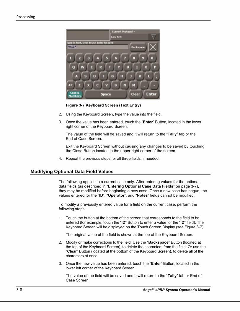
Figure 3-6 “Tally” tab of the Menu Screen
The “Tally” tab of the Menu Screen may be accessed at any time during a case by touching the Menu Button, and then touching the “Tally” tab. All of the instructions in this section may be performed from either the End of Case Screen or the “Tally” tab of the Menu Screen.
PRECAUTION
If the case data are relevant for the patient’s treatment, it will be necessary to use other Hospital standard measuring instruments to confirm the case information.
Entering Optional Case Data Fields
In addition to the standard data stored for each case, such as the volumes of collected RBC, PPP, and PRP, the Angel System provides three optional data fields which may be entered by the operator and saved with the standard case data:
• “ID” field: an identification tag for the case chosen by the operator, which may contain letters, numbers, or symbols.
• “Operator” field: the name of the person operating the Angel System during the case.
• “Notes” field: any notes that the operator wishes to store along with a case. Values for the “ID”, “Operator”, and “Notes” fields may only be entered for the current case. The data of past cases cannot be modified.
To enter or modify the values of these data fields from either screen, perform the following steps:
1. Touch the button at the bottom of the screen that corresponds to the field to be entered (see Figure 3-6). For example, touch the “ID” Button to enter a value for the “ID” field (see Figure 3-6). The Keyboard Screen will be displayed on the Touch Screen user interface (see Figure 3-7).
For a detailed explanation of the “Tally” tab, read “Tally Tab” on page 3-19.
Processing
3-8 Angel® cPRP System Operator’s Manual
Figure 3-7 Keyboard Screen (Text Entry)
2. Using the Keyboard Screen, type the value into the field.
3. Once the value has been entered, touch the “Enter” Button, located in the lower right corner of the Keyboard Screen.
The value of the field will be saved and it will return to the “Tally” tab or the End of Case Screen.
Exit the Keyboard Screen without causing any changes to be saved by touching the Close Button located in the upper right corner of the screen.
4. Repeat the previous steps for all three fields, if needed.
Modifying Optional Data Field Values
The following applies to a current case only. After entering values for the optional data fields (as described in “Entering Optional Case Data Fields” on page 3-7), they may be modified before beginning a new case. Once a new case has begun, the values entered for the “ID”, “Operator”, and “Notes” fields cannot be modified. To modify a previously entered value for a field on the current case, perform the following steps:
1. Touch the button at the bottom of the screen that corresponds to the field to be
entered (for example, touch the “ID” Button to enter a value for the “ID” field). The Keyboard Screen will be displayed on the Touch Screen Display (see Figure 3-7).
The original value of the field is shown at the top of the Keyboard Screen.
2. Modify or make corrections to the field. Use the “Backspace” Button (located at the top of the Keyboard Screen), to delete the characters from the field. Or use the “Clear” Button (located at the bottom of the Keyboard Screen), to delete all of the characters at once.
3. Once the new value has been entered, touch the “Enter” Button, located in the lower left corner of the Keyboard Screen.
The value of the field will be saved and it will return to the “Tally” tab or End of Case Screen.
Processing
Angel® cPRP System Operator’s Manual 3-9
Exit the Keyboard Screen by touching the Close Button located in the upper right corner of the screen.
4. Repeat the previous steps for all fields that require modification.
Selecting Past Cases
By default, both the End of Case Screen and the “Tally” tab of the Menu Screen only display and allow the current case to be saved. To select past cases for display or to save, perform the following steps:
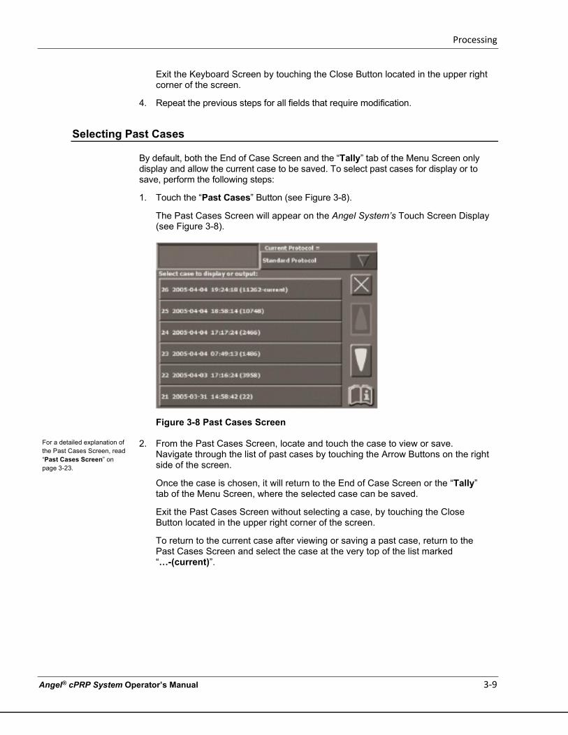
1. Touch the “Past Cases” Button (see Figure 3-8).
The Past Cases Screen will appear on the Angel System’s Touch Screen Display (see Figure 3-8).
Figure 3-8 Past Cases Screen
2. From the Past Cases Screen, locate and touch the case to view or save. Navigate through the list of past cases by touching the Arrow Buttons on the right side of the screen.
Once the case is chosen, it will return to the End of Case Screen or the “Tally” tab of the Menu Screen, where the selected case can be saved.
Exit the Past Cases Screen without selecting a case, by touching the Close Button located in the upper right corner of the screen.
To return to the current case after viewing or saving a past case, return to the Past Cases Screen and select the case at the very top of the list marked “…-(current)”.
For a detailed explanation of the Past Cases Screen, read “Past Cases Screen” on page 3-23.
Processing
3-10 Angel® cPRP System Operator’s Manual
Saving a Tally Table to a USB Storage Device
Perform the following steps to save the tally table of a case:
1. Ensure that a USB storage device is connected to the USB Port of the Angel System.
2. If the tally table of the current case will not be saved, then follow the procedure in “Selecting Past Cases” on page 3-9 to select a past case.
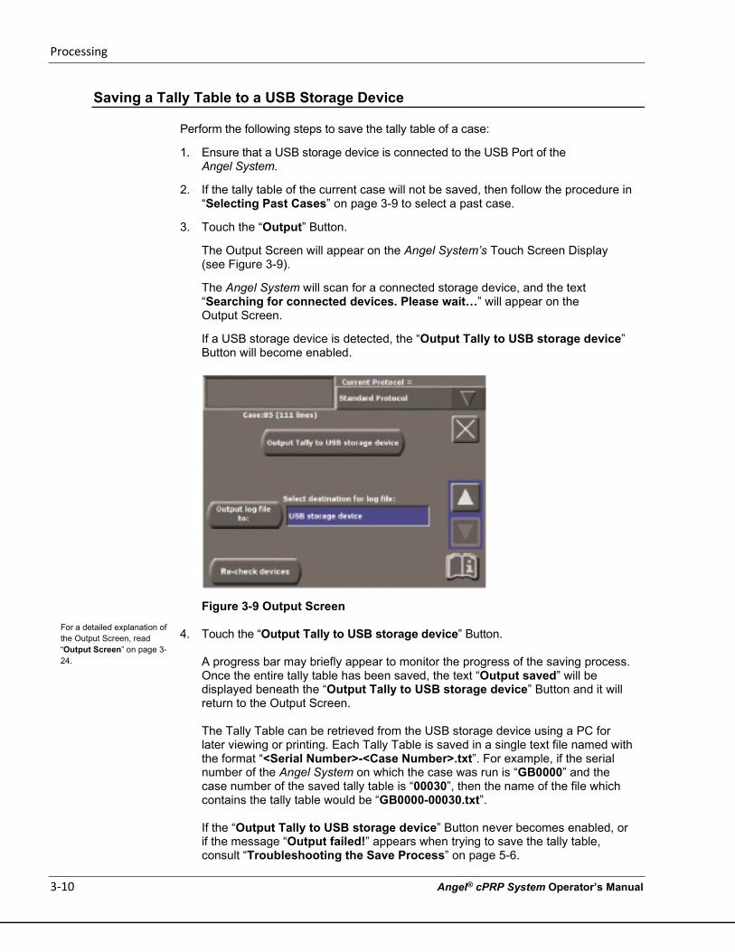
3. Touch the “Output” Button.
The Output Screen will appear on the Angel System’s Touch Screen Display (see Figure 3-9).
The Angel System will scan for a connected storage device, and the text “Searching for connected devices. Please wait…” will appear on the Output Screen.
If a USB storage device is detected, the “Output Tally to USB storage device” Button will become enabled.
Figure 3-9 Output Screen
4. Touch the “Output Tally to USB storage device” Button.
A progress bar may briefly appear to monitor the progress of the saving process. Once the entire tally table has been saved, the text “Output saved” will be displayed beneath the “Output Tally to USB storage device” Button and it will return to the Output Screen.
The Tally Table can be retrieved from the USB storage device using a PC for later viewing or printing. Each Tally Table is saved in a single text file named with the format “<Serial Number>-<Case Number>.txt”. For example, if the serial number of the Angel System on which the case was run is “GB0000” and the case number of the saved tally table is “00030”, then the name of the file which contains the tally table would be “GB0000-00030.txt”. If the “Output Tally to USB storage device” Button never becomes enabled, or if the message “Output failed!” appears when trying to save the tally table, consult “Troubleshooting the Save Process” on page 5-6.
For a detailed explanation of the Output Screen, read “Output Screen” on page 3-24.
Processing
Angel® cPRP System Operator’s Manual 3-11
You may exit the Output Screen without causing any changes to take effect by touching the Close Button located at the upper right corner of the screen.
Saving a Case Log
The data for a current or any past case may be saved to an external USB storage device.
1. Ensure that a supported USB storage device is connected to the USB Port.
Note: Only devices or cables meeting IEC 60950 and IEC 60601-1 should be connected to the USB Port and/or Ethernet Port (if present). Failure to do so may result in operator shock. All cables used in conjunction with the device should be no longer than 1 m (3 ft.) in length. Operators connecting other devices to the USB Port must ensure compliance to the system requirements of IEC 60601-1.
2. If the current case will not be saved, then select a past case to save as described in “Selecting Past Cases” on page 3-9.
3. Touch the “Output” Button.
The Output Screen will appear on the Angel System’s Touch Screen Display (see Figure 3-9).
The Angel System will then scan for a connected storage device, and the text “Searching for connected devices. Please wait…” will appear on the Output Screen.
If a USB storage device is detected, the “Output log file to:” Button will become enabled.
4. Choose the appropriate destination by performing the following:
a. Touch the “Select destination for log file:” field.
The field will become highlighted, and the Up and Down Arrow Buttons will appear on the right side of the screen.
b. Touch the Up and/or Down Arrow Buttons to scroll through available destinations which the log may be saved to.
5. Once you have chosen your desired destination, touch the “Output log file to:” Button.
A progress bar will appear to monitor the progress of the saving process. Once all data lines have been saved, the text “Output saved” will be displayed beneath the “Output log file to:” Button and it will return to the Output Screen. If the Stop Button is pressed while the case is being saved, the save process will stop, and an “Output Failed!” message will be displayed. If the “Output Tally to USB storage device” Button or the “Output log file to:” Button never becomes enabled, or if the “Output failed!” message appears when trying to save, consult the “Troubleshooting the Save Process” on page 5-6.
Exit the Output Screen by touching the Close Button located in the upper right corner of the screen. When you close this screen, it will return to the End of Case Screen or the “Tally” tab.
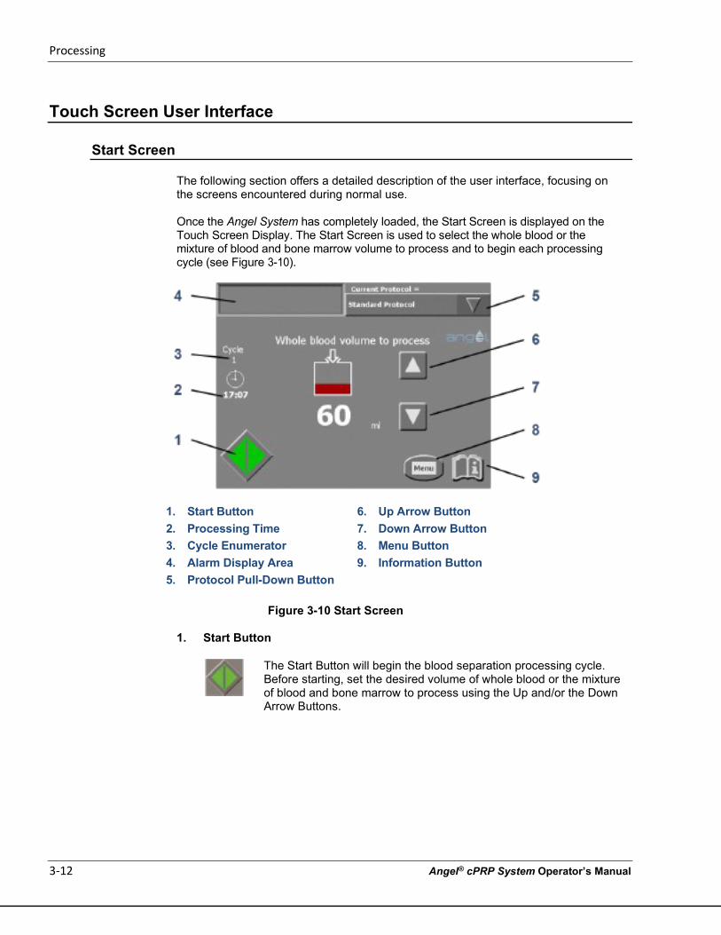
Processing
3-12 Angel® cPRP System Operator’s Manual
Touch Screen User Interface
Start Screen The following section offers a detailed description of the user interface, focusing on the screens encountered during normal use.
Once the Angel System has completely loaded, the Start Screen is displayed on the Touch Screen Display. The Start Screen is used to select the whole blood or the mixture of blood and bone marrow volume to process and to begin each processing cycle (see Figure 3-10).
1. Start Button 6. Up Arrow Button 2. Processing Time 7. Down Arrow Button 3. Cycle Enumerator 8. Menu Button 4. Alarm Display Area 9. Information Button 5. Protocol Pull-Down Button
Figure 3-10 Start Screen
1. Start Button
The Start Button will begin the blood separation processing cycle. Before starting, set the desired volume of whole blood or the mixture of blood and bone marrow to process using the Up and/or the Down Arrow Buttons.
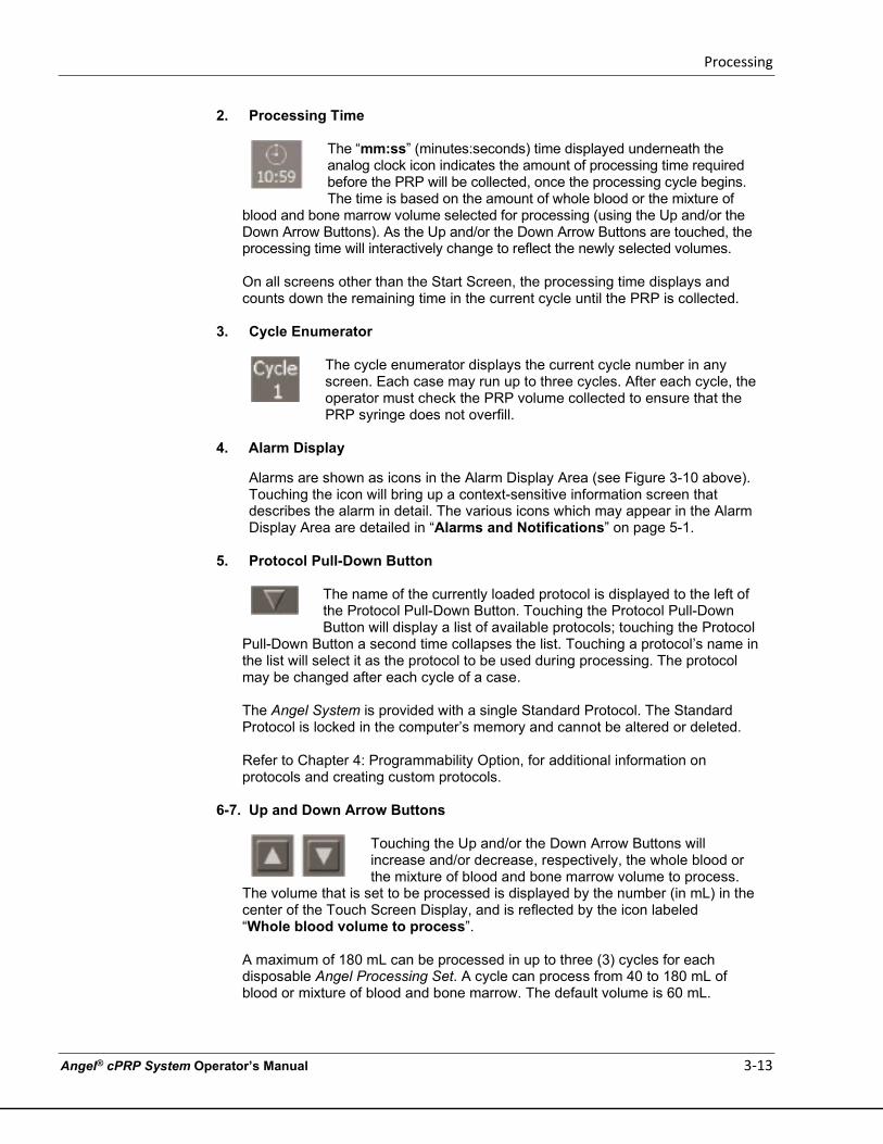
Processing
Angel® cPRP System Operator’s Manual 3-13
2. Processing Time
The “mm:ss” (minutes:seconds) time displayed underneath the analog clock icon indicates the amount of processing time required before the PRP will be collected, once the processing cycle begins. The time is based on the amount of whole blood or the mixture of
blood and bone marrow volume selected for processing (using the Up and/or the Down Arrow Buttons). As the Up and/or the Down Arrow Buttons are touched, the processing time will interactively change to reflect the newly selected volumes.
On all screens other than the Start Screen, the processing time displays and counts down the remaining time in the current cycle until the PRP is collected.
3. Cycle Enumerator
The cycle enumerator displays the current cycle number in any screen. Each case may run up to three cycles. After each cycle, the operator must check the PRP volume collected to ensure that the PRP syringe does not overfill.
4. Alarm Display
Alarms are shown as icons in the Alarm Display Area (see Figure 3-10 above). Touching the icon will bring up a context-sensitive information screen that describes the alarm in detail. The various icons which may appear in the Alarm Display Area are detailed in “Alarms and Notifications” on page 5-1.
5. Protocol Pull-Down Button
The name of the currently loaded protocol is displayed to the left of the Protocol Pull-Down Button. Touching the Protocol Pull-Down Button will display a list of available protocols; touching the Protocol
Pull-Down Button a second time collapses the list. Touching a protocol’s name in the list will select it as the protocol to be used during processing. The protocol may be changed after each cycle of a case.
The Angel System is provided with a single Standard Protocol. The Standard Protocol is locked in the computer’s memory and cannot be altered or deleted.
Refer to Chapter 4: Programmability Option, for additional information on protocols and creating custom protocols.
6-7. Up and Down Arrow Buttons
Touching the Up and/or the Down Arrow Buttons will increase and/or decrease, respectively, the whole blood or the mixture of blood and bone marrow volume to process.
The volume that is set to be processed is displayed by the number (in mL) in the center of the Touch Screen Display, and is reflected by the icon labeled “Whole blood volume to process”.
A maximum of 180 mL can be processed in up to three (3) cycles for each disposable Angel Processing Set. A cycle can process from 40 to 180 mL of blood or mixture of blood and bone marrow. The default volume is 60 mL.
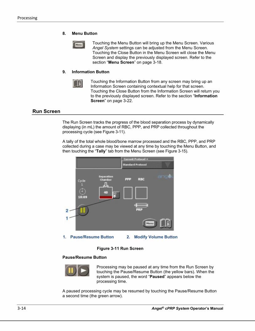
Processing
3-14 Angel® cPRP System Operator’s Manual
8. Menu Button
Touching the Menu Button will bring up the Menu Screen. Various Angel System settings can be adjusted from the Menu Screen. Touching the Close Button in the Menu Screen will close the Menu Screen and display the previously displayed screen. Refer to the section “Menu Screen” on page 3-18.
9. Information Button
Touching the Information Button from any screen may bring up an Information Screen containing contextual help for that screen. Touching the Close Button from the Information Screen will return you to the previously displayed screen. Refer to the section “Information Screen” on page 3-22.
Run Screen
The Run Screen tracks the progress of the blood separation process by dynamically displaying (in mL) the amount of RBC, PPP, and PRP collected throughout the processing cycle (see Figure 3-11).
A tally of the total whole blood/bone marrow processed and the RBC, PPP, and PRP collected during a case may be viewed at any time by touching the Menu Button, and then touching the “Tally” tab from the Menu Screen (see Figure 3-15).
1. Pause/Resume Button 2. Modify Volume Button
Figure 3-11 Run Screen
Pause/Resume Button
Processing may be paused at any time from the Run Screen by touching the Pause/Resume Button (the yellow bars). When the system is paused, the word “Paused” appears below the processing time.
A paused processing cycle may be resumed by touching the Pause/Resume Button a second time (the green arrow).
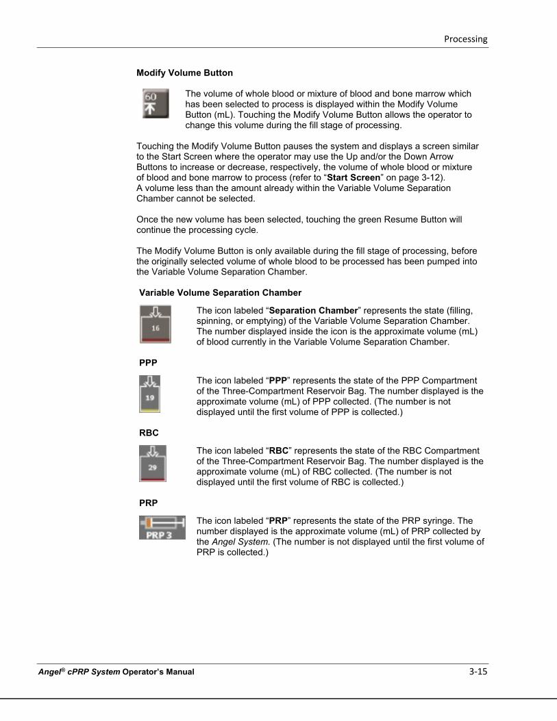
Processing
Angel® cPRP System Operator’s Manual 3-15
Modify Volume Button
The volume of whole blood or mixture of blood and bone marrow which has been selected to process is displayed within the Modify Volume Button (mL). Touching the Modify Volume Button allows the operator to change this volume during the fill stage of processing.
Touching the Modify Volume Button pauses the system and displays a screen similar to the Start Screen where the operator may use the Up and/or the Down Arrow Buttons to increase or decrease, respectively, the volume of whole blood or mixture of blood and bone marrow to process (refer to “Start Screen” on page 3-12). A volume less than the amount already within the Variable Volume Separation Chamber cannot be selected.
Once the new volume has been selected, touching the green Resume Button will continue the processing cycle.
The Modify Volume Button is only available during the fill stage of processing, before the originally selected volume of whole blood to be processed has been pumped into the Variable Volume Separation Chamber.
Variable Volume Separation Chamber
The icon labeled “Separation Chamber” represents the state (filling, spinning, or emptying) of the Variable Volume Separation Chamber. The number displayed inside the icon is the approximate volume (mL) of blood currently in the Variable Volume Separation Chamber.
PPP
The icon labeled “PPP” represents the state of the PPP Compartment of the Three-Compartment Reservoir Bag. The number displayed is the approximate volume (mL) of PPP collected. (The number is not displayed until the first volume of PPP is collected.)
RBC
The icon labeled “RBC” represents the state of the RBC Compartment of the Three-Compartment Reservoir Bag. The number displayed is the approximate volume (mL) of RBC collected. (The number is not displayed until the first volume of RBC is collected.)
PRP
The icon labeled “PRP” represents the state of the PRP syringe. The number displayed is the approximate volume (mL) of PRP collected by the Angel System. (The number is not displayed until the first volume of PRP is collected.)
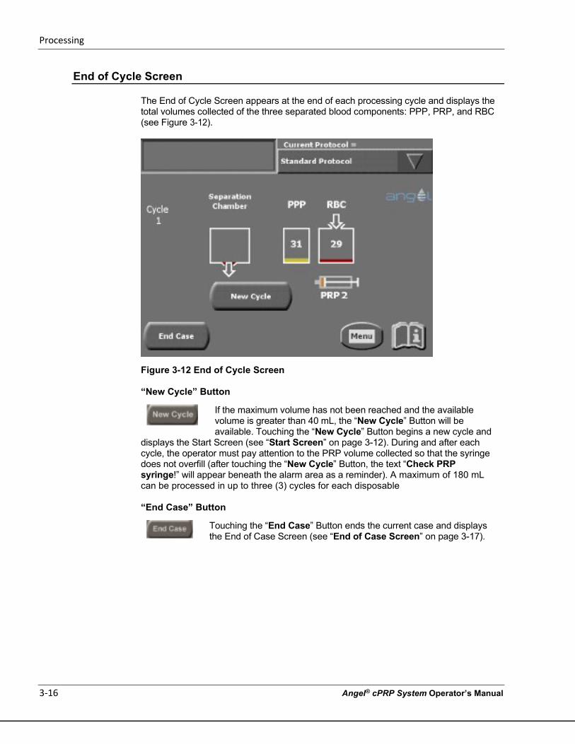
Processing
3-16 Angel® cPRP System Operator’s Manual
End of Cycle Screen
The End of Cycle Screen appears at the end of each processing cycle and displays the total volumes collected of the three separated blood components: PPP, PRP, and RBC (see Figure 3-12).
Figure 3-12 End of Cycle Screen
“New Cycle” Button
If the maximum volume has not been reached and the available volume is greater than 40 mL, the “New Cycle” Button will be available. Touching the “New Cycle” Button begins a new cycle and
displays the Start Screen (see “Start Screen” on page 3-12). During and after each cycle, the operator must pay attention to the PRP volume collected so that the syringe does not overfill (after touching the “New Cycle” Button, the text “Check PRP syringe!” will appear beneath the alarm area as a reminder). A maximum of 180 mL can be processed in up to three (3) cycles for each disposable
“End Case” Button
Touching the “End Case” Button ends the current case and displays the End of Case Screen (see “End of Case Screen” on page 3-17).
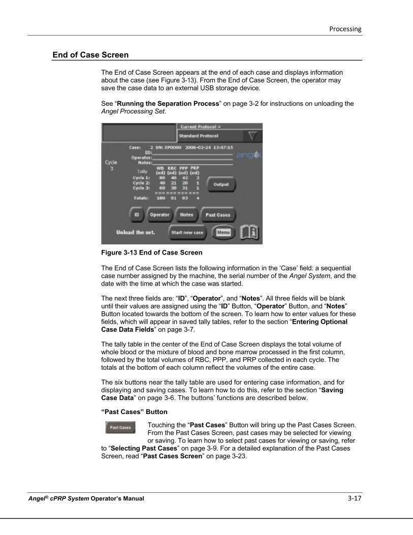
Processing
Angel® cPRP System Operator’s Manual 3-17
End of Case Screen
The End of Case Screen appears at the end of each case and displays information about the case (see Figure 3-13). From the End of Case Screen, the operator may save the case data to an external USB storage device.
See “Running the Separation Process” on page 3-2 for instructions on unloading the Angel Processing Set.
Figure 3-13 End of Case Screen
The End of Case Screen lists the following information in the ‘Case’ field: a sequential case number assigned by the machine, the serial number of the Angel System, and the date with the time at which the case was started. The next three fields are: “ID”, “Operator”, and “Notes”. All three fields will be blank until their values are assigned using the “ID” Button, “Operator” Button, and “Notes” Button located towards the bottom of the screen. To learn how to enter values for these fields, which will appear in saved tally tables, refer to the section “Entering Optional Case Data Fields” on page 3-7. The tally table in the center of the End of Case Screen displays the total volume of whole blood or the mixture of blood and bone marrow processed in the first column, followed by the total volumes of RBC, PPP, and PRP collected in each cycle. The totals at the bottom of each column reflect the volumes of the entire case. The six buttons near the tally table are used for entering case information, and for displaying and saving cases. To learn how to do this, refer to the section “Saving Case Data” on page 3-6. The buttons’ functions are described below.
“Past Cases” Button
Touching the “Past Cases” Button will bring up the Past Cases Screen. From the Past Cases Screen, past cases may be selected for viewing or saving. To learn how to select past cases for viewing or saving, refer
to “Selecting Past Cases” on page 3-9. For a detailed explanation of the Past Cases Screen, read “Past Cases Screen” on page 3-23.
Processing
3-18 Angel® cPRP System Operator’s Manual
“Output” Button
Touching the “Output” Button will bring up the Output Screen. From the Output Screen, case data may be saved to an external storage device.
To learn how to save case data, refer to “Saving Case Data” on page 3-6. For a detailed explanation of the Output Screen, read “Output Screen” on page 3-24. “ID” Button
The “ID” Button is used to enter or modify the value of the “ID” field, which is saved along with the rest of the case data. To learn how to enter the
values of a case’s optional fields, refer to “Entering Optional Case Data Fields” on page 3-7. “Operator” Button
The “Operator” Button is used to enter or modify the value of the “Operator” field, which is saved along with the rest of the case data. To
learn how to enter the values of a case’s optional fields, refer to “Entering Optional Case Data Fields” on page 3-7.
“Notes” Button
The “Notes” Button is used to enter or modify the value of the “Notes” field, which is saved along with the rest of the case data. To learn how to
enter the values of a case’s optional fields, refer to “Entering Optional Case Data Fields” on page 3-7.
“Start new case” Button
The “Start new case” Button is used to begin a new processing case. If another case will not be started, shut down the machine per the
steps in “Running the Separation Process” on page 3-2.
Menu Screen
Touching the Menu Button from any screen displays the Menu Screen which consists of a list of tabs. Touching one of the tabs on the left will display the associated menu screen.
Language Tab
The “Language” tab is used to select the language used when displaying text (see Figure 3-14).
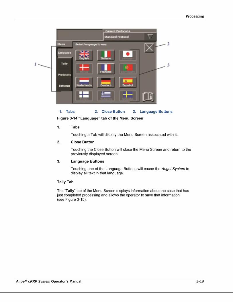
Processing
Angel® cPRP System Operator’s Manual 3-19
1. Tabs 2. Close Button 3. Language Buttons
Figure 3-14 “Language” tab of the Menu Screen
1. Tabs
Touching a Tab will display the Menu Screen associated with it.
2. Close Button
Touching the Close Button will close the Menu Screen and return to the previously displayed screen.
3. Language Buttons
Touching one of the Language Buttons will cause the Angel System to display all text in that language.
Tally Tab
The “Tally” tab of the Menu Screen displays information about the case that has just completed processing and allows the operator to save that information (see Figure 3-15).
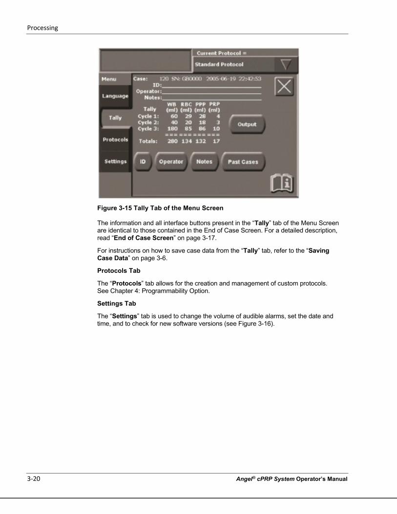
Processing
3-20 Angel® cPRP System Operator’s Manual
Figure 3-15 Tally Tab of the Menu Screen
The information and all interface buttons present in the “Tally” tab of the Menu Screen are identical to those contained in the End of Case Screen. For a detailed description, read “End of Case Screen” on page 3-17.
For instructions on how to save case data from the “Tally” tab, refer to the “Saving Case Data” on page 3-6.
Protocols Tab
The “Protocols” tab allows for the creation and management of custom protocols. See Chapter 4: Programmability Option.
Settings Tab
The “Settings” tab is used to change the volume of audible alarms, set the date and time, and to check for new software versions (see Figure 3-16).
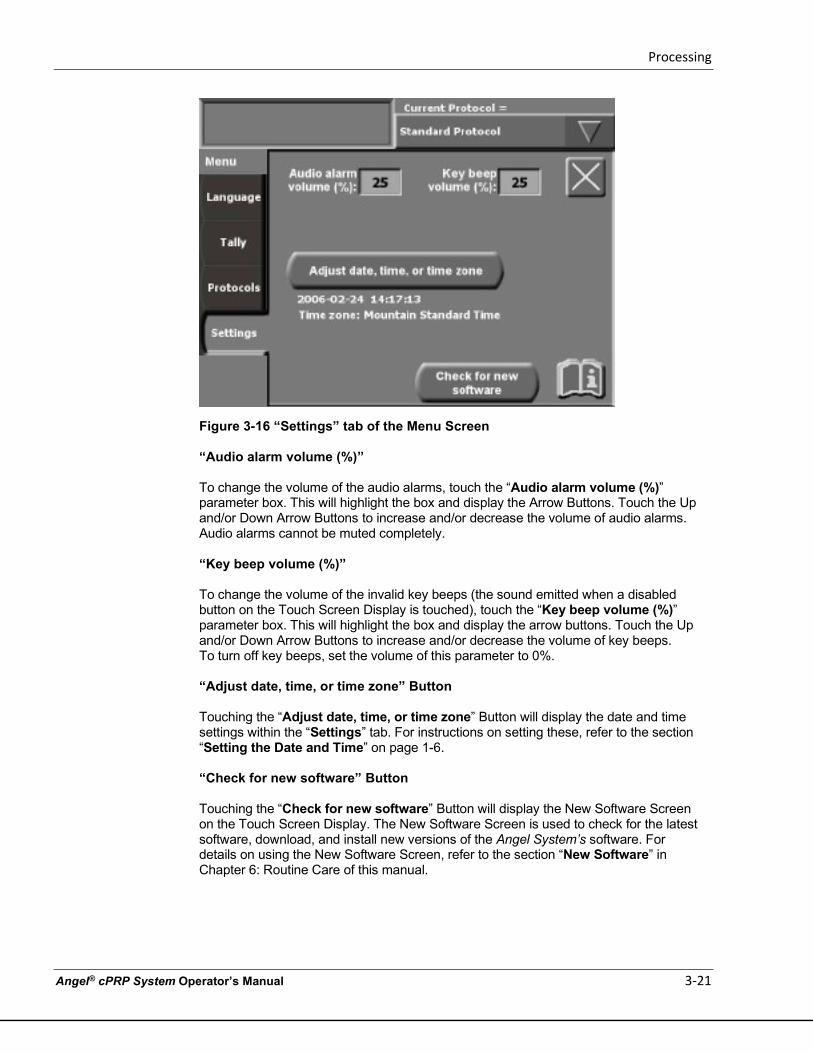
Processing
Angel® cPRP System Operator’s Manual 3-21
Figure 3-16 “Settings” tab of the Menu Screen
“Audio alarm volume (%)”
To change the volume of the audio alarms, touch the “Audio alarm volume (%)” parameter box. This will highlight the box and display the Arrow Buttons. Touch the Up and/or Down Arrow Buttons to increase and/or decrease the volume of audio alarms. Audio alarms cannot be muted completely.
“Key beep volume (%)”
To change the volume of the invalid key beeps (the sound emitted when a disabled button on the Touch Screen Display is touched), touch the “Key beep volume (%)” parameter box. This will highlight the box and display the arrow buttons. Touch the Up and/or Down Arrow Buttons to increase and/or decrease the volume of key beeps. To turn off key beeps, set the volume of this parameter to 0%.
“Adjust date, time, or time zone” Button Touching the “Adjust date, time, or time zone” Button will display the date and time settings within the “Settings” tab. For instructions on setting these, refer to the section “Setting the Date and Time” on page 1-6.
“Check for new software” Button
Touching the “Check for new software” Button will display the New Software Screen on the Touch Screen Display. The New Software Screen is used to check for the latest software, download, and install new versions of the Angel System’s software. For details on using the New Software Screen, refer to the section “New Software” in Chapter 6: Routine Care of this manual.
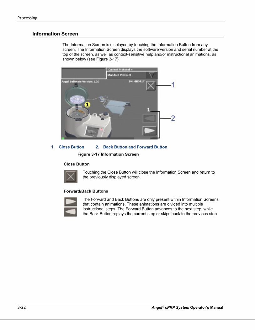
Processing
3-22 Angel® cPRP System Operator’s Manual
Information Screen
The Information Screen is displayed by touching the Information Button from any screen. The Information Screen displays the software version and serial number at the top of the screen, as well as context-sensitive help and/or instructional animations, as shown below (see Figure 3-17).
1. Close Button 2. Back Button and Forward Button
Figure 3-17 Information Screen
Close Button
Touching the Close Button will close the Information Screen and return to the previously displayed screen.
Forward/Back Buttons
The Forward and Back Buttons are only present within Information Screens that contain animations. These animations are divided into multiple instructional steps. The Forward Button advances to the next step, while the Back Button replays the current step or skips back to the previous step.
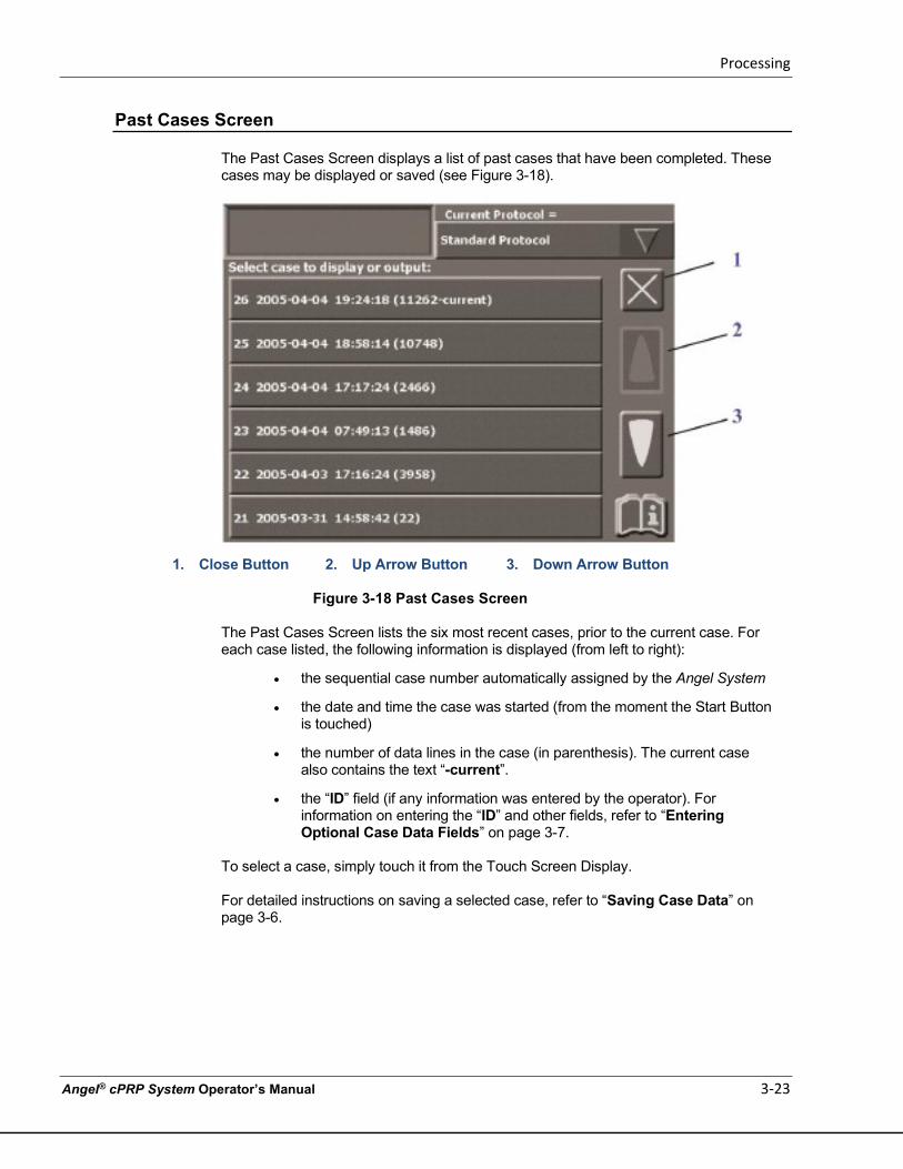
Processing
Angel® cPRP System Operator’s Manual 3-23
Past Cases Screen
The Past Cases Screen displays a list of past cases that have been completed. These cases may be displayed or saved (see Figure 3-18).
1. Close Button 2. Up Arrow Button 3. Down Arrow Button
Figure 3-18 Past Cases Screen
The Past Cases Screen lists the six most recent cases, prior to the current case. For each case listed, the following information is displayed (from left to right):
• the sequential case number automatically assigned by the Angel System
• the date and time the case was started (from the moment the Start Button is touched)
• the number of data lines in the case (in parenthesis). The current case also contains the text “-current”.
• the “ID” field (if any information was entered by the operator). For information on entering the “ID” and other fields, refer to “Entering Optional Case Data Fields” on page 3-7.
To select a case, simply touch it from the Touch Screen Display. For detailed instructions on saving a selected case, refer to “Saving Case Data” on page 3-6.
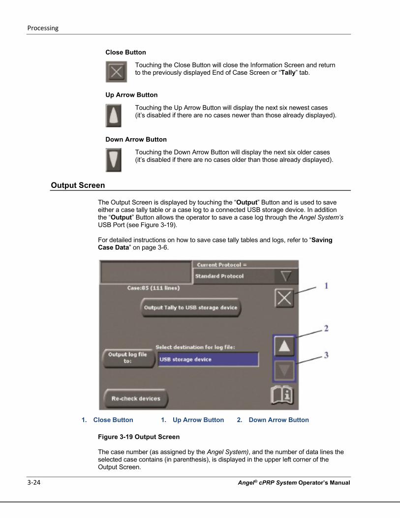
Processing
3-24 Angel® cPRP System Operator’s Manual
Close Button
Touching the Close Button will close the Information Screen and return to the previously displayed End of Case Screen or “Tally” tab.
Up Arrow Button
Touching the Up Arrow Button will display the next six newest cases (it’s disabled if there are no cases newer than those already displayed).
Down Arrow Button
Touching the Down Arrow Button will display the next six older cases (it’s disabled if there are no cases older than those already displayed).
Output Screen
The Output Screen is displayed by touching the “Output” Button and is used to save either a case tally table or a case log to a connected USB storage device. In addition the “Output” Button allows the operator to save a case log through the Angel System’s USB Port (see Figure 3-19).
For detailed instructions on how to save case tally tables and logs, refer to “Saving Case Data” on page 3-6.
1. Close Button 1. Up Arrow Button 2. Down Arrow Button
Figure 3-19 Output Screen
The case number (as assigned by the Angel System), and the number of data lines the selected case contains (in parenthesis), is displayed in the upper left corner of the Output Screen.
Processing
Angel® cPRP System Operator’s Manual 3-25
1. Close Button
Touching the Close Button will close the Output Screen and return to the previously displayed End of Case Screen or “Tally” tab without saving any data.
2-3. Up and Down Arrow Buttons
If the “Select destination for log file:” field is not highlighted, the Arrow Buttons will not be visible. If the field is highlighted, the Arrow Buttons will scroll through a list of possible destinations to
save the log file for the selected case.
“Output Tally to USB storage device” Button
Touching the “Output Tally to USB storage device” Button will start saving the tally table to a connected USB storage device.
“Output log file to:” Button
Touching the “Output log file to:” Button will start saving case data to the USB storage device.
“Select destination for log file:” Field
This field is used to select a USB storage device connected to the Angel System’s USB Port. When touched, the “Select destination for log file:” field will highlight, and the Up and Down Arrow Buttons will appear on the right side of the screen. The Arrow Buttons are used to scroll through a list of available destinations.
“Re-check devices:” Button
Touching the “Re-check devices:” Button will cause the Angel System to check for any storage device connected to the USB
Port. This feature is useful if the desired device was not found, or was not properly connected when the “Output” Button was touched.
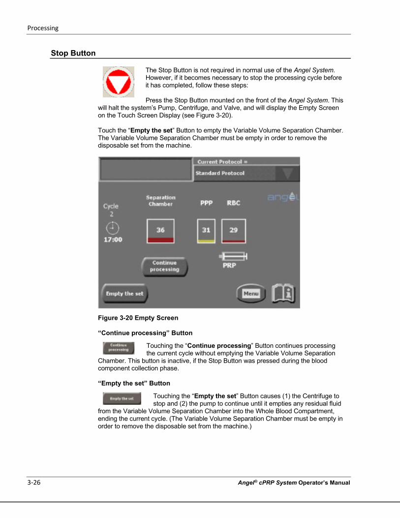
Processing
3-26 Angel® cPRP System Operator’s Manual
Stop Button
The Stop Button is not required in normal use of the Angel System. However, if it becomes necessary to stop the processing cycle before it has completed, follow these steps:
Press the Stop Button mounted on the front of the Angel System. This
will halt the system’s Pump, Centrifuge, and Valve, and will display the Empty Screen on the Touch Screen Display (see Figure 3-20).
Touch the “Empty the set” Button to empty the Variable Volume Separation Chamber. The Variable Volume Separation Chamber must be empty in order to remove the disposable set from the machine.
Figure 3-20 Empty Screen
“Continue processing” Button
Touching the “Continue processing” Button continues processing the current cycle without emptying the Variable Volume Separation
Chamber. This button is inactive, if the Stop Button was pressed during the blood component collection phase.
“Empty the set” Button
Touching the “Empty the set” Button causes (1) the Centrifuge to stop and (2) the pump to continue until it empties any residual fluid
from the Variable Volume Separation Chamber into the Whole Blood Compartment, ending the current cycle. (The Variable Volume Separation Chamber must be empty in order to remove the disposable set from the machine.)
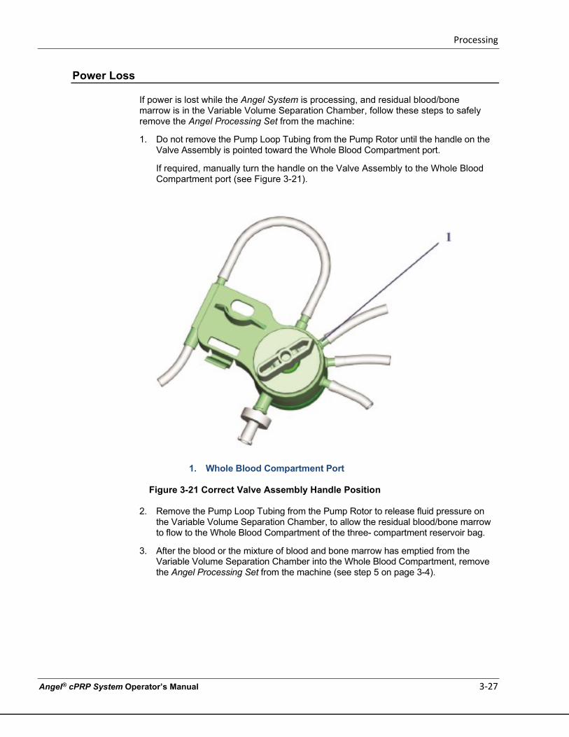
Processing
Angel® cPRP System Operator’s Manual 3-27
Power Loss
If power is lost while the Angel System is processing, and residual blood/bone marrow is in the Variable Volume Separation Chamber, follow these steps to safely remove the Angel Processing Set from the machine:
1. Do not remove the Pump Loop Tubing from the Pump Rotor until the handle on the Valve Assembly is pointed toward the Whole Blood Compartment port.
If required, manually turn the handle on the Valve Assembly to the Whole Blood Compartment port (see Figure 3-21).
1. Whole Blood Compartment Port
Figure 3-21 Correct Valve Assembly Handle Position
2. Remove the Pump Loop Tubing from the Pump Rotor to release fluid pressure on
the Variable Volume Separation Chamber, to allow the residual blood/bone marrow to flow to the Whole Blood Compartment of the three- compartment reservoir bag.
3. After the blood or the mixture of blood and bone marrow has emptied from the Variable Volume Separation Chamber into the Whole Blood Compartment, remove the Angel Processing Set from the machine (see step 5 on page 3-4).

Processing
3-28 Angel® cPRP System Operator’s Manual
This page intentionally left blank
Programmability Option
Angel® cPRP System Operator’s Manual 4-1
Chapter 4: Programmability Option
PRECAUTION
The operator of the Angel System is responsible for monitoring the system performance when using custom protocols.
Creating Custom Protocols
The Angel System is provided with a single Standard Protocol to separate the whole blood or mixture of blood and bone marrow into red cells, PPP and PRP. The parameters of the Standard Protocol have been extensively tested and optimized to produce reproducible results. By selecting the “Protocols” tab of the Menu Screen (see Figure 4-1), custom protocols may also be created that have different spin speeds and times, or that yield a PRP product containing a different proportion of red blood cells.
During blood separation using the Angel System Standard Protocol, the anticoagulated whole blood or the mixture of blood and bone marrow is pumped into the Angel System’s spinning Variable Volume Separation Chamber. The red blood cells, the heaviest elements of the blood, are separated from the lighter elements, the plasma and platelets, through centrifugation. The Angel System Standard Protocol uses a two-phase spin cycle consisting of a hard spin and a soft spin. The Standard cycle varies the RPM and Time for this two-phase spin cycle based on the volume of whole blood/bone marrow processed. On the custom Protocol screen, the Spin 1 and Spin 2 values for RPM and Time can be changed.
The first product that is collected after the two-phase cycle is complete is the PPP. The PPP is pumped from the spinning Variable Volume Separation Chamber into the PPP Compartment. When the sensor of the Angel System senses the presence of the PRP layer, the Rotating Valve changes position and directs the PRP product to the PRP syringe along with an additional volume of RBC. The additional volume of RBC maximizes the recovery of platelets. At the end of the PRP collection phase, the Rotating Valve changes its position to the RBC Compartment, and empties the remaining volume.
If the PRP volume collected (in the 20 mL Luer Lock Syringe) is diluted to a volume equal to (approximately) 10% of the processed blood/bone marrow volume, the Angel System Standard Protocol will yield a product with approximately a 7% hematocrit. The Protocol Screen allows the creation of custom protocols for increased or decreased volumes of RBC volume in the final PRP product. Since young platelets extend into the RBC layer, a change in volume of RBC in the final PRP product will also change the final concentration of platelets in the PRP product. Changes in the RPMs and Times of Spin 1 and Spin 2 may also change the concentration of platelets in the final PRP product. The change in concentration and collection of platelets when using a custom protocol is the responsibility of the Angel System operator. The operator should be knowledgeable in the methodology of blood component separation, prior to operating a custom protocol.
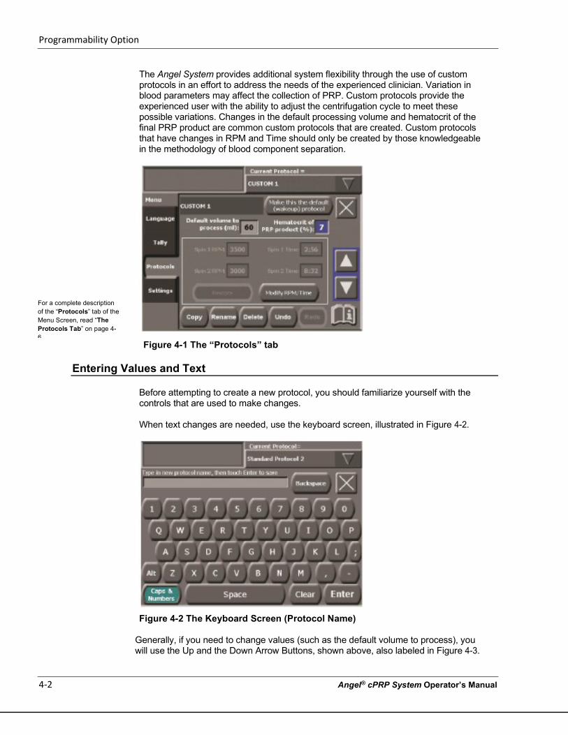
Programmability Option
4-2 Angel® cPRP System Operator’s Manual
The Angel System provides additional system flexibility through the use of custom protocols in an effort to address the needs of the experienced clinician. Variation in blood parameters may affect the collection of PRP. Custom protocols provide the experienced user with the ability to adjust the centrifugation cycle to meet these possible variations. Changes in the default processing volume and hematocrit of the final PRP product are common custom protocols that are created. Custom protocols that have changes in RPM and Time should only be created by those knowledgeable in the methodology of blood component separation.
Figure 4-1 The “Protocols” tab
Entering Values and Text
Before attempting to create a new protocol, you should familiarize yourself with the controls that are used to make changes. When text changes are needed, use the keyboard screen, illustrated in Figure 4-2.
Figure 4-2 The Keyboard Screen (Protocol Name)
Generally, if you need to change values (such as the default volume to process), you will use the Up and the Down Arrow Buttons, shown above, also labeled in Figure 4-3.
For a complete description of the “Protocols” tab of the Menu Screen, read “The Protocols Tab” on page 4-6
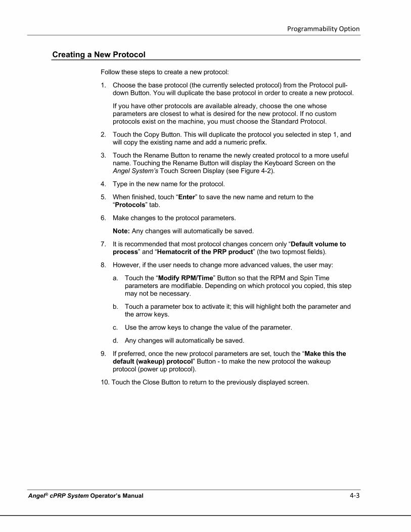
Programmability Option
Angel® cPRP System Operator’s Manual 4-3
Creating a New Protocol
Follow these steps to create a new protocol:
1. Choose the base protocol (the currently selected protocol) from the Protocol pull- down Button. You will duplicate the base protocol in order to create a new protocol.
If you have other protocols are available already, choose the one whose parameters are closest to what is desired for the new protocol. If no custom protocols exist on the machine, you must choose the Standard Protocol.
2. Touch the Copy Button. This will duplicate the protocol you selected in step 1, and will copy the existing name and add a numeric prefix.
3. Touch the Rename Button to rename the newly created protocol to a more useful name. Touching the Rename Button will display the Keyboard Screen on the Angel System’s Touch Screen Display (see Figure 4-2).
4. Type in the new name for the protocol.
5. When finished, touch “Enter” to save the new name and return to the “Protocols” tab.
6. Make changes to the protocol parameters.
Note: Any changes will automatically be saved.
7. It is recommended that most protocol changes concern only “Default volume to process” and “Hematocrit of the PRP product” (the two topmost fields).
8. However, if the user needs to change more advanced values, the user may:
a. Touch the “Modify RPM/Time” Button so that the RPM and Spin Time parameters are modifiable. Depending on which protocol you copied, this step may not be necessary.
b. Touch a parameter box to activate it; this will highlight both the parameter and the arrow keys.
c. Use the arrow keys to change the value of the parameter.
d. Any changes will automatically be saved.
9. If preferred, once the new protocol parameters are set, touch the “Make this the default (wakeup) protocol” Button - to make the new protocol the wakeup protocol (power up protocol).
10. Touch the Close Button to return to the previously displayed screen.
Programmability Option
4-4 Angel® cPRP System Operator’s Manual
Editing the Parameters of a Protocol
Follow these steps to edit the parameter values of an existing custom protocol. Note that the Standard Protocol cannot be edited.
1. Select the protocol to edit, from the Protocol Pull-Down Button.
2. Make the changes to the protocol parameters.
a. If the “Modify RPM/Time” Button is enabled, touch it so that the RPM and Spin Time parameters are modifiable. If the “Modify RPM/Time” Button is disabled, then the RPM and Spin Time parameters can already be edited.
b. Touch a parameter box to activate it; this will highlight both the parameter and the arrow keys.
c. Use the arrow keys to change the value of the parameter.
d. Any changes will automatically be saved.
3. Touch the Close Button to return to the previously displayed screen.
Restoring the Parameters of a Protocol
The values of the RPM and Spin Time parameters for any custom protocol may be restored to the recommended Standard Protocol algorithm settings at any time. These are the values used for the Standard Protocol, and are determined by the selected volume of whole blood or the blood mixed with bone marrow to process. As the volume is changed, the RPM and Spin Time parameters are changed to optimize platelet collection.
To restore the parameters of a protocol, follow these steps:
1. From the Protocol Pull-Down Button, select the protocol you wish to restore.
2. Touch the “Restore” Button.
3. Touch the Close Button to return to the previously displayed screen.
Programmability Option
Angel® cPRP System Operator’s Manual 4-5
Renaming a Protocol
Follow these steps to rename an existing custom protocol. Note that the Standard Protocol cannot be renamed.
1. Select the protocol you wish to rename, from the Protocol Pull-Down Button.
2. Touch the Rename Button. Touching the Rename Button will display the Keyboard Screen on the Angel System’s Touch Screen Display (see Figure 4-2).
3. Use the “Backspace” Button to edit the previous name, or clear the previous name by touching the “Clear” Button, located at the bottom of the Keyboard Screen. Then type in the new name for the protocol.
You may exit the Keyboard Screen without causing any changes to take effect at any time by touching the Close Button located at the upper right corner of the screen.
4. When finished, touch “Enter” to save the new name and return to the “Protocols” tab.
5. Touch the Close Button to return to the previously displayed screen.
Changing the Wakeup Protocol
Follow these steps to set a protocol as the wakeup protocol (selected at power-up). The wakeup protocol will be the selected protocol by default whenever the Angel System is turned on.
1. Select the protocol you wish to set as the wakeup protocol, from the Protocol Pull-Down Button.
2. Touch the “Make this the default (wakeup) protocol” Button.
3. Touch the Close Button to save the protocol and return to the previously displayed screen.
Deleting a Protocol
Follow these steps to delete an existing custom protocol. Note that the Standard Protocol cannot be deleted.
1. Select the protocol you wish to delete, from the Protocol Pull-Down Button.
2. Touch the Delete Button. The protocol will be deleted and will no longer be available from the Protocol Pull-Down Button.
3. Touch the Close Button to return to the previously displayed screen.
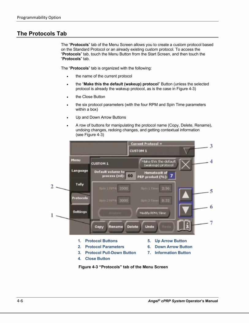
Programmability Option
4-6 Angel® cPRP System Operator’s Manual
The Protocols Tab
The “Protocols” tab of the Menu Screen allows you to create a custom protocol based on the Standard Protocol or an already existing custom protocol. To access the “Protocols” tab, touch the Menu Button from the Start Screen, and then touch the “Protocols” tab. The “Protocols” tab is organized with the following:
• the name of the current protocol
• the “Make this the default (wakeup) protocol” Button (unless the selected protocol is already the wakeup protocol, as is the case in Figure 4-3)
• the Close Button
• the six protocol parameters (with the four RPM and Spin Time parameters within a box)
• Up and Down Arrow Buttons
• A row of buttons for manipulating the protocol name (Copy, Delete, Rename), undoing changes, redoing changes, and getting contextual information (see Figure 4-3)
1. Protocol Buttons 5. Up Arrow Button 2. Protocol Parameters 6. Down Arrow Button 3. Protocol Pull-Down Button 7. Information Button 4. Close Button
Figure 4-3 “Protocols” tab of the Menu Screen
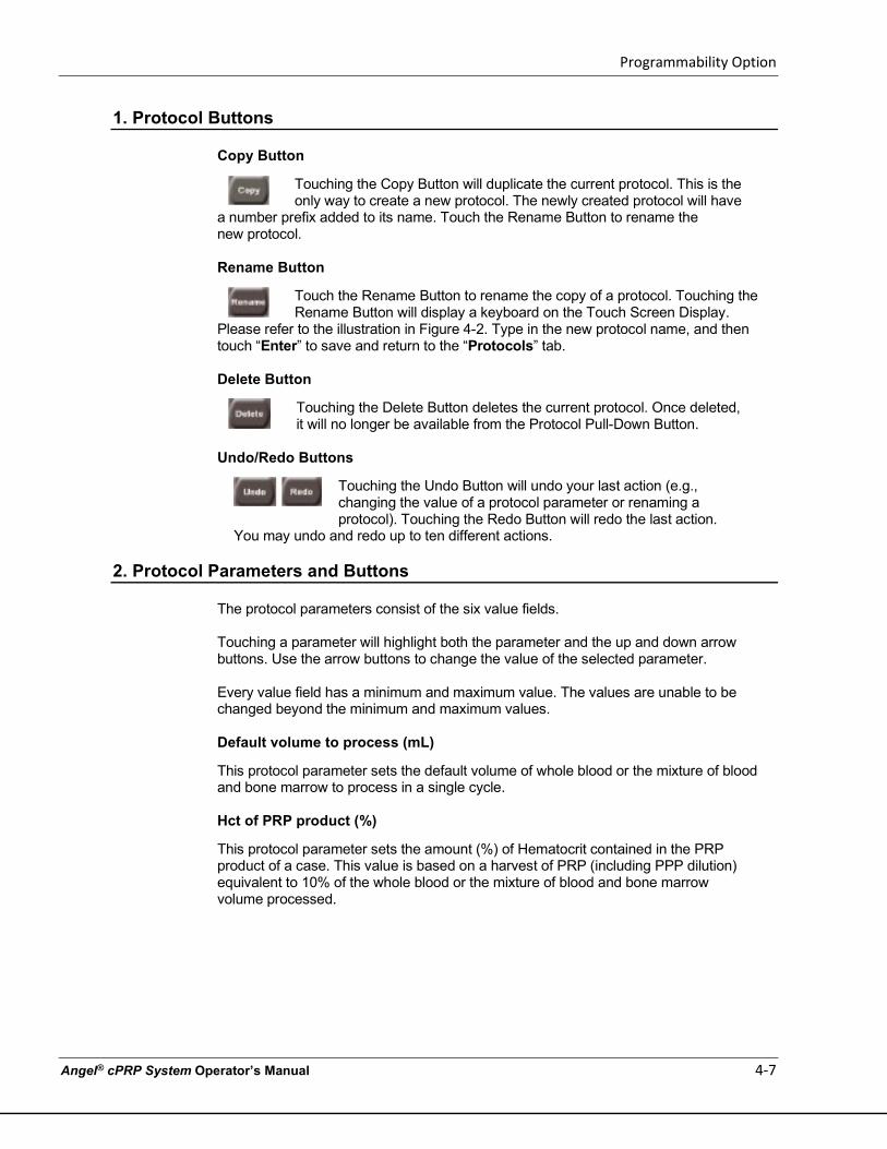
Programmability Option
Angel® cPRP System Operator’s Manual 4-7
1. Protocol Buttons
Copy Button
Touching the Copy Button will duplicate the current protocol. This is the only way to create a new protocol. The newly created protocol will have
a number prefix added to its name. Touch the Rename Button to rename the new protocol. Rename Button
Touch the Rename Button to rename the copy of a protocol. Touching the Rename Button will display a keyboard on the Touch Screen Display.
Please refer to the illustration in Figure 4-2. Type in the new protocol name, and then touch “Enter” to save and return to the “Protocols” tab. Delete Button
Touching the Delete Button deletes the current protocol. Once deleted, it will no longer be available from the Protocol Pull-Down Button.
Undo/Redo Buttons
Touching the Undo Button will undo your last action (e.g., changing the value of a protocol parameter or renaming a protocol). Touching the Redo Button will redo the last action.
You may undo and redo up to ten different actions.
2. Protocol Parameters and Buttons
The protocol parameters consist of the six value fields. Touching a parameter will highlight both the parameter and the up and down arrow buttons. Use the arrow buttons to change the value of the selected parameter. Every value field has a minimum and maximum value. The values are unable to be changed beyond the minimum and maximum values. Default volume to process (mL)
This protocol parameter sets the default volume of whole blood or the mixture of blood and bone marrow to process in a single cycle. Hct of PRP product (%)
This protocol parameter sets the amount (%) of Hematocrit contained in the PRP product of a case. This value is based on a harvest of PRP (including PPP dilution) equivalent to 10% of the whole blood or the mixture of blood and bone marrow volume processed.
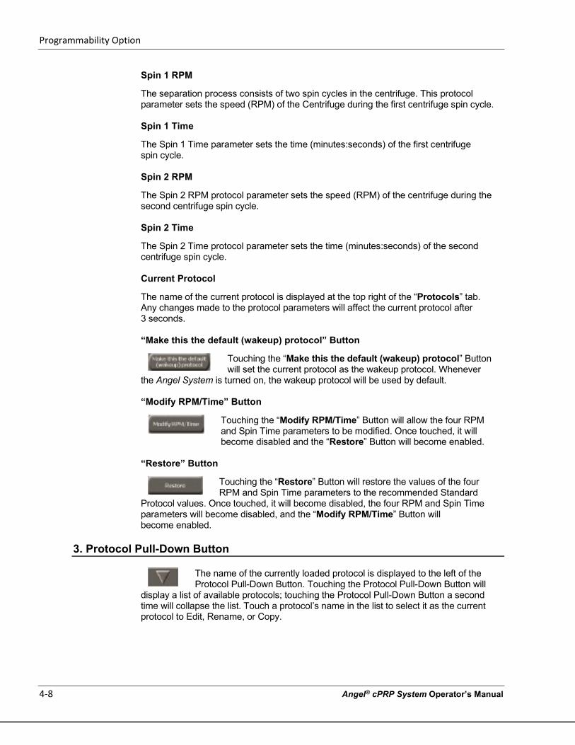
Programmability Option
4-8 Angel® cPRP System Operator’s Manual
Spin 1 RPM
The separation process consists of two spin cycles in the centrifuge. This protocol parameter sets the speed (RPM) of the Centrifuge during the first centrifuge spin cycle.
Spin 1 Time
The Spin 1 Time parameter sets the time (minutes:seconds) of the first centrifuge spin cycle.
Spin 2 RPM
The Spin 2 RPM protocol parameter sets the speed (RPM) of the centrifuge during the second centrifuge spin cycle.
Spin 2 Time
The Spin 2 Time protocol parameter sets the time (minutes:seconds) of the second centrifuge spin cycle.
Current Protocol
The name of the current protocol is displayed at the top right of the “Protocols” tab. Any changes made to the protocol parameters will affect the current protocol after 3 seconds.
“Make this the default (wakeup) protocol” Button
Touching the “Make this the default (wakeup) protocol” Button will set the current protocol as the wakeup protocol. Whenever
the Angel System is turned on, the wakeup protocol will be used by default.
“Modify RPM/Time” Button
Touching the “Modify RPM/Time” Button will allow the four RPM and Spin Time parameters to be modified. Once touched, it will become disabled and the “Restore” Button will become enabled.
“Restore” Button
Touching the “Restore” Button will restore the values of the four RPM and Spin Time parameters to the recommended Standard
Protocol values. Once touched, it will become disabled, the four RPM and Spin Time parameters will become disabled, and the “Modify RPM/Time” Button will become enabled.
3. Protocol Pull-Down Button
The name of the currently loaded protocol is displayed to the left of the Protocol Pull-Down Button. Touching the Protocol Pull-Down Button will
display a list of available protocols; touching the Protocol Pull-Down Button a second time will collapse the list. Touch a protocol’s name in the list to select it as the current protocol to Edit, Rename, or Copy.
Programmability Option
Angel® cPRP System Operator’s Manual 4-9
4. Close Button
Touching the Close Button will exit the Menu Screen, returning to the previously displayed screen.
5-6. Up and Down Arrow Buttons
Touch the Up and/or Down Arrow Buttons to increase and/or decrease, respectively, the value of the currently selected protocol parameter. Changes are saved automatically.
7. Information Button
Touching the Information Button will bring up an Information Screen containing contextual help. Touching the Close Button from the Information Screen will return you to displayed screen.

Programmability Option
4-10 Angel® cPRP System Operator’s Manual
This page intentionally left blank
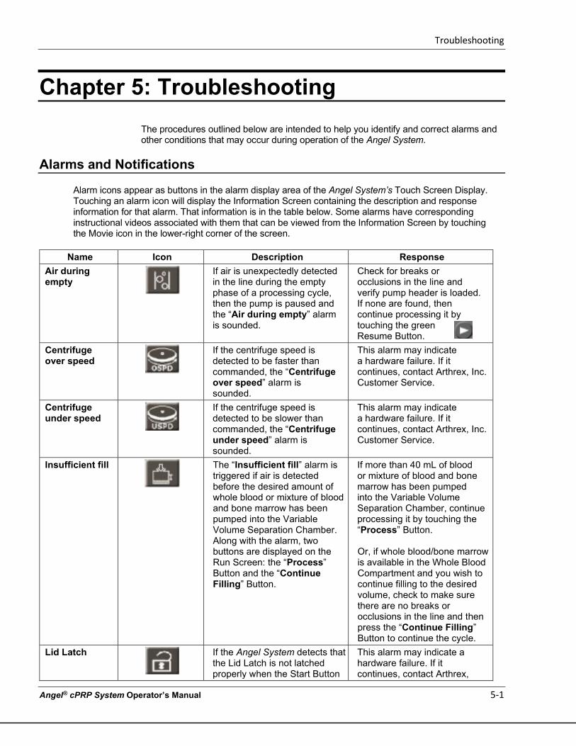
Troubleshooting
Angel® cPRP System Operator’s Manual 5-1
Chapter 5: Troubleshooting The procedures outlined below are intended to help you identify and correct alarms and other conditions that may occur during operation of the Angel System.
Alarms and Notifications
Alarm icons appear as buttons in the alarm display area of the Angel System’s Touch Screen Display. Touching an alarm icon will display the Information Screen containing the description and response information for that alarm. That information is in the table below. Some alarms have corresponding instructional videos associated with them that can be viewed from the Information Screen by touching the Movie icon in the lower-right corner of the screen.
Name Icon Description Response Air during empty
If air is unexpectedly detected in the line during the empty phase of a processing cycle, then the pump is paused and the “Air during empty” alarm is sounded.
Check for breaks or occlusions in the line and verify pump header is loaded. If none are found, then continue processing it by touching the green Resume Button.
Centrifuge over speed
If the centrifuge speed is detected to be faster than commanded, the “Centrifuge over speed” alarm is sounded.
This alarm may indicate a hardware failure. If it continues, contact Arthrex, Inc. Customer Service.
Centrifuge under speed
If the centrifuge speed is detected to be slower than commanded, the “Centrifuge under speed” alarm is sounded.
This alarm may indicate a hardware failure. If it continues, contact Arthrex, Inc. Customer Service.
Insufficient fill
The “Insufficient fill” alarm is triggered if air is detected before the desired amount of whole blood or mixture of blood and bone marrow has been pumped into the Variable Volume Separation Chamber. Along with the alarm, two buttons are displayed on the Run Screen: the “Process” Button and the “Continue Filling” Button.
If more than 40 mL of blood or mixture of blood and bone marrow has been pumped into the Variable Volume Separation Chamber, continue processing it by touching the “Process” Button.
Or, if whole blood/bone marrow is available in the Whole Blood Compartment and you wish to continue filling to the desired volume, check to make sure there are no breaks or occlusions in the line and then press the “Continue Filling” Button to continue the cycle.
Lid Latch
If the Angel System detects that the Lid Latch is not latched properly when the Start Button
This alarm may indicate a hardware failure. If it continues, contact Arthrex,
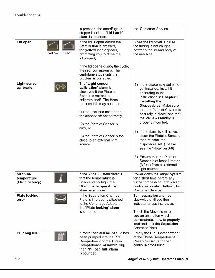
Troubleshooting
5-2 Angel® cPRP System Operator’s Manual
is pressed, the centrifuge is stopped and the “Lid Latch” alarm is sounded.
Inc. Customer Service.
Lid open
yellow red
If the lid is open before the Start Button is pressed, the yellow icon appears, prompting you to close the lid properly.
If the lid opens during the cycle, the red icon appears. The centrifuge stops until the problem is corrected.
Close the lid cover. Ensure the tubing is not caught between the lid and body of the machine.
Light sensor calibration
The “Light sensor calibration” alarm is displayed if the Platelet Sensor is not able to calibrate itself. The three reasons this may occur are: (1) the user has not loaded the disposable set correctly, (2) the Platelet Sensor is dirty, or (3) the Platelet Sensor is too close to an external light source.
(1) If the disposable set is not yet installed, install it according to the instructions in Chapter 2: Installing the Disposables. Make sure that the Platelet Cuvette is securely in place, and that the Valve Assembly is properly mounted.
(2) If the alarm is still active,
clean the Platelet Sensor, then reinstall the disposable set. (Please see the “Note” on 6-8)
(3) Ensure that the Platelet
Sensor is at least 1 meter (3 feet) from all external light sources.
Machine temperature (Machine temp)
If the Angel System detects that the temperature is unacceptably high, the “Machine temperature” alarm is sounded.
Power down the Angel System for a short time before any further processing. If this alarm continues, contact Arthrex, Inc. Customer Service.
Plate locking error
If the Separation Chamber Plate is improperly attached to the Centrifuge Adapter, the “Plate locking” alarm is sounded.
Turn separation chamber clockwise until position indicator snaps into place.
Touch the Movie icon to see an animation which demonstrates how to properly load and lock the Separation Chamber Plate.
PPP bag full
If more than 300 mL of fluid has been pumped into the PPP Compartment of the Three-Compartment Reservoir Bag, the “PPP bag full” alarm is sounded.
Empty the PPP Compartment of the Three-Compartment Reservoir Bag, and then continue processing.
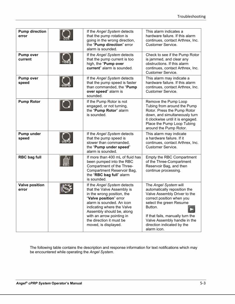
Troubleshooting
Angel® cPRP System Operator’s Manual 5-3
The following table contains the description and response information for text notifications which may be encountered while operating the Angel System.
Pump direction error
If the Angel System detects that the pump rotation is going in the wrong direction, the “Pump direction” error alarm is sounded.
This alarm indicates a hardware failure. If this alarm continues, contact Arthrex, Inc. Customer Service.
Pump over current
If the Angel System detects that the pump current is too high, the “Pump over current” alarm is sounded.
Check to see if the Pump Rotor is jammed, and clear any obstructions. If this alarm continues, contact Arthrex, Inc. Customer Service.
Pump over speed
If the Angel System detects that the pump speed is faster than commanded, the “Pump over speed” alarm is sounded.
This alarm may indicate a hardware failure. If this alarm continues, contact Arthrex, Inc. Customer Service.
Pump Rotor
If the Pump Rotor is not engaged, or not turning, the “Pump Rotor” alarm is sounded.
Remove the Pump Loop Tubing from around the Pump Rotor. Press the Pump Rotor down, and simultaneously turn it clockwise until it is engaged. Place the Pump Loop Tubing around the Pump Rotor.
Pump under speed
If the Angel System detects that the pump speed is slower than commanded, the “Pump under speed” alarm is sounded.
This alarm may indicate a hardware failure. If it continues, contact Arthrex, Inc. Customer Service.
RBC bag full
If more than 400 mL of fluid has been pumped into the RBC Compartment of the Three-Compartment Reservoir Bag, the “RBC bag full” alarm is sounded.
Empty the RBC Compartment of the Three-Compartment Reservoir Bag, and then continue processing.
Valve position error
If the Angel System detects that the Valve Assembly is in the wrong position, the “Valve position” error alarm is sounded. An icon indicating where the Valve Assembly should be, along with an arrow pointing in the direction it must be moved, is displayed.
The Angel System will automatically reposition the Valve Assembly Driver to the correct position when you select the green Resume Button.
If that fails, manually turn the Valve Assembly handle in the direction indicated by the alarm icon.
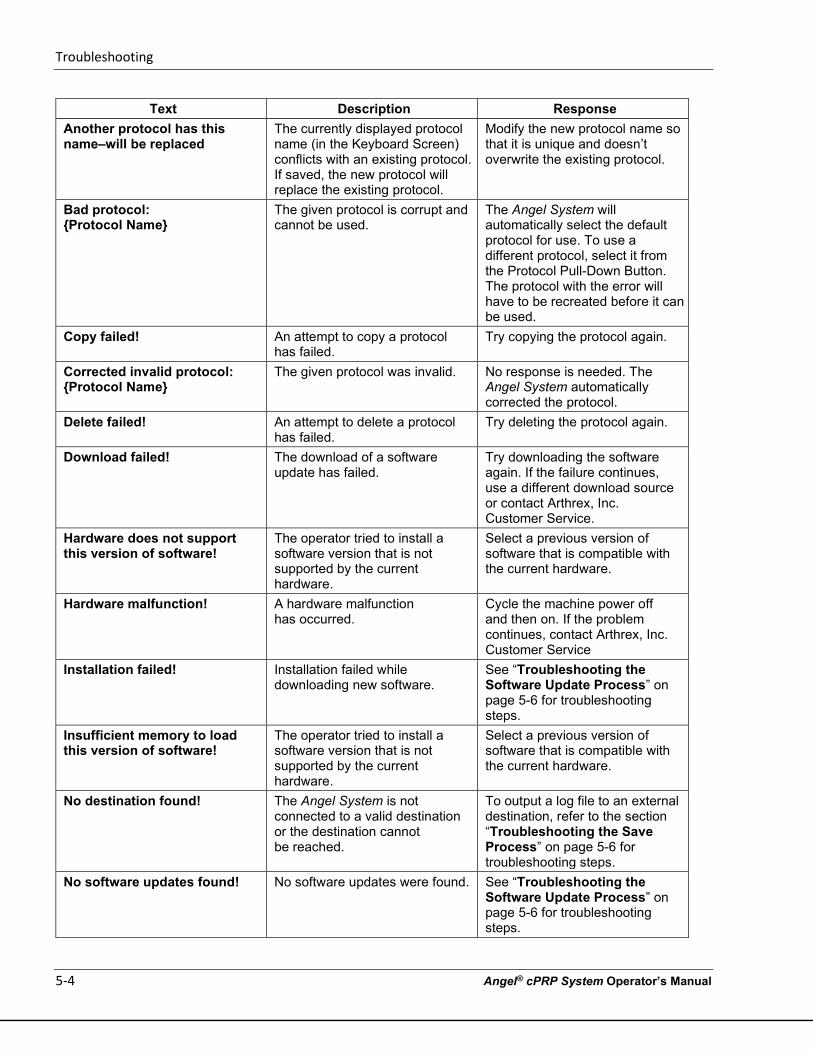
Troubleshooting
5-4 Angel® cPRP System Operator’s Manual
Text Description Response Another protocol has this name–will be replaced
The currently displayed protocol name (in the Keyboard Screen) conflicts with an existing protocol. If saved, the new protocol will replace the existing protocol.
Modify the new protocol name so that it is unique and doesn’t overwrite the existing protocol.
Bad protocol: {Protocol Name}
The given protocol is corrupt and cannot be used.
The Angel System will automatically select the default protocol for use. To use a different protocol, select it from the Protocol Pull-Down Button. The protocol with the error will have to be recreated before it can be used.
Copy failed! An attempt to copy a protocol has failed.
Try copying the protocol again.
Corrected invalid protocol: {Protocol Name}
The given protocol was invalid. No response is needed. The Angel System automatically corrected the protocol.
Delete failed! An attempt to delete a protocol has failed.
Try deleting the protocol again.
Download failed! The download of a software update has failed.
Try downloading the software again. If the failure continues, use a different download source or contact Arthrex, Inc. Customer Service.
Hardware does not support this version of software!
The operator tried to install a software version that is not supported by the current hardware.
Select a previous version of software that is compatible with the current hardware.
Hardware malfunction! A hardware malfunction has occurred.
Cycle the machine power off and then on. If the problem continues, contact Arthrex, Inc. Customer Service
Installation failed! Installation failed while downloading new software.
See “Troubleshooting the Software Update Process” on page 5-6 for troubleshooting steps.
Insufficient memory to load this version of software!
The operator tried to install a software version that is not supported by the current hardware.
Select a previous version of software that is compatible with the current hardware.
No destination found! The Angel System is not connected to a valid destination or the destination cannot be reached.
To output a log file to an external destination, refer to the section “Troubleshooting the Save Process” on page 5-6 for troubleshooting steps.
No software updates found! No software updates were found. See “Troubleshooting the Software Update Process” on page 5-6 for troubleshooting steps.
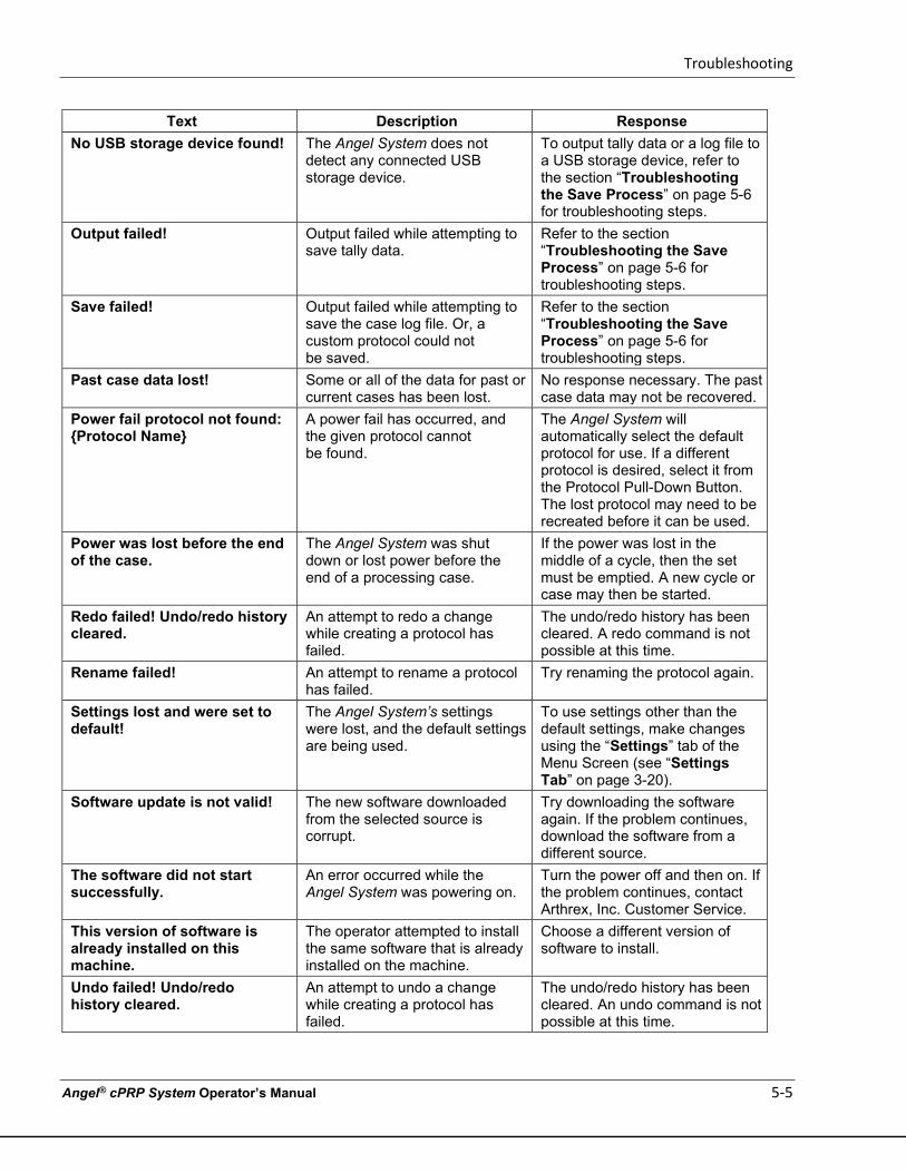
Troubleshooting
Angel® cPRP System Operator’s Manual 5-5
Text Description Response No USB storage device found! The Angel System does not
detect any connected USB storage device.
To output tally data or a log file to a USB storage device, refer to the section “Troubleshooting the Save Process” on page 5-6 for troubleshooting steps.
Output failed! Output failed while attempting to save tally data.
Refer to the section “Troubleshooting the Save Process” on page 5-6 for troubleshooting steps.
Save failed! Output failed while attempting to save the case log file. Or, a custom protocol could not be saved.
Refer to the section “Troubleshooting the Save Process” on page 5-6 for troubleshooting steps.
Past case data lost! Some or all of the data for past or current cases has been lost.
No response necessary. The past case data may not be recovered.
Power fail protocol not found: {Protocol Name}
A power fail has occurred, and the given protocol cannot be found.
The Angel System will automatically select the default protocol for use. If a different protocol is desired, select it from the Protocol Pull-Down Button. The lost protocol may need to be recreated before it can be used.
Power was lost before the end of the case.
The Angel System was shut down or lost power before the end of a processing case.
If the power was lost in the middle of a cycle, then the set must be emptied. A new cycle or case may then be started.
Redo failed! Undo/redo history cleared.
An attempt to redo a change while creating a protocol has failed.
The undo/redo history has been cleared. A redo command is not possible at this time.
Rename failed! An attempt to rename a protocol has failed.
Try renaming the protocol again.
Settings lost and were set to default!
The Angel System’s settings were lost, and the default settings are being used.
To use settings other than the default settings, make changes using the “Settings” tab of the Menu Screen (see “Settings Tab” on page 3-20).
Software update is not valid! The new software downloaded from the selected source is corrupt.
Try downloading the software again. If the problem continues, download the software from a different source.
The software did not start successfully.
An error occurred while the Angel System was powering on.
Turn the power off and then on. If the problem continues, contact Arthrex, Inc. Customer Service.
This version of software is already installed on this machine.
The operator attempted to install the same software that is already installed on the machine.
Choose a different version of software to install.
Undo failed! Undo/redo history cleared.
An attempt to undo a change while creating a protocol has failed.
The undo/redo history has been cleared. An undo command is not possible at this time.
Troubleshooting
5-6 Angel® cPRP System Operator’s Manual
Text Description Response Wakeup protocol not found: {Protocol Name}
The wakeup protocol cannot be found.
The Angel System will automatically select the default protocol as the wakeup protocol. If a different protocol is desired, select it from the Protocol pull- down Button, and then set it as the wakeup protocol from the “Protocols” tab of the Menu Screen.
Troubleshooting the Save Process
If you receive the error messages “No destination found!”, “No USB storage device found!”, “Output failed!”, “Save failed!”, or encounter other difficulties while attempting to save the case data, try the following:
• Ensure the USB storage device or cable is properly connected to the port on the left side of the machine. If you are having difficulties locating the port, see “Angel System Components” on page 1-2.
• Once you have fixed any connection problems, touch the “Re-check devices” Button from the Output Screen. The Angel System should now be able to find the appropriate device, and the saving process should be successful.
• If an Output Screen becomes unresponsive, cycle the machine power off and then on to correct the error condition.
If you continue to experience difficulty, contact Arthrex, Inc. Customer Service.
Troubleshooting the Software Update Process
If you receive the error messages, “Installation failed!” “No software updates found!” or encounter other difficulties while attempting to install the new system software from the New Software Screen, try the following:
• Ensure the USB storage device or cable is properly connected to the port on the left side of the machine. If you are having difficulties locating the port, see “Angel System Components” on page 1-2.
• If you are attempting to update the software from a USB storage device, ensure that the device has a valid version of the Angel System software on it.
• Once you have fixed any connection problems, touch the “Re-check sources” Button from the New Software Screen. The Angel System should now be able to find the valid software versions from the desired source.
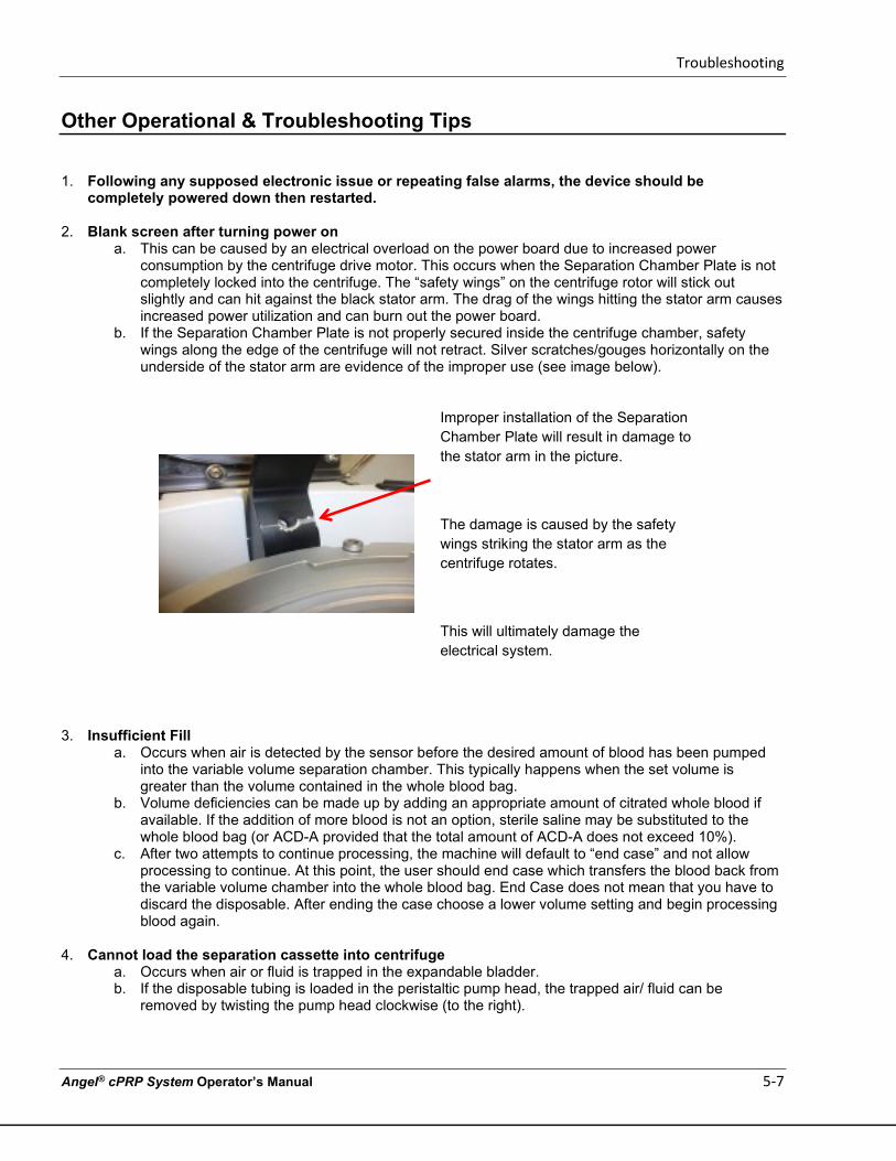
Troubleshooting
Angel® cPRP System Operator’s Manual 5-7
Other Operational & Troubleshooting Tips
1. Following any supposed electronic issue or repeating false alarms, the device should be completely powered down then restarted.
2. Blank screen after turning power on
a. This can be caused by an electrical overload on the power board due to increased power consumption by the centrifuge drive motor. This occurs when the Separation Chamber Plate is not completely locked into the centrifuge. The “safety wings” on the centrifuge rotor will stick out slightly and can hit against the black stator arm. The drag of the wings hitting the stator arm causes increased power utilization and can burn out the power board.
b. If the Separation Chamber Plate is not properly secured inside the centrifuge chamber, safety wings along the edge of the centrifuge will not retract. Silver scratches/gouges horizontally on the underside of the stator arm are evidence of the improper use (see image below).
Improper installation of the Separation Chamber Plate will result in damage to the stator arm in the picture.
The damage is caused by the safety wings striking the stator arm as the centrifuge rotates.
This will ultimately damage the electrical system.
3. Insufficient Fill
a. Occurs when air is detected by the sensor before the desired amount of blood has been pumped into the variable volume separation chamber. This typically happens when the set volume is greater than the volume contained in the whole blood bag.
b. Volume deficiencies can be made up by adding an appropriate amount of citrated whole blood if available. If the addition of more blood is not an option, sterile saline may be substituted to the whole blood bag (or ACD-A provided that the total amount of ACD-A does not exceed 10%).
c. After two attempts to continue processing, the machine will default to “end case” and not allow processing to continue. At this point, the user should end case which transfers the blood back from the variable volume chamber into the whole blood bag. End Case does not mean that you have to discard the disposable. After ending the case choose a lower volume setting and begin processing blood again.
4. Cannot load the separation cassette into centrifuge
a. Occurs when air or fluid is trapped in the expandable bladder. b. If the disposable tubing is loaded in the peristaltic pump head, the trapped air/ fluid can be
removed by twisting the pump head clockwise (to the right).
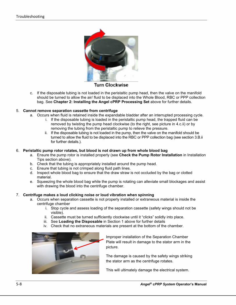
Troubleshooting
5-8 Angel® cPRP System Operator’s Manual
c. If the disposable tubing is not loaded in the peristaltic pump head, then the valve on the manifold
should be turned to allow the air/ fluid to be displaced into the Whole Blood, RBC or PPP collection bag. See Chapter 2: Installing the Angel cPRP Processing Set above for further details.
5. Cannot remove separation cassette from centrifuge
a. Occurs when fluid is retained inside the expandable bladder after an interrupted processing cycle. i. If the disposable tubing is loaded in the peristaltic pump head, the trapped fluid can be
removed by twisting the pump head clockwise (to the right, see picture in 4.c.ii) or by removing the tubing from the peristaltic pump to relieve the pressure.
ii. If the disposable tubing is not loaded in the pump, then the valve on the manifold should be turned to allow the fluid to be displaced into the RBC or PPP collection bag (see section 3.B.ii for further details.).
6. Peristaltic pump rotor rotates, but blood is not drawn up from whole blood bag
a. Ensure the pump rotor is installed properly (see Check the Pump Rotor Installation in Installation Tips section above).
b. Check that the tubing is appropriately installed around the pump head. c. Ensure that tubing is not crimped along fluid path lines. d. Inspect whole blood bag to ensure that the draw straw is not occluded by the bag or clotted
material. e. Squeezing the whole blood bag while the pump is rotating can alleviate small blockages and assist
with drawing the blood into the centrifuge chamber.
7. Centrifuge makes a loud clicking noise or loud vibration when spinning a. Occurs when separation cassette is not properly installed or extraneous material is inside the
centrifuge chamber i. Stop cycle and assess loading of the separation cassette (safety wings should not be
visible). ii. Cassette must be turned sufficiently clockwise until it “clicks” solidly into place. iii. See Loading the Disposable in Section 1 above for further details iv. Check that no extraneous materials are present at the bottom of the chamber.
Improper installation of the Separation Chamber Plate will result in damage to the stator arm in the picture.
The damage is caused by the safety wings striking the stator arm as the centrifuge rotates.
This will ultimately damage the electrical system.
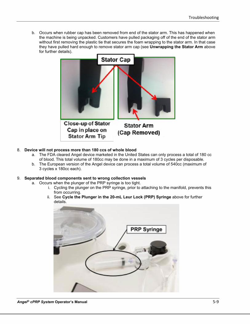
Troubleshooting
Angel® cPRP System Operator’s Manual 5-9
b. Occurs when rubber cap has been removed from end of the stator arm. This has happened when the machine is being unpacked. Customers have pulled packaging off of the end of the stator arm without first removing the plastic tie that secures the foam wrapping to the stator arm. In that case they have pulled hard enough to remove stator arm cap (see Unwrapping the Stator Arm above for further details).
8. Device will not process more than 180 ccs of whole blood a. The FDA cleared Angel device marketed in the United States can only process a total of 180 cc
of blood. This total volume of 180cc may be done in a maximum of 3 cycles per disposable. b. The European version of the Angel device can process a total volume of 540cc (maximum of
3 cycles x 180cc each).
9. Separated blood components sent to wrong collection vessels a. Occurs when the plunger of the PRP syringe is too tight.
i. Cycling the plunger on the PRP syringe, prior to attaching to the manifold, prevents this from occurring.
ii. See Cycle the Plunger in the 20-mL Leur Lock (PRP) Syringe above for further details.
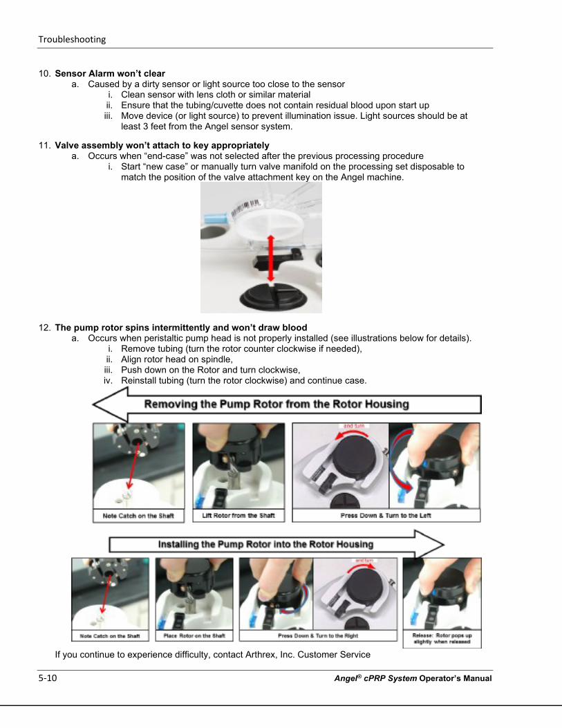
Troubleshooting
5-10 Angel® cPRP System Operator’s Manual
10. Sensor Alarm won’t clear a. Caused by a dirty sensor or light source too close to the sensor
i. Clean sensor with lens cloth or similar material ii. Ensure that the tubing/cuvette does not contain residual blood upon start up iii. Move device (or light source) to prevent illumination issue. Light sources should be at
least 3 feet from the Angel sensor system.
11. Valve assembly won’t attach to key appropriately a. Occurs when “end-case” was not selected after the previous processing procedure
i. Start “new case” or manually turn valve manifold on the processing set disposable to match the position of the valve attachment key on the Angel machine.
12. The pump rotor spins intermittently and won’t draw blood a. Occurs when peristaltic pump head is not properly installed (see illustrations below for details).
i. Remove tubing (turn the rotor counter clockwise if needed), ii. Align rotor head on spindle, iii. Push down on the Rotor and turn clockwise, iv. Reinstall tubing (turn the rotor clockwise) and continue case.
If you continue to experience difficulty, contact Arthrex, Inc. Customer Service
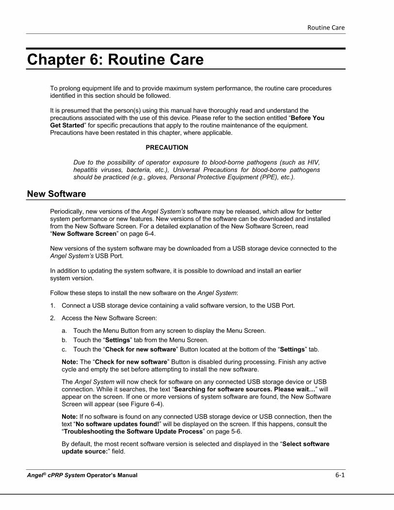
Routine Care
Angel® cPRP System Operator’s Manual 6-1
Chapter 6: Routine Care
To prolong equipment life and to provide maximum system performance, the routine care procedures identified in this section should be followed.
It is presumed that the person(s) using this manual have thoroughly read and understand the precautions associated with the use of this device. Please refer to the section entitled “Before You Get Started” for specific precautions that apply to the routine maintenance of the equipment. Precautions have been restated in this chapter, where applicable.
PRECAUTION
Due to the possibility of operator exposure to blood-borne pathogens (such as HIV, hepatitis viruses, bacteria, etc.), Universal Precautions for blood-borne pathogens should be practiced (e.g., gloves, Personal Protective Equipment (PPE), etc.).
New Software
Periodically, new versions of the Angel System’s software may be released, which allow for better system performance or new features. New versions of the software can be downloaded and installed from the New Software Screen. For a detailed explanation of the New Software Screen, read “New Software Screen” on page 6-4. New versions of the system software may be downloaded from a USB storage device connected to the Angel System’s USB Port. In addition to updating the system software, it is possible to download and install an earlier system version. Follow these steps to install the new software on the Angel System:
1. Connect a USB storage device containing a valid software version, to the USB Port.
2. Access the New Software Screen:
a. Touch the Menu Button from any screen to display the Menu Screen. b. Touch the “Settings” tab from the Menu Screen. c. Touch the “Check for new software” Button located at the bottom of the “Settings” tab.
Note: The “Check for new software” Button is disabled during processing. Finish any active cycle and empty the set before attempting to install the new software.
The Angel System will now check for software on any connected USB storage device or USB connection. While it searches, the text “Searching for software sources. Please wait…” will appear on the screen. If one or more versions of system software are found, the New Software Screen will appear (see Figure 6-4).
Note: If no software is found on any connected USB storage device or USB connection, then the text “No software updates found!” will be displayed on the screen. If this happens, consult the “Troubleshooting the Software Update Process” on page 5-6.
By default, the most recent software version is selected and displayed in the “Select software update source:” field.
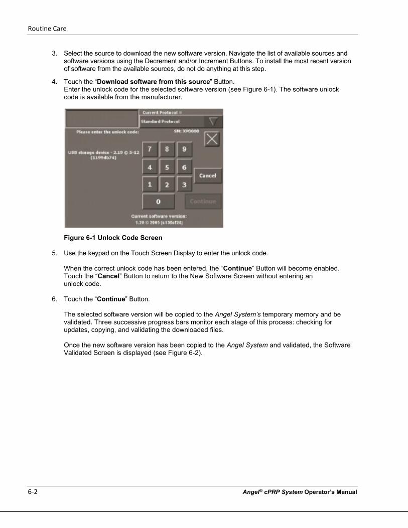
Routine Care
6-2 Angel® cPRP System Operator’s Manual
3. Select the source to download the new software version. Navigate the list of available sources and software versions using the Decrement and/or Increment Buttons. To install the most recent version of software from the available sources, do not do anything at this step.
4. Touch the “Download software from this source” Button. Enter the unlock code for the selected software version (see Figure 6-1). The software unlock code is available from the manufacturer.
Figure 6-1 Unlock Code Screen
5. Use the keypad on the Touch Screen Display to enter the unlock code.
When the correct unlock code has been entered, the “Continue” Button will become enabled. Touch the “Cancel” Button to return to the New Software Screen without entering an unlock code.
6. Touch the “Continue” Button.
The selected software version will be copied to the Angel System’s temporary memory and be validated. Three successive progress bars monitor each stage of this process: checking for updates, copying, and validating the downloaded files.
Once the new software version has been copied to the Angel System and validated, the Software Validated Screen is displayed (see Figure 6-2).
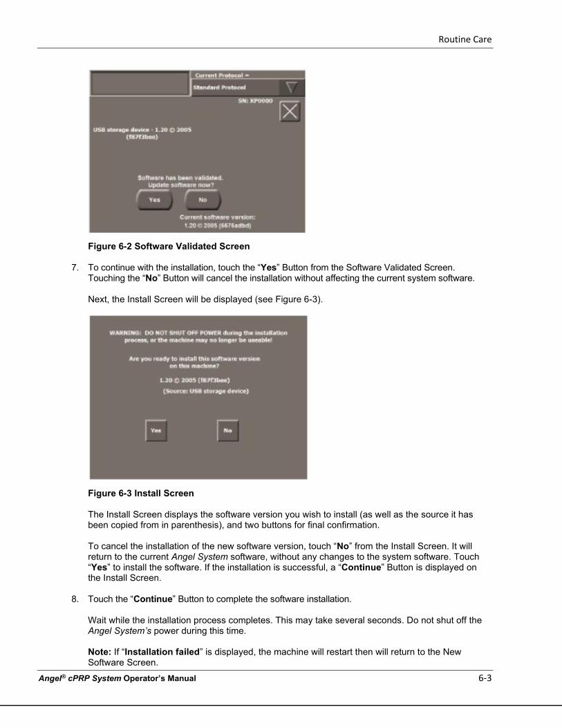
Routine Care
Angel® cPRP System Operator’s Manual 6-3
Figure 6-2 Software Validated Screen
7. To continue with the installation, touch the “Yes” Button from the Software Validated Screen. Touching the “No” Button will cancel the installation without affecting the current system software.
Next, the Install Screen will be displayed (see Figure 6-3).
Figure 6-3 Install Screen
The Install Screen displays the software version you wish to install (as well as the source it has been copied from in parenthesis), and two buttons for final confirmation. To cancel the installation of the new software version, touch “No” from the Install Screen. It will return to the current Angel System software, without any changes to the system software. Touch “Yes” to install the software. If the installation is successful, a “Continue” Button is displayed on the Install Screen.
8. Touch the “Continue” Button to complete the software installation.
Wait while the installation process completes. This may take several seconds. Do not shut off the Angel System’s power during this time. Note: If “Installation failed” is displayed, the machine will restart then will return to the New Software Screen.
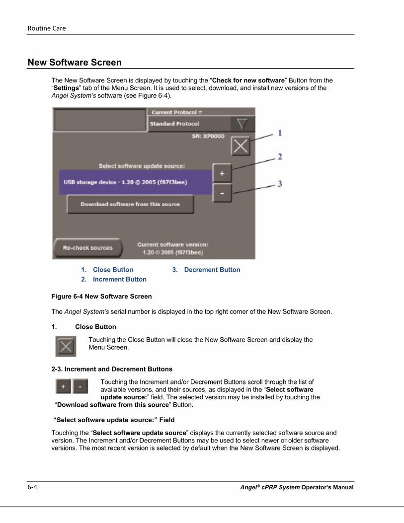
Routine Care
6-4 Angel® cPRP System Operator’s Manual
New Software Screen
The New Software Screen is displayed by touching the “Check for new software” Button from the “Settings” tab of the Menu Screen. It is used to select, download, and install new versions of the Angel System’s software (see Figure 6-4).
1. Close Button 3. Decrement Button 2. Increment Button
Figure 6-4 New Software Screen
The Angel System’s serial number is displayed in the top right corner of the New Software Screen.
1. Close Button
Touching the Close Button will close the New Software Screen and display the Menu Screen.
2-3. Increment and Decrement Buttons
Touching the Increment and/or Decrement Buttons scroll through the list of available versions, and their sources, as displayed in the “Select software update source:” field. The selected version may be installed by touching the
“Download software from this source” Button.
“Select software update source:” Field
Touching the “Select software update source” displays the currently selected software source and version. The Increment and/or Decrement Buttons may be used to select newer or older software versions. The most recent version is selected by default when the New Software Screen is displayed.
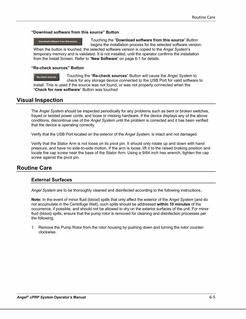
Routine Care
Angel® cPRP System Operator’s Manual 6-5
“Download software from this source” Button
Touching the “Download software from this source” Button begins the installation process for the selected software version.
When the button is touched, the selected software version is copied to the Angel System’s temporary memory and is validated. It is not installed, until the operator confirms the installation from the Install Screen. Refer to “New Software” on page 6-1 for details.
“Re-check sources” Button
Touching the “Re-check sources” Button will cause the Angel System to check for any storage device connected to the USB Port for valid software to
install. This is used if the source was not found, or was not properly connected when the “Check for new software” Button was touched
Visual Inspection
The Angel System should be inspected periodically for any problems such as bent or broken switches, frayed or twisted power cords, and loose or missing hardware. If the device displays any of the above conditions, discontinue use of the Angel System until the problem is corrected and it has been verified that the device is operating correctly. Verify that the USB Port located on the exterior of the Angel System, is intact and not damaged. Verify that the Stator Arm is not loose on its pivot pin. It should only rotate up and down with hand pressure, and have no side-to-side motion. If the arm is loose, lift it to the raised braking position and locate the cap screw near the base of the Stator Arm. Using a 9/64 inch hex wrench, tighten the cap screw against the pivot pin.
Routine Care
External Surfaces
Angel System are to be thoroughly cleaned and disinfected according to the following instructions.. Note: In the event of minor fluid (blood) spills that only affect the exterior of the Angel System (and do not accumulate in the Centrifuge Well), such spills should be addressed within 10 minutes of the occurrence, if possible, and should not be allowed to dry on the exterior surfaces of the unit. For minor fluid (blood) spills, ensure that the pump rotor is removed for cleaning and disinfection processes per the following. 1. Remove the Pump Rotor from the rotor housing by pushing down and turning the rotor counter-
clockwise.
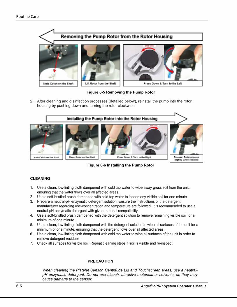
Routine Care
6-6 Angel® cPRP System Operator’s Manual
Figure 6-5 Removing the Pump Rotor
2. After cleaning and disinfection processes (detailed below), reinstall the pump into the rotor housing by pushing down and turning the rotor clockwise.
Figure 6-6 Installing the Pump Rotor
CLEANING 1. Use a clean, low-linting cloth dampened with cold tap water to wipe away gross soil from the unit,
ensuring that the water flows over all affected areas. 2. Use a soft-bristled brush dampened with cold tap water to loosen any visible soil for one minute. 3. Prepare a neutral-pH enzymatic detergent solution. Ensure the instructions of the detergent
manufacturer regarding use-concentration and temperature are followed. It is recommended to use a neutral-pH enzymatic detergent with given material compatibility.
4. Use a soft-bristled brush dampened with the detergent solution to remove remaining visible soil for a minimum of one minute.
5. Use a clean, low-linting cloth dampened with the detergent solution to wipe all surfaces of the unit for a minimum of one minute, ensuring that the detergent flows over all affected areas.
6. Use a clean, low-linting cloth dampened with cold tap water to wipe all surfaces of the unit in order to remove detergent residues.
7. Check all surfaces for visible soil. Repeat cleaning steps if soil is visible and re-inspect.
PRECAUTION
When cleaning the Platelet Sensor, Centrifuge Lid and Touchscreen areas, use a neutral-pH enzymatic detergent. Do not use bleach, abrasive materials or solvents, as they may cause damage to the sensor.
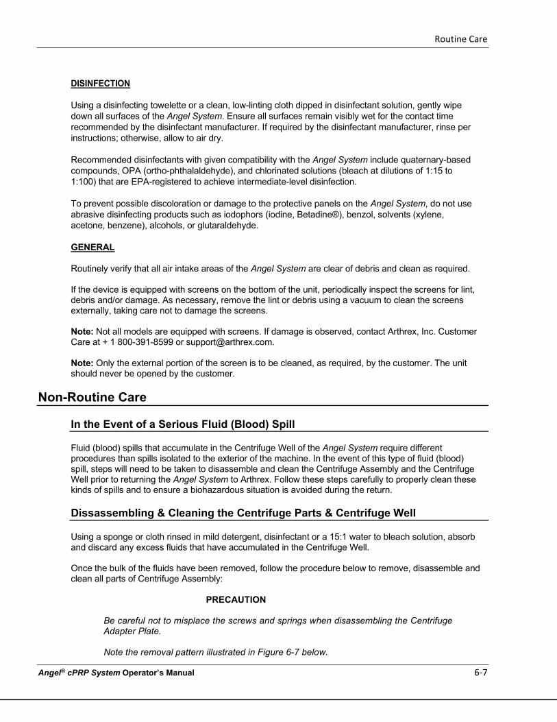
Routine Care
Angel® cPRP System Operator’s Manual 6-7
DISINFECTION Using a disinfecting towelette or a clean, low-linting cloth dipped in disinfectant solution, gently wipe down all surfaces of the Angel System. Ensure all surfaces remain visibly wet for the contact time recommended by the disinfectant manufacturer. If required by the disinfectant manufacturer, rinse per instructions; otherwise, allow to air dry. Recommended disinfectants with given compatibility with the Angel System include quaternary-based compounds, OPA (ortho-phthalaldehyde), and chlorinated solutions (bleach at dilutions of 1:15 to 1:100) that are EPA-registered to achieve intermediate-level disinfection. To prevent possible discoloration or damage to the protective panels on the Angel System, do not use abrasive disinfecting products such as iodophors (iodine, Betadine®), benzol, solvents (xylene, acetone, benzene), alcohols, or glutaraldehyde. GENERAL
Routinely verify that all air intake areas of the Angel System are clear of debris and clean as required. If the device is equipped with screens on the bottom of the unit, periodically inspect the screens for lint, debris and/or damage. As necessary, remove the lint or debris using a vacuum to clean the screens externally, taking care not to damage the screens. Note: Not all models are equipped with screens. If damage is observed, contact Arthrex, Inc. Customer Care at + 1 800-391-8599 or [email protected]. Note: Only the external portion of the screen is to be cleaned, as required, by the customer. The unit should never be opened by the customer.
Non-Routine Care
In the Event of a Serious Fluid (Blood) Spill
Fluid (blood) spills that accumulate in the Centrifuge Well of the Angel System require different procedures than spills isolated to the exterior of the machine. In the event of this type of fluid (blood) spill, steps will need to be taken to disassemble and clean the Centrifuge Assembly and the Centrifuge Well prior to returning the Angel System to Arthrex. Follow these steps carefully to properly clean these kinds of spills and to ensure a biohazardous situation is avoided during the return.
Dissassembling & Cleaning the Centrifuge Parts & Centrifuge Well
Using a sponge or cloth rinsed in mild detergent, disinfectant or a 15:1 water to bleach solution, absorb and discard any excess fluids that have accumulated in the Centrifuge Well. Once the bulk of the fluids have been removed, follow the procedure below to remove, disassemble and clean all parts of Centrifuge Assembly:
PRECAUTION
Be careful not to misplace the screws and springs when disassembling the Centrifuge Adapter Plate. Note the removal pattern illustrated in Figure 6-7 below.
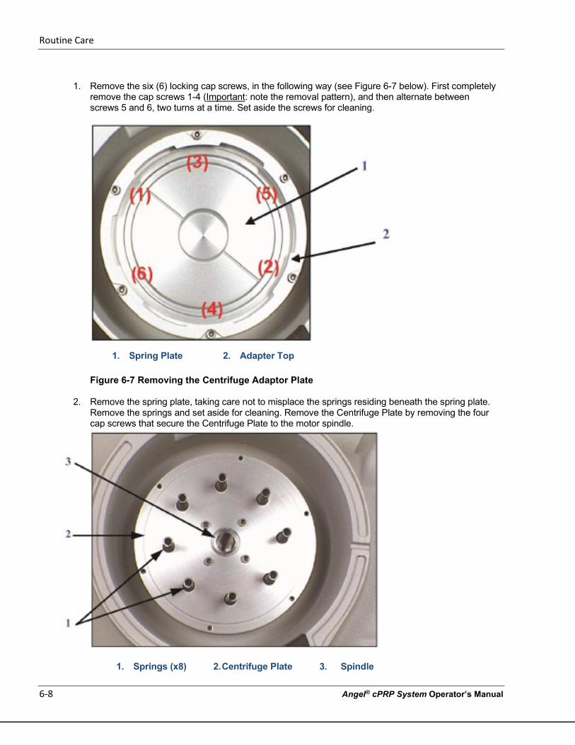
Routine Care
6-8 Angel® cPRP System Operator’s Manual
1. Remove the six (6) locking cap screws, in the following way (see Figure 6-7 below). First completely
remove the cap screws 1-4 (Important: note the removal pattern), and then alternate between screws 5 and 6, two turns at a time. Set aside the screws for cleaning.
1. Spring Plate 2. Adapter Top
Figure 6-7 Removing the Centrifuge Adaptor Plate
2. Remove the spring plate, taking care not to misplace the springs residing beneath the spring plate. Remove the springs and set aside for cleaning. Remove the Centrifuge Plate by removing the four cap screws that secure the Centrifuge Plate to the motor spindle.
1. Springs (x8) 2. Centrifuge Plate 3. Spindle
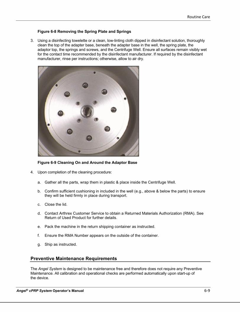
Routine Care
Angel® cPRP System Operator’s Manual 6-9
Figure 6-8 Removing the Spring Plate and Springs
3. Using a disinfecting towelette or a clean, low-linting cloth dipped in disinfectant solution, thoroughly clean the top of the adapter base, beneath the adapter base in the well, the spring plate, the adaptor top, the springs and screws, and the Centrifuge Well. Ensure all surfaces remain visibly wet for the contact time recommended by the disinfectant manufacturer. If required by the disinfectant manufacturer, rinse per instructions; otherwise, allow to air dry.
Figure 6-9 Cleaning On and Around the Adaptor Base
4. Upon completion of the cleaning procedure:
a. Gather all the parts, wrap them in plastic & place inside the Centrifuge Well.
b. Confirm sufficient cushioning in included in the well (e.g., above & below the parts) to ensure they will be held firmly in place during transport.
c. Close the lid.
d. Contact Arthrex Customer Service to obtain a Returned Materials Authorization (RMA). See Return of Used Product for further details.
e. Pack the machine in the return shipping container as instructed.
f. Ensure the RMA Number appears on the outside of the container.
g. Ship as instructed.
Preventive Maintenance Requirements
The Angel System is designed to be maintenance free and therefore does not require any Preventive Maintenance. All calibration and operational checks are performed automatically upon start-up of the device.
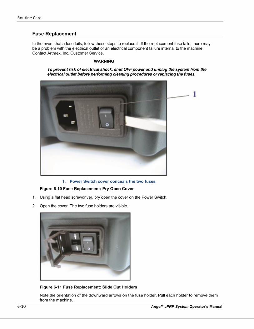
Routine Care
6-10 Angel® cPRP System Operator’s Manual
Fuse Replacement
In the event that a fuse fails, follow these steps to replace it. If the replacement fuse fails, there may be a problem with the electrical outlet or an electrical component failure internal to the machine. Contact Arthrex, Inc. Customer Service.
WARNING
To prevent risk of electrical shock, shut OFF power and unplug the system from the electrical outlet before performing cleaning procedures or replacing the fuses.
1. Power Switch cover conceals the two fuses
Figure 6-10 Fuse Replacement: Pry Open Cover
1. Using a flat head screwdriver, pry open the cover on the Power Switch.
2. Open the cover. The two fuse holders are visible.
Figure 6-11 Fuse Replacement: Slide Out Holders
Note the orientation of the downward arrows on the fuse holder. Pull each holder to remove them from the machine.
Routine Care
Angel® cPRP System Operator’s Manual 6-11
3. Replace the fuses with fuses of the identical specifications (5 x 20 mm size, 2X F 5A L 250VAC fast
blow). These can be obtained at any electronic parts retailer.
4. Reverse the removal steps to re-install.

Routine Care
6-12 Angel® cPRP System Operator’s Manual
This page intentionally left blank
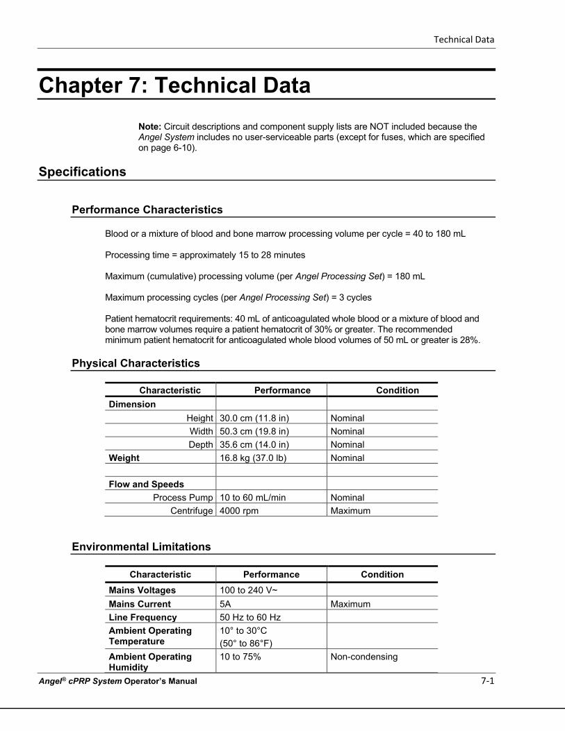
Technical Data
Angel® cPRP System Operator’s Manual 7-1
Chapter 7: Technical Data
Note: Circuit descriptions and component supply lists are NOT included because the Angel System includes no user-serviceable parts (except for fuses, which are specified on page 6-10).
Specifications
Performance Characteristics
Blood or a mixture of blood and bone marrow processing volume per cycle = 40 to 180 mL Processing time = approximately 15 to 28 minutes Maximum (cumulative) processing volume (per Angel Processing Set) = 180 mL Maximum processing cycles (per Angel Processing Set) = 3 cycles Patient hematocrit requirements: 40 mL of anticoagulated whole blood or a mixture of blood and bone marrow volumes require a patient hematocrit of 30% or greater. The recommended minimum patient hematocrit for anticoagulated whole blood volumes of 50 mL or greater is 28%.
Physical Characteristics
Characteristic Performance Condition
Dimension Height 30.0 cm (11.8 in) Nominal Width 50.3 cm (19.8 in) Nominal Depth 35.6 cm (14.0 in) Nominal
Weight 16.8 kg (37.0 lb) Nominal Flow and Speeds
Process Pump 10 to 60 mL/min Nominal Centrifuge 4000 rpm Maximum
Environmental Limitations
Characteristic Performance Condition Mains Voltages 100 to 240 V~ Mains Current 5A Maximum Line Frequency 50 Hz to 60 Hz Ambient Operating Temperature
10° to 30°C (50° to 86°F)
Ambient Operating Humidity
10 to 75% Non-condensing
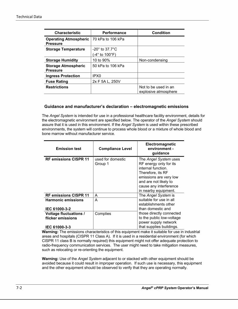
Technical Data
7-2 Angel® cPRP System Operator’s Manual
Characteristic Performance Condition Operating Atmospheric Pressure
70 kPa to 106 kPa
Storage Temperature -20° to 37.7°C (-4° to 100°F)
Storage Humidity 10 to 90% Non-condensing Storage Atmospheric Pressure
50 kPa to 106 kPa
Ingress Protection IPX0 Fuse Rating 2x F 5A L, 250V Restrictions Not to be used in an
explosive atmosphere
Guidance and manufacturer’s declaration – electromagnetic emissions
The Angel System is intended for use in a professional healthcare facility environment, details for the electromagnetic environment are specified below. The operator of the Angel System should assure that it is used in this environment. If the Angel System is used within these prescribed environments, the system will continue to process whole blood or a mixture of whole blood and bone marrow without manufacturer service.
Emission test Compliance Level Electromagnetic
environment - guidance
RF emissions CISPR 11 used for domestic Group 1
The Angel System uses RF energy only for its internal function. Therefore, its RF emissions are very low and are not likely to cause any interference in nearby equipment.
RF emissions CISPR 11 A The Angel System is suitable for use in all establishments other than domestic and those directly connected to the public low-voltage power supply network that supplies buildings.
Harmonic emissions IEC 61000-3-2
A
Voltage fluctuations / flicker emissions IEC 61000-3-3
Complies
Warning: The emissions characteristics of this equipment make it suitable for use in industrial areas and hospitals (CISPR 11 Class A). If it is used in a residential environment (for which CISPR 11 class B is normally required) this equipment might not offer adequate protection to radio-frequency communication services. The user might need to take mitigation measures, such as relocating or re-orienting the equipment. Warning: Use of the Angel System adjacent to or stacked with other equipment should be avoided because it could result in improper operation. If such use is necessary, this equipment and the other equipment should be observed to verify that they are operating normally.
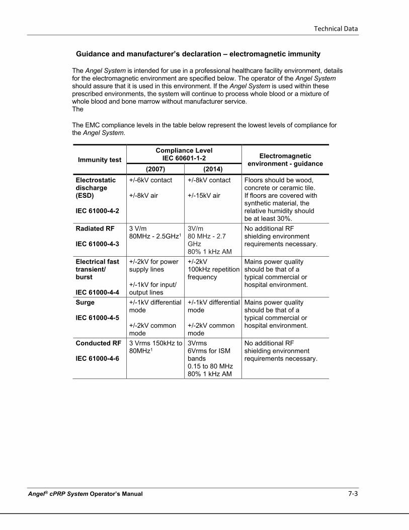
Technical Data
Angel® cPRP System Operator’s Manual 7-3
Guidance and manufacturer’s declaration – electromagnetic immunity
The Angel System is intended for use in a professional healthcare facility environment, details for the electromagnetic environment are specified below. The operator of the Angel System should assure that it is used in this environment. If the Angel System is used within these prescribed environments, the system will continue to process whole blood or a mixture of whole blood and bone marrow without manufacturer service. The
The EMC compliance levels in the table below represent the lowest levels of compliance for the Angel System.
Immunity test Compliance Level
IEC 60601-1-2 Electromagnetic environment - guidance
(2007) (2014) Electrostatic discharge (ESD)
IEC 61000-4-2
+/-6kV contact +/-8kV air
+/-8kV contact +/-15kV air
Floors should be wood, concrete or ceramic tile. If floors are covered with synthetic material, the relative humidity should be at least 30%.
Radiated RF IEC 61000-4-3
3 V/m 80MHz - 2.5GHz1
3V/m 80 MHz - 2.7 GHz 80% 1 kHz AM
No additional RF shielding environment requirements necessary.
Electrical fast transient/ burst
IEC 61000-4-4
+/-2kV for power supply lines +/-1kV for input/ output lines
+/-2kV 100kHz repetition frequency
Mains power quality should be that of a typical commercial or hospital environment.
Surge IEC 61000-4-5
+/-1kV differential mode +/-2kV common mode
+/-1kV differential mode +/-2kV common mode
Mains power quality should be that of a typical commercial or hospital environment.
Conducted RF IEC 61000-4-6
3 Vrms 150kHz to 80MHz1
3Vrms 6Vrms for ISM bands 0.15 to 80 MHz 80% 1 kHz AM
No additional RF shielding environment requirements necessary.

Technical Data
7-4 Angel® cPRP System Operator’s Manual
Immunity test Compliance Level
IEC 60601-1-2 Electromagnetic environment - guidance
(2007) (2014) Voltage dips, short interruptions and voltage variations on power supply input lines IEC 61000-4-11
<5% UT (>95% dip in UT) for 0.5 cycle 40% UT (60% dip in UT) For 5 cycles 70% UT (30% dip in UT) For 25 cycles <5% UT (>95% dip in UT) For 5 sec
0% UT (1005% dip in UT) for 0.5 cycle at 0, 45, 90, 135, 180, 225, 270 and 315º 0% UT (100% dip in UT) For 1 cycle at 0º 70% UT (30% dip in UT) For 25 cycles (50Hz) and 30 cycles (60Hz) at 0º 0% UT (100% dip in UT) For 250 cycles (50Hz) and 300 cycles (60 Hz) at 0º
Mains power quality should be that of a typical commercial or hospital environment. If the user of the Angel System requires continued operation during power mains interruptions, it is recommended that the Angel System be powered from an uninterruptible power supply or a battery.
Power frequency (50 / 60 Hz) magnetic field IEC 61000-4-8
3 A/m 30 A/m Power frequency magnetic fields should be at levels characteristic of a typical location in a typical commercial or hospital environment.
Note: UT is the a.c. mains voltage prior to application of the test level. 1See Recommended separation distances between portable and mobile RF communications equipment and the Angel System below for further information
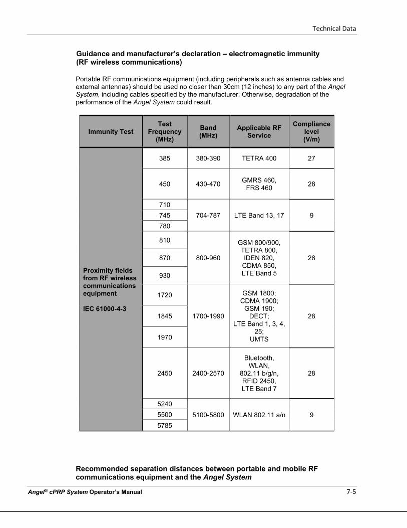
Technical Data
Angel® cPRP System Operator’s Manual 7-5
Guidance and manufacturer’s declaration – electromagnetic immunity (RF wireless communications)
Portable RF communications equipment (including peripherals such as antenna cables and external antennas) should be used no closer than 30cm (12 inches) to any part of the Angel System, including cables specified by the manufacturer. Otherwise, degradation of the performance of the Angel System could result.
Immunity Test Test
Frequency (MHz)
Band (MHz)
Applicable RF Service
Compliance level (V/m)
Proximity fields from RF wireless communications equipment IEC 61000-4-3
385 380-390 TETRA 400 27
450 430-470 GMRS 460, FRS 460 28
710 704-787 LTE Band 13, 17 9 745
780
810
800-960
GSM 800/900, TETRA 800, IDEN 820, CDMA 850, LTE Band 5
28 870
930
1720
1700-1990
GSM 1800; CDMA 1900;
GSM 190; DECT;
LTE Band 1, 3, 4, 25;
UMTS
28 1845
1970
2450 2400-2570
Bluetooth, WLAN,
802.11 b/g/n, RFID 2450, LTE Band 7
28
5240 5100-5800 WLAN 802.11 a/n 9 5500
5785
Recommended separation distances between portable and mobile RF communications equipment and the Angel System
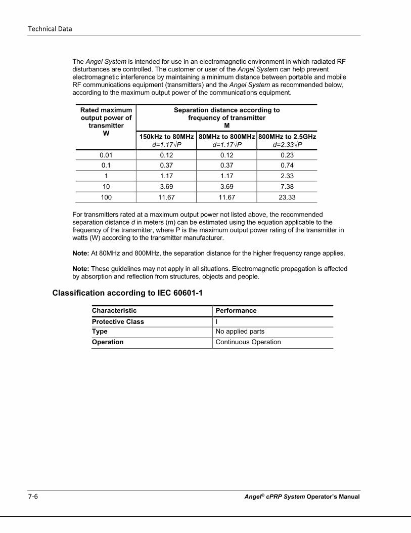
Technical Data
7-6 Angel® cPRP System Operator’s Manual
The Angel System is intended for use in an electromagnetic environment in which radiated RF disturbances are controlled. The customer or user of the Angel System can help prevent electromagnetic interference by maintaining a minimum distance between portable and mobile RF communications equipment (transmitters) and the Angel System as recommended below, according to the maximum output power of the communications equipment.
Rated maximum output power of
transmitter W
Separation distance according to frequency of transmitter
M 150kHz to 80MHz
d=1.17√P 80MHz to 800MHz
d=1.17√P 800MHz to 2.5GHz
d=2.33√P 0.01 0.12 0.12 0.23 0.1 0.37 0.37 0.74 1 1.17 1.17 2.33
10 3.69 3.69 7.38 100 11.67 11.67 23.33
For transmitters rated at a maximum output power not listed above, the recommended separation distance d in meters (m) can be estimated using the equation applicable to the frequency of the transmitter, where P is the maximum output power rating of the transmitter in watts (W) according to the transmitter manufacturer.
Note: At 80MHz and 800MHz, the separation distance for the higher frequency range applies.
Note: These guidelines may not apply in all situations. Electromagnetic propagation is affected by absorption and reflection from structures, objects and people.
Classification according to IEC 60601-1
Characteristic Performance Protective Class I Type No applied parts Operation Continuous Operation
Other Commercial Matters
Angel® cPRP System Operator’s Manual 8-1
Chapter 8: Other Commercial Matters
This is not a warranty document. For all warranty information, including disclaimers, exclusions, terms, conditions and related provisions refer to the “Arthrex U.S. Product Warranty” section of the Arthrex, Inc.
website, found at www.arthrex.com whose provisions are incorporated herein by reference.
Limitation of Liability
NEITHER ARTHREX, INC. NOR THE MANUFACTURER WILL HAVE ANY RESPONSIBILITY FOR INCIDENTAL OR CONSEQUENTIAL DAMAGES, WHETHER FOR BREACH OF WARRANTY OR OTHER CONTRACT, NEGLIGENCE OR OTHER TORT OR ON ANY STRICT LIABILITY THEORY.
Technical documentation
a) Products are always supplied complete with adequate documentation, including, inter alia, instructions for correct use, as well as the list of routine care activities. Other details may concern any disposables needed for correct use of the device.
b) All the documentation and information, drawings and descriptions contained in the manual or, for whatever reason, provided to the user, shall be considered as confidential and as belonging exclusively to Arthrex, Inc. These shall not therefore be revealed, distributed, copied or reproduced by any means and for whatever purpose, nor given out for consultation, total or partial, to anyone, without specific prior authorization being formally given by the manufacturer.
c) The manufacturer reserves the right to make, without prior notice, amendments or updates
to the contents of previously distributed documentation.
Technical safety standards
a) The safety standards applicable to the manufacture of the Angel System shall be those enforced in the Country where the device is addressed by the Manufacturer at the time of marketing of such device.
b) In Europe, safety with regard to electrical and mechanical hazards, explosions and fires, relative to medical electrical equipment, is defined by the following harmonized standard: EN 60601-1: Medical electrical equipment - Part 1: general requirements for safety which implements the requirements of the International Standard IEC 601-1: Safety of medical electrical equipment-Part 1: general requirements issued by I.E.C., International Electrotechnical Committee, and already transposed by C.E.I., Comitato Elettrot ecnico Italiano, such as: CEI 62-5: Apparecchi elettromedicali-Parte 1: nor me generali per la sicurezza Such standards apply to medical electrical equipment intended for use by or under the control of qualified personnel in the immediate proximity of the patient and in relation to the patient him/herself (in this context, proximity means the area within 2.5 m from the patient).
Other Commercial Matters
8-2 Angel® cPRP System Operator’s Manual
c) Each product undergoes safety tests as prescribed by the relevant standards, the results of which are available upon request.
d) Any requests for specific measurements of safety parameters different from those above
quoted shall be analyzed and assessed by the manufacturer as appropriate.
Other Commercial Matters
Angel® cPRP System Operator’s Manual 8-3
Identification of manufacturer
Please feel free to contact Arthrex, Inc. for any further details and/or technical assistance.
Arthrex, Inc. 1370 Creekside Blvd Naples, FL 34108 USA Tel: + 1 800-391-8599 [email protected] www.arthrex.com
Other Commercial Matters
Angel® cPRP System Operator’s Manual
Copyright © 2020
Arthrex, Inc. 1370 Creekside Blvd Naples, FL 34108 USA Tel: + 1 800-391-8599 [email protected] www.arthrex.com
DFU-0262-3 Revision 0 06/2020


