Embed Size (px)
Citation preview
AIX Storage Management
Document Number GG24-4484-00
October 24, 1994
International Technical Support OrganizationAustin Center
Take Note!
Before using this information and the product it supports, be sure to read the general information under“Special Notices” on page xiii.
First Edition (October 24, 1994)
This edition applies to the AIX Version 3.2 operating system, and where applicable to AIX Version 4.1.
Order publications through your IBM representative or the IBM branch office serving your locality. Publicationsare not stocked at the address given below.
An ITSO Technical Bulletin Evaluation Form for reader′s feedback appears facing Chapter 1. If the form has beenremoved, comments may be addressed to:
IBM Corporation, International Technical Support OrganizationDept. 632B Building 821 Internal Zip 283411400 Burnet RoadAustin, Texas 78758-3493
When you send information to IBM, you grant IBM a non-exclusive right to use or distribute the information in anyway it believes appropriate without incurring any obligation to you.
Copyright International Business Machines Corporation 1994. All rights reserved.Note to U.S. Government Users — Documentation related to restricted rights — Use, duplication or disclosure issubject to restrictions set forth in GSA ADP Schedule Contract with IBM Corp.
Abstract
This document provides a general introduction to storage management using AIXon the RISC System/6000. Concepts and terminology are covered beforedescribing in more detail the operating system components: the Logical VolumeManager, and file systems. Using this foundation, it then describes the additionalfeatures and functions provided with AIX Version 4; useful commands are alsodetailed, as well as a guide to designing storage subsystems. In order toillustrate the topics covered, and provide examples of common practicalapplication, a section containing detailed step by step information on a variety ofstorage management tasks is included.
This document is intended for customers and systems engineers who require amore detailed understanding of storage management with AIX on the RISCSystem/6000, particularly the additional features provided with AIX Version 4,and who wish to have access to practical examples. Some knowledge of AIXVersion 3 is assumed.
(367 pages)
Copyright IBM Corp. 1994 iii

iv AIX Storage Management
Contents
Abstract . . . . . . . . . . . . . . . . . . . . . . . . . . . . . . . . . . . . . . . . . . i i i
Special Notices . . . . . . . . . . . . . . . . . . . . . . . . . . . . . . . . . . . . . xii i
Preface . . . . . . . . . . . . . . . . . . . . . . . . . . . . . . . . . . . . . . . . . . xvHow This Document is Organized . . . . . . . . . . . . . . . . . . . . . . . . . . xvRelated Publications . . . . . . . . . . . . . . . . . . . . . . . . . . . . . . . . . xviiInternational Technical Support Organization Publications . . . . . . . . . . . xviiAcknowledgments . . . . . . . . . . . . . . . . . . . . . . . . . . . . . . . . . . xviii
Chapter 1. Storage Management Related Concepts . . . . . . . . . . . . . . . . 11.1 Overview . . . . . . . . . . . . . . . . . . . . . . . . . . . . . . . . . . . . . . . 1
1.1.1 General Concepts . . . . . . . . . . . . . . . . . . . . . . . . . . . . . . . 11.1.2 Hardware Concepts . . . . . . . . . . . . . . . . . . . . . . . . . . . . . . 31.1.3 Software Concepts . . . . . . . . . . . . . . . . . . . . . . . . . . . . . . 6
1.2 Storage Management . . . . . . . . . . . . . . . . . . . . . . . . . . . . . . . 81.2.1 Hardware Management . . . . . . . . . . . . . . . . . . . . . . . . . . . 81.2.2 Software Management . . . . . . . . . . . . . . . . . . . . . . . . . . . . 12
1.3 Summary . . . . . . . . . . . . . . . . . . . . . . . . . . . . . . . . . . . . . . . 15
Chapter 2. Hardware Storage Components . . . . . . . . . . . . . . . . . . . . . 172.1 Selecting the Hardware Components . . . . . . . . . . . . . . . . . . . . . . 17
2.1.1 Points to Consider . . . . . . . . . . . . . . . . . . . . . . . . . . . . . . 172.1.2 How to Make the Decision . . . . . . . . . . . . . . . . . . . . . . . . . . 18
2.2 Selecting the Physical Hardware Devices . . . . . . . . . . . . . . . . . . . 222.2.1 Hardware Attachment Adapters . . . . . . . . . . . . . . . . . . . . . . 222.2.2 Disk Storage . . . . . . . . . . . . . . . . . . . . . . . . . . . . . . . . . . 252.2.3 Tape Storage . . . . . . . . . . . . . . . . . . . . . . . . . . . . . . . . . . 342.2.4 Optical Storage . . . . . . . . . . . . . . . . . . . . . . . . . . . . . . . . 40
2.3 Summary . . . . . . . . . . . . . . . . . . . . . . . . . . . . . . . . . . . . . . . 44
Chapter 3. Operating System Software Components . . . . . . . . . . . . . . . 473.1 The Operating System . . . . . . . . . . . . . . . . . . . . . . . . . . . . . . . 47
3.1.1 Page Space . . . . . . . . . . . . . . . . . . . . . . . . . . . . . . . . . . 473.1.2 Device Drivers . . . . . . . . . . . . . . . . . . . . . . . . . . . . . . . . . 513.1.3 Logical Volume Manager . . . . . . . . . . . . . . . . . . . . . . . . . . 513.1.4 File Systems . . . . . . . . . . . . . . . . . . . . . . . . . . . . . . . . . . 58
3.2 Higher Level Tools . . . . . . . . . . . . . . . . . . . . . . . . . . . . . . . . . 643.2.1 Backup/Restore . . . . . . . . . . . . . . . . . . . . . . . . . . . . . . . . 643.2.2 Hierarchical Storage Management . . . . . . . . . . . . . . . . . . . . . 653.2.3 Media Management . . . . . . . . . . . . . . . . . . . . . . . . . . . . . . 66
3.3 Summary . . . . . . . . . . . . . . . . . . . . . . . . . . . . . . . . . . . . . . . 66
Chapter 4. AIX Version 4 Storage Management Enhancements . . . . . . . . . 694.1 Fragmentation . . . . . . . . . . . . . . . . . . . . . . . . . . . . . . . . . . . . 69
4.1.1 Disk Space Allocation . . . . . . . . . . . . . . . . . . . . . . . . . . . . 714.1.2 Free Space Fragmentation . . . . . . . . . . . . . . . . . . . . . . . . . . 724.1.3 Fragment Allocation Map . . . . . . . . . . . . . . . . . . . . . . . . . . 72
4.2 Compression . . . . . . . . . . . . . . . . . . . . . . . . . . . . . . . . . . . . 724.2.1 Implementation of Data Compression . . . . . . . . . . . . . . . . . . . 734.2.2 Compression Algorithm . . . . . . . . . . . . . . . . . . . . . . . . . . . 73
Copyright IBM Corp. 1994 v
4.3 Disk Striping . . . . . . . . . . . . . . . . . . . . . . . . . . . . . . . . . . . . . 744.3.1 Usage Implications . . . . . . . . . . . . . . . . . . . . . . . . . . . . . . 76
4.4 Using Page Space for System Dumps . . . . . . . . . . . . . . . . . . . . . 764.5 Variable I-nodes . . . . . . . . . . . . . . . . . . . . . . . . . . . . . . . . . . 774.6 File System Maximum Size Increase . . . . . . . . . . . . . . . . . . . . . . 77
4.6.1 JFS Log Considerations . . . . . . . . . . . . . . . . . . . . . . . . . . . 784.7 Summary . . . . . . . . . . . . . . . . . . . . . . . . . . . . . . . . . . . . . . . 78
Chapter 5. Storage Subsystem Design . . . . . . . . . . . . . . . . . . . . . . . 795.1 Introduction . . . . . . . . . . . . . . . . . . . . . . . . . . . . . . . . . . . . . 795.2 Planning Disk Utilization . . . . . . . . . . . . . . . . . . . . . . . . . . . . . 79
5.2.1 Volume Groups . . . . . . . . . . . . . . . . . . . . . . . . . . . . . . . . 795.2.2 Physical Volumes . . . . . . . . . . . . . . . . . . . . . . . . . . . . . . . 805.2.3 Logical Volumes . . . . . . . . . . . . . . . . . . . . . . . . . . . . . . . . 815.2.4 File Systems . . . . . . . . . . . . . . . . . . . . . . . . . . . . . . . . . . 81
5.3 Planning for Performance . . . . . . . . . . . . . . . . . . . . . . . . . . . . . 825.4 Planning for Availability . . . . . . . . . . . . . . . . . . . . . . . . . . . . . . 865.5 Planning Backup Strategies . . . . . . . . . . . . . . . . . . . . . . . . . . . 89
5.5.1 Backup Overview . . . . . . . . . . . . . . . . . . . . . . . . . . . . . . . 895.5.2 Backup Planning . . . . . . . . . . . . . . . . . . . . . . . . . . . . . . . 905.5.3 Backup Methods . . . . . . . . . . . . . . . . . . . . . . . . . . . . . . . . 915.5.4 Backup Media . . . . . . . . . . . . . . . . . . . . . . . . . . . . . . . . . 91
5.6 Summary . . . . . . . . . . . . . . . . . . . . . . . . . . . . . . . . . . . . . . . 92
Chapter 6. General AIX Storage Management . . . . . . . . . . . . . . . . . . . 956.1 Introduction . . . . . . . . . . . . . . . . . . . . . . . . . . . . . . . . . . . . . 956.2 Managing Physical Volumes . . . . . . . . . . . . . . . . . . . . . . . . . . . 95
6.2.1 Configuration of Physical Volumes . . . . . . . . . . . . . . . . . . . . . 966.2.2 Modifying Physical Volume Characteristics . . . . . . . . . . . . . . . . 966.2.3 Removing Physical Volumes . . . . . . . . . . . . . . . . . . . . . . . . 976.2.4 Monitoring Physical Volumes . . . . . . . . . . . . . . . . . . . . . . . . 986.2.5 Listing Information about Physical Volumes . . . . . . . . . . . . . . . 99
6.3 Managing Volume Groups . . . . . . . . . . . . . . . . . . . . . . . . . . . 1036.3.1 Adding a Volume Group . . . . . . . . . . . . . . . . . . . . . . . . . . 1036.3.2 Modifying Volume Group Characteristics . . . . . . . . . . . . . . . . 1046.3.3 Importing and Exporting a Volume Group . . . . . . . . . . . . . . . . 1066.3.4 Varying On and Varying Off Volume Groups . . . . . . . . . . . . . . 1086.3.5 Monitoring Volume Groups . . . . . . . . . . . . . . . . . . . . . . . . 109
6.4 Managing Logical Volumes . . . . . . . . . . . . . . . . . . . . . . . . . . . 1136.4.1 Adding a Logical Volume . . . . . . . . . . . . . . . . . . . . . . . . . 1146.4.2 Removing a Logical Volume . . . . . . . . . . . . . . . . . . . . . . . . 1146.4.3 Increasing the Size of a Logical Volume . . . . . . . . . . . . . . . . 1156.4.4 Copying a Logical Volume . . . . . . . . . . . . . . . . . . . . . . . . . 1166.4.5 Migrating and Reorganizing Logical Volumes . . . . . . . . . . . . . 1166.4.6 Listing a Logical Volume . . . . . . . . . . . . . . . . . . . . . . . . . . 1176.4.7 Listing a Summary of a Logical Volume Allocation . . . . . . . . . . 1186.4.8 Reading the VGDA on a Physical Volume . . . . . . . . . . . . . . . 119
6.5 Managing the Storage Environment . . . . . . . . . . . . . . . . . . . . . . 1196.5.1 Disk Space and Performance/Availability Management . . . . . . . 1206.5.2 Backup and Restore Management . . . . . . . . . . . . . . . . . . . . 127
6.6 Summary . . . . . . . . . . . . . . . . . . . . . . . . . . . . . . . . . . . . . . 135
Chapter 7. Storage Management Files and Commands Summary . . . . . . 1397.1 How to Understand and Use this Chapter . . . . . . . . . . . . . . . . . . 139
7.1.1 Major AIX Version 4 Filesets Relevant to Storage Management . . 140
vi AIX Storage Management
7.2 Common Storage Management Commands Using AIX Version 3 Syntax 1417.2.1 Using Logical Volume Manager Files . . . . . . . . . . . . . . . . . . 1417.2.2 Using File System Administration Commands . . . . . . . . . . . . . 1517.2.3 Using System Backup and BOS Installation Utilities . . . . . . . . . 1547.2.4 Using Archive Commands . . . . . . . . . . . . . . . . . . . . . . . . . 1557.2.5 Using Other Fileset Commands . . . . . . . . . . . . . . . . . . . . . . 159
7.3 AIX Version 4 Specific File Features . . . . . . . . . . . . . . . . . . . . . 1597.3.1 Using Logical Volume Manager Files in an AIX Version 4
Environment . . . . . . . . . . . . . . . . . . . . . . . . . . . . . . . . . . . . 1597.3.2 Using File System Administration Commands in an AIX Version 4
Environment . . . . . . . . . . . . . . . . . . . . . . . . . . . . . . . . . . . . 1617.3.3 Using System Backup and BOS Installation Utilities in an AIX
Version 4 Environment . . . . . . . . . . . . . . . . . . . . . . . . . . . . . . 1627.3.4 Using Archive Commands in an AIX Version 4 Environment . . . . 164
7.4 Using Commands to View AIX Version 4 Logical Volume ManagerInformation . . . . . . . . . . . . . . . . . . . . . . . . . . . . . . . . . . . . . . 165
7.5 Using Commands to View AIX Version 4 Journaled File SystemInformation . . . . . . . . . . . . . . . . . . . . . . . . . . . . . . . . . . . . . . 181
Chapter 8. Practical Examples . . . . . . . . . . . . . . . . . . . . . . . . . . . 1858.1 Planning . . . . . . . . . . . . . . . . . . . . . . . . . . . . . . . . . . . . . . 1858.2 rootvg Mirroring - Implementation and Recovery . . . . . . . . . . . . . . 1878.3 Storage Subsystem Design . . . . . . . . . . . . . . . . . . . . . . . . . . . 203
8.3.1 A Volume Group Design Example . . . . . . . . . . . . . . . . . . . . 2048.3.2 Map Files Usage and Contents . . . . . . . . . . . . . . . . . . . . . . 2068.3.3 A Design Example for Improved Availability . . . . . . . . . . . . . . 2088.3.4 A Design Example for Improved Performance . . . . . . . . . . . . . 218
8.4 Managing Backup and Restore . . . . . . . . . . . . . . . . . . . . . . . . 2448.4.1 How to Use the savevg and restvg Commands . . . . . . . . . . . . 2468.4.2 How to Use the mksysb Command . . . . . . . . . . . . . . . . . . . . 256
8.5 Utilizing the New AIX Version 4 Features . . . . . . . . . . . . . . . . . . 2688.5.1 Striped Logical Volumes . . . . . . . . . . . . . . . . . . . . . . . . . . 2688.5.2 How to Use Fragments for Disk Usage Efficiency . . . . . . . . . . . 2728.5.3 How to Use JFS Compression and Check its Consequences . . . . 2798.5.4 How to Create and Use a JFS Greater than 2GB . . . . . . . . . . . 288
8.6 Migrating to AIX Version 4 . . . . . . . . . . . . . . . . . . . . . . . . . . . 2958.7 Manipulating Page Space . . . . . . . . . . . . . . . . . . . . . . . . . . . . 300
8.7.1 How to Decrease the Default hd6 Paging Logical Volume . . . . . . 3018.8 Common Disk Management and Error Recovery Procedures . . . . . . 311
8.8.1 How to Use the migratepv Command . . . . . . . . . . . . . . . . . . 3128.8.2 How to Use the rvgrecover Shell Script . . . . . . . . . . . . . . . . . 3178.8.3 How to Use the dsksync Shell Script . . . . . . . . . . . . . . . . . . . 320
Appendix A. Overview of Hardware Components . . . . . . . . . . . . . . . . 321A.1 Storage Product Interface Adapters . . . . . . . . . . . . . . . . . . . . . 321
A.1.1 SCSI Adapters . . . . . . . . . . . . . . . . . . . . . . . . . . . . . . . . 321A.1.2 Serial Adapters . . . . . . . . . . . . . . . . . . . . . . . . . . . . . . . 325A.1.3 HiPPI Adapters . . . . . . . . . . . . . . . . . . . . . . . . . . . . . . . 325A.1.4 ESCON Adapters . . . . . . . . . . . . . . . . . . . . . . . . . . . . . . 325A.1.5 Channel Emulation Adapters . . . . . . . . . . . . . . . . . . . . . . . 326
A.2 Disk Storage Products . . . . . . . . . . . . . . . . . . . . . . . . . . . . . . 326A.2.1 Disk Drives . . . . . . . . . . . . . . . . . . . . . . . . . . . . . . . . . . 326A.2.2 Disk Subsystems . . . . . . . . . . . . . . . . . . . . . . . . . . . . . . 327
A.3 Tape Storage Products . . . . . . . . . . . . . . . . . . . . . . . . . . . . . 330A.3.1 Tape Devices . . . . . . . . . . . . . . . . . . . . . . . . . . . . . . . . 330
Contents vii
A.3.2 Tape Libraries . . . . . . . . . . . . . . . . . . . . . . . . . . . . . . . . 332A.4 Optical Storage Products . . . . . . . . . . . . . . . . . . . . . . . . . . . . 334
A.4.1 Optical Devices . . . . . . . . . . . . . . . . . . . . . . . . . . . . . . . 334A.4.2 Optical Libraries . . . . . . . . . . . . . . . . . . . . . . . . . . . . . . 335
Appendix B. Higher Level Storage Management Products . . . . . . . . . . . 337B.1 ADSTAR Distributed Storage Manager . . . . . . . . . . . . . . . . . . . . 338B.2 AIX File Storage Facility/6000 . . . . . . . . . . . . . . . . . . . . . . . . . 340B.3 Legato NetWorker for RISC System/6000 . . . . . . . . . . . . . . . . . . 341B.4 UniTree for RISC System/6000 . . . . . . . . . . . . . . . . . . . . . . . . . 342
Appendix C. General Volume Group Recovery . . . . . . . . . . . . . . . . . . 345C.1 Disk Power Supply Failure . . . . . . . . . . . . . . . . . . . . . . . . . . . 345C.2 General Disk Failure . . . . . . . . . . . . . . . . . . . . . . . . . . . . . . . 346C.3 Recovery After a Disk Is Replaced -- 1 . . . . . . . . . . . . . . . . . . . . 347C.4 Recovery After a Disk Replaced -- 2 . . . . . . . . . . . . . . . . . . . . . 348C.5 Disk Failure Recovery -- rootvg . . . . . . . . . . . . . . . . . . . . . . . . 351C.6 Disk Failure -- rootvg . . . . . . . . . . . . . . . . . . . . . . . . . . . . . . 352C.7 Recovering after Losing VGDA . . . . . . . . . . . . . . . . . . . . . . . . 353
Glossary . . . . . . . . . . . . . . . . . . . . . . . . . . . . . . . . . . . . . . . . . 355
List of Abbreviations . . . . . . . . . . . . . . . . . . . . . . . . . . . . . . . . . 361
Index . . . . . . . . . . . . . . . . . . . . . . . . . . . . . . . . . . . . . . . . . . . 363
viii AIX Storage Management
Figures
1. Storage Subsystem Component Usage . . . . . . . . . . . . . . . . . . . . 2 2. Diskette Types . . . . . . . . . . . . . . . . . . . . . . . . . . . . . . . . . . . 3 3. Tape Device Types . . . . . . . . . . . . . . . . . . . . . . . . . . . . . . . . 4 4. Disk Device Types . . . . . . . . . . . . . . . . . . . . . . . . . . . . . . . . 5 5. Optical Device Type . . . . . . . . . . . . . . . . . . . . . . . . . . . . . . . 5 6. Storage Software Organization . . . . . . . . . . . . . . . . . . . . . . . . . 7 7. Importance of Performance Management . . . . . . . . . . . . . . . . . . 10 8. Importance of Availability . . . . . . . . . . . . . . . . . . . . . . . . . . . . 11 9. Space Management . . . . . . . . . . . . . . . . . . . . . . . . . . . . . . . 1310. Recovery Management . . . . . . . . . . . . . . . . . . . . . . . . . . . . . 1411. Simple Storage Component Selection . . . . . . . . . . . . . . . . . . . . . 1912. Requirements Suggest Several Components . . . . . . . . . . . . . . . . 2013. Complex Storage Component Selection . . . . . . . . . . . . . . . . . . . 2114. Summary of Device Attributes . . . . . . . . . . . . . . . . . . . . . . . . . 2115. Anatomy of a Disk Device . . . . . . . . . . . . . . . . . . . . . . . . . . . . 2616. Helical Scan Principles . . . . . . . . . . . . . . . . . . . . . . . . . . . . . 3517. Helical Scan Tape Paths . . . . . . . . . . . . . . . . . . . . . . . . . . . . . 3618. Longitudinal Recording Principles . . . . . . . . . . . . . . . . . . . . . . . 3619. Longitudinal Recording Tape Paths . . . . . . . . . . . . . . . . . . . . . . 3720. Rewritable Optical Media Technology . . . . . . . . . . . . . . . . . . . . . 4121. Pulse Position Modulation Vs Pulse Width Modulation . . . . . . . . . . . 4222. Virtual Memory Manager Disk Usage . . . . . . . . . . . . . . . . . . . . . 4923. Components of the Logical Volume Manager . . . . . . . . . . . . . . . . 5324. Relationship Between the LVM and other Components . . . . . . . . . . 5525. Physical Disk Partition Location . . . . . . . . . . . . . . . . . . . . . . . . 5626. Standard AIX Version 4.1 JFS Organization . . . . . . . . . . . . . . . . . 5827. JFS Physical Organization . . . . . . . . . . . . . . . . . . . . . . . . . . . . 5928. Anatomy of an I-node . . . . . . . . . . . . . . . . . . . . . . . . . . . . . . 6029. Fragmentation Example . . . . . . . . . . . . . . . . . . . . . . . . . . . . . 7130. Striping Example . . . . . . . . . . . . . . . . . . . . . . . . . . . . . . . . . 7531. Sample lsvg Output . . . . . . . . . . . . . . . . . . . . . . . . . . . . . . . 16632. Sample lsvg -M Output . . . . . . . . . . . . . . . . . . . . . . . . . . . . . 16733. Continued Sample lsvg -M Output . . . . . . . . . . . . . . . . . . . . . . 16834. Sample lslv Output . . . . . . . . . . . . . . . . . . . . . . . . . . . . . . . 16935. Sample lslv -m Output . . . . . . . . . . . . . . . . . . . . . . . . . . . . . 17036. Sample lslv -p Output . . . . . . . . . . . . . . . . . . . . . . . . . . . . . 17137. Continued Sample lslv -p Output . . . . . . . . . . . . . . . . . . . . . . . 17138. Continued Sample lslv -p Output . . . . . . . . . . . . . . . . . . . . . . . 17239. Sample lspv Output . . . . . . . . . . . . . . . . . . . . . . . . . . . . . . . 17340. Sample lspv -p Output . . . . . . . . . . . . . . . . . . . . . . . . . . . . . 17441. Sample lspv -M Output . . . . . . . . . . . . . . . . . . . . . . . . . . . . . 17542. Continued Sample lspv -M Output . . . . . . . . . . . . . . . . . . . . . . 17543. Continued Sample lspv -M Output . . . . . . . . . . . . . . . . . . . . . . 17644. Sample lspv Output to See all Known Physical Volumes and Volume
Groups . . . . . . . . . . . . . . . . . . . . . . . . . . . . . . . . . . . . . . 17745. Sample lqueryvg Output . . . . . . . . . . . . . . . . . . . . . . . . . . . . 17746. Sample lquerylv Output for the Mirrored datapg Logical Volume . . . 17847. Sample lquerylv Output for the Non-Mirrored datalv3 Logical Volume 17948. Sample lquerypv Output . . . . . . . . . . . . . . . . . . . . . . . . . . . . 18049. Accessing a Disk after Reading its VGDA to Check its Contents . . . . 181
Copyright IBM Corp. 1994 ix

x AIX Storage Management
Tables
1. Application Requirements for Disk Storage . . . . . . . . . . . . . . . . . 27 2. Maximum Internal Storage Capacities . . . . . . . . . . . . . . . . . . . . 28 3. Maximum External Storage Capacities . . . . . . . . . . . . . . . . . . . . 28 4. Maximum External Storage Capacities (continued) . . . . . . . . . . . . . 29 5. Maximum External Storage per Micro Channel . . . . . . . . . . . . . . . 29 6. Individual Disk Drive Characteristics . . . . . . . . . . . . . . . . . . . . . 30 7. Comparison of Disk Device and Subsystem Features . . . . . . . . . . . 33 8. Tape Drive Specifications . . . . . . . . . . . . . . . . . . . . . . . . . . . . 39 9. Tape Library Specifications . . . . . . . . . . . . . . . . . . . . . . . . . . . 3910. Optical Device Specifications . . . . . . . . . . . . . . . . . . . . . . . . . . 4311. Optical Library Specifications . . . . . . . . . . . . . . . . . . . . . . . . . . 44
Copyright IBM Corp. 1994 xi

xii AIX Storage Management
Special Notices
This publication is intended to help customers and systems engineersunderstand the basics of AIX storage management and the additional featuresand functions provided by AIX Version 4. It also provides various examples toillustrate and help explain various storage scenarios. The information in thispublication is not intended as the specification of any programming interfacesthat are provided by AIX Version 4. See the PUBLICATIONS section of the IBMProgramming Announcement for AIX Version 4 for more information about whatpublications are considered to be product documentation.
References in this publication to IBM products, programs or services do notimply that IBM intends to make these available in all countries in which IBMoperates. Any reference to an IBM product, program, or service is not intendedto state or imply that only IBM′s product, program, or service may be used. Anyfunctionally equivalent program that does not infringe any of IBM′s intellectualproperty rights may be used instead of the IBM product, program or service.
Information in this book was developed in conjunction with use of the equipmentspecified, and is limited in application to those specific hardware and softwareproducts and levels.
IBM may have patents or pending patent applications covering subject matter inthis document. The furnishing of this document does not give you any license tothese patents. You can send license inquiries, in writing, to the IBM Director ofLicensing, IBM Corporation, 500 Columbus Ave., Thornwood, NY 10594, USA.
The information contained in this document has not been submitted to anyformal IBM test and is distributed AS IS. The use of this information or theimplementation of any of these techniques is a customer responsibility anddepends on the customer′s ability to evaluate and integrate them into thecustomer ′s operational environment. While each item may have been reviewedby IBM for accuracy in a specific situation, there is no guarantee that the sameor similar results will be obtained elsewhere. Customers attempting to adaptthese techniques to their own environments do so at their own risk.
The following terms, which are denoted by an asterisk (*) in this publication, aretrademarks of the International Business Machines Corporation in the UnitedStates and/or other countries:
The following terms, which are denoted by a double asterisk (**) in thispublication, are trademarks of other companies:
ADSTAR AIXAIX/6000 AIXwindowsESCON IBMInfoExplorer Micro ChannelOS/2 RISC System/6000RS/6000 System/36System/360 S/370
Andrew File System, AFS Transarc CorporationAT&T AT&TEXABYTE EXABYTE CorporationUNIX, Novell Novell Inc.NFS Sun Microsystems Inc.
Copyright IBM Corp. 1994 xiii
Other trademarks are trademarks of their respective companies.
HP-UX Hewlett Packard CompanyLago Systems LS/380L DataWheel Lago SystemsLegato Networker Legato Systems Inc.SUN-OS Sun Microsystems Inc.SCO The Santa Cruz Operation Inc.SONY Sony CorporationULTRIX Digital Equipment CorporationUnitree OpenVision Technologies Inc.
xiv AIX Storage Management
Preface
This document is intended to assist customers and systems engineers inunderstanding and utilizing storage management with AIX Version 4 on the RISCSystem/6000. The concepts and terminology of AIX storage management areexplained first, providing a foundation for a more detailed examination of theelements involved. This will allow less experienced readers to reach the level ofunderstanding necessary to appreciate the new features and functions providedwith AIX Version 4. Examples in the use of various storage managementcommands are provided, as well as an overview of the issues involved inorganizing and managing storage with AIX Version 4 on the RISC System/6000.In order to more effectively convey the information, a comprehensive set ofdetailed scenarios provide step by step practical examples.
How This Document is OrganizedThe document is organized as follows:
• Chapter 1, “Storage Management Related Concepts”
This chapter describes general concepts relating to storage. It is designed tobring those readers with little or no knowledge of storage managementunder AIX to a level sufficient to appreciate the latter parts of this book. Thischapter can be skipped by those readers who already have a good grasp ofgeneral storage management concepts.
• Chapter 2, “Hardware Storage Components”
This chapter discusses in more detail, the hardware components availablefor use by AIX storage management products. Basic operation and functionsare outlined to provide a context for understanding the functions and optionsprovided by the storage management products. This chapter may be used asreference to specific hardware types, or skipped by those readers who arealready familiar with the operation of all AIX hardware storage devices.
• Chapter 3, “Operating System Software Components”
This chapter describes the operating system software components involvedin AIX storage management. Specifically, the following areas are covered:
1. Device Drivers. An overview of the function and operation of devicedrivers is included, as these provide the basic interface to storageproducts.
2. Paging Space. The operating system management of paging space wil lbe covered, as it relates to storage management.
3. The AIX Logical Volume Manager. The part of AIX responsible formanaging storage for higher level processes will also be covered here.
4. File systems. The creation of a directory structure for file storage onareas of disk managed by the Logical Volume Manager will be discussedhere too.
This chapter can be skipped by readers who are already familiar with theseelements of AIX storage management.
• Chapter 4, “AIX Version 4 Storage Management Enhancements”
Copyright IBM Corp. 1994 xv
This chapter contains descriptions of all of the new features and functionsthat enhance AIX storage management, as included in AIX Version 4. Thisinformation is new, and should be read by anyone who is planning tomanage storage on a RISC System/6000 using AIX Version 4; it may beskipped by those readers who will not be moving to AIX Version 4 at thistime.
• Chapter 5, “Storage Subsystem Design”
This chapter discusses the various issues involved in designing, configuring,and managing storage under AIX Version 4 on the RISC System/6000. Thisinformation is meant to allow readers to gain an insight into theconsiderations involved in creating efficient storage resources and should beviewed by any reader not familiar with designing efficient storage resource.
• Chapter 6, “General AIX Storage Management”
This chapter explores more practical aspects of storage management,investigating the procedures necessary for successfully maintaining thestorage elements of a system. This chapter contains information applicableto Version 3 and Version 4 users, though readers familiar with managementat Version 3 need only look at those sections pertaining to the Version 4enhancements.
• Chapter 7, “Storage Management Files and Commands Summary”
This chapter provides examples of the usage of a variety of AIX commandsfor the management of storage. The chapter is split into two sections,pre-Version 4 commands and post-Version 4 commands. Those commandsincluded in the former section are still relevant under Version 4, while thelatter section contains examples of new commands. Readers already familiarwith Version 3 commands may therefore wish to skip the first section.
• Chapter 8, “Practical Examples”
This chapter consists of a number of practical examples of storagemanagement under AIX Version 4. The examples include topics such asreducing page space utilization, common storage errors/recovery, settingbackup/restore policy, utilization of new Version 4 features, and many more.Each example contains step by step details and explanations. This chaptershould be used by all readers for reference as required.
• Appendix A, “Overview of Hardware Components”
This appendix will provide an overview of the various hardware storagedevices available for attachment to the RISC System/6000. The emphasis ison the basic features provided by the devices, and the mechanisms forattaching them to the RS/6000.
• Appendix B, “Higher Level Storage Management Products”
This appendix contains a brief overview of the higher level storagemanagement products available. This redbook is primarily intended to coverAIX Version 4 storage management, and as such this information is includedfor reference only.
• Appendix C, “General Volume Group Recovery”
This appendix will provide several examples of techniques for recoveringfrom disk failures. These examples have not been tested in this project andare presented as is.
xvi AIX Storage Management
Related PublicationsThe publications listed in this section are considered particularly suitable for amore detailed discussion of the topics covered in this document.
• IBM RISC System/6000 Technology, SA23-2619
• RISC System/6000 System Overview, GC23-2406
• AIX Version 4.1 Installation Guide, SC23-2550
• AIX Version 4.1 Network Installation Management Guide and Reference,SC23-2627
• AIX Version 4.1 Getting Started, SC23-2527
• AIX Version 4.1 System User′s Guide: Operating System and Devices,SC23-2544
• AIX Version 4.1 Messages Guide and Reference, SC23-2641
• AIX Version 4.1 Problem Solving Guide and Reference, SC23-2606
• AIX V3.2 Performance Monitoring and Tuning Guide, SC23-2365
• AIX Version 4.1 Commands Reference, Volume 1, SC23-2537
• AIX Version 4.1 Commands Reference, Volume 2, SC23-2538
• AIX Version 4.1 Commands Reference, Volume 3, SC23-2539
• AIX Version 4.1 Commands Reference, Volume 4, SC23-2540
• AIX Version 4.1 Commands Reference, Volume 5, SC23-2639
• AIX Version 4.1 Commands Reference, Volume 6, SC23-2640
• AIX Version 3.2 Files Reference, GC23-2200
• AIX Documentation Overview, SC23-2456
International Technical Support Organization Publications• AIX V3.2 System Management Tips and Techniques, GG24-4161
• ADSM Presentation Guide, GG24-4146
• ADSM Implementation Examples, GG24-4034
• ADSM Advanced Implementation Experiences, GG24-4221
• Getting Started with ADSM/6000, GG24-4421
• Getting Started with ADSM/2, GG24-4321
A complete list of International Technical Support Organization publications, witha brief description of each, may be found in:
Bibliography of International Technical Support Organization TechnicalBulletins, GG24-3070.
To get listings of redbooks online, VNET users may type:
TOOLS SENDTO WTSCPOK TOOLS REDBOOKS GET REDBOOKS CATALOG
Preface xvii
How to Order Redbooks
IBM employees may order redbooks and CD-ROMs using PUBORDER.Customers in the USA may order by calling 1-800-879-2755 or by faxing1-800-284-4721. Visa and Master Cards are accepted. Outside the USA,customers should contact their IBM branch office.
You may order individual books, CD-ROM collections, or customized sets,called GBOFs, which relate to specific functions of interest to you.
AcknowledgmentsThe advisor for this project was:
Nick HighamInternational Technical Support Organization, Austin Center
The authors of this document are:
Nick HighamIBM UK
Rash GandhiIBM UK
Robert IacopettaIBM Australia
This publication is the result of a residency conducted at the InternationalTechnical Support Organization, Austin Center.
Thanks to the following people for the invaluable advice and guidance providedin the production of this document:
Bob MinnsInternational Technical Support Organization, Austin Center
Pat LockwoodIBM Chicago
Bill BakerIBM Austin
Doris StoesselIBM San Jose
xviii AIX Storage Management
Chapter 1. Storage Management Related Concepts
This chapter examines the basic elements involved in storage subsystems, andexplains basic concepts related to the hardware and software involved.
1.1 OverviewStorage subsystems may contain a variety of hardware and software products,but primarily exist to supplement the relatively expensive main memory of acomputer with less expensive non-volatile storage. Secondary functions includeinformation exchange via removable storage media, backup of vital informationfor recovery in the event of failure, and short term storage of frequentlyaccessed information. This overview will explain the rationale and some of theconcepts involved in the development and usage of the elements of storagesubsystems.
1.1.1 General ConceptsA computer system is composed of a number of different subsystems thatcooperate to carry out tasks on behalf of a user. Generally speaking, the processworks as follows. A user wishes to run an application to take some input,operate on it, and produce some output. The application exists as a series ofinstructions to the Central Processing Unit (CPU) of the computer system that tellit where to get information, what to do with it, and where to put the results. Forthe CPU to load these instructions and execute them, they must be located in themain memory of the computer system. The first problem is that main memory isvolatile, which means that without power, it will lose whatever was stored in it.Thus when the computer is first powered on, it must load its instructions from anon-volatile source, and this is the first function of the storage subsystem, toprovide the CPU with it′s operating system, and then access to applications anddata for processing. This function is usually provided by magnetic disks whichare relatively fast, and allow direct access to required information, although abrand new system may load it′s instructions initially from diskette, or morecommonly magnetic tape.
Now the CPU has access to the required instructions and data, and can goahead and do useful work for a user. So much so however, that pretty soon theuser wants more work done, in parallel, and to support other users workloads.Clever operating system design allows this multitasking, enabling many things tobe done at once, but the next problem is that there is not enough volatile mainmemory to contain all the different applications and data that are in concurrentuse. One solution would be to keep purchasing more memory to enable allrequired applications and data to be maintained in main memory, but thisquickly becomes prohibitively expensive. A better solution is to use a systemcalled paging which utilizes reasonably fast, much cheaper magnetic disk as anextension to the main memory. An area of the disk is set aside as paging space,and those applications and data, or parts of applications and data, that are notcurrently in use, are stored in this space, or swapped out. When an instructioncalls for a piece of this data, or the next instruction exists in the page space, thepage containing the required information is swapped in, or copied from the diskback into main memory, and something else temporarily not required is copiedout. Page space is so named because the main memory is divided into sectionsknown as pages, and these form the units of exchange.
Copyright IBM Corp. 1994 1
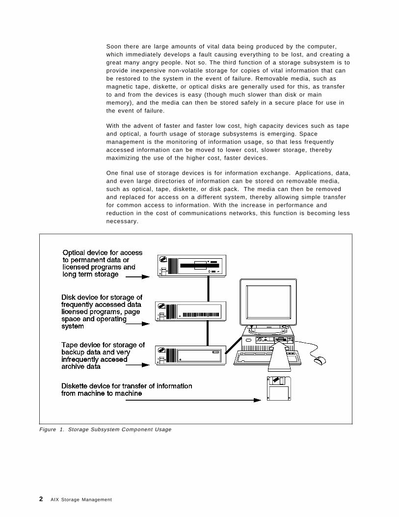
Soon there are large amounts of vital data being produced by the computer,which immediately develops a fault causing everything to be lost, and creating agreat many angry people. Not so. The third function of a storage subsystem is toprovide inexpensive non-volatile storage for copies of vital information that canbe restored to the system in the event of failure. Removable media, such asmagnetic tape, diskette, or optical disks are generally used for this, as transferto and from the devices is easy (though much slower than disk or mainmemory), and the media can then be stored safely in a secure place for use inthe event of failure.
With the advent of faster and faster low cost, high capacity devices such as tapeand optical, a fourth usage of storage subsystems is emerging. Spacemanagement is the monitoring of information usage, so that less frequentlyaccessed information can be moved to lower cost, slower storage, therebymaximizing the use of the higher cost, faster devices.
One final use of storage devices is for information exchange. Applications, data,and even large directories of information can be stored on removable media,such as optical, tape, diskette, or disk pack. The media can then be removedand replaced for access on a different system, thereby allowing simple transferfor common access to information. With the increase in performance andreduction in the cost of communications networks, this function is becoming lessnecessary.
Figure 1. Storage Subsystem Component Usage
2 AIX Storage Management
1.1.2 Hardware ConceptsAs has been described in the previous section, storage subsystems componentshave evolved to meet specific requirements within the computer system, andeach have different characteristics that enable these requirements to be met. Astorage subsystem may contain any or all of the following types of device.
1. Diskette Storage
Diskettes, or floppy disks, were among the first permanent storage devicesdeveloped. Information can be written to and read from a diskette via adiskette drive unit attached to the computer system. The diskette can then beremoved and reinserted into a drive on another computer, where theinformation can be utilized. Information can be accessed directly fromanywhere on the diskette so individual files can be quickly located andaccessed if required.
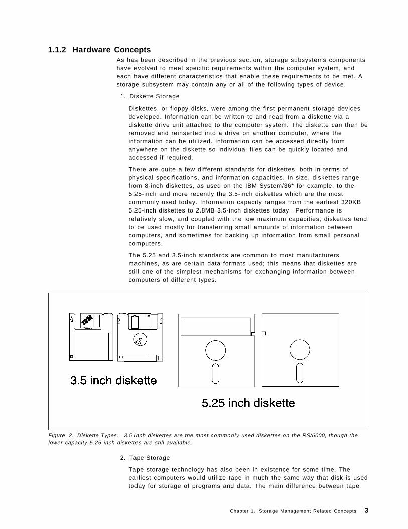
There are quite a few different standards for diskettes, both in terms ofphysical specifications, and information capacities. In size, diskettes rangefrom 8-inch diskettes, as used on the IBM System/36* for example, to the5.25-inch and more recently the 3.5-inch diskettes which are the mostcommonly used today. Information capacity ranges from the earliest 320KB5.25-inch diskettes to 2.8MB 3.5-inch diskettes today. Performance isrelatively slow, and coupled with the low maximum capacities, diskettes tendto be used mostly for transferring small amounts of information betweencomputers, and sometimes for backing up information from small personalcomputers.
The 5.25 and 3.5-inch standards are common to most manufacturersmachines, as are certain data formats used; this means that diskettes arestill one of the simplest mechanisms for exchanging information betweencomputers of different types.
Figure 2. Diskette Types. 3.5 inch diskettes are the most commonly used diskettes on the RS/6000, though thelower capacity 5.25 inch diskettes are still available.
2. Tape Storage
Tape storage technology has also been in existence for some time. Theearliest computers would utilize tape in much the same way that disk is usedtoday for storage of programs and data. The main difference between tape
Chapter 1. Storage Management Related Concepts 3
and other forms of storage device is that information is read and writtensequentially. This means that random access to information on a tape isslow, as the tape must be sequentially searched from the beginning. Theread/write speed can be very fast, and the information capacity very high -up to 10GB per tape - which means that tapes are currently best suited forbacking up large amounts of data, or for infrequent access to archivedinformation.
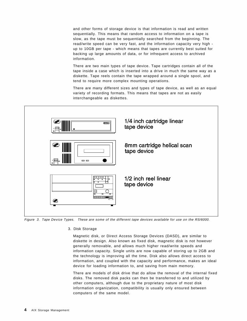
There are two main types of tape device. Tape cartridges contain all of thetape inside a case which is inserted into a drive in much the same way as adiskette. Tape reels contain the tape wrapped around a single spool, andtend to require more complex mounting operations.
There are many different sizes and types of tape device, as well as an equalvariety of recording formats. This means that tapes are not as easilyinterchangeable as diskettes.
Figure 3. Tape Device Types. These are some of the different tape devices available for use on the RS/6000.
3. Disk Storage
Magnetic disk, or Direct Access Storage Devices (DASD), are similar todiskette in design. Also known as fixed disk, magnetic disk is not howevergenerally removable, and allows much higher read/write speeds andinformation capacity. Single units are now capable of storing up to 2GB andthe technology is improving all the time. Disk also allows direct access toinformation, and coupled with the capacity and performance, makes an idealdevice for loading information to, and saving from main memory.
There are models of disk drive that do allow the removal of the internal fixeddisks. The removed disk packs can then be transferred to and utilized byother computers, although due to the proprietary nature of most diskinformation organization, compatibility is usually only ensured betweencomputers of the same model.
4 AIX Storage Management
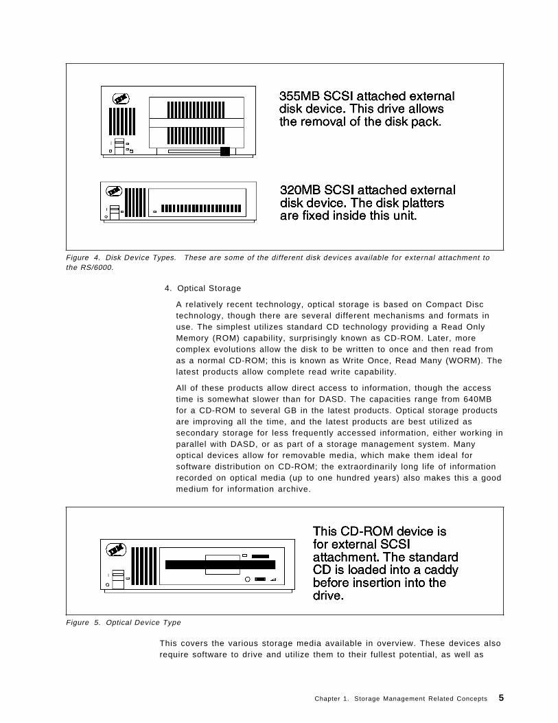
Figure 4. Disk Device Types. These are some of the different disk devices available for external attachment tothe RS/6000.
4. Optical Storage
A relatively recent technology, optical storage is based on Compact Disctechnology, though there are several different mechanisms and formats inuse. The simplest utilizes standard CD technology providing a Read OnlyMemory (ROM) capability, surprisingly known as CD-ROM. Later, morecomplex evolutions allow the disk to be written to once and then read fromas a normal CD-ROM; this is known as Write Once, Read Many (WORM). Thelatest products allow complete read write capability.
All of these products allow direct access to information, though the accesstime is somewhat slower than for DASD. The capacities range from 640MBfor a CD-ROM to several GB in the latest products. Optical storage productsare improving all the time, and the latest products are best utilized assecondary storage for less frequently accessed information, either working inparallel with DASD, or as part of a storage management system. Manyoptical devices allow for removable media, which make them ideal forsoftware distribution on CD-ROM; the extraordinarily long life of informationrecorded on optical media (up to one hundred years) also makes this a goodmedium for information archive.
Figure 5. Optical Device Type
This covers the various storage media available in overview. These devices alsorequire software to drive and utilize them to their fullest potential, as well as
Chapter 1. Storage Management Related Concepts 5
hardware attachment methods. Both these topics will be discussed later in thischapter.
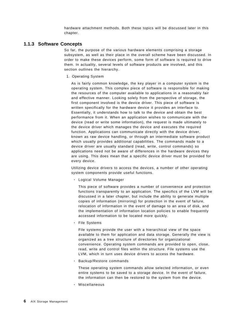
1.1.3 Software ConceptsSo far, the purpose of the various hardware elements comprising a storagesubsystem, as well as their place in the overall scheme have been discussed. Inorder to make these devices perform, some form of software is required to drivethem. In actuality, several levels of software products are involved, and thissection outlines the hierarchy.
1. Operating System
As is fairly common knowledge, the key player in a computer system is theoperating system. This complex piece of software is responsible for makingthe resources of the computer available to applications in a reasonably fairand effective manner. Looking solely from the perspective of storage, thefirst component involved is the device driver. This piece of software iswritten specifically for the hardware device it provides an interface to.Essentially, it understands how to talk to the device and obtain the bestperformance from it. When an application wishes to communicate with thedevice (read or write some information), the request is made ultimately tothe device driver which manages the device and executes the requiredfunction. Applications can communicate directly with the device driver,known as raw device handling, or through an intermediate software productwhich usually provides additional capabilities. The commands made to adevice driver are usually standard (read, write, control commands) soapplications need not be aware of differences in the hardware devices theyare using. This does mean that a specific device driver must be provided forevery device.
Utilizing device drivers to access the devices, a number of other operatingsystem components provide useful functions.
• Logical Volume Manager
This piece of software provides a number of convenience and protectionfunctions transparently to an application. The specifics of the LVM will bediscussed in a later chapter, but include the ability to generate multiplecopies of information (mirroring) for protection in the event of failure,relocation of information in the event of damage to an area of disk, andthe implementation of information location policies to enable frequentlyaccessed information to be located more quickly.
• File Systems
File systems provide the user with a hierarchical view of the spaceavailable to them for application and data storage. Generally the view isorganized as a tree structure of directories for organizationalconvenience. Operating system commands are provided to open, close,read, write and control files within the structure. File systems use theLVM, which in turn uses device drivers to access the hardware.
• Backup/Restore commands
These operating system commands allow selected information, or evenentire systems to be saved to a storage device. In the event of failure,the information can then be restored to the system from the device.
• Miscellaneous
6 AIX Storage Management
There are a number of operating system commands that allow readingand writing of information to a storage device. Some of these aredesigned for specific devices, others generic, but they all use devicedrivers to communicate with the device.
These components will be discussed in more detail in Chapter 3, “OperatingSystem Software Components” on page 47.
2. Higher Level Tools
Higher level tools are generally applications that are designed to providemore complex storage management functions such as scheduled backup offiles, disk space management, and data archive for example. These toolswill usually employ many of the operating system functions to provide amore convenient interface to managing storage, which means that some ofthe capabilities of these products can be achieved with a good knowledge ofthe lower level operating system functions. Although beyond the scope ofthis book, some of these tools will be discussed in outline in Appendix B,“Higher Level Storage Management Products” on page 337.
3. Applications
Most applications will require access to information as part of their function.Many of them will access files through the file systems mentioned earlier,thus gaining the benefits of the more complex functions provided by this partof the operating system. Some applications will use storage devices directlythrough device drivers, which while being more complex in implementation,allows a more flexible approach to the management of their information.Databases are typical examples of applications that access storage devicesin this way.
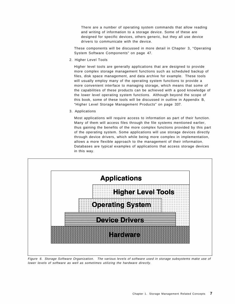
Figure 6. Storage Software Organization. The various levels of software used in storage subsystems make use oflower levels of software as well as sometimes utilizing the hardware directly.
Chapter 1. Storage Management Related Concepts 7
1.2 Storage ManagementSo far, the computing environment in general has been described in order toallow the storage elements of the system to be positioned and discussedgenerally. This section will focus on storage management; what are the issuesthat this area addresses, and what aspects of a storage subsystem does it focuson.
1.2.1 Hardware ManagementFrom the hardware point of view, all of the devices that can constitute a storagesubsystem have been briefly discussed, and will be explored in more detail inthe next chapter. The intention here is to look at what aspects of their operationare critical to overall system operation, and therefore form the focus of storagemanagement. This should put into context the discussion in later chapters of theoperating system commands and higher level tools available.
There are three main considerations, performance, availability, and capacity.
1.2.1.1 PerformancePerformance is usually all about providing access to a resource such thatparticular criteria are met. The resources in a storage subsystem all havedifferent characteristics and intended uses, and therefore the criteria applied arealso different. In general though, it is safe to say that performance in storageproducts is about maximizing the throughput of information to and from thedevice.
As has been said, there are different criteria for each device and some examplesfollow, though a more complete discussion of maximizing performance forstorage subsystems can be found in Chapter 5, “Storage Subsystem Design” onpage 79 and Chapter 6, “General AIX Storage Management” on page 95.
• System bus
All information passed to I/O devices must at some stage cross the systembus. The performance of this device is a common factor for all devices,though rarely a bottleneck.
• Hardware attachment adapter
The physical attachment of all I/O devices to the system is via some sort ofadapter. There are various types including SCSI, Serial, Optical, andChannel. Some of the issues which affect performance at the adapter are thedata rate, the number of devices supported, and the command capability ofthe adapter. For example, some adapters are capable of overlappingcommands, duplex communication, and sorting of requests for bestperformance.
• Disk Devices
Throughput to a disk depends on a number of things, the most basic of whichis the maximum read/write capability of the disk for sequential operations,which is fixed by the disk technology; the maximum possible data rate from asingle disk cannot be higher than this. The intended usage of the disk willalso affect performance. Random access requests, where the disk read/writehead has to move around the disk a great deal will take longer thansequential requests which involve only the initial search for the data. Thereare other facilities such as mirroring, where multiple copies of data aremaintained in parallel. This can provide higher throughput when access to
8 AIX Storage Management
the data occurs in parallel, as well as increased availability due to themultiple copies, though at the cost of increased disk space requirements.
The design of a storage subsystem will involve considering these optionsand more. As will be seen after the section on availability, many of thesepossibilities involve trade-offs with performance and cost, the final decisionoften being one of compromise. Actual subsystem design is covered in moredetail in Chapter 5, “Storage Subsystem Design” on page 79, and diskfunction in 2.2.2.1, “Disk Technology” on page 25.
• Tape Devices
Throughput to tape devices is also limited to the maximum read/writecapability of the drive. Tape devices access information sequentially by theirnature, information being read and written on a sequential medium. Assuch, random access to information is slow, and tape devices are notnormally called upon for this requirement. Some tape devices provide fordata compression when writing and decompression when reading, therebyincreasing the volume of data and therefore the throughput. Some tapesubsystems provide autochangers with access to a library of tapes; in theseinstances, tape selection and load time also become a throughput issue.
Performance in tape devices is therefore generally a straightforwardconsideration of the physical specifications: features provided (for examplecompression and libraries), throughput, and perhaps compatibility with othertape media. Again, these issues will be discussed in Chapter 5, “StorageSubsystem Design” on page 79. Tape function is covered in 2.2.3, “TapeStorage” on page 34.
• Optical Devices
Throughput to optical devices involves elements from both disk and tapedevices. Optical devices operate in a similar fashion to disks, allowingsequential and random access, and therefore present similar designconsiderations; optical devices do generally possess a lower data rate thanmagnetic disk though.
In common with tape devices, it is possible to have optical libraries whichagain present similar considerations to tape library access.
Performance of optical technology is also therefore dependent upon theintended environment, as well as the basic characteristics of the media.Design issues will be covered in more detail in Chapter 5, “StorageSubsystem Design” on page 79, and the technology itself is discussed in2.2.4, “Optical Storage” on page 40.
Chapter 1. Storage Management Related Concepts 9
Figure 7. Importance of Performance Management. Users can become a tri f le irr i table if information is notquickly forthcoming from their computer systems.
1.2.1.2 AvailabilityAvailability concerns designing the storage subsystem to minimize the effects offailure in any of the elements. Every environment will have differentrequirements in this area, but essentially the intention is to ensure the continuedoperation of the system despite failure in certain components. The level ofredundancy, or replication of devices for replacement purposes in the event offailure, is again a trade-off with price and performance.
• Tape Devices
As has been explained in the previous section on performance, tape devicesare generally used for backup/restore operations, which means that they donot tend to be a critical part of the subsystem (unless failure occurs duringrestore after a crash, or during usage of the device itself), and as such,having an alternative device to use may be sufficient for most situations.
• Optical Devices
Optical devices again do not tend to be used for primary data storage, due totheir slower access times, rather being used for archive or less frequentlyaccessed information. As such, providing a replacement device may also besufficient protection against failure. As with tape devices though, the exactrequirements will vary with the environment in question, and a morecomprehensive account of the design considerations can be found in thesection on storage subsystem design.
• Disk Devices
Disk devices constitute the most vital element of a storage subsystem,indeed of the computer system. Processors and memory can be replaced,but a disk crash can cause the loss of irreplaceable information.Furthermore, disk devices are in continuous use as extensions to mainmemory, and as storage for frequently accessed data; as such, availability ofthese devices is of prime concern.
10 AIX Storage Management
Availability in this context has several connotations. The first and mostobvious, relates to ensuring that required information is always available,and that corruption or problems with access to this data can becompensated for. Techniques for ensuring this include file journaling andmirroring, which are discussed in the section on file systems and AIX*Storage Management respectively. These techniques ensure access to datacan be maintained continuously, even in the event of a hardware disk failure.Generally, though, some time will need to be spent with the system notoperational to allow rebuilding of file systems, or replacement of damagedparts; this activity should of course be scheduled to minimize its impact, butis nevertheless a requirement.
The second connotation relates to not only ensuring that data is alwaysavailable, but that any repairs can be effected whilst the system remainsoperational. The main technique for ensuring this function, is utilizing someform of RAID (Redundant Array of Independent Disks). RAID is beyond thescope of this book, but basically involves providing an intelligent array ofdisks that allows mirroring, parallel access to data, on-line replacement offailing components, and high performance.
Figure 8. Importance of Availability. However careful ly managed a computer system is, there wi l l always beunforeseen circumstances when information is lost.
1.2.1.3 CapacityThe last main consideration is that of the capacity of the devices. Capacity isgenerally related to performance, the more space that a device has, the longerthe average access time will be. This tends to be more important for devices thatwill be used to access data for interactive use (such as disk or optical), and itcan sometimes be more prudent to utilize more lower capacity devices thanfewer larger capacity devices. This will be a trade-off between cost andperformance again, and there are other solutions to increasing performancethrough parallel access to devices.
In the main, increasing capacity with disk devices involves purchasing eitherlarger, or more devices. With optical and tape devices there is another option,
Chapter 1. Storage Management Related Concepts 11
and that is the library. Optical and tape libraries provide the capability to storemany tapes or optical cartridges within a managed library, such that when arequest for a particular piece of data arrives, the library knows which tape oroptical cartridge the information is on, and can then utilize robotics to select theitem and load it into the tape or optical device. Libraries are discussed in moredetail in 2.2.3.2, “Selecting the Correct Tape Storage Devices” on page 38 and2.2.4.2, “Selecting the Correct Optical Storage Devices” on page 43.
Thus the three major criteria from a hardware point of view, are the performanceof the storage subsystem, or more generally, it′s throughput, the maintenance ofthe required level of availability of the information stored, and the quantity ofdata that can be kept, or capacity.
1.2.2 Software ManagementFrom the point of view of software in storage management, the main elementshave been described in overview, and will be covered in detail in the section onOperating System Software Components. The intent of this section is to examinethe main issues that software management aims to address, in order to providea context for the discussion of the features currently available for storagemanagement, as well as the new features provided in AIX Version 4.
There are three considerations, space, recovery, and administration.
1.2.2.1 SpaceAs has been discussed, in any computer system, there is a finite amount of fastmain system memory. This, coupled with the requirement for non-volatilestorage, leads to the necessity for the provision of cheaper, auxiliary storage. Itis a truism to say that anything grows to fill the available resource, and this isparticularly true of information stored in computer systems; thus the cheaperdisk storage devices used for accessing frequently used data will also becomefull over time, particularly when availability designs are taken into account.Whilst cheap, disk devices are not that cheap, and so some sort of plan formanaging available disk space must be developed.
Managing disk space usually involves moving less frequently accessedinformation out to slower, larger capacity, and cheaper per unit of information,storage devices. Optical storage devices supporting read and write capability arean ideal medium for this less frequently accessed information. Optical storagecan be treated in the same way as disk, with only access time being slower.Using statistics on data access, less frequently used information can be movedto the optical media, the slightly longer delay in retrieval being acceptable forthis type of information.
There is also a large amount of information that is very infrequently, if ever,accessed; tax information must be kept for five years for example, in case aninspection is required. This kind of information can be moved to even slower,massive capacity devices, such as tape libraries.
Again, this process is a trade-off between space and access time, and is usuallycalled data archiving. Policies can be defined, and operating system tools usedto manage disk space, as will be shown in the chapters on operating systemsoftware. There are also higher level tools designed specifically to provideautomatic management, and some examples of these can be found inAppendix B, “Higher Level Storage Management Products” on page 337.
12 AIX Storage Management
Figure 9. Space Management. Organization of the available storage space on the computer system is veryimportant to ensure sufficient room for all of the currently required information, as well as projected growth.
1.2.2.2 RecoveryThe second consideration is concerned with making provisions for failures in thestorage subsystem. Disk devices can fail for a variety of reasons includingmechanical faults such as head crashes, electronic failures, and corrupted dataon the disk itself; optical storage can suffer from mechanical problems, tapedevices can fail, and information written to tape can be unreadable due toproblems with the tape media. Users of the system are also prone, on occasion,to accidentally erase vital components of the system, operating system files, ordata. There is also the possibility of natural disasters such as fires, floods, oreven lightning.
When a failure occurs, and it will, it would be fairly useful to be able to restorethe system to its state prior to the problem. This is what recovery managementis all about. There are several different strategies that can be employed, andthese will be discussed in detail in the chapters on storage management, but themain point is to ensure that a current copy of the information stored in thesystem is available to reload from. This copy is usually stored on tape, and itscurrency reflects the amount of data that an organization can afford to lose. Forexample, if losing more than a days worth of information would be fatal to acompany, then copies of at least the vital data need to be made daily. There arevarious ways to minimize the amount of information that needs to be copiedeach time, as well as high level tools to assist in managing the process. Some ofthe high level tools will be briefly discussed in Appendix B, “Higher LevelStorage Management Products” on page 337. Again, the operating systemprovides the basic tools to manage this process, and this area will be examinedin more detail in the chapters on storage management.
Chapter 1. Storage Management Related Concepts 13
Figure 10. Recovery Management. The effects of disaster can be minimized if sensible backup precautions havebeen taken. Having the right tools and procedures for the job eases the task of recovery.
1.2.2.3 AdministrationIn order to make use of the devices constituting a storage subsystem, theoperating system needs to made aware of them, their capabilities, and how theyare to be used. Furthermore, in the event of failure, or for general maintenance,there are tasks that need doing, such as making devices temporarily unavailableso that they can be replaced, or reconfigured. Additionally, performance andusage statistics may need to be gathered so that informed planning andmanagement can take place.
The operating system therefore provides administrative commands and toolsthat enable these processes to be performed. Devices can be defined to thesystem, made available or unavailable, configured, and monitored forperformance and usage. One other useful administrative tool gives the ability todefine and manage quotas for disk usage, thereby allowing a modicum of controlto be exercised over usage, and thereby ease the task of managing thesubsystem. These activities are examined in more detail in the chapters onoperating system software components and storage management.
Diskette devices have not been mentioned in this section on storagemanagement, mainly because their major usage is for simple transfer of smallamounts of information between computer systems that are not connected via anetwork. In the past, when the quantity of information stored on computers (andstill today for some smaller personal computers), diskette devices were used forbackup purposes. Whilst remaining very inexpensive per diskette, and althoughthe capacity has grown to several megabytes, the sheer volume of informationcontained in a general system backup precludes the use of diskettes for thispurpose.
14 AIX Storage Management
1.3 SummaryThis chapter has looked at the basic concepts of storage management.
The first section examined the rationale behind storage subsystems, explainingat a high level, the reasons why auxiliary storage is required. The componentsthat comprise storage subsystems:
• Diskette devices
• Tape devices
• Disk devices
• Optical devices
were looked at individually, and their basic capabilities discussed. Finally, thesoftware components used with storage subsystems were discussed:
• Logical Volume Manager
• File systems
• Device drivers
• Higher level tools
• Applications
again at a high level, in order to demonstrate the levels of function provided bythe various parts.
The second section looked at the rationale behind storage management. Theconsiderations involved in hardware management:
• Performance
• Availability
• Capacity
were discussed, along with an examination of the impact that particular deviceshave in these areas. The issues addressed by software management:
• Space
• Recovery
• Administration
were explained in overview to put into context discussion in later chapters ofthese processes, and the tools and commands that enable them.
Chapter 1. Storage Management Related Concepts 15

16 AIX Storage Management
Chapter 2. Hardware Storage Components
This chapter is intended to overview the capabilities and functions of thehardware storage devices available to AIX. This will help to provide a context forunderstanding more clearly the rationale behind some of the storagemanagement policies and the options and features of storage managementsoftware, as well as enabling more informed decisions to be made whenselecting hardware devices.
2.1 Selecting the Hardware ComponentsSelection of the components that will make up the storage subsystem rangesfrom very easy to being a complex trade-off. First of all, the applicationrequirements need to be considered in terms of their storage necessities, themix of storage device types then needs to be decided, and finally specificproducts need to be chosen.
2.1.1 Points to ConsiderSelecting the correct products for inclusion into a storage managementsubsystem involves consideration of a number of points:
• Cost per megabyte
The cost per megabyte of storing information on a device is alwaysimportant. This cost is usually proportional to the speed of access to data onthe device, and generally also proportional to the capacity. If rapid access todata is essential, then the cost will be higher.
• Access frequency
This figure represents the number of times data on the device will beaccessed in a given period. The higher this figure, the higher the data rate,access times, and reliability usually need to be. Devices supporting frequentaccess are usually required for interactive types of applications.
• Access density
This value describes the number of I/O requests per gigabyte of data. Thisvalue needs to be considered in conjunction with the access frequency. Highaccess density and low frequency suggests using optical storage; highdensity and high frequency suggests disk; low density and low frequencysuggests tape; low density and high frequency may involve other decisionpoints such as cost.
• Access type
This describes the required method for access to the data on the device, andcan be sequential or random. Random access means accessing smallamounts of data at many points on the device, whilst sequential accessmeans accessing large amounts of data from relatively few points. Thedifference is mainly to do with just how easy it is to locate specific dataelements on the device. If it takes a long time to search for the requiredinformation, then random access is not recommended. Databaseapplications tend to involve random requests, whilst backups or restoreswould be good examples of sequential operations.
• Data rate
Copyright IBM Corp. 1994 17
This describes how rapidly the data can be obtained from the device (oncelocated). Interactive applications tend to require a high data rate, whilstbatch applications can usually tolerate lower data rates.
• Online life
This describes how long data will need to be accessible on the device, andis sometimes known as data age. Data age is usually inversely proportionalto access frequency, and therefore high values here usually imply the use oflow cost, low speed, high capacity devices.
• Interchange requirements
Will the information stored on this device be exchanged with other systems?If this is the case, then some form of removable media will be required.
• Longevity
If archive, backup or even reference information is to be stored for longperiods of time, then the integrity of the media used is important. Mostmedia have a shelf life, after which degradation of stored information islikely.
• Reliability
This is an extremely important consideration, particularly when missioncritical information is being considered.
• Regulatory requirements
Some industries are under legal restrictions with regard to datamanagement. Restrictions can apply, among other things, to access securityand length of time that records must be retained for.
2.1.2 How to Make the DecisionThe decision as to which storage device is best for a given environment can berepresented using a Venn diagram as in Figure 11 on page 19.
2.1.2.1 The Simple CaseThis example shows the case where the decision is not complicated;examination of the points discussed in 2.1.1, “Points to Consider” on page 17has placed the solution completely into one of the shaded areas:
• Disk
Disk would be selected when the environment requires high performanceand response times are critical.
• Tape
Tape would be the choice where low cost archive of information, high speedsequential access to data, and/or backup/interchange of data is required.
• Optical
Optical should be used if long term archive of information is the primaryrequirement.
18 AIX Storage Management
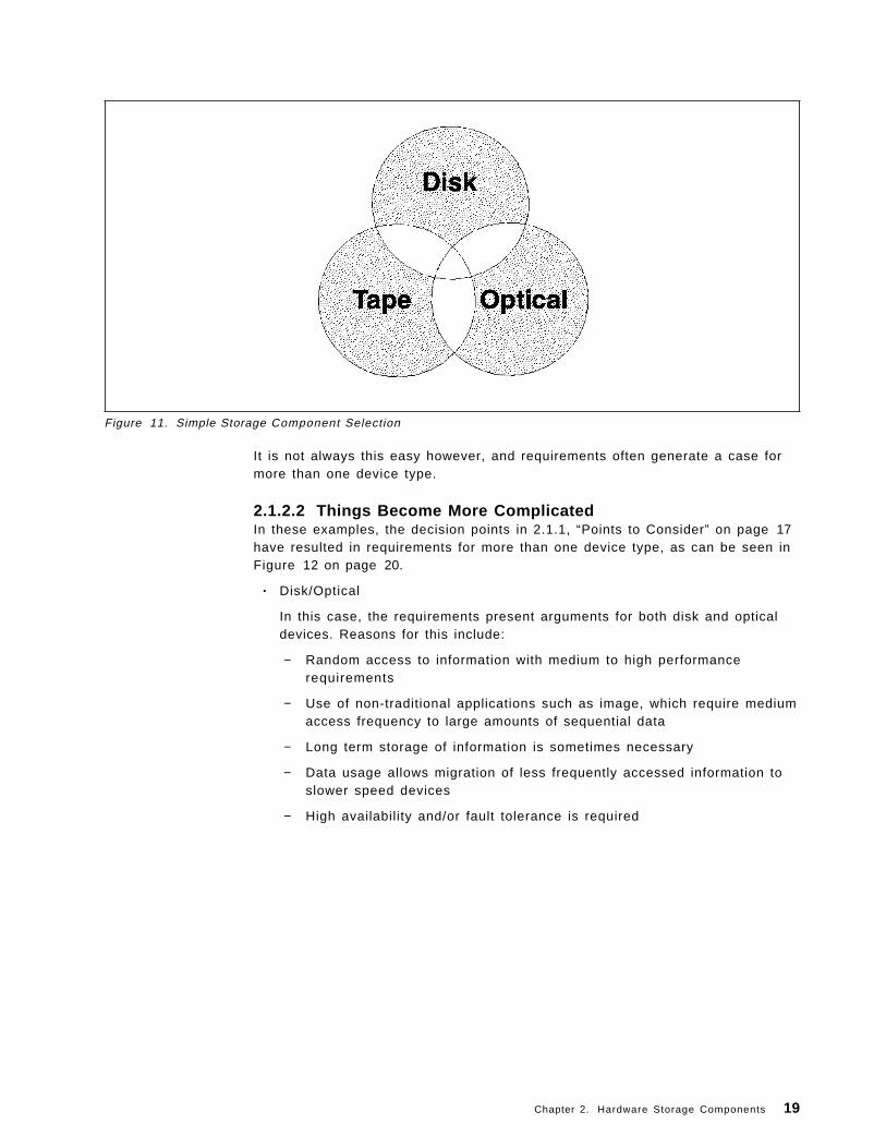
Figure 11. Simple Storage Component Selection
It is not always this easy however, and requirements often generate a case formore than one device type.
2.1.2.2 Things Become More ComplicatedIn these examples, the decision points in 2.1.1, “Points to Consider” on page 17have resulted in requirements for more than one device type, as can be seen inFigure 12 on page 20.
• Disk/Optical
In this case, the requirements present arguments for both disk and opticaldevices. Reasons for this include:
− Random access to information with medium to high performancerequirements
− Use of non-traditional applications such as image, which require mediumaccess frequency to large amounts of sequential data
− Long term storage of information is sometimes necessary
− Data usage allows migration of less frequently accessed information toslower speed devices
− High availability and/or fault tolerance is required
Chapter 2. Hardware Storage Components 19
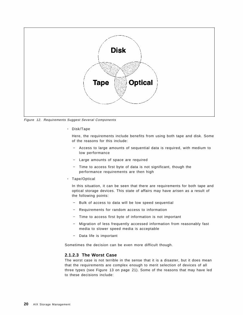
Figure 12. Requirements Suggest Several Components
• Disk/Tape
Here, the requirements include benefits from using both tape and disk. Someof the reasons for this include:
− Access to large amounts of sequential data is required, with medium tolow performance
− Large amounts of space are required
− Time to access first byte of data is not significant, though theperformance requirements are then high
• Tape/Optical
In this situation, it can be seen that there are requirements for both tape andoptical storage devices. This state of affairs may have arisen as a result ofthe following points:
− Bulk of access to data will be low speed sequential
− Requirements for random access to information
− Time to access first byte of information is not important
− Migration of less frequently accessed information from reasonably fastmedia to slower speed media is acceptable
− Data life is important
Sometimes the decision can be even more difficult though.
2.1.2.3 The Worst CaseThe worst case is not terrible in the sense that it is a disaster, but it does meanthat the requirements are complex enough to merit selection of devices of allthree types (see Figure 13 on page 21). Some of the reasons that may have ledto these decisions include:
20 AIX Storage Management
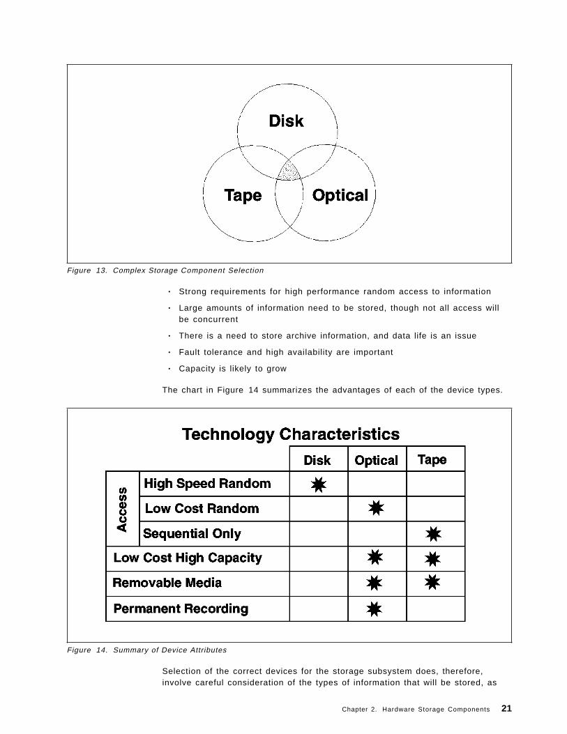
Figure 13. Complex Storage Component Selection
• Strong requirements for high performance random access to information
• Large amounts of information need to be stored, though not all access willbe concurrent
• There is a need to store archive information, and data life is an issue
• Fault tolerance and high availability are important
• Capacity is likely to grow
The chart in Figure 14 summarizes the advantages of each of the device types.
Figure 14. Summary of Device Attributes
Selection of the correct devices for the storage subsystem does, therefore,involve careful consideration of the types of information that will be stored, as
Chapter 2. Hardware Storage Components 21
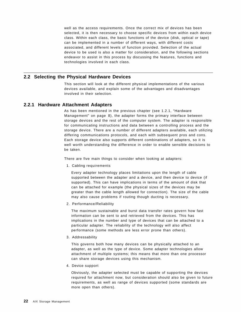
well as the access requirements. Once the correct mix of devices has beenselected, it is then necessary to choose specific devices from within each deviceclass. Within each class, the basic functions of the device (disk, optical or tape)can be implemented in a number of different ways, with different costsassociated, and different levels of function provided. Selection of the actualdevice to be used is also a matter for consideration, and the following sectionsendeavor to assist in this process by discussing the features, functions andtechnologies involved in each class.
2.2 Selecting the Physical Hardware DevicesThis section will look at the different physical implementations of the variousdevices available, and explain some of the advantages and disadvantagesinvolved in their selection.
2.2.1 Hardware Attachment AdaptersAs has been mentioned in the previous chapter (see 1.2.1, “HardwareManagement” on page 8), the adapter forms the primary interface betweenstorage devices and the rest of the computer system. The adapter is responsiblefor communicating instructions and data between a controlling process and thestorage device. There are a number of different adapters available, each utilizingdiffering communications protocols, and each with subsequent pros and cons.Each storage device also supports different combinations of adapters, so it iswell worth understanding the difference in order to enable sensible decisions tobe taken.
There are five main things to consider when looking at adapters:
1. Cabling requirements
Every adapter technology places limitations upon the length of cablesupported between the adapter and a device, and then device to device (ifsupported). This can have implications in terms of the amount of disk thatcan be attached for example (the physical sizes of the devices may begreater than the cable length allowed for connection). The size of the cablemay also cause problems if routing though ducting is necessary.
2. Performance/Reliability
The maximum sustainable and burst data transfer rates govern how fastinformation can be sent to and retrieved from the devices. This hasimplications in the number and type of devices that can be attached to aparticular adapter. The reliability of the technology will also affectperformance (some methods are less error prone than others).
3. Addressability
This governs both how many devices can be physically attached to anadapter, as well as the type of device. Some adapter technologies allowattachment of multiple systems; this means that more than one processorcan share storage devices using this mechanism.
4. Device support
Obviously, the adapter selected must be capable of supporting the devicesrequired for attachment now, but consideration should also be given to futurerequirements, as well as range of devices supported (some standards aremore open than others).
22 AIX Storage Management
5. Cost
Both the cost of the adapter and the average cost of devices supportingattachment to the adapter should be considered. Some technologies aremore expensive than others.
The following sections look at the various adapter options available.
2.2.1.1 Small Computer System Interface AdapterThe Small Computer System Interface or SCSI is one of the most commonmechanisms for attaching both IBM* and non-IBM peripherals. SCSI originatedfrom the selector channel on IBM System/360* computers, and was later scaleddown by the Shutgart Associates Company to make a universal, intelligent diskdrive interface. After around four years of discussions, in 1986, SCSI became anANSI standard, expanded to support other kinds of devices as well.
This standard, now referred to as SCSI-1, allows a maximum of seven devices tobe attached, and provides a one byte wide parallel bus. Each attached devicehas a unique address to allow the operating system to communicate with it. Datacan be transmitted either synchronously, or asynchronously, depending upon thecapabilities of the device used; both asynchronous and synchronous devices canshare the same SCSI bus, and in fact, all devices must start up in asynchronousmode initially to enable this compatibility. Asynchronous transfer rates aretypically around 1 to 2.5MB per second, while synchronous devices cancommunicate faster, from 4 to 10MB per second. This original standard definedoptional synchronous clock speed of up to 5MHz, giving a maximum data rate of5MB per second on the one byte wide bus.
With the release of the SCSI-1 standard in 1986, work started on a new standard,predictably called SCSI-2. This standard is still in the process of being officiallyapproved as an ANSI standard, though many vendors, including IBM, haveimplemented most of the features in the draft standard. Among the new featuresare the following improvements.
• Command Tag Queuing
This provides the ability to queue multiple commands to devicesunderstanding the SCSI-2 protocol, which improves performance by makingmore efficient use of the available bandwidth.
• Fast SCSI
The standard now defines permissible clock speeds of from 5 to 10MHz,which increases the data rate to 10MB per second on a one byte wide bus.
• Wide SCSI
The standard now also allows bus widths of up to four bytes, though inpractice, physical design limitations have meant that two byte wide busesare generally used. With 10MHz clock speeds, a two byte wide bus givesburst data rates of 20MB per second.
Downward compatibility is maintained so that SCSI-1 devices can be attached toSCSI-2 buses. SCSI-1 will be used when communicating with these devices, andSCSI-2 to devices on the same bus supporting the new functions.
There are two alternative electrical configurations possible for the SCSI-1 andSCSI-2 standards.
1. Single Ended
Chapter 2. Hardware Storage Components 23
The single ended interface comprises a ground and single signal line foreach of the SCSI data and control functions. This is the simplestconfiguration possible, but is prone to electrical interference, and thereforehas recommended cable lengths of from three to six meters.
2. Differential
The differential interface comprises positive and negative signal lines foreach of the data and control functions. The binary value of the transmittedsignal is determined from the difference between the voltages of these twosignals. Interference will affect both signals equally, hence not changing thedifference between them; this provides for far more reliable communication,with correspondingly greater cable lengths of up to 19 meters allowed.
There is a third SCSI standard currently being discussed, not surprisingly knownas SCSI-3. This standard will provide for even higher data rates, larger numbersof addresses, and greater cable lengths between devices. This will be possiblethrough the utilization of serial buses and packetized protocols. New media willbe supported, such as fiber optics, twisted pair, or even wireless.
SCSI also supports the attachment of multiple processors to the SCSI bus, whichallows implementation of device sharing.
2.2.1.2 High Performance Disk Drive Subsystem AdapterThe High Performance Disk Drive Subsystem adapter provides for attachment ofup to four serially attached disk subsystems, each of which may address up tofour disk devices, giving a total addressability of 16 devices. The distancesbetween adapter and subsystem can be up to 10 meters using copper twistedpair cables. The serial link uses full duplex packetized communications to thedisk subsystems, and can support a maximum total data transfer rate of 80MBper second.
2.2.1.3 High Performance Parallel Interface AdapterThe High Performance Parallel Interface (HiPPI) adapter provides an ANSIstandard parallel interface to other computers and to storage devices. Theadapter provides simplex or duplex point to point communication at burst datarates of up to 800Mb per second (in each direction) over copper cable atdistances of up to 25 meters. This cable distance can be extended using fiberoptic extenders or OEM HiPPI switches. The adapter consists of three cards onthe RS/6000*, requiring five slots for power consumption reasons; only one isinstallable per Micro Channel* bus. These points limit the environments that theHiPPI interface can be used in as they restrict the possible configurations of thesystem.
2.2.1.4 ESCON Channel AdapterThe ESCON channel adapter supports the transfer of data between an RS/6000and the ESCON channel at a maximum rate of 17MB per second. The adaptersupports connections over fiber optic links using LED or LASER technologies.The link between control units, directors and systems can be up to threekilometers with LED technology, and up to 20 kilometers using LASER.
24 AIX Storage Management
2.2.1.5 System/370 Channel Emulator AdapterThe System/370 channel emulator adapter provides parallel channel attachmentcapability via the block multiplexor channel, and supports data transfer at ratesof up to 4.5MB per second. The block multiplexor channel cable length can be upto 61 meters in length, and up to four control units can be supported.
2.2.1.6 Serial Storage ArchitectureSerial Storage Architecture, or SSA, is an emerging standard defining a newconnection mechanism for peripheral devices. The architecture specifies a serialinterface that has the benefits of more compact cables and connectors, higherperformance and reliability, and ultimately, a lower subsystem cost. A generalpurpose transport layer provides for 20MB per second full duplexcommunications over 10 meter copper cables. Devices are connected together instrings, with up to 128 nodes (devices) allowed per string. Information istransmitted in 128 byte frames that are multiplexed to allow concurrentoperations. In addition, the full duplex communications allows simultaneousreading and writing of data.
2.2.1.7 Other AdaptersThere are a number of devices that can be connected via local area networks. Inthe main, these devices support some form of networking protocol, such asTCP/IP and NFS, that allow the computer system to access the device as thoughit were local. In these cases, the computer system would be attached to the LANusing a token ring or Ethernet adapter.
2.2.2 Disk StorageThis section will look at disk technology generally, before going on to examinethe decision process necessary to select the correct disk subsystems for theenvironment.
2.2.2.1 Disk TechnologyAll disk devices are constructed in basically the same way (see Figure 15 onpage 26). A number of disk platters fixed to a central hub are rotated at highspeed by a motor. Both surfaces of each platter are coated with a thin film ofmagnetic material where the data will be stored. Information is written to andread from the magnetic surface via small read and write heads that are locatedat the end of mechanical arms known as actuators The actuators move theheads back and forth from the outer edge of the platters to the inner edge. Datais written to the disk surface in concentric tracks , so the movement of theactuator locates the head over the required track, and the rotation of the plattermoves the track past the heads allowing information to be read or written. Eachplatter surface has read and write heads associated with it, though all heads areusually attached to the same actuator assembly, moving in concert, with dataread from one platter surface and one track at a time. The length of time it takesfor the actuator to move the head to the required track is known as the seektime, while the time taken for the rotation of the platter to bring the correct partof the track under the heads is known as the rotational latency. Once correctlypositioned, data is read or written in a continuous stream, and the rate at whichthis occurs is called the data transfer rate. The combination of the averages ofseek time, rotational latency, and data transfer rate define the performance ofthe disk device.
Chapter 2. Hardware Storage Components 25
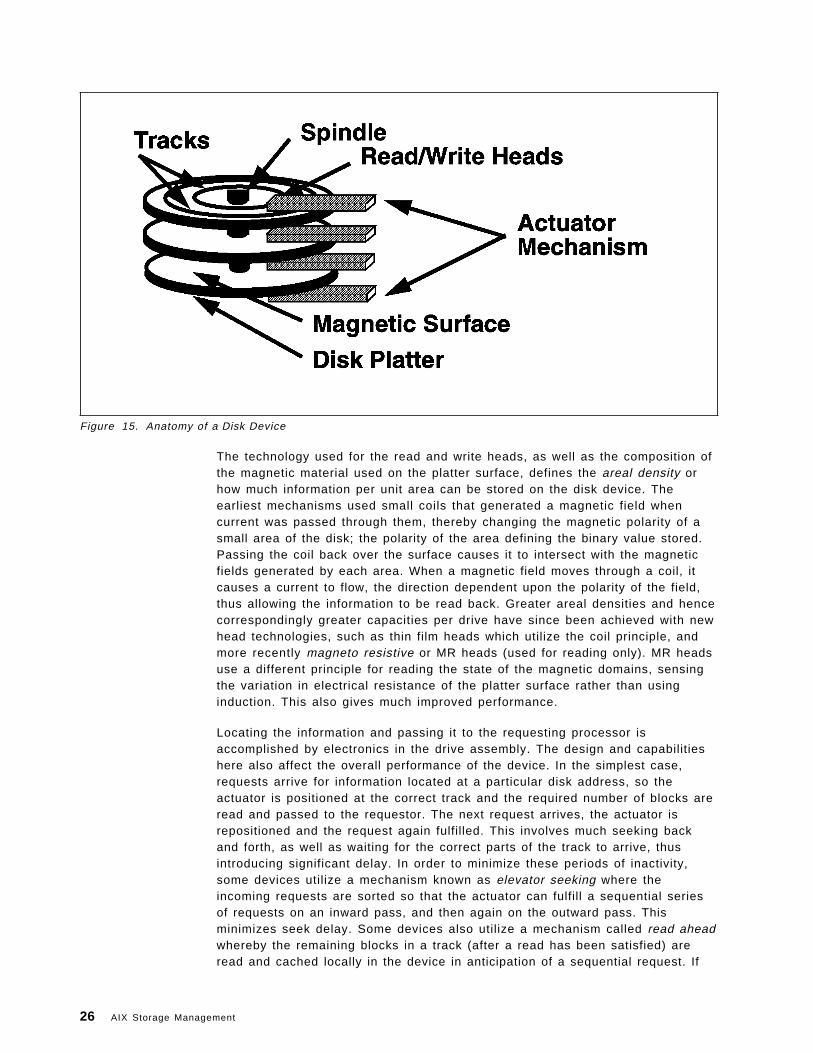
Figure 15. Anatomy of a Disk Device
The technology used for the read and write heads, as well as the composition ofthe magnetic material used on the platter surface, defines the areal density orhow much information per unit area can be stored on the disk device. Theearliest mechanisms used small coils that generated a magnetic field whencurrent was passed through them, thereby changing the magnetic polarity of asmall area of the disk; the polarity of the area defining the binary value stored.Passing the coil back over the surface causes it to intersect with the magneticfields generated by each area. When a magnetic field moves through a coil, itcauses a current to flow, the direction dependent upon the polarity of the field,thus allowing the information to be read back. Greater areal densities and hencecorrespondingly greater capacities per drive have since been achieved with newhead technologies, such as thin film heads which utilize the coil principle, andmore recently magneto resistive or MR heads (used for reading only). MR headsuse a different principle for reading the state of the magnetic domains, sensingthe variation in electrical resistance of the platter surface rather than usinginduction. This also gives much improved performance.
Locating the information and passing it to the requesting processor isaccomplished by electronics in the drive assembly. The design and capabilitieshere also affect the overall performance of the device. In the simplest case,requests arrive for information located at a particular disk address, so theactuator is positioned at the correct track and the required number of blocks areread and passed to the requestor. The next request arrives, the actuator isrepositioned and the request again fulfilled. This involves much seeking backand forth, as well as waiting for the correct parts of the track to arrive, thusintroducing significant delay. In order to minimize these periods of inactivity,some devices utilize a mechanism known as elevator seeking where theincoming requests are sorted so that the actuator can fulfill a sequential seriesof requests on an inward pass, and then again on the outward pass. Thisminimizes seek delay. Some devices also utilize a mechanism called read aheadwhereby the remaining blocks in a track (after a read has been satisfied) areread and cached locally in the device in anticipation of a sequential request. If
26 AIX Storage Management
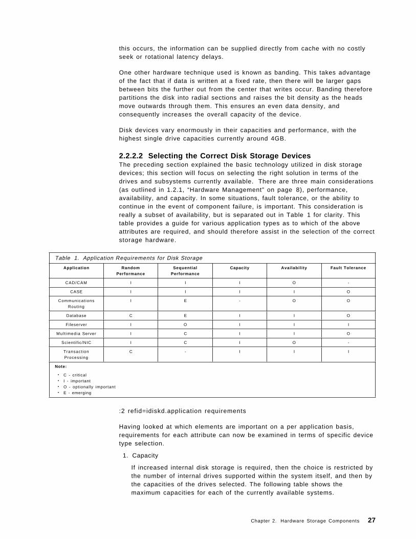
this occurs, the information can be supplied directly from cache with no costlyseek or rotational latency delays.
One other hardware technique used is known as banding. This takes advantageof the fact that if data is written at a fixed rate, then there will be larger gapsbetween bits the further out from the center that writes occur. Banding thereforepartitions the disk into radial sections and raises the bit density as the headsmove outwards through them. This ensures an even data density, andconsequently increases the overall capacity of the device.
Disk devices vary enormously in their capacities and performance, with thehighest single drive capacities currently around 4GB.
2.2.2.2 Selecting the Correct Disk Storage DevicesThe preceding section explained the basic technology utilized in disk storagedevices; this section will focus on selecting the right solution in terms of thedrives and subsystems currently available. There are three main considerations(as outlined in 1.2.1, “Hardware Management” on page 8), performance,availability, and capacity. In some situations, fault tolerance, or the ability tocontinue in the event of component failure, is important. This consideration isreally a subset of availability, but is separated out in Table 1 for clarity. Thistable provides a guide for various application types as to which of the aboveattributes are required, and should therefore assist in the selection of the correctstorage hardware.
Table 1. Application Requirements for Disk Storage
Application RandomPerformance
SequentialPerformance
Capacity Avai labi l i ty Fault Tolerance
CAD/CAM I I I O -
CASE I I I I O
Communicat ions
Routing
I E - O O
Database C E I I O
Fileserver I O I I I
Mul t imedia Server I C I I O
Scient i f ic/NIC I C I O -
Transact ion
Processing
C - I I I
Note:
• C - crit ical• I - important• O - optionally important• E - emerging
:2 refid=idiskd.application requirements
Having looked at which elements are important on a per application basis,requirements for each attribute can now be examined in terms of specific devicetype selection.
1. Capacity
If increased internal disk storage is required, then the choice is restricted bythe number of internal drives supported within the system itself, and then bythe capacities of the drives selected. The following table shows themaximum capacities for each of the currently available systems.
Chapter 2. Hardware Storage Components 27
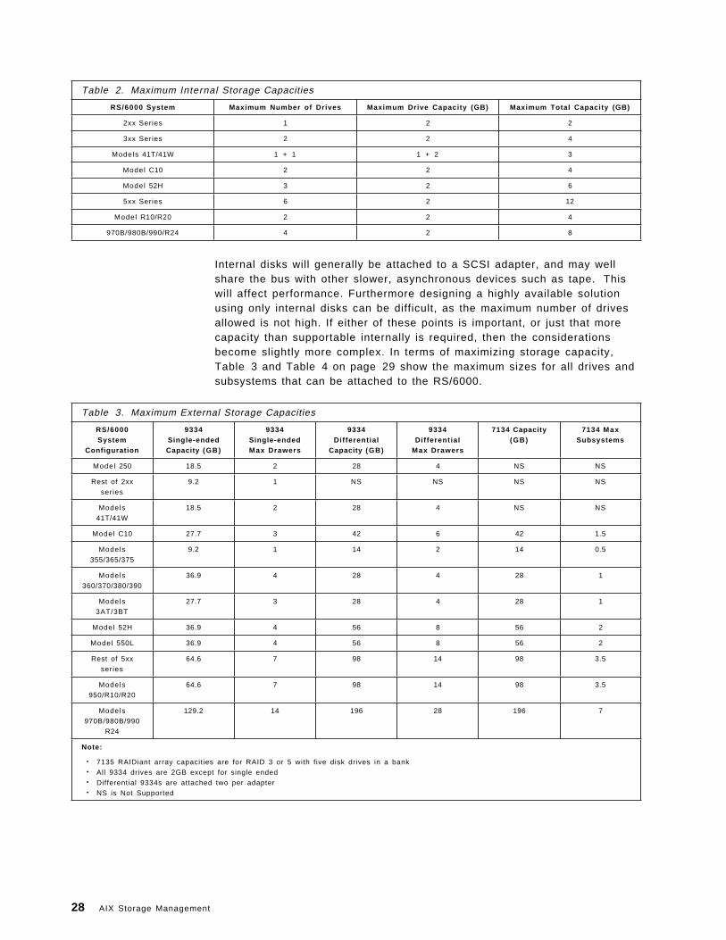
Table 2. Maximum Internal Storage Capacities
RS/6000 System Maximum Number of Drives Maximum Drive Capacity (GB) Maximum Total Capacity (GB)
2xx Series 1 2 2
3xx Series 2 2 4
Models 41T/41W 1 + 1 1 + 2 3
Model C10 2 2 4
Model 52H 3 2 6
5xx Series 6 2 12
Model R10/R20 2 2 4
970B/980B/990/R24 4 2 8
Internal disks will generally be attached to a SCSI adapter, and may wellshare the bus with other slower, asynchronous devices such as tape. Thiswill affect performance. Furthermore designing a highly available solutionusing only internal disks can be difficult, as the maximum number of drivesallowed is not high. If either of these points is important, or just that morecapacity than supportable internally is required, then the considerationsbecome slightly more complex. In terms of maximizing storage capacity,Table 3 and Table 4 on page 29 show the maximum sizes for all drives andsubsystems that can be attached to the RS/6000.
Table 3. Maximum External Storage Capacities
RS/6000System
Configuration
9334Single-endedCapacity (GB)
9334Single-endedMax Drawers
9334Dif ferent ial
Capacity (GB)
9334Dif ferent ial
Max Drawers
7134 Capacity(GB)
7134 MaxSubsystems
Model 250 18.5 2 28 4 NS NS
Rest of 2xx
series
9.2 1 NS NS NS NS
Models
41T/41W
18.5 2 28 4 NS NS
Model C10 27.7 3 42 6 42 1.5
Models
355/365/375
9.2 1 14 2 14 0.5
Models
360/370/380/390
36.9 4 28 4 28 1
Models
3AT/3BT
27.7 3 28 4 28 1
Model 52H 36.9 4 56 8 56 2
Model 550L 36.9 4 56 8 56 2
Rest of 5xx
series
64.6 7 98 14 98 3.5
Models
950/R10/R20
64.6 7 98 14 98 3.5
Models
970B/980B/990
R24
129.2 14 196 28 196 7
Note:
• 7135 RAIDiant array capacities are for RAID 3 or 5 with five disk drives in a bank• All 9334 drives are 2GB except for single ended• Differential 9334s are attached two per adapter• NS is Not Supported
28 AIX Storage Management
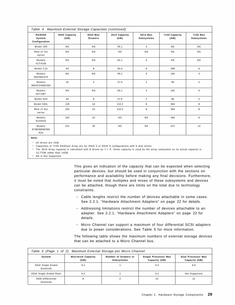
Table 4. Maximum External Storage Capacities (continued)
RS/6000System
Configuration
9333 Capacity(GB)
9333 MaxDrawers
3514 Capacity(GB)
3514 MaxSubsystems
7135 Capacity(GB)
7135 MaxSubsystems
Model 250 NS NS 55.1 4 NS NS
Rest of 2xx
series
NS NS NS NS NS NS
Models
41T/41W
NS NS 55.1 4 NS NS
Model C10 64 8 82.6 6 288 6
Models
355/365/375
NS NS 55.1 4 192 4
Models
360/370/380/390
32 4 27.5 2 96 2
Models
3AT/3BT
NS NS 55.1 4 192 4
Model 52H 64 8 27.5 2 96 2
Model 550L 128 16 110.2 8 384 8
Rest of 5xx
series
192 24 110.2 8 384 8
Models
R10/R20
192 24 NS NS 384 8
Models
970B/980B/990
R24
224 28 NS NS 672 14
Note:
• All drives are 2GB• Capacities of 7135 RAIDiant Array are for RAID 3 or RAID 5 configurations with 5 disk drives• The 3514 Array capacity is calculated with 8 drives as 7 + P. Some capacity is used by the array subsystem so its actual capacity is
13.77GB rather than 14GB.• NS is Not Supported
This gives an indication of the capacity that can be expected when selectingparticular devices, but should be used in conjunction with the sections onperformance and availability before making any final decisions. Furthermore,it must be noted that multiples and mixes of these subsystems and devicescan be attached, though there are limits on the total due to technologyconstraints.
• Cable lengths restrict the number of devices attachable in some cases.See 2.2.1, “Hardware Attachment Adapters” on page 22 for details.
• Addressing limitations restrict the number of devices attachable to anadapter. See 2.2.1, “Hardware Attachment Adapters” on page 22 fordetails.
• Micro Channel can support a maximum of four differential SCSI adaptersdue to power considerations. See Table 5 for more information.
The following table shows the maximum numbers of external storage devicesthat can be attached to a Micro Channel bus.
Table 5 (Page 1 of 2). Maximum External Storage per Micro Channel
System Max imum Capacity(GB)
Number of Drawers orSubsystems
Single Processor MaxCapacity (GB)
Dual Processor MaxCapacity (GB)
9334 Single Ended
Deskside
9.2 1 9.2 8.8
9334 Single Ended Rack 9.2 1 9.2 Not Supported
9334 Differential
Deskside
8 2 14 12
Chapter 2. Hardware Storage Components 29
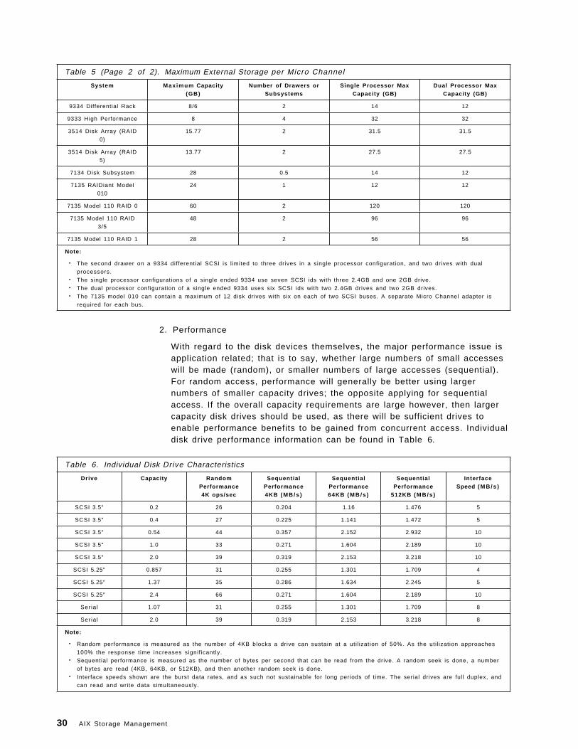
Table 5 (Page 2 of 2). Maximum External Storage per Micro Channel
System Max imum Capacity(GB)
Number of Drawers orSubsystems
Single Processor MaxCapacity (GB)
Dual Processor MaxCapacity (GB)
9334 Differential Rack 8/6 2 14 12
9333 High Performance 8 4 32 32
3514 Disk Array (RAID
0)
15.77 2 31.5 31.5
3514 Disk Array (RAID
5)
13.77 2 27.5 27.5
7134 Disk Subsystem 28 0.5 14 12
7135 RAIDiant Model
010
24 1 12 12
7135 Model 110 RAID 0 60 2 120 120
7135 Model 110 RAID
3/5
48 2 96 96
7135 Model 110 RAID 1 28 2 56 56
Note:
• The second drawer on a 9334 differential SCSI is l imited to three drives in a single processor configuration, and two drives with dual
processors.• The single processor configurations of a single ended 9334 use seven SCSI ids with three 2.4GB and one 2GB drive.• The dual processor configuration of a single ended 9334 uses six SCSI ids with two 2.4GB drives and two 2GB drives.• The 7135 model 010 can contain a maximum of 12 disk drives with six on each of two SCSI buses. A separate Micro Channel adapter is
required for each bus.
2. Performance
With regard to the disk devices themselves, the major performance issue isapplication related; that is to say, whether large numbers of small accesseswill be made (random), or smaller numbers of large accesses (sequential).For random access, performance will generally be better using largernumbers of smaller capacity drives; the opposite applying for sequentialaccess. If the overall capacity requirements are large however, then largercapacity disk drives should be used, as there will be sufficient drives toenable performance benefits to be gained from concurrent access. Individualdisk drive performance information can be found in Table 6.
Table 6. Individual Disk Drive Characteristics
Drive Capacity RandomPerformance4K ops/sec
SequentialPerformance4KB ( M B / s )
SequentialPerformance64KB ( M B / s )
SequentialPerformance
512KB ( M B / s )
InterfaceSpeed ( M B / s )
SCSI 3.5″ 0.2 26 0.204 1.16 1.476 5
SCSI 3.5″ 0.4 27 0.225 1.141 1.472 5
SCSI 3.5″ 0.54 44 0.357 2.152 2.932 10
SCSI 3.5″ 1.0 33 0.271 1.604 2.189 10
SCSI 3.5″ 2.0 39 0.319 2.153 3.218 10
SCSI 5.25″ 0.857 31 0.255 1.301 1.709 4
SCSI 5.25″ 1.37 35 0.286 1.634 2.245 5
SCSI 5.25″ 2.4 66 0.271 1.604 2.189 10
Serial 1.07 31 0.255 1.301 1.709 8
Serial 2.0 39 0.319 2.153 3.218 8
Note:
• Random performance is measured as the number of 4KB blocks a drive can sustain at a uti l ization of 50%. As the uti l ization approaches
100% the response time increases signif icantly.• Sequential performance is measured as the number of bytes per second that can be read from the drive. A random seek is done, a number
of bytes are read (4KB, 64KB, or 512KB), and then another random seek is done.• Interface speeds shown are the burst data rates, and as such not sustainable for long periods of time. The serial drives are full duplex, and
can read and write data simultaneously.
30 AIX Storage Management
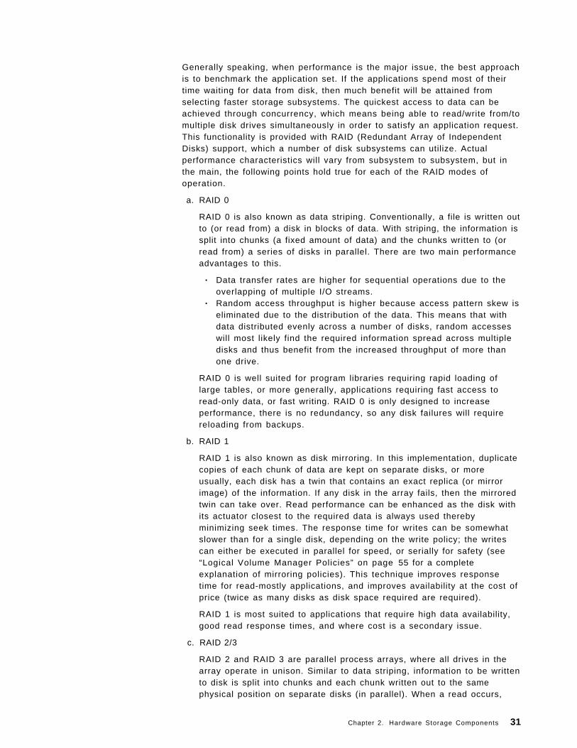
Generally speaking, when performance is the major issue, the best approachis to benchmark the application set. If the applications spend most of theirtime waiting for data from disk, then much benefit will be attained fromselecting faster storage subsystems. The quickest access to data can beachieved through concurrency, which means being able to read/write from/tomultiple disk drives simultaneously in order to satisfy an application request.This functionality is provided with RAID (Redundant Array of IndependentDisks) support, which a number of disk subsystems can utilize. Actualperformance characteristics will vary from subsystem to subsystem, but inthe main, the following points hold true for each of the RAID modes ofoperation.
a. RAID 0
RAID 0 is also known as data striping. Conventionally, a file is written outto (or read from) a disk in blocks of data. With striping, the information issplit into chunks (a fixed amount of data) and the chunks written to (orread from) a series of disks in parallel. There are two main performanceadvantages to this.
• Data transfer rates are higher for sequential operations due to theoverlapping of multiple I/O streams.
• Random access throughput is higher because access pattern skew iseliminated due to the distribution of the data. This means that withdata distributed evenly across a number of disks, random accesseswill most likely find the required information spread across multipledisks and thus benefit from the increased throughput of more thanone drive.
RAID 0 is well suited for program libraries requiring rapid loading oflarge tables, or more generally, applications requiring fast access toread-only data, or fast writing. RAID 0 is only designed to increaseperformance, there is no redundancy, so any disk failures will requirereloading from backups.
b. RAID 1
RAID 1 is also known as disk mirroring. In this implementation, duplicatecopies of each chunk of data are kept on separate disks, or moreusually, each disk has a twin that contains an exact replica (or mirrorimage) of the information. If any disk in the array fails, then the mirroredtwin can take over. Read performance can be enhanced as the disk withits actuator closest to the required data is always used therebyminimizing seek times. The response time for writes can be somewhatslower than for a single disk, depending on the write policy; the writescan either be executed in parallel for speed, or serially for safety (see“Logical Volume Manager Policies” on page 55 for a completeexplanation of mirroring policies). This technique improves responsetime for read-mostly applications, and improves availability at the cost ofprice (twice as many disks as disk space required are required).
RAID 1 is most suited to applications that require high data availability,good read response times, and where cost is a secondary issue.
c. RAID 2/3
RAID 2 and RAID 3 are parallel process arrays, where all drives in thearray operate in unison. Similar to data striping, information to be writtento disk is split into chunks and each chunk written out to the samephysical position on separate disks (in parallel). When a read occurs,
Chapter 2. Hardware Storage Components 31
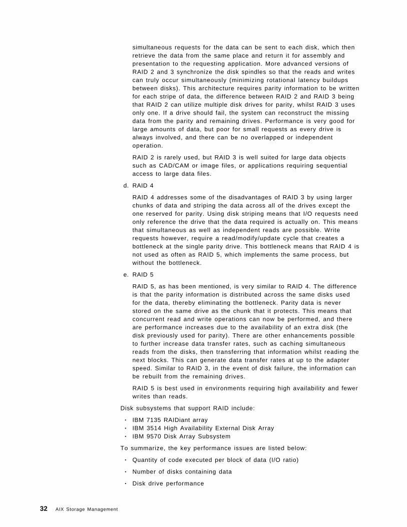
simultaneous requests for the data can be sent to each disk, which thenretrieve the data from the same place and return it for assembly andpresentation to the requesting application. More advanced versions ofRAID 2 and 3 synchronize the disk spindles so that the reads and writescan truly occur simultaneously (minimizing rotational latency buildupsbetween disks). This architecture requires parity information to be writtenfor each stripe of data, the difference between RAID 2 and RAID 3 beingthat RAID 2 can utilize multiple disk drives for parity, whilst RAID 3 usesonly one. If a drive should fail, the system can reconstruct the missingdata from the parity and remaining drives. Performance is very good forlarge amounts of data, but poor for small requests as every drive isalways involved, and there can be no overlapped or independentoperation.
RAID 2 is rarely used, but RAID 3 is well suited for large data objectssuch as CAD/CAM or image files, or applications requiring sequentialaccess to large data files.
d. RAID 4
RAID 4 addresses some of the disadvantages of RAID 3 by using largerchunks of data and striping the data across all of the drives except theone reserved for parity. Using disk striping means that I/O requests needonly reference the drive that the data required is actually on. This meansthat simultaneous as well as independent reads are possible. Writerequests however, require a read/modify/update cycle that creates abottleneck at the single parity drive. This bottleneck means that RAID 4 isnot used as often as RAID 5, which implements the same process, butwithout the bottleneck.
e. RAID 5
RAID 5, as has been mentioned, is very similar to RAID 4. The differenceis that the parity information is distributed across the same disks usedfor the data, thereby eliminating the bottleneck. Parity data is neverstored on the same drive as the chunk that it protects. This means thatconcurrent read and write operations can now be performed, and thereare performance increases due to the availability of an extra disk (thedisk previously used for parity). There are other enhancements possibleto further increase data transfer rates, such as caching simultaneousreads from the disks, then transferring that information whilst reading thenext blocks. This can generate data transfer rates at up to the adapterspeed. Similar to RAID 3, in the event of disk failure, the information canbe rebuilt from the remaining drives.
RAID 5 is best used in environments requiring high availability and fewerwrites than reads.
Disk subsystems that support RAID include:
• IBM 7135 RAIDiant array• IBM 3514 High Availability External Disk Array• IBM 9570 Disk Array Subsystem
To summarize, the key performance issues are listed below:
• Quantity of code executed per block of data (I/O ratio)
• Number of disks containing data
• Disk drive performance
32 AIX Storage Management
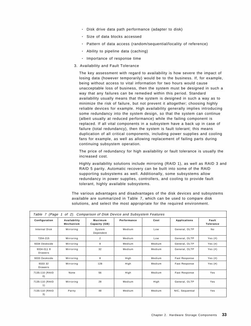
• Disk drive data path performance (adapter to disk)
• Size of data blocks accessed
• Pattern of data access (random/sequential/locality of reference)
• Ability to pipeline data (caching)
• Importance of response time
3. Availability and Fault Tolerance
The key assessment with regard to availability is how severe the impact oflosing data (however temporarily) would be to the business. If, for example,being without access to vital information for two hours would causeunacceptable loss of business, then the system must be designed in such away that any failures can be remedied within this period. Standardavailability usually means that the system is designed in such a way as tominimize the risk of failure, but not prevent it altogether; choosing highlyreliable devices for example. High availability generally implies introducingsome redundancy into the system design, so that the system can continue(albeit usually at reduced performance) while the failing component isreplaced. If all vital components in a subsystem have a back up in case offailure (total redundancy), then the system is fault tolerant; this meansduplication of all critical components, including power supplies and coolingfans for example, as well as allowing replacement of failing parts duringcontinuing subsystem operation.
The price of redundancy for high availability or fault tolerance is usually theincreased cost.
Highly availability solutions include mirroring (RAID 1), as well as RAID 3 andRAID 5 parity. Automatic recovery can be built into some of the RAIDsupporting subsystems as well. Additionally, some subsystems allowredundancy in power supplies, controllers, and cooling to provide faulttolerant, highly available subsystems.
The various advantages and disadvantages of the disk devices and subsystemsavailable are summarized in Table 7, which can be used to compare disksolutions, and select the most appropriate for the required environment.
Table 7 (Page 1 of 2). Comparison of Disk Device and Subsystem Features
Configuration Avai labi l i tyMechanism
Max imumCapacity (GB)
Performance Cost Applications FaultTolerance
Internal Disk Mi r ror ing System
Dependent
Medium Low General, OLTP No
7204-215 Mir ror ing 2 Medium Low General, OLTP Yes (#)
9334 Deskside Mi r ror ing 8 Medium Medium General, OLTP Yes (#)
9334-011 8
Drawers
Mi r ror ing 32 Medium Medium General, OLTP Yes (#)
9333 Deskside Mi r ror ing 8 High Medium Fast Response Yes (#)
9333 32
Drawers
Mi r ror ing 128 High Medium Fast Response Yes (#)
7135-110 (RAID
0)
None 56 High Medium Fast Response Yes
7135-110 (RAID
1)
Mi r ror ing 28 Medium High General, OLTP Yes
7135-110 (RAID
3)
Pari ty 48 Medium Medium NIC, Sequential Yes
Chapter 2. Hardware Storage Components 33
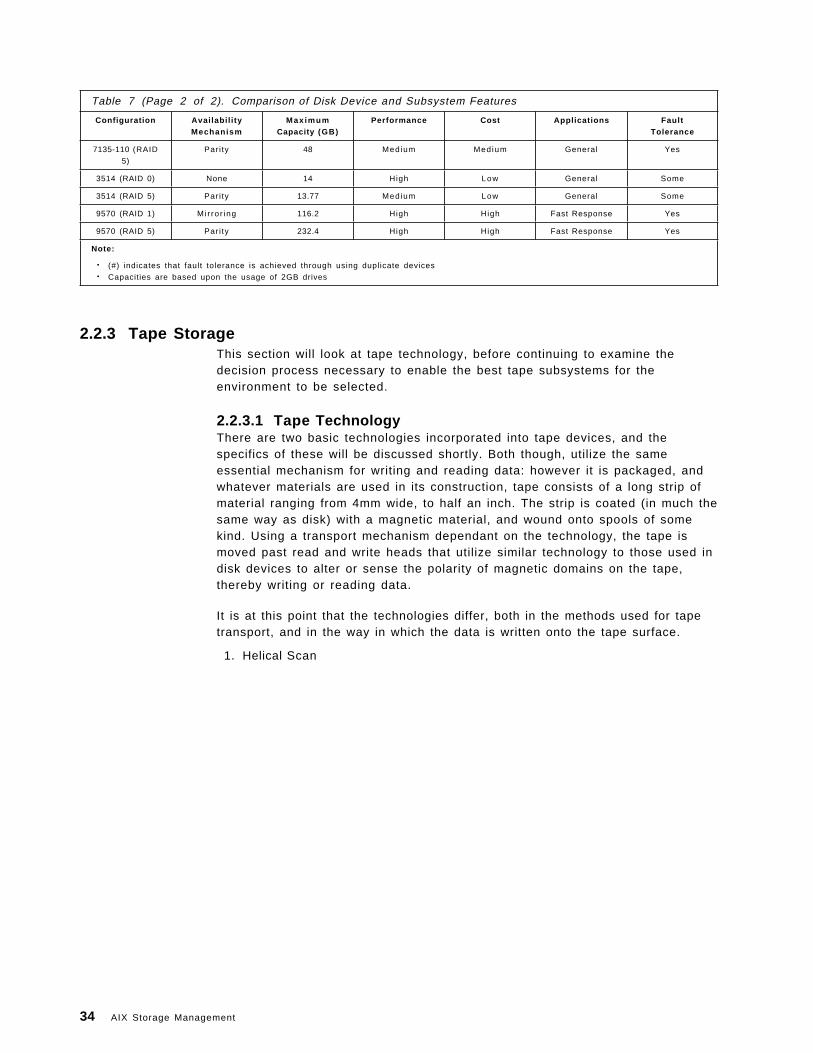
Table 7 (Page 2 of 2). Comparison of Disk Device and Subsystem Features
Configuration Avai labi l i tyMechanism
Max imumCapacity (GB)
Performance Cost Applications FaultTolerance
7135-110 (RAID
5)
Pari ty 48 Medium Medium General Yes
3514 (RAID 0) None 14 High Low General Some
3514 (RAID 5) Pari ty 13.77 Medium Low General Some
9570 (RAID 1) Mi r ror ing 116.2 High High Fast Response Yes
9570 (RAID 5) Pari ty 232.4 High High Fast Response Yes
Note:
• (#) indicates that fault tolerance is achieved through using duplicate devices• Capacities are based upon the usage of 2GB drives
2.2.3 Tape StorageThis section will look at tape technology, before continuing to examine thedecision process necessary to enable the best tape subsystems for theenvironment to be selected.
2.2.3.1 Tape TechnologyThere are two basic technologies incorporated into tape devices, and thespecifics of these will be discussed shortly. Both though, utilize the sameessential mechanism for writing and reading data: however it is packaged, andwhatever materials are used in its construction, tape consists of a long strip ofmaterial ranging from 4mm wide, to half an inch. The strip is coated (in much thesame way as disk) with a magnetic material, and wound onto spools of somekind. Using a transport mechanism dependant on the technology, the tape ismoved past read and write heads that utilize similar technology to those used indisk devices to alter or sense the polarity of magnetic domains on the tape,thereby writing or reading data.
It is at this point that the technologies differ, both in the methods used for tapetransport, and in the way in which the data is written onto the tape surface.
1. Helical Scan
34 AIX Storage Management
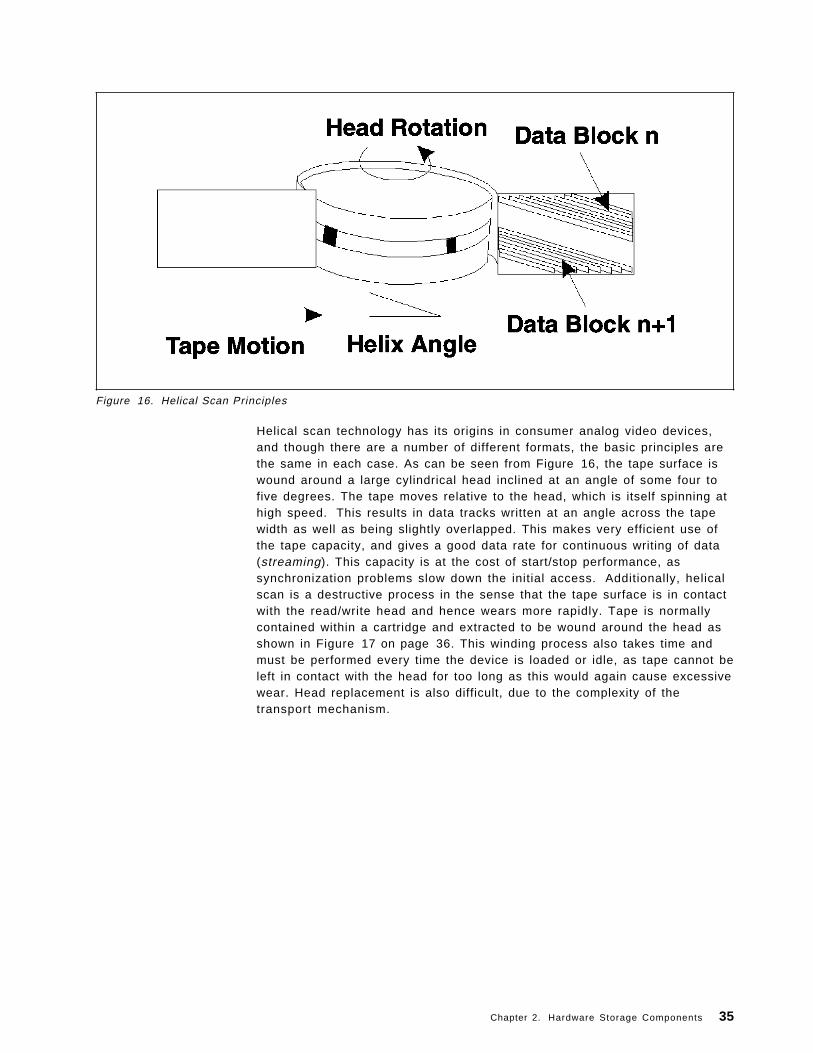
Figure 16. Helical Scan Principles
Helical scan technology has its origins in consumer analog video devices,and though there are a number of different formats, the basic principles arethe same in each case. As can be seen from Figure 16, the tape surface iswound around a large cylindrical head inclined at an angle of some four tofive degrees. The tape moves relative to the head, which is itself spinning athigh speed. This results in data tracks written at an angle across the tapewidth as well as being slightly overlapped. This makes very efficient use ofthe tape capacity, and gives a good data rate for continuous writing of data(streaming). This capacity is at the cost of start/stop performance, assynchronization problems slow down the initial access. Additionally, helicalscan is a destructive process in the sense that the tape surface is in contactwith the read/write head and hence wears more rapidly. Tape is normallycontained within a cartridge and extracted to be wound around the head asshown in Figure 17 on page 36. This winding process also takes time andmust be performed every time the device is loaded or idle, as tape cannot beleft in contact with the head for too long as this would again cause excessivewear. Head replacement is also difficult, due to the complexity of thetransport mechanism.
Chapter 2. Hardware Storage Components 35
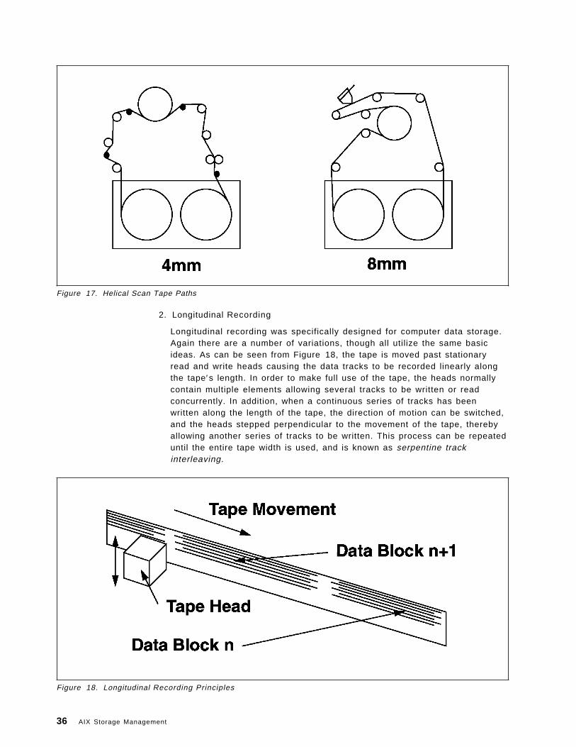
Figure 17. Helical Scan Tape Paths
2. Longitudinal Recording
Longitudinal recording was specifically designed for computer data storage.Again there are a number of variations, though all utilize the same basicideas. As can be seen from Figure 18, the tape is moved past stationaryread and write heads causing the data tracks to be recorded linearly alongthe tape′s length. In order to make full use of the tape, the heads normallycontain multiple elements allowing several tracks to be written or readconcurrently. In addition, when a continuous series of tracks has beenwritten along the length of the tape, the direction of motion can be switched,and the heads stepped perpendicular to the movement of the tape, therebyallowing another series of tracks to be written. This process can be repeateduntil the entire tape width is used, and is known as serpentine trackinterleaving.
Figure 18. Longitudinal Recording Principles
36 AIX Storage Management
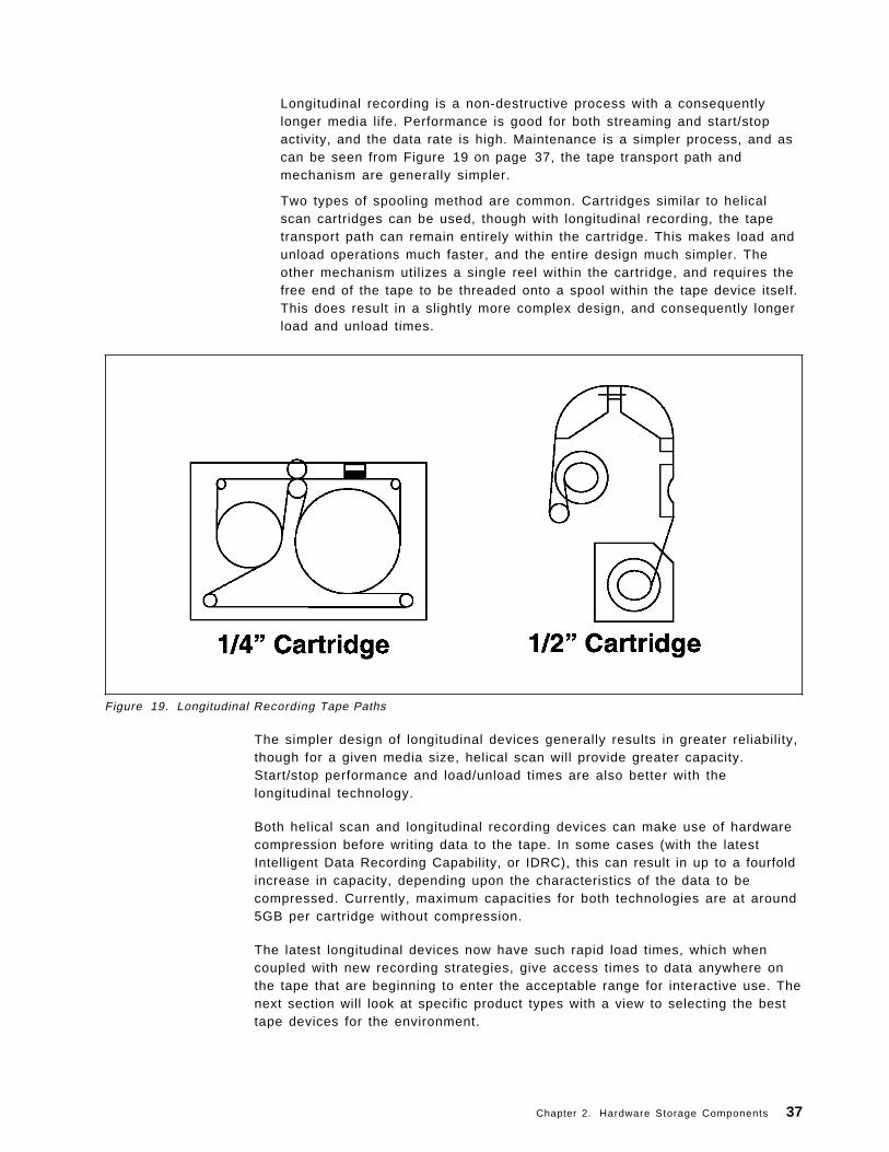
Longitudinal recording is a non-destructive process with a consequentlylonger media life. Performance is good for both streaming and start/stopactivity, and the data rate is high. Maintenance is a simpler process, and ascan be seen from Figure 19 on page 37, the tape transport path andmechanism are generally simpler.
Two types of spooling method are common. Cartridges similar to helicalscan cartridges can be used, though with longitudinal recording, the tapetransport path can remain entirely within the cartridge. This makes load andunload operations much faster, and the entire design much simpler. Theother mechanism utilizes a single reel within the cartridge, and requires thefree end of the tape to be threaded onto a spool within the tape device itself.This does result in a slightly more complex design, and consequently longerload and unload times.
Figure 19. Longitudinal Recording Tape Paths
The simpler design of longitudinal devices generally results in greater reliability,though for a given media size, helical scan will provide greater capacity.Start/stop performance and load/unload times are also better with thelongitudinal technology.
Both helical scan and longitudinal recording devices can make use of hardwarecompression before writing data to the tape. In some cases (with the latestIntelligent Data Recording Capability, or IDRC), this can result in up to a fourfoldincrease in capacity, depending upon the characteristics of the data to becompressed. Currently, maximum capacities for both technologies are at around5GB per cartridge without compression.
The latest longitudinal devices now have such rapid load times, which whencoupled with new recording strategies, give access times to data anywhere onthe tape that are beginning to enter the acceptable range for interactive use. Thenext section will look at specific product types with a view to selecting the besttape devices for the environment.
Chapter 2. Hardware Storage Components 37
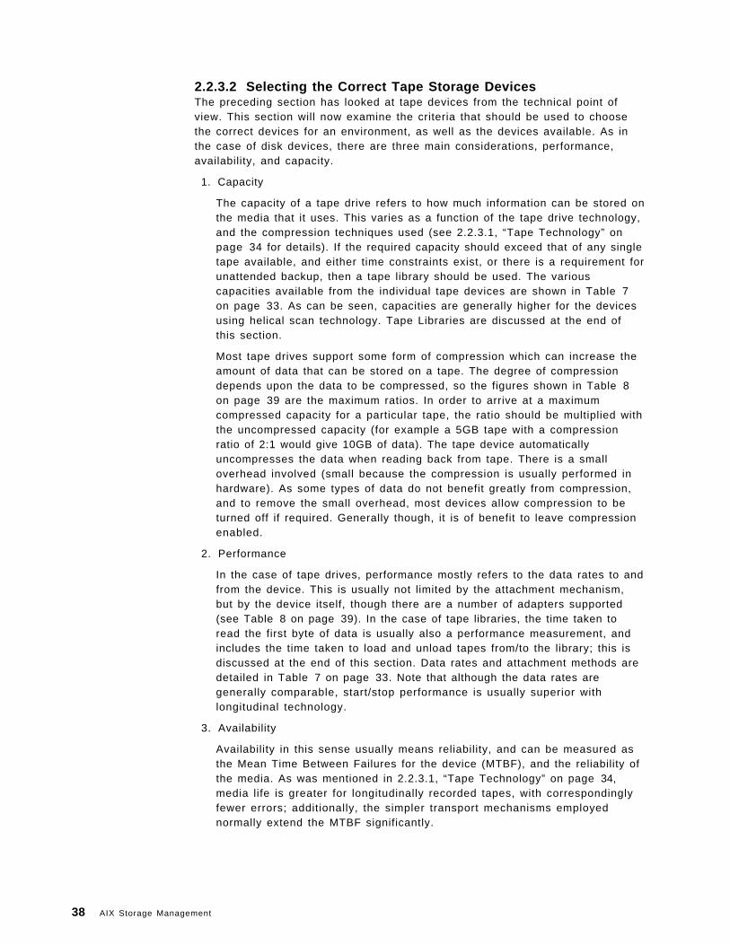
2.2.3.2 Selecting the Correct Tape Storage DevicesThe preceding section has looked at tape devices from the technical point ofview. This section will now examine the criteria that should be used to choosethe correct devices for an environment, as well as the devices available. As inthe case of disk devices, there are three main considerations, performance,availability, and capacity.
1. Capacity
The capacity of a tape drive refers to how much information can be stored onthe media that it uses. This varies as a function of the tape drive technology,and the compression techniques used (see 2.2.3.1, “Tape Technology” onpage 34 for details). If the required capacity should exceed that of any singletape available, and either time constraints exist, or there is a requirement forunattended backup, then a tape library should be used. The variouscapacities available from the individual tape devices are shown in Table 7on page 33. As can be seen, capacities are generally higher for the devicesusing helical scan technology. Tape Libraries are discussed at the end ofthis section.
Most tape drives support some form of compression which can increase theamount of data that can be stored on a tape. The degree of compressiondepends upon the data to be compressed, so the figures shown in Table 8on page 39 are the maximum ratios. In order to arrive at a maximumcompressed capacity for a particular tape, the ratio should be multiplied withthe uncompressed capacity (for example a 5GB tape with a compressionratio of 2:1 would give 10GB of data). The tape device automaticallyuncompresses the data when reading back from tape. There is a smalloverhead involved (small because the compression is usually performed inhardware). As some types of data do not benefit greatly from compression,and to remove the small overhead, most devices allow compression to beturned off if required. Generally though, it is of benefit to leave compressionenabled.
2. Performance
In the case of tape drives, performance mostly refers to the data rates to andfrom the device. This is usually not limited by the attachment mechanism,but by the device itself, though there are a number of adapters supported(see Table 8 on page 39). In the case of tape libraries, the time taken toread the first byte of data is usually also a performance measurement, andincludes the time taken to load and unload tapes from/to the library; this isdiscussed at the end of this section. Data rates and attachment methods aredetailed in Table 7 on page 33. Note that although the data rates aregenerally comparable, start/stop performance is usually superior withlongitudinal technology.
3. Availability
Availability in this sense usually means reliability, and can be measured asthe Mean Time Between Failures for the device (MTBF), and the reliability ofthe media. As was mentioned in 2.2.3.1, “Tape Technology” on page 34,media life is greater for longitudinally recorded tapes, with correspondinglyfewer errors; additionally, the simpler transport mechanisms employednormally extend the MTBF significantly.
38 AIX Storage Management
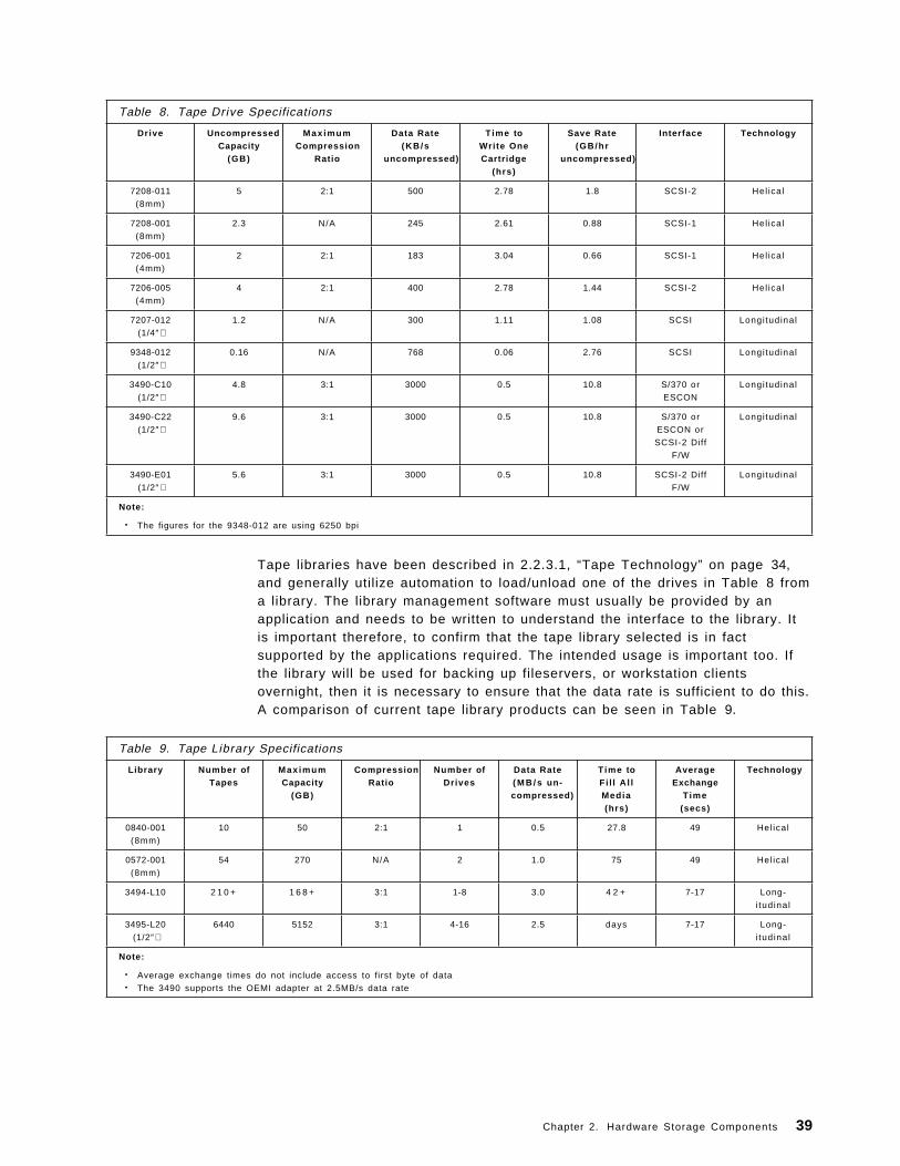
Table 8. Tape Drive Specifications
Drive UncompressedCapacity
(GB)
Max imumCompression
Ratio
Data Rate(KB/s
uncompressed)
T ime toWri te OneCartridge
(hrs)
Save Rate(GB/hr
uncompressed)
Interface Technology
7208-011
(8mm)
5 2:1 500 2.78 1.8 SCSI-2 Hel ical
7208-001
(8mm)
2.3 N/A 245 2.61 0.88 SCSI-1 Hel ical
7206-001
(4mm)
2 2:1 183 3.04 0.66 SCSI-1 Hel ical
7206-005
(4mm)
4 2:1 400 2.78 1.44 SCSI-2 Hel ical
7207-012
(1/4″)1.2 N/A 300 1.11 1.08 SCSI Longi tudinal
9348-012
(1/2″)0.16 N/A 768 0.06 2.76 SCSI Longi tudinal
3490-C10
(1/2″)4.8 3:1 3000 0.5 10.8 S/370 or
ESCON
Longitudinal
3490-C22
(1/2″)9.6 3:1 3000 0.5 10.8 S/370 or
ESCON or
SCSI-2 Diff
F/W
Longi tudinal
3490-E01
(1/2″)5.6 3:1 3000 0.5 10.8 SCSI-2 Diff
F/W
Longi tudinal
Note:
• The figures for the 9348-012 are using 6250 bpi
Tape libraries have been described in 2.2.3.1, “Tape Technology” on page 34,and generally utilize automation to load/unload one of the drives in Table 8 froma library. The library management software must usually be provided by anapplication and needs to be written to understand the interface to the library. Itis important therefore, to confirm that the tape library selected is in factsupported by the applications required. The intended usage is important too. Ifthe library will be used for backing up fileservers, or workstation clientsovernight, then it is necessary to ensure that the data rate is sufficient to do this.A comparison of current tape library products can be seen in Table 9.
Table 9. Tape Library Specifications
Library Number ofTapes
Max imumCapacity
(GB)
CompressionRatio
Number ofDrives
Data Rate( M B / s un-compressed)
T ime toFi l l A l lMedia(hrs)
AverageExchange
Time(secs)
Technology
0840-001
(8mm)
10 50 2:1 1 0.5 27.8 49 Hel ical
0572-001
(8mm)
54 270 N/A 2 1.0 75 49 Hel ical
3494-L10 2 1 0 + 1 6 8 + 3:1 1-8 3.0 4 2 + 7-17 Long-
i tudinal
3495-L20
(1/2″)6440 5152 3:1 4-16 2.5 days 7-17 Long-
i tudinal
Note:
• Average exchange times do not include access to first byte of data• The 3490 supports the OEMI adapter at 2.5MB/s data rate
Chapter 2. Hardware Storage Components 39
2.2.4 Optical StorageThis section will look at optical storage technology, before going on to examinethe decision process required to choose the right optical storage devices for theenvironment.
2.2.4.1 Optical TechnologyThere are three basic optical technologies, each providing for differentcapabilities. Some devices will cope with more than one kind of technology,though this is not always so. In all three cases, information is stored in tracks onthe media surface. Each mechanism then uses different methods to read andwrite information on these tracks.
1. Compact Disk Read Only Memory
With Compact Disk Read Only Memory, or CD-ROM, information is moldedinto the media during the manufacturing process as a series of pits in thesurface. The existence or absence of a pit determines the binary state ateach point. The information is read back by shining a laser onto the disksurface and measuring the reflected intensity. The compact disk is spun athigh speed inside the device and the laser assembly moved radially in andout to give access to the required blocks of information. CD-ROMs arecheap to make and provide an excellent distribution medium. The onlypotential issue is that there is no recording capability.
2. Rewritable
Rewritable media uses magneto-optic technology to store information. Ascan be seen from Figure 20 on page 41, the media surface is comprised ofconcentric tracks of magnetic material. With this technique, the read/writehead consists of two components, an electromagnet and a laser. The mediais first prepared by heating each magnetic domain with a high powered laserin the presence of a magnetic field. This causes the domains to adopt acommon polarity. Writing is accomplished by again heating up a domain withthe laser while applying a magnetic field of reverse polarity to flip its state.Reading back information is achieved using the reflected light from a lowerpowered laser to detect the original polarity domains (zeros) and thereversed polarity domains (ones), through a polarization effect. Erasing isimplemented by again heating up the domains with a high powered laserand simultaneously using the electromagnet to reset the polarity to itsoriginal state.
While providing the benefits of read, write and erase, this technology stillmanages to be very stable, giving a shelf life of around 10,000 years, andarchival life of around 150 years.
40 AIX Storage Management
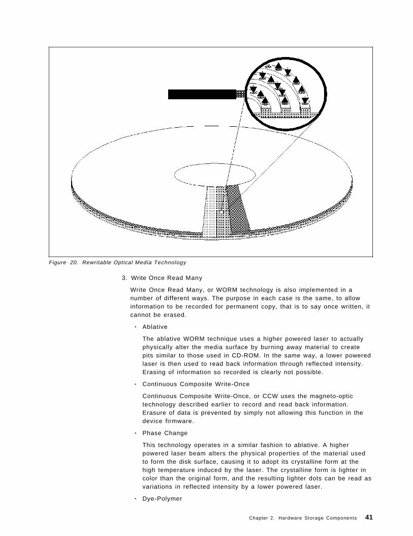
Figure 20. Rewritable Optical Media Technology
3. Write Once Read Many
Write Once Read Many, or WORM technology is also implemented in anumber of different ways. The purpose in each case is the same, to allowinformation to be recorded for permanent copy, that is to say once written, itcannot be erased.
• Ablative
The ablative WORM technique uses a higher powered laser to actuallyphysically alter the media surface by burning away material to createpits similar to those used in CD-ROM. In the same way, a lower poweredlaser is then used to read back information through reflected intensity.Erasing of information so recorded is clearly not possible.
• Continuous Composite Write-Once
Continuous Composite Write-Once, or CCW uses the magneto-optictechnology described earlier to record and read back information.Erasure of data is prevented by simply not allowing this function in thedevice firmware.
• Phase Change
This technology operates in a similar fashion to ablative. A higherpowered laser beam alters the physical properties of the material usedto form the disk surface, causing it to adopt its crystalline form at thehigh temperature induced by the laser. The crystalline form is lighter incolor than the original form, and the resulting lighter dots can be read asvariations in reflected intensity by a lower powered laser.
• Dye-Polymer
Chapter 2. Hardware Storage Components 41
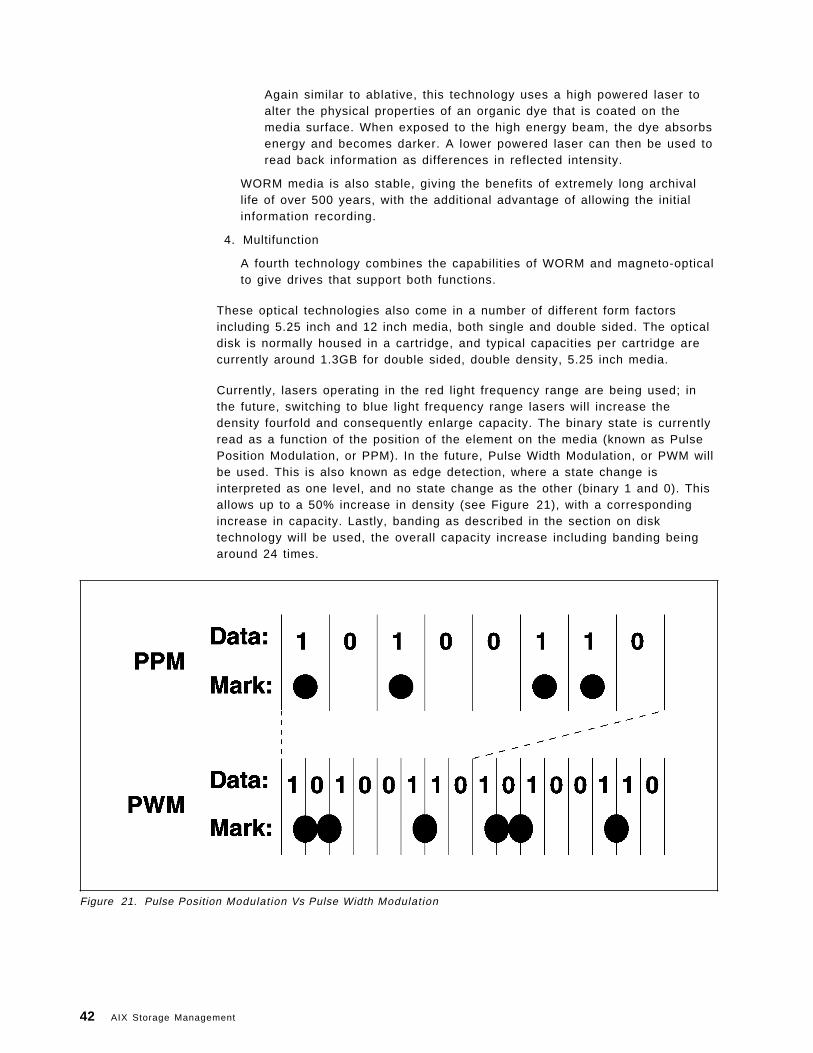
Again similar to ablative, this technology uses a high powered laser toalter the physical properties of an organic dye that is coated on themedia surface. When exposed to the high energy beam, the dye absorbsenergy and becomes darker. A lower powered laser can then be used toread back information as differences in reflected intensity.
WORM media is also stable, giving the benefits of extremely long archivallife of over 500 years, with the additional advantage of allowing the initialinformation recording.
4. Multifunction
A fourth technology combines the capabilities of WORM and magneto-opticalto give drives that support both functions.
These optical technologies also come in a number of different form factorsincluding 5.25 inch and 12 inch media, both single and double sided. The opticaldisk is normally housed in a cartridge, and typical capacities per cartridge arecurrently around 1.3GB for double sided, double density, 5.25 inch media.
Currently, lasers operating in the red light frequency range are being used; inthe future, switching to blue light frequency range lasers will increase thedensity fourfold and consequently enlarge capacity. The binary state is currentlyread as a function of the position of the element on the media (known as PulsePosition Modulation, or PPM). In the future, Pulse Width Modulation, or PWM willbe used. This is also known as edge detection, where a state change isinterpreted as one level, and no state change as the other (binary 1 and 0). Thisallows up to a 50% increase in density (see Figure 21), with a correspondingincrease in capacity. Lastly, banding as described in the section on disktechnology will be used, the overall capacity increase including banding beingaround 24 times.
Figure 21. Pulse Position Modulation Vs Pulse Width Modulation
42 AIX Storage Management
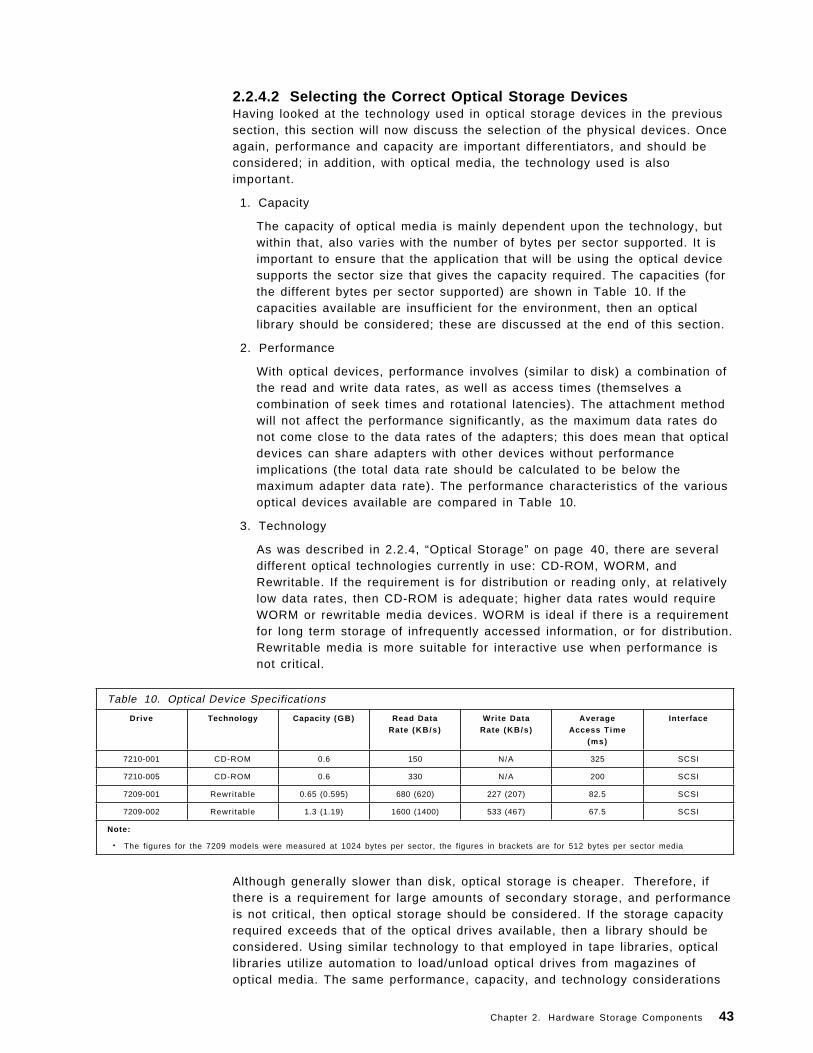
2.2.4.2 Selecting the Correct Optical Storage DevicesHaving looked at the technology used in optical storage devices in the previoussection, this section will now discuss the selection of the physical devices. Onceagain, performance and capacity are important differentiators, and should beconsidered; in addition, with optical media, the technology used is alsoimportant.
1. Capacity
The capacity of optical media is mainly dependent upon the technology, butwithin that, also varies with the number of bytes per sector supported. It isimportant to ensure that the application that will be using the optical devicesupports the sector size that gives the capacity required. The capacities (forthe different bytes per sector supported) are shown in Table 10. If thecapacities available are insufficient for the environment, then an opticallibrary should be considered; these are discussed at the end of this section.
2. Performance
With optical devices, performance involves (similar to disk) a combination ofthe read and write data rates, as well as access times (themselves acombination of seek times and rotational latencies). The attachment methodwill not affect the performance significantly, as the maximum data rates donot come close to the data rates of the adapters; this does mean that opticaldevices can share adapters with other devices without performanceimplications (the total data rate should be calculated to be below themaximum adapter data rate). The performance characteristics of the variousoptical devices available are compared in Table 10.
3. Technology
As was described in 2.2.4, “Optical Storage” on page 40, there are severaldifferent optical technologies currently in use: CD-ROM, WORM, andRewritable. If the requirement is for distribution or reading only, at relativelylow data rates, then CD-ROM is adequate; higher data rates would requireWORM or rewritable media devices. WORM is ideal if there is a requirementfor long term storage of infrequently accessed information, or for distribution.Rewritable media is more suitable for interactive use when performance isnot critical.
Table 10. Optical Device Specifications
Drive Technology Capacity (GB) Read DataRate (KB/s )
Wri te DataRate (KB/s )
AverageAccess Time
(ms)
Interface
7210-001 CD-ROM 0.6 150 N/A 325 SCSI
7210-005 CD-ROM 0.6 330 N/A 200 SCSI
7209-001 Rewri table 0.65 (0.595) 680 (620) 227 (207) 82.5 SCSI
7209-002 Rewri table 1.3 (1.19) 1600 (1400) 533 (467) 67.5 SCSI
Note:
• The figures for the 7209 models were measured at 1024 bytes per sector, the figures in brackets are for 512 bytes per sector media
Although generally slower than disk, optical storage is cheaper. Therefore, ifthere is a requirement for large amounts of secondary storage, and performanceis not critical, then optical storage should be considered. If the storage capacityrequired exceeds that of the optical drives available, then a library should beconsidered. Using similar technology to that employed in tape libraries, opticallibraries utilize automation to load/unload optical drives from magazines ofoptical media. The same performance, capacity, and technology considerations
Chapter 2. Hardware Storage Components 43
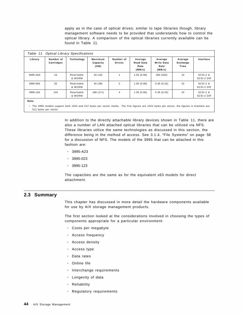
apply as in the case of optical drives; similar to tape libraries though, librarymanagement software needs to be provided that understands how to control theoptical library. A comparison of the optical libraries currently available can befound in Table 11.
Table 11. Optical Library Specifications
Library Number ofCartridges
Technology Max imumCapacity
(GB)
Number ofDrives
AverageRead Data
Rate( M B / s )
AverageWrite Data
Rate( M B / s )
AverageExchange
Time
Interface
3995-A63 16 Rewri table
& WORM
20 (19) 1 1.05 (0.96) 350 (320) 10 SCSI-2 &
SCSI-2 Diff
3995-063 32 Rewri table
& WORM
40 (38) 2 1.05 (0.96) 0.35 (0.32) 10 SCSI-2 &
SCSI-2 Diff
3995-163 144 Rewri table
& WORM
188 (171) 4 1.05 (0.96) 0.35 (0.32) 10 SCSI-2 &
SCSI-2 Diff
Note:
• The 3995 models support both 1024 and 512 bytes per sector media. The first figures are 1024 bytes per sector, the figures in brackets are
512 bytes per sector
In addition to the directly attachable library devices shown in Table 11, there arealso a number of LAN attached optical libraries that can be utilized via NFS.These libraries utilize the same technologies as discussed in this section, thedifference being in the method of access. See 3.1.4, “File Systems” on page 58for a discussion of NFS. The models of the 3995 that can be attached in thisfashion are:
• 3995-A23
• 3995-023
• 3995-123
The capacities are the same as for the equivalent x63 models for directattachment.
2.3 SummaryThis chapter has discussed in more detail the hardware components availablefor use by AIX storage management products.
The first section looked at the considerations involved in choosing the types ofcomponents appropriate for a particular environment:
• Costs per megabyte
• Access frequency
• Access density
• Access type
• Data rates
• Online life
• Interchange requirements
• Longevity of data
• Reliability
• Regulatory requirements
44 AIX Storage Management
Various decision scenarios were examined, including:
• Simple cases for just disk, tape, or optical
• More complicated environments where combinations of disk, tape, andoptical may be required
• The most complex cases where disk, tape, and optical are all required
The second section examined the characteristics of the hardware devicesthemselves with a view to selecting from the various products currentlyavailable.
Adapters were looked at from the points of view of:
• Technology
• Cabling requirements
• Performance/reliabil ity
• Addressability
• Device support
• Cost
Disks were looked at from the points of view of:
• Technology
• Capacity
• Subsystem performance, including RAID levels
• Availability and fault tolerance
Tape devices were looked at from the points of view of:
• Helical and longitudinal technologies
• Device and library capacities
• Availability
• Device and library performance
Optical devices were looked at from the points of view of:
• ROM, Rewritable, and WORM technologies
• Device and library capacities
• Device and library performance
Chapter 2. Hardware Storage Components 45

46 AIX Storage Management
Chapter 3. Operating System Software Components
This chapter is intended to discuss the various software components within theOperating System that are used to enable storage management. A briefoverview of the higher level software components available for storagemanagement is also included.
3.1 The Operating SystemThe operating system of a computer has been defined in many ways, butessentially it is a set of software interfaces and functions designed to provide anenvironment in which the hardware resources of the system can be utilizedeasily to do work. Within this definition there can be arbitrary levels ofcomplexity, ranging from simple operating systems that allow a single process toexecute at a time for a single user, to those that manage multiple processors,large arrays of disk, huge amounts of real memory, as well as many differentdevices on behalf of hundreds of users, each running several processesconcurrently.
The operating system can be subdivided into a number of components, each ofwhich perform essential tasks. This section will focus on those elements relatedto storage management.
3.1.1 Page SpaceAn application consists of four main elements:
1. Library
The library segment contains shared instructions that perform commonfunctions that will be used by many processes.
2. Text
The text segment contains any static information such as text strings, tables,and instructions to the processor.
3. Data
The data segment contains variable information that the application will useand modify during the course of its operation.
4. Files
Files contain the information that the application will actually process toproduce output that the user requires.
The text and data segments form an entity known as the executable and arestored in a file system (file systems and the organization of disk space for theirsupport are described in more detail in 3.1.3, “Logical Volume Manager” onpage 51, and 3.1.4, “File Systems” on page 58), usually on disk. When the userwishes to run the application, the operating system must locate the executable inthe file system, and load it into real memory. Any shared libraries required, if notalready being used by other applications, and therefore already loaded, mustalso be loaded.
Copyright IBM Corp. 1994 47
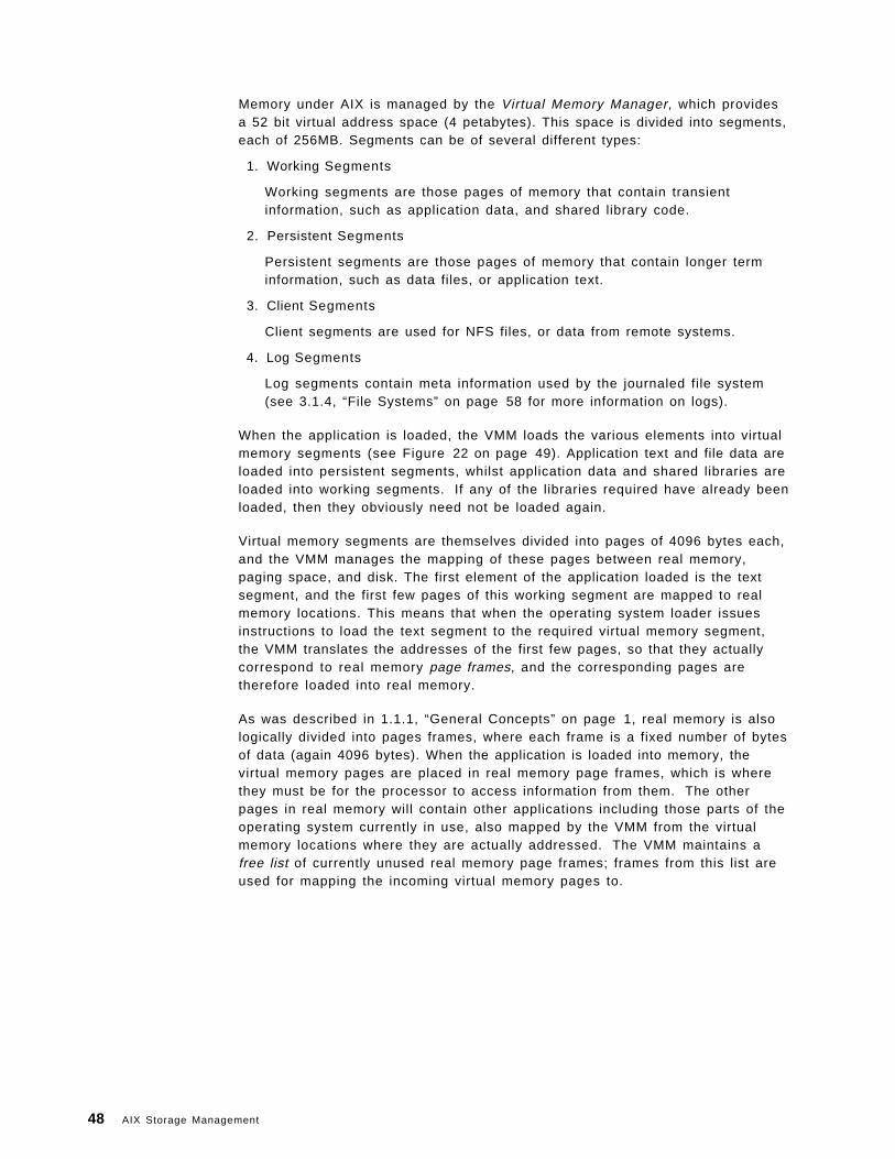
Memory under AIX is managed by the Virtual Memory Manager, which providesa 52 bit virtual address space (4 petabytes). This space is divided into segments,each of 256MB. Segments can be of several different types:
1. Working Segments
Working segments are those pages of memory that contain transientinformation, such as application data, and shared library code.
2. Persistent Segments
Persistent segments are those pages of memory that contain longer terminformation, such as data files, or application text.
3. Client Segments
Client segments are used for NFS files, or data from remote systems.
4. Log Segments
Log segments contain meta information used by the journaled file system(see 3.1.4, “File Systems” on page 58 for more information on logs).
When the application is loaded, the VMM loads the various elements into virtualmemory segments (see Figure 22 on page 49). Application text and file data areloaded into persistent segments, whilst application data and shared libraries areloaded into working segments. If any of the libraries required have already beenloaded, then they obviously need not be loaded again.
Virtual memory segments are themselves divided into pages of 4096 bytes each,and the VMM manages the mapping of these pages between real memory,paging space, and disk. The first element of the application loaded is the textsegment, and the first few pages of this working segment are mapped to realmemory locations. This means that when the operating system loader issuesinstructions to load the text segment to the required virtual memory segment,the VMM translates the addresses of the first few pages, so that they actuallycorrespond to real memory page frames, and the corresponding pages aretherefore loaded into real memory.
As was described in 1.1.1, “General Concepts” on page 1, real memory is alsologically divided into pages frames, where each frame is a fixed number of bytesof data (again 4096 bytes). When the application is loaded into memory, thevirtual memory pages are placed in real memory page frames, which is wherethey must be for the processor to access information from them. The otherpages in real memory will contain other applications including those parts of theoperating system currently in use, also mapped by the VMM from the virtualmemory locations where they are actually addressed. The VMM maintains afree list of currently unused real memory page frames; frames from this list areused for mapping the incoming virtual memory pages to.
48 AIX Storage Management
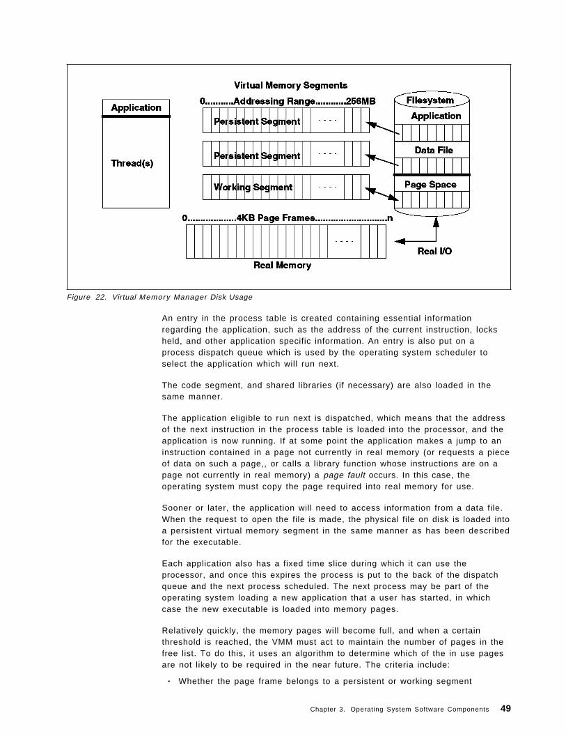
Figure 22. Virtual Memory Manager Disk Usage
An entry in the process table is created containing essential informationregarding the application, such as the address of the current instruction, locksheld, and other application specific information. An entry is also put on aprocess dispatch queue which is used by the operating system scheduler toselect the application which will run next.
The code segment, and shared libraries (if necessary) are also loaded in thesame manner.
The application eligible to run next is dispatched, which means that the addressof the next instruction in the process table is loaded into the processor, and theapplication is now running. If at some point the application makes a jump to aninstruction contained in a page not currently in real memory (or requests a pieceof data on such a page,, or calls a library function whose instructions are on apage not currently in real memory) a page fault occurs. In this case, theoperating system must copy the page required into real memory for use.
Sooner or later, the application will need to access information from a data file.When the request to open the file is made, the physical file on disk is loaded intoa persistent virtual memory segment in the same manner as has been describedfor the executable.
Each application also has a fixed time slice during which it can use theprocessor, and once this expires the process is put to the back of the dispatchqueue and the next process scheduled. The next process may be part of theoperating system loading a new application that a user has started, in whichcase the new executable is loaded into memory pages.
Relatively quickly, the memory pages will become full, and when a certainthreshold is reached, the VMM must act to maintain the number of pages in thefree list. To do this, it uses an algorithm to determine which of the in use pagesare not likely to be required in the near future. The criteria include:
• Whether the page frame belongs to a persistent or working segment
Chapter 3. Operating System Software Components 49
• If persistent, whether it contains program text, or file data
• Whether the page frame has caused page faults before (page faults areexplained shortly)
• If so, whether the faults were new faults, or repages (a repage is a page ofinformation that has been required more than once)
• If repages, how many
• User tunable threshold parameters
Pages selected in this way (enough to bring the number of used pages backbelow the threshold) are paged out, and page frames thus freed added to thefree list. The decisions are designed to favor those types of segment most likelyto be required in the near future, such as program text data, working segments,and highly accessed information.
The actions taken for paging out (or swapping) vary depending upon the type ofsegment from which the page comes, as well as its current state. If the page isfrom a working segment, then it is copied to an area of disk reserved for thispurpose known as page space. The VMM changes the mapping to reflect thatthe page is no longer in real memory, so that if a jump to an address (or requestfor data at an address) on this page occurs, a page fault will result causing thepage to be reloaded. This is the case for any working segment page out. Thepage is then added to the free list.
If the page is from a persistent segment, then the VMM will check to seewhether the page has been altered since it was first loaded, if not then the pageis just added to the free list; if a change has happened, then the page is firstwritten out to its original location on disk (usually in a file system). Again, theVMM changes the virtual memory mapping to point to the pages new locationback on disk, and then adds the freed real memory page to the free list.Utilization of disk in this fashion is known as single level storage.
Thus page space is used as an extension to real memory for situations wheremore real memory than is available for working segments is necessary.Persistent memory segments use their original locations on disk as overflow. Inthis way, the VMM is able to effectively use more real memory than is physicallyavailable on the system, as well as provide a huge address space.
There are certain mechanisms for file access such as the mmap() subroutine, oraccessing files via shared memory segments that will cause the file to be loadedinto a working segment in virtual memory. In these cases, the file informationwill be treated in the same way as data or libraries and page faults may result inparts being paged out to page space. Applications using these mechanisms willrequire much more page space, particularly if large files are to be accessed.
The operating system monitors the number of free pages in paging space, andwhen this falls below a certain level, all applications currently running on thesystem are informed of the situation via a SIGDANGER signal. If the number offree pages should then fall further, below a second threshold, those processesusing the most paging space will be sent the SIGKILL signal. This will continueuntil the number of free pages has risen above the danger level. Well behavedapplications will trap the SIGDANGER signal, and upon receipt, free up as muchpage space as they can by releasing resources.
50 AIX Storage Management
As can be seen, the allocation of paging space is critical to the operation of thecomputer system. Furthermore, the design of the storage subsystems generallywill have a big impact due to the concept of single level storage. Theseconsiderations are taken into account in Chapter 6, “General AIX StorageManagement” on page 95 and Chapter 5, “Storage Subsystem Design” onpage 79, which cover design and management.
3.1.2 Device DriversWhenever an operating system component or an application needs to interactwith a physical device, such as a disk or tape, it does so through servicesprovided by another element of the operating system known as a device driver.Device drivers provide a common mechanism for accessing the devices that theysupport.
Device drivers are treated as though they are ordinary files; thus when aprocess needs to communicate with a device, it uses the open subroutine toinitialize the interface, and can then use the read and write calls to access data.Control of the device is accomplished using the ioctl calls, and when the taskrequiring the device is complete, the interface is ended with the closesubroutine.
There are two main types of device driver; those designed for character orienteddevices, such as terminals, and printers, and those designed for block devices,such as disks or tapes. Storage management devices are usually block devices,as this is more efficient for transfer of larger quantities of information.
Device drivers normally consist of two parts:
1. The top half
This half is responsible for interacting with requestors, blocking and bufferingdata, queuing up requests for service, and handling error recovery andlogging.
2. The bottom half
This half is responsible for the actual I/O to and from the device, and canperform some preprocessing on requests, such as sorting reads from disksfor maximum efficiency.
Device drivers provide the primary interface to devices. The logical volumemanager, which is discussed in the next section also provides a device driverinterface to higher level software, and makes use of the services provided bydevice drivers to communicate with the physical devices themselves. A fullerunderstanding of device drivers is really only necessary for those readers whointend to develop applications that will interact directly with storage devices,such as tape or optical library managers. More information can be found in the″Device Driver Concepts Overview″ in the InfoExplorer* online hypertextdocumentation.
3.1.3 Logical Volume ManagerThe logical volume concept defines a higher level interface transparent toapplications and users, that allows the division, allocation, and management offixed disk storage space. This concept is implemented as a set of operatingsystem commands, subroutines, device drivers, and tools that are collectively
Chapter 3. Operating System Software Components 51
known as the Logical Volume Manager (LVM). This section is relevant to bothAIX Version 3 and AIX Version 4, though any differences will be highlighted.
3.1.3.1 Logical Volume Manager TerminologyThere are a number of specialized terms used to describe the various entitiesthat comprise Logical Volume Management.
Physical Volumes: The physical disk drive itself forms the basis of LogicalVolume Management. Before a disk can be used by the system, it must bedefined. Each disk is assigned certain configuration and identification informationthat together define the disk as a Physical Volume (PV). This information isphysically recorded on the disk and includes a Physical Volume Identifier (PVid)that uniquely identifies it. The disk is also assigned a physical volume name,typically hdiskx where x is a system unique number. This physical volume nameis also used for the low level device driver interface to the disk (for example/dev/hdisk0).
Volume Groups:: A collection of between 1 and 32 physical volumes is known asa Volume Group (VG). When physical volumes are created, they must be addedto a volume group in order to be used. A physical volume can only be in onevolume group on a system, though there can be multiple volume groups. Volumegroup information includes a unique Volume Group Identifier (VGid), and thePVids of all physical volumes in the volume group, as well as various statusinformation. Each disk in the volume group has an area on disk known as theVGDA or Volume Group Descriptor Area, where this information is stored. TheVGDA also contains information describing all of the logical volumes (discussedlater in this section) that exist in the volume group.
If more than 32 physical volumes are attached to a system then more than onevolume group will definitely be required. It is usually sensible to design thesystem such that different types of information are stored in different volumegroups though. For example, operating system information contained in onevolume group, and user information in a separate one, can assist inmanagement and in particular recovery; should a disk fault occur in a physicalvolume from one volume group, then only information from that volume groupwill be affected.
Under AIX Version 3 and AIX Version 4, up to 255 volume groups can be defined.
Physical Partitions: When a physical volume is added into a volume group, thespace on the physical volume is divided up into equal chunks known as PhysicalPartitions (PPs). The physical partition size is set when a volume group iscreated, and all physical volumes that are added to the volume group inherit thevalue. The physical partition size can range from 1 to 256MB, and must be apower of 2, the AIX default being 4MB. Up to 1016 physical partitions can bedefined per physical volume under AIX Version 3 and AIX Version 4.
This is the smallest unit of disk space allocation in the logical volume paradigm.Smaller units increase allocation flexibility at the cost of increased managementoverhead.
Logical Partitions: A Logical Partition (LP) is effectively a pointer to from 1 to 3physical partitions, this number specified when a logical volume (see nextsection) is created. Information written to a logical partition will be physicallywritten to the physical partitions pointed to. Thus the number of physical
52 AIX Storage Management
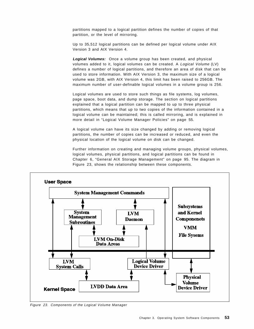
partitions mapped to a logical partition defines the number of copies of thatpartition, or the level of mirroring.
Up to 35,512 logical partitions can be defined per logical volume under AIXVersion 3 and AIX Version 4.
Logical Volumes: Once a volume group has been created, and physicalvolumes added to it, logical volumes can be created. A Logical Volume (LV)defines a number of logical partitions, and therefore an area of disk that can beused to store information. With AIX Version 3, the maximum size of a logicalvolume was 2GB, with AIX Version 4, this limit has been raised to 256GB. Themaximum number of user-definable logical volumes in a volume group is 256.
Logical volumes are used to store such things as file systems, log volumes,page space, boot data, and dump storage. The section on logical partitionsexplained that a logical partition can be mapped to up to three physicalpartitions, which means that up to two copies of the information contained in alogical volume can be maintained; this is called mirroring, and is explained inmore detail in “Logical Volume Manager Policies” on page 55.
A logical volume can have its size changed by adding or removing logicalpartitions, the number of copies can be increased or reduced, and even thephysical location of the logical volume on disk can be changed.
Further information on creating and managing volume groups, physical volumes,logical volumes, physical partitions, and logical partitions can be found inChapter 6, “General AIX Storage Management” on page 95. The diagram inFigure 23, shows the relationship between these components.
Figure 23. Components of the Logical Volume Manager
Chapter 3. Operating System Software Components 53
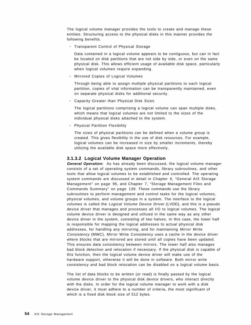
The logical volume manager provides the tools to create and manage theseentities. Structuring access to the physical disks in this manner provides thefollowing benefits.
• Transparent Control of Physical Storage
Data contained in a logical volume appears to be contiguous, but can in factbe located on disk partitions that are not side by side, or even on the samephysical disk. This allows efficient usage of available disk space, particularlywhen logical volumes require expanding.
• Mirrored Copies of Logical Volumes
Through being able to assign multiple physical partitions to each logicalpartition, copies of vital information can be transparently maintained, evenon separate physical disks for additional security.
• Capacity Greater than Physical Disk Sizes
The logical partitions comprising a logical volume can span multiple disks,which means that logical volumes are not limited to the sizes of theindividual physical disks attached to the system.
• Physical Partition Flexibility
The sizes of physical partitions can be defined when a volume group iscreated. This gives flexibility in the use of disk resources. For example,logical volumes can be increased in size by smaller increments, therebyutilizing the available disk space more effectively.
3.1.3.2 Logical Volume Manager OperationGeneral Operation: As has already been discussed, the logical volume managerconsists of a set of operating system commands, library subroutines, and othertools that allow logical volumes to be established and controlled. The operatingsystem commands are discussed in detail in Chapter 6, “General AIX StorageManagement” on page 95, and Chapter 7, “Storage Management Files andCommands Summary” on page 139. These commands use the librarysubroutines to perform management and control tasks for the logical volumes,physical volumes, and volume groups in a system. The interface to the logicalvolumes is called the Logical Volume Device Driver (LVDD), and this is a pseudodevice driver that manages and processes all I/O to logical volumes. The logicalvolume device driver is designed and utilized in the same way as any otherdevice driver in the system, consisting of two halves. In this case, the lower halfis responsible for mapping the logical addresses to actual physical diskaddresses, for handling any mirroring, and for maintaining Mirror WriteConsistency (MWC). Mirror Write Consistency uses a cache in the device driverwhere blocks that are mirrored are stored until all copies have been updated.This ensures data consistency between mirrors. The lower half also managesbad block detection and relocation if necessary. If the physical disk is capable ofthis function, then the logical volume device driver will make use of thehardware support, otherwise it will be done in software. Both mirror writeconsistency and bad block relocation can be disabled on a logical volume basis.
The list of data blocks to be written (or read) is finally passed by the logicalvolume device driver to the physical disk device drivers, who interact directlywith the disks. In order for the logical volume manager to work with a diskdevice driver, it must adhere to a number of criteria, the most significant ofwhich is a fixed disk block size of 512 bytes.
54 AIX Storage Management
The relationship between the various software layers involved in disk accesswith the logical volume manager is shown in Figure 24 on page 55.
Figure 24. Relationship Between the LVM and other Components
Quorum Checking: In order for a volume group to be accessible to the system,it must be varied on. The process of varying on a volume group is discussed in6.3.4, “Varying On and Varying Off Volume Groups” on page 108. During thisprocess, the logical volume manager reads management information from thephysical volumes in the volume group. This information includes the volumegroup descriptor area already mentioned in 3.1.3.1, “Logical Volume ManagerTerminology” on page 52, and another on-disk information repository known asthe Volume Group Status Area (VGSA), which is also stored on all physicalvolumes in the volume group. The VGSA contains information regarding thestate of physical partitions and volumes in the volume group, such as whetherphysical partitions are stale (used for mirroring, but not reflecting the latestinformation), and whether physical volumes are accessible or not. The VGDA ismanaged by the subroutine library, and the VGSA is maintained by the LVDD. Ifthe vary on command cannot access a physical volume in the volume group itwill mark it as missing in the VGDA. For the command to succeed, a quorum ofphysical volumes must be available. A quorum is defined as a majority of VGDAsand VGSAs (more than half of the total number available). The only situationwhere this is slightly different is in the case where there are one or two physicalvolumes in a volume group. In this case two VGDAs and VGSAs will be written toone disk, and one (or none if only one disk) to the other. If the disk with two setsis inaccessible, then a quorum will not be achieved and the vary on will fail. Fortechniques to recover from quorum failure, see Appendix C, “General VolumeGroup Recovery” on page 345.
Logical Volume Manager Policies: When logical volumes are created, there area number of attributes that can be defined for them that govern their subsequentoperation in terms of performance and availability. These attributes are reallypolicies that the logical volume manager enforces for the logical volume andinclude the following:
Chapter 3. Operating System Software Components 55
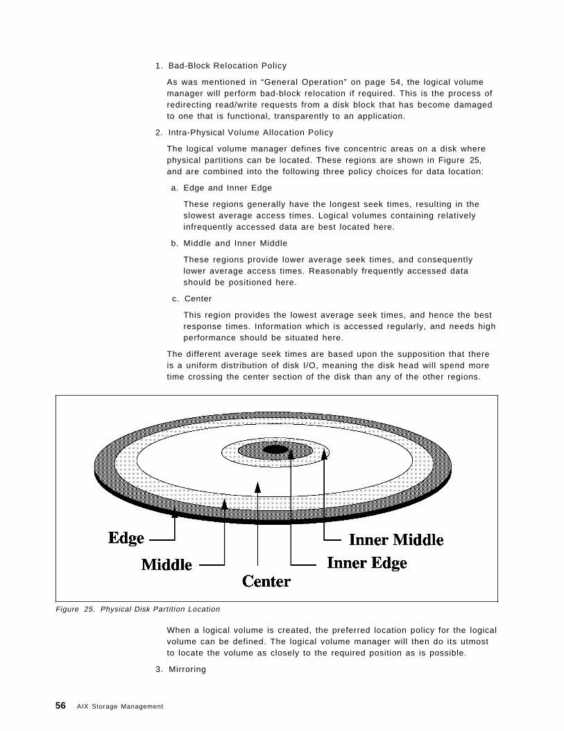
1. Bad-Block Relocation Policy
As was mentioned in “General Operation” on page 54, the logical volumemanager will perform bad-block relocation if required. This is the process ofredirecting read/write requests from a disk block that has become damagedto one that is functional, transparently to an application.
2. Intra-Physical Volume Allocation Policy
The logical volume manager defines five concentric areas on a disk wherephysical partitions can be located. These regions are shown in Figure 25,and are combined into the following three policy choices for data location:
a. Edge and Inner Edge
These regions generally have the longest seek times, resulting in theslowest average access times. Logical volumes containing relativelyinfrequently accessed data are best located here.
b. Middle and Inner Middle
These regions provide lower average seek times, and consequentlylower average access times. Reasonably frequently accessed datashould be positioned here.
c. Center
This region provides the lowest average seek times, and hence the bestresponse times. Information which is accessed regularly, and needs highperformance should be situated here.
The different average seek times are based upon the supposition that thereis a uniform distribution of disk I/O, meaning the disk head will spend moretime crossing the center section of the disk than any of the other regions.
Figure 25. Physical Disk Partition Location
When a logical volume is created, the preferred location policy for the logicalvolume can be defined. The logical volume manager will then do its utmostto locate the volume as closely to the required position as is possible.
3. Mirroring
56 AIX Storage Management
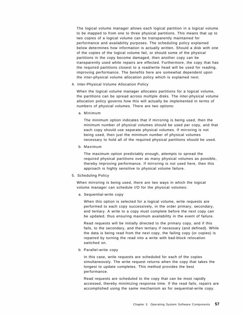
The logical volume manager allows each logical partition in a logical volumeto be mapped to from one to three physical partitions. This means that up totwo copies of a logical volume can be transparently maintained forperformance and availability purposes. The scheduling policy explainedbelow determines how information is actually written. Should a disk with oneof the copies of the logical volume fail, or should some of the physicalpartitions in the copy become damaged, then another copy can betransparently used while repairs are effected. Furthermore, the copy that hasthe required partitions closest to a read/write head will be used for reading,improving performance. The benefits here are somewhat dependent uponthe inter-physical volume allocation policy which is explained next.
4. Inter-Physical Volume Allocation Policy
When the logical volume manager allocates partitions for a logical volume,the partitions can be spread across multiple disks. The inter-physical volumeallocation policy governs how this will actually be implemented in terms ofnumbers of physical volumes. There are two options:
a. Minimum
The minimum option indicates that if mirroring is being used, then theminimum number of physical volumes should be used per copy, and thateach copy should use separate physical volumes. If mirroring is notbeing used, then just the minimum number of physical volumesnecessary to hold all of the required physical partitions should be used.
b. Maximum
The maximum option predictably enough, attempts to spread therequired physical partitions over as many physical volumes as possible,thereby improving performance. If mirroring is not used here, then thisapproach is highly sensitive to physical volume failure.
5. Scheduling Policy
When mirroring is being used, there are two ways in which the logicalvolume manager can schedule I/O for the physical volumes:
a. Sequential-write copy
When this option is selected for a logical volume, write requests areperformed to each copy successively, in the order primary, secondary,and tertiary. A write to a copy must complete before the next copy canbe updated, thus ensuring maximum availability in the event of failure.
Read requests will be initially directed to the primary copy, and if thisfails, to the secondary, and then tertiary if necessary (and defined). Whilethe data is being read from the next copy, the failing copy (or copies) isrepaired by turning the read into a write with bad-block relocationswitched on.
b. Parallel-write copy
In this case, write requests are scheduled for each of the copiessimultaneously. The write request returns when the copy that takes thelongest to update completes. This method provides the bestperformance.
Read requests are scheduled to the copy that can be most rapidlyaccessed, thereby minimizing response time. If the read fails, repairs areaccomplished using the same mechanism as for sequential-write copy.
Chapter 3. Operating System Software Components 57
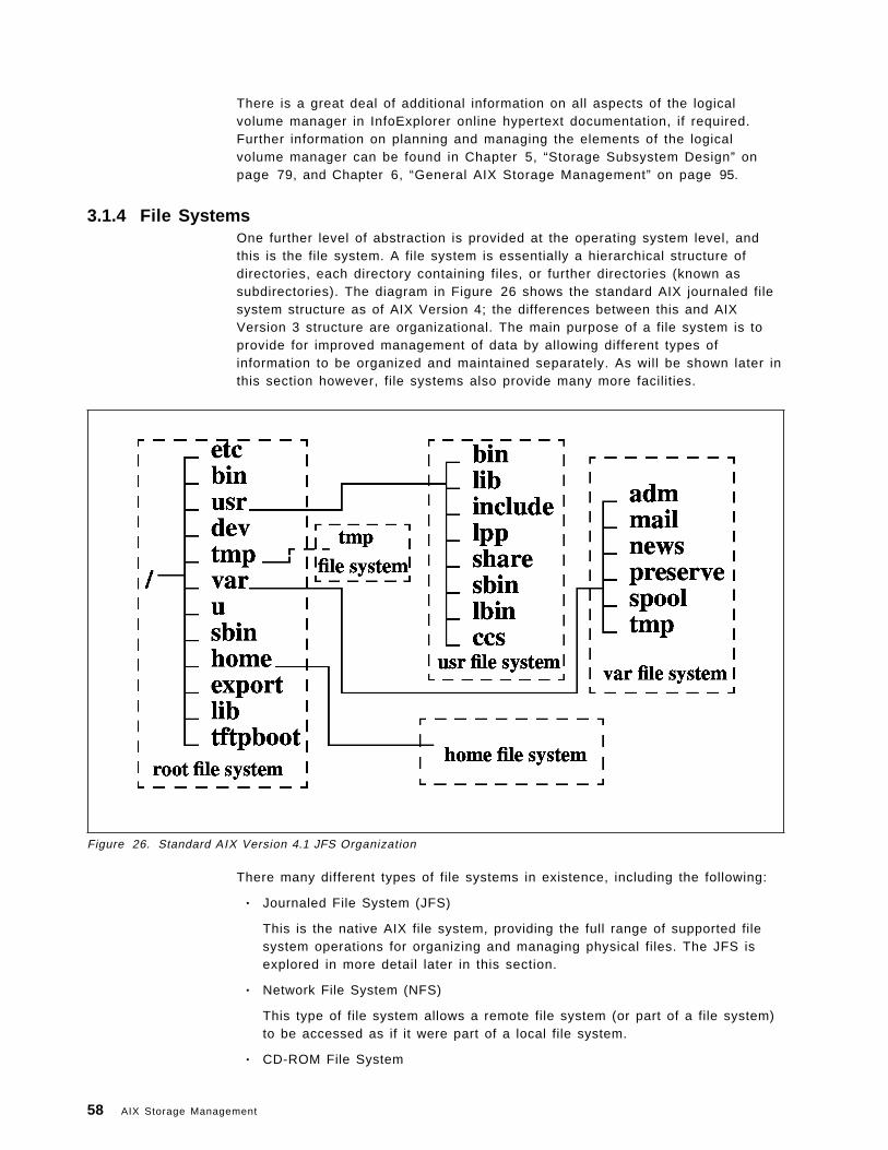
There is a great deal of additional information on all aspects of the logicalvolume manager in InfoExplorer online hypertext documentation, if required.Further information on planning and managing the elements of the logicalvolume manager can be found in Chapter 5, “Storage Subsystem Design” onpage 79, and Chapter 6, “General AIX Storage Management” on page 95.
3.1.4 File SystemsOne further level of abstraction is provided at the operating system level, andthis is the file system. A file system is essentially a hierarchical structure ofdirectories, each directory containing files, or further directories (known assubdirectories). The diagram in Figure 26 shows the standard AIX journaled filesystem structure as of AIX Version 4; the differences between this and AIXVersion 3 structure are organizational. The main purpose of a file system is toprovide for improved management of data by allowing different types ofinformation to be organized and maintained separately. As will be shown later inthis section however, file systems also provide many more facilities.
Figure 26. Standard AIX Version 4.1 JFS Organization
There many different types of file systems in existence, including the following:
• Journaled File System (JFS)
This is the native AIX file system, providing the full range of supported filesystem operations for organizing and managing physical files. The JFS isexplored in more detail later in this section.
• Network File System (NFS)
This type of file system allows a remote file system (or part of a file system)to be accessed as if it were part of a local file system.
• CD-ROM File System
58 AIX Storage Management
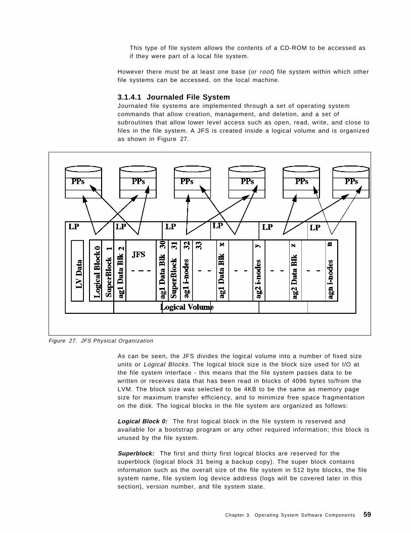
This type of file system allows the contents of a CD-ROM to be accessed asif they were part of a local file system.
However there must be at least one base (or root) file system within which otherfile systems can be accessed, on the local machine.
3.1.4.1 Journaled File SystemJournaled file systems are implemented through a set of operating systemcommands that allow creation, management, and deletion, and a set ofsubroutines that allow lower level access such as open, read, write, and close tofiles in the file system. A JFS is created inside a logical volume and is organizedas shown in Figure 27.
Figure 27. JFS Physical Organization
As can be seen, the JFS divides the logical volume into a number of fixed sizeunits or Logical Blocks. The logical block size is the block size used for I/O atthe file system interface - this means that the file system passes data to bewritten or receives data that has been read in blocks of 4096 bytes to/from theLVM. The block size was selected to be 4KB to be the same as memory pagesize for maximum transfer efficiency, and to minimize free space fragmentationon the disk. The logical blocks in the file system are organized as follows:
Logical Block 0: The first logical block in the file system is reserved andavailable for a bootstrap program or any other required information; this block isunused by the file system.
Superblock: The first and thirty first logical blocks are reserved for thesuperblock (logical block 31 being a backup copy). The super block containsinformation such as the overall size of the file system in 512 byte blocks, the filesystem name, file system log device address (logs will be covered later in thissection), version number, and file system state.
Chapter 3. Operating System Software Components 59
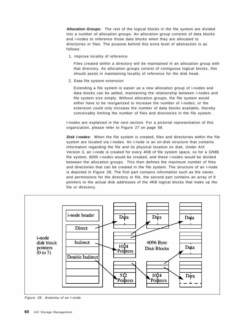
Allocation Groups: The rest of the logical blocks in the file system are dividedinto a number of allocation groups. An allocation group consists of data blocksand i-nodes to reference those data blocks when they are allocated todirectories or files. The purpose behind this extra level of abstraction is asfollows:
1. Improve locality of reference
Files created within a directory will be maintained in an allocation group withthat directory. As allocation groups consist of contiguous logical blocks, thisshould assist in maintaining locality of reference for the disk head.
2. Ease file system extension
Extending a file system is easier as a new allocation group of i-nodes anddata blocks can be added, maintaining the relationship between i-nodes andfile system size simply. Without allocation groups, the file system wouldeither have to be reorganized to increase the number of i-nodes, or theextension could only increase the number of data blocks available, therebyconceivably limiting the number of files and directories in the file system.
I-nodes are explained in the next section. For a pictorial representation of thisorganization, please refer to Figure 27 on page 59.
Disk i-nodes: When the file system is created, files and directories within the filesystem are located via i-nodes. An i-node is an on-disk structure that containsinformation regarding the file and its physical location on disk. Under AIXVersion 3, an i-node is created for every 4KB of file system space, so for a 32MBfile system, 8000 i-nodes would be created, and these i-nodes would be dividedbetween the allocation groups. This then defines the maximum number of filesand directories that can be created in the file system. The structure of an i-nodeis depicted in Figure 28. The first part contains information such as the owner,and permissions for the directory or file, the second part contains an array of 8pointers to the actual disk addresses of the 4KB logical blocks that make up thefile or directory.
Figure 28. Anatomy of an I-node
60 AIX Storage Management
For files that can fit within the array storage area, such as most links, the file isactually stored in the i-node itself, thus saving disk space.
For a file of size up to 32KB, each i-node pointer will directly reference a logicalblock on the disk. For example, if the file is of size 27KB, then the first sevenpointers will be required, the last pointer referencing a 4KB logical blockcontaining the last 3KB of the file.
For files up to 4MB, the i-node points to a logical block that contains 1024pointers to logical blocks that will contain the files data; this gives a file size ofup to 1024 x 4096 or 4MB.
For files greater in size than this, the i-node points to a logical block thatcontains 512 pointers to logical blocks that each contain 1024 pointers to thelogical blocks that will actually contain the files data; this gives a maximum filesize of 512 x 1024 x 4096 or 2GB.
The mapping of file names to i-node numbers is stored within directory files.
The maximum size of the file system under AIX Version 3 is limited to 2GB. Thisis due to limitations in the size of the internal pointer used by some system callsto navigate the file system; the pointer is defined as a signed integer whichmeans there are 31 bits available for addressing. This gives a maximum rangeof 2 to the power 31, or 2GB.
AIX Version 4 Enhancements to the JFS
1. Fragments
While generally efficient from the point of view of loading into memory andpreventing physical disk fragmentation, having a fixed logical block size canhave drawbacks. If the majority of files stored in the file system are small(less than 1 logical block in size), then there will be a great deal of wasteddisk space in the accumulation of those portions of the logical blocks thatremain unused by the smaller files. If all files are less than half of a logicalblock in size, for example, then half of the total file system space will beunused, even though the file system is full.
In order to address this type of situation, AIX Version 4 introduces theconcept of the fragment. A fragment is the smallest unit of file system diskspace allocation, and can be 512, 1024, 2048, or 4096 bytes in size. Thefragment size is defined at JFS creation time and is stored in the superblock.
2. Number of Bytes Per i-node
Under AIX Version 3, the number of i-nodes created for a file system wasfixed, as discussed in the section on i-nodes. With AIX Version 4, it is nowpossible to vary the number of i-nodes created within a file system, andtherefore the amount of space required by the i-node structures can betailored to maximize utilization of the file system. If only a few very largefiles are going to be created in a file system, then it is a waste of space togenerate 8000 i-node structures, and therefore the value of the Number ofBytes Per i-node or NBPI, should be increased. For example, if the NBPI isset to 16KB, then in a file system of size 32MB, 2000 i-nodes would becreated rather than 8000 as in AIX Version 3.
3. Compression
Chapter 3. Operating System Software Components 61
Another new feature in AIX Version 4 is JFS compression. This facilityprovides for compression of regular files (as opposed to directories or links).The compression is implemented on a logical block basis which means thatwhen a logical block of file data is to be written, an entire logical block isallocated for it; the logical block is then compressed and the number offragments now required as a result of the compression, actually allocated.Thus in contrast to a fragment file system which only allocates fragments forthe final logical blocks of files less than 32KB in size, compressed filesystems allocate fragments for every logical block in every file.
Compression is done block by block in order to fulfill the requirements forefficient random I/O. The algorithm used by default is LZ1, althoughuser-defined compression algorithms are also supported.
4. File System Size
As discussed previously, the maximum size of a file system under AIXVersion 3 was 2GB. With AIX Version 4, this maximum has been increased to256GB. This increase has been achieved by changing the file systempointers and data types to 64 bits; the limitations restricting the maximumsize are now JFS data structure and algorithm related.
These enhancements are described in more detail in Chapter 4, “AIX Version 4Storage Management Enhancements” on page 69.
3.1.4.2 Network File SystemNFS allows files and directories located on other systems to be incorporated intoa local file system and accessed as though they were a part of that file system.NFS provides its services on a client-server basis. Server systems can makeselected files and directories available for access by client systems. NFSprovides a number of services, including the following:
• Mount Service
This service allows clients to mount the portion of the remote file system thatthey wish to access into a local file system. Mounting is discussed in moredetail later in this section.
• Remote File Access
This service fulfills requests for file activity from the client to server (such asopens, reads, and writes).
• Remote Execution Service
This service provides authorized clients with the ability to executecommands on the server.
• Remote System Statistics Service
This service provides statistics on the recent availability of the server.
• Remote User Listing Service
This service provides information to clients on users of the server system.
NFS installation, configuration and management are covered in detail in theInfoExplorer online hypertext documentation.
NFS operation is stateless, which means that the server does not maintain anytransaction information on behalf of clients. Each file operation is atomic, whichmeans that once complete, no information on the operation is retained. Thus if a
62 AIX Storage Management
connection should fail, it is up to the client to maintain any synchronization ortransaction logging to ensure consistency.
3.1.4.3 Other File SystemsAs has been explained in this section, file systems provide an interface thatsimplifies management and access to information. The native file system underAIX is the JFS, but there are other types such as NFS for remote files, as well asthe following:
• CD-ROM File System
This file system provides access to information stored on a CD-ROM, such asthe infoExplorer hypertext information. Once created (see InfoExplorer fordetails) a CD-ROM file system can be mounted and accessed like any other.
• File Storage Facility/6000 MFS
The File Storage Facility product (FSF) is discussed in overview in B.2, “AIXFile Storage Facility/6000” on page 340. This product provides a cache filesystem on the client machine where files currently being accessed reside.Viewing the contents of this file system can show more files than couldactually fit within the physical space on the client. This is accomplishedthrough the provision of another file system type known as MFS. The MFSintercepts requests for file operations and works out whether the requiredfile is currently in local cache or stored remotely at the server; if remotelystored, the file is transparently copied to the local cache for use. The MFSalso manages the removal from cache to the server of files that have notbeen accessed for a defined period, or the largest files, so as to maintainenough working space in the cache.
The MFS is created automatically when FSF/6000 is configured. For moreinformation on FSF/6000, see the documentation.
• Andrew File System** (AFS**)
The Andrew File System, or AFS, provides a similar basic service to NFS inthat it allows machines to access remote file systems as though they werelocal. The major difference is that AFS defines its own hierarchy, wheremany machines can participate in mounting sections of their local filesystems into the hierarchy. Client machines that are authorized can thenmount the entire AFS hierarchy into their local file system structure, andthereby access information on a wide range of machines and file systems asthough it were local.
For more information on AFS, please refer to the product manuals.
3.1.4.4 Accessing File SystemsOnce a file system of whatever type has been created, it must be mounted inorder to access the information within it. The process of mounting creates theconnection between an existing and accessible local file system mount point andthe root directory of the directory structure to be accessed. A mount point can beeither a directory or a file in the local file system. If a new local file system, orremote directory structure (using NFS for example) is to be accessed, then itmust be mounted over a directory. If only a single file is to be accessed then itmust be mounted over a local file. As shown in Figure 26 on page 58, the AIXoperating system starts with a root file system into which the /usr, /var, /tmp,and /home file systems are mounted at boot time. Any other file systemsrequired can then be mounted wherever required (assuming relevantpermissions).
Chapter 3. Operating System Software Components 63
3.2 Higher Level ToolsSo far in this chapter the basic operating system support providing access toinformation stored on physical media (such as disk) has been discussed. Thisnext section will look briefly at some higher level functions provided either bythe operating system, or by applications designed to enhance storagemanagement capabilit ies.
3.2.1 Backup/RestoreBackup facilities, as provided by the operating system, enable all information(including both user and operating system data) to be copied (generally toremovable media such as tape), so that in the event of a major problem theinformation can be easily restored.
There are three main areas to consider when designing a backup strategy:
1. Which information should be backed up
There is usually a large amount of information stored in a computer system.Copying this information can take time, and there will usually be informationthat is not important enough to warrant concern (such as temporary files, ordata that has already been archived).
2. What technology should be used for the backups
This will depend on the quantity of information, length of time available forbackup, length of time information needs to be stored on backup media, andthe cost of the technology used. As has been discussed in previous sections,optical storage is generally faster and has longer potential shelf life, whilsttapes are cheaper and generally larger capacity.
3. When and how often should backups occur
There are several strategies that can be used, depending on the nature ofthe information produced by the business. For example, sites where there isa great deal of static reference information with little day to day change, andmaybe monthly updates to the static information could benefit from anincremental policy. This would mean taking full backups on a monthly basis,and only backing up the changed information daily. Organizations processinglarge amounts of information on a daily basis may choose to backup the datadaily.
The strategy chosen should reflect the business information cycles, but willalso be strongly tied to the criticality of the information. The decision issimply: how long can the business survive without key information. If theanswer is one day, then backups of the information must be scheduled atleast once a day.
Designing a backup strategy is an essential task, as however well maintained asystem is, the unexpected, by definition can always happen. Backup andrecovery planning and techniques are discussed in more detail in 5.5, “PlanningBackup Strategies” on page 89.
64 AIX Storage Management
3.2.2 Hierarchical Storage ManagementThus far, storage subsystems have been discussed from the point of view ofoperating system level access. That is to say, covering the various storagedevices available, their pros and cons, and the way in which they can be madeavailable to higher level user applications. There are also many intermediateand higher level applications that themselves provide services, both for systemadministrators, and for higher level management of storage on behalf of users.These types of application fall into the category of Hierarchical StorageManagement.
The premise behind hierarchical storage management is to categorize storagedevices in terms of their basic properties and provide automatic mechanisms toutilize them most efficiently within this context, usually in a networkedenvironment. For example, as has been discussed in 2.1.2, “How to Make theDecision” on page 18, the basic property classifications shown in Figure 14 onpage 21, apply. This implies that frequently accessed information, or informationthat requires high performance access (such as databases), should be locatedon fast disk devices. Older, less frequently accessed information, or informationwith less restrictive performance requirements, can be stored on optical media.Backup, archive, or long term information that is rarely accessed, can be storedon tape. The process of classifying information in this way, is however, really adynamic one, and therefore best done on a reasonably continuous basis. This iswhere hierarchical storage managers can be useful.
ADSTAR* Distributed Storage Manager (ADSM) for example, can manage disk,optical and tape storage in just this way. ADSM provides backup/restore andarchive/retrieve services to client systems in a distributed environment. Storagepools are maintained on the server machine that ADSM uses to fulfill clientrequests. These pools can be defined to form a hierarchy and information can beautomatically migrated between pools. For example, the first pool may becomposed of fast disk devices to support rapid satisfaction of client requests.However, if this pool becomes full, then information can be automaticallymigrated to another storage pool. Generally, the information so migrated will bethe less frequently accessed information, and so the lower level pool will becomposed of lower cost, slower, higher capacity devices, such as optical. Thehierarchy so defined is arbitrary, and can contain pools of tape devices lower inthe hierarchy, to which backup information can be directly (and automatically)written on behalf of clients, or to which even less regularly accessed archivedata can be migrated.
ADSM also has many other capabilities, and for a fuller description of these,please refer to Appendix B, “Higher Level Storage Management Products” onpage 337.
Some tools manage disk space at the client machine as well. FSF/6000 is anexample of such an application. In this case, the client fast disk space ismaintained merely as a cache (or window onto the real storage space). Wheninformation is created or changed in any way, it is stored in the cache at thelocal machine, but a copy is made and this is maintained at the server. When thecache approaches a predefined high water mark, or percentage utilization, datais automatically migrated to the server storage space, and a pointer to it left inthe cache. Subsequent requests for this information will result in the informationbeing transparently moved back (a copy is still maintained). In this way, thesmall client storage space can be made to seem much larger than it really is; in
Chapter 3. Operating System Software Components 65
addition, the server storage pool can be managed by a tool such as ADSM (atthe server) to provide automatic backup, archive and migration.
Using such tools additionally enhances storage management by providing acentralized mechanism for information management, which can be useful, notonly from resource utilization management, but also from security, generalavailability, and ease of use.
General information on some of the applications available in this area isavailable in Appendix B, “Higher Level Storage Management Products” onpage 337.
3.2.3 Media ManagementMedia management refers to the control of the attached storage devices. Thischapter has already looked at the operating system supplied mechanisms toenable this, including device drivers, the LVM, and file systems. In the previoustwo sections, backup and restore, and hierarchical storage managers have alsobeen discussed, which provide higher level functions for storage. Thecapabilities of the devices are thus made available through the operating systemcomponents, and through higher level tools. Generally, the higher levelapplications make use of the operating system provided components to accessthe required devices. There are some device types that cannot currently bemanaged by the operating system, including tape and optical libraries. In thesecases an alternative mechanism must be found to control the devices, ifrequired; ADSM for example provides the necessary support to control a rangeof libraries (both tape and optical). It is not always the case that the completefunctionality of a higher level tool be required, merely just the ability to managea tape library for a discrete system. In this case an alternative solution may benecessary in order to provide the library management component.
3.3 SummaryThis chapter has discussed in detail the operating system software componentsthat enable access and management of the physical storage devices, as well asthose aspects that require storage space for system operation. Higher levelfunctions provided by tools such as hierarchical storage managers,backup/restore operations, and management of the physical media were alsobriefly discussed.
1. Operating system
The components of the operating system discussed were:
• Paging
This section explained paging and the requirement for paging space as ameans to maximize the usage of available real memory. The completemechanism used to execute an application was outlined illustrating howsecondary storage can be used to supplement real memory and therebygreatly increase the address space of the system.
• Device drivers
This section discussed the components of the operating system thatprovide the low level management and access to physical devices. Thestructure and capabilities of device drivers was briefly explained.
• Logical Volume Manager
66 AIX Storage Management
The main component of storage management under AIX, the LVM wasexplained in reasonable detail in this section. LVM concepts such as:
− Physical Volumes− Volume Groups− Physical Partitions− Logical Partitions− Logical Volumes
were explained, as well as their interrelationships. LVM operations andservices were also described, including:
− Quorum checking− Bad block relocation− Intra-physical allocation policy− Mirroring− Inter-physical allocation policy− Scheduling policy
• File systems
The concept of file systems was then covered. The relationship of filesystems to the LVM as well as their general function were outlined. Thenative AIX file system, the JFS was then described in detail, including theAIX Version 3 implementation, and the enhancements provided with AIXVersion 4:
− Fragments− Number of bytes per i-node− Compression− File system size increase
The NFS and other file systems were then briefly discussed, followed bya concise outline of subsequent operating system procedures foraccessing file systems.
2. Higher level tools
The higher level tools discussed were:
• Backup/restore
The purpose and basic considerations involved in backing up a system toensure recovery in the event of failure were discussed in this section.
• Hierarchical Storage Management
The principles of hierarchical storage management as a means to makethe most effective use of available storage devices, as well as providebackup/restore and archive/retrieve services, were discussed in thissection. Several high level applications (including ADSM, and FSF/6000)were used as examples.
• Media Management
Certain devices provide extra capabilities that are not currently directlysupported by the operating system. Examples of this are tape and opticallibrary support. This section looks at the alternative methods availablefor utilizing such functionality.
Chapter 3. Operating System Software Components 67

68 AIX Storage Management
Chapter 4. AIX Version 4 Storage Management Enhancements
AIX Version 4 provides enhanced functional capabilities in the area of thestorage management. This chapter will examine these enhancements, in somedetail.
4.1 FragmentationFragmentation is a concept introduced in BSD UNIX** which enables systemadministrators to manage file systems in such a way that they make moreefficient use of the disk storage space available to them.
Research conducted in the area of disk space utilization has revealed that up to45% of disk space is wasted by file systems that use a 4KB block as theallocation unit. In AIX releases prior to AIX Version 4, the disk space allocationunit is in fact 4KB and not tunable, potentially giving rise to much wasted diskspace. In AIX Version 4 it is now possible to create journaled file systems withan allocation unit or fragment size specified as one of 512, 1024, 2048 or 4096bytes.
Although there is a distinct advantage in providing this enhancement forensuring optimal disk space utilization this can sometimes be at the expense ofperformance.
In AIX Version 4, as many whole fragments as necessary are used to store a fileor directory′s data. Consider that we have chosen to use a JFS fragment size of4KB and we are attempting to store file data which only partially fills a JFSfragment. Potentially, the amount of unused or wasted space in the partiallyfilled fragment can be quite high. For example, if only 500 bytes are stored inthis fragment then 3596 bytes will be wasted. However, if a smaller JFSfragment size, say 512 bytes, was used, the amount of wasted disk space wouldbe greatly reduced to only 12 bytes. It is, therefore, better to use small fragmentsizes if efficient use of available disk space is required.
Although small fragment sizes can be beneficial in reducing disk space wastage,this can have an adverse effect on disk I/O activity. For a file with a size of 4KBstored in a single fragment of 4KB, only one disk I/O operation would berequired to either read or write the file. If the choice of the fragment size was512 bytes, eight fragments would be allocated to this file and for a read or writeto complete, several additional disk I/O operations (disk seeks, data transfersand allocation activity) would be required. Therefore, for file systems which usea fragment size of 4KB, the number of disk I/O operations will be far less thanfor file systems which employ a smaller fragment size.
For files of greater than 32KB in size, whatever the fragment size, allocation isperformed in logical blocks of 4KB. The i-node pointers will therefore point to4KB logical blocks as before (indirection will also be the same). For those files ofup to 32KB in size, fragments come in to play. Consider a file of 17KB in size.The first 16KB of this file will be allocated logical blocks as before, the diskaddresses of these blocks pointed to by the first four pointers in the i-node. Thelast 1KB of the file will be allocated sufficient contiguous fragments to containthe remaining data, if available. Assuming a fragment size of 512 bytes, twofragments in this case. The fifth pointer in the i-node points to the disk address
Copyright IBM Corp. 1994 69
of the first fragment. In AIX Version 3, the first four bits of the disk blockaddresses were unused and therefore zeros. In AIX Version 4, whenfragmentation is used, the last three of these bits are used to indicate thenumber of fragments from the disk address that are required. To ensurecompatibility with previous releases, all zeros in these bits implies a full block offragments (which means that the disk address references a 4KB logical block),and therefore in this example eight fragments (using logic 8 - 0 = 8 fragments).So, for the final data in the example file, two fragments are required, so thenumber in the four bits should be 0110 (this is 6 in binary: 8 - 6 = 2 fragments).The JFS will always subtract the first four bits from eight to see if there arefragments at the disk address in the remainder of the pointer, and if so, howmany. The next file that is to be written is exactly 4KB in size. This is onecomplete logical block, and will be written immediately after the two fragmentsfrom the previous example, thus wasting no space. The first four bits will bezeros, indicating eight fragments. If there had not been eight contiguousfragments free anywhere in the file system, this write would have failed. SeeFigure 29 on page 71 for a diagram of the allocation for this first file (file X). Nowa third file is to be written (file Y). File Y is four fragments (or 2048 bytes) inlength. There are four fragments free after file X, so file Y is written immediatelyafter the fragments for file X. If there had not been four contiguous fragmentsavailable, this write would have failed. File X is now extended by three fragments(or 1536 bytes). There are three contiguous fragments available after file Y, sothe extension is written there (as shown in Figure 29 on page 71). Note thatboth the pointer for file Ys fragments, as well as for the second block of file Xsindicate partial blocks of fragments in the first four bits of the address (file X:0101 = 5; 8 - 5 = 3 fragments. File Y: 0100 = 4; 8 - 4 = 4 fragments).
It is very important to note the following:
1. Fragments are allocated contiguously or not at all
If the JFS cannot find sufficient contiguous fragments (up to 4KB worth),allocation and therefore the write will fail. To elaborate, if 11 fragmentsneeded writing (following on from the preceding example), and there wereeight free contiguous fragments after file Y, and three free contiguousfragments before file X, then file Z could be written. Having nine freefragments after, and two before would not be sufficient.
2. Fragments wil l lead to free space fragmentation
As files are extended, reduced, and deleted, small groups of free fragmentswill begin to become available (for example if file X in Figure 29 on page 71is reduced in size to six fragments, two free fragments will appear betweenfiles X and Y. This will be used if another file should be created of size oneor two fragments, or if a file is extended by two fragments beyond a 4KBboundary, otherwise it will remain unused). In order to reclaim thisfragmented free space, a tool is provided that will reorganize the file systemto coalesce this space as far as possible. The defragfs command isdescribed in Chapter 7, “Storage Management Files and CommandsSummary” on page 139.
70 AIX Storage Management
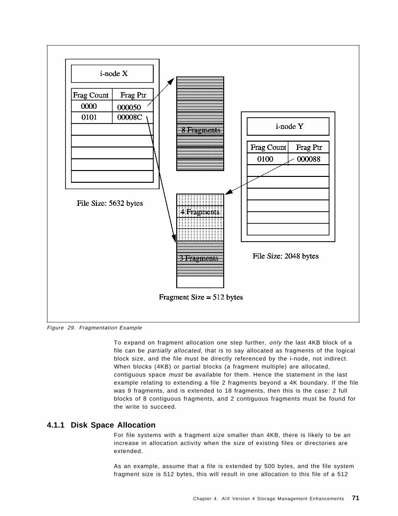
Figure 29. Fragmentation Example
To expand on fragment allocation one step further, only the last 4KB block of afile can be partially allocated, that is to say allocated as fragments of the logicalblock size, and the file must be directly referenced by the i-node, not indirect.When blocks (4KB) or partial blocks (a fragment multiple) are allocated,contiguous space must be available for them. Hence the statement in the lastexample relating to extending a file 2 fragments beyond a 4K boundary. If the filewas 9 fragments, and is extended to 18 fragments, then this is the case: 2 fullblocks of 8 contiguous fragments, and 2 contiguous fragments must be found forthe write to succeed.
4.1.1 Disk Space AllocationFor file systems with a fragment size smaller than 4KB, there is likely to be anincrease in allocation activity when the size of existing files or directories areextended.
As an example, assume that a file is extended by 500 bytes, and the file systemfragment size is 512 bytes, this will result in one allocation to this file of a 512
Chapter 4. AIX Version 4 Storage Management Enhancements 71
byte fragment. If the file is extended by another 500 bytes, another allocation ofa 512 byte fragment will be made to this file. So far, two allocation operationshave already been performed. However, with a file system fragment size of 4KB,the first file extension operation would have involved one allocation to this file ofa 4KB fragment and the second file extension operation would not have resultedin an allocation as there would have been sufficient space from the firstallocation. The number of allocations made in the file system using a 512 bytefragment could have been minimized if the two separate file extensionoperations were performed as one extension of 1024 bytes. Although two 512byte fragments would still be allocated, this would involve only one file systemoperation to complete.
4.1.2 Free Space FragmentationAs has been mentioned, free space fragmentation can occur much more within afile system that uses smaller fragment sizes. To clarify, assume that there is aportion of the disk consisting of 8 contiguous 512 byte fragments and that fourfiles, each 500 bytes in size, have written to these fragments in a non-contiguousmanner. The free disk space within this area of the disk (four 512 bytefragments) are unallocated fragments which also reside in a non-contiguousmanner. A file extension operation which would require 2048 bytes would not beallocated these free fragments as they would have to be contiguous for a singleallocation to succeed.
It is quite possible for a file system using a fragment size smaller than 4KB,particularly 512 bytes, to reach high levels of free space fragmentation.
4.1.3 Fragment Allocation MapThe fragment allocation map, used to hold information about the state of eachfragment for each file system, is held on the disk and in virtual memory. Theuse of smaller fragment sizes in file systems results in an increase in the lengthof these maps and therefore requires more resources to hold.
4.2 CompressionCompression, like fragmentation, is provided for journaled file systems in AIXVersion 4 for the better utilization of available disk space. The disk spacesavings made by using compression on average increase by about a factor oftwo. Unlike the JFS fragment support, which treats logical blocks of files anddirectories less than 32K bytes in size differently to those that are larger, the JFSdata compression support will use the same data compression technique for alllogical blocks of files, irrespective of file size and fragment size. It doeshowever, enforce that the fragments used for the files logical blocks arecontiguous.
The obvious advantage of the use of data compression supplemental tofragmentation, is that there is no restriction to the file size, and so compressionwill be efficient for both small and large files.
AIX Version 4 JFS data compression is supplemental to JFS fragment support,and requires the installation of the data compression software package.
Only regular files and long symbolic links can be compressed in file systemssupporting compression. The fragment sizes supported in a compressed file
72 AIX Storage Management
system are 512, 1024 and 2048 bytes only. A compressed file system cannothave a fragment size of 4KB.
The choice of the fragment size for compressed file systems must be made afterevaluating the size of files to be stored and the amount of compression that isactually achieved. Where high amounts of compression are possible, higher diskspace savings can be achieved by using a small fragment size like 512 bytes.However, at the same time performance will degrade quite substantially.
4.2.1 Implementation of Data CompressionIn AIX Version 4, data is compressed at the level of individual files logical blocks.To compress data in large units (all the logical blocks of a file together forexample), would result in the loss of more available disk space. By individuallycompressing a files logical blocks, random seeks and updates are carried outmuch more rapidly.
After compression of a logical block of a file takes place, the compressed logicalblock is written to disk using only the number of fragments required for it. Aftercompression, it is likely that the data in the files logical block will occupy lessthan 4K bytes of disk space. However, if the data does not compress, then it iswritten to disk in the uncompressed format and allocated the full 4KB ofcontiguous fragments.
When a file or directory′s logical block is first modified, 4KB of disk space areallocated to it to guarantee that the write to disk of that logical block will besuccessful. If this allocation fails, then an appropriate system error message isreturned.
In addition to increased disk I/O activity and free space fragmentation problems,file systems using data compression have the following performanceconsiderations:
1) Degradation in file system usability arising as a direct result of the datacompression/decompression activity. If the time to compress anddecompress data is quite lengthy, it may not always be possible to use acompressed file system, particularly in a busy commercial environmentwhere data needs to be available immediately.
2) All logical blocks in a compressed file system, when modified for the firsttime, will be allocated 4096 bytes of disk space, and this space willsubsequently be reallocated when the logical block is written to disk.Performance costs are therefore associated with this allocation, which doesnot occur in non-compressed file systems.
3) In order to perform data compression, approximately 50 CPU cycles perbyte are required, and about 10 CPU cycles per byte for decompression.Data compression therefore places a load on the processor by increasingthe number of processor cycles.
4.2.2 Compression AlgorithmAn IBM version of the Lempel Zev (LZ) algorithm is used to perform datacompression. The LZ algorithm compresses data by representing the secondand subsequent occurrences of a given string with a pointer, identifying theposition of the first occurrence of the string and its length. At the start of thecompression process the first byte of data is represented as the raw characterusing a pointer-byte pair (0, byte). The algorithm then processes a fixed amount
Chapter 4. AIX Version 4 Storage Management Enhancements 73
of data, say N bytes, for compression. Normally, the value of N is one of 512,1024 or 2048. Every time a string in the N bytes is replicated it is replaced by apointer-length pair as described above. After compression of N bytes of data,the algorithm searches for the string starting at the next unprocessed byte in theN bytes previously compressed. If the longest match found has a length of zeroor one, it represents the first byte in the unprocessed string as a raw characteras mentioned previously. If, on the other hand, the length of the matching stringis greater than one, the compression algorithm will represent the string using apointer-length pair and continue to process a further N bytes of data startingfrom that string.
4.3 Disk StripingAIX allows the placement of logical volumes on a specific area of one or morephysical volumes. For example, the center of the disk may be chosen for theplacement of logical volumes when rapid access to data is required. Eventhough this placement strategy can provide fast access to data, it is stillrestricted by the fact that a disk I/O operation is performed to retrieve each datablock.
In Part 1 of Figure 30 on page 75, the numbered disk blocks for the filerepresent the sequence of the data in the file. To read the entire filesequentially will involve reading each disk block in turn.
74 AIX Storage Management
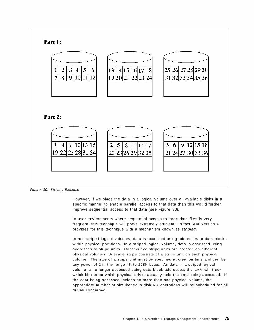
Figure 30. Striping Example
However, if we place the data in a logical volume over all available disks in aspecific manner to enable parallel access to that data then this would furtherimprove sequential access to that data (see Figure 30).
In user environments where sequential access to large data files is veryfrequent, this technique will prove extremely efficient. In fact, AIX Version 4provides for this technique with a mechanism known as striping.
In non-striped logical volumes, data is accessed using addresses to data blockswithin physical partitions. In a striped logical volume, data is accessed usingaddresses to stripe units. Consecutive stripe units are created on differentphysical volumes. A single stripe consists of a stripe unit on each physicalvolume. The size of a stripe unit must be specified at creation time and can beany power of 2 in the range 4K to 128K bytes. As data in a striped logicalvolume is no longer accessed using data block addresses, the LVM will trackwhich blocks on which physical drives actually hold the data being accessed. Ifthe data being accessed resides on more than one physical volume, theappropriate number of simultaneous disk I/O operations will be scheduled for alldrives concerned.
Chapter 4. AIX Version 4 Storage Management Enhancements 75
4.3.1 Usage ImplicationsDisk striping definitely appears to provide very high-performance access to largesequential files. However, to get optimal performance for sequential I/O, thereshould be little or no other I/O activity on the physical volumes.
To make the most efficient use of striped logical volumes, some operatingsystem parameters must be tuned and application requirements for memorymust also be minimized. Results of a benchmark comparing the relativeperformance of striped logical volumes against non-striped logical volumes areprovided in section 8.5.1.3, “Benchmark Results for an I/O Bound Test UsingStriping” on page 272.
The constraints imposed by striping of logical volumes are:
• For striping to be possible, at least two physical volumes are required.
• Mirroring is not possible. Increased I/O activity resulting from mirror-writeswould impact performance.
4.4 Using Page Space for System DumpsA collection of one or more logical volumes, used solely for providing amechanism for storing data temporarily not required to be in real memory, isknown as Paging Space. A description of how paging actually works can befound in 3.1.1, “Page Space” on page 47. Unlike non-paging logical volumes,which are used to store data permanently when a computer is powered on orrebooted, there is no guarantee that data which previously resided in pagingspace would still remain there.
In AIX Version 4, paging space is additionally used as a primary dump device forsystem dumps. During installation of AIX Version 4, /dev/hd6, (the paging logicalvolume), is automatically configured as the primary dump device. However, forAIX systems being migrated to AIX Version 4, /dev/hd7 is still being maintainedas the primary dump device.
After a system dump to the paging space (primary dump device) has takenplace, the system boot process has to move the dump data from this area to anappropriate area on the disk. This has to be carried out since the paging spacewill become re-activated and all data previously residing there is likely tobecome over-written. By default, the dump is copied to the directory/var/adm/ras. The sysdumpdev command now has an optional flag which can beused to specify a different directory for the dump to be copied to.
The advantages of using paging space for the primary dump device are:
1. It makes better util ization of storage space by using an existing logicalvolume as opposed to reserving one specifically for this purpose. Adedicated dump device like /dev/hd7, as used in AIX Version 3, can be quitewasteful, particularly within a stable system.
2. Since paging space is normally configured to be of the same size or largerthan RAM this would guarantee that it is has sufficient space for a dump.
3. The I/O operations, particularly when writ ing dump data to disk, areimproved if the paging logical volumes are strategically placed for fastaccess to data. For example, at the center of the disk and also over asmany physical volumes within the volume group as possible.
76 AIX Storage Management
4.5 Variable I-nodesIn all UNIX implementations, when a file system is created, several datastructures known as i-nodes are written to the disk. For each file or directoryone such data structure is used which describes information pertaining to it. Thesort of information which is stored in the i-node includes file type, permissions,size, user and group owner ids. Other critical pieces of information that are heldin the i-node are the disk addresses at which the files data is stored.
AIX, like other UNIX implementations, reserves a number of i-nodes for files anddirectories in each file system that is created. In releases prior to AIX Version 4,an i-node is generated for every 4KB of disk space that is allocated to the filesystem being created.
In a 4MB file system this would result in 1024 i-nodes being generated. Forearlier releases this figure would probably suffice, since a file or directory isallocated at minimum 4KB of disk space anyway. In AIX Version 4, since diskspace is allocated in fragments allowing better utilization of disk space 1024i-nodes in a 4MB file system can quickly become exhausted if a large number ofsmall files are written (assuming a fragment size of 512 bytes). In a file systemcreated using a 512 byte fragment size, 8192 files, at maximum, can be written ifthe largest file size is 512 bytes.
AIX Version 4 JFS provides a parameter to tune the number of i-nodes generatedat file system creation time. This parameter, better known asnumber-of-bytes-per-i-node (NBPI), can be any power of 2 in the range 512through 16384 (examples include 512, 1024, 2048, 4096).
When NBPI is used in conjunction with the fragment size it can allow betterstorage management, particularly when it is known beforehand the number andsize of files to be stored in the file system. See 3.1.4, “File Systems” on page 58for more information on i-nodes.
4.6 File System Maximum Size IncreaseIn releases of AIX prior to Version 4, the maximum size a journaled file systemor logical volume can grow to is 2GB. The limitation is due to the usage of a 32bit signed integer value giving maximum file system addressability of 2GB: 2raised to the power of 31, the most significant bit giving the sign. With thegrowing needs of commercial and scientific environments, this limit can bereached quite quickly. In fact it is now becoming more commonplace fordatabase application environments to need to access larger volumes of data.
In AIX Version 4, the maximum size a journaled file system or logical volumecan grow to is 256GB. This is now possible since a 64 bit variable is used as forthe pointer.
However, note that the maximum file size is still limited to 2GB. This is becauseno change has been implemented to the i-node structures used to reference thedata blocks. See 3.1.4, “File Systems” on page 58 for more information on filesystems.
Chapter 4. AIX Version 4 Storage Management Enhancements 77
4.6.1 JFS Log ConsiderationsFor journaled file systems, a transaction log is maintained which provides filesystem recovery in case the system abnormally terminates. One JFS log, with adefault size of one logical partition, maintains log data for all the file systemswithin a volume group. For file systems that are no larger than 2GB, the defaultlog size is sufficient. However, for file systems that are larger than 2GB, it maybe necessary for the log size to be increased proportionately.
4.7 SummaryThis chapter covers the latest enhancements to storage management madeavailable in AIX Version 4. These enhancements include:
• Fragmentation
The basic unit of file system allocation is now the fragment, which can be512, 1024, 2048, or 4096 bytes.
• Compression
The JFS now supports compression which can result in a space saving of afactor of 2.
• Striping
The logical volume manager now support striping which can radicallyimprove performance.
• Page Space for System Dumps
Page space can now be allocated as a dump device.
• Variable i-nodes
The number of i-nodes created within a file system can now be variedallowing for improved management of disk resources.
• File System Size Increase
The maximum file system size is no longer limited to 2GB.
78 AIX Storage Management
Chapter 5. Storage Subsystem Design
This chapter covers the issues and considerations involved in designing storagesubsystems. Guidance on actually implementing the ideas set out here can befound in Chapter 6, “General AIX Storage Management” on page 95, andChapter 8, “Practical Examples” on page 185.
5.1 IntroductionDesigning storage subsystems involves evaluating the requirements that thebusiness processes that will be executed on the machine have, in terms of dataaccess and availability. Systems will generally be used for more than onepurpose (database applications may compete for resource with word processingand image based applications for example), and it is important to attempt toconfigure the environment in such a way that each process can perform withinrequired tolerances (these are usually performance and availability related -user response time, and recovery in the event of error or failure for example). Aseach process will have differing requirements, this task will of necessity involvesome compromise. The design of the AIX storage management components, ashas been covered in Chapter 3, “Operating System Software Components” onpage 47, does allow great flexibility in organization. The logical volume managerallows the physical disks to be partitioned and the space thus created organizedin different ways to enable performance requirements to be met in one logicalvolume, and availability requirements in another for example.
The first task is therefore to evaluate the storage requirements of the applicationset that will be executed on the system in terms of:
1. Performance requirements
2. Availability requirements
3. Recovery requirements
4. Disk utilization
Each of these areas will now be examined in more detail.
5.2 Planning Disk UtilizationThe design of the volume group and logical volume organization has a majorimpact upon performance, availability, and recovery. The first consideration inthe process is volume group allocation.
5.2.1 Volume GroupsThe most common hardware failure in a storage subsystem is disk failure,followed by failure of adapters and power supplies. When failures of this typeoccur, recovery will be easier if a sensible volume group design has beenimplemented. Multiple volume groups should generally be implemented for thefollowing reasons:
• Maintenance
Copyright IBM Corp. 1994 79
− Maintaining only operating system information in the root volume groupis a good decision because operating system updates, reinstallations,and crash recoveries can be effected without danger to user data.
− System updates or reinstallation generally only affect the root volumegroup, so these regular and important processes can occur more quickly,as only operating system or application data is included in the changes.
• Physical Partition Size
All physical volumes within a volume group must have the same physicalpartition size. In some cases greater granularity may be required inallocation of physical partitions to logical volumes, and the only way toimplement this is to place those logical volume with differing physicalpartition requirements into separate volume groups. An example of whenthis might be necessary would be an environment where many small logicalvolumes need to be created for specialized file systems of a size that mayentail much wasted space with 4MB partitions (2MB file systems say). Thegreater flexibility afforded by the smaller partition is offset by increasedperformance overhead to the LVM.
• Quorum Characteristics
If there is a requirement for implementing a file system in a non-quorumvolume group, then a separate volume group that does not utilize quorumchecking needs to be created.
• Security
In order to allow important confidential data to be removed and stored in asecure place when required, a volume group including physical volumes onremovable disks should be created. At night, for example, the volume groupcan be exported and the disks with the sensitive data removed and kept in asecure place.
• Multiple JFS Logs
In order to reduce bottlenecks in a volume group with many journaled filesystems, multiple JFS logs may be required.
• Switching Physical Volumes Between Systems
In some cases there may be a requirement to share a physical volumebetween systems, for availability or shared access for example. If thephysical volumes so utilized are maintained in a separate volume group,then this volume group can be exported and varied off line for reuse on asecond system (import, vary on), without interrupting the normal operation ofeither system.
The number of volume groups created should therefore be decided based uponconsideration of these points.
5.2.2 Physical VolumesThe next consideration should be the number of physical volumes per volumegroup. This affects quorum checking and mirroring. A volume group with twodisks and quorum checking will fail to vary on if the disk with two VGDAs fails(see “Quorum Checking” on page 55 for a description of this process). Withmore than two disks, 51% or more of the VGDAs must become unavailable forthe vary on to fail, and data to become inaccessible. This is particularly true in atwo disk mirrored system, failure of the two VGDA disk will result in no access,even though a good copy of the data is still available.
80 AIX Storage Management
Enough physical disks must also be included to support the mirroring strategyrequired, both in terms of space for the mirrored copies, and number of disks forthe policies. If mirroring is to be done across the maximum number of physicalvolumes possible, for availability purposes, then it makes sense to have at leastenough space to ensure the copies are stored on separate physical volumes. Adisk failure in this scenario will not impact access to the data.
5.2.3 Logical VolumesThe delineating factors for deciding upon the number of logical volumes tocreate are basically performance and availability. As many logical volumesshould be created as there are different performance and availabilityrequirements. The design of the logical volumes themselves to satisfy theserequirements is covered in 5.3, “Planning for Performance” on page 82, and 5.4,“Planning for Availability” on page 86. Within this however, there is theconsideration of disk space utilization. Depending upon the intended purpose offile systems that will be created within logical volumes, different fragment sizesmay be required to optimally utilize the available disk space in the logicalvolumes. As has been described in 4.1, “Fragmentation” on page 69, choosingdifferent fragment sizes can significantly improve disk space use. If there is aneed for file systems containing many small files, then a logical volume for eachfile system with different requirements should be created.
5.2.4 File SystemsThe primary considerations when creating file systems are as follows:
• Fragment size
Fragment size should be considered only if there will be many files in the filesystem less than 32KB in size, or compression will be used. In the formercase, the fragment size should be selected based upon the average size ofthe files, in order to minimize wasted space. For example, file less than 512bytes or that will grow in chunks less than 512 bytes would be moreeconomically stored in a file system with a fragment size of 512.Compression is discussed later in this section. This is an AIX Version 4facility.
• Number of bytes per i-node (NBPI)
The number of bytes per i-node is described in 4.5, “Variable I-nodes” onpage 77. This parameter controls the number of i-nodes created in the filesystem. The main consideration will be the number of expected files; if onlya few large files will be stored, then increase the NBPI to reduce the numberof i-nodes created, and hence free up disk resource that would have be usedby the extra i-nodes. The NBPI and fragment size together directly affect themaximum possible size of the file system, and this is therefore a furtherconsideration. File system size is discussed later in this section. This is anAIX Version 4 facility.
• Compression
Compression is discussed in 4.2, “Compression” on page 72. If disk space isat a premium, and performance is not the major issue, then file systemcompression should be considered. Using compression can reduce theamount of storage space required by files enormously, at the cost of theoverhead required for the compression. The algorithm is performed on afragment basis, and its effectiveness is dependent upon the type ofinformation contained in the file. Larger fragment sizes will help to offset the
Chapter 5. Storage Subsystem Design 81
performance overhead, by reducing the number of allocation requests andphysical I/O. This is an AIX Version 4 facility.
• File system size
The size of the file system should be chosen to be large enough toaccommodate the required files. It is better to err on the small side, as filesystems can be easily expanded as the limit approaches, while reducing(which can be done) is more work. Recovering free space within file systemslost due to fragmentation can be accomplished using the defragfs commandwhich is discussed in Chapter 7, “Storage Management Files andCommands Summary” on page 139.
Having created volume groups and added the required number of physicalvolumes, the logical volumes and file systems need to be created. There are twobasic considerations: performance and availability. Generally, designing for highperformance will impact availability, and vice versa. The next two sections lookat design from these perspectives.
5.3 Planning for PerformanceThe performance of a disk subsystem is a combination of factors that includes:
• Adapters
This includes the physical performance capabilities of the adapter, as well asthe organization of devices using the adapter. In order to maximizeperformance to high speed disk devices on an adapter, the characteristics ofthe adapter should be considered. For example, SCSI adapters can supportmultiple devices operating in either synchronous or asynchronous modes(see 2.2.1.1, “Small Computer System Interface Adapter” on page 23 forinformation on SCSI technology). To achieve maximum throughput for asynchronous disk device, only other synchronous devices should be attachedto the adapter, and the total bandwidth (or throughput) of these devicesshould not exceed the capabilities of the adapter itself.
The same considerations apply to adapters of other types. If multiple devicesare supported on the adapter, the total bandwidth available should not beexceeded.
Finally, obviously the fastest adapter that meets the environmentalrequirements of the site (in terms of cable lengths, and devices supported)should be selected to maximize performance. Other functions like commandtag queuing (for some SCSI adapters), and differential communications (toreduce errors) will also improve performance.
• Physical disk devices
Physical disk drives themselves support different levels of function in theirhardware. Some drives support bad block relocation and elevator seekfunctions internally for example (see 2.2.2, “Disk Storage” on page 25 for adiscussion of disk technology). Off-loading these functions from the LVM willincrease performance.
Some subsystems, such as the 7135, support striping within the subsystem(RAID 0) which will also increase performance.
Again, selecting disks with the fastest overall read/write performance figuresshould be the policy for maximizing performance.
• Logical Volume Manager
82 AIX Storage Management
Selecting the highest performance hardware goes a long way to maximizingthe performance of a disk subsystem, but the software implementation interms of data placement on the disks and access methods (random orsequential) are also vital to the overall result.
Under AIX Version 4, the LVM supports striping, which means that the logicalpartitions of a logical volume can be spread across multiple disks andtherefore accessed concurrently (see 4.3, “Disk Striping” on page 74 for adiscussion of striping). Striping will maximize performance for sequentialreads and writes, where the LVM can schedule consecutive reads and writessimultaneously to blocks on different disks. Performance will be furtherenhanced when the disks are on different adapters, thereby allowing fullconcurrency. Setting up striping is discussed in 8.5.1, “Striped LogicalVolumes” on page 268.
Whether striping is to be used or not, the placement of the data on the disksurface itself affects the performance of the subsystem. The LVM provides anumber of parameters at logical volume setup that govern the policies it willenforce in terms of data placement and access. These policies are explainedin “Logical Volume Manager Policies” on page 55. In order to maximizeperformance, the following policies should be adopted:
− Intra-physical volume allocation policy
For maximum performance logical partitions should be selected in thecenter of the disk.
− Inter-physical volume allocation policy
For maximum performance the maximum number of physical volumesavailable should be used for the logical volumes logical partitions. Thiswill allow the LVM to schedule requests for long sequential reads orwrites across physical disks in parallel.
− Mirroring
Mirroring should generally be disabled for maximum performance. If it isrequired however, then the scheduling policy should be set to paralleland the allocation policy to strict. This will cause the LVM to place copieson separate physical volumes, and to perform writes in parallel, therebymaximizing performance. In addition, reads will be scheduled to the copyof the data required that is closest to a disk head, improving readperformance. Write verification and mirror write consistency should alsobe set to no. This will prevent the LVM from wasting a disk revolution onevery write to read back the data for validity, and also stop the LVMwaiting for all writes to copies to succeed before returning successfulcompletion of the write.
Adopting these policy settings in the LVM will maximize performance, but atthe expense of availability. If availability is an equally great issue, thencompromises will be necessary, such as using mirroring with reducedefficacy (as described in this section).
• File System
With regard to maximizing performance from the file system point of view,there are several configuration options that can be taken at file systemcreation time:
− Fragment size
Chapter 5. Storage Subsystem Design 83
Using the largest fragment size of 4096KB will minimize allocationoperations and maximize throughput from the file system. This could beat the expense of space utilization within the file system, depending uponthe sizes of files within (see 5.2, “Planning Disk Utilization” on page 79for a discussion of maximizing disk space utilization).
− Compression
Using compression increases the overheads of reads and writes to thefile system, and therefore to maximize performance, compression shouldnot be used.
− Log devices
If many file systems are using the same log device, then this canintroduce a bottleneck. Reducing the number of file systems that will beconcurrently accessing a log device will avoid this problem. In order todo this, multiple log devices should be created within the volume group.To maximize performance, the log device should be on a differentphysical volume, and preferably a different adapter to the file systemssharing the log.
The JFS uses 4KB buffers for reading and writing, and returns success to arequesting application on receipt of the data. The actual physical write is notdone until the buffer is full. This means that just using the JFS can improvedisk I/O performance.
Warning
Some applications (some databases for example), rely on the fact thatwhen a write is requested, it is actually done immediately. In thesecases, using the JFS may speed up performance, but can introduceinconsistencies if a crash should occur before a write actually took place- the database logs would be out of sync with the JFS logs, resulting inan inconsistent state. These type of applications should write directly to alogical volume. For ordinary applications this would not be the case, andrecovery to a stable state should be possible from replaying the JFS log.In all cases, checking with the application provider makes good sense.
Fragmentation of the file system will have an adverse effect on I/Operformance as it will increase the number of seeks required to accessinformation. The smaller the fragment size selected, the worse this problemcan become. Regular defragmentation of the file system, will alleviate thisproblem, and is can be accomplished using the defragfs command,discussed in Chapter 7, “Storage Management Files and CommandsSummary” on page 139.
• Operating System Parameters
There are a number of operating system parameters that affect theperformance of I/O subsystems. These parameters should be adjusted withcaution as they have system wide scope; this means that though they mayradically improve performance for one application using one logical volume,they may have a detrimental effect on others:
− Sequential Read Ahead
This is a Virtual Memory Manager feature that allows the VMM to read inpages of information from disk before they are required. If the VMMsuspects that a large sequential read is about to take place, it will usethe values set in minpgahead and maxpgahead to decide on how many
84 AIX Storage Management
extra pages ahead of the current one to read in. This means that whenrequests for subsequent pages arrive, the required pages are already inmemory and time is saved. More detail on the setting of theseparameters is available in the InfoExplorer section Tuning SequentialRead Ahead.
− Disk I/O Pacing
This feature is intended to prevent those programs that generate verylarge amounts of I/O from saturating the I/O queues with requests, andthereby causing the response time of less demanding applications todeteriorate. Disk I/O pacing enforces high and low water mark values onthe number of I/O requests that can be outstanding for any memorysegment (this effectively means for any file). When the number ofoutstanding I/O requests for a segment reaches the high water mark, theprocess making the requests is put to sleep until the number of requestshas reached the low water mark.
This feature is set to off by default. See the InfoExplorer article on Use ofDisk-I/O Pacing for further details on tuning these parameters.
− SCSI Device Driver max_coalesce Parameter
When there are multiple requests in a SCSI device drivers queue, itattempts to coalesce these requests into a smaller number of largerrequests. The largest request size (in terms of data actually transmitted)that the device driver will build, is limited by the max_coalesceparameter. See the InfoExplorer section on Modifying the SCSI DeviceDriver max_coalesce Parameter for details on adjusting this setting.
− Setting SCSI Adapter and Disk Device Queue Limits
It is possible to enforce a limit on the maximum number of outstandingrequests on a queue for a given SCSI bus or disk drive. Setting theseparameters can improve performance for those devices that do notprovide sophisticated queue handling algorithms. See the InfoExplorersection on Setting the SCSI-Adapter and Disk-Device Queue Limits forfurther information on adjusting these parameters.
− Controlling the Number of System pbufs
The LVM uses a construct called a pbuf to control pending disk I/O. InAIX Version 3, a pbuf is required for each page being read or written,which for applications with heavy I/O can result in pbuf pool depletion. InAIX Version 4, a pbuf is used for every sequential I/O request, regardlessof the number of pages involved, thereby reducing the load on the pbufpool. It is possible to tune the number of pbufs available, and in somecases this can improve performance. See the section in InfoExplorer onControlling the Number of System pbufs, for further information.
• Applications
The final performance considerations are at the actual application level. Thedesign of the application can have a major effect upon performance. It is notalways possible to affect the way in which application operate, but on thoseoccasions where it is, the following considerations should be taken intoaccount:
− Asynchronous Disk I/O
Applications can use asynchronous disk I/O, which means that controlreturns to the application from the read/write as soon as the request has
Chapter 5. Storage Subsystem Design 85
been queued. The application can then continue working while thephysical disk operation takes place. Obviously not all applications will beable to take advantage of this feature, but for those that can, theperformance benefits are significant. More information on this featurecan be found in InfoExplorer in the section on Performance Implicationsof Asynchronous Disk I/O.
− sync and fsync
In a similar fashion to asynchronous disk I/O, the sync() system callschedules a write of all modified memory data pages to disk, but returnsimmediately. Conversely, the fsync() call will not return until the writingis complete. Those application which must know whether the write wassuccessful will not be able to take advantage of this, but for those thatcan, again the performance benefits can be significant. For moreinformation, see the InfoExplorer section on Performance Implications ofsync/fsync.
Examples of using LVM and file system configuration commands to maximizeperformance are detailed in 8.3.4, “A Design Example for ImprovedPerformance” on page 218.
5.4 Planning for AvailabilityDesigning a disk subsystem for availability also involves a number ofconsiderations, including:
• Adapters
From an availability standpoint, it is better to design a storage system usingmore rather than less adapters. This is really of benefit in the case wheremirroring is to be used; having mirrored copies on separate adapters meansthat failure of one adapter will still leave the information accessible from thecopy on the other adapter.
• Redundancy
Redundancy is one of the most important mechanisms for ensuringavailability. This entails having backups for all vital system components inmuch the same way as multiple adapters and mirroring above; withinstorage subsystem components, this really means having backup powersupplies, cooling fans, adapters, data paths, and spare disk drives that canbe automatically switched in when required, with no service or informationloss.
At a pure operating system level, redundancy is limited to mirroring andmultiple adapters. Much greater availability guarantees can be achievedusing the features of external devices providing many of the backup featuresdiscussed. Devices available that support these kinds of features include theIBM 7135 and the 9570. Details of these and other similar devices can befound in A.2, “Disk Storage Products” on page 326.
• RAID
This set of performance and availability features is discussed in 2.2.2.2,“Selecting the Correct Disk Storage Devices” on page 27. RAID levels 1, 3,and 5 provide increasing levels of high availability and performance externalto the operating system. The attached subsystem performs all of the RAIDfunctionality under the covers, and presents an ordinary disk drive interface
86 AIX Storage Management
to the operating system. Subsystems which support RAID to varying degreesinclude the IBM 7135, IBM 3514, and IBM 9570. A brief discussion of theseand other devices can be found in A.2, “Disk Storage Products” on page 326.
• Logical Volume Manager
As in the case of performance, there are several options that can be taken atlogical volume creation time to maximize availability of data. These optionsinclude policies governing the placement of data on the physical disks andmirroring. Data can be divided into two categories, operating system data,and user data, and the mirroring setup is slightly different for each case:
− Mirroring the root volume group
This procedure will maximize availability of the operating system. Atleast three physical disks should be in the rootvg to ensure that aquorum will always be available in the event of a single disk failure.
Note
A full system backup should be taken before performing any diskreorganization procedures.
Mirroring the root volume group involves setting up one or two copies ofeach logical volume in the volume group; the procedure for actuallyimplementing this is explained in 8.2, “rootvg Mirroring - Implementationand Recovery” on page 187.
Warning
The mirrored copies must each be on a bootable physical volume orelse a failure in the main bootable copy will not be easilyrecoverable. The boot logical volume should not be mirrored, as thiscan cause problems, rather a new boot logical volume should becreated on each physical disk containing a mirror copy.
The Non-Volatile RAM must be updated to reflect the new disks availableas boot devices, so that in the event of failure of the main copy of therootvg, a reboot can be effected from another copy.
− Mirroring user data
Mirroring user data also involves creating copies of all of those logicalvolumes requiring high availability. For maximum availability, thefollowing policies should be selected:
- Number of mirrored copies
The number of copies of a logical volume maintained by the LVM canbe one, two, or three. Maximum protection against failure is providedusing three copies, though at increased overhead. Again, availabilityis mainly achieved at the cost of performance, though this willdepend on the intended usage of the mirrored logical volume. If thevolume will mainly be used for reading, then performance can beenhanced, as the LVM will schedule reads to the disk head closest tothe required data.
- Inter-physical allocation policy
Having the logical partitions comprising the mirrored logical volumespread across the minimum number of disks will optimizeavailability. Ideally, each copy should be on a separate physical
Chapter 5. Storage Subsystem Design 87
volume which is itself on a separate adapter. To enable this, therange parameter should be set to minimum, and the strict parameterto yes; this will force the LVM to restrict each copy of the logicalvolume to as few disks as possible, and to maintain the copiesseparate (no copy may share a disk). Prior planning to ensure spaceon the physical disks to hold the entire logical volume will ensureeach copy can be successfully kept on a single physical volume.
- Intra-physical allocation policy
The actual location of the data on each physical disk will have nodirect impact on availability. If however, a center policy is selectedfor example, then although the LVM will try and fulfill the request onall of the mirrored copies, the inter-disk allocation policy will takepreference. This means essentially, that if there are not enoughcenter located logical partitions on a disk, then rather than look atspreading the logical volume to another disk, edge or middle locatedpartitions will be used instead.
- Scheduling policy
For maximum availability, a sequential policy should be adopted.This means that writes will be scheduled one after the other to allcopies of the logical volume, each write having to complete beforethe next occurs. This maximizes the chances of at least one copysurviving in the event of a system crash during the process.
- Write verification
This feature should be switched on for maximum availability. Writeverification means that after every write to a disk, the data written isread back to ensure its validity. This does have performanceimplications as every write will involve one extra disk revolution forthe read verify.
• File System
Using the JFS provides some availability features over writing to raw logicalvolumes, or using NFS for example. The JFS records all changes to themeta-data of a file system into a log (file systems are explained in 3.1.4, “FileSystems” on page 58). If there should be a system crash, on reboot, the logis replayed and the file system returned to its last consistent state. Thisprevents corruption of the file system and thereby assists in maintaininghigher availability.
• Application
Applications themselves can be designed to be availability aware. In thereverse of the requirements for high performance, applications should avoidasynchronous I/O to ensure that any data written is committed to disk beforecontinuing and risking inconsistencies. In addition, the fsync() system callshould be used rather than sync(), so that the application can be sure that allmodified pages in memory have been written before continuing.
The section on application oriented performance considerations earlier inthis section gives more details on these operating system calls.
88 AIX Storage Management
5.5 Planning Backup StrategiesThe rest of this chapter looks at backup strategies, and the elements involved inplanning them.
5.5.1 Backup OverviewAs soon as the system has been set up and the operating environmentconfigured as required, a backup strategy should be immediately implemented.From this point on, valuable data will be created and stored within the storagesubsystem that represents time and effort, and in most cases that supports thebusiness. The organization of the system (operating system data andapplications), and the user information created (files and directories) are subjectto misadventure, however carefully managed; files can be accidentally erased,and hardware or software faults can destroy some information or even the entiresystem. For these reasons, it is important to be able to recover the system backto a point at which work can continue. Backing up the system involves makingcopies of all the information contained in it on a some medium that can bestored separately. The copies can then be used to recreate the system after afailure has been repaired, or information accidentally lost. The information in thesystem is usually highly dynamic, and therefore frequent copies or updates tothe copies (also known as incremental backups) should be taken. The frequencyand content of the updates or full backups is unique for each business, anddepends upon the rate of change of information and the relative importance ofthat information. Evaluating this is the process of developing a backup strategy.The following points should be considered:
• Ensure recovery from major losses
Consider every potential catastrophe, however unlikely, and determinewhether recovery would be possible. If the backup media was lost in somenatural disaster, would recovery be possible? Obviously, it is necessary tofactor in the likelihood of a particular disaster, but this must be done inconjunction with consideration of the value of the data. It′s not much comfortto reflect how unlikely the ball of lightning that destroyed the backup mediainside a safe was, when the business is ruined as a result.
• Check backups periodically
There are many different types of backup media, each with varying degreesof reliability and longevity (see 2.2.3, “Tape Storage” on page 34 for acomparison of backup media). Check the condition of backups on a regularbasis to ensure that they are still usable.
• Keep old backups
Although it is a good policy to develop a regular cycle for reusing backupmedia, complete copies should be maintained for some time as it can oftenbe a while before it is noticed that a particular file is damaged or unusable,by which time the backup copies may contain copies of the damage. It istherefore a good plan to implement a recycling policy such as the following:
− Recycle all media except Friday backups weekly
− Recycle all Friday media except the last in the month monthly
− Recycle all monthly media except the last in the quarter quarterly
Keep the quarterly backups indefinitely. This will always ensure the ability toaccess information up to three months old at various levels of currency.
Chapter 5. Storage Subsystem Design 89
• Check file systems before backing up
Making a backup of a damaged file system will result in the ability to restorethat damaged file system in the event of failure. It is therefore a good idea tocheck file systems before backing up to ensure integrity.
• Ensure files are not in use during backup
Files that are in use during a backup will be different to the backed up copy.Backups should therefore be taken while the system, or files being backedup, are not in use.
• Backup the system before implementing any major changes
Major changes introduce the possibility of errors and hence loss of data. It isalways sensible to take a backup prior to any such activity.
5.5.2 Backup PlanningThere are two main types of backup:
• Complete system backup
In a complete system backup, a copy is made of everything on the system.this can then be used to completely restore the system in the event of afailure. The complete backup can contain operating system and user data,although it is more sensible to maintain these two separately for thefollowing reasons:
1. User data changes more regularly than system data, and the backup wil lbe smaller if the two are kept separate.
2. It is quicker and easier to restore user data when kept separate from theoperating system. Crashes only affecting the operating system, onlyrequire the operating system backup to be restored, and vice versa.
• Incremental backup
In an incremental backup, only the data that has changed since the lastbackup is backed up.
A complete system backup policy should be used when data does not changetoo often. The backups should be scheduled at a frequency that allows completerecovery of business critical information. For example, if database update runsare done weekly, then a backup after the run each week is sensible.
An incremental policy should be used when information is extremely dynamic.Full system backups are taken at a fixed interval, within which backups ofchanged information are taken at shorter intervals. The frequency of theincremental backups depends upon the criticality of the information, as in thecomplete system backup policy. The frequency of the incremental backupsdepend upon the volumes of data that have changed. As recovery withincremental backup requires reloading the last full backup followed byapplication of the incremental backups up until the point of failure, the frequencyof incremental backups should be set at a value which is a balance betweencriticality of information and number of incremental backups that will needapplying.
90 AIX Storage Management
5.5.3 Backup MethodsThere are several ways of backing up information:
• Backing up by name
This method is also called file name archive, and should be used to backupindividual files or directories, if required. This mechanism is most commonlyused by users to make backups of their own files.
• Back up by file system
This method is also known as backup by i-node, and is used to backup entirefile systems. This mechanism should be used by the system administrator toback up large groups of files. It is also used for incremental backups.
• Backup by volume group
This method allows complete volume groups to be backed up. There areseparate commands for the root volume group and for user volume groups.
The following commands can be used to implement the backup policy created:
backup This command allows backup by file name or by file system.
mksysb This command creates an installable image of the root volume group.
savevg This command backs up a user volume group.
cpio This command copies files into and out of archive storage. The cpioformat is common across many platforms, and so can be used forexchange of information between systems.
dd This command will convert and copy information from one device toanother. The dd command does not group multiple files in anyparticular format, it just streams the data, performing any supportedconversion from the source to the target device.
tar This command manipulates archives of files and directories. The tarcommand will create an archive on the output device, write files anddirectories to it, and extract them when required.
rdump This command backs up files by file system to a device on a remotemachine.
pax This POSIX conformant command will read and write tar and cpiocompliant archives.
These commands are described in detail in Chapter 7, “Storage ManagementFiles and Commands Summary” on page 139. Examples of backing up a systemare detailed in 8.4, “Managing Backup and Restore” on page 244.
5.5.4 Backup MediaSo far, backup purposes, policies, and commands have been discussed. Thisleaves the important topic of the actual media that the backup will be stored on.Tape devices are the most common backup or long term archive medium,though there are still several considerations:
• Device Technology
This should be governed by the requirements below, but is more often just aquestion of cost per megabyte. The most important factors should be thereliability, longevity, performance and capacity.
Chapter 5. Storage Subsystem Design 91
Volume of information should be considered too, as this might suggest atape library. Short term archive may suggest an optical device. Thesedecisions are covered in 2.1, “Selecting the Hardware Components” onpage 17.
• Performance
It is important to consider the length of time that a backup will require, andthis is a function of the volume of data and the speed with which the devicecan write it. If backups need to be taken every evening, then a devicecapable of completing the process in the time available should be chosen.
• Capacity
This is a question of cost, storage space, and ease of use. The moreinformation that can be packed onto the media, the better generally, as thismeans that less media will be required for backups. Storage space istherefore less, and if a single cartridge is sufficient, no operator interventionmay be required. If multiple cartridges will be required, and operatorintervention is not possible, then a tape library should be considered.
• Longevity
As was mentioned earlier in this section, the length of time that the mediacan be safely stored is important. This governs not only the backup cycles,but for how long the media can be safely reused.
• Reliability
This is a very important issue. Although checks on the success of a backupcan and should be performed, unreliable devices that have a highpercentage of errors, and produce occasional unreadable backups, are timeconsuming and dangerous. Some devices encounter read back problems too,even though the media copy may be good.
• Compatibil ity
Device technology improves and changes with time. It is a good idea toensure that next generation of devices support existing archive and backupmedia.
These considerations are discussed in relation to tape technology in 2.2.3, “TapeStorage” on page 34.
5.6 SummaryThis chapter has looked in detail at the planning and design requirements forstorage subsystems. Design of the subsystem involves considering the followingpoints:
1. Disk Utilization
How the physical subsystem will be organized from the perspective of:
• Volume Groups
• Physical Volumes
• Logical Volumes
• File Systems
2. Performance
92 AIX Storage Management
For those applications that require high performance, designing the storagesubsystem for maximum performance. This involves optimizing:
• Adapter performance and function
• Physical disk device performance and function
• Optimizing the Logical Volume Manager for performance
• Optimizing file systems for performance
• Optimizing operating system parameters for performance
• Optimizing application design for performance
3. Availability
For those applications that require high availability, designing the storagesubsystem for maximum availability. This involves optimizing:
• Adapter and disk organization
• Implementing redundancy
• Possible use of RAID
• Optimizing the Logical Volume Manager for availability
• Using the JFS if possible
• Optimizing application design for availability
4. Backup
Designing a strategy that allows for as full a recovery as necessary in theevent of failure, for the business to continue. This entails the following:
• Considering all possible failure scenarios and designing a strategy tocope with them
• Selecting the appropriate backup type
• Selecting the relevant backup commands to use
• Selecting the appropriate devices
Chapter 5. Storage Subsystem Design 93

94 AIX Storage Management
Chapter 6. General AIX Storage Management
This chapter will explore Storage Management from a more practical aspect.Much of the functionality available with Version 3 is still included in Version 4, sothis chapter will provide useful information for Storage Management at eitherrelease.
6.1 IntroductionThe purpose of this chapter is to provide the reader with information, which it ishoped will prove useful for applying the basic concepts of storage managementinto their business environment. The areas which will be covered will includethe management of physical storage devices, volume groups and logicalvolumes using the Logical Volume Manager (LVM) functions provided in AIX.Consideration will also be given to issues relating to performance, availabilityand the capability of backing up and restoring.
6.2 Managing Physical VolumesManagement of physical volumes involves day-to-day activities that not onlyensure that they are installed and configured correctly, but also that they aremaintained in a correct operating environment and monitored regularly so thatdisasters from physical volume failures are prevented, by taking precautionarysteps.
For a physical volume to be used for storage purposes, either by the LVM ordirectly via a low-level interface, it must first be recognized by the system andconfigured to be in an available state. This can be done fairly quickly and withease, using the AIX Systems Management Interface Tool (SMIT). Oncerecognized by the system it can then be included in a volume group and alogical volume or a journaled file system can then be created on it, providingusers the ability to store data in it.
When a RISC System/6000* computer system is powered on or rebooted, the AIXoperating system will attempt to configure all devices physically connected to it.Some devices may be attached while the system is up, and these can normallybe configured using the cfgmgr command, or by using SMIT. The fact that aphysical volume is configured and known to the system does not mean that it isready to be used for storage purposes.
This section will attempt to describe only those areas specifically relating tophysical volumes. This will include:
• Configuring physical volumes
• Modifying physical volume characteristics
• Removing physical volumes
• Monitoring physical volumes
Copyright IBM Corp. 1994 95
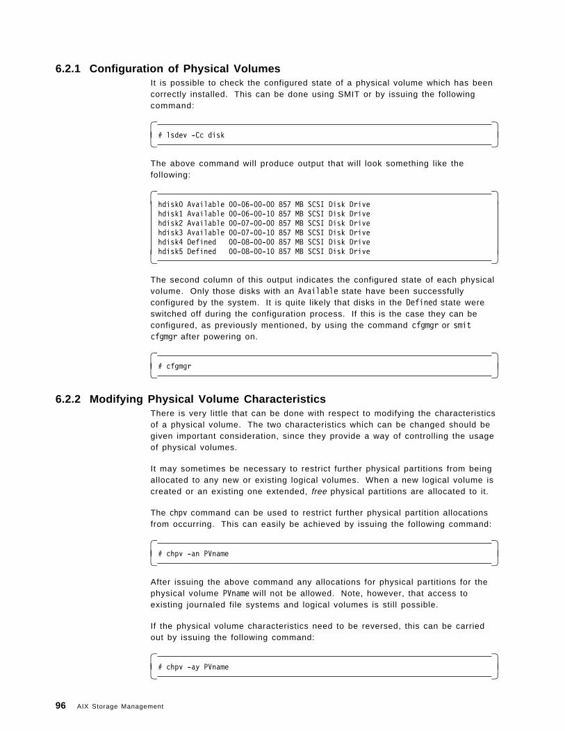
6.2.1 Configuration of Physical VolumesIt is possible to check the configured state of a physical volume which has beencorrectly installed. This can be done using SMIT or by issuing the followingcommand:
� �# lsdev -Cc disk� �
The above command will produce output that will look something like thefollowing:
� �hdisk0 Available 00-06-00-00 857 MB SCSI Disk Drivehdisk1 Available 00-06-00-10 857 MB SCSI Disk Drivehdisk2 Available 00-07-00-00 857 MB SCSI Disk Drivehdisk3 Available 00-07-00-10 857 MB SCSI Disk Drivehdisk4 Defined 00-08-00-00 857 MB SCSI Disk Drivehdisk5 Defined 00-08-00-10 857 MB SCSI Disk Drive� �
The second column of this output indicates the configured state of each physicalvolume. Only those disks with an Available state have been successfullyconfigured by the system. It is quite likely that disks in the Defined state wereswitched off during the configuration process. If this is the case they can beconfigured, as previously mentioned, by using the command cfgmgr or smitcfgmgr after powering on.
� �# cfgmgr� �
6.2.2 Modifying Physical Volume CharacteristicsThere is very little that can be done with respect to modifying the characteristicsof a physical volume. The two characteristics which can be changed should begiven important consideration, since they provide a way of controlling the usageof physical volumes.
It may sometimes be necessary to restrict further physical partitions from beingallocated to any new or existing logical volumes. When a new logical volume iscreated or an existing one extended, free physical partitions are allocated to it.
The chpv command can be used to restrict further physical partition allocationsfrom occurring. This can easily be achieved by issuing the following command:
� �# chpv -an PVname� �
After issuing the above command any allocations for physical partitions for thephysical volume PVname will not be allowed. Note, however, that access toexisting journaled file systems and logical volumes is still possible.
If the physical volume characteristics need to be reversed, this can be carriedout by issuing the following command:
� �# chpv -ay PVname� �
96 AIX Storage Management
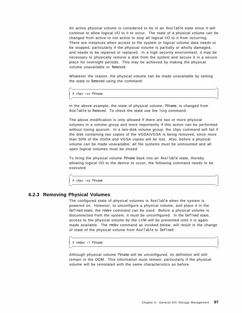
An active physical volume is considered to be in an Available state since it willcontinue to allow logical I/O to it to occur. The state of a physical volume can bechanged from active to not active to stop all logical I/O to it from occurring.There are instances when access to file system or logical volume data needs tobe stopped, particularly if the physical volume is partially or wholly damaged,and needs to be repaired or replaced. In a high security environment, it may benecessary to physically remove a disk from the system and secure it in a secureplace for overnight periods. This may be achieved by making the physicalvolume unavailable or Removed.
Whatever the reason, the physical volume can be made unavailable by settingthe state to Removed using the command:
� �# chpv -vr PVname� �
In the above example, the state of physical volume, PVname, is changed fromAvailable to Removed. To check the state use the lsvg command.
The above modification is only allowed if there are two or more physicalvolumes in a volume group and more importantly if this action can be performedwithout losing quorum. In a two-disk volume group, the chpv command will fail ifthe disk containing two copies of the VGDA/VGSA is being removed, since morethan 50% of the VGDA and VGSA copies will be lost. Also, before a physicalvolume can be made unavailable, all file systems must be unmounted and allopen logical volumes must be closed.
To bring the physical volume PVname back into an Available state, therebyallowing logical I/O to the device to occur, the following command needs to beexecuted:
� �# chpv -va PVname� �
6.2.3 Removing Physical VolumesThe configured state of physical volumes is Available when the system ispowered on. However, to unconfigure a physical volume, and place it in theDefined state, the rmdev command can be used. Before a physical volume isdisconnected from the system, it must be unconfigured. In the Defined state,access to the physical volume by the LVM will be prevented until it is againmade available. The rmdev command as invoked below, will result in the changeof state of the physical volume from Available to Defined:
� �# rmdev -l PVname� �
Although physical volume PVname will be unconfigured, its definition will stillremain in the ODM. This information must remain, particularly if the physicalvolume will be reinstated with the same characteristics as before.
Chapter 6. General AIX Storage Management 97
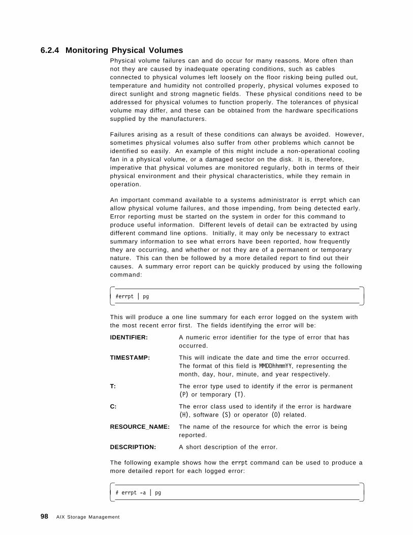
6.2.4 Monitoring Physical VolumesPhysical volume failures can and do occur for many reasons. More often thannot they are caused by inadequate operating conditions, such as cablesconnected to physical volumes left loosely on the floor risking being pulled out,temperature and humidity not controlled properly, physical volumes exposed todirect sunlight and strong magnetic fields. These physical conditions need to beaddressed for physical volumes to function properly. The tolerances of physicalvolume may differ, and these can be obtained from the hardware specificationssupplied by the manufacturers.
Failures arising as a result of these conditions can always be avoided. However,sometimes physical volumes also suffer from other problems which cannot beidentified so easily. An example of this might include a non-operational coolingfan in a physical volume, or a damaged sector on the disk. It is, therefore,imperative that physical volumes are monitored regularly, both in terms of theirphysical environment and their physical characteristics, while they remain inoperation.
An important command available to a systems administrator is errpt which canallow physical volume failures, and those impending, from being detected early.Error reporting must be started on the system in order for this command toproduce useful information. Different levels of detail can be extracted by usingdifferent command line options. Initially, it may only be necessary to extractsummary information to see what errors have been reported, how frequentlythey are occurring, and whether or not they are of a permanent or temporarynature. This can then be followed by a more detailed report to find out theircauses. A summary error report can be quickly produced by using the followingcommand:
� �#errpt | pg� �
This will produce a one line summary for each error logged on the system withthe most recent error first. The fields identifying the error will be:
IDENTIFIER: A numeric error identifier for the type of error that hasoccurred.
TIMESTAMP: This will indicate the date and time the error occurred.The format of this field is MMDDhhmmYY, representing themonth, day, hour, minute, and year respectively.
T: The error type used to identify if the error is permanent(P) or temporary (T).
C: The error class used to identify if the error is hardware(H), software (S) or operator (O) related.
RESOURCE_NAME: The name of the resource for which the error is beingreported.
DESCRIPTION: A short description of the error.
The following example shows how the errpt command can be used to produce amore detailed report for each logged error:
� �# errpt -a | pg� �
98 AIX Storage Management
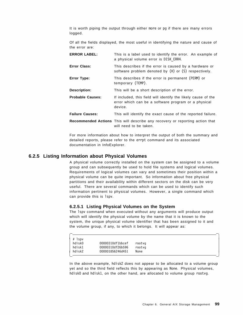
It is worth piping the output through either more or pg if there are many errorslogged.
Of all the fields displayed, the most useful in identifying the nature and cause ofthe error are:
ERROR LABEL: This is a label used to identify the error. An example ofa physical volume error is DISK_ERR4.
Error Class: This describes if the error is caused by a hardware orsoftware problem denoted by (H) or (S) respectively.
Error Type: This describes if the error is permanent (PERM) ortemporary (TEMP).
Description: This will be a short description of the error.
Probable Causes: If included, this field will identify the likely cause of theerror which can be a software program or a physicaldevice.
Failure Causes: This will identify the exact cause of the reported failure.
Recommended Actions This will describe any recovery or reporting action thatwill need to be taken.
For more information about how to interpret the output of both the summary anddetailed reports, please refer to the errpt command and its associateddocumentation in InfoExplorer.
6.2.5 Listing Information about Physical VolumesA physical volume correctly installed on the system can be assigned to a volumegroup and can subsequently be used to hold file systems and logical volumes.Requirements of logical volumes can vary and sometimes their position within aphysical volume can be quite important. So information about free physicalpartitions and their availability within different sectors on the disk can be veryuseful. There are several commands which can be used to identify suchinformation pertinent to physical volumes. However, a single command whichcan provide this is lspv.
6.2.5.1 Listing Physical Volumes on the SystemThe lspv command when executed without any arguments will produce outputwhich will identify the physical volume by the name that it is known to thesystem, the unique physical volume identifier that has been assigned to it andthe volume group, if any, to which it belongs. It will appear as:
� �# lspvhdisk0 00000310df1bbcef rootvghdisk1 00000310df26b596 rootvghdisk2 000001856246d451 None� �
In the above example, hdisk2 does not appear to be allocated to a volume groupyet and so the third field reflects this by appearing as None. Physical volumes,hdisk0 and hdisk1, on the other hand, are allocated to volume group rootvg.
Chapter 6. General AIX Storage Management 99

6.2.5.2 Listing Physical Volume CharacteristicsThe lspv command can also be used to retrieve more detailed information aboutphysical volumes. The command must however be invoked with the name of thedisk for which information is required as the argument.
For example:
� �# lspv hdisk0� �
If the physical volume being interrogated is currently not allocated to a volumegroup, no detailed information can be produced about it and an appropriatemessage will be output to indicate this.
You will note that the information on the left shows detail pertinent to thephysical volume itself, whereas that on the right provides detail about thevolume group that the physical volume is allocated to. Some of the detailextracted from this output will be discussed in more detail in sections 6.3,“Managing Volume Groups” on page 103 and 6.4, “Managing Logical Volumes”on page 113, since it is more relevant there.
In brief, the information produced is:
PHYSICAL VOLUME: The name of the physical volume.
PV IDENTIFIER: Physical volume identifier unique to the system.
PV STATE: Availability state of the physical volume for logicalI/O. This state can be changed using the chpvcommand mentioned in section 6.2.2, “ModifyingPhysical Volume Characteristics” on page 96.
STALE PARTITIONS: The number of physical partitions that are markedstale. Partitions can become stale when the physicalvolume is temporarily made unavailable while theirmirrored copies on other physical volumes change.This will be reviewed in sections 6.3, “ManagingVolume Groups” on page 103 and 6.4, “ManagingLogical Volumes” on page 113.
PP SIZE: The size of the physical partition, set when thevolume group is added. This will be reviewed insections 6.3, “Managing Volume Groups” onpage 103 and 6.4, “Managing Logical Volumes” onpage 113.
TOTAL PPs: The total number of physical partitions that exist onthe physical volume.
FREE PPs: The number of physical partitions available on thephysical volume that have not been allocated to filesystems or logical volumes.
USED PPs: The number of physical partitions on the physicalvolume that have already been allocated to filesystems or logical volumes.
FREE DISTRIBUTION: This lists the number of physical partitions that areavailable in each of the various regions of thephysical volume. The use of this information will be
100 AIX Storage Management
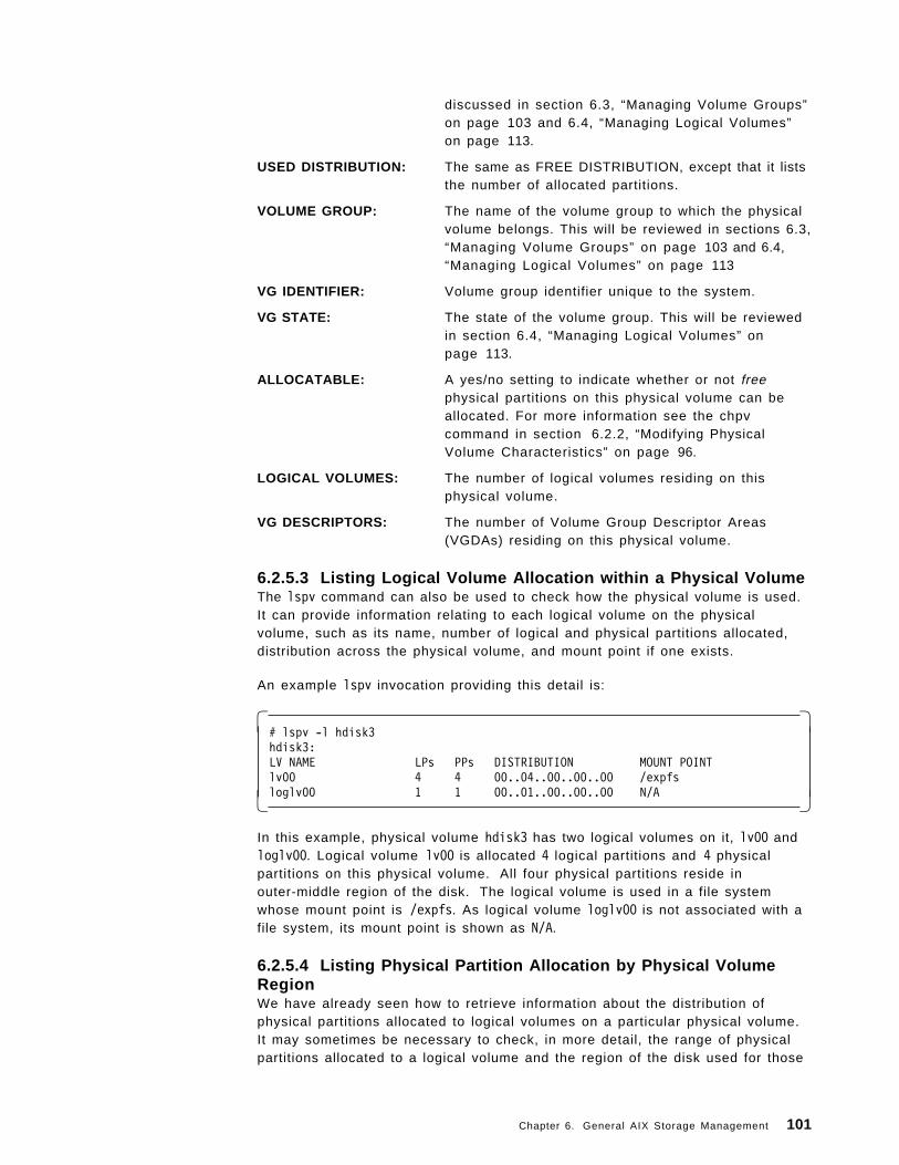
discussed in section 6.3, “Managing Volume Groups”on page 103 and 6.4, “Managing Logical Volumes”on page 113.
USED DISTRIBUTION: The same as FREE DISTRIBUTION, except that it liststhe number of allocated partitions.
VOLUME GROUP: The name of the volume group to which the physicalvolume belongs. This will be reviewed in sections 6.3,“Managing Volume Groups” on page 103 and 6.4,“Managing Logical Volumes” on page 113
VG IDENTIFIER: Volume group identifier unique to the system.
VG STATE: The state of the volume group. This will be reviewedin section 6.4, “Managing Logical Volumes” onpage 113.
ALLOCATABLE: A yes/no setting to indicate whether or not freephysical partitions on this physical volume can beallocated. For more information see the chpvcommand in section 6.2.2, “Modifying PhysicalVolume Characteristics” on page 96.
LOGICAL VOLUMES: The number of logical volumes residing on thisphysical volume.
VG DESCRIPTORS: The number of Volume Group Descriptor Areas(VGDAs) residing on this physical volume.
6.2.5.3 Listing Logical Volume Allocation within a Physical VolumeThe lspv command can also be used to check how the physical volume is used.It can provide information relating to each logical volume on the physicalvolume, such as its name, number of logical and physical partitions allocated,distribution across the physical volume, and mount point if one exists.
An example lspv invocation providing this detail is:
� �# lspv -l hdisk3hdisk3:LV NAME LPs PPs DISTRIBUTION MOUNT POINTlv00 4 4 00..04..00..00..00 /expfsloglv00 1 1 00..01..00..00..00 N/A� �
In this example, physical volume hdisk3 has two logical volumes on it, lv00 andloglv00. Logical volume lv00 is allocated 4 logical partitions and 4 physicalpartitions on this physical volume. All four physical partitions reside inouter-middle region of the disk. The logical volume is used in a file systemwhose mount point is /expfs. As logical volume loglv00 is not associated with afile system, its mount point is shown as N/A.
6.2.5.4 Listing Physical Partition Allocation by Physical VolumeRegionWe have already seen how to retrieve information about the distribution ofphysical partitions allocated to logical volumes on a particular physical volume.It may sometimes be necessary to check, in more detail, the range of physicalpartitions allocated to a logical volume and the region of the disk used for those
Chapter 6. General AIX Storage Management 101
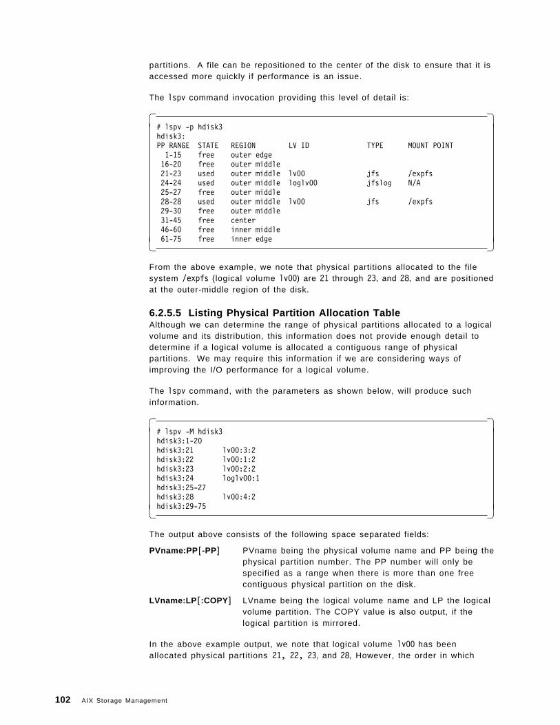
partitions. A file can be repositioned to the center of the disk to ensure that it isaccessed more quickly if performance is an issue.
The lspv command invocation providing this level of detail is:
� �# lspv -p hdisk3hdisk3:PP RANGE STATE REGION LV ID TYPE MOUNT POINT1-15 free outer edge16-20 free outer middle21-23 used outer middle lv00 jfs /expfs24-24 used outer middle loglv00 jfslog N/A25-27 free outer middle28-28 used outer middle lv00 jfs /expfs29-30 free outer middle31-45 free center46-60 free inner middle61-75 free inner edge� �
From the above example, we note that physical partitions allocated to the filesystem /expfs (logical volume lv00) are 21 through 23, and 28, and are positionedat the outer-middle region of the disk.
6.2.5.5 Listing Physical Partition Allocation TableAlthough we can determine the range of physical partitions allocated to a logicalvolume and its distribution, this information does not provide enough detail todetermine if a logical volume is allocated a contiguous range of physicalpartitions. We may require this information if we are considering ways ofimproving the I/O performance for a logical volume.
The lspv command, with the parameters as shown below, will produce suchinformation.
� �# lspv -M hdisk3hdisk3:1-20hdisk3:21 lv00:3:2hdisk3:22 lv00:1:2hdisk3:23 lv00:2:2hdisk3:24 loglv00:1hdisk3:25-27hdisk3:28 lv00:4:2hdisk3:29-75� �
The output above consists of the following space separated fields:
PVname:PP [-PP] PVname being the physical volume name and PP being thephysical partition number. The PP number will only bespecified as a range when there is more than one freecontiguous physical partition on the disk.
LVname:LP [:COPY ] LVname being the logical volume name and LP the logicalvolume partition. The COPY value is also output, if thelogical partition is mirrored.
In the above example output, we note that logical volume lv00 has beenallocated physical partitions 21, 22, 23, and 28, However, the order in which
102 AIX Storage Management
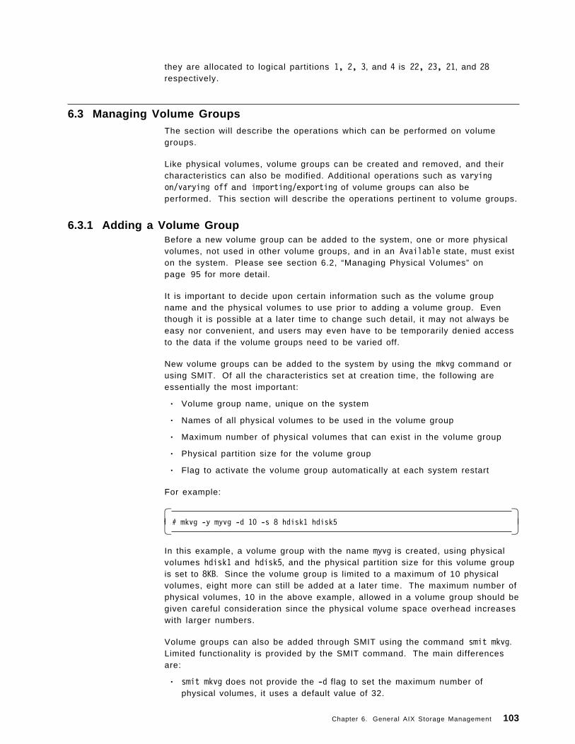
they are allocated to logical partitions 1, 2, 3, and 4 is 22, 23, 21, and 28respectively.
6.3 Managing Volume GroupsThe section will describe the operations which can be performed on volumegroups.
Like physical volumes, volume groups can be created and removed, and theircharacteristics can also be modified. Additional operations such as varyingon/varying off and importing/exporting of volume groups can also beperformed. This section will describe the operations pertinent to volume groups.
6.3.1 Adding a Volume GroupBefore a new volume group can be added to the system, one or more physicalvolumes, not used in other volume groups, and in an Available state, must existon the system. Please see section 6.2, “Managing Physical Volumes” onpage 95 for more detail.
It is important to decide upon certain information such as the volume groupname and the physical volumes to use prior to adding a volume group. Eventhough it is possible at a later time to change such detail, it may not always beeasy nor convenient, and users may even have to be temporarily denied accessto the data if the volume groups need to be varied off.
New volume groups can be added to the system by using the mkvg command orusing SMIT. Of all the characteristics set at creation time, the following areessentially the most important:
• Volume group name, unique on the system
• Names of all physical volumes to be used in the volume group
• Maximum number of physical volumes that can exist in the volume group
• Physical partition size for the volume group
• Flag to activate the volume group automatically at each system restart
For example:
� �# mkvg -y myvg -d 10 -s 8 hdisk1 hdisk5� �
In this example, a volume group with the name myvg is created, using physicalvolumes hdisk1 and hdisk5, and the physical partition size for this volume groupis set to 8KB. Since the volume group is limited to a maximum of 10 physicalvolumes, eight more can still be added at a later time. The maximum number ofphysical volumes, 10 in the above example, allowed in a volume group should begiven careful consideration since the physical volume space overhead increaseswith larger numbers.
Volume groups can also be added through SMIT using the command smit mkvg.Limited functionality is provided by the SMIT command. The main differencesare:
• smit mkvg does not provide the -d flag to set the maximum number ofphysical volumes, it uses a default value of 32.
Chapter 6. General AIX Storage Management 103
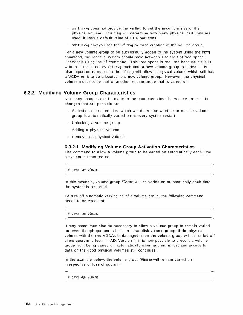
• smit mkvg does not provide the -m flag to set the maximum size of thephysical volume. This flag will determine how many physical partitions areused, it uses a default value of 1016 partitions.
• smit mkvg always uses the -f flag to force creation of the volume group.
For a new volume group to be successfully added to the system using the mkvgcommand, the root file system should have between 1 to 2MB of free space.Check this using the df command. This free space is required because a file iswritten in the directory /etc/vg each time a new volume group is added. It isalso important to note that the -f flag will allow a physical volume which still hasa VGDA on it to be allocated to a new volume group. However, the physicalvolume must not be part of another volume group that is varied on.
6.3.2 Modifying Volume Group CharacteristicsNot many changes can be made to the characteristics of a volume group. Thechanges that are possible are:
• Activation characteristics, which will determine whether or not the volumegroup is automatically varied on at every system restart
• Unlocking a volume group
• Adding a physical volume
• Removing a physical volume
6.3.2.1 Modifying Volume Group Activation CharacteristicsThe command to allow a volume group to be varied on automatically each timea system is restarted is:
� �# chvg -ay VGname� �
In this example, volume group VGname will be varied on automatically each timethe system is restarted.
To turn off automatic varying on of a volume group, the following commandneeds to be executed:
� �# chvg -an VGname� �
It may sometimes also be necessary to allow a volume group to remain variedon, even though quorum is lost. In a two-disk volume group, if the physicalvolume with the two VGDAs is damaged, then the volume group will be varied offsince quorum is lost. In AIX Version 4, it is now possible to prevent a volumegroup from being varied off automatically when quorum is lost and access todata on the good physical volumes still continues.
In the example below, the volume group VGname will remain varied onirrespective of loss of quorum.
� �# chvg -Qn VGname� �
104 AIX Storage Management
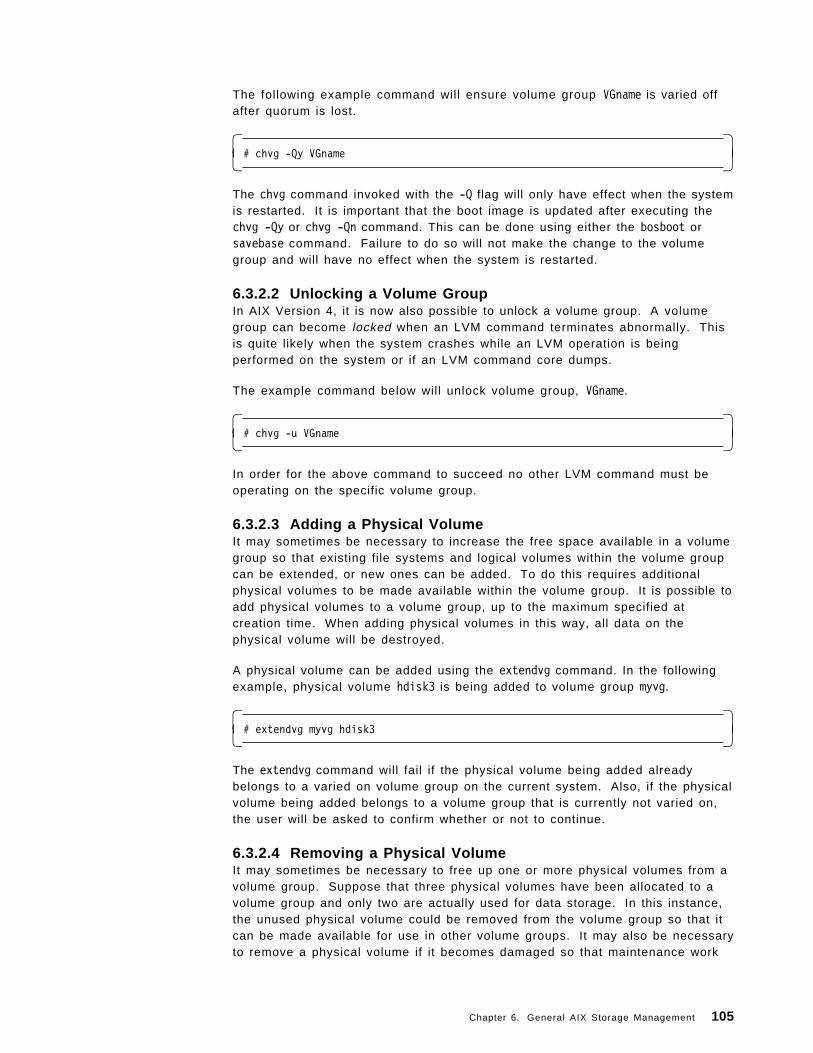
The following example command will ensure volume group VGname is varied offafter quorum is lost.
� �# chvg -Qy VGname� �
The chvg command invoked with the -Q flag will only have effect when the systemis restarted. It is important that the boot image is updated after executing thechvg -Qy or chvg -Qn command. This can be done using either the bosboot orsavebase command. Failure to do so will not make the change to the volumegroup and will have no effect when the system is restarted.
6.3.2.2 Unlocking a Volume GroupIn AIX Version 4, it is now also possible to unlock a volume group. A volumegroup can become locked when an LVM command terminates abnormally. Thisis quite likely when the system crashes while an LVM operation is beingperformed on the system or if an LVM command core dumps.
The example command below will unlock volume group, VGname.
� �# chvg -u VGname� �
In order for the above command to succeed no other LVM command must beoperating on the specific volume group.
6.3.2.3 Adding a Physical VolumeIt may sometimes be necessary to increase the free space available in a volumegroup so that existing file systems and logical volumes within the volume groupcan be extended, or new ones can be added. To do this requires additionalphysical volumes to be made available within the volume group. It is possible toadd physical volumes to a volume group, up to the maximum specified atcreation time. When adding physical volumes in this way, all data on thephysical volume will be destroyed.
A physical volume can be added using the extendvg command. In the followingexample, physical volume hdisk3 is being added to volume group myvg.
� �# extendvg myvg hdisk3� �
The extendvg command will fail if the physical volume being added alreadybelongs to a varied on volume group on the current system. Also, if the physicalvolume being added belongs to a volume group that is currently not varied on,the user will be asked to confirm whether or not to continue.
6.3.2.4 Removing a Physical VolumeIt may sometimes be necessary to free up one or more physical volumes from avolume group. Suppose that three physical volumes have been allocated to avolume group and only two are actually used for data storage. In this instance,the unused physical volume could be removed from the volume group so that itcan be made available for use in other volume groups. It may also be necessaryto remove a physical volume if it becomes damaged so that maintenance work
Chapter 6. General AIX Storage Management 105
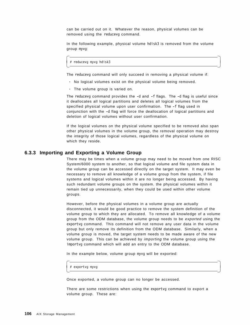
can be carried out on it. Whatever the reason, physical volumes can beremoved using the reducevg command.
In the following example, physical volume hdisk3 is removed from the volumegroup myvg:
� �# reducevg myvg hdisk3� �
The reducevg command will only succeed in removing a physical volume if:
• No logical volumes exist on the physical volume being removed.
• The volume group is varied on.
The reducevg command provides the -d and -f flags. The -d flag is useful sinceit deallocates all logical partitions and deletes all logical volumes from thespecified physical volume upon user confirmation. The -f flag used inconjunction with the -d flag will force the deallocation of logical partitions anddeletion of logical volumes without user confirmation.
If the logical volumes on the physical volume specified to be removed also spanother physical volumes in the volume group, the removal operation may destroythe integrity of those logical volumes, regardless of the physical volume onwhich they reside.
6.3.3 Importing and Exporting a Volume GroupThere may be times when a volume group may need to be moved from one RISCSystem/6000 system to another, so that logical volume and file system data inthe volume group can be accessed directly on the target system. It may even benecessary to remove all knowledge of a volume group from the system, if filesystems and logical volumes within it are no longer being accessed. By havingsuch redundant volume groups on the system. the physical volumes within itremain tied up unnecessarily, when they could be used within other volumegroups.
However, before the physical volumes in a volume group are actuallydisconnected, it would be good practice to remove the system definition of thevolume group to which they are allocated. To remove all knowledge of a volumegroup from the ODM database, the volume group needs to be exported using theexportvg command. This command will not remove any user data in the volumegroup but only remove its definition from the ODM database. Similarly, when avolume group is moved, the target system needs to be made aware of the newvolume group. This can be achieved by importing the volume group using theimportvg command which will add an entry to the ODM database.
In the example below, volume group myvg will be exported:
� �# exportvg myvg� �
Once exported, a volume group can no longer be accessed.
There are some restrictions when using the exportvg command to export avolume group. These are:
106 AIX Storage Management
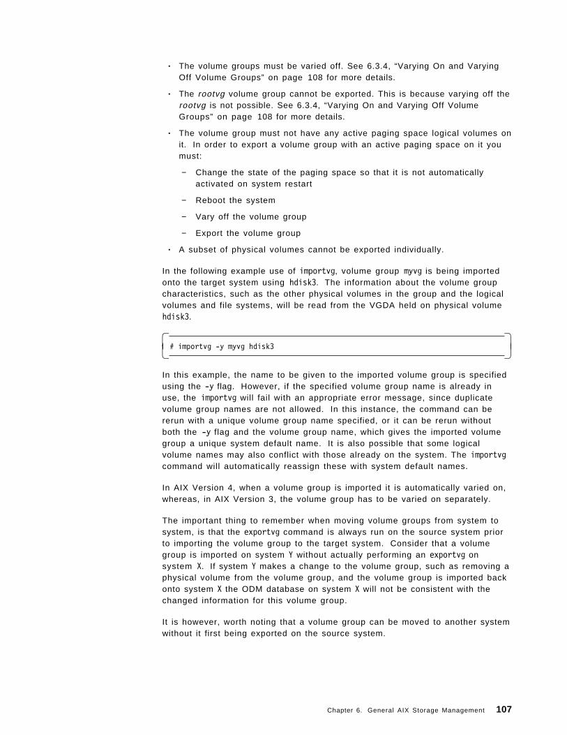
• The volume groups must be varied off. See 6.3.4, “Varying On and VaryingOff Volume Groups” on page 108 for more details.
• The rootvg volume group cannot be exported. This is because varying off therootvg is not possible. See 6.3.4, “Varying On and Varying Off VolumeGroups” on page 108 for more details.
• The volume group must not have any active paging space logical volumes onit. In order to export a volume group with an active paging space on it youmust:
− Change the state of the paging space so that it is not automaticallyactivated on system restart
− Reboot the system
− Vary off the volume group
− Export the volume group
• A subset of physical volumes cannot be exported individually.
In the following example use of importvg, volume group myvg is being importedonto the target system using hdisk3. The information about the volume groupcharacteristics, such as the other physical volumes in the group and the logicalvolumes and file systems, will be read from the VGDA held on physical volumehdisk3.
� �# importvg -y myvg hdisk3� �
In this example, the name to be given to the imported volume group is specifiedusing the -y flag. However, if the specified volume group name is already inuse, the importvg will fail with an appropriate error message, since duplicatevolume group names are not allowed. In this instance, the command can bererun with a unique volume group name specified, or it can be rerun withoutboth the -y flag and the volume group name, which gives the imported volumegroup a unique system default name. It is also possible that some logicalvolume names may also conflict with those already on the system. The importvgcommand will automatically reassign these with system default names.
In AIX Version 4, when a volume group is imported it is automatically varied on,whereas, in AIX Version 3, the volume group has to be varied on separately.
The important thing to remember when moving volume groups from system tosystem, is that the exportvg command is always run on the source system priorto importing the volume group to the target system. Consider that a volumegroup is imported on system Y without actually performing an exportvg onsystem X. If system Y makes a change to the volume group, such as removing aphysical volume from the volume group, and the volume group is imported backonto system X the ODM database on system X will not be consistent with thechanged information for this volume group.
It is however, worth noting that a volume group can be moved to another systemwithout it first being exported on the source system.
Chapter 6. General AIX Storage Management 107
6.3.4 Varying On and Varying Off Volume GroupsBefore administrative activities such as opening of logical volumes and mountingof file systems can be performed, the relevant volume groups need to be madeavailable. This can be achieved by varying on a volume group using thevaryonvg command. Likewise, when access to a volume group needs to bestopped entirely, it can be varied off after unmounting all file systems andclosing all open logical volumes within it. The varyoffvg command can be usedto vary off a volume group.
During the varying on process, a number of different operations are performed inorder to make a volume group available. They are:
• The VGDA and VGSA information is read from each of the physical volumesin the volume group.
• Each physical volume′s VGDA and VGSA header and trailer timestamps arevalidated. If, for example, the VGDA header and trailer timestamps on aparticular physical volume do not match, it is likely that the organizationalinformation held within it will be inconsistent.
• If the number of valid VGDAs found represents a majority, that is more than50%, the volume group will be varied on. If not, the varying on process willfail. The vary on process can be made to continue even when quorum is lostby using this -f flag to varyonvg.
• Since, the valid VGDA with the latest timestamp is likely to hold the mostrecent information about the organization of the volume group, it is used tooverwrite all other VGDAs in the volume group.
• If any invalid VGSAs (where the timestamps do not match) are found, thensyncvg is run to resynchronize any stale partitions within the volume group.
The following example shows how varyonvg can be used to varyon a volumegroup.
� �#varyonvg myvg� �
This command will vary on volume group myvg based on the varying on processmentioned above. If quorum was lost, the volume group myvg would not bevaried on. With a number of optional flags specified with the varyonvg command,the default processing can be overridden.
The optional flags are:
-f Forces the volume group to be varied on even though amajority of VGDAs does not exist. Forcing a volume groupto vary on could be quite dangerous, particularly if adamaged physical volume is holding logical partitions of alogical volume which is being updated. This would causecorruption of the data.
-n Disables the synchronization of the stale physicalpartitions within the volume group. This allows flexibility tothe systems administrator in providing control over howthe volume group can be recovered.
-p This permits a volume group to be varied on only when allthe physical volumes in the volume group are available.
108 AIX Storage Management
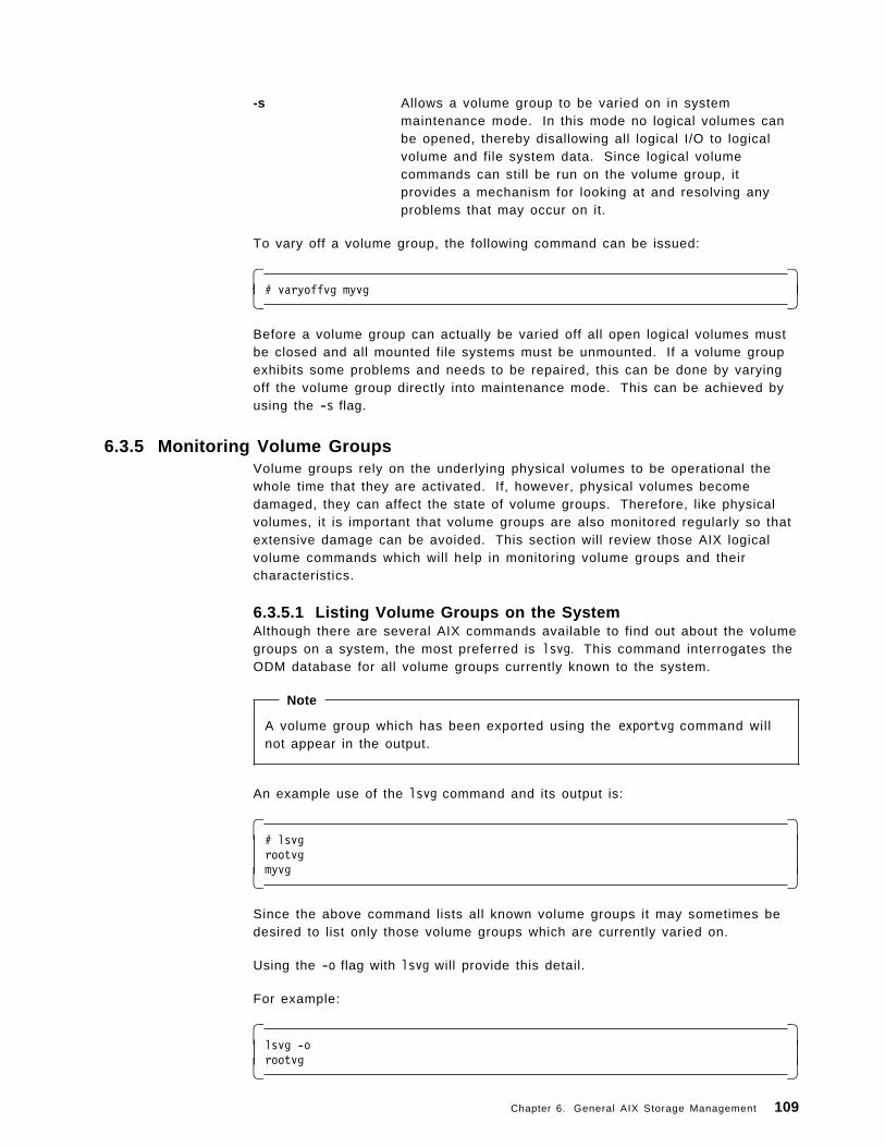
-s Allows a volume group to be varied on in systemmaintenance mode. In this mode no logical volumes canbe opened, thereby disallowing all logical I/O to logicalvolume and file system data. Since logical volumecommands can still be run on the volume group, itprovides a mechanism for looking at and resolving anyproblems that may occur on it.
To vary off a volume group, the following command can be issued:
� �# varyoffvg myvg� �
Before a volume group can actually be varied off all open logical volumes mustbe closed and all mounted file systems must be unmounted. If a volume groupexhibits some problems and needs to be repaired, this can be done by varyingoff the volume group directly into maintenance mode. This can be achieved byusing the -s flag.
6.3.5 Monitoring Volume GroupsVolume groups rely on the underlying physical volumes to be operational thewhole time that they are activated. If, however, physical volumes becomedamaged, they can affect the state of volume groups. Therefore, like physicalvolumes, it is important that volume groups are also monitored regularly so thatextensive damage can be avoided. This section will review those AIX logicalvolume commands which will help in monitoring volume groups and theircharacteristics.
6.3.5.1 Listing Volume Groups on the SystemAlthough there are several AIX commands available to find out about the volumegroups on a system, the most preferred is lsvg. This command interrogates theODM database for all volume groups currently known to the system.
Note
A volume group which has been exported using the exportvg command willnot appear in the output.
An example use of the lsvg command and its output is:
� �# lsvgrootvgmyvg� �
Since the above command lists all known volume groups it may sometimes bedesired to list only those volume groups which are currently varied on.
Using the -o flag with lsvg will provide this detail.
For example:
� �lsvg -orootvg� �
Chapter 6. General AIX Storage Management 109
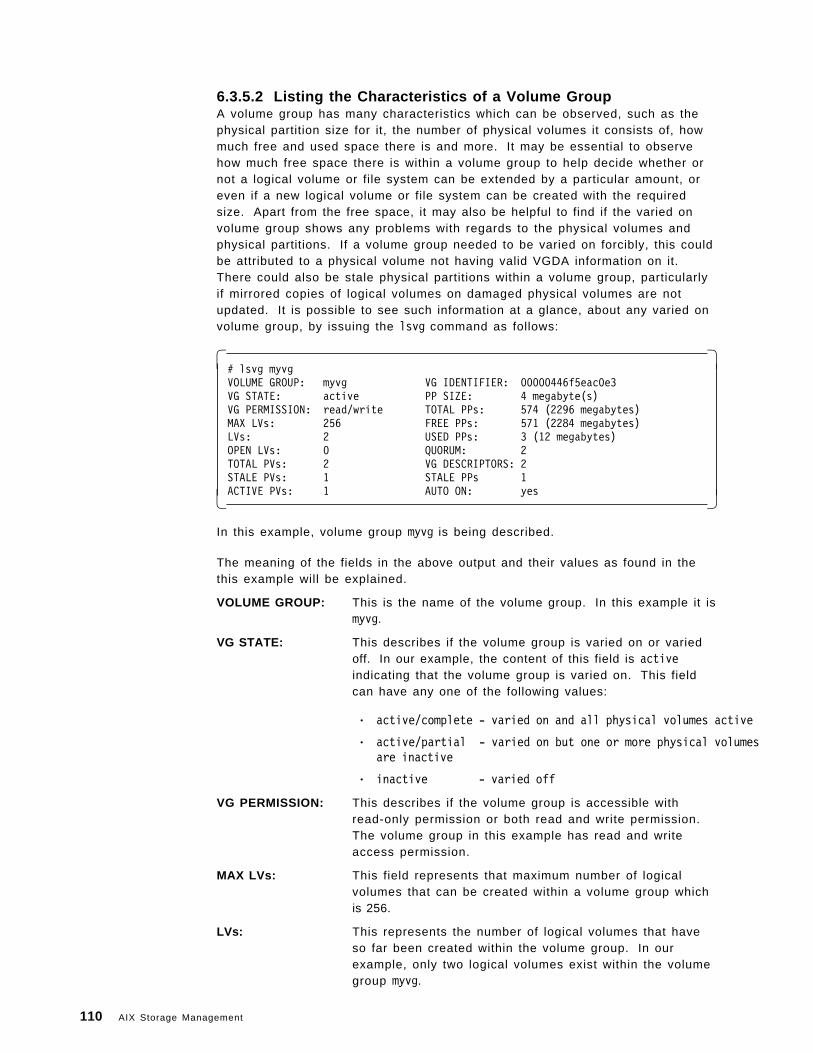
6.3.5.2 Listing the Characteristics of a Volume GroupA volume group has many characteristics which can be observed, such as thephysical partition size for it, the number of physical volumes it consists of, howmuch free and used space there is and more. It may be essential to observehow much free space there is within a volume group to help decide whether ornot a logical volume or file system can be extended by a particular amount, oreven if a new logical volume or file system can be created with the requiredsize. Apart from the free space, it may also be helpful to find if the varied onvolume group shows any problems with regards to the physical volumes andphysical partitions. If a volume group needed to be varied on forcibly, this couldbe attributed to a physical volume not having valid VGDA information on it.There could also be stale physical partitions within a volume group, particularlyif mirrored copies of logical volumes on damaged physical volumes are notupdated. It is possible to see such information at a glance, about any varied onvolume group, by issuing the lsvg command as follows:
� �# lsvg myvgVOLUME GROUP: myvg VG IDENTIFIER: 00000446f5eac0e3VG STATE: active PP SIZE: 4 megabyte(s)VG PERMISSION: read/write TOTAL PPs: 574 (2296 megabytes)MAX LVs: 256 FREE PPs: 571 (2284 megabytes)LVs: 2 USED PPs: 3 (12 megabytes)OPEN LVs: 0 QUORUM: 2TOTAL PVs: 2 VG DESCRIPTORS: 2STALE PVs: 1 STALE PPs 1ACTIVE PVs: 1 AUTO ON: yes� �
In this example, volume group myvg is being described.
The meaning of the fields in the above output and their values as found in thethis example will be explained.
VOLUME GROUP: This is the name of the volume group. In this example it ismyvg.
VG STATE: This describes if the volume group is varied on or variedoff. In our example, the content of this field is activeindicating that the volume group is varied on. This fieldcan have any one of the following values:
• active/complete - varied on and all physical volumes active
• active/partial - varied on but one or more physical volumesare inactive
• inactive - varied off
VG PERMISSION: This describes if the volume group is accessible withread-only permission or both read and write permission.The volume group in this example has read and writeaccess permission.
MAX LVs: This field represents that maximum number of logicalvolumes that can be created within a volume group whichis 256.
LVs: This represents the number of logical volumes that haveso far been created within the volume group. In ourexample, only two logical volumes exist within the volumegroup myvg.
110 AIX Storage Management
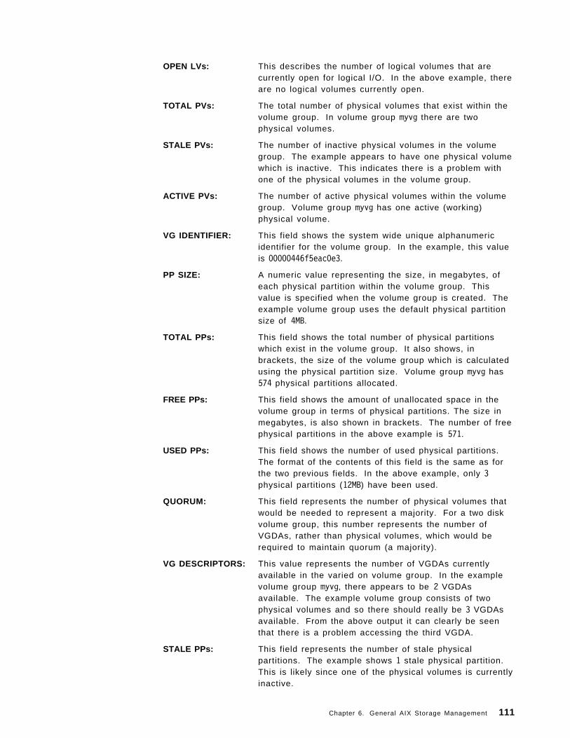
OPEN LVs: This describes the number of logical volumes that arecurrently open for logical I/O. In the above example, thereare no logical volumes currently open.
TOTAL PVs: The total number of physical volumes that exist within thevolume group. In volume group myvg there are twophysical volumes.
STALE PVs: The number of inactive physical volumes in the volumegroup. The example appears to have one physical volumewhich is inactive. This indicates there is a problem withone of the physical volumes in the volume group.
ACTIVE PVs: The number of active physical volumes within the volumegroup. Volume group myvg has one active (working)physical volume.
VG IDENTIFIER: This field shows the system wide unique alphanumericidentifier for the volume group. In the example, this valueis 00000446f5eac0e3.
PP SIZE: A numeric value representing the size, in megabytes, ofeach physical partition within the volume group. Thisvalue is specified when the volume group is created. Theexample volume group uses the default physical partitionsize of 4MB.
TOTAL PPs: This field shows the total number of physical partitionswhich exist in the volume group. It also shows, inbrackets, the size of the volume group which is calculatedusing the physical partition size. Volume group myvg has574 physical partitions allocated.
FREE PPs: This field shows the amount of unallocated space in thevolume group in terms of physical partitions. The size inmegabytes, is also shown in brackets. The number of freephysical partitions in the above example is 571.
USED PPs: This field shows the number of used physical partitions.The format of the contents of this field is the same as forthe two previous fields. In the above example, only 3physical partitions (12MB) have been used.
QUORUM: This field represents the number of physical volumes thatwould be needed to represent a majority. For a two diskvolume group, this number represents the number ofVGDAs, rather than physical volumes, which would berequired to maintain quorum (a majority).
VG DESCRIPTORS: This value represents the number of VGDAs currentlyavailable in the varied on volume group. In the examplevolume group myvg, there appears to be 2 VGDAsavailable. The example volume group consists of twophysical volumes and so there should really be 3 VGDAsavailable. From the above output it can clearly be seenthat there is a problem accessing the third VGDA.
STALE PPs: This field represents the number of stale physicalpartitions. The example shows 1 stale physical partition.This is likely since one of the physical volumes is currentlyinactive.
Chapter 6. General AIX Storage Management 111
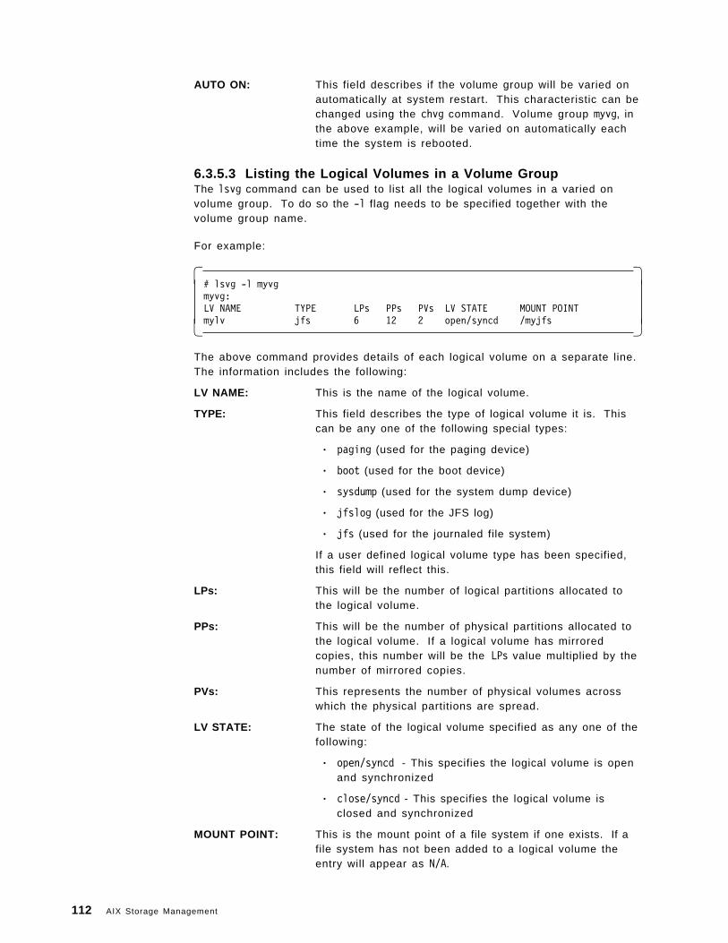
AUTO ON: This field describes if the volume group will be varied onautomatically at system restart. This characteristic can bechanged using the chvg command. Volume group myvg, inthe above example, will be varied on automatically eachtime the system is rebooted.
6.3.5.3 Listing the Logical Volumes in a Volume GroupThe lsvg command can be used to list all the logical volumes in a varied onvolume group. To do so the -l flag needs to be specified together with thevolume group name.
For example:
� �# lsvg -l myvgmyvg:LV NAME TYPE LPs PPs PVs LV STATE MOUNT POINTmylv jfs 6 12 2 open/syncd /myjfs� �
The above command provides details of each logical volume on a separate line.The information includes the following:
LV NAME: This is the name of the logical volume.
TYPE: This field describes the type of logical volume it is. Thiscan be any one of the following special types:
• paging (used for the paging device)
• boot (used for the boot device)
• sysdump (used for the system dump device)
• jfslog (used for the JFS log)
• jfs (used for the journaled file system)
If a user defined logical volume type has been specified,this field will reflect this.
LPs: This will be the number of logical partitions allocated tothe logical volume.
PPs: This will be the number of physical partitions allocated tothe logical volume. If a logical volume has mirroredcopies, this number will be the LPs value multiplied by thenumber of mirrored copies.
PVs: This represents the number of physical volumes acrosswhich the physical partitions are spread.
LV STATE: The state of the logical volume specified as any one of thefollowing:
• open/syncd - This specifies the logical volume is openand synchronized
• close/syncd - This specifies the logical volume isclosed and synchronized
MOUNT POINT: This is the mount point of a file system if one exists. If afile system has not been added to a logical volume theentry will appear as N/A.
112 AIX Storage Management
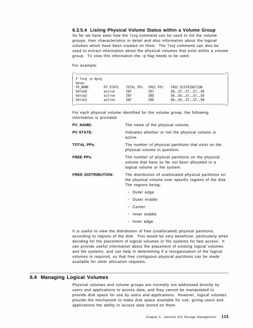
6.3.5.4 Listing Physical Volume Status within a Volume GroupSo far we have seen how the lsvg command can be used to list the volumegroups, their characteristics in detail and also information about the logicalvolumes which have been created on them. The lsvg command can also beused to extract information about the physical volumes that exist within a volumegroup. To view this information the -p flag needs to be used.
For example:
� �# lsvg -p myvgmyvg:PV_NAME PV STATE TOTAL PPs FREE PPs FREE DISTRIBUTIONhdisk0 active 287 267 58..37..57..57..58hdisk2 active 287 280 58..50..57..57..58hdisk3 active 287 280 58..50..57..57..58� �
For each physical volume identified for the volume group, the followinginformation is provided:
PV_NAME: The name of the physical volume.
PV STATE: Indicates whether or not the physical volume isactive.
TOTAL PPs: The number of physical partitions that exist on thephysical volume in question.
FREE PPs: The number of physical partitions on the physicalvolume that have so far not been allocated to alogical volume or file system.
FREE DISTRIBUTION: The distribution of unallocated physical partitions onthe physical volume over specific regions of the disk.The regions being:
• Outer edge
• Outer middle
• Center
• Inner middle
• Inner edge
It is useful to view the distribution of free (unallocated) physical partitions,according to regions of the disk. This would be very beneficial, particularly whendeciding for the placement of logical volumes or file systems for fast access. Itcan provide useful information about the placement of existing logical volumesand file systems, and can help in determining if a reorganization of the logicalvolumes is required, so that free contiguous physical partitions can be madeavailable for other allocation requests.
6.4 Managing Logical VolumesPhysical volumes and volume groups are normally not addressed directly byusers and applications to access data, and they cannot be manipulated toprovide disk space for use by users and applications. However, logical volumesprovide the mechanism to make disk space available for use, giving users andapplications the ability to access data stored on them.
Chapter 6. General AIX Storage Management 113
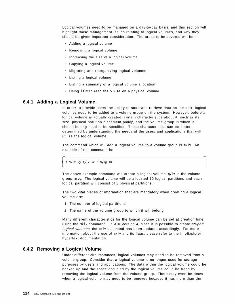
Logical volumes need to be managed on a day-to-day basis, and this section willhighlight those management issues relating to logical volumes, and why theyshould be given important consideration. The areas to be covered will be:
• Adding a logical volume
• Removing a logical volume
• Increasing the size of a logical volume
• Copying a logical volume
• Migrating and reorganizing logical volumes
• Listing a logical volume
• Listing a summary of a logical volume allocation
• Using lslv to read the VGDA on a physical volume
6.4.1 Adding a Logical VolumeIn order to provide users the ability to store and retrieve data on the disk, logicalvolumes need to be added to a volume group on the system. However, before alogical volume is actually created, certain characteristics about it, such as itssize, physical partition placement policy, and the volume group in which itshould belong need to be specified. These characteristics can be betterdetermined by understanding the needs of the users and applications that willutilize the logical volume.
The command which will add a logical volume to a volume group is mklv. Anexample of this command is:
� �# mklv -y mylv -c 2 myvg 10� �
The above example command will create a logical volume mylv in the volumegroup myvg. The logical volume will be allocated 10 logical partitions and eachlogical partition will consist of 2 physical partitions.
The two vital pieces of information that are mandatory when creating a logicalvolume are:
1. The number of logical partitions
2. The name of the volume group to which it wil l belong
Many different characteristics for the logical volume can be set at creation timeusing the mklv command. In AIX Version 4, since it is possible to create stripedlogical volumes, the mklv command has been updated accordingly. For moreinformation about the use of mklv and its flags, please refer to the InfoExplorerhypertext documentation.
6.4.2 Removing a Logical VolumeUnder different circumstances, logical volumes may need to be removed from avolume group. Consider that a logical volume is no longer used for storagepurposes by users and applications. The data within the logical volume could bebacked up and the space occupied by the logical volume could be freed byremoving the logical volume from the volume group. There may even be timeswhen a logical volume may need to be removed because it has more than the
114 AIX Storage Management
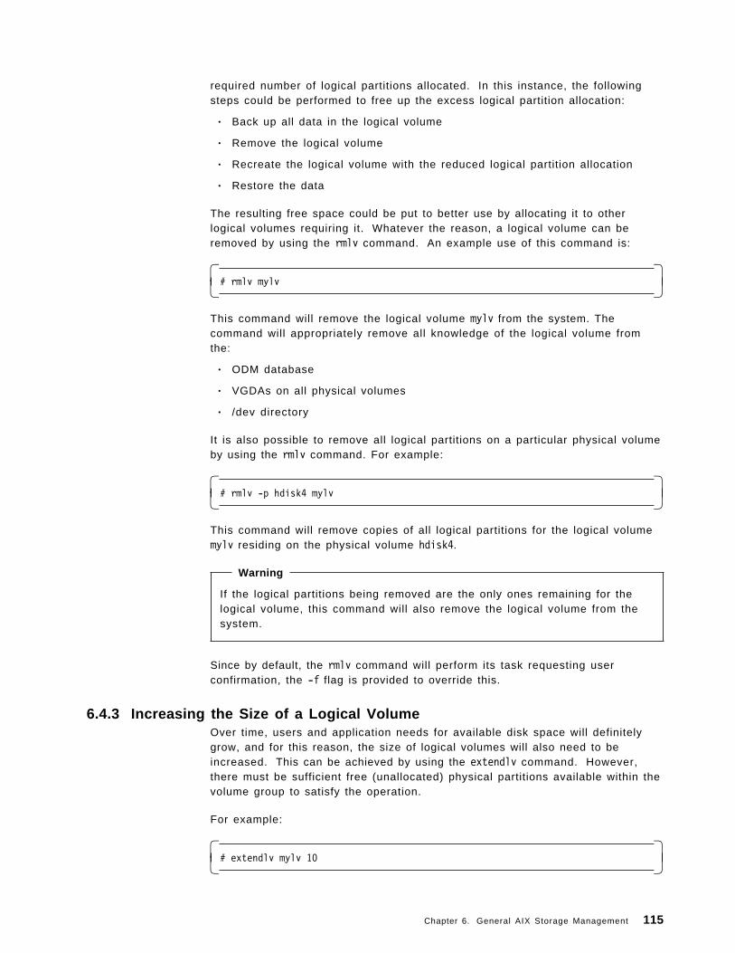
required number of logical partitions allocated. In this instance, the followingsteps could be performed to free up the excess logical partition allocation:
• Back up all data in the logical volume
• Remove the logical volume
• Recreate the logical volume with the reduced logical partition allocation
• Restore the data
The resulting free space could be put to better use by allocating it to otherlogical volumes requiring it. Whatever the reason, a logical volume can beremoved by using the rmlv command. An example use of this command is:
� �# rmlv mylv� �
This command will remove the logical volume mylv from the system. Thecommand will appropriately remove all knowledge of the logical volume fromthe:
• ODM database
• VGDAs on all physical volumes
• /dev directory
It is also possible to remove all logical partitions on a particular physical volumeby using the rmlv command. For example:
� �# rmlv -p hdisk4 mylv� �
This command will remove copies of all logical partitions for the logical volumemylv residing on the physical volume hdisk4.
Warning
If the logical partitions being removed are the only ones remaining for thelogical volume, this command will also remove the logical volume from thesystem.
Since by default, the rmlv command will perform its task requesting userconfirmation, the -f flag is provided to override this.
6.4.3 Increasing the Size of a Logical VolumeOver time, users and application needs for available disk space will definitelygrow, and for this reason, the size of logical volumes will also need to beincreased. This can be achieved by using the extendlv command. However,there must be sufficient free (unallocated) physical partitions available within thevolume group to satisfy the operation.
For example:
� �# extendlv mylv 10� �
Chapter 6. General AIX Storage Management 115
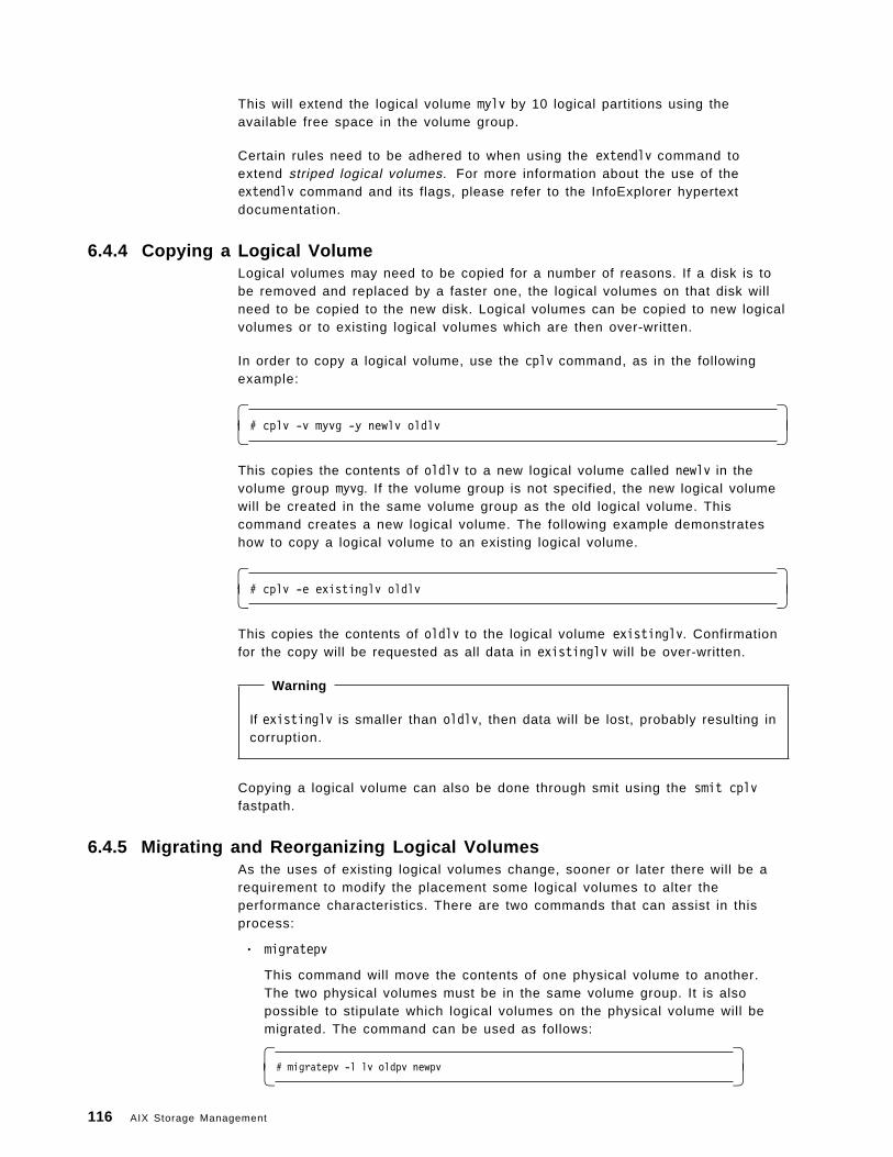
This will extend the logical volume mylv by 10 logical partitions using theavailable free space in the volume group.
Certain rules need to be adhered to when using the extendlv command toextend striped logical volumes. For more information about the use of theextendlv command and its flags, please refer to the InfoExplorer hypertextdocumentation.
6.4.4 Copying a Logical VolumeLogical volumes may need to be copied for a number of reasons. If a disk is tobe removed and replaced by a faster one, the logical volumes on that disk willneed to be copied to the new disk. Logical volumes can be copied to new logicalvolumes or to existing logical volumes which are then over-written.
In order to copy a logical volume, use the cplv command, as in the followingexample:
� �# cplv -v myvg -y newlv oldlv� �
This copies the contents of oldlv to a new logical volume called newlv in thevolume group myvg. If the volume group is not specified, the new logical volumewill be created in the same volume group as the old logical volume. Thiscommand creates a new logical volume. The following example demonstrateshow to copy a logical volume to an existing logical volume.
� �# cplv -e existinglv oldlv� �
This copies the contents of oldlv to the logical volume existinglv. Confirmationfor the copy will be requested as all data in existinglv will be over-written.
Warning
If existinglv is smaller than oldlv, then data will be lost, probably resulting incorruption.
Copying a logical volume can also be done through smit using the smit cplvfastpath.
6.4.5 Migrating and Reorganizing Logical VolumesAs the uses of existing logical volumes change, sooner or later there will be arequirement to modify the placement some logical volumes to alter theperformance characteristics. There are two commands that can assist in thisprocess:
• migratepv
This command will move the contents of one physical volume to another.The two physical volumes must be in the same volume group. It is alsopossible to stipulate which logical volumes on the physical volume will bemigrated. The command can be used as follows:
� �# migratepv -l lv oldpv newpv� �
116 AIX Storage Management
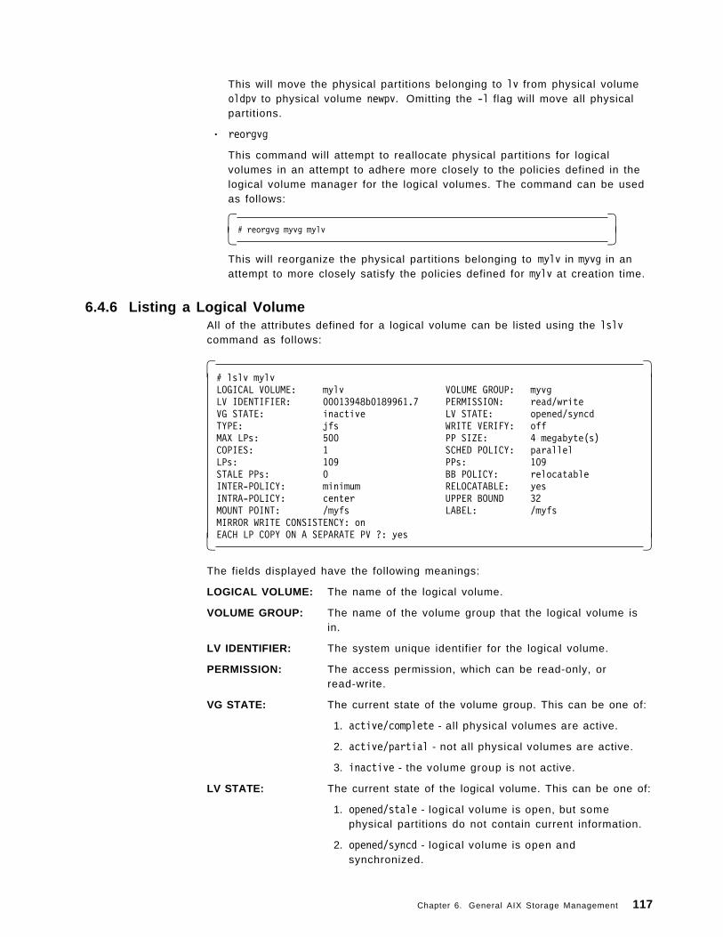
This will move the physical partitions belonging to lv from physical volumeoldpv to physical volume newpv. Omitting the -l flag will move all physicalpartitions.
• reorgvg
This command will attempt to reallocate physical partitions for logicalvolumes in an attempt to adhere more closely to the policies defined in thelogical volume manager for the logical volumes. The command can be usedas follows:
� �# reorgvg myvg mylv� �
This will reorganize the physical partitions belonging to mylv in myvg in anattempt to more closely satisfy the policies defined for mylv at creation time.
6.4.6 Listing a Logical VolumeAll of the attributes defined for a logical volume can be listed using the lslvcommand as follows:
� �# lslv mylvLOGICAL VOLUME: mylv VOLUME GROUP: myvgLV IDENTIFIER: 00013948b0189961.7 PERMISSION: read/writeVG STATE: inactive LV STATE: opened/syncdTYPE: jfs WRITE VERIFY: offMAX LPs: 500 PP SIZE: 4 megabyte(s)COPIES: 1 SCHED POLICY: parallelLPs: 109 PPs: 109STALE PPs: 0 BB POLICY: relocatableINTER-POLICY: minimum RELOCATABLE: yesINTRA-POLICY: center UPPER BOUND 32MOUNT POINT: /myfs LABEL: /myfsMIRROR WRITE CONSISTENCY: onEACH LP COPY ON A SEPARATE PV ?: yes� �
The fields displayed have the following meanings:
LOGICAL VOLUME: The name of the logical volume.
VOLUME GROUP: The name of the volume group that the logical volume isin.
LV IDENTIFIER: The system unique identifier for the logical volume.
PERMISSION: The access permission, which can be read-only, orread-write.
VG STATE: The current state of the volume group. This can be one of:
1. active/complete - all physical volumes are active.
2. active/partial - not all physical volumes are active.
3. inactive - the volume group is not active.
LV STATE: The current state of the logical volume. This can be one of:
1. opened/stale - logical volume is open, but somephysical partitions do not contain current information.
2. opened/syncd - logical volume is open andsynchronized.
Chapter 6. General AIX Storage Management 117
3. closed - logical volume has not been opened.
TYPE: The type of the logical volume (JFS for example).
WRITE VERIFY: Whether write verify is being used or not.
MAX LPs: The maximum number of logical partitions that the logicalvolume can contain.
PP SIZE: The size of the physical partitions in the logical volume.
COPIES: The number of copies of the logical volume that exist.
SCHED POLICY: Whether writes are to be scheduled serially, or in parallelto disk.
LPs: The current number of logical partitions in the logicalvolume.
PPs: The current number of physical partitions in the logicalvolume.
STALE PPs: The number of physical partitions in the logical volumethat do not contain current information.
BB POLICY: Whether bad block allocation is to be used or not for thislogical volume.
INTER-POLICY: Whether the maximum or minimum range of disks shouldbe used for logical partition allocation for this logicalvolume.
RELOCATABLE: Whether partitions can be relocated if a reorganizationoccurs.
INTRA-POLICY: Specifies the preferred location for physical partitions onthe disk. This can be edge, middle, or center.
UPPER BOUND: This indicates the maximum number of physical volumeswithin the volume group that can be used for physicalpartition allocation.
MOUNT POINT: If this logical volume contains a file system, then thisindicates the mount point for that file system.
MIRROR WRITE CONSISTENCY:Whether writes are cached to help ensure consistencybetween mirrored copies.
EACH LP COPY ON A SEPARATE PV ?:Whether the allocation policy is strict meaning that logicalvolume copies will be placed on separate physicalvolumes if possible.
6.4.7 Listing a Summary of a Logical Volume AllocationIf a summary of the physical partition usage for a logical volume is required,rather than a complete listing of all attributes, the following command can beused:
118 AIX Storage Management
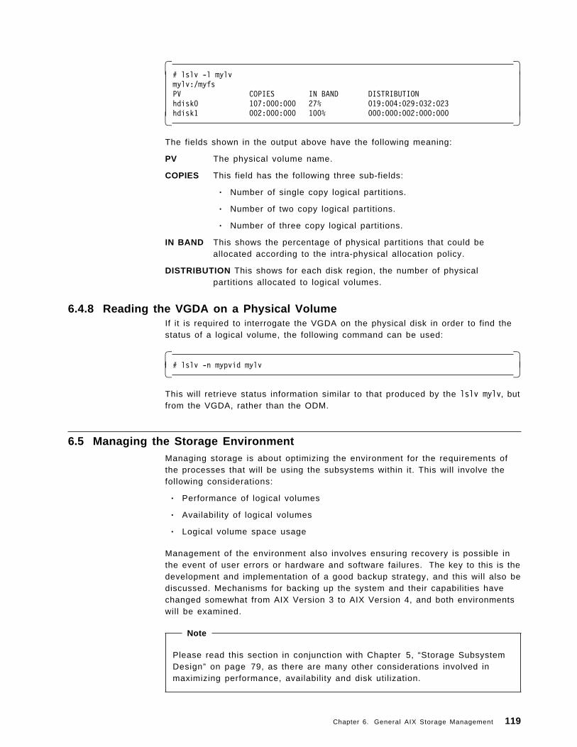
� �# lslv -l mylvmylv:/myfsPV COPIES IN BAND DISTRIBUTIONhdisk0 107:000:000 27% 019:004:029:032:023hdisk1 002:000:000 100% 000:000:002:000:000� �
The fields shown in the output above have the following meaning:
PV The physical volume name.
COPIES This field has the following three sub-fields:
• Number of single copy logical partitions.
• Number of two copy logical partitions.
• Number of three copy logical partitions.
IN BAND This shows the percentage of physical partitions that could beallocated according to the intra-physical allocation policy.
DISTRIBUTION This shows for each disk region, the number of physicalpartitions allocated to logical volumes.
6.4.8 Reading the VGDA on a Physical VolumeIf it is required to interrogate the VGDA on the physical disk in order to find thestatus of a logical volume, the following command can be used:
� �# lslv -n mypvid mylv� �
This will retrieve status information similar to that produced by the lslv mylv, butfrom the VGDA, rather than the ODM.
6.5 Managing the Storage EnvironmentManaging storage is about optimizing the environment for the requirements ofthe processes that will be using the subsystems within it. This will involve thefollowing considerations:
• Performance of logical volumes
• Availability of logical volumes
• Logical volume space usage
Management of the environment also involves ensuring recovery is possible inthe event of user errors or hardware and software failures. The key to this is thedevelopment and implementation of a good backup strategy, and this will also bediscussed. Mechanisms for backing up the system and their capabilities havechanged somewhat from AIX Version 3 to AIX Version 4, and both environmentswill be examined.
Note
Please read this section in conjunction with Chapter 5, “Storage SubsystemDesign” on page 79, as there are many other considerations involved inmaximizing performance, availability and disk utilization.
Chapter 6. General AIX Storage Management 119
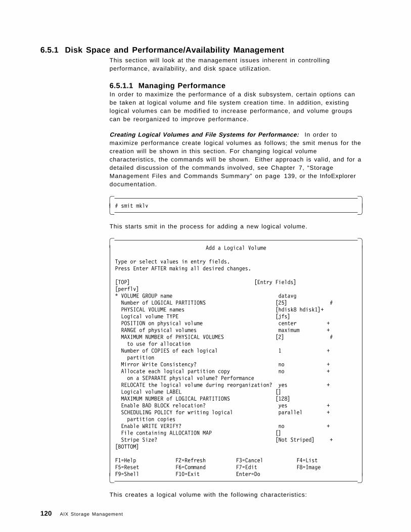
6.5.1 Disk Space and Performance/Availability ManagementThis section will look at the management issues inherent in controllingperformance, availability, and disk space utilization.
6.5.1.1 Managing PerformanceIn order to maximize the performance of a disk subsystem, certain options canbe taken at logical volume and file system creation time. In addition, existinglogical volumes can be modified to increase performance, and volume groupscan be reorganized to improve performance.
Creating Logical Volumes and File Systems for Performance: In order tomaximize performance create logical volumes as follows; the smit menus for thecreation will be shown in this section. For changing logical volumecharacteristics, the commands will be shown. Either approach is valid, and for adetailed discussion of the commands involved, see Chapter 7, “StorageManagement Files and Commands Summary” on page 139, or the InfoExplorerdocumentation.
� �# smit mklv� �
This starts smit in the process for adding a new logical volume.
� �Add a Logical Volume
Type or select values in entry fields.Press Enter AFTER making all desired changes.
[TOP] [Entry Fields][perflv]* VOLUME GROUP name datavgNumber of LOGICAL PARTITIONS [25] #PHYSICAL VOLUME names [hdisk8 hdisk1]+Logical volume TYPE [jfs]POSITION on physical volume center +RANGE of physical volumes maximum +MAXIMUM NUMBER of PHYSICAL VOLUMES [2] #to use for allocation
Number of COPIES of each logical 1 +partition
Mirror Write Consistency? no +Allocate each logical partition copy no +on a SEPARATE physical volume? Performance
RELOCATE the logical volume during reorganization? yes +Logical volume LABEL []MAXIMUM NUMBER of LOGICAL PARTITIONS [128]Enable BAD BLOCK relocation? yes +SCHEDULING POLICY for writing logical parallel +partition copies
Enable WRITE VERIFY? no +File containing ALLOCATION MAP []Stripe Size? [Not Striped] +
[BOTTOM]
F1=Help F2=Refresh F3=Cancel F4=ListF5=Reset F6=Command F7=Edit F8=ImageF9=Shell F10=Exit Enter=Do� �
This creates a logical volume with the following characteristics:
120 AIX Storage Management
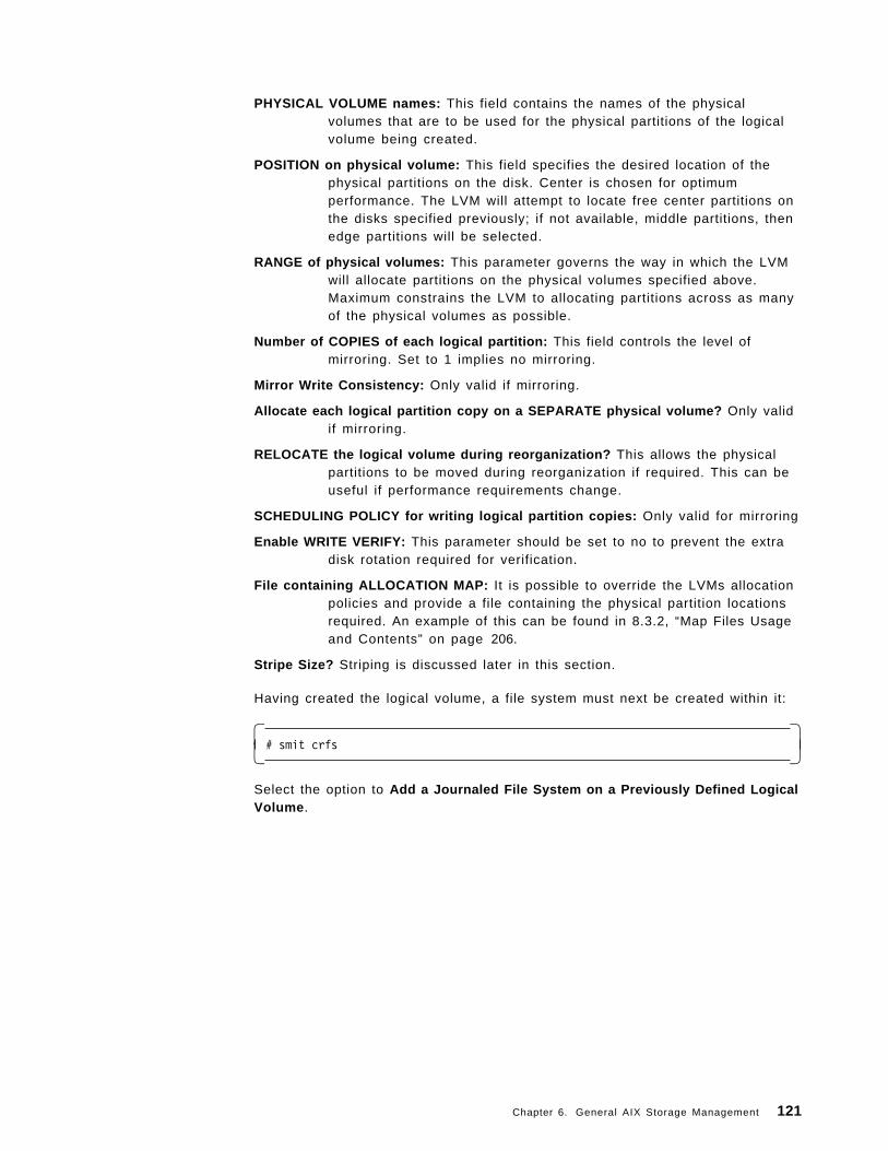
PHYSICAL VOLUME names: This field contains the names of the physicalvolumes that are to be used for the physical partitions of the logicalvolume being created.
POSITION on physical volume: This field specifies the desired location of thephysical partitions on the disk. Center is chosen for optimumperformance. The LVM will attempt to locate free center partitions onthe disks specified previously; if not available, middle partitions, thenedge partitions will be selected.
RANGE of physical volumes: This parameter governs the way in which the LVMwill allocate partitions on the physical volumes specified above.Maximum constrains the LVM to allocating partitions across as manyof the physical volumes as possible.
Number of COPIES of each logical partition: This field controls the level ofmirroring. Set to 1 implies no mirroring.
Mirror Write Consistency: Only valid if mirroring.
Allocate each logical partition copy on a SEPARATE physical volume? Only validif mirroring.
RELOCATE the logical volume during reorganization? This allows the physicalpartitions to be moved during reorganization if required. This can beuseful if performance requirements change.
SCHEDULING POLICY for writing logical partition copies: Only valid for mirroring
Enable WRITE VERIFY: This parameter should be set to no to prevent the extradisk rotation required for verification.
File containing ALLOCATION MAP: It is possible to override the LVMs allocationpolicies and provide a file containing the physical partition locationsrequired. An example of this can be found in 8.3.2, “Map Files Usageand Contents” on page 206.
Stripe Size? Striping is discussed later in this section.
Having created the logical volume, a file system must next be created within it:
� �# smit crfs� �
Select the option to Add a Journaled File System on a Previously Defined LogicalVolume .
Chapter 6. General AIX Storage Management 121
� �Add a Journaled File System on a Previously Defined Logical Volume
Type or select values in entry fields.Press Enter AFTER making all desired changes.
[Entry Field]* LOGICAL VOLUME name perflv +* MOUNT POINT [/tmp/nick]Mount AUTOMATICALLY at system restart? yes +PERMISSIONS read/write +Mount OPTIONS [] +Start Disk Accounting? no +Fragment Size (bytes) 4096 +Number of bytes per inode 4096 +Compression algorithm no +
F1=Help F2=Refresh F3=Cancel F4=ListF5=Reset F6=Command F7=Edit F8=ImageF9=Shell F10=Exit Enter=Do� �
This will create a file system with the following characteristics:
Fragment Size (bytes): This parameter controls the size of the basic unit ofallocation at the file system level. Setting this to 4096 createsfragments of the largest size possible, thereby minimizing theoverhead involved and maximizing performance.
Number of bytes per inode: This parameter governs the number of i-nodesactually created per number of bytes in the file system. This will haveno specific effect on performance.
Compression algorithm: To maximize performance, do not use compression.
Modifying Logical Volumes for Performance: In order to maximize theperformance of an existing logical volume do the following:
� �# chlv -a c LVname� �
This command will change the intra-disk physical allocation policy to use thecenter of the disk if possible. In order for existing partitions to take advantage ofthe new policy, the volume group will need reorganizing. This is discussed in thenext section. Partitions added if the logical volume is extended will be allocatedusing the new policy. LVname should be the name of the logical volume that is tobe changed.
� �# chlv -e x LVname� �
This command will change the inter-disk physical allocation policy to use themaximum number of disks possible within the volume group, for allocatingfurther physical partitions. Again, reorganization will be required if the existingpartitions that comprise the logical volume are to take advantage of this. LVnameshould be the name of the logical volume that is to be changed.
122 AIX Storage Management
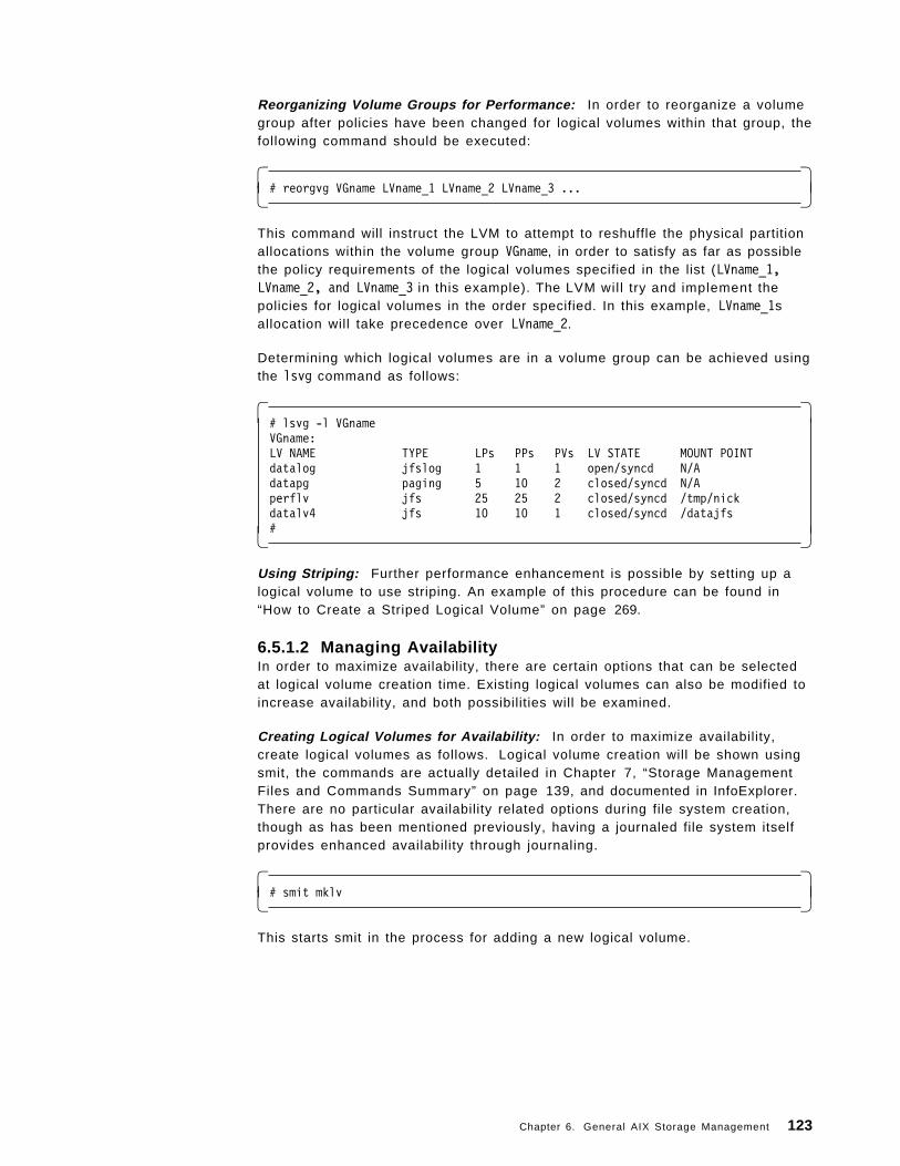
Reorganizing Volume Groups for Performance: In order to reorganize a volumegroup after policies have been changed for logical volumes within that group, thefollowing command should be executed:
� �# reorgvg VGname LVname_1 LVname_2 LVname_3 ...� �
This command will instruct the LVM to attempt to reshuffle the physical partitionallocations within the volume group VGname, in order to satisfy as far as possiblethe policy requirements of the logical volumes specified in the list (LVname_1,LVname_2, and LVname_3 in this example). The LVM wil l try and implement thepolicies for logical volumes in the order specified. In this example, LVname_1sallocation will take precedence over LVname_2.
Determining which logical volumes are in a volume group can be achieved usingthe lsvg command as follows:
� �# lsvg -l VGnameVGname:LV NAME TYPE LPs PPs PVs LV STATE MOUNT POINTdatalog jfslog 1 1 1 open/syncd N/Adatapg paging 5 10 2 closed/syncd N/Aperflv jfs 25 25 2 closed/syncd /tmp/nickdatalv4 jfs 10 10 1 closed/syncd /datajfs#� �
Using Striping: Further performance enhancement is possible by setting up alogical volume to use striping. An example of this procedure can be found in“How to Create a Striped Logical Volume” on page 269.
6.5.1.2 Managing AvailabilityIn order to maximize availability, there are certain options that can be selectedat logical volume creation time. Existing logical volumes can also be modified toincrease availability, and both possibilities will be examined.
Creating Logical Volumes for Availability: In order to maximize availability,create logical volumes as follows. Logical volume creation will be shown usingsmit, the commands are actually detailed in Chapter 7, “Storage ManagementFiles and Commands Summary” on page 139, and documented in InfoExplorer.There are no particular availability related options during file system creation,though as has been mentioned previously, having a journaled file system itselfprovides enhanced availability through journaling.
� �# smit mklv� �
This starts smit in the process for adding a new logical volume.
Chapter 6. General AIX Storage Management 123
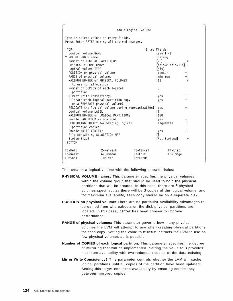
� �Add a Logical Volume
Type or select values in entry fields.Press Enter AFTER making all desired changes.
[TOP] [Entry Fields]Logical volume NAME [availlv]
* VOLUME GROUP name datavgNumber of LOGICAL PARTITIONS [25] #PHYSICAL VOLUME names [hdisk8 hdisk1 h]+Logical volume TYPE [jfs]POSITION on physical volume center +RANGE of physical volumes minimum +MAXIMUM NUMBER of PHYSICAL VOLUMES [1] #to use for allocation
Number of COPIES of each logical 3 +partition
Mirror Write Consistency? yes +Allocate each logical partition copy yes +on a SEPARATE physical volume?
RELOCATE the logical volume during reorganization? yes +Logical volume LABEL []MAXIMUM NUMBER of LOGICAL PARTITIONS [128]Enable BAD BLOCK relocation? yes +SCHEDULING POLICY for writing logical sequential +partition copies
Enable WRITE VERIFY? yes +File containing ALLOCATION MAP []Stripe Size? [Not Striped] +
[BOTTOM]
F1=Help F2=Refresh F3=Cancel F4=ListF5=Reset F6=Command F7=Edit F8=ImageF9=Shell F10=Exit Enter=Do� �
This creates a logical volume with the following characteristics:
PHYSICAL VOLUME names: This parameter specifies the physical volumeswithin the volume group that should be used to hold the physicalpartitions that will be created. In this case, there are 3 physicalvolumes specified, as there will be 3 copies of the logical volume, andfor maximum availability, each copy should be on a separate disk.
POSITION on physical volume: There are no particular availability advantages tobe gained from whereabouts on the disk physical partitions arelocated. In this case, center has been chosen to improveperformance.
RANGE of physical volumes: This parameter governs how many physicalvolumes the LVM will attempt to use when creating physical partitionsfor each copy. Setting the value to minimum instructs the LVM to use asfew physical volumes as is possible.
Number of COPIES of each logical partition: This parameter specifies the degreeof mirroring that will be implemented. Setting the value to 3 providesmaximum availability with two redundant copies of the data existing.
Mirror Write Consistency? This parameter controls whether the LVM will cachelogical partitions until all copies of the partition have been updated.Setting this to yes enhances availability by ensuring consistencybetween mirrored copies.
124 AIX Storage Management
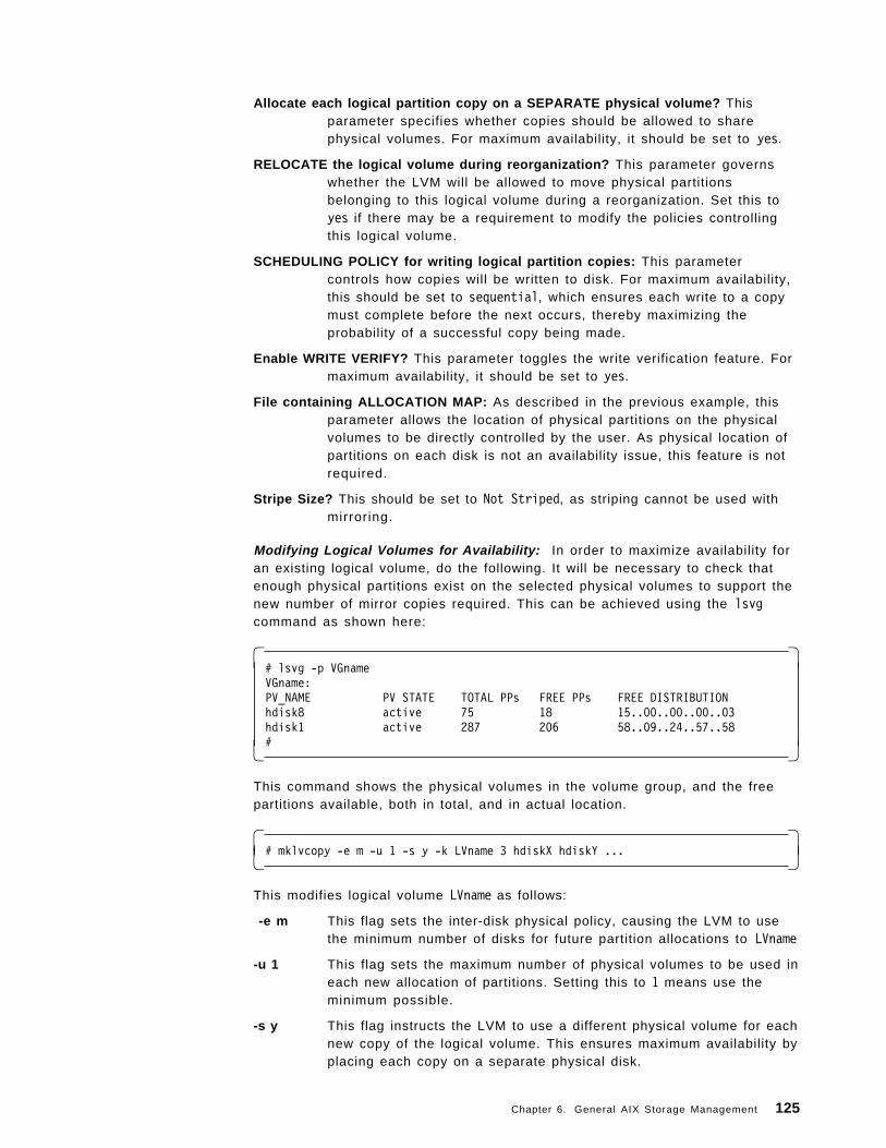
Allocate each logical partition copy on a SEPARATE physical volume? Thisparameter specifies whether copies should be allowed to sharephysical volumes. For maximum availability, it should be set to yes.
RELOCATE the logical volume during reorganization? This parameter governswhether the LVM will be allowed to move physical partitionsbelonging to this logical volume during a reorganization. Set this toyes if there may be a requirement to modify the policies controllingthis logical volume.
SCHEDULING POLICY for writing logical partition copies: This parametercontrols how copies will be written to disk. For maximum availability,this should be set to sequential, which ensures each write to a copymust complete before the next occurs, thereby maximizing theprobability of a successful copy being made.
Enable WRITE VERIFY? This parameter toggles the write verification feature. Formaximum availability, it should be set to yes.
File containing ALLOCATION MAP: As described in the previous example, thisparameter allows the location of physical partitions on the physicalvolumes to be directly controlled by the user. As physical location ofpartitions on each disk is not an availability issue, this feature is notrequired.
Stripe Size? This should be set to Not Striped, as striping cannot be used withmirroring.
Modifying Logical Volumes for Availability: In order to maximize availability foran existing logical volume, do the following. It will be necessary to check thatenough physical partitions exist on the selected physical volumes to support thenew number of mirror copies required. This can be achieved using the lsvgcommand as shown here:
� �# lsvg -p VGnameVGname:PV_NAME PV STATE TOTAL PPs FREE PPs FREE DISTRIBUTIONhdisk8 active 75 18 15..00..00..00..03hdisk1 active 287 206 58..09..24..57..58#� �
This command shows the physical volumes in the volume group, and the freepartitions available, both in total, and in actual location.
� �# mklvcopy -e m -u 1 -s y -k LVname 3 hdiskX hdiskY ...� �
This modifies logical volume LVname as follows:
-e m This flag sets the inter-disk physical policy, causing the LVM to usethe minimum number of disks for future partition allocations to LVname
-u 1 This flag sets the maximum number of physical volumes to be used ineach new allocation of partitions. Setting this to 1 means use theminimum possible.
-s y This flag instructs the LVM to use a different physical volume for eachnew copy of the logical volume. This ensures maximum availability byplacing each copy on a separate physical disk.
Chapter 6. General AIX Storage Management 125
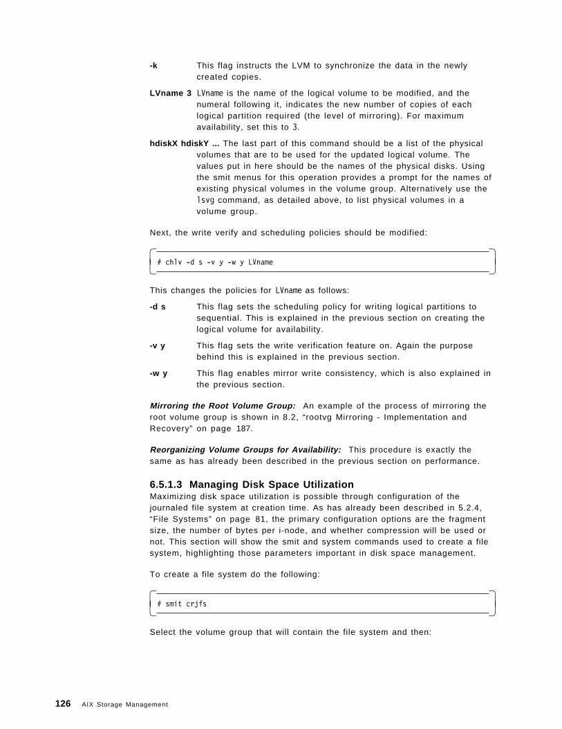
-k This flag instructs the LVM to synchronize the data in the newlycreated copies.
LVname 3 LVname is the name of the logical volume to be modified, and thenumeral following it, indicates the new number of copies of eachlogical partition required (the level of mirroring). For maximumavailability, set this to 3.
hdiskX hdiskY ... The last part of this command should be a list of the physicalvolumes that are to be used for the updated logical volume. Thevalues put in here should be the names of the physical disks. Usingthe smit menus for this operation provides a prompt for the names ofexisting physical volumes in the volume group. Alternatively use thelsvg command, as detailed above, to list physical volumes in avolume group.
Next, the write verify and scheduling policies should be modified:
� �# chlv -d s -v y -w y LVname� �
This changes the policies for LVname as follows:
-d s This flag sets the scheduling policy for writing logical partitions tosequential. This is explained in the previous section on creating thelogical volume for availability.
-v y This flag sets the write verification feature on. Again the purposebehind this is explained in the previous section.
-w y This flag enables mirror write consistency, which is also explained inthe previous section.
Mirroring the Root Volume Group: An example of the process of mirroring theroot volume group is shown in 8.2, “rootvg Mirroring - Implementation andRecovery” on page 187.
Reorganizing Volume Groups for Availability: This procedure is exactly thesame as has already been described in the previous section on performance.
6.5.1.3 Managing Disk Space UtilizationMaximizing disk space utilization is possible through configuration of thejournaled file system at creation time. As has already been described in 5.2.4,“File Systems” on page 81, the primary configuration options are the fragmentsize, the number of bytes per i-node, and whether compression will be used ornot. This section will show the smit and system commands used to create a filesystem, highlighting those parameters important in disk space management.
To create a file system do the following:
� �# smit crjfs� �
Select the volume group that will contain the file system and then:
126 AIX Storage Management
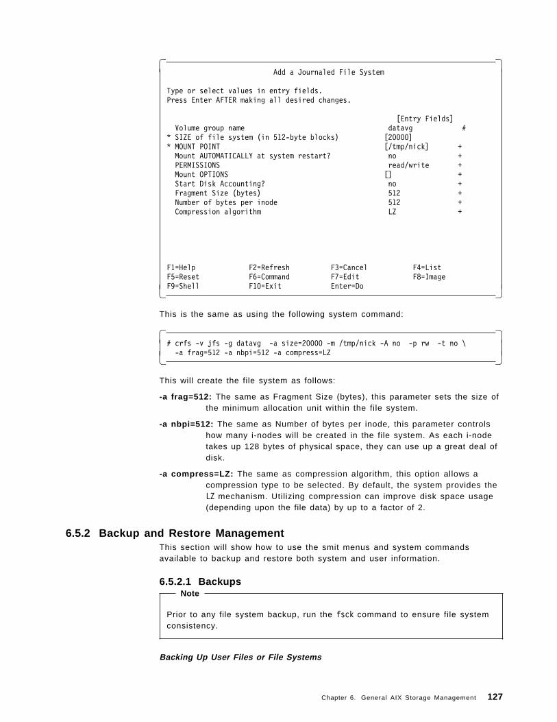
� �Add a Journaled File System
Type or select values in entry fields.Press Enter AFTER making all desired changes.
[Entry Fields]Volume group name datavg #
* SIZE of file system (in 512-byte blocks) [20000]* MOUNT POINT [/tmp/nick] +Mount AUTOMATICALLY at system restart? no +PERMISSIONS read/write +Mount OPTIONS [] +Start Disk Accounting? no +Fragment Size (bytes) 512 +Number of bytes per inode 512 +Compression algorithm LZ +
F1=Help F2=Refresh F3=Cancel F4=ListF5=Reset F6=Command F7=Edit F8=ImageF9=Shell F10=Exit Enter=Do� �
This is the same as using the following system command:
� �# crfs -v jfs -g datavg -a size=20000 -m /tmp/nick -A no -p rw -t no \-a frag=512 -a nbpi=512 -a compress=LZ� �
This will create the file system as follows:
-a frag=512: The same as Fragment Size (bytes), this parameter sets the size ofthe minimum allocation unit within the file system.
-a nbpi=512: The same as Number of bytes per inode, this parameter controlshow many i-nodes will be created in the file system. As each i-nodetakes up 128 bytes of physical space, they can use up a great deal ofdisk.
-a compress=LZ: The same as compression algorithm, this option allows acompression type to be selected. By default, the system provides theLZ mechanism. Utilizing compression can improve disk space usage(depending upon the file data) by up to a factor of 2.
6.5.2 Backup and Restore ManagementThis section will show how to use the smit menus and system commandsavailable to backup and restore both system and user information.
6.5.2.1 Backups Note
Prior to any file system backup, run the fsck command to ensure file systemconsistency.
Backing Up User Files or File Systems
Chapter 6. General AIX Storage Management 127
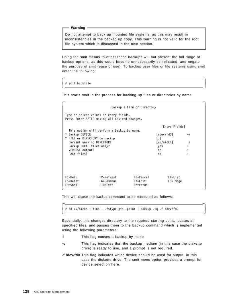
Warning
Do not attempt to back up mounted file systems, as this may result ininconsistencies in the backed up copy. This warning is not valid for the rootfile system which is discussed in the next section.
Using the smit menus to effect these backups will not present the full range ofbackup options, as this would become unnecessarily complicated, and negatethe purpose of smit (ease of use). To backup user files or file systems using smitenter the following:
� �# smit backfile� �
This starts smit in the process for backing up files or directories by name:
� �Backup a File or Directory
Type or select values in entry fields.Press Enter AFTER making all desired changes.
[Entry Fields]This option will perform a backup by name.
* Backup DEVICE [/dev/fd0] +/* FILE or DIRECTORY to backup [.]Current working DIRECTORY [/u/nickh] /Backup LOCAL files only? yes +VERBOSE output? no +PACK files? no +
F1=Help F2=Refresh F3=Cancel F4=ListF5=Reset F6=Command F7=Edit F8=ImageF9=Shell F10=Exit Enter=Do� �
This will cause the backup command to be executed as follows:
� �# cd /u/nickh ; find . -fstype jfs -print | backup -iq -f /dev/fd0� �
Essentially, this changes directory to the required starting point, locates allspecified files, and passes them to the backup command which is implementedusing the following parameters:
-i This flag causes a backup by name
-q This flag indicates that the backup medium (in this case the diskettedrive) is ready to use, and a prompt is not required.
-f /dev/fd0 This flag indicates which device should be used for output, in thiscase the diskette drive. The smit menu option provides a prompt fordevice selection here.
128 AIX Storage Management
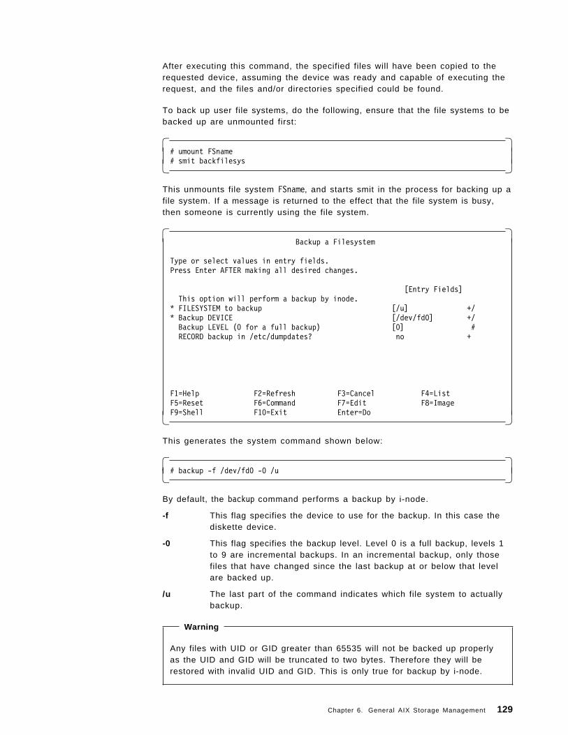
After executing this command, the specified files will have been copied to therequested device, assuming the device was ready and capable of executing therequest, and the files and/or directories specified could be found.
To back up user file systems, do the following, ensure that the file systems to bebacked up are unmounted first:
� �# umount FSname# smit backfilesys� �
This unmounts file system FSname, and starts smit in the process for backing up afile system. If a message is returned to the effect that the file system is busy,then someone is currently using the file system.
� �Backup a Filesystem
Type or select values in entry fields.Press Enter AFTER making all desired changes.
[Entry Fields]This option will perform a backup by inode.
* FILESYSTEM to backup [/u] +/* Backup DEVICE [/dev/fd0] +/Backup LEVEL (0 for a full backup) [0] #RECORD backup in /etc/dumpdates? no +
F1=Help F2=Refresh F3=Cancel F4=ListF5=Reset F6=Command F7=Edit F8=ImageF9=Shell F10=Exit Enter=Do� �
This generates the system command shown below:
� �# backup -f /dev/fd0 -0 /u� �
By default, the backup command performs a backup by i-node.
-f This flag specifies the device to use for the backup. In this case thediskette device.
-0 This flag specifies the backup level. Level 0 is a full backup, levels 1to 9 are incremental backups. In an incremental backup, only thosefiles that have changed since the last backup at or below that levelare backed up.
/u The last part of the command indicates which file system to actuallybackup.
Warning
Any files with UID or GID greater than 65535 will not be backed up properlyas the UID and GID will be truncated to two bytes. Therefore they will berestored with invalid UID and GID. This is only true for backup by i-node.
Chapter 6. General AIX Storage Management 129
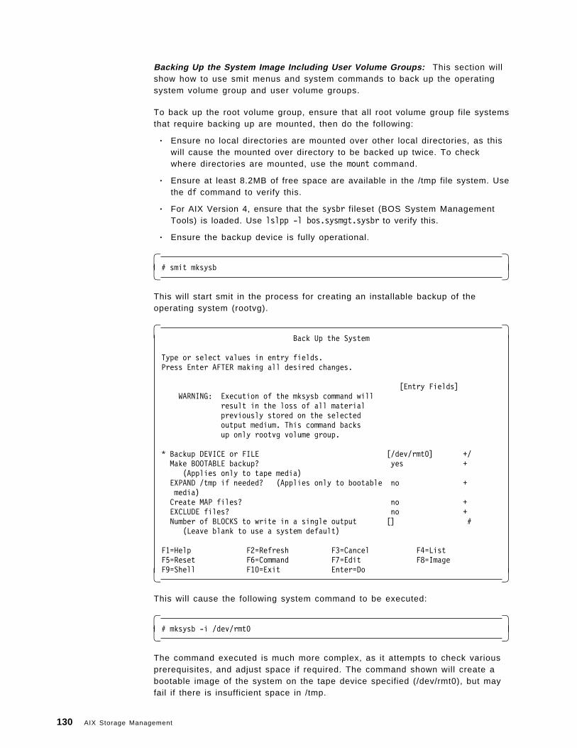
Backing Up the System Image Including User Volume Groups: This section willshow how to use smit menus and system commands to back up the operatingsystem volume group and user volume groups.
To back up the root volume group, ensure that all root volume group file systemsthat require backing up are mounted, then do the following:
• Ensure no local directories are mounted over other local directories, as thiswill cause the mounted over directory to be backed up twice. To checkwhere directories are mounted, use the mount command.
• Ensure at least 8.2MB of free space are available in the /tmp file system. Usethe df command to verify this.
• For AIX Version 4, ensure that the sysbr fileset (BOS System ManagementTools) is loaded. Use lslpp -l bos.sysmgt.sysbr to verify this.
• Ensure the backup device is fully operational.
� �# smit mksysb� �
This will start smit in the process for creating an installable backup of theoperating system (rootvg).
� �Back Up the System
Type or select values in entry fields.Press Enter AFTER making all desired changes.
[Entry Fields]WARNING: Execution of the mksysb command will
result in the loss of all materialpreviously stored on the selectedoutput medium. This command backsup only rootvg volume group.
* Backup DEVICE or FILE [/dev/rmt0] +/Make BOOTABLE backup? yes +
(Applies only to tape media)EXPAND /tmp if needed? (Applies only to bootable no +media)Create MAP files? no +EXCLUDE files? no +Number of BLOCKS to write in a single output [] #
(Leave blank to use a system default)
F1=Help F2=Refresh F3=Cancel F4=ListF5=Reset F6=Command F7=Edit F8=ImageF9=Shell F10=Exit Enter=Do� �
This will cause the following system command to be executed:
� �# mksysb -i /dev/rmt0� �
The command executed is much more complex, as it attempts to check variousprerequisites, and adjust space if required. The command shown will create abootable image of the system on the tape device specified (/dev/rmt0), but mayfail if there is insufficient space in /tmp.
130 AIX Storage Management
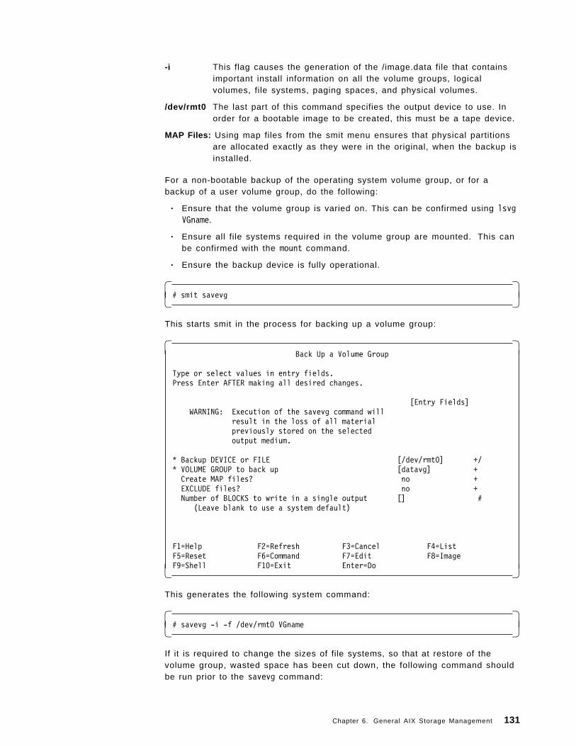
-i This flag causes the generation of the /image.data file that containsimportant install information on all the volume groups, logicalvolumes, file systems, paging spaces, and physical volumes.
/dev/rmt0 The last part of this command specifies the output device to use. Inorder for a bootable image to be created, this must be a tape device.
MAP Files: Using map files from the smit menu ensures that physical partitionsare allocated exactly as they were in the original, when the backup isinstalled.
For a non-bootable backup of the operating system volume group, or for abackup of a user volume group, do the following:
• Ensure that the volume group is varied on. This can be confirmed using lsvgVGname.
• Ensure all file systems required in the volume group are mounted. This canbe confirmed with the mount command.
• Ensure the backup device is fully operational.
� �# smit savevg� �
This starts smit in the process for backing up a volume group:
� �Back Up a Volume Group
Type or select values in entry fields.Press Enter AFTER making all desired changes.
[Entry Fields]WARNING: Execution of the savevg command will
result in the loss of all materialpreviously stored on the selectedoutput medium.
* Backup DEVICE or FILE [/dev/rmt0] +/* VOLUME GROUP to back up [datavg] +Create MAP files? no +EXCLUDE files? no +Number of BLOCKS to write in a single output [] #
(Leave blank to use a system default)
F1=Help F2=Refresh F3=Cancel F4=ListF5=Reset F6=Command F7=Edit F8=ImageF9=Shell F10=Exit Enter=Do� �
This generates the following system command:
� �# savevg -i -f /dev/rmt0 VGname� �
If it is required to change the sizes of file systems, so that at restore of thevolume group, wasted space has been cut down, the following command shouldbe run prior to the savevg command:
Chapter 6. General AIX Storage Management 131
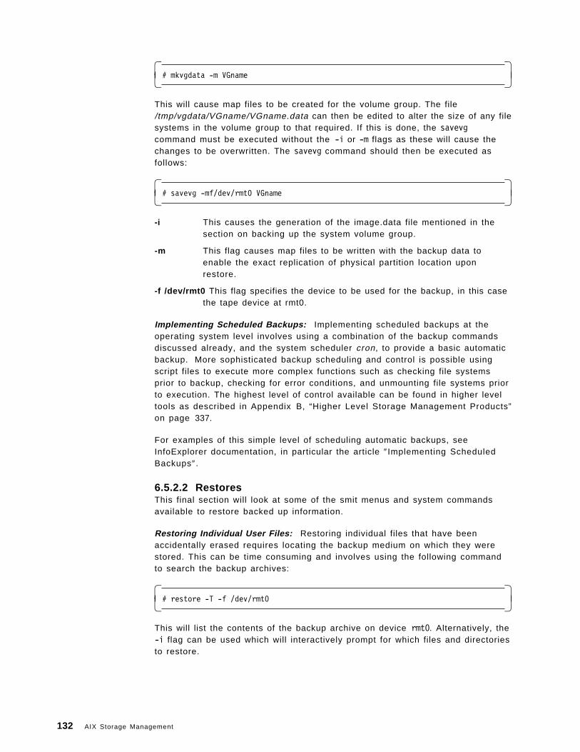
� �# mkvgdata -m VGname� �
This will cause map files to be created for the volume group. The file/tmp/vgdata/VGname/VGname.data can then be edited to alter the size of any filesystems in the volume group to that required. If this is done, the savevgcommand must be executed without the -i or -m flags as these will cause thechanges to be overwritten. The savevg command should then be executed asfollows:
� �# savevg -mf/dev/rmt0 VGname� �
-i This causes the generation of the image.data file mentioned in thesection on backing up the system volume group.
-m This flag causes map files to be written with the backup data toenable the exact replication of physical partition location uponrestore.
-f /dev/rmt0 This flag specifies the device to be used for the backup, in this casethe tape device at rmt0.
Implementing Scheduled Backups: Implementing scheduled backups at theoperating system level involves using a combination of the backup commandsdiscussed already, and the system scheduler cron, to provide a basic automaticbackup. More sophisticated backup scheduling and control is possible usingscript files to execute more complex functions such as checking file systemsprior to backup, checking for error conditions, and unmounting file systems priorto execution. The highest level of control available can be found in higher leveltools as described in Appendix B, “Higher Level Storage Management Products”on page 337.
For examples of this simple level of scheduling automatic backups, seeInfoExplorer documentation, in particular the article ″Implementing ScheduledBackups″.
6.5.2.2 RestoresThis final section will look at some of the smit menus and system commandsavailable to restore backed up information.
Restoring Individual User Files: Restoring individual files that have beenaccidentally erased requires locating the backup medium on which they werestored. This can be time consuming and involves using the following commandto search the backup archives:
� �# restore -T -f /dev/rmt0� �
This will list the contents of the backup archive on device rmt0. Alternatively, the-i flag can be used which will interactively prompt for which files and directoriesto restore.
132 AIX Storage Management
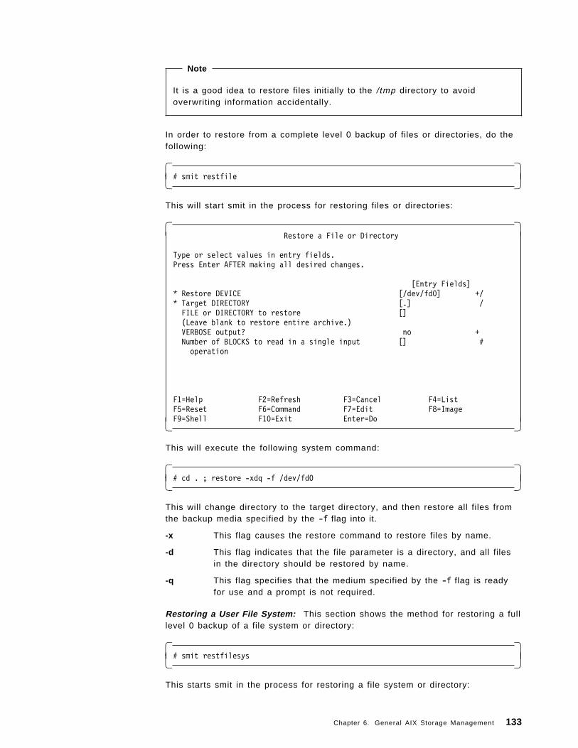
Note
It is a good idea to restore files initially to the / tmp directory to avoidoverwriting information accidentally.
In order to restore from a complete level 0 backup of files or directories, do thefollowing:
� �# smit restfile� �
This will start smit in the process for restoring files or directories:
� �Restore a File or Directory
Type or select values in entry fields.Press Enter AFTER making all desired changes.
[Entry Fields]* Restore DEVICE [/dev/fd0] +/* Target DIRECTORY [.] /FILE or DIRECTORY to restore [](Leave blank to restore entire archive.)VERBOSE output? no +Number of BLOCKS to read in a single input [] #operation
F1=Help F2=Refresh F3=Cancel F4=ListF5=Reset F6=Command F7=Edit F8=ImageF9=Shell F10=Exit Enter=Do� �
This will execute the following system command:
� �# cd . ; restore -xdq -f /dev/fd0� �
This will change directory to the target directory, and then restore all files fromthe backup media specified by the -f flag into it.
-x This flag causes the restore command to restore files by name.
-d This flag indicates that the file parameter is a directory, and all filesin the directory should be restored by name.
-q This flag specifies that the medium specified by the -f flag is readyfor use and a prompt is not required.
Restoring a User File System: This section shows the method for restoring a fulllevel 0 backup of a file system or directory:
� �# smit restfilesys� �
This starts smit in the process for restoring a file system or directory:
Chapter 6. General AIX Storage Management 133
� �Restore a Filesystem
Type or select values in entry fields.Press Enter AFTER making all desired changes.
[Entry Fields]* Restore DEVICE [/dev/fd0] +/* Target DIRECTORY [.] /VERBOSE output? yes +Number of BLOCKS to read in a single input [] #operation
F1=Help F2=Refresh F3=Cancel F4=ListF5=Reset F6=Command F7=Edit F8=ImageF9=Shell F10=Exit Enter=Do� �
This causes the following command to be executed:
� �# cd . ; restore -rq -f /dev/rmt0 -v� �
This changes directory to the target directory and restores a complete filesystem. The file parameter would be ignored in this case, even if included.
-r This flag specifies that a whole file system is to be restored.
-q This flag specifies that the media is ready for reading and a prompt isnot required.
-f This flag indicates the media device to be read from (the tape deviceat rmt0 in this case).
-v This flag shows more information about the restore process, such asfile sizes.
Restoring a User Volume Group: In order to restore an entire user volumegroup, do the following:
� �# smit restvg� �
This starts smit in the process for remaking a volume group:
134 AIX Storage Management
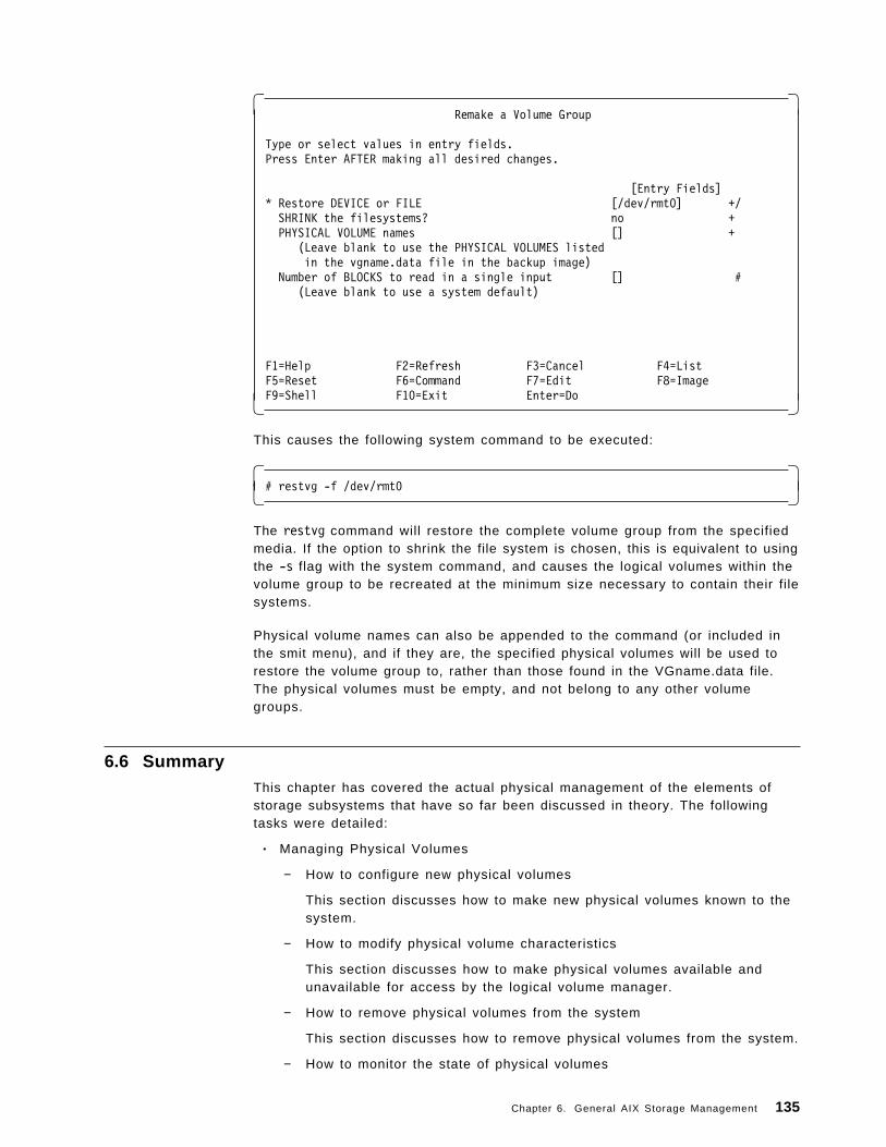
� �Remake a Volume Group
Type or select values in entry fields.Press Enter AFTER making all desired changes.
[Entry Fields]* Restore DEVICE or FILE [/dev/rmt0] +/SHRINK the filesystems? no +PHYSICAL VOLUME names [] +
(Leave blank to use the PHYSICAL VOLUMES listedin the vgname.data file in the backup image)
Number of BLOCKS to read in a single input [] #(Leave blank to use a system default)
F1=Help F2=Refresh F3=Cancel F4=ListF5=Reset F6=Command F7=Edit F8=ImageF9=Shell F10=Exit Enter=Do� �
This causes the following system command to be executed:
� �# restvg -f /dev/rmt0� �
The restvg command will restore the complete volume group from the specifiedmedia. If the option to shrink the file system is chosen, this is equivalent to usingthe -s flag with the system command, and causes the logical volumes within thevolume group to be recreated at the minimum size necessary to contain their filesystems.
Physical volume names can also be appended to the command (or included inthe smit menu), and if they are, the specified physical volumes will be used torestore the volume group to, rather than those found in the VGname.data file.The physical volumes must be empty, and not belong to any other volumegroups.
6.6 SummaryThis chapter has covered the actual physical management of the elements ofstorage subsystems that have so far been discussed in theory. The followingtasks were detailed:
• Managing Physical Volumes
− How to configure new physical volumes
This section discusses how to make new physical volumes known to thesystem.
− How to modify physical volume characteristics
This section discusses how to make physical volumes available andunavailable for access by the logical volume manager.
− How to remove physical volumes from the system
This section discusses how to remove physical volumes from the system.
− How to monitor the state of physical volumes
Chapter 6. General AIX Storage Management 135
• Managing Volume Groups
This section discusses how to monitor physical volumes for error conditions.It also looks at finding out what physical volumes are on the system, whichvolume groups they belong to, and what is stored on them.
− How to add new volume groups
This section discusses how to create new volume groups and define theirinitial characteristics.
− How to modify volume group characteristics
This section discusses how to modify the state of volume groups andtheir characteristics. It looks at how to unlock volume groups, how to addphysical volumes to volume groups, and remove physical volumes fromvolume groups.
− How to import and export volume groups
This section discusses how to make volume groups available andunavailable to the system through import and export, for the purposes ofmaintenance or transfer from system to system.
− How to vary on and off volume groups
This section discusses how to make volume groups ready for access bythe logical volume manager, and other processes that wish to accessdata within a volume group.
− How to monitor volume groups
This section discusses monitoring volume groups from the point of viewof listing the volume groups on the system, listing their characteristics,looking at the logical volumes contained within them, and listing thestatus of physical volumes within the volume groups.
• Managing Logical Volumes
− How to add new logical volumes
This section discusses how to create new logical volumes within avolume group.
− How to remove logical volumes
This section discusses how to remove logical volumes from volumegroups.
− How to increase the size of logical volumes
This section discusses how to modify logical volumes in terms ofincreasing their size.
• Managing the Storage Environment
− Performance Management
This section discusses how to maximize performance when creatinglogical volumes and file systems, when modifying them, and through theuse of striping. Reorganizing volume groups to improve performance isalso looked at.
− Availabil ity Management
This section discusses how to maximize availability when creating andmodifying logical volumes through mirroring. Reorganizing volumegroups to improve availability is also looked at.
136 AIX Storage Management
− Disk Space Management
This section discusses how to maximize disk space utilization throughoptions available at file system creation.
• Managing Backup and Restore
− Backup Management
This section discusses how to backup information from the user andsystem perspectives. Backing up user files, directories, file systems, andvolume groups are examined, as well as creating installable systembackups and scheduling backups.
− Restore Management
This section discusses how to restore backed up information. Restoringuser files, directories, file systems and volume groups are examined.
Chapter 6. General AIX Storage Management 137

138 AIX Storage Management
Chapter 7. Storage Management Files and Commands Summary
This chapter provides details of storage management commands and usage.Commands common to AIX Version 3 and AIX Version 4 are covered, as well asthose specific to AIX Version 4. Although common commands are beingreviewed first, they will be initially grouped according to the AIX Version 4 filesetthat they belong to. This will help the reader become more familiar with the AIXVersion 4 environment.
7.1 How to Understand and Use this ChapterTo learn more about a file in an AIX Version 4 environment, it is advisable to firstdetermine the fileset it belongs to, which is discussed in 7.1.1, “Major AIXVersion 4 Filesets Relevant to Storage Management” on page 140. To learnmore about a file in an AIX Version 3 environment, it is helpful to know whatlogical function the file has that corresponds to the AIX Version 4 filesetdescription. Otherwise, refer to each of the four fileset groups in 7.2, “CommonStorage Management Commands Using AIX Version 3 Syntax” on page 141 anduse the criteria in this section to read about a specific file.
As discussed in 7.1.1, “Major AIX Version 4 Filesets Relevant to StorageManagement” on page 140, 7.2, “Common Storage Management CommandsUsing AIX Version 3 Syntax” on page 141 refers to all files in the four majorfileset logical groups. It then advises the reader to check 7.3, “AIX Version 4Specific File Features” on page 159 if necessary.
The files listed in 7.2, “Common Storage Management Commands Using AIXVersion 3 Syntax” on page 141 and 7.3, “AIX Version 4 Specific File Features” onpage 159 are organized in a logical manner according to the fileset that theybelong to. Files in the same fileset are then grouped in the following logicalbreakdown:
1. What part of the installation package they belong to (that is, the usr, root orshare part).
2. Which AIX Version 4 directory path are they in (it is assumed that theproduct bos.compat that includes filesets such as AIX 3.2 to 4.1 CompatibilityLinks has not been installed; the missing links are noted in 7.3, “AIX Version4 Specific File Features” on page 159).
3. Alphabetical order (this ensures that commands that do similar tasks, suchas the ch* commands that change object attributes, are located near eachother in this chapter).
Each file is initially described by a brief statement that includes:
• A comment about the purpose of the file.
• Which of the following categories it belongs to:
− Object file commands
− Shell script commands (Korn shell, Bourne shell or C shell)
− ASCII data file (that can be editted by the systems administrator using atext editor such as the vi editor)
− Other file types
Copyright IBM Corp. 1994 139
There is then a reference to its documentation status which is one of:
• Undocumented
Warning - DANGER - Warning
An undocumented command is usually not required to be used duringsetup or regular operational systems management tasks. Hence, thesecommands should be used with caution. Preferably, the equivalent highlevel command should be used first. For example, to copy a logicalvolume, try to use the documented cplv command before trying to usecopyrawlv.
• Documented
Search in AIX Version 4.1 Hypertext Information Base Library. In particular,refer to the hardcopy or electronic versions of AIX Version 4.1 CommandsReference and AIX Version 3.2 Files Reference for more details and examplesconcerning this file.
Finally, the chapter concludes by mentioning some other useful commands thatare not part of the AIX Version 3 or AIX Version 4 base operating system. It thenshows you examples of how to look at logical volume manager and journaled filesystem information.
7.1.1 Major AIX Version 4 Filesets Relevant to Storage ManagementThe AIX Version 4.1 Installation Guide describes how software is packaged, andreminds us that that the systems administrator needs to consider what functionsare required, and hence what filesets should be installed. The command:
� �# lslpp -l bos.*|pg� �
will provide a list of base operating system filesets that are installed. The majorones discussed in this chapter are:
bos.rte.lvm Logical Volume Manager
bos.rte.filesystem Filesystem Administration
bos.sysmgt.sysbr System Backup and BOS Installation Utilities
bos.rte.archive Archive Commands
All files in these four filesets are referred to in this chapter, and are listed insection 7.2, “Common Storage Management Commands Using AIX Version 3Syntax” on page 141. If a file has significant changes from AIX Version 3, or if itis a new file that has been introduced by AIX Version 4, then a reference is givento look in section 7.3, “AIX Version 4 Specific File Features” on page 159.
Other filesets that contain commands that are relevant to AIX storagemanagement include:
bos.rte.boot Boot Commands
bos.rte.serv_aid Error Log Service Aids
bos.diag.rte Hardware Diagnostics
bos.rte.diag Diagnostics
140 AIX Storage Management
bos.sysmgt.serv_aid Software Error Logging and Dump Service Aids
bos.rte.compare File Compare Commands
bos.rte.methods Device Configuration Methods
bos.sysmgt.quota File System Quota Commands
Only some of the most important files from these filesets that are relevant to AIXstorage management are discussed in this chapter.
The contents of a fileset can be seen from the command:
� �# lslpp -f fileset_name |pg� �
Note that it is easy to find what fileset a file belongs to in an AIX Version 4system, if the filset in question is installed, by using the command:
� �# lslpp -f all|pg� �
and by then using the / search syntax at the colon prompt. For example, to findthat the cplv command belongs to the bos.rte.lvm fileset, type:
� �:/cplv� �
and press the Enter key followed by entering:
� �:-� �
once or twice to move backwards through the output until the fileset nameappears, such as:
� �bos.rte.lvm 4.1.0.0 /usr/lib/liblvm.a� �
7.2 Common Storage Management Commands Using AIX Version 3 SyntaxThis section looks at the AIX Version 3 commands.
7.2.1 Using Logical Volume Manager FilesThe following commands are logical volume manager related.
7.2.1.1 Usr Part Files which are in the /usr/sbin Directory.allocp allocp is an object file command that is used to generate an
allocation map that is required when a logical volume is created,extended, reduced or removed.
It is an undocumented command whose usage is:
allocp: [-i LVid] [-t Type] [-c Copies][-s Size] [-k] [-u UpperBound>][-e InterPolicy] [-a InterPolicy]
Chapter 7. Storage Management Files and Commands Summary 141
cfgvg cfgvg is a Bourne shell script command that is called by /etc/rc tovaryon volume groups that have the auto-varyon flag set.
It is an undocumented command that requires no flags.
chlv chlv is a Bourne shell script command that changes only thecharacteristics of a logical volume.
It is a documented command whose usage is:
chlv -n NewLVname LVnamechlv [-a IntraPolicy] [-e InterPolicy] [-L Label] [-u UpperBound]
[-s Strict] [-b BadBlocks] [-d Schedule] [-p Permission][-r Relocate] [-t Type] [-w MirrorWriteConsistency][-v Verify] [-x MaxLPs] LVname...
chps chps is an object file command that changes the attributes of apaging space.
It is a documented command whose usage is:
chps [-s NewLPs] [-a {y|n}] Psname
chpv chpv is a Bourne shell script command that changes thecharacteristics of a physical volume.
It is a documented command whose usage is:
chpv { -a Allocation | -v Availability } PVname
chvg chvg is a Bourne shell script command that changes thecharacteristics of a volume group.
It is a documented command whose usage is:
chvg [-a Auto on] [-Q quorum] VGname...
Note that there is a new flag available, -u in AIX Version 4. Pleaserefer to the entry for chvg in 7.3, “AIX Version 4 Specific FileFeatures” on page 159.
copyrawlv copyrawlv is an object file command that is used by cplv to do theactual copying on disk.
Extreme caution is required if this executable is used by thesystems administrator The strings command suggests thatcopyrawlv does not contain any built in syntax advice and hence isnot likely to be designed to used manually. However, as anexample, after some necessary set up work, cplv uses thiscommand as follows:
# Copy one lv to another.copyrawlv /dev/sRawLVName /dev/dRawLVName Size
Where sRawLVName is the source logical volume, dRawLVName is thedestination, and Size is the size.
cplv cplv is a Bourne shell script command that copies a logical volume.
It is a documented command whose usage is:
cplv [-v VGname] [-y NewName | -Y Prefix] SourceLVcplv -e [-f] DestinationLV SourceLV.
exportvg exportvg is a Bourne shell script command that exports thedefinition of a volume group.
It is a documented command whose usage is:
142 AIX Storage Management
exportvg VGname
Note that this command does not change any volume groupconfiguration information on any of the disks that belong to it, butthe command only removes all configuration information about thevolume group (and any associated journalled file systems), from thesystem on which the exportvg is executed.
extendlv extendlv is a Bourne shell script command that extends the size ofa logical volume.
It is a documented command whose usage is:
extendlv [-a IntraPolicy] [-e InterPolicy] [-m MapFile][-s Strict] [-u UpperBound] LVname NumberOfLPs [PVname...]
extendvg extendvg is a Bourne shell script command that extends a volumegroup by adding a physical volume.
It is a documented command whose usage is:
extendvg [-f] VGname PVname...
getlvcb getlvcb is an object file command that gets information about alogical volume from the logical volume control block.
It is an undocumented command whose usage is: suggested byother high level shell scripts, such as updatelv, that call it. Thisscript tells us that the syntax is like:
getlvcb -aceLrsSPtu LVNamegetlvcb -f LVName
Please refer to the entry for getlvcb in 7.3, “AIX Version 4 SpecificFile Features” on page 159.
getlvname cfgvg is an object file command that generates or checks a logicalvolume name.
It is an undocumented command whose usage is:
getlvname [-Y Prefix] [-n LVname] [Type]
getlvodm getlvodm is an object file command that obtains volume group andlogical volume information from the ODM.
It is an undocumented command whose usage is:
getlvodm [-a LVdescript] [-B LVdesrcript] [-b LVid][-cVid] [-C] [-d VGdescript][-e LVid] [-F] [-g PVid] [-h][-j PVdescript] [-k] [-L VGdescript][-l LVdescript] [-m LVid] [-p PVdescript][-r LVid] [-s VGdescript] [-t VGid][-u VGdescript] [-v VGdescript] [-w VGid][-y LVid]
Please refer to the entry for getlvodm in 7.3, “AIX Version 4 SpecificFile Features” on page 159.
getvgname getvgname is an object file command that is used to return a newunused volume group name.
It is an undocumented command whose usage is:
getvgname [-n VGname]
Chapter 7. Storage Management Files and Commands Summary 143
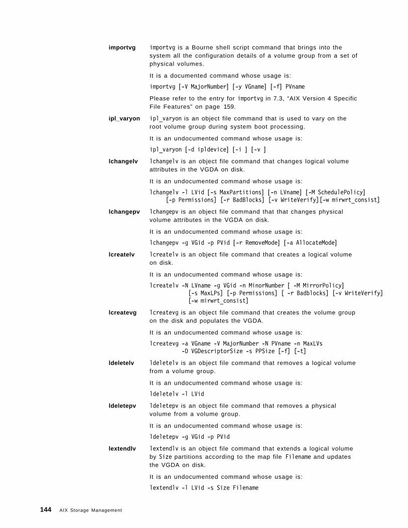
importvg importvg is a Bourne shell script command that brings into thesystem all the configuration details of a volume group from a set ofphysical volumes.
It is a documented command whose usage is:
importvg [-V MajorNumber] [-y VGname] [-f] PVname
Please refer to the entry for importvg in 7.3, “AIX Version 4 SpecificFile Features” on page 159.
ipl_varyon ipl_varyon is an object file command that is used to vary on theroot volume group during system boot processing.
It is an undocumented command whose usage is:
ipl_varyon [-d ipldevice] [-i ] [-v ]
lchangelv lchangelv is an object file command that changes logical volumeattributes in the VGDA on disk.
It is an undocumented command whose usage is:
lchangelv -l LVid [-s MaxPartitions] [-n LVname] [-M SchedulePolicy][-p Permissions] [-r BadBlocks] [-v WriteVerify][-w mirwrt_consist]
lchangepv lchangepv is an object file command that that changes physicalvolume attributes in the VGDA on disk.
It is an undocumented command whose usage is:
lchangepv -g VGid -p PVid [-r RemoveMode] [-a AllocateMode]
lcreatelv lcreatelv is an object file command that creates a logical volumeon disk.
It is an undocumented command whose usage is:
lcreatelv -N LVname -g VGid -n MinorNumber [ -M MirrorPolicy][-s MaxLPs] [-p Permissions] [ -r Badblocks] [-v WriteVerify][-w mirwrt_consist]
lcreatevg lcreatevg is an object file command that creates the volume groupon the disk and populates the VGDA.
It is an undocumented command whose usage is:
lcreatevg -a VGname -V MajorNumber -N PVname -n MaxLVs-D VGDescriptorSize -s PPSize [-f] [-t]
ldeletelv ldeletelv is an object file command that removes a logical volumefrom a volume group.
It is an undocumented command whose usage is:
ldeletelv -l LVid
ldeletepv ldeletepv is an object file command that removes a physicalvolume from a volume group.
It is an undocumented command whose usage is:
ldeletepv -g VGid -p PVid
lextendlv lextendlv is an object file command that extends a logical volumeby Size partitions according to the map file Filename and updatesthe VGDA on disk.
It is an undocumented command whose usage is:
lextendlv -l LVid -s Size Filename
144 AIX Storage Management
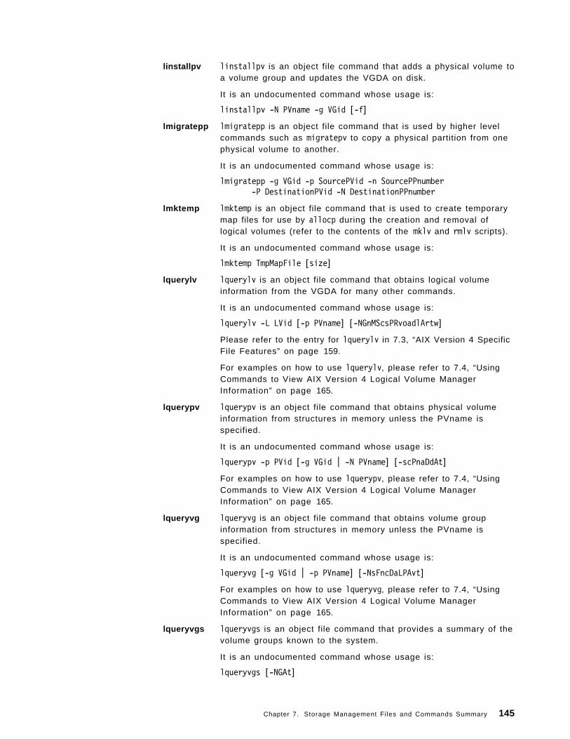
linstallpv linstallpv is an object file command that adds a physical volume toa volume group and updates the VGDA on disk.
It is an undocumented command whose usage is:
linstallpv -N PVname -g VGid [-f]
lmigratepp lmigratepp is an object file command that is used by higher levelcommands such as migratepv to copy a physical partition from onephysical volume to another.
It is an undocumented command whose usage is:
lmigratepp -g VGid -p SourcePVid -n SourcePPnumber-P DestinationPVid -N DestinationPPnumber
lmktemp lmktemp is an object file command that is used to create temporarymap files for use by allocp during the creation and removal oflogical volumes (refer to the contents of the mklv and rmlv scripts).
It is an undocumented command whose usage is:
lmktemp TmpMapFile [size]
lquerylv lquerylv is an object file command that obtains logical volumeinformation from the VGDA for many other commands.
It is an undocumented command whose usage is:
lquerylv -L LVid [-p PVname] [-NGnMScsPRvoadlArtw]
Please refer to the entry for lquerylv in 7.3, “AIX Version 4 SpecificFile Features” on page 159.
For examples on how to use lquerylv, please refer to 7.4, “UsingCommands to View AIX Version 4 Logical Volume ManagerInformation” on page 165.
lquerypv lquerypv is an object file command that obtains physical volumeinformation from structures in memory unless the PVname isspecified.
It is an undocumented command whose usage is:
lquerypv -p PVid [-g VGid | -N PVname] [-scPnaDdAt]
For examples on how to use lquerypv, please refer to 7.4, “UsingCommands to View AIX Version 4 Logical Volume ManagerInformation” on page 165.
lqueryvg lqueryvg is an object file command that obtains volume groupinformation from structures in memory unless the PVname isspecified.
It is an undocumented command whose usage is:
lqueryvg [-g VGid | -p PVname] [-NsFncDaLPAvt]
For examples on how to use lqueryvg, please refer to 7.4, “UsingCommands to View AIX Version 4 Logical Volume ManagerInformation” on page 165.
lqueryvgs lqueryvgs is an object file command that provides a summary of thevolume groups known to the system.
It is an undocumented command whose usage is:
lqueryvgs [-NGAt]
Chapter 7. Storage Management Files and Commands Summary 145
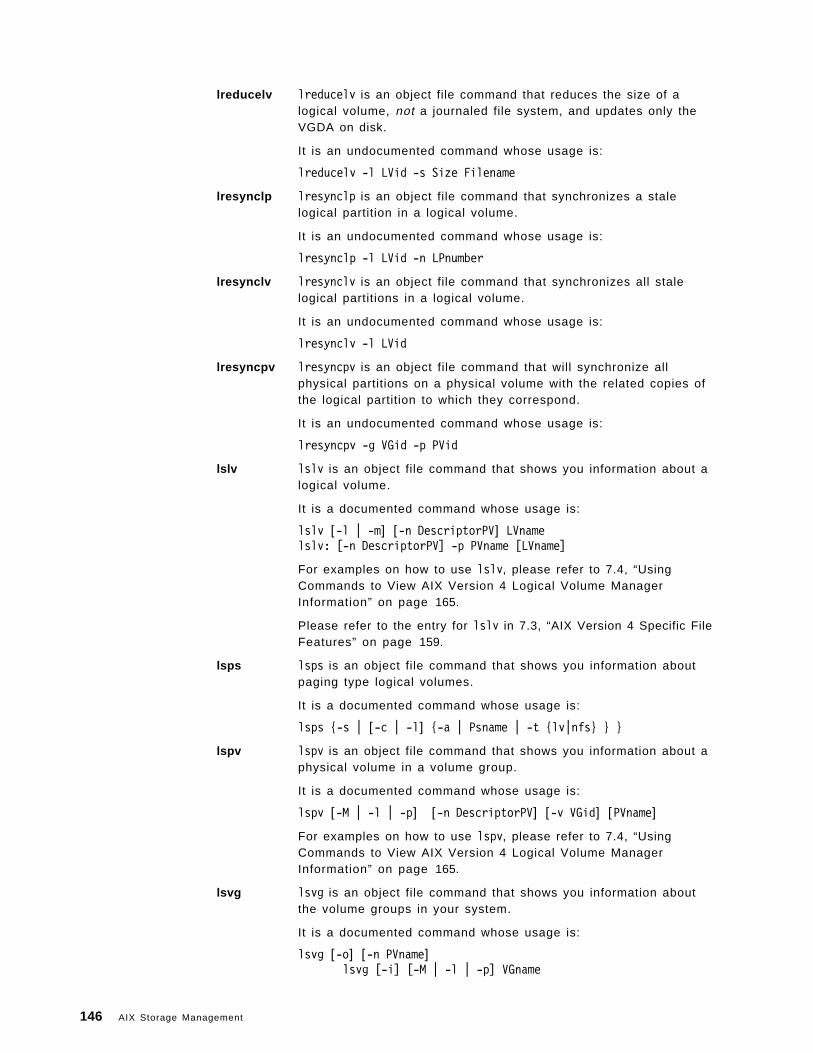
lreducelv lreducelv is an object file command that reduces the size of alogical volume, not a journaled file system, and updates only theVGDA on disk.
It is an undocumented command whose usage is:
lreducelv -l LVid -s Size Filename
lresynclp lresynclp is an object file command that synchronizes a stalelogical partition in a logical volume.
It is an undocumented command whose usage is:
lresynclp -l LVid -n LPnumber
lresynclv lresynclv is an object file command that synchronizes all stalelogical partitions in a logical volume.
It is an undocumented command whose usage is:
lresynclv -l LVid
lresyncpv lresyncpv is an object file command that will synchronize allphysical partitions on a physical volume with the related copies ofthe logical partition to which they correspond.
It is an undocumented command whose usage is:
lresyncpv -g VGid -p PVid
lslv lslv is an object file command that shows you information about alogical volume.
It is a documented command whose usage is:
lslv [-l | -m] [-n DescriptorPV] LVnamelslv: [-n DescriptorPV] -p PVname [LVname]
For examples on how to use lslv, please refer to 7.4, “UsingCommands to View AIX Version 4 Logical Volume ManagerInformation” on page 165.
Please refer to the entry for lslv in 7.3, “AIX Version 4 Specific FileFeatures” on page 159.
lsps lsps is an object file command that shows you information aboutpaging type logical volumes.
It is a documented command whose usage is:
lsps {-s | [-c | -l] {-a | Psname | -t {lv|nfs} } }
lspv lspv is an object file command that shows you information about aphysical volume in a volume group.
It is a documented command whose usage is:
lspv [-M | -l | -p] [-n DescriptorPV] [-v VGid] [PVname]
For examples on how to use lspv, please refer to 7.4, “UsingCommands to View AIX Version 4 Logical Volume ManagerInformation” on page 165.
lsvg lsvg is an object file command that shows you information aboutthe volume groups in your system.
It is a documented command whose usage is:
lsvg [-o] [-n PVname]lsvg [-i] [-M | -l | -p] VGname
146 AIX Storage Management
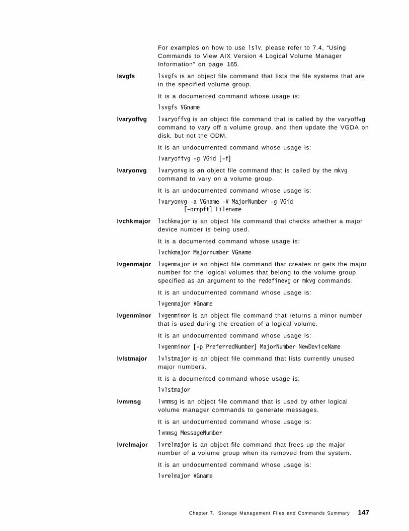
For examples on how to use lslv, please refer to 7.4, “UsingCommands to View AIX Version 4 Logical Volume ManagerInformation” on page 165.
lsvgfs lsvgfs is an object file command that lists the file systems that arein the specified volume group.
It is a documented command whose usage is:
lsvgfs VGname
lvaryoffvg lvaryoffvg is an object file command that is called by the varyoffvgcommand to vary off a volume group, and then update the VGDA ondisk, but not the ODM.
It is an undocumented command whose usage is:
lvaryoffvg -g VGid [-f]
lvaryonvg lvaryonvg is an object file command that is called by the mkvgcommand to vary on a volume group.
It is an undocumented command whose usage is:
lvaryonvg -a VGname -V MajorNumber -g VGid[-ornpft] Filename
lvchkmajor lvchkmajor is an object file command that checks whether a majordevice number is being used.
It is a documented command whose usage is:
lvchkmajor Majornumber VGname
lvgenmajor lvgenmajor is an object file command that creates or gets the majornumber for the logical volumes that belong to the volume groupspecified as an argument to the redefinevg or mkvg commands.
It is an undocumented command whose usage is:
lvgenmajor VGname
lvgenminor lvgenminor is an object file command that returns a minor numberthat is used during the creation of a logical volume.
It is an undocumented command whose usage is:
lvgenminor [-p PreferredNumber] MajorNumber NewDeviceName
lvlstmajor lvlstmajor is an object file command that lists currently unusedmajor numbers.
It is a documented command whose usage is:
lvlstmajor
lvmmsg lvmmsg is an object file command that is used by other logicalvolume manager commands to generate messages.
It is an undocumented command whose usage is:
lvmmsg MessageNumber
lvrelmajor lvrelmajor is an object file command that frees up the majornumber of a volume group when its removed from the system.
It is an undocumented command whose usage is:
lvrelmajor VGname
Chapter 7. Storage Management Files and Commands Summary 147
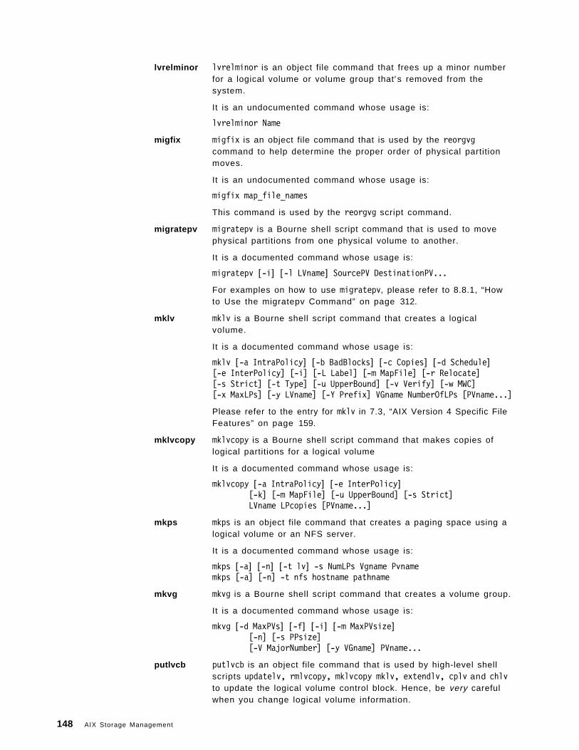
lvrelminor lvrelminor is an object file command that frees up a minor numberfor a logical volume or volume group that′s removed from thesystem.
It is an undocumented command whose usage is:
lvrelminor Name
migfix migfix is an object file command that is used by the reorgvgcommand to help determine the proper order of physical partitionmoves.
It is an undocumented command whose usage is:
migfix map_file_names
This command is used by the reorgvg script command.
migratepv migratepv is a Bourne shell script command that is used to movephysical partitions from one physical volume to another.
It is a documented command whose usage is:
migratepv [-i] [-l LVname] SourcePV DestinationPV...
For examples on how to use migratepv, please refer to 8.8.1, “Howto Use the migratepv Command” on page 312.
mklv mklv is a Bourne shell script command that creates a logicalvolume.
It is a documented command whose usage is:
mklv [-a IntraPolicy] [-b BadBlocks] [-c Copies] [-d Schedule][-e InterPolicy] [-i] [-L Label] [-m MapFile] [-r Relocate][-s Strict] [-t Type] [-u UpperBound] [-v Verify] [-w MWC][-x MaxLPs] [-y LVname] [-Y Prefix] VGname NumberOfLPs [PVname...]
Please refer to the entry for mklv in 7.3, “AIX Version 4 Specific FileFeatures” on page 159.
mklvcopy mklvcopy is a Bourne shell script command that makes copies oflogical partitions for a logical volume
It is a documented command whose usage is:
mklvcopy [-a IntraPolicy] [-e InterPolicy][-k] [-m MapFile] [-u UpperBound] [-s Strict]LVname LPcopies [PVname...]
mkps mkps is an object file command that creates a paging space using alogical volume or an NFS server.
It is a documented command whose usage is:
mkps [-a] [-n] [-t lv] -s NumLPs Vgname Pvnamemkps [-a] [-n] -t nfs hostname pathname
mkvg mkvg is a Bourne shell script command that creates a volume group.
It is a documented command whose usage is:
mkvg [-d MaxPVs] [-f] [-i] [-m MaxPVsize][-n] [-s PPsize][-V MajorNumber] [-y VGname] PVname...
putlvcb putlvcb is an object file command that is used by high-level shellscripts updatelv, rmlvcopy, mklvcopy mklv, extendlv, cplv and chlvto update the logical volume control block. Hence, be very carefulwhen you change logical volume information.
148 AIX Storage Management
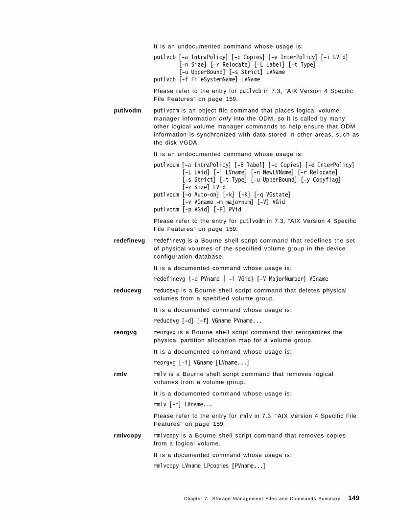
It is an undocumented command whose usage is:
putlvcb [-a IntraPolicy] [-c Copies] [-e InterPolicy] [-i LVid][-n Size] [-r Relocate] [-L Label] [-t Type][-u UpperBound] [-s Strict] LVName
putlvcb [-f FileSystemName] LVName
Please refer to the entry for putlvcb in 7.3, “AIX Version 4 SpecificFile Features” on page 159.
putlvodm putlvodm is an object file command that places logical volumemanager information only into the ODM, so it is called by manyother logical volume manager commands to help ensure that ODMinformation is synchronized with data stored in other areas, such asthe disk VGDA.
It is an undocumented command whose usage is:
putlvodm [-a IntraPolicy] [-B label] [-c Copies] [-e InterPolicy][-L LVid] [-l LVname] [-n NewLVName] [-r Relocate][-s Strict] [-t Type] [-u UpperBound] [-y Copyflag][-z Size] LVid
putlvodm [-o Auto-on] [-k] [-K] [-q VGstate][-v VGname -m majornum] [-V] VGid
putlvodm [-p VGid] [-P] PVid
Please refer to the entry for putlvodm in 7.3, “AIX Version 4 SpecificFile Features” on page 159.
redefinevg redefinevg is a Bourne shell script command that redefines the setof physical volumes of the specified volume group in the deviceconfiguration database.
It is a documented command whose usage is:
redefinevg {-d PVname | -i VGid} [-V MajorNumber] VGname
reducevg reducevg is a Bourne shell script command that deletes physicalvolumes from a specified volume group.
It is a documented command whose usage is:
reducevg [-d] [-f] VGname PVname...
reorgvg reorgvg is a Bourne shell script command that reorganizes thephysical partition allocation map for a volume group.
It is a documented command whose usage is:
reorgvg [-i] VGname [LVname...]
rmlv rmlv is a Bourne shell script command that removes logicalvolumes from a volume group.
It is a documented command whose usage is:
rmlv [-f] LVname...
Please refer to the entry for rmlv in 7.3, “AIX Version 4 Specific FileFeatures” on page 159.
rmlvcopy rmlvcopy is a Bourne shell script command that removes copiesfrom a logical volume.
It is a documented command whose usage is:
rmlvcopy LVname LPcopies [PVname...]
Chapter 7. Storage Management Files and Commands Summary 149
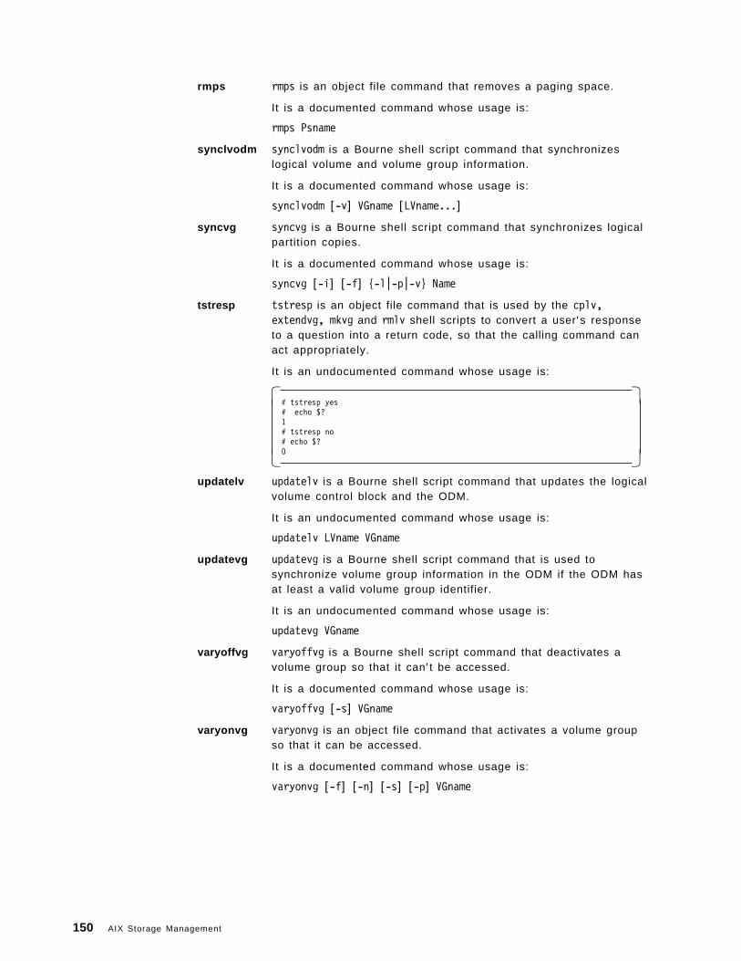
rmps rmps is an object file command that removes a paging space.
It is a documented command whose usage is:
rmps Psname
synclvodm synclvodm is a Bourne shell script command that synchronizeslogical volume and volume group information.
It is a documented command whose usage is:
synclvodm [-v] VGname [LVname...]
syncvg syncvg is a Bourne shell script command that synchronizes logicalpartition copies.
It is a documented command whose usage is:
syncvg [-i] [-f] {-l|-p|-v} Name
tstresp tstresp is an object file command that is used by the cplv,extendvg, mkvg and rmlv shell scripts to convert a user′s responseto a question into a return code, so that the calling command canact appropriately.
It is an undocumented command whose usage is:
� �# tstresp yes# echo $?1# tstresp no# echo $?0� �
updatelv updatelv is a Bourne shell script command that updates the logicalvolume control block and the ODM.
It is an undocumented command whose usage is:
updatelv LVname VGname
updatevg updatevg is a Bourne shell script command that is used tosynchronize volume group information in the ODM if the ODM hasat least a valid volume group identifier.
It is an undocumented command whose usage is:
updatevg VGname
varyoffvg varyoffvg is a Bourne shell script command that deactivates avolume group so that it can′ t be accessed.
It is a documented command whose usage is:
varyoffvg [-s] VGname
varyonvg varyonvg is an object file command that activates a volume groupso that it can be accessed.
It is a documented command whose usage is:
varyonvg [-f] [-n] [-s] [-p] VGname
150 AIX Storage Management
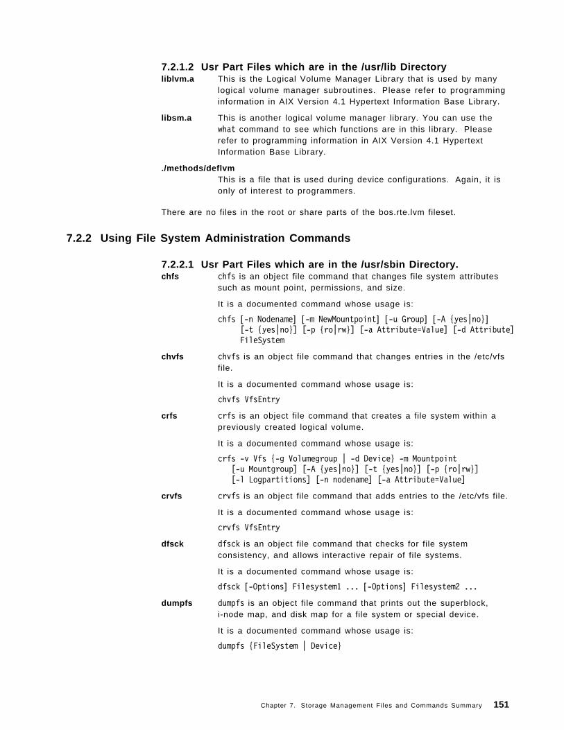
7.2.1.2 Usr Part Files which are in the /usr/lib Directoryliblvm.a This is the Logical Volume Manager Library that is used by many
logical volume manager subroutines. Please refer to programminginformation in AIX Version 4.1 Hypertext Information Base Library.
libsm.a This is another logical volume manager library. You can use thewhat command to see which functions are in this library. Pleaserefer to programming information in AIX Version 4.1 HypertextInformation Base Library.
./methods/deflvmThis is a file that is used during device configurations. Again, it isonly of interest to programmers.
There are no files in the root or share parts of the bos.rte.lvm fileset.
7.2.2 Using File System Administration Commands
7.2.2.1 Usr Part Files which are in the /usr/sbin Directory.chfs chfs is an object file command that changes file system attributes
such as mount point, permissions, and size.
It is a documented command whose usage is:
chfs [-n Nodename] [-m NewMountpoint] [-u Group] [-A {yes|no}][-t {yes|no}] [-p {ro|rw}] [-a Attribute=Value] [-d Attribute]FileSystem
chvfs chvfs is an object file command that changes entries in the /etc/vfsfile.
It is a documented command whose usage is:
chvfs VfsEntry
crfs crfs is an object file command that creates a file system within apreviously created logical volume.
It is a documented command whose usage is:
crfs -v Vfs {-g Volumegroup | -d Device} -m Mountpoint[-u Mountgroup] [-A {yes|no}] [-t {yes|no}] [-p {ro|rw}][-l Logpartitions] [-n nodename] [-a Attribute=Value]
crvfs crvfs is an object file command that adds entries to the /etc/vfs file.
It is a documented command whose usage is:
crvfs VfsEntry
dfsck dfsck is an object file command that checks for file systemconsistency, and allows interactive repair of file systems.
It is a documented command whose usage is:
dfsck [-Options] Filesystem1 ... [-Options] Filesystem2 ...
dumpfs dumpfs is an object file command that prints out the superblock,i-node map, and disk map for a file system or special device.
It is a documented command whose usage is:
dumpfs {FileSystem | Device}
Chapter 7. Storage Management Files and Commands Summary 151
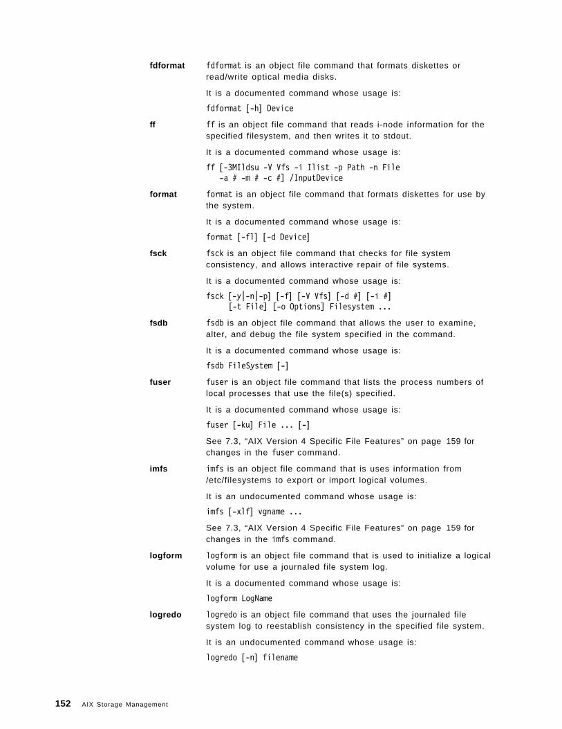
fdformat fdformat is an object file command that formats diskettes orread/write optical media disks.
It is a documented command whose usage is:
fdformat [-h] Device
ff ff is an object file command that reads i-node information for thespecified filesystem, and then writes it to stdout.
It is a documented command whose usage is:
ff [-3MIldsu -V Vfs -i Ilist -p Path -n File-a # -m # -c #] /InputDevice
format format is an object file command that formats diskettes for use bythe system.
It is a documented command whose usage is:
format [-fl] [-d Device]
fsck fsck is an object file command that checks for file systemconsistency, and allows interactive repair of file systems.
It is a documented command whose usage is:
fsck [-y|-n|-p] [-f] [-V Vfs] [-d #] [-i #][-t File] [-o Options] Filesystem ...
fsdb fsdb is an object file command that allows the user to examine,alter, and debug the file system specified in the command.
It is a documented command whose usage is:
fsdb FileSystem [-]
fuser fuser is an object file command that lists the process numbers oflocal processes that use the file(s) specified.
It is a documented command whose usage is:
fuser [-ku] File ... [-]
See 7.3, “AIX Version 4 Specific File Features” on page 159 forchanges in the fuser command.
imfs imfs is an object file command that is uses information from/etc/filesystems to export or import logical volumes.
It is an undocumented command whose usage is:
imfs [-xlf] vgname ...
See 7.3, “AIX Version 4 Specific File Features” on page 159 forchanges in the imfs command.
logform logform is an object file command that is used to initialize a logicalvolume for use a journaled file system log.
It is a documented command whose usage is:
logform LogName
logredo logredo is an object file command that uses the journaled filesystem log to reestablish consistency in the specified file system.
It is an undocumented command whose usage is:
logredo [-n] filename
152 AIX Storage Management
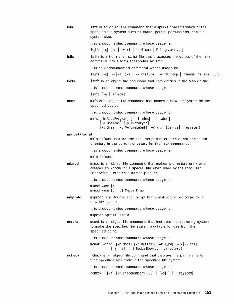
lsfs lsfs is an object file command that displays characteristics of thespecified file system such as mount points, permissions, and filesystem size.
It is a documented command whose usage is:
lsjfs [-q] {-a | -v Vfs| -u Group | Filesystem ...}
lsjfs lsjfs is a Korn shell script file that processes the output of the lsfscommand into a form acceptable by smit.
It is an undocumented command whose usage is:
lsjfs [-q] [-c|-l] {-a | -v vfstype | -u mtgroup | fsname [fsname ...]}
lsvfs lsvfs is an object file command that lists entries in the /etc/vfs file.
It is a documented command whose usage is:
lsvfs {-a | Vfsname}
mkfs mkfs is an object file command that makes a new file system on thespecified device.
It is a documented command whose usage is:
mkfs [-b BootProgram] [-i Inodes] [-l Label][-o Options] [-p Prototype][-s Size] [-v VolumeLabel] [-V vfs] {Device|Filesystem}
mklost+foundmklost+found is a Bourne shell script that creates a lost and founddirectory in the current directory for the fsck command.
It is a documented command whose usage is:
mklost+found
mknod mknod is an object file command that makes a directory entry andcreates an i-node for a special file when used by the root user.Otherwise it creates a named pipeline.
It is a documented command whose usage is:
mknod Name {p}mknod Name {b | p} Major Minor
mkproto mkproto is a Bourne shell script that constructs a prototype for anew file system.
It is a documented command whose usage is:
mkproto Special Proto
mount mount is an object file command that instructs the operating systemto make the specified file system available for use from thespecified point.
It is a documented command whose usage is:
mount [-fipr] [-n Node] [-o Options] [-t Type] [-{v|V} Vfs][-a | all | [[Node:]Device] [Directory]]
ncheck ncheck is an object file command that displays the path name forfiles specified by i-node in the specified file system.
It is a documented command whose usage is:
ncheck [ [-a] [-i InodeNumbers ...] | [-s] ] [FileSystem]
Chapter 7. Storage Management Files and Commands Summary 153
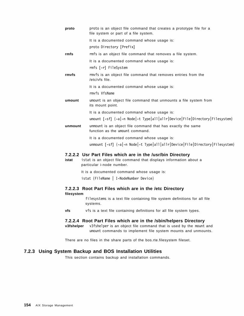
proto proto is an object file command that creates a prototype file for afile system or part of a file system.
It is a documented command whose usage is:
proto Directory [Prefix]
rmfs rmfs is an object file command that removes a file system.
It is a documented command whose usage is:
rmfs [-r] FileSystem
rmvfs rmvfs is an object file command that removes entries from the/etc/vfs file.
It is a documented command whose usage is:
rmvfs VfsName
umount umount is an object file command that unmounts a file system fromits mount point.
It is a documented command whose usage is:
umount [-sf] {-a|-n Node|-t Type|all|allr|Device|File|Directory|Filesystem}
unmount unmount is an object file command that has exactly the samefunction as the umount command.
It is a documented command whose usage is:
unmount [-sf] {-a|-n Node|-t Type|all|allr|Device|File|Directory|Filesystem}
7.2.2.2 Usr Part Files which are in the /usr/bin Directoryistat istat is an object file command that displays information about a
particular i-node number.
It is a documented command whose usage is:
istat {FileName | I-NodeNumber Device}
7.2.2.3 Root Part Files which are in the /etc Directoryfilesystem
filesystems is a text file containing file system definitions for all filesystems.
vfs vfs is a text file containing definitions for all file system types.
7.2.2.4 Root Part Files which are in the /sbin/helpers Directoryv3fshelper v3fshelper is an object file command that is used by the mount and
umount commands to implement file system mounts and unmounts.
There are no files in the share parts of the bos.rte.filesystem fileset.
7.2.3 Using System Backup and BOS Installation UtilitiesThis section contains backup and installation commands.
154 AIX Storage Management
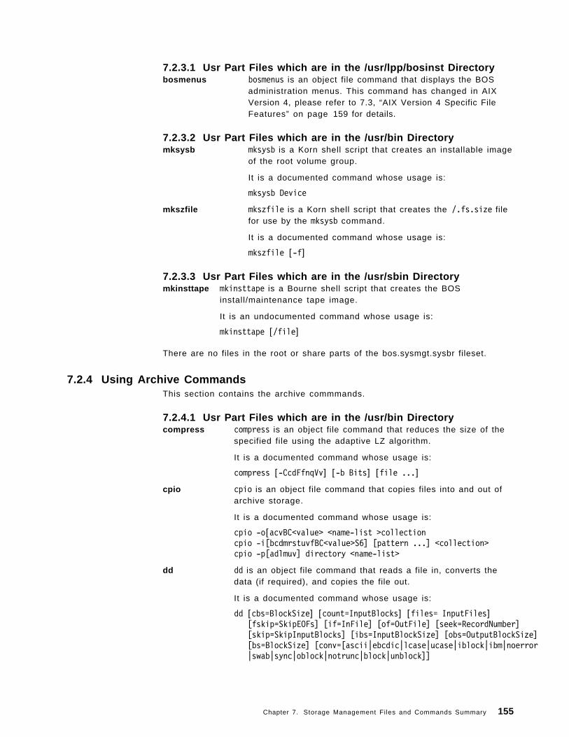
7.2.3.1 Usr Part Files which are in the /usr/lpp/bosinst Directorybosmenus bosmenus is an object file command that displays the BOS
administration menus. This command has changed in AIXVersion 4, please refer to 7.3, “AIX Version 4 Specific FileFeatures” on page 159 for details.
7.2.3.2 Usr Part Files which are in the /usr/bin Directorymksysb mksysb is a Korn shell script that creates an installable image
of the root volume group.
It is a documented command whose usage is:
mksysb Device
mkszfile mkszfile is a Korn shell script that creates the /.fs.size filefor use by the mksysb command.
It is a documented command whose usage is:
mkszfile [-f]
7.2.3.3 Usr Part Files which are in the /usr/sbin Directorymkinsttape mkinsttape is a Bourne shell script that creates the BOS
install/maintenance tape image.
It is an undocumented command whose usage is:
mkinsttape [/file]
There are no files in the root or share parts of the bos.sysmgt.sysbr fileset.
7.2.4 Using Archive CommandsThis section contains the archive commmands.
7.2.4.1 Usr Part Files which are in the /usr/bin Directorycompress compress is an object file command that reduces the size of the
specified file using the adaptive LZ algorithm.
It is a documented command whose usage is:
compress [-CcdFfnqVv] [-b Bits] [file ...]
cpio cpio is an object file command that copies files into and out ofarchive storage.
It is a documented command whose usage is:
cpio -o[acvBC<value> <name-list >collectioncpio -i[bcdmrstuvfBC<value>S6] [pattern ...] <collection>cpio -p[adlmuv] directory <name-list>
dd dd is an object file command that reads a file in, converts thedata (if required), and copies the file out.
It is a documented command whose usage is:
dd [cbs=BlockSize] [count=InputBlocks] [files= InputFiles][fskip=SkipEOFs] [if=InFile] [of=OutFile] [seek=RecordNumber][skip=SkipInputBlocks] [ibs=InputBlockSize] [obs=OutputBlockSize][bs=BlockSize] [conv=[ascii|ebcdic|lcase|ucase|iblock|ibm|noerror|swab|sync|oblock|notrunc|block|unblock]]
Chapter 7. Storage Management Files and Commands Summary 155
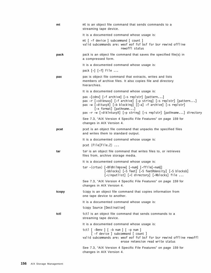
mt mt is an object file command that sends commands to astreaming tape device.
It is a documented command whose usage is:
mt [ -f device ] subcommand [ count ]valid subcommands are: weof eof fsf bsf fsr bsr rewind offline
rewoffl status
pack pack is an object file command that saves the specified file(s) ina compressed form.
It is a documented command whose usage is:
pack [-] [-f] File ...
pax pax is object file command that extracts, writes and listsmembers of archive files. It also copies file and directoryhierarchies.
It is a documented command whose usage is:
pax -[cdnv] [-f archive] [-s replstr] [pattern...]pax -r [-cdiknuvy] [-f archive] [-p string] [-s replstr] [pattern...]pax -w [-dituvyX] [-b blocking] [[-a] -f archive] [-s replstr]
[-x format] [pathname...]pax -r -w [-diklntuvyX] [-p string] [-s replstr] [pathname...] directory
See 7.3, “AIX Version 4 Specific File Features” on page 159 forchanges in AIX Version 4.
pcat pcat is an object file command that unpacks the specified filesand writes them to standard output.
It is a documented command whose usage is:
pcat {File|File.Z} ...
tar tar is an object file command that writes files to, or retrievesfiles from, archive storage media.
It is a documented command whose usage is:
tar -{crtux} [-BFdhilmpsvw] [-num] [-ffile[-num]][-bblocks] [-S feet] [-S feet@density] [-S blocksb][-Linputlist] [-C directory] [-Nblocks] file ...
See 7.3, “AIX Version 4 Specific File Features” on page 159 forchanges in AIX Version 4.
tcopy tcopy is an object file command that copies information fromone tape device to another.
It is a documented command whose usage is:
tcopy Source [Destination]
tctl tctl is an object file command that sends commands to astreaming tape device.
It is a documented command whose usage is:
tctl [ -Benv ] [ -b num ] [ -p num ][ -f device ] subcommand [ count ]
valid subcommands are: weof eof fsf bsf fsr bsr rewind offline rewofflerase retension read write status
See 7.3, “AIX Version 4 Specific File Features” on page 159 forchanges in AIX Version 4.
156 AIX Storage Management
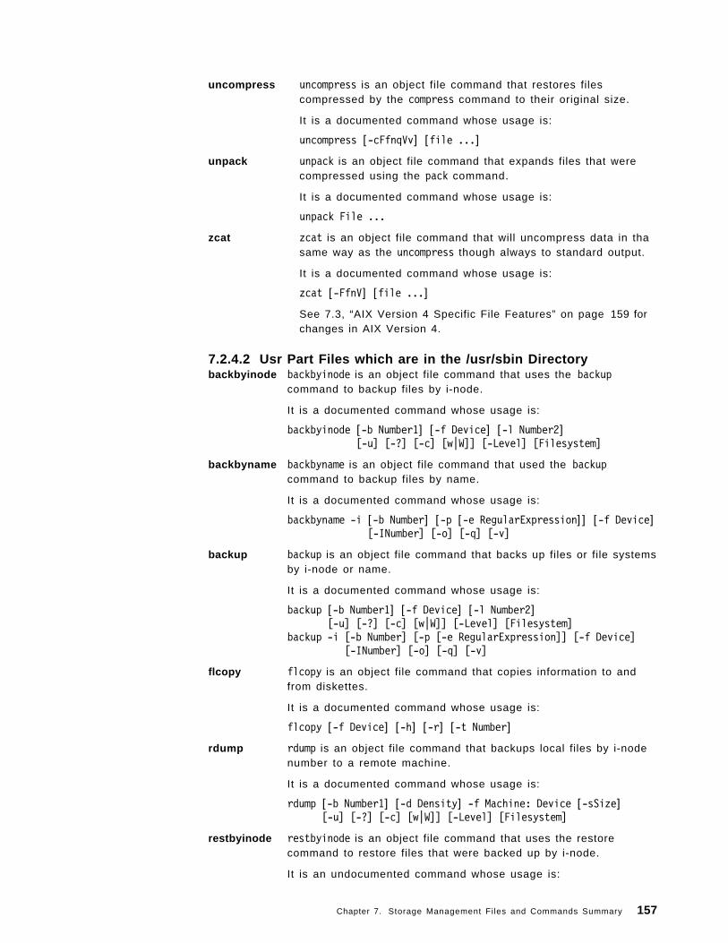
uncompress uncompress is an object file command that restores filescompressed by the compress command to their original size.
It is a documented command whose usage is:
uncompress [-cFfnqVv] [file ...]
unpack unpack is an object file command that expands files that werecompressed using the pack command.
It is a documented command whose usage is:
unpack File ...
zcat zcat is an object file command that will uncompress data in thasame way as the uncompress though always to standard output.
It is a documented command whose usage is:
zcat [-FfnV] [file ...]
See 7.3, “AIX Version 4 Specific File Features” on page 159 forchanges in AIX Version 4.
7.2.4.2 Usr Part Files which are in the /usr/sbin Directorybackbyinode backbyinode is an object file command that uses the backup
command to backup files by i-node.
It is a documented command whose usage is:
backbyinode [-b Number1] [-f Device] [-l Number2][-u] [-?] [-c] [w|W]] [-Level] [Filesystem]
backbyname backbyname is an object file command that used the backupcommand to backup files by name.
It is a documented command whose usage is:
backbyname -i [-b Number] [-p [-e RegularExpression]] [-f Device][-INumber] [-o] [-q] [-v]
backup backup is an object file command that backs up files or file systemsby i-node or name.
It is a documented command whose usage is:
backup [-b Number1] [-f Device] [-l Number2][-u] [-?] [-c] [w|W]] [-Level] [Filesystem]
backup -i [-b Number] [-p [-e RegularExpression]] [-f Device][-INumber] [-o] [-q] [-v]
flcopy flcopy is an object file command that copies information to andfrom diskettes.
It is a documented command whose usage is:
flcopy [-f Device] [-h] [-r] [-t Number]
rdump rdump is an object file command that backups local files by i-nodenumber to a remote machine.
It is a documented command whose usage is:
rdump [-b Number1] [-d Density] -f Machine: Device [-sSize][-u] [-?] [-c] [w|W]] [-Level] [Filesystem]
restbyinode restbyinode is an object file command that uses the restorecommand to restore files that were backed up by i-node.
It is an undocumented command whose usage is:
Chapter 7. Storage Management Files and Commands Summary 157
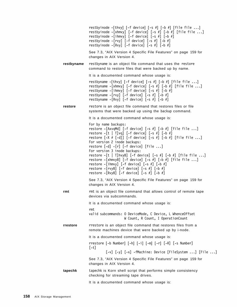
restbyinode -[thvy] [-f device] [-s #] [-b #] [file file ...]restbyinode -[xhmvy] [-f device] [-s #] [-b #] [file file ...]restbyinode -[ihmvy] [-f device] [-s #] [-b #]restbyinode -[rvy] [-f device] [-s #] [-b #]restbyinode -[Rvy] [-f device] [-s #] [-b #]
See 7.3, “AIX Version 4 Specific File Features” on page 159 forchanges in AIX Version 4.
restbyname restbyname is an object file command that uses the restorecommand to restore files that were backed up by name.
It is a documented command whose usage is:
restbyname -[thvy] [-f device] [-s #] [-b #] [file file ...]restbyname -[xhmvy] [-f device] [-s #] [-b #] [file file ...]restbyname -[ihmvy] [-f device] [-s #] [-b #]restbyname -[rvy] [-f device] [-s #] [-b #]restbyname -[Rvy] [-f device] [-s #] [-b #]
restore restore is an object file command that restores files or filesystems that were backed up using the backup command.
It is a documented command whose usage is:
For by name backups:restore -[AxvqMd] [-f device] [-s #] [-b #] [file file ...]restore -[t | T]vq] [-f device] [-s #] [-b #]restore [-X # [-d]] [-f device] [-s #] [-b #] [file file ...]For version 2 inode backups:restore [-d] -[r] [-f device] [file ...]For version 3 inode backups:restore -[t | T]hvyB] [-f device] [-s #] [-b #] [file file ...]restore -[xhmvyB] [-f device] [-s #] [-b #] [file file ...]restore -[ihmvy] [-f device] [-s #] [-b #]restore -[rvyB] [-f device] [-s #] [-b #]restore -[RvyB] [-f device] [-s #] [-b #]
See 7.3, “AIX Version 4 Specific File Features” on page 159 forchanges in AIX Version 4.
rmt rmt is an object file command that allows control of remote tapedevices via subcommands.
It is a documented command whose usage is:
rmtvalid subcommands: O DeviceMode, C Device, L WhenceOffset
W Count, R Count, I OperationCount
rrestore rrestore is an object file command that restores files from aremote machines device that were backed up by i-node.
It is a documented command whose usage is:
rrestore [-b Number] [-h] [-i] [-m] [-r] [-R] [-s Number][-t]
[-v] [-y] [-x] -fMachine: Device [FileSystem ...] [File ...]
See 7.3, “AIX Version 4 Specific File Features” on page 159 forchanges in AIX Version 4.
tapechk tapechk is Korn shell script that performs simple consistencychecking for streaming tape drives.
It is a documented command whose usage is:
158 AIX Storage Management
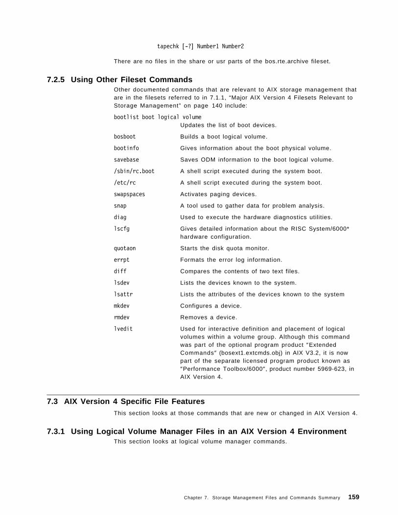
tapechk [-?] Number1 Number2
There are no files in the share or usr parts of the bos.rte.archive fileset.
7.2.5 Using Other Fileset CommandsOther documented commands that are relevant to AIX storage management thatare in the filesets referred to in 7.1.1, “Major AIX Version 4 Filesets Relevant toStorage Management” on page 140 include:
bootlist boot logical volumeUpdates the list of boot devices.
bosboot Builds a boot logical volume.
bootinfo Gives information about the boot physical volume.
savebase Saves ODM information to the boot logical volume.
/sbin/rc.boot A shell script executed during the system boot.
/etc/rc A shell script executed during the system boot.
swapspaces Activates paging devices.
snap A tool used to gather data for problem analysis.
diag Used to execute the hardware diagnostics utilities.
lscfg Gives detailed information about the RISC System/6000*hardware configuration.
quotaon Starts the disk quota monitor.
errpt Formats the error log information.
diff Compares the contents of two text files.
lsdev Lists the devices known to the system.
lsattr Lists the attributes of the devices known to the system
mkdev Configures a device.
rmdev Removes a device.
lvedit Used for interactive definition and placement of logicalvolumes within a volume group. Although this commandwas part of the optional program product ″ExtendedCommands″ (bosext1.extcmds.obj) in AIX V3.2, it is nowpart of the separate licensed program product known as″Performance Toolbox/6000″, product number 5969-623, inAIX Version 4.
7.3 AIX Version 4 Specific File FeaturesThis section looks at those commands that are new or changed in AIX Version 4.
7.3.1 Using Logical Volume Manager Files in an AIX Version 4 EnvironmentThis section looks at logical volume manager commands.
Chapter 7. Storage Management Files and Commands Summary 159
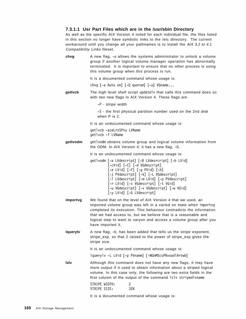
7.3.1.1 Usr Part Files which are in the /usr/sbin DirectoryAs well as the specific AIX Version 4 noted for each individual file, the files listedin this section no longer have symbolic links to the /etc directory. The currentworkaround until you change all your pathnames is to install the AIX 3.2 to 4.1Compatibility Links fileset.
chvg A new flag, -u allows the systems administrator to unlock a volumegroup if another logical volume manager operation has abnormallyterminated. It is important to ensure that no other process is usingthis volume group when this process is run.
It is a documented command whose usage is:
chvg [-a Auto on] [-Q quorum] [-u] VGname...
getlvcb The high level shell script updatelv that calls this command does sowith two new flags in AIX Version 4. These flags are
-P - stripe width
-S - the first physical partition number used on the 2nd diskwhen P is 2.
It is an undocumented command whose usage is:
getlvcb -aceLrsSPtu LVNamegetlvcb -f LVName
getlvodm getlvodm obtains volume group and logical volume information fromthe ODM. In AIX Version 4, it has a new flag, -G.
It is an undocumented command whose usage is:
getlvodm [-a LVdescript] [-B LVdesrcript] [-b LVid][-cVid] [-C] [-d VGdescript][-e LVid] [-F] [-g PVid] [-h][-j PVdescript] [-k] [-L VGdescript][-l LVdescript] [-m LVid] [-p PVdescript][-r LVid] [-s VGdescript] [-t VGid][-u VGdescript] [-v VGdescript] [-w VGid][-y LVid] [-G LVdescript]
importvg We found that on the level of AIX Version 4 that we used, animported volume group was left in a varied on state when importvgcompleted its execution. This behaviour contradicts the informationthat we had access to, but we believe that is a reasonable andlogical step to want to varyon and access a volume group after youhave imported it.
lquerylv A new flag, -b, has been added that tells us the stripe exponent,stripe_exp, so that 2 raised to the power of stripe_exp gives thestripe size.
It is an undocumented command whose usage is:
lquerylv -L LVid [-p PVname] [-NGnMScsPRvoadlArtwb]
lslv Although this command does not have any new flags, it may havemore output if it used to obtain information about a striped logicalvolume. In this case only, the following are two extra fields in thefirst column of the output of the command lslv stripedlvname
STRIPE WIDTH: 2STRIPE SIZE: 32K
It is a documented command whose usage is:
160 AIX Storage Management
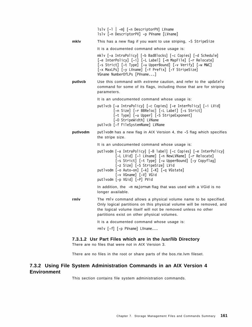
lslv [-l | -m] [-n DescriptorPV] LVnamelslv [-n DescriptorPV] -p PVname [LVname]
mklv This has a new flag if you want to use striping, -S StripeSize
It is a documented command whose usage is:
mklv [-a IntraPolicy] [-b BadBlocks] [-c Copies] [-d Schedule][-e InterPolicy] [-i] [-L Label] [-m MapFile] [-r Relocate][-s Strict] [-t Type] [-u UpperBound] [-v Verify] [-w MWC][-x MaxLPs] [-y LVname] [-Y Prefix] [-Y StripeSize]VGname NumberOfLPs [PVname...]
putlvcb Use this command with extreme caution, and refer to the updatelvcommand for some of its flags, including those that are for stripingparameters.
It is an undocumented command whose usage is:
putlvcb [-a IntraPolicy] [-c Copies] [-e InterPolicy] [-i LVid][-n Size] [-r BBReloc] [-L Label] [-s Strict][-t Type] [-u Upper] [-S StripeExponent][-O StripeWidth] LVName
putlvcb [-f FileSystemName] LVName
putlvodm putlvodm has a new flag in AIX Version 4, the -S flag which specifiesthe stripe size.
It is an undocumented command whose usage is:
putlvodm [-a IntraPolicy] [-B label] [-c Copies] [-e InterPolicy][-L LVid] [-l LVname] [-n NewLVName] [-r Relocate][-s Strict] [-t Type] [-u UpperBound] [-y Copyflag][-z Size] [-S StripeSize] LVid
putlvodm [-o Auto-on] [-k] [-K] [-q VGstate][-v VGname] [-V] VGid
putlvodm [-p VGid] [-P] PVid
In addition, the -m majornum flag that was used with a VGid is nolonger available.
rmlv The rmlv command allows a physical volume name to be specified.Only logical partitions on this physical volume will be removed, andthe logical volume itself will not be removed unless no otherpartitions exist on other physical volumes.
It is a documented command whose usage is:
rmlv [-f] [-p PVname] LVname...
7.3.1.2 Usr Part Files which are in the /usr/lib DirectoryThere are no files that were not in AIX Version 3.
There are no files in the root or share parts of the bos.rte.lvm fileset.
7.3.2 Using File System Administration Commands in an AIX Version 4Environment
This section contains file system administration commands.
Chapter 7. Storage Management Files and Commands Summary 161
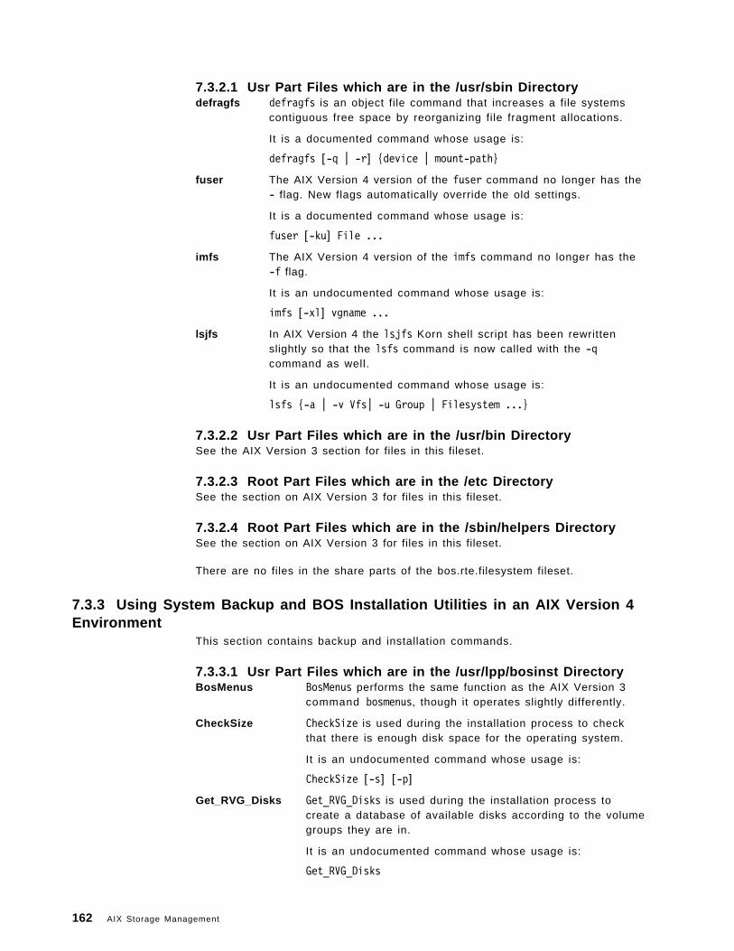
7.3.2.1 Usr Part Files which are in the /usr/sbin Directorydefragfs defragfs is an object file command that increases a file systems
contiguous free space by reorganizing file fragment allocations.
It is a documented command whose usage is:
defragfs [-q | -r] {device | mount-path}
fuser The AIX Version 4 version of the fuser command no longer has the- flag. New flags automatically override the old settings.
It is a documented command whose usage is:
fuser [-ku] File ...
imfs The AIX Version 4 version of the imfs command no longer has the-f flag.
It is an undocumented command whose usage is:
imfs [-xl] vgname ...
lsjfs In AIX Version 4 the lsjfs Korn shell script has been rewrittenslightly so that the lsfs command is now called with the -qcommand as well.
It is an undocumented command whose usage is:
lsfs {-a | -v Vfs| -u Group | Filesystem ...}
7.3.2.2 Usr Part Files which are in the /usr/bin DirectorySee the AIX Version 3 section for files in this fileset.
7.3.2.3 Root Part Files which are in the /etc DirectorySee the section on AIX Version 3 for files in this fileset.
7.3.2.4 Root Part Files which are in the /sbin/helpers DirectorySee the section on AIX Version 3 for files in this fileset.
There are no files in the share parts of the bos.rte.filesystem fileset.
7.3.3 Using System Backup and BOS Installation Utilities in an AIX Version 4Environment
This section contains backup and installation commands.
7.3.3.1 Usr Part Files which are in the /usr/lpp/bosinst DirectoryBosMenus BosMenus performs the same function as the AIX Version 3
command bosmenus, though it operates slightly differently.
CheckSize CheckSize is used during the installation process to checkthat there is enough disk space for the operating system.
It is an undocumented command whose usage is:
CheckSize [-s] [-p]
Get_RVG_Disks Get_RVG_Disks is used during the installation process tocreate a database of available disks according to the volumegroups they are in.
It is an undocumented command whose usage is:
Get_RVG_Disks
162 AIX Storage Management
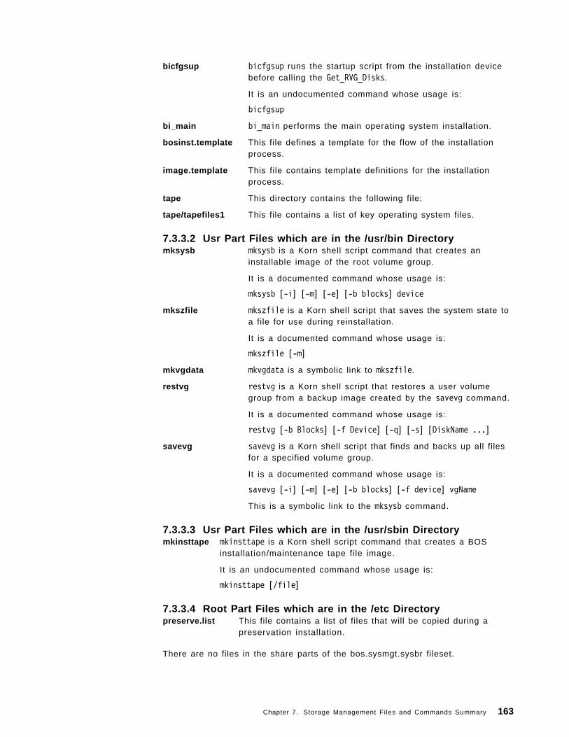
bicfgsup bicfgsup runs the startup script from the installation devicebefore calling the Get_RVG_Disks.
It is an undocumented command whose usage is:
bicfgsup
bi_main bi_main performs the main operating system installation.
bosinst.template This file defines a template for the flow of the installationprocess.
image.template This file contains template definitions for the installationprocess.
tape This directory contains the following file:
tape/tapefiles1 This file contains a list of key operating system files.
7.3.3.2 Usr Part Files which are in the /usr/bin Directorymksysb mksysb is a Korn shell script command that creates an
installable image of the root volume group.
It is a documented command whose usage is:
mksysb [-i] [-m] [-e] [-b blocks] device
mkszfile mkszfile is a Korn shell script that saves the system state toa file for use during reinstallation.
It is a documented command whose usage is:
mkszfile [-m]
mkvgdata mkvgdata is a symbolic link to mkszfile.
restvg restvg is a Korn shell script that restores a user volumegroup from a backup image created by the savevg command.
It is a documented command whose usage is:
restvg [-b Blocks] [-f Device] [-q] [-s] [DiskName ...]
savevg savevg is a Korn shell script that finds and backs up all filesfor a specified volume group.
It is a documented command whose usage is:
savevg [-i] [-m] [-e] [-b blocks] [-f device] vgName
This is a symbolic link to the mksysb command.
7.3.3.3 Usr Part Files which are in the /usr/sbin Directorymkinsttape mkinsttape is a Korn shell script command that creates a BOS
installation/maintenance tape file image.
It is an undocumented command whose usage is:
mkinsttape [/file]
7.3.3.4 Root Part Files which are in the /etc Directorypreserve.list This file contains a list of files that will be copied during a
preservation installation.
There are no files in the share parts of the bos.sysmgt.sysbr fileset.
Chapter 7. Storage Management Files and Commands Summary 163
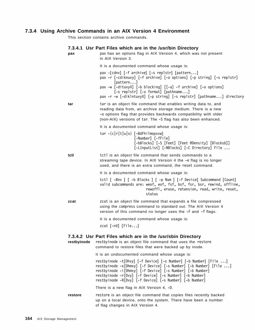
7.3.4 Using Archive Commands in an AIX Version 4 EnvironmentThis section contains archive commands.
7.3.4.1 Usr Part Files which are in the /usr/bin Directorypax pax has an options flag in AIX Version 4, which was not present
in AIX Version 3.
It is a documented command whose usage is:
pax -[cdnv] [-f archive] [-s replstr] [pattern...]pax -r [-cdiknuvy] [-f archive] [-o options] [-p string] [-s replstr]
[pattern...]pax -w [-dituvyX] [-b blocking] [[-a] -f archive] [-o options]
[-s replstr] [-x format] [pathname...]pax -r -w [-diklntuvyX] [-p string] [-s replstr] [pathname...] directory
tar tar is an object file command that enables writing data to, andreading data from, an archive storage medium. There is a new-o options flag that provides backwards compatibility with older(non-AIX) versions of tar. The -S flag has also been enhanced.
It is a documented command whose usage is:
tar -{c|r|t|u|x} [-BdFhilmopsvw][-Number] [-fFile][-bBlocks] [-S [Feet] [Feet @Density] [Blocksb]][-LInputList] [-NBlocks] [-C Directory] File ...
tctl tctl is an object file command that sends commands to astreaming tape device. In AIX Version 4 the -e flag is no longerused, and there is an extra command, the reset command.
It is a documented command whose usage is:
tctl [ -Bnv ] [ -b Blocks ] [ -p Num ] [-f Device] Subcommand [Count]valid subcommands are: weof, eof, fsf, bsf, fsr, bsr, rewind, offline,
rewoffl, erase, retension, read, write, reset,status
zcat zcat is an object file command that expands a file compressedusing the compress command to standard out. The AIX Version 4version of this command no longer uses the -F and -f flags.
It is a documented command whose usage is:
zcat [-nV] [File...]
7.3.4.2 Usr Part Files which are in the /usr/sbin Directoryrestbyinode restbyinode is an object file command that uses the restore
command to restore files that were backed up by inode.
It is an undocumented command whose usage is:
restbyinode -t[Dhvy] [-f Device] [-s Number] [-b Number] [File ...]restbyinode -x[Dhmvy] [-f Device] [-s Number] [-b Number] [File ...]restbyinode -i[Dhmvy] [-f Device] [-s Number] [-b Number]restbyinode -r[Dvy] [-f Device] [-s Number] [-b Number]restbyinode -R[Dvy] [-f Device] [-s Number] [-b Number]
There is a new flag in AIX Version 4, -D.
restore restore is an object file command that copies files recently backedup on a local device, onto the system. There have been a numberof flag changes in AIX Version 4.
164 AIX Storage Management
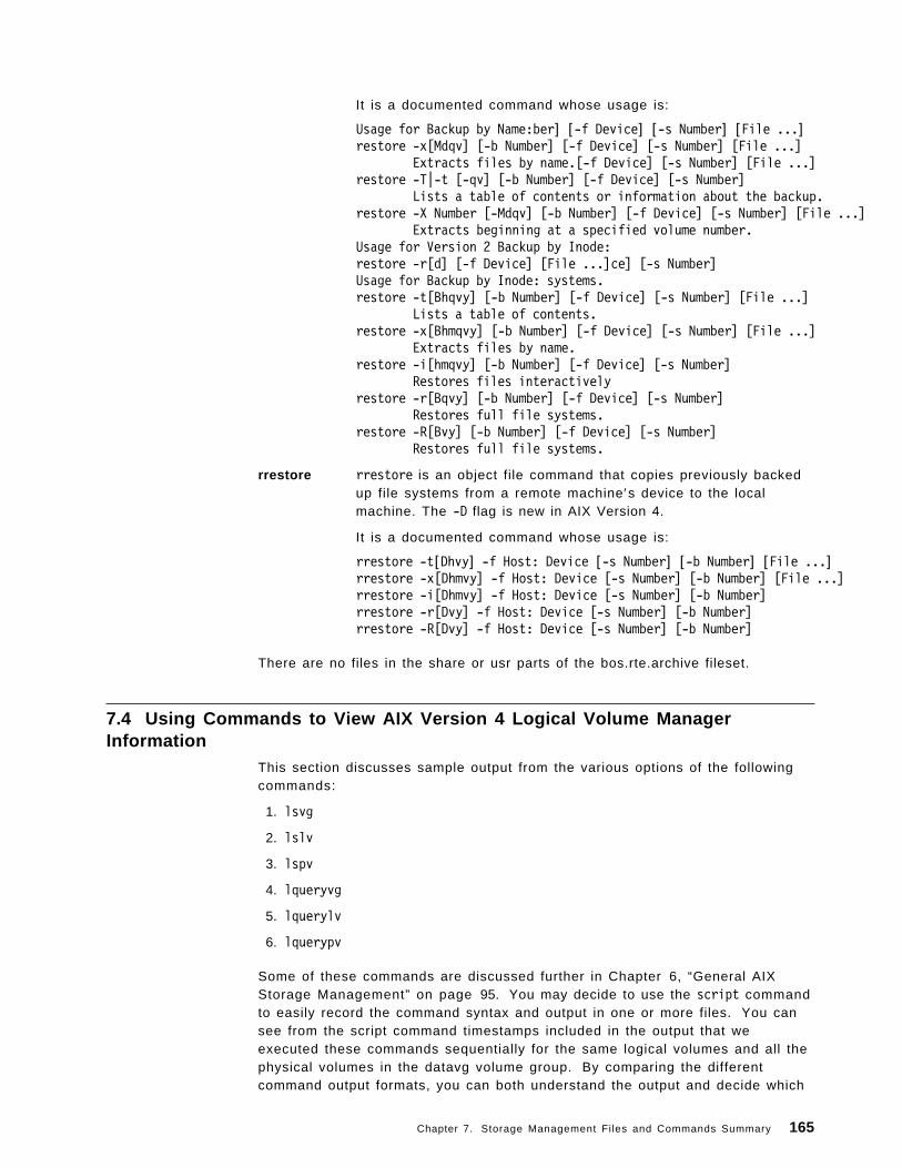
It is a documented command whose usage is:
Usage for Backup by Name:ber] [-f Device] [-s Number] [File ...]restore -x[Mdqv] [-b Number] [-f Device] [-s Number] [File ...]
Extracts files by name.[-f Device] [-s Number] [File ...]restore -T|-t [-qv] [-b Number] [-f Device] [-s Number]
Lists a table of contents or information about the backup.restore -X Number [-Mdqv] [-b Number] [-f Device] [-s Number] [File ...]
Extracts beginning at a specified volume number.Usage for Version 2 Backup by Inode:restore -r[d] [-f Device] [File ...]ce] [-s Number]Usage for Backup by Inode: systems.restore -t[Bhqvy] [-b Number] [-f Device] [-s Number] [File ...]
Lists a table of contents.restore -x[Bhmqvy] [-b Number] [-f Device] [-s Number] [File ...]
Extracts files by name.restore -i[hmqvy] [-b Number] [-f Device] [-s Number]
Restores files interactivelyrestore -r[Bqvy] [-b Number] [-f Device] [-s Number]
Restores full file systems.restore -R[Bvy] [-b Number] [-f Device] [-s Number]
Restores full file systems.
rrestore rrestore is an object file command that copies previously backedup file systems from a remote machine′s device to the localmachine. The -D flag is new in AIX Version 4.
It is a documented command whose usage is:
rrestore -t[Dhvy] -f Host: Device [-s Number] [-b Number] [File ...]rrestore -x[Dhmvy] -f Host: Device [-s Number] [-b Number] [File ...]rrestore -i[Dhmvy] -f Host: Device [-s Number] [-b Number]rrestore -r[Dvy] -f Host: Device [-s Number] [-b Number]rrestore -R[Dvy] -f Host: Device [-s Number] [-b Number]
There are no files in the share or usr parts of the bos.rte.archive fileset.
7.4 Using Commands to View AIX Version 4 Logical Volume ManagerInformation
This section discusses sample output from the various options of the followingcommands:
1. lsvg
2. lslv
3. lspv
4. lqueryvg
5. lquerylv
6. lquerypv
Some of these commands are discussed further in Chapter 6, “General AIXStorage Management” on page 95. You may decide to use the script commandto easily record the command syntax and output in one or more files. You cansee from the script command timestamps included in the output that weexecuted these commands sequentially for the same logical volumes and all thephysical volumes in the datavg volume group. By comparing the differentcommand output formats, you can both understand the output and decide which
Chapter 7. Storage Management Files and Commands Summary 165
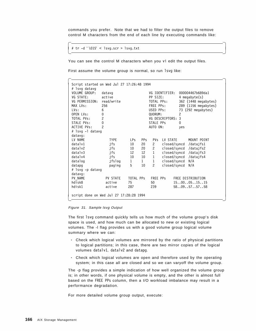
commands you prefer. Note that we had to filter the output files to removecontrol M characters from the end of each line by executing commands like:
� �# tr -d ′ \015′ < lsvg.scr > lsvg.txt� �
You can see the control M characters when you vi edit the output files.
First assume the volume group is normal, so run lsvg like:
� �Script started on Wed Jul 27 17:26:48 1994# lsvg datavgVOLUME GROUP: datavg VG IDENTIFIER: 000004467b689da1VG STATE: active PP SIZE: 4 megabyte(s)VG PERMISSION: read/write TOTAL PPs: 362 (1448 megabytes)MAX LVs: 256 FREE PPs: 289 (1156 megabytes)LVs: 6 USED PPs: 73 (292 megabytes)OPEN LVs: 0 QUORUM: 2TOTAL PVs: 2 VG DESCRIPTORS: 3STALE PVs: 0 STALE PPs 0ACTIVE PVs: 2 AUTO ON: yes# lsvg -l datavgdatavg:LV NAME TYPE LPs PPs PVs LV STATE MOUNT POINTdatalv1 jfs 10 20 2 closed/syncd /datajfs1datalv2 jfs 10 20 2 closed/syncd /datajfs2datalv3 jfs 12 12 1 closed/syncd /datajfs3datalv4 jfs 10 10 1 closed/syncd /datajfs4datalog jfslog 1 1 1 closed/syncd N/Adatapg paging 5 10 2 closed/syncd N/A# lsvg -p datavgdatavg:PV_NAME PV STATE TOTAL PPs FREE PPs FREE DISTRIBUTIONhdisk8 active 75 50 15..00..05..15..15hdisk1 active 287 239 58..09..57..57..58
script done on Wed Jul 27 17:28:28 1994� �Figure 31. Sample lsvg Output
The first lsvg command quickly tells us how much of the volume group′s diskspace is used, and how much can be allocated to new or existing logicalvolumes. The -l flag provides us with a good volume group logical volumesummary where we can:
• Check which logical volumes are mirrored by the ratio of physical partitionsto logical partitions; in this case, there are two mirror copies of the logicalvolumes datalv1, datalv2 and datapg.
• Check which logical volumes are open and therefore used by the operatingsystem; in this case all are closed and so we can varyoff the volume group.
The -p flag provides a simple indication of how well organized the volume groupis; in other words, if one physical volume is empty, and the other is almost fullbased on the FREE PPs column, then a I/O workload imbalance may result in aperformance degradation.
For more detailed volume group output, execute:
166 AIX Storage Management
� �Script started on Wed Jul 27 17:28:37 1994# lsvg -M datavg
datavghdisk8:1-15hdisk8:16 datalv1:1:1hdisk8:17 datalv1:2:1hdisk8:18 datalv1:3:1hdisk8:19 datalv1:4:1hdisk8:20 datalv1:5:1hdisk8:21 datalv1:6:1hdisk8:22 datalv1:7:1hdisk8:23 datalv1:8:1hdisk8:24 datalv1:9:1hdisk8:25 datalv1:10:1hdisk8:26 datalv2:1:2hdisk8:27 datalv2:2:2hdisk8:28 datalv2:3:2hdisk8:29 datalv2:4:2hdisk8:30 datalv2:5:2hdisk8:31 datalv2:6:2hdisk8:32 datalv2:7:2hdisk8:33 datalv2:8:2hdisk8:34 datalv2:9:2hdisk8:35 datalv2:10:2hdisk8:36 datapg:1:2hdisk8:37 datapg:2:2hdisk8:38 datapg:3:2hdisk8:39 datapg:4:2hdisk8:40 datapg:5:2hdisk8:41-75hdisk1:1-58hdisk1:59 datalv1:1:2hdisk1:60 datalv1:2:2hdisk1:61 datalv1:3:2hdisk1:62 datalv1:4:2hdisk1:63 datalv1:5:2hdisk1:64 datalv1:6:2hdisk1:65 datalv1:7:2hdisk1:66 datalv1:8:2hdisk1:67 datalv1:9:2hdisk1:68 datalv1:10:2� �
Figure 32. Sample lsvg -M Output
and continuing on the next screen:
Chapter 7. Storage Management Files and Commands Summary 167
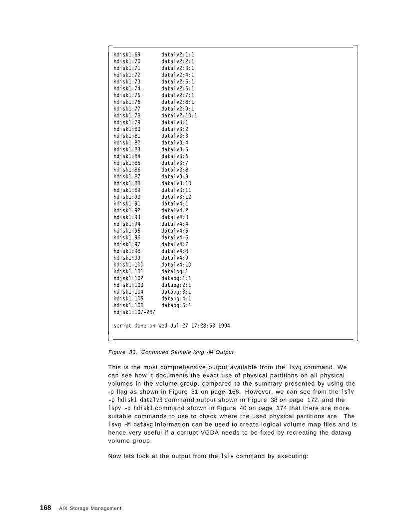
� �hdisk1:69 datalv2:1:1hdisk1:70 datalv2:2:1hdisk1:71 datalv2:3:1hdisk1:72 datalv2:4:1hdisk1:73 datalv2:5:1hdisk1:74 datalv2:6:1hdisk1:75 datalv2:7:1hdisk1:76 datalv2:8:1hdisk1:77 datalv2:9:1hdisk1:78 datalv2:10:1hdisk1:79 datalv3:1hdisk1:80 datalv3:2hdisk1:81 datalv3:3hdisk1:82 datalv3:4hdisk1:83 datalv3:5hdisk1:84 datalv3:6hdisk1:85 datalv3:7hdisk1:86 datalv3:8hdisk1:87 datalv3:9hdisk1:88 datalv3:10hdisk1:89 datalv3:11hdisk1:90 datalv3:12hdisk1:91 datalv4:1hdisk1:92 datalv4:2hdisk1:93 datalv4:3hdisk1:94 datalv4:4hdisk1:95 datalv4:5hdisk1:96 datalv4:6hdisk1:97 datalv4:7hdisk1:98 datalv4:8hdisk1:99 datalv4:9hdisk1:100 datalv4:10hdisk1:101 datalog:1hdisk1:102 datapg:1:1hdisk1:103 datapg:2:1hdisk1:104 datapg:3:1hdisk1:105 datapg:4:1hdisk1:106 datapg:5:1hdisk1:107-287
script done on Wed Jul 27 17:28:53 1994
� �Figure 33. Continued Sample lsvg -M Output
This is the most comprehensive output available from the lsvg command. Wecan see how it documents the exact use of physical partitions on all physicalvolumes in the volume group, compared to the summary presented by using the-p flag as shown in Figure 31 on page 166. However, we can see from the lslv-p hdisk1 datalv3 command output shown in Figure 38 on page 172. and thelspv -p hdisk1 command shown in Figure 40 on page 174 that there are moresuitable commands to use to check where the used physical partitions are. Thelsvg -M datavg information can be used to create logical volume map files and ishence very useful if a corrupt VGDA needs to be fixed by recreating the datavgvolume group.
Now lets look at the output from the lslv command by executing:
168 AIX Storage Management
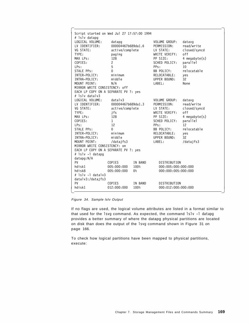
� �Script started on Wed Jul 27 17:57:00 1994# lslv datapgLOGICAL VOLUME: datapg VOLUME GROUP: datavgLV IDENTIFIER: 000004467b689da1.6 PERMISSION: read/writeVG STATE: active/complete LV STATE: closed/syncdTYPE: paging WRITE VERIFY: offMAX LPs: 128 PP SIZE: 4 megabyte(s)COPIES: 2 SCHED POLICY: parallelLPs: 5 PPs: 10STALE PPs: 0 BB POLICY: relocatableINTER-POLICY: minimum RELOCATABLE: yesINTRA-POLICY: middle UPPER BOUND: 32MOUNT POINT: N/A LABEL: NoneMIRROR WRITE CONSISTENCY: offEACH LP COPY ON A SEPARATE PV ?: yes# lslv datalv3LOGICAL VOLUME: datalv3 VOLUME GROUP: datavgLV IDENTIFIER: 000004467b689da1.3 PERMISSION: read/writeVG STATE: active/complete LV STATE: closed/syncdTYPE: jfs WRITE VERIFY: offMAX LPs: 128 PP SIZE: 4 megabyte(s)COPIES: 1 SCHED POLICY: parallelLPs: 12 PPs: 12STALE PPs: 0 BB POLICY: relocatableINTER-POLICY: minimum RELOCATABLE: yesINTRA-POLICY: middle UPPER BOUND: 32MOUNT POINT: /datajfs3 LABEL: /datajfs3MIRROR WRITE CONSISTENCY: onEACH LP COPY ON A SEPARATE PV ?: yes# lslv -l datapgdatapg:N/APV COPIES IN BAND DISTRIBUTIONhdisk1 005:000:000 100% 000:005:000:000:000hdisk8 005:000:000 0% 000:000:005:000:000# lslv -l datalv3datalv3:/datajfs3PV COPIES IN BAND DISTRIBUTIONhdisk1 012:000:000 100% 000:012:000:000:000� �
Figure 34. Sample lslv Output
If no flags are used, the logical volume attributes are listed in a format similar tothat used for the lsvg command. As expected, the command lslv -l datapgprovides a better summary of where the datapg physical partitions are locatedon disk than does the output of the lsvg command shown in Figure 31 onpage 166.
To check how logical partitions have been mapped to physical partitions,execute:
Chapter 7. Storage Management Files and Commands Summary 169
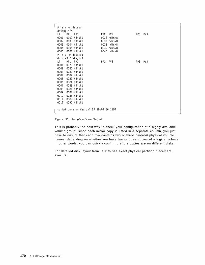
� �# lslv -m datapgdatapg:N/ALP PP1 PV1 PP2 PV2 PP3 PV30001 0102 hdisk1 0036 hdisk80002 0103 hdisk1 0037 hdisk80003 0104 hdisk1 0038 hdisk80004 0105 hdisk1 0039 hdisk80005 0106 hdisk1 0040 hdisk8# lslv -m datalv3datalv3:/datajfs3LP PP1 PV1 PP2 PV2 PP3 PV30001 0079 hdisk10002 0080 hdisk10003 0081 hdisk10004 0082 hdisk10005 0083 hdisk10006 0084 hdisk10007 0085 hdisk10008 0086 hdisk10009 0087 hdisk10010 0088 hdisk10011 0089 hdisk10012 0090 hdisk1
script done on Wed Jul 27 18:04:36 1994� �Figure 35. Sample lslv -m Output
This is probably the best way to check your configuration of a highly availablevolume group. Since each mirror copy is listed in a separate column, you justhave to ensure that each row contains two or three different physical volumenames, depending on whether you have two or three copies of a logical volume.In other words, you can quickly confirm that the copies are on different disks.
For detailed disk layout from lslv to see exact physical partition placement,execute:
170 AIX Storage Management
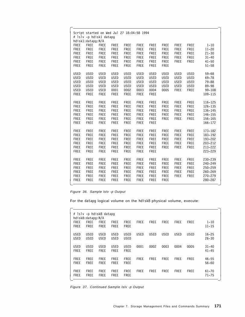
� �Script started on Wed Jul 27 18:04:58 1994# lslv -p hdisk1 datapghdisk1:datapg:N/AFREE FREE FREE FREE FREE FREE FREE FREE FREE FREE 1-10FREE FREE FREE FREE FREE FREE FREE FREE FREE FREE 11-20FREE FREE FREE FREE FREE FREE FREE FREE FREE FREE 21-30FREE FREE FREE FREE FREE FREE FREE FREE FREE FREE 31-40FREE FREE FREE FREE FREE FREE FREE FREE FREE FREE 41-50FREE FREE FREE FREE FREE FREE FREE FREE 51-58
USED USED USED USED USED USED USED USED USED USED 59-68USED USED USED USED USED USED USED USED USED USED 69-78USED USED USED USED USED USED USED USED USED USED 79-88USED USED USED USED USED USED USED USED USED USED 89-98USED USED USED 0001 0002 0003 0004 0005 FREE FREE 99-108FREE FREE FREE FREE FREE FREE FREE 109-115
FREE FREE FREE FREE FREE FREE FREE FREE FREE FREE 116-125FREE FREE FREE FREE FREE FREE FREE FREE FREE FREE 126-135FREE FREE FREE FREE FREE FREE FREE FREE FREE FREE 136-145FREE FREE FREE FREE FREE FREE FREE FREE FREE FREE 146-155FREE FREE FREE FREE FREE FREE FREE FREE FREE FREE 156-165FREE FREE FREE FREE FREE FREE FREE 166-172
FREE FREE FREE FREE FREE FREE FREE FREE FREE FREE 173-182FREE FREE FREE FREE FREE FREE FREE FREE FREE FREE 183-192FREE FREE FREE FREE FREE FREE FREE FREE FREE FREE 193-202FREE FREE FREE FREE FREE FREE FREE FREE FREE FREE 203-212FREE FREE FREE FREE FREE FREE FREE FREE FREE FREE 213-222FREE FREE FREE FREE FREE FREE FREE 223-229
FREE FREE FREE FREE FREE FREE FREE FREE FREE FREE 230-239FREE FREE FREE FREE FREE FREE FREE FREE FREE FREE 240-249FREE FREE FREE FREE FREE FREE FREE FREE FREE FREE 250-259FREE FREE FREE FREE FREE FREE FREE FREE FREE FREE 260-269FREE FREE FREE FREE FREE FREE FREE FREE FREE FREE 270-279FREE FREE FREE FREE FREE FREE FREE FREE 280-287� �
Figure 36. Sample lslv -p Output
For the datapg logical volume on the hdisk8 physical volume, execute:
� �# lslv -p hdisk8 datapghdisk8:datapg:N/AFREE FREE FREE FREE FREE FREE FREE FREE FREE FREE 1-10FREE FREE FREE FREE FREE 11-15
USED USED USED USED USED USED USED USED USED USED 16-25USED USED USED USED USED 26-30
USED USED USED USED USED 0001 0002 0003 0004 0005 31-40FREE FREE FREE FREE FREE 41-45
FREE FREE FREE FREE FREE FREE FREE FREE FREE FREE 46-55FREE FREE FREE FREE FREE 56-60
FREE FREE FREE FREE FREE FREE FREE FREE FREE FREE 61-70FREE FREE FREE FREE FREE 71-75� �
Figure 37. Continued Sample lslv -p Output
Chapter 7. Storage Management Files and Commands Summary 171
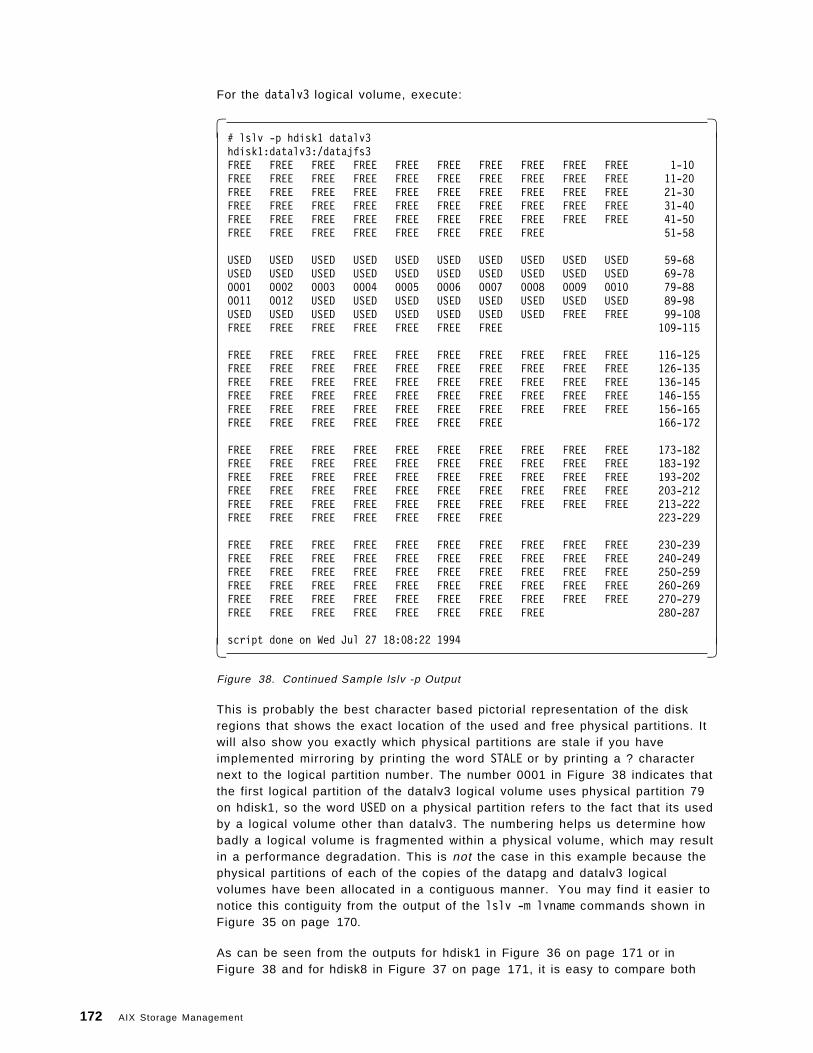
For the datalv3 logical volume, execute:
� �# lslv -p hdisk1 datalv3hdisk1:datalv3:/datajfs3FREE FREE FREE FREE FREE FREE FREE FREE FREE FREE 1-10FREE FREE FREE FREE FREE FREE FREE FREE FREE FREE 11-20FREE FREE FREE FREE FREE FREE FREE FREE FREE FREE 21-30FREE FREE FREE FREE FREE FREE FREE FREE FREE FREE 31-40FREE FREE FREE FREE FREE FREE FREE FREE FREE FREE 41-50FREE FREE FREE FREE FREE FREE FREE FREE 51-58
USED USED USED USED USED USED USED USED USED USED 59-68USED USED USED USED USED USED USED USED USED USED 69-780001 0002 0003 0004 0005 0006 0007 0008 0009 0010 79-880011 0012 USED USED USED USED USED USED USED USED 89-98USED USED USED USED USED USED USED USED FREE FREE 99-108FREE FREE FREE FREE FREE FREE FREE 109-115
FREE FREE FREE FREE FREE FREE FREE FREE FREE FREE 116-125FREE FREE FREE FREE FREE FREE FREE FREE FREE FREE 126-135FREE FREE FREE FREE FREE FREE FREE FREE FREE FREE 136-145FREE FREE FREE FREE FREE FREE FREE FREE FREE FREE 146-155FREE FREE FREE FREE FREE FREE FREE FREE FREE FREE 156-165FREE FREE FREE FREE FREE FREE FREE 166-172
FREE FREE FREE FREE FREE FREE FREE FREE FREE FREE 173-182FREE FREE FREE FREE FREE FREE FREE FREE FREE FREE 183-192FREE FREE FREE FREE FREE FREE FREE FREE FREE FREE 193-202FREE FREE FREE FREE FREE FREE FREE FREE FREE FREE 203-212FREE FREE FREE FREE FREE FREE FREE FREE FREE FREE 213-222FREE FREE FREE FREE FREE FREE FREE 223-229
FREE FREE FREE FREE FREE FREE FREE FREE FREE FREE 230-239FREE FREE FREE FREE FREE FREE FREE FREE FREE FREE 240-249FREE FREE FREE FREE FREE FREE FREE FREE FREE FREE 250-259FREE FREE FREE FREE FREE FREE FREE FREE FREE FREE 260-269FREE FREE FREE FREE FREE FREE FREE FREE FREE FREE 270-279FREE FREE FREE FREE FREE FREE FREE FREE 280-287
script done on Wed Jul 27 18:08:22 1994� �Figure 38. Continued Sample lslv -p Output
This is probably the best character based pictorial representation of the diskregions that shows the exact location of the used and free physical partitions. Itwill also show you exactly which physical partitions are stale if you haveimplemented mirroring by printing the word STALE or by printing a ? characternext to the logical partition number. The number 0001 in Figure 38 indicates thatthe first logical partition of the datalv3 logical volume uses physical partition 79on hdisk1, so the word USED on a physical partition refers to the fact that its usedby a logical volume other than datalv3. The numbering helps us determine howbadly a logical volume is fragmented within a physical volume, which may resultin a performance degradation. This is not the case in this example because thephysical partitions of each of the copies of the datapg and datalv3 logicalvolumes have been allocated in a contiguous manner. You may find it easier tonotice this contiguity from the output of the lslv -m lvname commands shown inFigure 35 on page 170.
As can be seen from the outputs for hdisk1 in Figure 36 on page 171 or inFigure 38 and for hdisk8 in Figure 37 on page 171, it is easy to compare both
172 AIX Storage Management
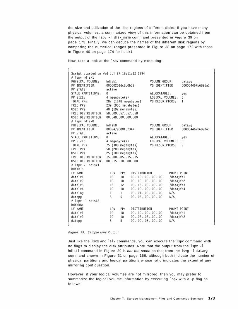
the size and utilization of the disk regions of different disks. If you have manyphysical volumes, a summarized view of this information can be obtained fromthe output of the lspv -l disk_name command presented in Figure 39 onpage 173. Finally, we can deduce the names of the different disk regions bycomparing the numerical ranges presented in Figure 38 on page 172 with thosein Figure 40 on page 174 for hdisk1.
Now, take a look at the lspv command by executing:
� �Script started on Wed Jul 27 18:11:12 1994# lspv hdisk1PHYSICAL VOLUME: hdisk1 VOLUME GROUP: datavgPV IDENTIFIER: 00000201dc8b0b32 VG IDENTIFIER 000004467b689da1PV STATE: activeSTALE PARTITIONS: 0 ALLOCATABLE: yesPP SIZE: 4 megabyte(s) LOGICAL VOLUMES: 6TOTAL PPs: 287 (1148 megabytes) VG DESCRIPTORS: 1FREE PPs: 239 (956 megabytes)USED PPs: 48 (192 megabytes)FREE DISTRIBUTION: 58..09..57..57..58USED DISTRIBUTION: 00..48..00..00..00# lspv hdisk8PHYSICAL VOLUME: hdisk8 VOLUME GROUP: datavgPV IDENTIFIER: 0002479088f5f347 VG IDENTIFIER 000004467b689da1PV STATE: activeSTALE PARTITIONS: 0 ALLOCATABLE: yesPP SIZE: 4 megabyte(s) LOGICAL VOLUMES: 3TOTAL PPs: 75 (300 megabytes) VG DESCRIPTORS: 2FREE PPs: 50 (200 megabytes)USED PPs: 25 (100 megabytes)FREE DISTRIBUTION: 15..00..05..15..15USED DISTRIBUTION: 00..15..10..00..00# lspv -l hdisk1hdisk1:LV NAME LPs PPs DISTRIBUTION MOUNT POINTdatalv1 10 10 00..10..00..00..00 /datajfs1datalv2 10 10 00..10..00..00..00 /datajfs2datalv3 12 12 00..12..00..00..00 /datajfs3datalv4 10 10 00..10..00..00..00 /datajfs4datalog 1 1 00..01..00..00..00 N/Adatapg 5 5 00..05..00..00..00 N/A# lspv -l hdisk8hdisk8:LV NAME LPs PPs DISTRIBUTION MOUNT POINTdatalv1 10 10 00..10..00..00..00 /datajfs1datalv2 10 10 00..05..05..00..00 /datajfs2datapg 5 5 00..00..05..00..00 N/A� �
Figure 39. Sample lspv Output
Just like the lsvg and lslv commands, you can execute the lspv command withno flags to display the disk attributes. Note that the output from the lspv -lhdisk1 command in Figure 39 is not the same as that from the lsvg -l datavgcommand shown in Figure 31 on page 166, although both indicate the number ofphysical partitions and logical partitions whose ratio indicates the extent of anymirroring configuration.
However, if your logical volumes are not mirrored, then you may prefer tosummarize the logical volume information by executing lspv with a -p flag asfollows:
Chapter 7. Storage Management Files and Commands Summary 173
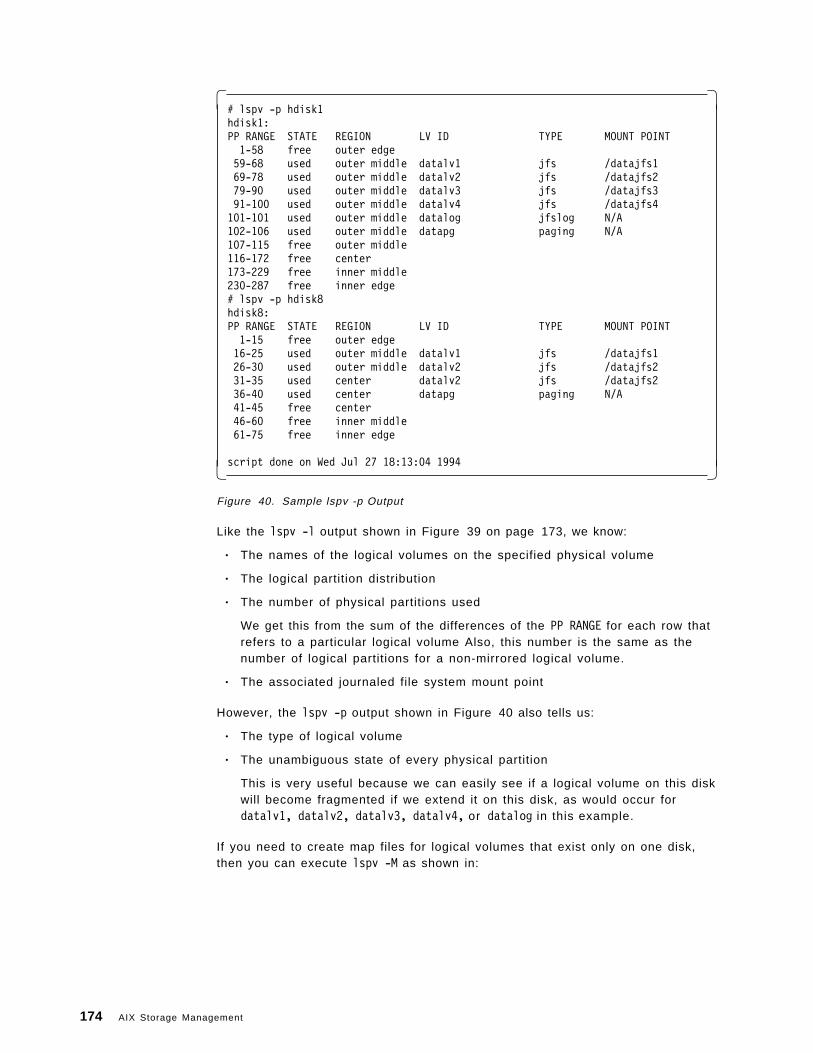
� �# lspv -p hdisk1hdisk1:PP RANGE STATE REGION LV ID TYPE MOUNT POINT1-58 free outer edge59-68 used outer middle datalv1 jfs /datajfs169-78 used outer middle datalv2 jfs /datajfs279-90 used outer middle datalv3 jfs /datajfs391-100 used outer middle datalv4 jfs /datajfs4101-101 used outer middle datalog jfslog N/A102-106 used outer middle datapg paging N/A107-115 free outer middle116-172 free center173-229 free inner middle230-287 free inner edge# lspv -p hdisk8hdisk8:PP RANGE STATE REGION LV ID TYPE MOUNT POINT1-15 free outer edge16-25 used outer middle datalv1 jfs /datajfs126-30 used outer middle datalv2 jfs /datajfs231-35 used center datalv2 jfs /datajfs236-40 used center datapg paging N/A41-45 free center46-60 free inner middle61-75 free inner edge
script done on Wed Jul 27 18:13:04 1994� �Figure 40. Sample lspv -p Output
Like the lspv -l output shown in Figure 39 on page 173, we know:
• The names of the logical volumes on the specified physical volume
• The logical partition distribution
• The number of physical partitions used
We get this from the sum of the differences of the PP RANGE for each row thatrefers to a particular logical volume Also, this number is the same as thenumber of logical partitions for a non-mirrored logical volume.
• The associated journaled file system mount point
However, the lspv -p output shown in Figure 40 also tells us:
• The type of logical volume
• The unambiguous state of every physical partition
This is very useful because we can easily see if a logical volume on this diskwill become fragmented if we extend it on this disk, as would occur fordatalv1, datalv2, datalv3, datalv4, or datalog in this example.
If you need to create map files for logical volumes that exist only on one disk,then you can execute lspv -M as shown in:
174 AIX Storage Management
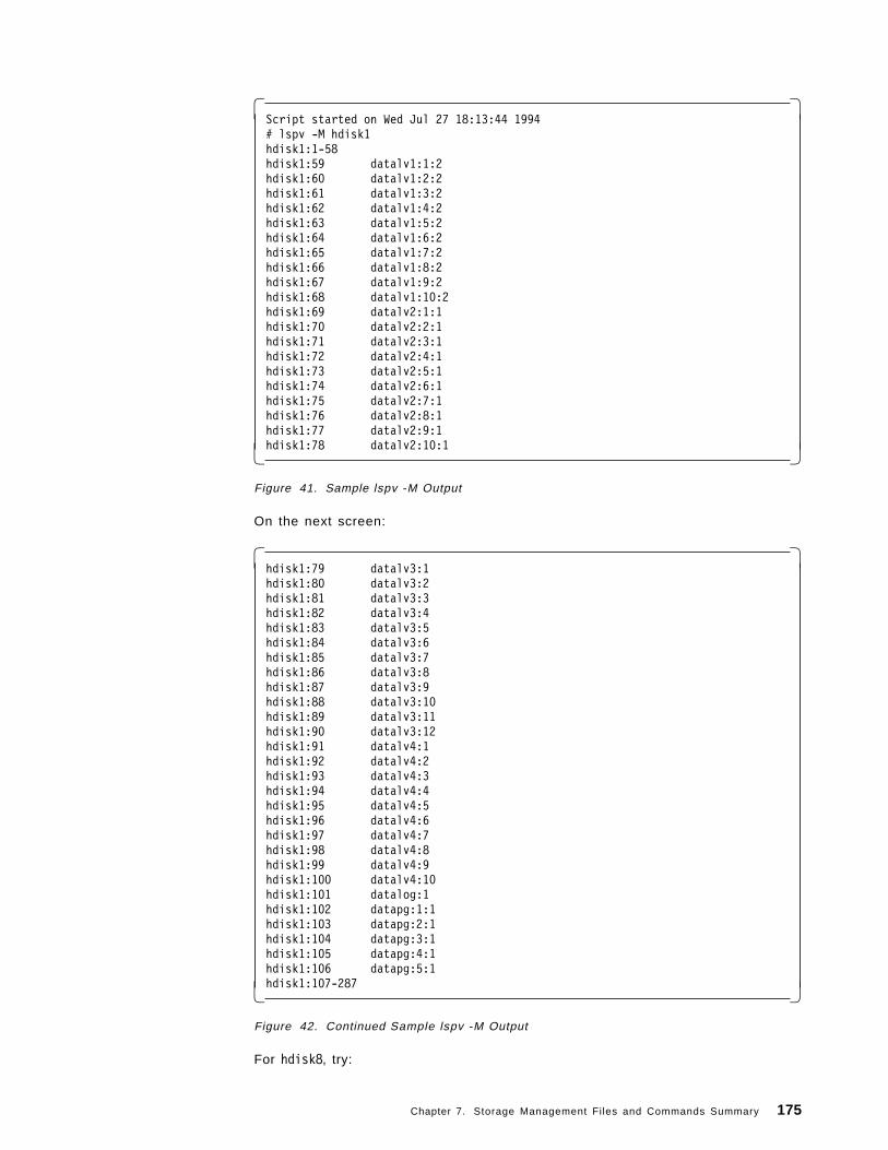
� �Script started on Wed Jul 27 18:13:44 1994# lspv -M hdisk1hdisk1:1-58hdisk1:59 datalv1:1:2hdisk1:60 datalv1:2:2hdisk1:61 datalv1:3:2hdisk1:62 datalv1:4:2hdisk1:63 datalv1:5:2hdisk1:64 datalv1:6:2hdisk1:65 datalv1:7:2hdisk1:66 datalv1:8:2hdisk1:67 datalv1:9:2hdisk1:68 datalv1:10:2hdisk1:69 datalv2:1:1hdisk1:70 datalv2:2:1hdisk1:71 datalv2:3:1hdisk1:72 datalv2:4:1hdisk1:73 datalv2:5:1hdisk1:74 datalv2:6:1hdisk1:75 datalv2:7:1hdisk1:76 datalv2:8:1hdisk1:77 datalv2:9:1hdisk1:78 datalv2:10:1� �
Figure 41. Sample lspv -M Output
On the next screen:
� �hdisk1:79 datalv3:1hdisk1:80 datalv3:2hdisk1:81 datalv3:3hdisk1:82 datalv3:4hdisk1:83 datalv3:5hdisk1:84 datalv3:6hdisk1:85 datalv3:7hdisk1:86 datalv3:8hdisk1:87 datalv3:9hdisk1:88 datalv3:10hdisk1:89 datalv3:11hdisk1:90 datalv3:12hdisk1:91 datalv4:1hdisk1:92 datalv4:2hdisk1:93 datalv4:3hdisk1:94 datalv4:4hdisk1:95 datalv4:5hdisk1:96 datalv4:6hdisk1:97 datalv4:7hdisk1:98 datalv4:8hdisk1:99 datalv4:9hdisk1:100 datalv4:10hdisk1:101 datalog:1hdisk1:102 datapg:1:1hdisk1:103 datapg:2:1hdisk1:104 datapg:3:1hdisk1:105 datapg:4:1hdisk1:106 datapg:5:1hdisk1:107-287� �
Figure 42. Continued Sample lspv -M Output
For hdisk8, try:
Chapter 7. Storage Management Files and Commands Summary 175
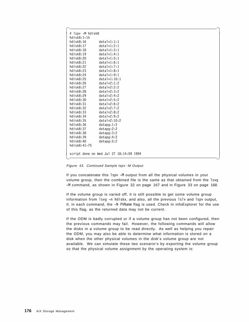
� �# lspv -M hdisk8hdisk8:1-15hdisk8:16 datalv1:1:1hdisk8:17 datalv1:2:1hdisk8:18 datalv1:3:1hdisk8:19 datalv1:4:1hdisk8:20 datalv1:5:1hdisk8:21 datalv1:6:1hdisk8:22 datalv1:7:1hdisk8:23 datalv1:8:1hdisk8:24 datalv1:9:1hdisk8:25 datalv1:10:1hdisk8:26 datalv2:1:2hdisk8:27 datalv2:2:2hdisk8:28 datalv2:3:2hdisk8:29 datalv2:4:2hdisk8:30 datalv2:5:2hdisk8:31 datalv2:6:2hdisk8:32 datalv2:7:2hdisk8:33 datalv2:8:2hdisk8:34 datalv2:9:2hdisk8:35 datalv2:10:2hdisk8:36 datapg:1:2hdisk8:37 datapg:2:2hdisk8:38 datapg:3:2hdisk8:39 datapg:4:2hdisk8:40 datapg:5:2hdisk8:41-75
script done on Wed Jul 27 18:14:09 1994� �Figure 43. Continued Sample lspv -M Output
If you concatenate this lspv -M output from all the physical volumes in yourvolume group, then the combined file is the same as that obtained from the lsvg-M command, as shown in Figure 32 on page 167 and in Figure 33 on page 168.
If the volume group is varied off, it is still possible to get some volume groupinformation from lsvg -n hdiskx, and also, all the previous lslv and lspv output,if, in each command, the -N PVName flag is used. Check in infoExplorer for the useof this flag, as the returned data may not be current.
If the ODM is badly corrupted or if a volume group has not been configured, thenthe previous commands may fail. However, the following commands will allowthe disks in a volume group to be read directly. As well as helping you repairthe ODM, you may also be able to determine what information is stored on adisk when the other physical volumes in the disk′s volume group are notavailable. We can simulate these two scenario′s by exporting the volume groupso that the physical volume assignment by the operating system is:
176 AIX Storage Management
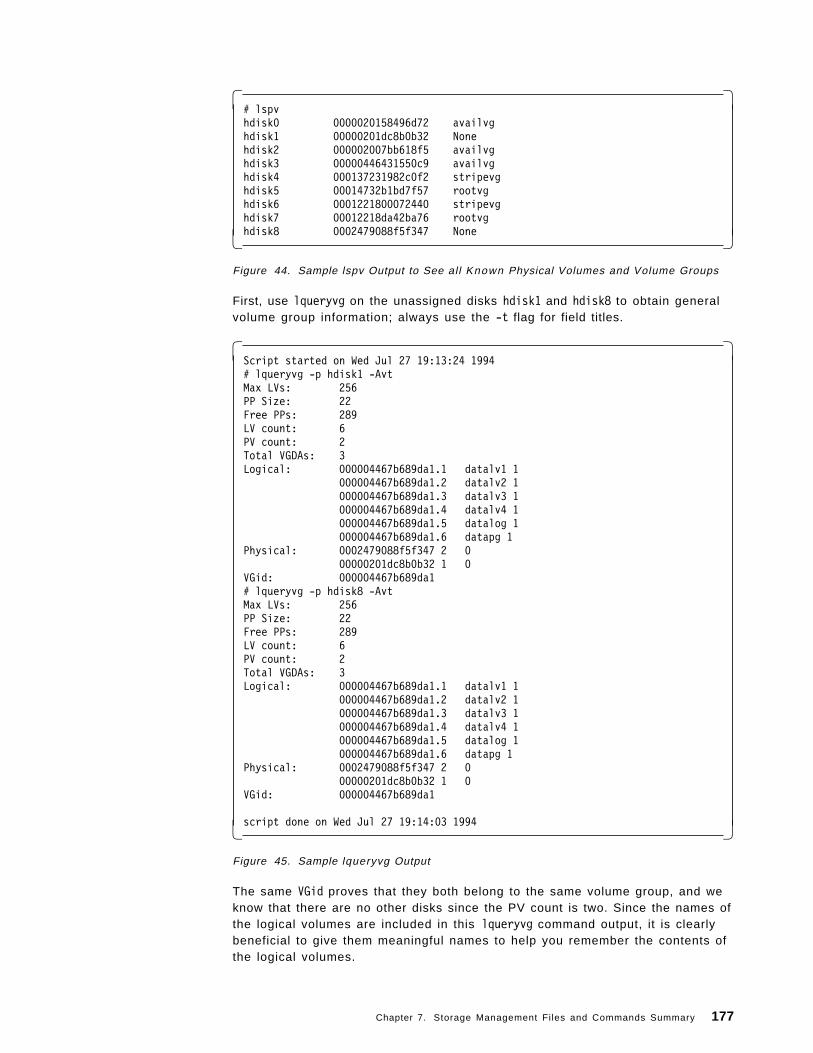
� �# lspvhdisk0 0000020158496d72 availvghdisk1 00000201dc8b0b32 Nonehdisk2 000002007bb618f5 availvghdisk3 00000446431550c9 availvghdisk4 000137231982c0f2 stripevghdisk5 00014732b1bd7f57 rootvghdisk6 0001221800072440 stripevghdisk7 00012218da42ba76 rootvghdisk8 0002479088f5f347 None� �
Figure 44. Sample lspv Output to See all Known Physical Volumes and Volume Groups
First, use lqueryvg on the unassigned disks hdisk1 and hdisk8 to obtain generalvolume group information; always use the -t flag for field titles.
� �Script started on Wed Jul 27 19:13:24 1994# lqueryvg -p hdisk1 -AvtMax LVs: 256PP Size: 22Free PPs: 289LV count: 6PV count: 2Total VGDAs: 3Logical: 000004467b689da1.1 datalv1 1
000004467b689da1.2 datalv2 1000004467b689da1.3 datalv3 1000004467b689da1.4 datalv4 1000004467b689da1.5 datalog 1000004467b689da1.6 datapg 1
Physical: 0002479088f5f347 2 000000201dc8b0b32 1 0
VGid: 000004467b689da1# lqueryvg -p hdisk8 -AvtMax LVs: 256PP Size: 22Free PPs: 289LV count: 6PV count: 2Total VGDAs: 3Logical: 000004467b689da1.1 datalv1 1
000004467b689da1.2 datalv2 1000004467b689da1.3 datalv3 1000004467b689da1.4 datalv4 1000004467b689da1.5 datalog 1000004467b689da1.6 datapg 1
Physical: 0002479088f5f347 2 000000201dc8b0b32 1 0
VGid: 000004467b689da1
script done on Wed Jul 27 19:14:03 1994� �Figure 45. Sample lqueryvg Output
The same VGid proves that they both belong to the same volume group, and weknow that there are no other disks since the PV count is two. Since the names ofthe logical volumes are included in this lqueryvg command output, it is clearlybeneficial to give them meaningful names to help you remember the contents ofthe logical volumes.
Chapter 7. Storage Management Files and Commands Summary 177
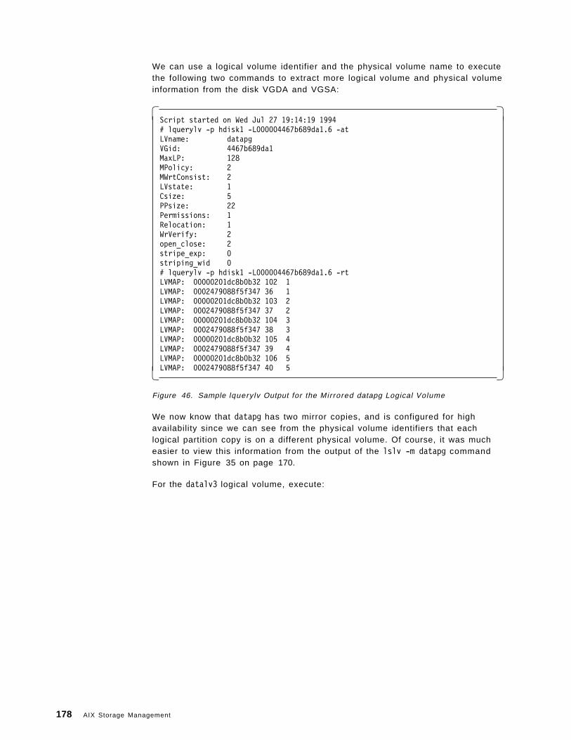
We can use a logical volume identifier and the physical volume name to executethe following two commands to extract more logical volume and physical volumeinformation from the disk VGDA and VGSA:
� �Script started on Wed Jul 27 19:14:19 1994# lquerylv -p hdisk1 -L000004467b689da1.6 -atLVname: datapgVGid: 4467b689da1MaxLP: 128MPolicy: 2MWrtConsist: 2LVstate: 1Csize: 5PPsize: 22Permissions: 1Relocation: 1WrVerify: 2open_close: 2stripe_exp: 0striping_wid 0# lquerylv -p hdisk1 -L000004467b689da1.6 -rtLVMAP: 00000201dc8b0b32 102 1LVMAP: 0002479088f5f347 36 1LVMAP: 00000201dc8b0b32 103 2LVMAP: 0002479088f5f347 37 2LVMAP: 00000201dc8b0b32 104 3LVMAP: 0002479088f5f347 38 3LVMAP: 00000201dc8b0b32 105 4LVMAP: 0002479088f5f347 39 4LVMAP: 00000201dc8b0b32 106 5LVMAP: 0002479088f5f347 40 5� �
Figure 46. Sample lquerylv Output for the Mirrored datapg Logical Volume
We now know that datapg has two mirror copies, and is configured for highavailability since we can see from the physical volume identifiers that eachlogical partition copy is on a different physical volume. Of course, it was mucheasier to view this information from the output of the lslv -m datapg commandshown in Figure 35 on page 170.
For the datalv3 logical volume, execute:
178 AIX Storage Management
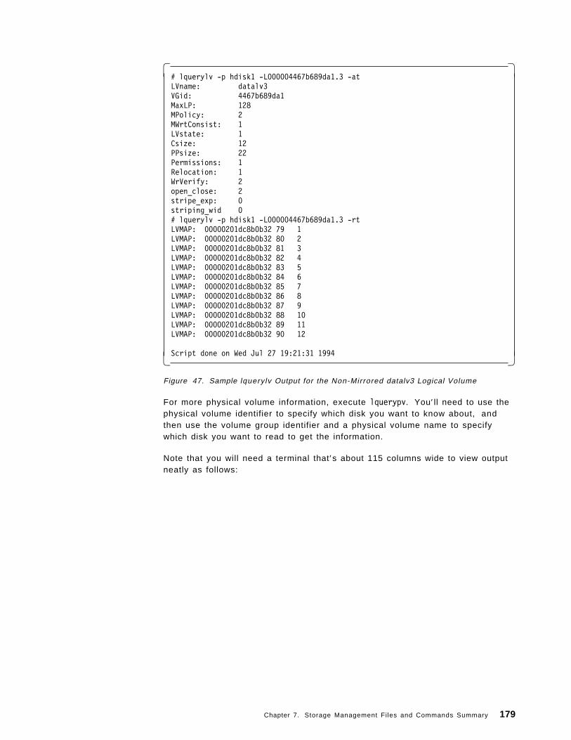
� �# lquerylv -p hdisk1 -L000004467b689da1.3 -atLVname: datalv3VGid: 4467b689da1MaxLP: 128MPolicy: 2MWrtConsist: 1LVstate: 1Csize: 12PPsize: 22Permissions: 1Relocation: 1WrVerify: 2open_close: 2stripe_exp: 0striping_wid 0# lquerylv -p hdisk1 -L000004467b689da1.3 -rtLVMAP: 00000201dc8b0b32 79 1LVMAP: 00000201dc8b0b32 80 2LVMAP: 00000201dc8b0b32 81 3LVMAP: 00000201dc8b0b32 82 4LVMAP: 00000201dc8b0b32 83 5LVMAP: 00000201dc8b0b32 84 6LVMAP: 00000201dc8b0b32 85 7LVMAP: 00000201dc8b0b32 86 8LVMAP: 00000201dc8b0b32 87 9LVMAP: 00000201dc8b0b32 88 10LVMAP: 00000201dc8b0b32 89 11LVMAP: 00000201dc8b0b32 90 12
Script done on Wed Jul 27 19:21:31 1994� �Figure 47. Sample lquerylv Output for the Non-Mirrored datalv3 Logical Volume
For more physical volume information, execute lquerypv. You′ ll need to use thephysical volume identifier to specify which disk you want to know about, andthen use the volume group identifier and a physical volume name to specifywhich disk you want to read to get the information.
Note that you will need a terminal that′s about 115 columns wide to view outputneatly as follows:
Chapter 7. Storage Management Files and Commands Summary 179
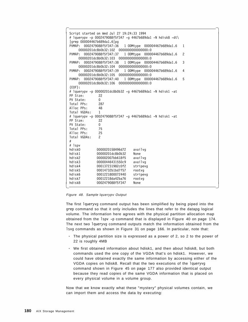
� �Script started on Wed Jul 27 19:24:33 1994# lquerypv -p 0002479088f5f347 -g 4467b689da1 -N hdisk8 -dt\|grep 000004467b689da1.6|pgPVMAP: 0002479088f5f347:36 1 ODMtype 000004467b689da1.6 1
00000201dc8b0b32:102 0000000000000000:0PVMAP: 0002479088f5f347:37 1 ODMtype 000004467b689da1.6 2
00000201dc8b0b32:103 0000000000000000:0PVMAP: 0002479088f5f347:38 1 ODMtype 000004467b689da1.6 3
00000201dc8b0b32:104 0000000000000000:0PVMAP: 0002479088f5f347:39 1 ODMtype 000004467b689da1.6 4
00000201dc8b0b32:105 0000000000000000:0PVMAP: 0002479088f5f347:40 1 ODMtype 000004467b689da1.6 5
00000201dc8b0b32:106 0000000000000000:0(EOF):# lquerypv -p 00000201dc8b0b32 -g 4467b689da1 -N hdisk1 -atPP Size: 22PV State: 0Total PPs: 287Alloc PPs: 48Total VGDAs: 1# lquerypv -p 0002479088f5f347 -g 4467b689da1 -N hdisk1 -atPP Size: 22PV State: 0Total PPs: 75Alloc PPs: 25Total VGDAs: 2## lspvhdisk0 0000020158496d72 availvghdisk1 00000201dc8b0b32 Nonehdisk2 000002007bb618f5 availvghdisk3 00000446431550c9 availvghdisk4 000137231982c0f2 stripevghdisk5 00014732b1bd7f57 rootvghdisk6 0001221800072440 stripevghdisk7 00012218da42ba76 rootvghdisk8 0002479088f5f347 None� �
Figure 48. Sample lquerypv Output
The first lqueryvg command output has been simplified by being piped into thegrep command so that it only includes the lines that refer to the datapg logicalvolume. The information here agrees with the physical partition allocation mapobtained from the lspv -p command that is displayed in Figure 40 on page 174.The next two lqueryvg command outputs match the information obtained from thelsvg commands as shown in Figure 31 on page 166. In particular, note that:
• The physical partition size is expressed as a power of 2, so 2 to the power of22 is roughly 4MB
• We first obtained information about hdisk1, and then about hdisk8, but bothcommands used the one copy of the VGDA that′s on hdisk1. However, wecould have obtained exactly the same information by accessing either of theVGDA copies on hdisk8. Recall that the two executions of the lqueryvgcommand shown in Figure 45 on page 177 also provided identical outputbecause they read copies of the same VGDA information that is placed onevery physical volume in a volume group.
Now that we know exactly what these ″mystery″ physical volumes contain, wecan import them and access the data by executing:
180 AIX Storage Management
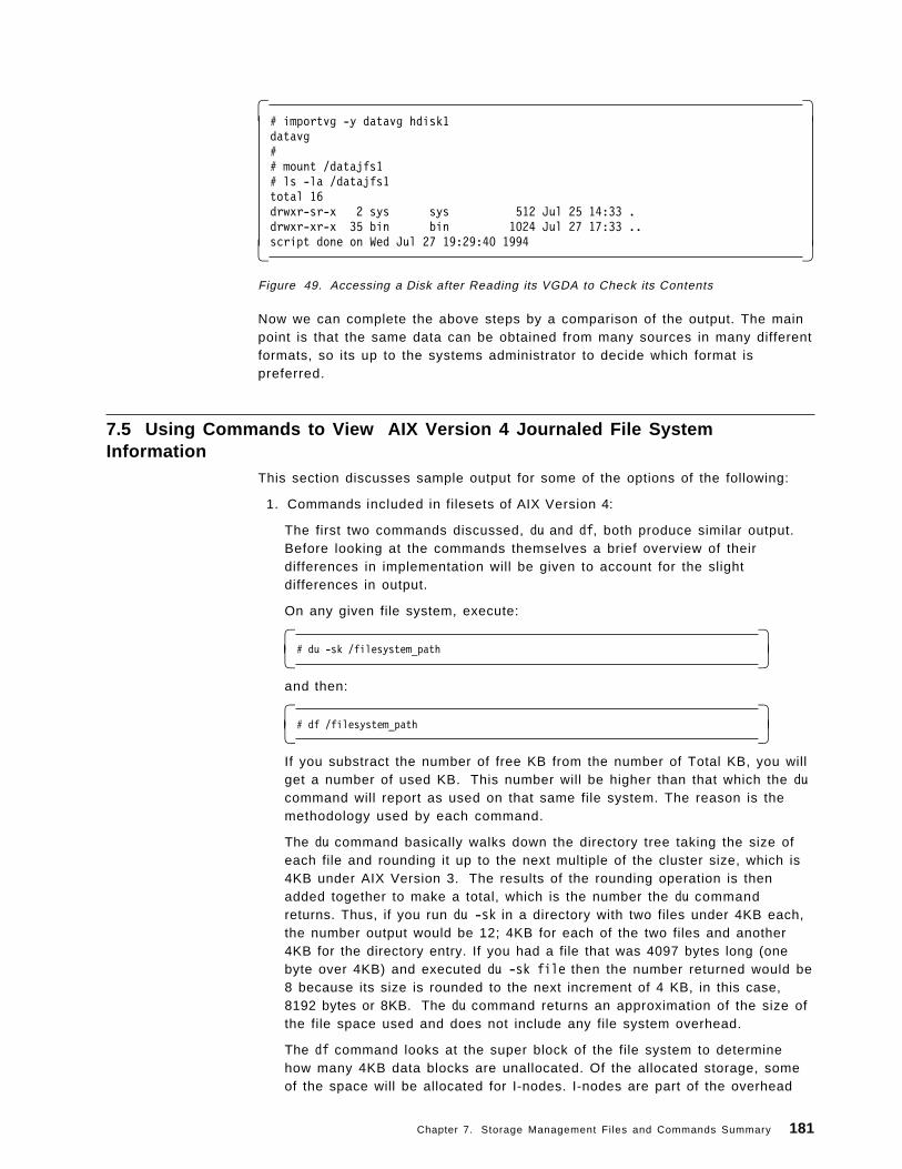
� �# importvg -y datavg hdisk1datavg## mount /datajfs1# ls -la /datajfs1total 16drwxr-sr-x 2 sys sys 512 Jul 25 14:33 .drwxr-xr-x 35 bin bin 1024 Jul 27 17:33 ..script done on Wed Jul 27 19:29:40 1994� �
Figure 49. Accessing a Disk after Reading its VGDA to Check its Contents
Now we can complete the above steps by a comparison of the output. The mainpoint is that the same data can be obtained from many sources in many differentformats, so its up to the systems administrator to decide which format ispreferred.
7.5 Using Commands to View AIX Version 4 Journaled File SystemInformation
This section discusses sample output for some of the options of the following:
1. Commands included in filesets of AIX Version 4:
The first two commands discussed, du and df, both produce similar output.Before looking at the commands themselves a brief overview of theirdifferences in implementation will be given to account for the slightdifferences in output.
On any given file system, execute:
� �# du -sk /filesystem_path� �
and then:
� �# df /filesystem_path� �
If you substract the number of free KB from the number of Total KB, you willget a number of used KB. This number will be higher than that which the ducommand will report as used on that same file system. The reason is themethodology used by each command.
The du command basically walks down the directory tree taking the size ofeach file and rounding it up to the next multiple of the cluster size, which is4KB under AIX Version 3. The results of the rounding operation is thenadded together to make a total, which is the number the du commandreturns. Thus, if you run du -sk in a directory with two files under 4KB each,the number output would be 12; 4KB for each of the two files and another4KB for the directory entry. If you had a file that was 4097 bytes long (onebyte over 4KB) and executed du -sk file then the number returned would be8 because its size is rounded to the next increment of 4 KB, in this case,8192 bytes or 8KB. The du command returns an approximation of the size ofthe file space used and does not include any file system overhead.
The df command looks at the super block of the file system to determinehow many 4KB data blocks are unallocated. Of the allocated storage, someof the space will be allocated for I-nodes. I-nodes are part of the overhead
Chapter 7. Storage Management Files and Commands Summary 181
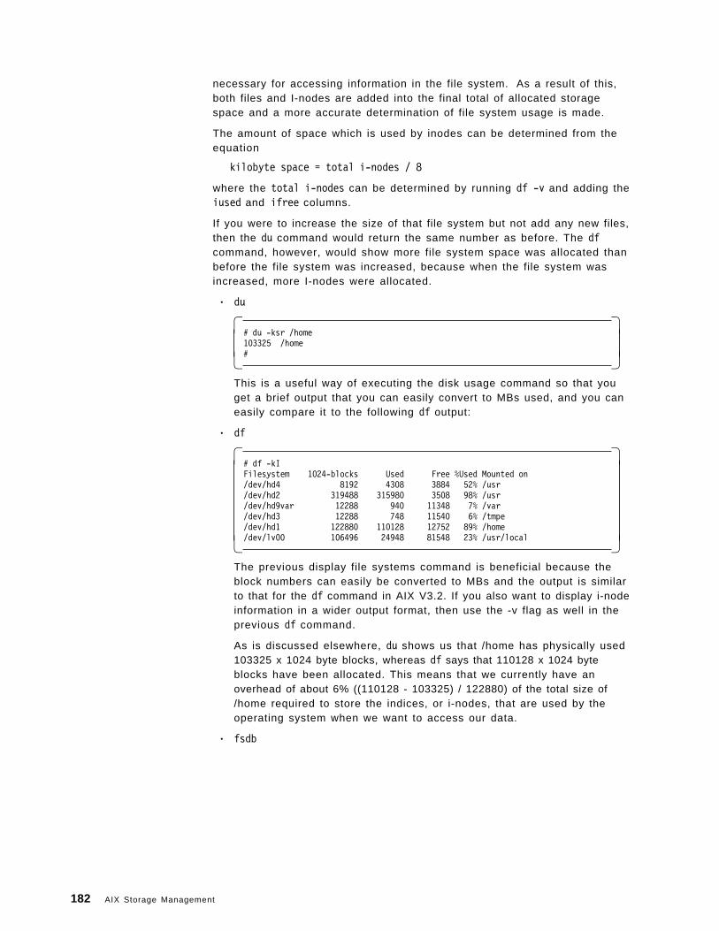
necessary for accessing information in the file system. As a result of this,both files and I-nodes are added into the final total of allocated storagespace and a more accurate determination of file system usage is made.
The amount of space which is used by inodes can be determined from theequation
kilobyte space = total i-nodes / 8
where the total i-nodes can be determined by running df -v and adding theiused and ifree columns.
If you were to increase the size of that file system but not add any new files,then the du command would return the same number as before. The dfcommand, however, would show more file system space was allocated thanbefore the file system was increased, because when the file system wasincreased, more I-nodes were allocated.
• du
� �# du -ksr /home103325 /home#� �
This is a useful way of executing the disk usage command so that youget a brief output that you can easily convert to MBs used, and you caneasily compare it to the following df output:
• df
� �# df -kIFilesystem 1024-blocks Used Free %Used Mounted on/dev/hd4 8192 4308 3884 52% /usr/dev/hd2 319488 315980 3508 98% /usr/dev/hd9var 12288 940 11348 7% /var/dev/hd3 12288 748 11540 6% /tmpe/dev/hd1 122880 110128 12752 89% /home/dev/lv00 106496 24948 81548 23% /usr/local� �
The previous display file systems command is beneficial because theblock numbers can easily be converted to MBs and the output is similarto that for the df command in AIX V3.2. If you also want to display i-nodeinformation in a wider output format, then use the -v flag as well in theprevious df command.
As is discussed elsewhere, du shows us that /home has physically used103325 x 1024 byte blocks, whereas df says that 110128 x 1024 byteblocks have been allocated. This means that we currently have anoverhead of about 6% ((110128 - 103325) / 122880) of the total size of/home required to store the indices, or i-nodes, that are used by theoperating system when we want to access our data.
• fsdb
182 AIX Storage Management
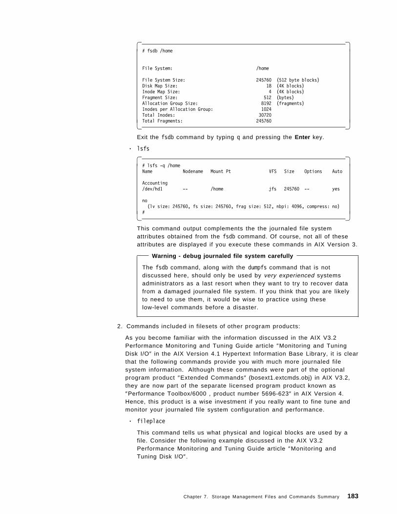
� �# fsdb /home
File System: /home
File System Size: 245760 (512 byte blocks)Disk Map Size: 18 (4K blocks)Inode Map Size: 4 (4K blocks)Fragment Size: 512 (bytes)Allocation Group Size: 8192 (fragments)Inodes per Allocation Group: 1024Total Inodes: 30720Total Fragments: 245760� �
Exit the fsdb command by typing q and pressing the Enter key.
• lsfs
� �# lsfs -q /homeName Nodename Mount Pt VFS Size Options Auto
Accounting/dev/hd1 -- /home jfs 245760 -- yes
no(lv size: 245760, fs size: 245760, frag size: 512, nbpi: 4096, compress: no)
#� �This command output complements the the journaled file systemattributes obtained from the fsdb command. Of course, not all of theseattributes are displayed if you execute these commands in AIX Version 3.
Warning - debug journaled file system carefully
The fsdb command, along with the dumpfs command that is notdiscussed here, should only be used by very experienced systemsadministrators as a last resort when they want to try to recover datafrom a damaged journaled file system. If you think that you are likelyto need to use them, it would be wise to practice using theselow-level commands before a disaster.
2. Commands included in filesets of other program products:
As you become familiar with the information discussed in the AIX V3.2Performance Monitoring and Tuning Guide article ″Monitoring and TuningDisk I/O″ in the AIX Version 4.1 Hypertext Information Base Library, it is clearthat the following commands provide you with much more journaled filesystem information. Although these commands were part of the optionalprogram product ″Extended Commands″ (bosext1.extcmds.obj) in AIX V3.2,they are now part of the separate licensed program product known as″Performance Toolbox/6000 , product number 5696-623″ in AIX Version 4.Hence, this product is a wise investment if you really want to fine tune andmonitor your journaled file system configuration and performance.
• fileplace
This command tells us what physical and logical blocks are used by afile. Consider the following example discussed in the AIX V3.2Performance Monitoring and Tuning Guide article ″Monitoring andTuning Disk I/O″.
Chapter 7. Storage Management Files and Commands Summary 183
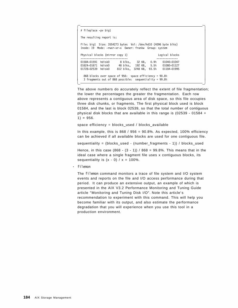
� �# fileplace -pv big1
The resulting report is:
File: big1 Size: 3554273 bytes Vol: /dev/hd10 (4096 byte blks)Inode: 19 Mode: -rwxr-xr-x Owner: frankw Group: system
Physical blocks (mirror copy 1) Logical blocks------------------------------- --------------01584-01591 hdisk0 8 blks, 32 KB, 0.9% 01040-0104701624-01671 hdisk0 48 blks, 192 KB, 5.5% 01080-0112701728-02539 hdisk0 812 blks, 3248 KB, 93.5% 01184-01995
868 blocks over space of 956: space efficiency = 90.8%3 fragments out of 868 possible: sequentiality = 99.8%� �
The above numbers do accurately reflect the extent of file fragmentation;the lower the percentages the greater the fragmentation. Each rowabove represents a contiguous area of disk space, so this file occupiesthree disk chunks, or fragments. The first physical block used is block01584, and the last is block 02539, so that the total number of contiguousphysical disk blocks that are available in this range is (02539 - 01584 +1) = 956.
space efficiency = blocks_used / blocks_available
In this example, this is 868 / 956 = 90.8%. As expected, 100% efficiencycan be achieved if all available blocks are used for one contiguous file.
sequentiality = (blocks_used - (number_fragments - 1)) / blocks_used
Hence, in this case (868 - (3 - 1)) / 868 = 99.8%. This means that in theideal case where a single fragment file uses x contiguous blocks, itssequentiality is (x - 0) / x = 100%.
• filemon
The filemon command monitors a trace of file system and I/O systemevents and reports on the file and I/O access performance during thatperiod. It can produce an extensive output, an example of which ispresented in the AIX V3.2 Performance Monitoring and Tuning Guidearticle ″Monitoring and Tuning Disk I/O″. Note this article′srecommendation to experiment with this command. This will help youbecome familiar with its output, and also estimate the performancedegradation that you will experience when you use this tool in aproduction environment.
184 AIX Storage Management
Chapter 8. Practical Examples
This chapter contains a series of practical examples covering a variety ofstorage management and problem solving situations.
Each example has three major sections:
• An introduction and general description.
• A summary of the commands that can be used by an experienced systemsadministrator.
• A detailed description that may include:
− What the output is and what it means.
− Why a particular command is used.
− How to use the commands, usually with ASCII smit screens, note that onyour screen, the output may vary due to:
- A different level of AIX Version 4.
- Different terminal attributes such as the number of lines displayed inan output screen.
Warning - read smit documentation
Before using smit:
• Become familiar with relevant smit documentation, such asthat provided in AIX Version 4.1 System Management Guide:Operating System and Devices.
• Be aware that some of the storage management menus havebeen changed.
8.1 PlanningBefore a key is pressed to configure the available equipment, careful planning isa wise investment. Hence, we begin by considering what volume group(s) ourdisks should belong to, and how should they be connected to the RISCSystem/6000.
We have nine SCSI-1 disks available that range in capacity from 355MB to 1.2GB.To show a number of different logical volume manager features coexisting in AIXVersion 4, these disks can be initially arranged in four volume groups. Theimplementation of this volume group setup is shown and discussed in 8.3,“Storage Subsystem Design” on page 203.
Since there are two SCSI-1 adapters available for the nine available SCSI-1disks, then four disks can be connected to one adapter, and five disks can beconnected to the second adapter. The CD-ROM and 8mm tape drive are notlikely to be involved in as much I/O as the disks, so their location is not ascritical.
A typical setup of this hardware can be seen from the output of the followinglsdev command:
Copyright IBM Corp. 1994 185
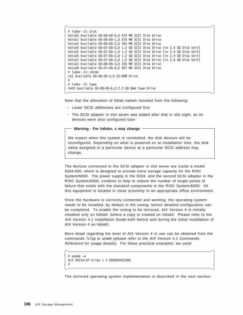
� �# lsdev -Cc diskhdisk0 Available 00-08-00-0,0 670 MB SCSI Disk Drivehdisk1 Available 00-08-00-1,0 670 MB SCSI Disk Drivehdisk2 Available 00-08-00-2,0 355 MB SCSI Disk Drivehdisk4 Available 00-07-00-0,0 1.2 GB SCSI Disk Drive (in 2.4 GB Disk Unit)hdisk5 Available 00-07-00-1,0 1.2 GB SCSI Disk Drive (in 2.4 GB Disk Unit)hdisk6 Available 00-07-00-2,0 1.2 GB SCSI Disk Drive (in 2.4 GB Disk Unit)hdisk7 Available 00-07-00-3,0 1.2 GB SCSI Disk Drive (in 2.4 GB Disk Unit)hdisk3 Available 00-08-00-3,0 320 MB SCSI Disk Drivehdisk8 Available 00-07-00-4,0 857 MB SCSI Disk Drive# lsdev -Cc cdromcd1 Available 00-08-00-4,0 CD-ROM Drive## lsdev -Cc tapermt0 Available 00-08-00-6,0 2.3 GB 8mm Tape Drive� �
Note that the allocation of hdisk names resulted from the following:
• Lower SCSI addresses are configured first
• The SCSI adapter in slot seven was added after that in slot eight, so itsdevices were also configured later
Warning - For hdiskx, x may change
We expect when this system is reinstalled, the disk devices will bereconfigured. Depending on what is powered on at installation time, the diskname assigned to a particular device at a particular SCSI address maychange.
The devices connected to the SCSI adapter in slot seven are inside a model9334-500, which is designed to provide extra storage capacity for the RISCSystem/6000. The power supply in the 9334, and the second SCSI adapter in theRISC System/6000, combine to help to reduce the number of single points offailure that exists with the standard components in the RISC System/6000. Allthis equipment is located in close proximity in an appropriate office environment.
Once the hardware is correctly connected and working, the operating systemneeds to be installed, by default in the rootvg, before detailed configuration canbe completed. To enable the rootvg to be mirrored, AIX Version 4 is initiallyinstalled only on hdisk0, before a copy is created on hdisk2. Please refer to theAIX Version 4.1 Installation Guide both before and during the initial installation ofAIX Version 4 on hdisk0.
More detail regarding the level of AIX Version 4 in use can be obtained from thecommands lslpp or uname (please refer to the AIX Version 4.1 CommandsReference for usage details). For these practical examples, we used:
� �# uname -aAIX 9421A-UP bilbo 1 4 000004461000#� �
The mirrored operating system implementation is described in the next section.
186 AIX Storage Management
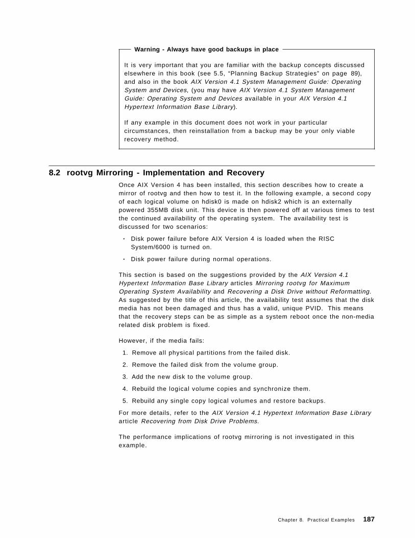
Warning - Always have good backups in place
It is very important that you are familiar with the backup concepts discussedelsewhere in this book (see 5.5, “Planning Backup Strategies” on page 89),and also in the book AIX Version 4.1 System Management Guide: OperatingSystem and Devices, (you may have AIX Version 4.1 System ManagementGuide: Operating System and Devices available in your AIX Version 4.1Hypertext Information Base Library).
If any example in this document does not work in your particularcircumstances, then reinstallation from a backup may be your only viablerecovery method.
8.2 rootvg Mirroring - Implementation and RecoveryOnce AIX Version 4 has been installed, this section describes how to create amirror of rootvg and then how to test it. In the following example, a second copyof each logical volume on hdisk0 is made on hdisk2 which is an externallypowered 355MB disk unit. This device is then powered off at various times to testthe continued availability of the operating system. The availability test isdiscussed for two scenarios:
• Disk power failure before AIX Version 4 is loaded when the RISCSystem/6000 is turned on.
• Disk power failure during normal operations.
This section is based on the suggestions provided by the AIX Version 4.1Hypertext Information Base Library articles Mirroring rootvg for MaximumOperating System Availability and Recovering a Disk Drive without Reformatting.As suggested by the title of this article, the availability test assumes that the diskmedia has not been damaged and thus has a valid, unique PVID. This meansthat the recovery steps can be as simple as a system reboot once the non-mediarelated disk problem is fixed.
However, if the media fails:
1. Remove all physical partit ions from the failed disk.
2. Remove the failed disk from the volume group.
3. Add the new disk to the volume group.
4. Rebuild the logical volume copies and synchronize them.
5. Rebuild any single copy logical volumes and restore backups.
For more details, refer to the AIX Version 4.1 Hypertext Information Base Libraryarticle Recovering from Disk Drive Problems.
The performance implications of rootvg mirroring is not investigated in thisexample.
Chapter 8. Practical Examples 187
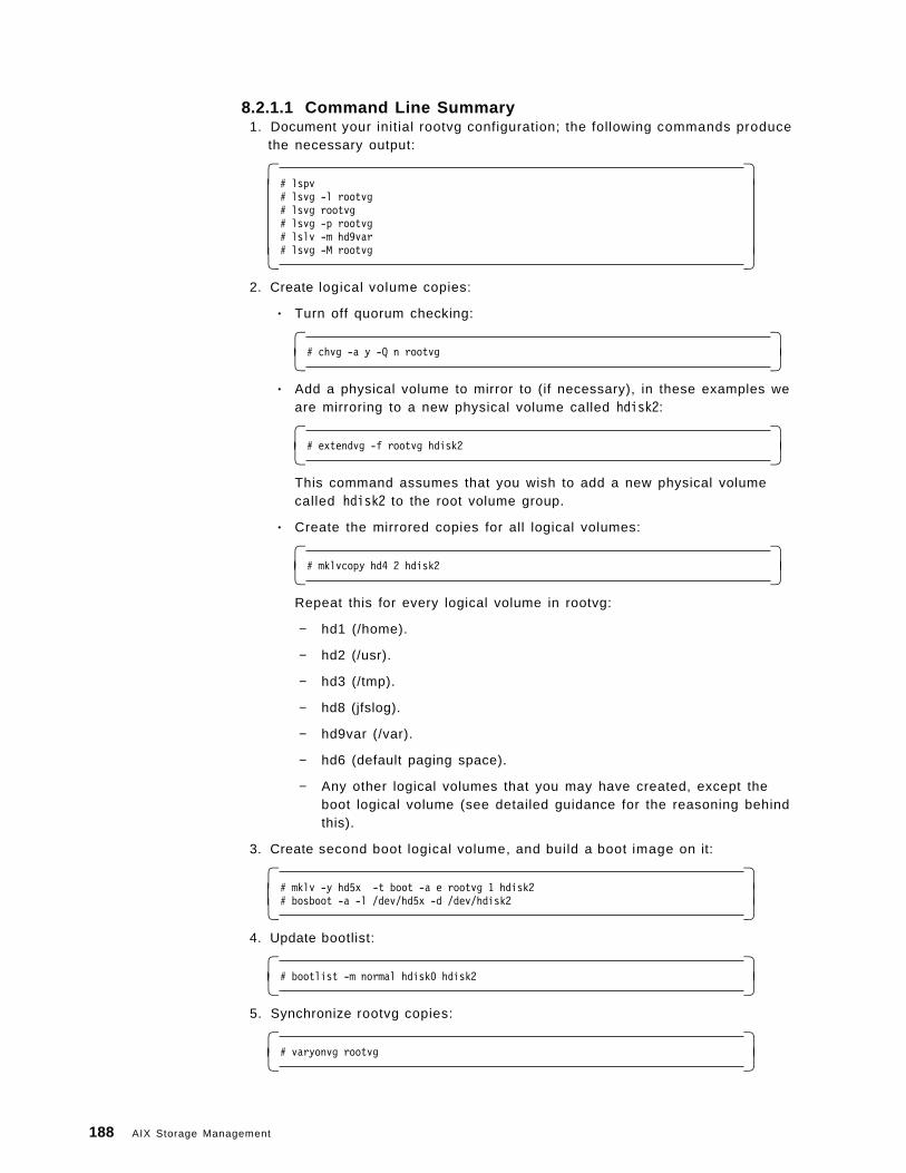
8.2.1.1 Command Line Summary 1. Document your initial rootvg configuration; the following commands produce
the necessary output:
� �# lspv# lsvg -l rootvg# lsvg rootvg# lsvg -p rootvg# lslv -m hd9var# lsvg -M rootvg� �
2. Create logical volume copies:
• Turn off quorum checking:
� �# chvg -a y -Q n rootvg� �
• Add a physical volume to mirror to (if necessary), in these examples weare mirroring to a new physical volume called hdisk2:
� �# extendvg -f rootvg hdisk2� �
This command assumes that you wish to add a new physical volumecalled hdisk2 to the root volume group.
• Create the mirrored copies for all logical volumes:
� �# mklvcopy hd4 2 hdisk2� �
Repeat this for every logical volume in rootvg:
− hd1 (/home).
− hd2 (/usr).
− hd3 (/tmp).
− hd8 (jfslog).
− hd9var (/var).
− hd6 (default paging space).
− Any other logical volumes that you may have created, except theboot logical volume (see detailed guidance for the reasoning behindthis).
3. Create second boot logical volume, and build a boot image on it:
� �# mklv -y hd5x -t boot -a e rootvg 1 hdisk2# bosboot -a -l /dev/hd5x -d /dev/hdisk2� �
4. Update bootlist:
� �# bootlist -m normal hdisk0 hdisk2� �
5. Synchronize rootvg copies:
� �# varyonvg rootvg� �
188 AIX Storage Management
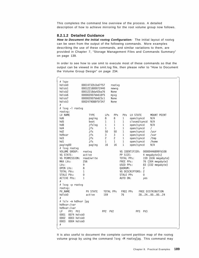
This completes the command line overview of the process. A detaileddescription of how to achieve mirroring for the root volume group now follows.
8.2.1.2 Detailed GuidanceHow to Document the Initial rootvg Configuration: The initial layout of rootvgcan be seen from the output of the following commands. More examplesdescribing the use of these commands, and similar variations to them, areprovided in Chapter 7, “Storage Management Files and Commands Summary”on page 139.
In order to see how to use smit to execute most of these commands so that theoutput can be viewed in the smit.log file, then please refer to “How to Documentthe Volume Group Design” on page 234.
� �# lspvhdisk0 00014732b1bd7f57 rootvghdisk1 0001221800072440 newvghdisk2 00012218da42ba76 Nonehdisk6 000002007bb618f5 myvghdisk7 000002007bb623c1 Nonehdisk3 0002479088f5f347 None## lsvg -l rootvgrootvg:LV NAME TYPE LPs PPs PVs LV STATE MOUNT POINThd6 paging 8 8 1 open/syncd N/Ahd5 boot 1 1 1 closed/syncd N/Ahd8 jfslog 1 1 1 open/syncd N/Ahd4 jfs 1 1 1 open/syncd /hd2 jfs 50 50 1 open/syncd /usrhd9var jfs 3 3 1 open/syncd /varhd3 jfs 2 2 1 open/syncd /tmphd1 jfs 1 1 1 open/syncd /homepaging00 paging 16 16 1 open/syncd N/A# lsvg rootvgVOLUME GROUP: rootvg VG IDENTIFIER: 00000446899fd108VG STATE: active PP SIZE: 4 megabyte(s)VG PERMISSION: read/write TOTAL PPs: 159 (636 megabyte)MAX LVs: 256 FREE PPs: 76 (304 megabyte)LVs: 9 USED PPs: 83 (332 megabyte)OPEN LVs: 8 QUORUM: 2TOTAL PVs: 1 VG DESCRIPTORS: 2STALE PVs: 0 STALE PPs 0ACTIVE PVs: 1 AUTO ON: yes## lsvg -p rootvgrootvg:PV_NAME PV STATE TOTAL PPs FREE PPs FREE DISTRIBUTIONhdisk0 active 159 76 28..24..00..00..24## lslv -m hd9var |pghd9var:/varhd9var:/varLP PP1 PV1 PP2 PV2 PP3 PV30001 0074 hdisk00002 0003 hdisk00003 0004 hdisk0#� �
It is also useful to document the complete current partition map of the rootvgvolume group by using the command lsvg -M rootvg|pg. This command may
Chapter 8. Practical Examples 189
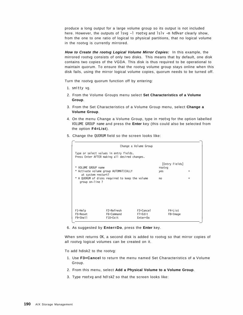
produce a long output for a large volume group so its output is not includedhere. However, the outputs of lsvg -l rootvg and lslv -m hd9var clearly show,from the one to one ratio of logical to physical partitions, that no logical volumein the rootvg is currently mirrored.
How to Create the rootvg Logical Volume Mirror Copies: In this example, themirrored rootvg consists of only two disks. This means that by default, one diskcontains two copies of the VGDA. This disk is thus required to be operational tomaintain quorum. To ensure that the rootvg volume group stays online when thisdisk fails, using the mirror logical volume copies, quorum needs to be turned off.
Turn the rootvg quorum function off by entering:
1. smitty vg.
2. From the Volume Groups menu select Set Characteristics of a VolumeGroup .
3. From the Set Characteristics of a Volume Group menu, select Change aVolume Group .
4. On the menu Change a Volume Group, type in rootvg for the option labelledVOLUME GROUP name and press the Enter key (this could also be selected fromthe option F4=List ).
5. Change the QUORUM field so the screen looks like:
� �Change a Volume Group
Type or select values in entry fields.Press Enter AFTER making all desired changes.
[Entry Fields]* VOLUME GROUP name rootvg* Activate volume group AUTOMATICALLY yes +
at system restart?* A QUORUM of disks required to keep the volume no +
group on-line ?
F1=Help F2=Refresh F3=Cancel F4=ListF5=Reset F6=Command F7=Edit F8=ImageF9=Shell F10=Exit Enter=Do� �
6. As suggested by Enter=Do , press the Enter key.
When smit returns OK, a second disk is added to rootvg so that mirror copies ofall rootvg logical volumes can be created on it.
To add hdisk2 to the rootvg:
1. Use F3=Cancel to return the menu named Set Characteristics of a VolumeGroup.
2. From this menu, select Add a Physical Volume to a Volume Group .
3. Type rootvg and hdisk2 so that the screen looks like:
190 AIX Storage Management
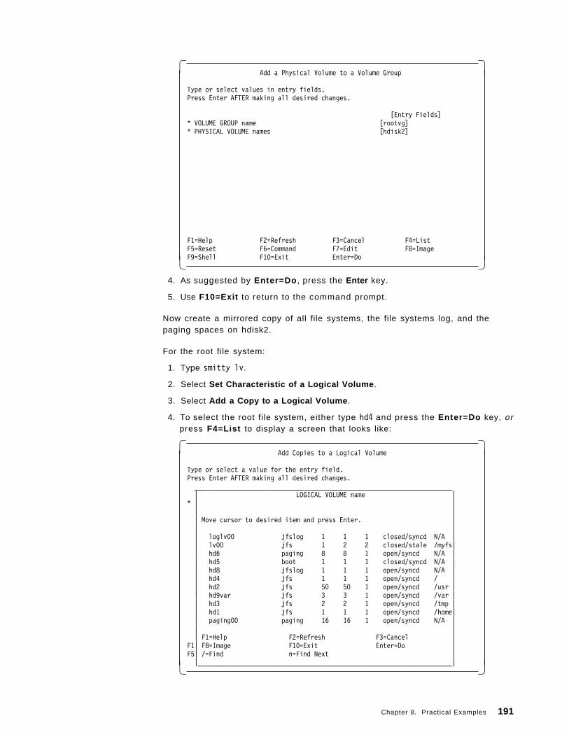
� �Add a Physical Volume to a Volume Group
Type or select values in entry fields.Press Enter AFTER making all desired changes.
[Entry Fields]* VOLUME GROUP name [rootvg]* PHYSICAL VOLUME names [hdisk2]
F1=Help F2=Refresh F3=Cancel F4=ListF5=Reset F6=Command F7=Edit F8=ImageF9=Shell F10=Exit Enter=Do� �
4. As suggested by Enter=Do , press the Enter key.
5. Use F10=Exit to return to the command prompt.
Now create a mirrored copy of all file systems, the file systems log, and thepaging spaces on hdisk2.
For the root file system:
1. Type smitty lv.
2. Select Set Characteristic of a Logical Volume .
3. Select Add a Copy to a Logical Volume .
4. To select the root file system, either type hd4 and press the Enter=Do key, orpress F4=List to display a screen that looks like:
� �Add Copies to a Logical Volume
Type or select a value for the entry field.Press Enter AFTER making all desired changes._______________________________________________________________________| LOGICAL VOLUME name |
* | || || Move cursor to desired item and press Enter. || || loglv00 jfslog 1 1 1 closed/syncd N/A || lv00 jfs 1 2 2 closed/stale /myfs|| hd6 paging 8 8 1 open/syncd N/A || hd5 boot 1 1 1 closed/syncd N/A || hd8 jfslog 1 1 1 open/syncd N/A || hd4 jfs 1 1 1 open/syncd / || hd2 jfs 50 50 1 open/syncd /usr || hd9var jfs 3 3 1 open/syncd /var || hd3 jfs 2 2 1 open/syncd /tmp || hd1 jfs 1 1 1 open/syncd /home|| paging00 paging 16 16 1 open/syncd N/A || || F1=Help F2=Refresh F3=Cancel |
F1| F8=Image F10=Exit Enter=Do |F5| /=Find n=Find Next ||______________________________________________________________________|� �
Chapter 8. Practical Examples 191
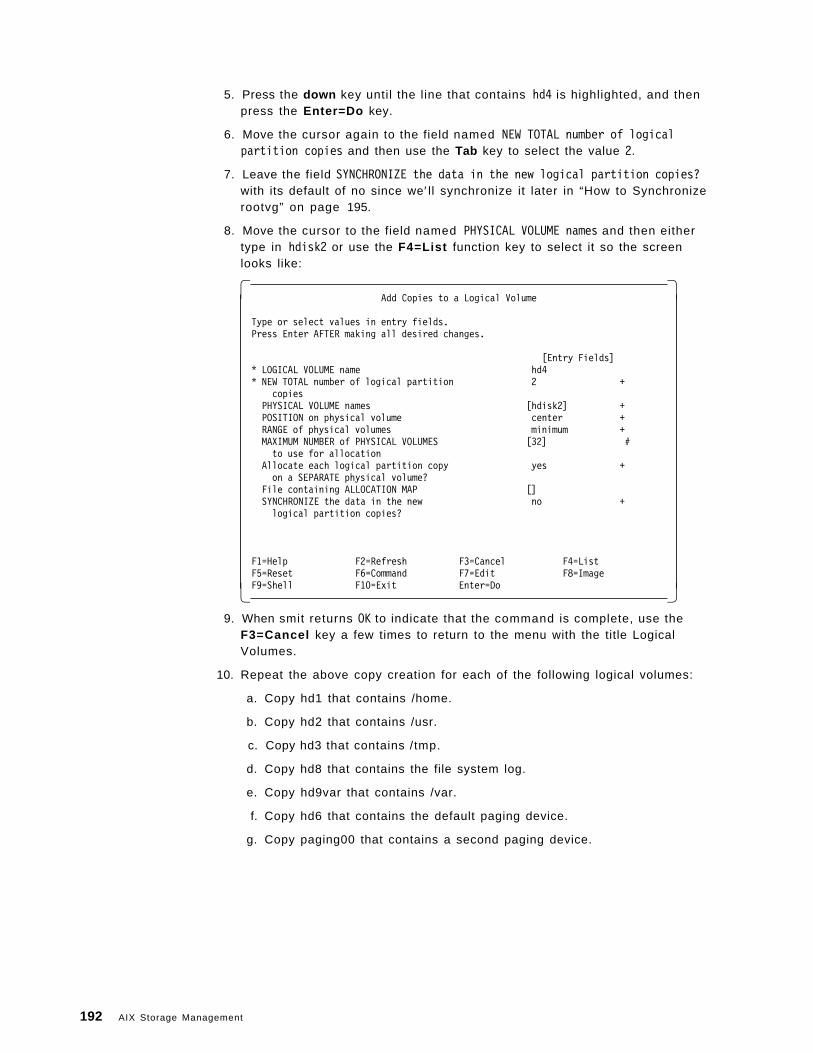
5. Press the down key until the line that contains hd4 is highlighted, and thenpress the Enter=Do key.
6. Move the cursor again to the field named NEW TOTAL number of logicalpartition copies and then use the Tab key to select the value 2.
7. Leave the field SYNCHRONIZE the data in the new logical partition copies?with its default of no since we′ ll synchronize it later in “How to Synchronizerootvg” on page 195.
8. Move the cursor to the field named PHYSICAL VOLUME names and then eithertype in hdisk2 or use the F4=List function key to select it so the screenlooks like:
� �Add Copies to a Logical Volume
Type or select values in entry fields.Press Enter AFTER making all desired changes.
[Entry Fields]* LOGICAL VOLUME name hd4* NEW TOTAL number of logical partition 2 +
copiesPHYSICAL VOLUME names [hdisk2] +POSITION on physical volume center +RANGE of physical volumes minimum +MAXIMUM NUMBER of PHYSICAL VOLUMES [32] #to use for allocation
Allocate each logical partition copy yes +on a SEPARATE physical volume?
File containing ALLOCATION MAP []SYNCHRONIZE the data in the new no +logical partition copies?
F1=Help F2=Refresh F3=Cancel F4=ListF5=Reset F6=Command F7=Edit F8=ImageF9=Shell F10=Exit Enter=Do� �
9. When smit returns OK to indicate that the command is complete, use theF3=Cancel key a few times to return to the menu with the title LogicalVolumes.
10. Repeat the above copy creation for each of the following logical volumes:
a. Copy hd1 that contains /home.
b. Copy hd2 that contains /usr.
c. Copy hd3 that contains /tmp.
d. Copy hd8 that contains the file system log.
e. Copy hd9var that contains /var.
f. Copy hd6 that contains the default paging device.
g. Copy paging00 that contains a second paging device.
192 AIX Storage Management
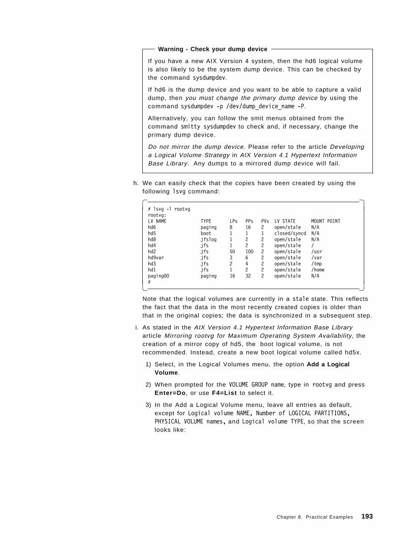
Warning - Check your dump device
If you have a new AIX Version 4 system, then the hd6 logical volumeis also likely to be the system dump device. This can be checked bythe command sysdumpdev.
If hd6 is the dump device and you want to be able to capture a validdump, then you must change the primary dump device by using thecommand sysdumpdev -p /dev/dump_device_name -P.
Alternatively, you can follow the smit menus obtained from thecommand smitty sysdumpdev to check and, if necessary, change theprimary dump device.
Do not mirror the dump device. Please refer to the article Developinga Logical Volume Strategy in AIX Version 4.1 Hypertext InformationBase Library. Any dumps to a mirrored dump device will fail.
h. We can easily check that the copies have been created by using thefollowing lsvg command:
� �# lsvg -l rootvgrootvg:LV NAME TYPE LPs PPs PVs LV STATE MOUNT POINThd6 paging 8 16 2 open/stale N/Ahd5 boot 1 1 1 closed/syncd N/Ahd8 jfslog 1 2 2 open/stale N/Ahd4 jfs 1 2 2 open/stale /hd2 jfs 50 100 2 open/stale /usrhd9var jfs 3 6 2 open/stale /varhd3 jfs 2 4 2 open/stale /tmphd1 jfs 1 2 2 open/stale /homepaging00 paging 16 32 2 open/stale N/A#� �
Note that the logical volumes are currently in a stale state. This reflectsthe fact that the data in the most recently created copies is older thanthat in the original copies; the data is synchronized in a subsequent step.
i. As stated in the AIX Version 4.1 Hypertext Information Base Libraryarticle Mirroring rootvg for Maximum Operating System Availability, thecreation of a mirror copy of hd5, the boot logical volume, is notrecommended. Instead, create a new boot logical volume called hd5x.
1) Select, in the Logical Volumes menu, the option Add a LogicalVolume .
2) When prompted for the VOLUME GROUP name, type in rootvg and pressEnter=Do , or use F4=List to select it.
3) In the Add a Logical Volume menu, leave all entries as default,except for Logical volume NAME, Number of LOGICAL PARTITIONS,PHYSICAL VOLUME names, and Logical volume TYPE, so that the screenlooks like:
Chapter 8. Practical Examples 193
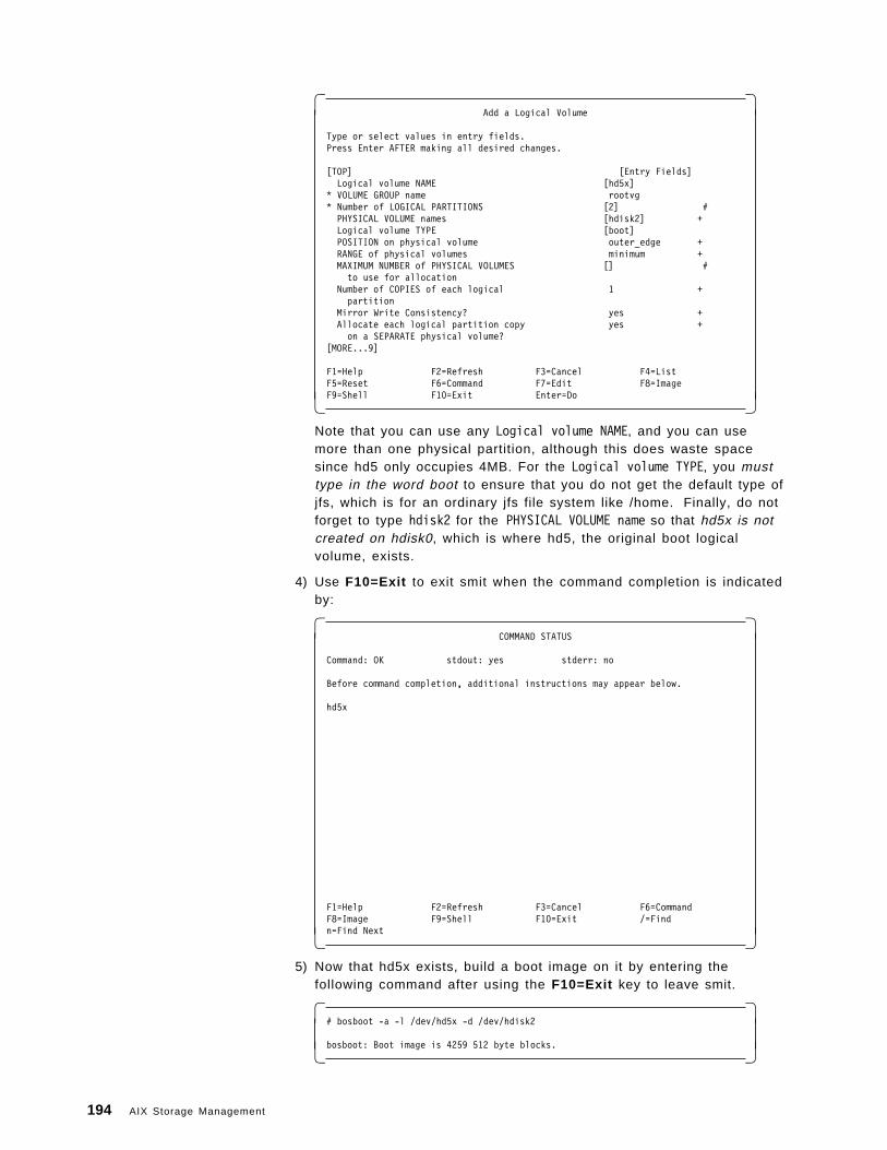
� �Add a Logical Volume
Type or select values in entry fields.Press Enter AFTER making all desired changes.
[TOP] [Entry Fields]Logical volume NAME [hd5x]
* VOLUME GROUP name rootvg* Number of LOGICAL PARTITIONS [2] #
PHYSICAL VOLUME names [hdisk2] +Logical volume TYPE [boot]POSITION on physical volume outer_edge +RANGE of physical volumes minimum +MAXIMUM NUMBER of PHYSICAL VOLUMES [] #
to use for allocationNumber of COPIES of each logical 1 +
partitionMirror Write Consistency? yes +Allocate each logical partition copy yes +
on a SEPARATE physical volume?[MORE...9]
F1=Help F2=Refresh F3=Cancel F4=ListF5=Reset F6=Command F7=Edit F8=ImageF9=Shell F10=Exit Enter=Do� �
Note that you can use any Logical volume NAME, and you can usemore than one physical partition, although this does waste spacesince hd5 only occupies 4MB. For the Logical volume TYPE, you musttype in the word boot to ensure that you do not get the default type ofjfs, which is for an ordinary jfs file system like /home. Finally, do notforget to type hdisk2 for the PHYSICAL VOLUME name so that hd5x is notcreated on hdisk0, which is where hd5, the original boot logicalvolume, exists.
4) Use F10=Exit to exit smit when the command completion is indicatedby:
� �COMMAND STATUS
Command: OK stdout: yes stderr: no
Before command completion, additional instructions may appear below.
hd5x
F1=Help F2=Refresh F3=Cancel F6=CommandF8=Image F9=Shell F10=Exit /=Findn=Find Next� �
5) Now that hd5x exists, build a boot image on it by entering thefollowing command after using the F10=Exit key to leave smit.
� �# bosboot -a -l /dev/hd5x -d /dev/hdisk2
bosboot: Boot image is 4259 512 byte blocks.� �
194 AIX Storage Management
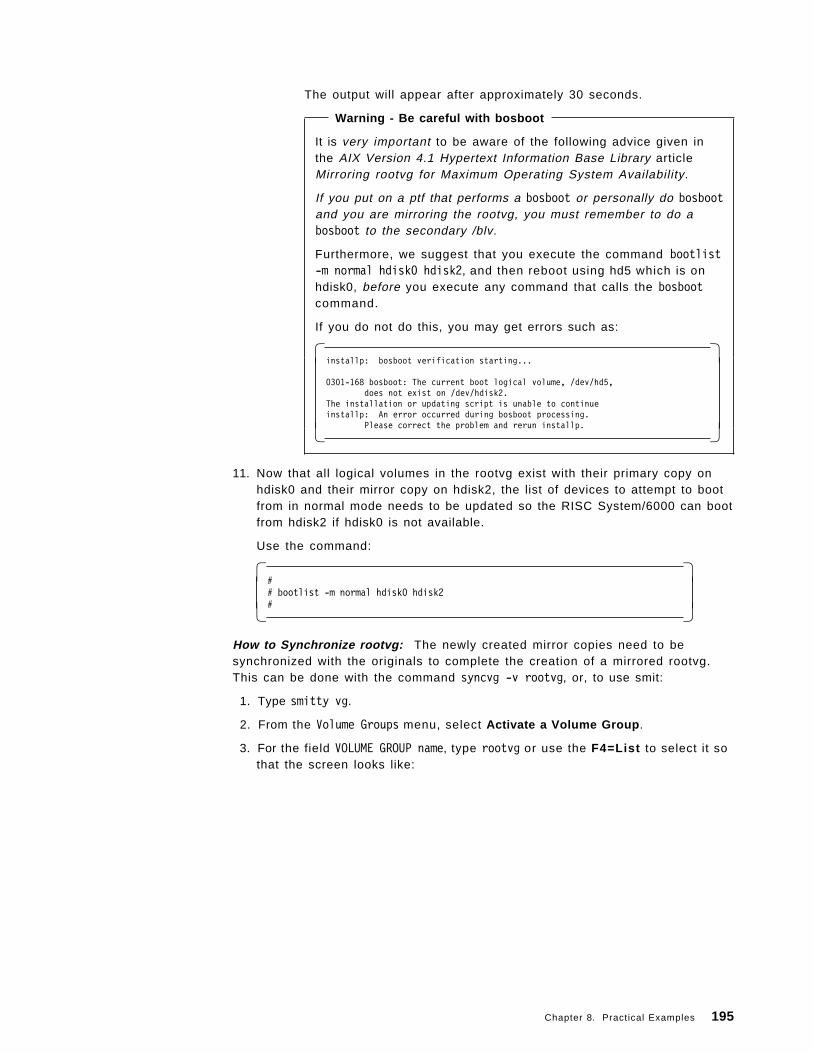
The output will appear after approximately 30 seconds.
Warning - Be careful with bosboot
It is very important to be aware of the following advice given inthe AIX Version 4.1 Hypertext Information Base Library articleMirroring rootvg for Maximum Operating System Availability.
If you put on a ptf that performs a bosboot or personally do bosbootand you are mirroring the rootvg, you must remember to do abosboot to the secondary /blv.
Furthermore, we suggest that you execute the command bootlist-m normal hdisk0 hdisk2, and then reboot using hd5 which is onhdisk0, before you execute any command that calls the bosbootcommand.
If you do not do this, you may get errors such as:
� �installp: bosboot verification starting...
0301-168 bosboot: The current boot logical volume, /dev/hd5,does not exist on /dev/hdisk2.
The installation or updating script is unable to continueinstallp: An error occurred during bosboot processing.
Please correct the problem and rerun installp.� �
11. Now that all logical volumes in the rootvg exist with their primary copy onhdisk0 and their mirror copy on hdisk2, the list of devices to attempt to bootfrom in normal mode needs to be updated so the RISC System/6000 can bootfrom hdisk2 if hdisk0 is not available.
Use the command:
� �## bootlist -m normal hdisk0 hdisk2#� �
How to Synchronize rootvg: The newly created mirror copies need to besynchronized with the originals to complete the creation of a mirrored rootvg.This can be done with the command syncvg -v rootvg, or, to use smit:
1. Type smitty vg.
2. From the Volume Groups menu, select Activate a Volume Group .
3. For the field VOLUME GROUP name, type rootvg or use the F4=List to select it sothat the screen looks like:
Chapter 8. Practical Examples 195
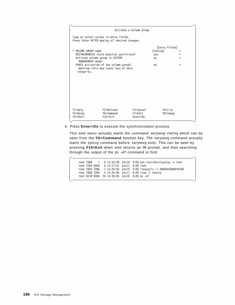
� �Activate a Volume Group
Type or select values in entry fields.Press Enter AFTER making all desired changes.
[Entry Fields]* VOLUME GROUP name [rootvg] +RESYNCHRONIZE stale physical partitions? yes +Activate volume group in SYSTEM no +MANAGEMENT mode?
FORCE activation of the volume group? no +Warning--this may cause loss of dataintegrity.
F1=Help F2=Refresh F3=Cancel F4=ListF5=Reset F6=Command F7=Edit F8=ImageF9=Shell F10=Exit Enter=Do� �
4. Press Enter=Do to execute the synchronization process.
This smit menu actually starts the command varyonvg rootvg which can beseen from the F6=Command function key. The varyonvg command actuallystarts the syncvg command before varyonvg exits. This can be seen bypressing F10=Exit when smit returns an OK prompt, and then searchingthrough the output of the ps -ef command to find:
� �root 7066 1 0 13:33:36 pts/0 0:00 bsh /usr/sbin/syncvg -v rootroot 7264 6494 0 13:17:41 pts/1 0:00 -kshroot 7604 7066 1 13:34:50 pts/0 0:00 lresynclv -l 00000446899fd108root 7858 7264 5 13:34:46 pts/1 0:00 lsvg -l rootvgroot 8118 6056 34 13:35:05 pts/0 0:00 ps -ef� �
196 AIX Storage Management
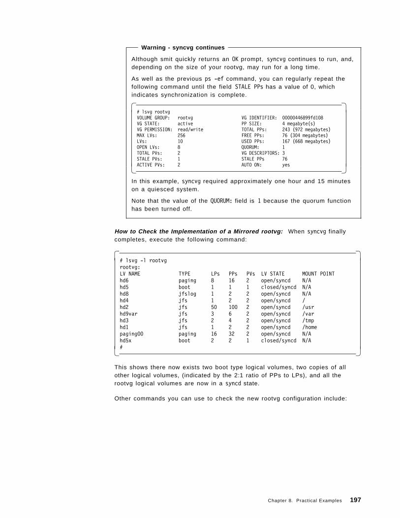
Warning - syncvg continues
Although smit quickly returns an OK prompt, syncvg continues to run, and,depending on the size of your rootvg, may run for a long time.
As well as the previous ps -ef command, you can regularly repeat thefollowing command until the field STALE PPs has a value of 0, whichindicates synchronization is complete.
� �# lsvg rootvgVOLUME GROUP: rootvg VG IDENTIFIER: 00000446899fd108VG STATE: active PP SIZE: 4 megabyte(s)VG PERMISSION: read/write TOTAL PPs: 243 (972 megabytes)MAX LVs: 256 FREE PPs: 76 (304 megabytes)LVs: 10 USED PPs: 167 (668 megabytes)OPEN LVs: 8 QUORUM: 1TOTAL PVs: 2 VG DESCRIPTORS: 3STALE PVs: 1 STALE PPs 76ACTIVE PVs: 2 AUTO ON: yes� �
In this example, syncvg required approximately one hour and 15 minuteson a quiesced system.
Note that the value of the QUORUM: field is 1 because the quorum functionhas been turned off.
How to Check the Implementation of a Mirrored rootvg: When syncvg finallycompletes, execute the following command:
� �# lsvg -l rootvgrootvg:LV NAME TYPE LPs PPs PVs LV STATE MOUNT POINThd6 paging 8 16 2 open/syncd N/Ahd5 boot 1 1 1 closed/syncd N/Ahd8 jfslog 1 2 2 open/syncd N/Ahd4 jfs 1 2 2 open/syncd /hd2 jfs 50 100 2 open/syncd /usrhd9var jfs 3 6 2 open/syncd /varhd3 jfs 2 4 2 open/syncd /tmphd1 jfs 1 2 2 open/syncd /homepaging00 paging 16 32 2 open/syncd N/Ahd5x boot 2 2 1 closed/syncd N/A#� �
This shows there now exists two boot type logical volumes, two copies of allother logical volumes, (indicated by the 2:1 ratio of PPs to LPs), and all therootvg logical volumes are now in a syncd state.
Other commands you can use to check the new rootvg configuration include:
Chapter 8. Practical Examples 197
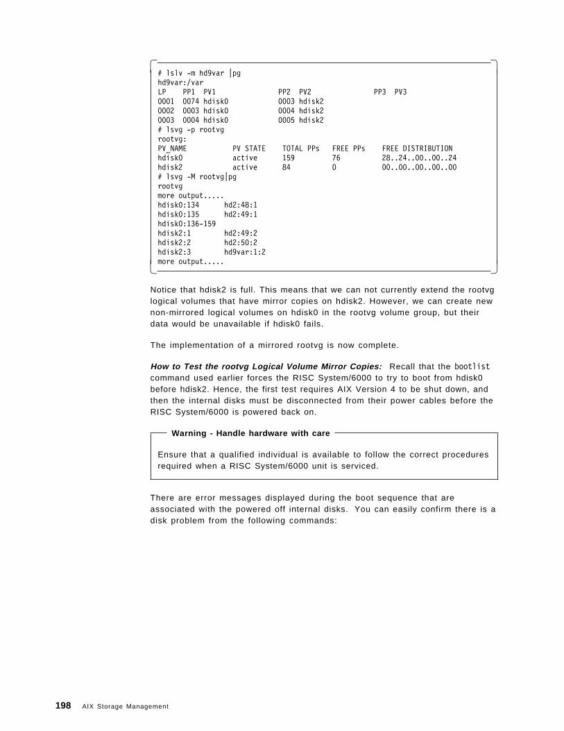
� �# lslv -m hd9var |pghd9var:/varLP PP1 PV1 PP2 PV2 PP3 PV30001 0074 hdisk0 0003 hdisk20002 0003 hdisk0 0004 hdisk20003 0004 hdisk0 0005 hdisk2# lsvg -p rootvgrootvg:PV_NAME PV STATE TOTAL PPs FREE PPs FREE DISTRIBUTIONhdisk0 active 159 76 28..24..00..00..24hdisk2 active 84 0 00..00..00..00..00# lsvg -M rootvg|pgrootvgmore output.....hdisk0:134 hd2:48:1hdisk0:135 hd2:49:1hdisk0:136-159hdisk2:1 hd2:49:2hdisk2:2 hd2:50:2hdisk2:3 hd9var:1:2more output.....� �
Notice that hdisk2 is full. This means that we can not currently extend the rootvglogical volumes that have mirror copies on hdisk2. However, we can create newnon-mirrored logical volumes on hdisk0 in the rootvg volume group, but theirdata would be unavailable if hdisk0 fails.
The implementation of a mirrored rootvg is now complete.
How to Test the rootvg Logical Volume Mirror Copies: Recall that the bootlistcommand used earlier forces the RISC System/6000 to try to boot from hdisk0before hdisk2. Hence, the first test requires AIX Version 4 to be shut down, andthen the internal disks must be disconnected from their power cables before theRISC System/6000 is powered back on.
Warning - Handle hardware with care
Ensure that a qualified individual is available to follow the correct proceduresrequired when a RISC System/6000 unit is serviced.
There are error messages displayed during the boot sequence that areassociated with the powered off internal disks. You can easily confirm there is adisk problem from the following commands:
198 AIX Storage Management
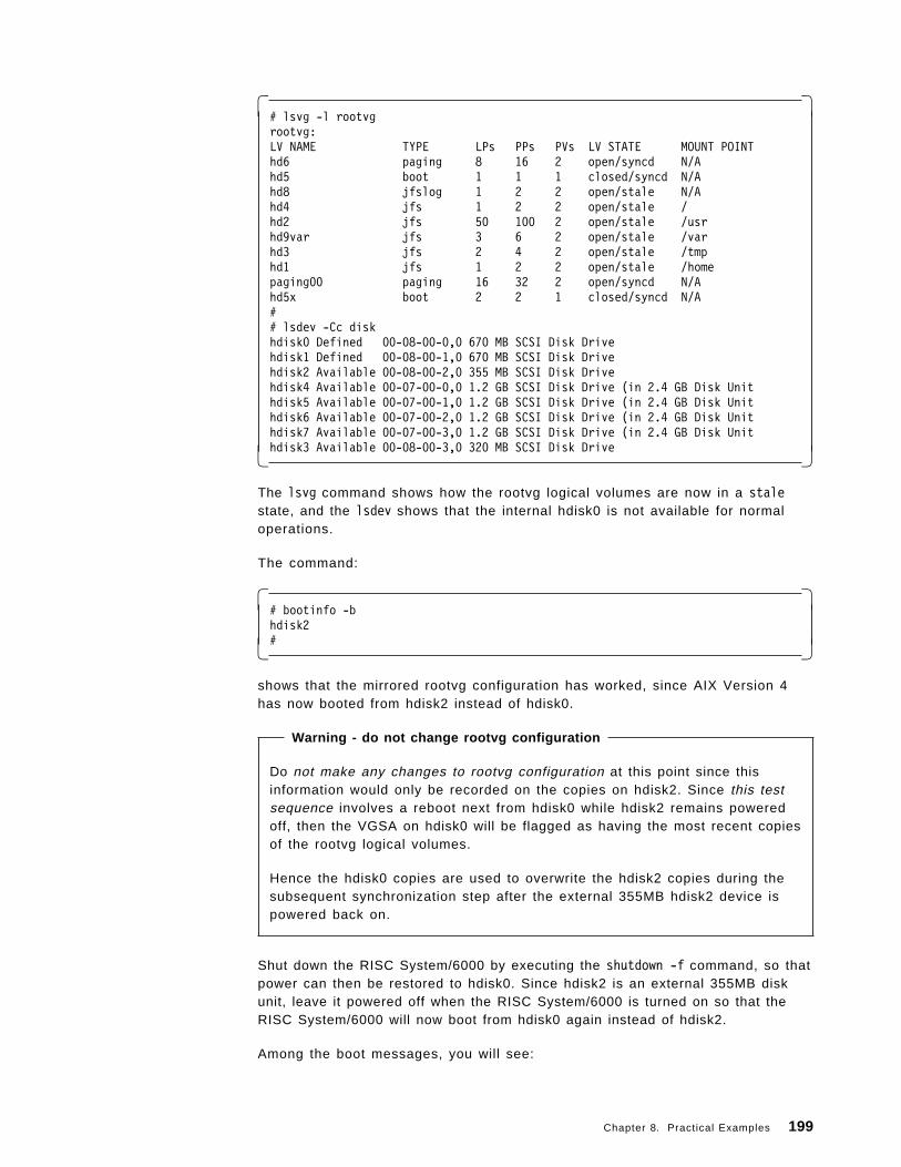
� �# lsvg -l rootvgrootvg:LV NAME TYPE LPs PPs PVs LV STATE MOUNT POINThd6 paging 8 16 2 open/syncd N/Ahd5 boot 1 1 1 closed/syncd N/Ahd8 jfslog 1 2 2 open/stale N/Ahd4 jfs 1 2 2 open/stale /hd2 jfs 50 100 2 open/stale /usrhd9var jfs 3 6 2 open/stale /varhd3 jfs 2 4 2 open/stale /tmphd1 jfs 1 2 2 open/stale /homepaging00 paging 16 32 2 open/syncd N/Ahd5x boot 2 2 1 closed/syncd N/A## lsdev -Cc diskhdisk0 Defined 00-08-00-0,0 670 MB SCSI Disk Drivehdisk1 Defined 00-08-00-1,0 670 MB SCSI Disk Drivehdisk2 Available 00-08-00-2,0 355 MB SCSI Disk Drivehdisk4 Available 00-07-00-0,0 1.2 GB SCSI Disk Drive (in 2.4 GB Disk Unithdisk5 Available 00-07-00-1,0 1.2 GB SCSI Disk Drive (in 2.4 GB Disk Unithdisk6 Available 00-07-00-2,0 1.2 GB SCSI Disk Drive (in 2.4 GB Disk Unithdisk7 Available 00-07-00-3,0 1.2 GB SCSI Disk Drive (in 2.4 GB Disk Unithdisk3 Available 00-08-00-3,0 320 MB SCSI Disk Drive� �
The lsvg command shows how the rootvg logical volumes are now in a stalestate, and the lsdev shows that the internal hdisk0 is not available for normaloperations.
The command:
� �# bootinfo -bhdisk2#� �
shows that the mirrored rootvg configuration has worked, since AIX Version 4has now booted from hdisk2 instead of hdisk0.
Warning - do not change rootvg configuration
Do not make any changes to rootvg configuration at this point since thisinformation would only be recorded on the copies on hdisk2. Since this testsequence involves a reboot next from hdisk0 while hdisk2 remains poweredoff, then the VGSA on hdisk0 will be flagged as having the most recent copiesof the rootvg logical volumes.
Hence the hdisk0 copies are used to overwrite the hdisk2 copies during thesubsequent synchronization step after the external 355MB hdisk2 device ispowered back on.
Shut down the RISC System/6000 by executing the shutdown -f command, so thatpower can then be restored to hdisk0. Since hdisk2 is an external 355MB diskunit, leave it powered off when the RISC System/6000 is turned on so that theRISC System/6000 will now boot from hdisk0 again instead of hdisk2.
Among the boot messages, you will see:
Chapter 8. Practical Examples 199
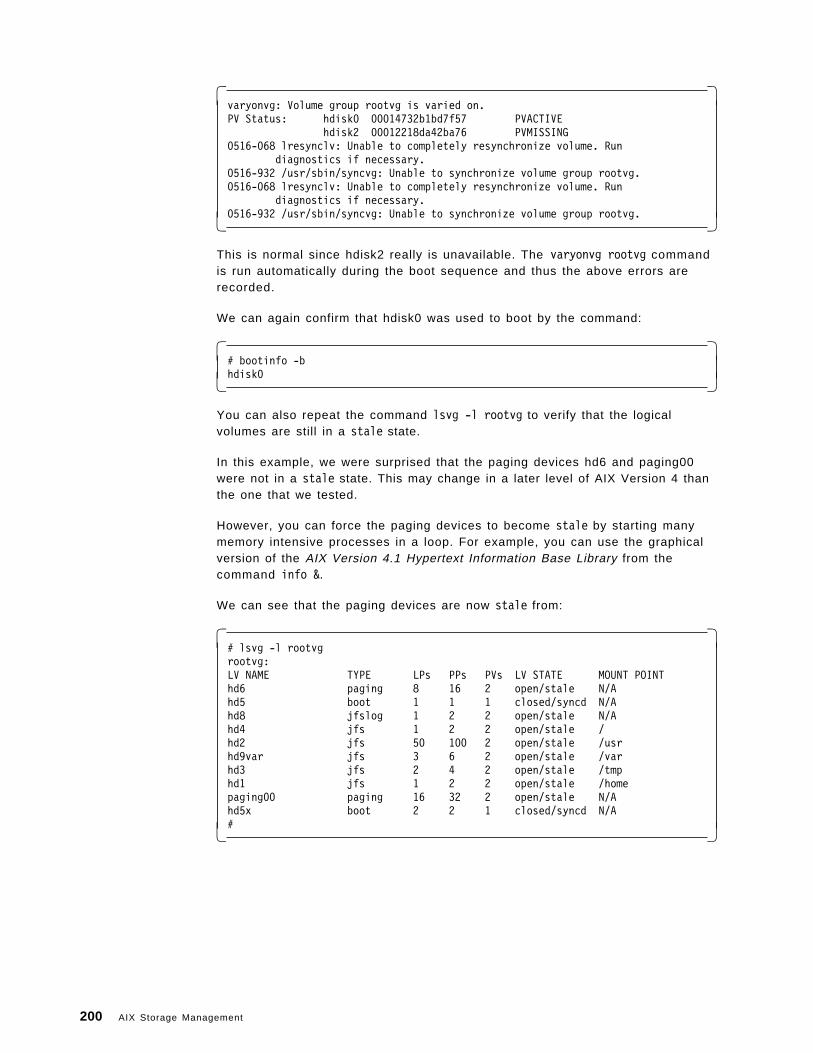
� �varyonvg: Volume group rootvg is varied on.PV Status: hdisk0 00014732b1bd7f57 PVACTIVE
hdisk2 00012218da42ba76 PVMISSING0516-068 lresynclv: Unable to completely resynchronize volume. Run
diagnostics if necessary.0516-932 /usr/sbin/syncvg: Unable to synchronize volume group rootvg.0516-068 lresynclv: Unable to completely resynchronize volume. Run
diagnostics if necessary.0516-932 /usr/sbin/syncvg: Unable to synchronize volume group rootvg.� �
This is normal since hdisk2 really is unavailable. The varyonvg rootvg commandis run automatically during the boot sequence and thus the above errors arerecorded.
We can again confirm that hdisk0 was used to boot by the command:
� �# bootinfo -bhdisk0� �
You can also repeat the command lsvg -l rootvg to verify that the logicalvolumes are still in a stale state.
In this example, we were surprised that the paging devices hd6 and paging00were not in a stale state. This may change in a later level of AIX Version 4 thanthe one that we tested.
However, you can force the paging devices to become stale by starting manymemory intensive processes in a loop. For example, you can use the graphicalversion of the AIX Version 4.1 Hypertext Information Base Library from thecommand info &.
We can see that the paging devices are now stale from:
� �# lsvg -l rootvgrootvg:LV NAME TYPE LPs PPs PVs LV STATE MOUNT POINThd6 paging 8 16 2 open/stale N/Ahd5 boot 1 1 1 closed/syncd N/Ahd8 jfslog 1 2 2 open/stale N/Ahd4 jfs 1 2 2 open/stale /hd2 jfs 50 100 2 open/stale /usrhd9var jfs 3 6 2 open/stale /varhd3 jfs 2 4 2 open/stale /tmphd1 jfs 1 2 2 open/stale /homepaging00 paging 16 32 2 open/stale N/Ahd5x boot 2 2 1 closed/syncd N/A#� �
200 AIX Storage Management
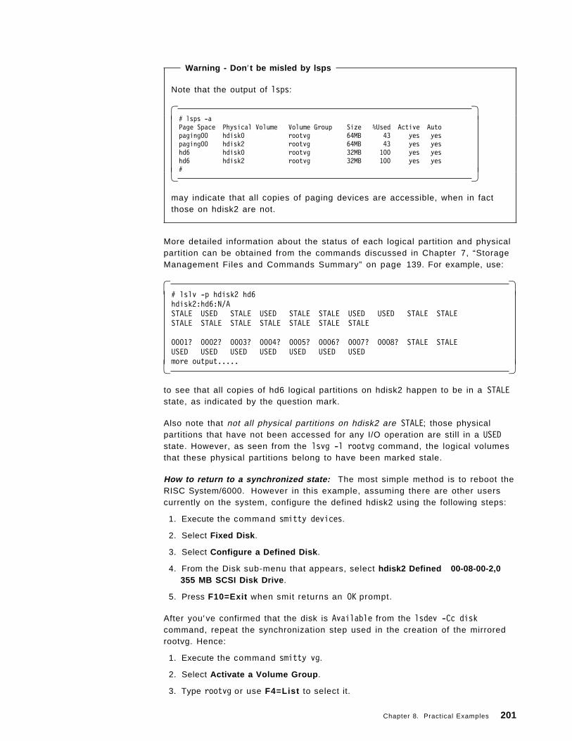
Warning - Don ′ t be misled by lsps
Note that the output of lsps:
� �# lsps -aPage Space Physical Volume Volume Group Size %Used Active Autopaging00 hdisk0 rootvg 64MB 43 yes yespaging00 hdisk2 rootvg 64MB 43 yes yeshd6 hdisk0 rootvg 32MB 100 yes yeshd6 hdisk2 rootvg 32MB 100 yes yes#� �
may indicate that all copies of paging devices are accessible, when in factthose on hdisk2 are not.
More detailed information about the status of each logical partition and physicalpartition can be obtained from the commands discussed in Chapter 7, “StorageManagement Files and Commands Summary” on page 139. For example, use:
� �# lslv -p hdisk2 hd6hdisk2:hd6:N/ASTALE USED STALE USED STALE STALE USED USED STALE STALESTALE STALE STALE STALE STALE STALE STALE
0001? 0002? 0003? 0004? 0005? 0006? 0007? 0008? STALE STALEUSED USED USED USED USED USED USEDmore output.....� �
to see that all copies of hd6 logical partitions on hdisk2 happen to be in a STALEstate, as indicated by the question mark.
Also note that not all physical partitions on hdisk2 are STALE; those physicalpartitions that have not been accessed for any I/O operation are still in a USEDstate. However, as seen from the lsvg -l rootvg command, the logical volumesthat these physical partitions belong to have been marked stale.
How to return to a synchronized state: The most simple method is to reboot theRISC System/6000. However in this example, assuming there are other userscurrently on the system, configure the defined hdisk2 using the following steps:
1. Execute the command smitty devices.
2. Select Fixed Disk .
3. Select Configure a Defined Disk .
4. From the Disk sub-menu that appears, select hdisk2 Defined 00-08-00-2,0355 MB SCSI Disk Drive .
5. Press F10=Exit when smit returns an OK prompt.
After you′ve confirmed that the disk is Available from the lsdev -Cc diskcommand, repeat the synchronization step used in the creation of the mirroredrootvg. Hence:
1. Execute the command smitty vg.
2. Select Activate a Volume Group .
3. Type rootvg or use F4=List to select it.
Chapter 8. Practical Examples 201
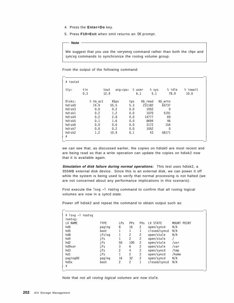
4. Press the Enter=Do key.
5. Press F10=Exit when smit returns an OK prompt.
Note
We suggest that you use the varyonvg command rather than both the chpv andsyncvg commands to synchronize the rootvg volume group.
From the output of the following command:
� �# iostat
tty: tin tout avg-cpu: % user % sys % idle % iowait0.3 12.9 6.1 5.1 78.9 10.0
Disks: % tm_act Kbps tps Kb_read Kb_wrtnhdisk0 14.9 55.5 5.3 231182 65737hdisk3 0.0 0.2 0.0 1052 0hdisk1 0.2 1.2 0.0 1070 5191hdisk4 0.2 2.8 0.0 14777 69hdisk5 0.1 1.6 0.0 8694 46hdisk6 0.0 0.6 0.0 3172 154hdisk7 0.0 0.2 0.0 1052 0hdisk2 1.2 10.9 0.1 43 58171#� �
we can see that, as discussed earlier, the copies on hdisk0 are most recent andare being read so that a write operation can update the copies on hdisk2 nowthat it is available again.
Simulation of disk failure during normal operations: This test uses hdisk2, a355MB external disk device. Since this is an external disk, we can power it offwhile the system is being used to verify that normal processing is not halted (weare not concerned about any performance implications in this scenario).
First execute the lsvg -l rootvg command to confirm that all rootvg logicalvolumes are now in a syncd state.
Power off hdisk2 and repeat the command to obtain output such as:
� �# lsvg -l rootvgrootvg:LV NAME TYPE LPs PPs PVs LV STATE MOUNT POINThd6 paging 8 16 2 open/syncd N/Ahd5 boot 1 1 1 closed/syncd N/Ahd8 jfslog 1 2 2 open/stale N/Ahd4 jfs 1 2 2 open/stale /hd2 jfs 50 100 2 open/stale /usrhd9var jfs 3 6 2 open/stale /varhd3 jfs 2 4 2 open/syncd /tmphd1 jfs 1 2 2 open/syncd /homepaging00 paging 16 32 2 open/syncd N/Ahd5x boot 2 2 1 closed/syncd N/A#� �
Note that not all rootvg logical volumes are now stale.
202 AIX Storage Management
• hd8 is stale because a write occurred to a jfs.
• hd4 is stale because / contains the ODM files that are read to help producethe command output.
• hd2 is stale because /usr contains the lsvg command that is read so that itcan be loaded into RAM and then executed.
• hd9var is stale because there have been some temporary files created sincehdisk2 was powered off.
The other logical volumes are not currently involved in an I/O operation and sothey remain in a syncd state.
Once power is restored to hdisk2, it can again be again synchronized with hdisk0by using the varyonvg rootvg or the corresponding smitty vg selection.
8.3 Storage Subsystem DesignFor this section, it is very beneficial for the reader to become familiar with theconcepts discussed in:
• Chapter 5, “Storage Subsystem Design” on page 79.
• Chapter 6, “General AIX Storage Management” on page 95.
• AIX Version 4.1 System Management Guide: Operating System and Devices,which may be in :cit,AIX Version 4.1 Hypertext Information Base Library onyour system.
• AIX V3.2 Performance Monitoring and Tuning Guide, which may be in AIXVersion 4.1 Hypertext Information Base Library on your system.
• The following AIX Version 4.1 Hypertext Information Base Library articles:
− Developing a Logical Volume Strategy
− Configuring a Storage System for Maximum Performance
− Developing a Volume Group Strategy
− Configuring a Storage System for Maximum Availability
− Create a File System Log on a Dedicated Disk for a User-Defined VolumeGroup
− Backing Up Your System
− Installing BOS from a System Backup
− Logical Volume Storage Overview
− File Systems Overview
Once the available hardware has been reviewed (please refer to 8.1, “Planning”on page 185), the next step in storage subsystem design is to plan and designyour volume group configuration.
Chapter 8. Practical Examples 203
8.3.1 A Volume Group Design ExampleTwo major aims in storage subsystem design are to achieve the optimumperformance for disk access requests (in other words, the fastest disk accesspossible), and also to achieve the highest possible availability (in other words,provide the system with as good a chance as is practically possible that diskaccess requests will not fail). These aims are discussed in more detailelsewhere, but it is important to note at this point that these aims can ofteninterfere with each other. In other words, a high availability configuration willoften result in slower access times to the data that is now stored in a highlyavailable state.
Sometimes, a particular configuration option will be beneficial for bothperformance and availability, but then there is likely to be an associated extracost for that choice. In this example, the price paid for a second SCSI adapterhas bought us the option of placing some disk devices on this second adapter.This can improve performance because the I/O requests workload can now beshared between both adapters. This also improves availability if disk mirroring isimplemented using disks on different adapters, because we would then still haveaccess to one disk if one of the adapters failed.
However, our particular configuration and storage needs does not allow us tofully utilize this benefit. Recall from 8.1, “Planning” on page 185 that for thisexample, we have a total of nine disks to allocate. We have already allocatedone internal 670MB disk and the external 355MB disk to the rootvg volumegroup. We are not interested in the performance of disk I/O for the logicalvolumes in the rootvg, so we′ve allocated the slowest disks for the rootvg. Wedid not use both internal 670MB disks for rootvg because we wanted to be ableto power off a rootvg disk while the system is being used; please refer to 8.2,“rootvg Mirroring - Implementation and Recovery” on page 187.
This leaves us with seven more disks to allocate, two on the SCSI adapter in sloteight, and five on the adapter in slot seven. Ideally, a system with multiple disksshould consist of multiple volume groups; usually such a system should have atleast one non-rootvg volume group.
The guidelines for volume group design are discussed elsewhere, seeChapter 5, “Storage Subsystem Design” on page 79, and also refer to the articleDeveloping a Volume Group Strategy, but for this example, we want to createthree volume groups, primarily for safe and easy maintenance. This allows us todo different storage management related tasks in different volume groups, andhence we can isolate the effects of theses tasks. In other words, a volume groupsynchronization operation will potentially only result in extensive I/O in two orthree disks, instead of say seven disks if they are all grouped together as onevolume group. Multiple volume groups allow journaled file systems to becreated in one volume group, and raw logical volumes can be used bydatabases in another volume group. Also, we can destroy the configuration ofone volume group and its associated components (disks, logical volumes, data)during one example without affecting the integrity of data, file systems, andlogical volumes used in other examples in other volume groups. Finally, wehave the options of implementing different quorum characteristics in the differentvolume groups, and we can use a different physical partition size for eachvolume group.
204 AIX Storage Management
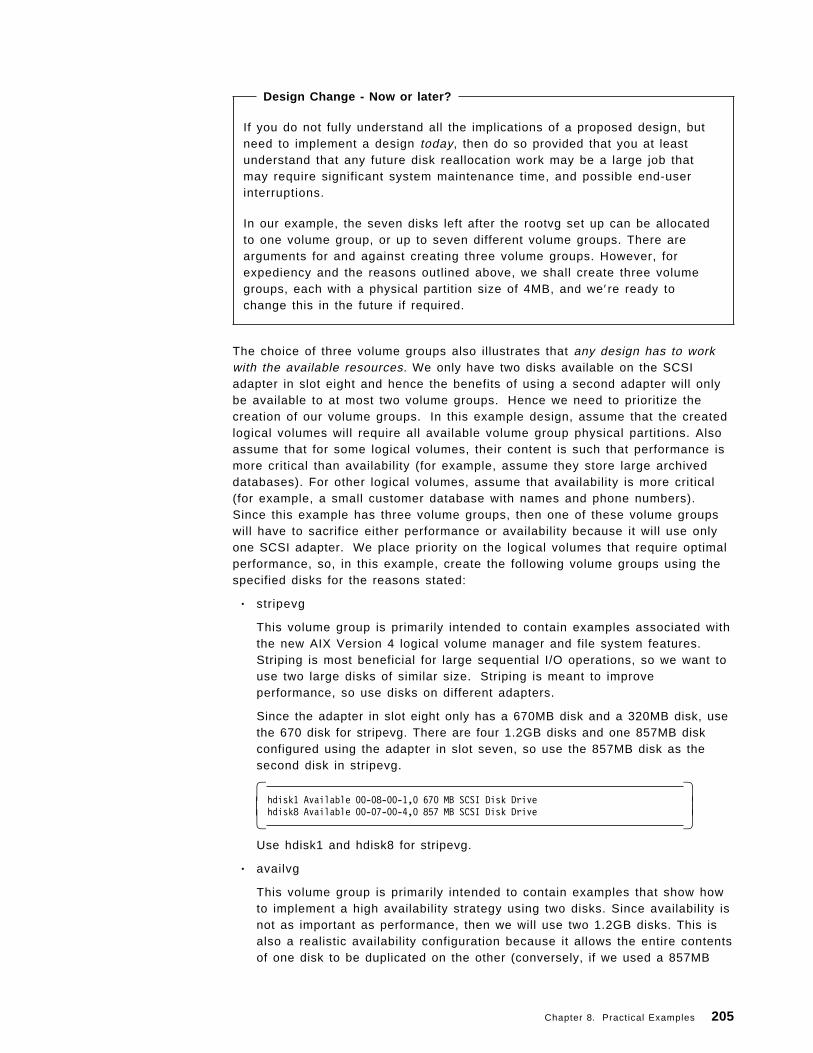
Design Change - Now or later?
If you do not fully understand all the implications of a proposed design, butneed to implement a design today, then do so provided that you at leastunderstand that any future disk reallocation work may be a large job thatmay require significant system maintenance time, and possible end-userinterruptions.
In our example, the seven disks left after the rootvg set up can be allocatedto one volume group, or up to seven different volume groups. There arearguments for and against creating three volume groups. However, forexpediency and the reasons outlined above, we shall create three volumegroups, each with a physical partition size of 4MB, and we′re ready tochange this in the future if required.
The choice of three volume groups also illustrates that any design has to workwith the available resources. We only have two disks available on the SCSIadapter in slot eight and hence the benefits of using a second adapter will onlybe available to at most two volume groups. Hence we need to prioritize thecreation of our volume groups. In this example design, assume that the createdlogical volumes will require all available volume group physical partitions. Alsoassume that for some logical volumes, their content is such that performance ismore critical than availability (for example, assume they store large archiveddatabases). For other logical volumes, assume that availability is more critical(for example, a small customer database with names and phone numbers).Since this example has three volume groups, then one of these volume groupswill have to sacrifice either performance or availability because it will use onlyone SCSI adapter. We place priority on the logical volumes that require optimalperformance, so, in this example, create the following volume groups using thespecified disks for the reasons stated:
• stripevg
This volume group is primarily intended to contain examples associated withthe new AIX Version 4 logical volume manager and file system features.Striping is most beneficial for large sequential I/O operations, so we want touse two large disks of similar size. Striping is meant to improveperformance, so use disks on different adapters.
Since the adapter in slot eight only has a 670MB disk and a 320MB disk, usethe 670 disk for stripevg. There are four 1.2GB disks and one 857MB diskconfigured using the adapter in slot seven, so use the 857MB disk as thesecond disk in stripevg.
� �hdisk1 Available 00-08-00-1,0 670 MB SCSI Disk Drivehdisk8 Available 00-07-00-4,0 857 MB SCSI Disk Drive� �
Use hdisk1 and hdisk8 for stripevg.
• availvg
This volume group is primarily intended to contain examples that show howto implement a high availability strategy using two disks. Since availability isnot as important as performance, then we will use two 1.2GB disks. This isalso a realistic availability configuration because it allows the entire contentsof one disk to be duplicated on the other (conversely, if we used a 857MB
Chapter 8. Practical Examples 205
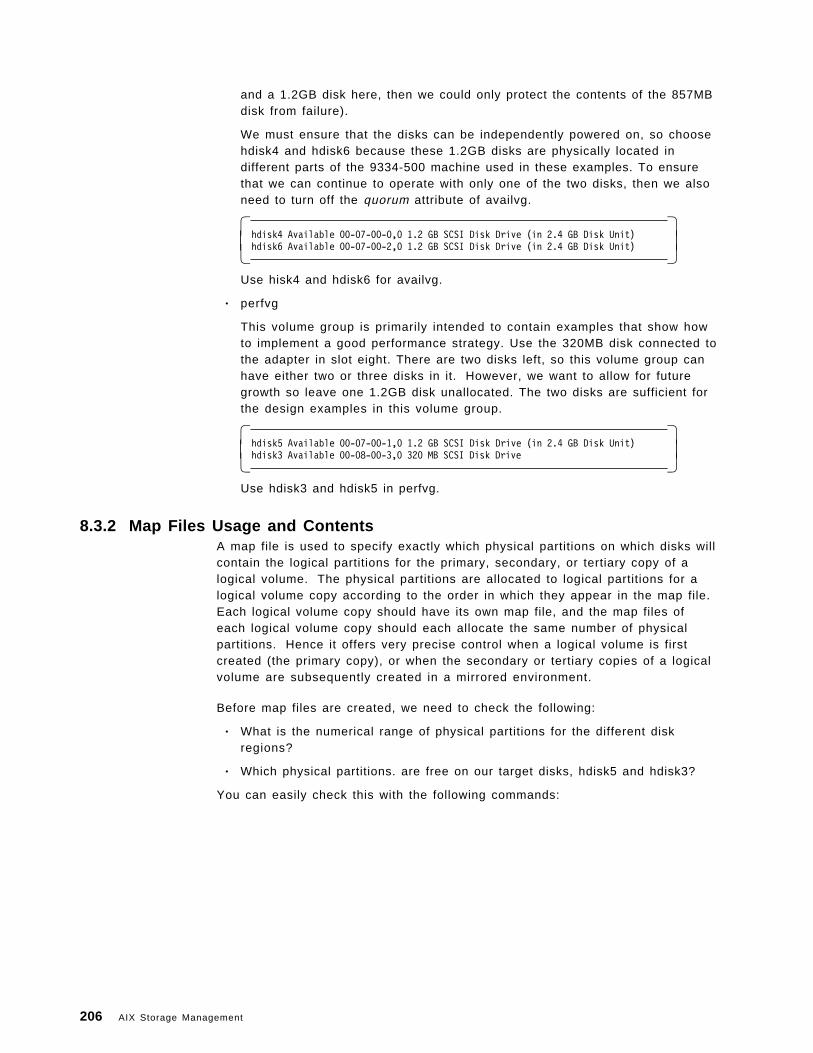
and a 1.2GB disk here, then we could only protect the contents of the 857MBdisk from failure).
We must ensure that the disks can be independently powered on, so choosehdisk4 and hdisk6 because these 1.2GB disks are physically located indifferent parts of the 9334-500 machine used in these examples. To ensurethat we can continue to operate with only one of the two disks, then we alsoneed to turn off the quorum attribute of availvg.
� �hdisk4 Available 00-07-00-0,0 1.2 GB SCSI Disk Drive (in 2.4 GB Disk Unit)hdisk6 Available 00-07-00-2,0 1.2 GB SCSI Disk Drive (in 2.4 GB Disk Unit)� �
Use hisk4 and hdisk6 for availvg.
• perfvg
This volume group is primarily intended to contain examples that show howto implement a good performance strategy. Use the 320MB disk connected tothe adapter in slot eight. There are two disks left, so this volume group canhave either two or three disks in it. However, we want to allow for futuregrowth so leave one 1.2GB disk unallocated. The two disks are sufficient forthe design examples in this volume group.
� �hdisk5 Available 00-07-00-1,0 1.2 GB SCSI Disk Drive (in 2.4 GB Disk Unit)hdisk3 Available 00-08-00-3,0 320 MB SCSI Disk Drive� �
Use hdisk3 and hdisk5 in perfvg.
8.3.2 Map Files Usage and ContentsA map file is used to specify exactly which physical partitions on which disks willcontain the logical partitions for the primary, secondary, or tertiary copy of alogical volume. The physical partitions are allocated to logical partitions for alogical volume copy according to the order in which they appear in the map file.Each logical volume copy should have its own map file, and the map files ofeach logical volume copy should each allocate the same number of physicalpartitions. Hence it offers very precise control when a logical volume is firstcreated (the primary copy), or when the secondary or tertiary copies of a logicalvolume are subsequently created in a mirrored environment.
Before map files are created, we need to check the following:
• What is the numerical range of physical partitions for the different diskregions?
• Which physical partitions. are free on our target disks, hdisk5 and hdisk3?
You can easily check this with the following commands:
206 AIX Storage Management
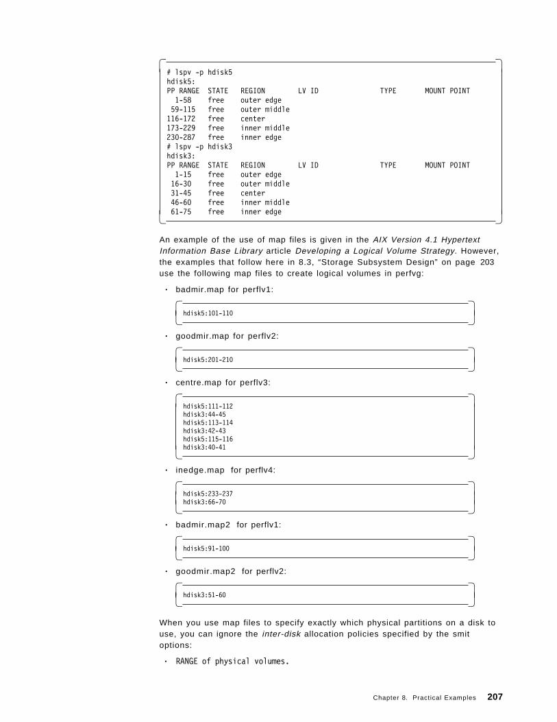
� �# lspv -p hdisk5hdisk5:PP RANGE STATE REGION LV ID TYPE MOUNT POINT1-58 free outer edge59-115 free outer middle116-172 free center173-229 free inner middle230-287 free inner edge# lspv -p hdisk3hdisk3:PP RANGE STATE REGION LV ID TYPE MOUNT POINT1-15 free outer edge16-30 free outer middle31-45 free center46-60 free inner middle61-75 free inner edge� �
An example of the use of map files is given in the AIX Version 4.1 HypertextInformation Base Library article Developing a Logical Volume Strategy. However,the examples that follow here in 8.3, “Storage Subsystem Design” on page 203use the following map files to create logical volumes in perfvg:
• badmir.map for perflv1:
� �hdisk5:101-110� �
• goodmir.map for perflv2:
� �hdisk5:201-210� �
• centre.map for perflv3:
� �hdisk5:111-112hdisk3:44-45hdisk5:113-114hdisk3:42-43hdisk5:115-116hdisk3:40-41� �
• inedge.map for perflv4:
� �hdisk5:233-237hdisk3:66-70� �
• badmir.map2 for perflv1:
� �hdisk5:91-100� �
• goodmir.map2 for perflv2:
� �hdisk3:51-60� �
When you use map files to specify exactly which physical partitions on a disk touse, you can ignore the inter-disk allocation policies specified by the smitoptions:
• RANGE of physical volumes.
Chapter 8. Practical Examples 207
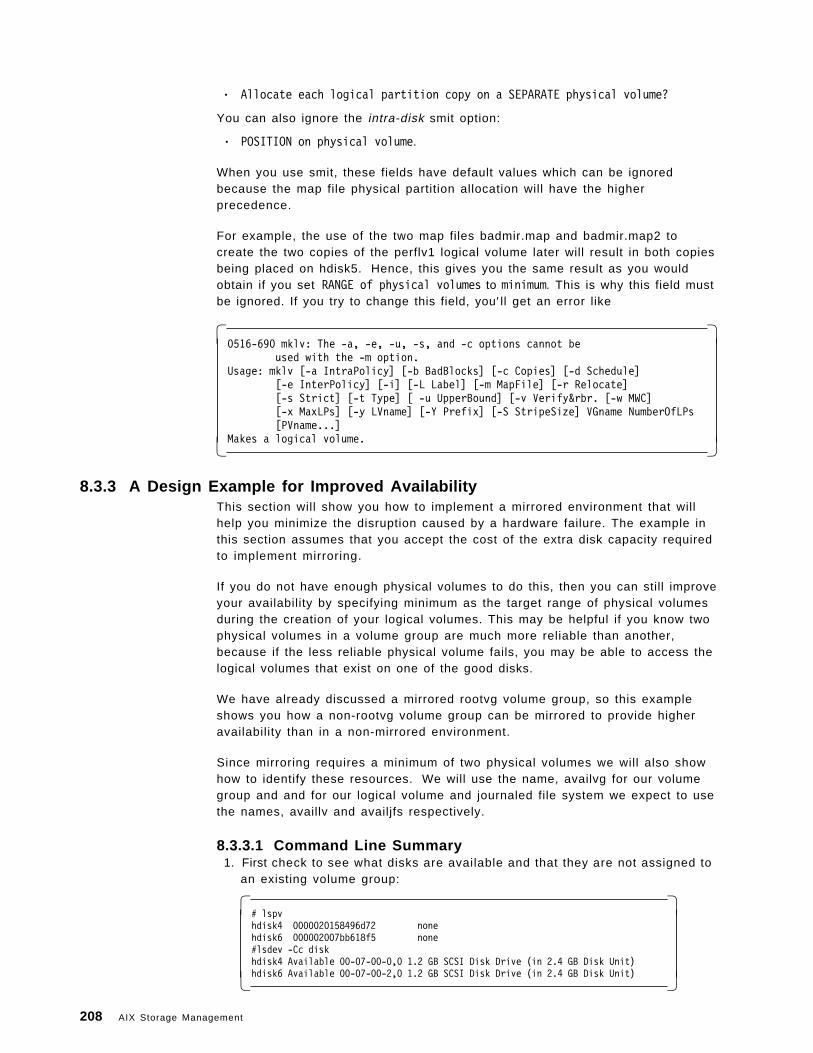
• Allocate each logical partition copy on a SEPARATE physical volume?
You can also ignore the intra-disk smit option:
• POSITION on physical volume.
When you use smit, these fields have default values which can be ignoredbecause the map file physical partition allocation will have the higherprecedence.
For example, the use of the two map files badmir.map and badmir.map2 tocreate the two copies of the perflv1 logical volume later will result in both copiesbeing placed on hdisk5. Hence, this gives you the same result as you wouldobtain if you set RANGE of physical volumes to minimum. This is why this field mustbe ignored. If you try to change this field, you′ ll get an error like
� �0516-690 mklv: The -a, -e, -u, -s, and -c options cannot be
used with the -m option.Usage: mklv [-a IntraPolicy] [-b BadBlocks] [-c Copies] [-d Schedule]
[-e InterPolicy] [-i] [-L Label] [-m MapFile] [-r Relocate][-s Strict] [-t Type] [ -u UpperBound] [-v Verify&rbr. [-w MWC][-x MaxLPs] [-y LVname] [-Y Prefix] [-S StripeSize] VGname NumberOfLPs[PVname...]
Makes a logical volume.� �
8.3.3 A Design Example for Improved AvailabilityThis section will show you how to implement a mirrored environment that willhelp you minimize the disruption caused by a hardware failure. The example inthis section assumes that you accept the cost of the extra disk capacity requiredto implement mirroring.
If you do not have enough physical volumes to do this, then you can still improveyour availability by specifying minimum as the target range of physical volumesduring the creation of your logical volumes. This may be helpful if you know twophysical volumes in a volume group are much more reliable than another,because if the less reliable physical volume fails, you may be able to access thelogical volumes that exist on one of the good disks.
We have already discussed a mirrored rootvg volume group, so this exampleshows you how a non-rootvg volume group can be mirrored to provide higheravailability than in a non-mirrored environment.
Since mirroring requires a minimum of two physical volumes we will also showhow to identify these resources. We will use the name, availvg for our volumegroup and and for our logical volume and journaled file system we expect to usethe names, availlv and availjfs respectively.
8.3.3.1 Command Line Summary 1. First check to see what disks are available and that they are not assigned to
an existing volume group:
� �# lspvhdisk4 0000020158496d72 nonehdisk6 000002007bb618f5 none#lsdev -Cc diskhdisk4 Available 00-07-00-0,0 1.2 GB SCSI Disk Drive (in 2.4 GB Disk Unit)hdisk6 Available 00-07-00-2,0 1.2 GB SCSI Disk Drive (in 2.4 GB Disk Unit)� �
208 AIX Storage Management
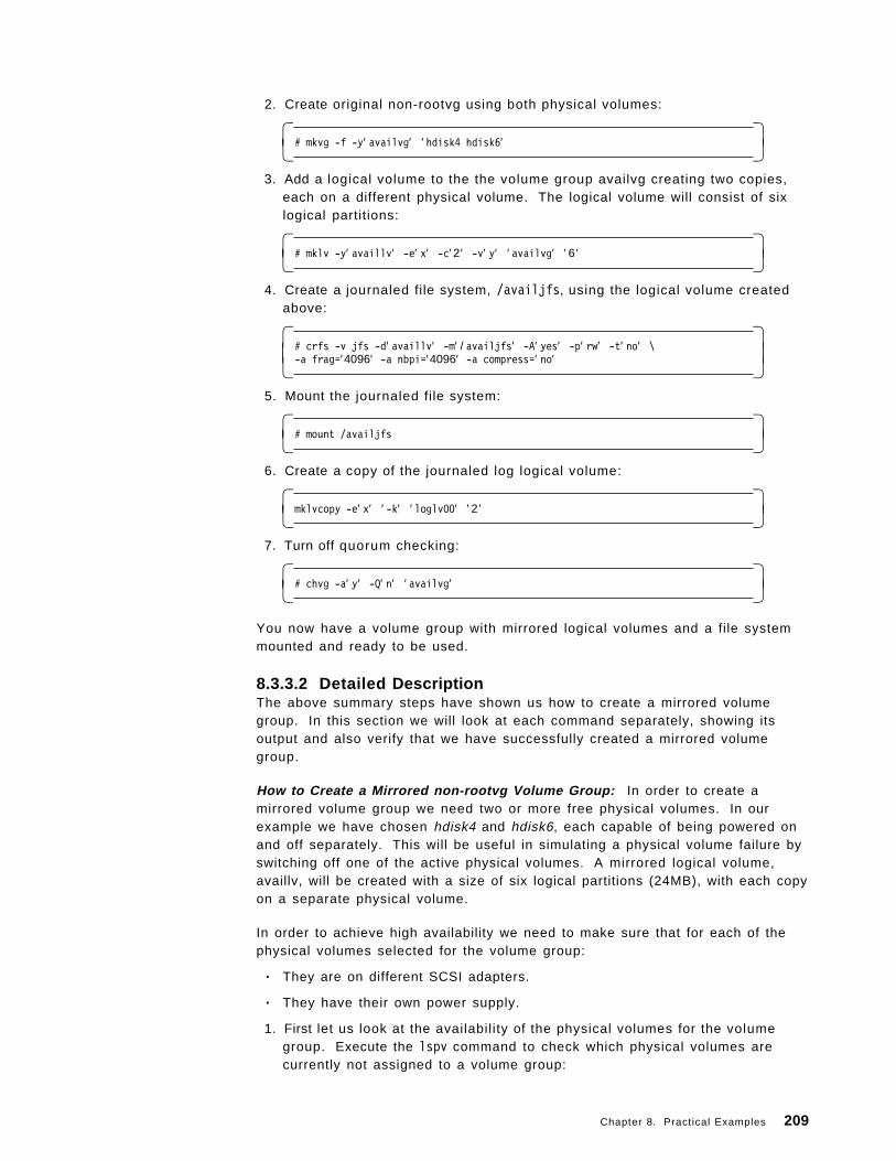
2. Create original non-rootvg using both physical volumes:
� �# mkvg -f -y′ availvg′ ′ hdisk4 hdisk6′� �
3. Add a logical volume to the the volume group availvg creating two copies,each on a different physical volume. The logical volume will consist of sixlogical partitions:
� �# mklv -y′ availlv′ -e′ x′ -c′ 2 ′ -v′ y′ ′ availvg′ ′ 6 ′� �
4. Create a journaled file system, /availjfs, using the logical volume createdabove:
� �# crfs -v jfs -d′ availlv′ -m′ / availjfs′ -A′ yes′ -p′ rw′ -t′ no′ \-a frag=′4096′ -a nbpi=′4096′ -a compress=′ no′� �
5. Mount the journaled file system:
� �# mount /availjfs� �
6. Create a copy of the journaled log logical volume:
� �mklvcopy -e′ x′ ′ -k′ ′ loglv00′ ′ 2 ′� �
7. Turn off quorum checking:
� �# chvg -a′ y′ -Q′ n′ ′ availvg′� �
You now have a volume group with mirrored logical volumes and a file systemmounted and ready to be used.
8.3.3.2 Detailed DescriptionThe above summary steps have shown us how to create a mirrored volumegroup. In this section we will look at each command separately, showing itsoutput and also verify that we have successfully created a mirrored volumegroup.
How to Create a Mirrored non-rootvg Volume Group: In order to create amirrored volume group we need two or more free physical volumes. In ourexample we have chosen hdisk4 and hdisk6, each capable of being powered onand off separately. This will be useful in simulating a physical volume failure byswitching off one of the active physical volumes. A mirrored logical volume,availlv, will be created with a size of six logical partitions (24MB), with each copyon a separate physical volume.
In order to achieve high availability we need to make sure that for each of thephysical volumes selected for the volume group:
• They are on different SCSI adapters.
• They have their own power supply.
1. First let us look at the availability of the physical volumes for the volumegroup. Execute the lspv command to check which physical volumes arecurrently not assigned to a volume group:
Chapter 8. Practical Examples 209
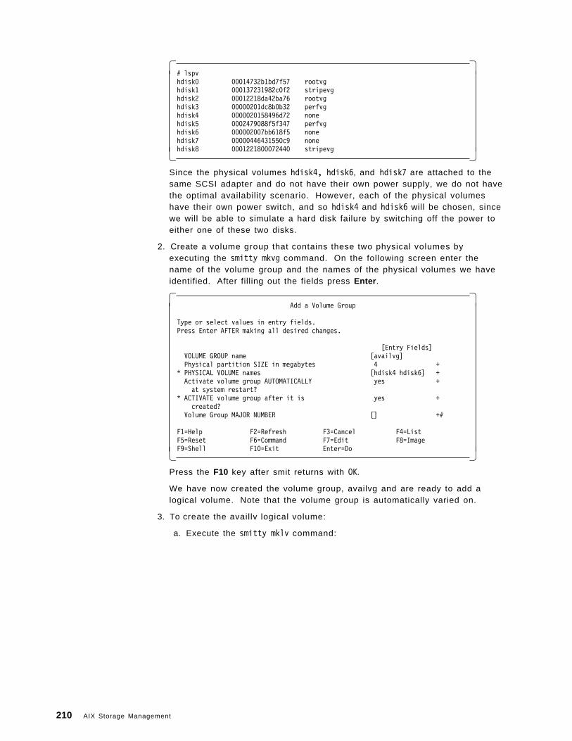
� �# lspvhdisk0 00014732b1bd7f57 rootvghdisk1 000137231982c0f2 stripevghdisk2 00012218da42ba76 rootvghdisk3 00000201dc8b0b32 perfvghdisk4 0000020158496d72 nonehdisk5 0002479088f5f347 perfvghdisk6 000002007bb618f5 nonehdisk7 00000446431550c9 nonehdisk8 0001221800072440 stripevg� �
Since the physical volumes hdisk4, hdisk6, and hdisk7 are attached to thesame SCSI adapter and do not have their own power supply, we do not havethe optimal availability scenario. However, each of the physical volumeshave their own power switch, and so hdisk4 and hdisk6 will be chosen, sincewe will be able to simulate a hard disk failure by switching off the power toeither one of these two disks.
2. Create a volume group that contains these two physical volumes byexecuting the smitty mkvg command. On the following screen enter thename of the volume group and the names of the physical volumes we haveidentified. After filling out the fields press Enter .
� �Add a Volume Group
Type or select values in entry fields.Press Enter AFTER making all desired changes.
[Entry Fields]VOLUME GROUP name [availvg]Physical partition SIZE in megabytes 4 +
* PHYSICAL VOLUME names [hdisk4 hdisk6] +Activate volume group AUTOMATICALLY yes +at system restart?
* ACTIVATE volume group after it is yes +created?
Volume Group MAJOR NUMBER [] +#
F1=Help F2=Refresh F3=Cancel F4=ListF5=Reset F6=Command F7=Edit F8=ImageF9=Shell F10=Exit Enter=Do� �
Press the F10 key after smit returns with OK.
We have now created the volume group, availvg and are ready to add alogical volume. Note that the volume group is automatically varied on.
3. To create the availlv logical volume:
a. Execute the smitty mklv command:
210 AIX Storage Management
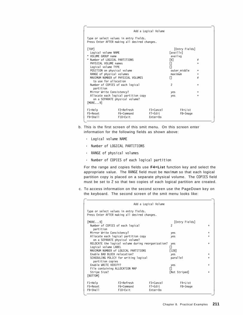
� �Add a Logical Volume
Type or select values in entry fields.Press Enter AFTER making all desired changes.
[TOP] [Entry Fields]Logical volume NAME [availlv]
* VOLUME GROUP name availvg* Number of LOGICAL PARTITIONS [6] #PHYSICAL VOLUME names [] +Logical volume TYPE []POSITION on physical volume outer_middle +RANGE of physical volumes maximum +MAXIMUM NUMBER of PHYSICAL VOLUMES [] #to use for allocation
Number of COPIES of each logical 2 +partition
Mirror Write Consistency? yes +Allocate each logical partition copy yes +on a SEPARATE physical volume?
[MORE...9]
F1=Help F2=Refresh F3=Cancel F4=ListF5=Reset F6=Command F7=Edit F8=ImageF9=Shell F10=Exit Enter=Do� �
b. This is the first screen of this smit menu. On this screen enterinformation for the following fields as shown above:
• Logical volume NAME
• Number of LOGICAL PARTITIONS
• RANGE of physical volumes
• Number of COPIES of each logical partition
For the range and copies fields use F4=List function key and select theappropriate value. The RANGE field must be maximum so that each logicalpartition copy is placed on a separate physical volume. The COPIES fieldmust be set to 2 so that two copies of each logical partition are created.
c. To access information on the second screen use the PageDown key onthe keyboard. The second screen of the smit menu looks like:
� �Add a Logical Volume
Type or select values in entry fields.Press Enter AFTER making all desired changes.
[MORE...9] [Entry Fields]Number of COPIES of each logical 2 +partition
Mirror Write Consistency? yes +Allocate each logical partition copy yes +on a SEPARATE physical volume?
RELOCATE the logical volume during reorganization? yes +Logical volume LABEL []MAXIMUM NUMBER of LOGICAL PARTITIONS [128]Enable BAD BLOCK relocation? yes +SCHEDULING POLICY for writing logical parallel +partition copies
Enable WRITE VERIFY? yes +File containing ALLOCATION MAP []Stripe Size? [Not Striped] +
[BOTTOM]
F1=Help F2=Refresh F3=Cancel F4=ListF5=Reset F6=Command F7=Edit F8=ImageF9=Shell F10=Exit Enter=Do� �
Chapter 8. Practical Examples 211
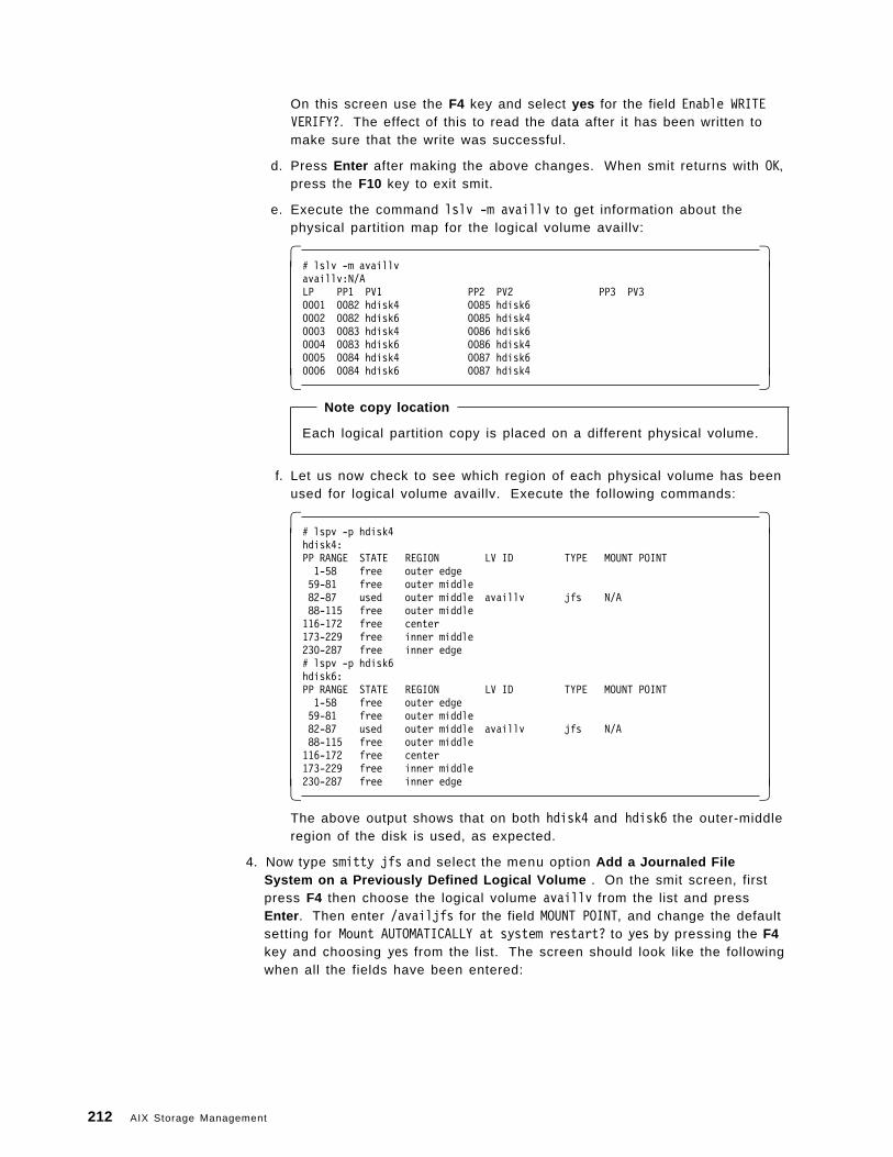
On this screen use the F4 key and select yes for the field Enable WRITEVERIFY?. The effect of this to read the data after it has been written tomake sure that the write was successful.
d. Press Enter after making the above changes. When smit returns with OK,press the F10 key to exit smit.
e. Execute the command lslv -m availlv to get information about thephysical partition map for the logical volume availlv:
� �# lslv -m availlvavaillv:N/ALP PP1 PV1 PP2 PV2 PP3 PV30001 0082 hdisk4 0085 hdisk60002 0082 hdisk6 0085 hdisk40003 0083 hdisk4 0086 hdisk60004 0083 hdisk6 0086 hdisk40005 0084 hdisk4 0087 hdisk60006 0084 hdisk6 0087 hdisk4� �
Note copy location
Each logical partition copy is placed on a different physical volume.
f. Let us now check to see which region of each physical volume has beenused for logical volume availlv. Execute the following commands:
� �# lspv -p hdisk4hdisk4:PP RANGE STATE REGION LV ID TYPE MOUNT POINT1-58 free outer edge59-81 free outer middle82-87 used outer middle availlv jfs N/A88-115 free outer middle116-172 free center173-229 free inner middle230-287 free inner edge# lspv -p hdisk6hdisk6:PP RANGE STATE REGION LV ID TYPE MOUNT POINT1-58 free outer edge59-81 free outer middle82-87 used outer middle availlv jfs N/A88-115 free outer middle116-172 free center173-229 free inner middle230-287 free inner edge� �
The above output shows that on both hdisk4 and hdisk6 the outer-middleregion of the disk is used, as expected.
4. Now type smitty jfs and select the menu option Add a Journaled FileSystem on a Previously Defined Logical Volume . On the smit screen, firstpress F4 then choose the logical volume availlv from the list and pressEnter . Then enter /availjfs for the field MOUNT POINT, and change the defaultsetting for Mount AUTOMATICALLY at system restart? to yes by pressing the F4key and choosing yes from the list. The screen should look like the followingwhen all the fields have been entered:
212 AIX Storage Management
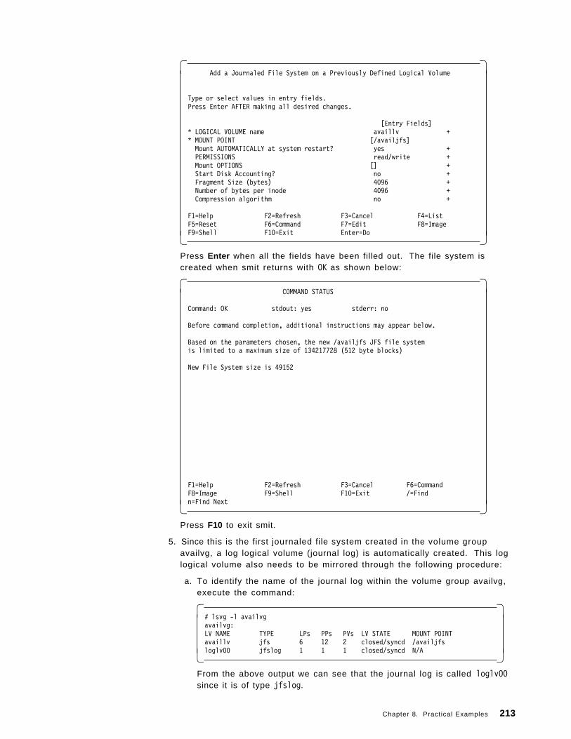
� �Add a Journaled File System on a Previously Defined Logical Volume
Type or select values in entry fields.Press Enter AFTER making all desired changes.
[Entry Fields]* LOGICAL VOLUME name availlv +* MOUNT POINT [/availjfs]Mount AUTOMATICALLY at system restart? yes +PERMISSIONS read/write +Mount OPTIONS [] +Start Disk Accounting? no +Fragment Size (bytes) 4096 +Number of bytes per inode 4096 +Compression algorithm no +
F1=Help F2=Refresh F3=Cancel F4=ListF5=Reset F6=Command F7=Edit F8=ImageF9=Shell F10=Exit Enter=Do� �
Press Enter when all the fields have been filled out. The file system iscreated when smit returns with OK as shown below:
� �COMMAND STATUS
Command: OK stdout: yes stderr: no
Before command completion, additional instructions may appear below.
Based on the parameters chosen, the new /availjfs JFS file systemis limited to a maximum size of 134217728 (512 byte blocks)
New File System size is 49152
F1=Help F2=Refresh F3=Cancel F6=CommandF8=Image F9=Shell F10=Exit /=Findn=Find Next� �
Press F10 to exit smit.
5. Since this is the first journaled file system created in the volume groupavailvg, a log logical volume (journal log) is automatically created. This loglogical volume also needs to be mirrored through the following procedure:
a. To identify the name of the journal log within the volume group availvg,execute the command:
� �# lsvg -l availvgavailvg:LV NAME TYPE LPs PPs PVs LV STATE MOUNT POINTavaillv jfs 6 12 2 closed/syncd /availjfsloglv00 jfslog 1 1 1 closed/syncd N/A� �
From the above output we can see that the journal log is called loglv00since it is of type jfslog.
Chapter 8. Practical Examples 213
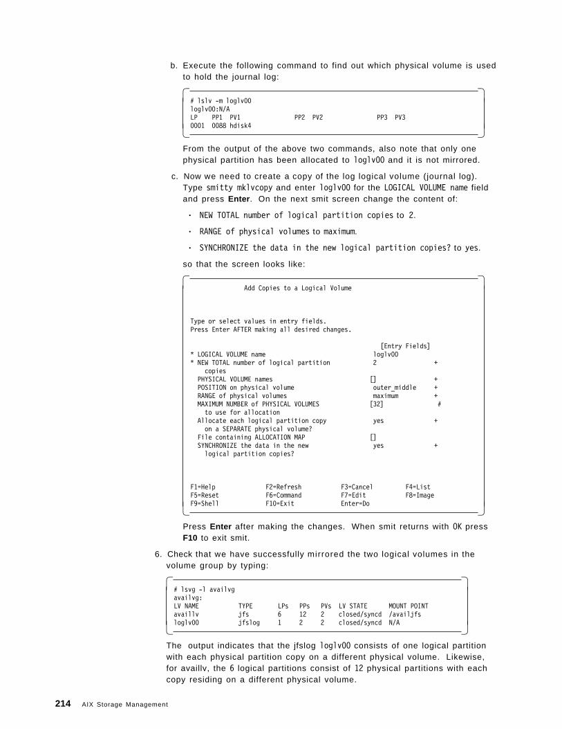
b. Execute the following command to find out which physical volume is usedto hold the journal log:
� �# lslv -m loglv00loglv00:N/ALP PP1 PV1 PP2 PV2 PP3 PV30001 0088 hdisk4� �
From the output of the above two commands, also note that only onephysical partition has been allocated to loglv00 and it is not mirrored.
c. Now we need to create a copy of the log logical volume (journal log).Type smitty mklvcopy and enter loglv00 for the LOGICAL VOLUME name fieldand press Enter . On the next smit screen change the content of:
• NEW TOTAL number of logical partition copies to 2.
• RANGE of physical volumes to maximum.
• SYNCHRONIZE the data in the new logical partition copies? to yes.
so that the screen looks like:
� �Add Copies to a Logical Volume
Type or select values in entry fields.Press Enter AFTER making all desired changes.
[Entry Fields]* LOGICAL VOLUME name loglv00* NEW TOTAL number of logical partition 2 +
copiesPHYSICAL VOLUME names [] +POSITION on physical volume outer_middle +RANGE of physical volumes maximum +MAXIMUM NUMBER of PHYSICAL VOLUMES [32] #to use for allocation
Allocate each logical partition copy yes +on a SEPARATE physical volume?
File containing ALLOCATION MAP []SYNCHRONIZE the data in the new yes +logical partition copies?
F1=Help F2=Refresh F3=Cancel F4=ListF5=Reset F6=Command F7=Edit F8=ImageF9=Shell F10=Exit Enter=Do� �
Press Enter after making the changes. When smit returns with OK pressF10 to exit smit.
6. Check that we have successfully mirrored the two logical volumes in thevolume group by typing:
� �# lsvg -l availvgavailvg:LV NAME TYPE LPs PPs PVs LV STATE MOUNT POINTavaillv jfs 6 12 2 closed/syncd /availjfsloglv00 jfslog 1 2 2 closed/syncd N/A� �
The output indicates that the jfslog loglv00 consists of one logical partitionwith each physical partition copy on a different physical volume. Likewise,for availlv, the 6 logical partitions consist of 12 physical partitions with eachcopy residing on a different physical volume.
214 AIX Storage Management
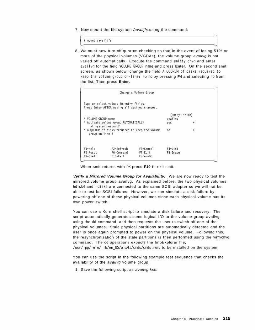
7. Now mount the file system /availjfs using the command:
� �# mount /availjfs� �
8. We must now turn off quorum checking so that in the event of losing 51% ormore of the physical volumes (VGDAs), the volume group availvg is notvaried off automatically. Execute the command smitty chvg and enteravailvg for the field VOLUME GROUP name and press Enter . On the second smitscreen, as shown below, change the field A QUORUM of disks required tokeep the volume group on-line? to no by pressing F4 and selecting no fromthe list. Then press Enter .
� �Change a Volume Group
Type or select values in entry fields.Press Enter AFTER making all desired changes.
[Entry Fields]* VOLUME GROUP name availvg* Activate volume group AUTOMATICALLY yes +
at system restart?* A QUORUM of disks required to keep the volume no +
group on-line ?
F1=Help F2=Refresh F3=Cancel F4=ListF5=Reset F6=Command F7=Edit F8=ImageF9=Shell F10=Exit Enter=Do� �
When smit returns with OK press F10 to exit smit.
Verify a Mirrored Volume Group for Availability: We are now ready to test themirrored volume group availvg. As explained before, the two physical volumeshdisk4 and hdisk6 are connected to the same SCSI adapter so we will not beable to test for SCSI failures. However, we can simulate a disk failure bypowering off one of these physical volumes since each physical volume has itsown power switch.
You can use a Korn shell script to simulate a disk failure and recovery. Thescript automatically generates some logical I/O to the volume group availvgusing the dd command and then requests the user to switch off one of thephysical volumes. Stale physical partitions are automatically detected and theuser is once again prompted to power on the physical volume. Following this,the resynchronization of the stale partitions is then performed using the varyonvgcommand. The dd operations expects the InfoExplorer file,/usr/lpp/info/lib/en_US/aix41/cmds/cmds.rom, to be installed on the system.
You can use the script in the following example test sequence that checks theavailability of the availvg volume group.
1. Save the following script as availvg.ksh.
Chapter 8. Practical Examples 215
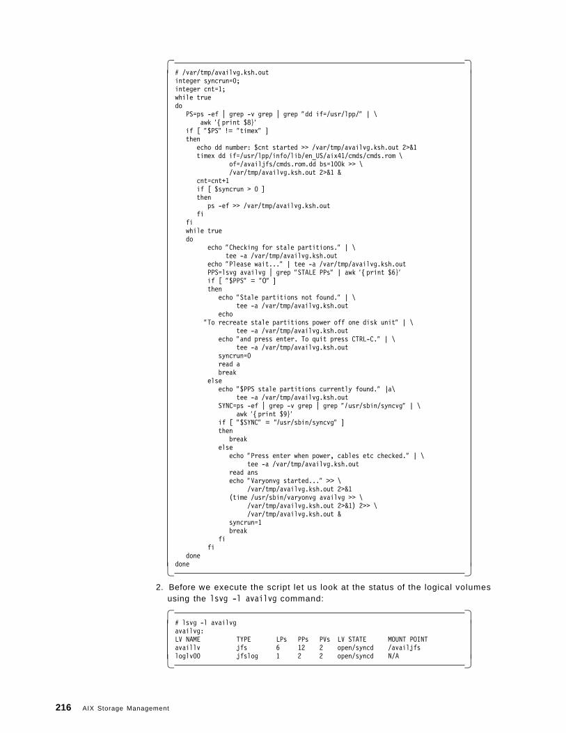
� �# /var/tmp/availvg.ksh.outinteger syncrun=0;integer cnt=1;while truedo
PS=ps -ef | grep -v grep | grep ″dd if=/usr/lpp/″ | \awk ′ {print $8}′
if [ ″$PS″ != ″timex″ ]then
echo dd number: $cnt started >> /var/tmp/availvg.ksh.out 2>&1timex dd if=/usr/lpp/info/lib/en_US/aix41/cmds/cmds.rom \
of=/availjfs/cmds.rom.dd bs=100k >> \/var/tmp/availvg.ksh.out 2>&1 &
cnt=cnt+1if [ $syncrun > 0 ]then
ps -ef >> /var/tmp/availvg.ksh.outfi
fiwhile truedo
echo ″Checking for stale partitions.″ | \tee -a /var/tmp/availvg.ksh.out
echo ″Please wait...″ | tee -a /var/tmp/availvg.ksh.outPPS=lsvg availvg | grep ″STALE PPs″ | awk ′ {print $6}′if [ ″$PPS″ = ″0″ ]then
echo ″Stale partitions not found.″ | \tee -a /var/tmp/availvg.ksh.out
echo″To recreate stale partitions power off one disk unit″ | \
tee -a /var/tmp/availvg.ksh.outecho ″and press enter. To quit press CTRL-C.″ | \
tee -a /var/tmp/availvg.ksh.outsyncrun=0read abreak
elseecho ″$PPS stale partitions currently found.″ |a\
tee -a /var/tmp/availvg.ksh.outSYNC=ps -ef | grep -v grep | grep ″ /usr/sbin/syncvg″ | \
awk ′ {print $9}′if [ ″$SYNC″ = ″/usr/sbin/syncvg″ ]then
breakelse
echo ″Press enter when power, cables etc checked.″ | \tee -a /var/tmp/availvg.ksh.out
read ansecho ″Varyonvg started...″ >> \
/var/tmp/availvg.ksh.out 2>&1(time /usr/sbin/varyonvg availvg >> \
/var/tmp/availvg.ksh.out 2>&1) 2>> \/var/tmp/availvg.ksh.out &
syncrun=1break
fifi
donedone� �
2. Before we execute the script let us look at the status of the logical volumesusing the lsvg -l availvg command:
� �# lsvg -l availvgavailvg:LV NAME TYPE LPs PPs PVs LV STATE MOUNT POINTavaillv jfs 6 12 2 open/syncd /availjfsloglv00 jfslog 1 2 2 open/syncd N/A� �
216 AIX Storage Management
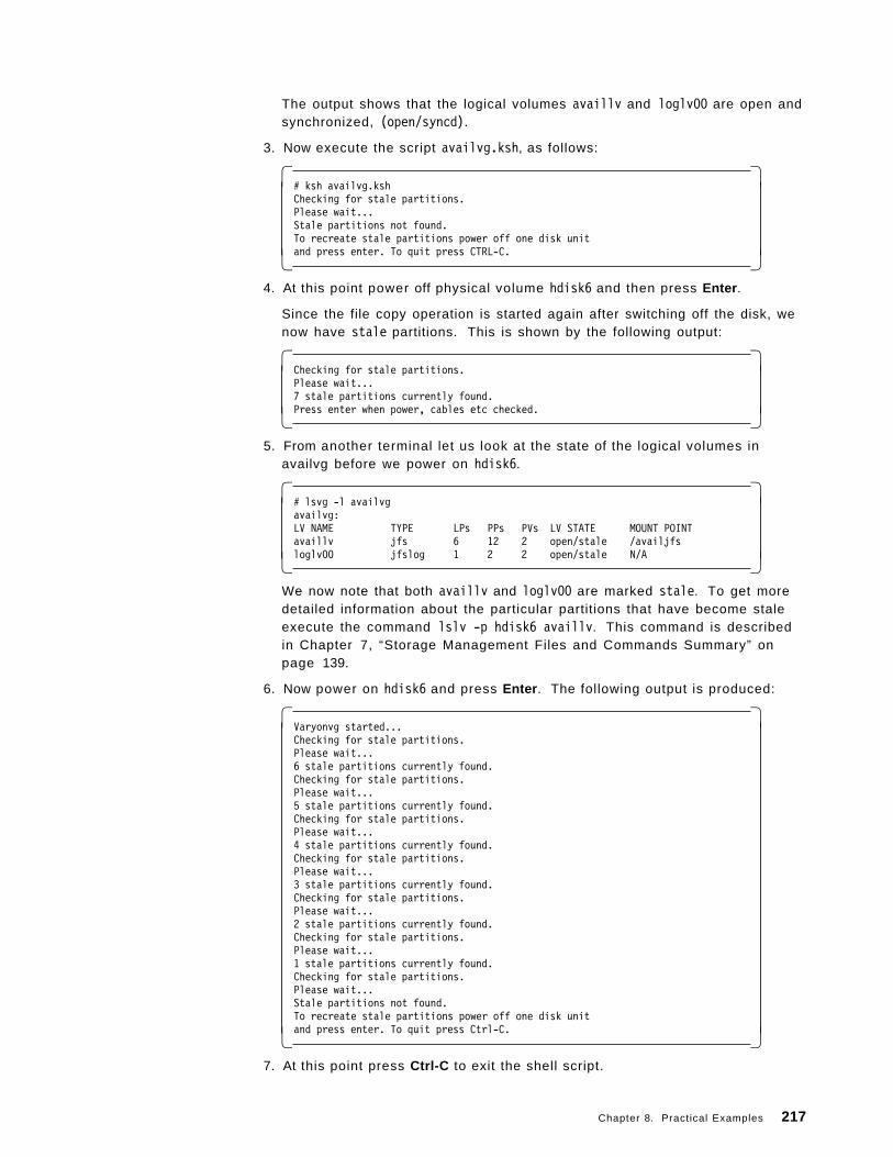
The output shows that the logical volumes availlv and loglv00 are open andsynchronized, (open/syncd).
3. Now execute the script availvg.ksh, as follows:
� �# ksh availvg.kshChecking for stale partitions.Please wait...Stale partitions not found.To recreate stale partitions power off one disk unitand press enter. To quit press CTRL-C.� �
4. At this point power off physical volume hdisk6 and then press Enter .
Since the file copy operation is started again after switching off the disk, wenow have stale partitions. This is shown by the following output:
� �Checking for stale partitions.Please wait...7 stale partitions currently found.Press enter when power, cables etc checked.� �
5. From another terminal let us look at the state of the logical volumes inavailvg before we power on hdisk6.
� �# lsvg -l availvgavailvg:LV NAME TYPE LPs PPs PVs LV STATE MOUNT POINTavaillv jfs 6 12 2 open/stale /availjfsloglv00 jfslog 1 2 2 open/stale N/A� �
We now note that both availlv and loglv00 are marked stale. To get moredetailed information about the particular partitions that have become staleexecute the command lslv -p hdisk6 availlv. This command is describedin Chapter 7, “Storage Management Files and Commands Summary” onpage 139.
6. Now power on hdisk6 and press Enter . The following output is produced:
� �Varyonvg started...Checking for stale partitions.Please wait...6 stale partitions currently found.Checking for stale partitions.Please wait...5 stale partitions currently found.Checking for stale partitions.Please wait...4 stale partitions currently found.Checking for stale partitions.Please wait...3 stale partitions currently found.Checking for stale partitions.Please wait...2 stale partitions currently found.Checking for stale partitions.Please wait...1 stale partitions currently found.Checking for stale partitions.Please wait...Stale partitions not found.To recreate stale partitions power off one disk unitand press enter. To quit press Ctrl-C.� �
7. At this point press Ctrl-C to exit the shell script.
Chapter 8. Practical Examples 217
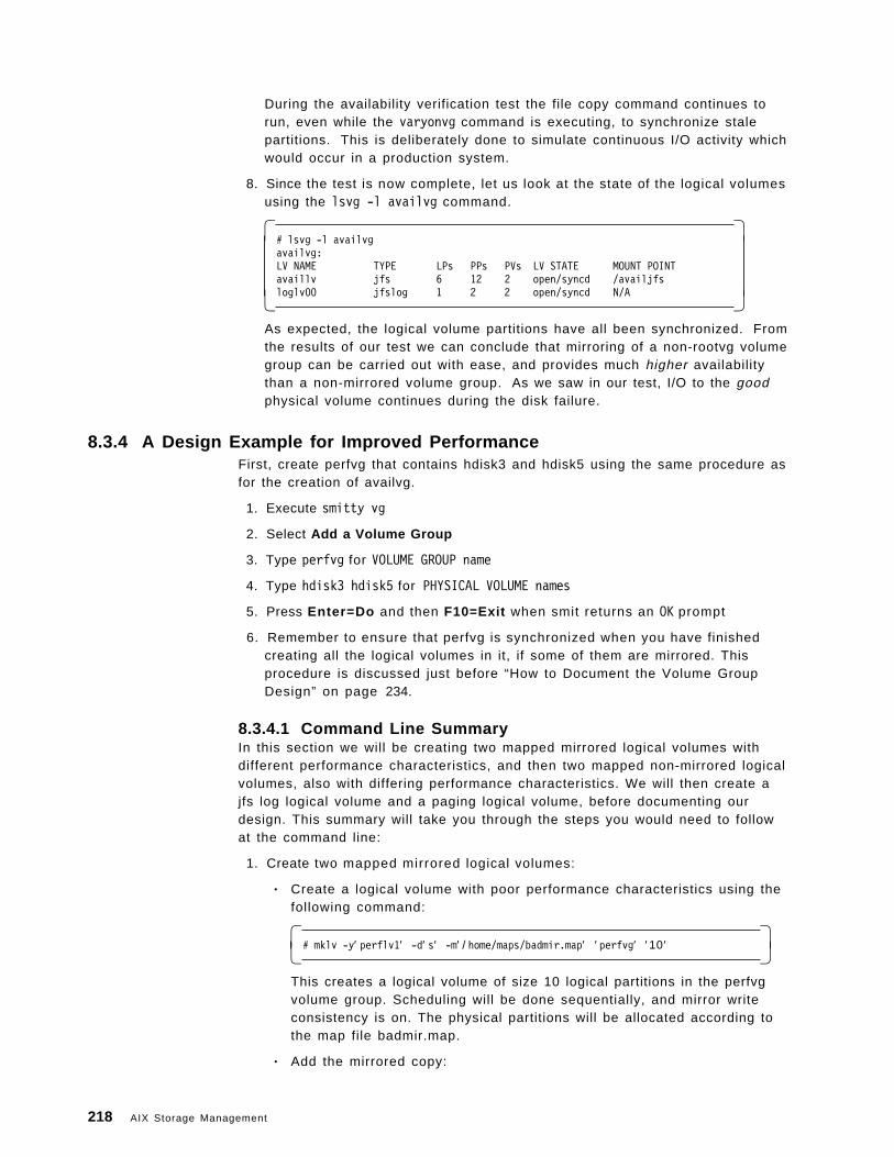
During the availability verification test the file copy command continues torun, even while the varyonvg command is executing, to synchronize stalepartitions. This is deliberately done to simulate continuous I/O activity whichwould occur in a production system.
8. Since the test is now complete, let us look at the state of the logical volumesusing the lsvg -l availvg command.
� �# lsvg -l availvgavailvg:LV NAME TYPE LPs PPs PVs LV STATE MOUNT POINTavaillv jfs 6 12 2 open/syncd /availjfsloglv00 jfslog 1 2 2 open/syncd N/A� �
As expected, the logical volume partitions have all been synchronized. Fromthe results of our test we can conclude that mirroring of a non-rootvg volumegroup can be carried out with ease, and provides much higher availabilitythan a non-mirrored volume group. As we saw in our test, I/O to the goodphysical volume continues during the disk failure.
8.3.4 A Design Example for Improved PerformanceFirst, create perfvg that contains hdisk3 and hdisk5 using the same procedure asfor the creation of availvg.
1. Execute smitty vg
2. Select Add a Volume Group
3. Type perfvg for VOLUME GROUP name
4. Type hdisk3 hdisk5 for PHYSICAL VOLUME names
5. Press Enter=Do and then F10=Exit when smit returns an OK prompt
6. Remember to ensure that perfvg is synchronized when you have finishedcreating all the logical volumes in it, if some of them are mirrored. Thisprocedure is discussed just before “How to Document the Volume GroupDesign” on page 234.
8.3.4.1 Command Line SummaryIn this section we will be creating two mapped mirrored logical volumes withdifferent performance characteristics, and then two mapped non-mirrored logicalvolumes, also with differing performance characteristics. We will then create ajfs log logical volume and a paging logical volume, before documenting ourdesign. This summary will take you through the steps you would need to followat the command line:
1. Create two mapped mirrored logical volumes:
• Create a logical volume with poor performance characteristics using thefollowing command:
� �# mklv -y′ perflv1′ -d′ s′ -m′ / home/maps/badmir.map′ ′ perfvg′ ′ 10 ′� �
This creates a logical volume of size 10 logical partitions in the perfvgvolume group. Scheduling will be done sequentially, and mirror writeconsistency is on. The physical partitions will be allocated according tothe map file badmir.map.
• Add the mirrored copy:
218 AIX Storage Management
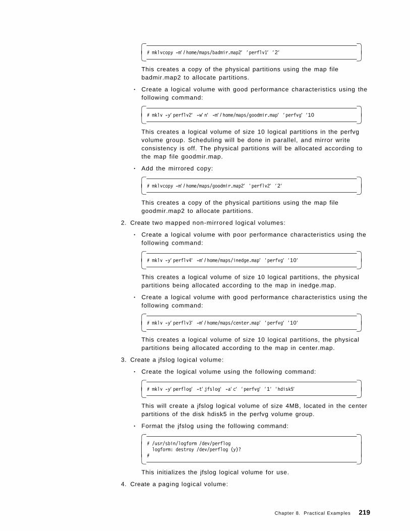
� �# mklvcopy -m′ / home/maps/badmir.map2′ ′ perflv1′ ′ 2 ′� �
This creates a copy of the physical partitions using the map filebadmir.map2 to allocate partitions.
• Create a logical volume with good performance characteristics using thefollowing command:
� �# mklv -y′ perflv2′ -w′ n′ -m′ / home/maps/goodmir.map′ ′ perfvg′ ′10� �
This creates a logical volume of size 10 logical partitions in the perfvgvolume group. Scheduling will be done in parallel, and mirror writeconsistency is off. The physical partitions will be allocated according tothe map file goodmir.map.
• Add the mirrored copy:
� �# mklvcopy -m′ / home/maps/goodmir.map2′ ′ perflv2′ ′ 2 ′� �
This creates a copy of the physical partitions using the map filegoodmir.map2 to allocate partitions.
2. Create two mapped non-mirrored logical volumes:
• Create a logical volume with poor performance characteristics using thefollowing command:
� �# mklv -y′ perflv4′ -m′ / home/maps/inedge.map′ ′ perfvg′ ′ 10 ′� �
This creates a logical volume of size 10 logical partitions, the physicalpartitions being allocated according to the map in inedge.map.
• Create a logical volume with good performance characteristics using thefollowing command:
� �# mklv -y′ perflv3′ -m′ / home/maps/center.map′ ′ perfvg′ ′ 10 ′� �
This creates a logical volume of size 10 logical partitions, the physicalpartitions being allocated according to the map in center.map.
3. Create a jfslog logical volume:
• Create the logical volume using the following command:
� �# mklv -y′ perflog′ -t′ jfslog′ -a′ c′ ′ perfvg′ ′ 1 ′ ′hdisk5′� �
This will create a jfslog logical volume of size 4MB, located in the centerpartitions of the disk hdisk5 in the perfvg volume group.
• Format the jfslog using the following command:
� �# /usr/sbin/logform /dev/perfloglogform: destroy /dev/perflog (y)?
#� �This initializes the jfslog logical volume for use.
4. Create a paging logical volume:
Chapter 8. Practical Examples 219
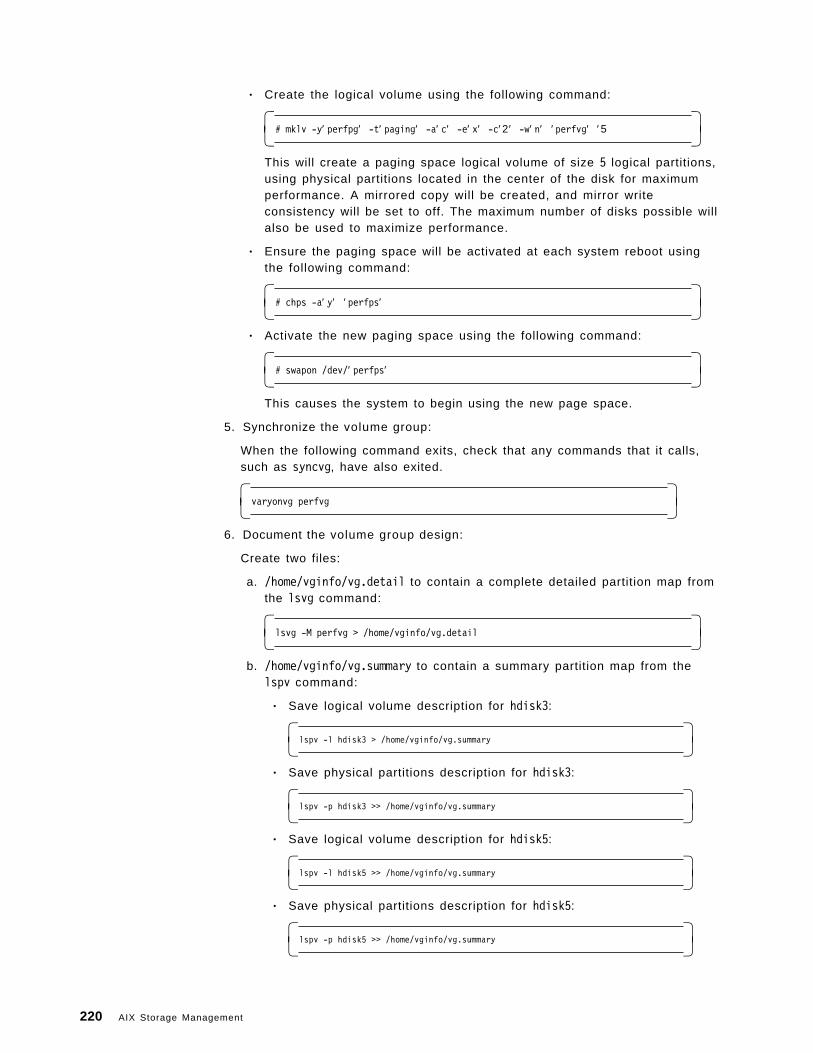
• Create the logical volume using the following command:
� �# mklv -y′ perfpg′ -t′ paging′ -a′ c′ -e′ x′ -c′ 2 ′ -w′ n′ ′ perfvg′ ′ 5� �
This will create a paging space logical volume of size 5 logical partitions,using physical partitions located in the center of the disk for maximumperformance. A mirrored copy will be created, and mirror writeconsistency will be set to off. The maximum number of disks possible willalso be used to maximize performance.
• Ensure the paging space will be activated at each system reboot usingthe following command:
� �# chps -a′ y′ ′ perfps′� �
• Activate the new paging space using the following command:
� �# swapon /dev/′ perfps′� �
This causes the system to begin using the new page space.
5. Synchronize the volume group:
When the following command exits, check that any commands that it calls,such as syncvg, have also exited.
� �varyonvg perfvg� �
6. Document the volume group design:
Create two files:
a. /home/vginfo/vg.detail to contain a complete detailed partition map fromthe lsvg command:
� �lsvg -M perfvg > /home/vginfo/vg.detail� �
b. /home/vginfo/vg.summary to contain a summary partition map from thelspv command:
• Save logical volume description for hdisk3:
� �lspv -l hdisk3 > /home/vginfo/vg.summary� �• Save physical partitions description for hdisk3:
� �lspv -p hdisk3 >> /home/vginfo/vg.summary� �• Save logical volume description for hdisk5:
� �lspv -l hdisk5 >> /home/vginfo/vg.summary� �• Save physical partitions description for hdisk5:
� �lspv -p hdisk5 >> /home/vginfo/vg.summary� �
220 AIX Storage Management
c. Refer to “An Example Description of a Volume Group Design” onpage 237 for the output files we obtained.
The performance characteristics of this volume group will be investigated in thedetailed guidance section that follows.
8.3.4.2 Detailed GuidanceThis section will now look at these processes in detail:
How to Create Two Mirrored Logical Volumes: This section shows how tocreate two logical volumes which have different attribute settings for thoseattributes that significantly affect performance in a mirrored environment. Thedifferent attributes, described by their smit field name, are:
• Mirror Write Consistency?
• SCHEDULING POLICY for writing logical partition copies
• Enable WRITE VERIFY?
• File containing ALLOCATION MAP
The main difference in the maps is that the good mirrored logical volumeuses a second disk for its copy, but the bad mirrored logical volume uses thesame disk for its primary and secondary copy.
The two logical volumes are:
• perflv1 - the bad mirrored logical volume
• perflv2 - the good mirrored logical volume
Warning - Choose attributes carefully
It is very important to note that when the above attributes are set to giveoptimal performance, the availability of the good mirror perflv2 suffers.Hence, this choice between performance and availability is a good exampleof the design decisions that you will have to make.
Let′s create two mirrored logical volumes; one whose attributes should givegood performance, and one whose attributes should give bad performance.Start by creating only the primary copy so that allocation maps can be used.
If you want to avoid map files
Please refer to “How to Create a Paging Type Logical Volume” on page 231for an example of how to create a mirrored logical volume (two copies) withoptimal performance attributes, that does not use a physical partitionallocation map file.
The good logical volume, perflv2, will use goodmir.map, and the bad logicalvolume, perflv1, will use badmir.map. These map files were displayed earlier in8.3, “Storage Subsystem Design” on page 203.
For the bad mirror:
1. Type smitty lv.
2. Select Add a Logical Volume .
Chapter 8. Practical Examples 221
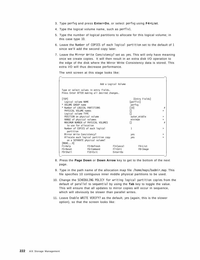
3. Type perfvg and press Enter=Do , or select perfvg using F4=List .
4. Type the logical volume name, such as perflv1.
5. Type the number of logical partitions to allocate for this logical volume; inthis case type 10.
6. Leave the Number of COPIES of each logical partition set to the default of 1since we′ ll add the second copy later.
7. Leave the Mirror Write Consistency? set as yes. This wil l only have meaningonce we create copies. It will then result in an extra disk I/O operation tothe edge of the disk where the Mirror Write Consistency data is stored. Thisextra I/O will thus decrease performance.
The smit screen at this stage looks like:
� �Add a Logical Volume
Type or select values in entry fields.Press Enter AFTER making all desired changes.
[TOP] [Entry Fields]Logical volume NAME [perflv1]
* VOLUME GROUP name perfvg* Number of LOGICAL PARTITIONS [10] #PHYSICAL VOLUME names [] +Logical volume TYPE []POSITION on physical volume outer_middle +RANGE of physical volumes minimum +MAXIMUM NUMBER of PHYSICAL VOLUMES [] #to use for allocation
Number of COPIES of each logical 1 +partition
Mirror Write Consistency? yes +Allocate each logical partition copy yes +on a SEPARATE physical volume?
[MORE...9]F1=Help F2=Refresh F3=Cancel F4=ListF5=Reset F6=Command F7=Edit F8=ImageF9=Shell F10=Exit Enter=Do� �
8. Press the Page Down or Down Arrow key to get to the bottom of the nextpage.
9. Type in the path name of the allocation map file /home/maps/badmir.map. Thisfile specifies 10 contiguous inner middle physical partitions to be used.
10. Change the SCHEDULING POLICY for writing logical partition copies from thedefault of parallel to sequential by using the Tab key to toggle the value.This will ensure that all updates to mirror copies will occur in sequence,which will obviously be slower than parallel writes.
11. Leave Enable WRITE VERIFY? as the default, yes (again, this is the sloweroption), so that the screen looks like:
222 AIX Storage Management
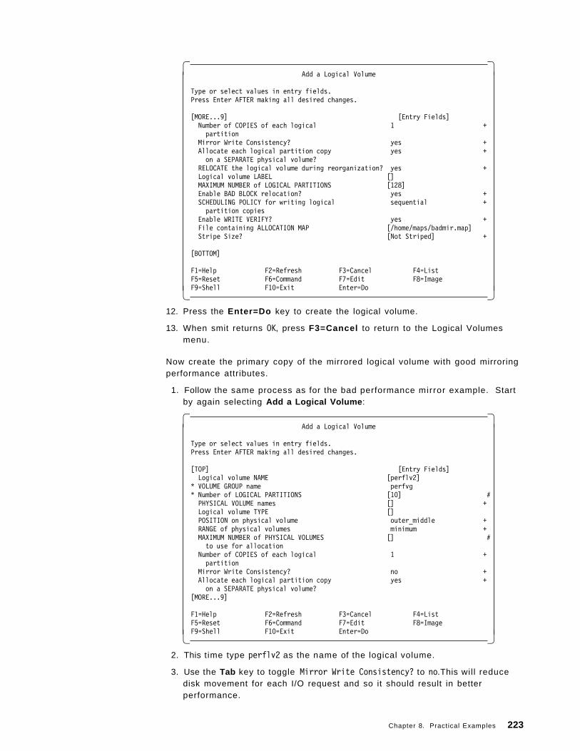
� �Add a Logical Volume
Type or select values in entry fields.Press Enter AFTER making all desired changes.
[MORE...9] [Entry Fields]Number of COPIES of each logical 1 +partition
Mirror Write Consistency? yes +Allocate each logical partition copy yes +on a SEPARATE physical volume?
RELOCATE the logical volume during reorganization? yes +Logical volume LABEL []MAXIMUM NUMBER of LOGICAL PARTITIONS [128]Enable BAD BLOCK relocation? yes +SCHEDULING POLICY for writing logical sequential +partition copies
Enable WRITE VERIFY? yes +File containing ALLOCATION MAP [/home/maps/badmir.map]Stripe Size? [Not Striped] +
[BOTTOM]
F1=Help F2=Refresh F3=Cancel F4=ListF5=Reset F6=Command F7=Edit F8=ImageF9=Shell F10=Exit Enter=Do� �
12. Press the Enter=Do key to create the logical volume.
13. When smit returns OK, press F3=Cancel to return to the Logical Volumesmenu.
Now create the primary copy of the mirrored logical volume with good mirroringperformance attributes.
1. Follow the same process as for the bad performance mirror example. Startby again selecting Add a Logical Volume :
� �Add a Logical Volume
Type or select values in entry fields.Press Enter AFTER making all desired changes.
[TOP] [Entry Fields]Logical volume NAME [perflv2]
* VOLUME GROUP name perfvg* Number of LOGICAL PARTITIONS [10] #PHYSICAL VOLUME names [] +Logical volume TYPE []POSITION on physical volume outer_middle +RANGE of physical volumes minimum +MAXIMUM NUMBER of PHYSICAL VOLUMES [] #to use for allocation
Number of COPIES of each logical 1 +partition
Mirror Write Consistency? no +Allocate each logical partition copy yes +on a SEPARATE physical volume?
[MORE...9]
F1=Help F2=Refresh F3=Cancel F4=ListF5=Reset F6=Command F7=Edit F8=ImageF9=Shell F10=Exit Enter=Do� �
2. This time type perflv2 as the name of the logical volume.
3. Use the Tab key to toggle Mirror Write Consistency? to no.This wil l reducedisk movement for each I/O request and so it should result in betterperformance.
Chapter 8. Practical Examples 223
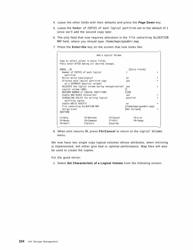
4. Leave the other fields with their defaults and press the Page Down key.
5. Leave the Number of COPIES of each logical partition set to the default of 1since we′ ll add the second copy later.
6. The only field that now requires alteration is the File containing ALLOCATIONMAP field, where you should type /home/maps/goodmir.map.
7. Press the Enter=Do key on the screen that now looks like:
� �Add a Logical Volume
Type or select values in entry fields.Press Enter AFTER making all desired changes.
[MORE...9] [Entry Fields]Number of COPIES of each logical 1 +partition
Mirror Write Consistency? no +Allocate each logical partition copy yes +on a SEPARATE physical volume?
RELOCATE the logical volume during reorganization? yes +Logical volume LABEL []MAXIMUM NUMBER of LOGICAL PARTITIONS [128]Enable BAD BLOCK relocation? yes +SCHEDULING POLICY for writing logical parallel +partition copies
Enable WRITE VERIFY? no +File containing ALLOCATION MAP [/home/maps/goodmir.map]Stripe Size? [Not Striped] +
[BOTTOM]
F1=Help F2=Refresh F3=Cancel F4=ListF5=Reset F6=Command F7=Edit F8=ImageF9=Shell F10=Exit Enter=Do� �
8. When smit returns OK, press F3=Cancel to return to the Logical Volumesmenu.
We now have two single copy logical volumes whose attributes, when mirroringis implemented, will either give bad or optimal performance. Map files will alsobe used to create the copies.
For the good mirror:
1. Select Set Characteristic of a Logical Volume from the following screen:
224 AIX Storage Management
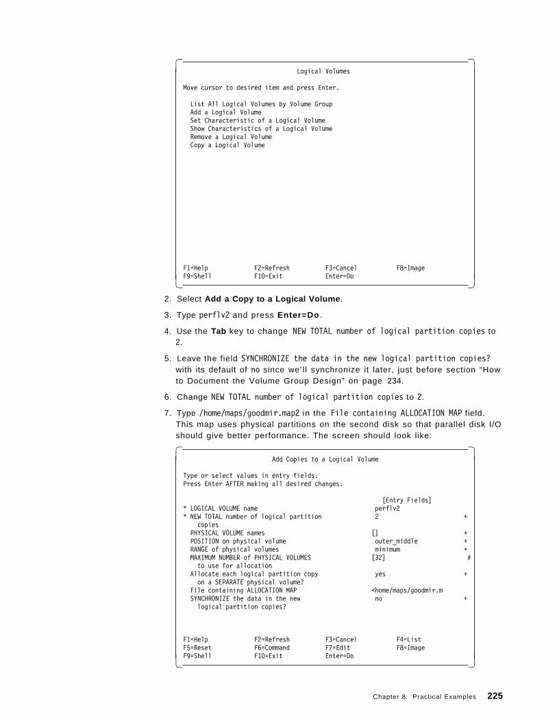
� �Logical Volumes
Move cursor to desired item and press Enter.
List All Logical Volumes by Volume GroupAdd a Logical VolumeSet Characteristic of a Logical VolumeShow Characteristics of a Logical VolumeRemove a Logical VolumeCopy a Logical Volume
F1=Help F2=Refresh F3=Cancel F8=ImageF9=Shell F10=Exit Enter=Do� �
2. Select Add a Copy to a Logical Volume .
3. Type perflv2 and press Enter=Do .
4. Use the Tab key to change NEW TOTAL number of logical partition copies to2.
5. Leave the field SYNCHRONIZE the data in the new logical partition copies?with its default of no since we′ ll synchronize it later, just before section “Howto Document the Volume Group Design” on page 234.
6. Change NEW TOTAL number of logical partition copies to 2.
7. Type /home/maps/goodmir.map2 in the File containing ALLOCATION MAP field.This map uses physical partitions on the second disk so that parallel disk I/Oshould give better performance. The screen should look like:
� �Add Copies to a Logical Volume
Type or select values in entry fields.Press Enter AFTER making all desired changes.
[Entry Fields]* LOGICAL VOLUME name perflv2* NEW TOTAL number of logical partition 2 +
copiesPHYSICAL VOLUME names [] +POSITION on physical volume outer_middle +RANGE of physical volumes minimum +MAXIMUM NUMBER of PHYSICAL VOLUMES [32] #to use for allocation
Allocate each logical partition copy yes +on a SEPARATE physical volume?
File containing ALLOCATION MAP <home/maps/goodmir.mSYNCHRONIZE the data in the new no +logical partition copies?
F1=Help F2=Refresh F3=Cancel F4=ListF5=Reset F6=Command F7=Edit F8=ImageF9=Shell F10=Exit Enter=Do� �
Chapter 8. Practical Examples 225
8. Press the Enter=Do key to create the logical volume copy.
9. When smit returns OK, press F3=Cancel to return to the Set Characteristicof a Logical Volume menu.
Now create the bad mirror copy:
1. Select Add a Copy to a Logical Volume .
2. Type perflv1 and press Enter=Do .
3. Use the Tab key to change NEW TOTAL number of logical partition copies to2.
4. Leave the field SYNCHRONIZE the data in the new logical partition copies?with its default of no since we′ ll synchronize it later, just before section “Howto Document the Volume Group Design” on page 234.
5. Type /home/maps/badmir.map2 in the File containing ALLOCATION MAP field. Thismap uses physical partitions on the same disk as the primary copy so that,along with the sequential disk I/O, we should get the worst performance.
6. Press the Enter=Do key to create the logical volume copy.
7. When smit returns OK, press F10=Exit to return to the command prompt.
How to Create Two Mapped Non-mirrored Logical Volumes: This section showshow to create two logical volumes which have different logical partition locationson hdisk3 and hdisk5. This enables us to investigate:
• How the Intra-Physical Volume Allocation Policy, described by smit asPOSITION on physical volume, affects performance in a non-mirroredenvironment.
• How to use a physical partition map; in smit, use File containing ALLOCATIONMAP, to get precise control of logical partition location.
The two logical volumes are:
• perflv3 - uses good disk regions according to centre.map.
• perflv4 - uses bad regions according to inedge.map.
Warning - Choose carefully
It is very important to note that when the above attributes are set to giveoptimal performance, the availability of a logical volume, even when it is notmirrored, and thus exists as only a single copy, may suffer. For example, ifyour map file uses all disks in a volume group, or if the Inter-Physical VolumeAllocation Policy is set to maximum, then although the extra disk heads mayreduce data access time, access to a logical volume may become difficult orimpossible if any disk fails.
We could have also degraded performance but improved the reliability of adisk write operation by changing Enable WRITE VERIFY? from its no defaultvalue to yes This attribute is not investigated in this example.
Let′s create both perflv3 and perflv4 using the map files that you can createusing your favorite editor, such as the vi text editor.
226 AIX Storage Management
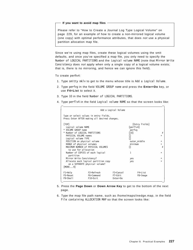
If you want to avoid map files
Please refer to “How to Create a Journal Log Type Logical Volume” onpage 229, for an example of how to create a non-mirrored logical volume(one copy) with optimal performance attributes, that does not use a physicalpartition allocation map file.
Since we′re using map files, create these logical volumes using the smitdefaults, and once you′ve specified a map file, you only need to specify theNumber of LOGICAL PARTITIONS and the Logical volume NAME (note that Mirror WriteConsistency does not apply when only a single copy of a logical volume exists;that is, there is no mirroring, and hence we can ignore this field).
To create perflv4:
1. Type smitty mklv to get to the menu whose title is Add a Logical Volume.
2. Type perfvg in the field VOLUME GROUP name and press the Enter=Do key, oruse F4=List to select it.
3. Type 10 in the field Number of LOGICAL PARTITIONS.
4. Type perflv4 in the field Logical volume NAME so that the screen looks like:
� �Add a Logical Volume
Type or select values in entry fields.Press Enter AFTER making all desired changes.
[TOP] [Entry Fields]Logical volume NAME [perflv4]
* VOLUME GROUP name perfvg* Number of LOGICAL PARTITIONS [10] #PHYSICAL VOLUME names [] +Logical volume TYPE []POSITION on physical volume outer_middle +RANGE of physical volumes minimum +MAXIMUM NUMBER of PHYSICAL VOLUMES [] #to use for allocation
Number of COPIES of each logical 1 +partition
Mirror Write Consistency? yes +Allocate each logical partition copy yes +on a SEPARATE physical volume?
[MORE...9]
F1=Help F2=Refresh F3=Cancel F4=ListF5=Reset F6=Command F7=Edit F8=ImageF9=Shell F10=Exit Enter=Do� �
5. Press the Page Down or Down Arrow Key to get to the bottom of the nextpage.
6. Type the map file path name, such as /home/maps/inedge.map, in the fieldFile containing ALLOCATION MAP so that the screen looks like:
Chapter 8. Practical Examples 227
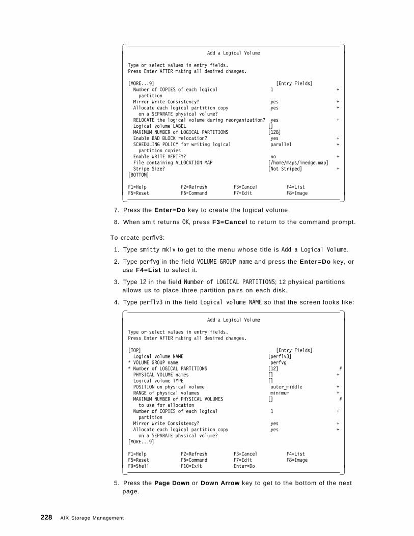
� �Add a Logical Volume
Type or select values in entry fields.Press Enter AFTER making all desired changes.
[MORE...9] [Entry Fields]Number of COPIES of each logical 1 +partition
Mirror Write Consistency? yes +Allocate each logical partition copy yes +on a SEPARATE physical volume?
RELOCATE the logical volume during reorganization? yes +Logical volume LABEL []MAXIMUM NUMBER of LOGICAL PARTITIONS [128]Enable BAD BLOCK relocation? yes +SCHEDULING POLICY for writing logical parallel +partition copies
Enable WRITE VERIFY? no +File containing ALLOCATION MAP [/home/maps/inedge.map]Stripe Size? [Not Striped] +
[BOTTOM]
F1=Help F2=Refresh F3=Cancel F4=ListF5=Reset F6=Command F7=Edit F8=Image� �
7. Press the Enter=Do key to create the logical volume.
8. When smit returns OK, press F3=Cancel to return to the command prompt.
To create perflv3:
1. Type smitty mklv to get to the menu whose title is Add a Logical Volume.
2. Type perfvg in the field VOLUME GROUP name and press the Enter=Do key, oruse F4=List to select it.
3. Type 12 in the field Number of LOGICAL PARTITIONS; 12 physical partitionsallows us to place three partition pairs on each disk.
4. Type perflv3 in the field Logical volume NAME so that the screen looks like:
� �Add a Logical Volume
Type or select values in entry fields.Press Enter AFTER making all desired changes.
[TOP] [Entry Fields]Logical volume NAME [perflv3]
* VOLUME GROUP name perfvg* Number of LOGICAL PARTITIONS [12] #PHYSICAL VOLUME names [] +Logical volume TYPE []POSITION on physical volume outer_middle +RANGE of physical volumes minimum +MAXIMUM NUMBER of PHYSICAL VOLUMES [] #to use for allocation
Number of COPIES of each logical 1 +partition
Mirror Write Consistency? yes +Allocate each logical partition copy yes +on a SEPARATE physical volume?
[MORE...9]
F1=Help F2=Refresh F3=Cancel F4=ListF5=Reset F6=Command F7=Edit F8=ImageF9=Shell F10=Exit Enter=Do� �
5. Press the Page Down or Down Arrow key to get to the bottom of the nextpage.
228 AIX Storage Management
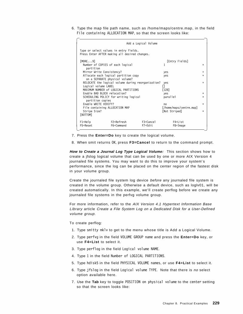
6. Type the map file path name, such as /home/maps/centre.map, in the fieldFile containing ALLOCATION MAP, so that the screen looks like:
� �Add a Logical Volume
Type or select values in entry fields.Press Enter AFTER making all desired changes.
[MORE...9] [Entry Fields]Number of COPIES of each logical 1 +partition
Mirror Write Consistency? yes +Allocate each logical partition copy yes +on a SEPARATE physical volume?
RELOCATE the logical volume during reorganization? yes +Logical volume LABEL []MAXIMUM NUMBER of LOGICAL PARTITIONS [128]Enable BAD BLOCK relocation? yes +SCHEDULING POLICY for writing logical parallel +partition copies
Enable WRITE VERIFY? no +File containing ALLOCATION MAP [/home/maps/centre.map]Stripe Size? [Not Striped] +
[BOTTOM]
F1=Help F2=Refresh F3=Cancel F4=ListF5=Reset F6=Command F7=Edit F8=Image� �
7. Press the Enter=Do key to create the logical volume.
8. When smit returns OK, press F3=Cancel to return to the command prompt.
How to Create a Journal Log Type Logical Volume: This section shows how tocreate a jfslog logical volume that can be used by one or more AIX Version 4journaled file systems. You may want to do this to improve your system′sperformance, since the log can be placed on the center region of the fastest diskin your volume group.
Create the journaled file system log device before any journaled file system iscreated in the volume group. Otherwise a default device, such as loglv01, will becreated automatically. In this example, we′ ll create perflog before we create anyjournaled file systems in the perfvg volume group.
For more information, refer to the AIX Version 4.1 Hypertext Information BaseLibrary article Create a File System Log on a Dedicated Disk for a User-Definedvolume group.
To create perflog:
1. Type smitty mklv to get to the menu whose title is Add a Logical Volume.
2. Type perfvg in the field VOLUME GROUP name and press the Enter=Do key, oruse F4=List to select it.
3. Type perflog in the field Logical volume NAME.
4. Type 1 in the field Number of LOGICAL PARTITIONS.
5. Type hdisk5 in the field PHYSICAL VOLUME names, or use F4=List to select it.
6. Type jfslog in the field Logical volume TYPE. Note that there is no selectoption available here.
7. Use the Tab key to toggle POSITION on physical volume to the center settingso that the screen looks like:
Chapter 8. Practical Examples 229
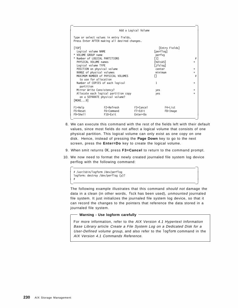
� �Add a Logical Volume
Type or select values in entry fields.Press Enter AFTER making all desired changes.
[TOP] [Entry Fields]Logical volume NAME [perflog]
* VOLUME GROUP name perfvg* Number of LOGICAL PARTITIONS [1] #PHYSICAL VOLUME names [hdisk5] +Logical volume TYPE [jfslog]POSITION on physical volume center +RANGE of physical volumes minimum +MAXIMUM NUMBER of PHYSICAL VOLUMES [] #to use for allocation
Number of COPIES of each logical 1 +partition
Mirror Write Consistency? yes +Allocate each logical partition copy yes +on a SEPARATE physical volume?
[MORE...9]
F1=Help F2=Refresh F3=Cancel F4=ListF5=Reset F6=Command F7=Edit F8=ImageF9=Shell F10=Exit Enter=Do� �
8. We can execute this command with the rest of the fields left with their defaultvalues, since most fields do not affect a logical volume that consists of onephysical partition. This logical volume can only exist as one copy on onedisk. Hence, instead of pressing the Page Down key to go to the nextscreen, press the Enter=Do key to create the logical volume.
9. When smit returns OK, press F3=Cancel to return to the command prompt.
10. We now need to format the newly created journaled file system log deviceperflog with the following command:
� �# /usr/sbin/logform /dev/perfloglogform: destroy /dev/perflog (y)?#� �
The following example illustrates that this command should not damage thedata in a clean (in other words, fsck has been used), unmounted journaledfile system. It just initializes the journaled file system log device, so that itcan record the changes to the pointers that reference the data stored in ajournaled file system.
Warning - Use logform carefully
For more information, refer to the AIX Version 4.1 Hypertext InformationBase Library article Create a File System Log on a Dedicated Disk for aUser-Defined volume group, and also refer to the logform command in theAIX Version 4.1 Commands Reference.
230 AIX Storage Management
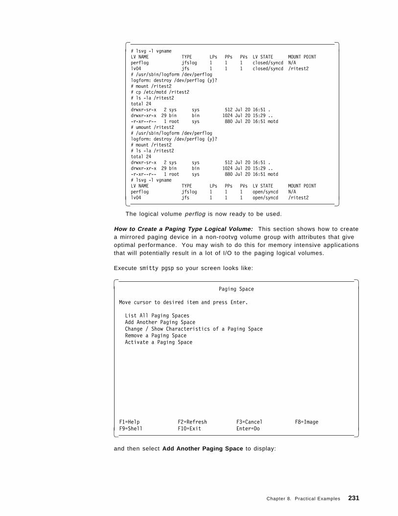
� �# lsvg -l vgnameLV NAME TYPE LPs PPs PVs LV STATE MOUNT POINTperflog jfslog 1 1 1 closed/syncd N/Alv04 jfs 1 1 1 closed/syncd /ritest2# /usr/sbin/logform /dev/perfloglogform: destroy /dev/perflog (y)?# mount /ritest2# cp /etc/motd /ritest2# ls -la /ritest2total 24drwxr-sr-x 2 sys sys 512 Jul 20 16:51 .drwxr-xr-x 29 bin bin 1024 Jul 20 15:29 ..-r-xr--r-- 1 root sys 880 Jul 20 16:51 motd# umount /ritest2# /usr/sbin/logform /dev/perfloglogform: destroy /dev/perflog (y)?# mount /ritest2# ls -la /ritest2total 24drwxr-sr-x 2 sys sys 512 Jul 20 16:51 .drwxr-xr-x 29 bin bin 1024 Jul 20 15:29 ..-r-xr--r-- 1 root sys 880 Jul 20 16:51 motd# lsvg -l vgnameLV NAME TYPE LPs PPs PVs LV STATE MOUNT POINTperflog jfslog 1 1 1 open/syncd N/Alv04 jfs 1 1 1 open/syncd /ritest2� �
The logical volume perflog is now ready to be used.
How to Create a Paging Type Logical Volume: This section shows how to createa mirrored paging device in a non-rootvg volume group with attributes that giveoptimal performance. You may wish to do this for memory intensive applicationsthat will potentially result in a lot of I/O to the paging logical volumes.
Execute smitty pgsp so your screen looks like:
� �Paging Space
Move cursor to desired item and press Enter.
List All Paging SpacesAdd Another Paging SpaceChange / Show Characteristics of a Paging SpaceRemove a Paging SpaceActivate a Paging Space
F1=Help F2=Refresh F3=Cancel F8=ImageF9=Shell F10=Exit Enter=Do� �
and then select Add Another Paging Space to display:
Chapter 8. Practical Examples 231
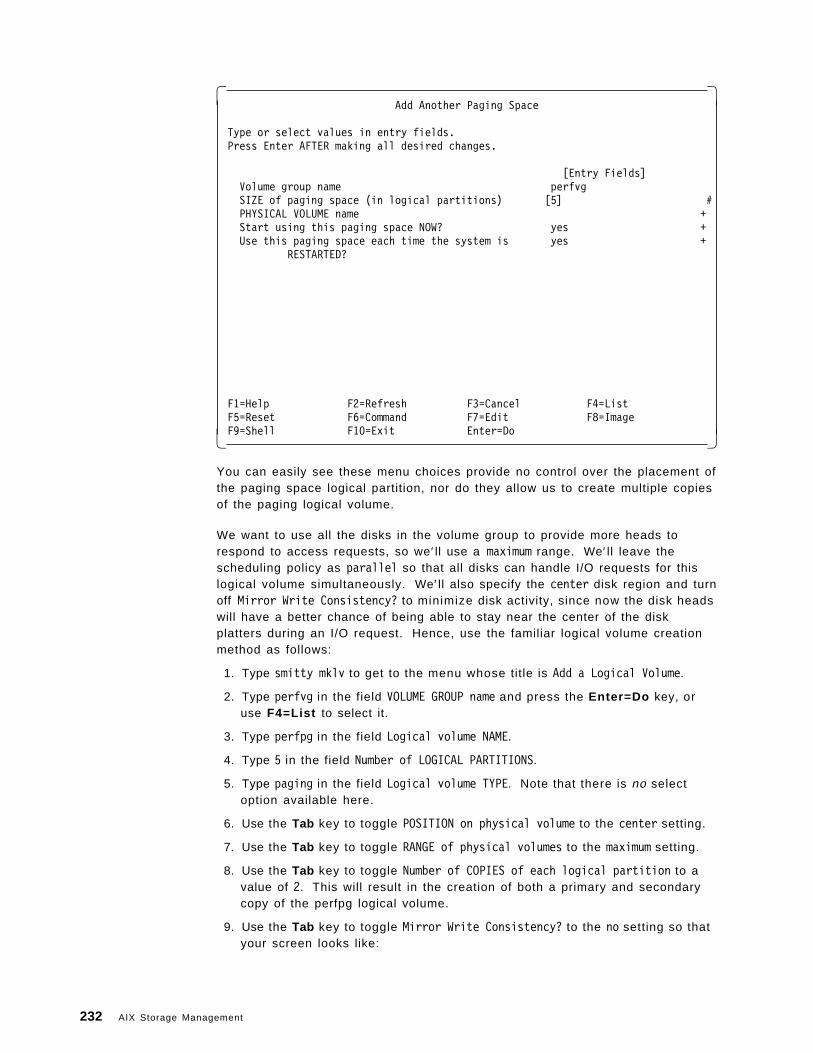
� �Add Another Paging Space
Type or select values in entry fields.Press Enter AFTER making all desired changes.
[Entry Fields]Volume group name perfvgSIZE of paging space (in logical partitions) [5] #PHYSICAL VOLUME name +Start using this paging space NOW? yes +Use this paging space each time the system is yes +
RESTARTED?
F1=Help F2=Refresh F3=Cancel F4=ListF5=Reset F6=Command F7=Edit F8=ImageF9=Shell F10=Exit Enter=Do� �
You can easily see these menu choices provide no control over the placement ofthe paging space logical partition, nor do they allow us to create multiple copiesof the paging logical volume.
We want to use all the disks in the volume group to provide more heads torespond to access requests, so we′ ll use a maximum range. We′ ll leave thescheduling policy as parallel so that all disks can handle I/O requests for thislogical volume simultaneously. We′ ll also specify the center disk region and turnoff Mirror Write Consistency? to minimize disk activity, since now the disk headswill have a better chance of being able to stay near the center of the diskplatters during an I/O request. Hence, use the familiar logical volume creationmethod as follows:
1. Type smitty mklv to get to the menu whose title is Add a Logical Volume.
2. Type perfvg in the field VOLUME GROUP name and press the Enter=Do key, oruse F4=List to select it.
3. Type perfpg in the field Logical volume NAME.
4. Type 5 in the field Number of LOGICAL PARTITIONS.
5. Type paging in the field Logical volume TYPE. Note that there is no selectoption available here.
6. Use the Tab key to toggle POSITION on physical volume to the center setting.
7. Use the Tab key to toggle RANGE of physical volumes to the maximum setting.
8. Use the Tab key to toggle Number of COPIES of each logical partition to avalue of 2. This will result in the creation of both a primary and secondarycopy of the perfpg logical volume.
9. Use the Tab key to toggle Mirror Write Consistency? to the no setting so thatyour screen looks like:
232 AIX Storage Management
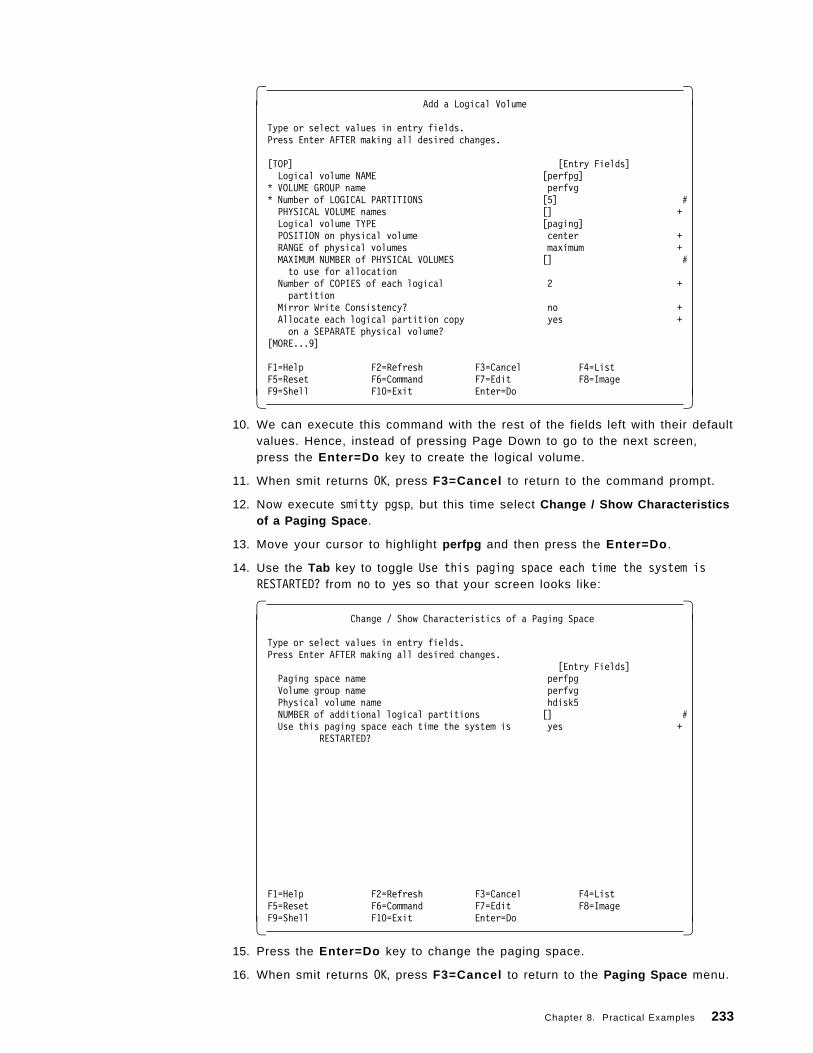
� �Add a Logical Volume
Type or select values in entry fields.Press Enter AFTER making all desired changes.
[TOP] [Entry Fields]Logical volume NAME [perfpg]
* VOLUME GROUP name perfvg* Number of LOGICAL PARTITIONS [5] #PHYSICAL VOLUME names [] +Logical volume TYPE [paging]POSITION on physical volume center +RANGE of physical volumes maximum +MAXIMUM NUMBER of PHYSICAL VOLUMES [] #to use for allocation
Number of COPIES of each logical 2 +partition
Mirror Write Consistency? no +Allocate each logical partition copy yes +on a SEPARATE physical volume?
[MORE...9]
F1=Help F2=Refresh F3=Cancel F4=ListF5=Reset F6=Command F7=Edit F8=ImageF9=Shell F10=Exit Enter=Do� �
10. We can execute this command with the rest of the fields left with their defaultvalues. Hence, instead of pressing Page Down to go to the next screen,press the Enter=Do key to create the logical volume.
11. When smit returns OK, press F3=Cancel to return to the command prompt.
12. Now execute smitty pgsp, but this time select Change / Show Characteristicsof a Paging Space .
13. Move your cursor to highlight perfpg and then press the Enter=Do .
14. Use the Tab key to toggle Use this paging space each time the system isRESTARTED? from no to yes so that your screen looks like:
� �Change / Show Characteristics of a Paging Space
Type or select values in entry fields.Press Enter AFTER making all desired changes.
[Entry Fields]Paging space name perfpgVolume group name perfvgPhysical volume name hdisk5NUMBER of additional logical partitions [] #Use this paging space each time the system is yes +
RESTARTED?
F1=Help F2=Refresh F3=Cancel F4=ListF5=Reset F6=Command F7=Edit F8=ImageF9=Shell F10=Exit Enter=Do� �
15. Press the Enter=Do key to change the paging space.
16. When smit returns OK, press F3=Cancel to return to the Paging Space menu.
Chapter 8. Practical Examples 233
17. To immediately start to use the new paging device, you can now:
• Reboot AIX Version 4 using the shutdown -Fr command, or:
a. Select Activate a Paging Space .
b. Use the F4=List key to select perfpg .
c. Press the Enter=Do key to activate the perfpg logical volume.
d. When smit returns OK, press F10=Exit to return to the commandprompt.
Synchronize the Volume Group: The final step that we need to do is tosynchronize perfvg. The parts of this step, similar to that described in “How toSynchronize rootvg” on page 195, are:
1. Execute the command smitty vg.
2. Select Activate a Volume Group .
3. Type perfvg or use F4=List to select it.
4. Press the Enter=Do key.
5. Press F10=Exit when smit returns an OK prompt.
If we have to create copies of many small logical volumes, it is more efficient forthe systems administrator to use one command after hours to synchronize them.This means that the configuration work can be done during normal businesshours without any significant I/O burdens to normal operations.
How to Document the Volume Group Design: Now that we′ve created perfvg, wecan choose some of the commands discussed in Chapter 7, “StorageManagement Files and Commands Summary” on page 139 to enable us to:
• Check that all logical volumes have been created correctly.
• Record the configuration in our system logbook for reference should we haveto manually recreate perfvg (of course, you should have multiple, testedvolume group backup images stored safely. This is discussed in 8.4,“Managing Backup and Restore” on page 244).
If you refer to the Chapter 7, “Storage Management Files and CommandsSummary” on page 139 chapter, you can see that the commands:
• lsvg
• lspv
• lslv
are quite simple since they only have a few flags. Hence we prefer to executethese commands directly from the command line rather than through the smitinterface. Therefore, although the following is a brief summary of how to use thecorrect smit options, you may prefer to follow the simple method outlined in theprevious command summary to enable you to document your volume groupconfiguration.
You should also note that the most comprehensive volume group command,lsvg -M vgname, does not have a smit interface and hence must be executed fromthe command line. It can also produce a long output for a large volume groupwith many physical volumes in it. A smaller summarized version of its outputcan be obtained by using the lspv command for each disk in the volume group,
234 AIX Storage Management
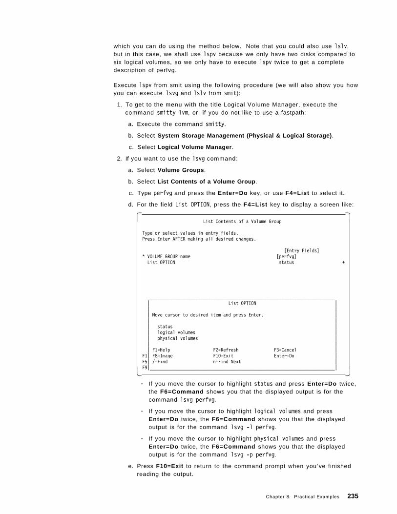
which you can do using the method below. Note that you could also use lslv,but in this case, we shall use lspv because we only have two disks compared tosix logical volumes, so we only have to execute lspv twice to get a completedescription of perfvg.
Execute lspv from smit using the following procedure (we will also show you howyou can execute lsvg and lslv from smit):
1. To get to the menu with the title Logical Volume Manager, execute thecommand smitty lvm, or, if you do not like to use a fastpath:
a. Execute the command smitty.
b. Select System Storage Management (Physical & Logical Storage) .
c. Select Logical Volume Manager .
2. If you want to use the lsvg command:
a. Select Volume Groups .
b. Select List Contents of a Volume Group .
c. Type perfvg and press the Enter=Do key, or use F4=List to select it.
d. For the field List OPTION, press the F4=List key to display a screen like:
� �List Contents of a Volume Group
Type or select values in entry fields.Press Enter AFTER making all desired changes.
[Entry Fields]* VOLUME GROUP name [perfvg]List OPTION status +
__________________________________________________________________________| List OPTION || || Move cursor to desired item and press Enter. || || status || logical volumes || physical volumes || || F1=Help F2=Refresh F3=Cancel |
F1| F8=Image F10=Exit Enter=Do |F5| /=Find n=Find Next |F9|_________________________________________________________________________|� �• If you move the cursor to highlight status and press Enter=Do twice,
the F6=Command shows you that the displayed output is for thecommand lsvg perfvg.
• If you move the cursor to highlight logical volumes and pressEnter=Do twice, the F6=Command shows you that the displayedoutput is for the command lsvg -l perfvg.
• If you move the cursor to highlight physical volumes and pressEnter=Do twice, the F6=Command shows you that the displayedoutput is for the command lsvg -p perfvg.
e. Press F10=Exit to return to the command prompt when you′ve finishedreading the output.
Chapter 8. Practical Examples 235
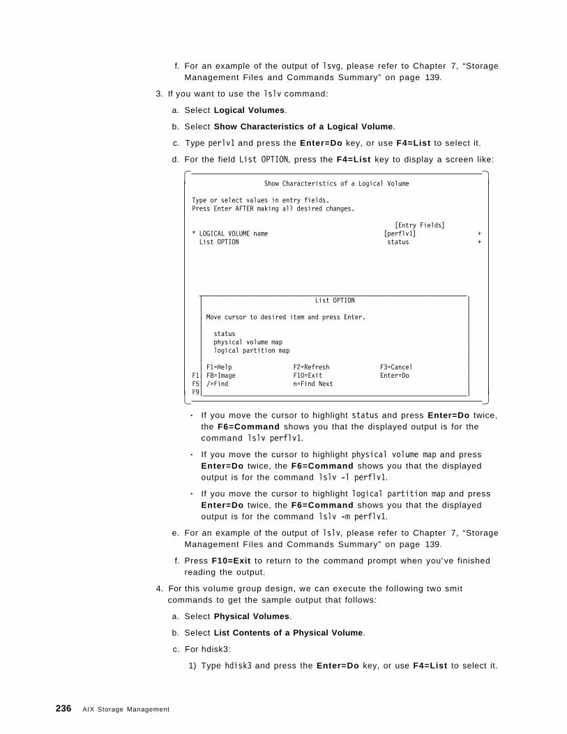
f. For an example of the output of lsvg, please refer to Chapter 7, “StorageManagement Files and Commands Summary” on page 139.
3. If you want to use the lslv command:
a. Select Logical Volumes .
b. Select Show Characteristics of a Logical Volume .
c. Type perlv1 and press the Enter=Do key, or use F4=List to select it.
d. For the field List OPTION, press the F4=List key to display a screen like:
� �Show Characteristics of a Logical Volume
Type or select values in entry fields.Press Enter AFTER making all desired changes.
[Entry Fields]* LOGICAL VOLUME name [perflv1] +List OPTION status +
__________________________________________________________________________| List OPTION || || Move cursor to desired item and press Enter. || || status || physical volume map || logical partition map || || F1=Help F2=Refresh F3=Cancel |
F1| F8=Image F10=Exit Enter=Do |F5| /=Find n=Find Next |F9|_________________________________________________________________________|� �• If you move the cursor to highlight status and press Enter=Do twice,
the F6=Command shows you that the displayed output is for thecommand lslv perflv1.
• If you move the cursor to highlight physical volume map and pressEnter=Do twice, the F6=Command shows you that the displayedoutput is for the command lslv -l perflv1.
• If you move the cursor to highlight logical partition map and pressEnter=Do twice, the F6=Command shows you that the displayedoutput is for the command lslv -m perflv1.
e. For an example of the output of lslv, please refer to Chapter 7, “StorageManagement Files and Commands Summary” on page 139.
f. Press F10=Exit to return to the command prompt when you′ve finishedreading the output.
4. For this volume group design, we can execute the following two smitcommands to get the sample output that follows:
a. Select Physical Volumes .
b. Select List Contents of a Physical Volume .
c. For hdisk3:
1) Type hdisk3 and press the Enter=Do key, or use F4=List to select it.
236 AIX Storage Management
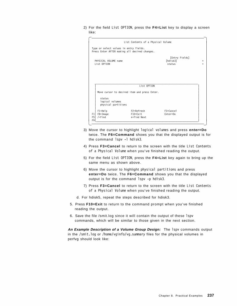
2) For the field List OPTION, press the F4=List key to display a screenlike:
� �List Contents of a Physical Volume
Type or select values in entry fields.Press Enter AFTER making all desired changes.
[Entry Fields]PHYSICAL VOLUME name [hdisk3] +List OPTION status +
__________________________________________________________________________| List OPTION || || Move cursor to desired item and press Enter. || || status || logical volumes || physical partitions || || F1=Help F2=Refresh F3=Cancel |
F1| F8=Image F10=Exit Enter=Do |F5| /=Find n=Find Next |F9|_________________________________________________________________________|� �
3) Move the cursor to highlight logical volumes and press enter=Dotwice. The F6=Command shows you that the displayed output is forthe command lspv -l hdisk3.
4) Press F3=Cancel to return to the screen with the title List Contentsof a Physical Volume when you′ve finished reading the output.
5) For the field List OPTION, press the F4=List key again to bring up thesame menu as shown above.
6) Move the cursor to highlight physical partitions and pressenter=Do twice. The F6=Command shows you that the displayedoutput is for the command lspv -p hdisk3.
7) Press F3=Cancel to return to the screen with the title List Contentsof a Physical Volume when you′ve finished reading the output.
d. For hdisk5, repeat the steps described for hdisk3.
5. Press F10=Exit to return to the command prompt when you′ve finishedreading the output.
6. Save the file /smit.log since it wil l contain the output of these lspvcommands, which will be similar to those given in the next section.
An Example Description of a Volume Group Design: The lspv commands outputin the /smit.log or /home/vginfo/vg.summary files for the physical volumes inperfvg should look like:
Chapter 8. Practical Examples 237
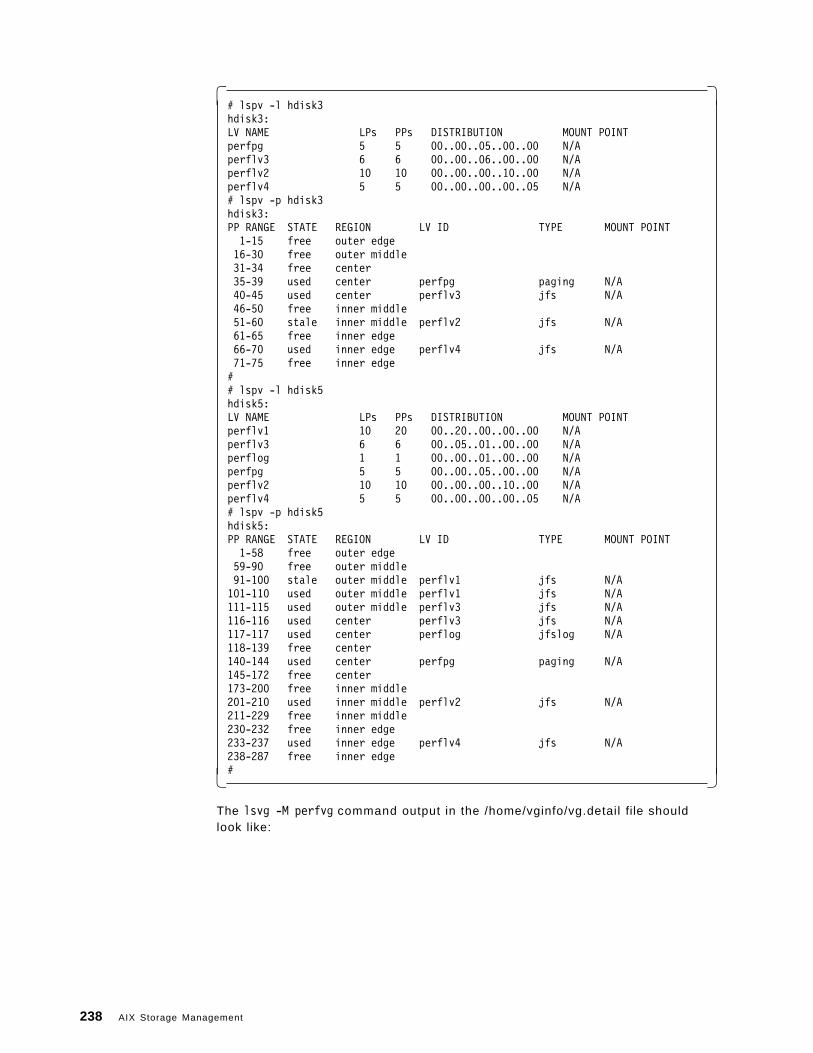
� �# lspv -l hdisk3hdisk3:LV NAME LPs PPs DISTRIBUTION MOUNT POINTperfpg 5 5 00..00..05..00..00 N/Aperflv3 6 6 00..00..06..00..00 N/Aperflv2 10 10 00..00..00..10..00 N/Aperflv4 5 5 00..00..00..00..05 N/A# lspv -p hdisk3hdisk3:PP RANGE STATE REGION LV ID TYPE MOUNT POINT1-15 free outer edge16-30 free outer middle31-34 free center35-39 used center perfpg paging N/A40-45 used center perflv3 jfs N/A46-50 free inner middle51-60 stale inner middle perflv2 jfs N/A61-65 free inner edge66-70 used inner edge perflv4 jfs N/A71-75 free inner edge## lspv -l hdisk5hdisk5:LV NAME LPs PPs DISTRIBUTION MOUNT POINTperflv1 10 20 00..20..00..00..00 N/Aperflv3 6 6 00..05..01..00..00 N/Aperflog 1 1 00..00..01..00..00 N/Aperfpg 5 5 00..00..05..00..00 N/Aperflv2 10 10 00..00..00..10..00 N/Aperflv4 5 5 00..00..00..00..05 N/A# lspv -p hdisk5hdisk5:PP RANGE STATE REGION LV ID TYPE MOUNT POINT1-58 free outer edge59-90 free outer middle91-100 stale outer middle perflv1 jfs N/A101-110 used outer middle perflv1 jfs N/A111-115 used outer middle perflv3 jfs N/A116-116 used center perflv3 jfs N/A117-117 used center perflog jfslog N/A118-139 free center140-144 used center perfpg paging N/A145-172 free center173-200 free inner middle201-210 used inner middle perflv2 jfs N/A211-229 free inner middle230-232 free inner edge233-237 used inner edge perflv4 jfs N/A238-287 free inner edge#� �
The lsvg -M perfvg command output in the /home/vginfo/vg.detail file shouldlook like:
238 AIX Storage Management
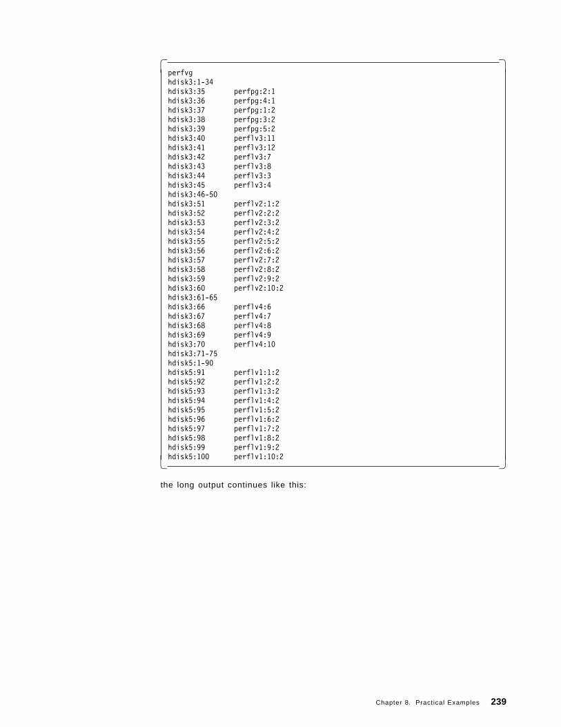
� �perfvghdisk3:1-34hdisk3:35 perfpg:2:1hdisk3:36 perfpg:4:1hdisk3:37 perfpg:1:2hdisk3:38 perfpg:3:2hdisk3:39 perfpg:5:2hdisk3:40 perflv3:11hdisk3:41 perflv3:12hdisk3:42 perflv3:7hdisk3:43 perflv3:8hdisk3:44 perflv3:3hdisk3:45 perflv3:4hdisk3:46-50hdisk3:51 perflv2:1:2hdisk3:52 perflv2:2:2hdisk3:53 perflv2:3:2hdisk3:54 perflv2:4:2hdisk3:55 perflv2:5:2hdisk3:56 perflv2:6:2hdisk3:57 perflv2:7:2hdisk3:58 perflv2:8:2hdisk3:59 perflv2:9:2hdisk3:60 perflv2:10:2hdisk3:61-65hdisk3:66 perflv4:6hdisk3:67 perflv4:7hdisk3:68 perflv4:8hdisk3:69 perflv4:9hdisk3:70 perflv4:10hdisk3:71-75hdisk5:1-90hdisk5:91 perflv1:1:2hdisk5:92 perflv1:2:2hdisk5:93 perflv1:3:2hdisk5:94 perflv1:4:2hdisk5:95 perflv1:5:2hdisk5:96 perflv1:6:2hdisk5:97 perflv1:7:2hdisk5:98 perflv1:8:2hdisk5:99 perflv1:9:2hdisk5:100 perflv1:10:2� �
the long output continues like this:
Chapter 8. Practical Examples 239
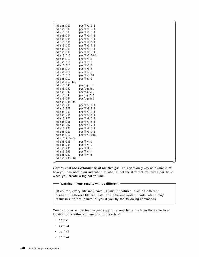
� �hdisk5:101 perflv1:1:1hdisk5:102 perflv1:2:1hdisk5:103 perflv1:3:1hdisk5:104 perflv1:4:1hdisk5:105 perflv1:5:1hdisk5:106 perflv1:6:1hdisk5:107 perflv1:7:1hdisk5:108 perflv1:8:1hdisk5:109 perflv1:9:1hdisk5:110 perflv1:10:1hdisk5:111 perflv3:1hdisk5:112 perflv3:2hdisk5:113 perflv3:5hdisk5:114 perflv3:6hdisk5:115 perflv3:9hdisk5:116 perflv3:10hdisk5:117 perflog:1hdisk5:118-139hdisk5:140 perfpg:1:1hdisk5:141 perfpg:3:1hdisk5:142 perfpg:5:1hdisk5:143 perfpg:2:2hdisk5:144 perfpg:4:2hdisk5:145-200hdisk5:201 perflv2:1:1hdisk5:202 perflv2:2:1hdisk5:203 perflv2:3:1hdisk5:204 perflv2:4:1hdisk5:205 perflv2:5:1hdisk5:206 perflv2:6:1hdisk5:207 perflv2:7:1hdisk5:208 perflv2:8:1hdisk5:209 perflv2:9:1hdisk5:210 perflv2:10:1hdisk5:211-232hdisk5:233 perflv4:1hdisk5:234 perflv4:2hdisk5:235 perflv4:3hdisk5:236 perflv4:4hdisk5:237 perflv4:5hdisk5:238-287� �
How to Test the Performance of the Design: This section gives an example ofhow you can obtain an indication of what effect the different attributes can havewhen you create a logical volume.
Warning - Your results will be different
Of course, every site may have its unique features, such as differenthardware, different I/O requests, and different system loads, which mayresult in different results for you if you try the following commands.
You can do a simple test by just copying a very large file from the same fixedlocation on another volume group to each of:
• perflv1
• perflv2
• perflv3
• perflv4
240 AIX Storage Management
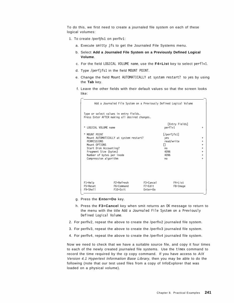
To do this, we first need to create a journaled file system on each of theselogical volumes:
1. To create /perfjfs1 on perflv1:
a. Execute smitty jfs to get the Journaled File Systems menu.
b. Select Add a Journaled File System on a Previously Defined LogicalVolume .
c. For the field LOGICAL VOLUME name, use the F4=List key to select perflv1.
d. Type /perfjfs1 in the field MOUNT POINT.
e. Change the field Mount AUTOMATICALLY at system restart? to yes by usingthe Tab key.
f. Leave the other fields with their default values so that the screen lookslike:
� �Add a Journaled File System on a Previously Defined Logical Volume
Type or select values in entry fields.Press Enter AFTER making all desired changes.
[Entry Fields]* LOGICAL VOLUME name perflv1 +
* MOUNT POINT [/perfjfs1]Mount AUTOMATICALLY at system restart? yes +PERMISSIONS read/write +Mount OPTIONS [] +Start Disk Accounting? no +Fragment Size (bytes) 4096 +Number of bytes per inode 4096 +Compression algorithm no +
F1=Help F2=Refresh F3=Cancel F4=ListF5=Reset F6=Command F7=Edit F8=ImageF9=Shell F10=Exit Enter=Do� �
g. Press the Enter=Do key.
h. Press the F3=Cancel key when smit returns an OK message to return tothe menu with the title Add a Journaled File System on a PreviouslyDefined Logical Volume.
2. For perflv2, repeat the above to create the /perflv2 journaled file system.
3. For perflv3, repeat the above to create the /perflv3 journaled file system.
4. For perflv4, repeat the above to create the /perflv4 journaled file system.
Now we need to check that we have a suitable source file, and copy it four timesto each of the newly created journaled file systems. Use the timex command torecord the time required by the cp copy command. If you have access to AIXVersion 4.1 Hypertext Information Base Library, then you may be able to do thefollowing (note that our test used files from a copy of InfoExplorer that wasloaded on a physical volume).
Chapter 8. Practical Examples 241
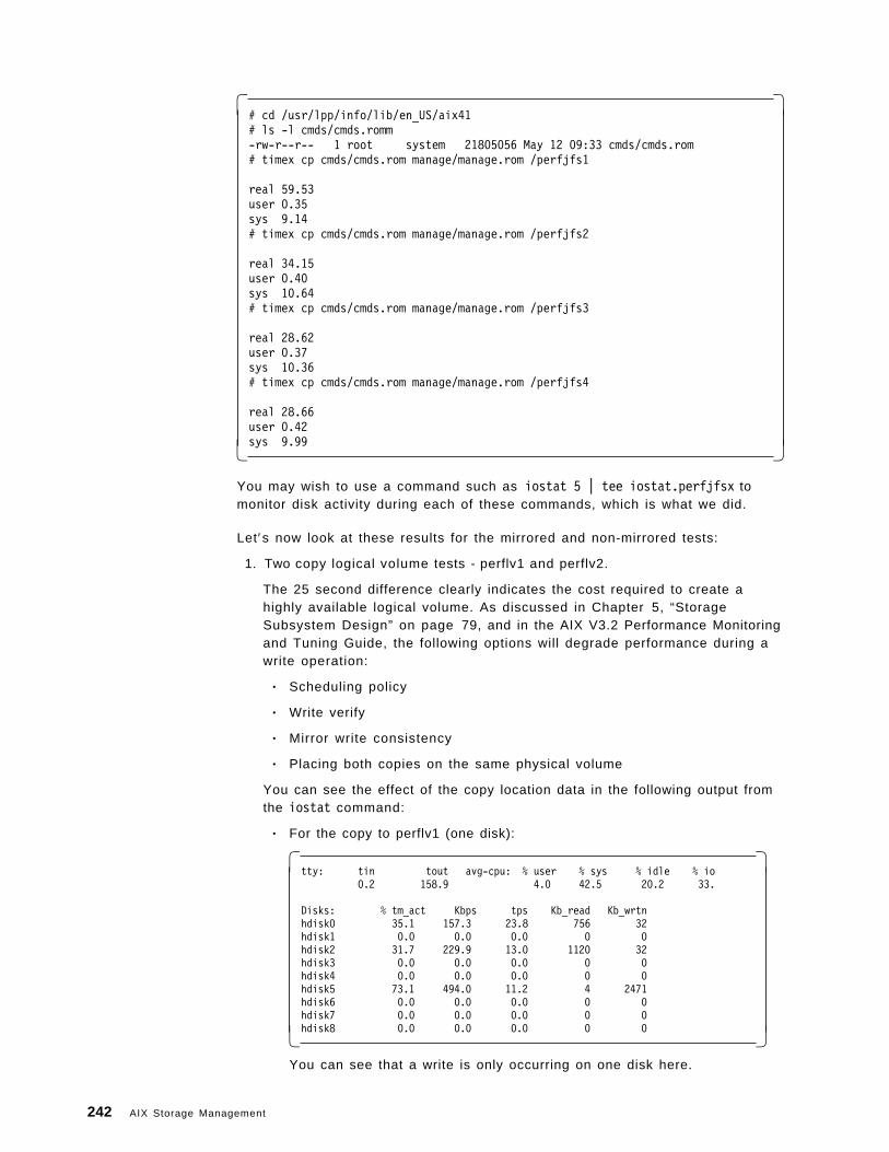
� �# cd /usr/lpp/info/lib/en_US/aix41# ls -l cmds/cmds.romm-rw-r--r-- 1 root system 21805056 May 12 09:33 cmds/cmds.rom# timex cp cmds/cmds.rom manage/manage.rom /perfjfs1
real 59.53user 0.35sys 9.14# timex cp cmds/cmds.rom manage/manage.rom /perfjfs2
real 34.15user 0.40sys 10.64# timex cp cmds/cmds.rom manage/manage.rom /perfjfs3
real 28.62user 0.37sys 10.36# timex cp cmds/cmds.rom manage/manage.rom /perfjfs4
real 28.66user 0.42sys 9.99� �
You may wish to use a command such as iostat 5 | tee iostat.perfjfsx tomonitor disk activity during each of these commands, which is what we did.
Let′s now look at these results for the mirrored and non-mirrored tests:
1. Two copy logical volume tests - perflv1 and perflv2.
The 25 second difference clearly indicates the cost required to create ahighly available logical volume. As discussed in Chapter 5, “StorageSubsystem Design” on page 79, and in the AIX V3.2 Performance Monitoringand Tuning Guide, the following options will degrade performance during awrite operation:
• Scheduling policy
• Write verify
• Mirror write consistency
• Placing both copies on the same physical volume
You can see the effect of the copy location data in the following output fromthe iostat command:
• For the copy to perflv1 (one disk):
� �tty: tin tout avg-cpu: % user % sys % idle % io
0.2 158.9 4.0 42.5 20.2 33.
Disks: % tm_act Kbps tps Kb_read Kb_wrtnhdisk0 35.1 157.3 23.8 756 32hdisk1 0.0 0.0 0.0 0 0hdisk2 31.7 229.9 13.0 1120 32hdisk3 0.0 0.0 0.0 0 0hdisk4 0.0 0.0 0.0 0 0hdisk5 73.1 494.0 11.2 4 2471hdisk6 0.0 0.0 0.0 0 0hdisk7 0.0 0.0 0.0 0 0hdisk8 0.0 0.0 0.0 0 0� �
You can see that a write is only occurring on one disk here.
242 AIX Storage Management
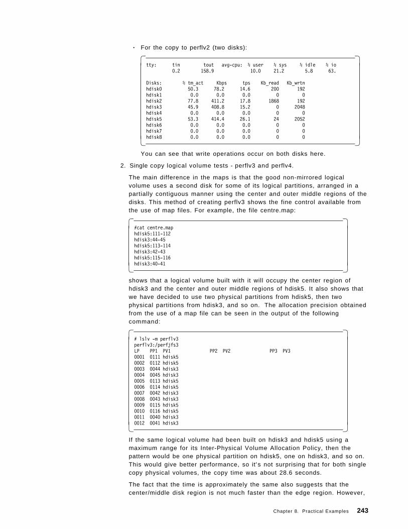
• For the copy to perflv2 (two disks):
� �tty: tin tout avg-cpu: % user % sys % idle % io
0.2 158.9 10.0 21.2 5.8 63.
Disks: % tm_act Kbps tps Kb_read Kb_wrtnhdisk0 50.3 78.2 14.6 200 192hdisk1 0.0 0.0 0.0 0 0hdisk2 77.8 411.2 17.8 1868 192hdisk3 45.9 408.8 15.2 0 2048hdisk4 0.0 0.0 0.0 0 0hdisk5 53.3 414.4 26.1 24 2052hdisk6 0.0 0.0 0.0 0 0hdisk7 0.0 0.0 0.0 0 0hdisk8 0.0 0.0 0.0 0 0� �
You can see that write operations occur on both disks here.
2. Single copy logical volume tests - perflv3 and perflv4.
The main difference in the maps is that the good non-mirrored logicalvolume uses a second disk for some of its logical partitions, arranged in apartially contiguous manner using the center and outer middle regions of thedisks. This method of creating perflv3 shows the fine control available fromthe use of map files. For example, the file centre.map:
� �#cat centre.maphdisk5:111-112hdisk3:44-45hdisk5:113-114hdisk3:42-43hdisk5:115-116hdisk3:40-41� �
shows that a logical volume built with it will occupy the center region ofhdisk3 and the center and outer middle regions of hdisk5. It also shows thatwe have decided to use two physical partitions from hdisk5, then twophysical partitions from hdisk3, and so on. The allocation precision obtainedfrom the use of a map file can be seen in the output of the followingcommand:
� �# lslv -m perflv3perflv3:/perfjfs3LP PP1 PV1 PP2 PV2 PP3 PV30001 0111 hdisk50002 0112 hdisk50003 0044 hdisk30004 0045 hdisk30005 0113 hdisk50006 0114 hdisk50007 0042 hdisk30008 0043 hdisk30009 0115 hdisk50010 0116 hdisk50011 0040 hdisk30012 0041 hdisk3� �
If the same logical volume had been built on hdisk3 and hdisk5 using amaximum range for its Inter-Physical Volume Allocation Policy, then thepattern would be one physical partition on hdisk5, one on hdisk3, and so on.This would give better performance, so it′s not surprising that for both singlecopy physical volumes, the copy time was about 28.6 seconds.
The fact that the time is approximately the same also suggests that thecenter/middle disk region is not much faster than the edge region. However,
Chapter 8. Practical Examples 243
this write had no competition from other disk requests so the disk heads willhave minimal movement across the disk platter regions.
One final performance result of interest is that in our scenario, mirroring alwaysdegraded performance, even when it was tuned for optimal performance. This isnot surprising since every logical write request is translated into two physicalwrite operations. However, you may obtain different results in anotherenvironment, particularly if your test is based on a read rather than a writeoperation, which we did not investigate here.
8.4 Managing Backup and RestoreIt is critically important that a systems administrator both implements andunderstands a reliable backup and recovery policy. This section shows you anexample of how to use the volume group backup utilities to save and recoveryour system, if your data or configuration information is damaged beyond apractical repair timeframe.
In particular, the examples in this section will describe:
• How to save the contents and configuration of the perfvg volume group.
• How to restore the contents and configuration of the perfvg volume group.
• How to use the mksysb command to save an image of the volume group.
• How to choose some of the storage management related installation optionsto reinstall this rootvg image.
244 AIX Storage Management
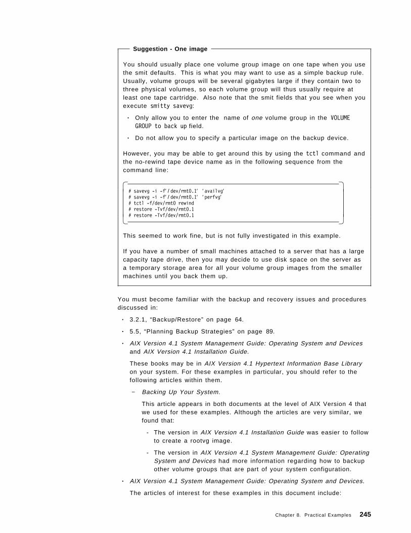
Suggestion - One image
You should usually place one volume group image on one tape when you usethe smit defaults. This is what you may want to use as a simple backup rule.Usually, volume groups will be several gigabytes large if they contain two tothree physical volumes, so each volume group will thus usually require atleast one tape cartridge. Also note that the smit fields that you see when youexecute smitty savevg:
• Only allow you to enter the name of one volume group in the VOLUMEGROUP to back up field.
• Do not allow you to specify a particular image on the backup device.
However, you may be able to get around this by using the tctl command andthe no-rewind tape device name as in the following sequence from thecommand line:
� �# savevg -i -f′ / dev/rmt0.1′ ′ availvg′# savevg -i -f′ / dev/rmt0.1′ ′ perfvg′# tctl -f/dev/rmt0 rewind# restore -Tvf/dev/rmt0.1# restore -Tvf/dev/rmt0.1� �
This seemed to work fine, but is not fully investigated in this example.
If you have a number of small machines attached to a server that has a largecapacity tape drive, then you may decide to use disk space on the server asa temporary storage area for all your volume group images from the smallermachines until you back them up.
You must become familiar with the backup and recovery issues and proceduresdiscussed in:
• 3.2.1, “Backup/Restore” on page 64.
• 5.5, “Planning Backup Strategies” on page 89.
• AIX Version 4.1 System Management Guide: Operating System and Devicesand AIX Version 4.1 Installation Guide.
These books may be in AIX Version 4.1 Hypertext Information Base Libraryon your system. For these examples in particular, you should refer to thefollowing articles within them.
− Backing Up Your System.
This article appears in both documents at the level of AIX Version 4 thatwe used for these examples. Although the articles are very similar, wefound that:
- The version in AIX Version 4.1 Installation Guide was easier to followto create a rootvg image.
- The version in AIX Version 4.1 System Management Guide: OperatingSystem and Devices had more information regarding how to backupother volume groups that are part of your system configuration.
• AIX Version 4.1 System Management Guide: Operating System and Devices.
The articles of interest for these examples in this document include:
Chapter 8. Practical Examples 245
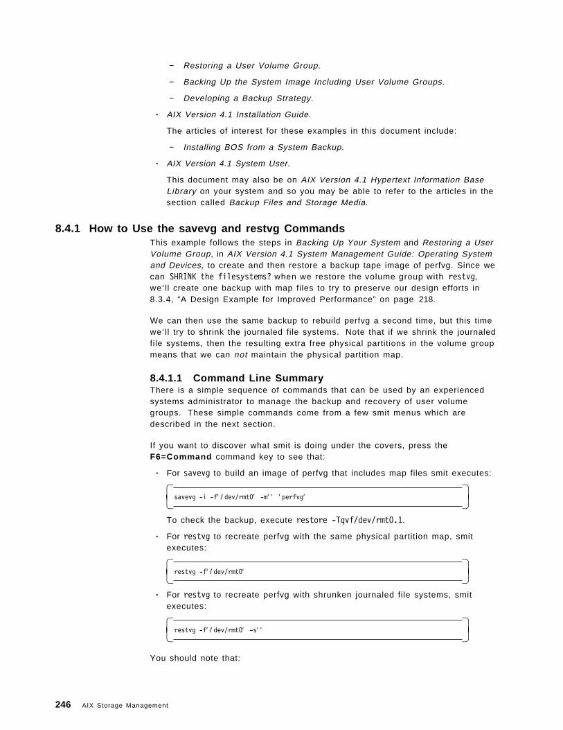
− Restoring a User Volume Group.
− Backing Up the System Image Including User Volume Groups.
− Developing a Backup Strategy.
• AIX Version 4.1 Installation Guide.
The articles of interest for these examples in this document include:
− Installing BOS from a System Backup.
• AIX Version 4.1 System User.
This document may also be on AIX Version 4.1 Hypertext Information BaseLibrary on your system and so you may be able to refer to the articles in thesection called Backup Files and Storage Media.
8.4.1 How to Use the savevg and restvg CommandsThis example follows the steps in Backing Up Your System and Restoring a UserVolume Group, in AIX Version 4.1 System Management Guide: Operating Systemand Devices, to create and then restore a backup tape image of perfvg. Since wecan SHRINK the filesystems? when we restore the volume group with restvg,we ′ ll create one backup with map files to try to preserve our design efforts in8.3.4, “A Design Example for Improved Performance” on page 218.
We can then use the same backup to rebuild perfvg a second time, but this timewe ′ ll try to shrink the journaled file systems. Note that if we shrink the journaledfile systems, then the resulting extra free physical partitions in the volume groupmeans that we can not maintain the physical partition map.
8.4.1.1 Command Line SummaryThere is a simple sequence of commands that can be used by an experiencedsystems administrator to manage the backup and recovery of user volumegroups. These simple commands come from a few smit menus which aredescribed in the next section.
If you want to discover what smit is doing under the covers, press theF6=Command command key to see that:
• For savevg to build an image of perfvg that includes map files smit executes:
� �savevg -i -f′ / dev/rmt0′ -m′ ′ ′ perfvg′� �
To check the backup, execute restore -Tqvf/dev/rmt0.1.
• For restvg to recreate perfvg with the same physical partition map, smitexecutes:
� �restvg -f′ / dev/rmt0′� �
• For restvg to recreate perfvg with shrunken journaled file systems, smitexecutes:
� �restvg -f′ / dev/rmt0′ -s′ ′� �
You should note that:
246 AIX Storage Management
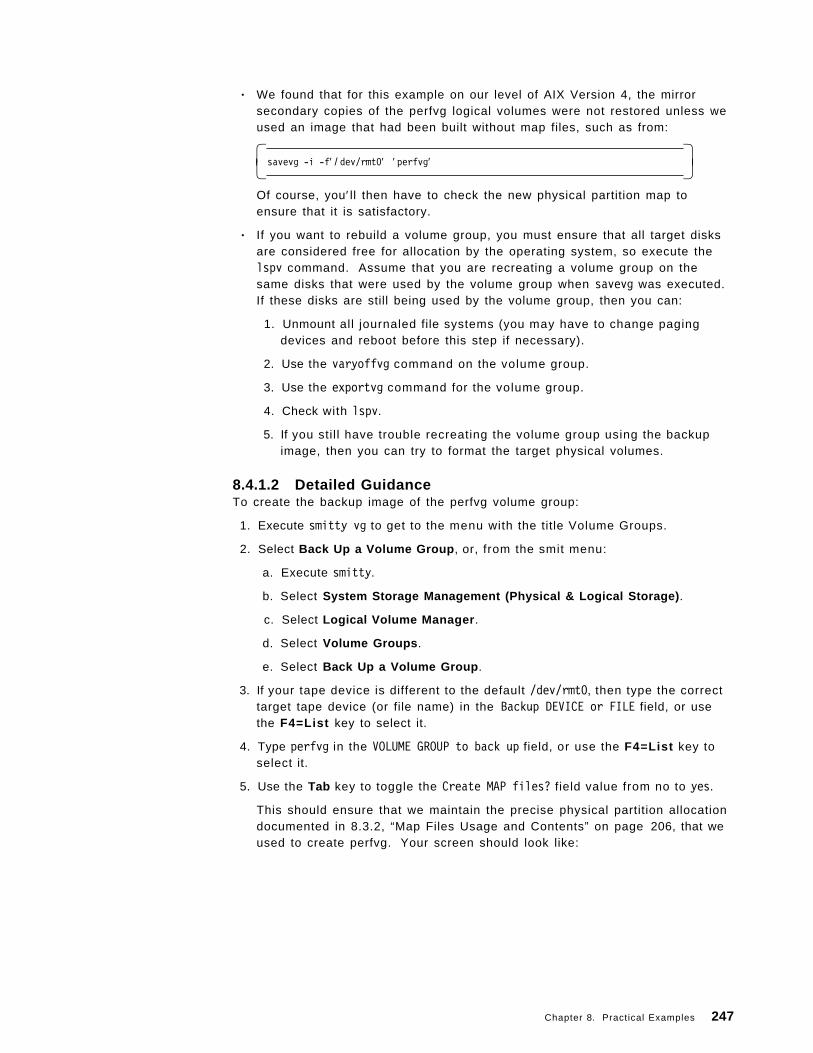
• We found that for this example on our level of AIX Version 4, the mirrorsecondary copies of the perfvg logical volumes were not restored unless weused an image that had been built without map files, such as from:
� �savevg -i -f′ / dev/rmt0′ ′ perfvg′� �
Of course, you′ ll then have to check the new physical partition map toensure that it is satisfactory.
• If you want to rebuild a volume group, you must ensure that all target disksare considered free for allocation by the operating system, so execute thelspv command. Assume that you are recreating a volume group on thesame disks that were used by the volume group when savevg was executed.If these disks are still being used by the volume group, then you can:
1. Unmount all journaled file systems (you may have to change pagingdevices and reboot before this step if necessary).
2. Use the varyoffvg command on the volume group.
3. Use the exportvg command for the volume group.
4. Check with lspv.
5. If you stil l have trouble recreating the volume group using the backupimage, then you can try to format the target physical volumes.
8.4.1.2 Detailed GuidanceTo create the backup image of the perfvg volume group:
1. Execute smitty vg to get to the menu with the title Volume Groups.
2. Select Back Up a Volume Group , or, from the smit menu:
a. Execute smitty.
b. Select System Storage Management (Physical & Logical Storage) .
c. Select Logical Volume Manager .
d. Select Volume Groups .
e. Select Back Up a Volume Group .
3. If your tape device is different to the default /dev/rmt0, then type the correcttarget tape device (or file name) in the Backup DEVICE or FILE field, or usethe F4=List key to select it.
4. Type perfvg in the VOLUME GROUP to back up field, or use the F4=List key toselect it.
5. Use the Tab key to toggle the Create MAP files? field value from no to yes.
This should ensure that we maintain the precise physical partition allocationdocumented in 8.3.2, “Map Files Usage and Contents” on page 206, that weused to create perfvg. Your screen should look like:
Chapter 8. Practical Examples 247
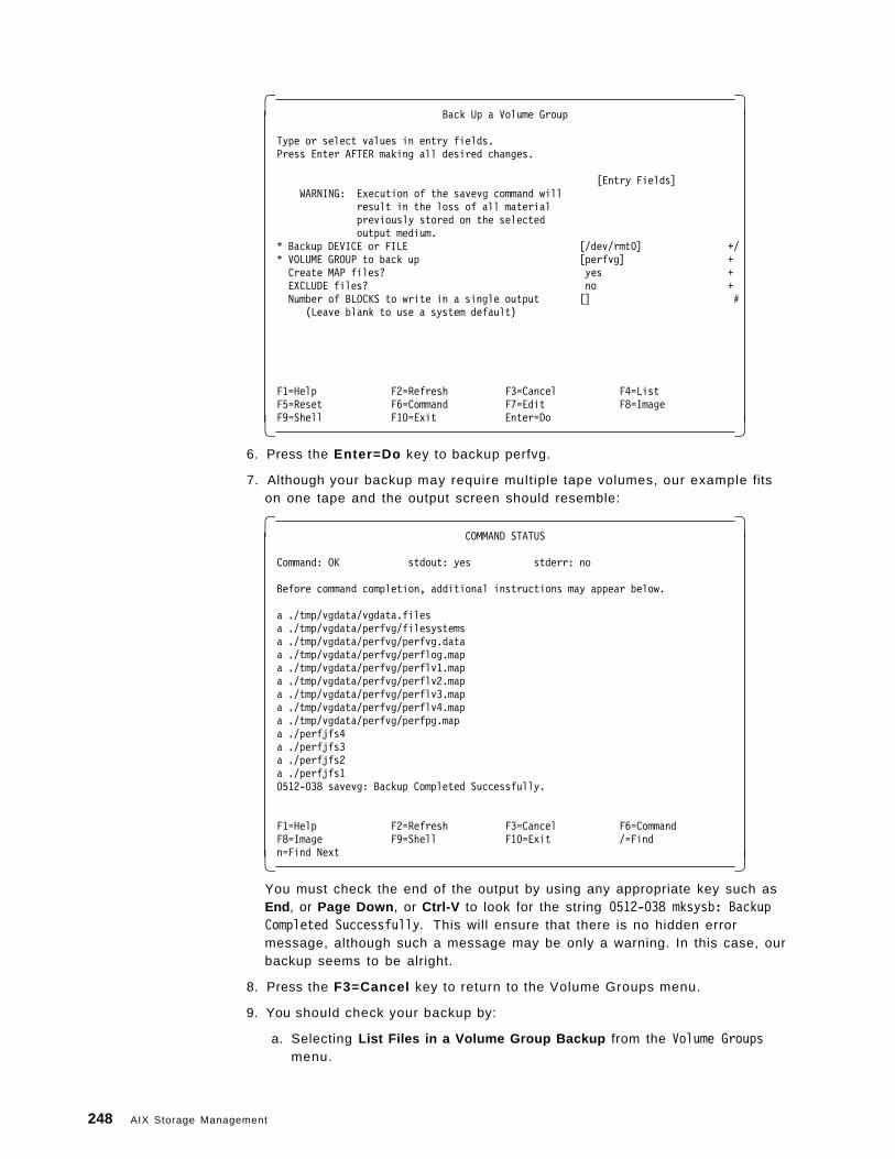
� �Back Up a Volume Group
Type or select values in entry fields.Press Enter AFTER making all desired changes.
[Entry Fields]WARNING: Execution of the savevg command will
result in the loss of all materialpreviously stored on the selectedoutput medium.
* Backup DEVICE or FILE [/dev/rmt0] +/* VOLUME GROUP to back up [perfvg] +Create MAP files? yes +EXCLUDE files? no +Number of BLOCKS to write in a single output [] #
(Leave blank to use a system default)
F1=Help F2=Refresh F3=Cancel F4=ListF5=Reset F6=Command F7=Edit F8=ImageF9=Shell F10=Exit Enter=Do� �
6. Press the Enter=Do key to backup perfvg.
7. Although your backup may require multiple tape volumes, our example fitson one tape and the output screen should resemble:
� �COMMAND STATUS
Command: OK stdout: yes stderr: no
Before command completion, additional instructions may appear below.
a ./tmp/vgdata/vgdata.filesa ./tmp/vgdata/perfvg/filesystemsa ./tmp/vgdata/perfvg/perfvg.dataa ./tmp/vgdata/perfvg/perflog.mapa ./tmp/vgdata/perfvg/perflv1.mapa ./tmp/vgdata/perfvg/perflv2.mapa ./tmp/vgdata/perfvg/perflv3.mapa ./tmp/vgdata/perfvg/perflv4.mapa ./tmp/vgdata/perfvg/perfpg.mapa ./perfjfs4a ./perfjfs3a ./perfjfs2a ./perfjfs10512-038 savevg: Backup Completed Successfully.
F1=Help F2=Refresh F3=Cancel F6=CommandF8=Image F9=Shell F10=Exit /=Findn=Find Next� �
You must check the end of the output by using any appropriate key such asEnd , or Page Down , or Ctrl-V to look for the string 0512-038 mksysb: BackupCompleted Successfully. This will ensure that there is no hidden errormessage, although such a message may be only a warning. In this case, ourbackup seems to be alright.
8. Press the F3=Cancel key to return to the Volume Groups menu.
9. You should check your backup by:
a. Selecting List Files in a Volume Group Backup from the Volume Groupsmenu.
248 AIX Storage Management
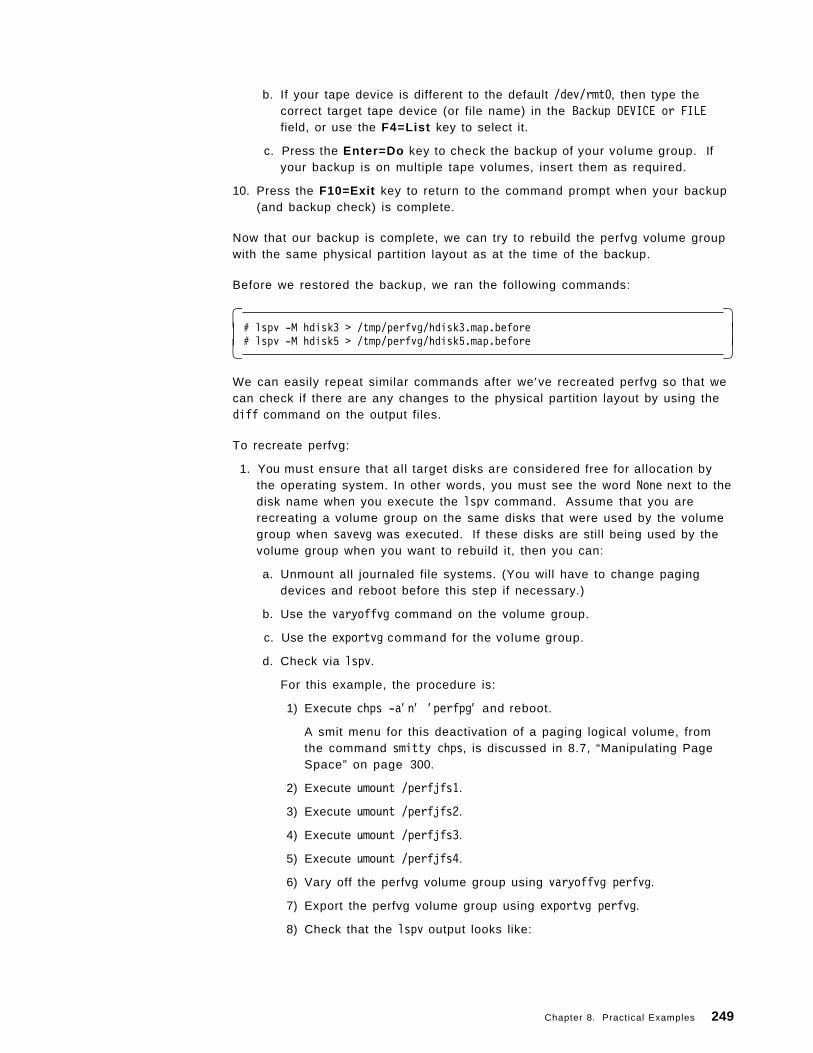
b. If your tape device is different to the default /dev/rmt0, then type thecorrect target tape device (or file name) in the Backup DEVICE or FILEfield, or use the F4=List key to select it.
c. Press the Enter=Do key to check the backup of your volume group. Ifyour backup is on multiple tape volumes, insert them as required.
10. Press the F10=Exit key to return to the command prompt when your backup(and backup check) is complete.
Now that our backup is complete, we can try to rebuild the perfvg volume groupwith the same physical partition layout as at the time of the backup.
Before we restored the backup, we ran the following commands:
� �# lspv -M hdisk3 > /tmp/perfvg/hdisk3.map.before# lspv -M hdisk5 > /tmp/perfvg/hdisk5.map.before� �
We can easily repeat similar commands after we′ve recreated perfvg so that wecan check if there are any changes to the physical partition layout by using thediff command on the output files.
To recreate perfvg:
1. You must ensure that all target disks are considered free for allocation bythe operating system. In other words, you must see the word None next to thedisk name when you execute the lspv command. Assume that you arerecreating a volume group on the same disks that were used by the volumegroup when savevg was executed. If these disks are still being used by thevolume group when you want to rebuild it, then you can:
a. Unmount all journaled file systems. (You will have to change pagingdevices and reboot before this step if necessary.)
b. Use the varyoffvg command on the volume group.
c. Use the exportvg command for the volume group.
d. Check via lspv.
For this example, the procedure is:
1) Execute chps -a′ n′ ′ perfpg′ and reboot.
A smit menu for this deactivation of a paging logical volume, fromthe command smitty chps, is discussed in 8.7, “Manipulating PageSpace” on page 300.
2) Execute umount /perfjfs1.
3) Execute umount /perfjfs2.
4) Execute umount /perfjfs3.
5) Execute umount /perfjfs4.
6) Vary off the perfvg volume group using varyoffvg perfvg.
7) Export the perfvg volume group using exportvg perfvg.
8) Check that the lspv output looks like:
Chapter 8. Practical Examples 249
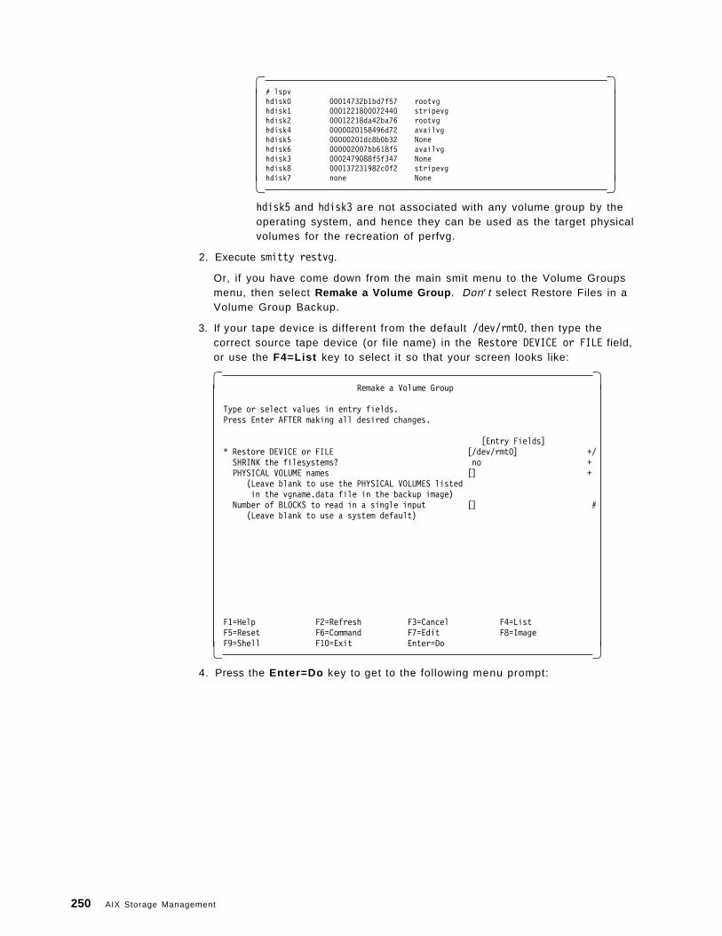
� �# lspvhdisk0 00014732b1bd7f57 rootvghdisk1 0001221800072440 stripevghdisk2 00012218da42ba76 rootvghdisk4 0000020158496d72 availvghdisk5 00000201dc8b0b32 Nonehdisk6 000002007bb618f5 availvghdisk3 0002479088f5f347 Nonehdisk8 000137231982c0f2 stripevghdisk7 none None� �
hdisk5 and hdisk3 are not associated with any volume group by theoperating system, and hence they can be used as the target physicalvolumes for the recreation of perfvg.
2. Execute smitty restvg.
Or, if you have come down from the main smit menu to the Volume Groupsmenu, then select Remake a Volume Group . Don′ t select Restore Files in aVolume Group Backup.
3. If your tape device is different from the default /dev/rmt0, then type thecorrect source tape device (or file name) in the Restore DEVICE or FILE field,or use the F4=List key to select it so that your screen looks like:
� �Remake a Volume Group
Type or select values in entry fields.Press Enter AFTER making all desired changes.
[Entry Fields]* Restore DEVICE or FILE [/dev/rmt0] +/SHRINK the filesystems? no +PHYSICAL VOLUME names [] +
(Leave blank to use the PHYSICAL VOLUMES listedin the vgname.data file in the backup image)
Number of BLOCKS to read in a single input [] #(Leave blank to use a system default)
F1=Help F2=Refresh F3=Cancel F4=ListF5=Reset F6=Command F7=Edit F8=ImageF9=Shell F10=Exit Enter=Do� �
4. Press the Enter=Do key to get to the following menu prompt:
250 AIX Storage Management
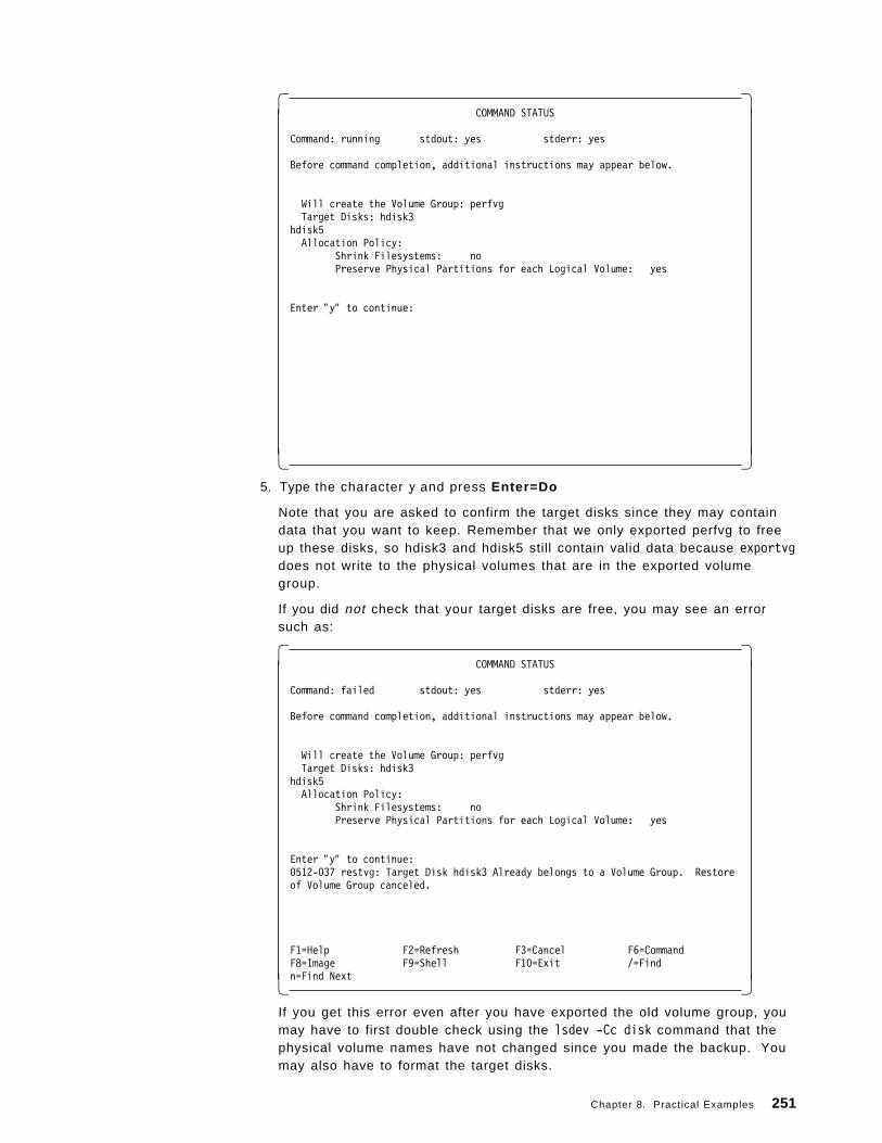
� �COMMAND STATUS
Command: running stdout: yes stderr: yes
Before command completion, additional instructions may appear below.
Will create the Volume Group: perfvgTarget Disks: hdisk3
hdisk5Allocation Policy:
Shrink Filesystems: noPreserve Physical Partitions for each Logical Volume: yes
Enter ″y″ to continue:
� � 5. Type the character y and press Enter=Do
Note that you are asked to confirm the target disks since they may containdata that you want to keep. Remember that we only exported perfvg to freeup these disks, so hdisk3 and hdisk5 still contain valid data because exportvgdoes not write to the physical volumes that are in the exported volumegroup.
If you did not check that your target disks are free, you may see an errorsuch as:
� �COMMAND STATUS
Command: failed stdout: yes stderr: yes
Before command completion, additional instructions may appear below.
Will create the Volume Group: perfvgTarget Disks: hdisk3
hdisk5Allocation Policy:
Shrink Filesystems: noPreserve Physical Partitions for each Logical Volume: yes
Enter ″y″ to continue:0512-037 restvg: Target Disk hdisk3 Already belongs to a Volume Group. Restoreof Volume Group canceled.
F1=Help F2=Refresh F3=Cancel F6=CommandF8=Image F9=Shell F10=Exit /=Findn=Find Next� �
If you get this error even after you have exported the old volume group, youmay have to first double check using the lsdev -Cc disk command that thephysical volume names have not changed since you made the backup. Youmay also have to format the target disks.
Chapter 8. Practical Examples 251
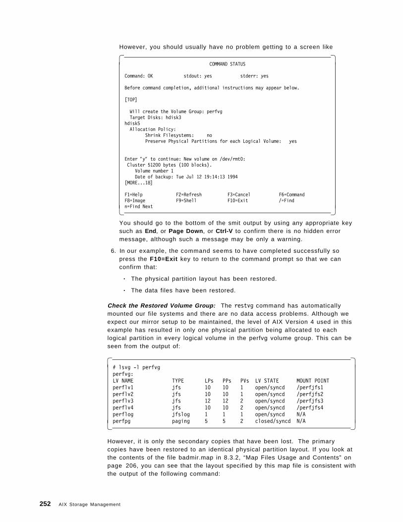
However, you should usually have no problem getting to a screen like
� �COMMAND STATUS
Command: OK stdout: yes stderr: yes
Before command completion, additional instructions may appear below.
[TOP]
Will create the Volume Group: perfvgTarget Disks: hdisk3
hdisk5Allocation Policy:
Shrink Filesystems: noPreserve Physical Partitions for each Logical Volume: yes
Enter ″y″ to continue: New volume on /dev/rmt0: Cluster 51200 bytes (100 blocks).
Volume number 1Date of backup: Tue Jul 12 19:14:13 1994
[MORE...18]
F1=Help F2=Refresh F3=Cancel F6=CommandF8=Image F9=Shell F10=Exit /=Findn=Find Next� �
You should go to the bottom of the smit output by using any appropriate keysuch as End , or Page Down , or Ctrl-V to confirm there is no hidden errormessage, although such a message may be only a warning.
6. In our example, the command seems to have completed successfully sopress the F10=Exit key to return to the command prompt so that we canconfirm that:
• The physical partition layout has been restored.
• The data files have been restored.
Check the Restored Volume Group: The restvg command has automaticallymounted our file systems and there are no data access problems. Although weexpect our mirror setup to be maintained, the level of AIX Version 4 used in thisexample has resulted in only one physical partition being allocated to eachlogical partition in every logical volume in the perfvg volume group. This can beseen from the output of:
� �# lsvg -l perfvgperfvg:LV NAME TYPE LPs PPs PVs LV STATE MOUNT POINTperflv1 jfs 10 10 1 open/syncd /perfjfs1perflv2 jfs 10 10 1 open/syncd /perfjfs2perflv3 jfs 12 12 2 open/syncd /perfjfs3perflv4 jfs 10 10 2 open/syncd /perfjfs4perflog jfslog 1 1 1 open/syncd N/Aperfpg paging 5 5 2 closed/syncd N/A� �
However, it is only the secondary copies that have been lost. The primarycopies have been restored to an identical physical partition layout. If you look atthe contents of the file badmir.map in 8.3.2, “Map Files Usage and Contents” onpage 206, you can see that the layout specified by this map file is consistent withthe output of the following command:
252 AIX Storage Management
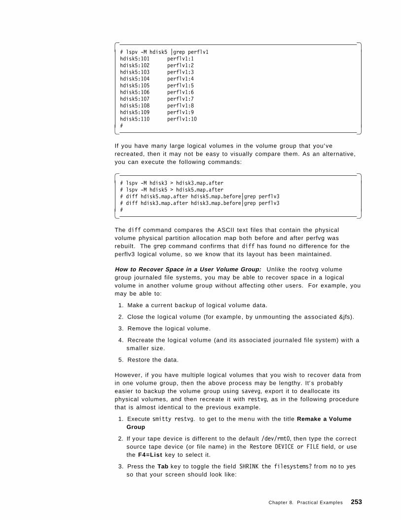
� �# lspv -M hdisk5 |grep perflv1hdisk5:101 perflv1:1hdisk5:102 perflv1:2hdisk5:103 perflv1:3hdisk5:104 perflv1:4hdisk5:105 perflv1:5hdisk5:106 perflv1:6hdisk5:107 perflv1:7hdisk5:108 perflv1:8hdisk5:109 perflv1:9hdisk5:110 perflv1:10#� �
If you have many large logical volumes in the volume group that you′verecreated, then it may not be easy to visually compare them. As an alternative,you can execute the following commands:
� �# lspv -M hdisk3 > hdisk3.map.after# lspv -M hdisk5 > hdisk5.map.after# diff hdisk5.map.after hdisk5.map.before|grep perflv3# diff hdisk3.map.after hdisk3.map.before|grep perflv3#� �
The diff command compares the ASCII text files that contain the physicalvolume physical partition allocation map both before and after perfvg wasrebuilt. The grep command confirms that diff has found no difference for theperflv3 logical volume, so we know that its layout has been maintained.
How to Recover Space in a User Volume Group: Unlike the rootvg volumegroup journaled file systems, you may be able to recover space in a logicalvolume in another volume group without affecting other users. For example, youmay be able to:
1. Make a current backup of logical volume data.
2. Close the logical volume (for example, by unmounting the associated &jfs).
3. Remove the logical volume.
4. Recreate the logical volume (and its associated journaled file system) with asmaller size.
5. Restore the data.
However, if you have multiple logical volumes that you wish to recover data fromin one volume group, then the above process may be lengthy. It′s probablyeasier to backup the volume group using savevg, export it to deallocate itsphysical volumes, and then recreate it with restvg, as in the following procedurethat is almost identical to the previous example.
1. Execute smitty restvg. to get to the menu with the title Remake a VolumeGroup
2. If your tape device is different to the default /dev/rmt0, then type the correctsource tape device (or file name) in the Restore DEVICE or FILE field, or usethe F4=List key to select it.
3. Press the Tab key to toggle the field SHRINK the filesystems? from no to yesso that your screen should look like:
Chapter 8. Practical Examples 253
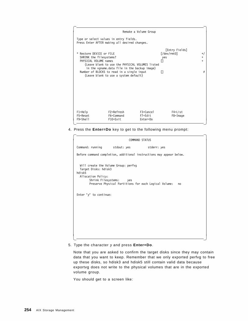
� �Remake a Volume Group
Type or select values in entry fields.Press Enter AFTER making all desired changes.
[Entry Fields]* Restore DEVICE or FILE [/dev/rmt0] +/SHRINK the filesystems? yes +PHYSICAL VOLUME names [] +
(Leave blank to use the PHYSICAL VOLUMES listedin the vgname.data file in the backup image)
Number of BLOCKS to read in a single input [] #(Leave blank to use a system default)
F1=Help F2=Refresh F3=Cancel F4=ListF5=Reset F6=Command F7=Edit F8=ImageF9=Shell F10=Exit Enter=Do� �
4. Press the Enter=Do key to get to the following menu prompt:
� �COMMAND STATUS
Command: running stdout: yes stderr: yes
Before command completion, additional instructions may appear below.
Will create the Volume Group: perfvgTarget Disks: hdisk3
hdisk5Allocation Policy:
Shrink Filesystems: yesPreserve Physical Partitions for each Logical Volume: no
Enter ″y″ to continue:
� � 5. Type the character y and press Enter=Do .
Note that you are asked to confirm the target disks since they may containdata that you want to keep. Remember that we only exported perfvg to freeup these disks, so hdisk3 and hdisk5 still contain valid data becauseexportvg does not write to the physical volumes that are in the exportedvolume group.
You should get to a screen like:
254 AIX Storage Management
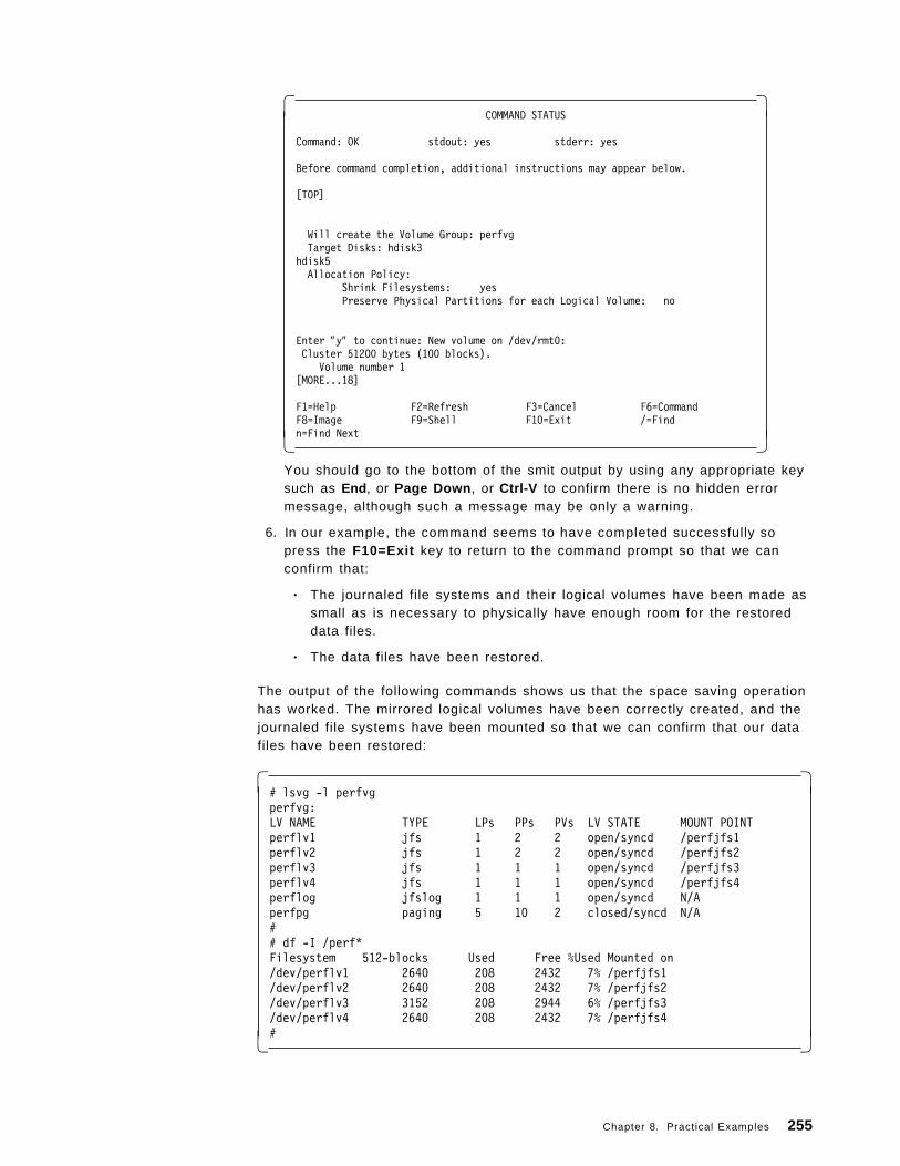
� �COMMAND STATUS
Command: OK stdout: yes stderr: yes
Before command completion, additional instructions may appear below.
[TOP]
Will create the Volume Group: perfvgTarget Disks: hdisk3
hdisk5Allocation Policy:
Shrink Filesystems: yesPreserve Physical Partitions for each Logical Volume: no
Enter ″y″ to continue: New volume on /dev/rmt0: Cluster 51200 bytes (100 blocks).
Volume number 1[MORE...18]
F1=Help F2=Refresh F3=Cancel F6=CommandF8=Image F9=Shell F10=Exit /=Findn=Find Next� �
You should go to the bottom of the smit output by using any appropriate keysuch as End , or Page Down , or Ctrl-V to confirm there is no hidden errormessage, although such a message may be only a warning.
6. In our example, the command seems to have completed successfully sopress the F10=Exit key to return to the command prompt so that we canconfirm that:
• The journaled file systems and their logical volumes have been made assmall as is necessary to physically have enough room for the restoreddata files.
• The data files have been restored.
The output of the following commands shows us that the space saving operationhas worked. The mirrored logical volumes have been correctly created, and thejournaled file systems have been mounted so that we can confirm that our datafiles have been restored:
� �# lsvg -l perfvgperfvg:LV NAME TYPE LPs PPs PVs LV STATE MOUNT POINTperflv1 jfs 1 2 2 open/syncd /perfjfs1perflv2 jfs 1 2 2 open/syncd /perfjfs2perflv3 jfs 1 1 1 open/syncd /perfjfs3perflv4 jfs 1 1 1 open/syncd /perfjfs4perflog jfslog 1 1 1 open/syncd N/Aperfpg paging 5 10 2 closed/syncd N/A## df -I /perf*Filesystem 512-blocks Used Free %Used Mounted on/dev/perflv1 2640 208 2432 7% /perfjfs1/dev/perflv2 2640 208 2432 7% /perfjfs2/dev/perflv3 3152 208 2944 6% /perfjfs3/dev/perflv4 2640 208 2432 7% /perfjfs4#� �
Chapter 8. Practical Examples 255
Note that although each journaled file system requires one 4MB logical partition,the journaled file system is actually much smaller than this, and can beexpanded to over 8000 512 byte blocks before a second logical partition will beallocated to it.
8.4.2 How to Use the mksysb CommandThis example follows the steps in ″Backing Up Your System″, in the AIX Version4.1 Installation Guide, to create a backup bootable tape image of rootvg. We cando this twice:
• One backup with map files.
• One backup without map files.
Since we are concerned about the location of our logical volume copies in ourmirrored rootvg example, we only need to do a backup that will create map files.In fact, creating map files provides more installation choices; we can change thefield in the installation menu from its default of yes so that we do not have to usethe map files on the tape to rebuild the rootvg.
Once the backup is complete, we can try to reinstall AIX Version 4 from ourbackup tape and confirm that the mirror copies are on separate physicalvolumes:
• With the default installation options (no maps and no shrink).
• With the map file installation option.
• With the shrink option set to yes.
Note that the entry for the image.data file in the AIX Version 3.2 Files Referencereminds us that this file in the / directory should not be modified.
8.4.2.1 Command Line SummaryUnlike AIX Version 3, the command called by smit is actually a script that for abootable tape effectively runs the following command:
� �# /usr/bin/mksysb -i $BFLAG $EFLAG $MFLAG $DEVICE� �
The script that is actually run is a great deal more complicated, and can beviewed by using the F6=Command key from the smit Back Up the System menu.
8.4.2.2 Detailed GuidanceOur first example shows how to create a backup that includes map files for therootvg. This should enable us to use this backup tape to rebuild a system thathas the same disk configuration, with the physical partitions of each logicalvolume located in exactly the same place. This will ensure that your systemperformance does not suffer because, for example, a paging logical volumecould otherwise be rebuilt on a slow physical volume instead of the fast physicalvolume that it was on when the AIX Version 4 rootvg image was built.
Always Document the Current System: Before we start any backup, it is wise tocollect the output of a few commands to document the current systemconfiguration. This information may be very valuable if you encounter a problemwhen you use this backup image to install AIX Version 4.
256 AIX Storage Management
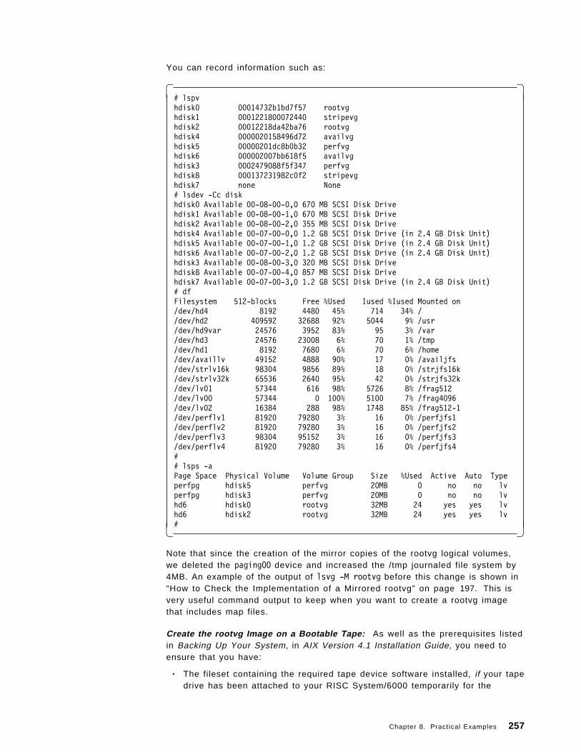
You can record information such as:
� �# lspvhdisk0 00014732b1bd7f57 rootvghdisk1 0001221800072440 stripevghdisk2 00012218da42ba76 rootvghdisk4 0000020158496d72 availvghdisk5 00000201dc8b0b32 perfvghdisk6 000002007bb618f5 availvghdisk3 0002479088f5f347 perfvghdisk8 000137231982c0f2 stripevghdisk7 none None# lsdev -Cc diskhdisk0 Available 00-08-00-0,0 670 MB SCSI Disk Drivehdisk1 Available 00-08-00-1,0 670 MB SCSI Disk Drivehdisk2 Available 00-08-00-2,0 355 MB SCSI Disk Drivehdisk4 Available 00-07-00-0,0 1.2 GB SCSI Disk Drive (in 2.4 GB Disk Unit)hdisk5 Available 00-07-00-1,0 1.2 GB SCSI Disk Drive (in 2.4 GB Disk Unit)hdisk6 Available 00-07-00-2,0 1.2 GB SCSI Disk Drive (in 2.4 GB Disk Unit)hdisk3 Available 00-08-00-3,0 320 MB SCSI Disk Drivehdisk8 Available 00-07-00-4,0 857 MB SCSI Disk Drivehdisk7 Available 00-07-00-3,0 1.2 GB SCSI Disk Drive (in 2.4 GB Disk Unit)# dfFilesystem 512-blocks Free %Used Iused %Iused Mounted on/dev/hd4 8192 4480 45% 714 34% //dev/hd2 409592 32688 92% 5044 9% /usr/dev/hd9var 24576 3952 83% 95 3% /var/dev/hd3 24576 23008 6% 70 1% /tmp/dev/hd1 8192 7680 6% 70 6% /home/dev/availlv 49152 4888 90% 17 0% /availjfs/dev/strlv16k 98304 9856 89% 18 0% /strjfs16k/dev/strlv32k 65536 2640 95% 42 0% /strjfs32k/dev/lv01 57344 616 98% 5726 8% /frag512/dev/lv00 57344 0 100% 5100 7% /frag4096/dev/lv02 16384 288 98% 1748 85% /frag512-1/dev/perflv1 81920 79280 3% 16 0% /perfjfs1/dev/perflv2 81920 79280 3% 16 0% /perfjfs2/dev/perflv3 98304 95152 3% 16 0% /perfjfs3/dev/perflv4 81920 79280 3% 16 0% /perfjfs4## lsps -aPage Space Physical Volume Volume Group Size %Used Active Auto Typeperfpg hdisk5 perfvg 20MB 0 no no lvperfpg hdisk3 perfvg 20MB 0 no no lvhd6 hdisk0 rootvg 32MB 24 yes yes lvhd6 hdisk2 rootvg 32MB 24 yes yes lv#� �
Note that since the creation of the mirror copies of the rootvg logical volumes,we deleted the paging00 device and increased the /tmp journaled file system by4MB. An example of the output of lsvg -M rootvg before this change is shown in“How to Check the Implementation of a Mirrored rootvg” on page 197. This isvery useful command output to keep when you want to create a rootvg imagethat includes map files.
Create the rootvg Image on a Bootable Tape: As well as the prerequisites listedin Backing Up Your System, in AIX Version 4.1 Installation Guide, you need toensure that you have:
• The fileset containing the required tape device software installed, if your tapedrive has been attached to your RISC System/6000 temporarily for the
Chapter 8. Practical Examples 257
purpose of backing it up (in other words, the tape device was not poweredon and attached to this RISC System/6000 when it was previously installed).
• Given thought to the consequences of using this rootvg image to install adifferent RISC System/6000. In other words, do you need to:
− Change the root password before the backup.
− Install additional filesets containing device driver software for the targetmachine if its hardware configuration is not identical to the source RISCSystem/6000 where the image was created.
− Change communication parameters to avoid a network conflict.
We can see from the above output of the df command that we have 23008 512byte blocks free in the /tmp journaled file system. This is more than 8.2MB, sowe should have enough working space for the backup process. However, even ifdf said that /tmp was almost full or on the borderline of being likely to run out ofspace, then since we know that rootvg has some free physical partitions in it, wecan just change the smit field EXPAND /tmp if needed? as described below. Wealso know that all the rootvg journaled file systems that we want to backup arecurrently mounted. To create the rootvg image:
1. Execute the command smitty mksysb.
If you want to find this in the AIX Version 4 smit menu hierarchy:
a. Execute the command smitty.
b. Select System Storage Management (Physical & Logical Storage) .
c. Select System Backup Manager .
d. Select Back Up the System .
Your screen should now have a menu with the title Back Up the System.
2. Type the name of our backup device, such as /dev/rmt0, in the Backup DEVICEor FILE field if its different to the default value that appears in the field.
3. Ensure that we ′ l l have enough working space by using the Tab key to toggleEXPAND /tmp if needed? to no.
4. Use the Tab key to toggle Create MAP files? from no to yes so that yourscreen looks like:
258 AIX Storage Management
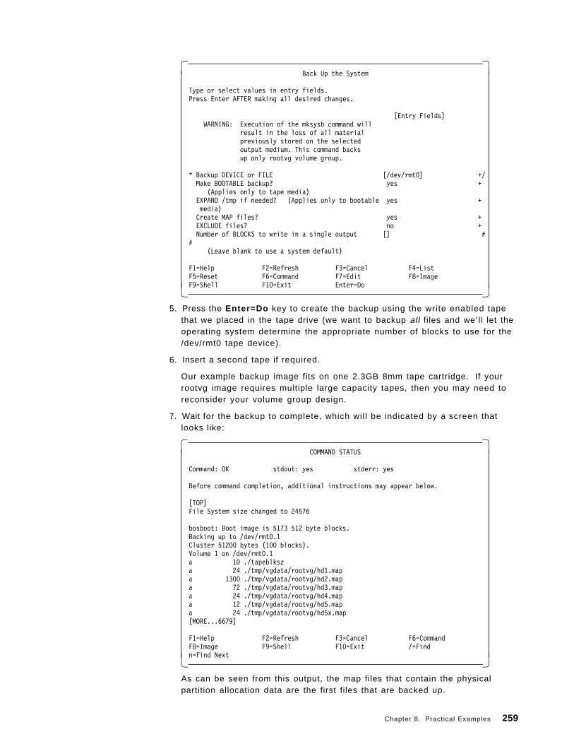
� �Back Up the System
Type or select values in entry fields.Press Enter AFTER making all desired changes.
[Entry Fields]WARNING: Execution of the mksysb command will
result in the loss of all materialpreviously stored on the selectedoutput medium. This command backsup only rootvg volume group.
* Backup DEVICE or FILE [/dev/rmt0] +/Make BOOTABLE backup? yes +
(Applies only to tape media)EXPAND /tmp if needed? (Applies only to bootable yes +media)Create MAP files? yes +EXCLUDE files? no +Number of BLOCKS to write in a single output [] #
#(Leave blank to use a system default)
F1=Help F2=Refresh F3=Cancel F4=ListF5=Reset F6=Command F7=Edit F8=ImageF9=Shell F10=Exit Enter=Do� �
5. Press the Enter=Do key to create the backup using the write enabled tapethat we placed in the tape drive (we want to backup all files and we′ ll let theoperating system determine the appropriate number of blocks to use for the/dev/rmt0 tape device).
6. Insert a second tape if required.
Our example backup image fits on one 2.3GB 8mm tape cartridge. If yourrootvg image requires multiple large capacity tapes, then you may need toreconsider your volume group design.
7. Wait for the backup to complete, which will be indicated by a screen thatlooks like:
� �COMMAND STATUS
Command: OK stdout: yes stderr: yes
Before command completion, additional instructions may appear below.
[TOP]File System size changed to 24576
bosboot: Boot image is 5173 512 byte blocks.Backing up to /dev/rmt0.1Cluster 51200 bytes (100 blocks).Volume 1 on /dev/rmt0.1a 10 ./tapeblksza 24 ./tmp/vgdata/rootvg/hd1.mapa 1300 ./tmp/vgdata/rootvg/hd2.mapa 72 ./tmp/vgdata/rootvg/hd3.mapa 24 ./tmp/vgdata/rootvg/hd4.mapa 12 ./tmp/vgdata/rootvg/hd5.mapa 24 ./tmp/vgdata/rootvg/hd5x.map[MORE...6679]
F1=Help F2=Refresh F3=Cancel F6=CommandF8=Image F9=Shell F10=Exit /=Findn=Find Next� �
As can be seen from this output, the map files that contain the physicalpartition allocation data are the first files that are backed up.
Chapter 8. Practical Examples 259
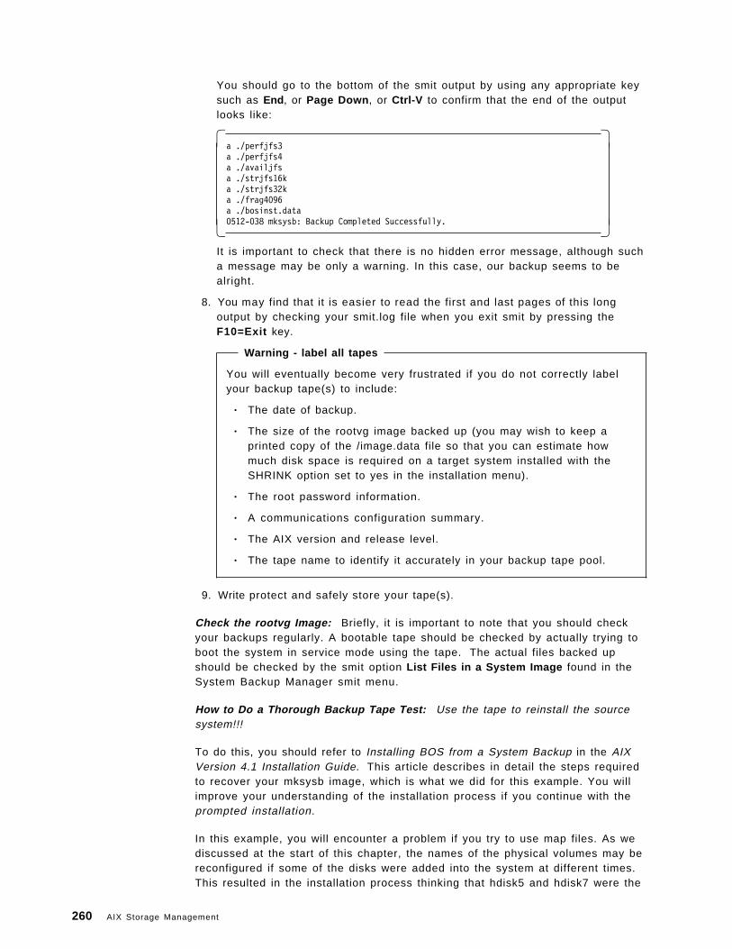
You should go to the bottom of the smit output by using any appropriate keysuch as End , or Page Down , or Ctrl-V to confirm that the end of the outputlooks like:
� �a ./perfjfs3a ./perfjfs4a ./availjfsa ./strjfs16ka ./strjfs32ka ./frag4096a ./bosinst.data0512-038 mksysb: Backup Completed Successfully.� �
It is important to check that there is no hidden error message, although sucha message may be only a warning. In this case, our backup seems to bealright.
8. You may find that it is easier to read the first and last pages of this longoutput by checking your smit.log file when you exit smit by pressing theF10=Exit key.
Warning - label all tapes
You will eventually become very frustrated if you do not correctly labelyour backup tape(s) to include:
• The date of backup.
• The size of the rootvg image backed up (you may wish to keep aprinted copy of the /image.data file so that you can estimate howmuch disk space is required on a target system installed with theSHRINK option set to yes in the installation menu).
• The root password information.
• A communications configuration summary.
• The AIX version and release level.
• The tape name to identify it accurately in your backup tape pool.
9. Write protect and safely store your tape(s).
Check the rootvg Image: Briefly, it is important to note that you should checkyour backups regularly. A bootable tape should be checked by actually trying toboot the system in service mode using the tape. The actual files backed upshould be checked by the smit option List Files in a System Image found in theSystem Backup Manager smit menu.
How to Do a Thorough Backup Tape Test: Use the tape to reinstall the sourcesystem!!!
To do this, you should refer to Installing BOS from a System Backup in the AIXVersion 4.1 Installation Guide. This article describes in detail the steps requiredto recover your mksysb image, which is what we did for this example. You willimprove your understanding of the installation process if you continue with theprompted installation.
In this example, you will encounter a problem if you try to use map files. As wediscussed at the start of this chapter, the names of the physical volumes may bereconfigured if some of the disks were added into the system at different times.This resulted in the installation process thinking that hdisk5 and hdisk7 were the
260 AIX Storage Management
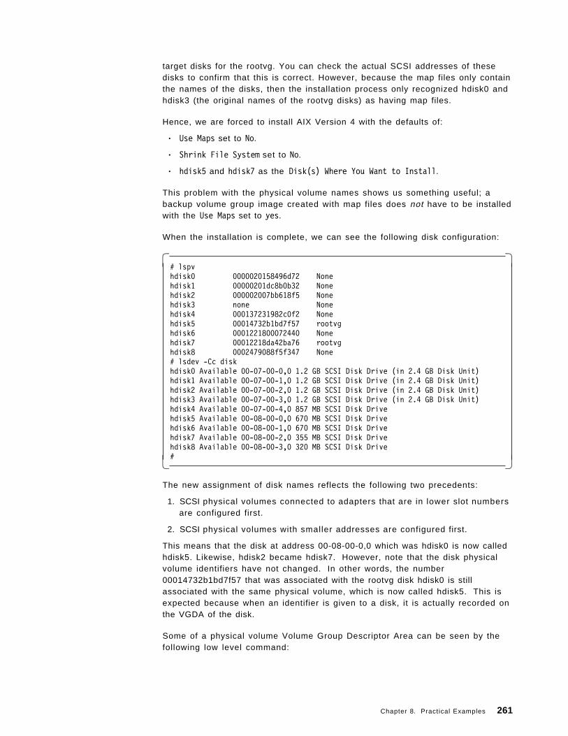
target disks for the rootvg. You can check the actual SCSI addresses of thesedisks to confirm that this is correct. However, because the map files only containthe names of the disks, then the installation process only recognized hdisk0 andhdisk3 (the original names of the rootvg disks) as having map files.
Hence, we are forced to install AIX Version 4 with the defaults of:
• Use Maps set to No.
• Shrink File System set to No.
• hdisk5 and hdisk7 as the Disk(s) Where You Want to Install.
This problem with the physical volume names shows us something useful; abackup volume group image created with map files does not have to be installedwith the Use Maps set to yes.
When the installation is complete, we can see the following disk configuration:
� �# lspvhdisk0 0000020158496d72 Nonehdisk1 00000201dc8b0b32 Nonehdisk2 000002007bb618f5 Nonehdisk3 none Nonehdisk4 000137231982c0f2 Nonehdisk5 00014732b1bd7f57 rootvghdisk6 0001221800072440 Nonehdisk7 00012218da42ba76 rootvghdisk8 0002479088f5f347 None# lsdev -Cc diskhdisk0 Available 00-07-00-0,0 1.2 GB SCSI Disk Drive (in 2.4 GB Disk Unit)hdisk1 Available 00-07-00-1,0 1.2 GB SCSI Disk Drive (in 2.4 GB Disk Unit)hdisk2 Available 00-07-00-2,0 1.2 GB SCSI Disk Drive (in 2.4 GB Disk Unit)hdisk3 Available 00-07-00-3,0 1.2 GB SCSI Disk Drive (in 2.4 GB Disk Unit)hdisk4 Available 00-07-00-4,0 857 MB SCSI Disk Drivehdisk5 Available 00-08-00-0,0 670 MB SCSI Disk Drivehdisk6 Available 00-08-00-1,0 670 MB SCSI Disk Drivehdisk7 Available 00-08-00-2,0 355 MB SCSI Disk Drivehdisk8 Available 00-08-00-3,0 320 MB SCSI Disk Drive#� �
The new assignment of disk names reflects the following two precedents:
1. SCSI physical volumes connected to adapters that are in lower slot numbersare configured first.
2. SCSI physical volumes with smaller addresses are configured first.
This means that the disk at address 00-08-00-0,0 which was hdisk0 is now calledhdisk5. Likewise, hdisk2 became hdisk7. However, note that the disk physicalvolume identifiers have not changed. In other words, the number00014732b1bd7f57 that was associated with the rootvg disk hdisk0 is stillassociated with the same physical volume, which is now called hdisk5. This isexpected because when an identifier is given to a disk, it is actually recorded onthe VGDA of the disk.
Some of a physical volume Volume Group Descriptor Area can be seen by thefollowing low level command:
Chapter 8. Practical Examples 261
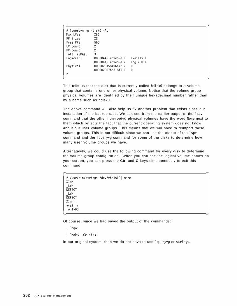
� �# lqueryvg -p hdisk0 -AtMax LVs: 256PP Size: 22Free PPs: 560LV count: 2PV count: 2Total VGDAs: 3Logical: 000004461ed9e52e.1 availlv 1
000004461ed9e52e.2 loglv00 1Physical: 0000020158496d72 2 0
000002007bb618f5 1 0#� �
This tells us that the disk that is currently called hdisk0 belongs to a volumegroup that contains one other physical volume. Notice that the volume groupphysical volumes are identified by their unique hexadecimal number rather thanby a name such as hdisk0.
The above command will also help us fix another problem that exists since ourinstallation of the backup tape. We can see from the earlier output of the lspvcommand that the other non-rootvg physical volumes have the word None next tothem which reflects the fact that the current operating system does not knowabout our user volume groups. This means that we will have to reimport thesevolume groups. This is not difficult since we can use the output of the lspvcommand and the lqueryvg command for some of the disks to determine howmany user volume groups we have.
Alternatively, we could use the following command for every disk to determinethe volume group configuration. When you can see the logical volume names onyour screen, you can press the Ctrl and C keys simultaneously to exit thiscommand.
� �# /usr/bin/strings /dev/rhdisk0| moreXImr_LVMDEFECT_LVMDEFECTXImravaillvloglv00� �
Of course, since we had saved the output of the commands:
• lspv
• lsdev -Cc disk
in our original system, then we do not have to use lqueryvg or strings.
262 AIX Storage Management
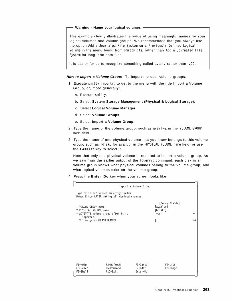
Warning - Name your logical volumes
This example clearly illustrates the value of using meaningful names for yourlogical volumes and volume groups. We recommended that you always usethe option Add a Journaled File System on a Previously Defined LogicalVolume in the menu found from smitty jfs, rather than Add a Journaled FileSystem for long term data files.
It is easier for us to recognize something called availlv rather than lv00.
How to Import a Volume Group: To import the user volume groups:
1. Execute smitty importvg to get to the menu with the title Import a VolumeGroup, or, more generally:
a. Execute smitty.
b. Select System Storage Management (Physical & Logical Storage) .
c. Select Logical Volume Manager .
d. Select Volume Groups .
e. Select Import a Volume Group .
2. Type the name of the volume group, such as availvg, in the VOLUME GROUPname field.
3. Type the name of one physical volume that you know belongs to this volumegroup, such as hdisk0 for availvg, in the PHYSICAL VOLUME name field, or usethe F4=List key to select it.
Note that only one physical volume is required to import a volume group. Aswe saw from the earlier output of the lqueryvg command, each disk in avolume group knows what physical volumes belong to the volume group, andwhat logical volumes exist on the volume group.
4. Press the Enter=Do key when your screen looks like:
� �Import a Volume Group
Type or select values in entry fields.Press Enter AFTER making all desired changes.
[Entry Fields]VOLUME GROUP name [availvg]
* PHYSICAL VOLUME name [hdisk0] +* ACTIVATE volume group after it is yes +
imported?Volume group MAJOR NUMBER [] +#
F1=Help F2=Refresh F3=Cancel F4=ListF5=Reset F6=Command F7=Edit F8=ImageF9=Shell F10=Exit Enter=Do� �
Chapter 8. Practical Examples 263
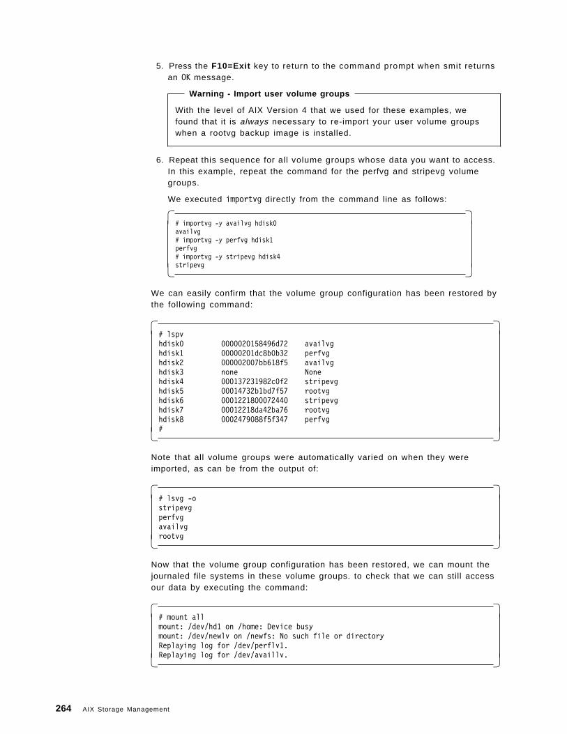
5. Press the F10=Exit key to return to the command prompt when smit returnsan OK message.
Warning - Import user volume groups
With the level of AIX Version 4 that we used for these examples, wefound that it is always necessary to re-import your user volume groupswhen a rootvg backup image is installed.
6. Repeat this sequence for all volume groups whose data you want to access.In this example, repeat the command for the perfvg and stripevg volumegroups.
We executed importvg directly from the command line as follows:
� �# importvg -y availvg hdisk0availvg# importvg -y perfvg hdisk1perfvg# importvg -y stripevg hdisk4stripevg� �
We can easily confirm that the volume group configuration has been restored bythe following command:
� �# lspvhdisk0 0000020158496d72 availvghdisk1 00000201dc8b0b32 perfvghdisk2 000002007bb618f5 availvghdisk3 none Nonehdisk4 000137231982c0f2 stripevghdisk5 00014732b1bd7f57 rootvghdisk6 0001221800072440 stripevghdisk7 00012218da42ba76 rootvghdisk8 0002479088f5f347 perfvg#� �
Note that all volume groups were automatically varied on when they wereimported, as can be from the output of:
� �# lsvg -ostripevgperfvgavailvgrootvg� �
Now that the volume group configuration has been restored, we can mount thejournaled file systems in these volume groups. to check that we can still accessour data by executing the command:
� �# mount allmount: /dev/hd1 on /home: Device busymount: /dev/newlv on /newfs: No such file or directoryReplaying log for /dev/perflv1.Replaying log for /dev/availlv.� �
264 AIX Storage Management
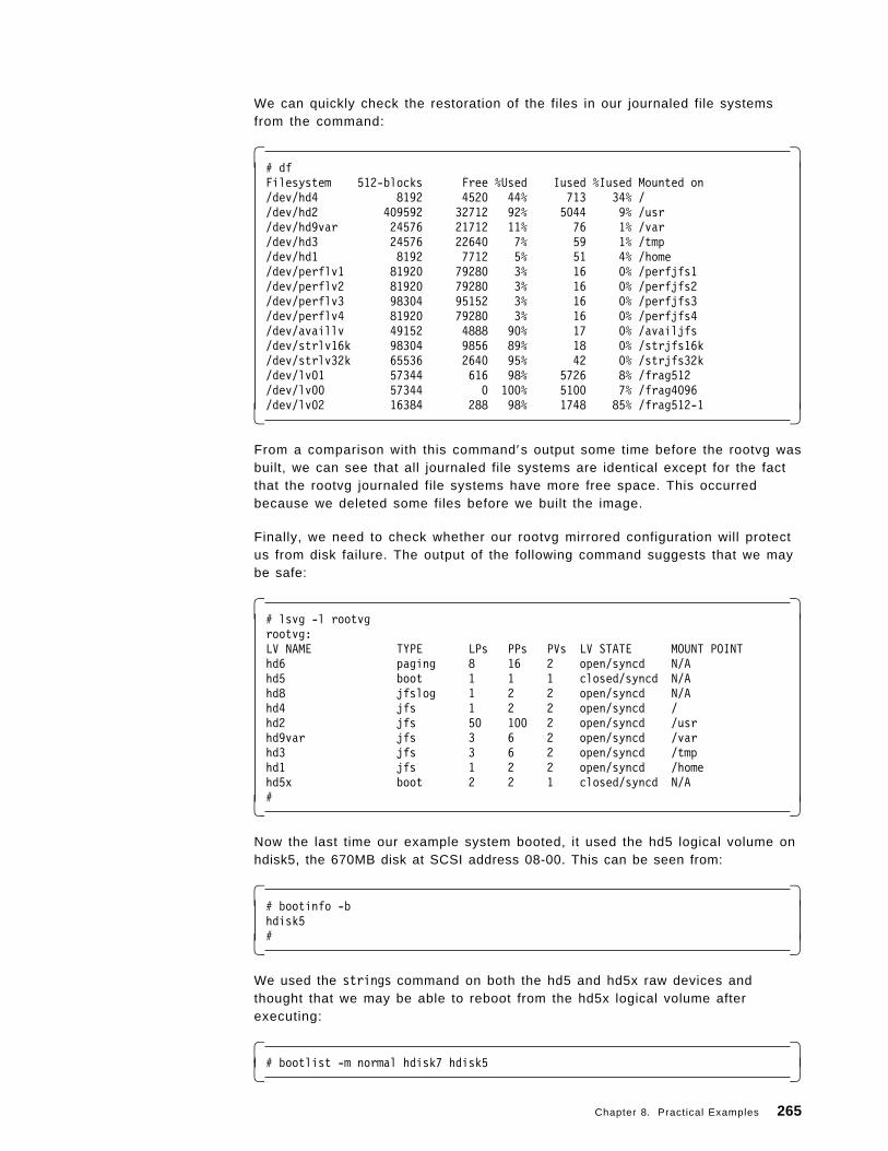
We can quickly check the restoration of the files in our journaled file systemsfrom the command:
� �# dfFilesystem 512-blocks Free %Used Iused %Iused Mounted on/dev/hd4 8192 4520 44% 713 34% //dev/hd2 409592 32712 92% 5044 9% /usr/dev/hd9var 24576 21712 11% 76 1% /var/dev/hd3 24576 22640 7% 59 1% /tmp/dev/hd1 8192 7712 5% 51 4% /home/dev/perflv1 81920 79280 3% 16 0% /perfjfs1/dev/perflv2 81920 79280 3% 16 0% /perfjfs2/dev/perflv3 98304 95152 3% 16 0% /perfjfs3/dev/perflv4 81920 79280 3% 16 0% /perfjfs4/dev/availlv 49152 4888 90% 17 0% /availjfs/dev/strlv16k 98304 9856 89% 18 0% /strjfs16k/dev/strlv32k 65536 2640 95% 42 0% /strjfs32k/dev/lv01 57344 616 98% 5726 8% /frag512/dev/lv00 57344 0 100% 5100 7% /frag4096/dev/lv02 16384 288 98% 1748 85% /frag512-1� �
From a comparison with this command′s output some time before the rootvg wasbuilt, we can see that all journaled file systems are identical except for the factthat the rootvg journaled file systems have more free space. This occurredbecause we deleted some files before we built the image.
Finally, we need to check whether our rootvg mirrored configuration will protectus from disk failure. The output of the following command suggests that we maybe safe:
� �# lsvg -l rootvgrootvg:LV NAME TYPE LPs PPs PVs LV STATE MOUNT POINThd6 paging 8 16 2 open/syncd N/Ahd5 boot 1 1 1 closed/syncd N/Ahd8 jfslog 1 2 2 open/syncd N/Ahd4 jfs 1 2 2 open/syncd /hd2 jfs 50 100 2 open/syncd /usrhd9var jfs 3 6 2 open/syncd /varhd3 jfs 3 6 2 open/syncd /tmphd1 jfs 1 2 2 open/syncd /homehd5x boot 2 2 1 closed/syncd N/A#� �
Now the last time our example system booted, it used the hd5 logical volume onhdisk5, the 670MB disk at SCSI address 08-00. This can be seen from:
� �# bootinfo -bhdisk5#� �
We used the strings command on both the hd5 and hd5x raw devices andthought that we may be able to reboot from the hd5x logical volume afterexecuting:
� �# bootlist -m normal hdisk7 hdisk5� �
Chapter 8. Practical Examples 265
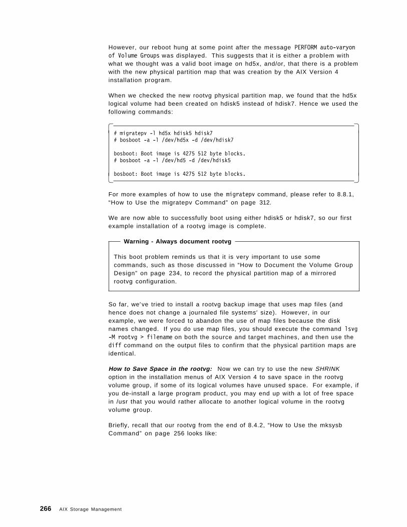
However, our reboot hung at some point after the message PERFORM auto-varyonof Volume Groups was displayed. This suggests that it is either a problem withwhat we thought was a valid boot image on hd5x, and/or, that there is a problemwith the new physical partition map that was creation by the AIX Version 4installation program.
When we checked the new rootvg physical partition map, we found that the hd5xlogical volume had been created on hdisk5 instead of hdisk7. Hence we used thefollowing commands:
� �# migratepv -l hd5x hdisk5 hdisk7# bosboot -a -l /dev/hd5x -d /dev/hdisk7
bosboot: Boot image is 4275 512 byte blocks.# bosboot -a -l /dev/hd5 -d /dev/hdisk5
bosboot: Boot image is 4275 512 byte blocks.� �
For more examples of how to use the migratepv command, please refer to 8.8.1,“How to Use the migratepv Command” on page 312.
We are now able to successfully boot using either hdisk5 or hdisk7, so our firstexample installation of a rootvg image is complete.
Warning - Always document rootvg
This boot problem reminds us that it is very important to use somecommands, such as those discussed in “How to Document the Volume GroupDesign” on page 234, to record the physical partition map of a mirroredrootvg configuration.
So far, we′ve tried to install a rootvg backup image that uses map files (andhence does not change a journaled file systems′ size). However, in ourexample, we were forced to abandon the use of map files because the disknames changed. If you do use map files, you should execute the command lsvg-M rootvg > filename on both the source and target machines, and then use thediff command on the output files to confirm that the physical partition maps areidentical.
How to Save Space in the rootvg: Now we can try to use the new SHRINKoption in the installation menus of AIX Version 4 to save space in the rootvgvolume group, if some of its logical volumes have unused space. For example, ifyou de-install a large program product, you may end up with a lot of free spacein /usr that you would rather allocate to another logical volume in the rootvgvolume group.
Briefly, recall that our rootvg from the end of 8.4.2, “How to Use the mksysbCommand” on page 256 looks like:
266 AIX Storage Management
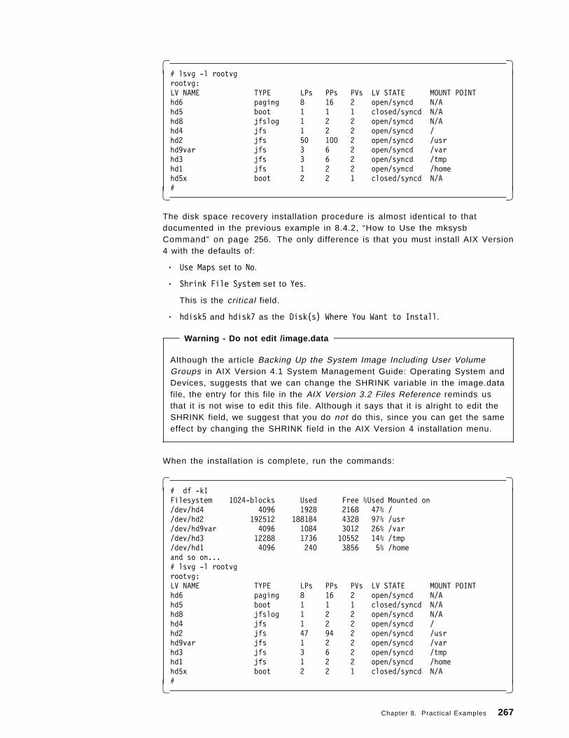
� �# lsvg -l rootvgrootvg:LV NAME TYPE LPs PPs PVs LV STATE MOUNT POINThd6 paging 8 16 2 open/syncd N/Ahd5 boot 1 1 1 closed/syncd N/Ahd8 jfslog 1 2 2 open/syncd N/Ahd4 jfs 1 2 2 open/syncd /hd2 jfs 50 100 2 open/syncd /usrhd9var jfs 3 6 2 open/syncd /varhd3 jfs 3 6 2 open/syncd /tmphd1 jfs 1 2 2 open/syncd /homehd5x boot 2 2 1 closed/syncd N/A#� �
The disk space recovery installation procedure is almost identical to thatdocumented in the previous example in 8.4.2, “How to Use the mksysbCommand” on page 256. The only difference is that you must install AIX Version4 with the defaults of:
• Use Maps set to No.
• Shrink File System set to Yes.
This is the critical field.
• hdisk5 and hdisk7 as the Disk(s) Where You Want to Install.
Warning - Do not edit /image.data
Although the article Backing Up the System Image Including User VolumeGroups in AIX Version 4.1 System Management Guide: Operating System andDevices, suggests that we can change the SHRINK variable in the image.datafile, the entry for this file in the AIX Version 3.2 Files Reference reminds usthat it is not wise to edit this file. Although it says that it is alright to edit theSHRINK field, we suggest that you do not do this, since you can get the sameeffect by changing the SHRINK field in the AIX Version 4 installation menu.
When the installation is complete, run the commands:
� �# df -kIFilesystem 1024-blocks Used Free %Used Mounted on/dev/hd4 4096 1928 2168 47% //dev/hd2 192512 188184 4328 97% /usr/dev/hd9var 4096 1084 3012 26% /var/dev/hd3 12288 1736 10552 14% /tmp/dev/hd1 4096 240 3856 5% /homeand so on...# lsvg -l rootvgrootvg:LV NAME TYPE LPs PPs PVs LV STATE MOUNT POINThd6 paging 8 16 2 open/syncd N/Ahd5 boot 1 1 1 closed/syncd N/Ahd8 jfslog 1 2 2 open/syncd N/Ahd4 jfs 1 2 2 open/syncd /hd2 jfs 47 94 2 open/syncd /usrhd9var jfs 1 2 2 open/syncd /varhd3 jfs 3 6 2 open/syncd /tmphd1 jfs 1 2 2 open/syncd /homehd5x boot 2 2 1 closed/syncd N/A#� �
Chapter 8. Practical Examples 267
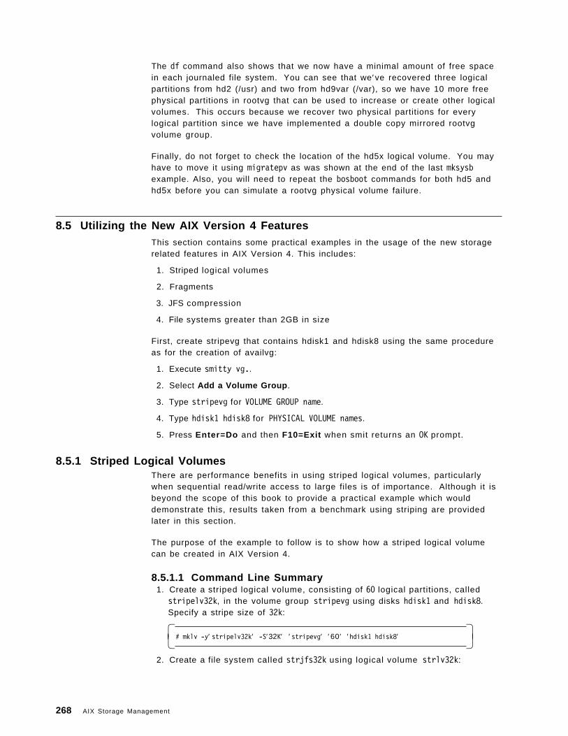
The df command also shows that we now have a minimal amount of free spacein each journaled file system. You can see that we′ve recovered three logicalpartitions from hd2 (/usr) and two from hd9var (/var), so we have 10 more freephysical partitions in rootvg that can be used to increase or create other logicalvolumes. This occurs because we recover two physical partitions for everylogical partition since we have implemented a double copy mirrored rootvgvolume group.
Finally, do not forget to check the location of the hd5x logical volume. You mayhave to move it using migratepv as was shown at the end of the last mksysbexample. Also, you will need to repeat the bosboot commands for both hd5 andhd5x before you can simulate a rootvg physical volume failure.
8.5 Utilizing the New AIX Version 4 FeaturesThis section contains some practical examples in the usage of the new storagerelated features in AIX Version 4. This includes:
1. Striped logical volumes
2. Fragments
3. JFS compression
4. File systems greater than 2GB in size
First, create stripevg that contains hdisk1 and hdisk8 using the same procedureas for the creation of availvg:
1. Execute smitty vg..
2. Select Add a Volume Group .
3. Type stripevg for VOLUME GROUP name.
4. Type hdisk1 hdisk8 for PHYSICAL VOLUME names.
5. Press Enter=Do and then F10=Exit when smit returns an OK prompt.
8.5.1 Striped Logical VolumesThere are performance benefits in using striped logical volumes, particularlywhen sequential read/write access to large files is of importance. Although it isbeyond the scope of this book to provide a practical example which woulddemonstrate this, results taken from a benchmark using striping are providedlater in this section.
The purpose of the example to follow is to show how a striped logical volumecan be created in AIX Version 4.
8.5.1.1 Command Line Summary 1. Create a striped logical volume, consisting of 60 logical partitions, called
stripelv32k, in the volume group stripevg using disks hdisk1 and hdisk8.Specify a stripe size of 32k:
� �# mklv -y′ stripelv32k′ -S′32K′ ′ stripevg′ ′ 60 ′ ′hdisk1 hdisk8′� �
2. Create a file system called strjfs32k using logical volume strlv32k:
268 AIX Storage Management
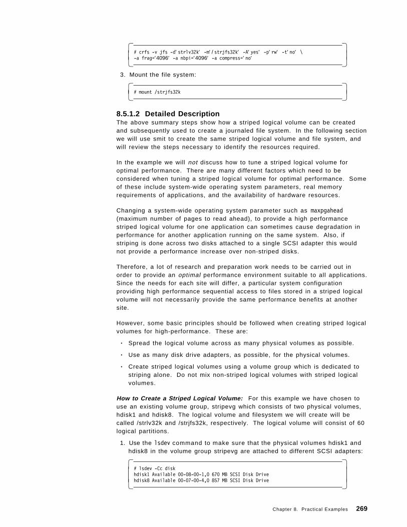
� �# crfs -v jfs -d′ strlv32k′ -m′ / strjfs32k′ -A′ yes′ -p′ rw′ -t′ no′ \-a frag=′4096′ -a nbpi=′4096′ -a compress=′ no′� �
3. Mount the file system:
� �# mount /strjfs32k� �
8.5.1.2 Detailed DescriptionThe above summary steps show how a striped logical volume can be createdand subsequently used to create a journaled file system. In the following sectionwe will use smit to create the same striped logical volume and file system, andwill review the steps necessary to identify the resources required.
In the example we will not discuss how to tune a striped logical volume foroptimal performance. There are many different factors which need to beconsidered when tuning a striped logical volume for optimal performance. Someof these include system-wide operating system parameters, real memoryrequirements of applications, and the availability of hardware resources.
Changing a system-wide operating system parameter such as maxpgahead(maximum number of pages to read ahead), to provide a high performancestriped logical volume for one application can sometimes cause degradation inperformance for another application running on the same system. Also, ifstriping is done across two disks attached to a single SCSI adapter this wouldnot provide a performance increase over non-striped disks.
Therefore, a lot of research and preparation work needs to be carried out inorder to provide an optimal performance environment suitable to all applications.Since the needs for each site will differ, a particular system configurationproviding high performance sequential access to files stored in a striped logicalvolume will not necessarily provide the same performance benefits at anothersite.
However, some basic principles should be followed when creating striped logicalvolumes for high-performance. These are:
• Spread the logical volume across as many physical volumes as possible.
• Use as many disk drive adapters, as possible, for the physical volumes.
• Create striped logical volumes using a volume group which is dedicated tostriping alone. Do not mix non-striped logical volumes with striped logicalvolumes.
How to Create a Striped Logical Volume: For this example we have chosen touse an existing volume group, stripevg which consists of two physical volumes,hdisk1 and hdisk8. The logical volume and filesystem we will create will becalled /strlv32k and /strjfs32k, respectively. The logical volume will consist of 60logical partitions.
1. Use the lsdev command to make sure that the physical volumes hdisk1 andhdisk8 in the volume group stripevg are attached to different SCSI adapters:
� �# lsdev -Cc diskhdisk1 Available 00-08-00-1,0 670 MB SCSI Disk Drivehdisk8 Available 00-07-00-4,0 857 MB SCSI Disk Drive� �
Chapter 8. Practical Examples 269
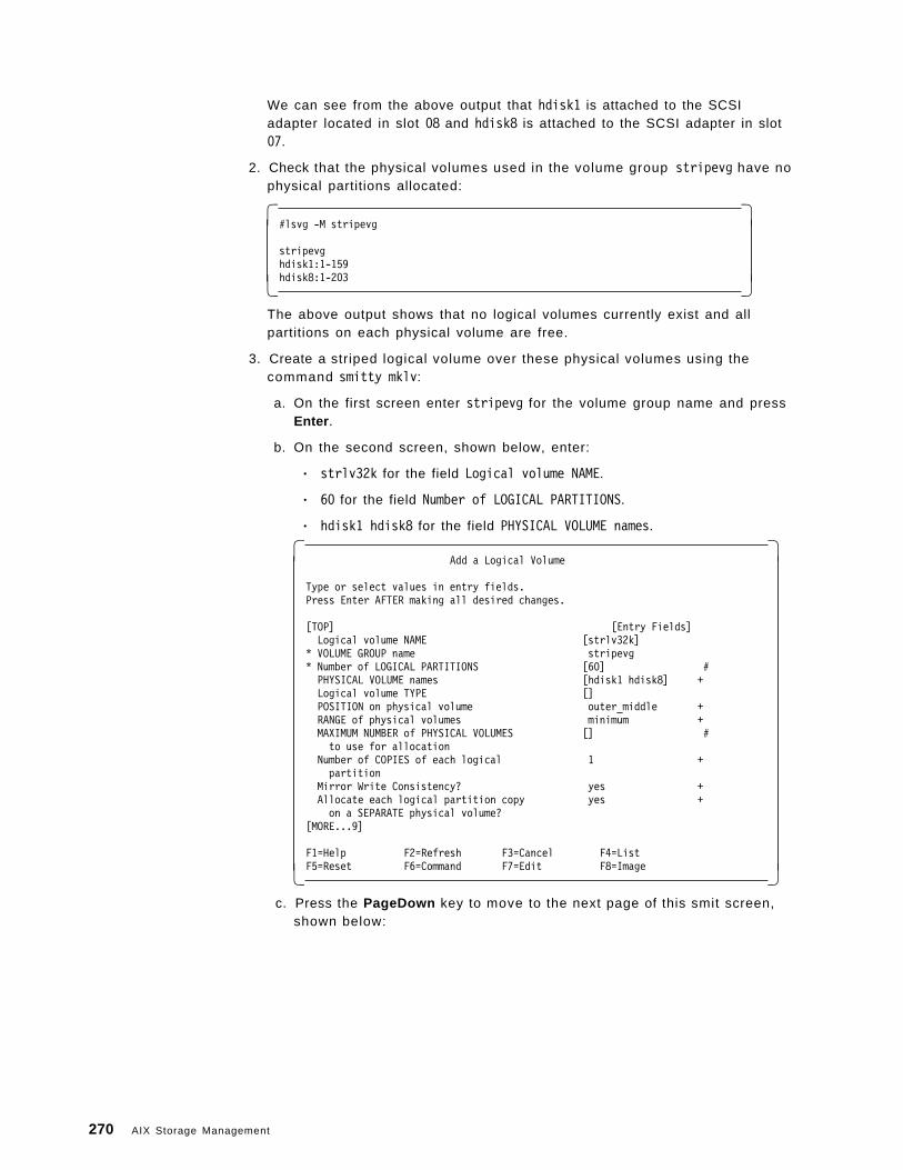
We can see from the above output that hdisk1 is attached to the SCSIadapter located in slot 08 and hdisk8 is attached to the SCSI adapter in slot07.
2. Check that the physical volumes used in the volume group stripevg have nophysical partitions allocated:
� �#lsvg -M stripevg
stripevghdisk1:1-159hdisk8:1-203� �
The above output shows that no logical volumes currently exist and allpartitions on each physical volume are free.
3. Create a striped logical volume over these physical volumes using thecommand smitty mklv:
a. On the first screen enter stripevg for the volume group name and pressEnter .
b. On the second screen, shown below, enter:
• strlv32k for the field Logical volume NAME.
• 60 for the field Number of LOGICAL PARTITIONS.
• hdisk1 hdisk8 for the field PHYSICAL VOLUME names.
� �Add a Logical Volume
Type or select values in entry fields.Press Enter AFTER making all desired changes.
[TOP] [Entry Fields]Logical volume NAME [strlv32k]
* VOLUME GROUP name stripevg* Number of LOGICAL PARTITIONS [60] #PHYSICAL VOLUME names [hdisk1 hdisk8] +Logical volume TYPE []POSITION on physical volume outer_middle +RANGE of physical volumes minimum +MAXIMUM NUMBER of PHYSICAL VOLUMES [] #to use for allocation
Number of COPIES of each logical 1 +partition
Mirror Write Consistency? yes +Allocate each logical partition copy yes +on a SEPARATE physical volume?
[MORE...9]
F1=Help F2=Refresh F3=Cancel F4=ListF5=Reset F6=Command F7=Edit F8=Image� �
c. Press the PageDown key to move to the next page of this smit screen,shown below:
270 AIX Storage Management
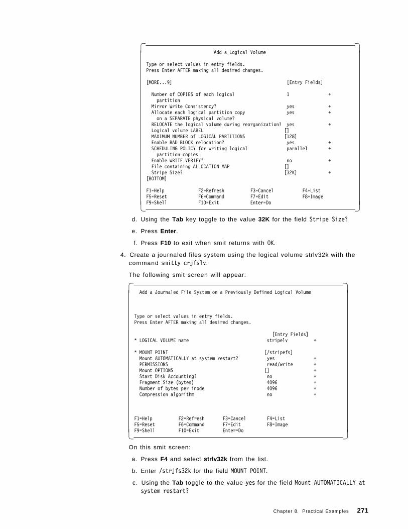
� �Add a Logical Volume
Type or select values in entry fields.Press Enter AFTER making all desired changes.
[MORE...9] [Entry Fields]
Number of COPIES of each logical 1 +partition
Mirror Write Consistency? yes +Allocate each logical partition copy yes +on a SEPARATE physical volume?
RELOCATE the logical volume during reorganization? yes +Logical volume LABEL []MAXIMUM NUMBER of LOGICAL PARTITIONS [128]Enable BAD BLOCK relocation? yes +SCHEDULING POLICY for writing logical parallel +partition copies
Enable WRITE VERIFY? no +File containing ALLOCATION MAP []Stripe Size? [32K] +
[BOTTOM]
F1=Help F2=Refresh F3=Cancel F4=ListF5=Reset F6=Command F7=Edit F8=ImageF9=Shell F10=Exit Enter=Do� �
d. Using the Tab key toggle to the value 32K for the field Stripe Size?
e. Press Enter .
f. Press F10 to exit when smit returns with OK.
4. Create a journaled files system using the logical volume strlv32k with thecommand smitty crjfslv.
The following smit screen will appear:
� �Add a Journaled File System on a Previously Defined Logical Volume
Type or select values in entry fields.Press Enter AFTER making all desired changes.
[Entry Fields]* LOGICAL VOLUME name stripelv +
* MOUNT POINT [/stripefs]Mount AUTOMATICALLY at system restart? yes +PERMISSIONS read/write +Mount OPTIONS [] +Start Disk Accounting? no +Fragment Size (bytes) 4096 +Number of bytes per inode 4096 +Compression algorithm no +
F1=Help F2=Refresh F3=Cancel F4=ListF5=Reset F6=Command F7=Edit F8=ImageF9=Shell F10=Exit Enter=Do� �
On this smit screen:
a. Press F4 and select strlv32k from the list.
b. Enter /strjfs32k for the field MOUNT POINT.
c. Using the Tab toggle to the value yes for the field Mount AUTOMATICALLY atsystem restart?
Chapter 8. Practical Examples 271
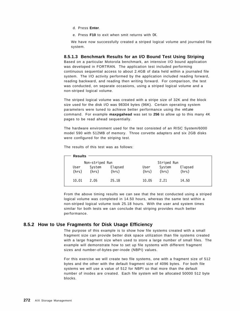
d. Press Enter .
e. Press F10 to exit when smit returns with OK.
We have now successfully created a striped logical volume and journaled filesystem.
8.5.1.3 Benchmark Results for an I/O Bound Test Using StripingBased on a particular Motorola benchmark, an intensive I/O bound applicationwas developed in FORTRAN. The application test included performingcontinuous sequential access to about 2.4GB of data held within a journaled filesystem. The I/O activity performed by the application included reading forward,reading backward, and reading then writing forward. For comparison, the testwas conducted, on separate occasions, using a striped logical volume and anon-striped logical volume.
The striped logical volume was created with a stripe size of 32K and the blocksize used for the disk I/O was 98304 bytes (96K). Certain operating systemparameters were tuned to achieve better performance using the vmtumecommand. For example maxpgahead was set to 256 to allow up to this many 4Kpages to be read ahead sequentially.
The hardware environment used for the test consisted of an RISC System/6000model 590 with 512MB of memory. Three corvette adapters and six 2GB diskswere configured for the striping test.
The results of this test was as follows:
Results
Non-striped Run Striped RunUser System Elapsed User System Elapsed(hrs) (hrs) (hrs) (hrs) (hrs) (hrs)
10.01 2.05 25.18 10.05 2.21 14.50
From the above timing results we can see that the test conducted using a stripedlogical volume was completed in 14.50 hours, whereas the same test within anon-striped logical volume took 25.18 hours. With the user and system timessimilar for both tests we can conclude that striping provides much betterperformance.
8.5.2 How to Use Fragments for Disk Usage EfficiencyThe purpose of this example is to show how file systems created with a smallfragment size can provide better disk space utilization than file systems createdwith a large fragment size when used to store a large number of small files. Theexample will demonstrate how to set up file systems with different fragmentsizes and number-of-bytes-per-inode (NBPI) values.
For this exercise we will create two file systems, one with a fragment size of 512bytes and the other with the default fragment size of 4096 bytes. For both filesystems we will use a value of 512 for NBPI so that more than the defaultnumber of inodes are created. Each file system will be allocated 50000 512 byteblocks.
272 AIX Storage Management
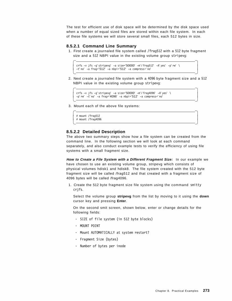
The test for efficient use of disk space will be determined by the disk space usedwhen a number of equal sized files are stored within each file system. In eachof these file systems we will store several small files, each 512 bytes in size.
8.5.2.1 Command Line Summary 1. First create a journaled file system called /frag512 with a 512 byte fragment
size and a 512 NBPI value in the existing volume group stripevg:
� �crfs -v jfs -g′ stripevg′ -a size=′50000′ -m′ / frag512′ -A′ yes′ -p′ rw′ \-t′ no′ -a frag=′512′ -a nbpi=′512′ -a compress=′ no′� �
2. Next create a journaled file system with a 4096 byte fragment size and a 512NBPI value in the existing volume group stripevg:
� �crfs -v jfs -g′ stripevg′ -a size=′50000′ -m′ / frag4096′ -A′ yes′ \-p′ rw′ -t′ no′ -a frag=′4096′ -a nbpi=′512′ -a compress=′ no′� �
3. Mount each of the above file systems:
� �# mount /frag512# mount /frag4096� �
8.5.2.2 Detailed DescriptionThe above two summary steps show how a file system can be created from thecommand line. In the following section we will look at each commandseparately, and also conduct example tests to verify the efficiency of using filesystems with a small fragment size.
How to Create a File System with a Different Fragment Size: In our example wehave chosen to use an existing volume group, stripevg which consists ofphysical volumes hdisk1 and hdisk8. The file system created with the 512 bytefragment size will be called /frag512 and that created with a fragment size of4096 bytes will be called /frag4096.
1. Create the 512 byte fragment size file system using the command smittycrjfs.
Select the volume group stripevg from the list by moving to it using the downcursor key and pressing Enter .
On the second smit screen, shown below, enter or change details for thefollowing fields:
• SIZE of file system (in 512 byte blocks)
• MOUNT POINT
• Mount AUTOMATICALLY at system restart?
• Fragment Size (bytes)
• Number of bytes per inode
Chapter 8. Practical Examples 273
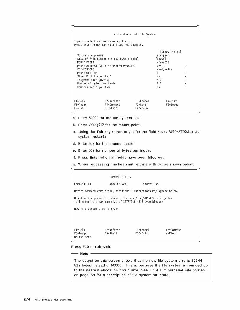
� �Add a Journaled File System
Type or select values in entry fields.Press Enter AFTER making all desired changes.
[Entry Fields]Volume group name stripevg
* SIZE of file system (in 512-byte blocks) [50000]* MOUNT POINT [/frag512]Mount AUTOMATICALLY at system restart? yes +PERMISSIONS read/write +Mount OPTIONS [] +Start Disk Accounting? no +Fragment Size (bytes) 512 +Number of bytes per inode 512 +Compression algorithm no +
F1=Help F2=Refresh F3=Cancel F4=ListF5=Reset F6=Command F7=Edit F8=ImageF9=Shell F10=Exit Enter=Do� �
a. Enter 50000 for the file system size.
b. Enter /frag512 for the mount point.
c. Using the Tab key rotate to yes for the field Mount AUTOMATICALLY atsystem restart?
d. Enter 512 for the fragment size.
e. Enter 512 for number of bytes per inode.
f. Press Enter when all fields have been filled out.
g. When processing finishes smit returns with OK, as shown below:
� �COMMAND STATUS
Command: OK stdout: yes stderr: no
Before command completion, additional instructions may appear below.
Based on the parameters chosen, the new /frag512 JFS file systemis limited to a maximum size of 16777216 (512 byte blocks)
New File System size is 57344
F1=Help F2=Refresh F3=Cancel F6=CommandF8=Image F9=Shell F10=Exit /=Findn=Find Next� �
Press F10 to exit smit.
Note
The output on this screen shows that the new file system size is 57344512 bytes instead of 50000. This is because the file system is rounded upto the nearest allocation group size. See 3.1.4.1, “Journaled File System”on page 59 for a description of file system structure.
274 AIX Storage Management
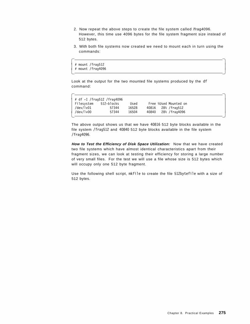
2. Now repeat the above steps to create the file system called /frag4096.However, this time use 4096 bytes for the file system fragment size instead of512 bytes.
3. With both file systems now created we need to mount each in turn using thecommands:
� �# mount /frag512# mount /frag4096� �
Look at the output for the two mounted file systems produced by the dfcommand:
� �# df -I /frag512 /frag4096Filesystem 512-blocks Used Free %Used Mounted on/dev/lv01 57344 16528 40816 28% /frag512/dev/lv00 57344 16504 40840 28% /frag4096� �
The above output shows us that we have 40816 512 byte blocks available in thefile system /frag512 and 40840 512 byte blocks available in the file system/frag4096.
How to Test the Efficiency of Disk Space Utilization: Now that we have createdtwo file systems which have almost identical characteristics apart from theirfragment sizes, we can look at testing their efficiency for storing a large numberof very small files. For the test we will use a file whose size is 512 bytes whichwill occupy only one 512 byte fragment.
Use the following shell script, mkfile to create the file 512bytefile with a size of512 bytes.
Chapter 8. Practical Examples 275
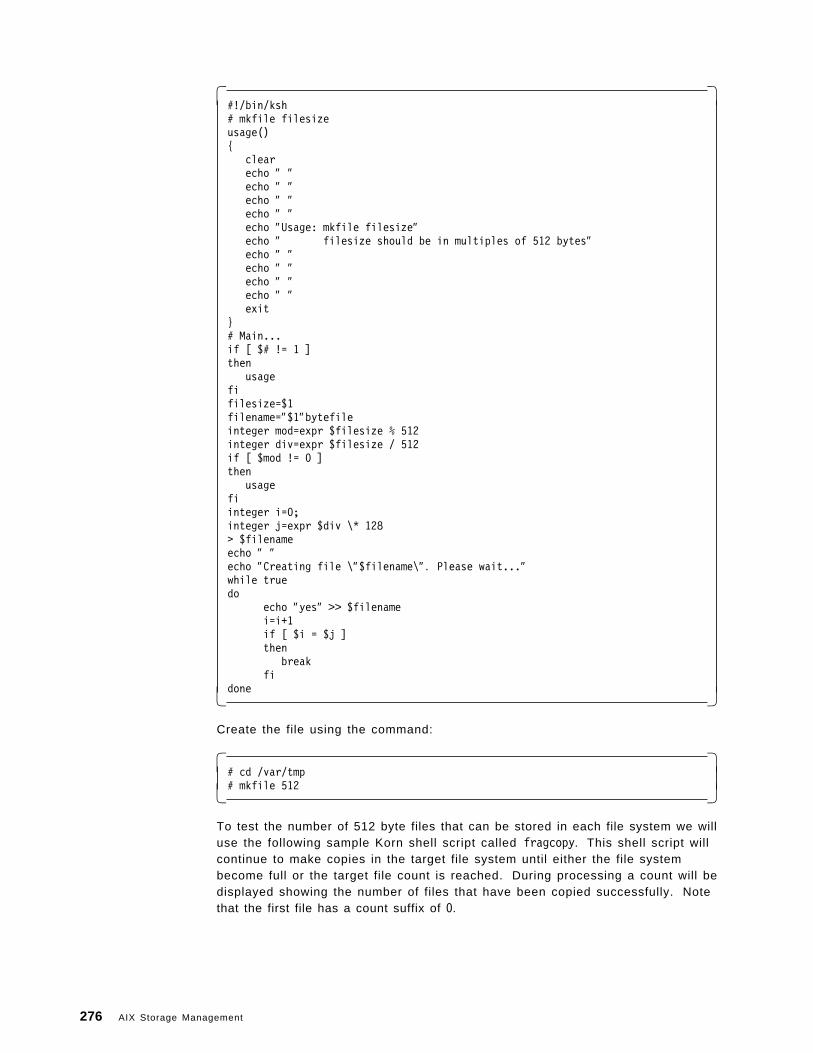
� �#!/bin/ksh# mkfile filesizeusage(){
clearecho ″ ″echo ″ ″echo ″ ″echo ″ ″echo ″Usage: mkfile filesize″echo ″ filesize should be in multiples of 512 bytes″echo ″ ″echo ″ ″echo ″ ″echo ″ ″exit
}# Main...if [ $# != 1 ]then
usagefifilesize=$1filename=″$1″bytefileinteger mod=expr $filesize % 512integer div=expr $filesize / 512if [ $mod != 0 ]then
usagefiinteger i=0;integer j=expr $div \* 128> $filenameecho ″ ″echo ″Creating file \″$filename\″ . Please wait...″while truedo
echo ″yes″ >> $filenamei=i+1if [ $i = $j ]then
breakfi
done� �
Create the file using the command:
� �# cd /var/tmp# mkfile 512� �
To test the number of 512 byte files that can be stored in each file system we willuse the following sample Korn shell script called fragcopy. This shell script willcontinue to make copies in the target file system until either the file systembecome full or the target file count is reached. During processing a count will bedisplayed showing the number of files that have been copied successfully. Notethat the first file has a count suffix of 0.
276 AIX Storage Management
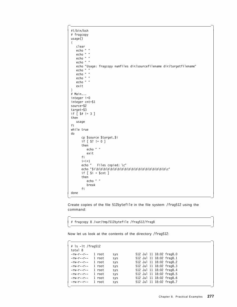
� �#!/bin/ksh# fragcopyusage(){
clearecho ″ ″echo ″ ″echo ″ ″echo ″ ″echo ″Usage: fragcopy numfiles dir/sourcefilename dir/targetfilename″echo ″ ″echo ″ ″echo ″ ″echo ″ ″exit
}# Main...integer i=0integer cnt=$1source=$2target=$3if [ $# != 3 ]then
usagefiwhile truedo
cp $source $target.$iif [ $? != 0 ]then
echo ″ ″exit
fii=i+1echo ″ Files copied: \c″echo ″$i\b\b\b\b\b\b\b\b\b\b\b\b\b\b\b\b\b\b\b\b\c″if [ $i = $cnt ]then
echo ″ ″break
fidone� �
Create copies of the file 512bytefile in the file system /frag512 using thecommand:
� �# fragcopy 8 /var/tmp/512bytefile /frag512/frag8� �
Now let us look at the contents of the directory /frag512:
� �# ls -lt /frag512total 8-rw-r--r-- 1 root sys 512 Jul 11 18:02 frag8.0-rw-r--r-- 1 root sys 512 Jul 11 18:02 frag8.1-rw-r--r-- 1 root sys 512 Jul 11 18:02 frag8.2-rw-r--r-- 1 root sys 512 Jul 11 18:02 frag8.3-rw-r--r-- 1 root sys 512 Jul 11 18:02 frag8.4-rw-r--r-- 1 root sys 512 Jul 11 18:02 frag8.5-rw-r--r-- 1 root sys 512 Jul 11 18:02 frag8.6-rw-r--r-- 1 root sys 512 Jul 11 18:02 frag8.7� �
Chapter 8. Practical Examples 277
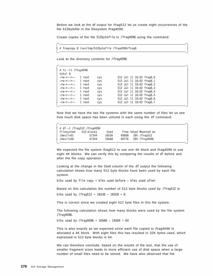
Before we look at the df output for /frag512 let us create eight occurrences of thefile 512bytefile in the filesystem /frag4096.
Create copies of the file 512bytefile in /frag4096 using the command:
� �# fragcopy 8 /var/tmp/512bytefile /frag4096/frag8� �
Look at the directory contents for /frag4096:
� �# ls -lt /frag4096total 8-rw-r--r-- 1 root sys 512 Jul 11 18:02 frag8.0-rw-r--r-- 1 root sys 512 Jul 11 18:02 frag8.1-rw-r--r-- 1 root sys 512 Jul 11 18:02 frag8.2-rw-r--r-- 1 root sys 512 Jul 11 18:02 frag8.3-rw-r--r-- 1 root sys 512 Jul 11 18:02 frag8.4-rw-r--r-- 1 root sys 512 Jul 11 18:02 frag8.5-rw-r--r-- 1 root sys 512 Jul 11 18:02 frag8.6-rw-r--r-- 1 root sys 512 Jul 11 18:02 frag8.7� �
Now that we have the two file systems with the same number of files let us seehow much disk space has been utilized in each using the df command:
� �# df -I /frag512 /frag4096Filesystem 512-blocks Used Free %Used Mounted on/dev/lv01 57344 16536 40808 28% /frag512/dev/lv00 57344 16568 40776 28% /frag4096� �
We expected the file system /frag512 to use one 4K block and /frag4096 to useeight 4K blocks. We can verify this by comparing the results of df before andafter the file copy operation.
Looking at the change in the Used column of the df output the followingcalculation shows how many 512 byte blocks have been used by each filesystem:
blks used by file copy = blks used before - blks used after
Based on this calculation the number of 512 byte blocks used by /frag512 is:
blks used by /frag512 = 16536 - 16528 = 8
This is correct since we created eight 512 byte files in this file system.
The following calculation shows how many blocks were used by the file system/frag4096.
blks used by /frag4096 = 16568 - 16504 = 64
This is also exactly as we expected since each file copied to /frag4096 isallocated a 4K block. With eight files this has resulted in 32K bytes used, whichexpressed in 512 byte blocks is 64.
We can therefore conclude, based on the results of the test, that the use ofsmaller fragment sizes leads to more efficient use of disk space when a largenumber of small files need to be stored. We have also observed that file
278 AIX Storage Management
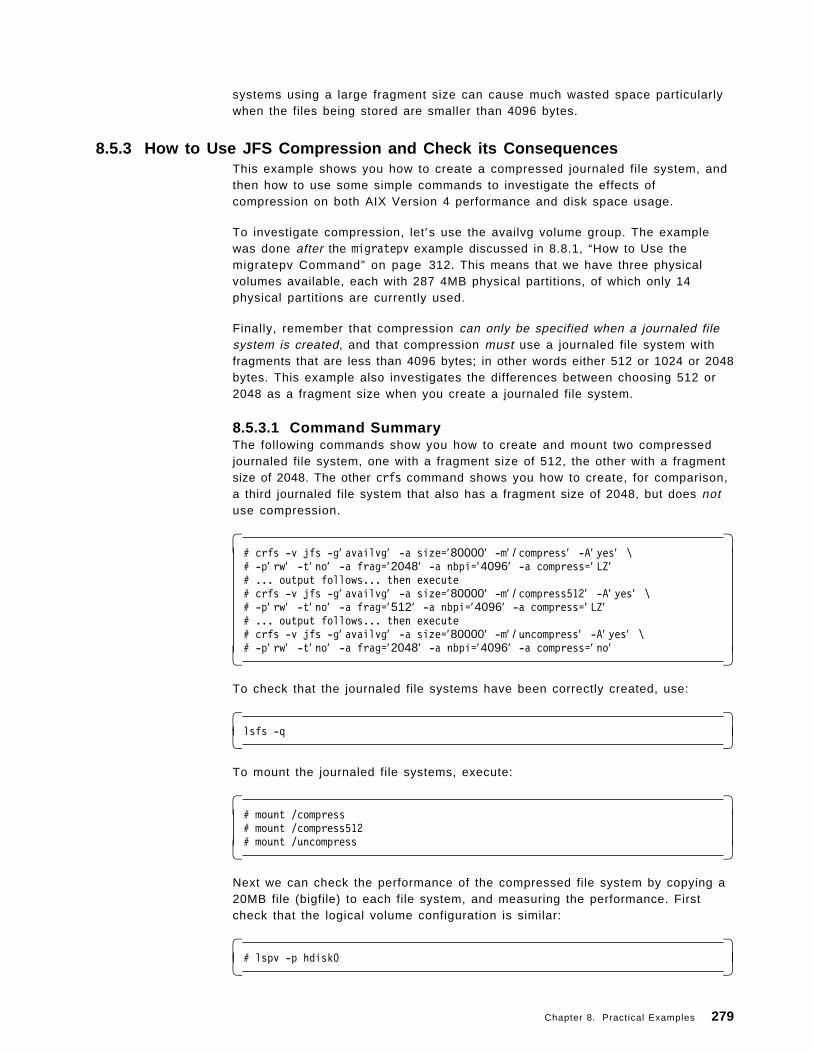
systems using a large fragment size can cause much wasted space particularlywhen the files being stored are smaller than 4096 bytes.
8.5.3 How to Use JFS Compression and Check its ConsequencesThis example shows you how to create a compressed journaled file system, andthen how to use some simple commands to investigate the effects ofcompression on both AIX Version 4 performance and disk space usage.
To investigate compression, let′s use the availvg volume group. The examplewas done after the migratepv example discussed in 8.8.1, “How to Use themigratepv Command” on page 312. This means that we have three physicalvolumes available, each with 287 4MB physical partitions, of which only 14physical partitions are currently used.
Finally, remember that compression can only be specified when a journaled filesystem is created, and that compression must use a journaled file system withfragments that are less than 4096 bytes; in other words either 512 or 1024 or 2048bytes. This example also investigates the differences between choosing 512 or2048 as a fragment size when you create a journaled file system.
8.5.3.1 Command SummaryThe following commands show you how to create and mount two compressedjournaled file system, one with a fragment size of 512, the other with a fragmentsize of 2048. The other crfs command shows you how to create, for comparison,a third journaled file system that also has a fragment size of 2048, but does notuse compression.
� �# crfs -v jfs -g′ availvg′ -a size=′80000′ -m′ / compress′ -A′ yes′ \# -p′ rw′ -t′ no′ -a frag=′2048′ -a nbpi=′4096′ -a compress=′ LZ′# ... output follows... then execute# crfs -v jfs -g′ availvg′ -a size=′80000′ -m′ / compress512′ -A′ yes′ \# -p′ rw′ -t′ no′ -a frag=′512′ -a nbpi=′4096′ -a compress=′ LZ′# ... output follows... then execute# crfs -v jfs -g′ availvg′ -a size=′80000′ -m′ / uncompress′ -A′ yes′ \# -p′ rw′ -t′ no′ -a frag=′2048′ -a nbpi=′4096′ -a compress=′ no′� �
To check that the journaled file systems have been correctly created, use:
� �lsfs -q� �
To mount the journaled file systems, execute:
� �# mount /compress# mount /compress512# mount /uncompress� �
Next we can check the performance of the compressed file system by copying a20MB file (bigfile) to each file system, and measuring the performance. Firstcheck that the logical volume configuration is similar:
� �# lspv -p hdisk0� �
Chapter 8. Practical Examples 279
Now record copy times:
� �# timex cp /strjfs16k/bigfile /compress# timex cp /strjfs16k/bigfile /uncompress# timex cp /strjfs16k/bigfile /compress512� �
Finally, check that all files are the same size:
� �# ls -lt /compress /uncompress /strjfs16k� �
Lastly, we can check the disk utilization in order to investigate the efficiency ofthe compression. Copy the following 2560 byte files:
� �# cp /strjfs32k/fragdata/2560bytefile /compress512/2560bytefile# cp /strjfs32k/fragdata/2560bytefile /compress/2560bytefile# cp /strjfs32k/fragdata/2560bytefile /uncompress/2560bytefile# cp /strjfs32k/fragdata/2560bytefile /frag512/2560bytefile� �
Use du to check much space is really used:
� �# du /strjfs32k/fragdata/2560bytefile# du /compress512/2560bytefile# du /compress/2560bytefile# du /uncompress/2560bytefile# du /frag512/2560bytefile� �
Use ls to verify the normal size of each file:
� �# ls -l /strjfs32k/fragdata/2560bytefile /frag512/2560bytefile# ls -l /compress512/2560bytefile /compress/2560bytefile# ls -l /uncompress/2560bytefile� �
8.5.3.2 Detailed GuidanceHow to Create a Compressed JFS: Since the availvg volume group has plenty offree space and one totally empty disk after the migration in 8.8.1, “How to Usethe migratepv Command” on page 312, then in this case we can create thejournaled file system straight away, without first creating a target logical volumefor the journaled file system. As you can see later in this section, the logicalvolume manager in this case uses a physical partition map for the journaled filesystems in this example that does not have a significant effect on ourperformance results, which are discussed in “How to Check the Performance ofa Compressed File System” on page 285.
Although we want to create three journaled file systems for this example, themethod is almost identical with only a few fields that are different. Hence smitmenus are only provided once.
To create a 40MB compressed journaled file system with a fragment size of 2048bytes mounted at /compress:
1. Execute the fastpath smitty crjfs to get to the following volume group menuselection:
280 AIX Storage Management
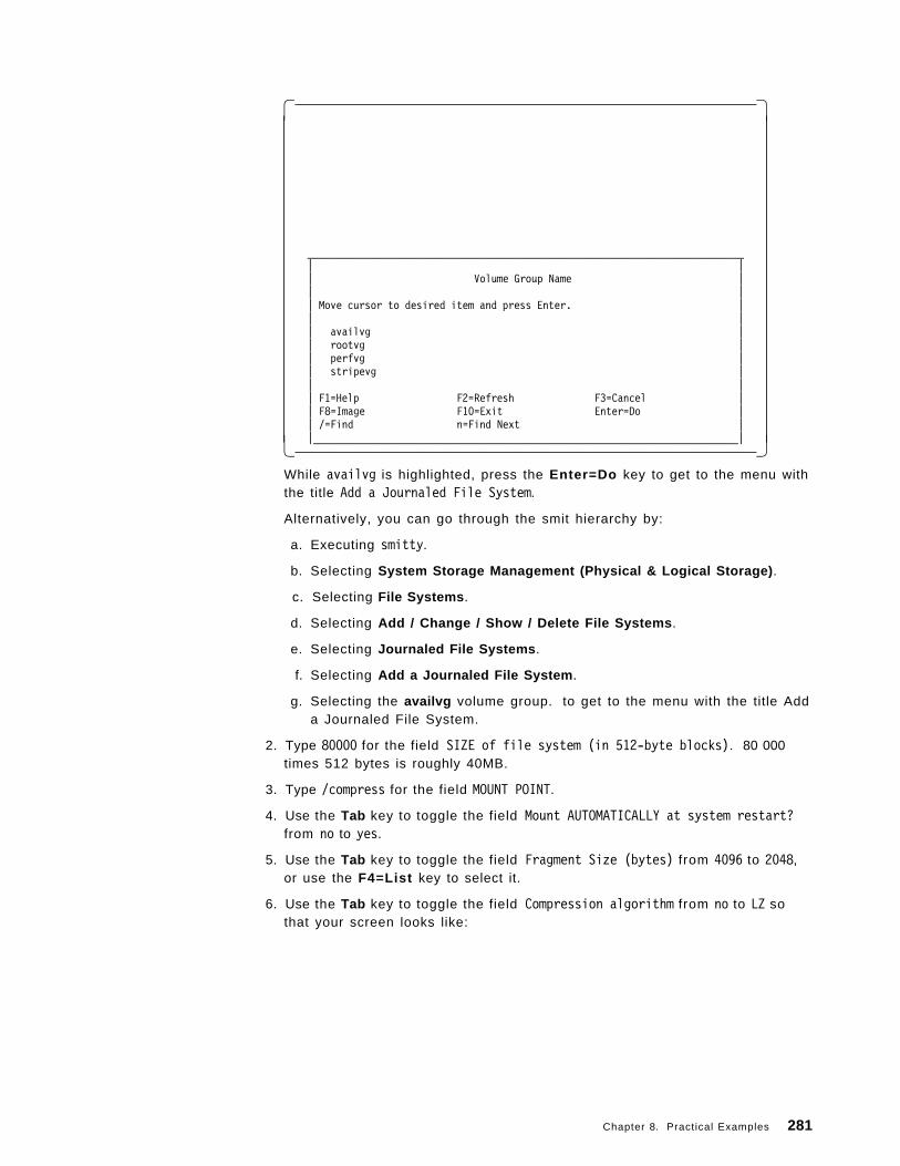
� �
____________________________________________________________________________| || Volume Group Name || || Move cursor to desired item and press Enter. || || availvg || rootvg || perfvg || stripevg || || F1=Help F2=Refresh F3=Cancel || F8=Image F10=Exit Enter=Do || /=Find n=Find Next ||__________________________________________________________________________|� �
While availvg is highlighted, press the Enter=Do key to get to the menu withthe title Add a Journaled File System.
Alternatively, you can go through the smit hierarchy by:
a. Executing smitty.
b. Selecting System Storage Management (Physical & Logical Storage) .
c. Selecting File Systems .
d. Selecting Add / Change / Show / Delete File Systems .
e. Selecting Journaled File Systems .
f. Selecting Add a Journaled File System .
g. Selecting the availvg volume group. to get to the menu with the title Adda Journaled File System.
2. Type 80000 for the field SIZE of file system (in 512-byte blocks). 80 000times 512 bytes is roughly 40MB.
3. Type /compress for the field MOUNT POINT.
4. Use the Tab key to toggle the field Mount AUTOMATICALLY at system restart?from no to yes.
5. Use the Tab key to toggle the field Fragment Size (bytes) from 4096 to 2048,or use the F4=List key to select it.
6. Use the Tab key to toggle the field Compression algorithm from no to LZ sothat your screen looks like:
Chapter 8. Practical Examples 281
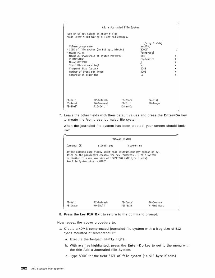
� �Add a Journaled File System
Type or select values in entry fields.Press Enter AFTER making all desired changes.
[Entry Fields]Volume group name availvg
* SIZE of file system (in 512-byte blocks) [80000] #* MOUNT POINT [/compress]Mount AUTOMATICALLY at system restart? yes +PERMISSIONS read/write +Mount OPTIONS [] +Start Disk Accounting? no +Fragment Size (bytes) 2048 +Number of bytes per inode 4096 +Compression algorithm LZ +
F1=Help F2=Refresh F3=Cancel F4=ListF5=Reset F6=Command F7=Edit F8=ImageF9=Shell F10=Exit Enter=Do� �
7. Leave the other fields with their default values and press the Enter=Do keyto create the /compress journaled file system.
When the journaled file system has been created, your screen should looklike:
� �COMMAND STATUS
Command: OK stdout: yes stderr: no
Before command completion, additional instructions may appear below.Based on the parameters chosen, the new /compress JFS file systemis limited to a maximum size of 134217728 (512 byte blocks)New File System size is 81920
F1=Help F2=Refresh F3=Cancel F6=CommandF8=Image F9=Shell F10=Exit /=Find Next� �
8. Press the key F10=Exit to return to the command prompt.
Now repeat the above procedure to:
1. Create a 40MB compressed journaled file system with a frag size of 512bytes mounted at /compress512:
a. Execute the fastpath smitty crjfs.
b. With availvg highlighted, press the Enter=Do key to get to the menu withthe title Add a Journaled File System.
c. Type 80000 for the field SIZE of file system (in 512-byte blocks).
282 AIX Storage Management
d. Type /compress512 for the field MOUNT POINT.
e. Use the Tab key to toggle the field Mount AUTOMATICALLY at systemrestart? from no to yes.
f. Use the Tab key to toggle the field Fragment Size (bytes) from 4096 to512, or use the F4=List key to select it.
g. Use the Tab key to toggle the field Compression algorithm from no to LZ.
h. Leave the other fields with their default values and press the Enter=Dokey to create the /compress512 journaled file system.
i. Press the key F10=Exit to return to the command prompt.
2. Create a 40MB non-compressed journaled file system with a fragment size of2048 bytes mounted at /uncompress:
a. Execute the fastpath smitty crjfs.
b. With availvg highlighted, press the Enter=Do key to get to the menu withthe title Add a Journaled File System.
c. Type 80000 for the field SIZE of file system (in 512-byte blocks).
d. Type /uncompress for the field MOUNT POINT.
e. Use the Tab key to toggle the field Mount AUTOMATICALLY at systemrestart? from no to yes.
f. Use the Tab key to toggle the field Fragment Size (bytes) from 4096 to2048, or use the F4=List key to select it.
g. Do not change the field Compression algorithm; leave it with the defaultsetting of no.
h. Leave the other fields with their default values and press the Enter=Dokey to create the /uncompress journaled file system.
i. Press the key F10=Exit to return to the command prompt.
How to Check the Characteristics of the New JFS: We could use smit to checkthe characteristics of each individual journaled file system by using the fastpathsmitty chjfs and selecting, for example, /compress . To view a summary for allthe journaled file systems, we could also:
1. Execute smitty fs to get to the File Systems menu.
2. Select List All File Systems to execute the command lsfs.
However, the flag -q now also tells us about the new AIX Version 4 journaled filesystem attributes, so the best way to check our new journaled file systems is toexecute:
Chapter 8. Practical Examples 283
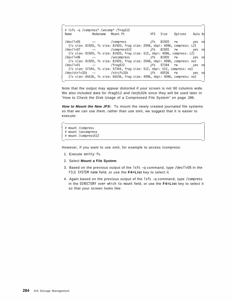
� �# lsfs -q /compress* /uncomp* /frag512Name Nodename Mount Pt VFS Size Options Auto Ac
/dev/lv05 -- /compress jfs 81920 rw yes no(lv size: 81920, fs size: 81920, frag size: 2048, nbpi: 4096, compress: LZ)
/dev/lv07 -- /compress512 jfs 81920 rw yes no(lv size: 81920, fs size: 81920, frag size: 512, nbpi: 4096, compress: LZ)
/dev/lv06 -- /uncompress jfs 81920 rw yes no(lv size: 81920, fs size: 81920, frag size: 2048, nbpi: 4096, compress: no)
/dev/lv01 -- /frag512 jfs 57344 rw yes no(lv size: 57344, fs size: 57344, frag size: 512, nbpi: 512, compress: no)
/dev/strlv32k -- /strjfs32k jfs 65536 rw yes no(lv size: 65536, fs size: 65536, frag size: 4096, nbpi: 4096, compress: no)� �
Note that the output may appear distorted if your screen is not 90 columns wide.We also included data for /frag512 and /strjfs32k since they will be used later in“How to Check the Disk Usage of a Compressed File System” on page 286.
How to Mount the New JFS: To mount the newly created journaled file systemsso that we can use them, rather than use smit, we suggest that it is easier toexecute:
� �# mount /compress# mount /uncompress# mount /compress512� �
However, if you want to use smit, for example to access /compress:
1. Execute smitty fs.
2. Select Mount a File System .
3. Based on the previous output of the lsfs -q command, type /dev/lv05 in theFILE SYSTEM name field, or use the F4=List key to select it.
4. Again based on the previous output of the lsfs -q command, type /compressin the DIRECTORY over which to mount field, or use the F4=List key to select itso that your screen looks like:
284 AIX Storage Management
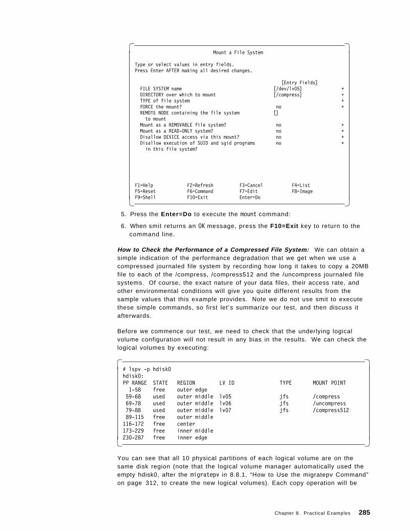
� �Mount a File System
Type or select values in entry fields.Press Enter AFTER making all desired changes.
[Entry Fields]FILE SYSTEM name [/dev/lv05] +DIRECTORY over which to mount [/compress] +TYPE of file system +FORCE the mount? no +REMOTE NODE containing the file system []to mount
Mount as a REMOVABLE file system? no +Mount as a READ-ONLY system? no +Disallow DEVICE access via this mount? no +Disallow execution of SUID and sgid programs no +in this file system?
F1=Help F2=Refresh F3=Cancel F4=ListF5=Reset F6=Command F7=Edit F8=ImageF9=Shell F10=Exit Enter=Do� �
5. Press the Enter=Do to execute the mount command:
6. When smit returns an OK message, press the F10=Exit key to return to thecommand line.
How to Check the Performance of a Compressed File System: We can obtain asimple indication of the performance degradation that we get when we use acompressed journaled file system by recording how long it takes to copy a 20MBfile to each of the /compress, /compress512 and the /uncompress journaled filesystems. Of course, the exact nature of your data files, their access rate, andother environmental conditions will give you quite different results from thesample values that this example provides. Note we do not use smit to executethese simple commands, so first let′s summarize our test, and then discuss itafterwards.
Before we commence our test, we need to check that the underlying logicalvolume configuration will not result in any bias in the results. We can check thelogical volumes by executing:
� �# lspv -p hdisk0hdisk0:PP RANGE STATE REGION LV ID TYPE MOUNT POINT1-58 free outer edge59-68 used outer middle lv05 jfs /compress69-78 used outer middle lv06 jfs /uncompress79-88 used outer middle lv07 jfs /compress51289-115 free outer middle116-172 free center173-229 free inner middle230-287 free inner edge� �
You can see that all 10 physical partitions of each logical volume are on thesame disk region (note that the logical volume manager automatically used theempty hdisk0, after the migratepv in 8.8.1, “How to Use the migratepv Command”on page 312, to create the new logical volumes). Each copy operation will be
Chapter 8. Practical Examples 285
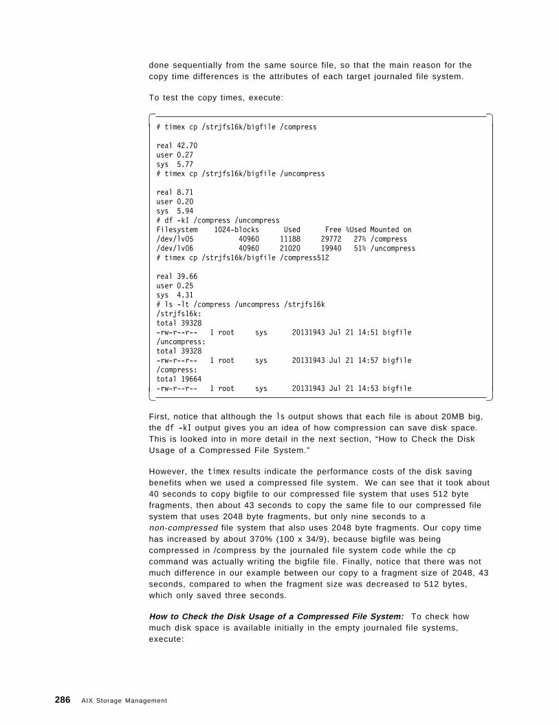
done sequentially from the same source file, so that the main reason for thecopy time differences is the attributes of each target journaled file system.
To test the copy times, execute:
� �# timex cp /strjfs16k/bigfile /compress
real 42.70user 0.27sys 5.77# timex cp /strjfs16k/bigfile /uncompress
real 8.71user 0.20sys 5.94# df -kI /compress /uncompressFilesystem 1024-blocks Used Free %Used Mounted on/dev/lv05 40960 11188 29772 27% /compress/dev/lv06 40960 21020 19940 51% /uncompress# timex cp /strjfs16k/bigfile /compress512
real 39.66user 0.25sys 4.31# ls -lt /compress /uncompress /strjfs16k/strjfs16k:total 39328-rw-r--r-- 1 root sys 20131943 Jul 21 14:51 bigfile/uncompress:total 39328-rw-r--r-- 1 root sys 20131943 Jul 21 14:57 bigfile/compress:total 19664-rw-r--r-- 1 root sys 20131943 Jul 21 14:53 bigfile� �
First, notice that although the ls output shows that each file is about 20MB big,the df -kI output gives you an idea of how compression can save disk space.This is looked into in more detail in the next section, “How to Check the DiskUsage of a Compressed File System.”
However, the timex results indicate the performance costs of the disk savingbenefits when we used a compressed file system. We can see that it took about40 seconds to copy bigfile to our compressed file system that uses 512 bytefragments, then about 43 seconds to copy the same file to our compressed filesystem that uses 2048 byte fragments, but only nine seconds to anon-compressed file system that also uses 2048 byte fragments. Our copy timehas increased by about 370% (100 x 34/9), because bigfile was beingcompressed in /compress by the journaled file system code while the cpcommand was actually writing the bigfile file. Finally, notice that there was notmuch difference in our example between our copy to a fragment size of 2048, 43seconds, compared to when the fragment size was decreased to 512 bytes,which only saved three seconds.
How to Check the Disk Usage of a Compressed File System: To check howmuch disk space is available initially in the empty journaled file systems,execute:
286 AIX Storage Management
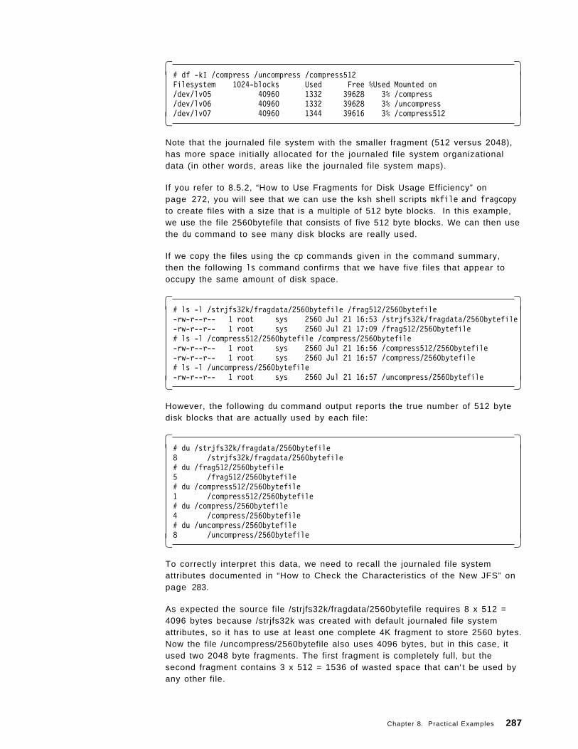
� �# df -kI /compress /uncompress /compress512Filesystem 1024-blocks Used Free %Used Mounted on/dev/lv05 40960 1332 39628 3% /compress/dev/lv06 40960 1332 39628 3% /uncompress/dev/lv07 40960 1344 39616 3% /compress512� �
Note that the journaled file system with the smaller fragment (512 versus 2048),has more space initially allocated for the journaled file system organizationaldata (in other words, areas like the journaled file system maps).
If you refer to 8.5.2, “How to Use Fragments for Disk Usage Efficiency” onpage 272, you will see that we can use the ksh shell scripts mkfile and fragcopyto create files with a size that is a multiple of 512 byte blocks. In this example,we use the file 2560bytefile that consists of five 512 byte blocks. We can then usethe du command to see many disk blocks are really used.
If we copy the files using the cp commands given in the command summary,then the following ls command confirms that we have five files that appear tooccupy the same amount of disk space.
� �# ls -l /strjfs32k/fragdata/2560bytefile /frag512/2560bytefile-rw-r--r-- 1 root sys 2560 Jul 21 16:53 /strjfs32k/fragdata/2560bytefile-rw-r--r-- 1 root sys 2560 Jul 21 17:09 /frag512/2560bytefile# ls -l /compress512/2560bytefile /compress/2560bytefile-rw-r--r-- 1 root sys 2560 Jul 21 16:56 /compress512/2560bytefile-rw-r--r-- 1 root sys 2560 Jul 21 16:57 /compress/2560bytefile# ls -l /uncompress/2560bytefile-rw-r--r-- 1 root sys 2560 Jul 21 16:57 /uncompress/2560bytefile� �
However, the following du command output reports the true number of 512 bytedisk blocks that are actually used by each file:
� �# du /strjfs32k/fragdata/2560bytefile8 /strjfs32k/fragdata/2560bytefile# du /frag512/2560bytefile5 /frag512/2560bytefile# du /compress512/2560bytefile1 /compress512/2560bytefile# du /compress/2560bytefile4 /compress/2560bytefile# du /uncompress/2560bytefile8 /uncompress/2560bytefile� �
To correctly interpret this data, we need to recall the journaled file systemattributes documented in “How to Check the Characteristics of the New JFS” onpage 283.
As expected the source file /strjfs32k/fragdata/2560bytefile requires 8 x 512 =4096 bytes because /strjfs32k was created with default journaled file systemattributes, so it has to use at least one complete 4K fragment to store 2560 bytes.Now the file /uncompress/2560bytefile also uses 4096 bytes, but in this case, itused two 2048 byte fragments. The first fragment is completely full, but thesecond fragment contains 3 x 512 = 1536 of wasted space that can′ t be used byany other file.
Chapter 8. Practical Examples 287
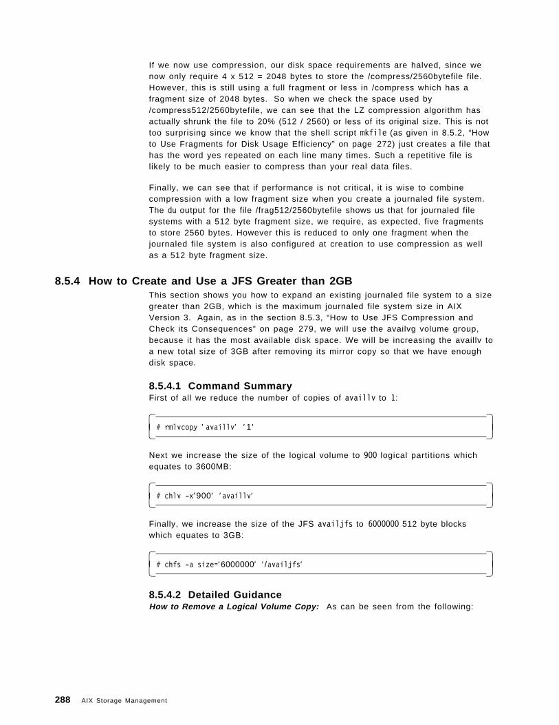
If we now use compression, our disk space requirements are halved, since wenow only require 4 x 512 = 2048 bytes to store the /compress/2560bytefile file.However, this is still using a full fragment or less in /compress which has afragment size of 2048 bytes. So when we check the space used by/compress512/2560bytefile, we can see that the LZ compression algorithm hasactually shrunk the file to 20% (512 / 2560) or less of its original size. This is nottoo surprising since we know that the shell script mkfile (as given in 8.5.2, “Howto Use Fragments for Disk Usage Efficiency” on page 272) just creates a file thathas the word yes repeated on each line many times. Such a repetitive file islikely to be much easier to compress than your real data files.
Finally, we can see that if performance is not critical, it is wise to combinecompression with a low fragment size when you create a journaled file system.The du output for the file /frag512/2560bytefile shows us that for journaled filesystems with a 512 byte fragment size, we require, as expected, five fragmentsto store 2560 bytes. However this is reduced to only one fragment when thejournaled file system is also configured at creation to use compression as wellas a 512 byte fragment size.
8.5.4 How to Create and Use a JFS Greater than 2GBThis section shows you how to expand an existing journaled file system to a sizegreater than 2GB, which is the maximum journaled file system size in AIXVersion 3. Again, as in the section 8.5.3, “How to Use JFS Compression andCheck its Consequences” on page 279, we will use the availvg volume group,because it has the most available disk space. We will be increasing the availlv toa new total size of 3GB after removing its mirror copy so that we have enoughdisk space.
8.5.4.1 Command SummaryFirst of all we reduce the number of copies of availlv to 1:
� �# rmlvcopy ′ availlv′ ′ 1 ′� �
Next we increase the size of the logical volume to 900 logical partitions whichequates to 3600MB:
� �# chlv -x′900 ′ ′availlv′� �
Finally, we increase the size of the JFS availjfs to 6000000 512 byte blockswhich equates to 3GB:
� �# chfs -a size=′6000000′ ′/availjfs′� �
8.5.4.2 Detailed GuidanceHow to Remove a Logical Volume Copy: As can be seen from the following:
288 AIX Storage Management
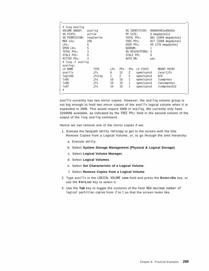
� �# lsvg availvgVOLUME GROUP: availvg VG IDENTIFIER: 000004461ed9e52eVG STATE: active PP SIZE: 4 megabyte(s)VG PERMISSION: read/write TOTAL PPs: 861 (3444 megabytes)MAX LVs: 256 FREE PPs: 817 (3268 megabytes)LVs: 5 USED PPs: 44 (176 megabytes)OPEN LVs: 5 QUORUM: 1TOTAL PVs: 3 VG DESCRIPTORS: 3STALE PVs: 0 STALE PPs 0ACTIVE PVs: 3 AUTO ON: yes# lsvg -l availvgavailvg:LV NAME TYPE LPs PPs PVs LV STATE MOUNT POINTavaillv jfs 6 12 2 open/syncd /availjfsloglv00 jfslog 1 2 2 open/syncd N/Alv05 jfs 10 10 1 open/syncd /compresslv06 jfs 10 10 1 open/syncd /uncompresslv07 jfs 10 10 1 open/syncd /compress512#� �
availlv currently has two mirror copies. However, the availvg volume group isnot big enough to hold two mirror copies of the availlv logical volume when it isexpanded to 3MB. This would require 6MB in availvg. We currently only have3268MB available, as indicated by the FREE PPs: field in the second column of theoutput of the lsvg availvg command.
Hence we can remove one of the mirror copies if we:
1. Execute the fastpath smitty rmlvcopy to get to the screen with the titleRemove Copies from a Logical Volume, or, to go through the smit hierarchy:
a. Execute smitty.
b. Select System Storage Management (Physical & Logical Storage) .
c. Select Logical Volume Manager .
d. Select Logical Volumes .
e. Select Set Characteristic of a Logical Volume .
f. Select Remove Copies from a Logical Volume .
2. Type availlv in the LOGICAL VOLUME name field and press the Enter=Do key, oruse the F4=List key to select it.
3. Use the Tab key to toggle the contents of the field NEW maximum number oflogical partition copies from 2 to 1 so that the screen looks like:
Chapter 8. Practical Examples 289
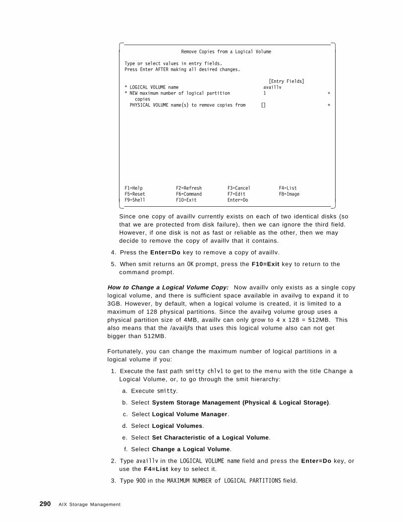
� �Remove Copies from a Logical Volume
Type or select values in entry fields.Press Enter AFTER making all desired changes.
[Entry Fields]* LOGICAL VOLUME name availlv* NEW maximum number of logical partition 1 +
copiesPHYSICAL VOLUME name(s) to remove copies from [] +
F1=Help F2=Refresh F3=Cancel F4=ListF5=Reset F6=Command F7=Edit F8=ImageF9=Shell F10=Exit Enter=Do� �
Since one copy of availlv currently exists on each of two identical disks (sothat we are protected from disk failure), then we can ignore the third field.However, if one disk is not as fast or reliable as the other, then we maydecide to remove the copy of availlv that it contains.
4. Press the Enter=Do key to remove a copy of availlv.
5. When smit returns an OK prompt, press the F10=Exit key to return to thecommand prompt.
How to Change a Logical Volume Copy: Now availlv only exists as a single copylogical volume, and there is sufficient space available in availvg to expand it to3GB. However, by default, when a logical volume is created, it is limited to amaximum of 128 physical partitions. Since the availvg volume group uses aphysical partition size of 4MB, availlv can only grow to 4 x 128 = 512MB. Thisalso means that the /availjfs that uses this logical volume also can not getbigger than 512MB.
Fortunately, you can change the maximum number of logical partitions in alogical volume if you:
1. Execute the fast path smitty chlv1 to get to the menu with the title Change aLogical Volume, or, to go through the smit hierarchy:
a. Execute smitty.
b. Select System Storage Management (Physical & Logical Storage) .
c. Select Logical Volume Manager .
d. Select Logical Volumes .
e. Select Set Characteristic of a Logical Volume .
f. Select Change a Logical Volume .
2. Type availlv in the LOGICAL VOLUME name field and press the Enter=Do key, oruse the F4=List key to select it.
3. Type 900 in the MAXIMUM NUMBER of LOGICAL PARTITIONS field.
290 AIX Storage Management
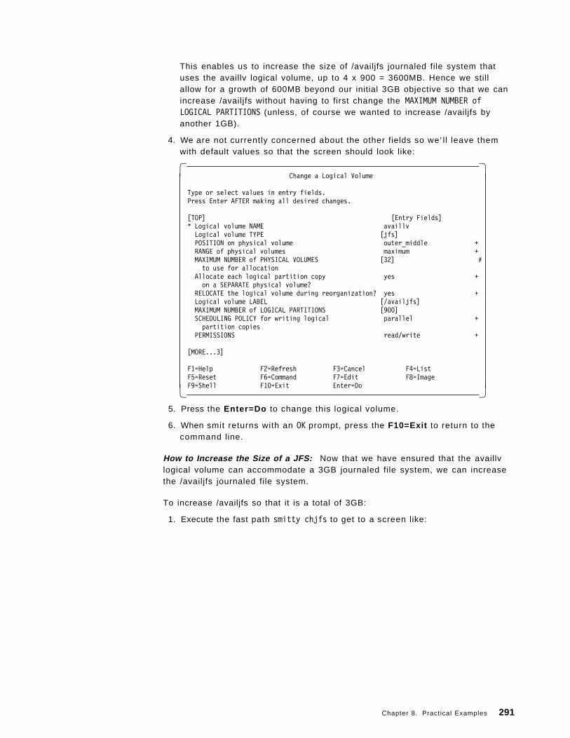
This enables us to increase the size of /availjfs journaled file system thatuses the availlv logical volume, up to 4 x 900 = 3600MB. Hence we stillallow for a growth of 600MB beyond our initial 3GB objective so that we canincrease /availjfs without having to first change the MAXIMUM NUMBER ofLOGICAL PARTITIONS (unless, of course we wanted to increase /availjfs byanother 1GB).
4. We are not currently concerned about the other fields so we ′ l l leave themwith default values so that the screen should look like:
� �Change a Logical Volume
Type or select values in entry fields.Press Enter AFTER making all desired changes.
[TOP] [Entry Fields]* Logical volume NAME availlvLogical volume TYPE [jfs]POSITION on physical volume outer_middle +RANGE of physical volumes maximum +MAXIMUM NUMBER of PHYSICAL VOLUMES [32] #to use for allocation
Allocate each logical partition copy yes +on a SEPARATE physical volume?
RELOCATE the logical volume during reorganization? yes +Logical volume LABEL [/availjfs]MAXIMUM NUMBER of LOGICAL PARTITIONS [900]SCHEDULING POLICY for writing logical parallel +partition copies
PERMISSIONS read/write +
[MORE...3]
F1=Help F2=Refresh F3=Cancel F4=ListF5=Reset F6=Command F7=Edit F8=ImageF9=Shell F10=Exit Enter=Do� �
5. Press the Enter=Do to change this logical volume.
6. When smit returns with an OK prompt, press the F10=Exit to return to thecommand line.
How to Increase the Size of a JFS: Now that we have ensured that the availlvlogical volume can accommodate a 3GB journaled file system, we can increasethe /availjfs journaled file system.
To increase /availjfs so that it is a total of 3GB:
1. Execute the fast path smitty chjfs to get to a screen like:
Chapter 8. Practical Examples 291
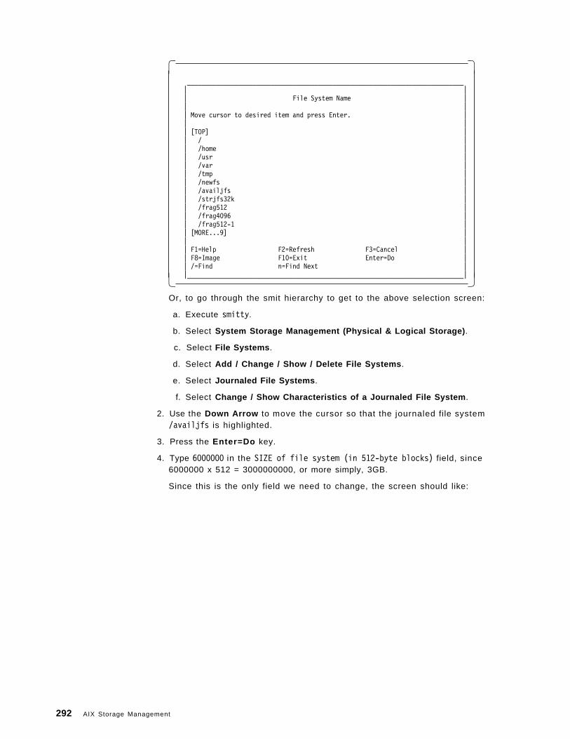
� �____________________________________________________________________________| || File System Name || || Move cursor to desired item and press Enter. || || [TOP] || / || /home || /usr || /var || /tmp || /newfs || /availjfs || /strjfs32k || /frag512 || /frag4096 || /frag512-1 || [MORE...9] || || F1=Help F2=Refresh F3=Cancel || F8=Image F10=Exit Enter=Do || /=Find n=Find Next ||____________________________________________________________________________|� �
Or, to go through the smit hierarchy to get to the above selection screen:
a. Execute smitty.
b. Select System Storage Management (Physical & Logical Storage) .
c. Select File Systems .
d. Select Add / Change / Show / Delete File Systems .
e. Select Journaled File Systems .
f. Select Change / Show Characteristics of a Journaled File System .
2. Use the Down Arrow to move the cursor so that the journaled file system/availjfs is highlighted.
3. Press the Enter=Do key.
4. Type 6000000 in the SIZE of file system (in 512-byte blocks) field, since6000000 x 512 = 3000000000, or more simply, 3GB.
Since this is the only field we need to change, the screen should like:
292 AIX Storage Management
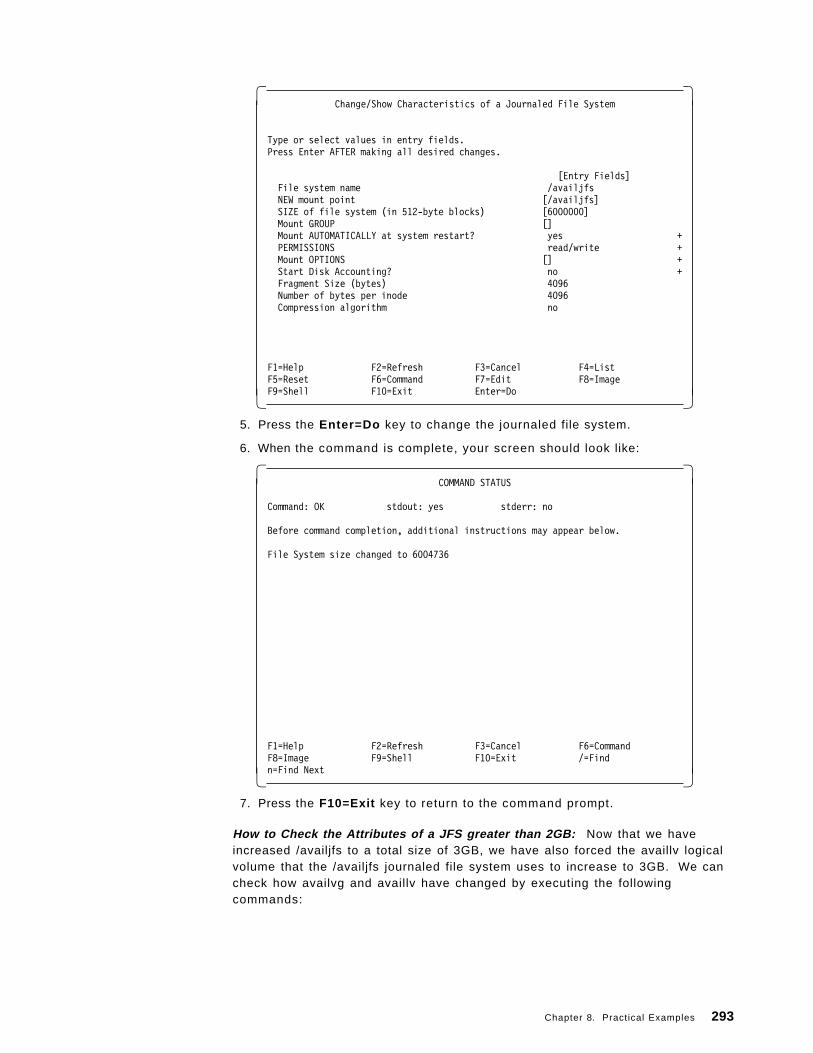
� �Change/Show Characteristics of a Journaled File System
Type or select values in entry fields.Press Enter AFTER making all desired changes.
[Entry Fields]File system name /availjfsNEW mount point [/availjfs]SIZE of file system (in 512-byte blocks) [6000000]Mount GROUP []Mount AUTOMATICALLY at system restart? yes +PERMISSIONS read/write +Mount OPTIONS [] +Start Disk Accounting? no +Fragment Size (bytes) 4096Number of bytes per inode 4096Compression algorithm no
F1=Help F2=Refresh F3=Cancel F4=ListF5=Reset F6=Command F7=Edit F8=ImageF9=Shell F10=Exit Enter=Do� �
5. Press the Enter=Do key to change the journaled file system.
6. When the command is complete, your screen should look like:
� �COMMAND STATUS
Command: OK stdout: yes stderr: no
Before command completion, additional instructions may appear below.
File System size changed to 6004736
F1=Help F2=Refresh F3=Cancel F6=CommandF8=Image F9=Shell F10=Exit /=Findn=Find Next� �
7. Press the F10=Exit key to return to the command prompt.
How to Check the Attributes of a JFS greater than 2GB: Now that we haveincreased /availjfs to a total size of 3GB, we have also forced the availlv logicalvolume that the /availjfs journaled file system uses to increase to 3GB. We cancheck how availvg and availlv have changed by executing the followingcommands:
Chapter 8. Practical Examples 293
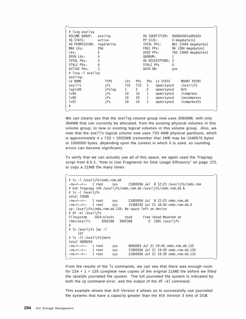
� �# lsvg availvgVOLUME GROUP: availvg VG IDENTIFIER: 000004461ed9e52eVG STATE: active PP SIZE: 4 megabyte(s)VG PERMISSION: read/write TOTAL PPs: 861 (3444 megabytes)MAX LVs: 256 FREE PPs: 96 (384 megabytes)LVs: 5 USED PPs: 765 (3060 megabytes)OPEN LVs: 5 QUORUM: 1TOTAL PVs: 3 VG DESCRIPTORS: 3STALE PVs: 0 STALE PPs 0ACTIVE PVs: 3 AUTO ON: yes# lsvg -l availvgavailvg:LV NAME TYPE LPs PPs PVs LV STATE MOUNT POINTavaillv jfs 733 733 3 open/syncd /availjfsloglv00 jfslog 1 2 2 open/syncd N/Alv05 jfs 10 10 1 open/syncd /compresslv06 jfs 10 10 1 open/syncd /uncompresslv07 jfs 10 10 1 open/syncd /compress51#� �
We can clearly see that the availvg volume group now uses 3060MB, with only384MB that can currently be allocated, from the existing physical volumes in thisvolume group, to new or existing logical volumes in this volume group. Also, wenote that the availlv logical volume now uses 733 4MB physical partitions, whichis approximately 4 x 733 = 2932MB (remember that 1MB may be 1048576 bytesor 1000000 bytes, depending upon the context in which it is used, so roundingerrors can become significant).
To verify that we can actually use all of this space, we again used the fragcopyscript from 8.5.2, “How to Use Fragments for Disk Usage Efficiency” on page 272,to copy a 21MB file many times.
� �# ls -l /availjfs/cmds.rom.dd-rw-r--r-- 1 root sys 21805056 Jul 8 12:23 /availjfs/cmds.rom# ksh fragcopy 140 /availjfs/cmds.rom.dd /availjfs/cmds.rom.dd &# ls -l /availjfstotal 72608-rw-r--r-- 1 root sys 21805056 Jul 8 12:23 cmds.rom.dd-rw-r--r-- 1 root sys 15368192 Jul 21 18:50 cmds.rom.dd.0cp: /availjfs/cmds.rom.dd.135: No space left on device# df -kI /availjfsFilesystem 1024-blocks Used Free %Used Mounted on/dev/availlv 3002368 3002368 0 100% /availjfs## ls /availjfs |wc -l
137# ls -lt /availjfs|moretotal 5808264-rw-r--r-- 1 root sys 8065024 Jul 21 19:40 cmds.rom.dd.135-rw-r--r-- 1 root sys 21805056 Jul 21 19:40 cmds.rom.dd.134-rw-r--r-- 1 root sys 21805056 Jul 21 19:39 cmds.rom.dd.133� �
From the results of the ls commands, we can see that there was enough roomfor 134 + 1 = 135 complete new copies of the original 21MB file before we filledthe /availjfs journaled file system. The full journaled file system is indicated byboth the cp command error, and the output of the df -kI command.
This example shows that AIX Version 4 allows us to successfully use journaledfile systems that have a capacity greater than the AIX Version 3 limit of 2GB.
294 AIX Storage Management
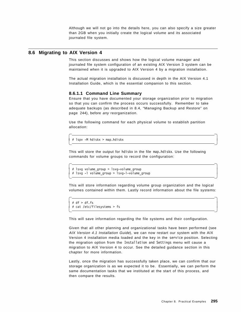
Although we will not go into the details here, you can also specify a size greaterthan 2GB when you initially create the logical volume and its associatedjournaled file system.
8.6 Migrating to AIX Version 4This section discusses and shows how the logical volume manager andjournaled file system configuration of an existing AIX Version 3 system can bemaintained when it is upgraded to AIX Version 4 by a migration installation.
The actual migration installation is discussed in depth in the AIX Version 4.1Installation Guide, which is the essential companion to this section.
8.6.1.1 Command Line SummaryEnsure that you have documented your storage organization prior to migrationso that you can confirm the process occurs successfully. Remember to takeadequate backups (as described in 8.4, “Managing Backup and Restore” onpage 244), before any reorganization.
Use the following command for each physical volume to establish partitionallocation:
� �# lspv -M hdiskx > map.hdiskx� �
This will store the output for hdiskx in the file map.hdiskx. Use the followingcommands for volume groups to record the configuration:
� �# lsvg volume_group > lsvg-volume_group# lsvg -l volume_group > lsvg-l-volume_group� �
This will store information regarding volume group organization and the logicalvolumes contained within them. Lastly record information about the file systems:
� �# df > df.fs# cat /etc/filesystems > fs� �
This will save information regarding the file systems and their configuration.
Given that all other planning and organizational tasks have been performed (seeAIX Version 4.1 Installation Guide), we can now restart our system with the AIXVersion 4 installation media loaded and the key in the service position. Selectingthe migration option from the Installation and Settings menu will cause amigration to AIX Version 4 to occur. See the detailed guidance section in thischapter for more information.
Lastly, once the migration has successfully taken place, we can confirm that ourstorage organization is as we expected it to be. Essentially, we can perform thesame documentation tasks that we instituted at the start of this process, andthen compare the results.
Chapter 8. Practical Examples 295
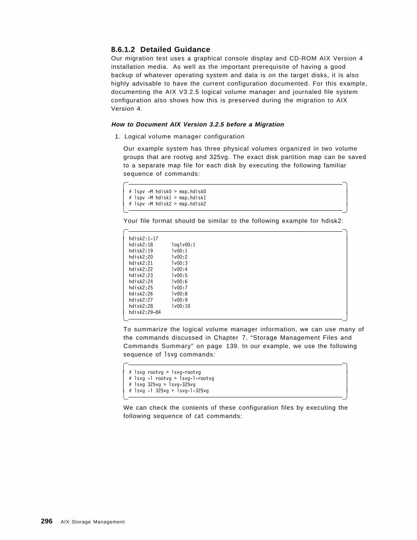
8.6.1.2 Detailed GuidanceOur migration test uses a graphical console display and CD-ROM AIX Version 4installation media. As well as the important prerequisite of having a goodbackup of whatever operating system and data is on the target disks, it is alsohighly advisable to have the current configuration documented. For this example,documenting the AIX V3.2.5 logical volume manager and journaled file systemconfiguration also shows how this is preserved during the migration to AIXVersion 4.
How to Document AIX Version 3.2.5 before a Migration
1. Logical volume manager configuration
Our example system has three physical volumes organized in two volumegroups that are rootvg and 325vg. The exact disk partition map can be savedto a separate map file for each disk by executing the following familiarsequence of commands:
� �# lspv -M hdisk0 > map.hdisk0# lspv -M hdisk1 > map.hdisk1# lspv -M hdisk2 > map.hdisk2� �
Your file format should be similar to the following example for hdisk2:
� �hdisk2:1-17hdisk2:18 loglv00:1hdisk2:19 lv00:1hdisk2:20 lv00:2hdisk2:21 lv00:3hdisk2:22 lv00:4hdisk2:23 lv00:5hdisk2:24 lv00:6hdisk2:25 lv00:7hdisk2:26 lv00:8hdisk2:27 lv00:9hdisk2:28 lv00:10hdisk2:29-84� �
To summarize the logical volume manager information, we can use many ofthe commands discussed in Chapter 7, “Storage Management Files andCommands Summary” on page 139. In our example, we use the followingsequence of lsvg commands:
� �# lsvg rootvg > lsvg-rootvg# lsvg -l rootvg > lsvg-l-rootvg# lsvg 325vg > lsvg-325vg# lsvg -l 325vg > lsvg-l-325vg� �
We can check the contents of these configuration files by executing thefollowing sequence of cat commands:
296 AIX Storage Management
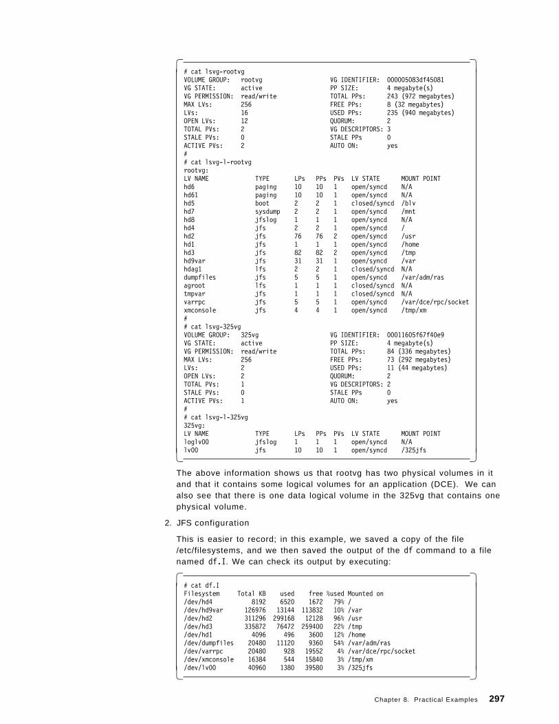
� �# cat lsvg-rootvgVOLUME GROUP: rootvg VG IDENTIFIER: 000005083df45081VG STATE: active PP SIZE: 4 megabyte(s)VG PERMISSION: read/write TOTAL PPs: 243 (972 megabytes)MAX LVs: 256 FREE PPs: 8 (32 megabytes)LVs: 16 USED PPs: 235 (940 megabytes)OPEN LVs: 12 QUORUM: 2TOTAL PVs: 2 VG DESCRIPTORS: 3STALE PVs: 0 STALE PPs 0ACTIVE PVs: 2 AUTO ON: yes## cat lsvg-l-rootvgrootvg:LV NAME TYPE LPs PPs PVs LV STATE MOUNT POINThd6 paging 10 10 1 open/syncd N/Ahd61 paging 10 10 1 open/syncd N/Ahd5 boot 2 2 1 closed/syncd /blvhd7 sysdump 2 2 1 open/syncd /mnthd8 jfslog 1 1 1 open/syncd N/Ahd4 jfs 2 2 1 open/syncd /hd2 jfs 76 76 2 open/syncd /usrhd1 jfs 1 1 1 open/syncd /homehd3 jfs 82 82 2 open/syncd /tmphd9var jfs 31 31 1 open/syncd /varhdag1 lfs 2 2 1 closed/syncd N/Adumpfiles jfs 5 5 1 open/syncd /var/adm/rasagroot lfs 1 1 1 closed/syncd N/Atmpvar jfs 1 1 1 closed/syncd N/Avarrpc jfs 5 5 1 open/syncd /var/dce/rpc/socketxmconsole jfs 4 4 1 open/syncd /tmp/xm## cat lsvg-325vgVOLUME GROUP: 325vg VG IDENTIFIER: 00011605f67f40e9VG STATE: active PP SIZE: 4 megabyte(s)VG PERMISSION: read/write TOTAL PPs: 84 (336 megabytes)MAX LVs: 256 FREE PPs: 73 (292 megabytes)LVs: 2 USED PPs: 11 (44 megabytes)OPEN LVs: 2 QUORUM: 2TOTAL PVs: 1 VG DESCRIPTORS: 2STALE PVs: 0 STALE PPs 0ACTIVE PVs: 1 AUTO ON: yes## cat lsvg-l-325vg325vg:LV NAME TYPE LPs PPs PVs LV STATE MOUNT POINTloglv00 jfslog 1 1 1 open/syncd N/Alv00 jfs 10 10 1 open/syncd /325jfs� �
The above information shows us that rootvg has two physical volumes in itand that it contains some logical volumes for an application (DCE). We canalso see that there is one data logical volume in the 325vg that contains onephysical volume.
2. JFS configuration
This is easier to record; in this example, we saved a copy of the file/etc/filesystems, and we then saved the output of the df command to a filenamed df.I. We can check its output by executing:
� �# cat df.IFilesystem Total KB used free %used Mounted on/dev/hd4 8192 6520 1672 79% //dev/hd9var 126976 13144 113832 10% /var/dev/hd2 311296 299168 12128 96% /usr/dev/hd3 335872 76472 259400 22% /tmp/dev/hd1 4096 496 3600 12% /home/dev/dumpfiles 20480 11120 9360 54% /var/adm/ras/dev/varrpc 20480 928 19552 4% /var/dce/rpc/socket/dev/xmconsole 16384 544 15840 3% /tmp/xm/dev/lv00 40960 1380 39580 3% /325jfs� �
Chapter 8. Practical Examples 297
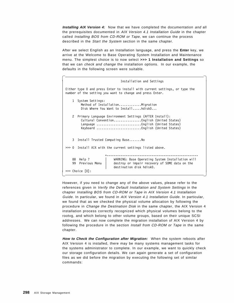
Installing AIX Version 4: Now that we have completed the documentation and allthe prerequisites documented in AIX Version 4.1 Installation Guide in the chaptercalled Installing BOS from CD-ROM or Tape, we can continue the processdescribed in the Start the System section in the same chapter.
After we select English as an Installation language, and press the Enter key, wearrive at the Welcome to Base Operating System Installation and Maintenancemenu. The simplest choice is to now select >>> 1 Installation and Settings sothat we can check and change the installation options. In our example, thedefaults in the following screen were suitable.
� �Installation and Settings
Either type 0 and press Enter to install with current settings, or type thenumber of the setting you want to change and press Enter.
1 System Settings:Method of Installation.............MigrationDisk Where You Want to Install.....hdisk0...
2 Primary Language Environment Settings (AFTER Install):Cultural Convention................English (United States)Language ..........................English (United States)Keyboard ..........................English (United States)
3 Install Trusted Computing Base.......No
>>> 0 Install AIX with the current settings listed above.
+-----------------------------------------------------88 Help ? | WARNING: Base Operating System Installation will99 Previous Menu | destroy or impair recovery of SOME data on the
| destination disk hdisk0.>>> Choice [0]:� �
However, if you need to change any of the above values, please refer to thereferences given in Verify the Default Installation and System Settings in thechapter Installing BOS from CD-ROM or Tape in AIX Version 4.1 InstallationGuide. In particular, we found in AIX Version 4.1 Installation Guide. In particular,we found that as we checked the physical volume allocation by following theprocedure in Change the Destination Disk in the same chapter, the AIX Version 4installation process correctly recognized which physical volumes belong to therootvg, and which belong to other volume groups, based on their unique SCSIaddresses. We can now complete the migration installation of AIX Version 4 byfollowing the procedure in the section Install from CD-ROM or Tape in the samechapter.
How to Check the Configuration after Migration: When the system reboots afterAIX Version 4 is installed, there may be many systems management tasks forthe systems administrator to complete. In our example, we want to quickly checkour storage configuration details. We can again generate a set of configurationfiles as we did before the migration by executing the following set of similarcommands:
298 AIX Storage Management
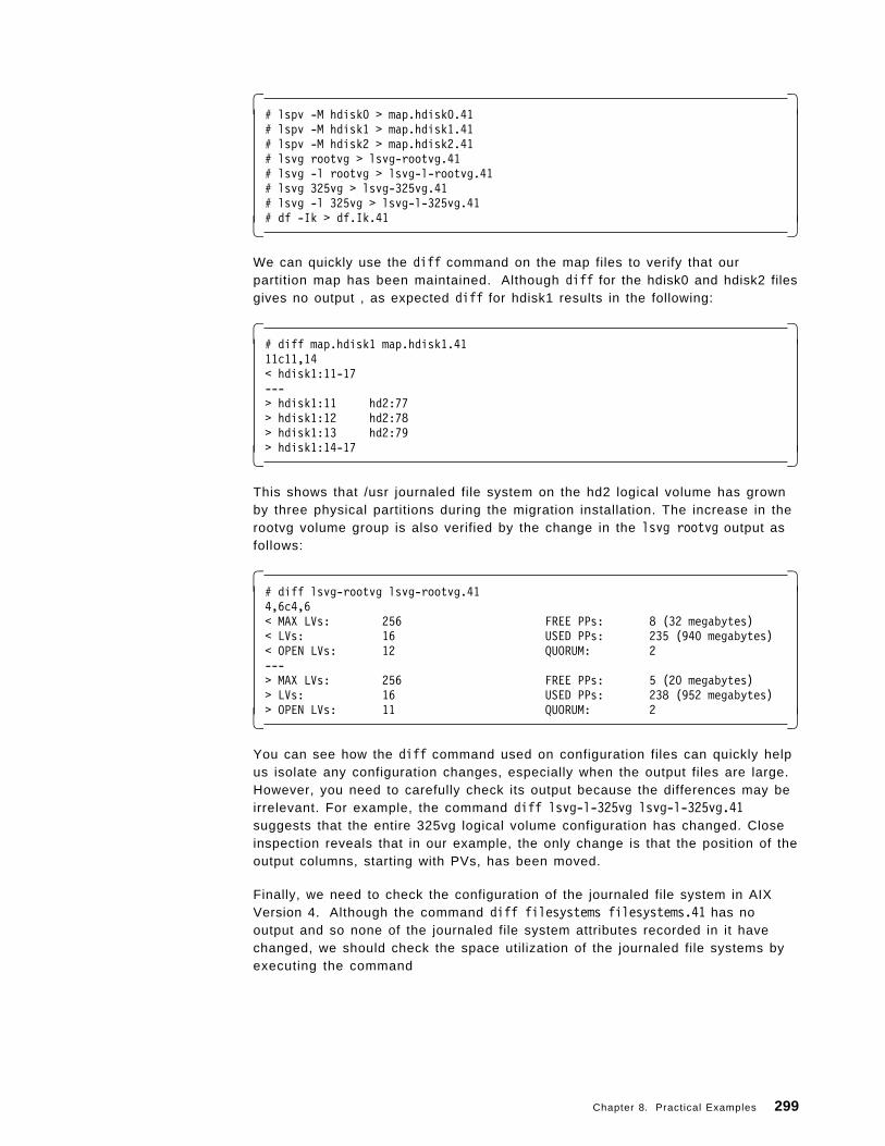
� �# lspv -M hdisk0 > map.hdisk0.41# lspv -M hdisk1 > map.hdisk1.41# lspv -M hdisk2 > map.hdisk2.41# lsvg rootvg > lsvg-rootvg.41# lsvg -l rootvg > lsvg-l-rootvg.41# lsvg 325vg > lsvg-325vg.41# lsvg -l 325vg > lsvg-l-325vg.41# df -Ik > df.Ik.41� �
We can quickly use the diff command on the map files to verify that ourpartition map has been maintained. Although diff for the hdisk0 and hdisk2 filesgives no output , as expected diff for hdisk1 results in the following:
� �# diff map.hdisk1 map.hdisk1.4111c11,14< hdisk1:11-17---> hdisk1:11 hd2:77> hdisk1:12 hd2:78> hdisk1:13 hd2:79> hdisk1:14-17� �
This shows that /usr journaled file system on the hd2 logical volume has grownby three physical partitions during the migration installation. The increase in therootvg volume group is also verified by the change in the lsvg rootvg output asfollows:
� �# diff lsvg-rootvg lsvg-rootvg.414,6c4,6< MAX LVs: 256 FREE PPs: 8 (32 megabytes)< LVs: 16 USED PPs: 235 (940 megabytes)< OPEN LVs: 12 QUORUM: 2---> MAX LVs: 256 FREE PPs: 5 (20 megabytes)> LVs: 16 USED PPs: 238 (952 megabytes)> OPEN LVs: 11 QUORUM: 2� �
You can see how the diff command used on configuration files can quickly helpus isolate any configuration changes, especially when the output files are large.However, you need to carefully check its output because the differences may beirrelevant. For example, the command diff lsvg-l-325vg lsvg-l-325vg.41suggests that the entire 325vg logical volume configuration has changed. Closeinspection reveals that in our example, the only change is that the position of theoutput columns, starting with PVs, has been moved.
Finally, we need to check the configuration of the journaled file system in AIXVersion 4. Although the command diff filesystems filesystems.41 has nooutput and so none of the journaled file system attributes recorded in it havechanged, we should check the space utilization of the journaled file systems byexecuting the command
Chapter 8. Practical Examples 299
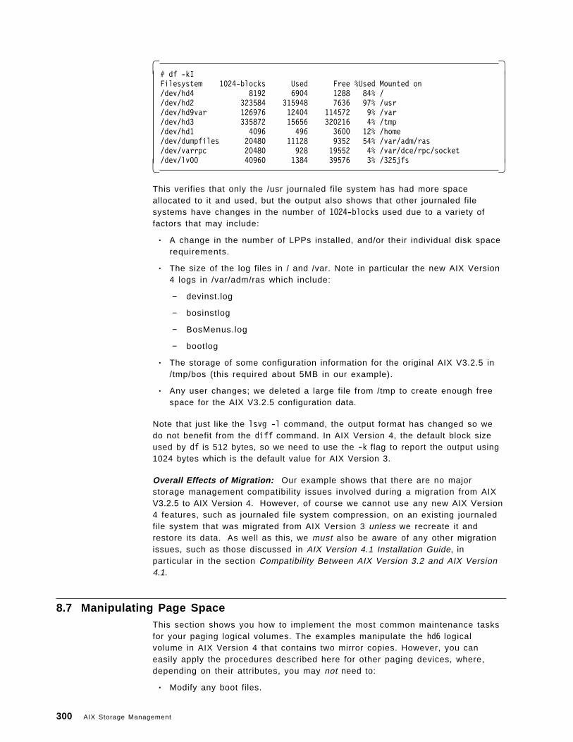
� �# df -kIFilesystem 1024-blocks Used Free %Used Mounted on/dev/hd4 8192 6904 1288 84% //dev/hd2 323584 315948 7636 97% /usr/dev/hd9var 126976 12404 114572 9% /var/dev/hd3 335872 15656 320216 4% /tmp/dev/hd1 4096 496 3600 12% /home/dev/dumpfiles 20480 11128 9352 54% /var/adm/ras/dev/varrpc 20480 928 19552 4% /var/dce/rpc/socket/dev/lv00 40960 1384 39576 3% /325jfs� �
This verifies that only the /usr journaled file system has had more spaceallocated to it and used, but the output also shows that other journaled filesystems have changes in the number of 1024-blocks used due to a variety offactors that may include:
• A change in the number of LPPs installed, and/or their individual disk spacerequirements.
• The size of the log files in / and /var. Note in particular the new AIX Version4 logs in /var/adm/ras which include:
− devinst.log
− bosinstlog
− BosMenus.log
− bootlog
• The storage of some configuration information for the original AIX V3.2.5 in/tmp/bos (this required about 5MB in our example).
• Any user changes; we deleted a large file from /tmp to create enough freespace for the AIX V3.2.5 configuration data.
Note that just like the lsvg -l command, the output format has changed so wedo not benefit from the diff command. In AIX Version 4, the default block sizeused by df is 512 bytes, so we need to use the -k flag to report the output using1024 bytes which is the default value for AIX Version 3.
Overall Effects of Migration: Our example shows that there are no majorstorage management compatibility issues involved during a migration from AIXV3.2.5 to AIX Version 4. However, of course we cannot use any new AIX Version4 features, such as journaled file system compression, on an existing journaledfile system that was migrated from AIX Version 3 unless we recreate it andrestore its data. As well as this, we must also be aware of any other migrationissues, such as those discussed in AIX Version 4.1 Installation Guide, inparticular in the section Compatibility Between AIX Version 3.2 and AIX Version4.1.
8.7 Manipulating Page SpaceThis section shows you how to implement the most common maintenance tasksfor your paging logical volumes. The examples manipulate the hd6 logicalvolume in AIX Version 4 that contains two mirror copies. However, you caneasily apply the procedures described here for other paging devices, where,depending on their attributes, you may not need to:
• Modify any boot files.
300 AIX Storage Management
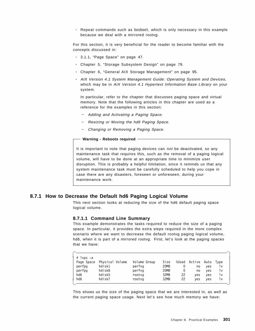
• Repeat commands such as bosboot, which is only necessary in this examplebecause we deal with a mirrored rootvg.
For this section, it is very beneficial for the reader to become familiar with theconcepts discussed in:
• 3.1.1, “Page Space” on page 47.
• Chapter 5, “Storage Subsystem Design” on page 79.
• Chapter 6, “General AIX Storage Management” on page 95.
• AIX Version 4.1 System Management Guide: Operating System and Devices,which may be in AIX Version 4.1 Hypertext Information Base Library on yoursystem.
In particular, refer to the chapter that discusses paging space and virtualmemory. Note that the following articles in this chapter are used as areference for the examples in this section:
− Adding and Activating a Paging Space.
− Resizing or Moving the hd6 Paging Space.
− Changing or Removing a Paging Space.
Warning - Reboots required
It is important to note that paging devices can not be deactivated, so anymaintenance task that requires this, such as the removal of a paging logicalvolume, will have to be done at an appropriate time to minimize userdisruption. This is probably a helpful limitation, since it reminds us that anysystem maintenance task must be carefully scheduled to help you cope incase there are any disasters, foreseen or unforeseen, during yourmaintenance work.
8.7.1 How to Decrease the Default hd6 Paging Logical VolumeThis next section looks at reducing the size of the hd6 default paging spacelogical volume.
8.7.1.1 Command Line SummaryThis example demonstrates the tasks required to reduce the size of a pagingspace. In particular, it provides the extra steps required in the more complexscenario where we want to decrease the default rootvg paging logical volume,hd6, when it is part of a mirrored rootvg. First, let′s look at the paging spacesthat we have:
� �# lsps -aPage Space Physical Volume Volume Group Size %Used Active Auto Typeperfpg hdisk1 perfvg 20MB 0 no yes lvperfpg hdisk8 perfvg 20MB 0 no yes lvhd6 hdisk5 rootvg 32MB 22 yes yes lvhd6 hdisk7 rootvg 32MB 22 yes yes lv� �
This shows us the size of the paging space that we are interested in, as well asthe current paging space usage. Next let′s see how much memory we have:
Chapter 8. Practical Examples 301
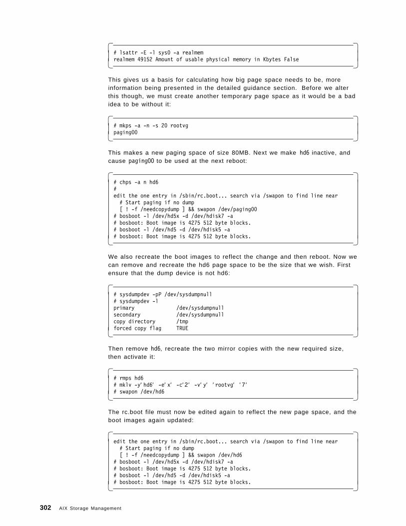
� �# lsattr -E -l sys0 -a realmemrealmem 49152 Amount of usable physical memory in Kbytes False� �
This gives us a basis for calculating how big page space needs to be, moreinformation being presented in the detailed guidance section. Before we alterthis though, we must create another temporary page space as it would be a badidea to be without it:
� �# mkps -a -n -s 20 rootvgpaging00� �
This makes a new paging space of size 80MB. Next we make hd6 inactive, andcause paging00 to be used at the next reboot:
� �# chps -a n hd6#edit the one entry in /sbin/rc.boot... search via /swapon to find line near# Start paging if no dump[ ! -f /needcopydump ] && swapon /dev/paging00
# bosboot -l /dev/hd5x -d /dev/hdisk7 -a# bosboot: Boot image is 4275 512 byte blocks.# bosboot -l /dev/hd5 -d /dev/hdisk5 -a# bosboot: Boot image is 4275 512 byte blocks.� �
We also recreate the boot images to reflect the change and then reboot. Now wecan remove and recreate the hd6 page space to be the size that we wish. Firstensure that the dump device is not hd6:
� �# sysdumpdev -pP /dev/sysdumpnull# sysdumpdev -lprimary /dev/sysdumpnullsecondary /dev/sysdumpnullcopy directory /tmpforced copy flag TRUE� �
Then remove hd6, recreate the two mirror copies with the new required size,then activate it:
� �# rmps hd6# mklv -y′ hd6′ -e′ x′ -c′ 2 ′ -v′ y′ ′ rootvg′ ′ 7 ′# swapon /dev/hd6� �
The rc.boot file must now be edited again to reflect the new page space, and theboot images again updated:
� �edit the one entry in /sbin/rc.boot... search via /swapon to find line near# Start paging if no dump[ ! -f /needcopydump ] && swapon /dev/hd6
# bosboot -l /dev/hd5x -d /dev/hdisk7 -a# bosboot: Boot image is 4275 512 byte blocks.# bosboot -l /dev/hd5 -d /dev/hdisk5 -a# bosboot: Boot image is 4275 512 byte blocks.� �
302 AIX Storage Management
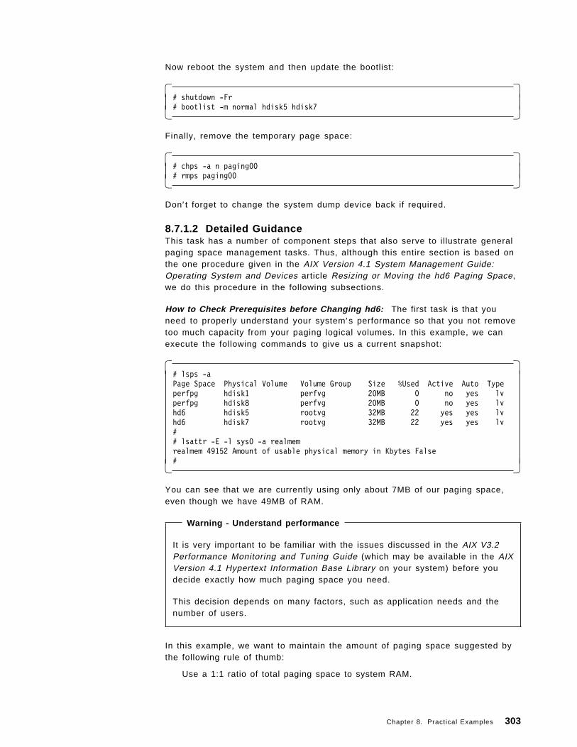
Now reboot the system and then update the bootlist:
� �# shutdown -Fr# bootlist -m normal hdisk5 hdisk7� �
Finally, remove the temporary page space:
� �# chps -a n paging00# rmps paging00� �
Don′ t forget to change the system dump device back if required.
8.7.1.2 Detailed GuidanceThis task has a number of component steps that also serve to illustrate generalpaging space management tasks. Thus, although this entire section is based onthe one procedure given in the AIX Version 4.1 System Management Guide:Operating System and Devices article Resizing or Moving the hd6 Paging Space,we do this procedure in the following subsections.
How to Check Prerequisites before Changing hd6: The first task is that youneed to properly understand your system′s performance so that you not removetoo much capacity from your paging logical volumes. In this example, we canexecute the following commands to give us a current snapshot:
� �# lsps -aPage Space Physical Volume Volume Group Size %Used Active Auto Typeperfpg hdisk1 perfvg 20MB 0 no yes lvperfpg hdisk8 perfvg 20MB 0 no yes lvhd6 hdisk5 rootvg 32MB 22 yes yes lvhd6 hdisk7 rootvg 32MB 22 yes yes lv## lsattr -E -l sys0 -a realmemrealmem 49152 Amount of usable physical memory in Kbytes False#� �
You can see that we are currently using only about 7MB of our paging space,even though we have 49MB of RAM.
Warning - Understand performance
It is very important to be familiar with the issues discussed in the AIX V3.2Performance Monitoring and Tuning Guide (which may be available in the AIXVersion 4.1 Hypertext Information Base Library on your system) before youdecide exactly how much paging space you need.
This decision depends on many factors, such as application needs and thenumber of users.
In this example, we want to maintain the amount of paging space suggested bythe following rule of thumb:
Use a 1:1 ratio of total paging space to system RAM.
Chapter 8. Practical Examples 303
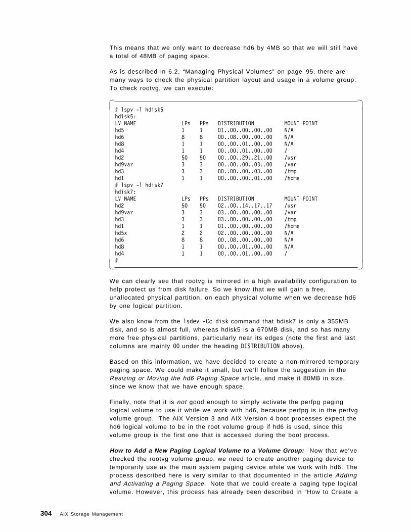
This means that we only want to decrease hd6 by 4MB so that we will still havea total of 48MB of paging space.
As is described in 6.2, “Managing Physical Volumes” on page 95, there aremany ways to check the physical partition layout and usage in a volume group.To check rootvg, we can execute:
� �# lspv -l hdisk5hdisk5:LV NAME LPs PPs DISTRIBUTION MOUNT POINThd5 1 1 01..00..00..00..00 N/Ahd6 8 8 00..08..00..00..00 N/Ahd8 1 1 00..00..01..00..00 N/Ahd4 1 1 00..00..01..00..00 /hd2 50 50 00..00..29..21..00 /usrhd9var 3 3 00..00..00..03..00 /varhd3 3 3 00..00..00..03..00 /tmphd1 1 1 00..00..00..01..00 /home# lspv -l hdisk7hdisk7:LV NAME LPs PPs DISTRIBUTION MOUNT POINThd2 50 50 02..00..14..17..17 /usrhd9var 3 3 03..00..00..00..00 /varhd3 3 3 03..00..00..00..00 /tmphd1 1 1 01..00..00..00..00 /homehd5x 2 2 02..00..00..00..00 N/Ahd6 8 8 00..08..00..00..00 N/Ahd8 1 1 00..00..01..00..00 N/Ahd4 1 1 00..00..01..00..00 /#� �
We can clearly see that rootvg is mirrored in a high availability configuration tohelp protect us from disk failure. So we know that we will gain a free,unallocated physical partition, on each physical volume when we decrease hd6by one logical partition.
We also know from the lsdev -Cc disk command that hdisk7 is only a 355MBdisk, and so is almost full, whereas hdisk5 is a 670MB disk, and so has manymore free physical partitions, particularly near its edges (note the first and lastcolumns are mainly 00 under the heading DISTRIBUTION above).
Based on this information, we have decided to create a non-mirrored temporarypaging space. We could make it small, but we′ ll follow the suggestion in theResizing or Moving the hd6 Paging Space article, and make it 80MB in size,since we know that we have enough space.
Finally, note that it is not good enough to simply activate the perfpg paginglogical volume to use it while we work with hd6, because perfpg is in the perfvgvolume group. The AIX Version 3 and AIX Version 4 boot processes expect thehd6 logical volume to be in the root volume group if hd6 is used, since thisvolume group is the first one that is accessed during the boot process.
How to Add a New Paging Logical Volume to a Volume Group: Now that we′vechecked the rootvg volume group, we need to create another paging device totemporarily use as the main system paging device while we work with hd6. Theprocess described here is very similar to that documented in the article Addingand Activating a Paging Space. Note that we could create a paging type logicalvolume. However, this process has already been described in “How to Create a
304 AIX Storage Management
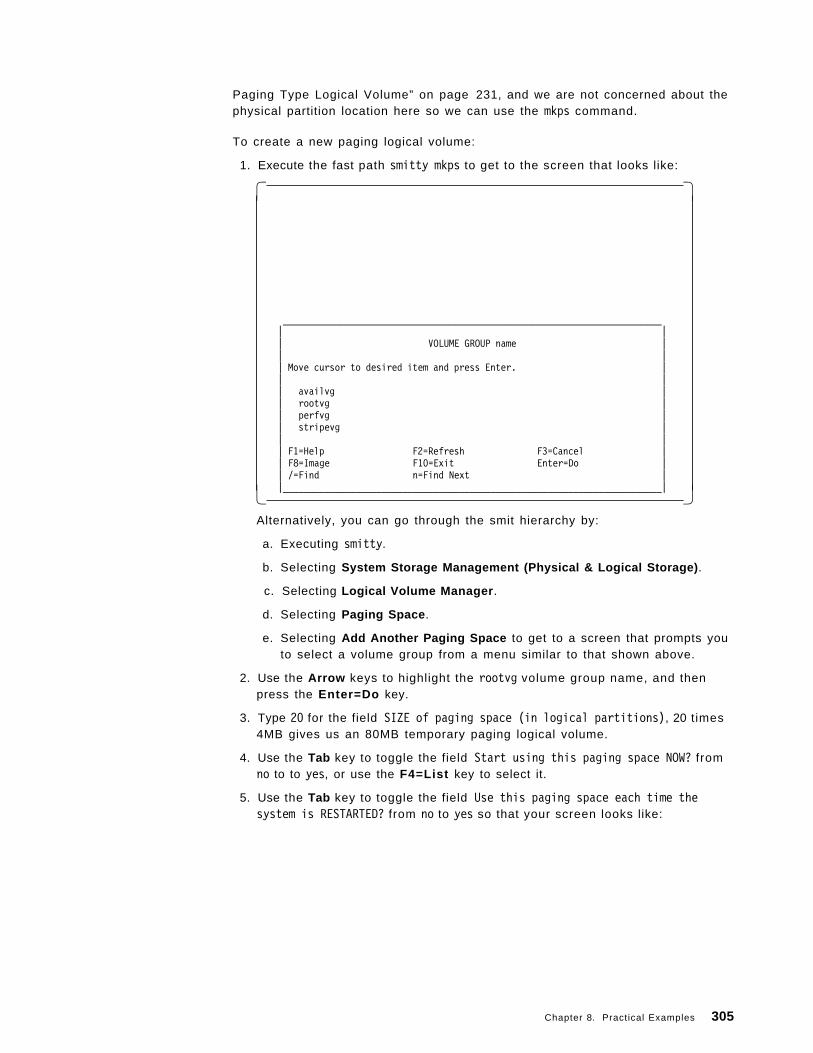
Paging Type Logical Volume” on page 231, and we are not concerned about thephysical partition location here so we can use the mkps command.
To create a new paging logical volume:
1. Execute the fast path smitty mkps to get to the screen that looks like:
� �
_________________________________________________________________________| || VOLUME GROUP name || || Move cursor to desired item and press Enter. || || availvg || rootvg || perfvg || stripevg || || F1=Help F2=Refresh F3=Cancel || F8=Image F10=Exit Enter=Do || /=Find n=Find Next ||_________________________________________________________________________|� �
Alternatively, you can go through the smit hierarchy by:
a. Executing smitty.
b. Selecting System Storage Management (Physical & Logical Storage) .
c. Selecting Logical Volume Manager .
d. Selecting Paging Space .
e. Selecting Add Another Paging Space to get to a screen that prompts youto select a volume group from a menu similar to that shown above.
2. Use the Arrow keys to highlight the rootvg volume group name, and thenpress the Enter=Do key.
3. Type 20 for the field SIZE of paging space (in logical partitions), 20 times4MB gives us an 80MB temporary paging logical volume.
4. Use the Tab key to toggle the field Start using this paging space NOW? fromno to to yes, or use the F4=List key to select it.
5. Use the Tab key to toggle the field Use this paging space each time thesystem is RESTARTED? from no to yes so that your screen looks like:
Chapter 8. Practical Examples 305
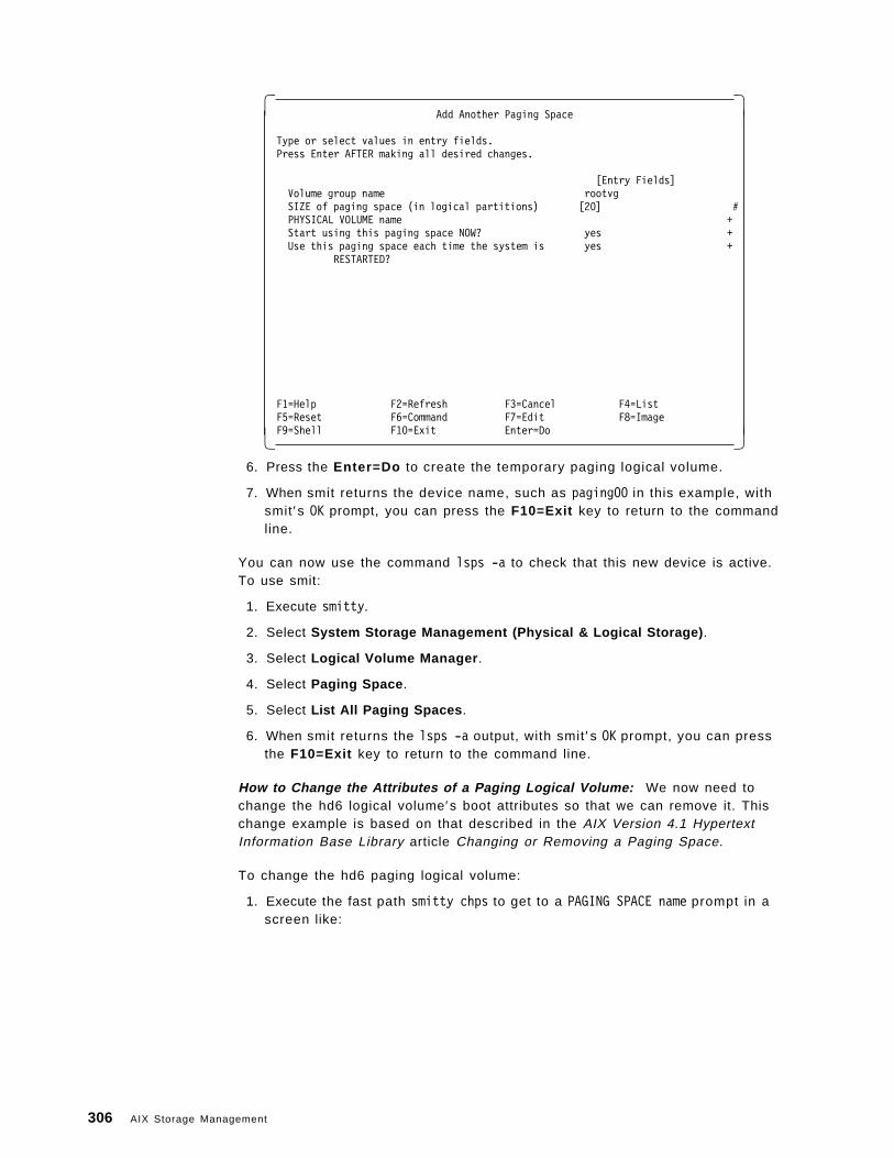
� �Add Another Paging Space
Type or select values in entry fields.Press Enter AFTER making all desired changes.
[Entry Fields]Volume group name rootvgSIZE of paging space (in logical partitions) [20] #PHYSICAL VOLUME name +Start using this paging space NOW? yes +Use this paging space each time the system is yes +
RESTARTED?
F1=Help F2=Refresh F3=Cancel F4=ListF5=Reset F6=Command F7=Edit F8=ImageF9=Shell F10=Exit Enter=Do� �
6. Press the Enter=Do to create the temporary paging logical volume.
7. When smit returns the device name, such as paging00 in this example, withsmit ′s OK prompt, you can press the F10=Exit key to return to the commandline.
You can now use the command lsps -a to check that this new device is active.To use smit:
1. Execute smitty.
2. Select System Storage Management (Physical & Logical Storage) .
3. Select Logical Volume Manager .
4. Select Paging Space .
5. Select List All Paging Spaces .
6. When smit returns the lsps -a output, with smit ′s OK prompt, you can pressthe F10=Exit key to return to the command line.
How to Change the Attributes of a Paging Logical Volume: We now need tochange the hd6 logical volume′s boot attributes so that we can remove it. Thischange example is based on that described in the AIX Version 4.1 HypertextInformation Base Library article Changing or Removing a Paging Space.
To change the hd6 paging logical volume:
1. Execute the fast path smitty chps to get to a PAGING SPACE name prompt in ascreen like:
306 AIX Storage Management
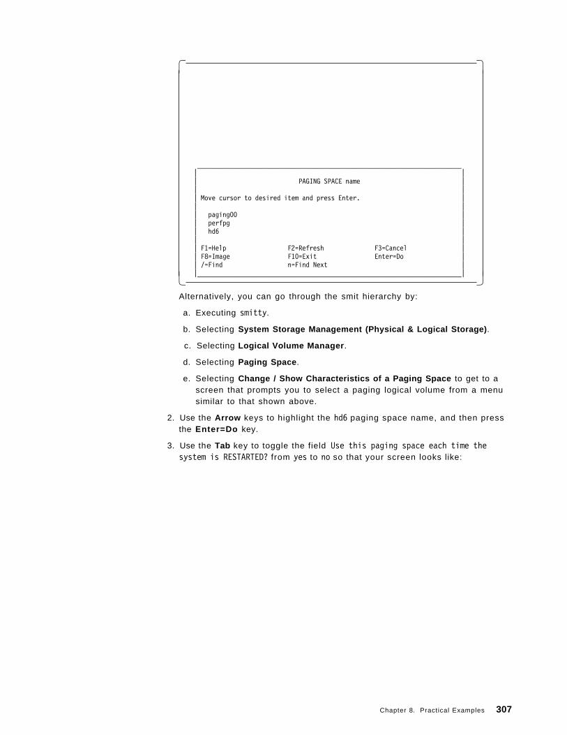
� �
_________________________________________________________________________| || PAGING SPACE name || || Move cursor to desired item and press Enter. || || paging00 || perfpg || hd6 || || F1=Help F2=Refresh F3=Cancel || F8=Image F10=Exit Enter=Do || /=Find n=Find Next ||_________________________________________________________________________|� �
Alternatively, you can go through the smit hierarchy by:
a. Executing smitty.
b. Selecting System Storage Management (Physical & Logical Storage) .
c. Selecting Logical Volume Manager .
d. Selecting Paging Space .
e. Selecting Change / Show Characteristics of a Paging Space to get to ascreen that prompts you to select a paging logical volume from a menusimilar to that shown above.
2. Use the Arrow keys to highlight the hd6 paging space name, and then pressthe Enter=Do key.
3. Use the Tab key to toggle the field Use this paging space each time thesystem is RESTARTED? from yes to no so that your screen looks like:
Chapter 8. Practical Examples 307
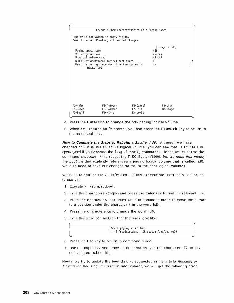
� �Change / Show Characteristics of a Paging Space
Type or select values in entry fields.Press Enter AFTER making all desired changes.
[Entry Fields]Paging space name hd6Volume group name rootvgPhysical volume name hdisk5NUMBER of additional logical partitions [] #Use this paging space each time the system is no +
RESTARTED?
F1=Help F2=Refresh F3=Cancel F4=ListF5=Reset F6=Command F7=Edit F8=ImageF9=Shell F10=Exit Enter=Do� �
4. Press the Enter=Do to change the hd6 paging logical volume.
5. When smit returns an OK prompt, you can press the F10=Exit key to return tothe command line.
How to Complete the Steps to Rebuild a Smaller hd6: Although we havechanged hd6, it is still an active logical volume (you can see that its LV STATE isopen/syncd if you execute the lsvg -l rootvg command). Hence we must use thecommand shutdown -Fr to reboot the RISC System/6000, but we must first modifythe boot file that explicitly references a paging logical volume that is called hd6.We also need to save our changes so far, to the boot logical volumes.
We need to edit the file /sbin/rc.boot. In this example we used the vi editor, soto use vi:
1. Execute vi /sbin/rc.boot.
2. Type the characters /swapon and press the Enter key to find the relevant line.
3. Press the character w four t imes while in command mode to move the cursorto a position under the character h in the word hd6.
4. Press the characters cw to change the word hd6.
5. Type the word paging00 so that the lines look like:
� �# Start paging if no dump[ ! -f /needcopydump ] && swapon /dev/paging00� �
6. Press the Esc key to return to command mode.
7. Use the capital zz sequence, in other words type the characters ZZ, to saveour updated rc.boot file.
Now if we try to update the boot disk as suggested in the article Resizing orMoving the hd6 Paging Space in InfoExplorer, we will get the following error:
308 AIX Storage Management
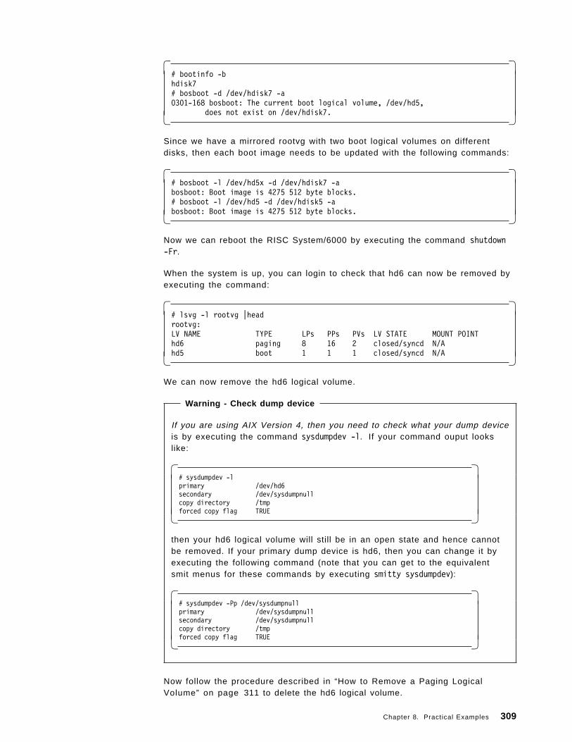
� �# bootinfo -bhdisk7# bosboot -d /dev/hdisk7 -a0301-168 bosboot: The current boot logical volume, /dev/hd5,
does not exist on /dev/hdisk7.� �
Since we have a mirrored rootvg with two boot logical volumes on differentdisks, then each boot image needs to be updated with the following commands:
� �# bosboot -l /dev/hd5x -d /dev/hdisk7 -abosboot: Boot image is 4275 512 byte blocks.# bosboot -l /dev/hd5 -d /dev/hdisk5 -abosboot: Boot image is 4275 512 byte blocks.� �
Now we can reboot the RISC System/6000 by executing the command shutdown-Fr.
When the system is up, you can login to check that hd6 can now be removed byexecuting the command:
� �# lsvg -l rootvg |headrootvg:LV NAME TYPE LPs PPs PVs LV STATE MOUNT POINThd6 paging 8 16 2 closed/syncd N/Ahd5 boot 1 1 1 closed/syncd N/A� �
We can now remove the hd6 logical volume.
Warning - Check dump device
If you are using AIX Version 4, then you need to check what your dump deviceis by executing the command sysdumpdev -l. If your command ouput lookslike:
� �# sysdumpdev -lprimary /dev/hd6secondary /dev/sysdumpnullcopy directory /tmpforced copy flag TRUE� �
then your hd6 logical volume will still be in an open state and hence cannotbe removed. If your primary dump device is hd6, then you can change it byexecuting the following command (note that you can get to the equivalentsmit menus for these commands by executing smitty sysdumpdev):
� �# sysdumpdev -Pp /dev/sysdumpnullprimary /dev/sysdumpnullsecondary /dev/sysdumpnullcopy directory /tmpforced copy flag TRUE� �
Now follow the procedure described in “How to Remove a Paging LogicalVolume” on page 311 to delete the hd6 logical volume.
Chapter 8. Practical Examples 309
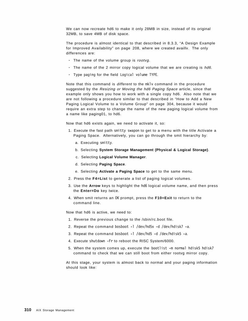
We can now recreate hd6 to make it only 28MB in size, instead of its original32MB, to save 4MB of disk space.
The procedure is almost identical to that described in 8.3.3, “A Design Examplefor Improved Availability” on page 208, where we created availlv. The onlydifferences are:
• The name of the volume group is rootvg.
• The name of the 2 mirror copy logical volume that we are creating is hd6.
• Type paging for the field Logical volume TYPE.
Note that this command is different to the mklv command in the proceduresuggested by the Resizing or Moving the hd6 Paging Space article, since thatexample only shows you how to work with a single copy hd6. Also note that weare not following a procedure similar to that described in “How to Add a NewPaging Logical Volume to a Volume Group” on page 304, because it wouldrequire an extra step to change the name of the new paging logical volume froma name like paging01, to hd6.
Now that hd6 exists again, we need to activate it, so:
1. Execute the fast path smitty swapon to get to a menu with the title Activate aPaging Space. Alternatively, you can go through the smit hierarchy by:
a. Executing smitty.
b. Selecting System Storage Management (Physical & Logical Storage) .
c. Selecting Logical Volume Manager .
d. Selecting Paging Space .
e. Selecting Activate a Paging Space to get to the same menu.
2. Press the F4=List to generate a list of paging logical volumes.
3. Use the Arrow keys to highlight the hd6 logical volume name, and then pressthe Enter=Do key twice.
4. When smit returns an OK prompt, press the F10=Exit to return to thecommand line.
Now that hd6 is active, we need to:
1. Reverse the previous change to the /sbin/rc.boot file.
2. Repeat the command bosboot -l /dev/hd5x -d /dev/hdisk7 -a.
3. Repeat the command bosboot -l /dev/hd5 -d /dev/hdisk5 -a.
4. Execute shutdown -Fr to reboot the RISC System/6000.
5. When the system comes up, execute the bootlist -m normal hdisk5 hdisk7command to check that we can still boot from either rootvg mirror copy.
At this stage, your system is almost back to normal and your paging informationshould look like:
310 AIX Storage Management
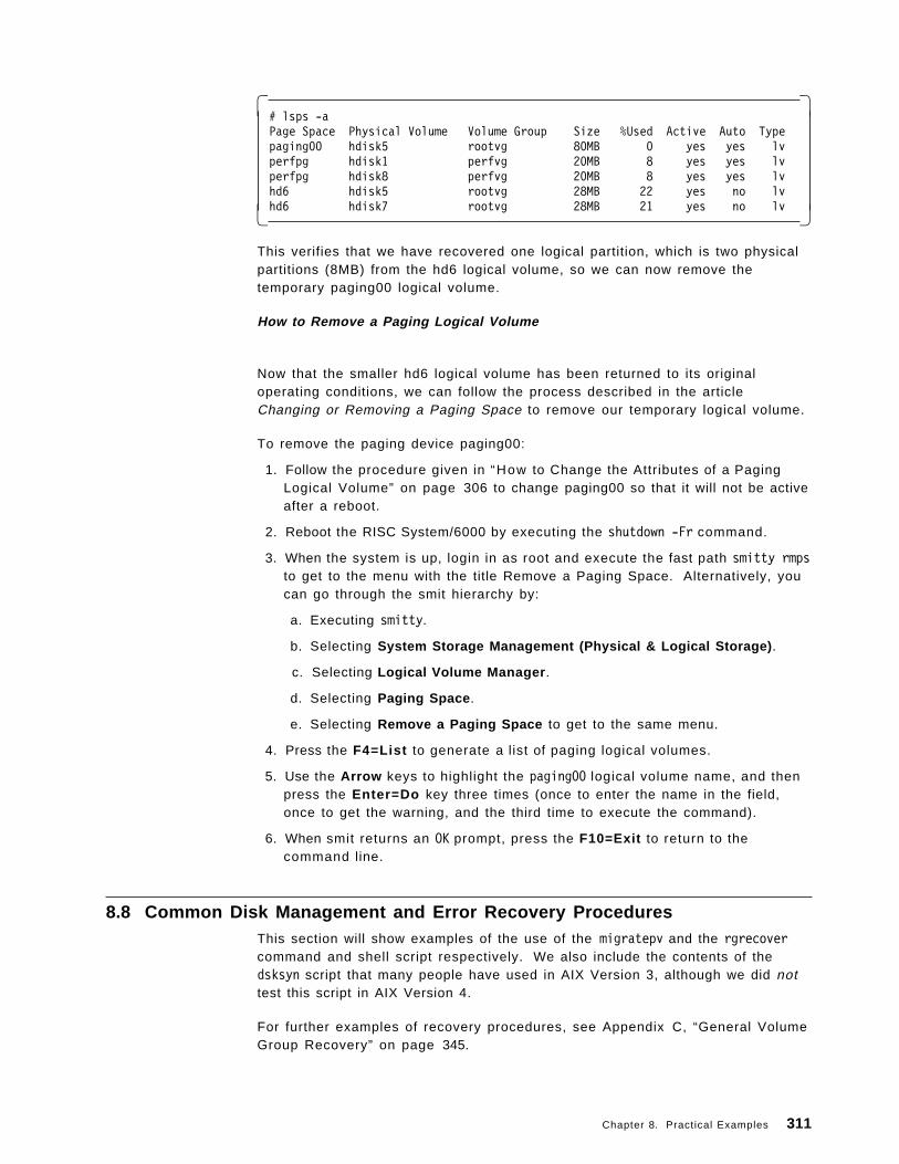
� �# lsps -aPage Space Physical Volume Volume Group Size %Used Active Auto Typepaging00 hdisk5 rootvg 80MB 0 yes yes lvperfpg hdisk1 perfvg 20MB 8 yes yes lvperfpg hdisk8 perfvg 20MB 8 yes yes lvhd6 hdisk5 rootvg 28MB 22 yes no lvhd6 hdisk7 rootvg 28MB 21 yes no lv� �
This verifies that we have recovered one logical partition, which is two physicalpartitions (8MB) from the hd6 logical volume, so we can now remove thetemporary paging00 logical volume.
How to Remove a Paging Logical Volume
Now that the smaller hd6 logical volume has been returned to its originaloperating conditions, we can follow the process described in the articleChanging or Removing a Paging Space to remove our temporary logical volume.
To remove the paging device paging00:
1. Follow the procedure given in “How to Change the Attributes of a PagingLogical Volume” on page 306 to change paging00 so that it will not be activeafter a reboot.
2. Reboot the RISC System/6000 by executing the shutdown -Fr command.
3. When the system is up, login in as root and execute the fast path smitty rmpsto get to the menu with the title Remove a Paging Space. Alternatively, youcan go through the smit hierarchy by:
a. Executing smitty.
b. Selecting System Storage Management (Physical & Logical Storage) .
c. Selecting Logical Volume Manager .
d. Selecting Paging Space .
e. Selecting Remove a Paging Space to get to the same menu.
4. Press the F4=List to generate a list of paging logical volumes.
5. Use the Arrow keys to highlight the paging00 logical volume name, and thenpress the Enter=Do key three times (once to enter the name in the field,once to get the warning, and the third time to execute the command).
6. When smit returns an OK prompt, press the F10=Exit to return to thecommand line.
8.8 Common Disk Management and Error Recovery ProceduresThis section will show examples of the use of the migratepv and the rgrecovercommand and shell script respectively. We also include the contents of thedsksyn script that many people have used in AIX Version 3, although we did nottest this script in AIX Version 4.
For further examples of recovery procedures, see Appendix C, “General VolumeGroup Recovery” on page 345.
Chapter 8. Practical Examples 311
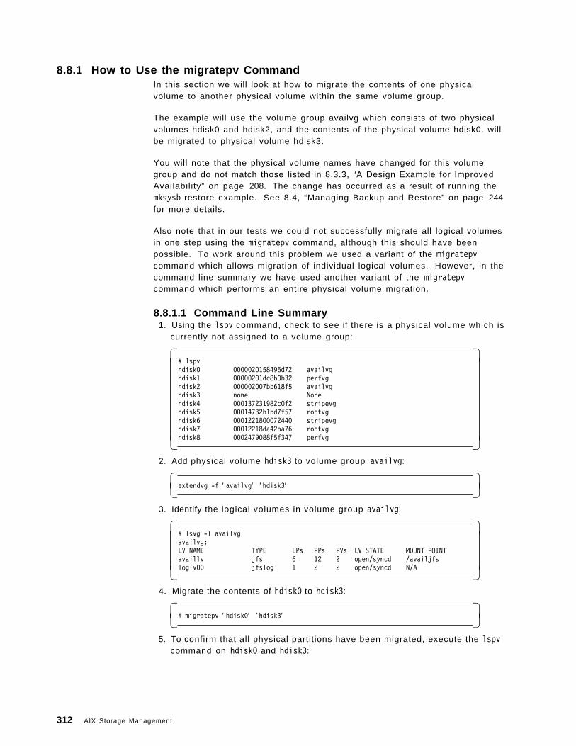
8.8.1 How to Use the migratepv CommandIn this section we will look at how to migrate the contents of one physicalvolume to another physical volume within the same volume group.
The example will use the volume group availvg which consists of two physicalvolumes hdisk0 and hdisk2, and the contents of the physical volume hdisk0. willbe migrated to physical volume hdisk3.
You will note that the physical volume names have changed for this volumegroup and do not match those listed in 8.3.3, “A Design Example for ImprovedAvailability” on page 208. The change has occurred as a result of running themksysb restore example. See 8.4, “Managing Backup and Restore” on page 244for more details.
Also note that in our tests we could not successfully migrate all logical volumesin one step using the migratepv command, although this should have beenpossible. To work around this problem we used a variant of the migratepvcommand which allows migration of individual logical volumes. However, in thecommand line summary we have used another variant of the migratepvcommand which performs an entire physical volume migration.
8.8.1.1 Command Line Summary 1. Using the lspv command, check to see if there is a physical volume which is
currently not assigned to a volume group:
� �# lspvhdisk0 0000020158496d72 availvghdisk1 00000201dc8b0b32 perfvghdisk2 000002007bb618f5 availvghdisk3 none Nonehdisk4 000137231982c0f2 stripevghdisk5 00014732b1bd7f57 rootvghdisk6 0001221800072440 stripevghdisk7 00012218da42ba76 rootvghdisk8 0002479088f5f347 perfvg� �
2. Add physical volume hdisk3 to volume group availvg:
� �extendvg -f ′ availvg′ ′ hdisk3′� �
3. Identify the logical volumes in volume group availvg:
� �# lsvg -l availvgavailvg:LV NAME TYPE LPs PPs PVs LV STATE MOUNT POINTavaillv jfs 6 12 2 open/syncd /availjfsloglv00 jfslog 1 2 2 open/syncd N/A� �
4. Migrate the contents of hdisk0 to hdisk3:
� �# migratepv ′ hdisk0′ ′ hdisk3′� �
5. To confirm that all physical partitions have been migrated, execute the lspvcommand on hdisk0 and hdisk3:
312 AIX Storage Management
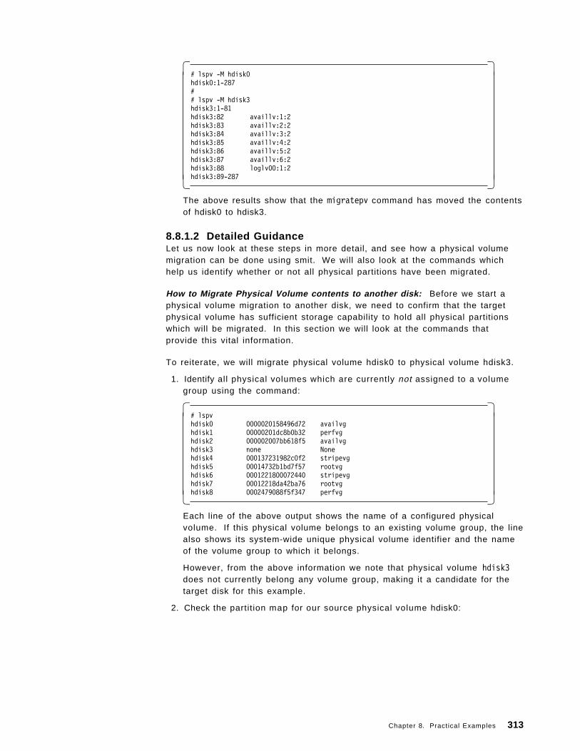
� �# lspv -M hdisk0hdisk0:1-287## lspv -M hdisk3hdisk3:1-81hdisk3:82 availlv:1:2hdisk3:83 availlv:2:2hdisk3:84 availlv:3:2hdisk3:85 availlv:4:2hdisk3:86 availlv:5:2hdisk3:87 availlv:6:2hdisk3:88 loglv00:1:2hdisk3:89-287� �
The above results show that the migratepv command has moved the contentsof hdisk0 to hdisk3.
8.8.1.2 Detailed GuidanceLet us now look at these steps in more detail, and see how a physical volumemigration can be done using smit. We will also look at the commands whichhelp us identify whether or not all physical partitions have been migrated.
How to Migrate Physical Volume contents to another disk: Before we start aphysical volume migration to another disk, we need to confirm that the targetphysical volume has sufficient storage capability to hold all physical partitionswhich will be migrated. In this section we will look at the commands thatprovide this vital information.
To reiterate, we will migrate physical volume hdisk0 to physical volume hdisk3.
1. Identify all physical volumes which are currently not assigned to a volumegroup using the command:
� �# lspvhdisk0 0000020158496d72 availvghdisk1 00000201dc8b0b32 perfvghdisk2 000002007bb618f5 availvghdisk3 none Nonehdisk4 000137231982c0f2 stripevghdisk5 00014732b1bd7f57 rootvghdisk6 0001221800072440 stripevghdisk7 00012218da42ba76 rootvghdisk8 0002479088f5f347 perfvg� �
Each line of the above output shows the name of a configured physicalvolume. If this physical volume belongs to an existing volume group, the linealso shows its system-wide unique physical volume identifier and the nameof the volume group to which it belongs.
However, from the above information we note that physical volume hdisk3does not currently belong any volume group, making it a candidate for thetarget disk for this example.
2. Check the partition map for our source physical volume hdisk0:
Chapter 8. Practical Examples 313
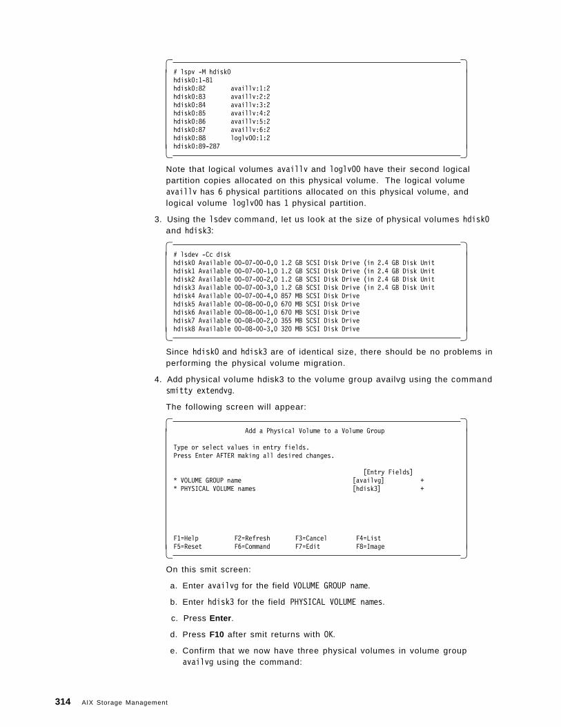
� �# lspv -M hdisk0hdisk0:1-81hdisk0:82 availlv:1:2hdisk0:83 availlv:2:2hdisk0:84 availlv:3:2hdisk0:85 availlv:4:2hdisk0:86 availlv:5:2hdisk0:87 availlv:6:2hdisk0:88 loglv00:1:2hdisk0:89-287� �
Note that logical volumes availlv and loglv00 have their second logicalpartition copies allocated on this physical volume. The logical volumeavaillv has 6 physical partitions allocated on this physical volume, andlogical volume loglv00 has 1 physical partition.
3. Using the lsdev command, let us look at the size of physical volumes hdisk0and hdisk3:
� �# lsdev -Cc diskhdisk0 Available 00-07-00-0,0 1.2 GB SCSI Disk Drive (in 2.4 GB Disk Unithdisk1 Available 00-07-00-1,0 1.2 GB SCSI Disk Drive (in 2.4 GB Disk Unithdisk2 Available 00-07-00-2,0 1.2 GB SCSI Disk Drive (in 2.4 GB Disk Unithdisk3 Available 00-07-00-3,0 1.2 GB SCSI Disk Drive (in 2.4 GB Disk Unithdisk4 Available 00-07-00-4,0 857 MB SCSI Disk Drivehdisk5 Available 00-08-00-0,0 670 MB SCSI Disk Drivehdisk6 Available 00-08-00-1,0 670 MB SCSI Disk Drivehdisk7 Available 00-08-00-2,0 355 MB SCSI Disk Drivehdisk8 Available 00-08-00-3,0 320 MB SCSI Disk Drive� �
Since hdisk0 and hdisk3 are of identical size, there should be no problems inperforming the physical volume migration.
4. Add physical volume hdisk3 to the volume group availvg using the commandsmitty extendvg.
The following screen will appear:
� �Add a Physical Volume to a Volume Group
Type or select values in entry fields.Press Enter AFTER making all desired changes.
[Entry Fields]* VOLUME GROUP name [availvg] +* PHYSICAL VOLUME names [hdisk3] +
F1=Help F2=Refresh F3=Cancel F4=ListF5=Reset F6=Command F7=Edit F8=Image� �
On this smit screen:
a. Enter availvg for the field VOLUME GROUP name.
b. Enter hdisk3 for the field PHYSICAL VOLUME names.
c. Press Enter .
d. Press F10 after smit returns with OK.
e. Confirm that we now have three physical volumes in volume groupavailvg using the command:
314 AIX Storage Management
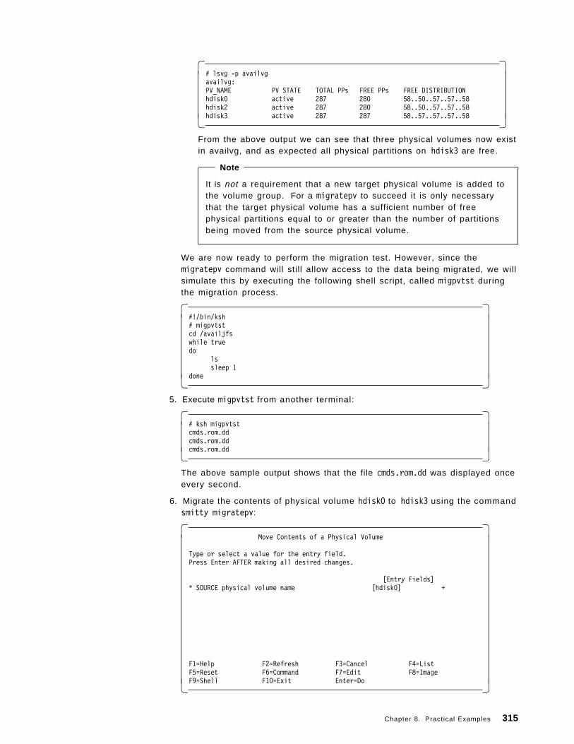
� �# lsvg -p availvgavailvg:PV_NAME PV STATE TOTAL PPs FREE PPs FREE DISTRIBUTIONhdisk0 active 287 280 58..50..57..57..58hdisk2 active 287 280 58..50..57..57..58hdisk3 active 287 287 58..57..57..57..58� �
From the above output we can see that three physical volumes now existin availvg, and as expected all physical partitions on hdisk3 are free.
Note
It is not a requirement that a new target physical volume is added tothe volume group. For a migratepv to succeed it is only necessarythat the target physical volume has a sufficient number of freephysical partitions equal to or greater than the number of partitionsbeing moved from the source physical volume.
We are now ready to perform the migration test. However, since themigratepv command will still allow access to the data being migrated, we willsimulate this by executing the following shell script, called migpvtst duringthe migration process.
� �#!/bin/ksh# migpvtstcd /availjfswhile truedo
lssleep 1
done� � 5. Execute migpvtst from another terminal:
� �# ksh migpvtstcmds.rom.ddcmds.rom.ddcmds.rom.dd� �
The above sample output shows that the file cmds.rom.dd was displayed onceevery second.
6. Migrate the contents of physical volume hdisk0 to hdisk3 using the commandsmitty migratepv:
� �Move Contents of a Physical Volume
Type or select a value for the entry field.Press Enter AFTER making all desired changes.
[Entry Fields]* SOURCE physical volume name [hdisk0] +
F1=Help F2=Refresh F3=Cancel F4=ListF5=Reset F6=Command F7=Edit F8=ImageF9=Shell F10=Exit Enter=Do� �
Chapter 8. Practical Examples 315
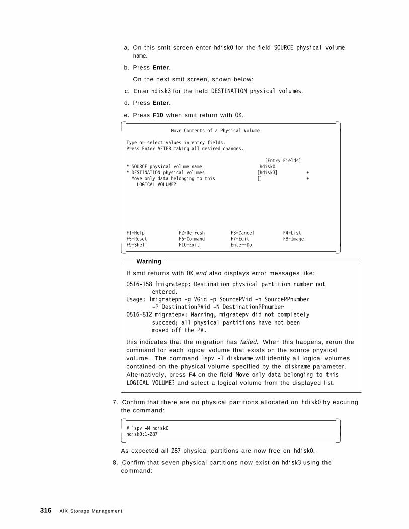
a. On this smit screen enter hdisk0 for the field SOURCE physical volumename.
b. Press Enter .
On the next smit screen, shown below:
c. Enter hdisk3 for the field DESTINATION physical volumes.
d. Press Enter .
e. Press F10 when smit return with OK.
� �Move Contents of a Physical Volume
Type or select values in entry fields.Press Enter AFTER making all desired changes.
[Entry Fields]* SOURCE physical volume name hdisk0* DESTINATION physical volumes [hdisk3] +Move only data belonging to this [] +LOGICAL VOLUME?
F1=Help F2=Refresh F3=Cancel F4=ListF5=Reset F6=Command F7=Edit F8=ImageF9=Shell F10=Exit Enter=Do� �
Warning
If smit returns with OK and also displays error messages like:
0516-158 lmigratepp: Destination physical partition number notentered.
Usage: lmigratepp -g VGid -p SourcePVid -n SourcePPnumber-P DestinationPVid -N DestinationPPnumber
0516-812 migratepv: Warning, migratepv did not completelysucceed; all physical partitions have not beenmoved off the PV.
this indicates that the migration has failed. When this happens, rerun thecommand for each logical volume that exists on the source physicalvolume. The command lspv -l diskname will identify all logical volumescontained on the physical volume specified by the diskname parameter.Alternatively, press F4 on the field Move only data belonging to thisLOGICAL VOLUME? and select a logical volume from the displayed list.
7. Confirm that there are no physical partitions allocated on hdisk0 by excutingthe command:
� �# lspv -M hdisk0hdisk0:1-287� �
As expected all 287 physical partitions are now free on hdisk0.
8. Confirm that seven physical partitions now exist on hdisk3 using thecommand:
316 AIX Storage Management
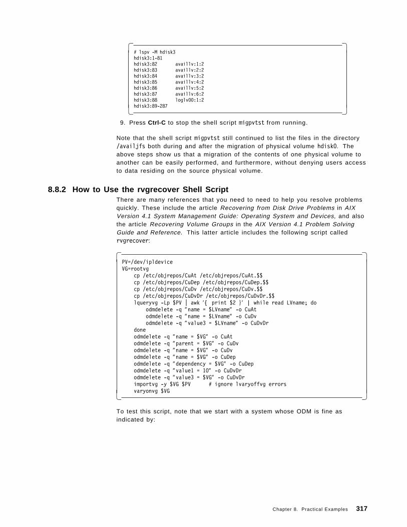
� �# lspv -M hdisk3hdisk3:1-81hdisk3:82 availlv:1:2hdisk3:83 availlv:2:2hdisk3:84 availlv:3:2hdisk3:85 availlv:4:2hdisk3:86 availlv:5:2hdisk3:87 availlv:6:2hdisk3:88 loglv00:1:2hdisk3:89-287� �
9. Press Ctrl-C to stop the shell script migpvtst from running.
Note that the shell script migpvtst still continued to list the files in the directory/availjfs both during and after the migration of physical volume hdisk0. Theabove steps show us that a migration of the contents of one physical volume toanother can be easily performed, and furthermore, without denying users accessto data residing on the source physical volume.
8.8.2 How to Use the rvgrecover Shell ScriptThere are many references that you need to need to help you resolve problemsquickly. These include the article Recovering from Disk Drive Problems in AIXVersion 4.1 System Management Guide: Operating System and Devices, and alsothe article Recovering Volume Groups in the AIX Version 4.1 Problem SolvingGuide and Reference. This latter article includes the following script calledrvgrecover:
� �PV=/dev/ipldeviceVG=rootvg
cp /etc/objrepos/CuAt /etc/objrepos/CuAt.$$cp /etc/objrepos/CuDep /etc/objrepos/CuDep.$$cp /etc/objrepos/CuDv /etc/objrepos/CuDv.$$cp /etc/objrepos/CuDvDr /etc/objrepos/CuDvDr.$$lqueryvg -Lp $PV | awk ′{ print $2 }′ | while read LVname; do
odmdelete -q ″name = $LVname″ -o CuAtodmdelete -q ″name = $LVname″ -o CuDvodmdelete -q ″value3 = $LVname″ -o CuDvDr
doneodmdelete -q ″name = $VG″ -o CuAtodmdelete -q ″parent = $VG″ -o CuDvodmdelete -q ″name = $VG″ -o CuDvodmdelete -q ″name = $VG″ -o CuDepodmdelete -q ″dependency = $VG″ -o CuDepodmdelete -q ″value1 = 10″ -o CuDvDrodmdelete -q ″value3 = $VG″ -o CuDvDrimportvg -y $VG $PV # ignore lvaryoffvg errorsvaryonvg $VG� �
To test this script, note that we start with a system whose ODM is fine asindicated by:
Chapter 8. Practical Examples 317
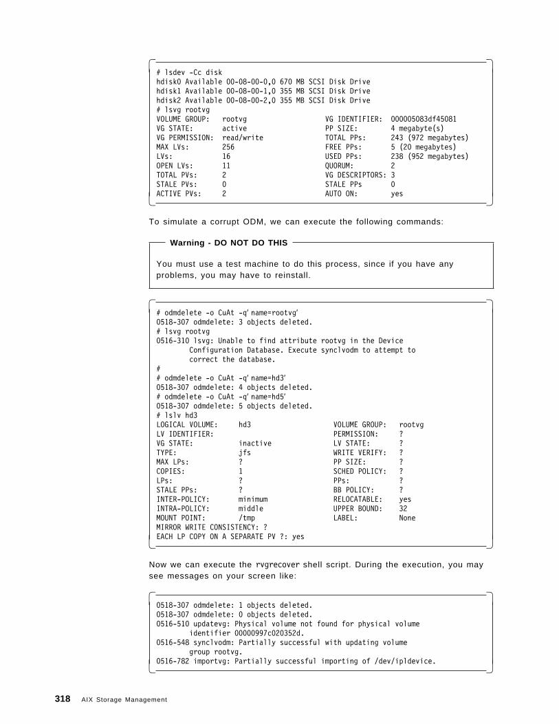
� �# lsdev -Cc diskhdisk0 Available 00-08-00-0,0 670 MB SCSI Disk Drivehdisk1 Available 00-08-00-1,0 355 MB SCSI Disk Drivehdisk2 Available 00-08-00-2,0 355 MB SCSI Disk Drive# lsvg rootvgVOLUME GROUP: rootvg VG IDENTIFIER: 000005083df45081VG STATE: active PP SIZE: 4 megabyte(s)VG PERMISSION: read/write TOTAL PPs: 243 (972 megabytes)MAX LVs: 256 FREE PPs: 5 (20 megabytes)LVs: 16 USED PPs: 238 (952 megabytes)OPEN LVs: 11 QUORUM: 2TOTAL PVs: 2 VG DESCRIPTORS: 3STALE PVs: 0 STALE PPs 0ACTIVE PVs: 2 AUTO ON: yes� �
To simulate a corrupt ODM, we can execute the following commands:
Warning - DO NOT DO THIS
You must use a test machine to do this process, since if you have anyproblems, you may have to reinstall.
� �# odmdelete -o CuAt -q′ name=rootvg′0518-307 odmdelete: 3 objects deleted.# lsvg rootvg0516-310 lsvg: Unable to find attribute rootvg in the Device
Configuration Database. Execute synclvodm to attempt tocorrect the database.
## odmdelete -o CuAt -q′ name=hd3′0518-307 odmdelete: 4 objects deleted.# odmdelete -o CuAt -q′ name=hd5′0518-307 odmdelete: 5 objects deleted.# lslv hd3LOGICAL VOLUME: hd3 VOLUME GROUP: rootvgLV IDENTIFIER: PERMISSION: ?VG STATE: inactive LV STATE: ?TYPE: jfs WRITE VERIFY: ?MAX LPs: ? PP SIZE: ?COPIES: 1 SCHED POLICY: ?LPs: ? PPs: ?STALE PPs: ? BB POLICY: ?INTER-POLICY: minimum RELOCATABLE: yesINTRA-POLICY: middle UPPER BOUND: 32MOUNT POINT: /tmp LABEL: NoneMIRROR WRITE CONSISTENCY: ?EACH LP COPY ON A SEPARATE PV ?: yes� �
Now we can execute the rvgrecover shell script. During the execution, you maysee messages on your screen like:
� �0518-307 odmdelete: 1 objects deleted.0518-307 odmdelete: 0 objects deleted.0516-510 updatevg: Physical volume not found for physical volume
identifier 00000997c020352d.0516-548 synclvodm: Partially successful with updating volume
group rootvg.0516-782 importvg: Partially successful importing of /dev/ipldevice.� �
318 AIX Storage Management
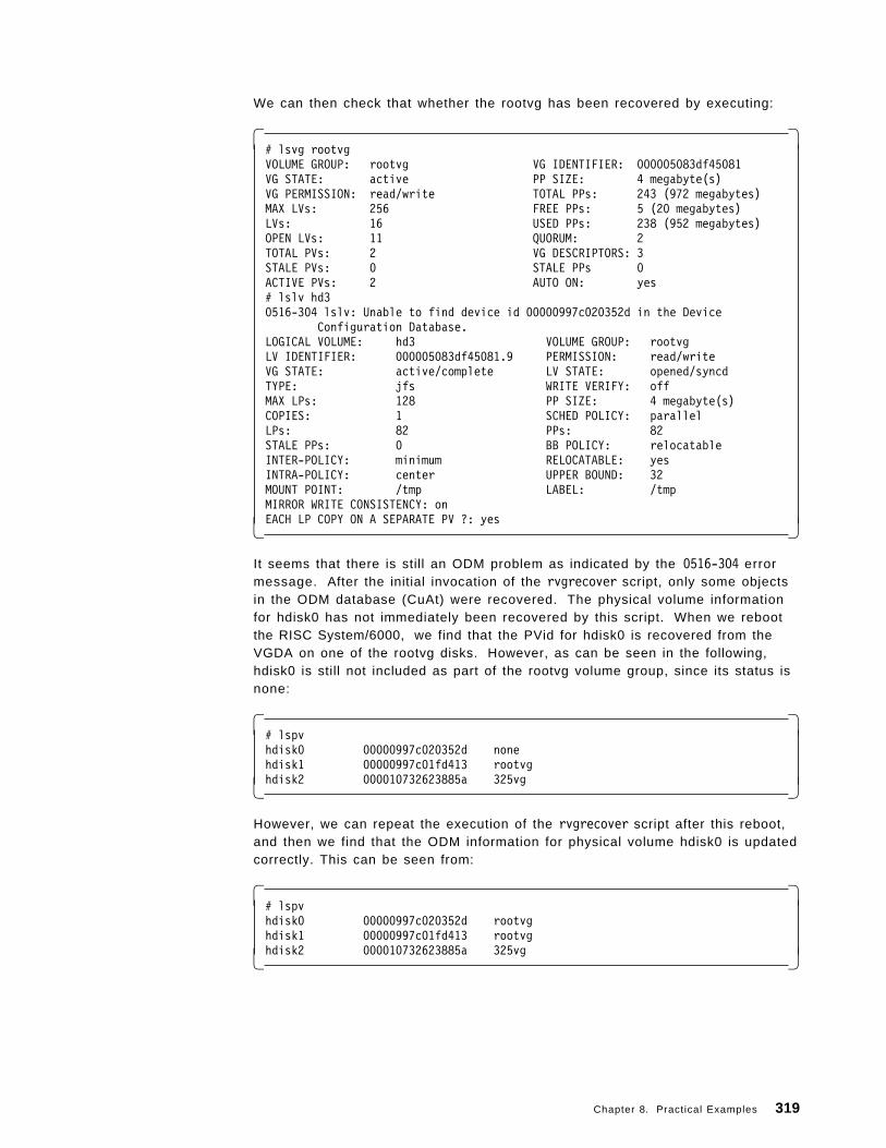
We can then check that whether the rootvg has been recovered by executing:
� �# lsvg rootvgVOLUME GROUP: rootvg VG IDENTIFIER: 000005083df45081VG STATE: active PP SIZE: 4 megabyte(s)VG PERMISSION: read/write TOTAL PPs: 243 (972 megabytes)MAX LVs: 256 FREE PPs: 5 (20 megabytes)LVs: 16 USED PPs: 238 (952 megabytes)OPEN LVs: 11 QUORUM: 2TOTAL PVs: 2 VG DESCRIPTORS: 3STALE PVs: 0 STALE PPs 0ACTIVE PVs: 2 AUTO ON: yes# lslv hd30516-304 lslv: Unable to find device id 00000997c020352d in the Device
Configuration Database.LOGICAL VOLUME: hd3 VOLUME GROUP: rootvgLV IDENTIFIER: 000005083df45081.9 PERMISSION: read/writeVG STATE: active/complete LV STATE: opened/syncdTYPE: jfs WRITE VERIFY: offMAX LPs: 128 PP SIZE: 4 megabyte(s)COPIES: 1 SCHED POLICY: parallelLPs: 82 PPs: 82STALE PPs: 0 BB POLICY: relocatableINTER-POLICY: minimum RELOCATABLE: yesINTRA-POLICY: center UPPER BOUND: 32MOUNT POINT: /tmp LABEL: /tmpMIRROR WRITE CONSISTENCY: onEACH LP COPY ON A SEPARATE PV ?: yes� �
It seems that there is still an ODM problem as indicated by the 0516-304 errormessage. After the initial invocation of the rvgrecover script, only some objectsin the ODM database (CuAt) were recovered. The physical volume informationfor hdisk0 has not immediately been recovered by this script. When we rebootthe RISC System/6000, we find that the PVid for hdisk0 is recovered from theVGDA on one of the rootvg disks. However, as can be seen in the following,hdisk0 is still not included as part of the rootvg volume group, since its status isnone:
� �# lspvhdisk0 00000997c020352d nonehdisk1 00000997c01fd413 rootvghdisk2 000010732623885a 325vg� �
However, we can repeat the execution of the rvgrecover script after this reboot,and then we find that the ODM information for physical volume hdisk0 is updatedcorrectly. This can be seen from:
� �# lspvhdisk0 00000997c020352d rootvghdisk1 00000997c01fd413 rootvghdisk2 000010732623885a 325vg� �
Chapter 8. Practical Examples 319
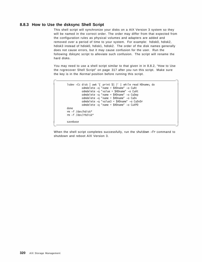
8.8.3 How to Use the dsksync Shell ScriptThis shell script will synchronize your disks on a AIX Version 3 system so theywill be named in the correct order. The order may differ from that expected fromthe configuration rules as physical volumes and adapters are added andremoved over a period of time to your system. For example: hdisk0, hdisk2,hdisk3 instead of hdisk0, hdisk1, hdisk2. The order of the disk names generallydoes not cause errors, but it may cause confusion for the user. Run thefollowing dsksync script to alleviate such confusion. The script will rename thehard disks.
You may need to use a shell script similar to that given in in 8.8.2, “How to Usethe rvgrecover Shell Script” on page 317 after you run this script. Make surethe key is in the Normal position before running this script.
� �lsdev -Cc disk | awk ′{ print $1 }′ | while read HDname; do
odmdelete -q ″name = $HDname″ -o CuAtodmdelete -q ″value = $HDname″ -o CuAtodmdelete -q ″name = $HDname″ -o CuDepodmdelete -q ″name = $HDname″ -o CuDvodmdelete -q ″value3 = $HDname″ -o CuDvDrodmdelete -q ″name = $HDname″ -o CuVPD
donerm -f /dev/hdisk*rm -f /dev/rhdisk*
savebase� �
When the shell script completes successfully, run the shutdown -Fr command toshutdown and reboot AIX Version 3.
320 AIX Storage Management
Appendix A. Overview of Hardware Components
This appendix contains highlights of hardware storage components available onthe RS/6000.
A.1 Storage Product Interface AdaptersThis section looks at the hardware adapters available to connect varioushardware storage components to the RS/6000 system units.
A.1.1 SCSI AdaptersThe following are examples of SCSI adapters that are available to connect SCSIdevices to the RS/6000.
A.1.1.1 IBM SCSI High Performance I/O ControllerThis Micro Channel adapter occupies one slot in the RS/6000 and provides:
• One SCSI internal and/or external bus interface
• 4MB/sec maximum synchronous data transfer
• 2MB/sec maximum asynchronous data transfer
• One byte wide single-ended implementation
• Maximum bus length of six meters
This adapter is supported in the following systems:
• #2828
− RS/6000 Models 320, 32H, 32E
• #2829
− RS/6000 500 series, all models
• #2835
− RS/6000 200 series, all models except 250, 25S, 25W, 25T
− RS/6000 300 series, all models
− RS/6000 500 series, all models
− RS/6000 900 and R series, all models
A.1.1.2 IBM SCSI-2 High Performance I/O ControllerThis Micro Channel adapter occupies one slot in the RS/6000 and provides:
• One SCSI-2 internal and/or external interface
• 10MB/sec maximum synchronous data transfer
• 2.5MB/sec maximum asynchronous data transfer
• One byte wide single-ended implementation
• Maximum bus length of three to six meters, depending upon configuration
• Command Tag Queueing
This adapter is supported in the following systems:
Copyright IBM Corp. 1994 321
• #2410
− RS/6000 200 series, all models
− RS/6000 Models 41T, 41W
− RS/6000 Model C10
− RS/6000 300 series, all models
− RS/6000 500 series, all models except 520, 530, 540
− RS/6000 900 and R series, all models except 930
• #2831
− RS/6000 500 series, all models except 520, 530, 540
A.1.1.3 IBM SCSI-2 Differential High Performance External I/OControllerThis Micro Channel adapter occupies one slot in the RS/6000 and provides:
• One SCSI-2 internal and/or external bus interface
• 10MB/sec maximum synchronous data transfer
• 2.5MB/sec maximum asynchronous data transfer
• One byte wide differential interface
• Maximum bus length of 19 meters
• Command Tag Queueing
This adapter is supported in the following systems:
• #2420
− RS/6000 200 series, all models except 250, 25S, 25W, 25T
− RS/6000 models 41T, 41W
− RS/6000 model C10
− RS/6000 model 3AT, 3BT
− RS/6000 300 series, all models except 320, 32H, 32E
− RS/6000 500 series, all models except 520, 530, 540
− RS/6000 900 and R series, all models except 930
A.1.1.4 IBM SC SI-2 Fast/Wide Adapter/AThis Micro Channel adapter occupies one slot in the RS/6000 and provides:
• Two independent SCSI-2 bus interfaces, one internal, one external
• 20MB/sec maximum synchronous transfer rate
• 3.6MB/sec maximum asynchronous transfer rate
• Two byte wide single-ended implementation
• Maximum bus length of three to six meters, depending upon busconfiguration
• Command Tag Queueing
• Up to 30 total SCSI device addresses, 15 internal, and 15 external. Thiscapability is currently limited by AIX to 14 total addresses, 7 internal, and 7external
322 AIX Storage Management
This adapter is supported in the following systems:
• #2415
− RS/6000 models 250, 25S, 25W, 25T
− RS/6000 models 41T, 41W
− RS/6000 model C10
− RS/6000 300 series, all models except 320
− RS/6000 500 series, all models except 520, 530, 540
− RS/6000 900 and R series, all models except 930
A.1.1.5 IBM SCSI-2 Differential Fast/Wide Adapter/AThis Micro Channel adapter occupies one slot in the RS/6000 and provides:
• Two independent SCSI-2 bus interfaces, one internal, one external
• 20MB/sec maximum synchronous data transfer
• 3.6MB/sec maximum asynchronous data transfer
• Maximum bus length of three to six meters, depending on internal busconfiguration
• Maximum bus length of 25 meters, depending on external bus configuration
• Command Tag Queueing
• Two byte wide single-ended implementation, internal bus
• Two byte wide differential implementation, external bus
• Up to 30 total SCSI device addresses, 15 internal, and 15 external. Thiscapability is currently limited by AIX to a total of 14 addresses, 7 internal,and 7 external
This adapter is supported in the following systems:
• #2416
− RS/6000 models 250, 25S, 25W, 25T
− RS/6000 models 41T, 41W
− RS.6000 model C10
− RS/6000 300 series, all models except 320
− RS/6000 500 series, all models except 520, 530, 540
− RS/6000 900 and R series, all models except 930
A.1.1.6 Integrated IBM SCSI High-Performance I/O ControllerThis integrated controller provides the following capabilities:
• One SCSI internal and/or external bus interface
• 4MB/sec maximum synchronous data transfer
• 2MB/sec maximum asynchronous data transfer
• One byte wide single-ended implementation
• Maximum bus length of six meters
The controller is integrated into the following models:
Appendix A. Overview of Hardware Components 323
• RS/6000 models 340, 34H, 350, 355, 360, 365, 370, 37T, 375
• RS/6000 500 series, 570 and above
• RS/6000 900 and R series 970 and above, R10, R20
A.1.1.7 Integrated SCSI ControllerThis integrated controller provides:
• One SCSI internal and/or external bus interface
• 5MB/sec maximum synchronous data transfer
• 5MB/sec maximum asynchronous data transfer
• One byte wide single-ended implementation
• Maximum bus length of six meters
The controller is integrated into the following models:
• RS/6000 model M20
• RS/6000 200 series, all models except 250, 25S, 25T, 25W
A.1.1.8 Integrated SCSI-2 ControllerThis integrated controller provides:
• One SCSI-2 internal and/or external bus interface
• 10MB/sec maximum synchronous data transfer
• 5MB/sec maximum asynchronous data transfer
• One byte wide single-ended implementation
• Maximum bus length for models 250, 25S, 25T, 25W:
− Three meters at SCSI-2 data rates (5 - 10MB/sec)
− Six meters at SCSI data rates (<5MB/sec)
• Maximum bus length for models 41T, 41W, C10
− Bus length limited to 2.3 meters external to the system
A.1.1.9 Integrated IBM SCSI-2 Fast/Wide Adapter/AThis adapter provides the following capabilities:
• Two independent SCSI-2 bus interfaces, one internal, one external
• 20MB/sec maximum synchronous data transfer rate
• 3.6MB/sec maximum asynchronous data transfer rate
• Maximum bus length of three to six meters, depending upon busconfiguration
• Command Tag Queueing
• Two byte wide single-ended implementation. Up to 30 total SCSI deviceaddresses, 15 internal, and 15 external. This capability is currently limited byAIX to a total of 14 addresses, 7 internal, and 7 external
This adapter is integrated into the following models:
• RS/6000 300 series, models 380, 390, 3AT, 3BT
324 AIX Storage Management
A.1.2 Serial AdaptersThe following are examples of serial adapters that can be used to attach serialdevices to the RS/6000.
A.1.2.1 High Performance Disk Drive Subsystem AdapterThis Micro Channel adapter occupies one slot on the RS/6000 and provides:
• Support for up to four 9333 subsystems
• Support for up to 16 serial disk drives per adapter
• 8MB/sec full duplex operation with packet multiplexing allowing concurrentcommunication with all attached devices
• Maximum cable length of 10 meters
The adapter is supported in the following systems:
• #6212
− RS/6000 200 series, all models
− RS/6000 model C10
− RS/6000 300 series, all models
− RS/6000 500 series, all models
− RS/6000 900 and R series, all models
A.1.3 HiPPI AdaptersThe following adapter can be used to attache HiPPI compatible devices to theRS/6000.
A.1.3.1 HiPPI AdapterThis Micro Channel adapter occupies 3 adjacent slots in the RS/6000, though dueto power constraints, must be considered to occupy 5 slots. It provides:
• Peak rate simplex/duplex data transfer up to 800Mb/sec in each direction
• Maximum cable length of 25 meters (extendable via vendor switches andfibre optic extenders)
• Connection to the 9570 Disk Array Subsystem
The adapter is supported in the following systems:
• #2735
− RS/6000 500 series, models 570, 580, 58H, 590, 59H
− RS/6000 900 and R series, models 970, 97B, 980, 98B, 990, R24
A.1.4 ESCON AdaptersThe following adapter can be used to attach ESCON* compatible devices to theRS/6000.
Appendix A. Overview of Hardware Components 325
A.1.4.1 System/390 ESCON Channel EmulatorThis Micro Channel adapter requires 2 slots on the RS/6000 and provides:
• 17MB/sec data transfer rate
• Support for attachment to all models of the 3490 and 3490E tape subsystems
• Support for attachment to the 3494 and 3495 tape library dataservers
This adapter is supported by the following systems:
• #2754
− RS/6000 models 340, 34H, 350, 360, 36T, 370, 37T
− RS/6000 models 3AT, 3BT
− RS/6000 500 series, all models
− RS/6000 900 and R series, all models
A.1.5 Channel Emulation AdaptersThe following adapter can be used to attach channel compatible devices to theRS/6000.
A.1.5.1 System/370 Channel Emulator/AThis Micro Channel adapter requires one slot in an RS/6000 and provides:
• 4.5MB/sec data transfer rate
• Support for up to 4 control units per block multiplexer channel
• Maximum cable length of 61 meters
• Support for all models of the 3480, 3490 and 3490E tape subsystems
• Support for the 3495 tape library dataserver
The adapter is supported in the following systems:
• #2759
− RS/6000 300 series, all models
− RS/6000 models 3AT, 3BT
− RS/6000 500 series, all models
− RS/6000 900 and R series, all models
A.2 Disk Storage ProductsThis section looks at the disk storage products that are available for attachmentto the RS/6000.
A.2.1 Disk DrivesThe following drive units can be installed.
326 AIX Storage Management
A.2.1.1 SCSI Drives3.5″ Drives: The following drives are available. They are SCSI-2 single-endedunless otherwise specified.
• #2490 - 200MB, supported on 200, 300 series
• #2560 - 400MB (SCSI), supported on 200, 300 series
• #2390 - 540MB, supported on 200, 300 series
• #2555 - 1.0GB, supported on 200, 300, 500, 900 series
• #2565 - 1.0GB (differential), supported on 9334
• #2580 - 2.0GB, supported on 200, 300, 500, 900 series
• #2585 - 2.0GB (differential), supported on 9334
5.25″ Drives: The following drives are available:
• #2570 - 1.37GB (SCSI), supported on 500 series and 9334
• #2590 - 2.4GB (SCSI-2), supported on 500 series and 9334
A.2.1.2 Serial DrivesThe following drives are available:
• #3100 - 857MB (5.25″), supported on 9333
• #3110 - 1.07GB (5.25″), supported on 9333
• #3120 - 2.0GB (3.5″), supported on 9333
A.2.2 Disk SubsystemsThe following disk subsystems can be attached to the RS/6000.
A.2.2.1 IBM 7203 and 7204 External Disk DrivesThe 7203 provides an external disk drive supporting a removable disk pack ofeither 355MB or 1.0GB. This is useful for environments where security is anissue, as the disk pack can be removed and stored in a secure place. Disk packscan also be moved between machines, allowing easy sharing of information. The7203 supports a standard SCSI interface, and is attachable to all systems.
The 7204 is an external disk unit supporting the following capacities:
• Model 320 - 320MB, SCSI-2 interface, supported on 200, 300, 500, 900 series
• Model 001 - 1.0GB, SCSI-2 interface, supported on 200, 300, 500, 900 series
• Model 010 - 1.0GB, SCSI-2 interface, supported on 200, 300, 500, 900 series,this unit has faster access times
• Model 215 - 2.0GB, SCSI-2 differential interface, supported on 300, 500, 900series
A.2.2.2 IBM 9334 SCSI Expansion UnitThe 9334 SCSI Expansion Unit provides support for up to four SCSI disk drivesper unit. There are four models:
• Model 010 (SCSI-2), rack mounted, supported by the 900 series
• Model 011 (SCSI-2 differential), rack mounted, supported by the 900 series
• Model 500 (SCSI-2), desk side, supported by the 200, 300, 500 series
Appendix A. Overview of Hardware Components 327
• Model 501 (SCSI-2 differential), desk side, supported by the 300, 500 series
A.2.2.3 IBM 9333 High Performance Disk Drive SubsystemThe 9333 High Performance Disk Drive Subsystem attaches to a port on the HighPerformance Disk Drive Subsystem adapter, and supports up to four serial disks.The 9333 is designed to provide the fastest response time when an applicationmakes large numbers of requests for short blocks of data.
The 9333 also supports multiple paths from its controller to the processor,allowing a 9333 to attach simultaneously to up to eight hosts processors. This isuseful for high availability environments or data sharing. Independent electricalpaths are provided to each host, so bandwidth is not shared, nor will electricalfailure in one path affect the others.
There are four models of the 9333:
• Model 010 - rack mounted, supported by the 900 series (4.3GB max)
• Model 011 - rack mounted, supported by the 900 series (8.0GB max)
• Model 500 - desk side, supported by 34H, 360, 370, and 500 series (4.3 GBmax)
• Model 501 - desk side, supported by 34H, 360, 370, and 500 series (8.0 GBmax)
A.2.2.4 IBM 7134 High Density SCSI Disk SubsystemThe 7134 High Density SCSI Disk Subsystem can hold 16 3.5″ 2.0GB SCSI diskdrives. These drives are split into two banks of eight drives, each on a separateinternal (to the 7134) SCSI adapter. The 7134 itself requires a SCSI-2 differentialfast/wide adapter to attach to the system. The subsystem can be connected totwo hosts for availability reasons, and in this case, only six drives are supportedin each bank.
There is one model of the 7134:
• Model 010 - rack mounted, supported by the 300, 500, 900, and R series
A.2.2.5 IBM 7135 RAIDiant ArrayThe 7135 RAIDiant Array provides high data availability and/or performanceusing RAID technology (RAID is explained in 2.2.2.2, “Selecting the Correct DiskStorage Devices” on page 27); RAID levels 0, 1, 3, and 5 are supported.Essentially any combination of RAID levels are concurrently supported on the7135, with the Logical Unit, or LUN of disks supporting each defined RAID levelappearing as a single SCSI disk drive to the operating system.
The 7135 is connected to the host system via either a SCSI-2 differential adapter,or a SCSI-2 fast/wide differential adapter. The disks are connected internally tofive SCSI-2 buses, giving a maximum number of 30 disks; either 2.0GB, or 1.3GB3.5″ disks are supported.
The 7135 has an internal controller that manages the RAID functions, and asecond controller may be added operating in either standby mode (taking over inthe event of failure of the first), or in active mode (providing enhancedperformance as well as availability). In addition, redundant power supplies andcooling are standard, and maintenance is supported concurrently on any failinghardware.
328 AIX Storage Management
There are two models of the 7135:
• Model 010 (system rack), up to 12 disks, supported by 300, 500, 900, and Rseries
• Model 110 (desk side), up to 30 disks, supported by 300, 500, 900, and Rseries.
A.2.2.6 IBM 3514 High Availability Disk ArrayThe 3514 Disk Array provides a lower cost solution for those environments notrequiring the full range of RAID support. The 3514 allows a maximum of eightdisk drives, which can be either 1.0GB or 2.0GB (not mixed within the same unit).RAID levels 0 and 5 are supported, configurable from the front panel of the unit.All drives within the 3514 are used in the configured RAID level, and appear tothe operating system as a single SCSI disk drive (one drive can be designated ata hot spare, to be used automatically in the event of failure of one of the otherdrives).
The 3514 is connected to the host system via a SCSI-2 fast/wide differentialadapter, or a SCSI-2 differential adapter; internally, the disks are connected tothe array controller via four SCSI-2 buses.
A redundant power supply is provided, but not cooling fans, or controller.
There are four models of the 3514:
• Model 212 (desk side), 1.0GB disks, supported by 250, 300 series, and 500series
• Model 213 (desk side), 2.0GB disks, supported by 250, 300 series, and 500series
• Model 312 (rack mount), 1.0GB disks, supported by 250, 300 series, and 500series
• Model 313 (rack mount), 2.0GB disks, supported by 250, 300 series, and 500series
A.2.2.7 IBM 9570 Disk Array SubsystemThe 9570 Disk Array is designed to support applications requiring very highperformance access to information, and/or enhanced availability. The 9570 R5supports RAID levels 1 and 5 concurrently within a system in separately definedpartitions. The internal disks are 2.0GB SCSI disks supporting IPI-2 protocols,and are supported in configurations ranging from 12.9GB to 232.4GB of data.
The 9570 is connected to the host system via the HiPPI adapter, and can supporta maximum sustained data transfer rate of over 60MB/sec.
Fault tolerance is provided in the form of redundant power supplies and cooling.The subsystem also provides its own console for error detection, collection andmonitoring. Automatic log analysis and real time fault isolation can beperformed.
The 9570 is rack based and there are many models depending upon the exactconfiguration required. The first rack in a subsystem will always contain thearray controller, one or two HiPPI ports, and up to 10 drawers of disks (eachdrawer can have up to four disks). Three additional racks may be daisy chainedto the first rack, also containing a maximum of 10 drawers. The model numbersare constructed as follows. The first digit may be a 0, 1 or 2; 0 indicates an
Appendix A. Overview of Hardware Components 329
expansion rack, 1 or 2 indicates a controller rack, the number determining howmany HiPPI ports the rack contains. The last two digits will be either 20 (fivedrawers in the rack), or 40 (10 drawers in the rack). So, for example, a model 140would be a controller rack with one HiPPI port and 10 drawers of disk.
A.3 Tape Storage ProductsThe following section looks at the tape storage products that are available forattachment to the RS/6000.
A.3.1 Tape DevicesThe following tape devices are available.
A.3.1.1 IBM 7206The 7206 is a standalone 4mm helical scan technology tape device (helical scanis explained in 2.2.3, “Tape Storage” on page 34). The 7206 attaches to thesystem via a SCSI, or SCSI-2 interface, depending upon the model. A mediarecognition feature is included that ensures that only data grade tape cartridgescan be used. The 7206 support data compression, attach to all model of theRS/6000, and can be mounted inside the 500 and 900 series.
There are two models:
• Model 001
The model 001 offers 2.0GB native cartridge capacity (up to 4GB when usingcompression). The data transfer rate is 183 KB/sec (up to 366 KB/sec whenusing compression). This model attaches via a SCSI adapter.
• Model 005
The model 005 offers 4.0GB native cartridge capacity (up to 8GB when usingcompression). The data transfer rate is 400 KB/sec (up to 800 KB/sec whenusing compression). This model attaches via a SCSI-2 adapter.
A.3.1.2 IBM 7207The 7207 is a standalone 0.25″ longitudinal technology tape device (longitudinaltechnology is explained in 2.2.3, “Tape Storage” on page 34). All models attachto the system via a SCSI adapter, and none support compression. The 7207attaches to all models of the RS/6000 and can be mounted inside.
There are three models:
• Model 001
The model 001 provides a maximum data transfer rate of 90KB/sec, and amaximum storage capacity of 150MB.
• Model 011
The model 011 provides a maximum data transfer rate of 200KB/sec, and amaximum storage capacity of 525MB.
• Model 012
The model 012 provides a maximum data transfer rate of 300KB/sec, and amaximum storage capacity of 1.2GB.
330 AIX Storage Management
A.3.1.3 IBM 7208The 7208 is a standalone 8mm helical scan tape device (helical scan technologyis explained in 2.2.3, “Tape Storage” on page 34). The 7208 attaches to thesystem via a single-ended SCSI-2 adapter. Data compression is provided usingthe IBM IDRC (Improved Data Recording Capability) algorithm.
There is one model currently available for attachment to the RS/6000. Themodel 011 supports a sustained data transfer rate of 500KB/sec, and cartridgecapacity of 5.0GB. With compression, data rates and capacities of up to 1MB/secand 10GB respectively are achievable. The model 011 is supported on all modelsand may be mounted internally in the 500 and 900 series.
A.3.1.4 IBM 9348The 9348 is a standalone 0.5″ reel, longitudinal technology tape device(longitudinal technology is discussed in 2.2.3, “Tape Storage” on page 34). Taperecording densities of 1600 and 6250 bits per inch are supported with a data rateof 200KB/sec at 1600bpi, and a maximum data rate of 781 KB/sec at 6250bpi. Theunit autoloads and autothreads tape reels, and attaches via a single-ended SCSIinterface to the system unit. Reel data capacities are 40MB at 1600bpi, and160MB at 6250bpi. There is only one model attachable to the RS/6000, the model012, though the unit can be mounted in a rack.
A.3.1.5 IBM 3490The 3490 includes a family of 0.5″ longitudinal technology tape devices(longitudinal technology is explained in 2.2.3, “Tape Storage” on page 34).There are two basic components, the tape string controller and the tape devicesthemselves. The tape devices can be either 18 track or 36 track, and containeither two or four physical drives, each with a cartridge loader. The control unitsattach via SCSI-2 differential fast/wide, S/370* channel, or ESCON, dependingupon the model. All models use the Improved Data Recording Capability (IDRC)algorithm to provide data compression.
As has been mentioned, there are various models, summarized below:
• Controllers
− A0X Models
The A01 supports 1 x 18 track tape device (B02 or B04). The A02 supports2 x 18 track tape devices (B02 or B04).
− AX0 Models
The A10 supports 1 x 36 track tape device (B20 or B40). The A20 supports2 x 36 track tape devices (B20 or B40).
All of these controllers attach to the host via ESCON or System/370 channel.
• Devices
− B0X Models
The B02 and B04 are both 18 track tape devices. Both support a data rateof 3MB/sec and a tape capacity of 200MB. The B02 has two physicaldrives, whil the B04 has four. All drives have cartridge loaders containingup to six cartridges.
− BX0 Models
The B20 and B40 are both 36 track tape devices. Both support a data rateof 3MB/sec and a tape capacity of 400MB. The B20 has two physical
Appendix A. Overview of Hardware Components 331
drives, whilst the B40 has four. All drives have cartridge loaderscontaining up to six cartridges.
• Combined Controller/Devices
− CXX Models
The C11 and C22 both support a single 36 track tape device, though theC11 supports a single physical drive, whilst the C22 supports twophysical drives. Both models support a data rate of 3MB/sec, and acartridge capacity of 400MB. Each physical device has a standard sixcartridge ACL (Automatic Cartridge Loader). Attachment to the host isvia ESCON, S/370 Channel, or SCSI-2 differential fast/wide.
− EXX Models
The E01 and E11 models both support maximum throughput of 3MB/sec,and a maximum uncompressed capacity of 5.6GB (these units support a7 cartridge ACL). With compression, this capacity increases to 16.8GB,and the throughput to 6.5MB/sec. Both units attach to the host via aSCSI-2 differential or SCSI-2 differential fast/wide adapter. The E01 is thetable top version of the E11 rack mounted model.
A.3.2 Tape LibrariesThe following tape libraries are available.
A.3.2.1 Exabyte EXB-10eThe Exabyte tape library (IBM model number 0840-001) combines an 8mm helicalscan technology device with a 10 cartridge autoloader. The cartridges fit into aremovable magazine that offers up to 50GB of storage without compression (upto 100GB can be achieved using the compression feature); the sustained datarate is 500MB/sec, and can reach 1.0MB/sec with compression. Attachment tothe system is via a SCSI-2 adapter.
The library has the following performance figures:
• Cartridge access time 24 seconds average
• Cartridge load/unload 25 seconds nominal
• Cartridge read/write 167 minutes
• File search time 136 seconds maximum
This product is supported by ADSM, Legato, and Unitree storage managementproducts. These products are discussed briefly in Appendix B, “Higher LevelStorage Management Products” on page 337.
A.3.2.2 Lago LS/380L DataWheelThe Lago Systems LS/380L DataWheel** tape library (IBM model number0562-001) combines two 8mm helical scan technology tape devices with a 54cartridge removable carousel and loader. The unit offers up to 270GB of datastorage in uncompressed form (up to 540GB compressed). The DataWheelattaches to the system unit via a SCSI-2 adapter for both tape drives and theautoloader. An RS232 interface for control of the autoloader is also provided, ifrequired by the software using the device. Peak data transfer rate is 4MB/sec,sustained transfer is 500KB/sec (uncompressed).
The Lago DataWheel has the following characteristics:
332 AIX Storage Management
• Maximum cartridge search time 136 seconds
• Average file access time 0.75 seconds
• Interchangeable carousels
• Two independent tape drives and loader mechanisms
This product is supported by ADSM, UniTree, and Legato storage managementproducts. These products are described briefly in Appendix B, “Higher LevelStorage Management Products” on page 337.
A.3.2.3 IBM 3494-L10The 3494 L10 is a single unit that combines a control unit with the automatedcartridge loaders, a library manager, the tape devices, and the storage cells forthe 0.5″ tapes. The cartridge capacity for the unit depends upon whether theoptional convenient I/O station for the library is installed or not. Without the I/Ostation, 240 cartridges can be stored, with it, 210. The I/O station allowscartridges to be easily added and removed from the subsystem. Storage unitscan be added to the subsystem, each of which provides capacity for 400 furthercartridges. Up to seven units can be added to the first, of which up to three maybe further drive units, and up to seven may be storage units. The drive unitscontain either C1A or C2A tape devices, and 300 cartridges. The C1A has asingle tape drive, and the C2A has two. The maximum number of drives possibleis therefore eight, with 2740 cartridges (one control unit, three drive units, andthree storage units). The maximum number of cartridges is 3040, with two tapedrives (one control unit, and seven storage units). This gives a maximum storagecapacity of 2.4TB uncompressed, 7.2TB compressed. The CXX tape devicessupport 36 track bi-directional recording.
The C1A and C2A are analogous to the C11 and C22 devices mentioned in A.3.1,“Tape Devices” on page 330. Attachment to the system is via ESCON,System/370 channel, or SCSI-2 differential fast/wide.
The 3494 is supported by the ADSM storage management product which isbriefly discussed in Appendix B, “Higher Level Storage Management Products”on page 337.
A.3.2.4 IBM 3495The 3495 tape library dataserver utilizes the 3490 tape subsystem technologyinside an enhanced automated library, along with a library manager. Thesubsystems attach to the host in the same way as discussed in the section on3490 tape devices (see A.3.1, “Tape Devices” on page 330).
There are several models, each providing different levels of tape storagecapacity:
• Model L20
This model has an actual cartridge capacity of from 5660 to 6440. This givestheoretical storage capacity of 13,584 to 15,456GB.
• Model L30
This model has an actual cartridge capacity of from 8,480 to 10,590. Thisgives theoretical storage capacity of 20,352 to 25,416GB.
• Model L40
Appendix A. Overview of Hardware Components 333
This model has an actual cartridge capacity of from 11,300 to 14,750. Thisgives theoretical storage capacity of 27,120 to 35,400GB.
• Model L50
This model has an actual cartridge capacity of from 14,120 to 18,910. Thisgives theoretical storage capacity of 33,888 to 45,474GB.
• Model M10
This model has an actual cartridge capacity of 100,000. This givestheoretical storage capacity of 240,000GB (Wow).
A.4 Optical Storage ProductsThe following optical storage components are available for attachment to theRS/6000.
A.4.1 Optical DevicesThe following optical devices are available.
A.4.1.1 IBM 7209The 7209 is a standalone external read/write optical disk drive. Opticaltechnology is discussed in 2.2.4, “Optical Storage” on page 40. The 7209 drivehas a single read/write head which means that only one side of the singleoptical cartridge supported by the drive can be accessed at a time. In order toaccess the other side, the cartridge must be physically removed and turned overby an operator. The 7209 uses a 5.25″ double sided optical cartridge with acapacity of 595MB of data per side at a sector size of 512 bytes. Attachment tothe host is via a single-ended SCSI adapter and the data transfer rate is1424KB/sec.
A.4.1.2 IBM 7210The 7210 is a self powered external CD-ROM device supporting a single 600MBoptical read only disk. Optical technology is discussed in 2.2.4, “Optical Storage”on page 40. Average access times to files on the CD-ROM range from 200ms to380ms, with data transfer rates of from 150KB/sec to 330KB/sec depending uponthe model. Attachment to the system is via a single-ended SCSI adapter.
There are two models:
• Model 001
The model 001 has an average access time of 380ms, and supports a datarate of 150KB/sec.
• Model 002
The model 005 has an average access time of 200ms, and supports a datarate of 330KB/sec.
Both models are available for mounting inside the system.
334 AIX Storage Management
A.4.2 Optical LibrariesThe following optical libraries are available.
A.4.2.1 IBM 3995 Optical Library DataserverThe 3995 combines multifunction optical drives (the number of drives dependsupon the model) with an automated picker and optical cartridge storage toprovide access to up to 376GB (unformatted) of optical storage. The 3995 modelsall support both read/writeable as well as WORM optical technology on bothsingle sided and double sided 5.5″ cartridges. Optical technology is discussed in2.2.4, “Optical Storage” on page 40. There are 4 types of cartridge:
• 1.3GB at 1024 bytes per sector (double sided)
• 650MB at 1024 bytes per sector (single sided)
• 1.19GB at 512 bytes per sector (double sided)
• 595MB at 512 bytes per sector (single sided)
There are three models directly attachable to the RS/6000:
• Model A63
The 3995-A63 supports up to 16 optical cartridges giving a maximum totalunformatted capacity of 20GB of data. The unit contains a singlemultifunction optical drive and attaches to the host system via either aSCSI-2 or SCSI-2 differential adapter.
• Model 063
The 3995-063 supports up to 32 optical cartridges giving a maximum totalunformatted capacity of 40GB of data. The unit contains two multifunctionoptical drives, and attaches to the host system via either a SCSI-2 or SCSI-2differential adapter.
• Model 163
The 3999 163 supports up to 144 optical cartridges giving a maximum totalunformatted capacity of 188GB of data. The unit contains four multifunctionoptical drives and attaches to the host system via a SCSI-2 differentialadapter.
Maximum data rates for the 3995 model optical drives are the same as for theIBM 7209 optical drive described in A.4.1.1, “IBM 7209” on page 334.
Appendix A. Overview of Hardware Components 335

336 AIX Storage Management
Appendix B. Higher Level Storage Management Products
This appendix is intended to provide an overview of some of the higher levelstorage management products available. The products will be compared interms of function and positioning.
The main areas in which higher level tools provide enhanced function are:
1. Automation
The provision of mechanisms to define when information should be backedup, archived or migrated, and what information should be selected. Thisallows the defined operations to be scheduled as required without the needfor operator intervention.
2. Backup/restore
The ability to create copies of a client system′s vital data, so that in theevent of a failure, the client can be restored to the same state that it was atthe time of the last backup.
3. Archive/retrieve
The ability to free up space at the client system by moving or archivinginfrequently accessed information from the client to the archive storagespace (usually at a server machine). If the information is required again, itcan be retrieved from the archive.
4. Migration
The ability to structure the storage subsystems in such a way that elementsof the subsystem are used in the most efficient fashion. For example,frequently accessed information, or information requiring high performanceaccess should be stored in fast storage (usually disk). Information that isless frequently accessed should be moved to less expensive, lowerperformance, higher capacity media such as optical; this should happenautomatically if possible, thereby freeing up space in the much in demandfast storage. If the second level of storage (that used by the first movement,or migration) of information becomes full, or for information that is accessedeven more rarely, a third level could be defined of even higher capacity,cheaper, slower media, such as tape.
Levels in the hierarchy should also be accessible for specific purposes; forexample, backups, or long term archives would be best stored in the tapelevel.
5. Disk space utilization
A mechanism by which disk space on a client can be utilized moreefficiently. This is usually implemented by using the client disk as a cache,and maintaining the full information space at a server. When data isrequested by an application on the client, it can be transparently copied tothe client cache - clients see the cache to be as large as the informationspace at the server.
This can be used in conjunction with the capabilities mentioned in theprevious points. The server information space can be treated as a level in astorage hierarchy, thereby increasing efficiency further. The space can alsobe backed up more easily.
6. Central management
Copyright IBM Corp. 1994 337
The facility to manage the above capabilities from a central point, therebyminimizing the effort, and maximizing the efficiency.
7. Ease of use
Provision of ergonomic interfaces to both the server and client functions. Forexample, the ability to define backup and restore policies for every clientsystem in a network centrally, through a graphical user interface; from theclient point of view, being able to simply specify the required files forbackup/restore or archive/retrieve, again through a graphical user interface,and have the requests automatically processed.
8. Platform support
The range of operating systems and hardware platforms across which thehigher level application can operate.
The tools discussed below will be compared against the above points to enablea reasonable comparison to be drawn.
Other points for consideration include:
• Security
Consideration of access security from clients to the server, and from anyadministrative components.
• Performance
Consideration of the amount of time taken for backups or archive; usuallyrelated to the performance of the physical devices supported, the networkprotocols used, and whether concurrency is supported (multiplesimultaneous client access).
• Device support
Relating to the range of devices supported by the product, and theircapabilities.
• Scalability
What range of client support is available. Does the product supportenvironments ranging from small workgroups of common machines throughto large, complex networks of multiple system types?
• API provision
Provision of an Application Programming Interface to allow other products tomake use of the services provided by the storage management tool. Allowingapplications such as databases for example to utilize storage managers toautomatically backup information.
B.1 ADSTAR Distributed Storage ManagerADSM is a client/server based hierarchical storage manager that allows forcentrally managed and scheduled, automated, network based backup andarchive function. Both server and client components are supported across awide range of platforms. An administrator component provides for local orremote configuration and management of the operation of ADSM via a commandline or graphical user interface.
1. Automation
338 AIX Storage Management
ADSM provides a scheduling function that allows backups/restores andarchive/retrieves to be executed automatically by the server at the requestedtimes. This means that the client systems can be backed up overnight forexample, or at times when impact on user productivity is minimal.
2. Backup/restore
Clients can have all of their vital data backed up across a network to theserver storage automatically on a regular basis. Users can also issuemanual backup requests for directory trees, directories, or even individualfiles if required. In the event of loss of data, the backed up information canbe restored (in the event of complete loss for example) or requesteddirectories or files can be individually restored at user request.
ADSM also supports a large range of backup methods including full,incremental and selective, as well as policy based.
3. Archive/retrieve
In the same way as backups and restores are implemented, archival andretrieval operations can be arranged. In the case of both backup and archive(if authorized), users can select the storage pool to which theirbackup/archive is directed.
4. Migration
Storage at the server is organized into storage pools of similar device types(disk, tape, and optical). These pools can be linked into a hierarchy ifrequired, and criteria set for movement (migration) of information down thehierarchy. For example the top level of a hierarchy may be comprised of adisk pool, the second layer optical, and the third tape. If the first poolapproaches a preset capacity limit, ADSM will automatically migrateinformation to the next pool down to free up space. If a migrated file isrequested, it is automatically copied from its location in the hierarchy to therequesting client.
5. Disk space utilization
Client disk space utilization is not managed by ADSM at the current release,although a future release will provide this function.
6. Central management
All of the functions provided by the server and all of the data storage ismaintained centrally, and thus easily managed. An administrative componentprovides the capability to monitor and configure ADSM, either locally at theserver, or remotely from any supported administration client machine in thenetwork.
7. Ease of use
ADSM provides command line and graphical user interfaces for both theadministrative and client components. This maximizes ease of use, asmenus present the available options, and icons depict the currentconfigurations. The learning curve is consequently shorter, and productivityhigher. Availability of the graphical user interface is dependant upon theplatform; some platforms only support the command line interface forexample.
8. Platform support
Appendix B. Higher Level Storage Management Products 339
The server component is supported under AIX, OS/2*, OS/400*, MVS and VM.ADSM for VSE is announced, and there is a statement of direction forADSM/HP and ADSM/SUN.
The client component is supported under DOS, Microsoft Windows, OS/2,AIX, HP/UX**, SunOS**, DEC ULTRIX**, SCO 386 UNIX**, MAC, and NovellNetware**.
The administrative component is supported on DOS, Microsoft Windows,OS/2, AIX, HP/UX, SunOS, DEC ULTRIX, SCO 386 UNIX, TSO, and CMS.
B.2 AIX File Storage Facility/6000FSF/6000 is a client/server based storage manager that provides automated diskspace management services to clients. Client disk space is managed by utilizingadministrator defined policies to remove files from the client disk to maintainfree space. The removed files are actually copied to the server and aretransparently returned when required.
1. Automation
FSF maintains a designated area of the clients disk as cache. Informationcreated within this cache can be automatically maintained by FSF/6000. Datacan be migrated on the basis of size, time since last access, or it can bepinned into the cache if it is regularly accessed. Information requested thathas been removed from the cache to free up space is automatically andtransparently copied back to the cache.
2. Backup/restore
FSF does not provide this function.
3. Archive/retrieve
FSF does not provide this function.
4. Migration
FSF does not provide this function, although it can be configured to work withADSM, with the FSF server using an ADSM storage pool as its client filespace (location to maintain copies of client information). In this case, ADSMcould automatically migrate information from the filespace when itapproached a capacity threshold.
5. Disk space utilization
As outlined in the section on automation, FSF manages disk space on behalfof clients. It does this by maintaining remote copies of any informationcreated in the managed area of the clients storage at the server, either usingNFS, or ADSM to do so (see 3.1.4.2, “Network File System” on page 62 for abrief explanation of NFS). When space becomes critical in the cache, localcopies of the information are deleted using size or last access as selectioncriteria, thereby maintaining free space. For performance reasons, veryfrequently accessed files can be pinned locally (this prevents the file frombeing deleted, although a copy is always kept at the server).
6. Central management
Client data is usually maintained at the FSF server location, but could belocated on an NFS mounted directory from another machine. In the sensethat all configuration must be done at the server though, FSF is centrallymaintained, but only from the server.
340 AIX Storage Management
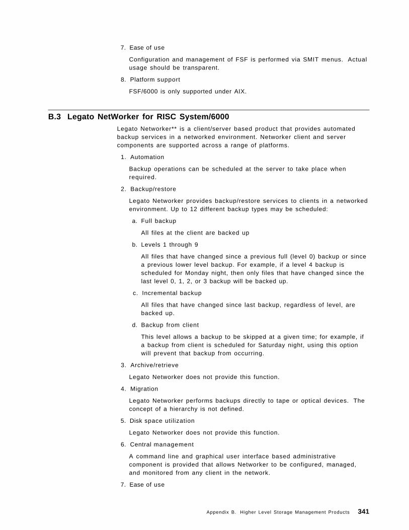
7. Ease of use
Configuration and management of FSF is performed via SMIT menus. Actualusage should be transparent.
8. Platform support
FSF/6000 is only supported under AIX.
B.3 Legato NetWorker for RISC System/6000Legato Networker** is a client/server based product that provides automatedbackup services in a networked environment. Networker client and servercomponents are supported across a range of platforms.
1. Automation
Backup operations can be scheduled at the server to take place whenrequired.
2. Backup/restore
Legato Networker provides backup/restore services to clients in a networkedenvironment. Up to 12 different backup types may be scheduled:
a. Full backup
All files at the client are backed up
b. Levels 1 through 9
All files that have changed since a previous full (level 0) backup or sincea previous lower level backup. For example, if a level 4 backup isscheduled for Monday night, then only files that have changed since thelast level 0, 1, 2, or 3 backup will be backed up.
c. Incremental backup
All files that have changed since last backup, regardless of level, arebacked up.
d. Backup from client
This level allows a backup to be skipped at a given time; for example, ifa backup from client is scheduled for Saturday night, using this optionwill prevent that backup from occurring.
3. Archive/retrieve
Legato Networker does not provide this function.
4. Migration
Legato Networker performs backups directly to tape or optical devices. Theconcept of a hierarchy is not defined.
5. Disk space utilization
Legato Networker does not provide this function.
6. Central management
A command line and graphical user interface based administrativecomponent is provided that allows Networker to be configured, managed,and monitored from any client in the network.
7. Ease of use
Appendix B. Higher Level Storage Management Products 341
Initial setup and configuration of Legato is manual, however once setup, thegraphical administrative component can be used to manage the product.There is no requirement for client interaction, so no interface is provided tothe client components; the code for clients is accessed via NFS, or locally ondisk, setup is manual.
8. Platform support
The server component is supported under AIX.
Client support is provided for AIX, Novell Netware, DOS, SunOS, Sony**NEW-OS, HP/UX, DEC ULTRIX, RISC/os, and SGI IRIX.
B.4 UniTree for RISC System/6000UniTree** is a client/server based hierarchical storage manager that providescentrally managed, automated hierarchical storage management in a networkedenvironment.
1. Automation
Similarly to FSF/6000, UniTree will automatically perform migration of clientdata within the UniTree file system down the defined hierarchy of storagedevices, based on configurable criteria. When data is requested by a client,UniTree can transparently retrieve the information from the lower level in thehierarchy, and make it available to the requesting client.
2. Backup/restore
UniTree does not provide backup/restore services for clients.
3. Archive/retrieve
As with FSF/6000, UniTree provides remote access to a managed file systemfor clients. The file system space is maintained through automatic archival offiles based upon configurable criteria (such as access frequency and size).When data is required by a client, it is transparently recovered from its placein the hierarchy.
4. Migration
UniTree defines a hierarchy of storage devices, similar to ADSM, with faster,more expensive media such as disk at the top, moving down to slower,larger capacity, cheaper media at the bottom. Information is migrated downthe hierarchy as described in the previous two sections thus ensuring thatthe most frequently accessed information is available on the fastest devices.
5. Disk space utilization
Disk space utilization is maximized at the server, as automatic archivalthrough migration ensures that there is always free space available. Thisdoes of course depend upon there being enough free space lower down thehierarchy for migration to succeed.
6. Central management
The storage hierarchy is administered at the server, though all configurationand management is via SMIT. Each client utilizes the services provided viaNFS (see 3.1.4.2, “Network File System” on page 62 for a brief description ofNFS), or FTP.
7. Ease of use
342 AIX Storage Management
Server management and administration is achieved via SMIT, and istherefore performed on the server machine. Client access to the UniTree filesystems is via NFS or FTP, and should be transparent to the user. Likewise,migration and archival/retrieval of information is performed automaticallyand should be transparent.
8. Platform support
The server is supported under AIX.
Client platforms supported with the AIX server include SUN, DEC, SGI, HPand AT&T**.
Appendix B. Higher Level Storage Management Products 343

344 AIX Storage Management
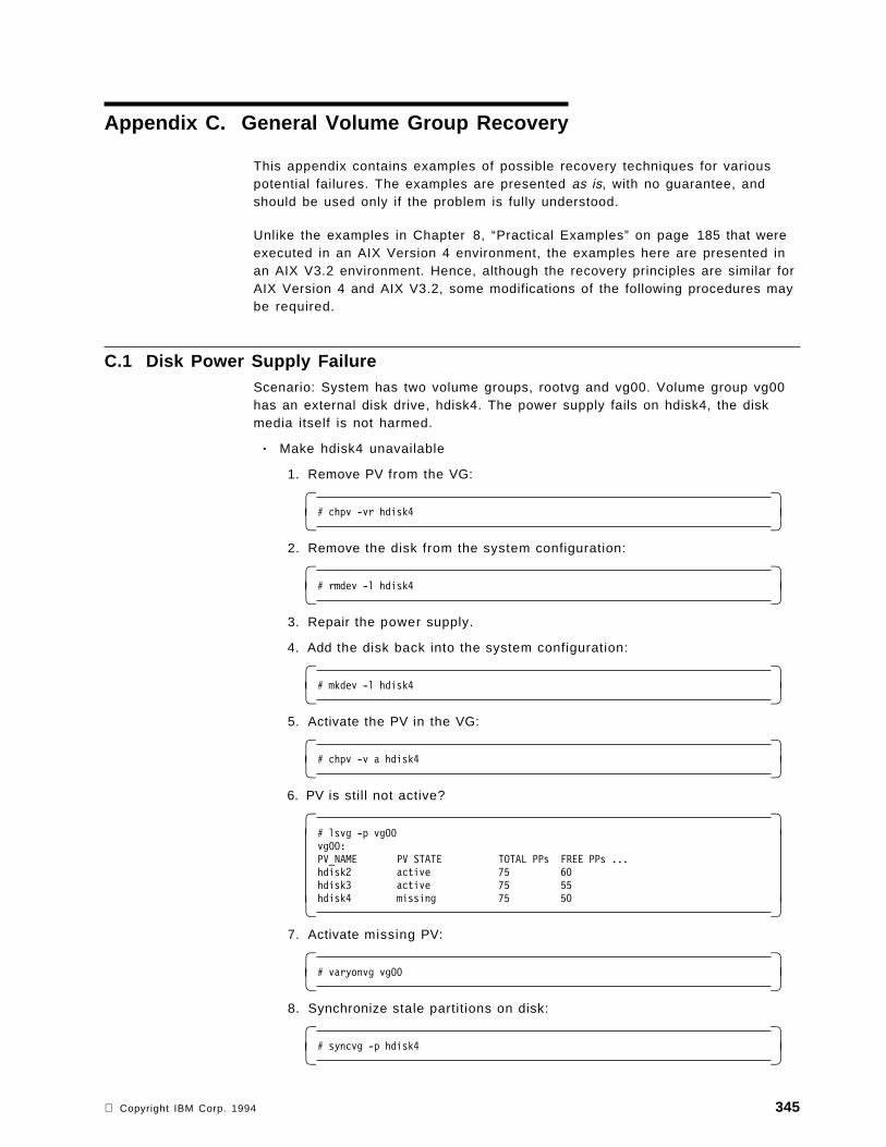
Appendix C. General Volume Group Recovery
This appendix contains examples of possible recovery techniques for variouspotential failures. The examples are presented as is, with no guarantee, andshould be used only if the problem is fully understood.
Unlike the examples in Chapter 8, “Practical Examples” on page 185 that wereexecuted in an AIX Version 4 environment, the examples here are presented inan AIX V3.2 environment. Hence, although the recovery principles are similar forAIX Version 4 and AIX V3.2, some modifications of the following procedures maybe required.
C.1 Disk Power Supply FailureScenario: System has two volume groups, rootvg and vg00. Volume group vg00has an external disk drive, hdisk4. The power supply fails on hdisk4, the diskmedia itself is not harmed.
• Make hdisk4 unavailable
1. Remove PV from the VG:
� �# chpv -vr hdisk4� �
2. Remove the disk from the system configuration:
� �# rmdev -l hdisk4� �
3. Repair the power supply.
4. Add the disk back into the system configuration:
� �# mkdev -l hdisk4� �
5. Activate the PV in the VG:
� �# chpv -v a hdisk4� �
6. PV is still not active?
� �# lsvg -p vg00vg00:PV_NAME PV STATE TOTAL PPs FREE PPs ...hdisk2 active 75 60hdisk3 active 75 55hdisk4 missing 75 50� �
7. Activate missing PV:
� �# varyonvg vg00� �
8. Synchronize stale partitions on disk:
� �# syncvg -p hdisk4� �
Copyright IBM Corp. 1994 345
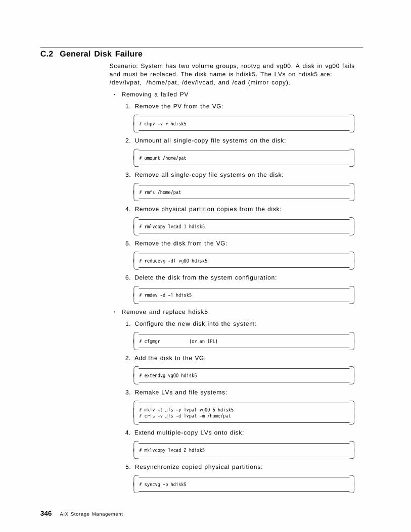
C.2 General Disk FailureScenario: System has two volume groups, rootvg and vg00. A disk in vg00 failsand must be replaced. The disk name is hdisk5. The LVs on hdisk5 are:/dev/lvpat, /home/pat, /dev/lvcad, and /cad (mirror copy).
• Removing a failed PV
1. Remove the PV from the VG:
� �# chpv -v r hdisk5� �
2. Unmount all single-copy file systems on the disk:
� �# umount /home/pat� �
3. Remove all single-copy file systems on the disk:
� �# rmfs /home/pat� �
4. Remove physical partit ion copies from the disk:
� �# rmlvcopy lvcad 1 hdisk5� �
5. Remove the disk from the VG:
� �# reducevg -df vg00 hdisk5� �
6. Delete the disk from the system configuration:
� �# rmdev -d -l hdisk5� �
• Remove and replace hdisk5
1. Configure the new disk into the system:
� �# cfgmgr (or an IPL)� �
2. Add the disk to the VG:
� �# extendvg vg00 hdisk5� �
3. Remake LVs and file systems:
� �# mklv -t jfs -y lvpat vg00 5 hdisk5# crfs -v jfs -d lvpat -m /home/pat� �
4. Extend multiple-copy LVs onto disk:
� �# mklvcopy lvcad 2 hdisk5� �
5. Resynchronize copied physical partitions:
� �# syncvg -p hdisk5� �
346 AIX Storage Management
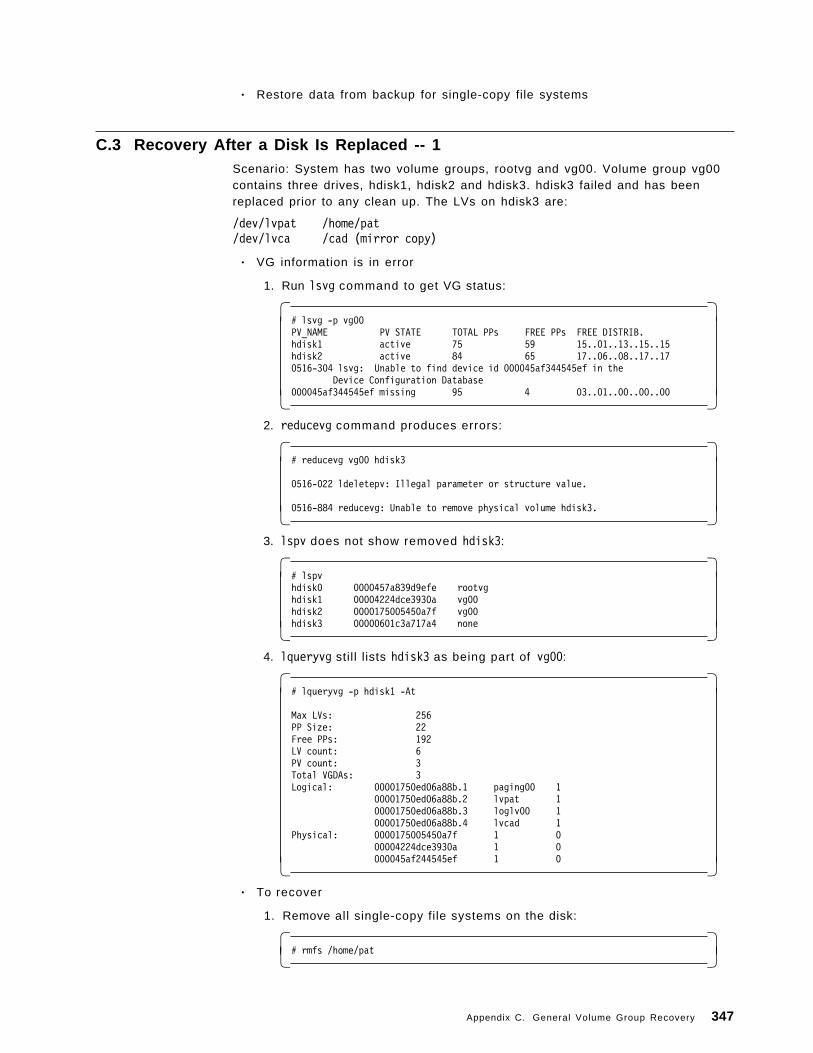
• Restore data from backup for single-copy file systems
C.3 Recovery After a Disk Is Replaced -- 1Scenario: System has two volume groups, rootvg and vg00. Volume group vg00contains three drives, hdisk1, hdisk2 and hdisk3. hdisk3 failed and has beenreplaced prior to any clean up. The LVs on hdisk3 are:
/dev/lvpat /home/pat/dev/lvca /cad (mirror copy)
• VG information is in error
1. Run lsvg command to get VG status:
� �# lsvg -p vg00PV_NAME PV STATE TOTAL PPs FREE PPs FREE DISTRIB.hdisk1 active 75 59 15..01..13..15..15hdisk2 active 84 65 17..06..08..17..170516-304 lsvg: Unable to find device id 000045af344545ef in the
Device Configuration Database000045af344545ef missing 95 4 03..01..00..00..00� �
2. reducevg command produces errors:
� �# reducevg vg00 hdisk3
0516-022 ldeletepv: Illegal parameter or structure value.
0516-884 reducevg: Unable to remove physical volume hdisk3.� � 3. lspv does not show removed hdisk3:
� �# lspvhdisk0 0000457a839d9efe rootvghdisk1 00004224dce3930a vg00hdisk2 0000175005450a7f vg00hdisk3 00000601c3a717a4 none� �
4. lqueryvg still l ists hdisk3 as being part of vg00:
� �# lqueryvg -p hdisk1 -At
Max LVs: 256PP Size: 22Free PPs: 192LV count: 6PV count: 3Total VGDAs: 3Logical: 00001750ed06a88b.1 paging00 1
00001750ed06a88b.2 lvpat 100001750ed06a88b.3 loglv00 100001750ed06a88b.4 lvcad 1
Physical: 0000175005450a7f 1 000004224dce3930a 1 0000045af244545ef 1 0� �
• To recover
1. Remove all single-copy file systems on the disk:
� �# rmfs /home/pat� �
Appendix C. General Volume Group Recovery 347
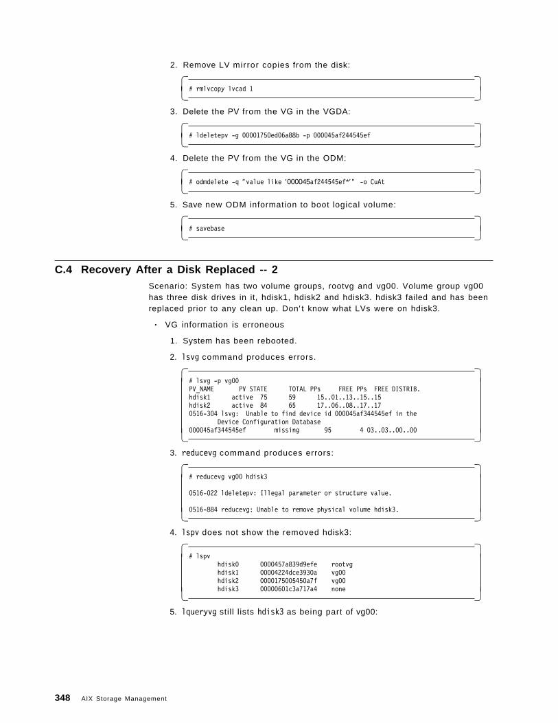
2. Remove LV mirror copies from the disk:
� �# rmlvcopy lvcad 1� �
3. Delete the PV from the VG in the VGDA:
� �# ldeletepv -g 00001750ed06a88b -p 000045af244545ef� �
4. Delete the PV from the VG in the ODM:
� �# odmdelete -q ″value like ′000045af244545ef*′ ″ -o CuAt� �
5. Save new ODM information to boot logical volume:
� �# savebase� �
C.4 Recovery After a Disk Replaced -- 2Scenario: System has two volume groups, rootvg and vg00. Volume group vg00has three disk drives in it, hdisk1, hdisk2 and hdisk3. hdisk3 failed and has beenreplaced prior to any clean up. Don′ t know what LVs were on hdisk3.
• VG information is erroneous
1. System has been rebooted.
2. lsvg command produces errors.
� �# lsvg -p vg00PV_NAME PV STATE TOTAL PPs FREE PPs FREE DISTRIB.hdisk1 active 75 59 15..01..13..15..15hdisk2 active 84 65 17..06..08..17..170516-304 lsvg: Unable to find device id 000045af344545ef in the
Device Configuration Database000045af344545ef missing 95 4 03..03..00..00� �
3. reducevg command produces errors:
� �# reducevg vg00 hdisk3
0516-022 ldeletepv: Illegal parameter or structure value.
0516-884 reducevg: Unable to remove physical volume hdisk3.� � 4. lspv does not show the removed hdisk3:
� �# lspv
hdisk0 0000457a839d9efe rootvghdisk1 00004224dce3930a vg00hdisk2 0000175005450a7f vg00hdisk3 00000601c3a717a4 none� �
5. lqueryvg still l ists hdisk3 as being part of vg00:
348 AIX Storage Management
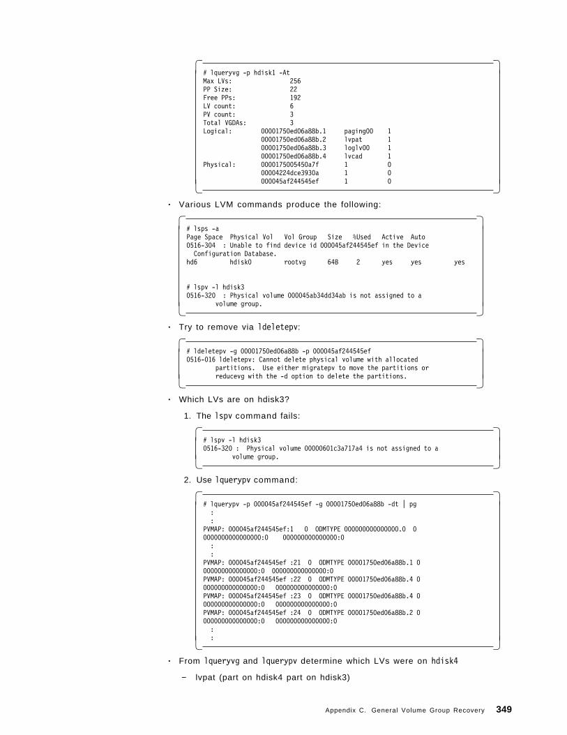
� �# lqueryvg -p hdisk1 -AtMax LVs: 256PP Size: 22Free PPs: 192LV count: 6PV count: 3Total VGDAs: 3Logical: 00001750ed06a88b.1 paging00 1
00001750ed06a88b.2 lvpat 100001750ed06a88b.3 loglv00 100001750ed06a88b.4 lvcad 1
Physical: 0000175005450a7f 1 000004224dce3930a 1 0000045af244545ef 1 0� �
• Various LVM commands produce the following:
� �# lsps -aPage Space Physical Vol Vol Group Size %Used Active Auto0516-304 : Unable to find device id 000045af244545ef in the DeviceConfiguration Database.
hd6 hdisk0 rootvg 64B 2 yes yes yes
# lspv -l hdisk30516-320 : Physical volume 000045ab34dd34ab is not assigned to a
volume group.� �• Try to remove via ldeletepv:
� �# ldeletepv -g 00001750ed06a88b -p 000045af244545ef0516-016 ldeletepv: Cannot delete physical volume with allocated
partitions. Use either migratepv to move the partitions orreducevg with the -d option to delete the partitions.� �
• Which LVs are on hdisk3?
1. The lspv command fails:
� �# lspv -l hdisk30516-320 : Physical volume 00000601c3a717a4 is not assigned to a
volume group.� � 2. Use lquerypv command:
� �# lquerypv -p 000045af244545ef -g 00001750ed06a88b -dt | pg::
PVMAP: 000045af244545ef:1 0 ODMTYPE 000000000000000.0 00000000000000000:0 000000000000000:0::
PVMAP: 000045af244545ef :21 0 ODMTYPE 00001750ed06a88b.1 0000000000000000:0 000000000000000:0PVMAP: 000045af244545ef :22 0 ODMTYPE 00001750ed06a88b.4 0000000000000000:0 000000000000000:0PVMAP: 000045af244545ef :23 0 ODMTYPE 00001750ed06a88b.4 0000000000000000:0 000000000000000:0PVMAP: 000045af244545ef :24 0 ODMTYPE 00001750ed06a88b.2 0000000000000000:0 000000000000000:0::� �
• From lqueryvg and lquerypv determine which LVs were on hdisk4
− lvpat (part on hdisk4 part on hdisk3)
Appendix C. General Volume Group Recovery 349
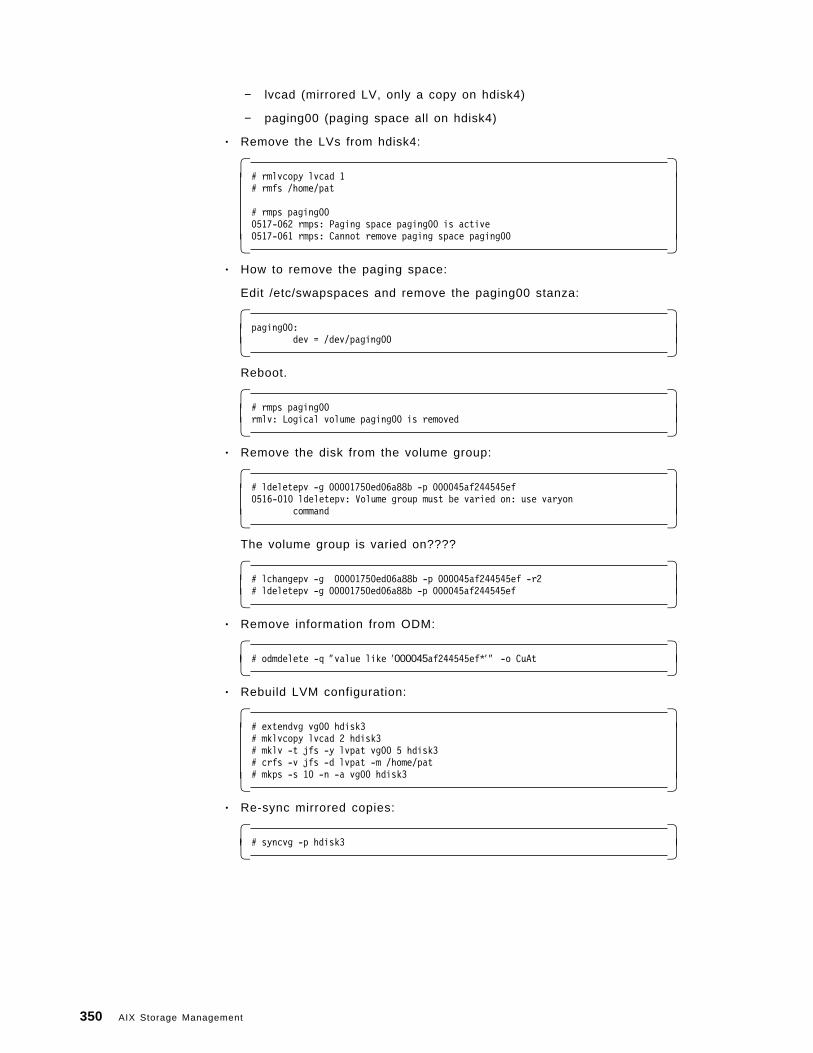
− lvcad (mirrored LV, only a copy on hdisk4)
− paging00 (paging space all on hdisk4)
• Remove the LVs from hdisk4:
� �# rmlvcopy lvcad 1# rmfs /home/pat
# rmps paging000517-062 rmps: Paging space paging00 is active0517-061 rmps: Cannot remove paging space paging00� �
• How to remove the paging space:
Edit /etc/swapspaces and remove the paging00 stanza:
� �paging00:
dev = /dev/paging00� �Reboot.
� �# rmps paging00rmlv: Logical volume paging00 is removed� �
• Remove the disk from the volume group:
� �# ldeletepv -g 00001750ed06a88b -p 000045af244545ef0516-010 ldeletepv: Volume group must be varied on: use varyon
command� �The volume group is varied on????
� �# lchangepv -g 00001750ed06a88b -p 000045af244545ef -r2# ldeletepv -g 00001750ed06a88b -p 000045af244545ef� �
• Remove information from ODM:
� �# odmdelete -q ″value like ′000045af244545ef*′ ″ -o CuAt� �
• Rebuild LVM configuration:
� �# extendvg vg00 hdisk3# mklvcopy lvcad 2 hdisk3# mklv -t jfs -y lvpat vg00 5 hdisk3# crfs -v jfs -d lvpat -m /home/pat# mkps -s 10 -n -a vg00 hdisk3� �
• Re-sync mirrored copies:
� �# syncvg -p hdisk3� �
350 AIX Storage Management
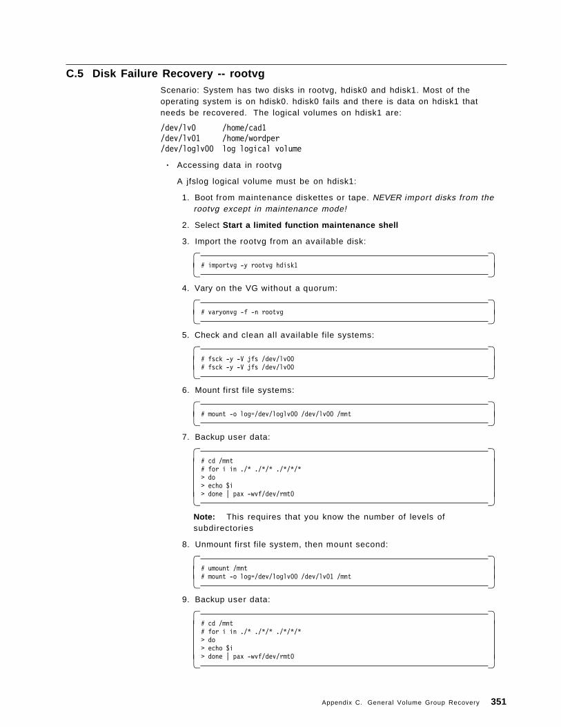
C.5 Disk Failure Recovery -- rootvgScenario: System has two disks in rootvg, hdisk0 and hdisk1. Most of theoperating system is on hdisk0. hdisk0 fails and there is data on hdisk1 thatneeds be recovered. The logical volumes on hdisk1 are:
/dev/lv0 /home/cad1/dev/lv01 /home/wordper/dev/loglv00 log logical volume
• Accessing data in rootvg
A jfslog logical volume must be on hdisk1:
1. Boot from maintenance diskettes or tape. NEVER import disks from therootvg except in maintenance mode!
2. Select Start a limited function maintenance shell
3. Import the rootvg from an available disk:
� �# importvg -y rootvg hdisk1� �
4. Vary on the VG without a quorum:
� �# varyonvg -f -n rootvg� �
5. Check and clean all available file systems:
� �# fsck -y -V jfs /dev/lv00# fsck -y -V jfs /dev/lv00� �
6. Mount first file systems:
� �# mount -o log=/dev/loglv00 /dev/lv00 /mnt� �
7. Backup user data:
� �# cd /mnt# for i in ./* ./*/* ./*/*/*> do> echo $i> done | pax -wvf/dev/rmt0� �
Note: This requires that you know the number of levels ofsubdirectories
8. Unmount first file system, then mount second:
� �# umount /mnt# mount -o log=/dev/loglv00 /dev/lv01 /mnt� �
9. Backup user data:
� �# cd /mnt# for i in ./* ./*/* ./*/*/*> do> echo $i> done | pax -wvf/dev/rmt0� �
Appendix C. General Volume Group Recovery 351
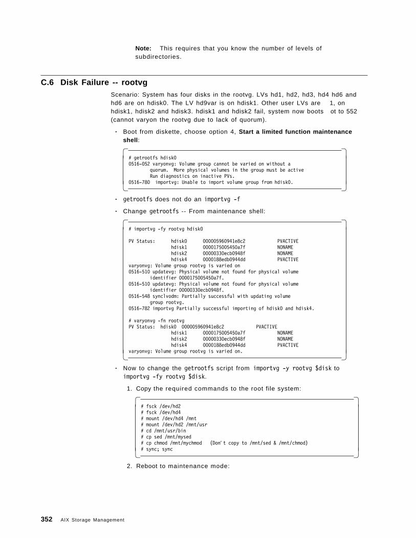
Note: This requires that you know the number of levels ofsubdirectories.
C.6 Disk Failure -- rootvgScenario: System has four disks in the rootvg. LVs hd1, hd2, hd3, hd4 hd6 andhd6 are on hdisk0. The LV hd9var is on hdisk1. Other user LVs are 1, onhdisk1, hdisk2 and hdisk3. hdisk1 and hdisk2 fail, system now boots ot to 552(cannot varyon the rootvg due to lack of quorum).
• Boot from diskette, choose option 4, Start a limited function maintenanceshell :
� �# getrootfs hdisk00516-052 varyonvg: Volume group cannot be varied on without a
quorum. More physical volumes in the group must be activeRun diagnostics on inactive PVs.
0516-780 importvg: Unable to import volume group from hdisk0.� �• getrootfs does not do an importvg -f
• Change getrootfs -- From maintenance shell:
� �# importvg -fy rootvg hdisk0
PV Status: hdisk0 000005960941e8c2 PVACTIVEhdisk1 0000175005450a7f NONAMEhdisk2 00000330ecb0948f NONAMEhdisk4 0000188edb0944dd PVACTIVE
varyonvg: Volume group rootvg is varied on0516-510 updatevg: Physical volume not found for physical volume
identifier 0000175005450a7f.0516-510 updatevg: Physical volume not found for physical volume
identifier 00000330ecb0948f.0516-548 synclvodm: Partially successful with updating volume
group rootvg.0516-782 importvg Partially successful importing of hdisk0 and hdisk4.
# varyonvg -fn rootvgPV Status: hdisk0 000005960941e8c2 PVACTIVE
hdisk1 0000175005450a7f NONAMEhdisk2 00000330ecb0948f NONAMEhdisk4 0000188edb0944dd PVACTIVE
varyonvg: Volume group rootvg is varied on.� �• Now to change the getrootfs script from importvg -y rootvg $disk to
importvg -fy rootvg $disk.
1. Copy the required commands to the root file system:
� �# fsck /dev/hd2# fsck /dev/hd4# mount /dev/hd4 /mnt# mount /dev/hd2 /mnt/usr# cd /mnt/usr/bin# cp sed /mnt/mysed# cp chmod /mnt/mychmod (Don′ t copy to /mnt/sed & /mnt/chmod)# sync; sync� �
2. Reboot to maintenance mode:
352 AIX Storage Management
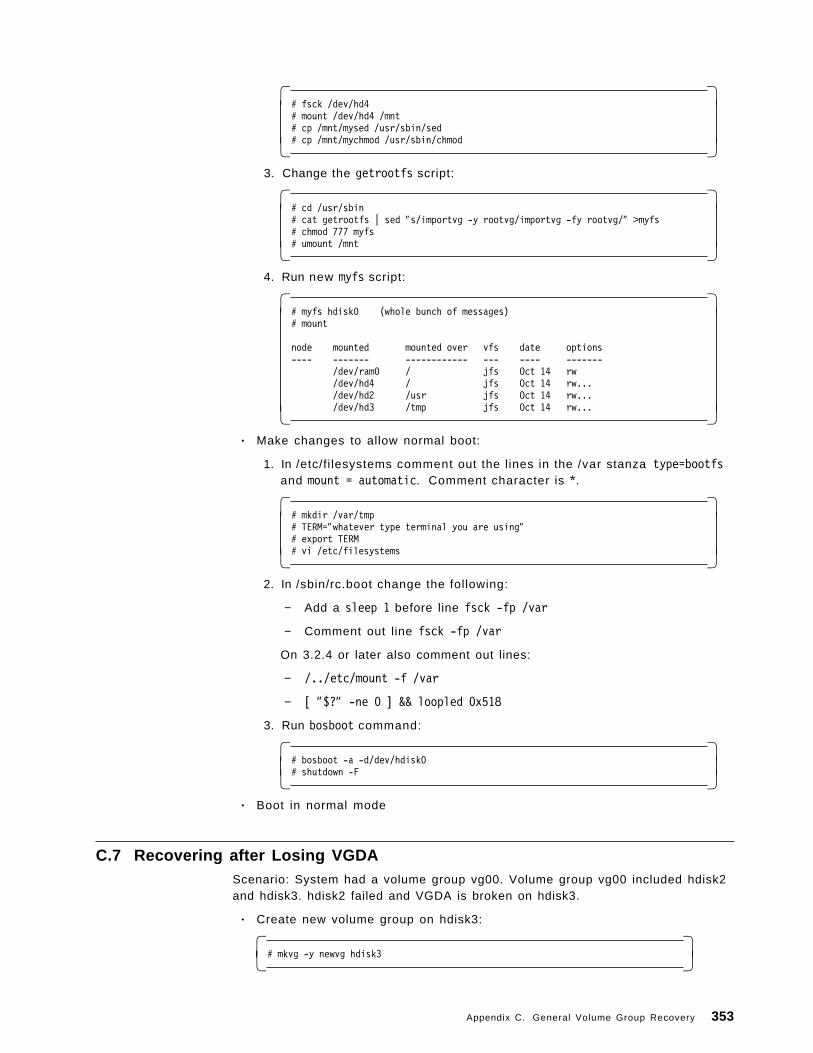
� �# fsck /dev/hd4# mount /dev/hd4 /mnt# cp /mnt/mysed /usr/sbin/sed# cp /mnt/mychmod /usr/sbin/chmod� �
3. Change the getrootfs script:
� �# cd /usr/sbin# cat getrootfs | sed ″s/importvg -y rootvg/importvg -fy rootvg/″ >myfs# chmod 777 myfs# umount /mnt� �
4. Run new myfs script:
� �# myfs hdisk0 (whole bunch of messages)# mount
node mounted mounted over vfs date options---- ------- ------------ --- ---- -------
/dev/ram0 / jfs Oct 14 rw/dev/hd4 / jfs Oct 14 rw.../dev/hd2 /usr jfs Oct 14 rw.../dev/hd3 /tmp jfs Oct 14 rw...� �
• Make changes to allow normal boot:
1. In /etc/fi lesystems comment out the lines in the /var stanza type=bootfsand mount = automatic. Comment character is *.
� �# mkdir /var/tmp# TERM=″whatever type terminal you are using″# export TERM# vi /etc/filesystems� �
2. In /sbin/rc.boot change the following:
− Add a sleep 1 before line fsck -fp /var
− Comment out line fsck -fp /var
On 3.2.4 or later also comment out lines:
− /../etc/mount -f /var
− [ ″$?″ -ne 0 ] && loopled 0x518
3. Run bosboot command:
� �# bosboot -a -d/dev/hdisk0# shutdown -F� �
• Boot in normal mode
C.7 Recovering after Losing VGDAScenario: System had a volume group vg00. Volume group vg00 included hdisk2and hdisk3. hdisk2 failed and VGDA is broken on hdisk3.
• Create new volume group on hdisk3:
� �# mkvg -y newvg hdisk3� �
Appendix C. General Volume Group Recovery 353
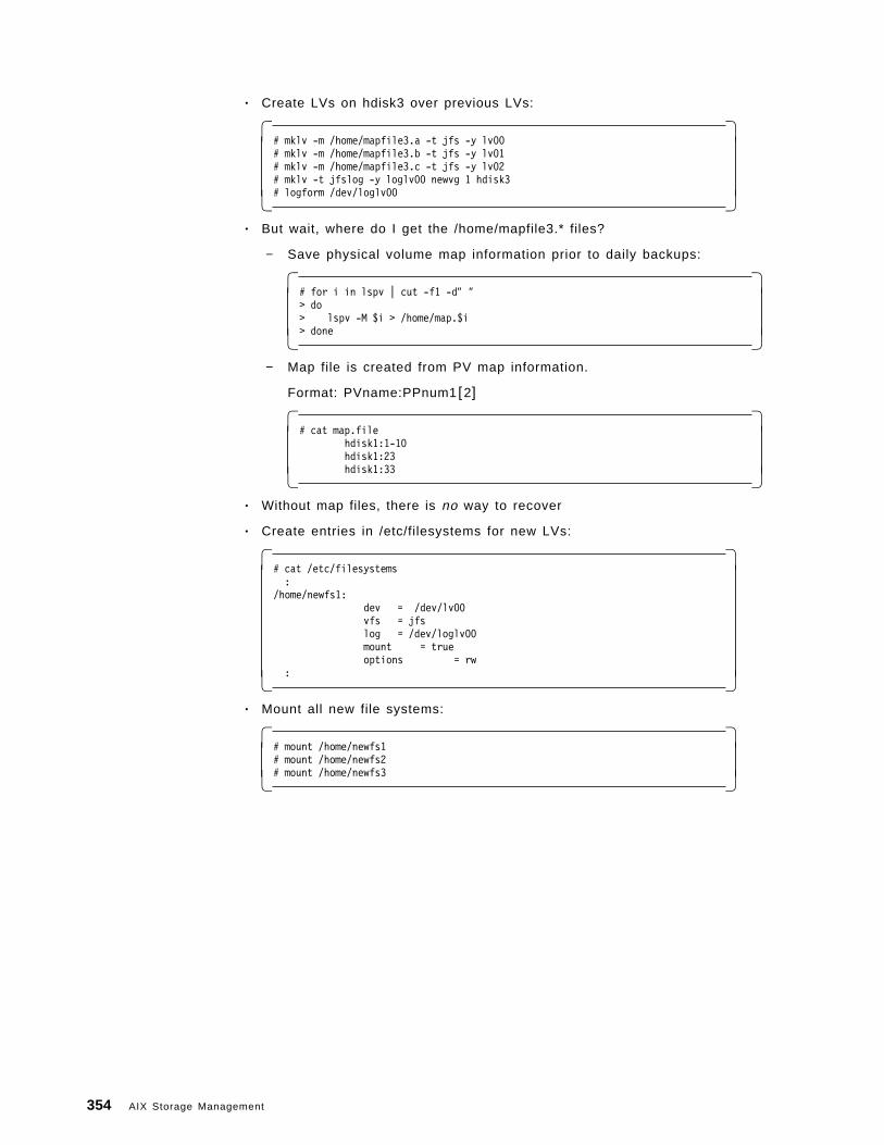
• Create LVs on hdisk3 over previous LVs:
� �# mklv -m /home/mapfile3.a -t jfs -y lv00# mklv -m /home/mapfile3.b -t jfs -y lv01# mklv -m /home/mapfile3.c -t jfs -y lv02# mklv -t jfslog -y loglv00 newvg 1 hdisk3# logform /dev/loglv00� �
• But wait, where do I get the /home/mapfile3.* files?
− Save physical volume map information prior to daily backups:
� �# for i in lspv | cut -f1 -d″ ″> do> lspv -M $i > /home/map.$i> done� �
− Map file is created from PV map information.
Format: PVname:PPnum1 [2]
� �# cat map.file
hdisk1:1-10hdisk1:23hdisk1:33� �
• Without map files, there is no way to recover
• Create entries in /etc/filesystems for new LVs:
� �# cat /etc/filesystems:
/home/newfs1:dev = /dev/lv00vfs = jfslog = /dev/loglv00mount = trueoptions = rw
:� �• Mount all new file systems:
� �# mount /home/newfs1# mount /home/newfs2# mount /home/newfs3� �
354 AIX Storage Management
Glossary
Ablative . Ablative technology util izes heat to removea layer of some material. In this context, it relates towriting information with a laser by using the lasersheat to burn away a layer of the recording medium,thereby representing a binary value.
Access pattern skew . This refers to the tendency forreference to information to follow a pattern whereby,information is referenced from a certain area forsome time, then another area, then a further one,rather than completely random jumps. Thus, ifinformation in a file was written sequentially across anumber of disks, utilization would tend towards onedisk at a time. If however, the file data is split intoblocks, and each block written to a separate disk, theskew is eliminated.
Access time . This refers to the total length of timefrom the initiation of a request for data, to the start ofthe receipt of that data from a device.
Actuators . An actuator is the mechanical assemblythat is responsible for moving the disk head back andforth across the disk surface.
Allocation group . An allocation group consists of aset of i-node pointers to data blocks, and the datablocks themselves. This is a file system entity used toimprove access to files within a file system based onlocality of reference.
Areal density . This defines the density at whichindividual bits can resolved by the read head. Thisequates to the maximum bit density supported by themedia.
Archive . Archiving involves moving data from thelocation that it is usually accessed from (normallyfast, expensive storage), to lower cost storage suchas tape. Information is normally archived if access toit will be very infrequent. Contrast with retrieval.
Asynchronous . This refers to an operation that canoccur independently of other operations. Anasynchronous communication for example, can besent and then other work initiated without waiting fora response. Contrast with synchronous.
Autochanger . An autochanger is a mechanical devicedesigned to load an remove media from a driveautomatically. Tape and optical l ibraries haveautochangers.
Backup . Backup involves taking a copy of data,usually on some form of removable media, so that inthe event that information is lost, it can be easilyrecovered. Contrast with restore.
Bad block relocation . When a write of a block of datato a disk occurs, some software (and in some casesthe hardware), is capable of detecting that the writefailed (usually with a read following the write to test).In this case, transparently to the process thatrequested the write, the hardware or software canmark the block as bad so that it will not be usedagain, and redirect the write to a fresh block.
Banding . Traditionally, writing of bits to a disksurface occurs in a regular fashion; thus the further intoward the center of the disk, the less information canbe stored. Banding refers to a process of dividing thedisk surface into a number of concentric regions. Asthe disk write head moves into regions closer to thecenter of the disk, the bit write frequency increasesproportionally, thereby maintaining the bit density.
Block . A block is a unit of data to be written or read.There are various block sizes, depending upon themedia and software. Disk device drivers currently usea block size of 512 bytes to write to the disk.
Bus . A bus is a data and control path betweendevices. It consists of power lines, a number of datalines, and a number of control lines. There arevarious standards including Micro Channel and PCI.
Cache . A cache is a area of extremely fast (usuallyexpensive) memory that is used to maintainfrequently accessed information, or store informationtemporarily. Caches are used in various parts of acomputer system. In disk subsystem controllers forexample, writes to disk will actually occur to thecache so that a completion return code can be quicklyreturned to the writing process. The actual write willoccur from the cache when the subsystem has time tosatisfy it. The CPU also maintains several cacheswhere instructions and data can be pre-loaded whilethe current instruction is executing.
Caddy . A caddy is a removable casing that aCD-ROM is placed in before being loaded into theoptical drive.
CCW. Continuous composite write describes themagneto-optical implementation of WORM. Erasureand rewriting are prevented by simply not allowingthe functions to take place. Contrast with WORM.
CD-ROM. A CD-ROM is an optical disk that hasinformation stored on it before it is distributed. Theinformation is permanently stored and cannot beerased or rewritten.
Command tag queueing . Command tag queuingrefers to the SCSI-2 implementation of piggy-backingcommands together to a device on the SCSI bus.
Copyright IBM Corp. 1994 355
This effectively allows commands to be overlapped,thereby improving performance.
Compression . Compression techniques utilizehardware or software implemented algorithms thatare able to reduce the amount of storage needed bydata. The reduction in space is dependent upon thedata used, as well as the compression algorithm.Contrast with decompression.
Data transfer rate . This is the rate at which data canbe moved from the host system to a device. It isnormally measured in KB/sec or MB/sec.
Decompression . This is the process of restoringcompressed data to its original state, so that it can beused again. Contrast with compression.
Device driver . A device driver is a piece of softwarewritten to assist in the management of a specificdevice. Other software will use the device driver asthe interface to the device for reading, writing andcontrol functions.
Differential . This refers to the communicationstechnique of transmitting information as the differencevoltage between two signals. Normally, information istransmitted as a single signal and can be corruptedby noise from external sources. Differentialtransmission means that both signal lines will beequally affected by any noise, the difference betweenthem, the actual information, remaining constant.
Directory . A directory is a file system entity that isused to organize related information within fi lesystems. The space allocated to a file system for filestorage can be subdivided into directories so thatfiles can be more sensibly organized. Directories canhave sub-directories, thereby forming anorganizational hierarchy. Files themselves can bethought of as being located within a specific directory,and access to them is defined by a path that is thedirectory hierarchy leading to them.
Diskette . A diskette contains a circular piece ofmagnetic material that is read and written in thesame way as fixed magnetic disk. Diskettes aredesigned to be removed and easily transported and toenable this function, have lower tolerances and henceless storage capacity than fixed disks.
Disk pack . A disk pack contains a traditional fixeddisk but can be removed in its entirety from thesupport structure (power, cooling, and connectionbus). It is far less portable than a diskette, but cancontain as much information as a normal fixed disk.
Dispatch . This refers to the action of taking aprocess that is waiting to use the processor from itswait queue and loading it into the processor forexecution.
Dump . Should an unrecoverable error occur withinthe computer system, a dump usually occurs beforethe system halts completely, if possible. The dumpconsists of the contents of main memory andprocessor registers immediately prior to the error.
Elevator seeking . In order to maximize the efficiencyof disk head seeks, a simple sort of the request queuecan be implemented in software or hardware. Thiswill allow the disk head to satisfy requests using thesmallest possible head movements moving into thecenter of the disk and then out again, therebyminimizing seek times.
Fast and wide . The SCSI-2 standard defines a databus up to 32 bits wide, and with a 10MHz cycle time.This is currently utilized at 2 bytes giving a data rateof 20MB/sec. Fast refers to the clock speed, and wideto the data bus.
Fault tolerance . Systems that have total redundancyare called fault tolerant. This means that all operationcritical systems have a hot standby that can take overin the event of failure of the primary component.
File system . A file system is a high level entity thatmanages the storage of data. Through the file system,information can be organized within directories andfiles created, read, written, and erased.
Floppy disk . This is an earlier term for a diskette. Itoriginates from the fact that older diskette designsutilized soft covers that were pliable.
Fragment . A fragment is a subdivision of a filesystem block. Blocks can be divided into a number offragments (up to eight, dependent upon file systemcreation parameters). The purpose of fragments is tominimize the disk space wastage that occurs as aresult of partially allocated blocks.
Frame . Real memory in a computer system isdivided into sections for ease of manipulation. Thesesections vary in size depending upon the systemimplementation, and are known as page frames.Under AIX, a page frame is 4KB in size.
HDA . The mechanical component composed of thedisk head, actuator, motor and platters, is known asthe head disk assembly.
Helical scan . This technology was introduced fromthe consumer video marketplace. Tape is partiallywrapped around a spinning recording head that ismounted at an angle to the tapes direction of travel.This results in data tracks being recorded at an angleacross the tapes surface, thereby using the taperecording area most efficiently, and maximizingcapacity.
Hierarchical . This refers to an organizational methodthat involves levels that are accessed by moving fromone to another starting at the top of the hierarchy. An
356 AIX Storage Management
example is a directory tree in a file system, wherefiles are found by navigating from the top of the treethrough a series of subdirectories, until the file isfound.
Hierarchical storage management . At a higher level,treating the various storage technologies available aslevels, with disk being the level for interactive access,through optical for intermediate, to tape forbackup/archive, defines a storage hierarchy throughwhich data can be migrated according to space andusage requirements. The process of managing thismechanism is known as hierarchical storagemanagement.
IDRC. This is a compression technique implementedon some IBM tape drives that allows data beingwritten to the tape to be compressed as the writing isbeing done, thereby increasing the capacity of thetape medium. When data is read back, it isdecompressed as the read occurs.
I-node . An i-node is a file system entity that is usedto locate a files data on the actual disk. It containspointers to the physical disk blocks containing thedata.
JFS log . Every action that occurs within a file systemis recorded into a log known as the journaled filesystem log. These actions include events such asopening files, writes to files, and closing files. If thesystem should fail during operation, upon reboot, thefile systems can be brought back to consistent statesby replaying the information contained in the log.
Journaled file system . The Journaled File System isthe main AIX file system implementation. It defines afile system with a JFS log.
Library . A tape or optical drive coupled with anautochanger and racks of media comprises a library.Media can be unloaded and loaded from the racksautomatically, on request from the host system.
Licensed program products . All software productspurchased for use on the RS/6000 are known aslicensed program products.
Linear . Linear with regard to tape technology impliesrecording information in a straight horizontal directionalong the length of the tape.
Locality of reference . If when a process is executing,most of the time it runs is spent in several smallsections of the code, with occasional jumps to otherparts, then the process is said to display good localityof reference. This is beneficial, as it means that theoperating system can maintain the small number ofmost utilized sections of the process in memory, andthereby achieve good performance.
Logical partition . A logical volume is composed of anumber of logical partitions. Each logical partition
maps directly to from one to three physical partitionswhere data is actually stored.
Logical volume . A logical volume is an area ofphysical disk storage comprising a number of logicalpartitions. Logical volume can be written to directly,or a file system can be created within them.
Logical volume device driver . The logical volumemanager device driver is one of the components ofthe logical volume manager. It implements the logicalvolume manager policies for logical volumes.
Logical volume manager . The logical volumemanager is a collection of device drivers, disk dataareas, daemons, and management subroutines thatcollectively form a high level interface to disk storage.It provides functions for the creation, manipulation,access, and deletion of logical volumes.
Longitudinal . In terms of tape technology,longitudinal recording defines a mechanism for datarecording that involves writing linear tracks on thetape surface.
Magneto-resistive . This technology is used toimplement rewritable optical disk storage. Magneticmaterial in the optical media surface is heated with alaser and then its polarity altered with anelectromagnet. The material used is such that a lowpowered laser shined on the material is polarized indifferent directions depending upon the magneticpolarity, thereby representing binary states.
Mirroring . This refers to the practice of maintainingtwo or more concurrent copies of information. Allcopies are updated for each write of the information.In the event of loss of a copy, the data can still beaccessed from another copy.
Mirror write consistency . When mirroring isimplemented and data is being written, there is adanger that if the system should fail during the writingof the data, all copies may end up in an inconsistentstate. Mirror write consistency util izes cache storageto maintain the data to be written until all copies havebeen updated, thereby ensuring consistency betweencopies.
MTBF . Mean time between failure is a measurementof the reliability of hardware components. It iscalculated as total operating time of a group ofcomponents making up a device divided by thenumber of components in the device that fail overthat period.
Multitasking . This is the capability of a computersystem to divide its time between multiple processesor tasks, such that the processes all appear to beexecuting concurrently.
NFS. The network file system is an implementationof a remote file system. Files stored on a remote
Glossary 357
machine are made to appear as if they were beingaccessed from the local machine.
NIC. Numerically intensive computing generallyrefers to applications that require much intensivecalculation, such as modelling or statistical analysis.
Non-volatile . This typically refers to memory storagethat is capable of retaining information during periodswithout power.
OEMI. This is a standard third party interface used toattach peripheral devices.
OLTP . This describes a category of application thatperforms repetitive processing of records, such asbank account processing.
Optical disk . A storage medium that is read usingoptical technology, usually a laser. There are anumber of different writing mechanisms includingablative, magneto-optical, and phase change.
Page . Generally, a page describes a block ofinformation. In AIX a page is 4KB.
Page fault . When a page of an application that waswaiting on some event, and has been paged out, isrequired, the CPU will try and access it, and in sodoing generate a page fault as the page will not be inmemory. The fault causes the missing page to belocated in page space and copied back into memory,probably causing some other currently inactive pageto be swapped out.
Page frame . Main memory is divided into a numberof pages frames, in AIX, these are 4KB in size. Pagesof information are then loaded into page frames.
Page space . Main memory is finite,and soonbecomes filled with the pages of many executingapplications. If at this point, more applications wish torun, there would be no room and they would have towait. Page space defines a pool of storage on diskwhere pages of applications that are waiting on someevent can be temporarily stored to make room forother application pages.
Paging . Paging describes the process of temporarilycopying pages from main memory to page space inorder to free up memory page frames for otherapplications to use.
Parallel write . When mirroring is being used, parallelwrite means that data to be written will besimultaneously scheduled to all copies. This is thequickest way to implement mirroring, though a failureduring write will result in no valid copies. Contrastwith sequential write.
Physical partition . A physical volume is divided upinto a number of physical partitions whose size isdefined when the volume group containing the disk is
created. These partitions are then mapped to logicalpartitions when a logical volume is created.
Physical volume . Before a physical disk can beadded to a volume group, it must be defined as aphysical volume. This process assigns the disk aunique number by which it will be identified, andcreates some on-disk data areas which are used tostore information regarding the disks usage.
Physical volume identifier . The unique numberassigned to a physical volume is known as thephysical volume identifier.
Pipeline . Pipelining refers to the process ofpre-fetching instructions into an instruction cache inorder to speed up process execution.
Platter . Inside a disk drive is a spindle that connectsa number of disks coated with a magnetic material.Read/write heads on arms are moved back and forthradially over the disks, which are spun to allow aseries of concentric tracks to be written on each disksurface. Each such disk is known as a platter.
PPM. This refers to the process of determining asignal value by its presence or absence. Thus if thesignal is there, it represents logic one, if not, logiczero. With optical disk, a low powered laser utilizesthe same mechanism to read data, a returned signalbeing logic one, no returned signal logic zero.
PWM. This refers to the process of establishing asignal value using the change in state from present toabsent. Thus a transition from absent to present islogic one, a transition from present to absent is logiczero. Using this technique means that data can bemore densely packed as discrete signals are nolonger required. Optical technology uses thistechnique where dots on the disk can actually beoverlapped as it is only the change in state from asequence of returned signals to no signal (or viceversa) that indicates a binary value.
Quorum . The logical volume manager implements aprocess known as quorum checking. This is used toensure that before a volume group can be madeavailable for use, over 50% of the disks in the grouphave valid VGDAs, indicating that they containuncorrupted data. The quorum is the number of disksrequired to constitute more than 50% of the totaldisks in the group.
RAID . RAID arrays are designed to increaseperformance or availabil ity through theimplementation of one of the following modes ofoperation. RAID 0 stripes data across the disks formaximum performance. RAID 1 pairs off the disks andmirrors data on each disk. RAID 3 stripes data acrossthe disks and uses one further disk to record parityinformation to allow data to be reconstructed in theevent of loss of one disk. RAID 5 splits the data into
358 AIX Storage Management
blocks and writes blocks sequentially across the disks,intermixing parity blocks with data blocks.
Read ahead . When an application wishes to access adata file, just the first few pages of data are actuallyread into memory. As the file is used, more pages areread in according to two system parameters,minpgahead, and maxpgahead. If the operatingsystem detects that the file is being accessedsequentially, then it will read in minpgahead morepages when further pages are required. If access isstill sequential, the next time pages are required,minpgahead + 2 will be read in. This value isincremented by two as long as the access remainssequential up to maxpgahead thereby enhancingperformance for sequential reads.
Redundancy . Providing a duplicate component withina subsystem that can be switched in and used in theevent of failure of the primary component means thatthe component has redundancy.
Restore . Restoring is the process of copyinginformation back from its safe location (usually someform of removable media) to replace the original copythat has somehow been lost. Contrast with backup.
Retrieve . Retrieval is the process of moving databack from archive storage to its original locationwhere it can be accessed. Contrast with archive.
Rotational Latency . When a block of data is to beread/written from a disk, the actuator moves theread/write head to the track where the block islocated and then waits for the platter to rotate thestart of the block underneath so reading/writing canbegin. This delay before the start of the block arrivesis called rotational latency.
Scheduler . The operating system maintains severalpriority queues of processes waiting for their turn toexecute on the processor. The scheduler is theoperating system component that decides whichprocess is eligible to run next, and selects it fordispatch.
SCSI. The SCSI standards define a communicationsprotocol and physical interfaces to support theattachment of SCSI compatible devices to a hostsystem, and thence the devices controlled, andinformation read and written.
Seek time . The seek time is the sum of the timetaken for the disk head to be moved to the requiredtrack plus the rotational latency.
Segment . The total AIX address space of 4 petabytesis divided into segments of 256MB. There are severaldifferent types of segment including working,persistent, client, and log segments.
Sequential write . When mirroring is being used,sequential write means that data to be written is
scheduled to each mirror copy in turn, with the nextnot occurring until the previous has completed. Thismethod gives the highest chances of at least onecopy surviving in the event of failure during the write,but at the cost of performance. Contrast with parallelwrite.
Serial . When data is sent a single bit at a time(usually over two wires), the communications is saidto be serial.
Serpentine track interleaving . This technology is anenhancement to longitudinal recording where the datais written to tape in a series of blocks. The tape headis capable of writing/reading several trackssimultaneously which it does during one pass downthe length of the tape. The head is then steppedlaterally and the pass restarted in the oppositedirection. The stepping continues until the tape widthis full.
Single ended . Single ended technology refers tonon-differential communications where information istransmitted serially using four wires, two to send andtwo to receive.
SSA . This defines a new communications protocoland physical interfaces for connecting peripherals tothe host system and communicating with them.
Stale . When mirroring is being used, should one ofthe copies of the data fail, then the copy is marked asstale, which reflects the fact that it can no longer beconsidered accurate until it has been resynchronizedwith the other copies after repairs have beeneffected.
Streaming . When data is written continuously to adevice in one long run, the data is said to bestreamed to the device, and the device itself capableof streaming.
Striping . Splitting data to be written into equal sizedblocks and writing blocks simultaneously to separatedisk drives is called striping the data and maximizesperformance to the disks. Reading the data back isalso scheduled in parallel, with a block being readconcurrently from each disk then reassembled at thehost.
Stripe width . The size of the block that data is splitinto for striping is known as the stripe width.
Subsystem . A subsystem is a collection ofcomponents that together perform some function onbehalf of the host system. An example is a RAIDarray subsystem.
Superblock . A file system is split into a number ofblocks whose size is 4KB in AIX. The second andthirty first (a backup copy) are designated as thesuperblock and contain administrative information
Glossary 359
regarding the file system such as fragment size andoverall fi le system size.
Swapping . This is an alternative name for paging.
Swap space . This is an alternative name for pagespace.
Synchronous . This defines an operation that mustoccur with a fixed time relationship to anotheroperation. An example of this is synchronouscommunications where each end maintains a clock,and data is sent at regular intervals, each clock tickfor example. Contrast with asynchronous.
TCP/IP. This is a set of communications protocolsthat support the transmission of information betweencomputers.
Thin film . This technology is used in the constructionof read heads for tape and disk devices. It allows avery high degree of sensitivity and a correspondinglyhigh bit density on the recording medium.
Throughput . This defines the rate at whichinformation can be transferred across an interfaceand is a measure of performance. It is usuallymeasured in KB/sec or MB/sec.
Track . This defines a single one bit wide stream ofphysical data written on a storage medium. Tracksare concentric circles on disk and most optical media,horizontal lines on longitudinal technology tape, andinclined lines on helical scan technology tape.
Volatile . Memory that does not maintain its contentsduring periods of no power is known as volatilestorage. Contrast with non-volatile.
Volume group . This is a logical volume managerentity that contains a number of physical volumes.
Volume group descriptor area . Each physical volumehas at least one VGDA stored on it. The VGDAcontains information regarding the organization andlocation of all logical volumes and physical volumeswithin the volume group.
Volume group identifier . Each volume group has aunique number identifying it known as the volumegroup identifier.
Volume group status area . Each physical volume hasat least one VGSA stored on it. The VGSA containsinformation regarding the status of all logical volumesand physical volumes within the volume group.
Virtual memory manager . This operating systemcomponent is responsible for managing memoryallocation and usage. The VMM manages themappings between real memory, page space and thefile systems, and all addressing requests go throughit.
WORM. Optical media that util izes a destructivewriting process meaning that once written,information cannot be erased. Contrast with CCW.
360 AIX Storage Management
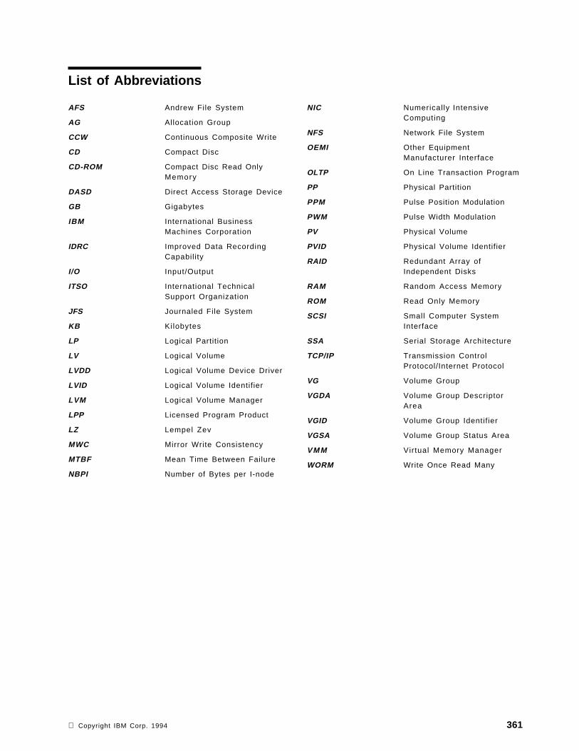
List of Abbreviations
AFS Andrew File System
AG Allocation Group
CCW Continuous Composite Write
CD Compact Disc
CD-ROM Compact Disc Read OnlyMemory
DASD Direct Access Storage Device
GB Gigabytes
IBM International BusinessMachines Corporation
IDRC Improved Data RecordingCapability
I/O Input/Output
ITSO International TechnicalSupport Organization
JFS Journaled File System
KB Kilobytes
LP Logical Partition
LV Logical Volume
LVDD Logical Volume Device Driver
LVID Logical Volume Identifier
LVM Logical Volume Manager
LPP Licensed Program Product
LZ Lempel Zev
MWC Mirror Write Consistency
MTBF Mean Time Between Failure
NBPI Number of Bytes per I-node
NIC Numerically IntensiveComputing
NFS Network File System
OEMI Other EquipmentManufacturer Interface
OLTP On Line Transaction Program
PP Physical Partition
PPM Pulse Position Modulation
PWM Pulse Width Modulation
PV Physical Volume
PVID Physical Volume Identifier
RAID Redundant Array ofIndependent Disks
RAM Random Access Memory
ROM Read Only Memory
SCSI Small Computer SystemInterface
SSA Serial Storage Architecture
TCP/IP Transmission ControlProtocol/Internet Protocol
VG Volume Group
VGDA Volume Group DescriptorArea
VGID Volume Group Identifier
VGSA Volume Group Status Area
VMM Virtual Memory Manager
WORM Write Once Read Many
Copyright IBM Corp. 1994 361

362 AIX Storage Management
Index
Aabbreviations 361Ablat ive 41Access density 17Access frequency 17Access t ime 43Access type 17acronyms 361ACTIVE PVs 111active/complete 110, 117active/part ial 110, 117Actuator 25Adapters
adapters available 321addressabil i ty 22availabil i ty design 86cabling requirements 22cost 23device support 22High Performance Disk Drive Subsystem 24High Performance Parallel Interface 24other adapters 25performance 22performance design 82reliabil i ty 22System/370 Channel Emulator 25
Address space 48Administrat ion overview 14ADSM 65, 338AFS 63ALLOCATABLE 101Allocate each logical partition copy on a SEPARATE
physical volume 121, 125Allocation groups 60API provision 338Applications
availabil ity design 88components 47data access 7performance design 85
Archival l i fe 40, 42Archive 337, 339, 342Areal density 26Asynchronous 23Asynchronous disk I/O 85, 88AUTO ON 112Autochanger 9Automatic management 12automation 337, 338, 340, 341, 342Availabi l i ty
device selection 18disk devices 33optical 10overview 10
Availabi l i ty (continued)tape 10tape devices 38
Avai labi l i ty Managementavailabil ity design example 208creating LVs for availability 123design 86managing 123modifying LVs for availability 125reorganizing VGs for availability 126
Available 96, 97, 103
BBackup 128, 129, 157
archive commands 155backup design example 244backup media 91backup methods 91complete system backup 90concepts 2, 6design 90higher level tools 337, 339, 341incremental backup 89, 90longevity 18making scheduled backups 132managing 127overview 64, 89recycling backups 89scheduled 7system image and user VGs 130user files and file systems 127using mksysb example 256V4 archive commands 164
Backup by file system 91Backup by name 91Backup by volume group 91Bad block relocation 54, 56Banding 27BB POLICY 118
CC 98Cache 32, 65Capacity
constraints 29device selection 18disk devices 27diskette 3optical devices 43overview 11tape devices 38
CCW 41
Copyright IBM Corp. 1994 363
CD-ROM file system 63Central management 337, 339, 340, 341, 342cfgmgr 95, 96chlv
changing LV policies 126command syntax 142modifying LVs for performance 122
chpvcommand syntax 142making PVs available 97making PVs unavailable 97restricting PP allocation 96
chvgcommand syntax 142disable quorum checking 105enable quorum checking 105prevent VG autovaryon 104unlocking a VG 105V4 command syntax 160varyon VG automatically 104
close/syncd 112closed 118Compatibi l i ty 92Compression
JFS compression algorithm 73JFS compression example 279JFS compression implementation 73JFS compression performance 73JFS compression technology 72JFS V4 overview 61performance design 84space design 81tape 9
Compression algorithm 122Concepts
design 79general 1hardwaresoftware 6
Configuration 14COPIES 118, 119Cost per megabyte 17cplv 116, 142crfs 121, 127, 151
DData age 18Data archive 7, 12Data rate 17Decompression 9Defined 96, 97defragfs 70, 162DESCRIPTION 98, 99Device attributes 21Device driver 6Device queue limits 85df 181, 182
Directories 58Disk Devices
availabi l i ty 33capacity 27concepts 4disk devices available 326fault tolerance 33performance 30performance design 82selecting disks 27technology 25
Disk failure 13Disk I/O pacing 85Disk packs 4Diskettes 3, 14DISTRIBUTION 119du 181, 182dump space 76Dye-polymer 41
EEACH LP COPY ON A SEPARATE PV 118Ease of use 338, 339, 341, 342Elevator seeking 26Enable WRITE VERIFY 121, 125Error Class 99ERROR LABEL 99Error Type 99errpt 98Executable 47exportvg 106, 142extendlv 116, 143extendvg 105, 143
FFailure Causes: 99File containing ALLOCATION MAP 121, 125File name archive 91File system size design 82File Systems
accessing file systems 63administration commands 151availabil ity design 88concepts 6creating a compressed JFS example 280creating a JFS greater than 2GB example 288creating for performance 120JFS fragment size example 273JFS V4 size 62, 77JFS version 4 enhancements 61journaled fi le system 59Network File System 62organization 58other fi le systems 63overview 58performance design 83space design 81
364 AIX Storage Management
f i leplace 183Fragment allocation 69, 71Fragment size 69Fragment Size (bytes) 122Fragmentation 70, 72Fragments
fragment allocation map 72fragments example 272overview 61performance design 83space design 81technology 69
FREE DISTRIBUTION 100, 113Free list 48FREE PPs 100, 111, 113fsdb 182FSF/6000 63, 65, 340fsync() 86, 88
Gglossary 355
HHardware components 17Hardware management 8Helical scan 35Hierarchical storage management 65High water mark 65, 85Higher level products 337Higher level tools 7, 64
II-nodes 60IDENTIFIER 98IDRC 37importvg 107, 144, 160, 180IN BAND 119inactive 110, 117Information exchange 2Inter-physical allocation policy 57Inter-physical volume allocation 83, 87INTER-POLICY 118Interchange requirements 18Intra-physical volume allocation 56, 83, 88INTRA-POLICY 118
JJFS log 78, 80JFS log performance design 84Journaled fi le system 59
LLegato Networker 341
Librariesoptical l ibraries available 335tape libraries available 332
Library 43Load/unload time 38Logical blocks 59, 70LOGICAL VOLUME 117Logical volume device driver 54Logical Volume Manager
availabil ity design 87command usage examples 165concepts 6logical partit ion 52logical volume manager components 54logical volumes 53operation 54performance design 82physical partit ions 52physical volumes 52policies 55quorum checking 55terminology 52V3 commands reference 141V4 commands 159volume groups 52
Logical Volumes 101adding 114changing a LV copy example 290copying a LV 116creating a mirrored paging LV example 231creating a striped LV example 269creating for availabil ity 123creating for performance 120creating JFS log LV example 229creating mapped LVs example 226design 81increasing the size of a LV 115listing LV allocation summary 118listing LV characteristics 117managing 113migrating and reorganizing LVs 116modifying for availabil i ty 125modifying for performance 122overview 53reading the VGDA on a PV 119removing 114removing a LV copy example 288
Longevity 18, 92Longitudinal 36Low water mark 85LPs 118LPs: 112lquerylv 145, 160, 178lqueryvg 145, 177lsdev 96, 185lsfs 183lslpp 140
Index 365
ls lvcommand syntax 146command usage examples 168creating LVs for availability 124determining LVs in a VG 123listing LV allocation summary 119listing LV characteristics 117reading the VGDA on a PV 119V4 command syntax 160
lspvchecking PV usage 101command syntax 146command usage examples 173listing PP allocation table 102listing PV allocation by region 102listing PV characteristics 100listing PVs 99
lsvgchecking PP availability 125command syntax 146command usage examples 166listing LVs in a VG 112listing only varied on VGs 109listing PV status 113listing VG characteristics 110listing VGs 109
LV IDENTIFIER 117LV NAME: 112LV STATE 117LV STATE: 112LVs 110LZ algorithm 73
MMagneto resistive 26Magneto-optic 40Main memory 1, 12Managing
backup and restore 127dsksync example 320introduction 95logical volumes 113migratepv example 312new V4 feature examples 268physical volumes 95recovering space in a VG example 253rvgrecover example 317the storage environment 119V4 migration example 295volume groups 103
Map files 132, 206MAX LPs 118MAX LVs 110max_coalesce 85maxpgahead 84Media management 66migratepv 116, 148
Migrat ion 337, 339, 340, 342minpgahead 84Mirror write consistency 54, 118, 121, 124Mirror ing
availabil ity design 87concepts 6creating a mirrored VG example 209logical partit ions 53LVM mirroring 56performance design 83raid 1 31rootvg mirroring example 187
mklv 148command syntax 161creating a LV 114creating an LV for performance 120
mklvcopy 125, 148mkpvmksysb 130, 155, 163, 256mkvg 148
creating a VG 103mkvgdata 132, 163Mount 63Mount point 63, 118MOUNT POINT: 112MTBF 38
NNBPI 61, 77NBPI space design 81NFS 62Non-volati le 1, 12Number of bytes per i-node 61, 77, 122Number of COPIES of each logical partition 121, 124
OOnline life 18OPEN LVs 111open/syncd 112opened/stale 117opened/syncd 117Operating System
concepts 1, 6device drivers 51file systems 58logical volume manager 51overview 47page space 47performance design 84
Optical Devicesbackup device selection 91capacity 43CD-ROM 40libraries 43optical devcies available 334performance 43rewritable 40
366 AIX Storage Management
Optical Devices (continued)selecting optical devices 43selecting the correct technology 43technology 40
Optical l ibrary 9
PPage 1Page frames 48Page Space Management
adding a new paging LV example 304advantages as dump device 76changing paging space attributes example 306creating a mirrored paging LV example 231decreasing default paging LV example 301low paging space 50manipulating page space example 300page faults 49page replacement algorithm 49removing a paging LV example 311system dump space 76technology 47
Pages 48Parallel-write copy 57Parity 32pbuf control 85Performance
adapters 8, 22device selection 18disk devices 8, 30diskette 3optical devices 9, 43overview 8system bus 8tape devices 9, 38
Performance Managementbackup design 92design 82managing 120modifying LVs for performance 122performance design example 218reorganizing VGs for performance 123
PERMISSION 117Phase change 41Physical partition size 80PHYSICAL VOLUME 100Physical volume identifier 52PHYSICAL VOLUME names 121, 124Physical Volumes
configuration 96design 80listing information 99managing 95modifying 96monitoring 98overview 52removing 97
Platform support 338, 339, 341, 342, 343Platters 25POSITION on physical volume 121, 124PP SIZE 100, 111, 118PPs 118PPs: 112Probable Causes 99Pulse position modulation 42Pulse width modulation 42PV 119PV IDENTIFIER 100PV STATE 100, 113PV_NAME 113PVs: 112
QQuorum 55, 80, 111Quorum characteristics 80
RRAID
availabil ity design 86concepts 11key performance issues 32level 0 31level 1 31level 2 31level 3 31level 4 32level 5 32performance design 82RAID products available 328, 329supported subsystems 32
Random access 8, 17, 30RANGE of physical volumes 121, 124Read ahead 26Recommended Actions: 99Recovery Management
overview 13reducevg 106, 149Redundancy 33redundancy design 86Regulatory requirements 18Reliabil i ty 18
adapters 22availabil ity design 86backup design 92tape devices 38
RELOCATABLE 118RELOCATE the logical volume during
reorganization 121, 125Removable media 5, 18Removed 97reorgvg 117, 123, 149RESOURCE_NAME 98Restore 132, 133, 134, 158, 164
concepts 6
Index 367
Restore (continued)higher level tools 337, 339, 341individual user fi les 132managing 132overview 64restore commands 155restore design example 244user file systems 133user VG 134V4 restore commands 164
restvg 135, 163Retr ieve 337, 339, 342rmdev 97rmlv 115, 149, 161Robot 12Rotational latency 25
Ssavevg 131, 163Scalabil ity 338SCHED POLICY 118Scheduler 49Scheduling 88Scheduling policy 57SCHEDULING POLICY for writing logical partition
copies 121, 125SCSI Devices
configuration 23data rate 23SCSI adapters available 321SCSI-2 23SCSI-3 24technology 23
Sector size 43Security 80, 338Seek time 25Segments 48Selecting Hardware Components
choosing adapters 22hardware component overviews 321how to make the decision 18points to consider 17
Sequential access 8, 9, 17, 30Sequential read ahead 84Sequential-write copy 57Serial 24Serpentine track interleaving 36Shelf life 18Shrink 135Single level storage 50Software components 47Space Management
backup design 92concepts 2, 7higher level tools 337, 339, 340, 342how to save space in the rootvg 266managing 126overview 12
Space Management (continued)planning disk space 79recovering space in a VG example 253
Spindle synchronization 32STALE PARTITIONS 100STALE PPs 111, 118STALE PVs 111Start/stop 35, 37Statistics 14Storage Management Commands
archive commands 155file system administration 151filesets covered 140JFS command usage examples 181LVM command usage examples 165LVM commands 141other fi leset commands 159other fi lesets 140understanding the chapter 139V3 commands reference 141V4 archive commands 164V4 changed/specific commands 159V4 LVM commands 159
Streaming 35, 37Stripe Size 121, 125Striping
creating a striped LV 114performance design 83performance implications 76raid 0 31striped LV example 268striping benchmark example 272technology 74units 75
Subsystem Designavailabil ity design example 208concepts 79performance design example 218physical planning example 185planning backup strategies 89planning disk space 79planning for availabil ity 86planning for performance 82storage subsystem design example 203
Superblock 59Swap 1sync() 86, 88Synchronous 23sysdumpdev 76
TT 98Tape Devices
availabi l i ty 38backup device selection 91capacity 38compression 37concepts 3
368 AIX Storage Management
Tape Devices (continued)l ibraries 39performance 38selecting tape devices 38tape devices available 330technology 34
Tape library 9Testing Designs
testing a compressed file system 283testing a JFS greater than 2GB 293testing a mirrored VG for availability 215testing a mirrored VG implementation 197testing a performance design 240testing a restored VG 252testing disk space efficiency with fragments 275testing LV mirror copies 198testing the configuration after migration 298
Time slice 49Time to read first byte 38TIMESTAMP 98TOTAL PPs 100, 111, 113TOTAL PVs 111Tracks 25Transfer rate 25TYPE 118TYPE: 112
UUnitree 342Unlocking volume groups 104UPPER BOUND 118USED DISTRIBUTION 101USED PPs 100, 111
VV4 storage enhancements 69Variable i-nodes 77varyoffvg 108, 150varyonvg 108, 150VG DESCRIPTORS 101, 111VG IDENTIFIER 101, 111VG PERMISSION 110VG STATE 101, 110, 117VGDA 52VGSA 55Virtual memory manager 48Volatile 1VOLUME GROUP 101, 110, 117Volume group descriptor area 52Volume group design 79Volume group identif ier 52Volume group status area 55Volume Groups
adding 103adding a PV 105changing activation characteristics 104import/export 106
Volume Groups (continued)importing a VG example 263listing LVs in a VG 112listing PV status 113listing VG characteristics 110listing VGs 109managing 103modifying 104monitoring 109removing a PV 105reorganizing for availabil i ty 126reorganizing for performance 123synchronizing a VG 195unlocking volume groups 105varyon/varyoff 108VG design example 204
WWORM 5Write verif ication 88WRITE VERIFY 118
Index 369

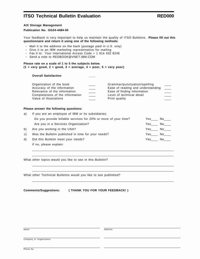
ITSO Technical Bulletin Evaluation RED000
AIX Storage Management
Publication No. GG24-4484-00
Your feedback is very important to help us maintain the quality of ITSO Bulletins. Please fill out thisquestionnaire and return it using one of the following methods:
• Mail it to the address on the back (postage paid in U.S. only)• Give it to an IBM marketing representative for mailing• Fax it to: Your International Access Code + 1 914 432 8246• Send a note to [email protected]
Please rate on a scale of 1 to 5 the subjects below.(1 = very good, 2 = good, 3 = average, 4 = poor, 5 = very poor)
Overall Satisfaction ____
Organization of the bookAccuracy of the informationRelevance of the informationCompleteness of the informationValue of illustrations
____________________
Grammar/punctuation/spell ingEase of reading and understandingEase of finding informationLevel of technical detailPrint quality
____________________
Please answer the following questions:
a) If you are an employee of IBM or its subsidiaries:
Do you provide billable services for 20% or more of your time? Yes____ No____
Are you in a Services Organization? Yes____ No____
b) Are you working in the USA? Yes____ No____
c) Was the Bulletin published in time for your needs? Yes____ No____
d) Did this Bulletin meet your needs? Yes____ No____
If no, please explain:
What other topics would you like to see in this Bulletin?
What other Technical Bulletins would you like to see published?
Comments/Suggestions: ( THANK YOU FOR YOUR FEEDBACK! )
Name Address
Company or Organizat ion
Phone No.
Cut or FoldAlong Line
Cut or FoldAlong Line
ITSO Technical Bulletin Evaluation RED000GG24-4484-00 IBML
Fold and Tape Please do not staple Fold and Tape
NO POSTAGENECESSARYIF MAILED IN THEUNITED STATES
BUSINESS REPLY MAILFIRST-CLASS MAIL PERMIT NO. 40 ARMONK, NEW YORK
POSTAGE WILL BE PAID BY ADDRESSEE
IBM International Technical Support OrganizationDepartment 948, Building 821Internal Zip 283411400 BURNET ROADAUSTIN TXUSA 78758-3493
Fold and Tape Please do not staple Fold and Tape
GG24-4484-00


IBML
Printed in U.S.A.
GG24-4484-00