Embed Size (px)
Citation preview
ÄKTA™ pilot 600User Manual
Table of Contents41 Introduction ..........................................................................................................51.1 About this manual ................................................................................................................................61.2 Important user information .............................................................................................................91.3 Associated documentation ..............................................................................................................
152 System description ..............................................................................................162.1 Description of the ÄKTA pilot 600 instrument ..........................................................................192.2 Flow path ..................................................................................................................................................212.3 Accessories ..............................................................................................................................................272.4 Instrument Configuration software .............................................................................................
293 Description of modules .......................................................................................303.1 External air sensors (optional) .........................................................................................................333.2 Inlet valves ...............................................................................................................................................353.3 Pumps ........................................................................................................................................................373.4 Flow restrictor ........................................................................................................................................393.5 Mixer valve and mixer (optional) ...................................................................................................413.6 Air trap valve and air trap .................................................................................................................453.7 In-line filter (optional) ..........................................................................................................................473.8 Column valve ..........................................................................................................................................513.9 Conductivity monitor ..........................................................................................................................533.10 UV monitor ...............................................................................................................................................553.11 pH monitor (optional) .........................................................................................................................573.12 Outlet valves ...........................................................................................................................................
594 Operation ..............................................................................................................604.1 Sample application ..............................................................................................................................614.1.1 Background considerations ......................................................................................................634.1.2 Apply sample from a system inlet ..........................................................................................684.1.3 Apply sample from a Superloop ..............................................................................................714.2 Fractionation ..........................................................................................................................................774.3 Intelligent packing ................................................................................................................................814.4 Dual pump flow .....................................................................................................................................844.5 Pressure control ....................................................................................................................................874.6 Performing runs in a cold environment .....................................................................................
895 Maintenance .........................................................................................................925.1 Maintenance manager ......................................................................................................................935.2 Maintenance schedule .......................................................................................................................955.3 Cleaning procedures ...........................................................................................................................965.3.1 Clean the conductivity flow cell ...............................................................................................985.3.2 Clean the UV flow cell ..................................................................................................................
1005.4 Calibration procedures ......................................................................................................................1015.4.1 Reset the pressure sensors ........................................................................................................
2 ÄKTA pilot 600 User Manual 29274559 AA
Table of Contents
1045.4.2 Calibrate the conductivity monitor .........................................................................................1095.5 Replacement procedures ..................................................................................................................1115.5.1 Replace the pH electrode ............................................................................................................1125.5.2 Replace the Mixer module ..........................................................................................................1145.5.3 Replace the UV monitor flow cell ............................................................................................1185.5.4 Replace valve fronts ......................................................................................................................
1196 Performance tests ...............................................................................................1206.1 When to run performance tests ....................................................................................................1226.2 How to run performance tests .......................................................................................................1266.3 How to evaluate performance tests ............................................................................................
1287 Troubleshooting ...................................................................................................1297.1 System leakage test failure ..............................................................................................................1307.2 System backpressure test failure ..................................................................................................1317.3 System test failure ................................................................................................................................1337.4 Other performance tests ...................................................................................................................
1348 Reference information ........................................................................................1358.1 Component volumes ...........................................................................................................................1368.2 Ordering information ..........................................................................................................................
137Index .......................................................................................................................
ÄKTA pilot 600 User Manual 29274559 AA 3
Table of Contents
1 Introduction
About this chapterThis chapter contains important user information, descriptions of safety notices, intendeduse of the ÄKTA pilot 600 system, and lists of associated documentation.
In this chapterThis chapter contains the following sections:
See pageSection
51.1 About this manual
61.2 Important user information
91.3 Associated documentation
4 ÄKTA pilot 600 User Manual 29274559 AA
1 Introduction
1.1 About this manual
Purpose of this manualThe User Manual provides you with in-depth instructions and information for using theÄKTA pilot 600 system. Basic instructions including important safety information aregiven in the ÄKTA pilot 600 Operating Instructions.
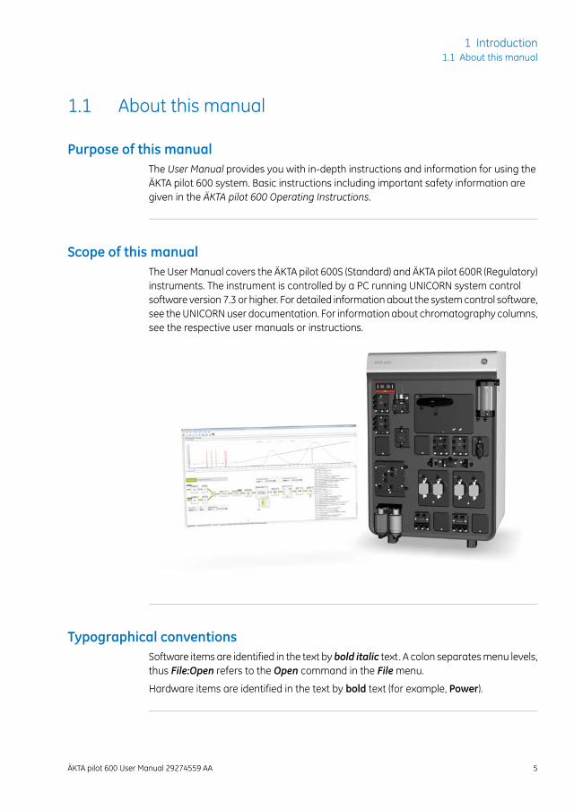
Scope of this manualThe User Manual covers the ÄKTA pilot 600S (Standard) and ÄKTA pilot 600R (Regulatory)instruments. The instrument is controlled by a PC running UNICORN system controlsoftware version 7.3 or higher. For detailed informationabout the systemcontrol software,see theUNICORNuser documentation. For information about chromatography columns,see the respective user manuals or instructions.
Typographical conventionsSoftware items are identified in the text by bold italic text. A colon separatesmenu levels,thus File:Open refers to the Open command in the Filemenu.
Hardware items are identified in the text by bold text (for example, Power).
ÄKTA pilot 600 User Manual 29274559 AA 5
1 Introduction1.1 About this manual
1.2 Important user information
Read the Operating Instructionsbefore using the product
All usersmust read the entireÄKTApilot 600Operating Instructionsbefore installing,operating or maintaining the product.
Always keep the Operating Instructions at hand when operating the product.
Do not operate the product in any other way than described in the user documentation.If you do, you may be exposed to hazards that can lead to personal injury and you maycause damage to the equipment.
Intended use of the productThe ÄKTA pilot 600 system is a low-pressure automated liquid chromatography systemproviding:
• precision transportation of fluids to and from chromatography columns of varyingsizes,
• detection and monitoring of UV absorbance, conductivity, and pH,
• fractionation of column eluate.
The system is intended for process development, scale up and scale down of processes,aswell as sanitary production ofmaterial for pre-clinical and clinical phases of applicablescale. The working flow rate range is 0.1 to 600 mL/min, (or 600 to 1200 mL/min usingdual pump flow), at pressures up to 2 MPa (20 bar).
Process engineers, process operators and other trained laboratory personnel are theintended users of the ÄKTA pilot 600 system.
The ÄKTA pilot 600 system shall not be used in any clinical procedures, or for diagnosticpurposes.
The ÄKTA pilot 600 system shall not be used in a potentially explosive atmosphere or forhandling flammable liquids.
6 ÄKTA pilot 600 User Manual 29274559 AA
1 Introduction1.2 Important user information
PrerequisitesIn order to follow this manual and use the system in the manner it is intended:
• The user should have a general understanding of how the computer andMicrosoft®
Windows® work.
• The user must understand the concepts of liquid chromatography.
• The user must have read and understood the Safety instructions chapter in theÄKTA pilot 600 Operating Instructions.
• The ÄKTA pilot 600 system must have been installed according to the instructionsin the ÄKTA pilot 600 Operating Instructions.
• A user accountmust have been created according to theUNICORN™Administrationand Technical Manual.
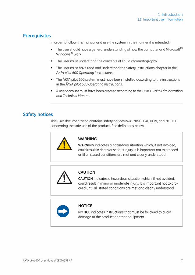
Safety noticesThis user documentation contains safety notices (WARNING, CAUTION, and NOTICE)concerning the safe use of the product. See definitions below.
WARNINGWARNING indicates a hazardous situation which, if not avoided,could result in death or serious injury. It is important not to proceeduntil all stated conditions are met and clearly understood.
CAUTIONCAUTION indicates a hazardous situation which, if not avoided,could result in minor or moderate injury. It is important not to pro-ceed until all stated conditions are met and clearly understood.
NOTICENOTICE indicates instructions that must be followed to avoiddamage to the product or other equipment.
ÄKTA pilot 600 User Manual 29274559 AA 7
1 Introduction1.2 Important user information
Notes and tipsA note is used to indicate information that is important for trouble-free andoptimal use of the product.
Note:
A tip contains useful information that can improve or optimize your procedures.Tip:
8 ÄKTA pilot 600 User Manual 29274559 AA
1 Introduction1.2 Important user information
1.3 Associated documentation
IntroductionThis section describes the user documentation that is delivered with the product, andhow to find related literature that can be downloaded or ordered from GE.
User documentation forÄKTA pilot 600
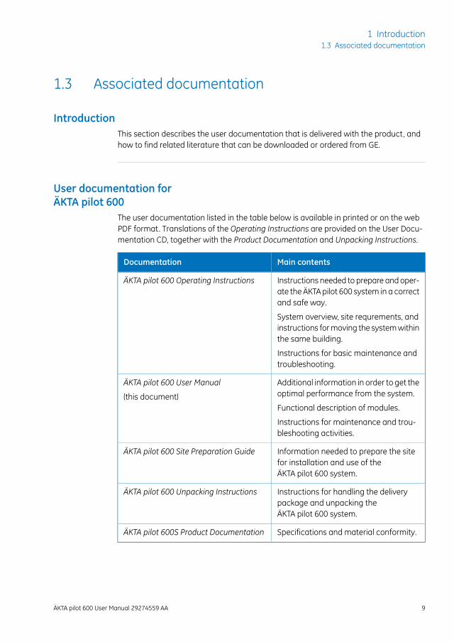
The user documentation listed in the table below is available in printed or on the webPDF format. Translations of the Operating Instructions are provided on the User Docu-mentation CD, together with the Product Documentation and Unpacking Instructions.
Main contentsDocumentation
Instructions needed to prepare andoper-ate the ÄKTA pilot 600 system in a correctand safe way.
ÄKTA pilot 600 Operating Instructions
System overview, site requrements, andinstructions formoving the systemwithinthe same building.
Instructions for basic maintenance andtroubleshooting.
Additional information in order to get theoptimal performance from the system.
ÄKTA pilot 600 User Manual
(this document)Functional description of modules.
Instructions for maintenance and trou-bleshooting activities.
Information needed to prepare the sitefor installation and use of theÄKTA pilot 600 system.
ÄKTA pilot 600 Site Preparation Guide
Instructions for handling the deliverypackage and unpacking theÄKTA pilot 600 system.
ÄKTA pilot 600 Unpacking Instructions
Specifications and material conformity.ÄKTA pilot 600S Product Documentation
ÄKTA pilot 600 User Manual 29274559 AA 9
1 Introduction1.3 Associated documentation
Product documentation binders(Regulatory version only)
In addition to the user documentation, the documentation package supplied withÄKTA pilot 600R (Regulatory systems) also includes product documentation binderscontaining detailed specifications and traceability documents, specific to the individualsystem.
Formore information about the ÄKTA pilot 600R instrument, see Standard and Regulatoryversions of the instrument, on page 16.
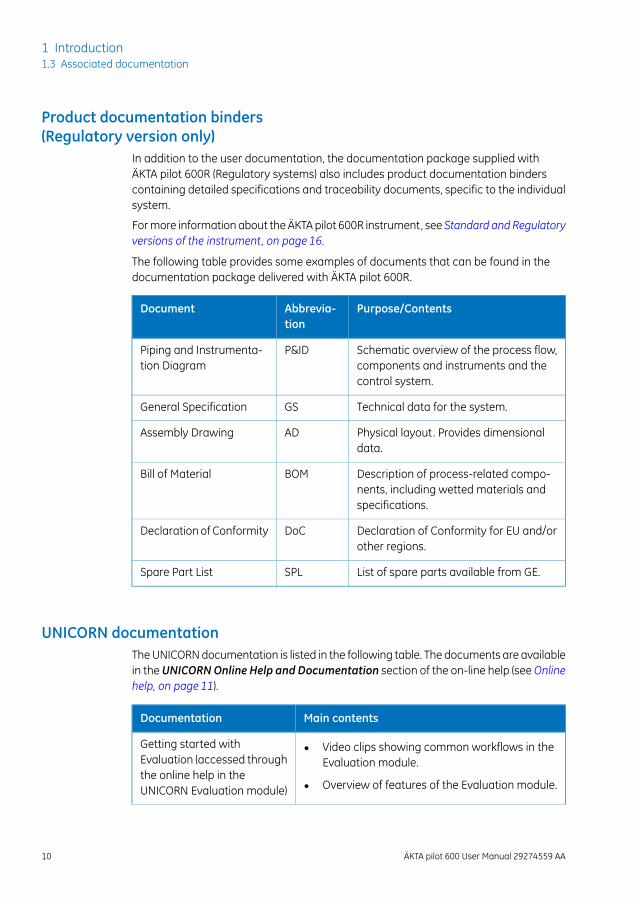
The following table provides some examples of documents that can be found in thedocumentation package delivered with ÄKTA pilot 600R.
Purpose/ContentsAbbrevia-tion
Document
Schematic overview of the process flow,components and instruments and thecontrol system.
P&IDPiping and Instrumenta-tion Diagram
Technical data for the system.GSGeneral Specification
Physical layout. Provides dimensionaldata.
ADAssembly Drawing
Description of process-related compo-nents, including wetted materials andspecifications.
BOMBill of Material
Declaration of Conformity for EU and/orother regions.
DoCDeclaration of Conformity
List of spare parts available from GE.SPLSpare Part List
UNICORN documentationTheUNICORNdocumentation is listed in the following table. The documents are availablein theUNICORNOnline Help and Documentation section of the on-line help (seeOnlinehelp, on page 11).
Main contentsDocumentation
• Video clips showing common workflows in theEvaluation module.
• Overview of features of the Evaluation module.
Getting started withEvaluation (accessed throughthe online help in theUNICORN Evaluation module)
10 ÄKTA pilot 600 User Manual 29274559 AA
1 Introduction1.3 Associated documentation
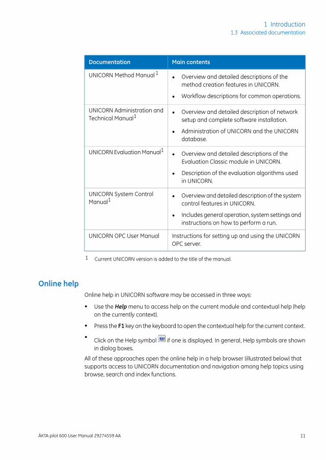
Main contentsDocumentation
• Overview and detailed descriptions of themethod creation features in UNICORN.
• Workflow descriptions for common operations.
UNICORN Method Manual1
• Overview and detailed description of networksetup and complete software installation.
• Administration of UNICORN and the UNICORNdatabase.
UNICORN Administration andTechnical Manual1
• Overview and detailed descriptions of theEvaluation Classic module in UNICORN.
• Description of the evaluation algorithms usedin UNICORN.
UNICORNEvaluationManual1
• Overviewanddetailed description of the systemcontrol features in UNICORN.
• Includes general operation, system settings andinstructions on how to perform a run.
UNICORN System ControlManual1
Instructions for setting up and using the UNICORNOPC server.
UNICORN OPC User Manual
1 Current UNICORN version is added to the title of the manual.
Online helpOnline help in UNICORN software may be accessed in three ways:
• Use the Helpmenu to access help on the current module and contextual help (helpon the currently context).
• Press the F1 key on the keyboard to open the contextual help for the current context.
• Click on the Help symbol if one is displayed. In general, Help symbols are shownin dialog boxes.
All of these approaches open the online help in a help browser (illustrated below) thatsupports access to UNICORN documentation and navigation among help topics usingbrowse, search and index functions.
ÄKTA pilot 600 User Manual 29274559 AA 11
1 Introduction1.3 Associated documentation
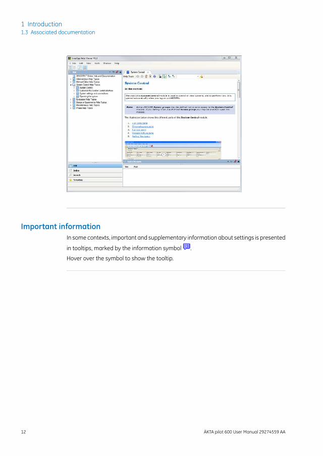
Important informationIn some contexts, important and supplementary information about settings is presented
in tooltips, marked by the information symbol .
Hover over the symbol to show the tooltip.
12 ÄKTA pilot 600 User Manual 29274559 AA
1 Introduction1.3 Associated documentation
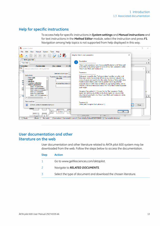
Help for specific instructionsTo access help for specific instructions in System settings andManual instructions andfor text instructions in theMethod Editormodule, select the instruction and press F1.Navigation among help topics is not supported from help displayed in this way.
User documentation and otherliterature on the web
User documentation and other literature related to ÄKTA pilot 600 system may bedownloaded from the web. Follow the steps below to access the documentation.
ActionStep
Go to www.gelifesciences.com/aktapilot.1
Navigate to RELATED DOCUMENTS.2
Select the type of document and download the chosen literature.3
ÄKTA pilot 600 User Manual 29274559 AA 13
1 Introduction1.3 Associated documentation
Access documentation frommobile units
Scan the code using your mobile phone or tablet computer to access the product pagefor ÄKTA pilot 600. Select documents to download under RELATED DOCUMENTS.
14 ÄKTA pilot 600 User Manual 29274559 AA
1 Introduction1.3 Associated documentation
2 System description
About this chapterThis chapter gives an overview of the ÄKTA pilot 600 instrument, available accessories,and the Instrument Configuration software.
In this chapterThis chapter contains the following sections:
See pageSection
162.1 Description of the ÄKTA pilot 600 instrument
192.2 Flow path
212.3 Accessories
272.4 Instrument Configuration software
ÄKTA pilot 600 User Manual 29274559 AA 15
2 System description
2.1 Description of the ÄKTA pilot 600 instrument
IntroductionThis section gives an overview of the instrument and the available modules.
Standard and Regulatoryversions of the instrument
The ÄKTA pilot 600 instrument is available in two versions:
• ÄKTA pilot 600S, Standard instrument, with the possibility to install optionalmodules.
• ÄKTA pilot 600R, Regulatory instrument. The ÄKTA pilot 600R system is supplied fullyconfigured according to the purchase specifications, and is tested at the factory.ÄKTA pilot 600R is delivered with the additional instrument specific, detailed docu-mentation. Installing, removing or moving modules will make the documentationinvalid.
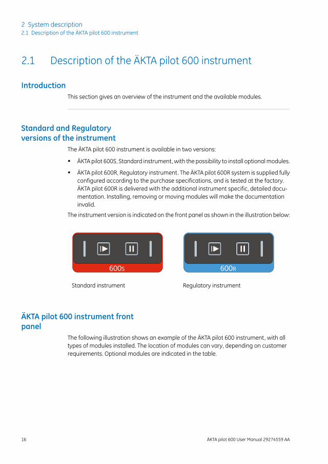
The instrument version is indicated on the front panel as shown in the illustration below:
600R600S
Regulatory instrumentStandard instrument
ÄKTA pilot 600 instrument frontpanel
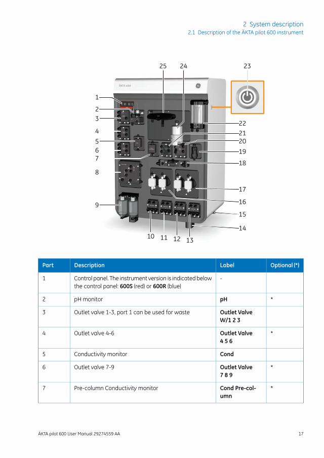
The following illustration shows an example of the ÄKTA pilot 600 instrument, with alltypes of modules installed. The location of modules can vary, depending on customerrequirements. Optional modules are indicated in the table.
16 ÄKTA pilot 600 User Manual 29274559 AA
2 System description2.1 Description of the ÄKTA pilot 600 instrument
1
23
45
76
8
9
12 1311
16
14
15
17
18
19
202122
2325 24
10
Optional (*)LabelDescriptionPart
-Control panel. The instrument version is indicated belowthe control panel: 600S (red) or 600R (blue)
1
*pHpH monitor2
Outlet ValveW/1 2 3
Outlet valve 1-3, port 1 can be used for waste3
*Outlet Valve4 5 6
Outlet valve 4-64
CondConductivity monitor5
*Outlet Valve7 8 9
Outlet valve 7-96
*Cond Pre-col-umn
Pre-column Conductivity monitor7
ÄKTA pilot 600 User Manual 29274559 AA 17
2 System description2.1 Description of the ÄKTA pilot 600 instrument
Optional (*)LabelDescriptionPart
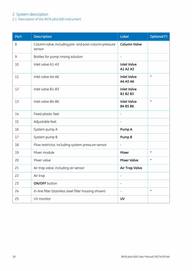
Column ValveColumn valve, including pre- and post-columnpressuresensor
8
-Bottles for pump rinsing solution9
Inlet ValveA1 A2 A3
Inlet valve A1-A310
*Inlet ValveA4 A5 A6
Inlet valve A4-A611
Inlet ValveB1 B2 B3
Inlet valve B1-B312
*Inlet ValveB4 B5 B6
Inlet valve B4-B613
-Fixed plastic feet14
-Adjustable feet15
Pump ASystem pump A16
Pump BSystem pump B17
-Flow restrictor, including system pressure sensor18
*MixerMixer module19
*Mixer ValveMixer valve20
Air Trap ValveAir trap valve, including air sensor21
-Air trap22
-ON/OFF button23
*-In-line filter (stainless steel filter housing shown)24
UVUV monitor25
18 ÄKTA pilot 600 User Manual 29274559 AA
2 System description2.1 Description of the ÄKTA pilot 600 instrument
2.2 Flow path
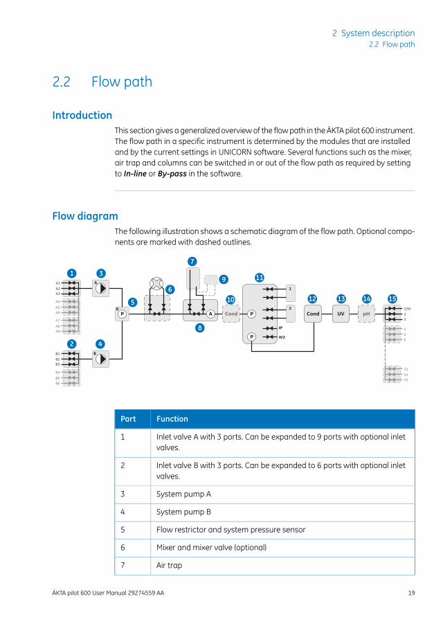
IntroductionThis section gives a generalizedoverviewof the flowpath in theÄKTApilot 600 instrument.The flow path in a specific instrument is determined by the modules that are installedand by the current settings in UNICORN software. Several functions such as the mixer,air trap and columns can be switched in or out of the flow path as required by settingto In-line or By-pass in the software.
Flow diagramThe following illustration shows a schematic diagram of the flow path. Optional compo-nents are marked with dashed outlines.
B1B2B3
A1A2A3
A5
A4
A6
A8
A7
A9
B5
B4
B6
1/W23
P CondCond UV pH
P
APR
B
A1
IP
W2
2
456
131415
1
2
3
4
5
6
8
9
7
11
10 12 13 14 15
FunctionPart
Inlet valve A with 3 ports. Can be expanded to 9 ports with optional inletvalves.
1
Inlet valve B with 3 ports. Can be expanded to 6 ports with optional inletvalves.
2
System pump A3
System pump B4
Flow restrictor and system pressure sensor5
Mixer and mixer valve (optional)6
Air trap7
ÄKTA pilot 600 User Manual 29274559 AA 19
2 System description2.2 Flow path
FunctionPart
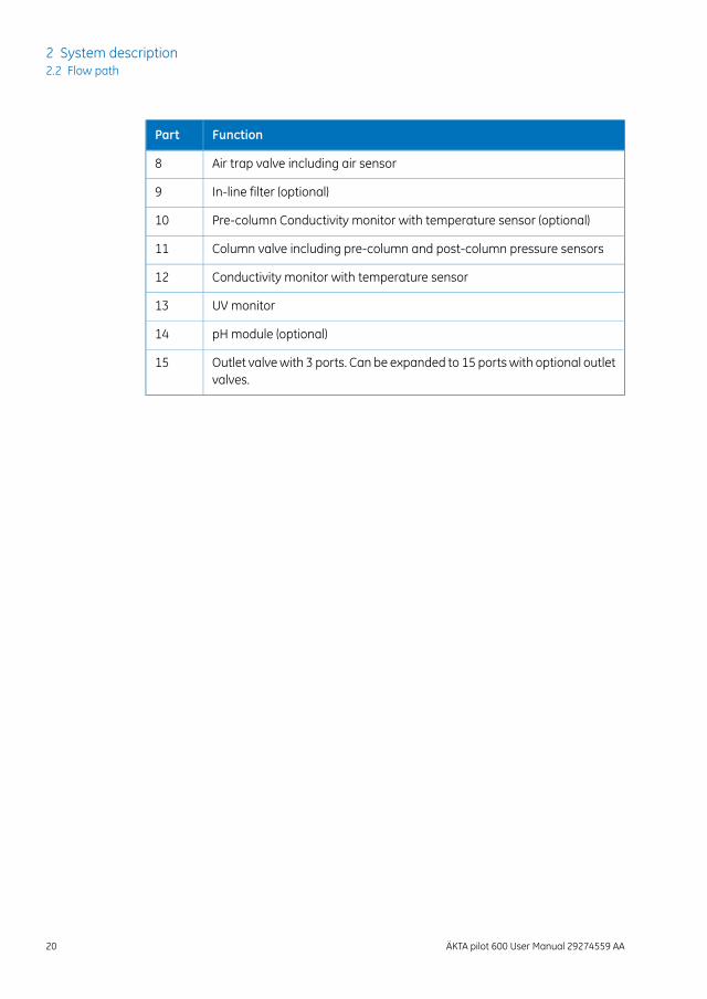
Air trap valve including air sensor8
In-line filter (optional)9
Pre-column Conductivity monitor with temperature sensor (optional)10
Column valve including pre-column and post-column pressure sensors11
Conductivity monitor with temperature sensor12
UV monitor13
pH module (optional)14
Outlet valvewith 3 ports. Can be expanded to 15 ports with optional outletvalves.
15
20 ÄKTA pilot 600 User Manual 29274559 AA
2 System description2.2 Flow path
2.3 Accessories
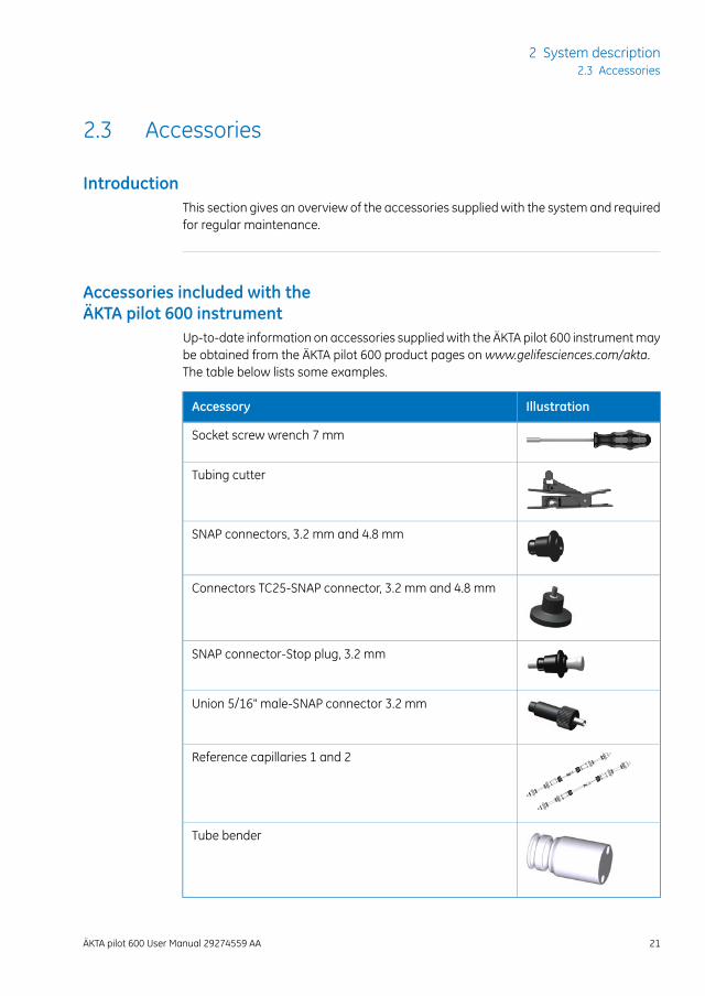
IntroductionThis section gives an overview of the accessories supplied with the system and requiredfor regular maintenance.
Accessories included with theÄKTA pilot 600 instrument
Up-to-date information on accessories suppliedwith the ÄKTA pilot 600 instrumentmaybe obtained from the ÄKTA pilot 600 product pages on www.gelifesciences.com/akta.The table below lists some examples.
IllustrationAccessory
Socket screw wrench 7 mm
Tubing cutter
SNAP connectors, 3.2 mm and 4.8 mm
Connectors TC25-SNAP connector, 3.2 mm and 4.8 mm
SNAP connector-Stop plug, 3.2 mm
Union 5/16" male-SNAP connector 3.2 mm
Reference capillaries 1 and 2
Tube bender
ÄKTA pilot 600 User Manual 29274559 AA 21
2 System description2.3 Accessories
Using the Tube benderThe Tube bender, provided as an accessory with the instrument, helps in bending tubingwithout introducing kinks. Short lengths of tubing, especially the i.d. 4.8 mm tubing onthe inlet side of the pumps, are particularly susceptible to kinking.
Use the Tube bender as described in the steps below.
ActionStep
Mount the Tube bender onmounting pins on the front of the instrument, forexample, the mounting pins for the in-line filter holder.
1
The Tube bender can also be used while held in the hand.
Pull the tubing around the groove in the Tube bender until a suitable bendis obtained. Use the wider groove for i.d. 4.8 mm tubing and the narrowerfor i.d. 3.2 mm tubing.
2
Optional accessoriesThe following optional accessories are available:
• Extension box for optional modules
• Extension stand for columns and accessories
• I/O-box to connect external equipment to the ÄKTA pilot 600 instrument
• Module front panel with rails
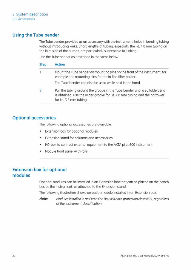
Extension box for optionalmodules
Optional modules can be installed in an Extension box that can be placed on the benchbeside the instrument, or attached to the Extension stand.
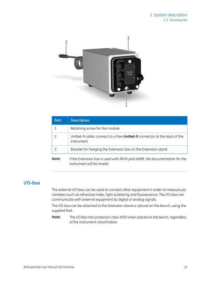
The following illustration shows an outlet module installed in an Extension box.
Modules installed in an ExtensionBoxwill have protection class IP21, regardlessof the instrument classification.
Note:
22 ÄKTA pilot 600 User Manual 29274559 AA
2 System description2.3 Accessories
1
32
DescriptionPart
Retaining screw for the module1
UniNet-9 cable: connect to a free UniNet-9 connector at the back of theinstrument
2
Bracket for hanging the Extension box on the Extension stand3
If the Extension box is used with ÄKTA pilot 600R, the documentation for theinstrument will be invalid.
Note:
I/O-boxThe external I/O-box can be used to connect other equipment in order to measure pa-rameters such as refractive index, light scattering and fluorescence. The I/O-box cancommunicate with external equipment by digital or analog signals.
The I/O-box can be attached to the Extension stand or placed on the bench, using thesupplied feet.
The I/O Box has protection class IP20 when placed on the bench, regardlessof the instrument classification.
Note:
ÄKTA pilot 600 User Manual 29274559 AA 23
2 System description2.3 Accessories
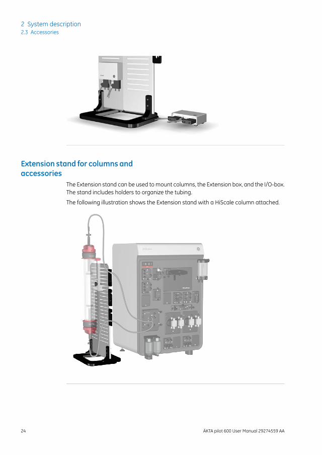
Extension stand for columnsandaccessories
The Extension stand can be used tomount columns, the Extension box, and the I/O-box.The stand includes holders to organize the tubing.
The following illustration shows the Extension stand with a HiScale column attached.
24 ÄKTA pilot 600 User Manual 29274559 AA
2 System description2.3 Accessories
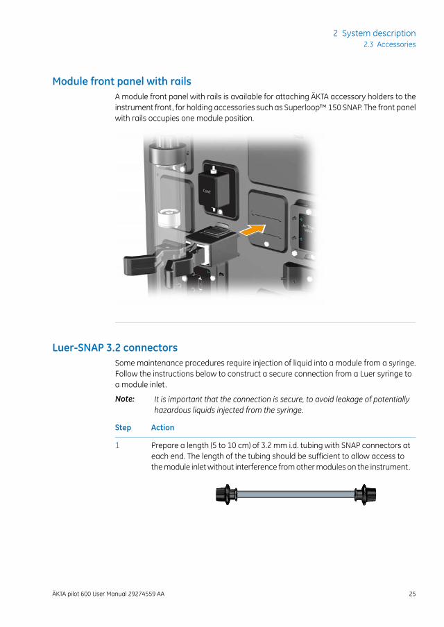
Module front panel with railsA module front panel with rails is available for attaching ÄKTA accessory holders to theinstrument front, for holding accessories such as Superloop™ 150 SNAP. The front panelwith rails occupies one module position.
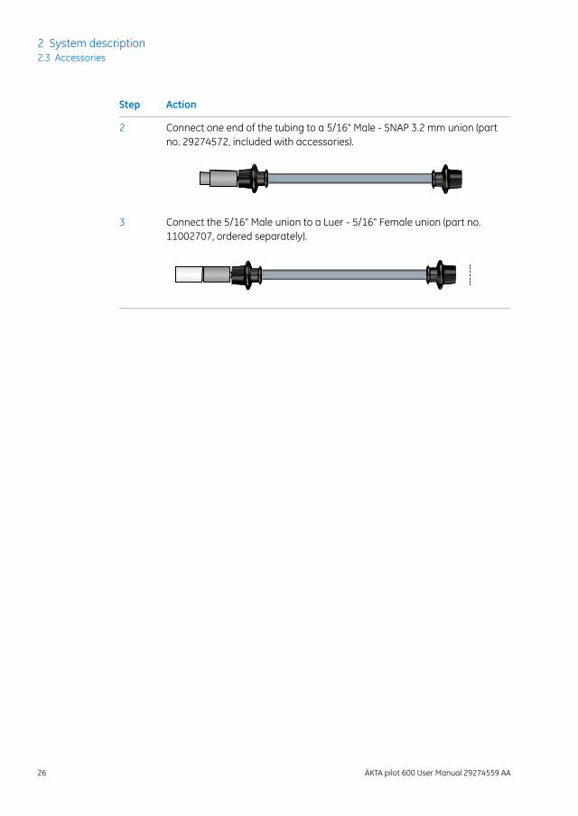
Luer-SNAP 3.2 connectorsSome maintenance procedures require injection of liquid into a module from a syringe.Follow the instructions below to construct a secure connection from a Luer syringe toa module inlet.
It is important that the connection is secure, to avoid leakage of potentiallyhazardous liquids injected from the syringe.
Note:
ActionStep
Prepare a length (5 to 10 cm) of 3.2 mm i.d. tubing with SNAP connectors ateach end. The length of the tubing should be sufficient to allow access tothemodule inletwithout interference fromothermodules on the instrument.
1
ÄKTA pilot 600 User Manual 29274559 AA 25
2 System description2.3 Accessories
ActionStep
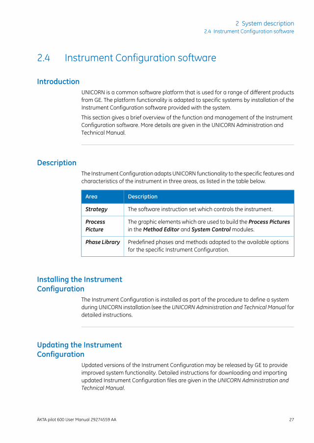
Connect one end of the tubing to a 5/16" Male - SNAP 3.2 mm union (partno. 29274572, included with accessories).
2
Connect the 5/16" Male union to a Luer - 5/16" Female union (part no.11002707, ordered separately).
3
26 ÄKTA pilot 600 User Manual 29274559 AA
2 System description2.3 Accessories
2.4 Instrument Configuration software
IntroductionUNICORN is a common software platform that is used for a range of different productsfrom GE. The platform functionality is adapted to specific systems by installation of theInstrument Configuration software provided with the system.
This section gives a brief overview of the function and management of the InstrumentConfiguration software. More details are given in the UNICORN Administration andTechnical Manual.
DescriptionThe Instrument Configuration adapts UNICORN functionality to the specific features andcharacteristics of the instrument in three areas, as listed in the table below.
DescriptionArea
The software instruction set which controls the instrument.Strategy
The graphic elements which are used to build the Process Picturesin theMethod Editor and System Controlmodules.
ProcessPicture
Predefined phases and methods adapted to the available optionsfor the specific Instrument Configuration.
Phase Library
Installing the InstrumentConfiguration
The Instrument Configuration is installed as part of the procedure to define a systemduring UNICORN installation (see the UNICORN Administration and Technical Manual fordetailed instructions.
Updating the InstrumentConfiguration
Updated versions of the Instrument Configuration may be released by GE to provideimproved system functionality. Detailed instructions for downloading and importingupdated Instrument Configuration files are given in the UNICORN Administration andTechnical Manual.
ÄKTA pilot 600 User Manual 29274559 AA 27
2 System description2.4 Instrument Configuration software
NOTICEIt is important that the correct Instrument Configuration for thesystem is downloaded and installed. The system will be unusableif an incorrect Instrument Configuration is installed.
28 ÄKTA pilot 600 User Manual 29274559 AA
2 System description2.4 Instrument Configuration software
3 Description of modules
About this chapterThis chapter gives additional information about the modules that are presented inÄKTA pilot 600 Operating Instructions. Technical details can be found in ÄKTA pilot 600SProduct Documentation, informationabout documentation for the R systemcanbe foundin ÄKTA pilot 600 Operating Instructions, and installation instructions can be found inrespective module installation instruction.
In this chapterThis chapter contains the following sections.
See pageSection
303.1 External air sensors (optional)
333.2 Inlet valves
353.3 Pumps
373.4 Flow restrictor
393.5 Mixer valve and mixer (optional)
413.6 Air trap valve and air trap
453.7 In-line filter (optional)
473.8 Column valve
513.9 Conductivity monitor
533.10 UV monitor
553.11 pH monitor (optional)
573.12 Outlet valves
ÄKTA pilot 600 User Manual 29274559 AA 29
3 Description of modules
3.1 External air sensors (optional)
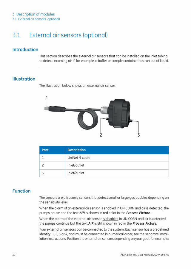
IntroductionThis section describes the external air sensors that can be installed on the inlet tubingto detect incoming air if, for example, a buffer or sample container has run out of liquid.
IllustrationThe illustration below shows an external air sensor.
1
2 3
DescriptionPart
UniNet-9 cable1
Inlet/outlet2
Inlet/outlet3
FunctionThe sensors are ultrasonic sensors that detect small or large gas bubbles depending onthe sensitivity level.
When the alarm of an external air sensor is enabled in UNICORN and air is detected, thepumps pause and the text AIR is shown in red color in the Process Picture.
When the alarm of the external air sensor is disabled in UNICORN and air is detected,the pumps continue but the text AIR is still shown in red in the Process Picture.
Four external air sensors can be connected to the system. Each sensor has a predefinedidentity, 1, 2, 3 or 4, and must be connected in numerical order, see the separate instal-lation instructions. Position the external air sensors depending on your goal, for example:
30 ÄKTA pilot 600 User Manual 29274559 AA
3 Description of modules3.1 External air sensors (optional)
• To apply all sample feed onto the column, use a short piece of tubing between theexternal air sensor and the inlet valve. Remember to have the air trap in-line whileapplying sample using short tubing and high flow rates, because air might pass be-yond the inlet valve.
• To prevent air entering the system flow path, place the external air sensor close tothe liquid container. When running high flow rates, use a long (>70 cm) piece oftubing between the external air sensor and the inlet valve to make sure no airreaches the inlet valve.
In a predefinedmethod, in the Sample application phase, the External air sensor 1 canbe used to facilitate sample application, see Section 4.1 Sample application, on page60.
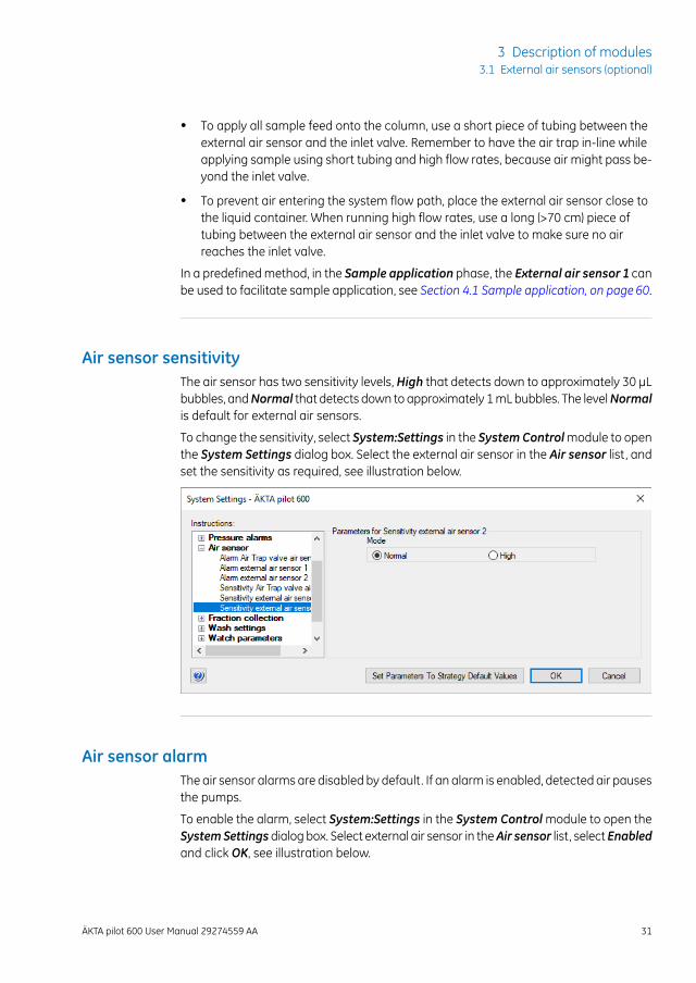
Air sensor sensitivityThe air sensor has two sensitivity levels, High that detects down to approximately 30 μLbubbles, andNormal that detects down to approximately 1mLbubbles. The levelNormalis default for external air sensors.
To change the sensitivity, select System:Settings in the SystemControlmodule to openthe System Settings dialog box. Select the external air sensor in the Air sensor list, andset the sensitivity as required, see illustration below.
Air sensor alarmThe air sensor alarms are disabled by default. If an alarm is enabled, detected air pausesthe pumps.
To enable the alarm, select System:Settings in the System Controlmodule to open theSystemSettingsdialog box. Select external air sensor in theAir sensor list, selectEnabledand click OK, see illustration below.
ÄKTA pilot 600 User Manual 29274559 AA 31
3 Description of modules3.1 External air sensors (optional)
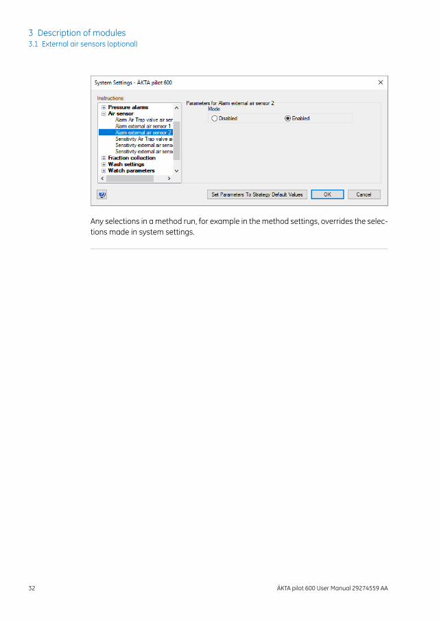
Any selections in amethod run, for example in themethod settings, overrides the selec-tions made in system settings.
32 ÄKTA pilot 600 User Manual 29274559 AA
3 Description of modules3.1 External air sensors (optional)
3.2 Inlet valves
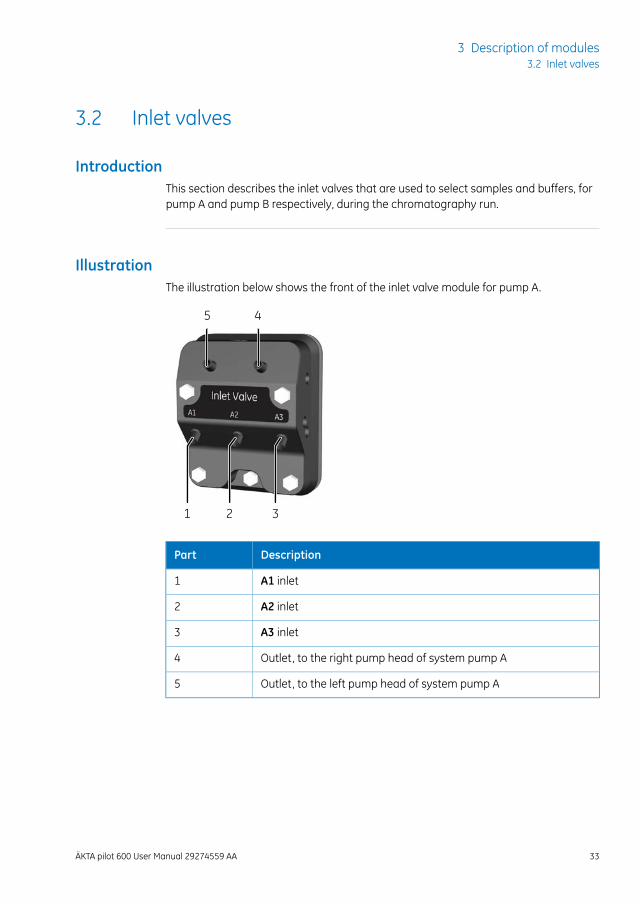
IntroductionThis section describes the inlet valves that are used to select samples and buffers, forpump A and pump B respectively, during the chromatography run.
IllustrationThe illustration below shows the front of the inlet valve module for pump A.
5
1
4
2 3
DescriptionPart
A1 inlet1
A2 inlet2
A3 inlet3
Outlet, to the right pump head of system pump A4
Outlet, to the left pump head of system pump A5
ÄKTA pilot 600 User Manual 29274559 AA 33
3 Description of modules3.2 Inlet valves
FunctionThe inlet valve modules consist of a number of membrane valves. The first A inlet port,A1, is used for buffer solution. A2 and A3 are used for sample or buffer solutions. If moreA inlets are required, up to three inlet valve modules can be installed which results innine A inlets.
The B inlets are used for buffer andwash solutions. If more B inlets are required, anotherB inlet module can be installed which results in six B inlets.
When running isocratic dual pump flow, make sure that the same buffer solu-tion is pumped in pump A and pump B. For example, place the A and B inletsin the same buffer container. See Section 4.4 Dual pump flow, on page 81.
Note:
Inlet tubingTubing with inner diameter 4.8 mm and SNAP 4.8 connectors is used on the valve inlets.An adapter can be used between the SNAP 4.8 connector and the larger TC25 clamp touse tubing with larger diameter. Tubing with larger diameter is needed in the followingcases:
• High viscosity solutions
• Long inlet tubing
• Tank or pipe with TC25 clamp
34 ÄKTA pilot 600 User Manual 29274559 AA
3 Description of modules3.2 Inlet valves
3.3 Pumps
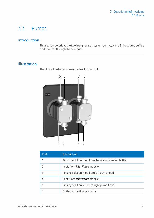
IntroductionThis section describes the two high precision system pumps, A and B, that pump buffersand samples through the flow path.
IllustrationThe illustration below shows the front of pump A.
5 6 7 8
2 3 41
DescriptionPart
Rinsing solution inlet, from the rinsing solution bottle1
Inlet, from Inlet Valvemodule2
Rinsing solution inlet, from left pump head3
Inlet, from Inlet Valvemodule4
Rinsing solution outlet, to right pump head5
Outlet, to the flow restrictor6
ÄKTA pilot 600 User Manual 29274559 AA 35
3 Description of modules3.3 Pumps
DescriptionPart
Rinsing solution outlet, to the rinsing solution bottle7
Outlet, to the flow restrictor8
FunctionEach system pumpmodule consists of two pump heads. The individual pump heads areidentical but actuated in opposite phase to each other. The two pistons and pumpheadswork alternately to give a continuous, low pulsation, liquid delivery. The two systempumps can be used individually or in combination, to generate isocratic or gradientelution in purification methods for flow rates up to 600 mL/min. The pumps can also beused in combination to generate dual flow in the flow range 600-1200 mL/min, for iso-cratic runs and limited gradient runs.
36 ÄKTA pilot 600 User Manual 29274559 AA
3 Description of modules3.3 Pumps
3.4 Flow restrictor
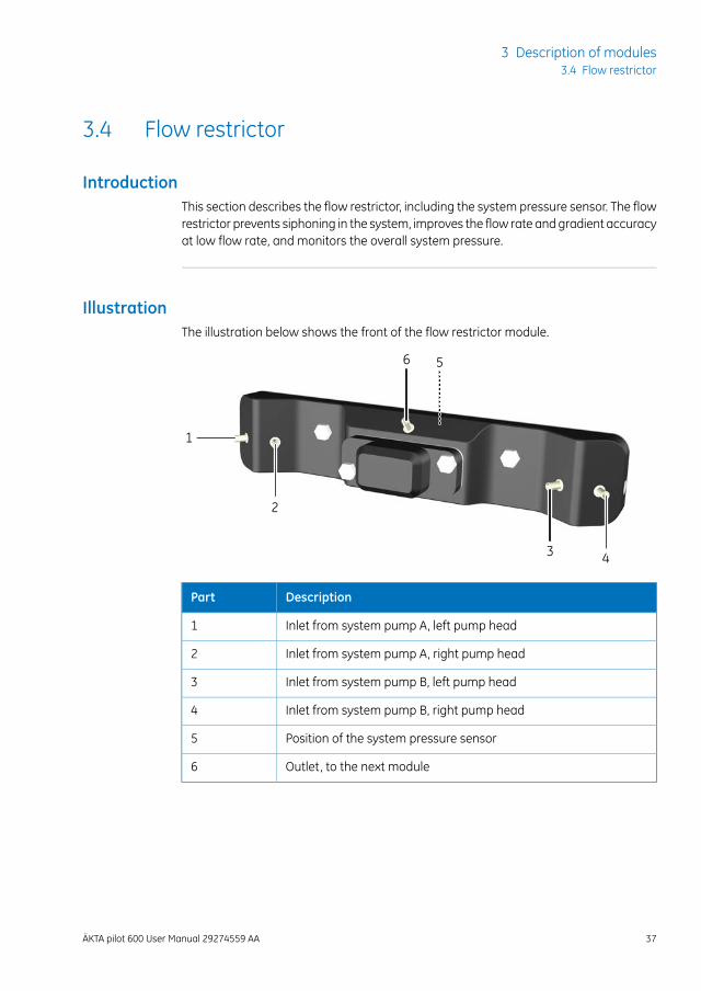
IntroductionThis section describes the flow restrictor, including the system pressure sensor. The flowrestrictor prevents siphoning in the system, improves the flow rate and gradient accuracyat low flow rate, and monitors the overall system pressure.
IllustrationThe illustration below shows the front of the flow restrictor module.
1
2
3 4
56
DescriptionPart
Inlet from system pump A, left pump head1
Inlet from system pump A, right pump head2
Inlet from system pump B, left pump head3
Inlet from system pump B, right pump head4
Position of the system pressure sensor5
Outlet, to the next module6
ÄKTA pilot 600 User Manual 29274559 AA 37
3 Description of modules3.4 Flow restrictor
FunctionThe module has two separate restrictors for A and B pumps respectively. The flow pathinside this module is designed to use inlets from pump A for sample application.
The system pressure sensor is located inside the flow restrictor module. This sensormeasures the pressure near the outlet, and UNICORN compares the value with thehighest allowed and the lowest allowed system pressure.
38 ÄKTA pilot 600 User Manual 29274559 AA
3 Description of modules3.4 Flow restrictor
3.5 Mixer valve and mixer (optional)
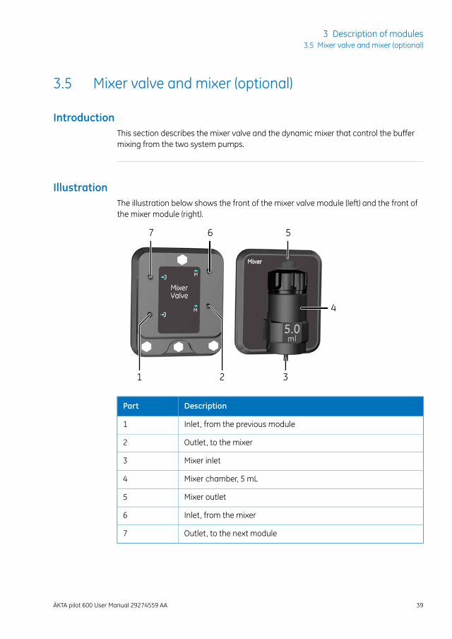
IntroductionThis section describes the mixer valve and the dynamic mixer that control the buffermixing from the two system pumps.
IllustrationThe illustration below shows the front of the mixer valve module (left) and the front ofthe mixer module (right).
4
7 6
321
5
DescriptionPart
Inlet, from the previous module1
Outlet, to the mixer2
Mixer inlet3
Mixer chamber, 5 mL4
Mixer outlet5
Inlet, from the mixer6
Outlet, to the next module7
ÄKTA pilot 600 User Manual 29274559 AA 39
3 Description of modules3.5 Mixer valve and mixer (optional)
FunctionThemixer valvemodule consists of a number ofmembrane valves. Themixer valve directsthe flow through themixer, or by-passes themixer, for example during sample application.
The mixer mixes the A and B buffers in a 5 mLmixer chamber to a homogeneous buffercomposition.
If the mixer is in-line, the mixer stir magnet starts and stops automatically at start andend of a method. If it is by-passed, it does not start.
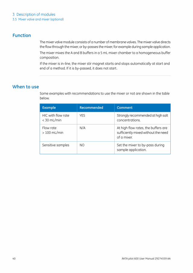
When to useSome examples with recommendations to use the mixer or not are shown in the tablebelow.
CommentRecommendedExample
Strongly recommendedat high saltconcentrations.
YESHIC with flow rate< 30 mL/min
At high flow rates, the buffers aresufficientlymixedwithout the needof a mixer.
N/AFlow rate> 100 mL/min
Set the mixer to by-pass duringsample application.
NOSensitive samples
40 ÄKTA pilot 600 User Manual 29274559 AA
3 Description of modules3.5 Mixer valve and mixer (optional)
3.6 Air trap valve and air trap
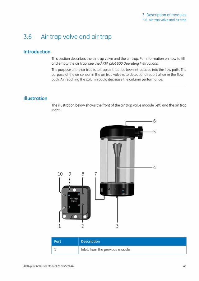
IntroductionThis section describes the air trap valve and the air trap. For information on how to filland empty the air trap, see the ÄKTA pilot 600 Operating Instructions.
The purpose of the air trap is to trap air that has been introduced into the flow path. Thepurpose of the air sensor in the air trap valve is to detect and report all air in the flowpath. Air reaching the column could decrease the column performance.
IllustrationThe illustration below shows the front of the air trap valve module (left) and the air trap(right).
1 2 3
4
5
6
78910
DescriptionPart
Inlet, from the previous module1
ÄKTA pilot 600 User Manual 29274559 AA 41
3 Description of modules3.6 Air trap valve and air trap
DescriptionPart
Outlet, to the air trap2
Air trap inlet3
Inlet funnel4
Manual vent valve knob5
Manual vent valve port6
Air trap outlet7
Inlet, from the air trap8
Position of the air sensor9
Outlet, to the next module10
FunctionAir is trapped in the upper part of the air trap if the lower part contains liquid. The inletfunnel is designed to increase the mixing functionality and decrease foaming. Duringruns with gradients and low flow rate, make sure that the liquid level stays below thefunnel top.
The air trap is in-line by default, but can be set in by-pass position using the air trapvalve. The valve consists of a number of membrane valves that allow the flow to be di-rected through the air trap or to by-pass the air trap.
An air sensor is positioned near the outlet of the air trap valve. It detects air even whenthe air trap is by-passed. If air is detected in the flow path, its presence is indicated inthe Process Picture. If air is detected in the flow path and the air sensor alarm is enabled,the run is paused.
When a large amount of air is trapped, the flow rate over the column is temporarily de-creased. If the air trap is completely filled with air, air is detected by the sensor.
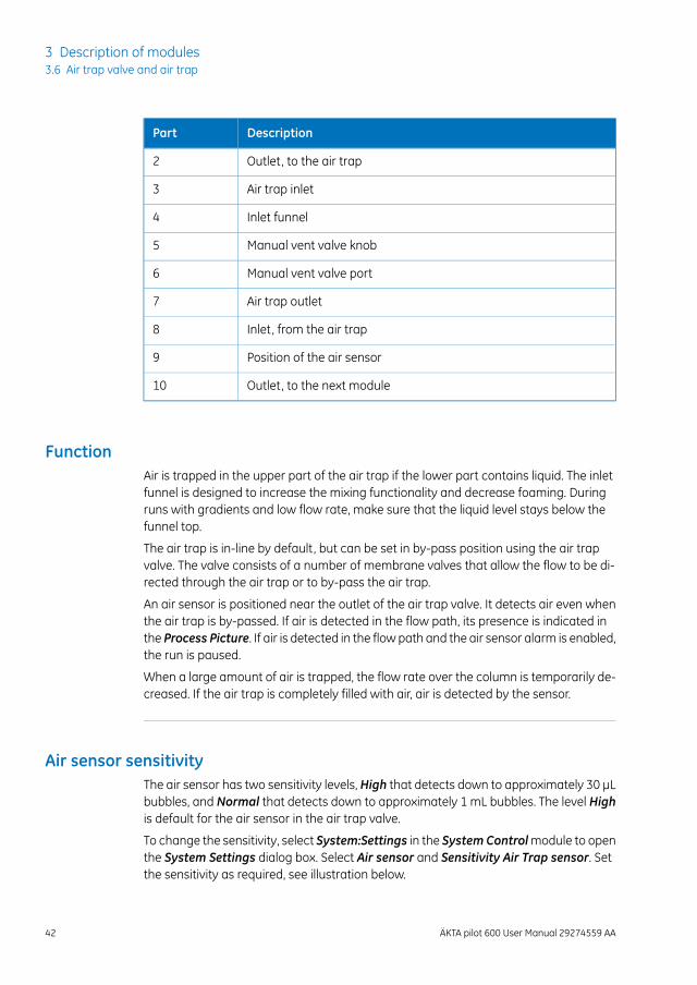
Air sensor sensitivityThe air sensor has two sensitivity levels, High that detects down to approximately 30 μLbubbles, and Normal that detects down to approximately 1 mL bubbles. The level Highis default for the air sensor in the air trap valve.
To change the sensitivity, select System:Settings in the SystemControlmodule to openthe System Settings dialog box. Select Air sensor and Sensitivity Air Trap sensor. Setthe sensitivity as required, see illustration below.
42 ÄKTA pilot 600 User Manual 29274559 AA
3 Description of modules3.6 Air trap valve and air trap
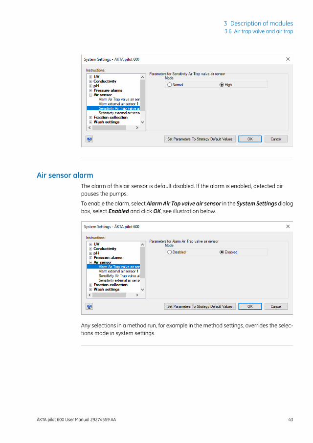
Air sensor alarmThe alarm of this air sensor is default disabled. If the alarm is enabled, detected airpauses the pumps.
To enable the alarm, selectAlarmAir Tap valve air sensor in the SystemSettings dialogbox, select Enabled and click OK, see illustration below.
Any selections in amethod run, for example in themethod settings, overrides the selec-tions made in system settings.
ÄKTA pilot 600 User Manual 29274559 AA 43
3 Description of modules3.6 Air trap valve and air trap
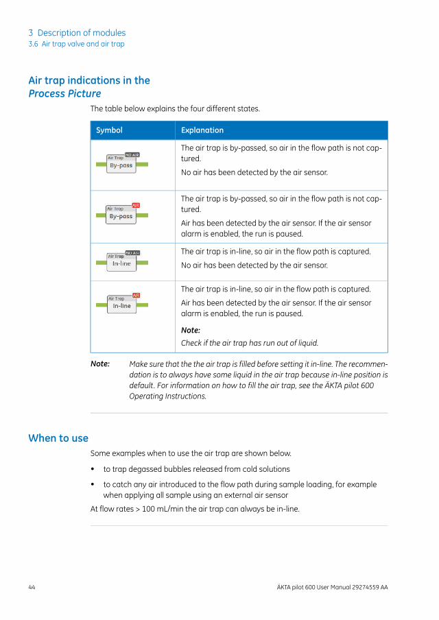
Air trap indications in theProcess Picture
The table below explains the four different states.
ExplanationSymbol
The air trap is by-passed, so air in the flow path is not cap-tured.
No air has been detected by the air sensor.
The air trap is by-passed, so air in the flow path is not cap-tured.
Air has been detected by the air sensor. If the air sensoralarm is enabled, the run is paused.
The air trap is in-line, so air in the flow path is captured.
No air has been detected by the air sensor.
The air trap is in-line, so air in the flow path is captured.
Air has been detected by the air sensor. If the air sensoralarm is enabled, the run is paused.
Note:
Check if the air trap has run out of liquid.
Make sure that the the air trap is filled before setting it in-line. The recommen-dation is to always have some liquid in the air trap because in-line position isdefault. For information on how to fill the air trap, see the ÄKTA pilot 600Operating Instructions.
Note:
When to useSome examples when to use the air trap are shown below.
• to trap degassed bubbles released from cold solutions
• to catch any air introduced to the flow path during sample loading, for examplewhen applying all sample using an external air sensor
At flow rates > 100 mL/min the air trap can always be in-line.
44 ÄKTA pilot 600 User Manual 29274559 AA
3 Description of modules3.6 Air trap valve and air trap
3.7 In-line filter (optional)
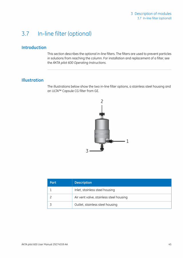
IntroductionThis section describes the optional in-line filters. The filters are used to prevent particlesin solutions from reaching the column. For installation and replacement of a filter, seethe ÄKTA pilot 600 Operating Instructions.
IllustrationThe illustrations below show the two in-line filter options, a stainless steel housing andan ULTA™ Capsule CG filter from GE.
1
2
3
DescriptionPart
Inlet, stainless steel housing1
Air vent valve, stainless steel housing2
Outlet, stainless steel housing3
ÄKTA pilot 600 User Manual 29274559 AA 45
3 Description of modules3.7 In-line filter (optional)
123
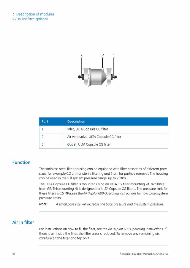
DescriptionPart
Inlet, ULTA Capsule CG filter1
Air vent valve, ULTA Capsule CG filter2
Outlet, ULTA Capsule CG filter3
FunctionThe stainless steel filter housing can be equipped with filter cassettes of different poresizes, for example 0.2 μm for sterile filtering and 3 µm for particle removal. The housingcan be used in the full system pressure range, up to 2 MPa.
The ULTA Capsule CG filter is mounted using an ULTA CG filter mounting kit, availablefrom GE. This mounting kit is designed for ULTA Capsule CG filters. The pressure limit forthese filters is 0.5MPa, see theÄKTA pilot 600Operating Instructions for how to set systempressure limits.
A small pore size will increase the back pressure and the system pressure.Note:
Air in filterFor instructions on how to fill the filter, see the ÄKTA pilot 600 Operating Instructions. Ifthere is air inside the filter, the filter area is reduced. To remove any remaining air,carefully tilt the filter and tap on it.
46 ÄKTA pilot 600 User Manual 29274559 AA
3 Description of modules3.7 In-line filter (optional)
3.8 Column valve
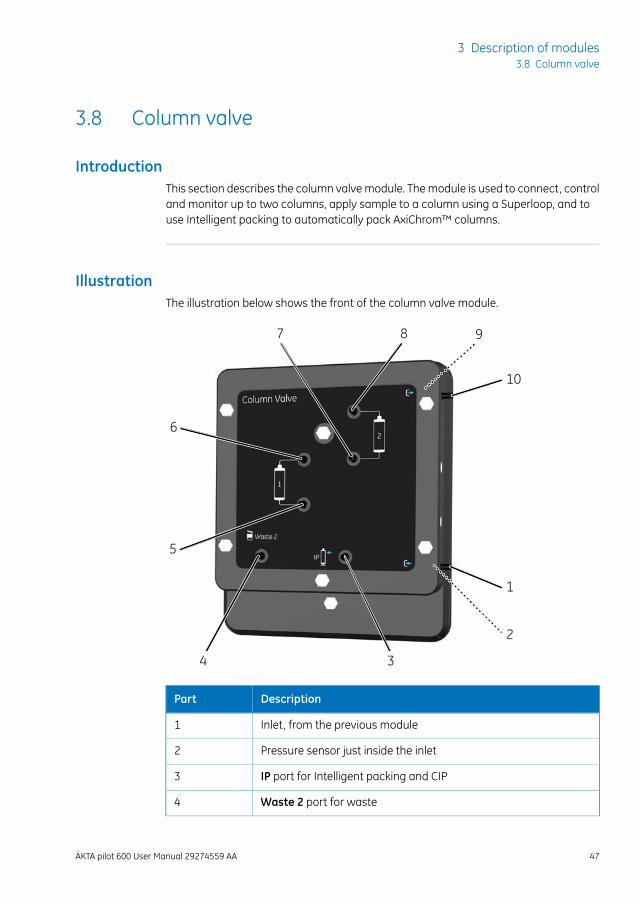
IntroductionThis section describes the column valve module. Themodule is used to connect, controland monitor up to two columns, apply sample to a column using a Superloop, and touse Intelligent packing to automatically pack AxiChrom™ columns.
IllustrationThe illustration below shows the front of the column valve module.
1
10
34
5
6
7 8 9
2
DescriptionPart
Inlet, from the previous module1
Pressure sensor just inside the inlet2
IP port for Intelligent packing and CIP3
Waste 2 port for waste4
ÄKTA pilot 600 User Manual 29274559 AA 47
3 Description of modules3.8 Column valve
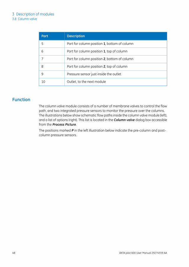
DescriptionPart
Port for column position 1, bottom of column5
Port for column position 1, top of column6
Port for column position 2, bottom of column7
Port for column position 2, top of column8
Pressure sensor just inside the outlet9
Outlet, to the next module10
FunctionThe column valve module consists of a number of membrane valves to control the flowpath, and two integrated pressure sensors to monitor the pressure over the columns.The illustrations below show schematic flow paths inside the column valvemodule (left),and a list of options (right). This list is located in the Column valve dialog box accessiblefrom the Process Picture.
The positions marked P in the left illustration below indicate the pre-column and post-column pressure sensors.
48 ÄKTA pilot 600 User Manual 29274559 AA
3 Description of modules3.8 Column valve
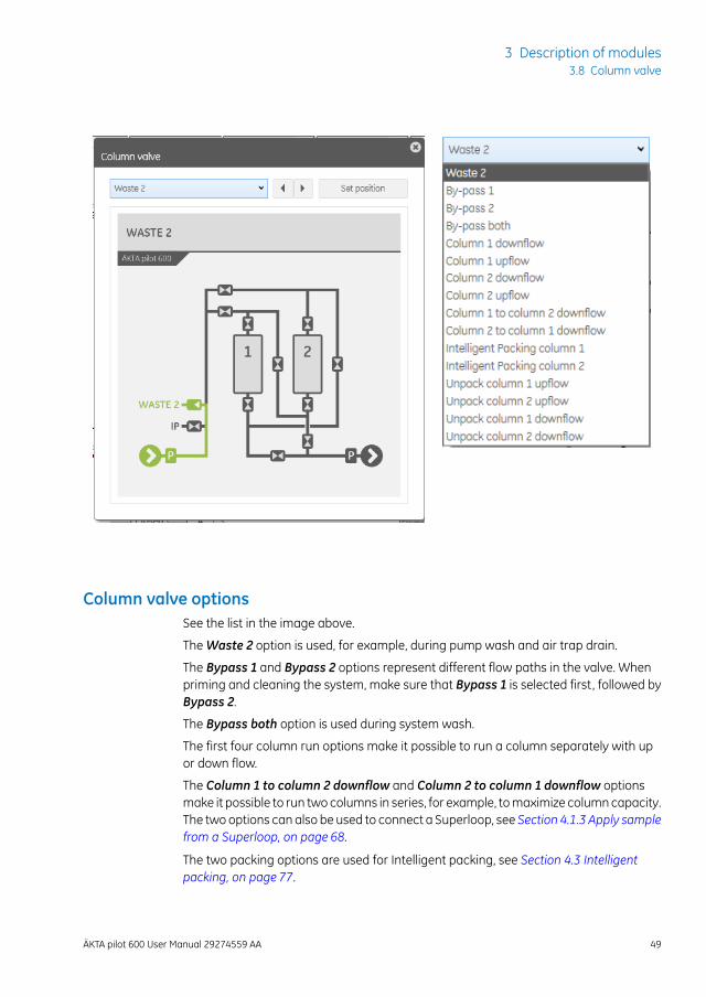
Column valve optionsSee the list in the image above.
TheWaste 2 option is used, for example, during pump wash and air trap drain.
The Bypass 1 and Bypass 2 options represent different flow paths in the valve. Whenpriming and cleaning the system, make sure that Bypass 1 is selected first, followed byBypass 2.
The Bypass both option is used during system wash.
The first four column run options make it possible to run a column separately with upor down flow.
The Column 1 to column 2 downflow and Column 2 to column 1 downflow optionsmake it possible to run two columns in series, for example, tomaximize columncapacity.The two options can also be used to connect a Superloop, see Section 4.1.3 Apply samplefrom a Superloop, on page 68.
The two packing options are used for Intelligent packing, see Section 4.3 Intelligentpacking, on page 77.
ÄKTA pilot 600 User Manual 29274559 AA 49
3 Description of modules3.8 Column valve
The four options for unpacking are used to simplify unpacking of columns. Before usingan unpacking option, make sure to read each column instruction.
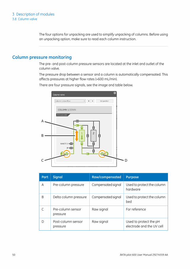
Column pressure monitoringThe pre- and post-column pressure sensors are located at the inlet and outlet of thecolumn valve.
The pressure drop between a sensor and a column is automatically compensated. Thisaffects pressures at higher flow rates (>600 mL/min).
There are four pressure signals, see the image and table below.
A
B
C D
PurposeRaw/compensatedSignalPart
Used to protect the columnhardware
CompensatedsignalPre-column pressureA
Used to protect the columnbed
CompensatedsignalDelta column pressureB
For referenceRaw signalPre-column sensorpressure
C
Used to protect the pHelectrode and the UV cell
Raw signalPost-column sensorpressure
D
50 ÄKTA pilot 600 User Manual 29274559 AA
3 Description of modules3.8 Column valve
3.9 Conductivity monitor
IntroductionThis section describes the conductivity monitor modules:
• Pre-column conductivity monitor (optional)
• Conductivity monitor (always installed in the system)
The purpose of these monitors is to continuously measure the conductivity of samplesand buffers in the flow path.
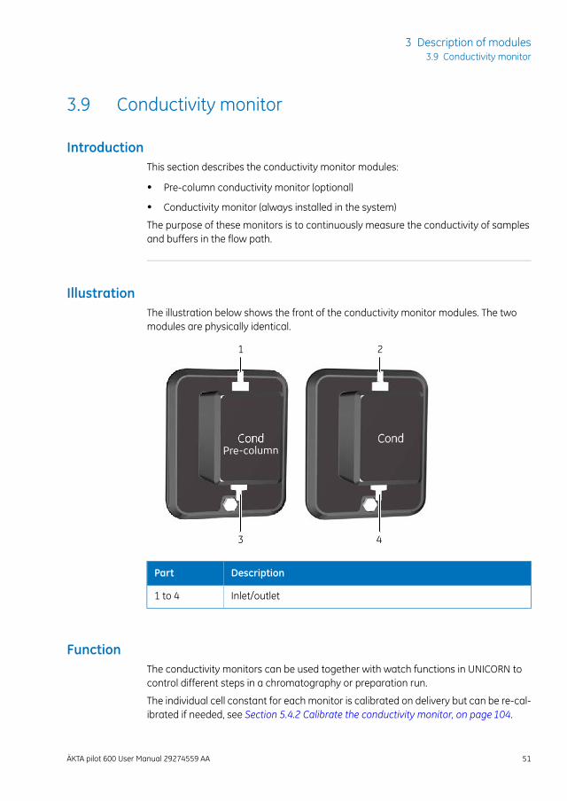
IllustrationThe illustration below shows the front of the conductivity monitor modules. The twomodules are physically identical.
Pre-column
1 2
3 4
DescriptionPart
Inlet/outlet1 to 4
FunctionThe conductivity monitors can be used together with watch functions in UNICORN tocontrol different steps in a chromatography or preparation run.
The individual cell constant for each monitor is calibrated on delivery but can be re-cal-ibrated if needed, see Section 5.4.2 Calibrate the conductivity monitor, on page 104.
ÄKTA pilot 600 User Manual 29274559 AA 51
3 Description of modules3.9 Conductivity monitor
As variation in temperature influences conductivity readings, the conductivity flow cellis fitted with a temperature sensor that measures the temperature of the eluent. Atemperature compensation factor is used to report the conductivity in relation to a setreference temperature. The measured temperature is also used for pH electrode com-pensation.
Pre-columnconductivitymonitorIf a conductivity monitor is installed in the flow path before the column valve, it can beused
• to follow conductivity during washing of pumps and valves before the column,
• to monitor that the sample feed has suitable conductivity for the chromatographyrun,
• to monitor that column equilibration is completed by comparing conductivity levelsbefore and after the column,
• to monitor that all sample has been wash out from the air trap by comparing con-ductivity of the sample and buffer used to finalize sample application (if using theair trap during sample application).
Conductivity monitor(post-column)
The conductivity monitor after the column can be used
• to measure the conductivity of salt gradients during gradient elution,
• to monitor washing of the system, with the column(s) by-passed,
• to monitor that column equilibration is completed by comparing conductivity levelswith column in-line and by-passed,
• to follow peak positions relative to conductivity.
52 ÄKTA pilot 600 User Manual 29274559 AA
3 Description of modules3.9 Conductivity monitor
3.10 UV monitor
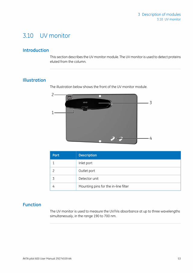
IntroductionThis section describes the UVmonitormodule. The UVmonitor is used to detect proteinseluted from the column.
IllustrationThe illustration below shows the front of the UV monitor module.
2
1
3
4
DescriptionPart
Inlet port1
Outlet port2
Detector unit3
Mounting pins for the in-line filter4
FunctionThe UV monitor is used to measure the UV/Vis absorbance at up to three wavelengthssimultaneously, in the range 190 to 700 nm.
ÄKTA pilot 600 User Manual 29274559 AA 53
3 Description of modules3.10 UV monitor
Pressure protectionThe UV monitor is sensitive to high pressure, but normally the pressure is low after thecolumn. To protect sensitive monitors after the column, the post-column pressure hasan alarm level of 0.8 MPa. This alarm is independent of other settings.
UV cell sizeThe UV flow cell is available in two sizes:
• 2 mm UV flow cell, can be used in all applications
• 5 mm UV flow cell, is recommended for peak volumes larger than 1000 mL
Turning off the lampThe UV lamp can be turned off manually if not needed during a run, for example duringcolumnor systemconditioningor equilibrationover long time, cleaning columnor system,or sanitization. It will be turned on automatically for the next run.
Follow the steps below to turn off the lamp:
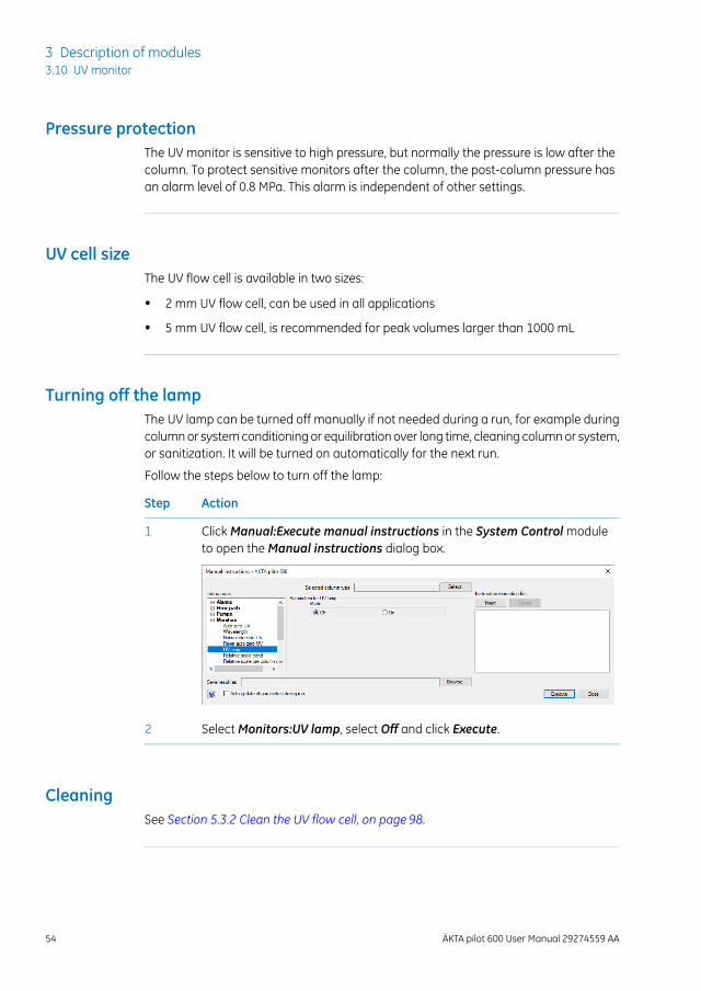
ActionStep
ClickManual:Execute manual instructions in the System Controlmoduleto open theManual instructions dialog box.
1
SelectMonitors:UV lamp, select Off and click Execute.2
CleaningSee Section 5.3.2 Clean the UV flow cell, on page 98.
54 ÄKTA pilot 600 User Manual 29274559 AA
3 Description of modules3.10 UV monitor
3.11 pH monitor (optional)
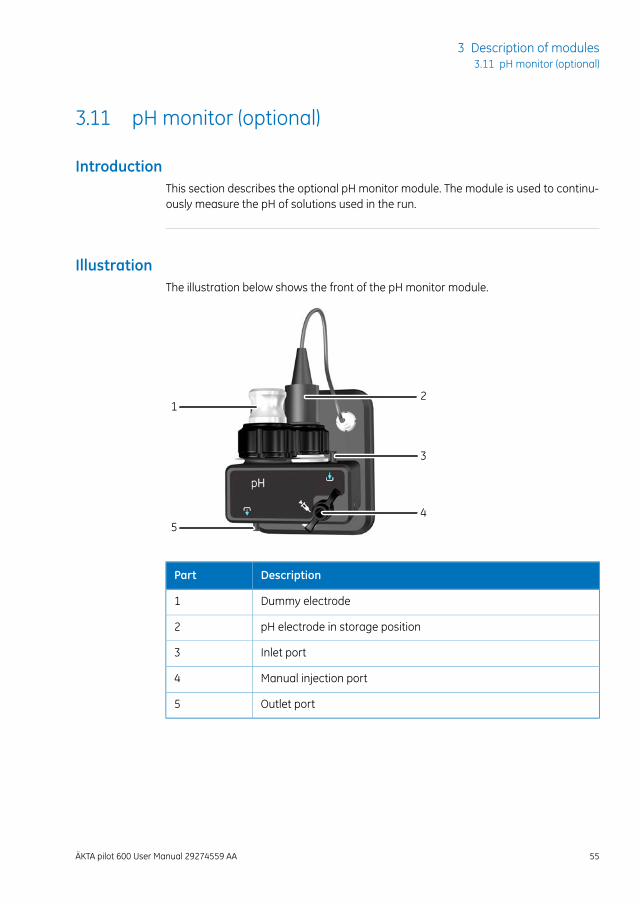
IntroductionThis section describes the optional pH monitor module. The module is used to continu-ously measure the pH of solutions used in the run.
IllustrationThe illustration below shows the front of the pH monitor module.
5
12
3
4
DescriptionPart
Dummy electrode1
pH electrode in storage position2
Inlet port3
Manual injection port4
Outlet port5
ÄKTA pilot 600 User Manual 29274559 AA 55
3 Description of modules3.11 pH monitor (optional)
FunctionThe pH module has two positions for the electrode: one position for measurements,calibration or cleaning in-line, and one for storage of the electrode. A dummy is placedin whichever position the electrode is not using. Themodule also has amanual injectionport that facilitates the pH calibration. The pH electrode can both be calibrated beforea run and cleaned after, without the need to open the flow path.
Pressure protectionThe pH electrode is sensitive to high pressure, but normally the pressure is low after thecolumn. To protect sensitive monitors after the column, the post-column pressure hasan alarm level of 0.8 MPa. This alarm is independent of other settings.
Cleaning, storing, andcalibrationFor instructions on how to clean the pHelectrode outside the flowpath, store or calibratethe pH monitor, see the ÄKTA pilot 600 Operating Instructions.
Before running a cleaning-in-place (CIP) method to clean the pH electrode in the flowpath, make sure the electrode is compatible with the selected cleaning solution.
Perform a system wash after the calibration to wash away the calibrationbuffer that was introduced into the flow path.
Tip:
56 ÄKTA pilot 600 User Manual 29274559 AA
3 Description of modules3.11 pH monitor (optional)
3.12 Outlet valves
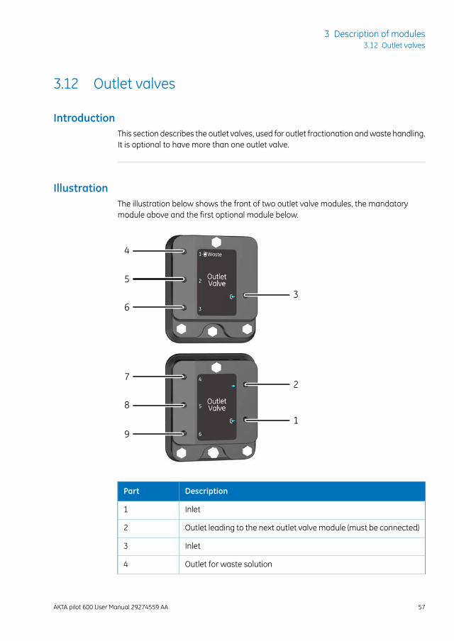
IntroductionThis section describes the outlet valves, used for outlet fractionation andwaste handling.It is optional to have more than one outlet valve.
IllustrationThe illustration below shows the front of two outlet valve modules, the mandatorymodule above and the first optional module below.
1
2
3
4
5
6
7
8
9
DescriptionPart
Inlet1
Outlet leading to the next outlet valve module (must be connected)2
Inlet3
Outlet for waste solution4
ÄKTA pilot 600 User Manual 29274559 AA 57
3 Description of modules3.12 Outlet valves
DescriptionPart
Outlets for fractionation5 to 9
FunctionThe outlet valvemodule contains a number ofmembrane valves to control the flow pathduring fractionation. Formore information about fractionation, see Section 4.2 Fraction-ation, on page 71. The first outlet port denoted 1-Waste is used as waste outlet in allpre-defined methods.
Up to five outlet valves can be installed in the system, giving up to 15 outlets.
If additional outlet valvemodules are installed, the outlets that lead to the nextmodule must be connected to the inlet of next module inlet. Keep the tubingbetween the outlet valve modules as short as possible. For more information,see separate installation instructions for the outlet valve module.
Note:
Outlet tubingThe outlets are connectedwith SNAP connectors to outlet tubingwith an inner diameterof 3.2 mm.
When running at low flow rates or collecting small fractions, it is recommended to usean adapter to be able to use outlet tubingwith smaller diameter. If even smaller diameteris required, use suitable nipple and ferrule to further reduce the diameter.
Reduced tubing diameter increases the system pressure.Note:
58 ÄKTA pilot 600 User Manual 29274559 AA
3 Description of modules3.12 Outlet valves

4 Operation
About this chapterBasic instructions on how to prepare and perform a run are given in the ÄKTA pilot 600Operating Instructions. This chapter considers additional topics related to operation ofthe instrument.
In this chapterThis chapter contains the following sections:
See pageSection
604.1 Sample application
714.2 Fractionation
774.3 Intelligent packing
814.4 Dual pump flow
844.5 Pressure control
874.6 Performing runs in a cold environment
ÄKTA pilot 600 User Manual 29274559 AA 59
4 Operation
4.1 Sample application
About this sectionA basic description of how to apply a sample to the column in a ÄKTA pilot 600 systemis given in ÄKTA pilot 600 Operating Instructions. This section gives more in-depth infor-mation on sample application techniques.
In this sectionThis section contains the following subsections:
See pageSection
614.1.1 Background considerations
634.1.2 Apply sample from a system inlet
684.1.3 Apply sample from a Superloop
60 ÄKTA pilot 600 User Manual 29274559 AA
4 Operation4.1 Sample application
4.1.1 Background considerations
Chromatography techniquesDifferent chromatography techniques make different demands on sample application,as summarized in the table below. These considerations can influence the choice ofsample application technique.
More information about chromatography techniques may be found in the Life ScienceHandbooks, available for download from the Support pages onwww.gelifesciences.com.
DemandsTechnique
A sharply defined sample band with constant sampleconcentration throughout. Any broadeningof the samplebandwill be reflected in broadening of the elution peaks.
Size exclusion chro-matography (SEC)
The sample volume applied to the column should ideallynot be more than 10% of the column volume. Preciserequirements will depend on the separation being per-formed.
Sample is concentrated by adsorption on to the chro-matography resin during sample application. The volumeand concentration of sample is not critical, provided thatthe capacity of the column is not exceeded.
Adsorptionchromatogra-phy, (e.g., affinity or ionexchangechromatogra-phy)
Sample application optionsSamples may be applied to the column from a system inlet (A inlet) or from a Superloop150 SNAP mounted on the column valve.
DescriptionWhen?Option
The sample is pumped onto thecolumn from one of the A inletsusing system pump A. The samplepasses through the system pump,flow restrictor and any othermod-ules before the column valve in theflow path.
Recommended for sam-ple volumes larger than50 mL and for columnperformance testswheresample is readily avail-able.
Apply sample froma system inlet
The sample volume that can beapplied from a system inlet is inprinciple unlimited.
ÄKTA pilot 600 User Manual 29274559 AA 61
4 Operation4.1 Sample application
4.1.1 Background considerations
DescriptionWhen?Option
A Superloop (sold separately) ismanually filled with sample andconnected to one of the two col-umnpositions. The sample is inject-ed onto the column by directingthe system flow via the Superloop,and does not pass through anyother modules in the system.
Recommended for sam-ple volumes in the range10 to 150 mL.
Apply sample froma Superloop
Sample volumes applied from aSuperloop are limited to the vol-ume of the Superloop (150 mL).
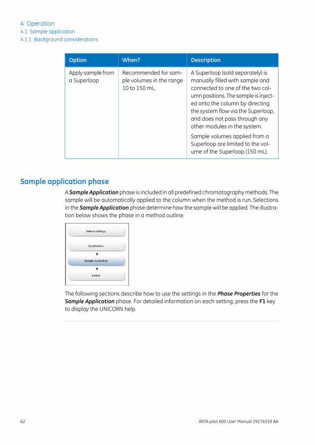
Sample application phaseA Sample Applicationphase is included in all predefined chromatographymethods. Thesample will be automatically applied to the column when the method is run. Selectionsin the Sample Application phase determine how the samplewill be applied. The illustra-tion below shows the phase in a method outline.
The following sections describe how to use the settings in the Phase Properties for theSample Application phase. For detailed information on each setting, press the F1 keyto display the UNICORN help.
62 ÄKTA pilot 600 User Manual 29274559 AA
4 Operation4.1 Sample application4.1.1 Background considerations
4.1.2 Apply sample from a system inlet
IntroductionSamples may be applied from a system inlet using the system pump A. Up to three Inletvalve Amodules are supported, giving up to nine inlets, labeled A1 to A9. Inlet A1 isnormally used for buffer: other inlets may be used for sample or different buffers as re-quired.
Sample application from B inlets is not recommended.Note:
There are up to three stages in sample application from a sample inlet.
DescriptionStage
Prime the inlet tubing with sample. This will fill the inlet tubing up to the inletvalve with sample, giving more precise control over the amount of sampleapplied to the column.
1
The inlet tubingmay be primed automatically (see Sample Application phaseproperties, on page 63) or manually (see Priming the inlet tubing manually,on page 66).
Apply the sample according to the phase properties in the Sample Applica-tion phase.
2
Finalize the sample application (if selected in the Sample Applicationphase).This will chase the sample remaining in the flowpath on to the column, usingthe buffer inlet as specified inMethod Settings.
3
When to useSample application froma system inlet is recommended for sample volumes larger than50 mL.
Sample Application phaseproperties
To apply sample from a system inlet, select Inject sample directly onto column in thePhase Properties for the Sample Application phase. Set the parameters as describedin the table below. For details of settings in the Phase Properties that are not describedhere, see the UNICORN online help.
ÄKTA pilot 600 User Manual 29274559 AA 63
4 Operation4.1 Sample application
4.1.2 Apply sample from a system inlet
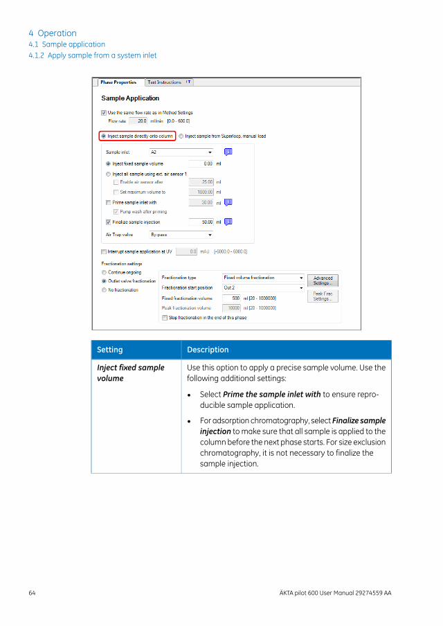
DescriptionSetting
Use this option to apply a precise sample volume. Use thefollowing additional settings:
Inject fixed samplevolume
• Select Prime the sample inlet with to ensure repro-ducible sample application.
• For adsorption chromatography, select Finalize sampleinjection to make sure that all sample is applied to thecolumnbefore the next phase starts. For size exclusionchromatography, it is not necessary to finalize thesample injection.
64 ÄKTA pilot 600 User Manual 29274559 AA
4 Operation4.1 Sample application4.1.2 Apply sample from a system inlet
DescriptionSetting
Use this option to apply all available sample. Sample appli-cation will stop when the External air sensor 1 detects airin the sample inlet tubing. See Section 3.1 External air sen-sors (optional), on page 30 for more information about ex-ternal air sensors.
Note:
The option in Phase Properties only supports External airsensor 1. Additional air sensors can be supported by editingthe text instruction in the Sample Application phase.
Inject all sample usingext. air sensor 1
When this option is selected, the following options areavailable
• Enable air sensor after enables the air sensor whenthe specified volumehas beenpumped. Use this optionif the sample inlet tubing has not been primed withsample or buffer and may contain air. Enter a volumelarger than the volume of the inlet tubing.
• Set maximum volume to sets a maximum limit on theamount of sample applied.
This option fills the inlet tubing with sample by pumpingthe specified volume of sample. Enter a volume larger thanthe volume of the inlet tubing.
Prime sample inletwith
When this option is selected, select Pump wash afterpriming. Thiswill flush the flowpath up to the column valvewith buffer.
Note:
The flowpath can be primedmanually if desired, see Primingthe inlet tubing manually, on page 66.
This option pumps the specified volume of buffer directlyafter the sample. Buffer is taken from the buffer inletspecified inMethod Settings. The recommended volumeis 5 to 10 times larger than the flow path volume up to thecolumn valve. If the Air Trap valve is set to In-line, theminimum recommended volume is 300 mL.
Finalize sample injec-tion
Set the air trap valve to In-line if there is a risk that air mayenter the inlet tubing. This applies, for example, if the inlettubing has not been primed, or if an external air sensorclose to the inlet valve port is used tominimize sample loss.
Air trap valve
ÄKTA pilot 600 User Manual 29274559 AA 65
4 Operation4.1 Sample application
4.1.2 Apply sample from a system inlet
DescriptionSetting
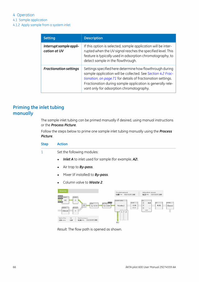
If this option is selected, sample application will be inter-ruptedwhen the UV signal reaches the specified level. Thisfeature is typically used in adsorption chromatography, todetect sample in the flowthrough.
Interruptsampleappli-cation at UV
Settings specified here determine how flowthrough duringsample application will be collected. See Section 4.2 Frac-tionation, on page 71 for details of fractionation settings.Fractionation during sample application is generally rele-vant only for adsorption chromatography.
Fractionation settings
Priming the inlet tubingmanually
The sample inlet tubing can be primed manually if desired, using manual instructionsor the Process Picture.
Follow the steps below to prime one sample inlet tubing manually using the ProcessPicture.
ActionStep
Set the following modules:1
• Inlet A to inlet used for sample (for example, A2).
• Air trap to By-pass.
• Mixer (if installed) to By-pass.
• Column valve toWaste 2.
Result: The flow path is opened as shown.
66 ÄKTA pilot 600 User Manual 29274559 AA
4 Operation4.1 Sample application4.1.2 Apply sample from a system inlet
ActionStep
Insert the end of the sample inlet tubing into the sample container.
Tip:
If the tubing is filled with buffer, introduce a small air bubble into the sampletubing between the buffer and the sample. This will mark the progress of thesample front along the flow path tubing.
2
Set a suitable pump flow rate, for example 100 mL/min. Follow the samplefront in the tubing. (The sample front may be difficult to follow if the flowrate is too high.)
3
When the sample front has passed through the inlet valve, click Pause .4
Switch the inlet valve to buffer inlet.5
Click Continue , change the flow rate to maximum (600 mL/min), andwait until all air bubbles have been removed through theWaste 2 outlet onthe column valve.
6
Result: The flow path contains sample up to the inlet valve and buffer fromthe inlet valve to the column valve.
Click End .7
ÄKTA pilot 600 User Manual 29274559 AA 67
4 Operation4.1 Sample application
4.1.2 Apply sample from a system inlet
4.1.3 Apply sample from a Superloop
IntroductionSamplesmaybeapplied to the column fromaSuperloop, connected to the columnvalvedirectly before the column. Superloop 150 SNAP (capacity 150 mL) is fitted with SNAPconnections.
Instructions for handling the Superloop, including filling with sample and cleaning, aregiven in the Superloop 150 SNAP Instructions, supplied with the Superloop.
CAUTIONDo not use a Superloopwithout its protective jacket. The Superloopmay crack if exposed to overpressure.
When to useUse of a Superloop is recommended for:
• sample volumes in the range 10 to 150 mL
• Size exclusion chromatography and desalting (to minimize band broadening)
Sample application froma Superloop can only be usedwith downflow throughthe column.
Note:
Mounting the SuperloopThe Superloop should be mounted close to the column valve to keep connecting tubingshort. Mounting in an ÄKTA accessory holder on a module front panel with rails (seeModule front panel with rails, on page25) or an Extension Stand (see Extension stand forcolumns and accessories, on page 24) is recommended.
Follow the steps below to mount and connect the Superloop.
ActionStep
Fill the Superloop eluent chamber with buffer and sample chamber withsample (see the separate Superloop 150 SNAP Instructions)
1
Mount the Superloop on or close to the ÄKTA pilot 600 instrument, with thesample chamber downwards.
2
Connect the Superloop eluent inlet (top connection) using SNAP connectorsto the top port for the unused column position on the column valve.
3
68 ÄKTA pilot 600 User Manual 29274559 AA
4 Operation4.1 Sample application4.1.3 Apply sample from a Superloop
ActionStep
Connect the Superloop sample outlet (bottom connection) using SNAP con-nectors to the bottom port for the unused column position on the columnvalve.
4
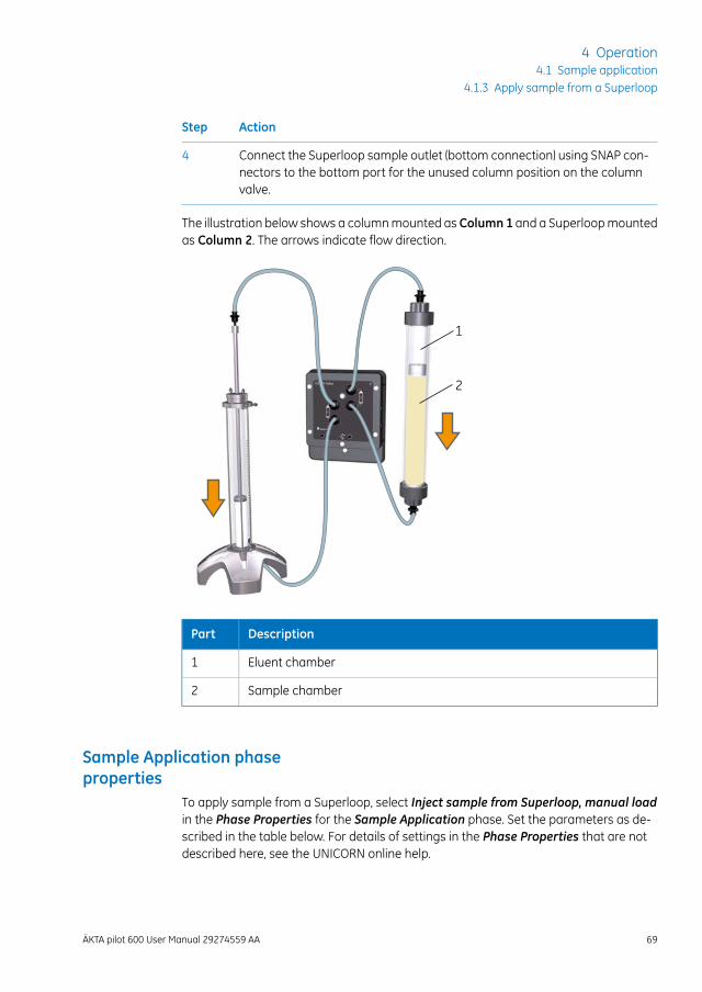
The illustration below shows a columnmounted as Column 1 and a Superloopmountedas Column 2. The arrows indicate flow direction.
1
2
DescriptionPart
Eluent chamber1
Sample chamber2
Sample Application phaseproperties
To apply sample from a Superloop, select Inject sample from Superloop, manual loadin the Phase Properties for the Sample Application phase. Set the parameters as de-scribed in the table below. For details of settings in the Phase Properties that are notdescribed here, see the UNICORN online help.
ÄKTA pilot 600 User Manual 29274559 AA 69
4 Operation4.1 Sample application
4.1.3 Apply sample from a Superloop
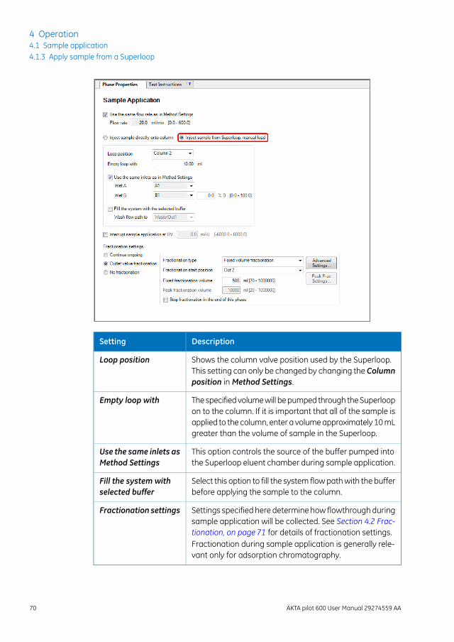
DescriptionSetting
Shows the column valve position used by the Superloop.This setting can only be changed by changing the Columnposition inMethod Settings.
Loop position
The specified volumewill bepumped through theSuperloopon to the column. If it is important that all of the sample isapplied to the column, enter a volumeapproximately 10mLgreater than the volume of sample in the Superloop.
Empty loop with
This option controls the source of the buffer pumped intothe Superloop eluent chamber during sample application.
Use the same inlets asMethod Settings
Select this option to fill the system flowpathwith the bufferbefore applying the sample to the column.
Fill the system withselected buffer
Settings specified here determine how flowthrough duringsample application will be collected. See Section 4.2 Frac-tionation, on page 71 for details of fractionation settings.Fractionation during sample application is generally rele-vant only for adsorption chromatography.
Fractionation settings
70 ÄKTA pilot 600 User Manual 29274559 AA
4 Operation4.1 Sample application4.1.3 Apply sample from a Superloop
4.2 Fractionation
IntroductionFractionation in ÄKTA pilot 600 system is performed using the outlet valves. Up to fiveoutlet valves can be installed in the system, giving up to 15 outlets. Outlet 1-Waste isused by default as a waste outlet.
Fractionation is set in the Phase Properties of the UNICORN method, and can be usedin the following phases:
• ColumnWash
• Sample Application
• Conditional Fractionation
• Elution
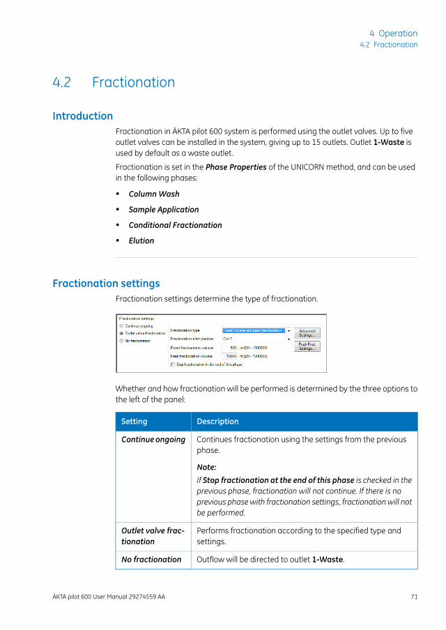
Fractionation settingsFractionation settings determine the type of fractionation.
Whether and how fractionation will be performed is determined by the three options tothe left of the panel:
DescriptionSetting
Continues fractionation using the settings from the previousphase.
Note:
If Stop fractionation at the end of this phase is checked in theprevious phase, fractionation will not continue. If there is noprevious phasewith fractionation settings, fractionationwill notbe performed.
Continue ongoing
Performs fractionation according to the specified type andsettings.
Outlet valve frac-tionation
Outflow will be directed to outlet 1-Waste.No fractionation
ÄKTA pilot 600 User Manual 29274559 AA 71
4 Operation4.2 Fractionation
The remaining settings apply to Outlet valve fractionation:
DescriptionSetting
Choose the fractionation type. See below for details.Fractionation type
Choose the outlet position for the first fraction. Subsequentfractionswill be directed to the next outlet position in numericalorder. Outflow after the last outlet position (determined by thesettings in Advanced Settings) will be directed to outlet 1-Waste.
Fractionationstart position
Applies to fractionation typeswith fixed volume fractions. Enterthe fraction volume.
Fixed fractiona-tion volume
Applies to fractionation types with peak fractionation. Specifythe peak detection conditions in Peak Frac Settings. If the col-lected volume for one fraction reaches the value set in Peakfractionation volume, outflow will be directed to the nextfraction. Set a large value for this parameter to avoid splittingpeaks into several fractions.
Peak fractionationvolume
Fractionationwill stop at the end of the phase, even if fraction-ation in the next phase is set to Continue ongoing.
Note:
This setting is not available inConditional Fractionationphases.
Stop fractionationat the end of thisphase
Fractionation typesThe following fractionation types can be used for Outlet valve fractionation:
DescriptionFractionationtype
Fixed volume fractions will be collected.Fixedvolume frac-tionation
Fractions will be collected according to the peak detectionconditions in Peak Frac Settings. When no peak is detected,flow is directed to Outlet 1-Waste.
Peak fractionation
Combines fixed volume and peak fractionation.Fixed volume andpeak fractiona-tion
Fixed volume fractionation applies as long as a peak is not de-tected. Peaks are collected as separate fractions according tothe peak detection conditions in Peak Frac Settings.
72 ÄKTA pilot 600 User Manual 29274559 AA
4 Operation4.2 Fractionation
DescriptionFractionationtype
Outflow will be directed to the specified outlet position untilfractionation ends.
Note:
Make sure that Stop fractionation at the end of this phase ischecked in the current or a subsequent phase as appropriate,to avoid directing all subsequent outflow to the specified outletposition.
Fixed outlet
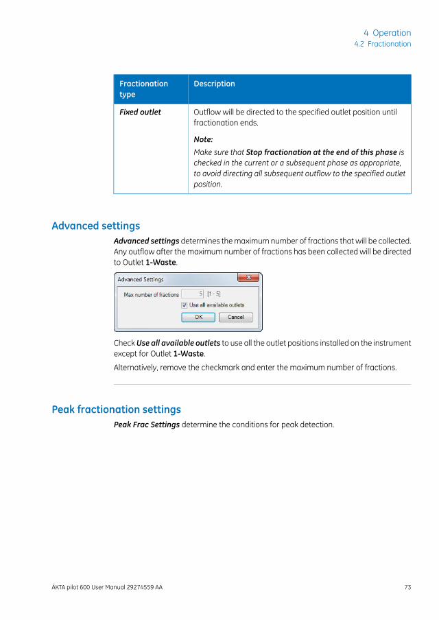
Advanced settingsAdvanced settings determines themaximumnumber of fractions that will be collected.Any outflow after the maximum number of fractions has been collected will be directedto Outlet 1-Waste.
CheckUse all available outlets to use all the outlet positions installed on the instrumentexcept for Outlet 1-Waste.
Alternatively, remove the checkmark and enter the maximum number of fractions.
Peak fractionation settingsPeak Frac Settings determine the conditions for peak detection.
ÄKTA pilot 600 User Manual 29274559 AA 73
4 Operation4.2 Fractionation
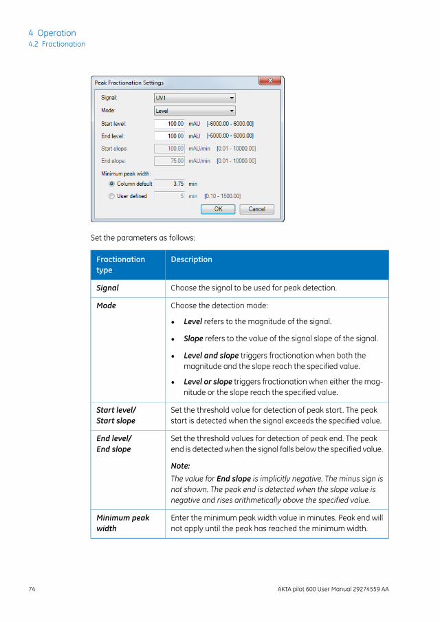
Set the parameters as follows:
DescriptionFractionationtype
Choose the signal to be used for peak detection.Signal
Choose the detection mode:Mode
• Level refers to the magnitude of the signal.
• Slope refers to the value of the signal slope of the signal.
• Level and slope triggers fractionation when both themagnitude and the slope reach the specified value.
• Level or slope triggers fractionation when either the mag-nitude or the slope reach the specified value.
Set the threshold value for detection of peak start. The peakstart is detected when the signal exceeds the specified value.
Start level/Start slope
Set the threshold values for detection of peak end. The peakend is detectedwhen the signal falls below the specified value.
Note:
The value for End slope is implicitly negative. The minus sign isnot shown. The peak end is detected when the slope value isnegative and rises arithmetically above the specified value.
End level/End slope
Enter the minimum peak width value in minutes. Peak end willnot apply until the peak has reached the minimum width.
Minimum peakwidth
74 ÄKTA pilot 600 User Manual 29274559 AA
4 Operation4.2 Fractionation
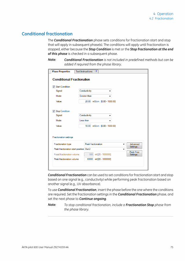
Conditional fractionationThe Conditional Fractionation phase sets conditions for fractionation start and stopthat will apply in subsequent phase(s). The conditions will apply until fractionation isstopped, either because the Stop Condition is met or the Stop fractionation at the endof this phase is checked in a subsequent phase.
Conditional Fractionation is not included in predefined methods but can beadded if required from the phase library.
Note:
Conditional Fractionation can be used to set conditions for fractionation start and stopbased on one signal (e.g., conductivity) while performing peak fractionation based onanother signal (e.g., UV absorbance).
To use Conditional Fractionation, insert the phase before the onewhere the conditionsare required. Set the fractionation settings in the Conditional Fractionation phase, andset the next phase to Continue ongoing.
To stop conditional fractionation, include a Fractionation Stop phase fromthe phase library.
Note:
ÄKTA pilot 600 User Manual 29274559 AA 75
4 Operation4.2 Fractionation
Fractionation in practiceWhen fractionation is complete or if you re-use outlet positions, empty the outlet tubingby releasing the SNAP connectors on the outlets and allowing the tubing contents todrain into the fraction containers.
For unattended fractionation, the maximum number of fractions that can be collectedis 14 (using five installed outlet valves). Plan your fractionation settings carefully to avoidcreating more than the maximum number of fractions. Use Conditional Fractionationand Peak fractionation to optimize the number of fractions.
If the number of fractions exceeds the number of available outlets, it is possible to re-use outlet positions for fractionation in different phases (for example, set Fractionationstart position toOut 2 in all phases that use fractionation). This requires that you changethe outlet tubing and fraction containers on re-used positions between phases. It maybe advisable include aMiscellaneous phase to set a Pause timer with a message, toremind you to change the containers.
76 ÄKTA pilot 600 User Manual 29274559 AA
4 Operation4.2 Fractionation
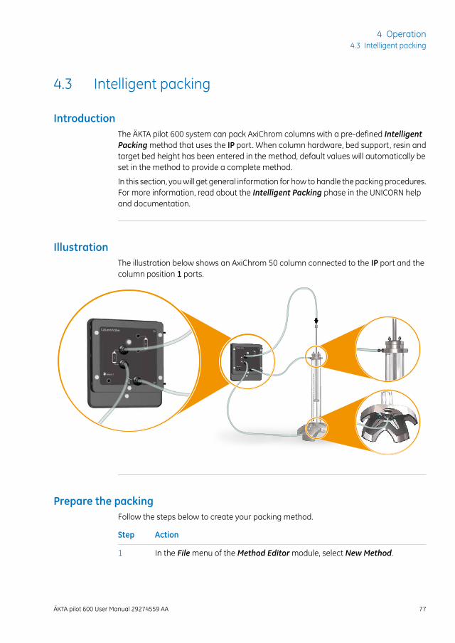
4.3 Intelligent packing
IntroductionThe ÄKTA pilot 600 system can pack AxiChrom columns with a pre-defined IntelligentPackingmethod that uses the IP port. When column hardware, bed support, resin andtarget bed height has been entered in the method, default values will automatically beset in the method to provide a complete method.
In this section, youwill get general information for how to handle the packing procedures.For more information, read about the Intelligent Packing phase in the UNICORN helpand documentation.
IllustrationThe illustration below shows an AxiChrom 50 column connected to the IP port and thecolumn position 1 ports.
Prepare the packingFollow the steps below to create your packing method.
ActionStep
In the Filemenu of theMethod Editormodule, select New Method.1
ÄKTA pilot 600 User Manual 29274559 AA 77
4 Operation4.3 Intelligent packing
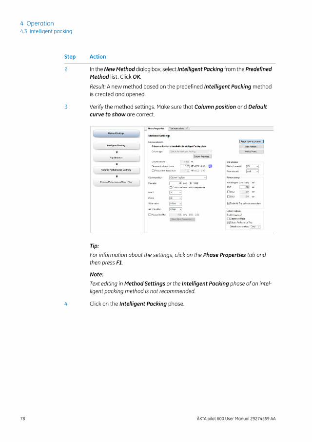
ActionStep
In theNewMethoddialogbox, select Intelligent Packing from thePredefinedMethod list. Click OK.
2
Result: A newmethod based on the predefined Intelligent Packingmethodis created and opened.
Verify the method settings. Make sure that Column position and Defaultcurve to show are correct.
3
Tip:
For information about the settings, click on the Phase Properties tab andthen press F1.
Note:
Text editing inMethod Settings or the Intelligent Packing phase of an intel-ligent packing method is not recommended.
Click on the Intelligent Packing phase.4
78 ÄKTA pilot 600 User Manual 29274559 AA
4 Operation4.3 Intelligent packing
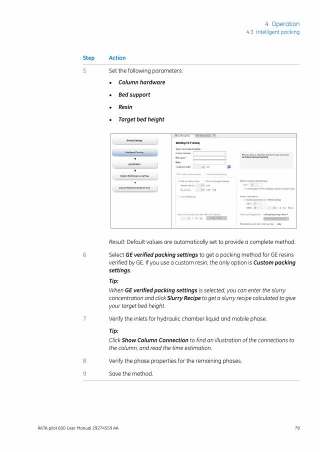
ActionStep
Set the following parameters:5
• Column hardware
• Bed support
• Resin
• Target bed height
Result: Default values are automatically set to provide a complete method.
Select GE verified packing settings to get a packing method for GE resinsverified by GE. If you use a custom resin, the only option is Custom packingsettings.
Tip:
When GE verified packing settings is selected, you can enter the slurryconcentration and click Slurry Recipe to get a slurry recipe calculated to giveyour target bed height.
6
Verify the inlets for hydraulic chamber liquid and mobile phase.
Tip:
Click Show Column Connection to find an illustration of the connections tothe column, and read the time estimation.
7
Verify the phase properties for the remaining phases.8
Save the method.9
ÄKTA pilot 600 User Manual 29274559 AA 79
4 Operation4.3 Intelligent packing
Perform the packingFollow the steps below to perform the packing. Use theUNICORNmethod created above.
ActionStep
Connect position 1 or 2 according to the method on the Column valvemodule to the top (on the adaptor) and bottom of the AxiChrom column.Connect the IP port to the horizontal nipple on the column top (not on theadaptor). See Illustration, on page 77. Note that the illustration shows con-nections to position 1.
1
WARNINGBefore connecting a column, read the instructions foruse of the column.
Tip:
In the Intelligent Packing phase of your packing method, click on ShowColumn Connection to find an illustration of the connections.
Run your packingmethod in the SystemControlmodule, follow the instruc-tions in dialog boxes on the screen.
Note:
Make sure that you pressContinuewhen the adaptermeets the consolidatedbed surface. If Continue is not pressed in time, the resin can be damaged,and the delta column pressure alarm pauses the packing method.
2
Evaluate and save the packing of the column in the Evaluationmodule, seethe Getting started page in the Evaluationmodule, or the UNICORN Evalu-ation Manual.
3
80 ÄKTA pilot 600 User Manual 29274559 AA
4 Operation4.3 Intelligent packing
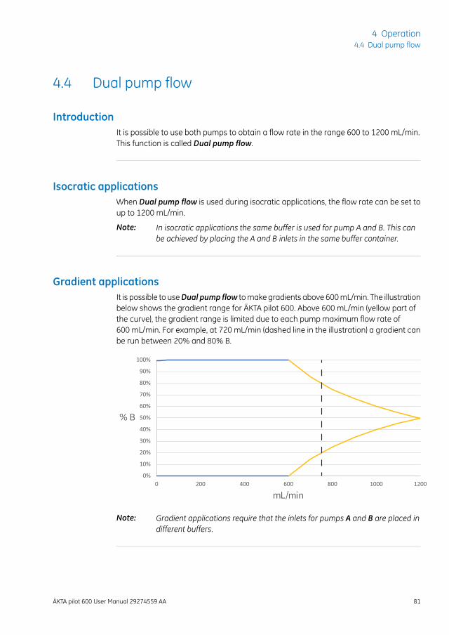
4.4 Dual pump flow
IntroductionIt is possible to use both pumps to obtain a flow rate in the range 600 to 1200 mL/min.This function is called Dual pump flow.
Isocratic applicationsWhen Dual pump flow is used during isocratic applications, the flow rate can be set toup to 1200 mL/min.
In isocratic applications the same buffer is used for pump A and B. This canbe achieved by placing the A and B inlets in the same buffer container.
Note:
Gradient applicationsIt is possible to useDual pump flow tomake gradients above 600mL/min. The illustrationbelow shows the gradient range for ÄKTA pilot 600. Above 600 mL/min (yellow part ofthe curve), the gradient range is limited due to each pump maximum flow rate of600 mL/min. For example, at 720 mL/min (dashed line in the illustration) a gradient canbe run between 20% and 80% B.
0%
10%
20%
30%
40%
50%
60%
70%
80%
90%
100%
0 200 400 600 800 1000 1200
% B
mL/min
Gradient applications require that the inlets for pumps A and B are placed indifferent buffers.
Note:
ÄKTA pilot 600 User Manual 29274559 AA 81
4 Operation4.4 Dual pump flow
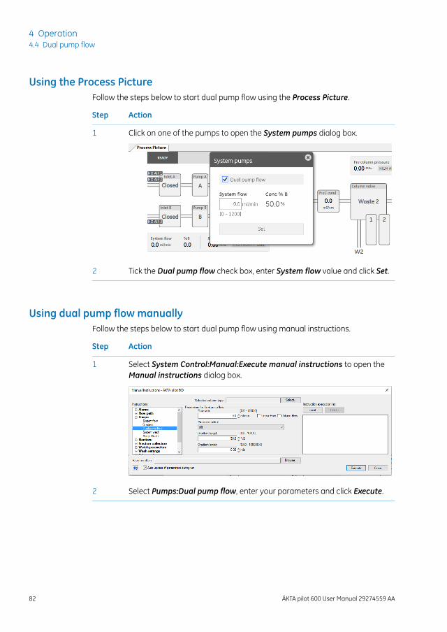
Using the Process PictureFollow the steps below to start dual pump flow using the Process Picture.
ActionStep
Click on one of the pumps to open the System pumps dialog box.1
Tick the Dual pump flow check box, enter System flow value and click Set.2
Using dual pump flow manuallyFollow the steps below to start dual pump flow using manual instructions.
ActionStep
Select System Control:Manual:Execute manual instructions to open theManual instructions dialog box.
1
Select Pumps:Dual pump flow, enter your parameters and click Execute.2
82 ÄKTA pilot 600 User Manual 29274559 AA
4 Operation4.4 Dual pump flow
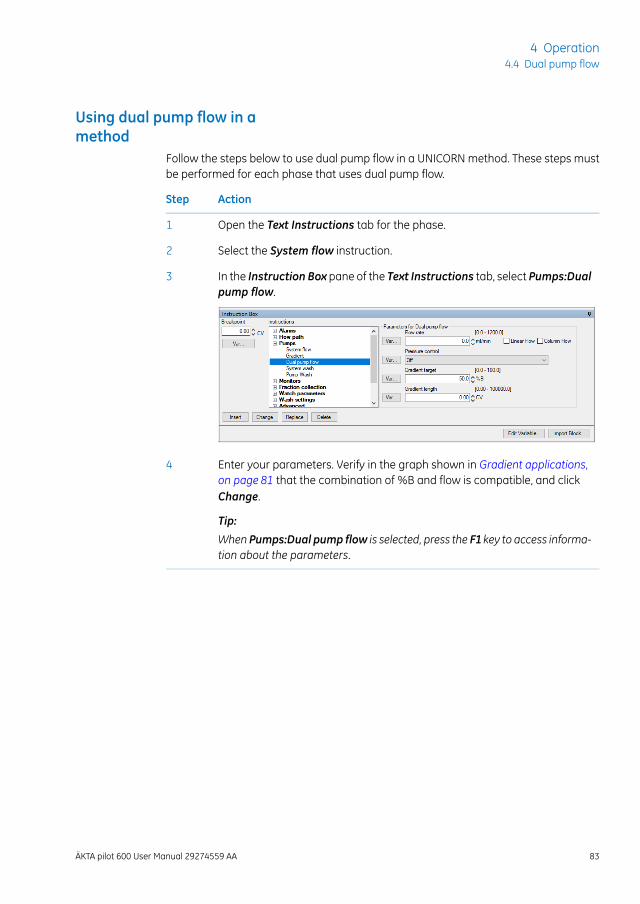
Using dual pump flow in amethod
Follow the steps below to use dual pump flow in a UNICORN method. These steps mustbe performed for each phase that uses dual pump flow.
ActionStep
Open the Text Instructions tab for the phase.1
Select the System flow instruction.2
In the Instruction Box pane of the Text Instructions tab, select Pumps:Dualpump flow.
3
Enter your parameters. Verify in the graph shown in Gradient applications,on page 81 that the combination of %B and flow is compatible, and clickChange.
Tip:
When Pumps:Dual pump flow is selected, press the F1 key to access informa-tion about the parameters.
4
ÄKTA pilot 600 User Manual 29274559 AA 83
4 Operation4.4 Dual pump flow
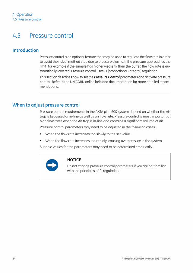
4.5 Pressure control
IntroductionPressure control is an optional feature thatmay be used to regulate the flow rate in orderto avoid the risk of method stop due to pressure alarms. If the pressure approaches thelimit, for example if the sample has higher viscosity than the buffer, the flow rate is au-tomatically lowered. Pressure control uses PI (proportional-integral) regulation.
This section describes how to set the Pressure Control parameters and activate pressurecontrol. Refer to the UNICORN online help and documentation for more detailed recom-mendations.
When to adjust pressure controlPressure control requirements in the ÄKTA pilot 600 system depend on whether the Airtrap is bypassed or in-line as well as on flow rate. Pressure control is most important athigh flow rates when the Air trap is in-line and contains a significant volume of air.
Pressure control parameters may need to be adjusted in the following cases:
• When the flow rate increases too slowly to the set value.
• When the flow rate increases too rapidly, causing overpressure in the system.
Suitable values for the parameters may need to be determined empirically.
NOTICEDo not change pressure control parameters if you are not familiarwith the principles of PI regulation.
84 ÄKTA pilot 600 User Manual 29274559 AA
4 Operation4.5 Pressure control
Optimize pressure controlsettings
To optimize pressure control parameters, change the settings manually and test thenew settings with a manual run. Follow the steps below:
ActionStep
Open theAdvanced:Pressure control parameters sectionofManual instruc-tions in System Control.
1
Adjust the parameters as required.2
Activate pressure control and select the appropriate Pressure control pa-rameter in the Pumps:System Flow section ofManual instructions.
3
Run Pumps:System flow at a suitable flow rate to test the effect of youradjustments.
4
When you are satisfied, update the pressure control parameters in SystemSettings so that the optimized settingswill apply automatically in the future.
5
Set pressure control parametersFollow the steps below to change the pressure control parameters in System:Settings.Settings changed in this way will apply as default for both manual and method runs.
ActionStep
Open System:Settings in the UNICORN System Controlmodule.1
ÄKTA pilot 600 User Manual 29274559 AA 85
4 Operation4.5 Pressure control
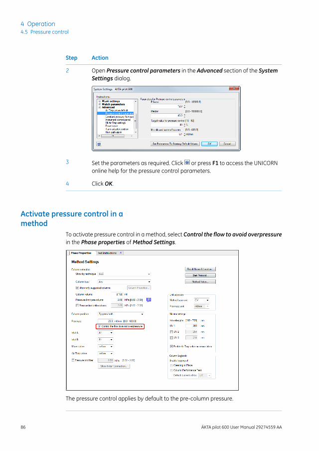
ActionStep
Open Pressure control parameters in the Advanced section of the SystemSettings dialog.
2
Set the parameters as required. Click or press F1 to access the UNICORNonline help for the pressure control parameters.
3
Click OK.4
Activate pressure control in amethod
To activate pressure control in amethod, select Control the flow to avoid overpressurein the Phase properties ofMethod Settings.
The pressure control applies by default to the pre-column pressure.
86 ÄKTA pilot 600 User Manual 29274559 AA
4 Operation4.5 Pressure control
4.6 Performing runs in a cold environment
IntroductionThe instrument can be placed and run in a cold cabinet or room. When running the in-strument in a cold environment, take the precautions listed in this section.
Precautions concerning runs ina cold cabinet
NOTICE
• Avoid condensation. If ÄKTA pilot 600 is kept in a cold room,cold cabinet or similar, keep it switched on in order to avoidcondensation.
• Avoid overheating. If ÄKTA pilot 600 is kept in a cold cabinetand the cold cabinet is switched off, also switch offÄKTA pilot 600 and keep the cold cabinet open to avoid over-heating.
• Place the computer in roomtemperature. If theÄKTApilot 600instrument is placed in a cold room, use a cold room compat-ible computer or place the computer outside the cold roomand use the Ethernet cable delivered with the instrument toconnect to the computer.
Configure at room temperatureConfigure the modules at room temperature, to prevent leaks in the system and kinkson the tubing.
Moving to/from a coldenvironment
Reset the pressure sensors, see Section 5.4.1 Reset the pressure sensors, on page 101,and calibrate the pH electrode, see the ÄKTA pilot 600 Operating Instructions, when theinstrument has equilibrated to the new temperature.
ÄKTA pilot 600 User Manual 29274559 AA 87
4 Operation4.6 Performing runs in a cold environment
Use equilibrated solutionsAlways use solutions equilibrated to the ambient temperature, for example, sample so-lutions, buffers, and standard buffers for pH calibration. Temperature differences mightfor example increase outgassing.
Higher viscosityGenerally, cold solutions have higher viscosity than warm solutions. The flow ratemightneed to be lowered to keep an acceptable back pressure.
88 ÄKTA pilot 600 User Manual 29274559 AA
4 Operation4.6 Performing runs in a cold environment
5 Maintenance
About this chapterRegular maintenance of the ÄKTA pilot 600 system is essential for reliable function.
This chapter describes the recommendedmaintenance schedules and provides detailedinstructions for maintenance operations.
In this chapterThis chapter contains the following sections:
See pageSection
925.1 Maintenance manager
935.2 Maintenance schedule
955.3 Cleaning procedures
1005.4 Calibration procedures
1095.5 Replacement procedures
Maintenance tasksRefer to theÄKTApilot 600Operating Instructions for instructions concerning the followingmaintenance tasks:
• Cleaning the instrument
• Cleaning the flow path
• Cleaning and storing the pH electrode
• Changing the pump rinsing solution
• Replacing the pump rinsing tubing
• Replacing flow path tubing and connectors
• Replacing valve membranes
• Replacing the main fuses
ÄKTA pilot 600 User Manual 29274559 AA 89
5 Maintenance
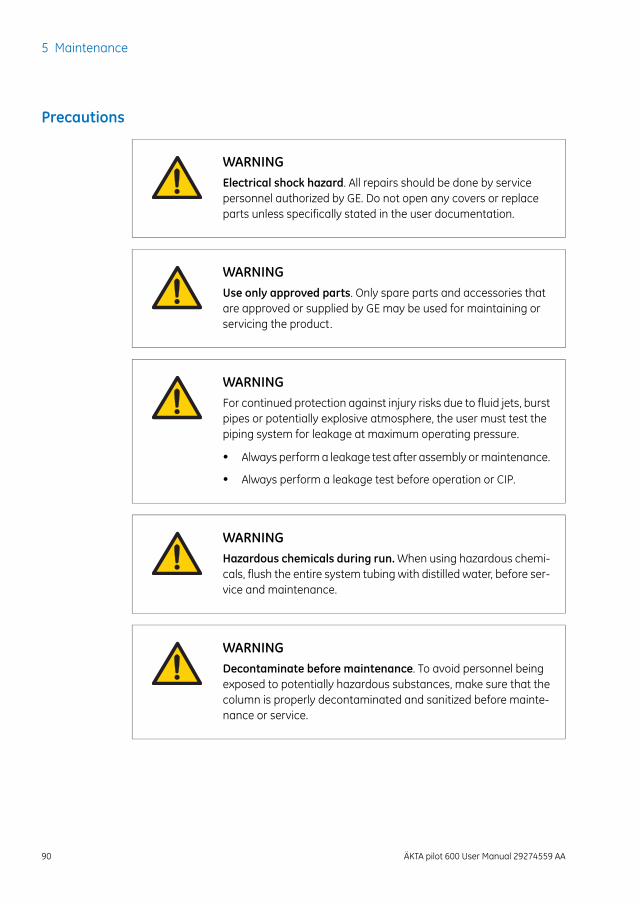
Precautions
WARNINGElectrical shock hazard. All repairs should be done by servicepersonnel authorized by GE. Do not open any covers or replaceparts unless specifically stated in the user documentation.
WARNINGUse only approved parts. Only spare parts and accessories thatare approved or supplied by GE may be used for maintaining orservicing the product.
WARNINGFor continued protection against injury risks due to fluid jets, burstpipes or potentially explosive atmosphere, the user must test thepiping system for leakage at maximum operating pressure.
• Always performa leakage test after assembly ormaintenance.
• Always perform a leakage test before operation or CIP.
WARNINGHazardous chemicals during run.When using hazardous chemi-cals, flush the entire system tubing with distilled water, before ser-vice and maintenance.
WARNINGDecontaminate before maintenance. To avoid personnel beingexposed to potentially hazardous substances, make sure that thecolumn is properly decontaminated and sanitized before mainte-nance or service.
90 ÄKTA pilot 600 User Manual 29274559 AA
5 Maintenance
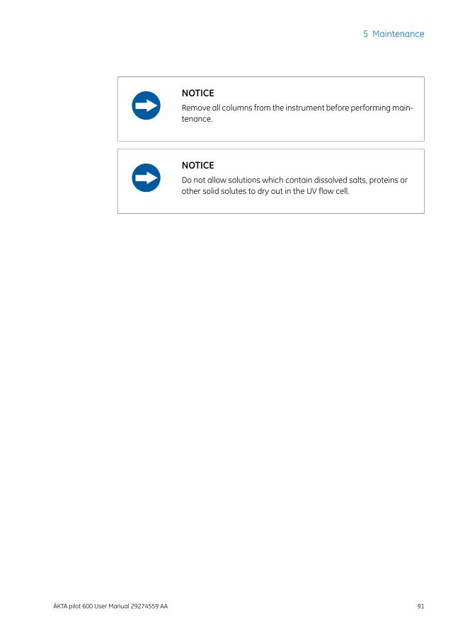
NOTICERemove all columns from the instrument before performingmain-tenance.
NOTICEDo not allow solutions which contain dissolved salts, proteins orother solid solutes to dry out in the UV flow cell.
ÄKTA pilot 600 User Manual 29274559 AA 91
5 Maintenance
5.1 Maintenance manager
IntroductionTheMaintenance Manager in UNICORN software displays general information and op-erational statistics for the ÄKTA pilot 600 system and modules. It also allows creation ofautomatednotifications formaintenanceactions, basedoncalendar timeandoperationalstatistics. A set of predefined notifications is provided, and custom notifications may becreated.
Using theMaintenanceManagerFor details of how to use theMaintenanceManager, refer to theUNICORNAdministrationand Technical Manual.
92 ÄKTA pilot 600 User Manual 29274559 AA
5 Maintenance5.1 Maintenance manager
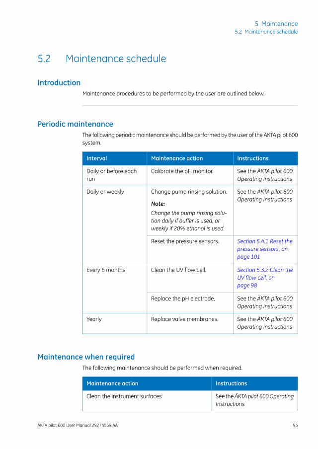
5.2 Maintenance schedule
IntroductionMaintenance procedures to be performed by the user are outlined below.
Periodic maintenanceThe followingperiodicmaintenance should be performedby the user of theÄKTApilot 600system.
InstructionsMaintenance actionInterval
See the ÄKTA pilot 600Operating Instructions
Calibrate the pH monitor.Daily or before eachrun
See the ÄKTA pilot 600Operating Instructions
Change pump rinsing solution.
Note:
Change the pump rinsing solu-tion daily if buffer is used, orweekly if 20% ethanol is used.
Daily or weekly
Section 5.4.1 Reset thepressure sensors, onpage 101
Reset the pressure sensors.
Section 5.3.2 Clean theUV flow cell, onpage 98
Clean the UV flow cell.Every 6 months
See the ÄKTA pilot 600Operating Instructions
Replace the pH electrode.
See the ÄKTA pilot 600Operating Instructions
Replace valve membranes.Yearly
Maintenance when requiredThe following maintenance should be performed when required.
InstructionsMaintenance action
See theÄKTApilot 600OperatingInstructions
Clean the instrument surfaces
ÄKTA pilot 600 User Manual 29274559 AA 93
5 Maintenance5.2 Maintenance schedule
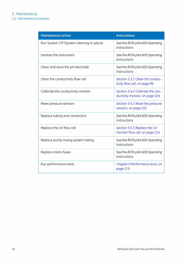
InstructionsMaintenance action
See theÄKTApilot 600OperatingInstructions
Run System CIP (System cleaning-in-place)
See theÄKTApilot 600OperatingInstructions
Sanitize the instrument
See theÄKTApilot 600OperatingInstructions
Clean and store the pH electrode
Section 5.3.1 Clean the conduc-tivity flow cell, on page 96
Clean the conductivity flow cell
Section 5.4.2 Calibrate the con-ductivity monitor, on page 104
Calibrate the conductivity monitor
Section 5.4.1 Reset the pressuresensors, on page 101
Reset pressure sensors
See theÄKTApilot 600OperatingInstructions
Replace tubing and connectors
Section 5.5.3 Replace the UVmonitor flow cell, on page 114
Replace the UV flow cell
See theÄKTApilot 600OperatingInstructions
Replace pump rinsing system tubing
See theÄKTApilot 600OperatingInstructions
Replace mains fuses
Chapter 6 Performance tests, onpage 119
Run performance tests
94 ÄKTA pilot 600 User Manual 29274559 AA
5 Maintenance5.2 Maintenance schedule
5.3 Cleaning procedures
About this sectionThis section describes procedures for cleaning the ÄKTA pilot 600 instrument and com-ponents. See theÄKTApilot 600Operating Instructions for additional cleaning instructions.
For column cleaning and storage procedures, refer to the column instructions.Note:Refer to the computer documentation for recommendations for cleaning thecomputer equipment.
In this sectionThis section contains the following subsections:
See pageSection
965.3.1 Clean the conductivity flow cell
985.3.2 Clean the UV flow cell
ÄKTA pilot 600 User Manual 29274559 AA 95
5 Maintenance5.3 Cleaning procedures
5.3.1 Clean the conductivity flow cell
Maintenance intervalClean the conductivity flow cell when the signal is unstable orwhen unexpected readingsare obtained.
Required materialThe following materials are required:
• Luer-to-SNAP connector (see Luer-SNAP 3.2 connectors, on page 25)
• Waste container (for example, 250 mL flask or beaker)
• Syringe, 25 mL
• 1 M NaOH
• Distilled water
ProcedureFollow the steps below to clean the conductivity flow cell. The same procedure appliesto both pre- and post-column conductivity monitors.
WARNINGCorrosive substance. NaOH is corrosive and therefore dangerousto health. When using hazardous chemicals, avoid spillage andwear protective glasses and other suitable Personal ProtectiveEquipment (PPE).
ActionStep
Disconnect the tubing from the bottom of the conductivity monitor and re-place it with a Luer-to-SNAP connector (see Luer-SNAP 3.2 connectors, onpage 25).
1
96 ÄKTA pilot 600 User Manual 29274559 AA
5 Maintenance5.3 Cleaning procedures5.3.1 Clean the conductivity flow cell
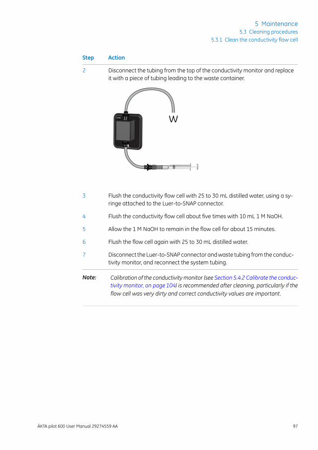
ActionStep
Disconnect the tubing from the top of the conductivity monitor and replaceit with a piece of tubing leading to the waste container.
2
W
Flush the conductivity flow cell with 25 to 30 mL distilled water, using a sy-ringe attached to the Luer-to-SNAP connector.
3
Flush the conductivity flow cell about five times with 10 mL 1 M NaOH.4
Allow the 1 M NaOH to remain in the flow cell for about 15 minutes.5
Flush the flow cell again with 25 to 30 mL distilled water.6
Disconnect the Luer-to-SNAPconnector andwaste tubing from the conduc-tivity monitor, and reconnect the system tubing.
7
Calibration of the conductivitymonitor (see Section 5.4.2 Calibrate the conduc-tivity monitor, on page104) is recommended after cleaning, particularly if theflow cell was very dirty and correct conductivity values are important.
Note:
ÄKTA pilot 600 User Manual 29274559 AA 97
5 Maintenance5.3 Cleaning procedures
5.3.1 Clean the conductivity flow cell
5.3.2 Clean the UV flow cell
Maintenance intervalClean the UV flow cell every six months, or when required.
NOTICEKeepUV flowcell clean. Do not allow solutions containingdissolvedsalts, proteins or other solid solutes to dry out in the flow cell. Donot allow particles to enter the flow cell, as damage to the flow cellmay occur.
Required materialThe following materials are required:
• Luer-to-SNAP connector (see Luer-SNAP 3.2 connectors, on page 25)
• Waste container
• Syringe, 25 to 30 mL
• Detergent solution (e.g., Decon™ 90, Deconex™ 11, or RBS™ 25), diluted accordingto the manufacturer's instructions.
• Distilled water
ProcedureFollow the steps below to clean the UV flow cell.
ActionStep
Disconnect the tubing from the bottomof theUVmonitor and replace it witha Luer-to- SNAP connector.
1
98 ÄKTA pilot 600 User Manual 29274559 AA
5 Maintenance5.3 Cleaning procedures5.3.2 Clean the UV flow cell
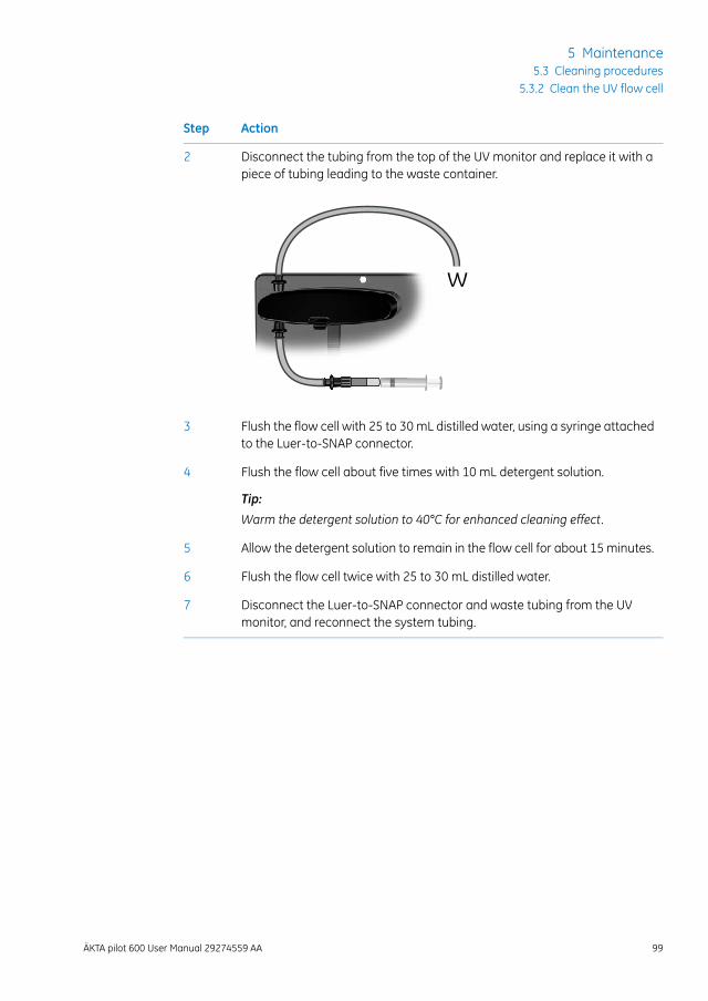
ActionStep
Disconnect the tubing from the top of the UV monitor and replace it with apiece of tubing leading to the waste container.
2
W
Flush the flow cell with 25 to 30 mL distilled water, using a syringe attachedto the Luer-to-SNAP connector.
3
Flush the flow cell about five times with 10 mL detergent solution.
Tip:
Warm the detergent solution to 40°C for enhanced cleaning effect.
4
Allow the detergent solution to remain in the flow cell for about 15 minutes.5
Flush the flow cell twice with 25 to 30 mL distilled water.6
Disconnect the Luer-to-SNAP connector and waste tubing from the UVmonitor, and reconnect the system tubing.
7
ÄKTA pilot 600 User Manual 29274559 AA 99
5 Maintenance5.3 Cleaning procedures
5.3.2 Clean the UV flow cell
5.4 Calibration procedures
About this sectionThis section provides instructions for calibration procedures that can be performed usingthe System Controlmodule in UNICORN software.
In this sectionThis section contains the following subsections.
See pageSection
1015.4.1 Reset the pressure sensors
1045.4.2 Calibrate the conductivity monitor
100 ÄKTA pilot 600 User Manual 29274559 AA
5 Maintenance5.4 Calibration procedures
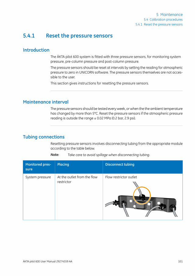
5.4.1 Reset the pressure sensors
IntroductionThe ÄKTA pilot 600 system is fitted with three pressure sensors, for monitoring systempressure, pre-column pressure and post-column pressure.
The pressure sensors should be reset at intervals by setting the reading for atmosphericpressure to zero in UNICORN software. The pressure sensors themselves are not acces-sible to the user.
This section gives instructions for resetting the pressure sensors.
Maintenance intervalThe pressure sensors should be tested everyweek, orwhen the the ambient temperaturehas changed by more than 5°C. Reset the pressure sensors if the atmospheric pressurereading is outside the range ± 0.02 MPa (0.2 bar, 2.9 psi).
Tubing connectionsResetting pressure sensors involves disconnecting tubing from the appropriate moduleaccording to the table below.
Take care to avoid spillage when disconnecting tubing.Note:
Disconnect tubingPlacingMonitored pres-sure
Flow restrictor outletAt the outlet from the flowrestrictor
System pressure
ÄKTA pilot 600 User Manual 29274559 AA 101
5 Maintenance5.4 Calibration procedures
5.4.1 Reset the pressure sensors
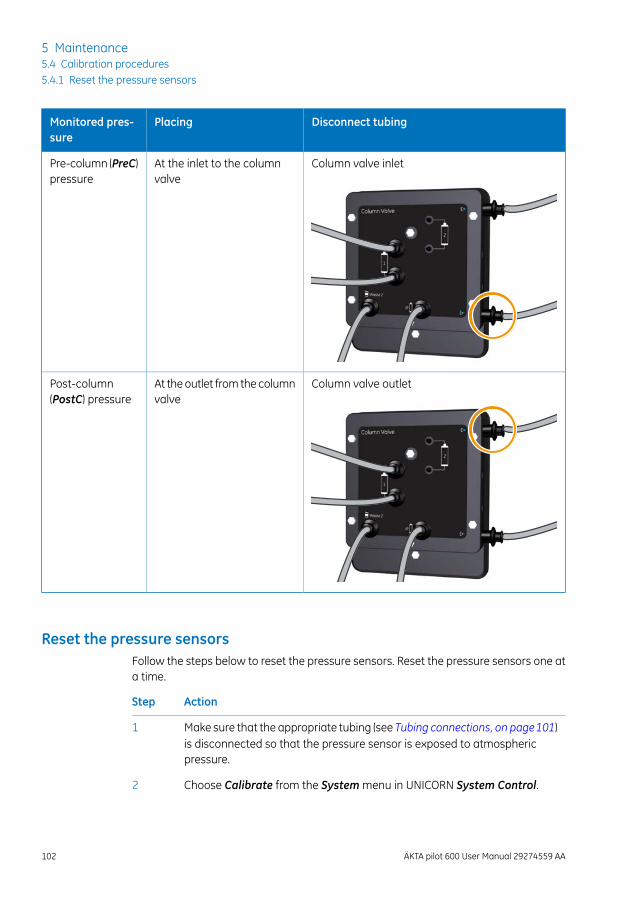
Disconnect tubingPlacingMonitored pres-sure
Column valve inletAt the inlet to the columnvalve
Pre-column (PreC)pressure
Column valve outletAt the outlet from the columnvalve
Post-column(PostC) pressure
Reset the pressure sensorsFollow the steps below to reset the pressure sensors. Reset the pressure sensors one ata time.
ActionStep
Make sure that the appropriate tubing (see Tubing connections, on page101)is disconnected so that the pressure sensor is exposed to atmosphericpressure.
1
Choose Calibrate from the Systemmenu in UNICORN System Control.2
102 ÄKTA pilot 600 User Manual 29274559 AA
5 Maintenance5.4 Calibration procedures5.4.1 Reset the pressure sensors
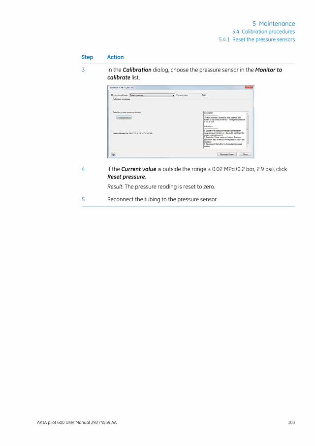
ActionStep
In the Calibration dialog, choose the pressure sensor in theMonitor tocalibrate list.
3
If the Current value is outside the range ± 0.02 MPa (0.2 bar, 2.9 psi), clickReset pressure.
4
Result: The pressure reading is reset to zero.
Reconnect the tubing to the pressure sensor.5
ÄKTA pilot 600 User Manual 29274559 AA 103
5 Maintenance5.4 Calibration procedures
5.4.1 Reset the pressure sensors
5.4.2 Calibrate the conductivity monitor
IntroductionTwo types of calibration can be performed:
• Conductivity monitor - user calibration: Calibrates the conductivity cell constant.
• Conductivity monitor - factory calibration: Restores the conductivity cell constantto the factory default value.
This section gives instructions for both calibration procedures. The instructions apply toboth pre- and post-column conductivity monitors.
Maintenance intervalWhen to perform the two types of calibrations is as follows:
When to performCalibration type
When the signal is unstable, or when you suspect that thevalue is incorrect.
User calibration
When user calibration fails.Factory calibration
Required materialThe following materials are required:
• Luer-to-SNAP connector (see Luer-SNAP 3.2 connectors, on page 25)
• Waste container
• Syringe, 25 mL
• Calibration solution, either a certified conductivity standard solution (1.0 M KCl) oryour own accurately prepared 1.00 M NaCl.
• Distilled water
User calibration procedureFollow the steps below to calibrate the conductivity monitor.
104 ÄKTA pilot 600 User Manual 29274559 AA
5 Maintenance5.4 Calibration procedures5.4.2 Calibrate the conductivity monitor
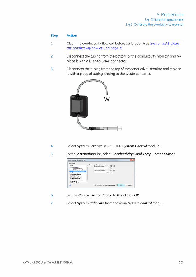
ActionStep
Clean the conductivity flow cell before calibration (see Section 5.3.1 Cleanthe conductivity flow cell, on page 96).
1
Disconnect the tubing from the bottom of the conductivity monitor and re-place it with a Luer-to-SNAP connector.
2
Disconnect the tubing from the top of the conductivity monitor and replaceit with a piece of tubing leading to the waste container.
3
W
Select System:Settings in UNICORN System Controlmodule.4
In the Instructions list, select Conductivity:Cond Temp Compensation.5
Set the Compensation factor to 0 and click OK.6
Select System:Calibrate from the main System controlmenu.7
ÄKTA pilot 600 User Manual 29274559 AA 105
5 Maintenance5.4 Calibration procedures
5.4.2 Calibrate the conductivity monitor
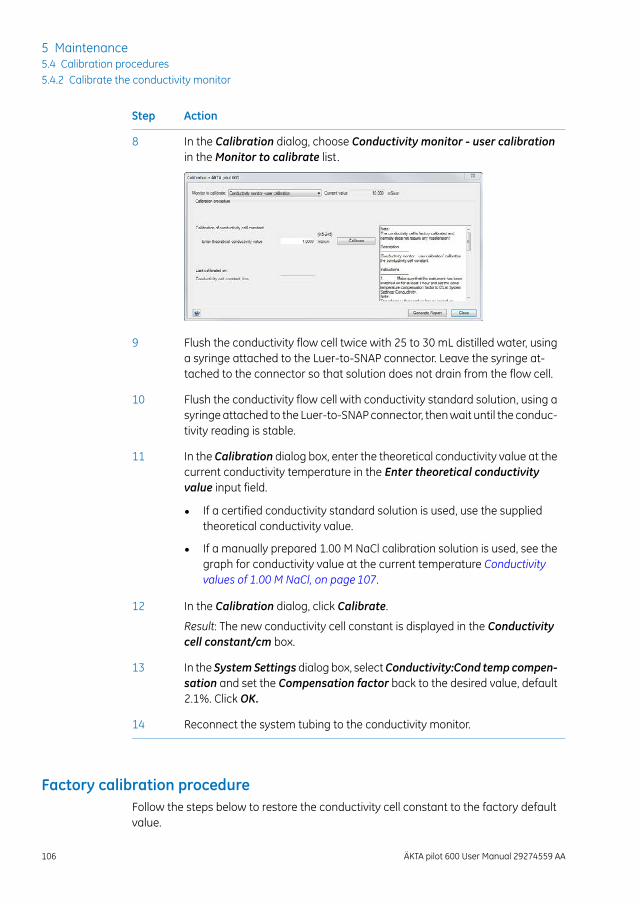
ActionStep
In the Calibration dialog, choose Conductivity monitor - user calibrationin theMonitor to calibrate list.
8
Flush the conductivity flow cell twice with 25 to 30 mL distilled water, usinga syringe attached to the Luer-to-SNAP connector. Leave the syringe at-tached to the connector so that solution does not drain from the flow cell.
9
Flush the conductivity flow cell with conductivity standard solution, using asyringe attached to the Luer-to-SNAP connector, thenwait until the conduc-tivity reading is stable.
10
In the Calibration dialog box, enter the theoretical conductivity value at thecurrent conductivity temperature in the Enter theoretical conductivityvalue input field.
11
• If a certified conductivity standard solution is used, use the suppliedtheoretical conductivity value.
• If a manually prepared 1.00 M NaCl calibration solution is used, see thegraph for conductivity value at the current temperature Conductivityvalues of 1.00 M NaCl, on page 107.
In the Calibration dialog, click Calibrate.12
Result: The new conductivity cell constant is displayed in the Conductivitycell constant/cm box.
In the SystemSettings dialog box, selectConductivity:Cond temp compen-sation and set the Compensation factor back to the desired value, default2.1%. Click OK.
13
Reconnect the system tubing to the conductivity monitor.14
Factory calibration procedureFollow the steps below to restore the conductivity cell constant to the factory defaultvalue.
106 ÄKTA pilot 600 User Manual 29274559 AA
5 Maintenance5.4 Calibration procedures5.4.2 Calibrate the conductivity monitor
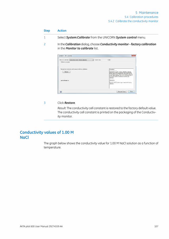
ActionStep
Select System:Calibrate from the UNICORN System controlmenu.1
In theCalibrationdialog, chooseConductivitymonitor - factory calibrationin theMonitor to calibrate list.
2
Click Restore.3
Result: The conductivity cell constant is restored to the factory default value.The conductivity cell constant is printed on the packaging of the Conductiv-ity monitor.
Conductivity values of 1.00 MNaCl
The graph below shows the conductivity value for 1.00 M NaCl solution as a function oftemperature.
ÄKTA pilot 600 User Manual 29274559 AA 107
5 Maintenance5.4 Calibration procedures
5.4.2 Calibrate the conductivity monitor
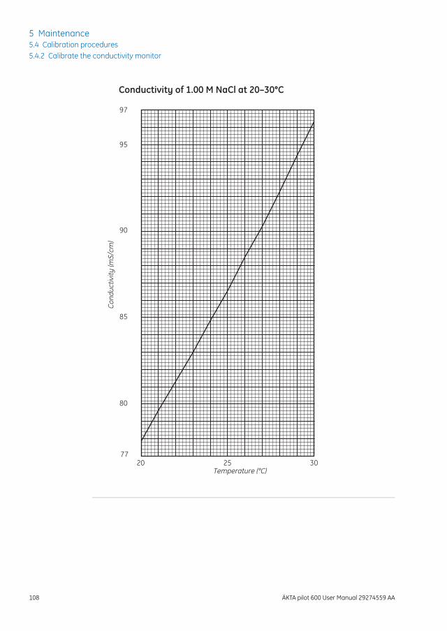
03520277
80
85
90
95
97
Temperature (°C)
Cond
uctiv
ity (m
S/cm
)
Conductivity of 1.00 M NaCl at 20–30°C
108 ÄKTA pilot 600 User Manual 29274559 AA
5 Maintenance5.4 Calibration procedures5.4.2 Calibrate the conductivity monitor
5.5 Replacement procedures
About this sectionThis section gives instructions for the replacement procedures to be performed by theuser of ÄKTA pilot 600 instrument.
In this sectionThis section contains the following subsections:
See pageSection
1115.5.1 Replace the pH electrode
1125.5.2 Replace the Mixer module
1145.5.3 Replace the UV monitor flow cell
1185.5.4 Replace valve fronts
Precautions
WARNINGDisconnect power. Always disconnect power from the instrumentbefore replacing any component on the instrument, unless statedotherwise in the user documentation.
WARNINGHazardous chemicals during run.When using hazardous chemi-cals, flush the entire system tubing with distilled water, before ser-vice and maintenance.
ÄKTA pilot 600 User Manual 29274559 AA 109
5 Maintenance5.5 Replacement procedures
WARNINGHazardous chemicals. Always empty the system of liquids beforeservice.
WARNINGDecontaminatebeforemaintenance. To avoid exposingpersonnelto potentially hazardous substances, clean and sanitize theÄKTA pilot 600 system before maintenance or service.
110 ÄKTA pilot 600 User Manual 29274559 AA
5 Maintenance5.5 Replacement procedures
5.5.1 Replace the pH electrode
Maintenance intervalReplace the pH electrode every six months, or when required.
Required materialThe following materials are required:
• pH electrode
• distilled water
• pH electrode storage solution (1:1 pH 4 standard buffer:1 M KNO3)
• pH 4 and pH 7 standard buffers
ProcedureFollow the steps below to replace the pH electrode.
CAUTIONpH-electrode. Handle the pH-electrode with care. The glass tipmay break and cause injury.
Follow the steps below to replace the pH electrode.
ActionStep
Disconnect the pH electrode cable from the connection on the front of thepH monitor.
1
Unscrew the locking ring nut of the pH electrode and remove the electrode.2
Fit a new pH electrode as described in the ÄKTA pilot 600 OperatingInstructions.
3
Allow the electrode to remain in storage solution for at least 1 h before use.4
Calibrate the newpHelectrode (see theÄKTApilot 600Operating Instructions).7
ÄKTA pilot 600 User Manual 29274559 AA 111
5 Maintenance5.5 Replacement procedures
5.5.1 Replace the pH electrode
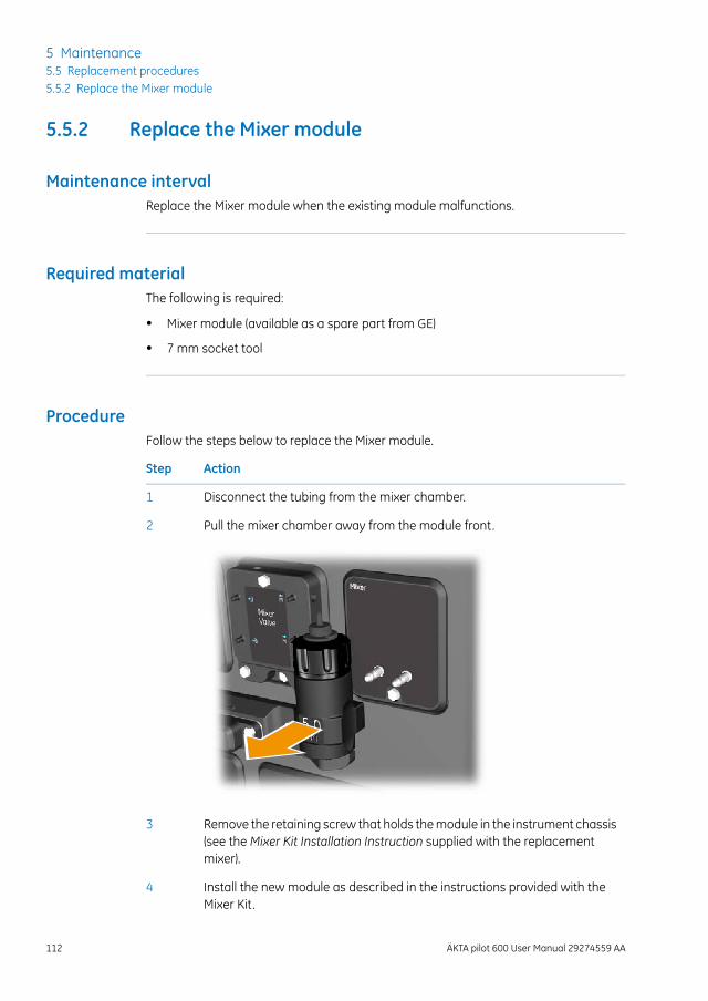
5.5.2 Replace the Mixer module
Maintenance intervalReplace the Mixer module when the existing module malfunctions.
Required materialThe following is required:
• Mixer module (available as a spare part from GE)
• 7 mm socket tool
ProcedureFollow the steps below to replace the Mixer module.
ActionStep
Disconnect the tubing from the mixer chamber.1
Pull the mixer chamber away from the module front.2
Remove the retaining screw that holds themodule in the instrument chassis(see the Mixer Kit Installation Instruction supplied with the replacementmixer).
3
Install the new module as described in the instructions provided with theMixer Kit.
4
112 ÄKTA pilot 600 User Manual 29274559 AA
5 Maintenance5.5 Replacement procedures5.5.2 Replace the Mixer module
ActionStep
Reconnect the tubing to the mixer chamber.5
Flush the systemwithwater or buffer to remove the air from the newmodule.6
ÄKTA pilot 600 User Manual 29274559 AA 113
5 Maintenance5.5 Replacement procedures
5.5.2 Replace the Mixer module
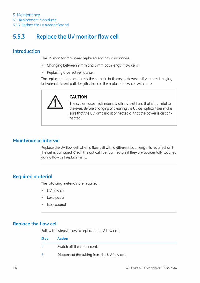
5.5.3 Replace the UV monitor flow cell
IntroductionThe UV monitor may need replacement in two situations:
• Changing between 2 mm and 5 mm path length flow cells
• Replacing a defective flow cell
The replacement procedure is the same in both cases. However, if you are changingbetween different path lengths, handle the replaced flow cell with care.
CAUTIONThe system uses high intensity ultra-violet light that is harmful tothe eyes. Before changing or cleaning theUV cell optical fiber,makesure that the UV lamp is disconnected or that the power is discon-nected.
Maintenance intervalReplace the UV flow cell when a flow cell with a different path length is required, or ifthe cell is damaged. Clean the optical fiber connectors if they are accidentally touchedduring flow cell replacement.
Required materialThe following materials are required:
• UV flow cell
• Lens paper
• Isopropanol
Replace the flow cellFollow the steps below to replace the UV flow cell.
ActionStep
Switch off the instrument.1
Disconnect the tubing from the UV flow cell.2
114 ÄKTA pilot 600 User Manual 29274559 AA
5 Maintenance5.5 Replacement procedures5.5.3 Replace the UV monitor flow cell
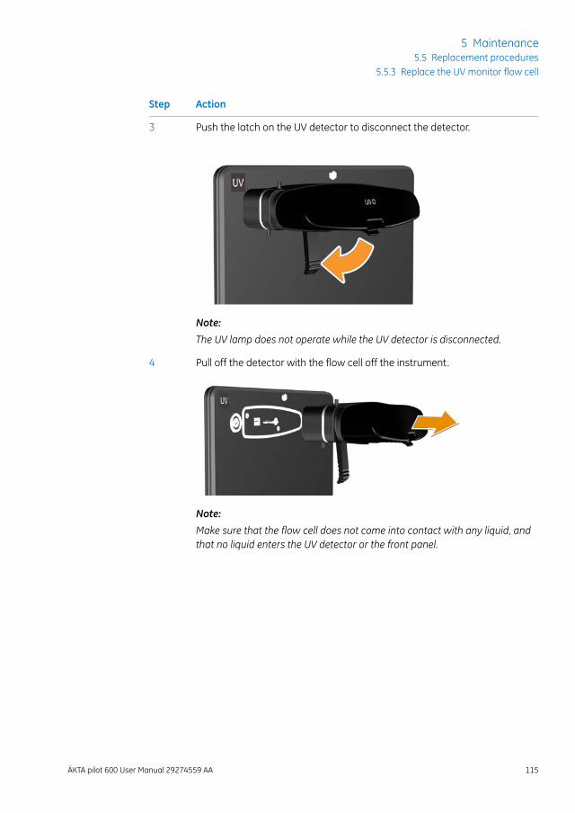
ActionStep
Push the latch on the UV detector to disconnect the detector.3
Note:
The UV lamp does not operate while the UV detector is disconnected.
Pull off the detector with the flow cell off the instrument.4
Note:
Make sure that the flow cell does not come into contact with any liquid, andthat no liquid enters the UV detector or the front panel.
ÄKTA pilot 600 User Manual 29274559 AA 115
5 Maintenance5.5 Replacement procedures
5.5.3 Replace the UV monitor flow cell
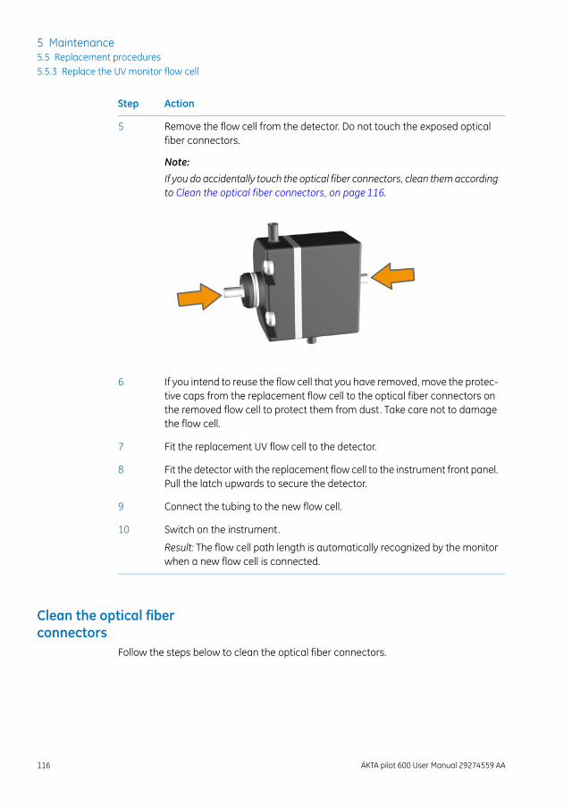
ActionStep
Remove the flow cell from the detector. Do not touch the exposed opticalfiber connectors.
Note:
If you do accidentally touch the optical fiber connectors, clean themaccordingto Clean the optical fiber connectors, on page 116.
5
If you intend to reuse the flow cell that you have removed, move the protec-tive caps from the replacement flow cell to the optical fiber connectors onthe removed flow cell to protect them from dust. Take care not to damagethe flow cell.
6
Fit the replacement UV flow cell to the detector.7
Fit the detector with the replacement flow cell to the instrument front panel.Pull the latch upwards to secure the detector.
8
Connect the tubing to the new flow cell.9
Switch on the instrument.10
Result: The flow cell path length is automatically recognized by the monitorwhen a new flow cell is connected.
Clean the optical fiberconnectors
Follow the steps below to clean the optical fiber connectors.
116 ÄKTA pilot 600 User Manual 29274559 AA
5 Maintenance5.5 Replacement procedures5.5.3 Replace the UV monitor flow cell
WARNINGHazardous substances.When using hazardous chemicals, takeall suitable protective measures, such as wearing protectiveclothing, glasses and gloves resistant to the substances used. Fol-low local and/or national regulations for safe operation andmaintenance of the product.
ActionStep
Wipe the optical fiber connectors with a lens paper moistened with iso-propanol.
1
Wipe the optical fiber connectors dry with lens paper.2
ÄKTA pilot 600 User Manual 29274559 AA 117
5 Maintenance5.5 Replacement procedures
5.5.3 Replace the UV monitor flow cell
5.5.4 Replace valve fronts
When to replace the valve frontsThe valve fronts only need replacing if they are damaged.
ProcedureObtain a new valve front from GE, then follow the procedure for replacing valve mem-branes (described in the ÄKTA pilot 600 Operating Instructions).
118 ÄKTA pilot 600 User Manual 29274559 AA
5 Maintenance5.5 Replacement procedures5.5.4 Replace valve fronts
6 Performance tests
About this chapterPerformance tests allow the user to test the integrity and functional aspects of thewholeÄKTA pilot 600 system or of individual components.
This chapter describes in general terms how to access, run, and assess performancetests. Detailed on-screen instructions are provided in the UNICORN software for eachtest.
In this chapterThis chapter contains the following sections:
See pageSection
1206.1 When to run performance tests
1226.2 How to run performance tests
1266.3 How to evaluate performance tests
ÄKTA pilot 600 User Manual 29274559 AA 119
6 Performance tests
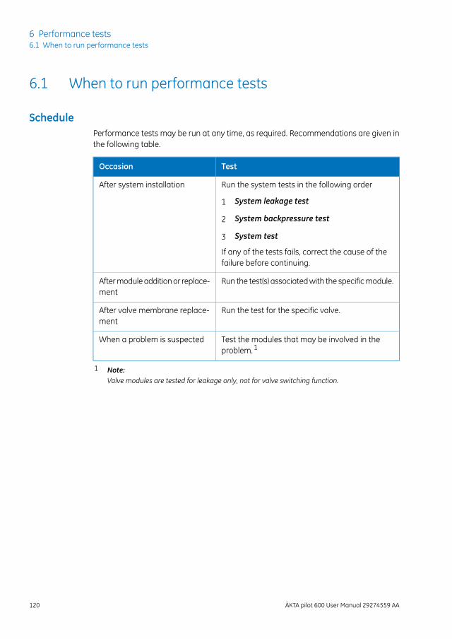
6.1 When to run performance tests
SchedulePerformance tests may be run at any time, as required. Recommendations are given inthe following table.
TestOccasion
Run the system tests in the following orderAfter system installation
1 System leakage test
2 System backpressure test
3 System test
If any of the tests fails, correct the cause of thefailure before continuing.
Run the test(s) associatedwith the specificmodule.Aftermoduleadditionor replace-ment
Run the test for the specific valve.After valve membrane replace-ment
Test the modules that may be involved in theproblem.1
When a problem is suspected
1 Note:Valve modules are tested for leakage only, not for valve switching function.
120 ÄKTA pilot 600 User Manual 29274559 AA
6 Performance tests6.1 When to run performance tests
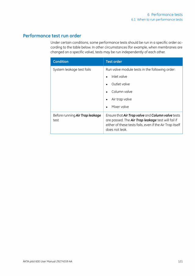
Performance test run orderUnder certain conditions, some performance tests should be run in a specific order ac-cording to the table below. In other circumstances (for example, when membranes arechanged on a specific valve), tests may be run independently of each other.
Test orderCondition
Run valve module tests in the following order:System leakage test fails
• Inlet valve
• Outlet valve
• Column valve
• Air trap valve
• Mixer valve
Ensure thatAir Trap valveandColumnvalve testsare passed. The Air Trap leakage test will fail ifeither of these tests fails, even if the Air Trap itselfdoes not leak.
Before runningAir Trap leakagetest
ÄKTA pilot 600 User Manual 29274559 AA 121
6 Performance tests6.1 When to run performance tests
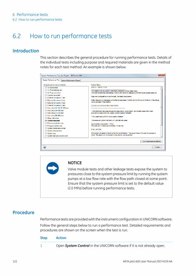
6.2 How to run performance tests
IntroductionThis section describes the general procedure for running performance tests. Details ofthe individual tests including purpose and required materials are given in the methodnotes for each test method. An example is shown below.
NOTICEValve module tests and other leakage tests expose the system topressures close to the systempressure limit by running the systempumps at a low flow rate with the flow path closed at some point.Ensure that the system pressure limit is set to the default value(2.0 MPa) before running performance tests.
ProcedurePerformance tests are providedwith the instrument configuration inUNICORN software.
Follow the general steps below to run a performance test. Detailed requirements andprocedures are shown on the screen when the test is run.
ActionStep
Open System Control in the UNICORN software if it is not already open.1
122 ÄKTA pilot 600 User Manual 29274559 AA
6 Performance tests6.2 How to run performance tests
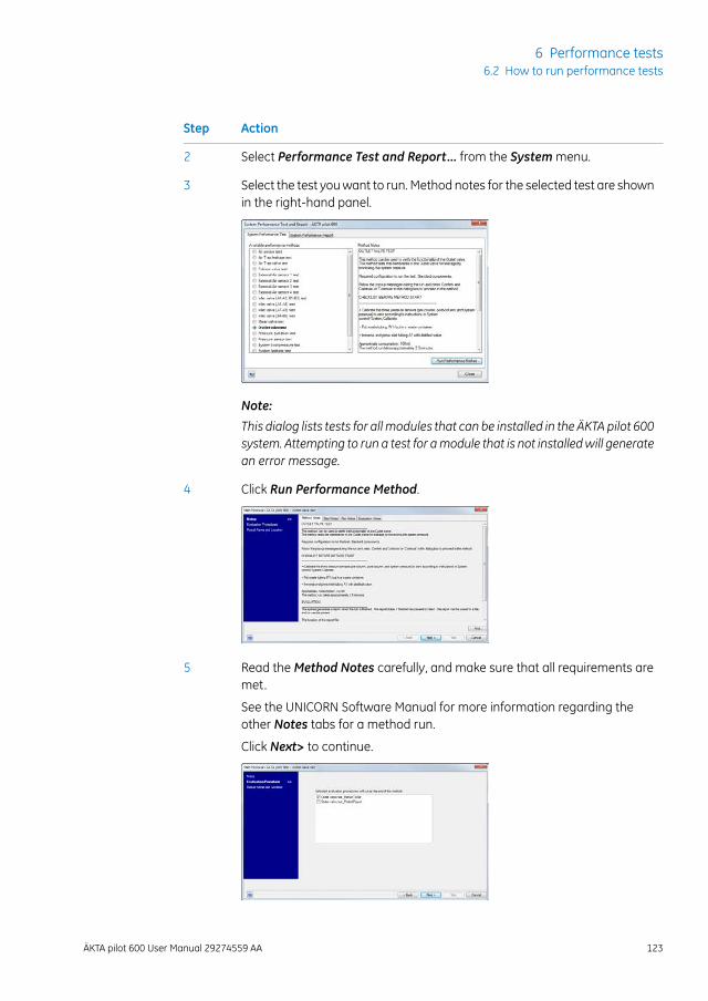
ActionStep
Select Performance Test and Report... from the Systemmenu.2
Select the test youwant to run. Method notes for the selected test are shownin the right-hand panel.
3
Note:
This dialog lists tests for all modules that can be installed in the ÄKTA pilot 600system. Attempting to run a test for amodule that is not installedwill generatean error message.
Click Run Performance Method.4
Read theMethod Notes carefully, and make sure that all requirements aremet.
5
See the UNICORN Software Manual for more information regarding theother Notes tabs for a method run.
Click Next> to continue.
ÄKTA pilot 600 User Manual 29274559 AA 123
6 Performance tests6.2 How to run performance tests

ActionStep
Select whether the test report should be saved to a file and/or printed.
Note:
Sending the report to a printer requires that a system printer is installed onthe UNICORN Instrument Server (see the UNICORN Administration and Tech-nical Manual for details).
6
Click Next> to continue.
Specify the details of the result file from the performance test.
Note:
The result file is separate from the test report. The report will be generatedeven if No result is selected.
7
Click Start to start the performance test.
Follow any instructions that are shown on the screen.8
The progress of the performance test is shown in the chromatogram pane and can becustomized in the same way as any chromatogram.
Required materialsMaterials required for performance tests, in addition to distilled water, are specified inthe method notes for the test and summarized in the table below.
Required materialTest
2 L 1% acetone (v/v) in 1.0 M NaClSystem test/System test precolumn cond Reference capillary 1
Reference capillary 2Column valve test
Short lengths of i.d. 3.2mmwith SNAPconnectorsto replace columns.
Reference capillary 2Pressure pulsation test
124 ÄKTA pilot 600 User Manual 29274559 AA
6 Performance tests6.2 How to run performance tests
Reference capillaries are providedwith the system, andmay also be obtained separatelyfrom GE.
ÄKTA pilot 600 User Manual 29274559 AA 125
6 Performance tests6.2 How to run performance tests
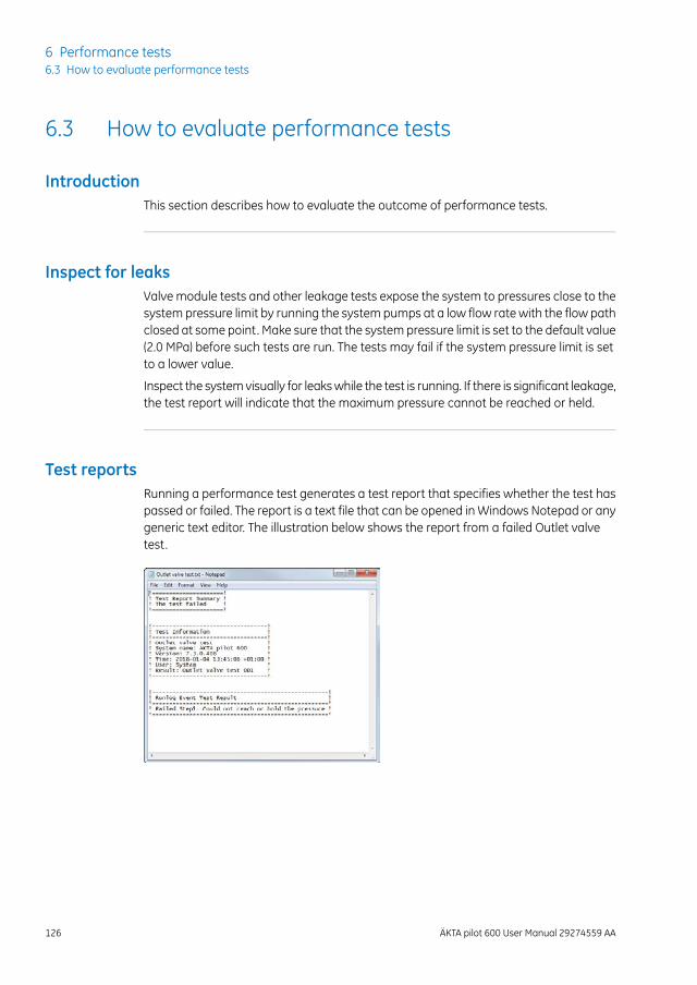
6.3 How to evaluate performance tests
IntroductionThis section describes how to evaluate the outcome of performance tests.
Inspect for leaksValve module tests and other leakage tests expose the system to pressures close to thesystem pressure limit by running the system pumps at a low flow rate with the flow pathclosed at some point. Make sure that the system pressure limit is set to the default value(2.0 MPa) before such tests are run. The tests may fail if the system pressure limit is setto a lower value.
Inspect the systemvisually for leakswhile the test is running. If there is significant leakage,the test report will indicate that the maximum pressure cannot be reached or held.
Test reportsRunning a performance test generates a test report that specifies whether the test haspassed or failed. The report is a text file that can be opened inWindows Notepad or anygeneric text editor. The illustration below shows the report from a failed Outlet valvetest.
126 ÄKTA pilot 600 User Manual 29274559 AA
6 Performance tests6.3 How to evaluate performance tests
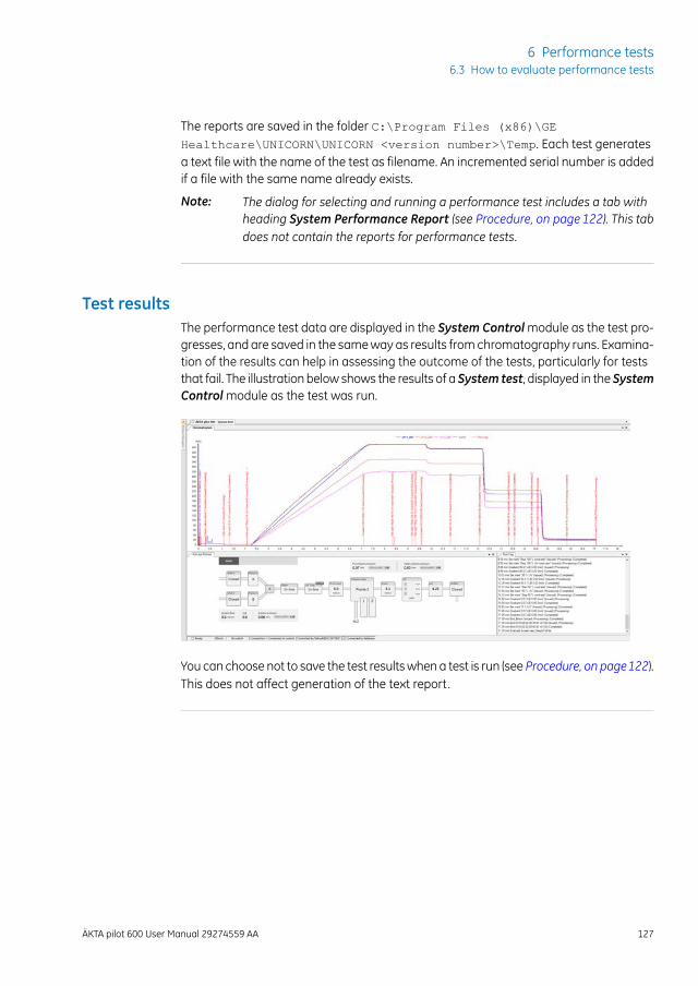
The reports are saved in the folder C:\Program Files (x86)\GE
Healthcare\UNICORN\UNICORN <version number>\Temp. Each test generatesa text file with the name of the test as filename. An incremented serial number is addedif a file with the same name already exists.
The dialog for selecting and running a performance test includes a tab withheading System Performance Report (see Procedure, on page 122). This tabdoes not contain the reports for performance tests.
Note:
Test resultsThe performance test data are displayed in the System Controlmodule as the test pro-gresses, and are saved in the sameway as results fromchromatography runs. Examina-tion of the results can help in assessing the outcome of the tests, particularly for teststhat fail. The illustration below shows the results of a System test, displayed in the SystemControlmodule as the test was run.
You can choose not to save the test resultswhena test is run (see Procedure, on page122).This does not affect generation of the text report.
ÄKTA pilot 600 User Manual 29274559 AA 127
6 Performance tests6.3 How to evaluate performance tests
7 Troubleshooting
About this chapterThis chapter describes actions that should be takenwhen performance tests fail, indicat-ing amalfunction in the system. See Chapter 6 Performance tests, on page119 for infor-mation on how to run performance tests.
Basic troubleshooting is described in the ÄKTA pilot 600 Operating Instructions.
If you have problems that cannot be resolved using the information provided here,contact your GE service organization.
In this chapterThis chapter contains the following sections:
See pageSection
1297.1 System leakage test failure
1307.2 System backpressure test failure
1317.3 System test failure
1337.4 Other performance tests
128 ÄKTA pilot 600 User Manual 29274559 AA
7 Troubleshooting
7.1 System leakage test failure
DescriptionThe System leakage test tests the system flowpath for leakage. Leakage from the tubingconnections and valve membranes is tested by monitoring the system pressure. Thefirst step tests the whole flow path up to the oultlet valve at a lower pressure level. Thesecond step tests the flow path up to the column valve at a higher pressure level. Duringeach test step, the systempressure increases slowly and is thenmaintained for a limitedtime. The outcome of the two steps is listed separately in the performance test report.
Corrective actionsIf the System leakage test fails, inspect all tubing connections and valves in the flowpath. Correct the problem according to the table below, and rerun the System leakagetest tomake sure the leakage is corrected. If the problempersists after corrective actionhas been applied, contact your GE representative.
Corrective actionCause of failure
Make sure that the SNAP connectors are correctly fitted.Visible leakage at atubing connector Replace the tubing.
Replace the valve membranes (see the ÄKTA pilot 600Operating Instructions).
Visible leakage at avalve
If the problem persists, replace the valve module.
1 Make sure that both inletsA1andB1have beenprimedwith water.
2 Repeat the test.
3 If the test still fails, run individualmodule tests until theleakage is located.
No visible leakage
ÄKTA pilot 600 User Manual 29274559 AA 129
7 Troubleshooting7.1 System leakage test failure
7.2 System backpressure test failure
DescriptionThe Systembackpressure test tests that the backpressure in the systemdoes not exceeda specified value. Increased backpressure may result from an obstruction in the flowpath such as kinked tubing.
Corrective actionIf the System backpressure test fails, make sure that tubing is not kinked or obstructed.Replace any kinked tubing.
Locate the source of increased backpressure by moving the outlet tubing to the outletport of successive modules, starting with the outlet valve(s) and working systematicallytowards the beginning of the flow path. The backpressure will drop when the blockedmodule is excluded from the flow path.
If the cause of the failure cannot be located, contact your GE service organization.
130 ÄKTA pilot 600 User Manual 29274559 AA
7 Troubleshooting7.2 System backpressure test failure
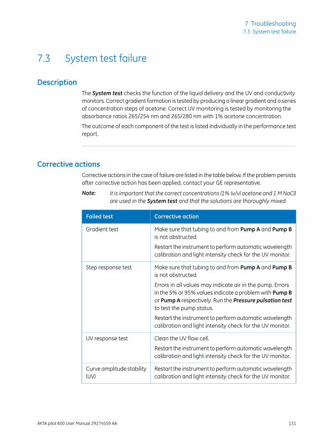
7.3 System test failure
DescriptionThe System test checks the function of the liquid delivery and the UV and conductivitymonitors. Correct gradient formation is tested by producing a linear gradient and a seriesof concentration steps of acetone. Correct UV monitoring is tested by monitoring theabsorbance ratios 265/254 nm and 265/280 nm with 1% acetone concentration.
The outcome of each component of the test is listed individually in the performance testreport.
Corrective actionsCorrective actions in the case of failure are listed in the table below. If the problempersistsafter corrective action has been applied, contact your GE representative.
It is important that the correct concentrations (1% (v/v) acetone and 1MNaCl)are used in the System test and that the solutions are thoroughly mixed.
Note:
Corrective actionFailed test
Make sure that tubing to and from Pump A and Pump Bis not obstructed.
Gradient test
Restart the instrument to performautomaticwavelengthcalibration and light intensity check for the UV monitor.
Make sure that tubing to and from Pump A and Pump Bis not obstructed.
Step response test
Errors in all values may indicate air in the pump. Errorsin the 5%or 95% values indicate a problemwith PumpBor Pump A respectively. Run the Pressure pulsation testto test the pump status.
Restart the instrument to performautomaticwavelengthcalibration and light intensity check for the UV monitor.
Clean the UV flow cell.UV response test
Restart the instrument to performautomaticwavelengthcalibration and light intensity check for the UV monitor.
Restart the instrument to performautomaticwavelengthcalibration and light intensity check for the UV monitor.
Curve amplitude stability(UV)
ÄKTA pilot 600 User Manual 29274559 AA 131
7 Troubleshooting7.3 System test failure
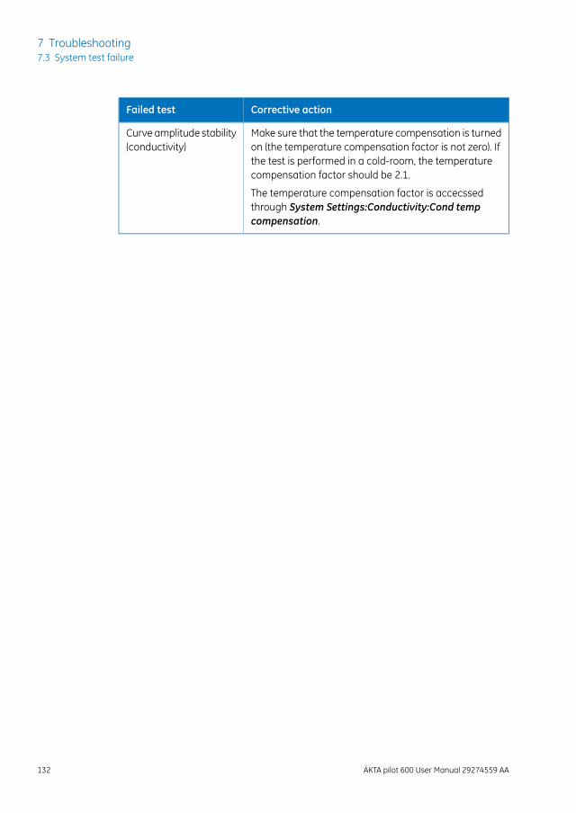
Corrective actionFailed test
Make sure that the temperature compensation is turnedon (the temperature compensation factor is not zero). Ifthe test is performed in a cold-room, the temperaturecompensation factor should be 2.1.
Curve amplitude stability(conductivity)
The temperature compensation factor is accecssedthrough System Settings:Conductivity:Cond tempcompensation.
132 ÄKTA pilot 600 User Manual 29274559 AA
7 Troubleshooting7.3 System test failure
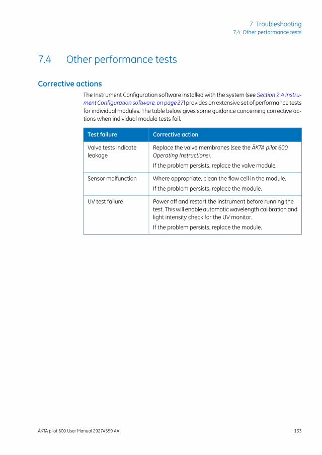
7.4 Other performance tests
Corrective actionsThe Instrument Configuration software installed with the system (see Section 2.4 Instru-ment Configuration software, on page27) provides an extensive set of performance testsfor individual modules. The table below gives some guidance concerning corrective ac-tions when individual module tests fail.
Corrective actionTest failure
Replace the valve membranes (see the ÄKTA pilot 600Operating Instructions).
Valve tests indicateleakage
If the problem persists, replace the valve module.
Where appropriate, clean the flow cell in the module.Sensor malfunction
If the problem persists, replace the module.
Power off and restart the instrument before running thetest. Thiswill enable automaticwavelength calibration andlight intensity check for the UV monitor.
UV test failure
If the problem persists, replace the module.
ÄKTA pilot 600 User Manual 29274559 AA 133
7 Troubleshooting7.4 Other performance tests
8 Reference information
About this chapterSystem specifications, chemical resistance information and other basic reference infor-mation are given in the ÄKTA pilot 600 Operating Instructions and the ÄKTA pilot 600SProduct Documentation for ÄKTA pilot 600S systems. Detailed information specific to theindividual system is provided separatelywith ÄKTA pilot 600R systems. This chapter givesadditional specification details.
In this chapterThis chapter contains the following sections:
See pageSection
1358.1 Component volumes
1368.2 Ordering information
134 ÄKTA pilot 600 User Manual 29274559 AA
8 Reference information
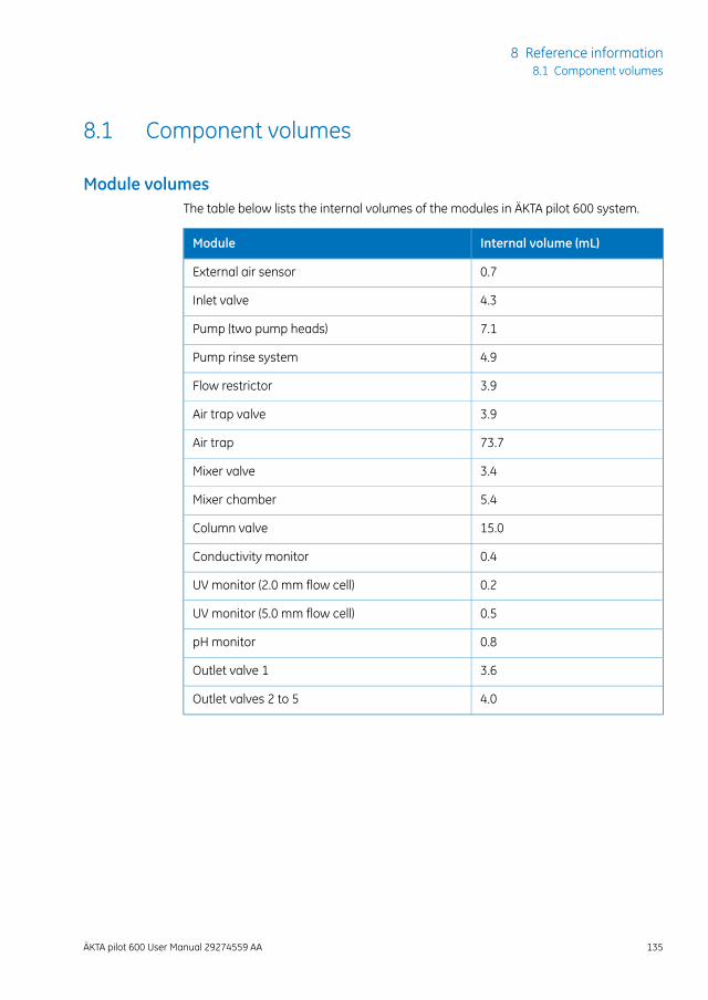
8.1 Component volumes
Module volumesThe table below lists the internal volumes of the modules in ÄKTA pilot 600 system.
Internal volume (mL)Module
0.7External air sensor
4.3Inlet valve
7.1Pump (two pump heads)
4.9Pump rinse system
3.9Flow restrictor
3.9Air trap valve
73.7Air trap
3.4Mixer valve
5.4Mixer chamber
15.0Column valve
0.4Conductivity monitor
0.2UV monitor (2.0 mm flow cell)
0.5UV monitor (5.0 mm flow cell)
0.8pH monitor
3.6Outlet valve 1
4.0Outlet valves 2 to 5
ÄKTA pilot 600 User Manual 29274559 AA 135
8 Reference information8.1 Component volumes
8.2 Ordering information
Visit gelifesciences.comRefer to our website www.gelifesciences.com/aktapilot or GE representative for furtherinformation about the following topics:
• System recommendations
• Literature
• Service
• Training
• Accessories
• Ordering information
Spare partsYour local GE representative can suggest recommended spare parts.
Contact informationContact information can be found on the back page of this document.
136 ÄKTA pilot 600 User Manual 29274559 AA
8 Reference information8.2 Ordering information
IndexAAccessories
extension box, 22extension stand, 24I/O-box, 23included, 21Module front panel withrails, 25optional, 22
Air sensorin air trap valve, 42
Air sensor alarm, 43Air trap, 41Air trap valve, 41Applying sample
from system inlet, 63
BBackpressure test, 130
CCalibration procedures, 100Cleaning
conductivity cell, 96UV flow cell, 98
Cleaning procedures, 95Cold cabinet, 87
precautions, 87Cold room, 87Column pressure, 50Column valve, 47Conditional fractionation, 75Conductivity cell
cleaning, 96Conductivity monitor, 51
calibration, 104clean the conductivity flowcell, 96factory calibration, 106user calibration, 104
Conductivity values1.00 M NaCl, 107
Connectors, 21
DDelta column pressure, 50Documentation
on the web, 13Documentation package
regulatory version, 10standard version, 9
Dual pump flow, 81for isocratic applications, 81gradient applications, 81in methods, 83manual instructions, 82Process Picture, 82
EExtension box, 22Extension stand, 24External air sensors, 30
FFixed volume fractionation, 72Flow diagram, 19Flow path, 19Flow restrictor, 37Fractionation, 71
conditional, 75practical aspects, 76settings, 71types, 72
II/O-box, 23Important user information, 6Included accessories, 21Inlet tubing, 34Inlet valves, 33In-line filter, 45Inspect for leaks, 126Instrument
front panel, 16versions, 16
Instrument Configuration soft-ware, 27
installing, 27updating, 27
ÄKTA pilot 600 User Manual 29274559 AA 137
Index
Intelligent packing, 77method, 77
Intended use, 6
LLeakage test, 129Liquid flow path, 19Luer-to-SNAP connectors, 25
MMaintenance instructions
inOperating Instructions, 89Maintenance Manager, 92Maintenance program, 93Maintenance schedule, 93Manual scope, 5Mixer, 39
replace mixer, 112replacing, 112
Mixer valve, 39Module front panel withrails, 25Module volumes, 135Monitoringcolumnpressure, 50
NNotes and tips, 8
OOutlet tubing, 58Outlet valves, 57
PPeak detection, 73Peak fractionation, 72
settings, 73Performance tests, 119
evaluating, 126required materials, 124running, 122test reports, 126test results, 127
Periodic maintenance, 93Phase properties for sampleapplication
from Superloop, 69from system inlet, 63
pH electrodereplacing, 111
pH monitor, 55replace the pH elec-trode, 111
PI regulation, 84Pre-columnconductivitymoni-tor, 52Pre-column pressure, 50Prerequisites, 7Pressure control, 84
parameters, 85Pressure monitors
calibration, 102Pressure sensors, 50
reset, 101Prime inlet tubing manually
for sample application, 66Product documentation, 10Pumps, 35
RReference capillary, 21Regulatory instrument, 16Replacing
mixer, 112pH electrode, 111UV flow cell, 114valve front, 118
Reset pressure sensors, 101Runnin performance tests, 122
SSafety notices, 7Sample application, 60
from Superloop, 68from system inlet, 63method phase, 62options, 61
Sensor malfunction, 133Spare parts, 136Standard instrument, 16Superloop
for sample application, 68holder, 25
Superloop connectionsfor sample application, 69
Systembackpressure test, 130System leakage test, 129Systemperformance tests, 119System pumps, 35System test, 131
138 ÄKTA pilot 600 User Manual 29274559 AA
Index
TTroubleshooting, 128Tubing cutter, 21Typographical conventions, 5
UULTA filter, 45UNICORN software
documentation, 10online help, 11
User documentation, 9access frommobile units, 14
Using intelligent packing, 80
UV flow cellcleaning, 98optical fiber connec-tions, 116replacing, 114
UV monitor, 53clean UV flow cell, 98replace UV flow cell, 114
UV test, 133
VValve front
replacing, 118Valve tests, 133
ÄKTA pilot 600 User Manual 29274559 AA 139
Index
GE, the GE Monogram, ÄKTA, AxiChrom, Superloop, UNICORN, and ULTA aretrademarks of General Electric Company.
Microft andWindows are registered trademarks ofMicrosoft Corporation. Deconis a trademark of Decon Laboratories Ltd. Deconex is a trademark of BorerChemie AG. RBS is a trademark of Chemical Products R. Borghgraef S.A..
All other third party trademarks are the property of their respective owners.
Any use of UNICORN is subject to GE Healthcare Standard Software End-UserLicense Agreement for Life Sciences Software Products. A copy of this StandardSoftware End-User License Agreement is available on request.
© 2018 General Electric Company
All goods and services are sold subject to the terms and conditions of sale ofthe company within GE Healthcare which supplies them. A copy of these termsand conditions is available on request. Contact your local GE Healthcare repre-sentative for the most current information.
GE Healthcare Europe GmbHMunzinger Strasse 5, D-79111 Freiburg, Germany
GE Healthcare UK LimitedAmersham Place, Little Chalfont, Buckinghamshire, HP7 9NA, UK
GE Healthcare Bio-Sciences Corp.100 Results Way, Marlborough, MA 01752, USA
GE Healthcare Japan CorporationSanken Bldg. 3-25-1, Hyakunincho Shinjuku-ku, Tokyo 169-0073, Japan
For local office contact information, visitwww.gelifesciences.com/contact
GE Healthcare Bio-Sciences ABBjörkgatan 30751 84 UppsalaSweden
www.gelifesciences.com/aktapilot
29274559 AA 04/2018 a904


