Embed Size (px)
Citation preview
Acoustic-Structure Interaction in Rocket Engines: Validation Testing
R. Benjamin Davis, Scott S. Joji, Russel A. Parks, and Andrew M. Brown NASA Marshall Space Flight Center, MSFC, AL 35812
Nomenclature AF Flexible surface area of structure calculated at fluid interface a Acoustic modal coordinate c0 Speed of sound in fluid E Young’s modulus [G] Gyroscopic matrix [K] Stiffness matrix [L] Acoustic-structure coupling matrix [M] Mass matrix q Structural modal coordinate V Volume of fluid cavity ν Poisson’s ratio ϖ Uncoupled natural frequency of acoustic cavity
ρ0 Mass density of fluid ρs Mass density of structure
Ω In vacuo natural frequency of structure Subscripts j Uncoupled acoustic mode number indices k In vacuo structural mode number indices
Abstract
While analyzing a rocket engine component, it is often necessary to account for any effects that adjacent fluids (e.g., liquid fuels or oxidizers) might have on the structural dynamics of the component. To better characterize the fully coupled fluid-structure system responses, an analytical approach that models the system as a coupled expansion of rigid wall acoustic modes and in vacuo structural modes has been proposed. The present work seeks to experimentally validate this approach. To experimentally observe well-coupled system modes, the test article and fluid cavities are designed such that the uncoupled structural frequencies are comparable to the uncoupled acoustic frequencies. The test measures the natural frequencies, mode shapes, and forced response of cylindrical test articles in contact with fluid-filled cylindrical and/or annular cavities. The test article is excited with a stinger and the fluid-loaded response is acquired using a laser-doppler vibrometer. The experimentally determined fluid-loaded natural frequencies are compared directly to the results of the analytical model. Due to the geometric configuration of the test article, the analytical model is found to be valid for natural modes with circumferential wave numbers greater than four. In the case of these modes, the natural frequencies predicted by the analytical model demonstrate excellent agreement with the experimentally determined natural frequencies.
I. Introduction
Classical acoustic and vibration analysis generally consider acoustic and structural problems independently. This strategy involves formulating the acoustic problem under the assumption that any adjacent structure is perfectly rigid. The corresponding structural dynamic problem is then solved by treating the structure as though it is in vacuo. This approach is generally accurate when the structure is in contact with a light acoustic medium such as air. However, the interaction between an acoustic fluid and a structure is generally non-negligible when the fluid is relatively dense and/or the in vacuo structural natural frequencies are comparable to the uncoupled acoustic natural frequencies. In liquid rocket engines, there exist a variety of flexible structural components in contact with liquid propellant and/or oxidizer. These liquids have densities many times greater than the density of air. Furthermore, these liquids often occupy enclosed cavities that possess uncoupled acoustic natural frequencies comparable to uncoupled natural frequencies of the surrounding structure. When analyzing the dynamics of rocket engine components, it is therefore often necessary to account for any effects that the fluid might have on the structural dynamics.
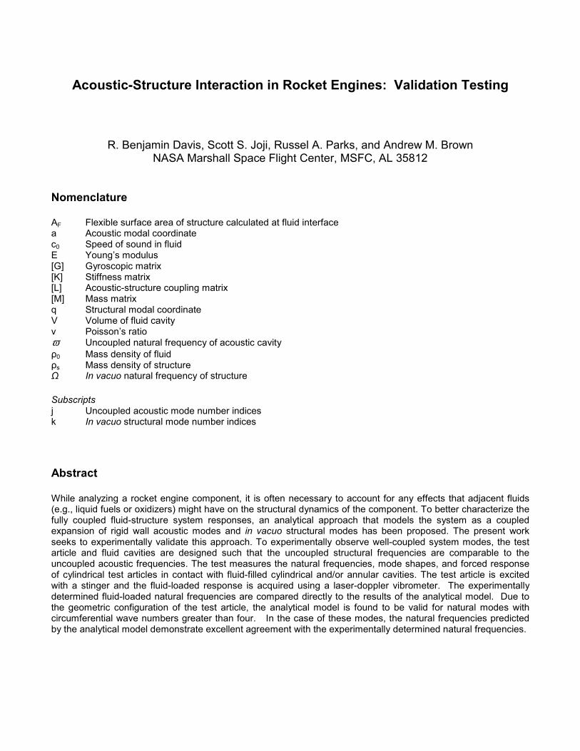
In an effort to characterize the system natural frequencies, modes, and forced response of fluid-loaded rocket engine components, an analytical approach has been proposed [1]. This approach is based on the acoustoelasticity theory developed by Dowell, et al. [2] which models an acoustic-structure system as coupled expansion of rigid wall acoustic modes and in vacuo structural modes. Ref. [3] applies this approach to geometries common to liquid rocket engines. Specifically, Ref. [3] considers cylindrical shells fully coupled to cylindrical and/or annular cavities filled with acoustic fluid. Figure 1 is a schematic of such as system.
Figure 1: Schematic of fluid-structure system under consideration
The present work considers an experimental configuration designed to resemble the system shown in Figure 1. The experimental results are compared to those calculated by the analytical approach proposed in Ref. [1]. The experimental results are also compared to results generated from a fully coupled acoustic-structure finite element model. The following three sections discuss the analytical, finite element, and experimental approaches. The final two sections of this paper present the results of three different approaches and discuss any relevant conclusions.
II. Analytical Approach The equations modeling a flexible structure coupled to an interior enclosed acoustic fluid take the following form
[ ] [ ] [ ]
=
+
+
0
0
k
j
k
j
k
j
q
aK
q
aG
q
aM
&
&
&&
&&, (1)
where
[ ] [ ] [ ][ ] [ ]
Ω=
−=
=
2
2
0
2
0
0
0
0
0
0
0
kk
jj
T
jkF
jkF
k
j
M
VMK
LA
LcAG
M
VMM
ϖρ
.
The [Ljk] matrices shown here consist of coupling coefficients corresponding to individual pairs of uncoupled acoustic and structural modes. Each coupling coefficient can be interpreted as a measure of the spatial similarity between a given modal pair. Eqs. (1) correspond to an unforced, undamped system of unspecified geometry. Ref. [3] details how Eqs. (1) can be written for the geometry depicted by Figure 1. Ref. [3] further explains how this system of equations can be solved when damping and forcing terms are applied. In the analytical approach employed here, the in vacuo frequencies and mode shapes for a clamped-free cylindrical shell are calculated with a procedure presented by Callahan and Baruh [4]. This procedure efficiently solves the Junger and Feit cylindrical shell equations [5] for common boundary conditions. The uncoupled acoustic frequencies and modes for cylindrical and annular fluid-filled cavities are calculated using standard formulae that can be found in (or derived with the aid of) many standard acoustics text (see e.g., Blackstock [6]).
III. Finite Element Model
Commercial finite element software packages such as ANSYS and NASTRAN have the built-in capabilities to solve acoustic-structure interaction problems like the one considered here. These capabilities (often called fluid-structure interaction (FSI) solutions) can be challenging to implement and are often computationally expensive. An analytical approach, such as the one described in Section II, largely avoids such difficulties. Furthermore, for cases in which complex geometries necessitate a finite element approach, an analytical solution affords the analyst the physical insight necessary to interpret and verify the finite element results. While the intent of this work is to validate the analytical approach presented in [1], an FSI finite element model of the test article was also created. This model serves as additional validation of the analytical approach. Additionally, after the fabrication of the test article, it was determined that certain modes are dominated by motion in the base of the test article. Since the geometric model used with the analytical approach considers only the cylindrical portion of the test article, these modes are not captured by the analytical calculations. The finite element model thus enables the calculation of coupled frequencies corresponding to these base-dominated modes.
IV. Experimental Approach
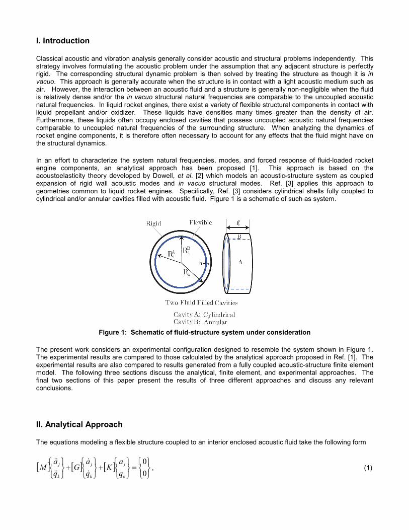
A series of modal tests and sine sweeps were performed on the test article shown in Figure 2. The test article is a 0.163” thick cylindrical shell with a mean radius of 4.382” and a length of 2.700”. The shell consists of steel (E = 29,000 psi, ρs= 0.283 lb/in
3, ν = 0.30) and is welded to a large base also made of steel. A ridge was machined
into the base of the test article in order to accommodate a 0.549” thick acrylic tank. The tank has a mean radius of 6.060” and a length of 3.704”. An acrylic lid was machined and fastened to the tank with six screws spaced around the circumference. The design of the experimental set-up allows for the test article to be in contact with cylindrical and/or annular fluid-filled cavities. Ethyl alcohol (c0= 3,960 ft/s, ρ0= 0.0285 lb/in
3) was used as the fluid
in all tests. Ethyl alcohol was chosen because it can be handled safely and because it has a density that is bounded by those of liquid hydrogen and liquid oxygen. To simulate acoustically rigid boundary conditions at the interface between the lid and the fluid, spacer plates were machined and attached to the underside of the lid. This ensured uniform contact between the fluid and the lid. A small clearance gap was left between the top of the test article and the spacer plates. This ensured a free structural boundary condition at the top of the test article. The entire experimental set-up (i.e., the test article, the acrylic tank, and the base) was assembled and placed on two large foam blocks used to simulate free-free boundary conditions at the bottom of the steel base.
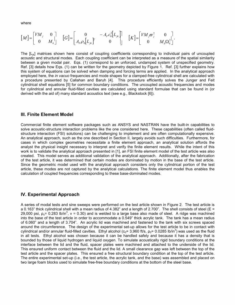
Before introducing any fluid to the system, a modal impact test was conducted on the test structure both with and without the acrylic tank. Each measurement location required five averages with a frequency span of 0 to 6,400 Hz and 8,192 lines of resolution. The test was designed to characterize the responses of the test article and the acrylic tank. The primary measurements were recorded along the top and center of both the test article and tank. It was determined that the presence of the acrylic tank had little influence on the natural frequencies and modes of the steel test article. Consequently, the analytical and finite element models developed here do not explicitly model the acrylic tank. Impact testing was only practical for the dry configurations. In the fluid-filled configurations, the test article was excited with a stinger. The presence of the acrylic lid and the fluid made it impossible to attach an accelerometer to the metal test article. Instead, a laser vibrometer was used to measure the response of the test article. Initially, the scanning features of the vibrometer were used to scan roughly one third of the structure. This configuration was adequate for determining low nodal diameter mode shapes, but modes with relatively high numbers of nodal diameters could not be distinguished. To remedy this deficiency, the laser vibrometer was subsequently configured in point-to-point mode. The vibrometer was physically moved or adjusted to measure single points 10° apart along the top of the test article (a representative image of the vibrometer set-up can be seen in Figure 3). For an approximately 30° sector of the test article, the stinger set-up blocked the path of the laser. It was therefore not possible to measure points around the entire circumference of the test article. Nevertheless, the available measurement points did allow for a reasonable determination of the mode shapes. The stinger itself was not modeled in either the analytical or the finite element approaches. Thus, the mass loading effects of the stinger are a potential source of error in the results. However, these effects were largely mitigated by placing the stinger as close to the base of the cylindrical portion of the test article as possible. Evaporation of the alcohol was observed to cause shifts in some of the resonant frequencies of the fluid structure system. Consequently, the frequency response at each measurement point was compared to a baseline response. If significant frequency shifts were observed at any point, the fluid cavities were topped-off with additional fluid and the response at the given was measured a second time. This topping-off of the cavity with additional fluid was found to be an effective means of removing any frequency shifts.
Figure 2: Experimental configuration with stinger in place
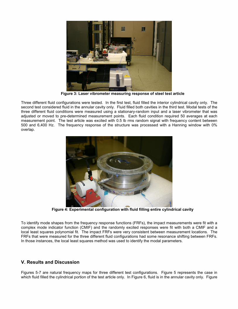
Figure 3: Laser vibrometer measuring response of steel test article
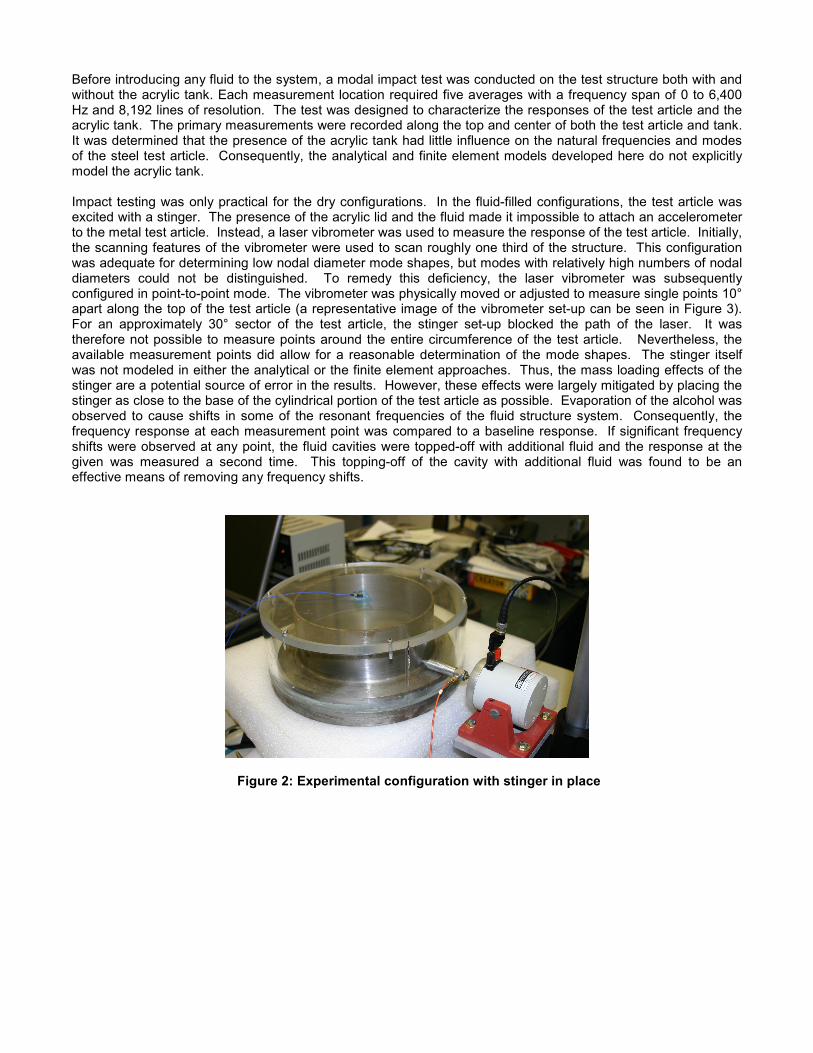
Three different fluid configurations were tested. In the first test, fluid filled the interior cylindrical cavity only. The second test considered fluid in the annular cavity only. Fluid filled both cavities in the third test. Modal tests of the three different fluid conditions were measured using a stationary-random input and a laser vibrometer that was adjusted or moved to pre-determined measurement points. Each fluid condition required 50 averages at each measurement point. The test article was excited with 0.5 lb rms random signal with frequency content between 500 and 6,400 Hz. The frequency response of the structure was processed with a Hanning window with 0% overlap.
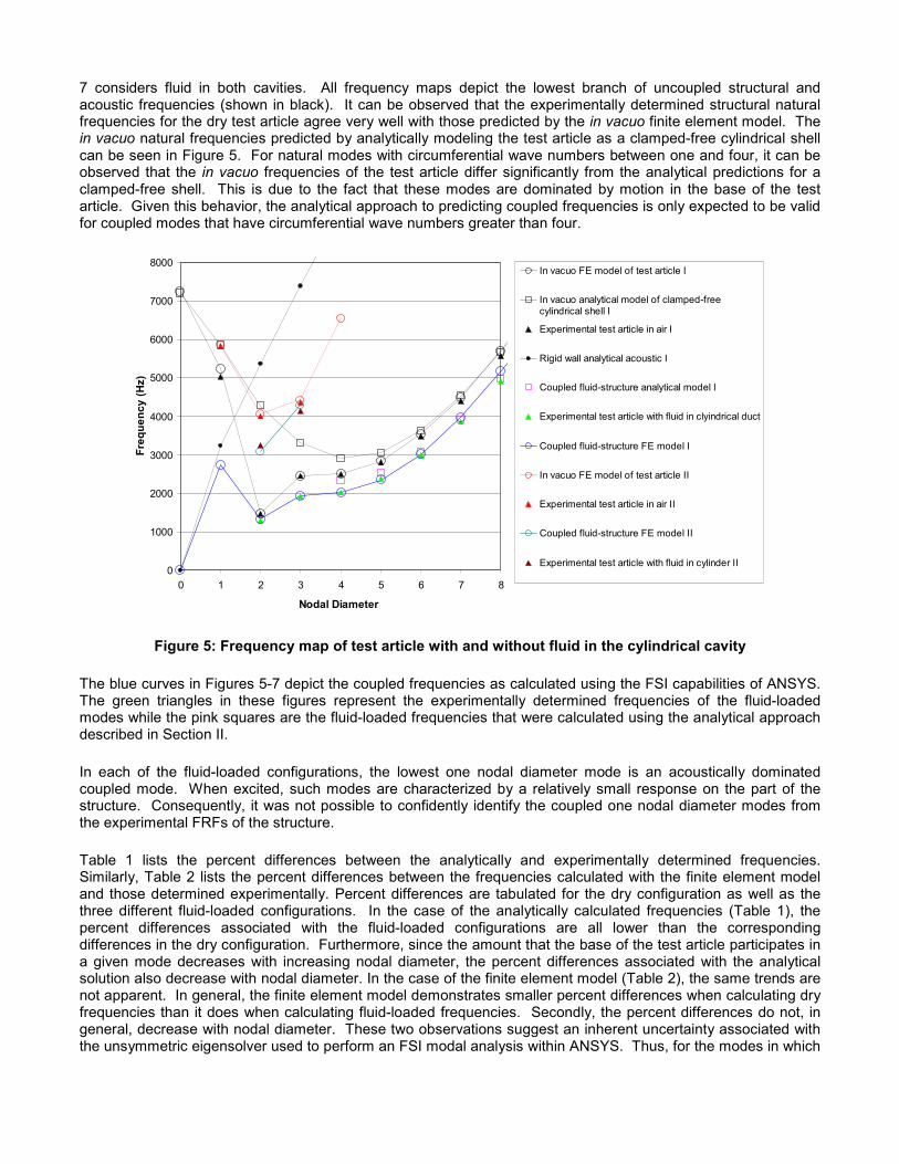
Figure 4: Experimental configuration with fluid filling entire cylindrical cavity
To identify mode shapes from the frequency response functions (FRFs), the impact measurements were fit with a complex mode indicator function (CMIF) and the randomly excited responses were fit with both a CMIF and a local least squares polynomial fit. The impact FRFs were very consistent between measurement locations. The FRFs that were measured for the three different fluid configurations had some resonance shifting between FRFs. In those instances, the local least squares method was used to identify the modal parameters.
V. Results and Discussion
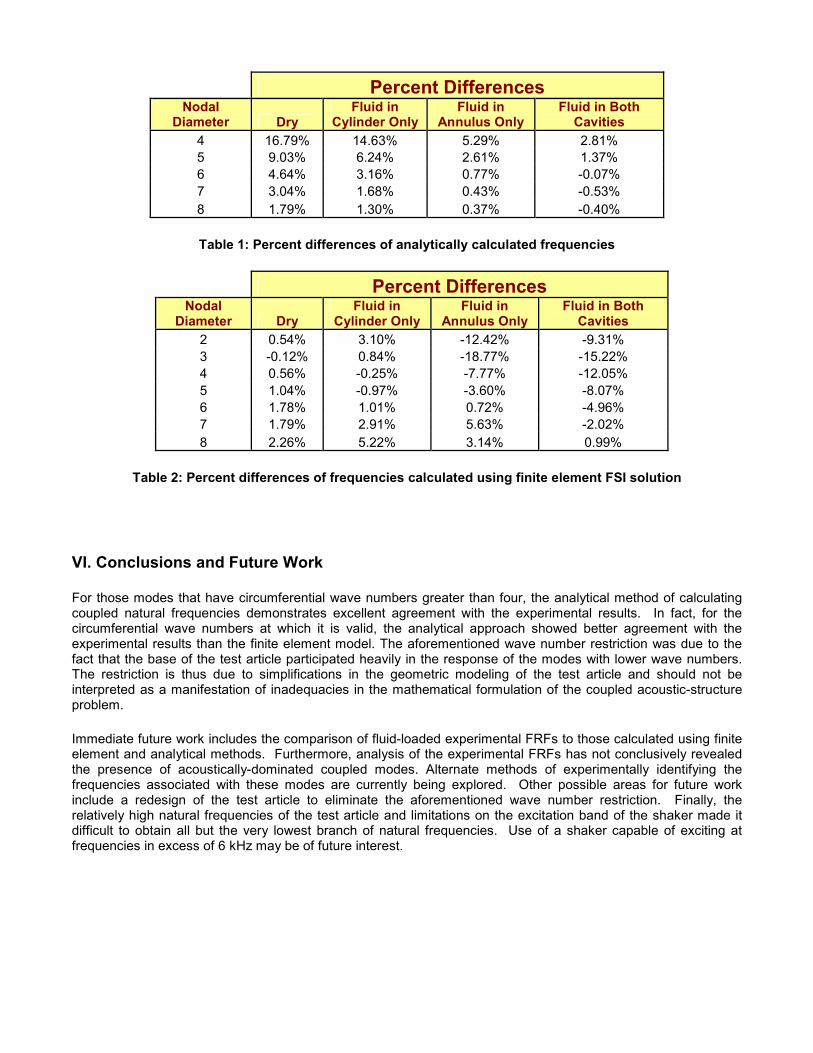
Figures 5-7 are natural frequency maps for three different test configurations. Figure 5 represents the case in which fluid filled the cylindrical portion of the test article only. In Figure 6, fluid is in the annular cavity only. Figure
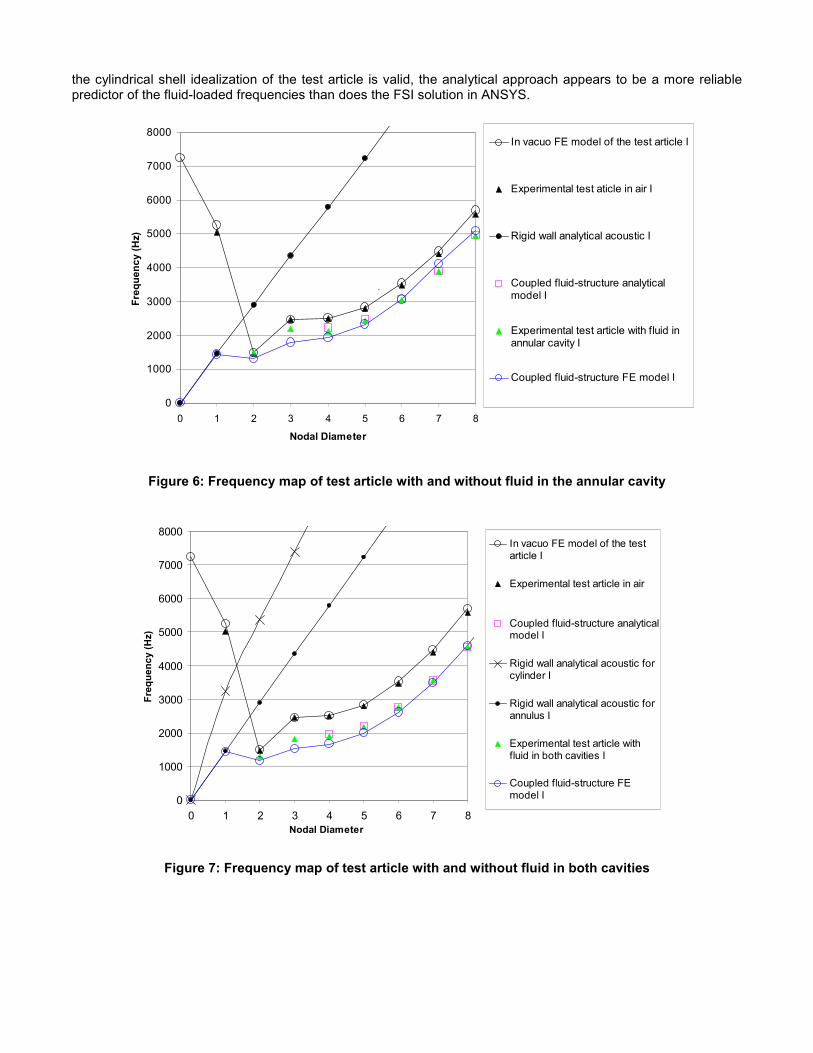
7 considers fluid in both cavities. All frequency maps depict the lowest branch of uncoupled structural and acoustic frequencies (shown in black). It can be observed that the experimentally determined structural natural frequencies for the dry test article agree very well with those predicted by the in vacuo finite element model. The in vacuo natural frequencies predicted by analytically modeling the test article as a clamped-free cylindrical shell can be seen in Figure 5. For natural modes with circumferential wave numbers between one and four, it can be observed that the in vacuo frequencies of the test article differ significantly from the analytical predictions for a clamped-free shell. This is due to the fact that these modes are dominated by motion in the base of the test article. Given this behavior, the analytical approach to predicting coupled frequencies is only expected to be valid for coupled modes that have circumferential wave numbers greater than four.
0
1000
2000
3000
4000
5000
6000
7000
8000
0 1 2 3 4 5 6 7 8
Nodal Diameter
Fre
quency (H
z)
In vacuo FE model of test article I
In vacuo analytical model of clamped-freecylindrical shell I
Experimental test article in air I
Rigid wall analytical acoustic I
Coupled fluid-structure analytical model I
Experimental test article with fluid in clyindrical duct
Coupled fluid-structure FE model I
In vacuo FE model of test article II
Experimental test article in air II
Coupled fluid-structure FE model II
Experimental test article with fluid in cylinder II
Figure 5: Frequency map of test article with and without fluid in the cylindrical cavity
The blue curves in Figures 5-7 depict the coupled frequencies as calculated using the FSI capabilities of ANSYS. The green triangles in these figures represent the experimentally determined frequencies of the fluid-loaded modes while the pink squares are the fluid-loaded frequencies that were calculated using the analytical approach described in Section II.
In each of the fluid-loaded configurations, the lowest one nodal diameter mode is an acoustically dominated coupled mode. When excited, such modes are characterized by a relatively small response on the part of the structure. Consequently, it was not possible to confidently identify the coupled one nodal diameter modes from the experimental FRFs of the structure.
Table 1 lists the percent differences between the analytically and experimentally determined frequencies. Similarly, Table 2 lists the percent differences between the frequencies calculated with the finite element model and those determined experimentally. Percent differences are tabulated for the dry configuration as well as the three different fluid-loaded configurations. In the case of the analytically calculated frequencies (Table 1), the percent differences associated with the fluid-loaded configurations are all lower than the corresponding differences in the dry configuration. Furthermore, since the amount that the base of the test article participates in a given mode decreases with increasing nodal diameter, the percent differences associated with the analytical solution also decrease with nodal diameter. In the case of the finite element model (Table 2), the same trends are not apparent. In general, the finite element model demonstrates smaller percent differences when calculating dry frequencies than it does when calculating fluid-loaded frequencies. Secondly, the percent differences do not, in general, decrease with nodal diameter. These two observations suggest an inherent uncertainty associated with the unsymmetric eigensolver used to perform an FSI modal analysis within ANSYS. Thus, for the modes in which
the cylindrical shell idealization of the test article is valid, the analytical approach appears to be a more reliable predictor of the fluid-loaded frequencies than does the FSI solution in ANSYS.
0
1000
2000
3000
4000
5000
6000
7000
8000
0 1 2 3 4 5 6 7 8
Nodal Diameter
Fre
quency (H
z)
In vacuo FE model of the test article I
Experimental test aticle in air I
Rigid wall analytical acoustic I
Coupled fluid-structure analyticalmodel I
Experimental test article with fluid inannular cavity I
Coupled fluid-structure FE model I
`
Figure 6: Frequency map of test article with and without fluid in the annular cavity
0
1000
2000
3000
4000
5000
6000
7000
8000
0 1 2 3 4 5 6 7 8
Nodal Diameter
Fre
quency (H
z)
In vacuo FE model of the testarticle I
Experimental test article in air
Coupled fluid-structure analyticalmodel I
Rigid wall analytical acoustic forcylinder I
Rigid wall analytical acoustic forannulus I
Experimental test article withfluid in both cavities I
Coupled fluid-structure FEmodel I
Figure 7: Frequency map of test article with and without fluid in both cavities
Percent Differences Nodal
Diameter Dry Fluid in
Cylinder Only Fluid in
Annulus Only Fluid in Both
Cavities
4 16.79% 14.63% 5.29% 2.81%
5 9.03% 6.24% 2.61% 1.37%
6 4.64% 3.16% 0.77% -0.07%
7 3.04% 1.68% 0.43% -0.53%
8 1.79% 1.30% 0.37% -0.40%
Table 1: Percent differences of analytically calculated frequencies
Percent Differences Nodal
Diameter Dry Fluid in
Cylinder Only Fluid in
Annulus Only Fluid in Both
Cavities
2 0.54% 3.10% -12.42% -9.31%
3 -0.12% 0.84% -18.77% -15.22%
4 0.56% -0.25% -7.77% -12.05%
5 1.04% -0.97% -3.60% -8.07%
6 1.78% 1.01% 0.72% -4.96%
7 1.79% 2.91% 5.63% -2.02%
8 2.26% 5.22% 3.14% 0.99%
Table 2: Percent differences of frequencies calculated using finite element FSI solution
VI. Conclusions and Future Work
For those modes that have circumferential wave numbers greater than four, the analytical method of calculating coupled natural frequencies demonstrates excellent agreement with the experimental results. In fact, for the circumferential wave numbers at which it is valid, the analytical approach showed better agreement with the experimental results than the finite element model. The aforementioned wave number restriction was due to the fact that the base of the test article participated heavily in the response of the modes with lower wave numbers. The restriction is thus due to simplifications in the geometric modeling of the test article and should not be interpreted as a manifestation of inadequacies in the mathematical formulation of the coupled acoustic-structure problem.
Immediate future work includes the comparison of fluid-loaded experimental FRFs to those calculated using finite element and analytical methods. Furthermore, analysis of the experimental FRFs has not conclusively revealed the presence of acoustically-dominated coupled modes. Alternate methods of experimentally identifying the frequencies associated with these modes are currently being explored. Other possible areas for future work include a redesign of the test article to eliminate the aforementioned wave number restriction. Finally, the relatively high natural frequencies of the test article and limitations on the excitation band of the shaker made it difficult to obtain all but the very lowest branch of natural frequencies. Use of a shaker capable of exciting at frequencies in excess of 6 kHz may be of future interest.
VII. References
[1] R.B. Davis, Techniques to Assess Acoustic-Structure Interaction in Liquid Rocket Engines. Ph.D. thesis, Duke University, Durham, NC, USA, 2008.
[2] E. H. Dowell, G. F. Gorman III, and D. A. Smith. Acoustoelasticity: General theory, acoustic natural modes and forced response to sinusoidal excitation including comparisons with experiment. Journal of Sound and Vibration, 52(4): 519-542, 1977.
[3] R.B. Davis, L.N. Virgin, and A.M. Brown. Cylindrical shell submerged in bounded acoustic media: A modal approach. AIAA Journal, 46(3):752-763, 2008.
[4] J. Callahan and H. Baruh. A closed-form solution procedure for circular cylindrical shell vibrations. International Journal of Solids and Structures, 36:2973-3013, 1999.
[5] M. C. Junger and D. Feit. Sound, Structures and Their Interaction. Acoustical Society of America, Melville, NY, 1993.
[6] D. T. Blackstock. Fundamentals of Physical Acoustics. Wiley, New York, NY 2000.


