Embed Size (px)
Citation preview
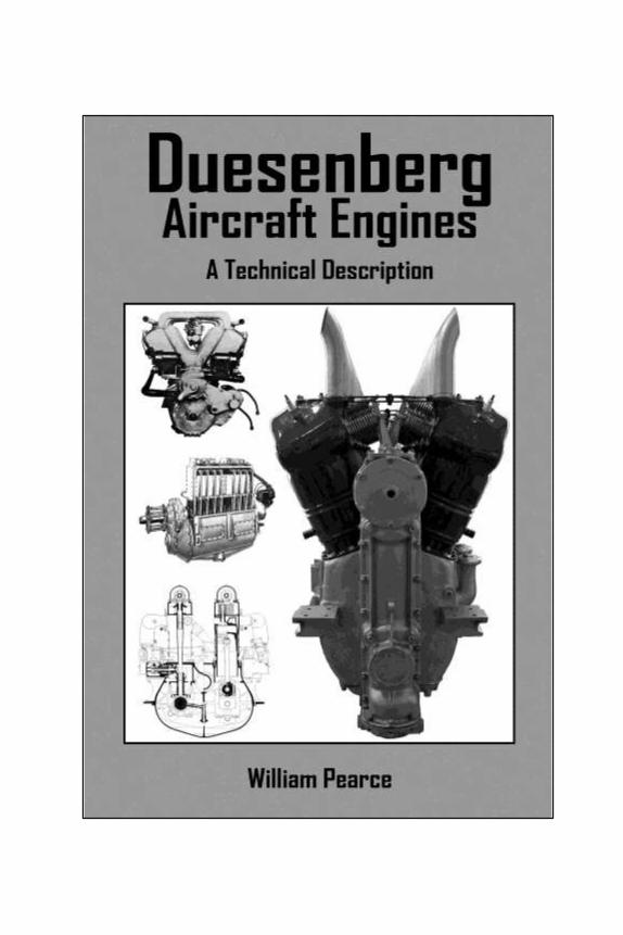

Duesenberg Aircraft Engines
A Technical Description
William Pearce

This copy of Duesenberg Aircraft Engines: A Technical Description has
been prepared especially for the Aircraft Engine Historical Society. A printed version is available through Old Machine Press or at
Amazon.com.
Old Machine Press Los Osos, CA
www.oldmachinepress.com
Copyright © 2012 William Pearce
All rights reserved.
The information in this work is true and complete to the best of our
knowledge. However, all information is presented without any guarantee
on the part of the Author or Publisher, who also disclaim any liability incurred in connection with the use of the information.
All trademarks, trade names, model names and numbers, and other product designations referred to herein are the property of their
respective owners and are used solely for identification purposes. This
work is a publication of Old Machine Press and has not been licensed, approved, sponsored, or endorsed by any other person or entity.
Revision 04172012 - AEHS
On the cover:
Upper left—Rear view of the Duesenberg V-12 aircraft engine.
Middle left—The 16-valve, four-cylinder Duesenberg aircraft engine.
Lower left—Sectional end view of the Duesenberg-built King-Bugatti aircraft engine.
Right—Rear view of the Duesenberg Model H aircraft engine (Martt
Clupper photo via AirPigz, www.airpigz.com).
Tittle page:
The Gallaudet D-1: perhaps the first aircraft to fly with Duesenberg engines.
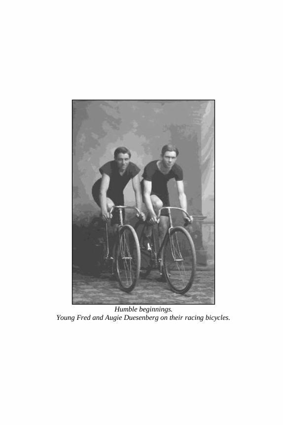
Humble beginnings.
Young Fred and Augie Duesenberg on their racing bicycles.
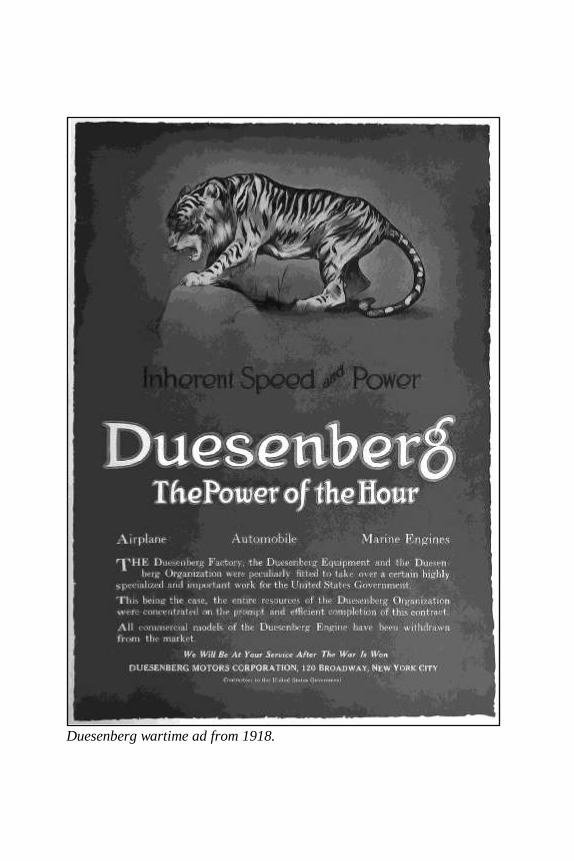
Duesenberg wartime ad from 1918.
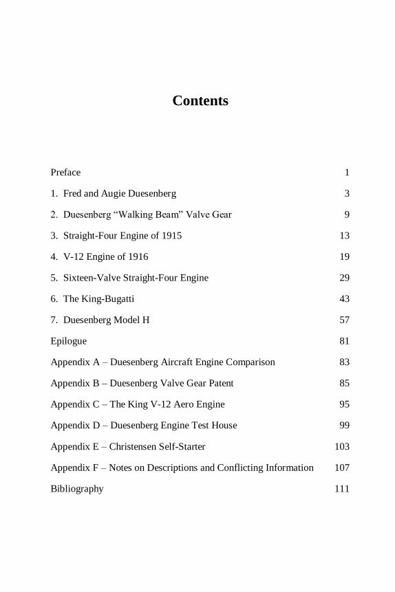
Contents
Preface 1
1. Fred and Augie Duesenberg 3
2. Duesenberg “Walking Beam” Valve Gear 9
3. Straight-Four Engine of 1915 13
4. V-12 Engine of 1916 19
5. Sixteen-Valve Straight-Four Engine 29
6. The King-Bugatti 43
7. Duesenberg Model H 57
Epilogue 81
Appendix A – Duesenberg Aircraft Engine Comparison 83
Appendix B – Duesenberg Valve Gear Patent 85
Appendix C – The King V-12 Aero Engine 95
Appendix D – Duesenberg Engine Test House 99
Appendix E – Christensen Self-Starter 103
Appendix F – Notes on Descriptions and Conflicting Information 107
Bibliography 111

1
Preface
This book began as a quest to consolidate information on the Duesenberg
Model H aircraft engine and eventually evolved to include all the Duesenberg aircraft engines. Information on these engines is hard to
come by, for while the Duesenberg automobile became legendary,
Duesenberg aircraft engines did not advance aviation or even the art of
aircraft engines. But these engines did possess unique features and are well worth being remembered.
My interest in the Duesenberg Model H began as a result of Martt Clupper’s article on the engine. I found the article on his website,
www.airpigz.com, and the photos in his article made me want to know
more about this masterpiece of an engine from a bygone era.
My internet searches did not uncover much more than what I had already
read about the engine. I turned to my ever-expanding bookshelf, and I
went through several engine books from the 1920s. I found much more information on the Model H, but to my dismay, I also found contra-
dictions and closed the books with many questions unanswered. That
was when I decided to get serious with my research and to put together all I could find on the Model H. I knew others were interested in this
engine and that it would be very helpful to have most of the information
in one place. I soon realized that the Model H owed much to the previous Duesenberg aircraft engines, so I included them as part of its history.
While searching for more about these earlier engines, I realized that
information on them was even harder to find, so I decided to include
everything I could on all the Duesenberg designed or manufactured aircraft engines.
Admittedly, everything contained in this work exists in print somewhere else. Even so, I’m confident that much of the information will be new to
the reader, given the rarity of the subject. I have compiled the
information from old and obscure sources, and I attempted to clarify
Duesenberg Aircraft Engines
2
descriptions and contradictory information (see Appendix F). I have done
my best to make sure the information is complete and correct; any errors or omissions are entirely my own.
I would like to thank Martt Clupper for his photos and story of the
Duesenberg Model H, which were the catalyst for this work; the Aircraft Engine Historical Society (www.enginehistory.com) for everything they
do; Tom Fey and Kim McCutcheon for their valuable and appreciated
advice; and my wife, Katie, for her hard work helping me edit this book.
William Pearce [email protected]
January 2012
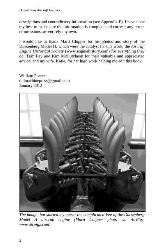
The image that started my quest: the complicated Vee of the Duesenberg
Model H aircraft engine (Martt Clupper photo via AirPigz, www.airpigz.com).
3
1. Fred and Augie Duesenberg
Frederick and August Duesenberg were born in Kirchheide, Germany,
Frederick on December 6, 1876 and August on December 12, 1879. In 1885, they immigrated to the United States with their mother and other
siblings. They joined their older brother, already in the U.S., and settled
in Rockford, Iowa. Fred began building and racing bicycles with Augie
as his able assistant. While the self-taught engineers shared their talents, Fred was more of the genius designer, and Augie was the one who
brought the designs to life. The brothers’ interest in bicycles soon shifted
to building and racing motorcycles. By the late 1890, both brothers were operating bicycle and motorcycle repair shops, Fred still in Rockford,
and Augie 40 miles away in Garner, Iowa.
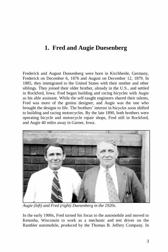
Augie (left) and Fred (right) Duesenberg in the 1920s.
In the early 1900s, Fred turned his focus to the automobile and moved to
Kenosha, Wisconsin to work as a mechanic and test driver on the
Rambler automobile, produced by the Thomas B. Jeffery Company. In

Duesenberg Aircraft Engines
4
1902, the Thomas B. Jeffery Company was the second largest automo-
bile manufacturer in the world.
But Fred had greater aspirations and returned home in 1904. Together, he
and Augie set up a shop in Des Moines, Iowa and began building their
first automobile, known as the Marvel. Powered by a 24 hp, two-cylinder engine of their own design, the auto caught the eye of Edward Mason, a
local attorney, who provided funding for its production. Now known as
the Mason Runabout, the vehicle made its commercial debut in 1906 and was marketed as the fastest and strongest two-cylinder car in America.
The Mason Runabout was the start of these mechanically gifted brothers
making a name for themselves building autos and engines that were considered some of the very best of their time.
Fred Maytag, of washing machine fame, bought 60 percent of the Mason
Automobile Company in 1910. The company was renamed the Maytag-Mason Motor Company and moved to Waterloo, Iowa. Maytag quickly
lost interest in automobile manufacturing, and Mason moved the brothers
back to Des Moines, where they worked out of a garage at a car dealer-ship. In 1912, Mason supported the brothers’ auto racing endeavors.
In 1913, the Duesenberg brothers founded the Duesenberg Motor Company, Inc. in St. Paul, Minnesota to build race engines and cars
under their own name. Fred and Augie became famous designing and
building racing engines for automobiles and boats, and the Duesenberg
name went on to become a legend.
Before he was America’s top scoring ace of World War I, Eddie
Rickenbacker was a manager and a race car driver for the Duesenberg Company. In 1914, Rickenbacker drove a Duesenberg to a 10th place
finish in the Indianapolis 500, with another Duesenberg finishing 12th.
By 1916, it was estimated that 60 percent of race cars were powered by
Duesenberg engines, a rather inconceivable figure.
In early 1917, Duesenberg Motor Company and the Loew-Victor Engine
Company combined to form the Duesenberg Motors Corporation. The new corporation concentrated on manufacturing engines for marine, auto,
and aviation use. At the time, Loew-Victor Co. was producing Fred
Duesenberg designed high-speed marine engines and had the experience and equipment to produce other Duesenberg engines. The new company
was headquartered in New York City, New York, but production took
place in Elizabeth, New Jersey. In May of 1918, the Duesenberg
Corporation completed construction of a state-of-the-art engine test

1. Fred and Augie Duesenberg
5
house next to their plant in Elizabeth, NJ. This test house was believed to
be the world’s largest engine test house at the time (see Appendix D).
Eddie Rickenbacker in his Duesenberg Indianapolis 500 racer for 1914.
At the end of World War I, Duesenberg ceased building aviation and
marine engines. The company was again reorganized, and the facilities in
New Jersey were sold. In 1920, the Duesenberg Automobile and Motors Company, Inc. was founded with a new headquarters and factory in
Indianapolis, Indiana. Fred and Augie Duesenberg were now focused on
the production of passenger cars, their new straight-eight engine, and building racing cars and engines. Duesenberg’s first passenger car, the
Model A, went into production in 1921.
Tommy Milton running at Daytona Beach in 1920 where he recorded a
run of 156.046 mph in the twin straight-eight powered Duesenberg.
Duesenberg Aircraft Engines
6
In the 1920s the Duesenberg automobile really hit its stride. At Tommy
Milton’s suggestion, the brothers built a car around two straight-eight Duesenberg engines. On April 27, 1920, Milton drove the twin-engined
Duesenberg at Daytona Beach, Florida and set the American land speed
record at 156.046 mph. The record stood until 1927. Duesenberg autos
won seven of the top ten places at Indy in 1920; Le Mans in 1921; and Indy in 1922 (powered by a Miller engine), 1924, 1925, and 1927.
During this time period Duesenberg introduced a centrifugal super-
charger for its straight-eight engine, with the help of Dr. Sanford A. Moss, and numerous records were set by Duesenberg-powered machines.
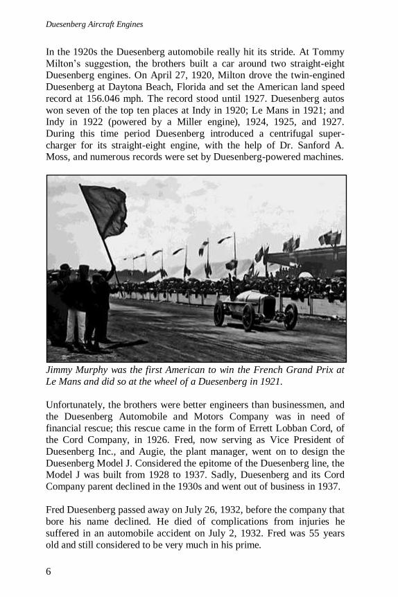
Jimmy Murphy was the first American to win the French Grand Prix at
Le Mans and did so at the wheel of a Duesenberg in 1921.
Unfortunately, the brothers were better engineers than businessmen, and
the Duesenberg Automobile and Motors Company was in need of
financial rescue; this rescue came in the form of Errett Lobban Cord, of the Cord Company, in 1926. Fred, now serving as Vice President of
Duesenberg Inc., and Augie, the plant manager, went on to design the
Duesenberg Model J. Considered the epitome of the Duesenberg line, the Model J was built from 1928 to 1937. Sadly, Duesenberg and its Cord
Company parent declined in the 1930s and went out of business in 1937.
Fred Duesenberg passed away on July 26, 1932, before the company that
bore his name declined. He died of complications from injuries he
suffered in an automobile accident on July 2, 1932. Fred was 55 years
old and still considered to be very much in his prime.

1. Fred and Augie Duesenberg
7
Augie continued to work his magic as a designer and mechanic, aiding
several successful speed record attempts. The pinnacle of Augie’s post-Duesenberg career was designing and building Ab Jenkins’ Curtiss
Conqueror powered Mormon Meteor III that Jenkins drove to 26
endurance speed records, some of which still stand today. After World
War II, Augie attempted to bring back the Duesenberg automobile, but to no avail. He passed away from a heart attack on January 18, 1955.
Ab Jenkins (left) shakes hands with Augie Duesenberg (right) in front of
the Curtiss Conqueror (V-1570) powered Mormon Meteor III at the
Indianapolis Speedway in 1938.
Today, Duesenberg autos are sought after by classic car collectors and
fetch millions on the auction block; they are the absolute pinnacle of American luxury from the 1920s and 1930s. In August 2011, the very
special 1931 Model J Whitell Coupe sold for $10.34 million at Pebble
Beach, California, a record for an American car at auction.
Although the Duesenberg auto is famous, their aircraft engines are
relatively unknown. In 1915, aviation was in its exciting infancy and war
was spreading across Europe. It was clear that the airplane would play a part in the war and an even larger role in transportation. In those days
more than ever, the engine was the heart of the aircraft. It was in this
dynamic time that the Duesenbergs turned their attention and expertise to aircraft engines, with Fred leading the design and development.
Duesenberg Aircraft Engines
8
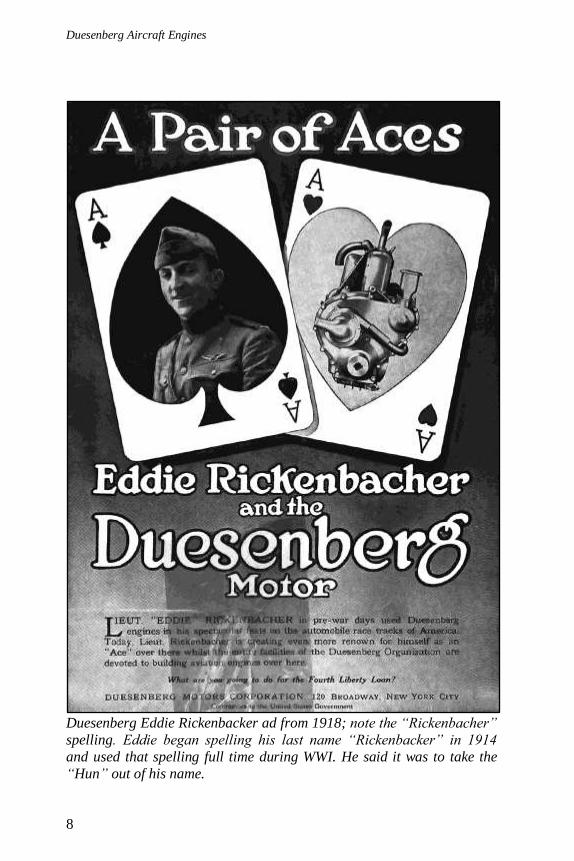
Duesenberg Eddie Rickenbacker ad from 1918; note the “Rickenbacher”
spelling. Eddie began spelling his last name “Rickenbacker” in 1914
and used that spelling full time during WWI. He said it was to take the
“Hun” out of his name.
9
2. Duesenberg “Walking Beam” Valve Gear
One of the most unique characteristics of the Duesenberg engines was
their valve gear. Fred and Augie Duesenberg originally described this valve gear in their Internal Combustion Engine patent application of
April 1913. However, in August 1914 the valve gear was divided from
the original patent and filed separately, being granted United States
patent 1,244,481 in October 1917 (see Appendix B). In the Valve Gear patent, Fred and Augie Duesenberg cited the improvements of their valve
system for use in internal combustion engines over the inefficiencies of
then-current valve systems in use. They claimed that standard valve systems seated poorly, were prone to sticking open due to heat and lack
of lubrication, and resulted in poor combustion.
The Duesenberg valve gear used horizontal valves that were
perpendicular to the cylinder axis and opened into a small, rectangular
clearance space above the cylinders. This space extended the combustion
chamber above the piston and ran parallel with the crankshaft. The spark plug was positioned on the opposite side of this space to achieve near
instant ignition of the air/fuel mixture, resulting in improved combustion
and efficiency. In essence, this configuration gave a stratified charge to the cylinder. The rich air/fuel mixture was ignited by the spark plug
positioned near the intake valve in the small combustion space. The
flame front then propagated down to the areas of leaner air/fuel mixture throughout the rest of the combustion chamber.
The cylinders and head were a single casting, and large, threaded,
removable plugs were inserted into ports opposite the valves in the small combustion chamber space. Once the plugs were removed, the intake and
exhaust valves could be inserted or removed through these ports. In
addition, the ports allowed the inspection and cleaning of the cylinders and piston crown.
Duesenberg Aircraft Engines
10
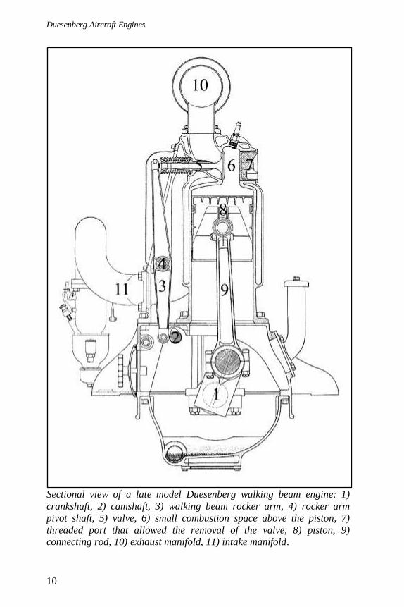
Sectional view of a late model Duesenberg walking beam engine: 1)
crankshaft, 2) camshaft, 3) walking beam rocker arm, 4) rocker arm
pivot shaft, 5) valve, 6) small combustion space above the piston, 7)
threaded port that allowed the removal of the valve, 8) piston, 9) connecting rod, 10) exhaust manifold, 11) intake manifold.
2. Duesenberg “Walking Beam” Valve Gear
11
The valves were actuated by very long and large rocker arms,
colloquially referred to as “walking beams.” The rocker arms were actuated directly by a camshaft running along the engine block. A
hardened contact or roller was attached to the rocker arm where it came
into contact with the camshaft. The rocker arms were mounted on a
common shaft that ran the length of the cylinder block. Each rocker arm was offset on this shaft, creating a short side of the rocker arm and a long
side. The short side of the rocker arm was actuated by the camshaft, and
the long side of the arm actuated the valve. Camshaft movement on the short side was effectively multiplied on the long side. This enabled the
valves to be opened and closed instantly. Due to the length of the rocker
arm, the push on the valve was basically a straight line with little side thrust. The entire valve gear could be enclosed; this not only aided in
proper lubrication but also protected the valve gear and made it quieter.
The term “walking beams” comes from the visually similar walking beam drilling and pumping machinery first used in the 1800s, pre-
dominantly on oil rigs. In addition, many paddle wheel steamboats from
the United States were powered by walking beam engines, first intro-duced in the 1830s.
The Duesenbergs asserted that their valve gear was more reliable, durable, and efficient than the other systems in use at the time. The
valves seated better and allowed more efficient combustion. The entire
valve gear received good lubrication that reduced wear and heat,
subsequently increasing the life of the parts. At a time when exposed valves lubricated by grease cups were the norm, it is easy to see how the
Duesenberg valve gear was a definite step forward. The walking beam
side valves were used on all the Duesenberg-designed aircraft engines.
By the early 1920s, Fred and Augie Duesenberg had moved on to a more
conventional overhead camshaft valve gear. They sold the walking beam
engine production rights to the Rochester Motors Corporation of Rochester, New York.

Duesenberg Aircraft Engines
12
Duesenberg airplane engine ad from 1917.
13
3. Straight-Four Engine of 1915
In 1915, The Duesenberg brothers began to market their engines to
power aircraft. The first aircraft engines were slightly modified and lightened versions of the brothers’ automotive engines. The aircraft
engines were known as the Special A and the Special A3; they differed
only in their cylinder bore. Both were water-cooled, inline, monobloc,
four-cylinder engines with two valves per cylinder.
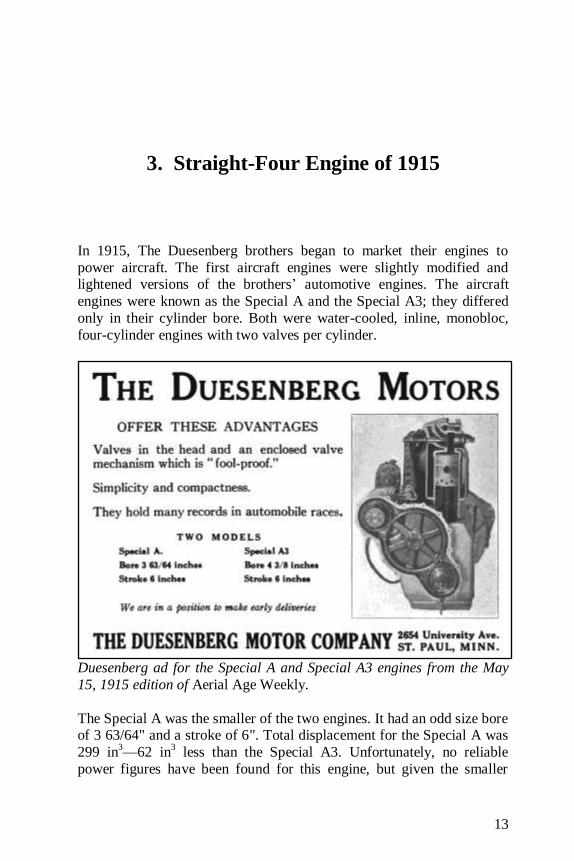
Duesenberg ad for the Special A and Special A3 engines from the May
15, 1915 edition of Aerial Age Weekly.
The Special A was the smaller of the two engines. It had an odd size bore of 3 63/64" and a stroke of 6". Total displacement for the Special A was
299 in3—62 in
3 less than the Special A3. Unfortunately, no reliable
power figures have been found for this engine, but given the smaller
Duesenberg Aircraft Engines
14
displacement, it can be assumed that the Special A was less powerful
than the Special A3 noted below.
With a 4 3/8" bore and 6" stroke, the larger Special A3 had a total
displacement of 361 in3, and produced 70 hp at 1,500 rpm, 80 hp at 2,000
rpm, and 85 hp at 2,220 rpm. It was claimed to achieve maximum power at 2,500 rpm, but no value has been found. However, most sources rate
the engine at 70 hp because 1,500 rpm was the most effective rpm setting
for this direct drive engine in an age of fixed-pitch propellers.
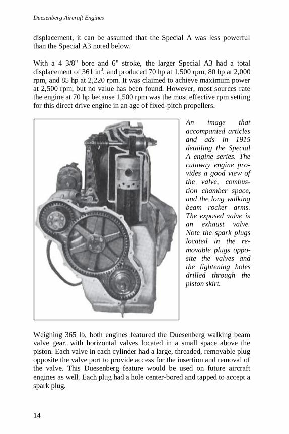
An image that
accompanied articles and ads in 1915
detailing the Special
A engine series. The
cutaway engine pro-vides a good view of
the valve, combus-
tion chamber space, and the long walking
beam rocker arms.
The exposed valve is an exhaust valve.
Note the spark plugs
located in the re-
movable plugs oppo-site the valves and
the lightening holes
drilled through the piston skirt.
Weighing 365 lb, both engines featured the Duesenberg walking beam valve gear, with horizontal valves located in a small space above the
piston. Each valve in each cylinder had a large, threaded, removable plug
opposite the valve port to provide access for the insertion and removal of the valve. This Duesenberg feature would be used on future aircraft
engines as well. Each plug had a hole center-bored and tapped to accept a
spark plug.
3. Straight-Four Engine of 1915
15
The tungsten valves were 2 3/16" in diameter, had a 2 1/16" throat
diameter, and a lift of 3/8". Exhaust was expelled from the top of the engine from ports above the exhaust valves. The center two cylinders had
their exhaust ports paired. The intake valves for adjacent cylinders were
located together so that the first two cylinders shared an intake runner,
and the last two cylinders shared an intake runner. These two runners were cast integral with the side of the engine block, between the
cylinders and the rocker arms. The runners joined together at the middle
of the engine to form a single intake that began at the engine’s side. Here, a manifold was attached to the outside of the engine to enable the
use of a single updraft carburetor.
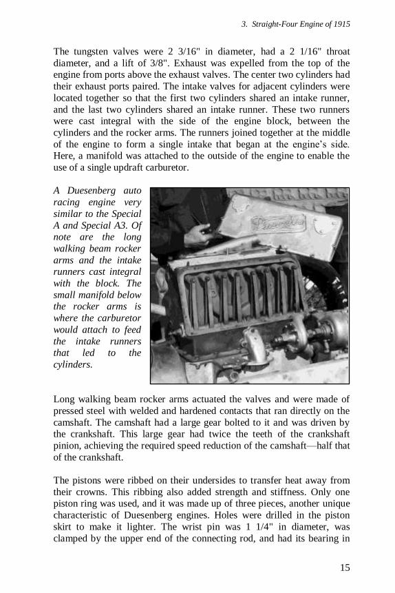
A Duesenberg auto
racing engine very
similar to the Special
A and Special A3. Of note are the long
walking beam rocker
arms and the intake runners cast integral
with the block. The
small manifold below the rocker arms is
where the carburetor
would attach to feed
the intake runners that led to the
cylinders.
Long walking beam rocker arms actuated the valves and were made of
pressed steel with welded and hardened contacts that ran directly on the
camshaft. The camshaft had a large gear bolted to it and was driven by the crankshaft. This large gear had twice the teeth of the crankshaft
pinion, achieving the required speed reduction of the camshaft—half that
of the crankshaft.
The pistons were ribbed on their undersides to transfer heat away from
their crowns. This ribbing also added strength and stiffness. Only one piston ring was used, and it was made up of three pieces, another unique
characteristic of Duesenberg engines. Holes were drilled in the piston
skirt to make it lighter. The wrist pin was 1 1/4" in diameter, was
clamped by the upper end of the connecting rod, and had its bearing in
Duesenberg Aircraft Engines
16
the piston. The wrist pins were bored out and tapered to the outer ends to
achieve maximum strength but minimum weight. They were case hard-ened, ground, and then polished. The connecting rods were 12" long and
made from heat treated chrome-nickel steel of I-beam construction. The
rod was held to the crankshaft by four 7/16" vanadium steel bolts.
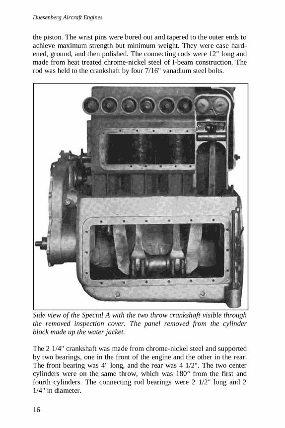
Side view of the Special A with the two throw crankshaft visible through
the removed inspection cover. The panel removed from the cylinder
block made up the water jacket.
The 2 1/4" crankshaft was made from chrome-nickel steel and supported
by two bearings, one in the front of the engine and the other in the rear.
The front bearing was 4" long, and the rear was 4 1/2". The two center cylinders were on the same throw, which was 180° from the first and
fourth cylinders. The connecting rod bearings were 2 1/2" long and 2
1/4" in diameter.
3. Straight-Four Engine of 1915
17
The engines used a combination of pressure and splash lubrication. Oil
was pressure fed directly to all bearings and to the rocker arm pivot shaft. The connecting rods, cylinders, and valves used splash lubrication. Two
oil pumps were utilized. The first pump supplied oil directly from the
main oil tank to the bearings. From the bearings, the oil drained into
troughs under the connecting rods for splash lubrication. The second oil pump was larger and took oil from the troughs and returned it to the tank.
The two spark plugs per cylinder were fired by a Bosch magneto, and fuel was provided by a Harry A. Miller Manufacturing Company (Miller)
carburetor. The crankcase was of the barrel type and had a 6" by 18"
access cover on each side.
Engine Specifications
Engine: Special A First Run: 1915
Type: Straight 4-cylinder, two valves per cylinder,
water-cooled, aircraft engine Displacement: 299 in
3
Bore: 3.984375"
Stroke: 6" Gear Reduction: None
Carburetion: One Miller updraft
Weight: 365 lb
Engine: Special A3
First Run: 1915 Type: Straight 4-cylinder, two valves per cylinder,
water-cooled, aircraft engine
Horsepower: 70 hp at 1,500 rpm, 85 hp at 2,220 rpm
Displacement: 361 in3
Bore: 4.375"
Stroke: 6"
BMEP: 102.4 psi at 1,500 rpm, 84.0 psi at 2,220 rpm Specific Weight: 5.21 lb/hp at 1,500 rpm, 4.29 lb/hp at 2,220 rpm
Specific Power: 0.19 hp/in3 at 1,500 rpm,
0.24 hp/in3 at 2,220 rpm
Gear Reduction: None
Carburetion: One Miller updraft
Weight: 365 lb

Duesenberg Aircraft Engines
18
Duesenberg Motors announcement of its reorganization from May 1917. Detailed in the announcement are the 16-valve, four-cylinder engine; the
Gallaudet D-1 seaplane; and the Lanzius L1 biplane with a drawing (see
section 5. Sixteen-Valve Straight-Four Engine on page 29).
19
4. V-12 Engine of 1916
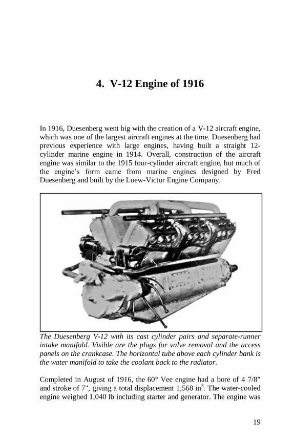
In 1916, Duesenberg went big with the creation of a V-12 aircraft engine,
which was one of the largest aircraft engines at the time. Duesenberg had previous experience with large engines, having built a straight 12-
cylinder marine engine in 1914. Overall, construction of the aircraft
engine was similar to the 1915 four-cylinder aircraft engine, but much of
the engine’s form came from marine engines designed by Fred Duesenberg and built by the Loew-Victor Engine Company.
The Duesenberg V-12 with its cast cylinder pairs and separate-runner intake manifold. Visible are the plugs for valve removal and the access
panels on the crankcase. The horizontal tube above each cylinder bank is
the water manifold to take the coolant back to the radiator.
Completed in August of 1916, the 60° Vee engine had a bore of 4 7/8"
and stroke of 7", giving a total displacement 1,568 in3. The water-cooled
engine weighed 1,040 lb including starter and generator. The engine was
Duesenberg Aircraft Engines
20
direct drive and generated 300 hp at 1,400 rpm and 350 hp at 1,800 rpm.
It was believed that the engine could develop 400 hp at 2,100 rpm.
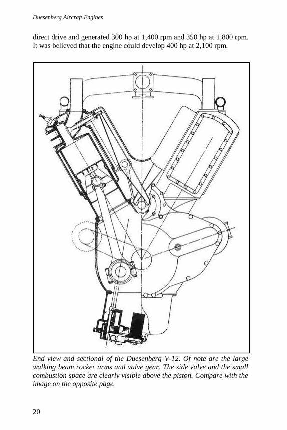
End view and sectional of the Duesenberg V-12. Of note are the large
walking beam rocker arms and valve gear. The side valve and the small
combustion space are clearly visible above the piston. Compare with the image on the opposite page.
4. V-12 Engine of 1916
21
As with the earlier four-cylinder aircraft engine, the V-12 had two side-
by-side valves per cylinder and used the walking beam valve gear actuated by the camshaft, all located in the Vee of the engine. Hardened
contacts were welded to the rocker arms and rode directly on the
camshaft. The camshaft ran in a trough in the Vee that accumulated oil
forced through the bearings. The cams dipped into this oil every revo-lution. The valve gear was housed in an aluminum, V-shaped cover that
sat between each opposite pair of cylinders and helped stiffen the engine.
As with the Special A engines, the valves could be removed through ports on the opposite side of the cylinder. These ports were sealed with
threaded plugs. The two spark plugs per cylinder were now located in the
head rather than in the valve access plugs, as in the earlier engine.
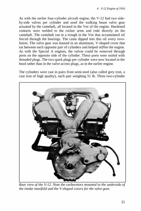
The cylinders were cast in pairs from semi-steel (also called grey iron, a
cast iron of high quality), each pair weighing 51 lb. Three two-cylinder
Rear view of the V-12. Note the carburetors mounted to the underside of the intake manifold and the V-shaped covers for the valve gear.

Duesenberg Aircraft Engines
22
pairs made up each bank of the engine. The left cylinder bank was set
slightly forward of the right cylinder bank to accommodate side-by-side connecting rods. The connecting rods for each pair of opposite cylinders
shared the same crankpin. The brackets supporting the valve rockers
were part of the cylinder casting so that a pair of cylinders and their
rockers could be removed without altering the valve adjustment.
The pistons were constructed of Magnalite aluminum, and again, were
ribbed for strength and heat transfer and used a single three-piece ring. The tubular connecting rods were forged of chrome-nickel steel, first
roughed out, then annealed and machined to within 1/32" of the final
dimensions. They were then heat-treated, machined, and ground to the proper size. Four bolts secured the connecting rods to the crankshaft.
A ghost view of a
Levett Magnalite pis-ton showing the ribs
leading from the
piston crown to the skirt for strength and
heat transfer. This is
not the exact piston that was used in the
V-12, but is of
similar construction.
The large 3" diameter crankshaft had six throws and four main bearings.
It was bored hollow, fitted with special oil tubes for the pressure
lubrication system, and weighed 160 lb. The crankpins were 3" in
diameter and 4 1/2" long.
The crankcase was cast from aluminum alloy and weighed 124 lb. There
were three rectangular access panels along each side of the crankcase. The oil pan attached to the bottom of the crankcase and had a deep sump
for oil accumulation. At the lowest point of the oil pan were two pumps.
The lower scavenge pump kept the crankcase drained at all times. Oil was drawn through a strainer and delivered to an oil cooler and supply
tank. The oil strainer could be removed for cleaning without discon-
necting any pipes. The upper pressure pump brought in cooled oil from
the tank and forced oil to all the bearings and rocker arm pivot shafts.
4. V-12 Engine of 1916
23
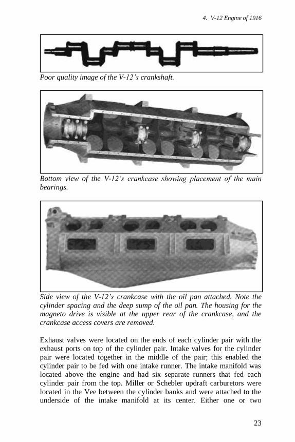
Poor quality image of the V-12’s crankshaft.
Bottom view of the V-12’s crankcase showing placement of the main
bearings.
Side view of the V-12’s crankcase with the oil pan attached. Note the
cylinder spacing and the deep sump of the oil pan. The housing for the magneto drive is visible at the upper rear of the crankcase, and the
crankcase access covers are removed.
Exhaust valves were located on the ends of each cylinder pair with the exhaust ports on top of the cylinder pair. Intake valves for the cylinder
pair were located together in the middle of the pair; this enabled the
cylinder pair to be fed with one intake runner. The intake manifold was located above the engine and had six separate runners that fed each
cylinder pair from the top. Miller or Schebler updraft carburetors were
located in the Vee between the cylinder banks and were attached to the underside of the intake manifold at its center. Either one or two

Duesenberg Aircraft Engines
24
carburetors could be used. At least one other intake manifold was tested.
This manifold was oval-shaped with straight sections directly above the cylinder banks. The two straight sections were joined by U-shaped
manifolds at the front and rear. Carburetors were mounted under the U-
shaped manifolds.
The V-12 engine with the oval intake manifold fitted as displayed at the
Pan-American Aeronautic Exposition in 1917. A carburetor can be seen at the rear of the manifold, and another was most likely at the front. No
further information has been found regarding this intake manifold.
A poor quality image
of the V-12, complete
with electric starter,
on a test stand. Note the intake manifold is
the six runner type,
not the oval mani-fold.

4. V-12 Engine of 1916
25
A double centrifugal water pump was also located at the rear of the
engine; it sent cooling water to each bank of three cylinder pairs through two separate outlets. The water was pumped into the bottom of alumi-
num plates that attached to the outside of the cylinder pair to make the
water jackets. From there, it flowed up to the top of the cylinder, exited
at the top of the cylinder pair through a single outlet, joined a manifold for that bank of cylinders, and then returned to the radiator. Two 12-lead
Bosch magnetos provided dual ignition. The magnetos were mounted
horizontally at the rear of the engine and driven by a worm gear from the camshaft. The electric starter had a gear ratio of 25 to 1. It was mounted
to the timing gear cover at the rear of the engine on the right side.
The engine had a 1917 price tag of $8,500, a very large sum for the time,
but it apparently never evolved past the developmental stage. Some
sources say that only one test engine was built, and others cite a
structural weakness that would require significant redesign to correct. At any rate, the Duesenbergs were too preoccupied with other projects to
continue development of the V-12.
The V-12 ready for a run on a test stand. This appears to be the left side
view of the same set-up seen on the opposite page.
Duesenberg Aircraft Engines
26
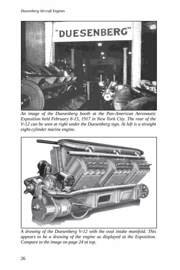
An image of the Duesenberg booth at the Pan-American Aeronautic
Exposition held February 8-15, 1917 in New York City. The rear of the V-12 can be seen at right under the Duesenberg sign. At left is a straight
eight-cylinder marine engine.
A drawing of the Duesenberg V-12 with the oval intake manifold. This
appears to be a drawing of the engine as displayed at the Exposition.
Compare to the image on page 24 at top.
4. V-12 Engine of 1916
27
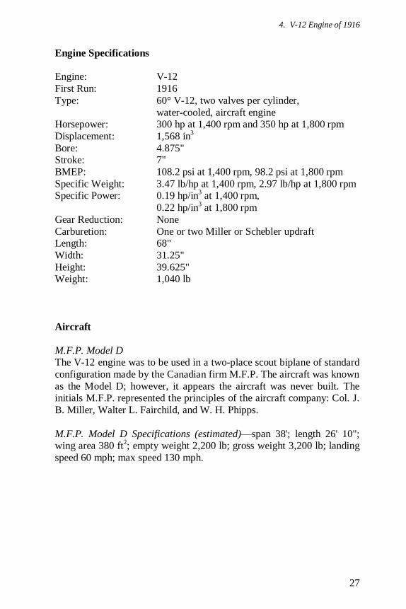
Engine Specifications
Engine: V-12
First Run: 1916
Type: 60° V-12, two valves per cylinder,
water-cooled, aircraft engine Horsepower: 300 hp at 1,400 rpm and 350 hp at 1,800 rpm
Displacement: 1,568 in3
Bore: 4.875" Stroke: 7"
BMEP: 108.2 psi at 1,400 rpm, 98.2 psi at 1,800 rpm
Specific Weight: 3.47 lb/hp at 1,400 rpm, 2.97 lb/hp at 1,800 rpm Specific Power: 0.19 hp/in
3 at 1,400 rpm,
0.22 hp/in3 at 1,800 rpm
Gear Reduction: None
Carburetion: One or two Miller or Schebler updraft Length: 68"
Width: 31.25"
Height: 39.625" Weight: 1,040 lb
Aircraft
M.F.P. Model D The V-12 engine was to be used in a two-place scout biplane of standard
configuration made by the Canadian firm M.F.P. The aircraft was known
as the Model D; however, it appears the aircraft was never built. The initials M.F.P. represented the principles of the aircraft company: Col. J.
B. Miller, Walter L. Fairchild, and W. H. Phipps.
M.F.P. Model D Specifications (estimated)—span 38'; length 26' 10"; wing area 380 ft
2; empty weight 2,200 lb; gross weight 3,200 lb; landing
speed 60 mph; max speed 130 mph.
Duesenberg Aircraft Engines
28
Duesenberg wartime ad from 1918.
29
5. Sixteen-Valve Straight-Four Engine
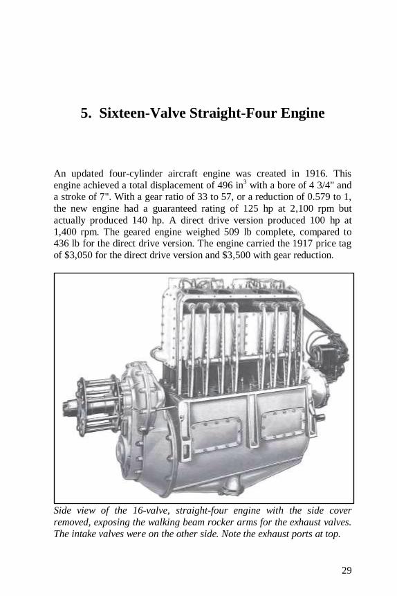
An updated four-cylinder aircraft engine was created in 1916. This
engine achieved a total displacement of 496 in3 with a bore of 4 3/4" and
a stroke of 7". With a gear ratio of 33 to 57, or a reduction of 0.579 to 1,
the new engine had a guaranteed rating of 125 hp at 2,100 rpm but
actually produced 140 hp. A direct drive version produced 100 hp at
1,400 rpm. The geared engine weighed 509 lb complete, compared to 436 lb for the direct drive version. The engine carried the 1917 price tag
of $3,050 for the direct drive version and $3,500 with gear reduction.
Side view of the 16-valve, straight-four engine with the side cover
removed, exposing the walking beam rocker arms for the exhaust valves.
The intake valves were on the other side. Note the exhaust ports at top.
Duesenberg Aircraft Engines
30
This new engine seemed to be based off of the Duesenberg four-cylinder,
16-valve auto racing engine, and again, the walking beam valve gear was used, now to actuate the four tungsten steel valves per cylinder. The left
side of the engine had eight exhaust valves, while the right side had eight
intake valves. The long rocker arms were operated by camshafts on
either side of the aluminum, barrel type crankcase. The whole set-up was enclosed by an oil-tight, aluminum cover. The inlet valves were seated in
a cage threaded into the side of the cylinder combustion chamber. This
cage could be removed to allow inspection of the cylinder and the removal of the exhaust valves. The exhaust valves were seated directly in
the cylinder. All valves had a throat diameter of 1 23/32" although the
intake valves were 1 15/16" in diameter and exhaust valves were 2".
Aluminum plates were attached with screws at the sides and back of the
monobloc cast cylinders. These plates made up the water jacket, similar
to the water jacket of the V-12 engine. Water was circulated via a centrifugal pump at the rear of the engine. Coolant water entered near the
bottom of the aluminum plates and was drawn upward through the
jacket. There were three ports at the top of the engine through which the hot water exited into a manifold and was taken to the radiator.
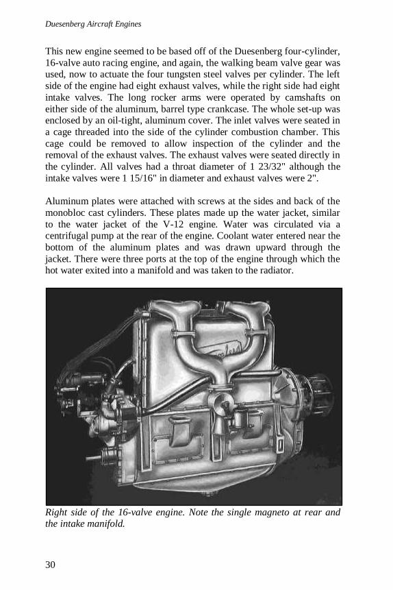
Right side of the 16-valve engine. Note the single magneto at rear and the intake manifold.
5. Sixteen-Valve Straight-Four Engine
31
The exhaust ports were on the left side at the top of the cylinder head.
The intake was on the right side of the head and fed through a manifold that joined the first two and last two cylinders. The two intake runners
traveled down the right side of the engine where they joined together and
were fed by an updraft Miller carburetor. Ignition was provided by a
single, eight-lead magneto that fired two spark plugs at the top of each cylinder and attached to the very end of the engine.
The hollow bore, four-throw crankshaft had three 2 1/2" diameter sup-port bearings; the rear bearing was 4" long, and the front and middle
bearings were 3 1/2" long. The chrome-nickel steel connecting rods had
tubular sections, the same as the V-12 engine, with a four-bolt cap. The connecting rod bearings were 2 1/4" in diameter and 3" long. Again, a
single three-piece piston ring was used on the Magnalite aluminum
pistons, which were ribbed for strength and heat transfer.
The engine employed pressure lubrication of about 25 psi supplied from
a pump submerged in the detachable oil pan. Oil flowed through cored
passageways in the crankshaft to the three main bearings and through tubes located under each connecting rod. These tubes created a spray of
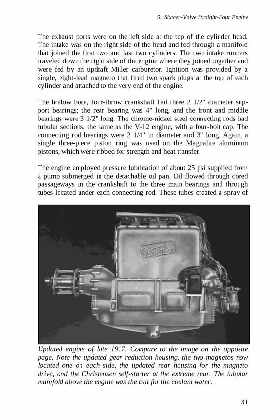
Updated engine of late 1917. Compare to the image on the opposite page. Note the updated gear reduction housing, the two magnetos now
located one on each side, the updated rear housing for the magneto
drive, and the Christensen self-starter at the extreme rear. The tubular
manifold above the engine was the exit for the coolant water.
Duesenberg Aircraft Engines
32
oil that the connecting rod and crankpin would pass through. The oil was
then thrown from the rod and lubricated the rest of the engine. In addition, a splash system accumulated oil in a trough under each
connecting rod. These troughs were constructed so that no matter the
angle of the engine, oil was retained in the trough. The oil returned by
gravity to the pan where it was strained. Oil was also pressure fed to the rocker arm pivot shaft, but the valves used splash lubrication. On both
sides of the crankcase were two rectangular access plates with breathers
incorporated on the right side.
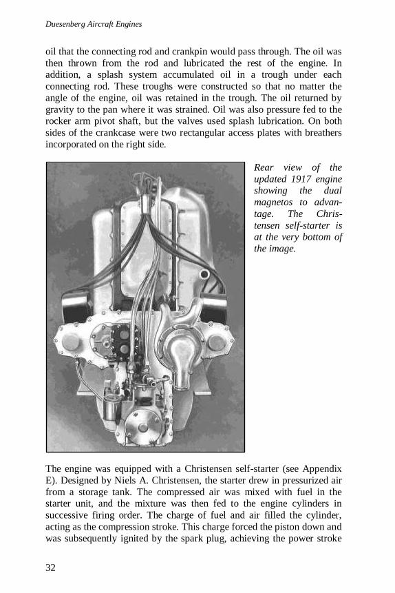
Rear view of the
updated 1917 engine showing the dual
magnetos to advan-
tage. The Chris-
tensen self-starter is at the very bottom of
the image.
The engine was equipped with a Christensen self-starter (see Appendix
E). Designed by Niels A. Christensen, the starter drew in pressurized air
from a storage tank. The compressed air was mixed with fuel in the starter unit, and the mixture was then fed to the engine cylinders in
successive firing order. The charge of fuel and air filled the cylinder,
acting as the compression stroke. This charge forced the piston down and
was subsequently ignited by the spark plug, achieving the power stroke
5. Sixteen-Valve Straight-Four Engine
33
and starting the engine. The starter was attached to the rear of the engine
at the crankshaft. As the engine was turned over by the starter, the crankshaft actuated the starter’s valves that fed the air and fuel mixture to
the next cylinder in firing order.
Late in 1917, the engine was updated and lightened. The changes were mostly external, with the engine maintaining the same bore, stroke, and
power. Two Bosch magnetos, one on each side, were now mounted
toward the rear of the engine. This change necessitated a new casting to encase the horizontal drive for the magnetos. In addition, the crankcase
casting was updated with mounts for the magnetos and a smaller rear
access panel on the crankcase sides to accommodate these updated mounts. The gear reduction housing was also updated. The engine’s
weight decreased 39 lb for the geared version and 9 lb for the direct drive
version, resulting in engine weights of 470 lb and 425 lb, respectively.
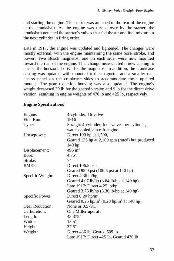
Engine Specifications
Engine: 4-cylinder, 16-valve First Run: 1916
Type: Straight 4-cylinder, four valves per cylinder,
water-cooled, aircraft engine Horsepower: Direct 100 hp at 1,500,
Geared 125 hp at 2,100 rpm (rated) but produced
140 hp
Displacement: 496 in3
Bore: 4.75"
Stroke: 7"
BMEP: Direct 106.5 psi, Geared 95.0 psi (106.5 psi at 140 hp)
Specific Weight: Direct 4.36 lb/hp,
Geared 4.07 lb/hp (3.64 lb/hp at 140 hp)
Late 1917: Direct 4.25 lb/hp, Geared 3.76 lb/hp (3.36 lb/hp at 140 hp)
Specific Power: Direct 0.20 hp/in3
Geared 0.25 hp/in3 (0.28 hp/in
3 at 140 hp)
Gear Reduction: None or 0.579:1
Carburetion: One Miller updraft
Length: 43.375" Width: 15.5"
Height: 37.5"
Weight: Direct 436 lb, Geared 509 lb
Late 1917: Direct 425 lb, Geared 470 lb
Duesenberg Aircraft Engines
34
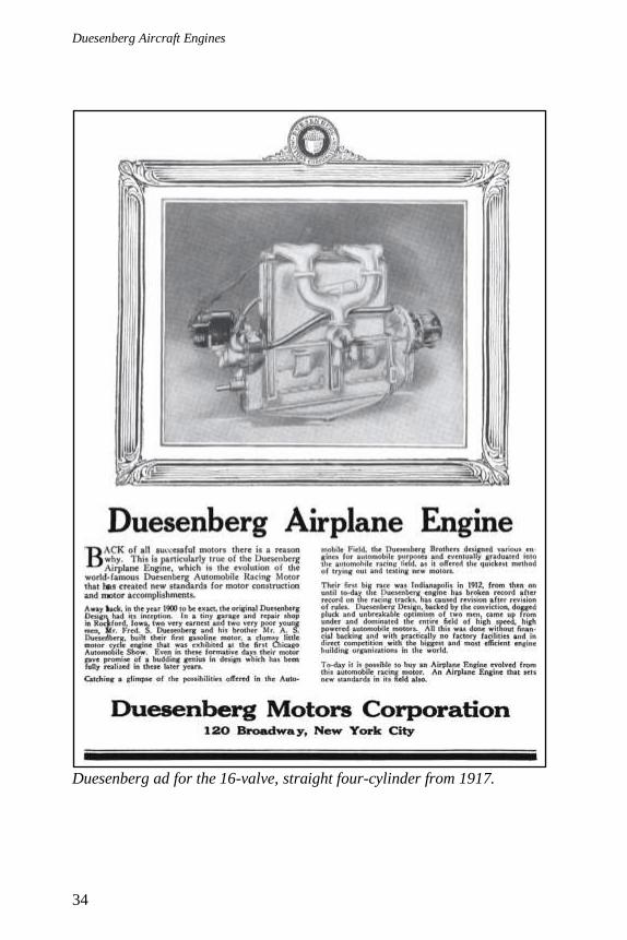
Duesenberg ad for the 16-valve, straight four-cylinder from 1917.
5. Sixteen-Valve Straight-Four Engine
35
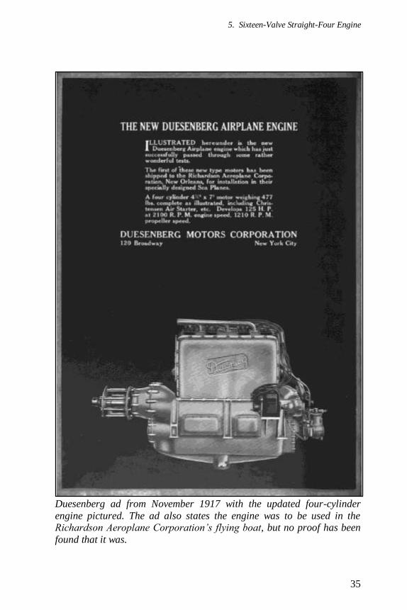
Duesenberg ad from November 1917 with the updated four-cylinder
engine pictured. The ad also states the engine was to be used in the Richardson Aeroplane Corporation’s flying boat, but no proof has been
found that it was.

Duesenberg Aircraft Engines
36
Aircraft
Gallaudet D-1
Reportedly, two special engines of 150 hp were used in the Gallaudet D-
1, which was given the Navy serial number AH-61 (later A59). This was
most likely the first aircraft to be powered by Duesenberg engines. Edson Gallaudet, the aircraft’s designer, traveled to the Duesenberg plant on
February 11, 1916 to supervise the final work on the engines. The first
engine had been tested and shipped to the Gallaudet plant by the end of February, and the second engine followed in mid-March 1916.
The Gallaudet D-1 was a large, two-place biplane pusher fitted with a single large float beneath the fuselage and two smaller wing tip floats.
What was truly unique about the aircraft was the "Gallaudet Drive"
system of propulsion. The two Duesenberg engines were mounted side-
by-side in the fuselage, aft of the cockpit but forward of a four-blade propeller that was mounted in the center of the fuselage between the
wings and tail. The propeller hub was enclosed by a metal ring the same
diameter as the fuselage, with just the propeller blades protruding from the ring. This ring ran on ball bearing races surrounding a fixed steel
drum that was the main structural member supporting the aft fuselage
and tail. Either one or both of the engines could drive the propeller through flexible couplings and with spur reduction gears that meshed
with a large gear attached to the propeller ring.
The D-1 was first flown on July 17, 1916 by David McCullach. Some trouble was experienced with the Duesenberg engines during testing. On
one flight in October 1916, a small break occurred in the head of the
number one piston of the port engine. Duesenberg mechanics installed newly designed pistons and gave the engines a general overhaul.
However, trouble was also encountered with engine overheating and pre-
ignition caused by poor water circulation. The engines were put on a test
stand where more troubleshooting was done and were re-installed in the D-1 by late November 1916. A bit more trouble was encountered with
the engines backfiring. The magnetos were given a thorough cleaning
that resolved the problem. With the engines now working reliably, official Navy trials were conducted in late January 1917, and no engine
trouble was encountered. Late in 1917, the updated, lighter version of the
16-valve engine replaced the original engines installed in the D-1, but by that time the Navy had apparently lost interest in the aircraft. In early
1918, one of the D-1’s engines was removed and shipped to the Bureau
of Steam Engineering in New York City where it was used for
instructional purposes. Only one Gallaudet D-1 aircraft was built.
5. Sixteen-Valve Straight-Four Engine
37
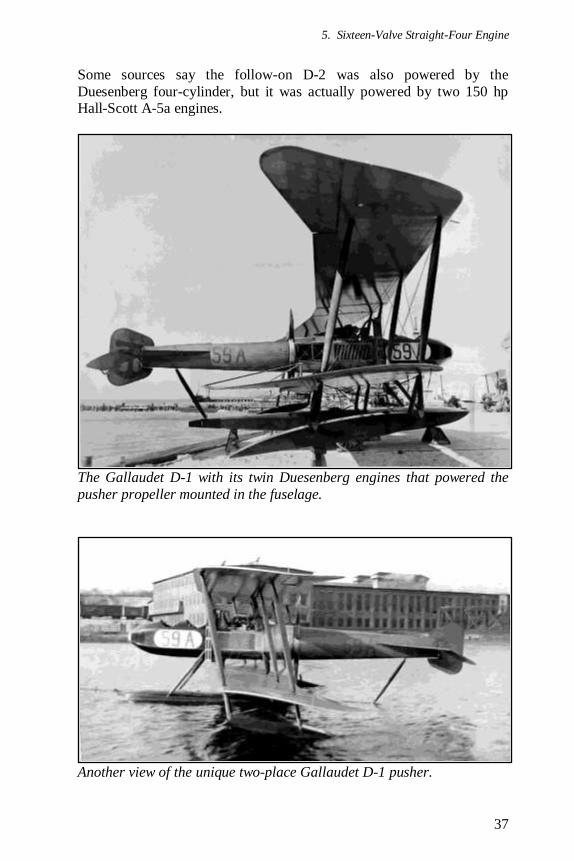
Some sources say the follow-on D-2 was also powered by the
Duesenberg four-cylinder, but it was actually powered by two 150 hp Hall-Scott A-5a engines.
The Gallaudet D-1 with its twin Duesenberg engines that powered the
pusher propeller mounted in the fuselage.
Another view of the unique two-place Gallaudet D-1 pusher.
Duesenberg Aircraft Engines
38
Gallaudet D-1 Specifications—span 48'; length 33'; wing area 656 ft2;
empty weight 3,600 lb; gross weight 4,604 lb; range 288 mi; climb to 5,000' 5 min 32 sec; landing speed 60 mph; max speed 90 mph.
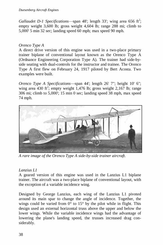
Orenco Type A A direct drive version of this engine was used in a two-place primary
trainer biplane of conventional layout known as the Orenco Type A
(Ordnance Engineering Corporation Type A). The trainer had side-by-side seating with dual-controls for the instructor and trainee. The Orenco
Type A first flew on February 24, 1917 piloted by Bert Acosta. Two
examples were built.
Orenco Type A Specifications—span 44'; length 26' 7"; height 10' 6";
wing area 430 ft2; empty weight 1,476 lb; gross weight 2,167 lb; range
306 mi; climb to 5,000'; 15 min 0 sec; landing speed 38 mph, max speed 74 mph.
A rare image of the Orenco Type A side-by-side trainer aircraft.
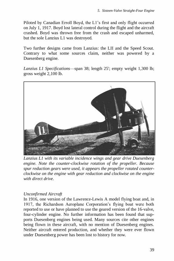
Lanzius L1
A geared version of this engine was used in the Lanzius L1 biplane trainer. The aircraft was a two-place biplane of conventional layout, with
the exception of a variable incidence wing.
Designed by George Lanzius, each wing of the Lanzius L1 pivoted around its main spar to change the angle of incidence. Together, the
wings could be varied from 0° to 15° by the pilot while in flight. This
design used an external horizontal truss above the upper and below the lower wings. While the variable incidence wings had the advantage of
lowering the plane's landing speed, the trusses increased drag con-
siderably.
5. Sixteen-Valve Straight-Four Engine
39
Piloted by Canadian Erroll Boyd, the L1’s first and only flight occurred
on July 1, 1917. Boyd lost lateral control during the flight and the aircraft crashed. Boyd was thrown free from the crash and escaped unharmed,
but the sole Lanzius L1 was destroyed.
Two further designs came from Lanzius: the LII and the Speed Scout. Contrary to what some sources claim, neither was powered by a
Duesenberg engine.
Lanzius L1 Specifications—span 38; length 25'; empty weight 1,300 lb;
gross weight 2,100 lb.
Lanzius L1 with its variable incidence wings and gear drive Duesenberg
engine. Note the counter-clockwise rotation of the propeller. Because
spur reduction gears were used, it appears the propeller rotated counter-clockwise on the engine with gear reduction and clockwise on the engine
with direct drive.
Unconfirmed Aircraft
In 1916, one version of the Lawrence-Lewis A model flying boat and, in
1917, the Richardson Aeroplane Corporation’s flying boat were both reported to use or have planned to use the geared version of the 16-valve,
four-cylinder engine. No further information has been found that sup-
ports Duesenberg engines being used. Many sources cite other engines being flown in these aircraft, with no mention of Duesenberg engines.
Neither aircraft entered production, and whether they were ever flown
under Duesenberg power has been lost to history for now.
Duesenberg Aircraft Engines
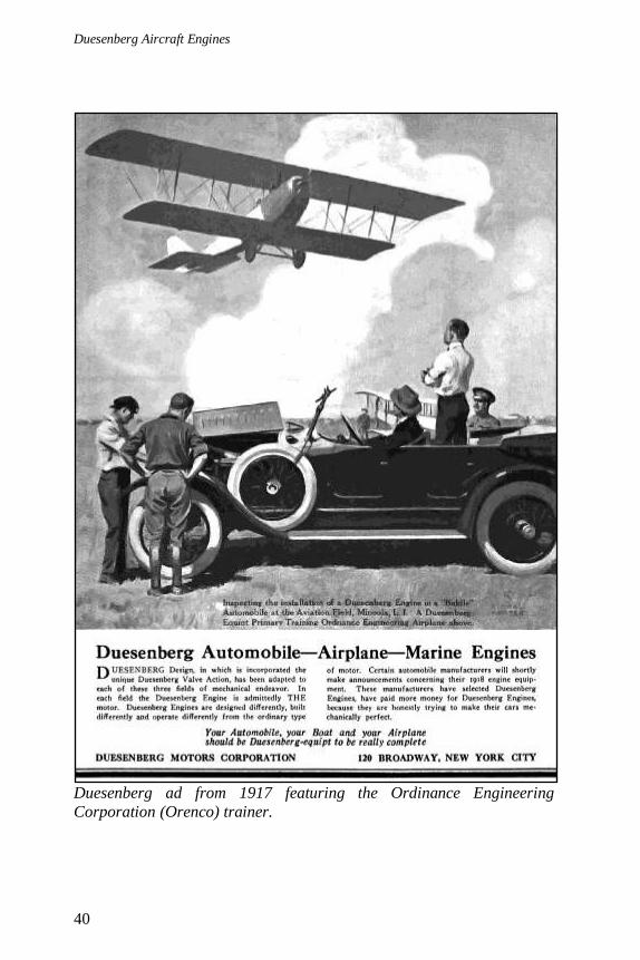
40
Duesenberg ad from 1917 featuring the Ordinance Engineering
Corporation (Orenco) trainer.

5. Sixteen-Valve Straight-Four Engine
41
Lanzius ad from 1917 featuring the L1 and the Duesenberg engine. Note
the external truss above the upper wing and below the lower wing.

Duesenberg Aircraft Engines
42
Duesenberg ad from 1917 featuring what appears to be the Lanzius L1. Note the external trusses on the wings and the exhaust manifold
extending above the engine. Compare to the images of the Lanzius L1 on
pages 39 and 41.
43
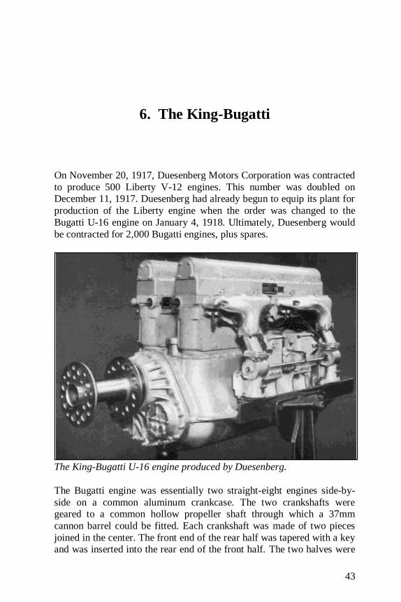
6. The King-Bugatti
On November 20, 1917, Duesenberg Motors Corporation was contracted
to produce 500 Liberty V-12 engines. This number was doubled on December 11, 1917. Duesenberg had already begun to equip its plant for
production of the Liberty engine when the order was changed to the
Bugatti U-16 engine on January 4, 1918. Ultimately, Duesenberg would
be contracted for 2,000 Bugatti engines, plus spares.
The King-Bugatti U-16 engine produced by Duesenberg.
The Bugatti engine was essentially two straight-eight engines side-by-
side on a common aluminum crankcase. The two crankshafts were geared to a common hollow propeller shaft through which a 37mm
cannon barrel could be fitted. Each crankshaft was made of two pieces
joined in the center. The front end of the rear half was tapered with a key and was inserted into the rear end of the front half. The two halves were

Duesenberg Aircraft Engines
44
then drawn together with a nut. Each section of the shaft formed a four-
cylinder crankshaft with the throws all in one plane. The throws of the two sections of the shaft were at right angles.
Connection of the two crankshaft halves.
Each eight-cylinder bank was made up of two cast iron, four-cylinder
blocks. Each cylinder had two vertical inlet valves and a single vertical exhaust valve all actuated by rockers that were operated from the single
overhead camshaft. Each of the four carburetors fed four cylinders via a
water jacketed manifold. Each cylinder exhausted into an individual stack in the space between the cylinder blocks.
Ettore Bugatti had built the prototype U-16 engine in France in 1915. In
1917, he presented this engine to the Bolling Commission, which was sent to Europe from the United States to acquire European military
aeronautical technology that could be built in the United States. During
testing in Paris, an American soldier walked in front of the running engine; he was stuck by the propeller and killed, becoming the first
active duty U.S. casualty of World War I.
With only 37 hours of testing, the Bugatti U-16 prototype was sent to the U.S. for manufacture. It was tested at McCook Field in Dayton, Ohio,
where it promptly broke down. The engine was sent to the Duesenberg
plant, and Charles Brady King of the Signal Corps was sent to rework the engine. After the many changes and improvements specified by King
were incorporated, the engine was now known as the King-Bugatti.
The changes improved the engine in many ways. The splash lubrication
was replaced with a pressure system, and general improvements were
made to the oil circulation. The cylinder water jackets were updated, and
6. The King-Bugatti
45
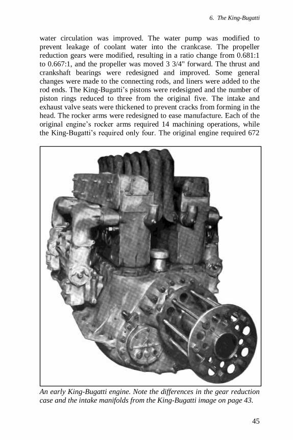
water circulation was improved. The water pump was modified to
prevent leakage of coolant water into the crankcase. The propeller reduction gears were modified, resulting in a ratio change from 0.681:1
to 0.667:1, and the propeller was moved 3 3/4" forward. The thrust and
crankshaft bearings were redesigned and improved. Some general
changes were made to the connecting rods, and liners were added to the rod ends. The King-Bugatti’s pistons were redesigned and the number of
piston rings reduced to three from the original five. The intake and
exhaust valve seats were thickened to prevent cracks from forming in the head. The rocker arms were redesigned to ease manufacture. Each of the
original engine’s rocker arms required 14 machining operations, while
the King-Bugatti’s required only four. The original engine required 672
An early King-Bugatti engine. Note the differences in the gear reduction
case and the intake manifolds from the King-Bugatti image on page 43.

Duesenberg Aircraft Engines
46
machine operations to produce its 48 rocker arms, while the King-
Bugatti required only 192. The front carburetors on each side of the engine were relocated to make fuel distribution more uniform. The
original engine used four magnetos, but the King-Bugatti engine used
only two. This change alone reduced the engine’s weight by 40 pounds.
The end result of all these changes was an engine that was easier to
manufacture, lighter, more powerful, and more reliable. Even so, the first
King-Bugatti engine tested at the Duesenberg plant reportedly blew apart on the test stand in February 1918; miraculously, none of the assembled
dignitaries were injured.
Sectional end view of the King-Bugatti.

6. The King-Bugatti
47
To fix the problems and get the engine into production, nine test engines
ran 110 hours from February to October 1918. The problems were overcome, and the King-Bugatti passed its 50 hour type test at the
Duesenberg engine test house in October 1918.
The King-Bugatti displaced 1,484 in3 from the 16 cylinders of 4.33" bore
and 6.3" stroke. The engine weighed 1,248 lb dry and another 38 lb with
water in the jackets, for a total of 1,286 lb. At 2,000 rpm, it produced 410
hp at the propeller. On a dynamometer in August of 1918, A King-Bugatti test engine achieved a power reading of 500 hp at 2,300 rpm but
with significant wear and tear on the test engine.
Sectional side view of the King-Bugatti.
Top view of the King-Bugatti.
Duesenberg Aircraft Engines
48
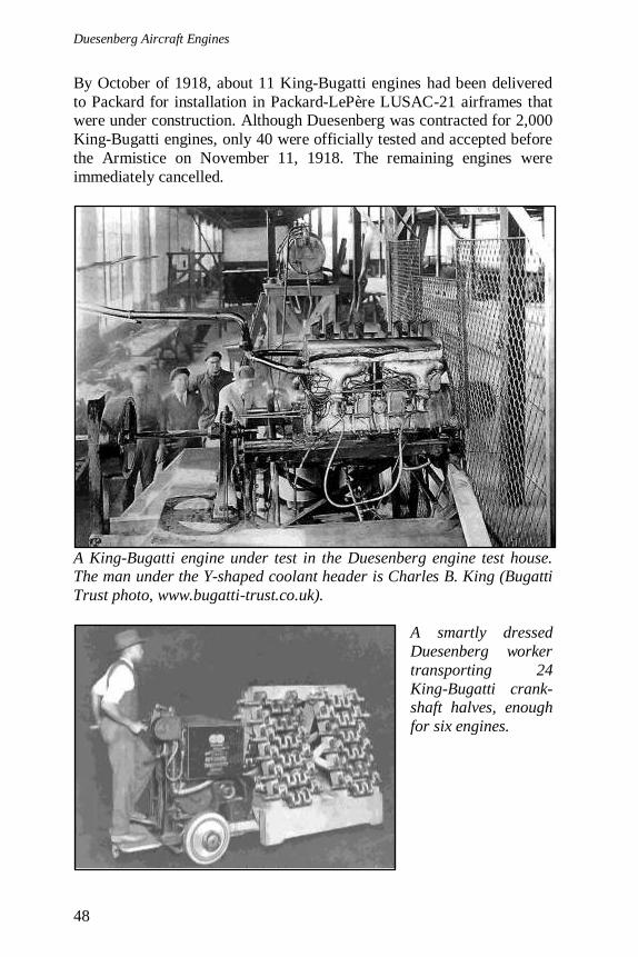
By October of 1918, about 11 King-Bugatti engines had been delivered
to Packard for installation in Packard-LePère LUSAC-21 airframes that were under construction. Although Duesenberg was contracted for 2,000
King-Bugatti engines, only 40 were officially tested and accepted before
the Armistice on November 11, 1918. The remaining engines were
immediately cancelled.
A King-Bugatti engine under test in the Duesenberg engine test house. The man under the Y-shaped coolant header is Charles B. King (Bugatti
Trust photo, www.bugatti-trust.co.uk).
A smartly dressed
Duesenberg worker
transporting 24
King-Bugatti crank-shaft halves, enough
for six engines.
6. The King-Bugatti
49
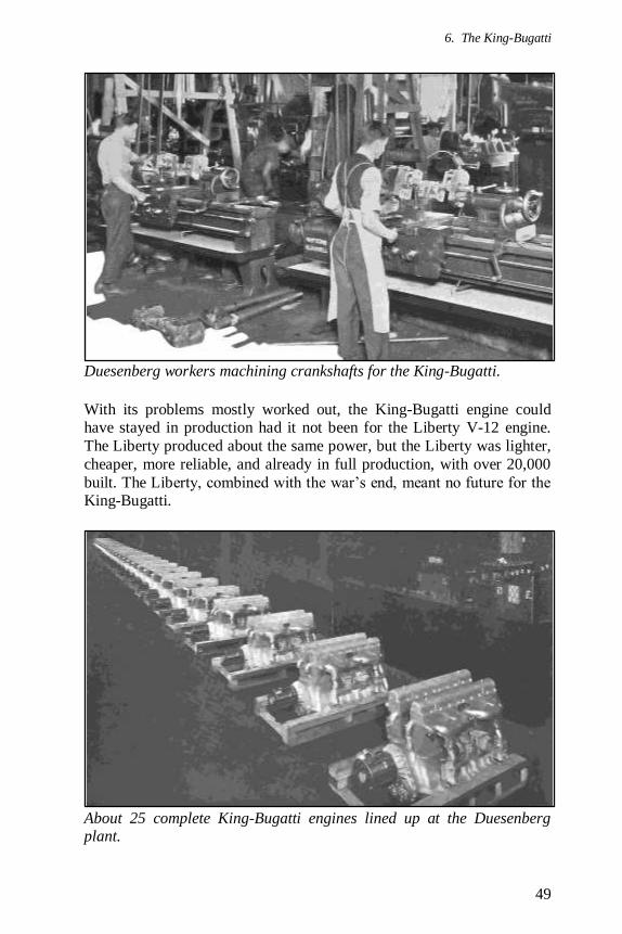
Duesenberg workers machining crankshafts for the King-Bugatti.
With its problems mostly worked out, the King-Bugatti engine could have stayed in production had it not been for the Liberty V-12 engine.
The Liberty produced about the same power, but the Liberty was lighter,
cheaper, more reliable, and already in full production, with over 20,000
built. The Liberty, combined with the war’s end, meant no future for the King-Bugatti.
About 25 complete King-Bugatti engines lined up at the Duesenberg plant.
Duesenberg Aircraft Engines
50
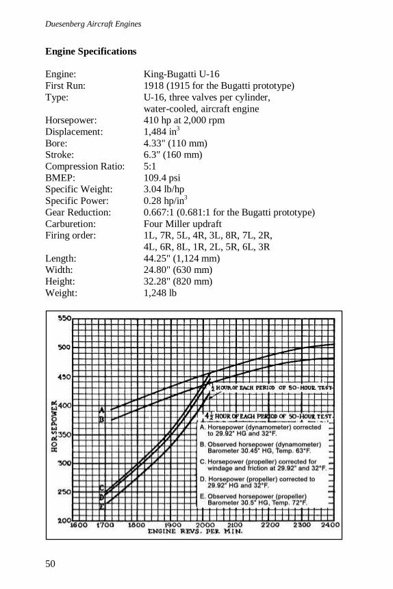
Engine Specifications
Engine: King-Bugatti U-16
First Run: 1918 (1915 for the Bugatti prototype)
Type: U-16, three valves per cylinder,
water-cooled, aircraft engine Horsepower: 410 hp at 2,000 rpm
Displacement: 1,484 in3
Bore: 4.33" (110 mm) Stroke: 6.3" (160 mm)
Compression Ratio: 5:1
BMEP: 109.4 psi Specific Weight: 3.04 lb/hp
Specific Power: 0.28 hp/in3
Gear Reduction: 0.667:1 (0.681:1 for the Bugatti prototype)
Carburetion: Four Miller updraft Firing order: 1L, 7R, 5L, 4R, 3L, 8R, 7L, 2R,
4L, 6R, 8L, 1R, 2L, 5R, 6L, 3R
Length: 44.25" (1,124 mm) Width: 24.80" (630 mm)
Height: 32.28" (820 mm)
Weight: 1,248 lb
6. The King-Bugatti
51
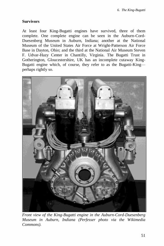
Survivors
At least four King-Bugatti engines have survived, three of them
complete. One complete engine can be seen in the Auburn-Cord-
Duesenberg Museum in Auburn, Indiana; another at the National
Museum of the United States Air Force at Wright-Patterson Air Force Base in Dayton, Ohio; and the third at the National Air Museum Steven
F. Udvar-Hazy Center in Chantilly, Virginia. The Bugatti Trust in
Gotherington, Gloucestershire, UK has an incomplete cutaway King-Bugatti engine which, of course, they refer to as the Bugatti-King—
perhaps rightly so.
Front view of the King-Bugatti engine in the Auburn-Cord-Duesenberg
Museum in Auburn, Indiana (Perfesser photo via the Wikimedia
Commons).

Duesenberg Aircraft Engines
52
Above and Below—The King Bugatti on display at the National Museum
of the United States Air Force at Wright-Patterson Air Force Base in Dayton, Ohio. Note the exhaust stacks between the cylinder banks
(Photos © Gary Brossett 2004, via the Aircraft Engine Historical
Society, www.enginehistory.com).

6. The King-Bugatti
53
Above—King-Bugatti on display at the National Air Museum Steven F.
Udvar-Hazy Center in Chantilly, Virginia (Kogo photo via the Wiki-
media Commons). Below—The partially assembled, cutaway “Bugatti-
King” engine at the Bugatti Trust in Gotherington, Gloucestershire, UK. Completed in 2010, the Bugatti Trust had a replica crankcase built for
this engine (Bugatti Trust photo, www.bugatti-trust.co.uk).
Duesenberg Aircraft Engines
54
Aircraft
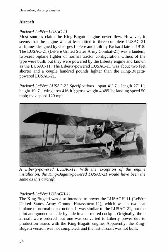
Packard-LePère LUSAC-21
Most sources claim the King-Bugatti engine never flew. However, it
seems that the engine was at least fitted to three complete LUSAC-21
airframes designed by Georges LePère and built by Packard late in 1918. The LUSAC-21 (LePère United States Army Combat-21) was a tandem,
two-seat biplane fighter of normal tractor configuration. Others of the
type were built, but they were powered by the Liberty engine and known as the LUSAC-11. The Liberty-powered LUSAC-11 was about two feet
shorter and a couple hundred pounds lighter than the King-Bugatti-
powered LUSAC-21.
Packard-LePère LUSAC-21 Specifications—span 41' 7"; length 27' 1";
height 10' 7"; wing area 416 ft2; gross weight 4,485 lb; landing speed 50
mph; max speed 120 mph.
A Liberty-powered LUSAC-11. With the exception of the engine
installation, the King-Bugatti-powered LUSAC-21 would have been the
same as this aircraft.
Packard-LePère LUSAGH-11 The King-Bugatti was also intended to power the LUSAGH-11 (LePère
United States Army Ground Harassment-11), which was a two-seat
biplane of normal construction. It was similar to the LUSAC-21, but the
pilot and gunner sat side-by-side in an armored cockpit. Originally, three aircraft were ordered, but one was converted to Liberty power due to
production issues with the King-Bugatti engine. Apparently, the King-
Bugatti version was not completed, and the last aircraft was not built.

6. The King-Bugatti
55
Packard-LePère LUSAGH-11 Specifications (Liberty powered)—span
47' 1"; length 24' 4"; height 10' 10"; wing area 601 ft2; empty weight
3,913 lb; gross weight 5,109 lb; range 278 mi; landing speed 61 mph;
max speed 114 mph.
The Liberty-powered LUSAGH-11. The King-Bugatti-powered version would have been very similar.
Data plate on the King-Bugatti engine in the Auburn-Cord-Duesenberg
Museum.

Duesenberg Aircraft Engines
56
Duesenberg airplane engine ad from 1917 with a stylized Lanzius L1
aircraft. Note the external trusses on the wings.

57
7. Duesenberg Model H
Early in WWI, J. R. Harbeck, President of the Duesenberg Motors
Corporation, suggested a plan to design and build an 800 hp aircraft engine. This engine was larger and more powerful than anything being
produced. The U.S. government awarded a contract to the Duesenberg
Motors Corporation to develop this aircraft engine. The original contract
placed in April 1918 was for two geared engines, but this contract was changed in June to one geared drive engine and one direct drive engine.
This order was possibly expanded to include two engines of each type,
with one pair going to the Army and another pair to the Navy.
Duesenberg Model H engine with gear reduction. Note the plugs for valve removal on each cylinder and the many crankcase breathers that
were only on the right side of the engine. The crankcase was partitioned
into four sections by the air passageways that ran through the crankcase
and fed the carburetors. Each section needed its own breathers.
Fred Duesenberg, with the assistance of William Beckman, Cornelius W.
Van Ranst, and George Dennis, spent much of 1918 on the design of the
Duesenberg Aircraft Engines
58
engine, now known as the Model H. While the Model H was designed at
the same time the Bugatti U-16 was being worked on, the Model H had nothing in common with the Bugatti. However, many of the Model H’s
features did come from the 16-valve, four-cylinder aircraft engine of
1916 and other Duesenberg designs. The first prototype, a geared drive
engine, was completed in June 1918, with the direct drive engine
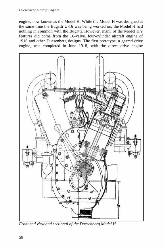
Front end view and sectional of the Duesenberg Model H.

7. Duesenberg Model H
59
following in January of 1919. After the first engine, subsequent engines
incorporated some slight design changes suggested by manufacturing and tests of the first engine.
The Model H was a 45° V-16 aircraft engine. The direct drive version
produced 700 hp at 1,350 rpm, and the geared drive version produced 800 hp at 1,800 rpm. The water-cooled engine had individual cylinders, a
first for Duesenberg, constructed in the fashion pioneered by Mercedes.
The Model H was an undersquare engine with a bore of 6" and a stroke
Rear end view of the Duesenberg Model H.

Duesenberg Aircraft Engines
60
of 7 1/2", giving a total displacement of 3,393 in3. The engine’s com-
pression ratio was about 4.66 to 1. The direct drive version weighed 1,390 lb, and the geared version weighed 1,575 lb.
The gear reduction was the plain spur type, having a 25 to 33 ratio or a
0.758 reduction. The gears were 3 5/8" wide with a 4" face. The pro-peller rotated counter-clockwise because of the spur gears. The reduction
gear housing was cast integral with the aluminum crankcase, but the gear
bearings were located in steel plates secured to the housing by numerous bolts. These very strong steel bearing plates prevented the bearings from
spreading in spite of the enormous radial pressure created by the gears.
The direct drive engine used a different crankcase casting than the geared
drive engine. The crankcase tapered down at the front of the crankshaft
to support the thrust bearing and the propeller hub. There were no
provisions for gear reduction on the direct drive engine casting, and there would have been no way to alter the crankcase to incorporate gear
reduction. Because the propeller for the direct drive engine was mounted
directly on the crankshaft, it was 8" lower than on the geared engine and rotated clockwise. The direct drive engine was only slightly, if at all,
shorter than the geared engine.
Duesenberg Model H cylinder. On the left is the raw cylinder forging. In the middle is the machined barrel; note the ribs. Half of the water jacket
is attached to the barrel. On the right is the complete cylinder. Note the
corrugations in the middle of the completed cylinder’s water jacket.
7. Duesenberg Model H
61
The cylinder barrels were made individually and constructed of chrome-
nickel steel forgings open at both ends. The barrel was case hardened on the inside to afford the best track for the aluminum piston. The cylinder
barrel had seven strengthening ribs running parallel around the outer
circumference. The ribs not only strengthened the barrel, they also
helped dissipate the heat from the cylinder to the cooling water. The barrel was tapered, but average wall thickness was 1/8". A 1/4" base
flange attached the cylinder to the aluminum crankcase via nine studs,
and the cylinder extended 2 3/4" into the crankcase.
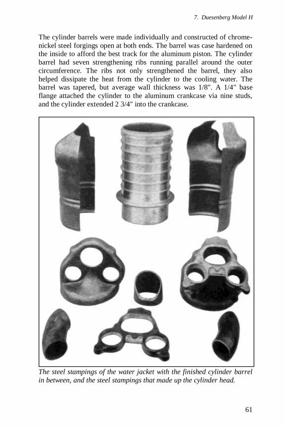
The steel stampings of the water jacket with the finished cylinder barrel
in between, and the steel stampings that made up the cylinder head.
Duesenberg Aircraft Engines
62
The cylinder heads were a series of steel stampings gas-welded together.
The head had an internal thread and screwed over the upper end of the cylinder against the topmost rib. The head was then welded in place to
the top rib of the cylinder barrel. The water jacket was constructed from
three 18-gauge sheet-steel stampings. The stampings were welded
together, to the lowest rib on the cylinder, and to the screwed-on head, completing the jacket. Corrugations were pressed into the jacket at mid-
length to take up differences in expansion and contraction between the
cylinder and jacket as well as to stiffen the jacket wall. The head had two spark plugs on the centerline angled at 45° fore and aft from vertical.
Three valves per cylinder, another first for Duesenberg, were operated by the usual Duesenberg walking beam valve gear located in the Vee of the
engine; however, the rocker arms were much shorter than normal
because the single camshaft was mounted higher in the Vee than it had
been on previous Duesenberg engines. The rocker arms were made of chrome-nickel steel forgings, had hardened steel rollers acting as cam
followers, and were mounted on a hollow, stationary pivot shaft. The
rocker arm pivot shaft was mounted to the top of the camshaft housing, which was a dust and oil-proof enclosure that ran the length of the engine
and contributed to its rigidity when in place. The camshaft housing also
had provisions for a vertical, Delco-designed generator driven from the camshaft bevel gear. The camshaft was an integral forging with a main
diameter of 1 1/4" and was supported by eight babbitt lined aluminum
bearings.
The camshaft was driven by a vertical shaft at the rear of the engine. This
vertical shaft was driven by the crankshaft and at the same speed. The
vertical shaft was supported by annular ball bearings and had bevel gears at both top and bottom. The 2:1 reduction required for the camshaft was
obtained at the upper end of the vertical shaft. Here, a small pinion on the
vertical shaft meshed with a bevel gear on the camshaft with twice the
number of teeth. The bevel pinion at the upper end of the shaft and the bevel gear on the camshaft were secured in place by means of splined
joints. Both the pinion and bevel gear had long hubs where the inner
races for the supporting ball bearings were mounted. The bevel gear at the lower end of the vertical shaft was forged integral with the shaft.
Near its lower end, the vertical shaft carried a helical gear that meshed
with another helical gear on a cross shaft to drive the two Dixie mag-netos. The magnetos were set on mounts cast integral with the crankcase.
For each of the 16 cylinders, there was a single intake valve over a pair
of exhaust valves, all exposed, located toward the Vee of the engine.
7. Duesenberg Model H
63
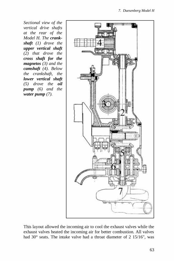
Sectional view of the
vertical drive shafts at the rear of the
Model H. The crank-
shaft (1) drove the
upper vertical shaft (2) that drove the
cross shaft for the
magnetos (3) and the camshaft (4). Below
the crankshaft, the
lower vertical shaft (5) drove the oil
pump (6) and the
water pump (7).
This layout allowed the incoming air to cool the exhaust valves while the
exhaust valves heated the incoming air for better combustion. All valves
had 30° seats. The intake valve had a throat diameter of 2 15/16", was

Duesenberg Aircraft Engines
64
lifted 9/16", and was 6 7/8" long. The two exhaust valves each had a
throat diameter of 2 3/16", were lifted 1/2", and were 6 27/32" long. Each valve had two springs that, when the valve was closed, exerted 60 lb of
combined pressure on each exhaust valve and 70 lb on the intake valve.
Each valve was actuated by a rocker arm, and each rocker arm was
actuated separately by the camshaft. Each valve could be removed by unscrewing the corresponding plug on the opposite side of the cylinder.
Each pair of adjacent cylinders had overlapping lugs on the cylinder heads. A bolt passed through the lugs to tie the two cylinders together.
This connection stiffened the cylinders overall and reduced the side
thrust from the piston on the individual cylinder. In addition, each pair of opposite cylinders were tied together by two steel stampings. These
stampings were clamped to the lugs on the cylinder head exhaust stack
flanges. A stamping was placed above and below the lugs, and bolts
passed through both the stampings and the lugs. Each cylinder had two exhaust stacks extending vertically above the cylinder and positioned
toward the Vee of the engine. Completed, each cylinder weighed 22 lb.
The cast Magnalite aluminum pistons were ribbed inside for strength and
to transfer heat from the piston crown to the piston skirt. The piston was
7" long and had a 1 3/4" wrist pin. Each piston had one 1/2" wide, three piece piston ring. The ring was 7/8" below the top of the piston. The
connecting rods were of the fork-and-blade type, had tubular sections,
and were 12 3/4" long. The upper end of the rod was clamped by a screw
through a split lug on the top of the rod.
The chrome-nickel steel forged crankshaft had eight throws. The four
throws at one end were at right angles to the four at the other end. The crankshaft was supported by four plain bearings and by one ball bearing
at the front (propeller end). All bearings were 2 7/8" in diameter and 3"
long. The plain bearings had Non-Gran bronze shells with babbitt lining.
The total weight of the crankshaft was 199 lb.
From experience with the V-12, Duesenberg had learned that closely
spaced, large holes for the cylinders weakened the crankcase structure, and to compensate for this, the case was made of the barrel type. The
individual cylinders were positioned in pairs. The paired cylinders were
7 1/8" apart at center. The non-paired cylinders were 9" apart at center. The crankcase casting’s bottom was left open and was closed by means
of a shallow aluminum base plate that made up the oil pan. This base
plate, along with the camshaft and rocker arm housing mentioned earlier,
stiffened the crankcase. The propeller end of the crankcase was also left
7. Duesenberg Model H
65
open and was closed by a ribbed steel end-plate, mentioned earlier, that
housed the bearings for the gear reduction.
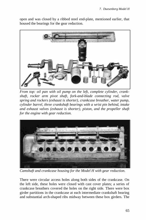
From top: oil pan with oil pump on the left, complete cylinder, crank-
shaft, rocker arm pivot shaft, fork-and-blade connecting rod, valve
spring and rockers (exhaust is shorter), crankcase breather, water pump, cylinder barrel, three crankshaft bearings with a wrist pin behind, intake
and exhaust valves (exhaust is shorter), piston, and the propeller shaft
for the engine with gear reduction.
Camshaft and crankcase housing for the Model H with gear reduction.
There were circular access holes along both sides of the crankcase. On
the left side, these holes were closed with cast cover plates; a series of
crankcase breathers covered the holes on the right side. There were box
girder partitions in the crankcase at each intermediate crankshaft bearing and substantial arch-shaped ribs midway between these box girders. The
Duesenberg Aircraft Engines
66
inside panels of the case’s lower portion had diagonal or cross ribs to add
to the strength of the case. A flange to support the engine in the aircraft fuselage was cast on each side of the case at the height of the crankshaft
axis. The weight of the crankcase casing when machined was 180 lb.
The oil pump was mounted at the rear of the engine, below the crankshaft, and inside the crankcase oil pan. The water pump was
mounted on the outside of the oil pan, directly below the oil pump. Both
the oil pump and the water pump were driven at crankshaft speed through the same vertical drive shaft that extended below the crankshaft.
This drive shaft was connected to the oil pump and was integrally forged
with the driving bevel gear. The drive shaft for the oil and water pumps was in line with the drive shaft for the camshaft and magnetos, but the
two shafts were not connected.
The dry sump lubrication system consisted of a two-section oil pump. One section was a triple-gear feed pump and the other a scavenging
pump. The delivery pump forced oil to each main bearing through a
single main oil line fitted into the crankcase. The main distributing line was fitted into the crankcase with packing glands; this was necessary
because of the comparatively high oil pressure employed for the time,
which rose to 75 psi when the engine ran at full speed.
A tube containing a regulator that reduced the oil pressure was taken off
at the valve drive end of the main oil distributing line. This low pressure
line extended along the top of the crank chamber, and from it there were two upward passages: one to the hollow camshaft and one to the hollow
rocker pivot shaft. The excess oil from the rocker pivot shaft dropped
onto the camshaft and ensured effective lubrication of the cams and rollers. The oil from the ends of the hollow camshaft returned through
the reduction gear case at the front of the engine and through the housing
of the vertical shaft at the rear of the engine. There was a dam at the
vertical drive shaft end that determined the oil level in the camshaft housing. There were also passages through the cylinder flanges and
cylinder walls; oil was injected through these passages and into the lower
part of the cylinders to ensure their lubrication.
A tube from the low pressure distributing pipe extended through the
upper part of the crankcase and into the gear reduction case. This tube had three lateral outlets opposite the reduction gear so that there was a
constant supply of oil to the gear teeth as they came in contact. There
was also a constant supply of oil in the bottom of the gear reduction case.
The height of this oil was determined by the ball bearing on the end of

7. Duesenberg Model H
67
the crankshaft. The scavenging
pump drew oil through large-size strainers at each end of the
crankcase. The two inlet pipes
allowed the scavenging pump to
drain the crankcase no matter which direction the engine was
inclined.
The crankpin bearings got their
oil supply through passages
drilled through the crankshaft from the main bearings, which
received direct pressure lubri-
cation. Oil for the crankpin
bearing closest to the propeller end had to pass from the nearest
intermediate bearing through a
short crank arm, a crankpin, and a long crank arm.
Water was used as the coolant, and it was circulated through the
cooling system from the cen-
trifugal pump, located at the
bottom rear of the engine. The pump turned at crankshaft speed
and fed cooling water to the
engine via two 1 7/8" diameter outlet tubes, one feeding each
bank of cylinders. The water
entered the jackets of the
cylinder heads through welded water distributors that separated
the flow into three streams. Each
exhaust valve had its own stream leading directly beneath
the exhaust port. The third
stream led to the outside of the cylinder jacket. Water was taken
out of the cylinder through an
opening at the top of the
cylinder. In addition to the

Duesenberg Aircraft Engines
68
regular water return connection, there was an outlet connection at the
bottom of each cylinder jacket to prevent dead spaces from forming in the cooling jacket. The intake manifolds were water-jacketed, and the
water leaving the cylinder jackets passed through the jackets of the
intake manifolds and then to the radiator. The water inlet temperature
was 125° F, and the outlet temperature was 155° F.
The engines were equipped with both magnetos and battery ignition.
Two eight-lead Dixie magnetos were fitted to the rear of the engine and driven from the upper vertical drive shaft. The mountings permitted any
standard magnetos to be used. The battery ignition used a Delco dis-
tributor directly in line with the camshaft and bolted to the vertical shaft housing. The distributor was driven by an integral key engaging a
transverse slot cut into the camshaft. The distributor was double-sided,
with eight cables extending from each side. Each cable fired one of the
spark plugs in each cylinder. The magnetos fired the other spark plug. A Philbrin battery ignition system with a generator turning at twice crank-
shaft speed was also tested successfully. The firing order was as follows:
4L, 1R, 8L, 5R, 2L, 3R, 6L, 7R, 1L, 4R, 5L, 8R, 3L, 2R, 7L, 6R.
Rear view of the
Model H on a test stand. The manifold
extending to the top
of the image is the
water coolant line to take hot water away
from the engine. The
double-sided distrib-utor can be seen in
the middle of the
image. Below the dis-
tributor and mounted on the sides of the
vertical shaft housing
are the two mag-netos. At the bottom
rear of the engine is
the Christensen self-starter that fed the
left bank of cylinders.
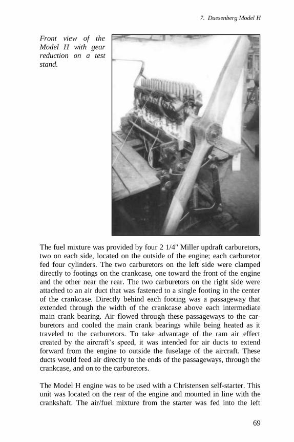
7. Duesenberg Model H
69
Front view of the
Model H with gear reduction on a test
stand.
The fuel mixture was provided by four 2 1/4" Miller updraft carburetors,
two on each side, located on the outside of the engine; each carburetor
fed four cylinders. The two carburetors on the left side were clamped
directly to footings on the crankcase, one toward the front of the engine and the other near the rear. The two carburetors on the right side were
attached to an air duct that was fastened to a single footing in the center
of the crankcase. Directly behind each footing was a passageway that extended through the width of the crankcase above each intermediate
main crank bearing. Air flowed through these passageways to the car-
buretors and cooled the main crank bearings while being heated as it
traveled to the carburetors. To take advantage of the ram air effect created by the aircraft’s speed, it was intended for air ducts to extend
forward from the engine to outside the fuselage of the aircraft. These
ducts would feed air directly to the ends of the passageways, through the crankcase, and on to the carburetors.
The Model H engine was to be used with a Christensen self-starter. This unit was located on the rear of the engine and mounted in line with the
crankshaft. The air/fuel mixture from the starter was fed into the left
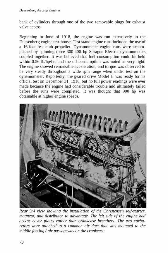
Duesenberg Aircraft Engines
70
bank of cylinders through one of the two removable plugs for exhaust
valve access.
Beginning in June of 1918, the engine was run extensively in the
Duesenberg engine test house. Test stand engine runs included the use of
a 16-foot test club propeller. Dynamometer engine runs were accom-plished by spinning three 300-400 hp Sprague Electric dynamometers
coupled together. It was believed that fuel consumption could be held
within 0.56 lb/hp/hr, and the oil consumption was noted as very light. The engine showed remarkable acceleration, and torque was observed to
be very steady throughout a wide rpm range when under test on the
dynamometer. Reportedly, the geared drive Model H was ready for its official test on December 31, 1918, but no full power readings were ever
made because the engine had considerable trouble and ultimately failed
before the runs were completed. It was thought that 900 hp was
obtainable at higher engine speeds.
Rear 3/4 view showing the installation of the Christensen self-starter, magneto, and distributor to advantage. The left side of the engine had
access cover plates rather than crankcase breathers. The two carbu-
retors were attached to a common air duct that was mounted to the
middle footing / air passageway on the crankcase.
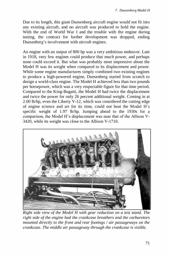
7. Duesenberg Model H
71
Due to its length, this giant Duesenberg aircraft engine would not fit into
any existing aircraft, and no aircraft was produced to hold the engine. With the end of World War I and the trouble with the engine during
testing, the contract for further development was dropped, ending
Duesenberg’s involvement with aircraft engines.
An engine with an output of 800 hp was a very ambitious endeavor. Late
in 1918, very few engines could produce that much power, and perhaps
none could exceed it. But what was probably most impressive about the Model H was its weight when compared to its displacement and power.
While some engine manufactures simply combined two existing engines
to produce a high-powered engine, Duesenberg started from scratch to design a world-class engine. The Model H achieved less than two pounds
per horsepower, which was a very respectable figure for that time period.
Compared to the King-Bugatti, the Model H had twice the displacement
and twice the power for only 26 percent additional weight. Coming in at 2.00 lb/hp, even the Liberty V-12, which was considered the cutting edge
of engine science and art for its time, could not beat the Model H’s
specific weight of 1.97 lb/hp. Jumping ahead to the 1930s for a comparison, the Model H’s displacement was near that of the Allison V-
3420, while its weight was close to the Allison V-1710.
Right side view of the Model H with gear reduction on a test stand. The
right side of the engine had the crankcase breathers and the carburetors mounted directly to the front and rear footings / air passageways on the
crankcase. The middle air passageway through the crankcase is visible.
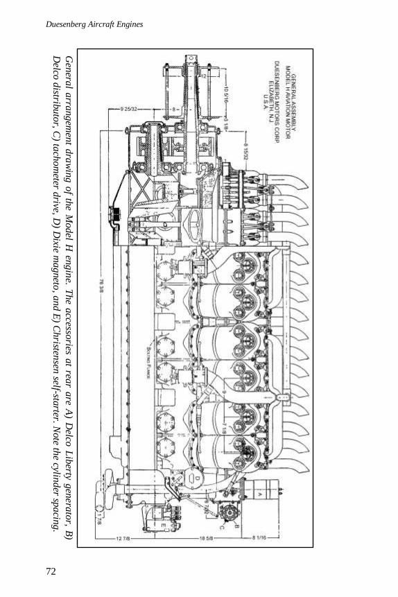
Duesenberg Aircraft Engines
72
The
Gen
eral a
rran
gem
ent d
raw
ing o
f the M
odel H
engin
e. The a
ccessories a
t rear a
re A) D
elco L
iberty g
enera
tor, B
)
Delco
distrib
uto
r, C) ta
chom
eter drive, D
) Dixie m
agneto
, and E
) Christen
sen self-sta
rter. Note th
e cylind
er spacin
g.

7. Duesenberg Model H
73
Model H hooked up to the three Sprague dynamometers in the
Duesenberg engine test house.
Engine Specifications
Engine: Model H
First Run: 1918
Type: 45° V-16, three valves per cylinder, water-cooled, aircraft engine
Horsepower: Direct 700 hp at 1,350 rpm
Geared 800 hp at 1,800 rpm Displacement: 3,393 in
3
Bore: 6"
Stroke: 7.5"
Compression Ratio: 4.66:1 BMEP: Direct 121.0 psi, Geared 103.7 psi
Specific Weight: Direct 1.99 lb/hp, Geared 1.97 lb/hp
Specific Power: Direct 0.21 hp/in3, Geared 0.24 hp/in
3
Gear Reduction: None or 0.758:1
Carburetion: Four 2.25" Miller updraft
Firing order: 4L, 1R, 8L, 5R, 2L, 3R, 6L, 7R, 1L, 4R, 5L, 8R, 3L, 2R, 7L, 6R
Length: 88.75"
Width: 32"
Height: 38.875" Weight: Direct 1,390 lb, Geared 1,575 lb

Duesenberg Aircraft Engines
74
Duesenberg Model H on a test stand in the Duesenberg engine test
house. The worker gives some perspective to the size of the engine.
Survivors
Amazingly, two Model H engines survive. While not complete, one
engine is on display at the Auburn-Cord-Duesenberg Automobile
Museum in Auburn, Indiana, which was once the Duesenberg national headquarters. This engine is a geared drive version and was donated by
Dee and Georgia Howard of San Antonio, Texas.
The other surviving engine is a direct drive version and is in storage at
the National Air and Space Museum’s Garber Facility in Silver Hill,
Maryland. The engine appears to be nearly complete; it even includes the Christensen self-starter, magnetos, generator, distributor, intake mani-
folds, and carburetors. However, it is missing the air duct for the two
carburetors on the right side of the engine.

7. Duesenberg Model H
75
Above—Right side of the Model H as displayed at the Auburn-Cord-
Duesenberg Automobile Museum in Auburn, Indiana. Of note are the
crankcase breathers and the air passageways through the crankcase.
Below—Bottom view from the left rear of the Model H showing the engine mounting flange that was cast the entire length of the crankcase.
Also visible is the oil pan and how it is attached to the crankcase. Note
the footings to mount the carburetors to the air passageways through the crankcase (Martt Clupper photos via AirPigz, www.airpigz.com).
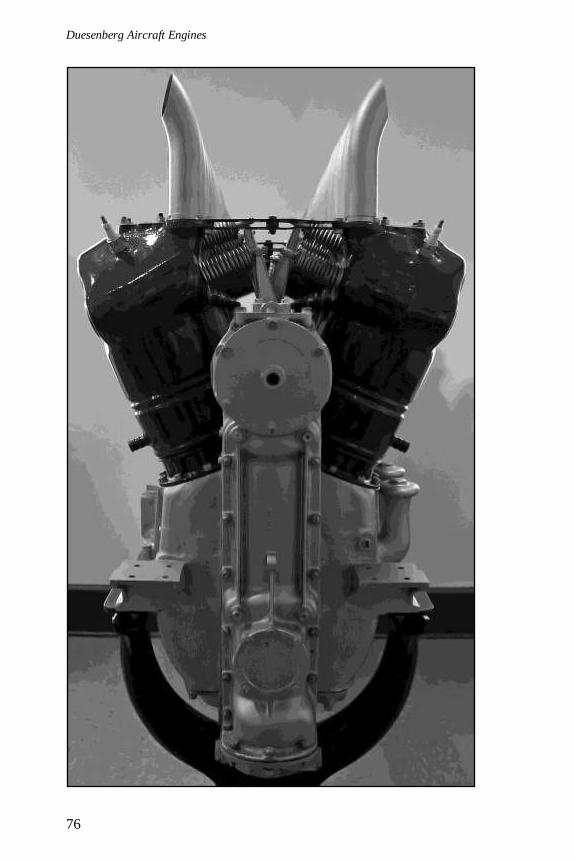
Duesenberg Aircraft Engines
76
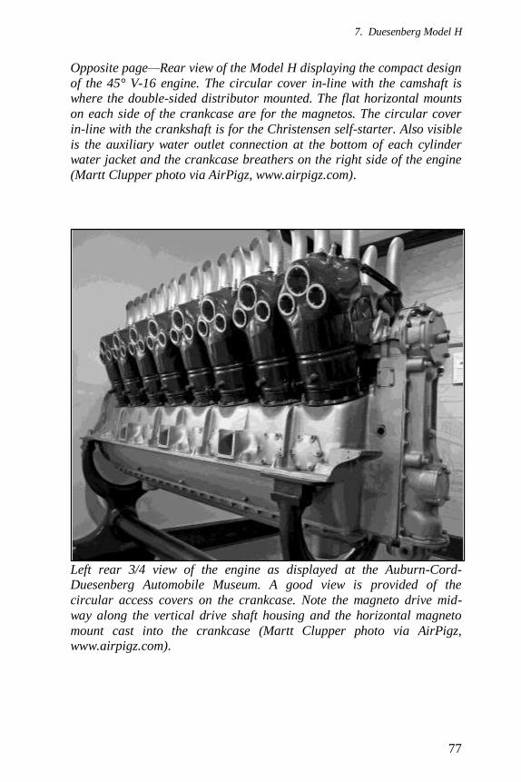
7. Duesenberg Model H
77
Opposite page—Rear view of the Model H displaying the compact design
of the 45° V-16 engine. The circular cover in-line with the camshaft is where the double-sided distributor mounted. The flat horizontal mounts
on each side of the crankcase are for the magnetos. The circular cover
in-line with the crankshaft is for the Christensen self-starter. Also visible
is the auxiliary water outlet connection at the bottom of each cylinder water jacket and the crankcase breathers on the right side of the engine
(Martt Clupper photo via AirPigz, www.airpigz.com).
Left rear 3/4 view of the engine as displayed at the Auburn-Cord-Duesenberg Automobile Museum. A good view is provided of the
circular access covers on the crankcase. Note the magneto drive mid-
way along the vertical drive shaft housing and the horizontal magneto
mount cast into the crankcase (Martt Clupper photo via AirPigz, www.airpigz.com).

Duesenberg Aircraft Engines
78
View of the walking beam rocker arms for the 48 valves. Note the steel
stampings tying opposite cylinders together. The second one from bottom
is missing (Martt Clupper photo via AirPigz, www.airpigz.com).
A view looking down the Vee of the Model H. The plate in the foreground
is where the generator would mount (Martt Clupper photo via AirPigz, www.airpigz.com).
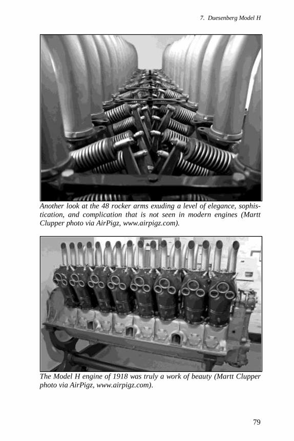
7. Duesenberg Model H
79
Another look at the 48 rocker arms exuding a level of elegance, sophis-
tication, and complication that is not seen in modern engines (Martt Clupper photo via AirPigz, www.airpigz.com).
The Model H engine of 1918 was truly a work of beauty (Martt Clupper
photo via AirPigz, www.airpigz.com).
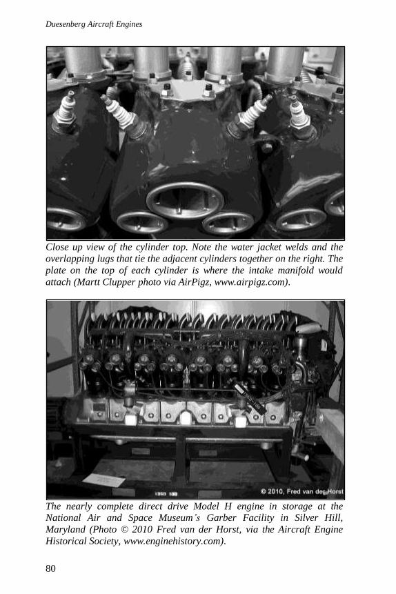
Duesenberg Aircraft Engines
80
Close up view of the cylinder top. Note the water jacket welds and the
overlapping lugs that tie the adjacent cylinders together on the right. The
plate on the top of each cylinder is where the intake manifold would
attach (Martt Clupper photo via AirPigz, www.airpigz.com).
The nearly complete direct drive Model H engine in storage at the National Air and Space Museum’s Garber Facility in Silver Hill,
Maryland (Photo © 2010 Fred van der Horst, via the Aircraft Engine
Historical Society, www.enginehistory.com).
81
Epilogue
Duesenberg Motors Corporation had spent much of its capital on its
facilities in New Jersey and on the development of aircraft engines. Once WWI ended and the government contracts were cancelled, the company
found itself in financial distress. Duesenberg ceased development of
aircraft engines, and the company was reorganized.
Duesenberg Motors Corporation filed a breach of contract lawsuit
against the U.S. Government, alleging that the government did not
provide the necessary information for a production-ready Bugatti engine. Duesenberg lost the case on the grounds that the government was
unaware the Bugatti engine was not ready for production and was rightly
more concerned with ending the war than producing the engine.
While none of the Duesenberg aircraft engines achieved any level of
commercial success, they do occupy a level of historical importance for
their unique features. The enclosed and well lubricated valve gear used on most of their engines stands out as a viable solution to the valve issues
that plagued early aircraft engines. And while many engines got by with
splash lubrication, Duesenberg’s use of pressure lubrication is another example of their understanding of what was needed to ensure reliable,
high-powered engines. The quality of the engines and the thoroughness
of the designs turned out by the small Duesenberg design department give a glimpse of the inherent genius of Fred Duesenberg.
As an anecdotal note on born intuition versus learned calculation, before
his death in 1932, Fred Duesenberg was shown the prototype Allison V-1710 at the Allison Engineering Company plant in Indianapolis, Indiana.
Duesenberg liked the design but commented that he felt the crankshaft
seemed a little weak to his eye. The Allison engineers assured him that the design had been carefully calculated and that it had ample strength.
But during tests of the V-1710, it was found that the crankshaft needed to
be redesigned and strengthened to cure vibration issues.
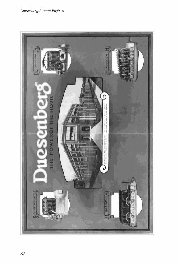
Duesenberg Aircraft Engines
82
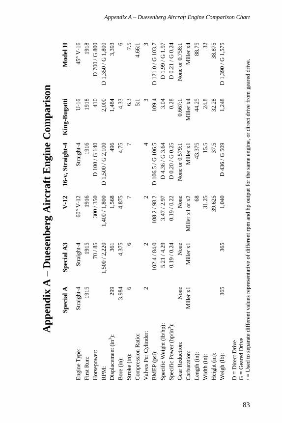
Appendix A – Duesenberg Aircraft Engine Comparison Chart
83
Ap
pen
dix
A –
Du
ese
nb
erg
Air
craft
En
gin
e C
om
pa
ris
on
Sp
ecia
l A
S
pecia
l A
3
V-1
2
16-v
, S
traig
ht-
4
Kin
g-B
ug
att
i M
od
el
H
Engin
e T
ype:
Str
aight-
4
Str
aight-
4
60°
V-1
2
Str
aight-
4
U-1
6
45°
V-1
6
Fir
st R
un:
1915
1915
1916
1916
1918
1918
Hors
epow
er:
70 /
85
300 / 3
50
D 1
00 /
G 1
40
410
D 7
00 /
G 8
00
RP
M:
1,5
00 /
2,2
20
1,4
00 /
1,8
00
D 1
,500 /
G 2
,100
2,0
00
D 1
,350 /
G 1
,800
Dis
pla
cem
ent
(in
3):
299
361
1,5
68
496
1,4
84
3,3
93
Bore
(in
):
3.9
84
4.3
75
4.8
75
4.7
5
4.3
3
6
Str
oke
(in):
6
6
7
7
6.3
7
.5
Com
pre
ssio
n R
atio
:
5:1
4.6
6:1
Val
ves
Per
Cyl
ind
er:
2
2
2
4
3
3
BM
EP
(psi
):
10
2.4
/ 8
4.0
108.2
/ 9
8.2
D
106.5
/ G
106.5
109.4
D
121.0
/ G
103.7
Spec
ific
Wei
ght (l
b/h
p):
5.2
1 /
4.2
9
3.4
7 /
2.9
7
D 4
.36 /
G 3
.64
3.0
4
D 1
.99 /
G 1
.97
Spec
ific
Pow
er (
hp/i
n3):
0.1
9 /
0.2
4
0.1
9 /
0.2
2
D 0
.20 /
G 0
.25
0.2
8
D 0
.21 /
G 0
.24
Gea
r R
educt
ion:
None
None
None
None
or
0.5
79:1
0.6
67:1
N
one
or
0.7
58:1
Car
bura
tion:
Mil
ler
x1
Mil
ler
x1
Mil
ler
x1 o
r x2
Mil
ler
x1
Mil
ler
x4
Mil
ler
x4
Len
gth
(in
):
68
43.3
75
44.2
5
88.7
5
Wid
th (
in):
31.2
5
15.5
24.8
32
Hei
ght
(in):
39.6
25
37.5
32.2
8
38.8
75
Wei
gh (
lb):
365
365
1,0
40
D 4
36 /
G 5
09
1,2
48
D 1
,390 /
G 1
,575
D =
Dir
ect
Dri
ve
G =
Gea
red D
rive
/ =
Use
d t
o s
epar
ate
dif
fere
nt
val
ues
rep
rese
nta
tive
of
dif
fere
nt
rpm
and h
p o
utp
ut
for
the
sam
e en
gin
e, o
r dir
ect
dri
ve
from
gea
red d
rive.

Duesenberg Aircraft Engines
84
Duesenberg wartime ad from 1918.
85
Appendix B – Duesenberg Valve Gear Patent
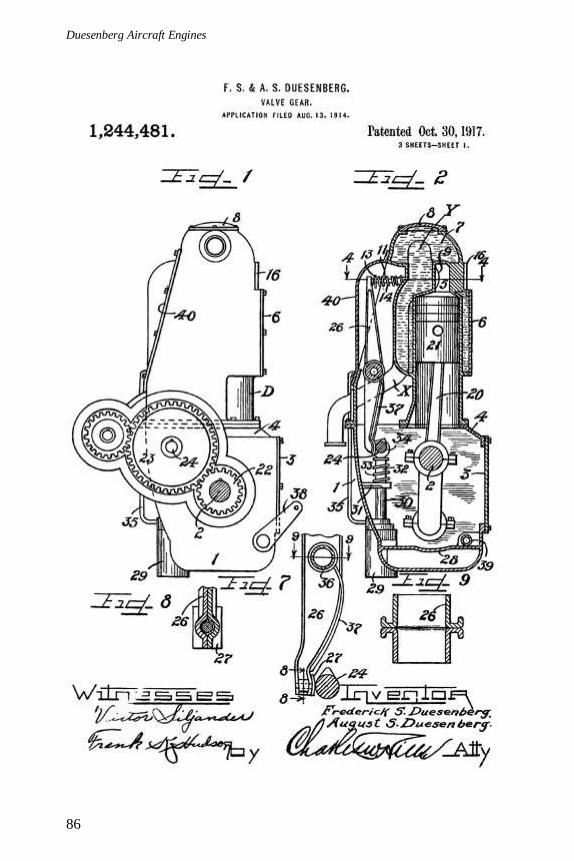
Duesenberg Aircraft Engines
86

Appendix B – Duesenberg Valve Gear Patent
87
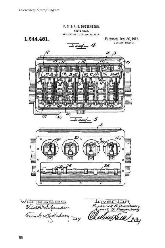
Duesenberg Aircraft Engines
88
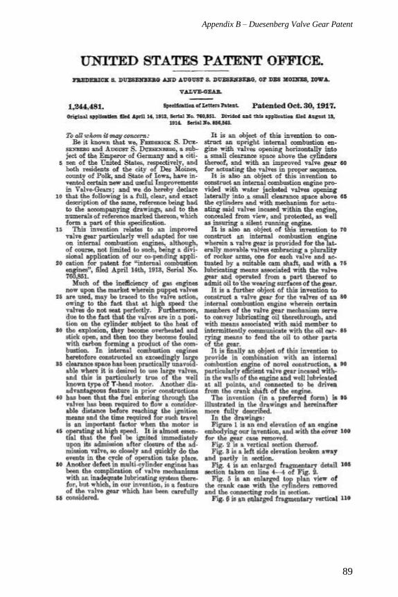
Appendix B – Duesenberg Valve Gear Patent
89
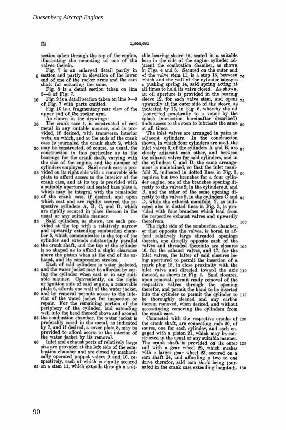
Duesenberg Aircraft Engines
90
Appendix B – Duesenberg Valve Gear Patent
91
Duesenberg Aircraft Engines
92
Appendix B – Duesenberg Valve Gear Patent
93

Duesenberg Aircraft Engines
94
Levett Pistons ad from late January 1919 with a letter from Fred
Duesenberg thanking the company for their pistons. Most likely, Levett
Magnalite aluminum pistons were used in all Duesenberg aircraft engines.

95
Appendix C – The King V-12 Aero Engine
According to The Bulletin of the Airplane Engineering Department, the
Duesenberg Motors Corporation was contracted to build five prototypes of the King V-12 aero engine. This contract lasted only briefly, from late
June 1918 to mid-October 1918.
Front sectional view and rear end view of the King V-12 engine.
Designed by Charles B. King, the King aero engine was a 45° V-12
engine. With a bore of 5 1/2" and a stroke of 7", the engine displaced
1,995 in3. A gear reduction of 0.692:1 was fitted, and the engine was
rated at 500 hp at 1,700 rpm (1,175 rpm at the propeller); 550 hp at 1,880 rpm (1,300 rpm at the propeller); and 600 hp at 2,075 rpm (1,435 rpm at
the propeller). The compression ratio was 5:1, and the engine weighed
990 lb dry. The engine was intended as a Liberty V-12 replacement and

Duesenberg Aircraft Engines
96
could be installed in place of the Liberty engine. King’s V-12 was a
compact design and had less frontal area than the Liberty.
The engine was of all aluminum, monobloc construction and featured
three valves per cylinder. The one intake and two exhaust valves for each
cylinder were actuated by a single overhead camshaft. The head for each bank of six cylinders was cast complete, and the valve gear was enclosed
Sectional side view of the King V-12.
Various pieces of the King V-12, including a cylinder head, engine case (bottom view), valves, rockers, and a camshaft. Note the sectioned head
on the left and the carburetor on the far right.
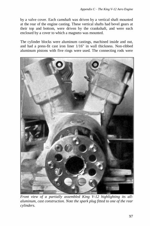
Appendix C – The King V-12 Aero Engine
97
by a valve cover. Each camshaft was driven by a vertical shaft mounted
at the rear of the engine casting. These vertical shafts had bevel gears at their top and bottom, were driven by the crankshaft, and were each
enclosed by a cover to which a magneto was mounted.
The cylinder blocks were aluminum castings, machined inside and out, and had a press-fit cast iron liner 1/16" in wall thickness. Non-ribbed
aluminum pistons with five rings were used. The connecting rods were
Front view of a partially assembled King V-12 highlighting its all-
aluminum, cast construction. Note the spark plug fitted to one of the rear cylinders.
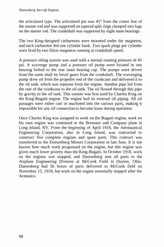
Duesenberg Aircraft Engines
98
the articulated type. The articulated pin was 45° from the center line of
the master rod and was supported on tapered split rings clamped into lugs on the master rod. The crankshaft was supported by eight main bearings.
The two King-designed carburetors were mounted under the magnetos,
and each carburetor fed one cylinder bank. Two spark plugs per cylinder were fired by two Dixie magnetos running at crankshaft speed.
A pressure oiling system was used with a normal running pressure of 45 psi. A scavenge pump and a pressure oil pump were located in one
housing bolted to the rear main bearing cap. The pumps were driven
from the same shaft by bevel gears from the crankshaft. The scavenging pump drew oil from the propeller end of the crankcase and delivered it to
the oil tank, which was separate from the engine. Another pipe led from
the rear of the crankcase to the oil tank. The oil flowed through this pipe
by gravity to the oil tank. This system was first used by Charles King on the King-Bugatti engine. The engine had no external oil piping. All oil
passages were either cast or machined into the various parts, making it
impossible for any oil connection to become loose during operation.
Once Charles King was assigned to work on the Bugatti engine, work on
his own engine was continued at the Brewster and Company plant in Long Island, NY. From the beginning of April 1918, the Aeronautical
Engineering Corporation, also in Long Island, was contracted to
construct five complete engines and spare parts. This contract was
transferred to the Duesenberg Motors Corporation in late June. It is not known how much work progressed on the engine, but this engine was
given much lower priority than the King-Bugatti. In October 1918, work
on the engines was stopped, and Duesenberg sent all parts to the Airplane Engineering Division at McCook Field in Dayton, Ohio.
Duesenberg had 56 boxes of parts delivered to McCook field on
November 15, 1918, but work on the engine essentially stopped after the
Armistice.
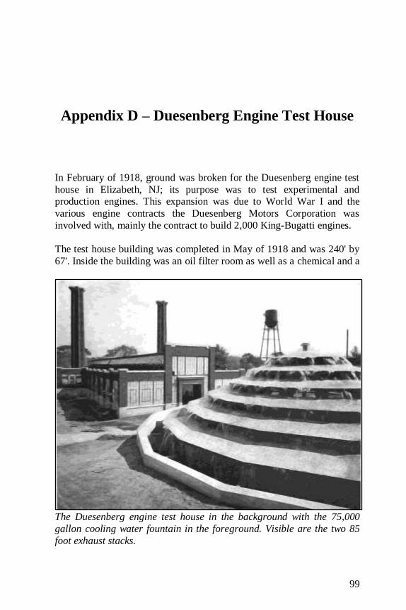
99
Appendix D – Duesenberg Engine Test House
In February of 1918, ground was broken for the Duesenberg engine test
house in Elizabeth, NJ; its purpose was to test experimental and production engines. This expansion was due to World War I and the
various engine contracts the Duesenberg Motors Corporation was
involved with, mainly the contract to build 2,000 King-Bugatti engines.
The test house building was completed in May of 1918 and was 240' by
67'. Inside the building was an oil filter room as well as a chemical and a
The Duesenberg engine test house in the background with the 75,000
gallon cooling water fountain in the foreground. Visible are the two 85
foot exhaust stacks.
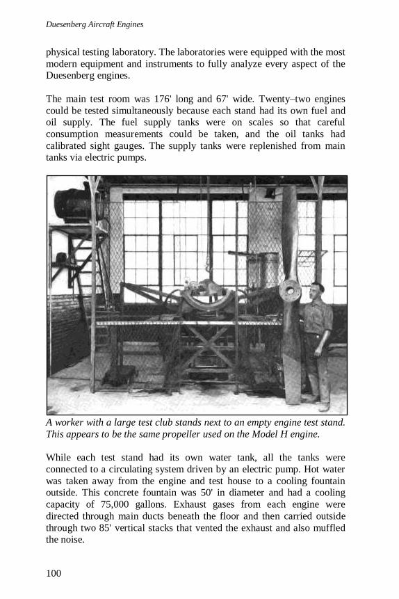
Duesenberg Aircraft Engines
100
physical testing laboratory. The laboratories were equipped with the most
modern equipment and instruments to fully analyze every aspect of the Duesenberg engines.
The main test room was 176' long and 67' wide. Twenty–two engines
could be tested simultaneously because each stand had its own fuel and oil supply. The fuel supply tanks were on scales so that careful
consumption measurements could be taken, and the oil tanks had
calibrated sight gauges. The supply tanks were replenished from main tanks via electric pumps.
A worker with a large test club stands next to an empty engine test stand.
This appears to be the same propeller used on the Model H engine.
While each test stand had its own water tank, all the tanks were
connected to a circulating system driven by an electric pump. Hot water
was taken away from the engine and test house to a cooling fountain outside. This concrete fountain was 50' in diameter and had a cooling
capacity of 75,000 gallons. Exhaust gases from each engine were
directed through main ducts beneath the floor and then carried outside
through two 85' vertical stacks that vented the exhaust and also muffled the noise.
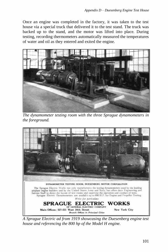
Appendix D – Duesenberg Engine Test House
101
Once an engine was completed in the factory, it was taken to the test
house via a special truck that delivered it to the test stand. The truck was backed up to the stand, and the motor was lifted into place. During
testing, recording thermometers automatically measured the temperatures
of water and oil as they entered and exited the engine.
The dynamometer testing room with the three Sprague dynamometers in
the foreground.
A Sprague Electric ad from 1919 showcasing the Duesenberg engine test house and referencing the 800 hp of the Model H engine.
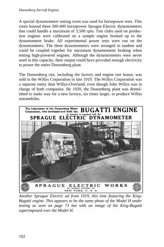
Duesenberg Aircraft Engines
102
A special dynamometer testing room was used for horsepower tests. This
room housed three 300-400 horsepower Sprague Electric dynamometers that could handle a maximum of 3,500 rpm. Test clubs used on produc-
tion engines were calibrated on a sample engine hooked up to the
dynamometer brake. All experimental power tests were run on the
dynamometers. The three dynamometers were arranged in tandem and could be coupled together for maximum dynamometer braking when
testing high-powered engines. Although the dynamometers were never
used in this capacity, their output could have provided enough electricity to power the entire Duesenberg plant.
The Duesenberg site, including the factory and engine test house, was sold to the Willys Corporation in late 1919. The Willys Corporation was
a separate entity than Willys-Overland, even though John Willys was in
charge of both companies. By 1920, the Duesenberg plant was demol-
ished to make way for a new factory, six times larger, to produce Willys automobiles.
Another Sprague Electric ad from 1919, this time featuring the King-
Bugatti engine. This appears to be the same photo of the Model H under testing as seen on page 73 but with an image of the King-Bugatti
superimposed over the Model H.

103
Appendix E – Christensen Self-Starter
Both the Duesenberg 16-valve, four-cylinder engine and the Model H
used Christensen self-starters. The Christensen self-starter was a novel solution to overcome some of the starting issues that troubled early
engines. Swinging the propeller by hand was always a dangerous and
ineffective way to start large aircraft engines.
The starter was designed by Niels Anton Christensen, an engineer
specializing in pneumatics, and built by the Christensen Engineering
Company out of Milwaukee, Wisconsin. The Christensen starter was composed of an air compressor, a carburetor, and an automatic distrib-
utor with one valve for each cylinder.
Christensen self-starter ad from 1917.

Duesenberg Aircraft Engines
104
The air compressor stored pressurized air in a tank located in the aircraft
fuselage. A three position control valve in the cockpit governed the operation of the starter. The first position was for starting the engine; the
second cut off air to the starter but allowed air from the tank to be used
for tire inflation; and the third was for operating the compressor, when
the engine was running, to fill the air tank. A button controlled cutout valve opened the line between the control valve and the air tank,
allowing air to flow from the tank to the starter or to the tank from the
compressor, depending on the position of the control valve.
Schematic showing the components of the Christensen self-starter.
When “Start Engine” was selected on the control valve and the cutout valve button was depressed, pressurized air flowed from the tank to a
special carburetor that was part of the starter and connected to the main
fuel supply. Fuel was then mixed with the air in the starter and fed to the
distributor. A cam driven from the engine opened valves in the distrib-utor through which the pressurized air/fuel mixture was sent to the
engine cylinders by firing order. Once the air/fuel mixture entered the
cylinder, it simulated the compression stroke, and the rich mixture was ignited by the spark plug. This process was repeated in the other
cylinders by firing order until the engine began to run on its own. A
check valve in the lead to each cylinder prevented a backfire into the distributor.
The air compressor was a single-cylinder, single-acting type driven by
any shaft on the engine. Through a clutch, the compressor could be
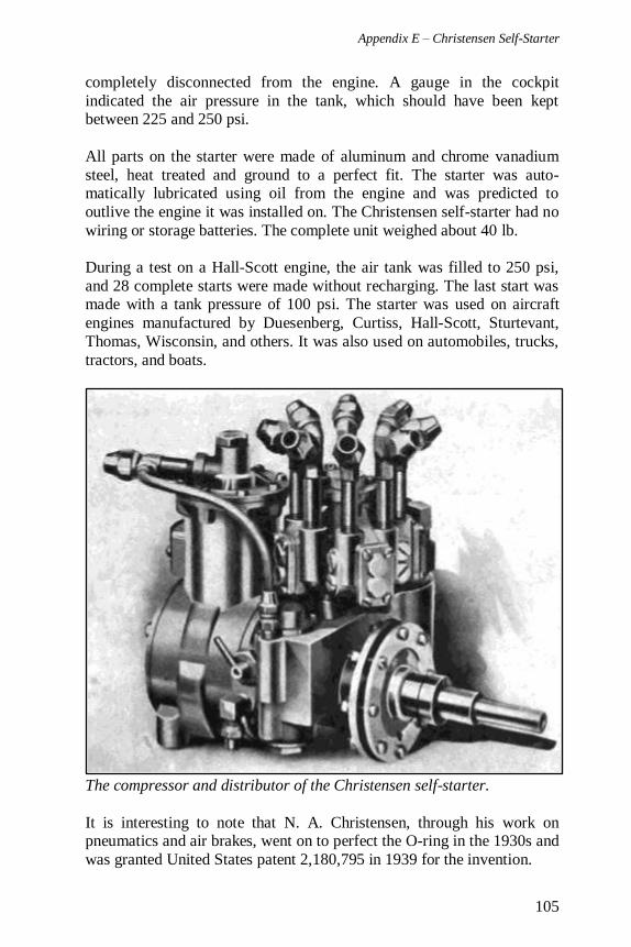
Appendix E – Christensen Self-Starter
105
completely disconnected from the engine. A gauge in the cockpit
indicated the air pressure in the tank, which should have been kept between 225 and 250 psi.
All parts on the starter were made of aluminum and chrome vanadium
steel, heat treated and ground to a perfect fit. The starter was auto-matically lubricated using oil from the engine and was predicted to
outlive the engine it was installed on. The Christensen self-starter had no
wiring or storage batteries. The complete unit weighed about 40 lb.
During a test on a Hall-Scott engine, the air tank was filled to 250 psi,
and 28 complete starts were made without recharging. The last start was made with a tank pressure of 100 psi. The starter was used on aircraft
engines manufactured by Duesenberg, Curtiss, Hall-Scott, Sturtevant,
Thomas, Wisconsin, and others. It was also used on automobiles, trucks,
tractors, and boats.
The compressor and distributor of the Christensen self-starter.
It is interesting to note that N. A. Christensen, through his work on pneumatics and air brakes, went on to perfect the O-ring in the 1930s and
was granted United States patent 2,180,795 in 1939 for the invention.
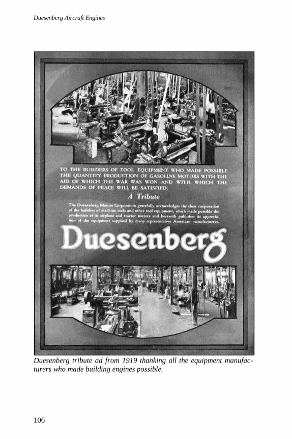
Duesenberg Aircraft Engines
106
Duesenberg tribute ad from 1919 thanking all the equipment manufac-
turers who made building engines possible.
107
Appendix F – Notes on Descriptions and
Conflicting Information
I generally prefer decimals over fractions. However, for readability and to present figures in the simplest way possible, fractions were a better
alternative, especially when dealing with numbers like 63/64. I used
fractions throughout the text but used decimals for the engine specifications and comparison chart.
I used the terms “left” and “right” several times to describe which side of
the engine various engine parts and equipment were located. In reference to this, the view is from standing behind the engine, where the front of
the engine (propeller end) is farthest from view, and the rear of the
engine (no propeller) is closest.
During my research, I occasionally found different figures for the same
engine. Some of these discrepancies were simply different power/rpm
combinations between a direct drive engine and a geared drive engine, both turning a fixed pitch propeller at the same speed. But conflicting
information extended beyond the engines. For example, many cannot
agree on whether F. Duesenberg’s first name was spelled Frederick, Frederic, Fredrick, Friedrich, etc. I tried to include only factual
information, but unfortunately, some mistakes may have been repeated.
In my humble opinion, the images of the first Duesenberg aircraft
engines, the Special A and the Special A3, look much more automotive
than they do aeronautic. In fact, they are remarkably similar to the engine
illustrated in the Duesenberg Internal Combustion Engine and Valve Gear patents of 1913 and 1914, respectively. I have to wonder if images
of these engines were originally referenced in publications as examples
of Duesenberg engines rather than as engines designed specifically for use in aircraft. Since images of these engines have made their way into
many publications as aircraft engines, and since I cannot say they were
not aircraft engines, I have included them in this book. However, I have
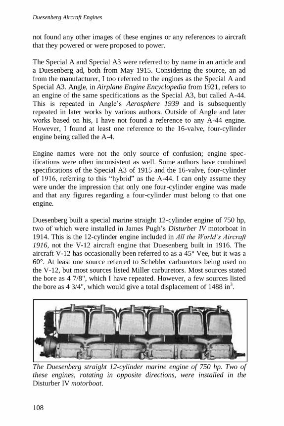
Duesenberg Aircraft Engines
108
not found any other images of these engines or any references to aircraft
that they powered or were proposed to power.
The Special A and Special A3 were referred to by name in an article and
a Duesenberg ad, both from May 1915. Considering the source, an ad
from the manufacturer, I too referred to the engines as the Special A and Special A3. Angle, in Airplane Engine Encyclopedia from 1921, refers to
an engine of the same specifications as the Special A3, but called A-44.
This is repeated in Angle’s Aerosphere 1939 and is subsequently repeated in later works by various authors. Outside of Angle and later
works based on his, I have not found a reference to any A-44 engine.
However, I found at least one reference to the 16-valve, four-cylinder engine being called the A-4.
Engine names were not the only source of confusion; engine spec-
ifications were often inconsistent as well. Some authors have combined specifications of the Special A3 of 1915 and the 16-valve, four-cylinder
of 1916, referring to this “hybrid” as the A-44. I can only assume they
were under the impression that only one four-cylinder engine was made and that any figures regarding a four-cylinder must belong to that one
engine.
Duesenberg built a special marine straight 12-cylinder engine of 750 hp,
two of which were installed in James Pugh’s Disturber IV motorboat in
1914. This is the 12-cylinder engine included in All the World’s Aircraft
1916, not the V-12 aircraft engine that Duesenberg built in 1916. The aircraft V-12 has occasionally been referred to as a 45° Vee, but it was a
60°. At least one source referred to Schebler carburetors being used on
the V-12, but most sources listed Miller carburetors. Most sources stated the bore as 4 7/8", which I have repeated. However, a few sources listed
the bore as 4 3/4", which would give a total displacement of 1488 in3.
The Duesenberg straight 12-cylinder marine engine of 750 hp. Two of these engines, rotating in opposite directions, were installed in the
Disturber IV motorboat.
Appendix F – Notes on Descriptions and Confliction Information
109
The King-Bugatti’s true weight was hard to pin down. Numbers vary
from 1,000 lb to 1,286 lb, and strangely, articles from the era often omitted the weight entirely or did not give the weight of the complete
engine. An engine weight of 1,248 lb dry and an additional 38 lb with
water in the jackets matches the 1,286 lb given by most modern sources,
such as the National Air and Space Museum.
Horsepower ratings for the King-Bugatti varied from 400 hp to 420 hp,
but typically a number of 410 hp at 2000 rpm is given. Because the focus of this work is on Duesenberg aircraft engines, and since the King-
Bugatti engine was not of Duesenberg design, I chose not to describe it
in as much detail as the other engines.
As for the Model H, most sources say there were four prototype engines.
However, The Bulletin of the Airplane Engineering Department stated
that the original contract of April 1918 was for two geared drive engines, but this contract was changed in June of 1918 to one geared drive engine
and one direct drive engine. The Bulletin makes no mention of more than
two 16-cylinder Duesenberg Model H engines being built, but it is possible that an additional two engines were built for the Navy.
Horsepower ratings for the Model H varied widely, from 700 hp to 900 hp. Most sources settled on 800 hp in reference to the geared version, but
some listed 800 hp in one place and 850 hp in another. It seems the
higher numbers were either obtained or thought to be obtainable at
engine speeds above 1,800 rpm. For the direct drive version, 700 hp was a common figure.
The “Duesenberg Sixteen-Cylinder Aircraft Engine” article from Automotive Industries dated January 23, 1917 was the source of the oil
pressure information for the Model H engine. The article stated that a
low pressure line was taken off from the main oil distributing line, and
oil pressure was reduced to “2/8” psi. This is oddly written and seems low. I did not include this figure in the engine description but wanted to
include it here for reference.
Again, it is not my intention to repeat incorrect information, but I’m sure
that this is unavoidable. I hope that someday someone will pick up where
I left off and complete a definitive/authoritative history of Duesenberg aircraft engines. These obscure, forgotten engines and the people who
created them deserved to be remembered.
Duesenberg Aircraft Engines
110
Duesenberg ad from 1919.

111
Bibliography
Angelucci, Enzo, and Peter Bowers. The American Fighter. Orion Books, 1987. Angle, Glenn D. Aerosphere 1939. Aircraft Publication, 1940.
Angle, Glenn D. Airplane Engine Encyclopedia. Otterbein Press, 1921.
Angle, Glenn D. “Progress Toward 1000 Hp. Aircraft Engines.” Aviation. 25
February 1924.
Borgeson, Griffith. The Golden Age of the American Racing Car (Second
Edition). Society of Automotive Engineers, 1998.
The Bulletin of the Airplane Engineering Department Vol. 1 & 2. Bureau of
Aircraft Production, 1918.
“The Christensen Self-Starter for Aerial Motors.” Aerial Age Weekly. 14
February 1916.
Clupper, Martt. “1919 Duesenberg Model H: V-16 Aircraft Engine.” AirPigz. 13
February 2010, http://airpigz.com/blog/2010/2/13/1919-duesenberg-model-h-v-16-aircraft-engine-amazing.html.
De Seta, Tony. “The Power of the Hour.” The Old Motor. 16 January 2011,
http://theoldmotor.com/?p=1832.
Dickey, Philip S., III. The Liberty Engine 1918-1942. Smithsonian Institution
Press, 1968.
“The Duesenberg Aero Engine.” Aerial Age Weekly. 29 January 1917.
“The Duesenberg Aero Engine.” Aviation and Aeronautical Engineering. 15
September 1916.
Duesenberg, F.S. and A.S. Duesenberg. Internal Combustion Engine. Patent
1,363,500. 28 December 1920.
Duesenberg, F.S. and A.S. Duesenberg. Valve Gear. Patent 1,244,481. 30 October 1917.
“Duesenberg Historical Highlights.” Keith Duesenberg & Leik Motorsports.
http://www.duesenberg-racing.com/historyauto.htm.
“The Duesenberg Model H.” Aerial Age Weekly. 3 March 1919.
“Duesenberg Motors Corp. v. United States - 260 U.S. 115 (1922).” Justia.com
US Supreme Court Center. http://supreme.justia.com/cases/federal/us/260/115/case.html.
“Duesenberg Sixteen-Cylinder Aircraft Engine.” Automotive Industries. 23
January 1919. “Fred S. Duesenberg, Pioneer High Duty Engine Builder.” Aerial Age Weekly.
25 November 1918.
Gordon, Robert A. “The Gallaudet D-1 and the Gallaudet Drive Aircraft.” The
Early Birds of Aviation, Inc. http://earlyaviators.com/ebjorkl1.htm.
Duesenberg Aircraft Engines
112
Greenlees, David. “The Duesenberg V-12 Aircraft Engine.” The Old Motor. 8
July 2011, http://theoldmotor.com/?p=23344.
Greenlees, David. “The Incredible V-16 Duesenberg Engine.” The Old Motor. 9
July 2011, http://theoldmotor.com/?p=23469.
Greenlees, David. “Sixteen Valves.” The Old Motor. 14 June 2011,
http://theoldmotor.com/?p=20330. Grey, C.G. All the World’s Aircraft 1916. Sampson Low, 1916.
Grey, C.G. All the World’s Aircraft 1917. Sampson Low, 1917.
Grey, C.G. All the World’s Aircraft 1918. Sampson Low, 1918.
Grey, C.G. All the World’s Aircraft 1919. Sampson Low, 1919.
Hourwich, Iskander and W.J.Foster. Air Service Engine Handbook. Engineering
Division U.S. Army Air Service, 1925.
“King-Bugatti 16-Cylinder Aero Engine” (Part I). Automotive Industries. 24
April 1919.
“King-Bugatti 16-Cylinder Aero Engine” (Part II). Automotive Industries. 1
May 1919.
“The King 550 Hp. Aircraft Engine.” Aviation and Aeronautical Engineering. 1 April 1919.
Knappen, Theodore Macfarlane. Wings of War. G. P. Putnam’s Sons, 1920.
Lewis, W. David. Eddie Rickenbacker. Johns Hopkins University Press, 2005.
“The M.F.P. Tractor Biplane.” Flight. 15 June 1916.
MacCoull, N. “Duesenberg Motors.” Aerial Age Weekly. 10 May 1915.
Molson, K.M. and H.A. Taylor. Canadian Aircraft Since 1909. Putnam, 1982.
Neal, Robert J. The Engineering Division W-1. Aircraft Engine Historical Society, 2009.
Neal, Robert J. Master Motor Builders. Aero-Marine History Publishing
Company, 2000.
“The New Duesenberg Aero Engine Test House.” Aerial Age Weekly. 23
September 1918.
“Orenco Commercial and Military Types.” Aerial Age Weekly. 29 March 1920.
Page, Victor W. Aviation Engines. Norman Henley Publishing Company, 1917.
Sherbondy, E.H., and G. Douglas Wardrop. Textbook of Aero Engines. Fredrick
A. Stokes Company, 1920.
Skinner, Sandy. “The U-16 Revisited.” Torque Meter: Journal of the Aircraft
Engine Historical Society Vol. 5 No. 3, Summer 2006.
Smith, Herschel. Aircraft Piston Engines. McGraw-Hill Inc., 1981. Smyth, Ross. The Lindbergh of Canada: The Erroll Boyd Story. General Store
Publishing House, 1997.
“Some American Aero Engines: The Duesenberg.” Flight. 10 September 1915.
Wagner, Ray. American Combat Planes of the 20th Century. Jack Bacon & Co.,
2004.
Wardrop, Douglas G. “The Duesenberg Model H 850 H.P. Motor.” Aerial Age
Weekly. 27 January 1919.
Wardrop, Douglas G. “The King-Bugatti Aviation Engine” (Part I). Aerial Age
Weekly. 10 February 1919.
Wardrop, Douglas G. “The King-Bugatti Aviation Motor” (Part II). Aerial Age
Weekly. 17 February 1919.


