Embed Size (px)
Citation preview
MINI PROJECT ON
CFD Analysis of a Rocket Nozzle with one Inlet at Mach 0.6
A Dissertation Submitted
In partial fulfillment of the requirement for the award of the degree of
Bachelor of Technology
In
AERONAUTICAL ENGINEERING
By
GANDIKOTA BABU VISHNU KISHORE (11N31A2135)
KAPARTHY AKASH (11N31A2154)
Under the Esteemed Guidance of
Mr. A.K.RAI
Professor
Department of Aeronautical Engineering
MALLA REDDY COLLEGE OF ENGINEERING AND TECHNOLOGY
DEPARTMENT OF AERONAUTICAL ENGINEERING
MALLA REDDY COLLEGE OF ENGINEERING AND TECHNOLOGY
(Affiliated to JNTU, Hyderabad)
ACCREDITED by AICTE-NBA Maisammaguda, Dhulapally post, Secunderabad-500014
DECLARATION
I hereby declare that the mini project entitled CFD Analysis of a Rocket Nozzle with
one Inlet at Mach 0.6 submitted to Malla Reddy College of Engineering and Technology,
affiliated to Jawaharlal Nehru Technological University Hyderabad (JNTUH) for the award
of the degree of Bachelor of Technology in Aeronautical Engineering is a result of original
research work done by us.
It is further declared that the project report or any part thereof has not been previously
submitted to any University or Institute for the award of degree or diploma.
GANDIKOTA BABU VISHNU KISHORE (11N31A2135)
KAPARTHY AKASH (11N31A2154)
CERTIFICATE
This is to certify that this is the bonafide record of the mini project titled CFD Analysis of a
Rocket Nozzle with one Inlet at Mach 0.6 submitted by GANDIKOTA BABU VISHNU KISHORE
(11N31A2135) and KAPARTHY AKASH (11N31A2154) of B.tech in the partial fulfillment of the
requirements for the degree of Bachelor of Technology in Aeronautical Engineering, Dept. of
Aeronautical Engineering during the year 2014 – 2015. The results embodied in this project
report have not been submitted to any other university or institute for the award of any degree
or diploma.
Mr. A.K.RAI Prof. T B S Rao
INTERNAL GUIDE M.Tech (P.hd)
HEAD OF THE DEPARTMENT
EXTERNAL EXAMINER

ACKNOWLEDGMENT:
The authors acknowledge the valuable suggestions from Prof. A.K RAI, Professor,
Department of aeronautical engineering, MRCET, India. The authors acknowledge the
suggestion and guidance provided by AICTE from the project and completion of our project.
INDEX:
1. NOZZLE…………………………………………………………………....…1
Introduction………………………………………………………………….1
Types of nozzles…………………………………………………………......3
Functions………………………………………………………………..…...7
2. ANSYS…………………………………………………………………………8
Introduction to Ansys………………………………………………………..8
Product overview…………………………………………………………….8
Products…………………………………………………………………….11
History…………………………………………………………………...…11
3. DE LAVAL NOZZLE ANALYSIS………………………………………….12
Introduction…………………………………………………………………12
Material and methods for mathematical model…………………………….12
Objective of present work…………………………………………………..13
Numerical methodology ………………………………………………….13
Computational model……………………………………………………..14
4. PROCEDURE FOR ANALYSIS OF DE LAVAL NOZZLE……….……15
5. SOLUTION…………………………………………………………………...18
6. CONCLUSION……………………………………………………………….26
7. REFERENCES………………………………………………………………27
ABSTRACT
De Laval nozzles are mechanical devices which are used to convert the thermal and pressure
energy into useful kinetic energy. The values of temperature, pressure and velocity should be
available at every section of the nozzle so as to design the nozzle shape, insulation and
cooling arrangements. This paper aims to calculate the velocity, pressure, temperature and
above and carried out analysis using the Computational Fluid Dynamics (CFD) software
ANSYS Fluent.
Keywords — De Laval nozzle, Theoretical equations, Computational Fluid Dynamics,
ANSYS Fluent.
1
1. NOZZLE:
The nozzle may be thought of as a device that converts enthalpy into kinetic energy
with no moving parts. A nozzle is used to give the direction to the gases coming out of the
combustion chamber. Nozzle is a tube with variable cross-sectional area. Nozzles are
generally used to control the rate of flow, speed, direction, mass, shape, and/or the pressure of
the exhaust stream that emerges from them. The nozzle is used to convert the chemical-
thermal energy generated in the combustion chamber into kinetic energy. The nozzle converts
the low velocity, high pressure, high temperature gas in the combustion chamber into high
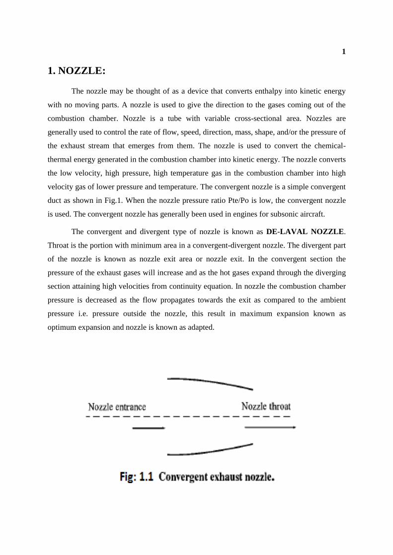
velocity gas of lower pressure and temperature. The convergent nozzle is a simple convergent
duct as shown in Fig.1. When the nozzle pressure ratio Pte/Po is low, the convergent nozzle
is used. The convergent nozzle has generally been used in engines for subsonic aircraft.
The convergent and divergent type of nozzle is known as DE-LAVAL NOZZLE.
Throat is the portion with minimum area in a convergent-divergent nozzle. The divergent part
of the nozzle is known as nozzle exit area or nozzle exit. In the convergent section the
pressure of the exhaust gases will increase and as the hot gases expand through the diverging
section attaining high velocities from continuity equation. In nozzle the combustion chamber
pressure is decreased as the flow propagates towards the exit as compared to the ambient
pressure i.e. pressure outside the nozzle, this result in maximum expansion known as
optimum expansion and nozzle is known as adapted.
2
3
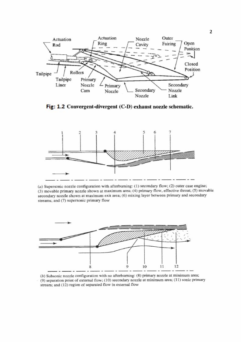
The convergent-divergent nozzle is used if the nozzle pressure ratio is high. High-
performance engines in supersonic aircraft generally have some form of a convergent-
divergent nozzle. If the engine incorporates an afterburner, the nozzle throat is usually
scheduled to leave the operating conditions of the engine upstream of the afterburner
unchanged in other words, the exit nozzle area is varied so that the engine doesn't know that
the afterburner is operating. Also, the exit area must be varied to match the internal and
external static pressures at exit for different flow conditions in order to produce the maximum
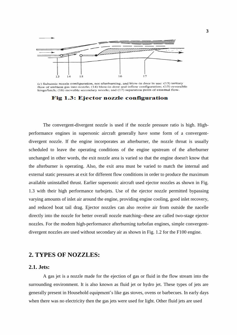
available uninstalled thrust. Earlier supersonic aircraft used ejector nozzles as shown in Fig.
1.3 with their high performance turbojets. Use of the ejector nozzle permitted bypassing
varying amounts of inlet air around the engine, providing engine cooling, good inlet recovery,
and reduced boat tail drag. Ejector nozzles can also receive air from outside the nacelle
directly into the nozzle for better overall nozzle matching--these are called two-stage ejector
nozzles. For the modem high-performance afterburning turbofan engines, simple convergent-
divergent nozzles are used without secondary air as shown in Fig. 1.2 for the F100 engine.
2. TYPES OF NOZZLES:
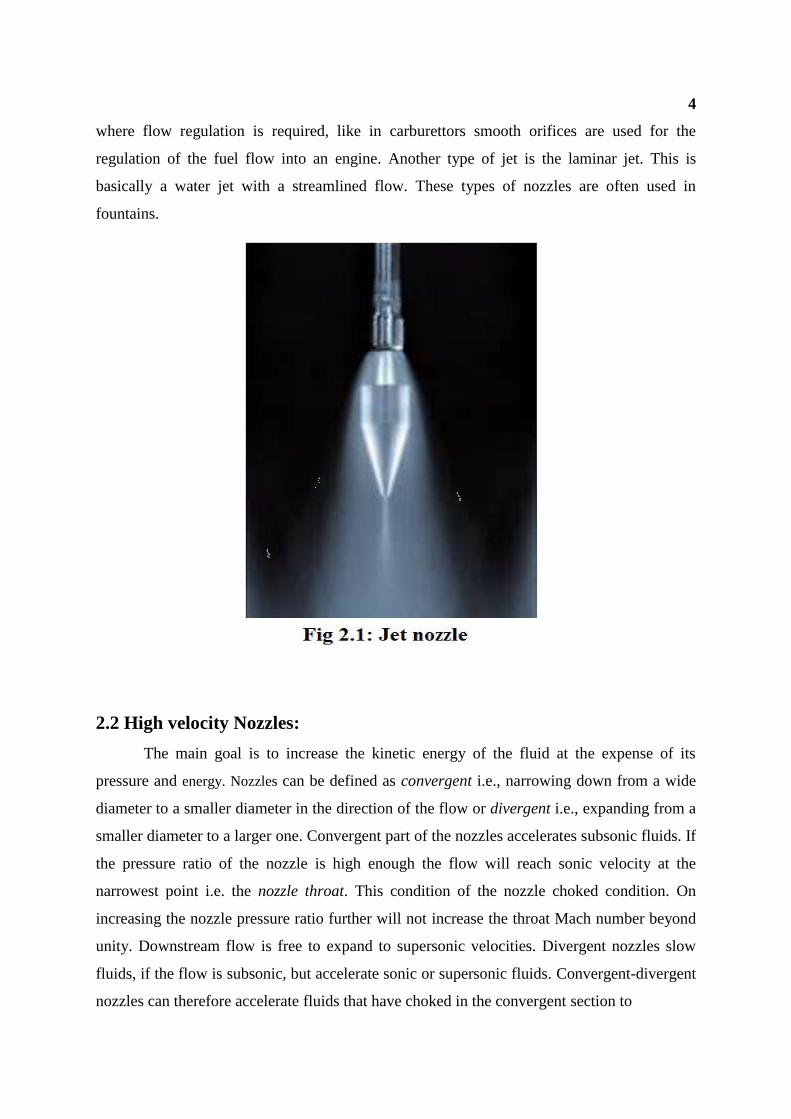
2.1. Jets:
A gas jet is a nozzle made for the ejection of gas or fluid in the flow stream into the
surrounding environment. It is also known as fluid jet or hydro jet. These types of jets are
generally present in Household equipment’s like gas stoves, ovens or barbecues. In early days
when there was no electricity then the gas jets were used for light. Other fluid jets are used
4
where flow regulation is required, like in carburettors smooth orifices are used for the
regulation of the fuel flow into an engine. Another type of jet is the laminar jet. This is
basically a water jet with a streamlined flow. These types of nozzles are often used in
fountains.
2.2 High velocity Nozzles:
The main goal is to increase the kinetic energy of the fluid at the expense of its
pressure and energy. Nozzles can be defined as convergent i.e., narrowing down from a wide
diameter to a smaller diameter in the direction of the flow or divergent i.e., expanding from a
smaller diameter to a larger one. Convergent part of the nozzles accelerates subsonic fluids. If
the pressure ratio of the nozzle is high enough the flow will reach sonic velocity at the
narrowest point i.e. the nozzle throat. This condition of the nozzle choked condition. On
increasing the nozzle pressure ratio further will not increase the throat Mach number beyond
unity. Downstream flow is free to expand to supersonic velocities. Divergent nozzles slow
fluids, if the flow is subsonic, but accelerate sonic or supersonic fluids. Convergent-divergent
nozzles can therefore accelerate fluids that have choked in the convergent section to
5
supersonic speeds. This process is more efficient than allowing a convergent nozzle to
expand supersonically externally. The shape of the divergent section also ensures that the
direction of the escaping gases is directly backwards, as any sideways component would not
contribute to thrust.
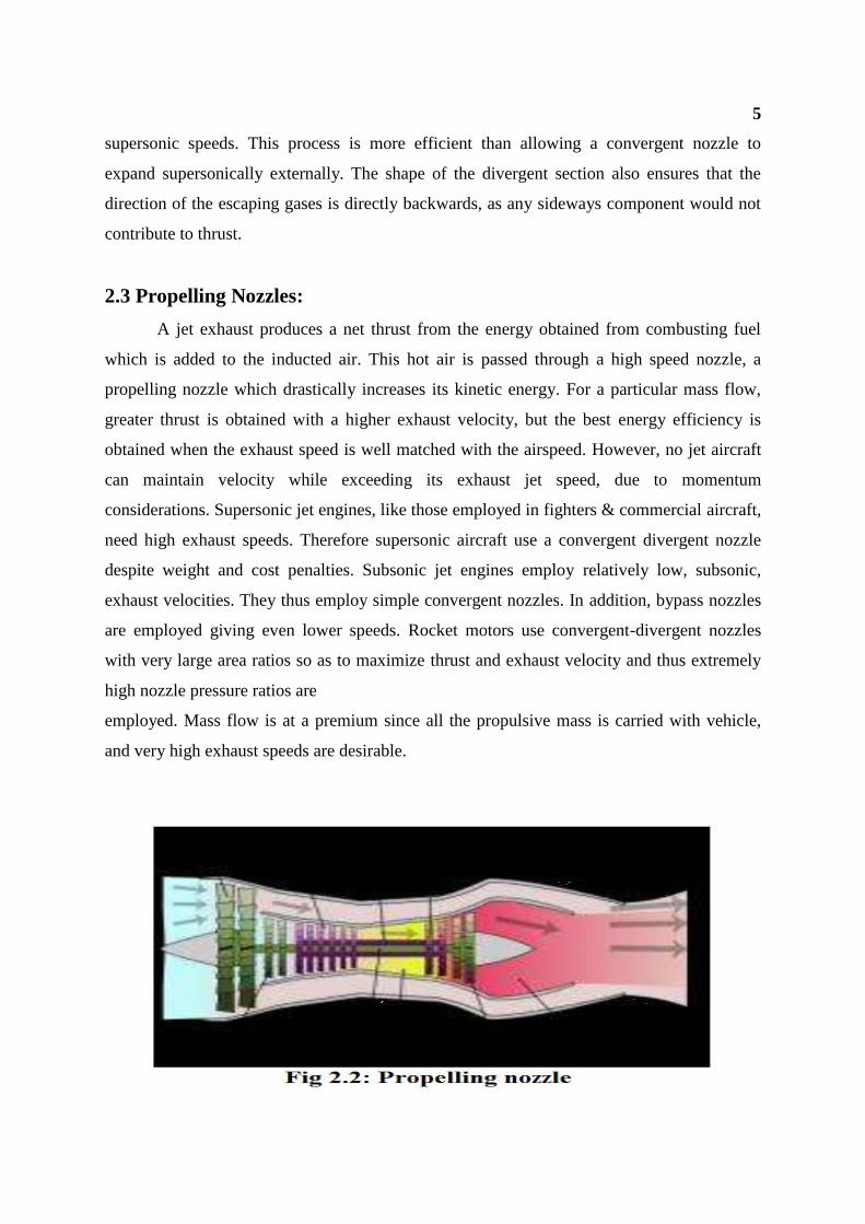
2.3 Propelling Nozzles:
A jet exhaust produces a net thrust from the energy obtained from combusting fuel
which is added to the inducted air. This hot air is passed through a high speed nozzle, a
propelling nozzle which drastically increases its kinetic energy. For a particular mass flow,
greater thrust is obtained with a higher exhaust velocity, but the best energy efficiency is
obtained when the exhaust speed is well matched with the airspeed. However, no jet aircraft
can maintain velocity while exceeding its exhaust jet speed, due to momentum
considerations. Supersonic jet engines, like those employed in fighters & commercial aircraft,
need high exhaust speeds. Therefore supersonic aircraft use a convergent divergent nozzle
despite weight and cost penalties. Subsonic jet engines employ relatively low, subsonic,
exhaust velocities. They thus employ simple convergent nozzles. In addition, bypass nozzles
are employed giving even lower speeds. Rocket motors use convergent-divergent nozzles
with very large area ratios so as to maximize thrust and exhaust velocity and thus extremely
high nozzle pressure ratios are
employed. Mass flow is at a premium since all the propulsive mass is carried with vehicle,
and very high exhaust speeds are desirable.
6
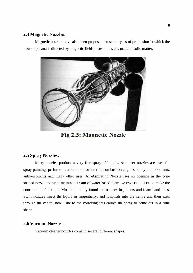
2.4 Magnetic Nozzles:
Magnetic nozzles have also been proposed for some types of propulsion in which the
flow of plasma is directed by magnetic fields instead of walls made of solid matter.
2.5 Spray Nozzles:
Many nozzles produce a very fine spray of liquids. Atomizer nozzles are used for
spray painting, perfumes, carburettors for internal combustion engines, spray on deodorants,
antiperspirants and many other uses. Air-Aspirating Nozzle-uses an opening in the cone
shaped nozzle to inject air into a stream of water based foam CAFS/AFFF/FFFP to make the
concentrate "foam up". Most commonly found on foam extinguishers and foam hand lines.
Swirl nozzles inject the liquid in tangentially, and it spirals into the centre and then exits
through the central hole. Due to the vortexing this causes the spray to come out in a cone
shape.
2.6 Vacuum Nozzles:
Vacuum cleaner nozzles come in several different shapes.
7
2.7 Shaping Nozzles:
Some nozzles are shaped to produce a stream that is of a particular shape. For
example extrusion moulding is a way of producing lengths of metals or plastics or other
materials with a particular cross-section. This nozzle is typically referred to as a die.
3. FUNCTIONS:
The purpose of the exhaust nozzle is to increase the velocity of the exhaust gas before
discharge from the nozzle and to collect and straighten the gas flow. For large values of
thrust, the kinetic energy of the exhaust gas must be high, which implies a high exhaust
velocity. The pressure ratio across the nozzle controls the expansion process and the
maximum uninstalled thrust for a given engine is obtained when the exit pressure (Pe) equals
the ambient pressure (P0).
The functions of the nozzle may be summarized by the following list:
1) Accelerate the flow to a high velocity with minimum total pressure loss.
2) Match exit and atmospheric pressure as closely as desired.
3) Permit afterburner operation without affecting main engine operation--requires
variable throat area nozzle.
4) Allow for cooling of walls if necessary.
5) Mix core and bypass streams of turbofan if necessary.
6) Allow for thrust reversing if desired.
7) Suppress jet noise, radar reflection, and infrared radiation (IR) if desired.
8) Two-dimensional and axisymmetric nozzles, thrust vector control if desired.
9) Do all of the above with minimal cost, weight, and boat tail drag while meeting
life and reliability goals.
8
4. ANSYS:
INTRODUCTION:
ANSYS Mechanical provides solutions for many types of analyses including
structural, thermal, modal, linear buckling and shape optimization studies. ANSYS
Mechanical is an intuitive mechanical analysis tool that allows geometry to be imported from
a number of different CAD systems. It can be used to verify product performance and
integrity from the concept phase through the various product design and development phases.
The use of ANSYS Mechanical accelerates product development by providing rapid feedback
on multiple design scenarios, which reduces the need for multiple prototypes and product
testing iterations.
Founded in 1970, ANSYS employs more than 2,700 professionals, and many of them
are engineers, expert in fields such as finite element analysis, computational fluid dynamics,
electronics and electromagnetic, and design optimization. Our staff includes more master’s
and Ph.D.-level engineers than any other simulation provider. ANSYS is passionate about
pushing the limits of world-class technology, all so our customers can turn their design
concepts into successful, innovative products. The company has been recognized as one of
the world's most innovative and fastest -growing companies by prestigious organizations
including Business Week and FORTUNE magazines. Over the years, our steady growth and
financial strength reflect our commitment to innovation and R&D. We reinvest 15 percent of
our revenues each year into research to continually refine our software. We are listed on the
NASDAQ stock exchange.
Products Overview:
ANSYS offers engineering simulation solution sets in engineering simulation that a
design process requires. Companies in a wide variety of industries use ANSYS software. The
tools put a virtual product through a rigorous testing procedure such as crashing a car into a
brick wall, or running for several years on a tarmac road before it becomes a physical object.
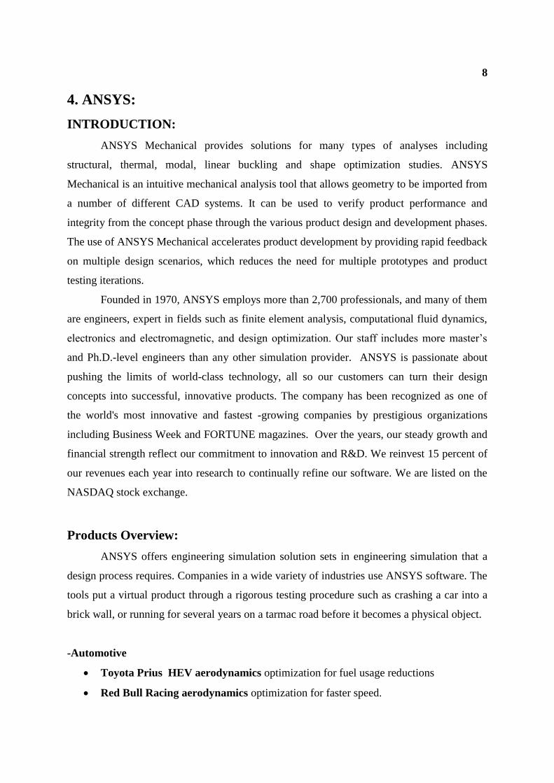
-Automotive
Toyota Prius HEV aerodynamics optimization for fuel usage reductions
Red Bull Racing aerodynamics optimization for faster speed.
9
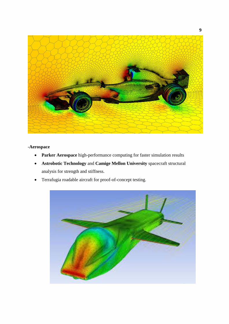
-Aerospace
Parker Aerospace high-performance computing for faster simulation results
Astrobotic Technology and Camige Mellon University spacecraft structural
analysis for strength and stiffness.
Terrafugia roadable aircraft for proof-of-concept testing.
10
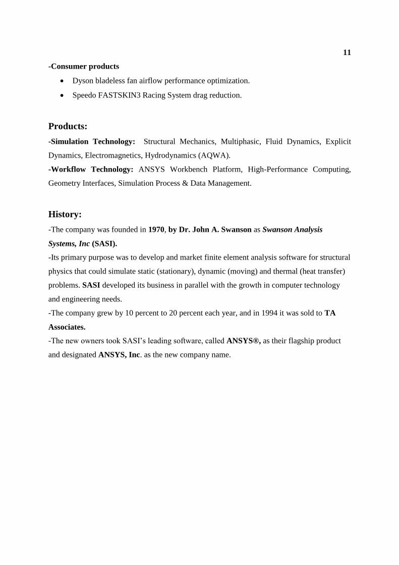
-Energy
Columbia Power wave energy device shape optimization to reduce maintenance
costs and breakdowns.
Indar Electric permanent magnet wind turbine generator optimization for reliable
operation.
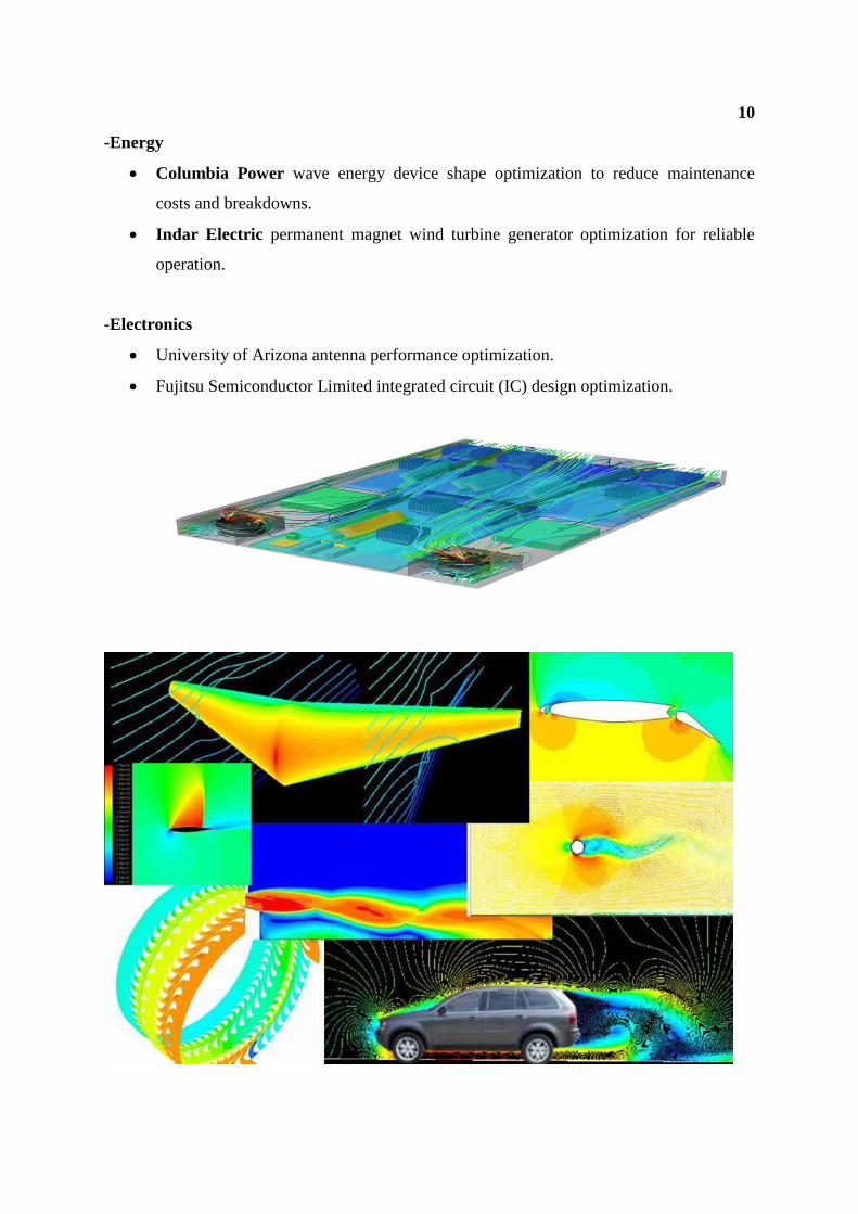
-Electronics
University of Arizona antenna performance optimization.
Fujitsu Semiconductor Limited integrated circuit (IC) design optimization.
11
-Consumer products
Dyson bladeless fan airflow performance optimization.
Speedo FASTSKIN3 Racing System drag reduction.
Products:
-Simulation Technology: Structural Mechanics, Multiphasic, Fluid Dynamics, Explicit
Dynamics, Electromagnetics, Hydrodynamics (AQWA).
-Workflow Technology: ANSYS Workbench Platform, High-Performance Computing,
Geometry Interfaces, Simulation Process & Data Management.
History:
-The company was founded in 1970, by Dr. John A. Swanson as Swanson Analysis
Systems, Inc (SASI).
-Its primary purpose was to develop and market finite element analysis software for structural
physics that could simulate static (stationary), dynamic (moving) and thermal (heat transfer)
problems. SASI developed its business in parallel with the growth in computer technology
and engineering needs.
-The company grew by 10 percent to 20 percent each year, and in 1994 it was sold to TA
Associates.
-The new owners took SASI’s leading software, called ANSYS®, as their flagship product
and designated ANSYS, Inc. as the new company name.
12
5. DE LAVAL NOZZLE ANALYSIS:
INTRODUCTION:
De Laval nozzle was invented by Gustaf de Laval, a Swedish inventor. It is a
converging-diverging type of nozzle, generally employed to provide supersonic jet velocity at
the exit of the nozzle. In this paper, analysis of De Laval nozzle is carried out theoretically by
formulating required nozzle equations and the results have been validated by computer
simulation using the CFD software ANSYS FLUENT. Firstly, velocity, temperature and
pressure have been calculated theoretically at different cross-sections of the nozzle using the
formulated equations. Secondly, the theoretical results are verified with the help of computer
simulation approach. De Laval found that the most efficient conversion occurred when the
nozzle first narrowed, increasing the speed of the jet to the speed of sound, and then
expanded again. Above the speed of sound this expansion caused a further increase in the
speed of the jet and led to a very efficient conversion of heat energy to motion.
The theory of air resistance was first proposed by Sir Isaac Newton in 1726.
According to him, an aerodynamic force depends on the density and velocity of the fluid, and
the shape and the size of the displacing object. Newton’s theory was soon followed by other
theoretical solution of fluid motion problems. All these were restricted to flow under
idealized conditions, i.e. air was assumed to possess constant density and to move in response
to pressure and inertia. Nowadays steam turbines are the preferred power source of electric
power stations and large ships, although they usually have a different design-to make best use
of the fast steam jet, de Laval’s turbine had to run at an impractically high speed. But for
rockets the de Laval nozzle was just what was needed.
MATERIAL AND METHODS FOR MATHEMATICAL MODEL:
A mathematical model comprises equations relating the dependent and the
independent variables and the relevant parameters that describe some physical phenomenon.
Typically, a mathematical model consists of differential equations that govern the behavior of
the physical system, and the associated boundary conditions. To start with fluent, it is
necessary to know if the meshed geometry is correct, so is checked. To ensue with, we are to
define the model, material, operating condition and boundary condition. Models are to be set
in order to define if any energy equation is dealt with our study, if the flow is viscous etc. We
have chosen coupled solver, 2d implicit, absolute velocity formulation, cell based gradient
13
option, superficial velocity porous formulation. As our flow is dealt with energy equation so
is necessary to check them up. The material is selected as air and the density as ideal gas to
make the solution simpler. Under the solve command the control is selected for limiting the
pressure to a maximum of 5e+7 and minimum of 1e+4. The initialization of value is
computed from the inlet. It is also necessary to select the appropriate approximation required
in the residual command under monitors and check in plot to visualize the progress of
iteration. Once every parameter is described the iteration is performed till the value gets
converged to required approximation. The figures can be plotted between position in x-axis
and any other function in y-axis from plot command or else to view vectors, contours or grid
display command is to be chosen.
OBJECTIVE OF PRESENT WORK:
The objective of the present work is to simulate supersonic flow through rocket
nozzle with combustion chamber to precisely understand the flow dynamics and variation of
flow properties in combustion chamber with the nozzle. This simulation is carried out using
fluent and gambit software. Gambit is used for generating the required mesh and simulation
done using fluent.
NUMERICAL METHODOLOGY:
A numerical method adopted to approximate the governing equations, along with the
relevant boundary conditions, by a system of linear algebraic equations is known as a
discretization method. Thus, a problem involving calculus is transformed into an algebraic
problem which can then be solved on a computer by using a solution methodology. A
discretization technique and solution methodology constitutes the numerical methodology
used to solve a heat transfer and fluid flow problem. There are many discretization methods,
but the most commonly used are the Finite difference method (FDM), the Finite volume
method (FVM) and the Finite element method (FEM). During the early days of
Computational fluid dynamics (CFD) finite-difference methods were the most popular.
They are algorithmically simple, efficient, and accurate. However, they are best used on
uniform grids and hence on regular computational domains. With advances of CFD, and its
application to industrial problems, there is a need for methods for computing flows in
complex geometries. To adapt the finite difference method to such geometries, we can map
14
the complex domain into simple domains, either globally or locally, and solve the equations
there. However, such transformation makes the governing equations take quite complicated
forms and may lead to a loss of computational efficiency and accuracy. Alternatively, one can
use schemes based on the finite volume methods directly on the physical domain i.e. without
transformation. Finite volume methods are essentially a generalization of the finite-difference
method, but use the integral form of the governing equations of flow rather than their
differential form. This gives greater flexibility in handling complex domains, as the finite
volumes need not be regular. The FLUENT code, which is used to simulate the flow field is
based on the finite volume discretization scheme and is one of the best application software
for this purpose.
COMPUTATIONAL MODEL:
This problem analyses the flow analysis of air and combustible gaseous mixture along the
inlet passage and exhaust passage of a turbojet engine. A divergent type of inletis taken and
the exhaust nozzle is convergent type. The mole fractions of each of the species are also
shown in the analysis. Enable physical models, define material properties
1. Define the domain as two dimensional, and keep the default (segregated) solver.
2. Enable the k-epsilon turbulence model.
3. Enable heat transfer by activating the energy equation.
4. Enable chemical species transport and reaction.
5. Initialize the field variable.
6. Turn on residual plotting during the calculation.
15
4. PROCEDURE FOR ANALYSIS OF DE LAVAL NOZZLE:
CFD is an engineering tool that assists experimentation. The following steps were
performed in CFD of nozzle: Modelling, meshing, pre-processing, solution, post-processing.
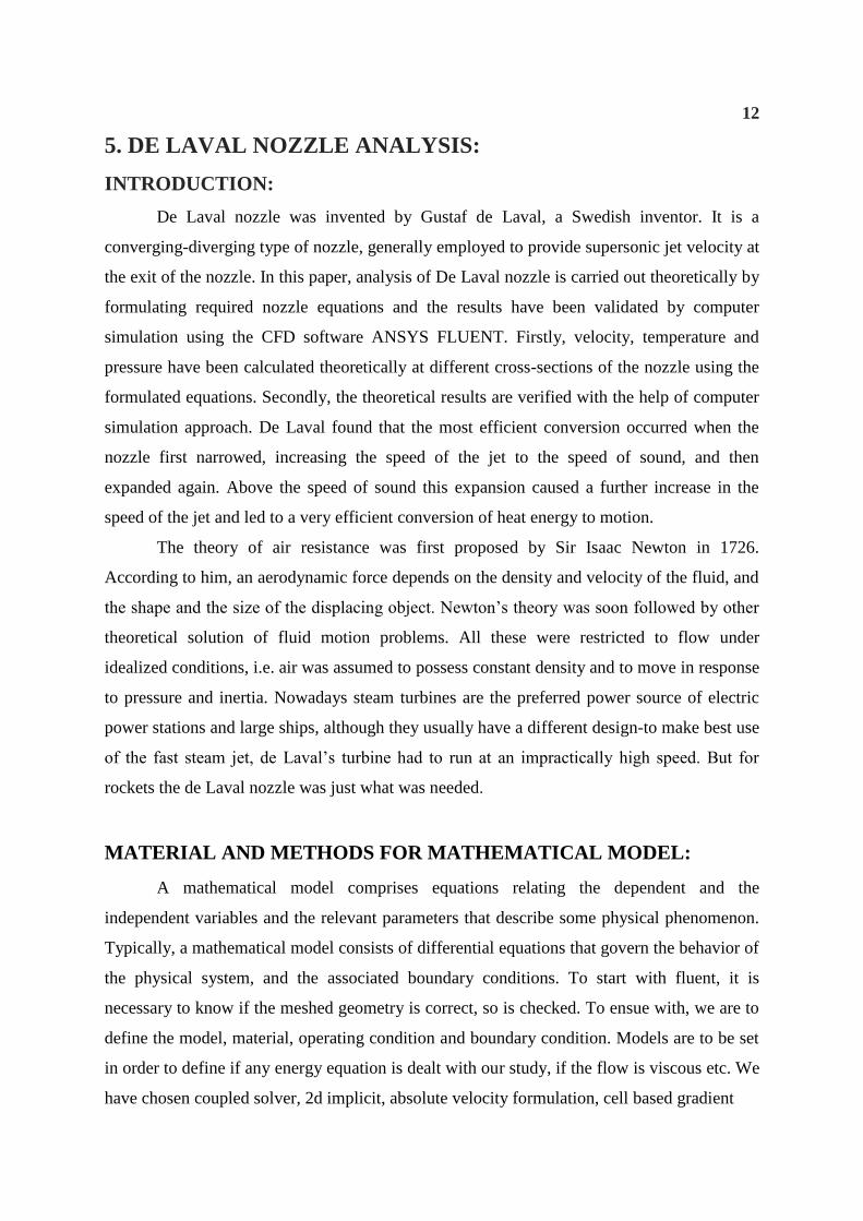
A. Modelling:
The 2-Dimensional modelling of the nozzle was done using ICEM CFD and file was
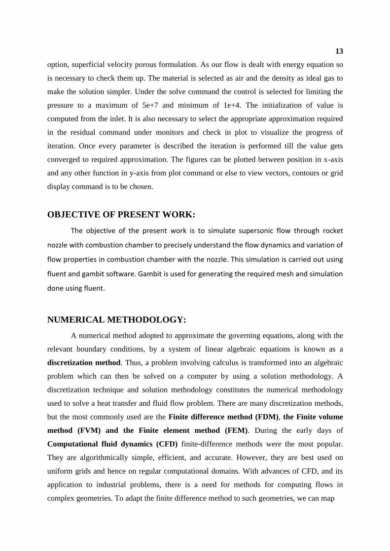
saved in .stp format. The dimensions of the de Laval nozzle are presented in the table given
below.
TABLE 1:
16
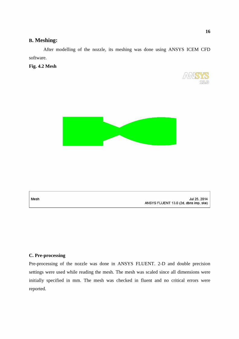
B. Meshing:
After modelling of the nozzle, its meshing was done using ANSYS ICEM CFD
software.
Fig. 4.2 Mesh
C. Pre-processing
Pre-processing of the nozzle was done in ANSYS FLUENT. 2-D and double precision
settings were used while reading the mesh. The mesh was scaled since all dimensions were
initially specified in mm. The mesh was checked in fluent and no critical errors were
reported.
17
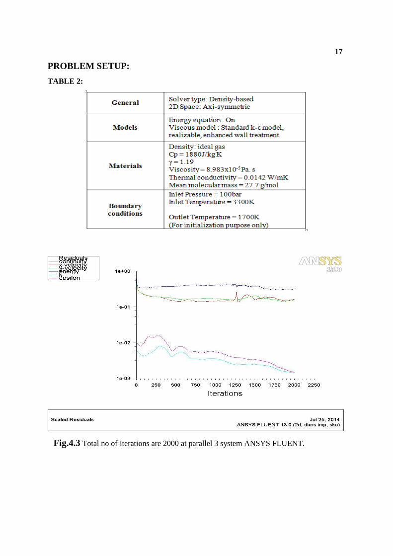
PROBLEM SETUP:
TABLE 2:
Fig.4.3 Total no of Iterations are 2000 at parallel 3 system ANSYS FLUENT.
18
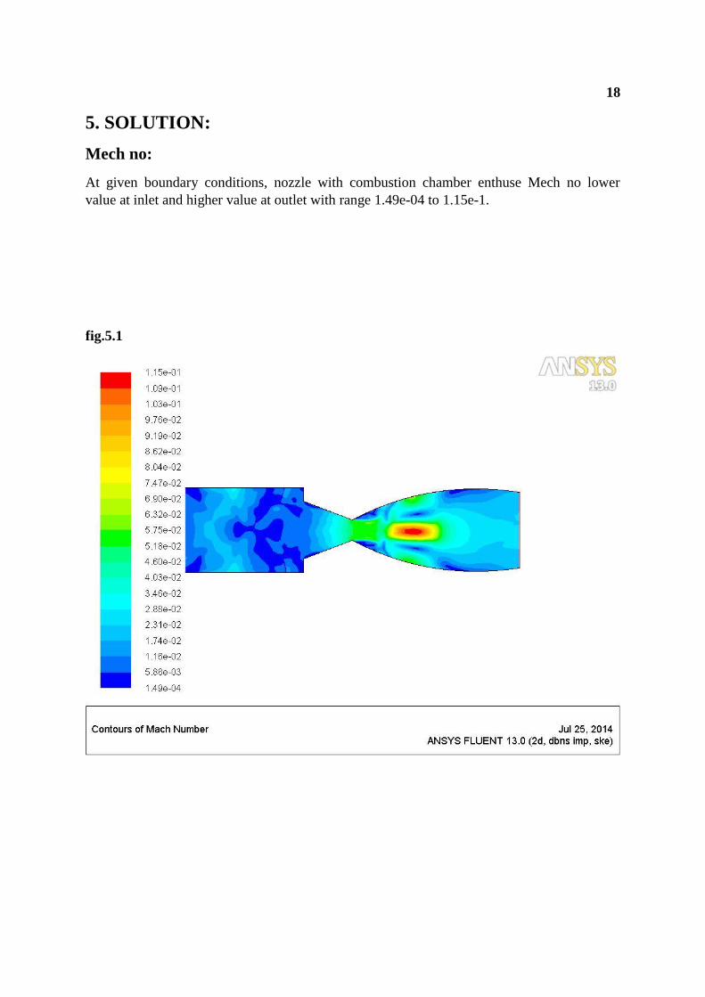
5. SOLUTION:
Mech no:
At given boundary conditions, nozzle with combustion chamber enthuse Mech no lower
value at inlet and higher value at outlet with range 1.49e-04 to 1.15e-1.
fig.5.1
19
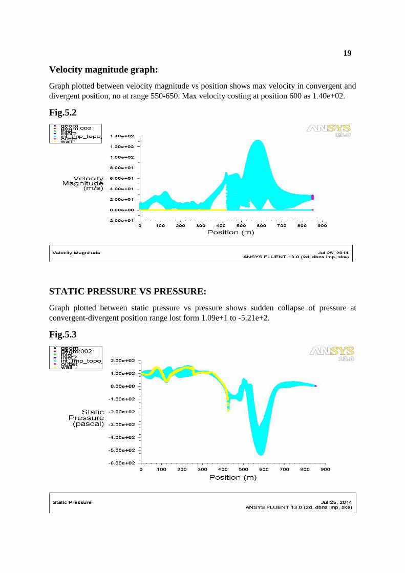
Velocity magnitude graph:
Graph plotted between velocity magnitude vs position shows max velocity in convergent and
divergent position, no at range 550-650. Max velocity costing at position 600 as 1.40e+02.
Fig.5.2
STATIC PRESSURE VS PRESSURE:
Graph plotted between static pressure vs pressure shows sudden collapse of pressure at
convergent-divergent position range lost form 1.09e+1 to -5.21e+2.
Fig.5.3
20
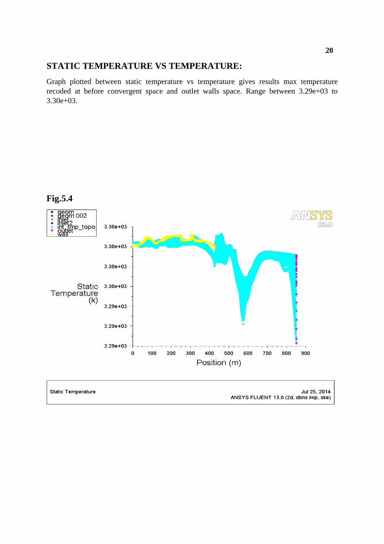
STATIC TEMPERATURE VS TEMPERATURE:
Graph plotted between static temperature vs temperature gives results max temperature
recoded at before convergent space and outlet walls space. Range between 3.29e+03 to
3.30e+03.
Fig.5.4
21
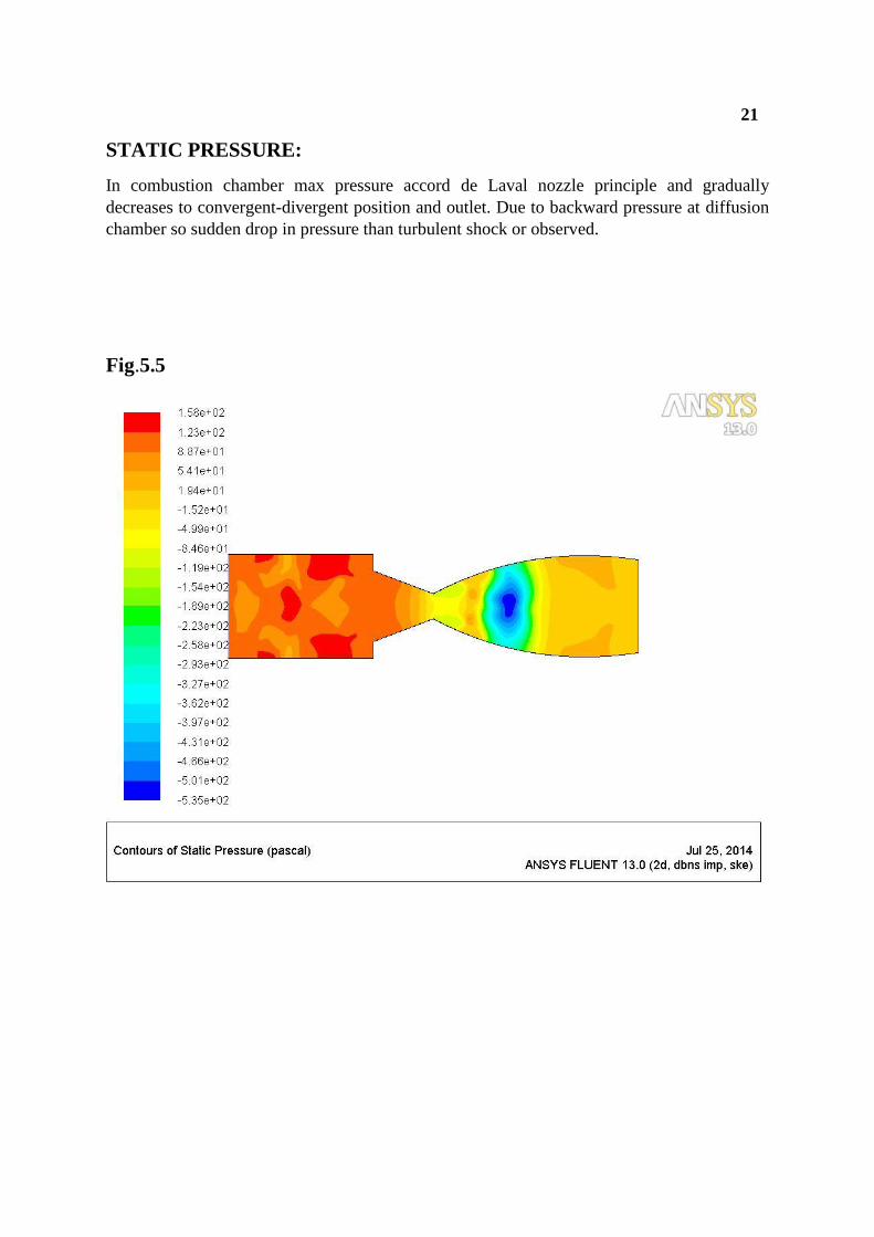
STATIC PRESSURE:
In combustion chamber max pressure accord de Laval nozzle principle and gradually
decreases to convergent-divergent position and outlet. Due to backward pressure at diffusion
chamber so sudden drop in pressure than turbulent shock or observed.
Fig.5.5
22
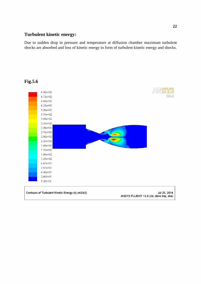
Turbulent kinetic energy:
Due to sudden drop in pressure and temperature at diffusion chamber maximum turbulent
shocks are absorbed and loss of kinetic energy in form of turbulent kinetic energy and shocks.
Fig.5.6
23
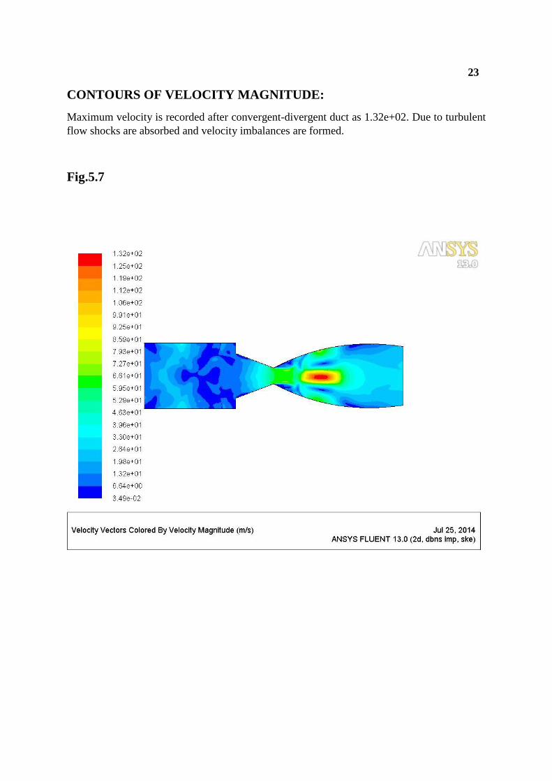
CONTOURS OF VELOCITY MAGNITUDE:
Maximum velocity is recorded after convergent-divergent duct as 1.32e+02. Due to turbulent
flow shocks are absorbed and velocity imbalances are formed.
Fig.5.7
24
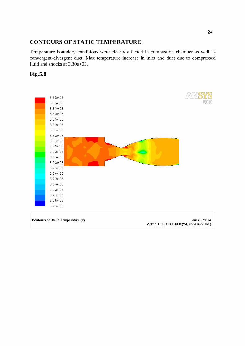
CONTOURS OF STATIC TEMPERATURE:
Temperature boundary conditions were clearly affected in combustion chamber as well as
convergent-divergent duct. Max temperature increase in inlet and duct due to compressed
fluid and shocks at 3.30e+03.
Fig.5.8
25
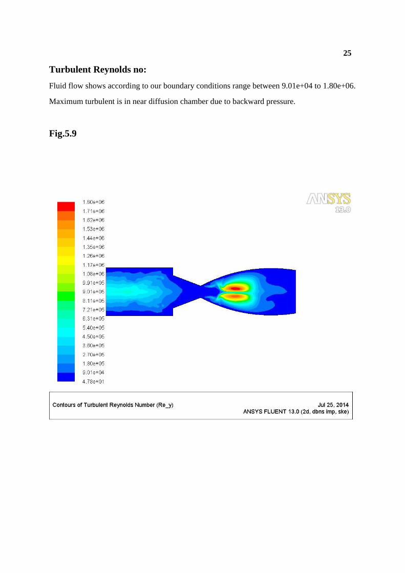
Turbulent Reynolds no:
Fluid flow shows according to our boundary conditions range between 9.01e+04 to 1.80e+06.
Maximum turbulent is in near diffusion chamber due to backward pressure.
Fig.5.9
26
6. CONCLUSION:
A model was developed to determine the pressure, temperature and flow distribution
in the combustion chamber region. The model includes various parameters of the jet and
ambient gas and can therefore be used for hot gases. Several steps of the model were
validated with good agreement with experimental data and numerical results found in the
literature. The maximum total pressure in the combustion chamber is 1.52e+02, and the
average total pressure in the combustion chamber is 1.92e+02, the average total pressure in
the conversion portion of the nozzle is 1.20e+02, while the average total pressure in
combustion chamber, pressure increase in combustion chamber and after that pressure goeson
decrease in the convergent portion and at the throat totalpressure is cover the negative value,
due to subsonic nozzle total pressure in the convergent part is less and velocity increases. The
average temperature in combustion chamber is 3.29e+03, and maximum temperature is
3.30e+03, the total temperature decrease in the divergent part of thenozzle compared the
combustion chamber and convergent part of the nozzle. When the fuel and air is enter in the
combustion chamber according to the x and y plot, its burn due to high velocity and
temperature and then temperature increase rapidly in combustion chamber and convergent
part of the nozzle and after that temperature decrease in the exitpart of the nozzle. A
maximum of 3.30e+03 is attained and beyond which the temperature steadily decreases.
Themaximum mass fraction of pentane is 1.00e-01 at the fuelinlet is attained beyond which
the mass fraction steadilydecrease, near to the wall mass fraction of pentane is zero.
27
REFERENCES:
[1] George P. Sutton and Oscar Biblarz, ―Rocket Propulsion Elements‖, A Wiley- Inter science
Publication, Seventh Edition, 2001,(pp 1-99).
[2] K. Ramamurthi, ―Rocket Propulsion‖, Macmillan publishers India, 2012 edition, (pp 54-89).
[3] K.M.Pandey and S.K.Yadav, ―CFD Analysis of a Rocket Nozzle with Two Inlets at Mach
.1‖,vJournal ofEnvironmental Research and Development, Vol 5, No 2,2010, (pp 308-321).
[4] Yunus A. Çengel and John M. Cimbala, ―Fluid Mechanics‖, Tata McGraw-Hill New York,
Second edition, (pp 853-910).
[5] BijuKuttan P and M Sajesh, "Optimization of Divergent Angle of a Rocket Engine Nozzle Using
Computational Fluid Dynamics", The International Journal Of Engineering And Science (Ijes),
Volume 2,
No 2, 2013, pp 196-207.


