Embed Size (px)
Citation preview
LARGE LIQUID ROCKET ENGINE
TRANSIENT PERFORMANCE
SIMULATION SYSTEM
FINAL REPORT
Prepared for
NASA-George C. Marshall Space Flight Center
Marshall Space Flight Center, Alabama 35812
Prepared Under
United Technologies Corporation
Pratt & WhitneyGovernment Engine Business
P.O. Box 109600,
West Palm Beach, FL 33410-9600
J. R. Mason
P&W Program Manager
R. D. Southwick
Propulsion Systems
Technology Manager
https://ntrs.nasa.gov/search.jsp?R=19910011919 2020-03-19T19:09:08+00:00Z

FOREWORD
Pratt& Whitney, Government Engine Business of United Technologies Corporation
conducted this program for the National Aeronautics and Space Administration, George C.
Marshall Space Flight Center under contract NAS8-36994. The NASA project manager for
this contract was Mr. W.A. Adams, Jr. of the MSFC, mechanical systems control branch.
The P&W program manager was Mr. J.R. Mason with technical contributions of Mr. D.L.
Baker, Mr. C.R. Byrd, Mr. T.F. Denman, Mr. H. P. Frankl, Mr. S.M. Mericle, Mr. R.W.
Parham, Mr. J.W. Park, Mr. J.E. Pollard, Mr. T.J. Roadinger, Mr. RoS. Rosson, Mr. M.H.
Sabatella, Mr. D.H.Spear, Mr. J.P. Spinn, and Mr. P.W. McLaughlin of "The Simulation and
Modeling Workshop".
1.0
2.0
3.0
4.0
5.0
6.0
7.0
8.0
9.0
CONTENTS
SUMMARY ..............................................................
INTRODUCTION ..........................................................
SYSTEM DESCRIPTION ....................................................
Paae
1
3
7
TTBE MODEL ............................................................ 27
SYSTEM TESTING AND VERIFICATION ....................................... 49
CONTRACT END ITEMS ................................................... 107
CONCLUSIONS .......................................................... 113
RECOMMENDATIONS ........... . ......................................... 115
REFERENCES ........................................................... 117
APPENDIX A - USER'S MANUAL .................................................. 119
APPENDIX B - EXAMPLE PUMP MODULE ........................................... 151
APPENDIX C - INTERFACED NASA CONTROL MODEL ................................. 163
APPENDIX D - TTBE MODEL CONFIGURATION INPUT ................................. 177
SECTION I
SUMMARY
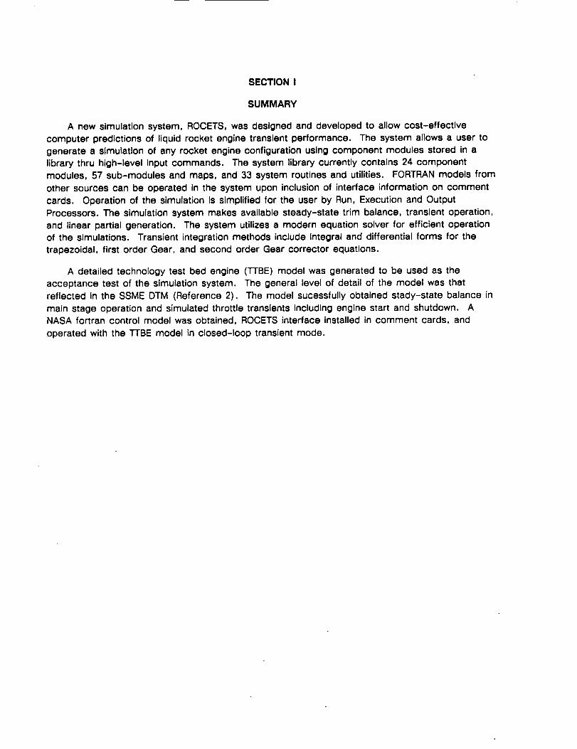
A new simulation system, ROCETS, was designed and developed to allow cost-effective
computer predictions of liquid rocket engine transient performance. The system allows a user to
generate a simulation of any rocket engine configuration using component modules stored in a
library thru high-level input commands. The system library currently contains 24 component
modules, 57 sub-modules and maps, and 33 system routines and utilities. FORTRAN models from
other sources can be operated in the system upon inclusion of interface information on comment
cards. Operation of the simulation Is simplified for the user by Run, Execution and Output
Processors. The simulation system makes available steady-state trim balance, transient operation,
and linear partial generation. The system utilizes a modern equation solver for efficient operation
of the simulations. Transient integration methods include integral and differential forms for the
trapezoidal, first order Gear, and second order Gear corrector equations.
A detailed technology test bed engine (TTBE) model was generated to be used as the
acceptance test of the simulation system. The general level of detail of the model was that
reflected in the SSME DTM (Reference 2). The model sucessfully obtained stady-state balance in
main stage operation and simulated throttle transients including engine start and shutdown. A
NASA fortran control model was obtained, ROCETS interface installed in comment cards, and
operated with the ]-IBE model in closed-loop transient mode.

This page left intentionally blank.
2
SECTION II
INTRODUCTION
The National Aeronautics and Space Administration (NASA) Facilities such as the George C.
Marshall Space Flight Center (MSFC) require analysis and simulation of pump fed liquid rocket
engine transient performance. The types of analysis and simulation include control design and
analysis, design parametric studies, research and development, failure investigation, real-time
simulation, feasibility studies, and software design, development, and testing. Therefore, multiple
simulations representing different engine configurations with various levels of fidelity and transient
response ranges are needed to support these studies. An analytical tool to meet these needs in a
cost-effective manner is a digital computer simulation system.
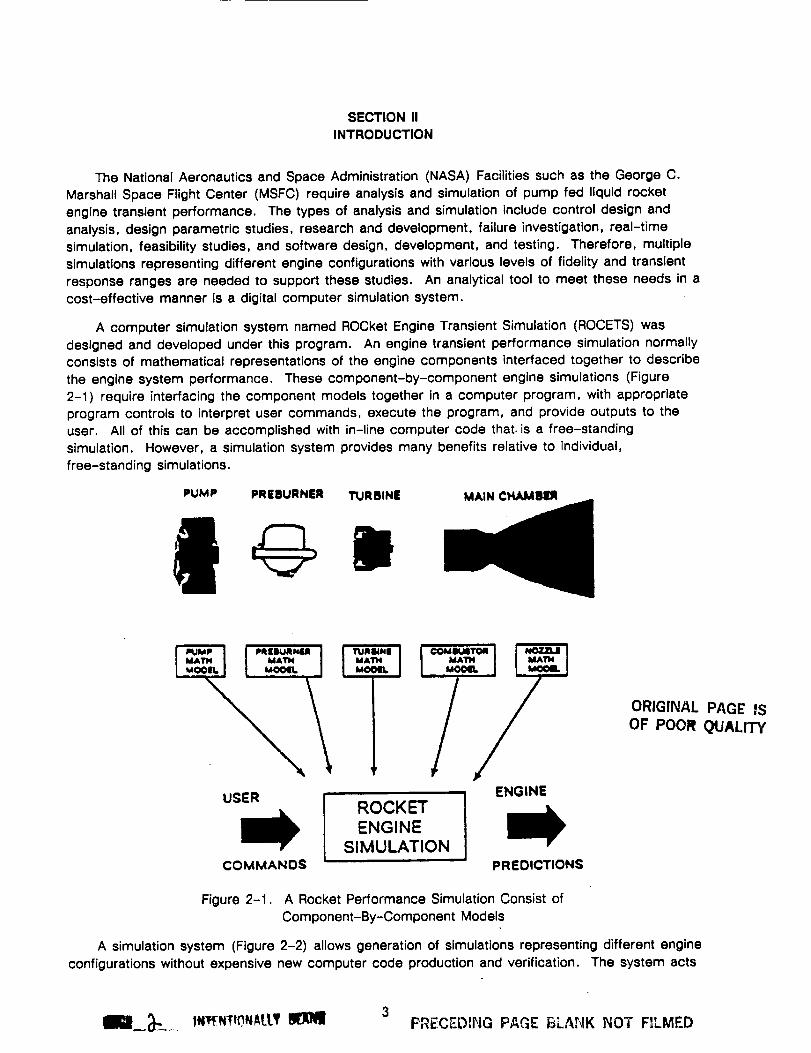
A computer simulation system named ROCket Engine Transient Simulation (ROCETS) was
designed and developed under this program. An engine transient performance simulation normally
consists of mathematical representations of the engine components interfaced together to describe
the engine system performance. These component-by-component engine simulations (Figure
2-1) require interfacing the component models together in a computer program, with appropriate
program controls to interpret user commands, execute the program, and provide outputs to the
user. All of this can be accomplished with in-line computer code that is a free-standing
simulation. However, a simulation system provides many benefits relative to individual,
free-standing simulations.
PUMP PRigURNER TURBINE MAIN CHAMIII_
USER ENGINEROCKET
ENGINE
SIMULATIONCOMMANDS PREDICTIONS
ORIGINAL PAGE ISOF POOR OUALI'W
Figure 2-1. A Rocket Performance Simulation Consist of
Component-By-Component Models
A simulation system (Figure 2-2) allows generation of simulations representing different engine
configurations without expensive new computer code production and verification. The system acts
3___.._., IN_NIIr).NAU.T_ PRECEDiI"IG PAGE BLANK NOT F!LMED
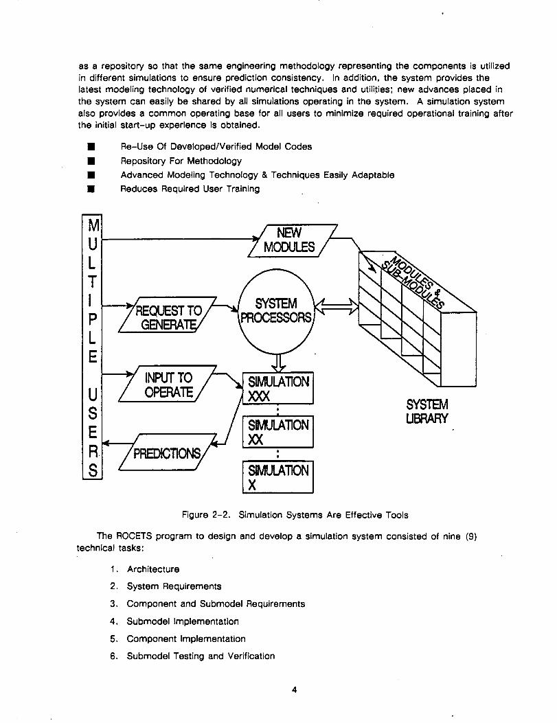
as a repository so that the same engineering methodology representing the components is utilized
in different simulations to ensure prediction consistency. In addition, the system provides the
latest modeling technology of verified numerical techniques and utilities; new advances placed in
the system can easily be shared by all simulations operating in the system. A simulation system
also provides a common operating base for all users to minimize required operational training after
the initial start-up experience is obtained.
• Re-Use Of Developed/Verified Model Codes
• Repository For Methodology
• Advanced Modeling Technology & Techniques Easily Adaptable
• Reduces Required User Training
/7 MODULES
s_ .ONIFigure 2-2. Simulation Systems Are Effective Tools
The ROCETS program to design and develop a simulation system consisted of nine (9)
technical tasks:
1. Architecture
2. System Requirements
3. Component and Submodel Requirements
4. Submodel Implementation
5. Component Implementation
6. Submodel Testing and Verification
4
7. Subsystem Testing and Verification
8. TTBE Model Data Generation
9. System Testing & Verification
The Architecture definition determined there would be five major components of the ROCETS
system:
1.
2.
3.
4.
5.
Library System
Executive programs (or Processors)
Simulation Input and Output
Documentation
Maintenance Procedures
The requirements were developed and documented in the System Requirements Specification
(SRS) of P&W FR-20283, 25 November 1988 (Reference 3). The component and submodelimplementation and testing/verification is contained in the System Design Specification (SDS) ofP&W FR-20284, 25 July 1990 (Reference 4). The Technology Test Bed Engine (TTBE) Model
description and system testing/verification are contained in this report.
5

This page left intent!onally blank.
SECTION III
SYSTEM DESCRIPTION
The Rocket Engine Transient Simulation (ROCETS) System was designed to use modular
building blocks to represent engine components, and an architecture to interface these modules in
any configuration desired by the user when generating an engine simulation. The architecture
structure does not include any specific rocket engine configuration, and thus the flexibility exists to
configure any rocket cycle of the future. The five components of the ROCETS system are:
1. Library - A central source of all software code to allow multiple-users.
2. Executive Programs - Software processors that conduct system functions.
3. Simulation Input/Output - User inputs to configure a simulation, to execute the
simulation, and to output the desired parameters.
4. Documentation - System standards, engineering descriptions, user's manual,programmers manual, and qualification test plants (contained in FR-20284).
5. Maintenance Procedures - Instructions for system upkeep (contained in
FR-20284).
3.1 SYSTEM OVERVIEW
The ROCETS System has engineering models of all major engine components which are
implemented as FORTRAN subroutines. These subroutines are called "modules". Standard
engineering modules, once fully verified and documented, are put into a library so they can be
accessed by all system users. A unique aspect of the ROCETS system is that engineering
modules use comment cards to interface with the system. This allows ROCETS modules to be
used outside the system as well as the ability to quickly adapt existing code to be used inside the
system.
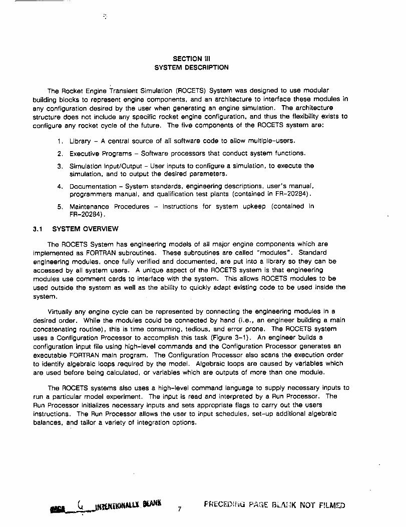
Virtually any engine cycle can be represented by connecting the engineering modules in a
desired order. While the modules could be connected by hand (i.e., an engineer building a main
concatenating routine), this is time consuming, tedious, and error prone. The ROCETS system
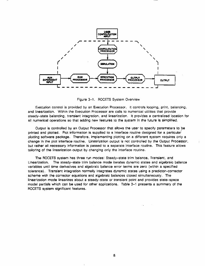
uses a Configuration Processor to accomplish this task (Figure 3-1). An engineer builds a
configuration input file using high-level commands and the Configuration Processor generates an
executable FORTRAN main program. The Configuration Processor also scans the execution order
to identify algebraic loops required by the model. Algebraic loops are caused by variables which
are used before being calculated, or variables which are outputs of more than one module.
The ROCETS systems also uses a high-level command language to supply necessary inputs to
run a particular model experiment. The input is read and interpreted by a Run Processor. The
Run Processor initializes necessary inputs and sets appropriate flags to carry out the users
instructions. The Run Processor allows the user to input schedules, set-up additional algebraic
balances, and tailor a variety of integration options.
PRECEL')II:=G PAGE BLA,r;K NOT F!LMF.D
//
//
RUNPROC|IIIIOR
\\
\
I
I
OUTPUt'
Figure 3-1. ROCETS System Overview
Execution control is provided by an Execution Processor. It controls looping, print, balancing,and linearization. Within the Execution Processor are calls to numerical utilities that providesteady-state balancing, transient integration, and linearization. It provides a centralized location forall numerical operations so that adding new features to the system in the future is simplified.
Output is controlled by an Output Processor that allows the user to specify parameters to beprinted and plotted. Plot information is supplied to a interface routine designed for a particularplotting software package. Therefore, implementing plotting on a different system requires only a
change in the plot interface routine. Linearization output is not controlled by the Output Processor,but rather all necessary information is passed to a separate interface routine. This feature allowstailoring of the linearization output by changing only the interface routine.
The ROCETS system has three run modes: Steady-state trim balance, Transient, andLinearization. The steady-state trim balance mode iterates dynamic states and algebraic balancevariables until time derivatives and algebraic balance error terms are zero (within a specifiedtolerance). Transient integration normally integrates dynamic states using a predictor-correctorscheme with the corrector equations and algebraic balances closed simultaneously. Thelinearization mode linearizes about a steady-state or transient point and provides state-spacemodel partials which can be used for other applications. Table 3-1 presents a summary of theROCETS system significant features.
,o
]Jb.r.a_
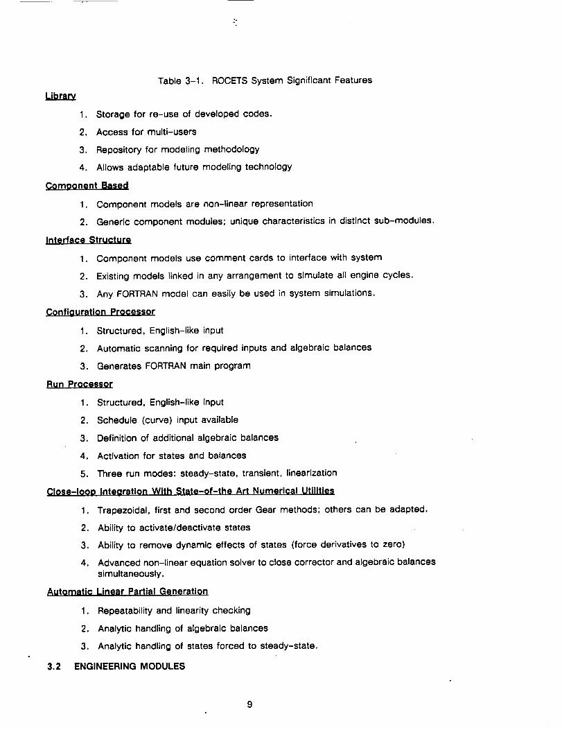
Table 3-1. ROCETS System Significant Features
1. Storage for re-use of developed codes.
2. Access for multi-users
3. Repository for modeling methodology
4. Allows adaptable future modeling technology
Comgonent Based
1. Component models are non-linear representation
2. Generic component modules; unique characteristics in distinct sub-modules.
Interface Structure
1. Component models use comment cards to interface with system
2. Existing models linked in any arrangement to simulate all engine cycles,
3. Any FORTRAN model can easily be used in system simulations.
Configuration Processor
1. Structured, English-like input
2. Automatic scanning for required inputs and algebraic balances
3. Generates FORTRAN main program
Run Processor
1. Structured, English-like input
2. Schedule (curve) input available
3. Definition of additional algebraic balances
4. Activation for states and balances
5. Three run modes: steady-state, transient, linearization
CIose-looD Intearation With State-of-the Art Numerical Utilities
1. Trapezoidal, first and second order Gear methods; others can be adapted.
2. Ability to activate/deactivate states
3. Ability to remove dynamic effects of states (force derivatives to zero)
4. Advanced non-linear equation solver to close correctcr and algebraic balances
simultaneously,
Linear Partial Generation
Repeatability and linearity checking
Analytic handling of algebraic balances
3. Analytic handling of states forced to steady-state.
ENGINEERING MODULES
A_Itomatic
1.
2.
3.2
Engineeringmodules are stand-alone engineering representations of individual entities that are
singular in purpose. The modular approach separates engineering modules, sub-modules,
component data and generic data (properties) into the basic building blocks of the simulation. For
example, a generic turbine module can be used multiple times in a single simulation simply by
changing the component performance characteristics or map as well as being used in multiple
simulations. This reduces the amount of code required while providing consistent methodology.
The approach taken in modeling gives primary preference to engineering first principals
followed by empirical correlations and transfer functions. However, modules of similar functions
can be built with different modeling approaches and varying levels of complexity. The user then
has the flexibility to select different approaches and level of detail used in a simulation.
During the design phase of ROCETS, it was evident that the use of existing engineering
representations would be desirable. To achieve this goal, it was decided to separate system
functions from the engineering representations. This was accomplished by using call lists for
communication to the engineering modules and keeping all system dependent code out of the
individual modules. An additional benefit is that the modules can be operated as individual entities
during design and verification. Modules only communicate to the ROCETS system through the
subroutine call list. Commons are not used to communicate with the main or other modules.
However, common blocks can be used in certain cases for communication between a module and
a sub-module.
Modules are interfaced to the ROCETS system using three blocks of comment cards at the
beginning of the subroutine. These comment card blocks are called "interface cards" and are
read by the Configuration Processor. The interface blocks relate call list names to system names,
define the status of each variable for system operation, define the I/O status of each variable, and
the FORTRAN variable type. Virtually any FORTRAN subroutine can easily be converted to the
ROCETS system by adding the interface information on comment cards. However, the module
history including author, dated revisions and internal code documentation should also be included.
3.3 TRANSIENT MODELLING ASPECTS
In general, the dynamics which are modelled in a rocket engine consist of volume dynamics,
flow inertia, rotor speed integration, and thermal capacitance. Volume dynamics implement the
laws of conservation of mass and energy using density and internal energy as dynamic states.
Flow inertia dynamics implement conservation of momentum using flow rate as the dynamic state.
Thermal nodes implement heat transfer laws and the energy equation applied to a metal mass
using the metal temperature as the dynamic state.
The baseline transient integration scheme is a predictor-corrector with the corrector equations
closed by a modified Newton-Raphson iteration. Using a closed-loop integration offers advantages
which are incorporated into the system. One item of particular usefulness is the capability of
forcing states to their steady-state value during a transient. This is accomplished by using a
steady-state error term (i.e., forcing the time derivative to zero) instead of closing the corrector
equation for specified states. When this is done, the dynamic effects of the specified states are
removed thereby allowing a variety of studies to be conducted. An obvious use of this feature is
to obtain reduced order linear state-space models. However, it has also proven extremely
valuable during model verification and validation.
With the closed-loop integration, using density and internal energy as states causes numerical
problems in liquid systems due to the extreme sensitivity to pressure to density and the difficulty in
providing first guesses for internal energy. It would be considerably better to use pressure and
10
enthalpy as states but it is not possible to write appropriate differential equations. The solution to
this problem is to make a change of iteration parameters. Instead of using density and internalenergy as the iteration parameters to close the corrector equations, pressure and enthalpy areused.
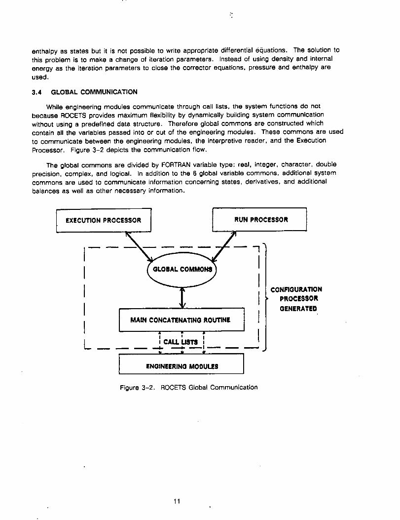
3.4 GLOBAL COMMUNICATION
While engineering modules communicate through call lists, the system functions do notbecause ROCETS provides maximum flexibility by dynamically building system communication
without using a predefined data structure. Therefore global commons are constructed whichcontain all the variables passed into or out of the engineering modules. These commons are usedto communicate between the engineering modules, the interpretive reader, and the Execution
Processor. Figure 3-2 depicts the communication flow.
The global commons are divided by FORTRAN variable type: real, integer, character, double
precision, complex, and logical. In addition to the 6 global variable commons, additional systemcommons are used to communicate information concerning states, derivatives, and additionalbalances as well as other necessary information.
[,x,o+o.,.oc,.,o.i I RUN PROCESSOR
ILI
I/
GLOBAL COMMON_
MAIN CONCATENATING ROUTINE
I II CALL US'I3
ENGINEERING MODULES
CONFIGURATION
PROCESSOR
OENERATEO
Figure 3-2. ROCETS Global Communication
11
3.5 CONFIGURATION PROCESSOR
The goal when defining a simulation is to converts an abstract concept into a mathematical
representation in a flexible, reliable, and convenient manner. Therefore it is desirable to automate
the simulation creation to the extent possible, freeing the user from the tedious aspect of
assembling a simulation. In ROCETS, a Configuration Processor is used to automatically create a
simulation. (Figure 3-1).
The configuration input consists of user commands defining a particular s!mulation in a simple,
structured high-level format. The user defines the system to be modeled in the configuration input
file by specifying component types, design characteristics, the relationship between various
elements of the system, property packages to be used and what properties are to obtained, and
definition of algebraic balances. (Note that algebraic balances can also be defined at run time).
The processor performs two functions in generating a simulation: first it reads the
configuration input, then it reads the interface definitions for the modules specified in the
configuration. The processor needs the engineering module interfaces to determine the required
variables, call lists, variable status (input, output, state, derivative, etc.) and variable type (real,
integer, array, character, etc.). The processor cross references the configuration input and the
module interface information to generate the specific variable names. These names are used to
generate the appropriate call lists for the FORTRAN main program/module communication. This
methodology is what allows the engineering modules to remain separate from the system code.
The global commons are dynamically built for individual simulations during configuration. The
commons consist of the variable names created from the module call lists along with required
system variables.
3.6 RUN PROCESSOR
Run input consists of user commands to execute a configured simulation (Figure 3-1). The
user input contains information required to define schedules, set inputs, define algebraic loops,
specify output, and control execution. The input is in a high-level structured language.
The ability to define and use schedules is quite powerful. Besides allowing schedules for time
inputs, schedules can be set-up to define desired functional relationships in conjunctioz_ with
algebraic loops. As an example, schedules can be defined to set a requested chamber pressure
and mixture ratio and algebraic balances defined to vary valve areas until the requested values are
obtained.
Integration options can be tailored through run input to optimize model operation. The
integration method, perturbation sizes, tolerance, convergence criteria, and activation can be set.
The inputs are divided into "defaults" and "exceptions". It is generally easier to set-up default
information which is adequate for most states and then to override the defaults for specific states
when necessary. Currently the system includes Euler, trapezoidal, first order Gear, and second
order Gear integration schemes. However, other integration schemes can be easily added.
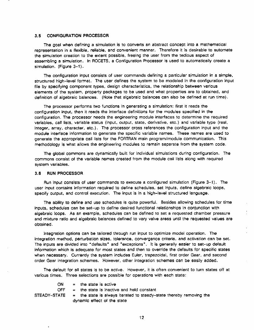
The default for all states is to be active. However, it is often convenient to turn states off at
various times. Three selections are possible for operations with each state:
ON
OFF
STEADY-STATE
= the state is active
= the state is inactive and held constant
= the state is always iterated to steady-state thereby removing the
dynamic effect of the state
12
ROCETSprovidesthe capabilityto definealgebraicbalancesat run time. An independentvariablecan be varied until a dependent variable is equal to another dependent variable or until a
dependent variable is equal to a value. The value may be an input or read from a schedule. This
is especially useful when running operating lines or generating control schedules.
Balance options can be tailored through run input similar to the integration options. The
perturbation sizes, tolerance, convergence criteria, and activation can be set. Like the integration
options, the inputs are divided into "defaults" and "exceptions".
Linearization options can also be defined at run time. included are values to be used for
repeatability and linearity checking. Partials are generated by making a forward perturbation,
backward perturbation, and repeating the forward perturbation. Repeatability is checked by
comparing variable values on the two forward perturbation passes. If the percentage difference is
more than the specified value a warning message will be written. Linearity is checked by
comparing the forward and backward difference partials. If the percentage difference is more than
the specified amount a warning message will be written. In addition to the check values,
parameter names for linear model inputs and outputs are specified by the user.
Linearization defaults are defined to establish the perturbation size for generating partials and
exceptions to the defaults may also be specified. These functions are similar to default and
exception declarations for states and balances.
Simulation output options are handled through the Run Processor. This includes optional print
during Jacobian evaluations and convergence attempts, options for debug output, and specifying
simulation output.
Three run modes are supported: Steady state, Transient, and Linearize. For steady-state,
the number of consecutive steady-state points to be run is also specified. A system parameter
POINT is available for reading schedules with the steady-state point number. This is useful for
running steady-state operating lines or generating control schedules. For a transient, the time
increment, print time, plot time, and termination time are specified. Time is available for reading
schedules. The linearization mode perturbs each state and specified input to generate
state-space model partial derivative matrices.
3.7 MULTI-VARIABLE NEWTON-RAPHSON SOLVER
ROCETS employs a state-of-the-art non-linear equation solver which is the heart of efficient
system operation. It is a modified multi-variable Newton-Rahpson technique, which has been
optimized to operate effectively with the large systems of equations encountered in the rocket
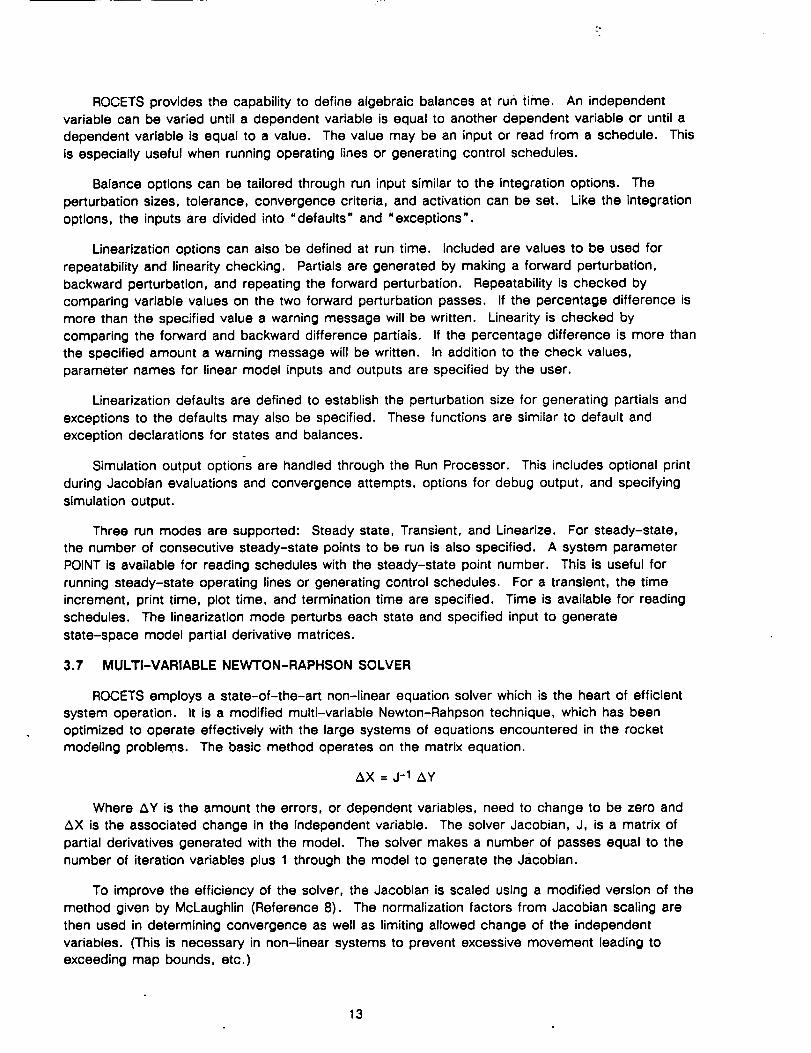
modeling problems. The basic method operates on the matrix equation,
AX = j-1 Ay
Where _Y is the amount the errors, or dependent variables, need to change to be zero and
AX is the associated change in the independent variable. The solver Jacobian, J, is a matrix of
partial derivatives generated with the model. The solver makes a number of passes equal to the
number of iteration variables plus 1 through the model to generate the Jacobian.
To improve the efficiency of the solver, the Jacobian is scaled using a modified version of the
method given by McLaughlin (Reference 8). The normalization factors from Jacobian scaling are
then used in determining convergence as well as limiting allowed change of the independent
variables. (This is necessary in non-Unear systems to prevent excessive movement leading to
exceeding map bounds, etc.)
13
Further enhancements include an algorithm following the Broyden method for updating the
inverse Jacobian. Broyden's method updates the inverse Jacobian without evaluating or inverting a
new matrix, providing a large savings in number of total passes through the model. The matrix
update is basically a secant-type method and is performed during convergence attempts.
In steady-state operation the solver is used to drive all state time derivatives to zero while
simultaneously driving algebraic balance error terms to zero (within a specified tolerance).
Transiently, the solver is used to provide simultaneous closed-loop integration of states and closing
of algebraic loops. Closed-loop integration entails iteration on the simulation state variables (or
state iteration variables) until they are equal to calculated values. This technique provides great
flexibility since integration and algebraic balances are handled simultaneously.
3.8 TRANSIENT INTEGRATION METHODS
Rocket engine simulations comprise a set of stiff differential equations that require special
methods for integration. Integral methods are efficient when the model time increment is small
relative to the time constant associated with the state being integrated. However, as the model
time increment is increased, a critical point is reached where convergence failure results. This
limits the maximum time increment that can be used.
An alternate method is to use the differential form of the corrector equations instead of the
integral form, with the error term being formed as the difference between the actual and
calculated derivative. Scaling by the time constant associated with each state isrecommended by
McLaughlin (Reference 8). The differential method improves convergence when the model time
increment is large compared to the state time constant.
The integration routines used on the ROCETS system automatically uses the appropriate form of the
corrector equation. The engineering modules approximate the time constant for each state and use
this information to select the appropriate integration form. Both the integral and differential forms are
incorporated for trapezoidal, first order Gear, and second order Gear corrector equations.
3.9 LINEARIZATION
The ROCETS system was designed to provide accurate linearization about a steady-state or
transient operating point. Linearization provides state-space matrices of partial derivatives which
can be used for subset model generation, transfer function creation, or multi-variable control
analysis.
Generation of accurate partial derivatives is critical to control design, analysis, and
development. However, complications arise with large simulations using real properties and many
dynamics components. These complications are due to changing iteration variables, the necessity
to close algebraic balances, and from discontinuities associated with thermodynamics properties
around the saturation dome.
The ROCETS linearization methodology automatically accommodates any change of iteration
variables for states and automatically closes all active algebraic balances. With the assumption of
small perturbations such that the partials represent a linear model, the algebraic balances and
state iteration parameters can be solved from a linear set of equations after all partials have been
generated.
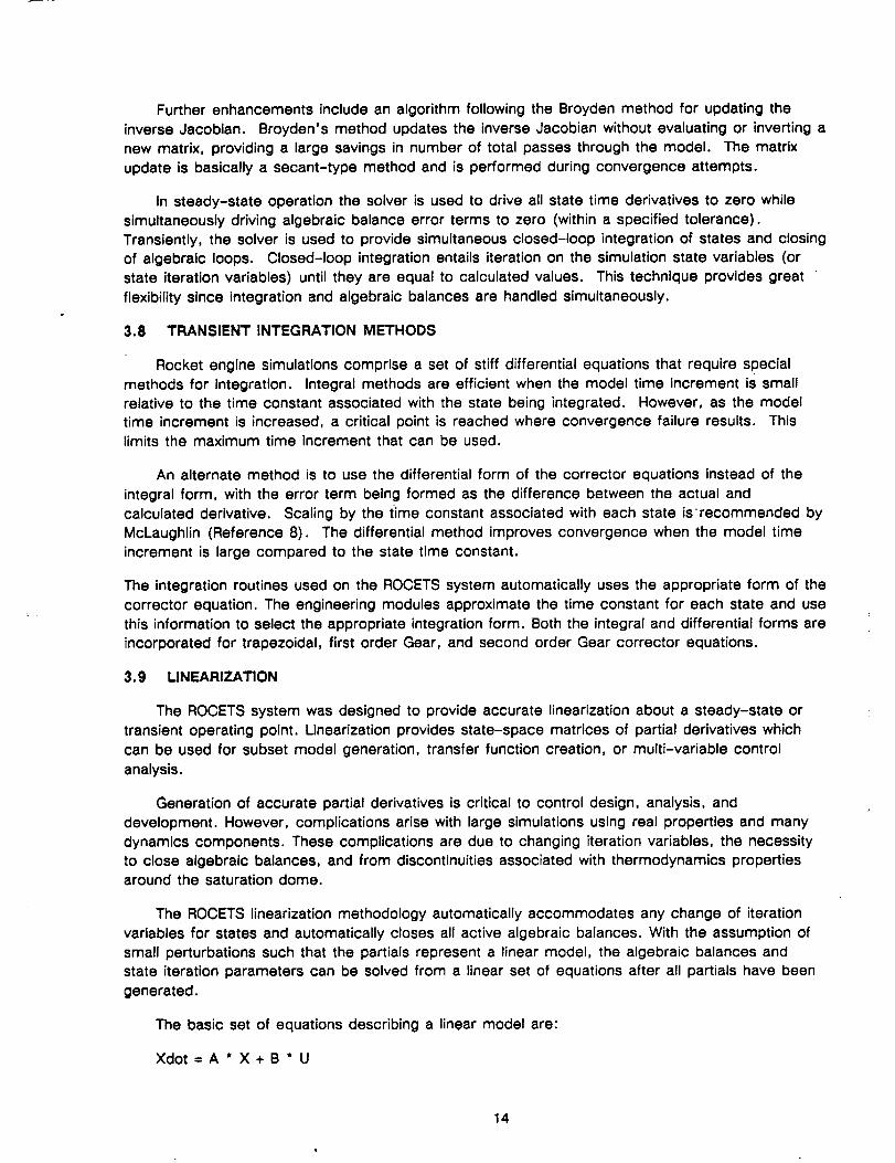
The basic set of equations describing a linear model are:
Xdot = A * X + B * U
14
-°
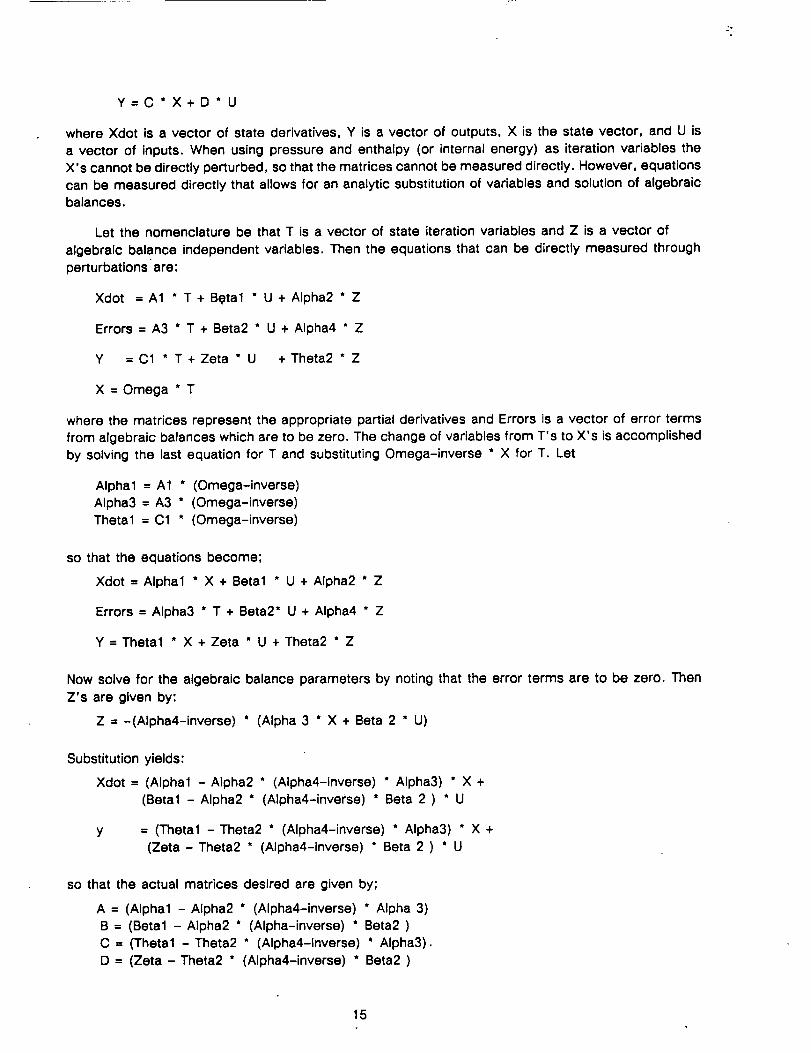
Y=C*X+D*U
where Xdot is a vector of state derivatives, Y is a vector of outputs, X is the state vector, and U is
a vector of inputs. When using pressure and enthalpy (or internal energy) as iteration variables the
X's cannot be directly perturbed, so that the matrices cannot be measured directly. However, equations
can be measured directly that allows for an analytic substitution of variables and solution of algebraic
balances.
Let the nomenclature be that T is a vector of state iteration variables and Z is a vector of
algebraic balance independent variables. Then the equations that can be directly measured through
perturbations are:
Xdot = A1 * T+ BQtal * U + Alpha2 * Z
Errors = A3 * T + Beta2 * U + Alpha4 " Z
Y = C1 * T + Zeta * U +Theta2 * Z
X = Omega * T
where the matrices represent the appropriate partial derivatives and Errors is a vector of error terms
from algebraic balances which are to be zero. The change of variables from T's to X's is accomplished
by solving the last equation for T and substituting Omega-inverse * X for T. Let
Alpha1 = A1 * (Omega-inverse)
Alpha3 = A3 * (Omega-inverse)
Thetal = C1 * (Omega-inverse)
so that the equations become;
Xdot = Alpha1 * X + Beta1 * U + Alpha2 * Z
Errors = Alpha3 * T + Beta2* U + Alpha4 * Z
Y = Thetal * X + Zeta * U + Theta2 * Z
Now solve for the algebraic balance parameters by noting that the error terms are to be zero. Then
Z's are given by:
Z = -(Alpha4-1nverse) * (Alpha 3 * X + Beta 2 * U)
Substitution yields:
Xdot = (Alpha1 - Alpha2 * (Alpha4-inverse) * Alpha3) * X +
(Beta1 - Alpha2 * (Alpha4-inverse) * Beta 2 ) * U
y = (Thetal -Theta2 * (Alpha4-inverse) * Alpha3) * X +
(Zeta - Theta2 * (Alpha4-inverse) * Beta 2 ) * U
so that the actual matrices desired are given by;
A = (Alpha1 - Alpha2 * (Alpha4-inverse) * Alpha 3)
B = (Beta1 - Alpha2 * (Alpha-inverse) * Beta2 )
C = (Thetal - Theta2 * (Alpha4-inverse) * Alpha3).
D = (Zeta - Theta2 * (Alpha4-inverse) * Beta2 )
15
In actual practice, an extremely accurate matrix inversion routine is necessary to preserve the
integrity of the partials. A standard Gauss-Jordan reduction does not have sufficient accuracy.
Therefore a Gauss-Jordan reduction has been combined with a recursion formula to obtain
extremely accurate inversion and all matrix operations are performed in double precision.
3.10 RUN TIME ERROR CHECKING
Run-time error checking is provided to warn of possible invalid model conditions and run-time
errors can also be used as a transient termination criteria. When curves are read with
out-of-range inputs, when internal iterations fail, or any other condition that results in invalid
conditions, the user is informed by appropriate messages in a =debug" file and a numerical status
indicator (N.SI) is set.
Each error location is identified by two eight-character names called "module name" and
"module location". The numerical status indicator is sent to a specific value depending on the
error severity. Through run-time input, the user can control the NSI at which print will be provided
and the NSI which is considered fatal. In addition to the NSI for fatal errors, the user supplies the
number of occurrences of each fatal error before execution terminates.
A list of error codes and their corresponding errors follows:
0000 No error
1000 - 2999 Map Extrapolation
3000 - 4999 Input out of Range
5000 - 6999 Internal Iteration Failure
7000 - 9999 Invalid Solution
10000 Invalid Option (No Default),
execution halted immediately by ERCK00
3.11 DOCUMENTATION
ROCETS documentation starts in the module source code where the system standards require
in the comments cards: A list of all module inputs & outputs with their definitions & units, an
engineering description of the module, a list of sub-modules needed, and a history including
qualification, author, and revision dates. The next level of documentation is contained in the
ROCETS System Design Specification (SDS) of Ref. 4 which contains:
3.12
Section 3.4 Documentation
3.4.1 Standards
3.4.2 Engineering Manual
3.4.3 Programmer's Manual3.4.4 User's Manual
3.4.5 Qualification Test Plans
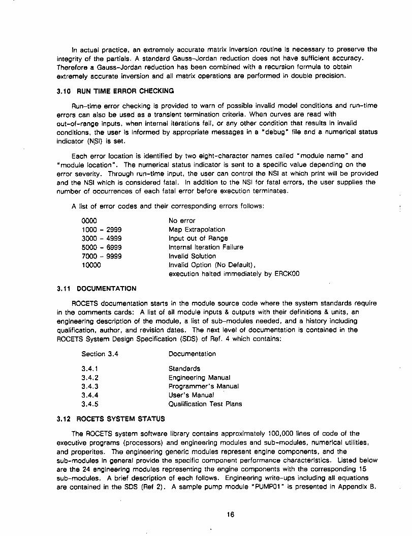
ROCETS SYSTEM STATUS
The ROCETS system software library contains approximately 100,000 lines of code of the
executive programs (processors) and engineering modules and sub-modules, numerical utilities,
and properites. The engineering generic modules represent engine components, and the
sub-modules in general provide the specific component performance characteristics. Listed below
are the 24 engineering modules representing the engine components with the corresponding 15
sub-modules. A brief description of each follows. Engineering write-ups including all equations
are contained in the SDS (Ref 2). A sample pump module "PUMP01" is presented in Appendix B.
16
¢D_.E¢.tg.EE._
PUMP
TURBINE
TURBOPUMP
PREBURNER
MAIN CHAMBER
NOZZLE
IVlODULE
PUMP01
TURB01
TURB02
ROTR00
ROTR01
PBRN01
MCHB01
QCHM01
NOZL00
NCLV00
QNOZ01
PMAP04
PMAP05
PMAP06
PMAP07
PMAP08
TBMP03
TBMP04
TBMP05
TBMP06
CDNZ00
17
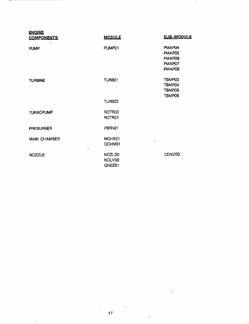
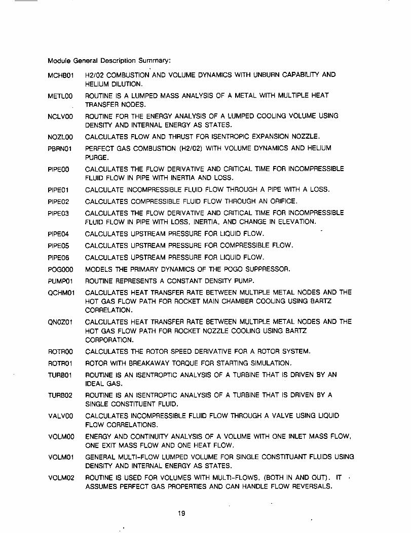
ENGINE(_OMPQNENTS
PLUMBING
MODULE
PIPE00PIPE01PIPE02
PIPE03PIPE04PIPE05
PIPE06
VOLM00
VOLM01VOLM02
SUB-MODULE
FLPM02
PRFP04PRFP06PRFP07
VALVES
POGO SUPPRESSOR
GENERALHEAT TRANSFER
VALV00
POG000
METL00 PRPM01
18
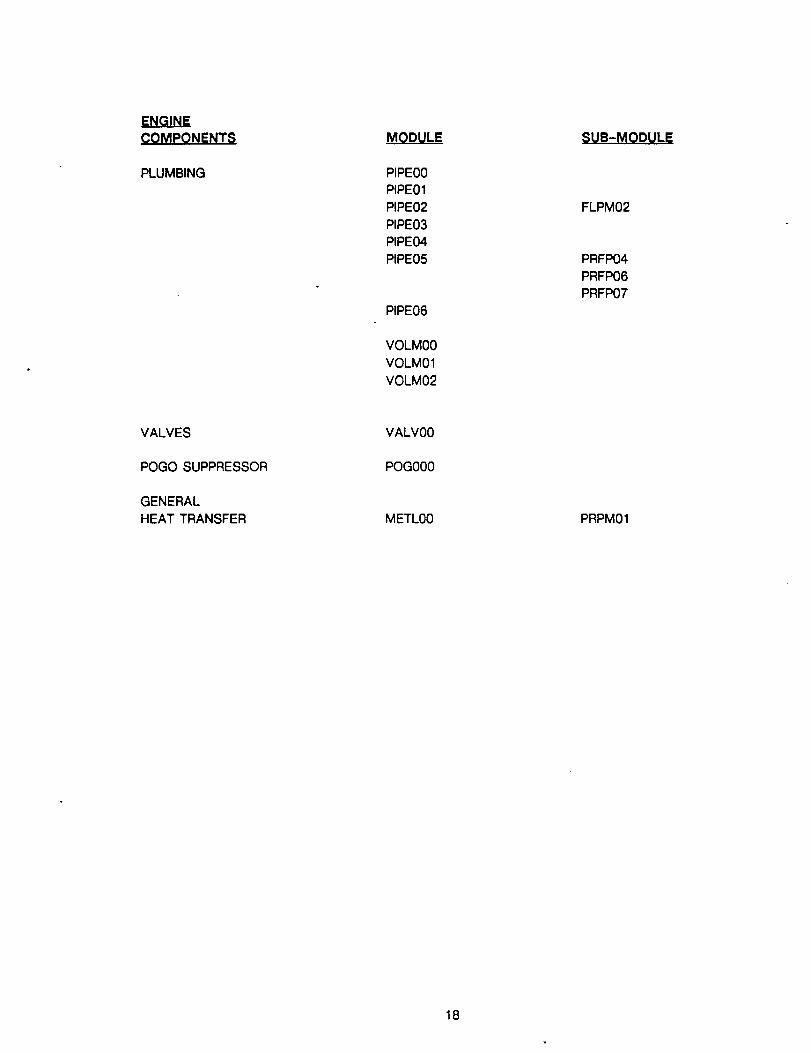
Module General Description Summary:
MCHB01 H2/02 COMBUSTION AND VOLUME DYNAMICS WITH UNBURN CAPABILITY AND
HELIUM DILUTION.
METL00 ROUTINE IS A LUMPED MASS ANALYSIS OF A METAL WITH MULTIPLE HEAT
TRANSFER NODES.
NCLV00 ROUTINE FOR THE ENERGY ANALYSIS OF A LUMPED COOLING VOLUME USING
DENSITY AND INTERNAL ENERGY AS STATES.
NOZL00 CALCULATES FLOW AND THRUST FOR ISENTROPIC EXPANSION NOZZLE.
PBRN01 PERFECT GAS COMBUSTION (H2/02) WITH VOLUME DYNAMICS AND HELIUM
PURGE.
PIPE00 CALCULATES THE FLOW DERIVATIVE AND CRITICAL TIME FOR INCOMPRESSIBLE
FLUID FLOW IN PIPE WITH INERTIA AND LOSS.
PIPE01 CALCULATE INCOMPRESSIBLE FLUID FLOW THROUGH A PIPE WITH A LOSS.
PIPE02 CALCULATES COMPRESSIBLE FLUID FLOW THROUGH AN ORIFICE.
PIPE03 CALCULATES THE FLOW DERIVATIVE AND CRITICAL TIME FOR INCOMPRESSIBLE
FLUID FLOW IN PIPE WITH LOSS, INERTIA, AND CHANGE IN ELEVATION.
PIPE04 CALCULATES UPSTREAM PRESSURE FOR LIQUID FLOW.
PIPE05 CALCULATES UPSTREAM PRESSURE FOR COMPRESSIBLE FLOW.
PIPE06 CALCULATES UPSTREAM PRESSURE FOR LIQUID FLOW.
POG000 MODELS THE PRIMARY DYNAMICS OF THE POGO SUPPRESSOR.
PUMP01 ROUTINE REPRESENTS A CONSTANT DENSITY PUMP.
QCHM01 CALCULATES HEAT TRANSFER RATE BETWEEN MULTIPLE METAL NODES AND THE
HOT GAS FLOW PATH FOR ROCKET MAIN CHAMBER COOLING USING BARTZ
CORRELATION.
QN0Z01 CALCULATES HEAT TRANSFER RATE BETWEEN MULTIPLE METAL NODES AND THE
HOT GAS FLOW PATH FOR ROCKET NOZZLE COOLING USING BARTZ
CORPORATION.
ROTR00 CALCULATES THE ROTOR SPEED DERIVATIVE FOR A ROTOR SYSTEM.
ROTR01 ROTOR WITH BREAKAWAY TORQUE FOR STARTING SIMULATION.
TURB01 ROUTINE IS AN ISENTROPTIC ANALYSIS OF A TURBINE THAT IS DRIVEN BY AN
IDEAL GAS.
TURB02 ROUTINE IS AN ISENTROPTIC ANALYSIS OF A TURBINE THAT IS DRIVEN BY A
SINGLE CONSTITUENT FLUID.
VALV00 CALCULATES INCOMPRESSIBLE FLUID FLOW THROUGH A VALVE USING LIQUID
FLOW CORRELATIONS.
VOLM00 ENERGY AND CONTINUITY ANALYSIS OF A VOLUME WITH ONE INLET MASS FLOW,
ONE EXIT MASS FLOW AND ONE HEAT FLOW.
VOLM01 GENERAL MULTI-FLOW LUMPED VOLUME FOR SINGLE CONSTITUANT FLUIDS USING
DENSITY AND INTERNAL ENERGY AS STATES.
VOLM02 ROUTINE IS USED FOR VOLUMES WITH MULTI-FLOWS, (BOTH IN AND OUT). IT
ASSUMES PERFECT GAS PROPERTIES AND CAN HANDLE FLOW REVERSALS.
19
CDNZ00
FLPM02
MACH03
MACHO4
PMAP04
PMAP05
PMAP06
PAMP07
PMAP08
PRFP04
PRFP06
PRFP07
TBMP03
TBMP04
TBMP05
TBMP06
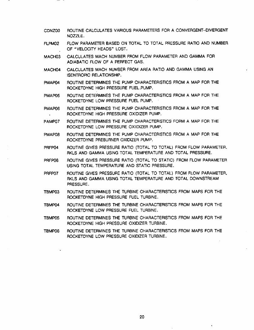
ROUTINE CALCULATES VARIOUS PARAMETERS FOR A CONVERGENT-DIVERGENT
NOZZLE.
FLOW PARAMETER BASED ON TOTAL TO TOTAL PRESSURE RATIO AND NUMBER
OF "VELOCITY HEADS" LOST.
CALCULATES MACH NUMBER FROM FLOW PARAMETER AND GAMMA FOR
ADIABATIC FLOW OF A PERFECT GAS.
CALCULATES MACH NUMBER FROM AREA RATIO AND GAMMA USING AN
ISENTROPIC RELATIONSHIP.
ROUTINE DETERMINES THE PUMP CHARACTERISTICS FROM A MAP FOR THE
ROCKETDYNE HIGH PRESSURE FUEL.PUMP.
ROUTINE DETERMINES THE PUMP CHARACTERISTICS FROM A MAP FOR THE
ROCKETDYNE LOW PRESSURE FUEL PUMP.
ROUTINE DETERMINES THE PUMP CHARACTERISTICS FROM A MAP FOR THE
ROCKETDYNE HIGH PRESSURE OXIDIZER PUMP.
ROUTINE DETERMINES THE PUMP CHARACTERISTICS FORM A MAP FOR THE
ROCKETDYNE LOW PRESSURE OXIIDIZER PUMP.
ROUTINE DETERMINES THE PUMP CHARACTERISTICS FROM A MAP FOR THE
ROCKETDYNE PREBURNER OXIDIZER PUMP.
ROUTINE GIVES PRESSURE RATIO (TOTAL TO TOTAL) FROM FLOW PARAMETER,
RKLS AND GAMMA USING TOTAL TEMPERATURE AND TOTAL PRESSURE.
ROUTINE GIVES PRESSURE RATIO (TOTAL TO STATIC) FROM FLOW PARAMETER
USING TOTAL TEMPERATURE AND STATIC PRESSURE.
ROUTINE GIVES PRESSURE RATIO (TOTAL TO TOTAL) FROM FLOW PARAMETER,
RKLS AND GAMMA USING TOTAL TEMPERATURE AND TOTAL DOWNSTREAM
PRESSURE.
ROUTINE DETERMINES THE TURBINE CHARACTERISTICS FROM MAPS FOR THE
ROCKETDYNE HIGH PRESSURE FUEL TURBINE.
ROUTINE DETERMINES THE TURBINE CHARACTERISTICS FROM MAPS FOR THE
ROCKETDYNE LOW PRESSURE FUEL TURBINE.
ROUTINE DETERMINES THE TURBINE CHARACTERISTICS FROM MAPS FOR THE
ROCKETDYNE HIGH PRESSURE OXIDIZER TURBINE.
ROUTINE DETERMINES THE TURBINE CHARACTERISTICS FROM MAPS FOR THE
ROCKETDYNE LOW PRESSURE OXIDIZER TURBINE.
2O
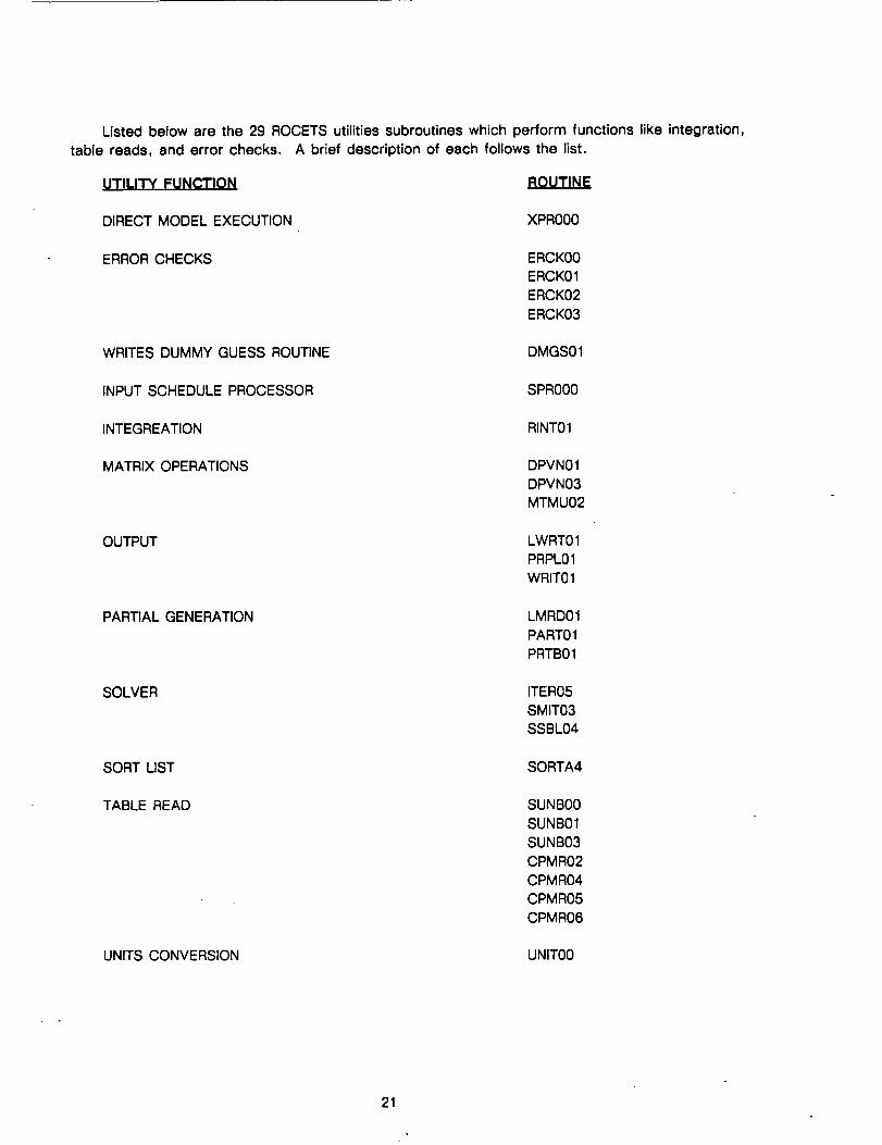
Listedbeloware the 29ROCETSutilitiessubroutineswhichperformfunctionslikeintegration,table reads,and error checks. A brief descriptionof eachfollowsthe list.
UTILITY FUNCTION ROUTINE
DIRECT MODEL EXECUTION XPR000
ERROR CHECKS ERCK00
ERCK01
ERCK02
ERCK03
WRITES DUMMY GUESS ROUTINE DMGS01
INPUT SCHEDULE PROCESSOR SPR000
INTEGREATION RINT01
MATRIX OPERATIONS
OUTPUT
DPVN01
DPVN03
MTMU02
LWRT01
PRPL01
WRIT01
PARTIAL GENERATION LMRD01
PART01
PRTB01
SOLVER ITER05
SMIT03
SSBL04
SORT LIST SORTA4
TABLE READ SUNB00
SUNB01
SUNB03
CPMR02
CPMR04
CPMR05
CPMR06
UNITS CONVERSION UNIT00
21
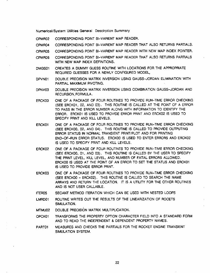
Numerical/System Utilities General
CPMR02
CPMR04
CPMR05
CPMR06
DMGS01
DPVN01
DPNV03
ERCK00
ERCK01
ERCK02
ERCK03
ITER05
LMRD01
MTMU02
OPCK01
PART01
Descirption Summary
CORRESPONDING POINT BI-VARIENT MAP READER.
CORRESPONDING POINT BI-VARIENT MAP READER THAT ALSO RETURNS PARTIALS.
CORRESPONDING POINT BI-VARIENT MAP READER WITH NEW MAP INDEX POINTER.
CORRESPONDING POINT BI-VARIENT MAP READER THAT ALSO RETURNS PARTIALS
WITH NEW MAP INDEX DEFINITIONS.
CREATES A DUMMY GUESS ROUTINE WITH LOCATIONS FOR THE APPROPRIATE
REQUIRED GUESSES FOR A NEWLY CONFIGURED MODEL,
DOUBLE PRECISION MATRIX INVERSION USING GAUSS-JORDAN ELIMINATION WITH
PARTIAL MAXIMUM PIVOTING.
DOUBLE PRECISION MATRIX INVERSION USING COMBINATION GAUSS-JORDAN AND
RECURSION. FORMULA.
ONE OF A PACKAGE OF FOUR ROUTINES TO PROVIDE RUN-TIME ERROR CHECKING
(SEE ERCK01, 02, AND 03). THIS ROUTINE IS CALLED AT THE POINT OF A ERROR
TO PASS IN THE ERROR NUMBER ALONG WITH INFORMATION TO IDENTIFY THE
ERROR. ERCK01 IS USED TO PROVIDE ERROR PRINT AND ERCK02 IS USED TO
SPECIFY PRINT AND KILL LEVELS.
ONE OF A PACKAGE OF FOUR ROUTINES TO PROVIDE RUN-TIME ERROR CHECKING
(SEE ERCK00, 02, AND 04). THIS ROUTINE IS CALLED TO PROVIDE OUTPUTING
ERROR STATUS IN NORMAL TRANSIENT PRINT/PLOT AND FOR PRINTING
END-OF-RUN ERROR STATUS. ERCK00 IS USED TO ENTER ERRORS AND ERCK02
IS USED TO SPECIFY PRINT AND KILL LEVELS.
ONE OF A PACKAGE OF FOUR ROUTINES TO PROVIDE RUN-TIME ERROR CHECKING
(SEE ERCK00, 01, AND 03). THIS ROUTINE IS CALLED BY THE USER TO SPECIFY
THE PRINT LEVEL, KILL LEVEL, AND NUMBER OF FATAL ERRORS ALLOWED.
ERCK00 IS USED AT THE POINT OF AN ERROR TO SET THE STATUS AND ERCK01
IS USED TO PROVIDE ERROR PRINT.
ONE OF A PACKAGE OF FOUR ROUTINES TO PROVIDE RUN-TIME ERROR CHECKING
(SEE ERCK00 - ERCK02). THIS ROUTINE IS CALLED TO SEARCH THE NAME
ARRAYS AND RETURN THE LOCATION. IT IS A UTILITY FOR THE OTHER ROUTINES
AND IS NOT USER CALLABLE.
SECANT METHOD ITERATION WHICH CAN BE USED WITH NESTED LOOPS
ROUTINE WRITES OUT THE RESULTS OF THE LINEARIZATION OF ROCETS
SIMULATION.
DOUBLE PRECISI(_N MATRIX MULTIPLICATION.
TRANSFORMS THE PROPERTY OPTION CHARACTER FIELD INTO A STANDARD FORM
AND TO READ THE INDEPENDENT & DEPENDENT PROPERTY NAMES.
MEASURES AND CHECKS THE PARTIALS FOR THE ROCKET ENGINE TRANSIENT
SIMULATION SYSTEM.
22
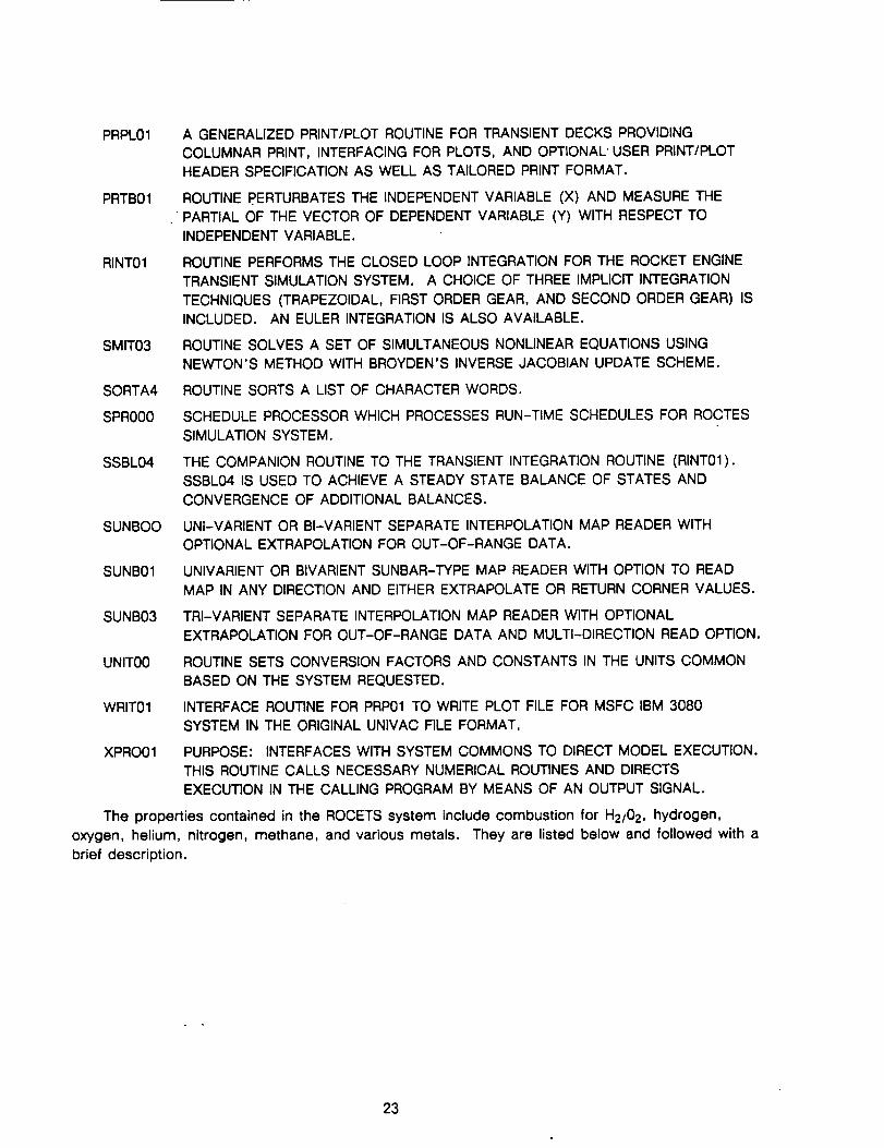
PRPL01 A GENERALIZED PRINT/PLOT ROUTINE FOR TRANSIENT DECKS PROVIDING
COLUMNAR PRINT, INTERFACING FOR PLOTS, AND OPTIONAL" USER PRINT/PLOT
HEADER SPECIFICATION AS WELL AS TAILORED PRINT FORMAT.
PRTB01 ROUTINE PERTURBATES THE INDEPENDENT VARIABLE (X) AND MEASURE THE
PARTIAL OF THE VECTOR OF DEPENDENT VARIABLE (Y) WITH RESPECT TO
INDEPENDENT VARIABLE.
RINT01 ROUTINE PERFORMS THE CLOSED LOOP INTEGRATION FOR THE ROCKET ENGINE
TRANSIENT SIMULATION SYSTEM. A CHOICE OF THREE IMPLICIT INTEGRATION
TECHNIQUES (TRAPEZOIDAL, FIRST ORDER GEAR, AND SECOND ORDER GEAR) IS
INCLUDED. AN EULER INTEGRATION IS ALSO AVAILABLE.
SMIT03 ROUTINE SOLVES A SET OF SIMULTANEOUS NONLINEAR EQUATIONS USING
NEWTON'S METHOD WITH BROYDEN°S INVERSE JACOBIAN UPDATE SCHEME.
SORTA4 ROUTINE SORTS A LIST OF CHARACTER WORDS.
SPR000 SCHEDULE PROCESSOR WHICH PROCESSES RUN-TIME SCHEDULES FOR ROCTES
SIMULATION SYSTEM.
SSBL04 THE COMPANION ROUTINE TO THE TRANSIENT INTEGRATION ROUTINE (RINT01).
SSBL04 IS USED TO ACHIEVE A STEADY STATE BALANCE OF STATES AND
CONVERGENCE OF ADDITIONAL BALANCES.
SUNBOO UNI-VARIENT OR BI-VARIENT SEPARATE INTERPOLATION MAP READER WITH
OPTIONAL EXTRAPOLATION FOR OUT-OF-RANGE DATA.
SUNB01 UNIVARIENT OR BIVARIENT SUNBAR-TYPE MAP READER WITH OPTION TO READ
MAP IN ANY DIRECTION AND EITHER EXTRAPOLATE OR RETURN CORNER VALUES.
SUNB03 TRI-VARIENT SEPARATE INTERPOLATION MAP READER WITH OPTIONAL
EXTRAPOLATION FOR OUT-OF-RANGE DATA AND MULTI-DIRECTION READ OPTION.
UNIT00 ROUTINE SETS CONVERSION FACTORS AND CONSTANTS IN THE UNITS COMMON
BASED ON THE SYSTEM REQUESTED.
WRIT01 INTERFACE ROUTINE FOR PRP01 TO WRITE PLOT FILE FOR MSFC IBM 3080
SYSTEM IN THE ORIGINAL UNIVAC FILE FORMAT.
XPRO01 PURPOSE: INTERFACES WITH SYSTEM COMMONS TO DIRECT MODEL EXECUTION.
THIS ROUTINE CALLS NECESSARY NUMERICAL ROUTINES AND DIRECTS
EXECUTION IN THE CALLING PROGRAM BY MEANS OF AN OUTPUT SIGNAL.
The properties contained in the ROCETS system include combustion for H2/02, hydrogen,
oxygen, helium, nitrogen, methane, and various metals. They are listed below and followed with a
brief description.
23
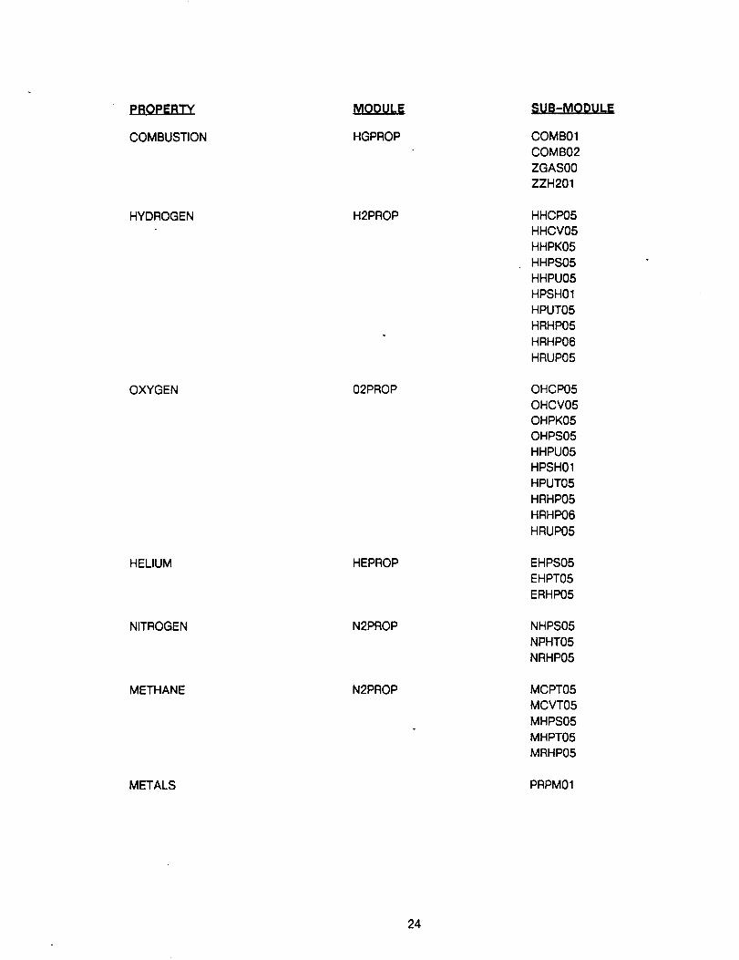
PROPERTY
COMBUSTION
HYDROGEN
OXYGEN
HELIUM
NITROGEN
METHANE
METALS
MODULE
HGPROP
H2PROP
02PROP
HEPROP
N2PROP
N2PROP
-._La=M.O..EU.EE
COMB01
COMB02
ZGAS00
ZZH201
HHCP05
HHCV05
HHPK05
HHPS05
HHPU05
HPSH01
HPUT05
HRHP05
HRHP06
HRUP05
OHCP05
OHCV05
OHPK05
OHPS05
HHPU05
HPSH01
HPUT05
HRHP05
HRHP06
HRUP05
EHPS05
EHPT05
ERHP05
NHPS05
NPHT05
NRHP05
MCPT05
MCVT05
MHPS05
MHPT05
MRHP05
PRPM01
24
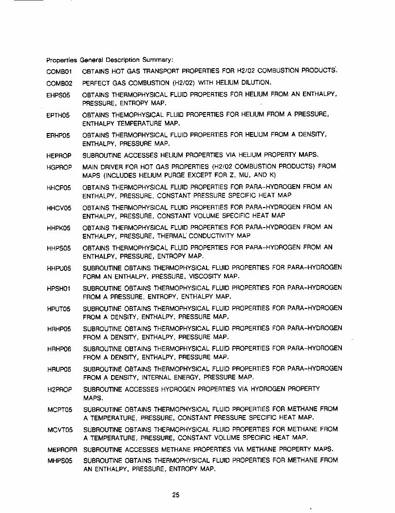
PropertiesGeneralDescription Summary:
COMB01 OBTAINS HOT GAS TRANSPORT PROPERTIES FOR H2/02 COMBUSTION PRODUCTS.
COMB02 PERFECT GAS COMBUSTION (H2/02) WITH HELIUM DILUTION.
EHPS05 OBTAINS THERMOPHYSICAL FLUID PROPERTIES FOR HELIUM FROM AN ENTHALPY,
PRESSURE, ENTROPY MAP.
EPTH05 OBTAINS THEMOPHYSICAL FLUID PROPERTIES FOR HELIUM FROM A PRESSURE,
ENTHALPY TEMPERATURE MAP.
ERHP05 OBTAINS THERMOPHYSICAL FLUID PROPERTIES FOR HELIUM FROM A DENSITY,
ENTHALPY, PRESSURE MAP.
HEPROP SUBROUTINE ACCESSES HELIUM PROPERTIES VIA HELIUM PROPERTY MAPS.
HGPROP MAIN DRIVER FOR HOT GAS PROPERTIES (H2/02 COMBUSTION PRODUCTS) FROM
MAPS (INCLUDES HELIUM PURGE EXCEPT FOR Z, MU, AND K)
HHCP05 OBTAINS THERMOPHYSICAL FLUID PROPERTIES FOR PARA-HYDROGEN FROM AN
ENTHALPY, PRESSURE, CONSTANT PRESSURE SPECIFIC HEAT MAP
HHCV05 OBTAINS THERMOPHYSICAL FLUID PROPERTIES FOR PARA-HYDROGEN FROM AN
ENTHALPY, PRESSURE, CONSTANT VOLUME SPECIFIC HEAT MAP
HHPK05 OBTAINS THERMOPHYSICAL FLUID PROPERTIES FOR PARA-HYDROGEN FROM AN
ENTHALPY, PRESSURE, THERMAL CONDUCTIVITY MAP
HHPS05 OBTAINS THERMOPHYSICAL FLUID PROPERTIES FOR PARA-HYDROGEN FROM AN
ENTHALPY, PRESSURE, ENTROPY MAP.
HHPU05 SUBROUTINE OBTAINS THERMOPHYSICAL FLUID PROPERTIES FOR PARA-HYDROGEN
FORM AN ENTHALPY, PRESSURE, VISCOSITY MAP.
HPSH01 SUBROUTINE OBTAINS THERMOPHYSICAL FLUID PROPERTIES FOR PARA-HYDROGEN
FROM A PRESSURE, ENTROPY, ENTHALPY MAP.
HPUT05 SUBROUTINE OBTAINS THERMOPHYSlCAL FLUID PROPERTIES FOR PARA-HYDROGEN
HRHP05
HRHP06
HRUP05
H2PROP
MCPT05
MCVT05
MEPROPR
MHPS05
FROM A DENSITY, ENTHALPY, PRESSURE MAP.
SUBROUTINE OBTAINS THERMOPHYSICAL FLUID
FROM A DENSITY, ENTHALPY, PRESSURE MAP.
SUBROUTINE OBTAINS THERMOPHYSICAL FLUID
FROM A DENSITY, ENTHALPY, PRESSURE MAP.
PROPERTIES FOR PARA-HYDROGEN
PROPERTIES FOR PARA-HYDROGEN
SUBROUTINE OBTAINS THERMOPHYSICAL FLUID PROPERTIES FOR PARA-HYDROGEN
FROM A DENSITY, INTERNAL ENERGY, PRESSURE MAP.
SUBROUTINE ACCESSES HYDROGEN PROPERTIES VIA HYDROGEN PROPERTY
MAPS.
SUBROUTINE OBTAINS THERMOPHYSICAL FLUID PROPERTIES FOR METHANE FROM
A TEMPERATURE, PRESSURE, CONSTANT PRESSURE SPECIFIC HEAT MAP.
SUBROUTINE OBTAINS THERMOPHYSICAL FLUID PROPERTIES FOR METHANE FROM
A TEMPERATURE, PRESSURE, CONSTANT VOLUME SPECIFIC HEAT MAP.
SUBROUTINE ACCESSES METHANE PROPERTIES VIA METHANE PROPERTY MAPS.
SUBROUTINE OBTAINS THERMOPHYSlCAL FLUID PROPERTIES FOR METHANE FROM
AN ENTHALPY, PRESSURE, ENTROPY MAP.
25
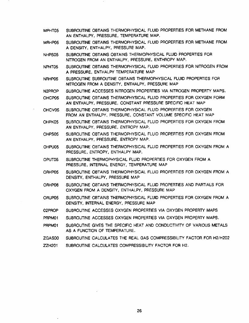
MPHT05
MRHP05
NHPS05
NPHT05
NRHP05
N2PROP
OHCP05
OHCV05
OHPK05
OHPS05
OHPU05
OPUT05
ORHP05
ORHP06
ORUP05
02PROP
PRPM01
PRPM01
ZGAS00
ZZH201
SUBROUTINE OBTAINS THERMOPHYSICAL FLUID PROPERTIES FOR METHANE FROM
AN ENTHALPY, PRESSURE, TEMPERATURE MAP.
SUBROUTINE OBTAINS THERMOPHYSICAL FLUID PROPERTIES FOR METHANE FROM
A DENSITY, ENTHALPY, PRESSURE MAP.
SUBROUTINE OBTAINS OBTAINS THERMOPHYSICAL FLUID PROPERTIES FOR
NITROGEN FROM AN ENTHALPY, PRESSURE, ENTHROPY MAP.
SUBROUTINE OBTAINS THERMOPHYSICAL FLUID PROPERTIES FOR NITROGEN FROM
A PRESSURE, ENTHALPY TEMPERATURE MAP
SUBROUTINE SUBROUTINE OBTAINS THERMOPHYSICAL FLUID PROPERTIES FOR
NITROGEN FROM A DENSITY, ENTHALPY, PRESSURE MAP
SUBROUTINE ACCESSES NITROGEN PROPERTIES VIA NITROGEN PROPERTY MAPS.
SUBROUTINE OBTAINS THERMOPHYSICAL FLUID PROPERTIES FOR OXYGEN FORM
AN ENTHALPY, PRESSURE, CONSTANT PRESSURE SPECIFIC HEAT MAP
SUBROUTINE OBTAINS THERMOPHYSICAL FLUID PROPERTIES FOR OXYGEN
FROM AN ENTHALPY, PRESSURE, CONSTANT VOLUME SPECIFIC HEAT MAP
SUBROUTINE OBTAINS THERMOPHYSICAL FLUID PROPERTIES FOR OXYGEN FROM
AN ENTHALPY, PRESSURE, ENTROPY MAP.
SUBROUTINE OBTAINS THERMOPHYSICAL FLUID PROPERTIES FOR OXYGEN FROM
AN ENTHALPY, PRESSURE, ENTROPY MAP.
SUBROUTINE OBTAINS THERMOPHYSICAL FLUID PROPERTIES FOR OXYGEN FROM A
PRESSURE, ENTROPY, ENTHALPY MAP.
SUBROUTINE THERMOPHYSICAL FLUID PROPERTIES FOR OXYGEN FROM A
PRESSURE, INTERNAL ENERGY, TEMPERATURE MAP
SUBROUTINE OBTAINS THERMOPHYSICAL FLUID PROPERTIES FOR OXYGEN FROM A
DENSITY, ENTHALPY, PRESSURE MAP
SUBROUTINE OBTAINS THERMOPHYSICAL FLUID PROPERTIES AND PARTIALS FOR
OXYGEN FROM A DENSITY, ENTHALPY, PRESSURE MAP
SUBROUTINE OBTAINS THERMOPHYSICAL FLUID PROPERTIES FOR OXYGEN FROM A
DENSITY, INTERNAL ENERGY, PRESSURE MAP
SUBROUTINE ACCESSES OXYGEN PROPERTIES VIA OXYGEN PROPERTY MAPS
SUBROUTINE ACCESSES OXYGEN PROPERTIES VIA OXYGEN PROPERTY MAPS.
SUBROUTINE GIVES THE SPECIFIC HEAT AND CONDUCTIVITY OF VARIOUS METALS
AS A FUNCTION OF TEMPERATURE.
SUBROUTINE CALCULATES THE REAL GAS COMPRESSIBILITY FACTOR FOR H2/H202
SUBROUTINE CALCULATES COMPRESSIBILITY FACTOR FOR H2.
26
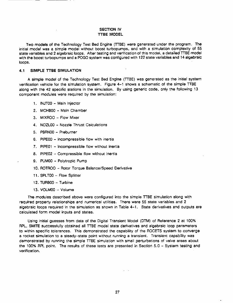
SECTION IV
TTBE MODEL
Two models of the Technology Test Bed Engine ('I-rBE) were generated under the program. The
initial model was a simple model without boost turbopumps, and with a simulation complexity of 55state variables and 2 algebraic loops. After testing and verification of this model, a detailed TTBE model
with the boost turbopumps and a POGO system was configured with 122 state variables and 14 algebraic
loops.
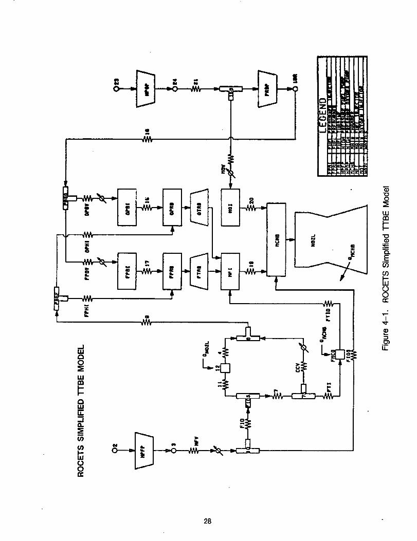
4.1 SIMPLE TTBE SIMULATION
A simple model of the Technology Test Bed Engine (TTBE) was generated as the initial system
verification vehicle for the simulation system. Figure 4-1 shows a schematic of the simple TTBE
along with the 42 specific stations in the simulation. By using generic code, only the following 13
component modules were required by the simulation:
1. INJT00 - Main Injector
2. MCHB00 - Main Chamber
3. MIXROO - Flow Mixer
4. NOZL00 - Nozzle Thrust Calculations
5. PBRN00 - Preburner
6. PIPE00 - Incompressible flow with inertia
7. PIPE01 - Incompressible flow without inertia
8. PIPE02 - Compressible flow without inertia
9. PUM00 - Polytropic Pump
10. ROTROO - Rotor Torque Balance/Speed Derivative
11. SPLT00 - Flow Splitter
12. TURB00 - Turbine
13. VOLM00 - Volume
The modules described above were configured into the simple TTBE simulation along with
required property relationships and numerical utilities. There were 55 state variables and 2
algebraic loops required in the simulation as shown in Table 4-1. State derivatives and outputs are
calculated form model inputs and states.
Using initial guesses from data of the Digital Transient Model (DTM) of Reference 2 at 100%
RPL, SMITE successfully obtained all TTBE model state derivatives and algebraic loop parameters
to within specific tolerances. This demonstrated the capability of the ROCETS system to converge
a rocket simulation to a steady-state point without running a transient. Transient capability was
demonstrated by running the simple RBE simulation with small perturbations of Valve areas about
the 100% RPL point. The results of these tests are presented in Section 5.0 - System testing and
verification.
27
mo131:
i
O
I.LI¢'n
Q.E
BoO
I
u.
28 "
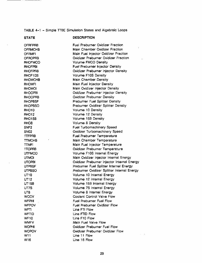
TABLE 4-1 - Simple TTBE Simulation States and Algebraic Loops
STATE DESCRIPTION
OFRFPRB
OFRMCHB
OFRMFI
OFROPRB
RHOFMCO
RHOFPBI
RHOFPRB
RHOF10S
RHOMCHB
RHOMFI
RHOMOI
RHOOPBI
RHOOPRB
RHOPBSF
RHOPBSO
RHO10
RHO12
RHO 15B
RHO8
SNF2
SN02
"I-FFPRB
TTMCHB
TrMFI
TTOPRB
UTFMCO
UTMOI
UTOPBI
UTPBSF
UTPBSO
UT10
UT12
UT15B
UT7S
UT8
WCCV
WFPHI
WFPOV
WFTI
WFTID
WF10
WMFV
WOPHI
WOPOV
Wll
W16
Fuel Preburner Oxidizer Fraction
Main Chamber Oxidizer Fraction
Main Fuel Injector Oxidizer Fraction
Oxidizer Preburner Oxidizer Fraction
Volume FMCO Density
Fuel Preburner Injector Density
Oxidizer Preburner Injector Density
Volume F10S Density
Main Chamber Density
Main Fuel Injector Density
Main Oxidizer Injector Density
Oxidizer Preburner Injector Density
Oxidizer Preburner Density
Preburner Fuel Splitter Density
Preburner Oxidizer Splitter Density
Volume 10 Density
Volume 12 Density
Volume 15B Density
Volume 8 Density
Fuel Turbomachinery Speed
Oxidizer Turbomachinery Speed
Fuel Preburner Temperature
Main Chamber Temperature
Main Fuel Injector Temperature
Oxidizer Preburner Temperature
Volume F10S Internal Energy
Main Oxidizer Injector Internal Energy
Oxidizer Preburner Injector Internal Energy
Preburner Fuel Splitter Internal Energy
Preburner Oxidizer Splitter Internal Energy
Volume 10 Internal Energy
Volume 12 Internal Energy
Volume 15B Internal Energy
Volume 7S Internal Energy
Volume 8 Internal EnergyCoolant Control Valve Flow
Fuel Preburner Fuel Flow
Fuel Preburner Oxidizer Flow
Line FTI Flow
Line FTID Flow
Line F10 Flow
Main Fuel Valve Flow
Oxidizer Preburner Fuel Flow
Oxidizer Preburner Oxidizer Flow
Line 11 Flow
Line 16 Flow
29
W20W21W4W7W9
Line 20 FlowLine 21 FlowLine 4 FlowLine 7 Flow FlowLine 9 Flow
ITERATION VARIABLE DESCRIPTION
WFTRB
WOTRB
Fuel Turbine Flow - Iterated until equal tocalculated value
LOX Turbine flow - Iterated until equal tocalculated value
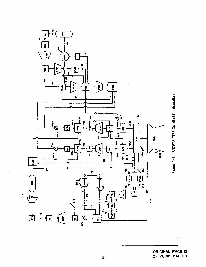
4.2 DETAILED TTBE SIMULATION
After successful verification of the simple TTBE model, a detailed TTBE model simulation was
developed. The approach was to model the Iox side and test, then the fuel side and test, thenthe hot gas system and test, and finally connect the three sub-systems and test. A schematic ofthe entire engine simulation is presented on Figure 4-2. There are 122 states and 14 additionalbalances in the simulation. Each of the station names are labeled on the schematic.
A description of the modules used to configure the TTBE along with a list of the TTBEschematic names that use that particular module follows.
3O
|
Ib
l--
00
1II
IIII:n
III
gI:I:
I
._oii
31
ORIGINAL PAGE IS
OF POOR QUALITY
Pioe Modules
Six pipe modules were used to configure the TTBE. They are PIPEO0, PIPE01, PIPE02, PIPE03,
PIPE05, PIPE06. Following is a list of the TTBE schematic pipe names that use the corresponding
pipe routines, a description of each module, and the states of each module.
M_kLLe._ELEE.Q.Q
Schematic Names:
Descriotion:
F1, F2, F5, F6, F7, F8, FFPB, FOPB, 02, 03, 05
OFPB, OOPB, OINJ
This module calculates the flow derivative for incompressible fluid flow in a pipe with
inertial effects.
Stotes and State Derivatives:
PIPEO0 has flow as a state and calculates the flow derivative.
MI_zcLuJL_EDj_
Schematic Names: F3, F4, Fll, F12, F13, F14, F15, FSLV, FIG, FTC,
OTC, 04, 06, 07, MOV, FPOV, OPOV
Description:
This module calculates flow through a pipe for an incompressible fluid.
States and State Derivatives:
PIPE01 calculates flow but it is not treated as a state. This module does not treat any
parameters as states and therefore does not calculate any state derivatives.
M.o.¢Lu[e_eteE_
$ohematic Names: HG3, HG4, OLK
Description:
This module calculates flow through a pipe for a compressible fluid.
States and State Derivatives:
PIPE02 calculates flow but it is not treated as a state. This module does not treat any a
parameters as states and therefore does not calculate any state derivatives.
Module pIPE03
Schematic Names: 01
Descriotion:
This module calculates the flow derivative for incompressible fluid flow in a pipe with
inertial effects and elevation change.
32
States and State Derivatives:
PIPE03 has flow as a state and calculates the flow derivative.
Schematic Names: HG1, HG2, HG3, HG6, FINJ, HG5
Descrlotion:
This module calculates upstream pressure for compressible flow.
States and State Derivatives:
PIPE05 uses flow but it is not treated as a state. This module does not treat any
parameters as states and therefore does not calculate any state derivatives.
M_LuLe_EtEE_
Schematic Names: F9, F10
Descriotion:
This module calculates upstream pressure for incompressible flow.
States and State Derivatives:
PIPE06 uses flow but it is not treated as a state. This module does not treat any
parameters as states and therefore does not calculate any state derivatives.
Valve Module
One valve module, VALV00, was used to configure the T-I'BE. Following is a list of the TTBE
schematic valve names that use the VALV00 routine, a description of the VALV00 module, and the
states of the VALV00 module.
Mo_lule VALV00
Schematic Names: MFV, CCV
This module calculates flow through VALVE for an incompressible fluid.Q
States and State Derivatives:
VALV00 calculates flow but it is not treated as a state. This module does not treat any a
parameters as states and therefore does not calculate any state derivatives.
33
Volume Module
Schematic; Names:
Descriotion:
VL1, VL2, VL5, VL9, VLIO, VL14, VL15, VL17, VL18, VL22
This module performs a continuity and energy analysis of a volume for pure fluids with
one inlet flow, one exit flow, and one heat flow.
States and State Derivatives:
VOLM00 has density and internal energy as states. Corresponding derivatives are
calculated for each state.
Module VOLM01
Schematic Names: VL3, VL4, VLS, VL13, VL16, VL19, VL20, VL21, PBSF, PBS0
Descriotion:
The module performs a continuity and energy analysis of a volume for pure fluids with
multiple inlet flows, multiple exit flows, and multiple heat flows.
States and State Derivatives:
VOLM01 has density and internal energy as states. Corresponding derivatives are
calculated for each state.
t_Lu_LE._.M02
Schematic Names: FTBP, OTBP, FSF, OSF, MFI
This module performs a continuity and energy analysis of a volume for perfect gases with
oxygen, hydrogen, and helium as possible constituents. The analysis is performed with
multiple inlet flows, multiple exit flows, and multiple heat flows.
States and State Derivatives:
VOLM02 has pressure, temperature, oxidizer fraction, and helium fraction as states.
Corresponding derivatives are calculated for each state.
34
Schematic NAMES: VL6, VL7, VL11, VL12
This module models the cooling of the chamber and nozzle. The module performs a
continuity and heat transfer analysis of a volume of pure fluids with one inlet flow, one
exit flow, multiple node metal temperatures, and multiple node heat transfer surface
areas. The heat transfer rate is calculated for each node.
States and State Derivatives:
NCLVO0 has density and internal energy as states. Corresponding derivatives are
calculated for each state.
Rotor Module
The inertial and transient speed effects for turbopumps are modeled by the ROTR00
module which mechanically links each turbopump together. Following is a list of the "l-I-BE
schematic turbopump names that use the rotor routine, a description of the ROTR00
module, and the states of the ROTR00 module.
Module ROTR00
Schematic Names: LPFP/LPFT, HPFP/HPFT, LPOP/LPOT, (HPOP and PRBP)/HPOT
Description:
Given supply torques, required torques, rotative speed and the overall polar moment of
inertia, this routine calculates the speed derivative for the given system.
States and state Derivatives:
ROTRO0 has rotative speed as a state and calcuiates the corresponding speed derivative.
PvmP Module
One pump module, PUMP01, was used to configure the TTBE. Following is a list of the "r'FBE
schematic pump names that use the pump routine, a description of the PUMP01 module, and the
states of the PUMP01 module.Q
Module PUMP01
Schematic Names; LPFP, HPFP, LPOP, HPOP, PRBP
By assessing the appropriate pump performance map, this module calculates exit
enthalpy, exit pressure, and required torque for a constant density pump.
35
States and State Derivatives:
PUMP01 uses rotative speed but it is not treated as a state (see module ROTR00 above).
This module does not treat any parameters as states and therefore does not calculate
any state derivatives.
Turbine Modules
Two turbine modules were used to configure the TTBE and they are TURB01 and TURBO2.
Following is a list of the TTBE schematic turbine names that use the corresponding turbine
routines, a description of each module, and the states of each module.
Module TURBO1
Schematic Name: LPFT, HPFT, HPOT
DescriDtion:
By accessing the appropriate turbine performance map, using isentropic efficiency this
module calculates exit enthalpy, supply torque, and requir.ed turbine flowrate for a turbine
driven by a perfect gas.
States and State Derivatives:
TURB01 uses rotative speed but it is not treated as a state (see module ROTR00 above).
This module does not treat any parameters as states and therefore does not calculate
any state derivatives.
Module TURB02
Schematic Name: LPOT
Descriotion:
By accessing the appropriate turbine performance map, using intropic efficiency this
module calculates exit enthalpy, supply torque, and required turbine flowrate for turbine
driven by a liquid.
States and State Derivatives:
TURB02 uses rotative speed but it is not treated as a state (see module ROTR00 above).
This module does not treat any parameters as states and therefore does not calculate
any state derivatives.
POGO Module
A POGO module, POGO00, was used to configure the POGO suppression system for the "I-FBE.
Following is a list of the "I-FBE schematic component names that use the POGO routine, a
description of the POGO module, and the states of the POGO module.
36
Module POGO00
Schematic Name: POGO
This module models the POGO suppression system. Given the oxygen-side conditions,
this module calculates the required exit oxygen flowrate and appropriate derivatives.
States and State Derivatives:
POGO00 has pressure, liquid oxygen flowrate, liquid oxygen mass, and helium fraction as
states. Corresponding derivatives are calculated for each state.
Main Chamber Combustion Module
One main chamber combustion module, MCHB01, was used to configure the TTBE. Following
is the TTBE schematic name for the main chamber combustion, a description of the MCHB01
module, and the states of the MCHB01 module.
Module MCHB01
Schematic Names: MCHB
Descriotion:
This module models perfect gas hydrogen/oxygen combustion with helium dilution, unburn
capability, and volume dynamics.
States and State Derivatives:
MCHB01 has pressure, temperature, oxidizer fraction, and helium fraction as states.
Corresponding derivatives are calculated for each state.
Preburner Module
One preburner module, PBRN01, was used to configure the TTBE. Following is a list of the
TTBE schematic preburner names that use the PBRN01 routine, a description of the PBRN01
module, and the states of the PBRN01 module.
Module PBRN01
Schematic Names: FPRB, OPRB
Descriotion:
This module models perfect gas hydrogen/oxygen combustion with helium dilution, and
volume dynamics.
States and State Derivatives:
PBRN01 has pressure, temperature, oxidizer fraction, and helium fraction as states.
Corresponding derivatives are calculated for each state.
37
TM.EE.AL.M.O._E
The transient metal temperature effecters are modeled by the METLO0 module. Following is a
list of the TTBE schematic component names that use the METLO0 routine, a description of the
METL00 module, and the states of the METL00 module.
ME.T.L_
Schematic Names: VL6/QDOTNZ1, VL7/QDONTNZ2. VL11/QDOTCHM1, VL12/QDOTCHM2.
Given the mass of the metal and the temperature of the metal, this routine calculates the
metal temperature derivative for each of the given multiple nodes.
States and State Derivatives:
METL00 has metal temperature as a state and calculates the corresponding derivative.
Chamber Hot Side Heat Transfer Module
One chamber heat transfer module, QCHM01, was used to configure the TTBE. Following is a
list of the "F'FBE schematic names that used the QCHM01 routine, a description of the QCHM01
module, and the states of QCHM01 module.
Module QCHM01
Schematic Names: QDOTCHM1, QDOTCHM2
This module calculates the multiple node heat flowrate through the chamber wall from the
combustion gases using a Bartz empirical correlation.
States and State Derivatives:
WCHM01 uses metal temperature but it is not treated as a state (See METL00 above).
This module does not treat any parameters as states and therefore does not calculate
any state derivatives.
Nozzle Hot Side Heat Transfer Module
One nozzle heat transfer module, QNOZ01, was used to configure the TTBE. Following is a
list of the 1-1"BE schematic names that use the QNOZ01 routine, a description of the QNOZ01
module, and the states of QNOZ01 module.
38
MgJ;Mt_Q_QZ._
Schematic Names: QDOTNZl, QDOTNZ2
This module calculates the multiple node heat flowrate through the nozzle wall from the
combustion gases using a Bartz empirical correlation.
States and State Derivatives:
QNOZ01 uses metal temperature but it is not treated as a state (See METL00 above).
This module does not treat any parameters as states and therefore does not calculate
any state derivatives.
M_L_L_LE2Lg_Q
Schematic Names: NOZL
DescriDtion:
This module calculates the gross thrust, flow through the nozzle, and the exit roach
number using isentropic relations.
States and State Derivatives:
NOZL00 calculates flow but it is not treated as a state. This module does not treat any
parameters as states and therefore does not calculate any state derivatives.
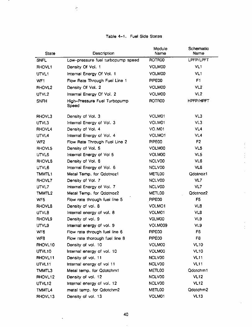
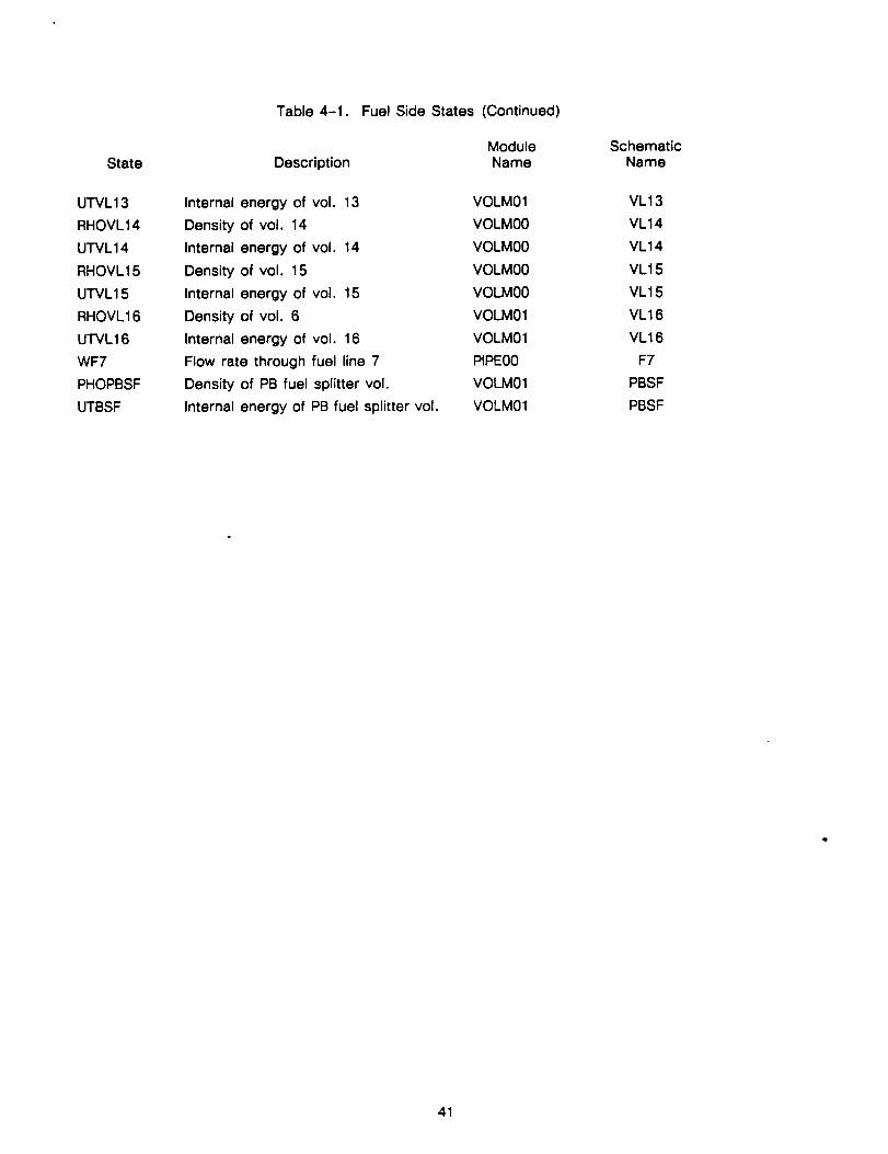
T'T'BE States
The TTBE simulation has 122 states. The states, a description of the states, the module
names where the states are differentiated, and the corresponding schematic names are listed for
the fuel side in Table 4-1, for the oxidizer side in Table 4-2, and for the hot gas side in Table 4-3.
The thermodynamic states, density and internal energy are difficult parameters to iterate. To
overcome this difficulty pressure and enthalpy are iterated to solve the density and internal energy
corrector equations. The thermodynamic states, a description of the thermodynamic states, the
corresponding iteration parameters, and a description of the corresponding iteration parameters
are listed for the fuel side in Table 4-4 and for the oxidizer side in Table 4-5.
"I-FBE Additional Required Balances
Fourteen additional balances are required to close the loop on pressures and temperatures to
achieve a power balance. The iteration parameters and the two balance parameters along with
their descriptions are listed in Table 4-6.
39
State
Table 4-1.
Description
Fuel Side States
ModuleName
SchematicName
SNFL
RHOVL1
UTVL1
WF1
RHOVL2
UTVL2
SNFH
RHOVL3
UTVL3
RHOVL4
UTVL4
WF2
RHOVL5
UTVL5
RHOVL6
UTVL6
TMMTL1
RHOVL7
UTVL7
TMMTL2
WF5
RHOVL8
UTVL8
RHOVL9
UTVL9
WF6
WF8
RHOVL10
UTVL10
RHOVL11
UTVL11
TMMTL3
RHOVL12
U'FVL12
TMMTL4
RHOVL13
Low-pressure fuel turbopump speed
Density Of Vol. 1
Internal Energy Of Vol. 1
Flow Rate Through Fuel Line 1
Density Of Vol. 2
Internal Energy Of Vol. 2
High-Pressure Fuel TurbopumpSpeed
Density of Vol. 3
Internal Energy of Vol. 3
Density of Vol. 4
Internal Energy of Vol. 4
Flow Rate Through Fuel Line 2
Density of Vol. 5
Internal Energy of Vol 5
Density of Vol. 6
Internal Energy of Vol. 6
Metal Temp. for Qdotnozl
Density of Vol. 7
Internal Energy of Vol. 7
Metal Temp. for Qdotnoz2
Flow rate through fuel line 5
Density of vol. 8
Internal energy of vol. 8
Density of vol. 9
Internal energy of vol. 9
Flow rate through fuel line 6
Flow rate thorough fuel line 8
Density of vol. 10
Internal energy of vol. 10
Density of vol. 11
Internal energy of vol 11
Metal temp. for Qdotchml
Density of vol. 12
Internal energy of vol. 12
metal temp. for Qdotchm2
Density of vol. 13
ROTR00
VOLM00
VOLM00
PIPE00
VOLM00
VOLM00
ROTR00
VOLM01
VOLM01
VO.M01
VOLMO1
PIPE00
VOLM00
VOLM00
NCLV00
NCLV00
METL00
NCLV00
NCLV00
METL00
PIPE00
VOLMO1
VOLM01
V0LM00
VOLM009
PIPE00
PIPE00
VOLM00
VOLM00
NCLV00
NCLV00
METL00
NCLV00
NCLV00
METL00
VOLM01
LPFP/LPFT
VL1
VL1
F1
VL2
VL2
HPFP/HPFT
VL3
VL3
VL4
VL4
F2
VL5
VL5
VL6
VL6
Qdotnozl
VL7
VL7
Qdotnoz2
F5
VL8
VL8
VL9
VL9
F6
F8
VL10
VL10
VL11
VL11
Qdotchml
VL12
VL12
Qdotchm2
VL13
4O
State
U'I'VL 13
RHOVL14
UTVL 14
RHOVL15
UTVL15
RHOVL16
UTVL16
WF7
PHOPBSF
UTBSF
Table 4-1. Fuel Side States (Continued)
Module Schematic
Description Name Name
Internal energy of vol. 13
Density of vol. 14
Internal energy of vol. 14
Density of vol. 15
Internal energy of vol. 15
Density of vol. 6
Internal energy of vol. 16
Flow rate through fuel line 7
Density of PB fuel splitter vol.
Internal energy of PB fuel splitter vol.
VOLM01
VOLMO0
VOLMO0
VOLMO0
VOLMO0
VOLM01
VOLM01
PIPEO0
VOLM01
VOLM01
VL13
VL14
VL14
VL15
VL15
VL16
VL16
F7
PBSF
PBSF
41
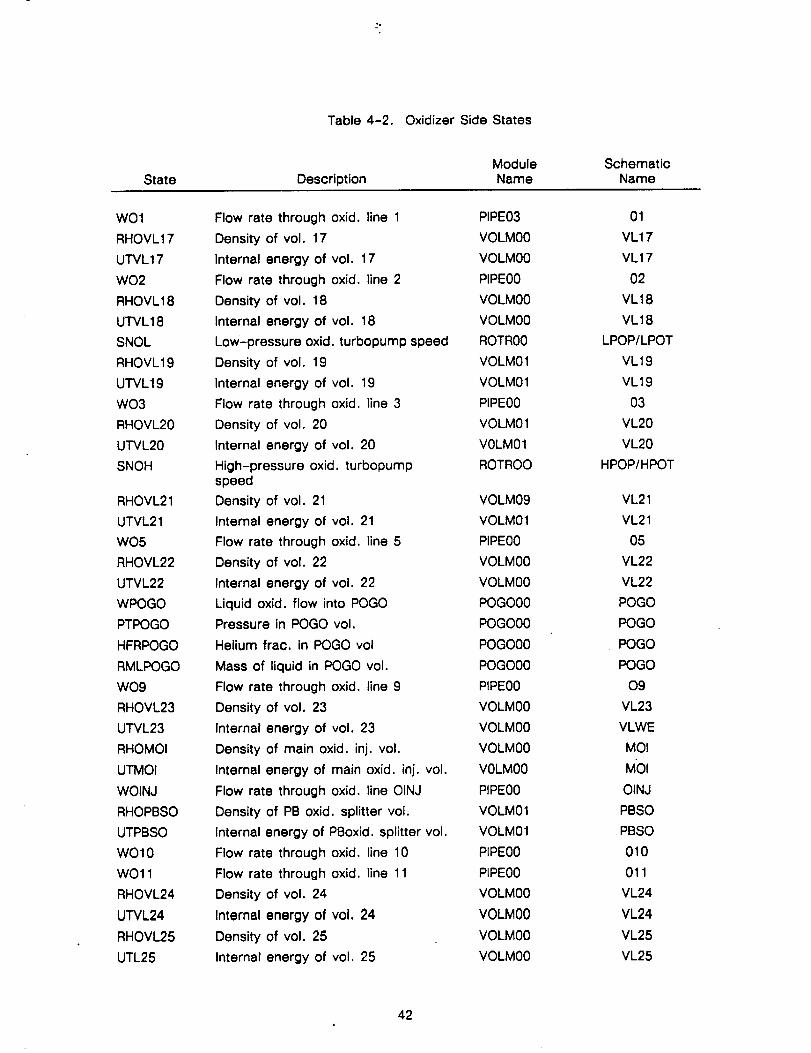
Table 4-2. Oxidizer Side States
StateModule Schematic
Description Name Name
WO1
RHOVL17
UTVL17
WO2
RHOVL18
UTVL18
SNOL
RHOVL19
UTVL19
WO3
RHOVL20
UTVL20
SNOH
RHOVL21
UTVL21
WO5
RHOVL22
UTVL22
WPOGO
PTPOGO
HFRPOGO
RMLPOGO
WO9
RHOVL23
UTVL23
RHOMOI
UTMOI
WOINJ
RHOPBSO
UTPBSO
WO10
WO11
RHOVL24
UTVL24
RHOVL25
UTL25
Flow rate through oxid. line 1
Density of vol. 17
Internal energy of vol. 17
Flow rate through oxid. line 2
Density of vol. 18
Internal energy of vol. 18
Low-pressure oxid. turbopump speed
Density of vol. 19
Internal energy of vol. 19
Flow rate through oxid. line 3
Density of vol. 20
Internal energy of vol. 20
High-pressure oxid. turbopumpspeed
Density of vol. 21
Internal energy of vol. 21
Flow rate through oxid. line 5
Density of vol. 22
Internal energy of vol. 22
Liquid oxid. flow into POGO
Pressure in POGO vol.
Helium frac. in POGO vol
Mass of liquid in POGO vol.
Flow rate through oxid. line 9
Density of vol. 23
Internal energy of vol. 23
Density of main oxid. inj. vol.
Internal energy of main oxid. inj. vol.
Flow rate through oxid. line OINJ
Density of PB oxid. splitter vol.
Internal energy of PBoxid. splitter vol.
Flow rate through oxido line 10
Flow rate through oxid. line 11
Density of vol. 24
Internal energy of vol. 24
Density of vol. 25
Internal energy of vol. 25
PIPE03
VOLM00
VOLM00
PIPE00
VOLM00
VOLM00
ROTR00
VOLM01
VOLM01
PIPE00
VOLM01
VOLM01
ROTROO
VOLM09
VOLM01
PIPE00
VOLM00
VOLM00
POGO00
POGO00
POGO00
POGO00
PIPE00
VOLM00
VOLM00
VOLM00
VOLM00
PIPE00
VOLM01
VOLM01
PIPE00
PIPE00
VOLM00
VOLM00
VOLM00
VOLM00
01
VL17
VL17
02
VL18
VL18
LPOP/LPOT
VL19
VL19
O3
VL20
VL20
HPOP/HPOT
VL21
VL21
O5
VL22
VL22
POGO
POGO
POGO
POGO
09
VL23
VLWE
MOI
MOI
OINJ
PBSO
PBSO
010
011
VL24
VL24
VL25
VL25
42
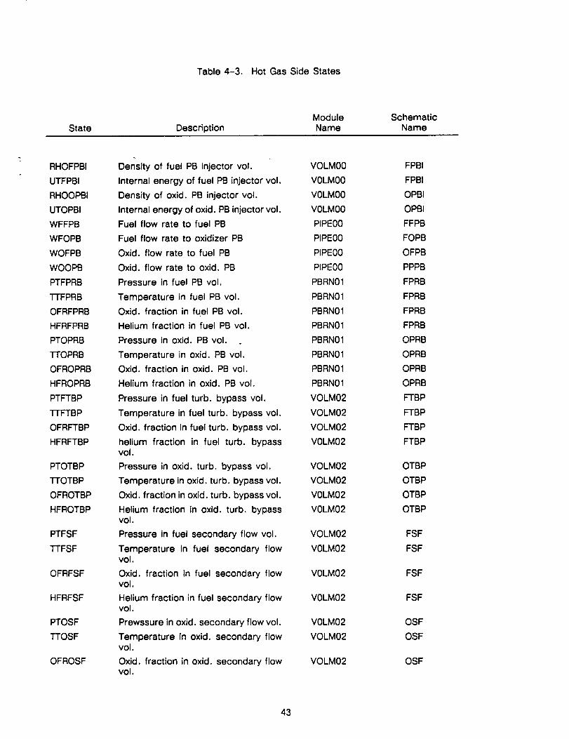
Table 4-3. Hot Gas Side States
State
Module Schematic
Description Name Name
RHOFPBI
UTFPBI
RHOOPBI
UTOPBI
WFFPB
WFOPB
WOFPB
WOOPB
PTFPRB
TTFPRB
OFRFPRB
HFRFPRB
PTOPRB
TTOPRB
OFROPRB
HFROPRB
PTFTBP
1-rFTBP
OFRFTBP
HFRFTBP
PTOTBP
"I-rOTBP
OFROTBP
HFROTBP
PTFSF
TTFSF
OFRFSF
HFRFSF
PTOSF
TTOSF
OFROSF
Density of fuel PB injector vol.
Internal energy of fuel PB injector vol.
Density of oxid, PB injector vol.
Internal energy of oxid. PB injector vol.
Fuel flow rate to fuel PB
Fuel flow rate to oxidizer PB
Oxid. flow rate to fuel PB
Oxid. flow rate to oxid. PB
Pressure in fuel PB vol.
Temperature in fuel PB vol.
Oxid. fraction in fuel PB vol.
Helium fraction in fuel PB vol.
Pressure in oxid. PB vol.
Temperature in oxid. PB vol.
Oxid. fraction in oxid. PB vol.
Helium fraction in oxid. PB vol.
Pressure in fuel turb. bypass vol.
Temperature in fuel turb. bypass vol.
Oxid. fraction in fuel turb. bypass vol.
helium fraction in fuel turb. bypassvol.
Pressure in oxid. turb. bypass vol.
Temperature in oxid. turb. bypass vol.
Oxid. fraction in oxid. turb. bypass vol.
Helium fraction in oxid. turb. bypassvol.
Pressure in fuel secondary flow vcl.
Temperature in fuel secondary flowvol.
Oxid. fraction in fuel secondary flowvol.
Helium fraction in fuel secondary flowvol.
Prewssure in oxid. secondary flow vol.
Temperature in oxid. secondary flowvol.
Oxid. fraction in oxid. secondary flowvol.
VOLM00
VOLM00
VOLM00
VOLM00
PIPE00
PIPE00
PIPE00
PIPE00
PBRN01
PBRN01
PBRN01
PBRN01
PBRN01
PBRN01
PBRN01
PBRN01
VOLM02
VOLM02
VOLM02
VOLM02
VOLM02
VOLM02
VOLM02
VOLM02
VOLM02
V0LM02
VOLM02
VOLM02
VOLM02
VOLM02
VOLM02
FPBI
FPBI
OPBI
OPBI
FFPB
FOPB
OFPB
PPPB
FPRB
FPRB
FPRB
FPRB
OPRB
OPRB
OPRB
OPRB
FTBP
FTBP
FTBP
FTBP
OTBP
OTBP
OTBP
OTBP
FSF
FSF
FSF
FSF
OSF
OSF
OSF
43
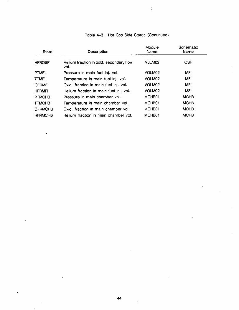
State
Table 4-3. Hot Gas Side States (Continued)
Module Schematic
Description Name Name
HFROSF
PTMFI
TTMFI
OFRMFI
HFRMFI
PTMCHB
TTMCHB
OFRMCHB
HFRMCHB
Helium fraction in oxid. secondary flowvol.
Pressure in main fuel inj. vol.
Temperature in main fuel inj. vol.
Oxid. fraction in main fuel inj. vol.
Helium fraction in main fuel inj. vol.
Pressure in main chamber vol.
Temperature in main chamber vol.
Oxid. fraction in main chamber vol.
Helium fraction in main chamber vol.
V0LM02
VOLM02
VOLM02
VOLM02
VOLM02
MCHB01
MCHB01
MCHB01
MCHB01
OSF
MFI
MFI
MFI
MFI
MCHB
MCHB
MCHB
MCHB
44
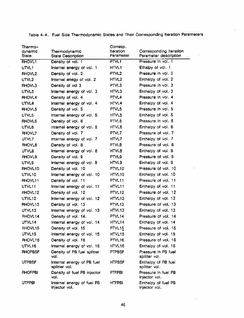
Table4-4. Fuel Side Thermodynamic States and Their Corresponding Iteration Parameters
Thermo- Corresp.
dynamic Thermodynamic IterationState State Description Parameter
Corresponding IterationParameter description
RHOVL1 Density of vol. 1 PTVL1
UTVL1 Internal energy of vol. 1 H'rVL1
RHOVL2 Density of vol. 2 PTVL2
UTVL2 Internal enegy of vol. 2 H'rVL2
RHOVL3 Density of vol 3 P'I'VL3
UTVL3 Internal energy of vol. 3 HTVL3
RHOVL4 Density of vol. 4 PTVL4
UTVL4 Internal energy of vol. 4 HTVL4
RHOVL5 Density of vol. 5 P'rVL5
UTVL5 Internal energy of vol. 5 HTVL5
RHOVL6 Density of vol. 6 PTVL6
U'I'VL6 Internal energy of vol. 6 HTVL6
RHOVL7 Density of vol. 7 PTVL7
UTVL7 Internal energy of vol. 7 HTVL7
RHOVL8 Density of vol. 8 PTVL8
UTVL8 Internal energy of vol. 8 HTVL8
RHOVL9 Density of vol. 9 PTVL9
UTVL9 Internal energy of vol. 9 HTVL9
RHOVLIO Density of vol. 10 PTVL10
UTVLIO Internal energy of vol. 10 HTVL10
RHOVL11 Density of vol. 11 P'I"VL11
UTVL11 Internal energy of vol. 11 H'I"VL11
RHOVL12 Density of vol. 12 PTVL12
UTVL12 Internal energy of vol. 12 HTVL12
RHOVL13 Density of vol. 13 PTVL13
U'I'VL13 Internal energy of vol. 13 HTVL13
RHOVL14 Density of vol, 14. PTVL14
UTVL14 Internal energy of vol. 14 HTVL14
RHOVL15 Density of vol. 15 P'I"VL15
UTVL15 Internal energy of vol. 15 HTVL15
RHOVL16 Density of vol. 16 P'I"VL16
UTVL16 Internal energy of vol. 16 HTVL16
RHOPBSF Density of PB fuel splitter PTPBSFvol.
UTPBSF Internal energy of PB fuel HTPBSFsplitter vol.
RHOFPBI Density of fuel PB injector PTFPBIvol.
UTFPBI Internal energy of fuel PB HTFPBIinjector vol,
Pressure in vol. 1
Ethalpy of vol. 1
Pressure in vol. 2
Enthalpy of vol. 2
Pressure in vol. 3
Enthalpy of vol. 3
Pressure in vol. 4
Enthalpy of vol. 4
Pressure in vol. 5
Enthalpy of vol. 5
Pressure in vol. 6
Enthalpy of vol. 6
Pressure of vol. 7
Enthalpy of vol. 7
Pressure of vol. 8
Enthalpy of vol. 8
Pressure of vol. 9
Enthalpy of vol. 9
Pressure of vol. 10
Enthalpy of vol. 10
Pressure of vol. 11
Enthalpy of vol. 11
Pressure of vol. 12
• Enthalpy of vol. 12
Pressure of vol. 13
Enthalpy of vol. 13
Pressure of vol. 14
Enthalpy of vol, 14
Pressure of vol. 15
Enthalpy of vol. 15
Pressure of vol. 16
Enthalpy of vol. 16
Pressure in PB fuel
splitter vol.
Enthalpy of PB fuelsplitter vol.
Pressure in fuel PB
Injector vol.
Enthalpy of fuel PBInjector vol.
45
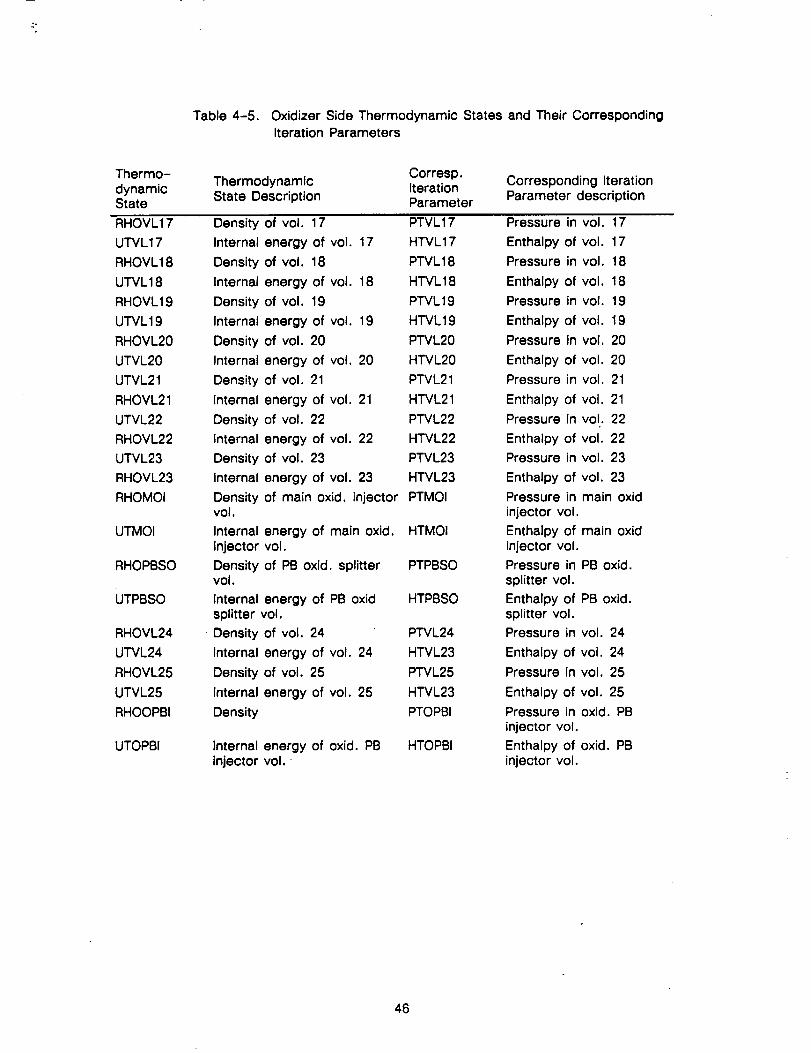
Table 4-5. Oxidizer Side Thermodynamic States and Their CorrespondingIteration Parameters
Thermo-
dynamicState
ThermodynamicState Description
Corresp.IterationParameter
Corresponding IterationParameter description
RHOVL17
UTVL17
RHOVL18
UTVL18
RHOVL19
UTVL19
RHOVL20
UTVL20
UTVL21
RHOVL21
UTVL22
RHOVL22
UTVL23
RHOVL23
RHOMOI
UTMOI
RHOPBSO
UTPBSO
RHOVL24
UTVL24
RHOVL25
UTVL25
RHOOPBI
UTOPBI
Density of vol. 17 PTVL17 Pressure in vol. 17
Internal energy of vol. 17 H'rVL17 Enthalpy of vol. 17
Density of vol. 18 PTVL18 Pressure in vol. 18
Internal energy of vol. 18 H'rVL18 Enthalpy of vol. 18
Density of vol. 19 P'rVL19 Pressure in vol. 19
Internal energy of vol. 19 HTVL19 Enthalpy of vol. 19
Density of vol. 20 PTVL20 Pressure in vol. 20
Internal energy of vol, 20 HTVL20 Enthalpy of vol. 20
Density of vol. 21 PTVL21 Pressure in vol. 21
Internal energy of vol. 21 HTVL21 Enthalpy of vol. 21
Density of vol. 22 PTVL22 Pressure in vol. 22
Internal energy of vol. 22 HTVL22 Enthalpy of vol. 22
Density of vol. 23 PTVL23 Pressure in vol. 23
Internal energy of vol. 23 HTVL23 Enthalpy of vol. 23
Density of main oxid. injector PTMOI Pressure in main oxidvol. injector vol.
Internal energy of main oxid. HTMOI Enthalpy of main oxidinjector vol. injector vol.
Density of PB oxid. splitter PTPBSO Pressure in PB oxid.vol. splitter vol.
Internal energy of PB oxid HTPBSO Enthalpy of PB oxid.splitter vol. splitter vol.
Density of vol. 24 PTVL24 Pressure in vol. 24
Internal energy of vol. 24 HTVL23 Enthalpy of vol. 24
Density of vol. 25 PTVL25 Pressure in vol. 25
Internal energy of vol. 25 HTVL23 Enthalpy of vol. 25
Density PTOPBI Pressure in oxid. PBinjector vol.
Internal energy of oxid. PB HTOPBI Enthalpy of oxid. PBinjector vol, injector vol.
46
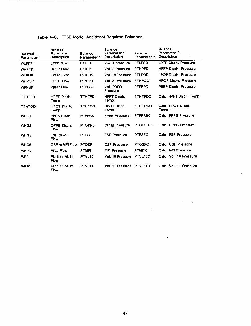
Table 4-6. TTBE Model Additional Required Balances
IteratedParameter
Iterated BalanceParameter Balance Parameter 1Description Parameter 1 Description
BalanceParameter 2
BalanceParameter 2Description
WLPFP LPFP flow PTVL1
WHPFP HPFP Flow PTVL3
WLPOP LPOP Flow PTVL19
WHPOP HPOP Flow PTVL21
WPRBP PBRP Flow PTPBSO
TTHTFD
TTHTOD
WHG1
WHG2
WHG5
WHG6
WFINJ
WF9
WF10
HPFT Dlsch. TTHTFDTemp.
HPOT Dlsch. TTHTODTemp.
FPRB DIsch. PTFPRBFlow
OPRB Dlsch. PTOPRBFlow
FSF to MFI PTFSFFlow
OSFto MFI Flow PTOSF
FINJ Flow PTMFI
FL10 to VL11 PTVL10Flow
FL11 to VL12 PTVL11Flow
Vol. 1 pressure PTLPFD
Vol. 3 Pressure PTHPFD
Vol. 19 Pressure PTLPOD
Vol. 21 Pressure PTHPOD
Vol. PBSO PTPBPDPressure
HPFT Dlsch. TTHTFDCTemp.
HPOT Dlsch. TTHTODCTemp.
FPRB Pressure PTFPRBC
OPRB Pressure PTOPRBC
FSF Pressure PTFSFC
OSF Pressure PTOSFC
MFI Pressure PTMFIC
Vol. 10 Pressure PTVL10C
Vol. 11 Pressure PTVL11C
LPFP Disch. Pressure
HPFP Dlsch. Pressure
LPOP Dlsch. Pressure
HPOP Disch. Pressure
PRBP Dlsch. Pressure
Calc. HPFT Dlsch. Temp.
Calc. HPOT Disch.Temp.
Calc. FPRB Pressure
Calc. OPRB Pressure
Calc. FSF Pressure
Calc. OSF Pressure
Calc. MFI Pressure
Calc. Vol. 10 Pressure
Calc. Vol. 11 Pressure
47

This page left intentionally blank.
48
SECTION V
SYSTEM TESTING AND VERIFICATION
System simulations were generated and operated to verify the proper operation of the
ROCETS system. Math model simulations utilized for this testing included:
• Simple TTBE Model
• Detailed LOX side Model
• Detailed TTBE Model
• Sub-set Model
Because the models did not use all the same equations and calculations of the SSME DTM
(Reference 2), the resulting predictions were not expected to reproduce exactly the DTM.
However, comparisons to the DTM results were used as a guide that the models were functioning
properly in the ROCETS system,
5.1 SIMPLE TTBE MODEL TEST
The simple "I-I'BE Model (as defined in Section 4.1) had 55 state variables and 2 algebraic
loops. The initial test was obtaining a steady state balance at 100% RPL by driving the state
derivatives"to zero and closing the algebraic loops (to within a specific tolerance). This
demonstrated the capability of the ROCETS system to converge a rocket simulation to a
steady-state point without running a transient. Transient capability was demonstrated by running
the simple T'I'BE simulation with small perturbations of preburner valve areas about the 100% RPL
point.
Additional algebraic loops (balances) were placed in the model to set preburner valve
coefficients at points other than 100% RPL. The fuel preburner valve coefficient was iterated until
chamber pressure (PTMCHB) was equal to the request:
PTMCHBRequest = PTMCHB100 RPL X %RPL
The LOX preburner valve coefficient was iterated until chamber oxidizer fraction (OFRMCHB)
was equal to a constant value of 0.865. (this is equivalent to a mixture ratio of 6.407). Figure
5-1 shows main chamber pressure and oxidizer fraction as a function of RPL. A series of
steady-state points between 60% and 119% RPL were then run with the solver iterating on valve
coefficients until chamber pressure and LOX fraction were satisfied, this demonstrated the ability
of the model to use the solver as a means to set a model parameter based on an input constraint.
Output of the run gives a reference steady-state operating characteristic for the model and
provides data for SMITE guess curves. Figure 5-2 shows turbine speeds as a function of RPL.
49PRECEDING PAGE BLANK NOT F!LMED
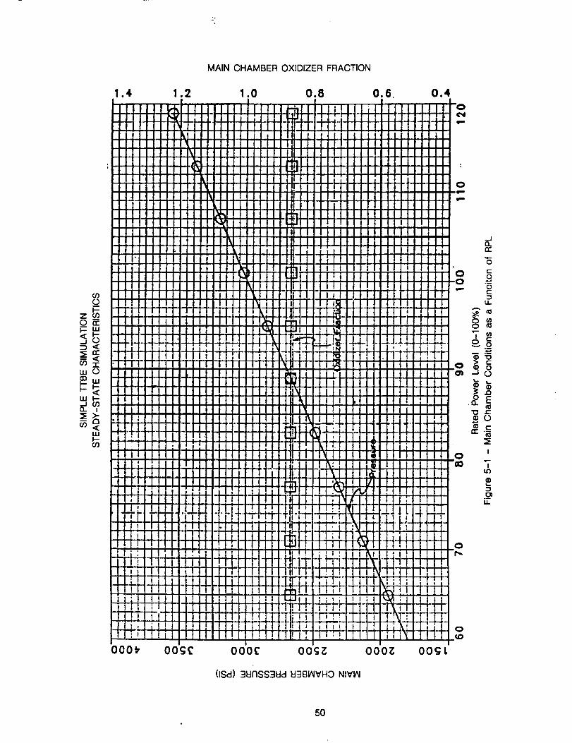
wot_
UJ l--,_l
uJ1--O3
MAIN CHAMBER OXIDIZER FRACTION
1.4 1.2 1.0 0.8 0.6 0.4
000_ OOg£ 000£ OOC;Z 000_;
(ISd) 3unss3ud EI3B_VHO NIV_
O0_L
/
n_
0
C
0
o
U-
.Q
.a. E
C_
I
I
@
._ou.
50b
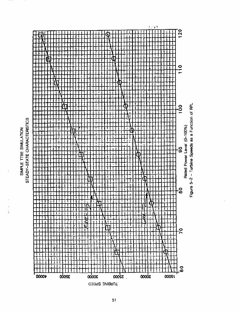
l--
w 0n7
_ t7
wi-
n,-
oit
O.
I
LI_
51

Thesteady-state data as a function of RPL was tabularized and used to construct anopen-loop control with RPL request input and valve data area requests calculated from the table.The valve request were put through a first order lag to simulate actuator dynamics. Gross throttletransients were run by inputting an RPL request as a function of time and using the open-loopcontrol to provide valve areas. Figures 5-3 and 5-4 show results of a transient run from 100% to65% RPL decel and figures 5-5 and 5-6 show a transient run from 65% to 109% RPL. These testwith the simple TTBE model demonstrated the ability of ROCETS to obtain a steady-state balance,obtain steady-state valve schedules based on imposed constraints, and to operate transiently.
52
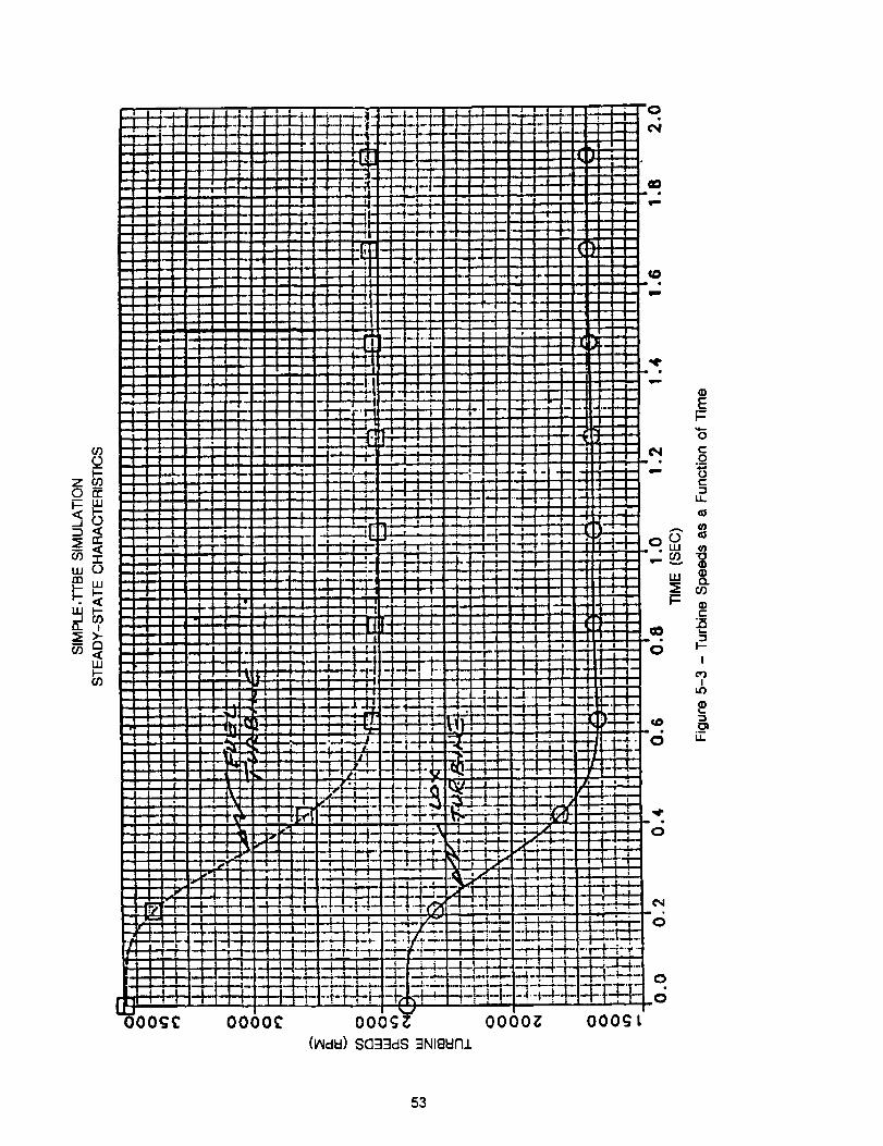
(,0
Q
"T"WO
W
<w
£#')
-i_
.--i--
m4
!
i_
i
i
iii
i
iI
i
.|
!
!!
ij
! .! -
-i--L
i:
I "
: 4.
!!-i-L..
ElH-,
P: -_-7
iii! ! t
00_
"-'*" *" l I _ i
lm.ml , .:
-- "-I"l.'iil -- : :I i
:- " I II _!
_- LI.- .: : ;
: I,*- " _ i i
i ii i i
iii i J ,! IP_: -- l I
I I
ill i i." -'1 " ;
.r'_ ii
i :-- i i
-_ , I;...i,,i.,, ,
:_ -i !_i it --I--.--
:, -H ii_ I- _ ! _ _
:_'-_ ii i! I t
; "';; i
_ _ ,;-i-;J i • i-'r-' ;' I1 I _[ 7 ; i r,
"; -Fi_-_. - b- r-
i i _'_._+ -- II i " i i
i i.,'i _IiI "• - " n [
.... ," i i i i i I_ll_i i i
' 6--i_
FLi.4: _
L+--+_,. _ _ K-T. i- _ _ i..... ill p _-- l p LLI-
rill. !
000_ 0000_
(ItidW) 8C]33d8 _NIBWnl
_m
_ 0
iOe
m
iO
n
,illll
m
J
!
i-
Li..
i"
r-
i
!
Hl-i
i=!
!
i*" 0
0
000¢_ t
(D
I.-
0
e-.90c:3
u,.
(B
l-
I--
I
I
3
u.
53
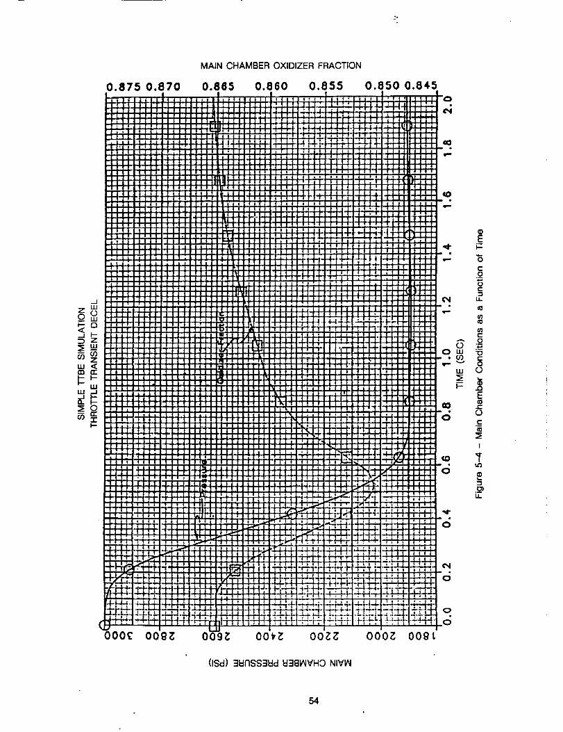
"o
u,.I <
I='-I,.1,.I
uJ _1
t-
MAIN CHAMBER OXIDIZER FRACTION
0.875 0.870 0.865 0.880
O00C OOgZ O09Z OOt_
(ISd) ::IEII'ISS::::IEId EF:IB_VHO NIVI/_
EF-
0t.-._o
IJ.
e_
el)
C:
o
t-O
(3
.JOE
.J_
(3t-
I
_r
LL
54
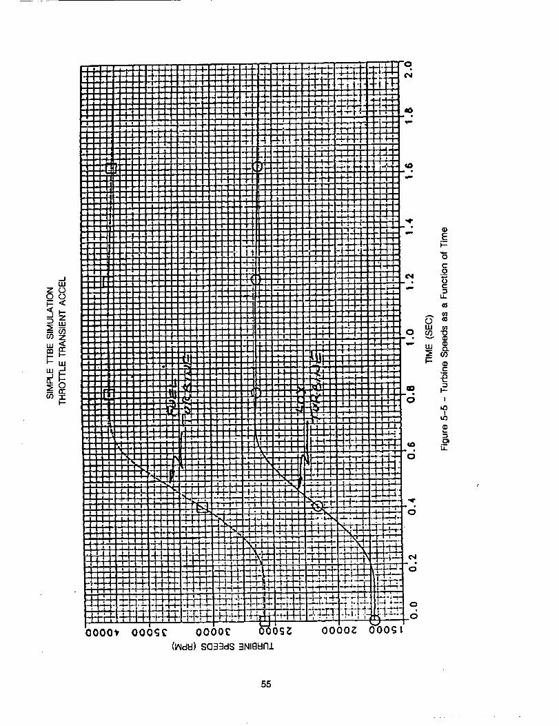
_.1w
Zoo°
CO
I;O
I:z_-I.U
I.-
0000_ ooo_c 000o£ _-60_
(I,NclEI) 803::Id8 3NIBId171
0
¢4
c;
Ei=4,--
0
.9
¢:
LL.
cO ©w co
v
"' 8.co
i
I-- _)e-
l--
I
o_
55
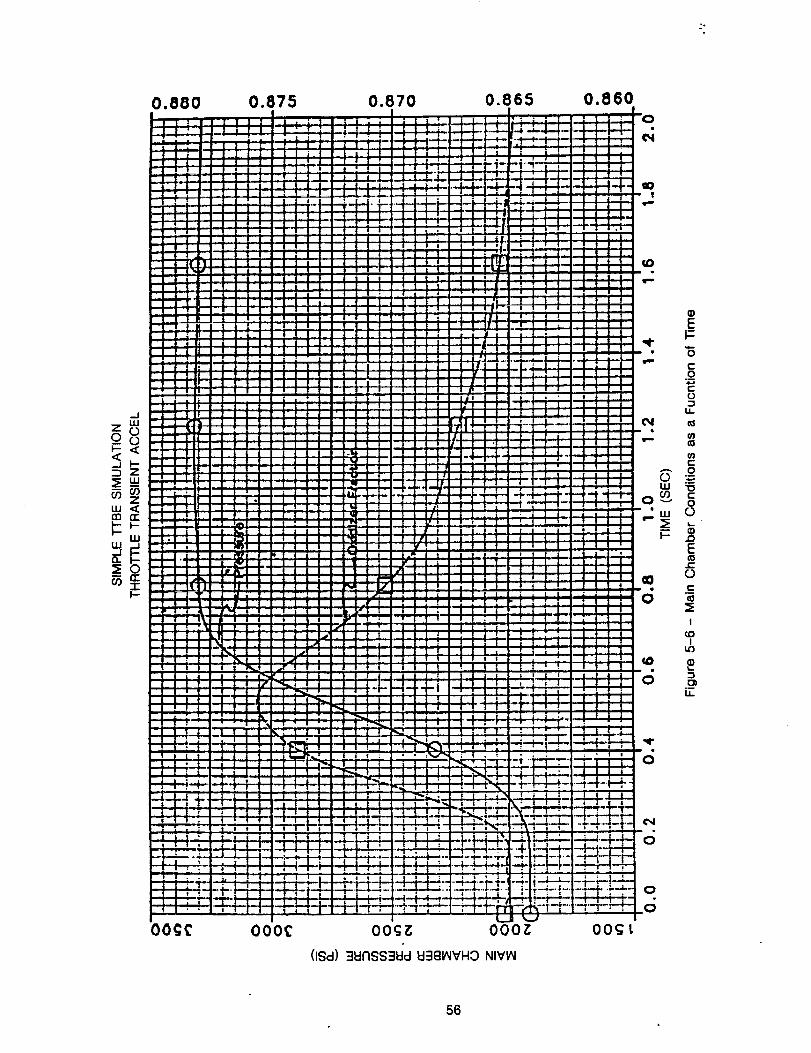
--J
z_0
<
ul
p_w_
I--
0.880[ -T I I I
: I .... I i I I
T
-I i
" i
) !...iI -
i __._
...1-_ = .:
2i •
I '
" i.i 2--I
__ "i -2 :
-I _ -I "
: i i_:| i ";
- i --_
i =: ,. If;
--'i--_ _i :j : _! - _:.
; |,
-! , )! ! .
i _ |l 'I
L
! i l
I-! ! I,
I _ : |
i I
. • I" | _ - ! ,
!
;
__,_,_- -..t___ .J__,_
0.875,r
[
r
!
i
q
i
i]
I
]
.iI
J
.]
I-
I
]
I
i
i ,,, ,i
! I i t• - ! i
F_-i LT.i-i--11- F
000_
0.870 0.885 0.860IJL_ i
b4!ii [
__ k |I #
--_l i --- | •
I'" FF ;
I I
I
i .i i!
_ I l--
!
iiii: _-i -!-
I| i
I
!
!, . I
i
i-_, :
tl,
_. |
1',4,, !
i,_. ,
._'-- -, _
!
!
Ft
1%.!
,,_±
i
t
i " _-'EI i ! i
i i | i
_,,
l I l r_
OOgg OOgt
(ISd) 31::lNSS38d 8=IBV4VHO NIVIAI
o.
._E
0
E
._o
0
3
P ill
E
e-
_ 0
!
I
6 _LL
d
'6
o
6
56
5.2 DETAILED LOX SIDE MODEL TEST
The Oxidizer side of the detailed Technology Test Bed Engine (TTBE) model was configured to
verify component fidelity and basic model definition. Figure 5-7 shows a schematic of the model
with the station names labeled. This version of the model did not include a pogo system, which
was added later,
In order to verify the configured model, a shutdown transient was executed by giving the
detailed Iox side model transient inputs from the Rocketdyne Digital Transient Model (DTM) of
reference 2. These inputs were the high-pressure rotor speed, the low-pressure pump inlet
pressure, the pogo flowrate, and the oxidizer flowrates to the preburners and main chamber.
Figures 5-8 and 5-9 show these inputs as a function of time. Some results from operating the
lox-side TrBE simulation are shown in Figures 5-10 to 5-13 with overlays to the DTM predictions.
A 10ms time step, which is approximately 50 times larger than the DTM, was used with the implicit
integration scheme of ROCETS.
With 5 passes, or less, at each time step to obtain the implicit integration, an order of
magnitude savings exist in computer calculations for a simulated transient. Figure 5-10 & 5-11
presents the low pressure pump and line 2 flowrates for both simulations showing excellent
agreement. The comparisons between the two simulations of low pressure rotor speeds (Figure
5-12) and mixer 2 total pressure (figure 5-13) are also very good transiently with only some initial
steady-state level differences.
57
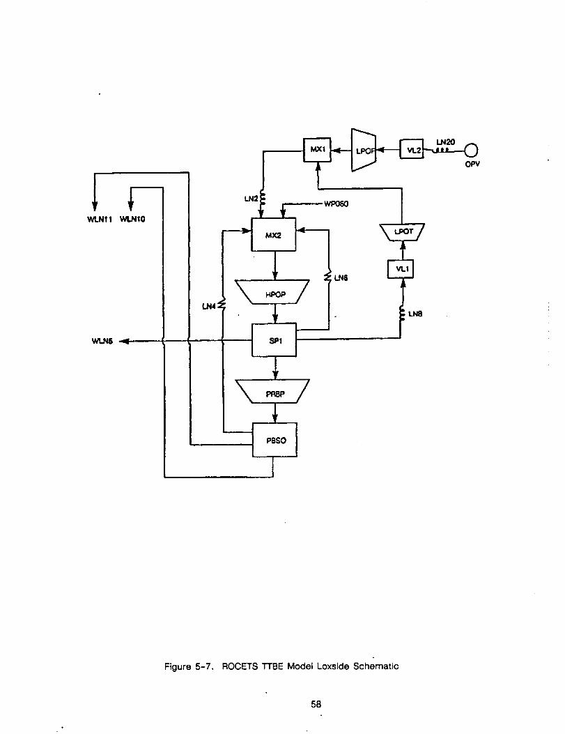
I
-t.,o i
Figure 5-7. ROCETS TTBE Model Loxside Schematic
58
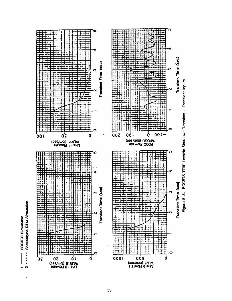
I
ii _ :::i.,,,,&- 4--
t ...
i |
! :
i :
.: ;i
-4-_4
: ' i ! l •
- ,-f-- i , } 1
_.,v- F -'t----t -' "T-_ :-1_ -J.._La _
O0 1 " Og 0(oos_.fl I.1.1¢_
ole_,_:l !,I, out1
llJlll|l Ildl4111:l] ;
rql::_':: I|,,,_ ',I.t-H-HI-_
!!! _1_,._..
T 7 _'_".'_'J'7 tl! t ! _-I i-L'! I
i:"_-_ _'.'i_li_l
i T't'_._t" "t'r'.-rm,._fl
, I - d i J _ " i J
- _ _-i-_,' _i -_
-t- p. _- ._.'..,- H'.f- -t-*/_
. :_ :.:_ :._:,F,'_'-; 0_" o_ ol. o, (ooi/u.,ql) 0 tNl'l_
• - _ Olll_ld 0[ gull
++_i +t-4-1"i'_ ]
l_._: I +l-
fN-tl
h.!-H
N
,-_4,-_ '_"""'1"_ _
llii:7i;
i-m..j.-. Y_
' i7 ; "_..t_ _
• _
"_4 ft'"'" ......_i' 4t.._,-v-i-_"_.1__i', "__ I_-
4i'P'_,ff- il,i _,7:_41-1"t"_t _,_ _1-_ _._-_._!" _ _ _ i_ _ -_iLli_ I : I:i ..i-;,._.-_
oo_ oo_ o oot- I(ooilu_) O00dM
] I I I I I ! I I I tlTTI ? 1 I I I ll_)
I I I ] l-T! /11/ IIi i i t I:1 _l-rl "^1.1.1-I i i i i _ i'? _!
: ,' I t I [ I I I I I I _ I i I I ._1 l I ] I i I I ! I ! I l l I l I ! L!
.i.d_H A_A i I I i i i I j rl 1 I
I" I _L: : 1 II • - I I
L.' k! , , i_ i [ _ i , I , ! , , I _r
..r ; , ; ! i i _ I j I 1"1 ;1 . ! I
-r_-. "! 144 4 I'I', H"i I o__-+,.b+i_._,_I o=Am_.:I, I::_,t <f,
.----_: ---,-'_- -. -r _• +e, -_.44.'_qFM_-_q:._t <"--_,.._ t_, ;_-: t---_]"_:_:._ _[:_ 7_ _.
-T"-r" i . t',_" .,_ _,1 ,_i I " , , , , i _ i-_ l-i-H., _!- '_._ 4
_1_: ...... ' " ""'"'_ "" "r'i";""-_-.- ! _-!._-I_ -..!
lOOt 00¢3 0
(oes/wclfl SN'IMO.li_._3 q OUfl
59
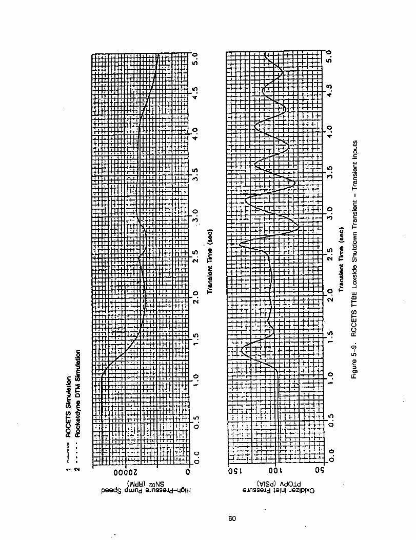
I
L.
-i_+-
oCt--t-.M-L
N-444-
,,t-t-1-•.t.,..-t o
° ..
-4-+,+-4 ' '
TT'r"
I | r
.! i
-kJ:_:
.-I.._L,
0_[
eJnsseJd _elUl Jez!p!xo
0
0
d
6O
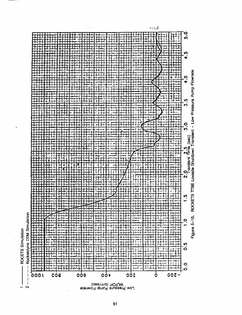
c
E
w
lO00tII
cog OOy o(
(oes/Luq) dOd-I_Ae_,eJ_Ol4 duJnd eJnsseJd MO'I
O
i1
E
",4 _
O
,4 'E
Oe-
I--
_®
wm
"- v
8
O "-• I
O
O
61
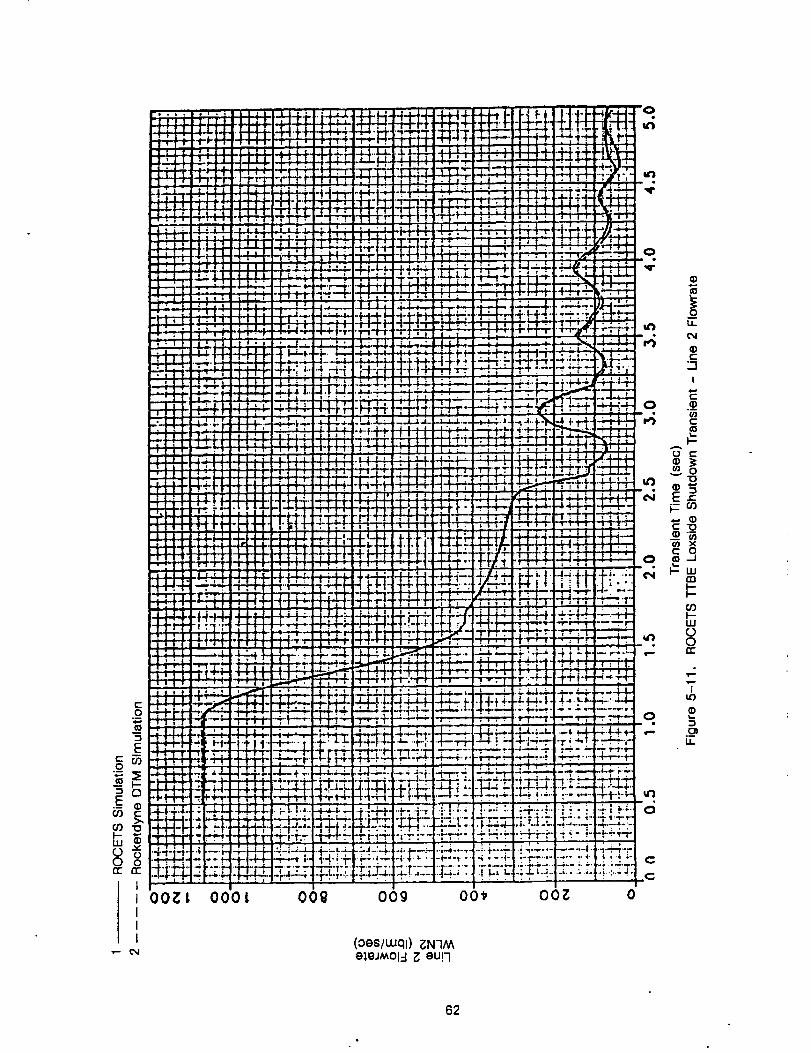
000| oot
(oes/wql) _N7_eleJA_Ol-I _ eu!7
62
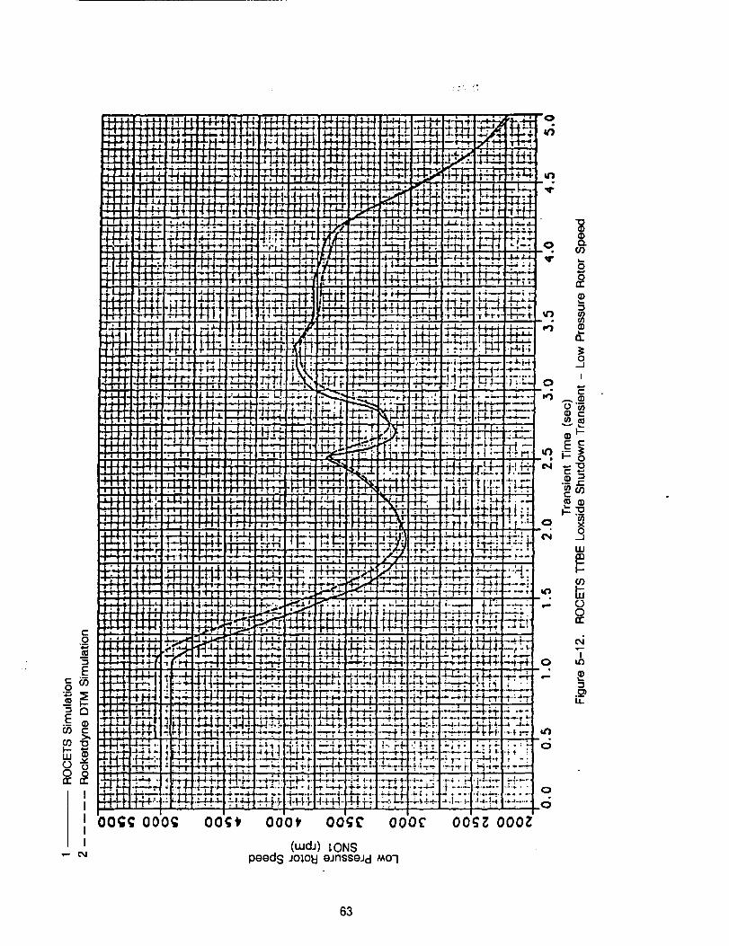
00_ 000_
o
u'3
T
"o
0 o.. or)
3rc
u,J
0.
oIi
io
i---a)
o
e-
o ×o
LLIal
•,- 00
I
.__
o
63
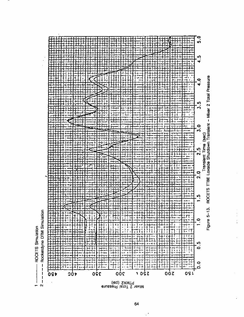
0
E8_
Iii
0 o
OgS,
• - CM
"E-_D"4_'O"
__ +-'0 "!"
_,_'-, _" ,
:;;7
,@.4 oot-
• • t"
t9 _
: _'.-Ir --P
:t:22:2r , z
i._-e,
,a.. _'._ ;..
qP4 I
L';Piiq
: o .
_:r!:
.+_,..m,_,
4. t,.._.4
_. o..o
T';."Ti
I • 1
O(
0
A-i
0
X
I
(!sd) _Xl_ldoJnssoJd ImOJ. _ JOX!l_
64
5,3 DETAILED I-rBE MODEL TEST ;'_
The complete detailed T'rBE model was balanced at 100% RPL and compared to the DTM. Asshown on Table 5-1, the balance condition was close to the values of the DTM parameters.Various open loop transients in main stage operation were exercised to verify proper operation of
the model operating in the ROCETS system. Figures 5-14 through 5-21 present the results of oneof these experiments. The engine was initiated at 100% RPL, and then the fuel preburner valvewas closed 10% (Figure 5-14). The transient response to selected parameters of flows, pressure,speeds, and pogo flowrate and pressure are presented on Figure 5-15 through 5-21.
65
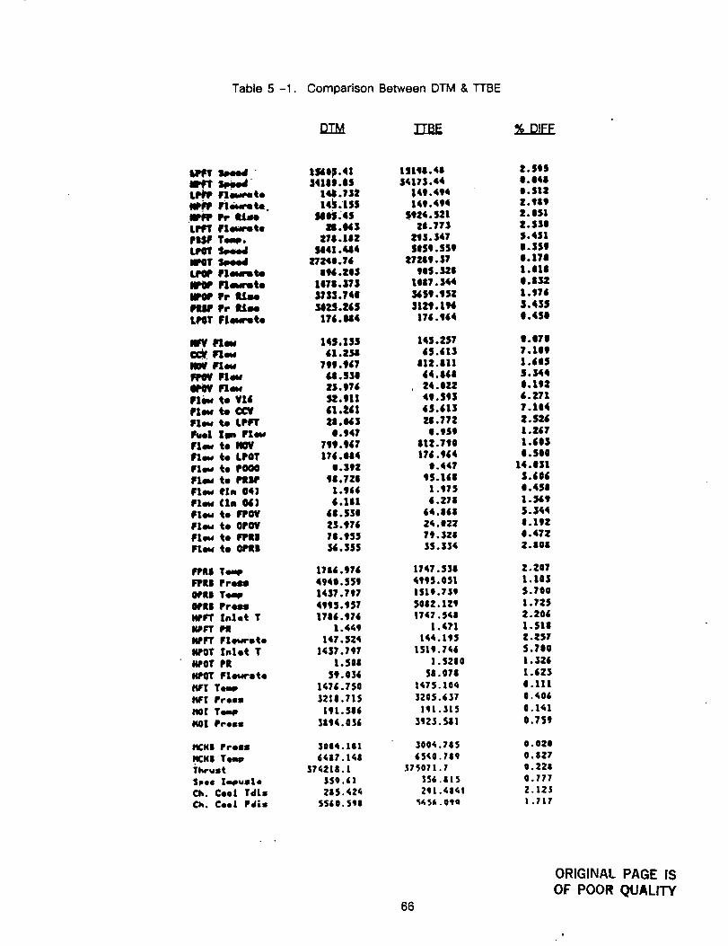
Table 5 -1. Comparison Between DTM & TTBE
DTM TrBE _..DJ£E
Speed tSde_.41 tstqe.4e 2.00sJ8_r speed 3418J.85 |4175.44 |, 048
Fle,_e to 14,J1.732 149.494 0. $12N_P. Fte_ret_. 141,150 149.494 Z. 949JlP_ Pr time MOSj4S 511,.521 t.051uq_r Flewrete N.0_3 20.77] Z.SSePI65F Temp. 278,182 _"13. $47 5,451LPOY _ 5041.444 50S0. SSg g.S$gNPOT Sp4md 27241.76 t7n9. $7 I. 178LPOP Flm_e 096 .Z05 IIS. 328 1.01=Ig_ Flewroto 1078, |7S 1087. 344 0.832NPOP Pr JULge $753,740 3459.t$Z 1.570PtOP Pr Rime S825.t65 3121.1_ 3,435
LlqIY Fleurete 176 • U4 176. t64 0.4S0
M_f Neu 14S,105 140.257 1.070C_ Irxew 61.2_8 60.613 7,109
NOV Irlme 799,967 812.111 1.605PPeV Irlew U.s$g 64.868 5,544
0P0V Flew 23,976 . 24.0?_ 0o192Flmt te Vt4 52,911 49.593 6.271Plew _e CCV 61.261 65.6|3 7,104
Flew _e LPFT 28,_$ _8.772 2.526Fro1 Xjm Flew 0.947 0.IS9 1.267Flew to NOV 799.967 812,710 1.605Flew to LPOT 176.084 176.964 0,500Flew te POO0 1.392 0.447 14.031Flew to i_llP 9/.72| $5.|60 $.606Flew 01, 041 1.966 1.975 0.450
Ptw (ln 0_! 6.18& 6,271 1._9Flew te FPOV 68.531 64.|60 $.344Plew te 0POV 11S.976 24.021 0,192Flew to Irl_ll 78.955 79.328 0.472Pt=w t. Ol_| 36.355 15.334 2.808
FPJtl Teeqm 1786.976 1747. 538 2.207
FPJtJ Fr44_n 4940.559 4995. 051 1.10JOtJLI Temp 1437.797 1510.739 S.700OPtJ Free_ 4995.957 5062. 129 1.72SHPFT [slot T 1786.976 1747.5_8 2.206
14PITTPit 1.449 1.471 l.Sl|HPFT Flewrote 147 .SZ4 144.195 Z.Z$7
14POT Inlet Y 1437.797 151t.746 5.70014POT PR 1. S 00 1. 5210 1.326JCPOT Irxewrste 59,036 58.078 1.623
t_r! Teap 1476.750 1,75.10_ 0.111IqF'Z Pros: 3218.715 3205.637 0._06tlOI Tom, |9L.586 lql.SI$ _.i_l
IqO| Press 3tq¢ .036 392_. 581 0.759
15CN| Press 3004.18! 300_.785 0.020
HCH| Tee_ 6487.1_8 65A0.789 0.027Thrust 37_218.! _7_0P1,7 0.228Shoe Z_s&e 150.61 556,815 0.777
Ch. ¢eeL Tdls _85.42_ 291._8_t 2.12JCk. ¢oeL Pdls 5560.548 5_5_.0_e 1.717
66
ORIGINAL PAGE ISOF POOR QUALITY
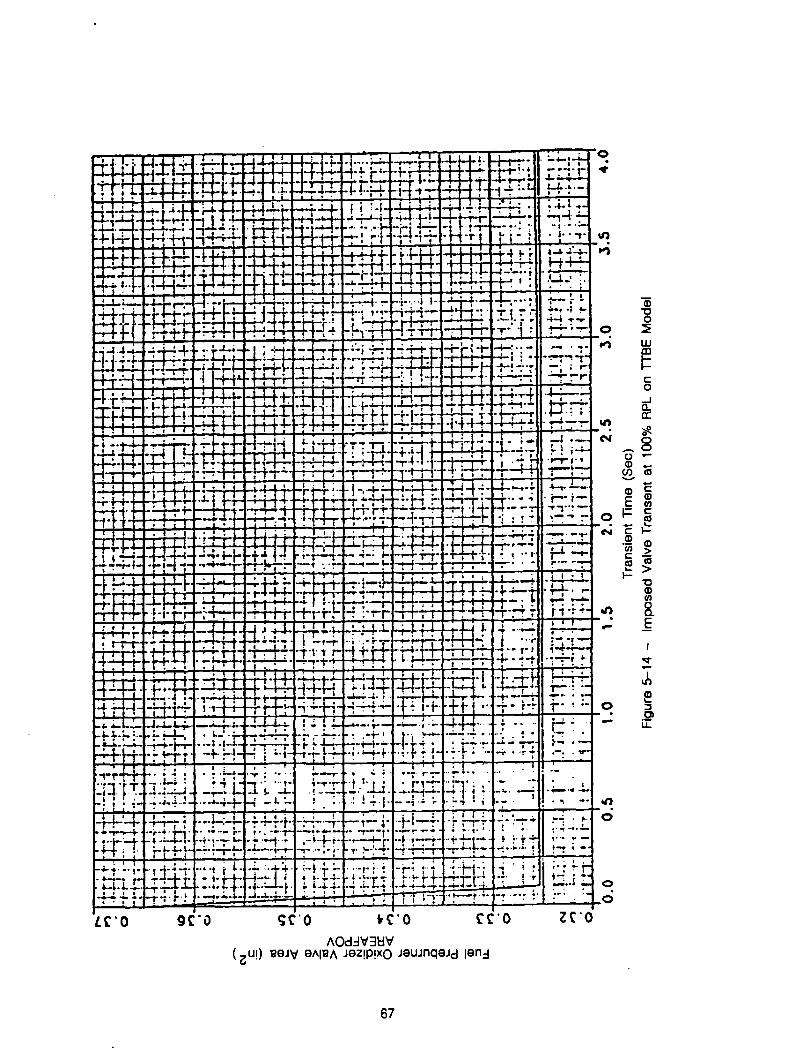
L_'O
0
o
LU
O
er
till
C i'--¢)
I-
(no
.- __EI
,q-
0.- ,_1)
LL
_n
o
o
o
67
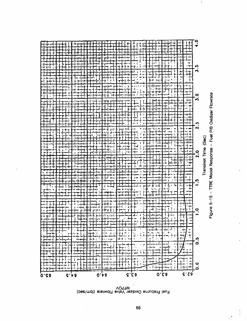
- -" ;_sl rl-!l _.;u4' .M,_,.I J ,, ! f ; '! " ' "',,,, ''lJ "
"+ I ! I [! :l ] I ' i-r +' +Frt; " , -+ ' _' " : + '
+'_+]+.'.+ L._ " ' " ; . .+ :. ..........++-. .-r, + .... l-fi:_+ • ++ '+'I +
: FT _+'_-)'+,;,,'+_+TI :; __! _.i:_4,, __. .........-, +,+.+.• 4..11- ._ - • : .... p- +-+-_-• I-, '-
_, If',._ -l"_i- ± .'. " _fl- -Tr,- " ' "
--,,+''"-++ +'::++++ :+";++++++:"
++-_,..-++++.,+ +-.+__+. -e_,_ ,=.,,., ,_. .... , . ,_-_, + _+-, ,hH- i,_+-+. _-- £" -'2 -'-"-+-:--+::--, + . .. . ,-r--i--_.. iI ; -- +-
+.+ +--:++'++•+.J_L_: " +--+-+" -+ _" ..-S-+..4.# -+-. -.--'' _ __ _ i • _ . , "__ '_ "
-" , r i+ +I_+._rq+_+,.T--. _+::-+-+.,-:_.+,+_4.... )- +-+. L.- -- -.++ Ti r+, • + ? " -_r.- " _-.-_"""-_..--._._,-_.- -_-'- '- -.a '-.i.,.; -.'--'_!-_-+'..:-_. • i -4.i'' "
..., ,- : -+_ ..... ._... !._..+.,._+ -"I _+'" " _ "" , , " _ 0, ' ': .+ 1 ; _t_ r +_ i J_ • ,. F_ "" .- • ' _ , ,, ' i .... .,.i
: Fi-; r _ _ _' + .... _ • -_ _ _--i -_ "I-I I ;" _+_" _ _ I
" . + . l + i 17 i .+I_ I . . Ill. I . -- .+ +++ _+:_ • + ..... i + 17.. ,+':'I ; . I • , tl , , ' I I i , I ; , _ ; .q
• , :I I , l+ • : ; _ i i ._ - _i , , ,+ • ' • _ + , I : l- , ¶ _ :J
i • • • • • ° • • i . i t . • • s
• " , • I l Ill " I L , , * l i ; I I • + L ' • , I " -- . + . Ip --"
• I I • , I , i I I + I I I . . I , i I i + l • • - + "l .J + I , .--I+ -..... I + . _ i __ ,_ • I ' "
• • • . i i | I I -- ! _ • . ••.,..... t.--,.---++-r',-r-r........ +"-""",'-", -'l";-; ; ""- t......-"|-I-.+-:.-----_P+_,l.,_- -,--.._--+*-_-._-_:- ,,,--_1,---,..+-+-.s-._--++-,. ....... -'+-_'-.--;-_-t"_' i- -'--I-:_ _' "'_ 4+_L_ -L4_.' -- --."' --..._r_ • , :4-_P-' ++,_._--- -; '.--+-I
+ • " • • I • • • ' -- i • - " l_ . .=i . , • . . _ . _ • • _ • _
& " • ! • i I • • ; ._ ' - . • & +. ' , . i ¢ J : ,_ I ;
-- * i • i _ I I I • o . - . . - I + i -
l | • • _ i + • o @ _* • i $ , • _i - |. • l • • l • + • • _ j ! j
TT-T'-T't", . ',T'P't-F/ ,._Y__ -, .__'__-_ ' , .-r-+"T'r'. _. "" ,_"_.'_• . . - - - . ; . -- , • , ....
• / . # • P + " " • .: ' ' " - - - L •
...... .... ....J'-"i- --. • t ' • "+ i .-.r.i-. I', " " ""_ '-'; ' , "" "-".'i_!:Z-T.,. : ,-.-_i:. ::r.:,.,.__.+...+_-.... ,.,-,..,, .....,...+--........ I+,-,1:..,.Il • _ l i • i | -- - i -- " i ' • • , - I _ i i
,.m+. --+l--..+ .(.._,=.,_. ,+%.,41.. -. ..... __" .=_ .4 • .m - " I .- + + * .i-i.-l. l• • • • i ' I • - • l , " I ' il - i _,r
I , • il ' _ + I " i m I
t I I t _ , : " • , , I] t , -- ----| : • i " t i ' / - / _--'_"1% • I. i-,,,.-I- --i,'p't'M_p..W,.._,+ .f ,..,,.,W,I i ..,i.i',+._ ....... _-----+. ----. , _,-l--:.i*--.---I
•i-r-t+ "i- :':- "; ' " " -': ..i-,-".-r+-+-"..-_'-:--,-.-,-- :.... - -- --4-4.-.,'-I- +,: '..J._ ..+_,__:._.-_ _..+_+___.+:t: .... +--,._.....i-_--++-- _-,i ..,( _ • : . " - : . . ! I t-. . - '.-_T_ I L_ : • ' _,I ; " i • * i ] • ; ! • ; - i 7 " • • " - i " '•--' .... ++, --, + _I+ .-_4.+ ...... , • .,.4._+ ......... + +D-/.--'+, -I
1 * . I " • * l I i * ' - . . I I • I I "] l i ..... ..--.- ..... - ........... i+ ..................... i .... +....... , ...... I
_oI.L
N
rn
1"-" 0)
"-" 1
EE
I- oc3.
c"
_- o
uJo3
1
I
LL
AOd=IM(oes/uJqi)el_JMOl-I eAI_A Jez!p!xO euJnqeJd len-I
68
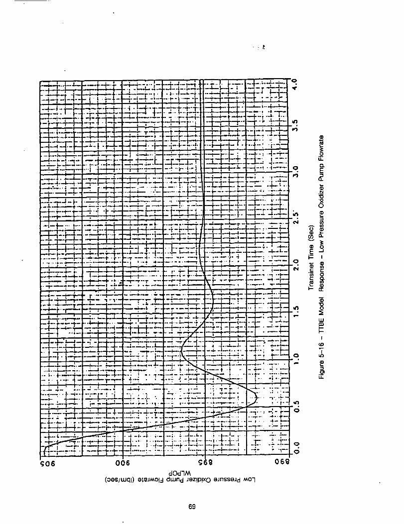
69
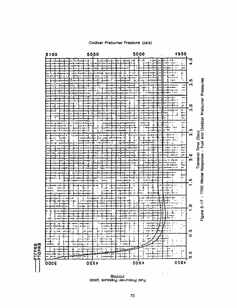
Oxidizer Preburner Pressure (psia)
5100 5050 5000 ¢g50
....... : k" _:.+_-;-- l--f- 4' ++-i- _ t: 2_!-, 4-Ii-- :+--: -. r-
-- - -l-_.--,-- ..i.-J.-..._l-- ....i.--:. .... 4..l _ _ " ='..... . ..... "l" , :___._'-_._--.'-'#'--i-', ...... #...i..-_,-+-- ''m. "'i --_- --l--t-'r---
! i ' • I" • I ,_.., = I .. . = I . i...t - i =, • _ • - J • '....._--_--_-..-_-_---_:4--4--_" _-_ _ ...... 4
---I.-I_i---;-- .-!---_-;-- - =--'i--I"--_, _ .... _. 1 _-Ir- I--+--"-- • --........ -, • ' " --1--4---;--t '___.__r ..,_---_-m-r-..__-:-_- ,__ _.___.._;,-: r-,--.:-,._- _'.;.-..-- 8
_-1-_.'-; -; P ' ; i ; _ .., , , _ ._ '.... _ Q.
, .-i-G-..__-TI-4---_--_-,,-H-- . ._ .-I E
I II _ ! ' - I " _ r..--l.r_ "_ : .. --- t , , :--L -D.,-__ _--G____..1--+;-_-_ '4:_-,-+-_-t_._+_+____-i:; ,-..i
'"r ' _---T-_.' .... i- -i 1-- • F : Y ' :-_ . . , .: - , .... . . . _ ____. • --.- :.;---
.__ .4-'-.t- "__'_'_--TC--"''m'_""-'-"-" ._-'T_'--'---_T_-_-" "I": " : " '•-4" ..... "-"i-'7"'." "r ip,-. • F : :"7 _'", _ ...0
• "_" .... :-r - • i....l-_ .... +--#--; .--- --_'.-# -t- ';" t-._--i-, ---'.: ._ _-_-_
____._----_-,.--t-_-- ._.:j-e-f- -_,_ - _-. _r- cn
, ._, , . , , , , , ,7-± i _ , , .',_.I_' ._..._._.....,.......... i4_-_. _.IU.l;;-_4--_1--_1_--_, _;- ---,-=--E <._<'.
T " l 1 i I . , _ , r ; I i , , rr
4 .'. i----,--." '--i--4--,-, ._.; i .-->_': ";';_ :.... _-r ., _ _.
' _-i_ _" " -_-_I-''--I---_E..... .-.- - "'_', i -;i "4-_4- + .-4. t-_. --:'-":.:."" :- "'__ ....... •. ;._-_'--L_'r ...... m-+-;--_ ..... t--4--i--+-_. : ÷_-f--+- -I,---,-- -i. _7 _,..._....
:"_"-:rl_: -+-:-_-----_; ........-':-_'" }::-."_4_4-_-'-"" -,4-_-=-, ' • .-,_-a-_._....-_-_" t ...... ;-_.-_,-l_ _'_--I_..--1= -.-,-- =----i..f-t-r.-=m__-...... "'-'_- . -
_..._- ,_'- _.i._L',..___.i_;,i;.!.;.:_:..'_=.... _,-, =---: o/ ." .... '- ,t] U.
'--1"'1_""r" ",'_''7"_ _ .... ,_ r'"'ll"'Ir .... ," " ; ...... l--i ./'i _]__" :1"" --_- " I .... l---,i-----,_,,-- --I "-!'_'-'i"- i "
gO= -_" + ! .... _T" Ii.- "" I;" "<.... l-"i _;_--;°'.'1
=== i X.,__] .4 --_--r ..... ;-""-" b .i-_--" --.,- , . i 4-"
<..o ___ _ _..,_._,.... : o_-_- -.' .,_- --_-_- t _...... ; ",-T--_ .... .6
l] 000¢_ 0¢;6_ 006_ O_gt
_kld..-IJ.d(_!sd) eJnsseJd JeuJnqe_d len-I
7O
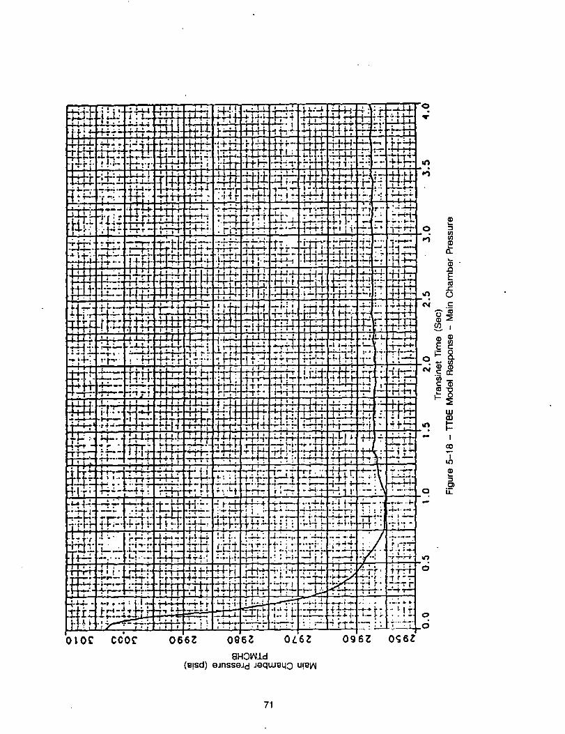
_, ,_+. +-'-,-.+- _._ m+_' +° °*'_'_++"_" - • _ i
+ p :._ ,.,p-,p-..- + , ;.--. +- p , . , , . .+'_
- - .. ....... +-i.i-
+ ........,, .... , ...... ,. .;'_++ _ - + i o iP _,
l I l _ _ _ I . , , ' ' + : ' rill + . .
-.r-n--,:-::I::_-': .+.-,.,-.,,...,---'r,-.,'--,i ;';,.:.'--"+"' r_FP :'T4_..+":+++'PI'r'''t"rff'_'.+"+-''++-+_+'+"++__ .,'F._:-.,+-H...--i':+?...,..+_
F"-""" ,- _ "++]:,.: o- -J. i.. = • ' ' " " • " " ' ' ' " " _ " ..i...-..-,
OLO£ C0'0¢ 066Z Og6Z OL6Z Og6Z Og6Z
BHOI_£d(_!sd) eJnsseJd JeqLu_qo U!el_
71
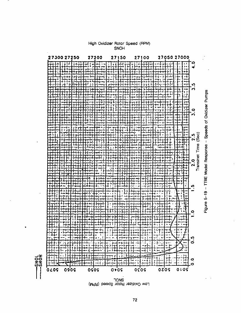
High Oxidizer Rotor Speed (RPM)SNOH
27500 27250!
5O
"IONS(IAId_l) peeds Jo_,oEIJez!P!xO _o-I
(}
f_Q.
E
0.
O .N"13
,.-; "RO
"6
e; co
'qe _I- 0
UJ
t
T
.D
d
0
0
72
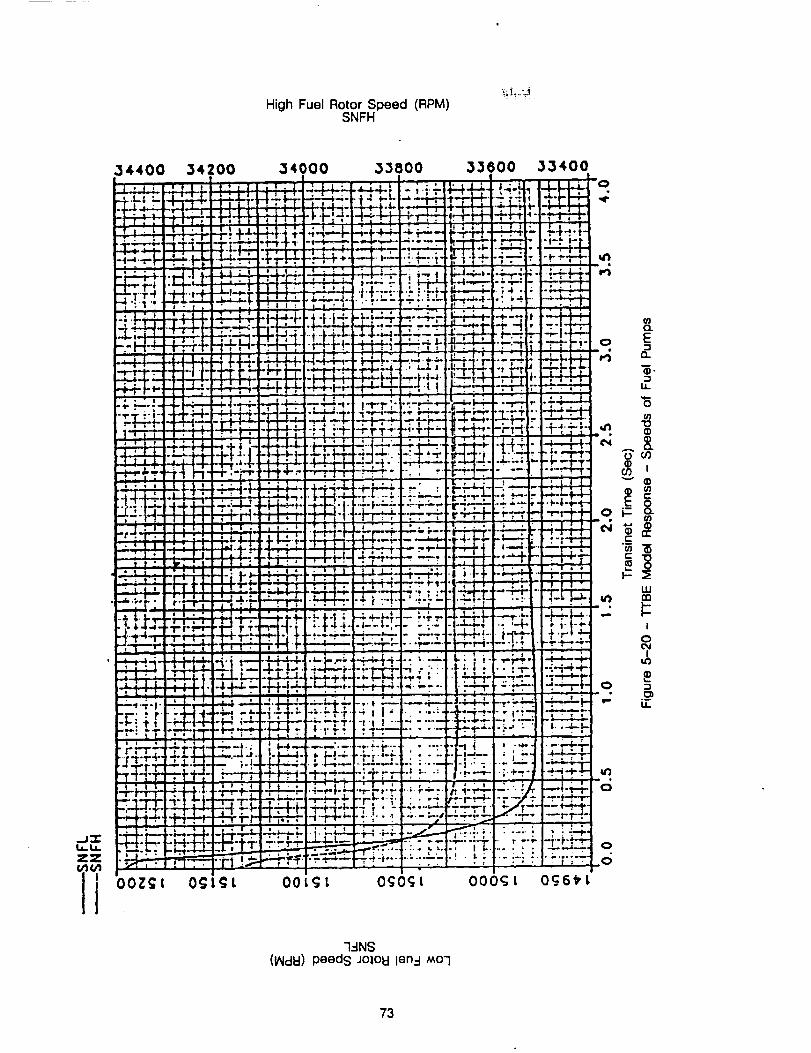
High Fuel Rotor Speed (RPM)SNFH
..J:z:ij. 1,_zzl+i
.34000 ,33000
_-L4.._J ....... ".-',.+ i,,
. .
: r't-i-'_-IL't'Y.-_- +r-'-_-_i I
• -I- q" I
7
i* I
._-
• ."
I t *
.°
_.:.._._.
"1-4-.;.,;r..--:
O0
I ' ',-• . i
•...++T
I " 1
• .-p. -f--_
_ ._..
•, ?.:-:
lil
o
o
6O_6_t
G-INS(I/MdEI)peeds Jolol::llen-I MOG
73
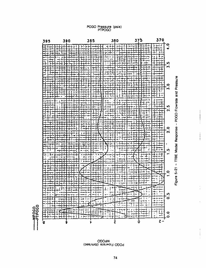
POGO Pressure (psia)PTPOGO
t01¢b,Oa
i'
3g5
!
__ L I
-I-,_-' ',
3go ,385 380 37,15 370
i-._ " _._ i' le:.Li ; _ G _ . ' _ -44.1- -,._,LI 'k;-l'i'i "'_'-,'I"' ' " ="_"=
"''_ "i""_" ._, "r" - - ' "
=.L _ -._--:--,-__-.-..-__k;_" _-"' " ..... _ l::_i±:l_:_ i i:__:_t- , - i "_-l'""'.-'. I i._L--i-i-_ .'___.i4÷,-_-+-. ,,-_--_-__+ _" _+_--'L_ , • /! t i I i- .
........ " " _: " ' _ _t-,l-_-I-l_--;-i-I ,_" i i _" '_t' i ._-f-_"l-t'_--i-t" !:_[, rli! I
" "; " =-- " ' . I • t I _ I I I : il,
. - ,, _---_.,1:1__;L-. r'_',"'"-'-+-'--'--+-'-"r : .+..kt.Y.i_ k H _
_ ; . ._. _.-I' • ........... - - : i i a : I I " _. ._l,1
_-"-' .......... -. j__i;L-.___" ' ,','=_=..T_-. _-_."_-, i'r'_-';':' ..... ._:T .........j.l.4_i._ I_... LJ-I.'_E ; +.---_._ t .- ...... t-_÷ "+ l-t,! ,__1
" ' : -- _ ' " - " --:: '_ , " " L-...i.lJ _.-l----,-I
_7 ..... -_x_,_..,---: ;_;-'i- _..+" ri--'.--_-..:i.:-:'.--!_-,i ,_.. ,ii ,!'!! I
": :.. i . ".... : - -;_--;:_- ..... _-!-.'-_!-. .... (_3Tj. ...... :_ ......_.-,_ -t-,...'-,..- --t.-_./i ,I -,-61-.i- t-..I-4-; f-!-.-4-_-• - - • • • ;-.l. " !-__ ,--.i-_:'"""'. T'T .r'N. r? , , 1"" , _ , :_l_ .,-,.. .... : ; _i ; ". 7!-,_i_'l'_,'L __:.....
.. . ___' = ,.- . i
....... , +_L_'i.-.; ,_;. • ', _-_ •, .r_,j-.;-__,;:-_-, _--4;-_-! ' _'+_-_'T_'"-+.:i:_.__- -,-;-._-, --
" ;" _-_" " _ ' " _j.4 i-__,...... ._"-"-_ "-I_.'I" ,_ , . i i "',x ,.,"_'_ "_T, ,_--;-'_--'T. 1 -r it, "_ .• "T" H-+_+ _-'; ....... ' - i-_.-'r'l _.I ;- _ ""- _ ..... .__ ._-_- _-'--+""_" I. "/ ,.- ° ,n
" :j4x.-..___ " _ "_i-._.i.l..j. _'_ i _. ,...,___.-_.__ --- ' '" t_- "-'t'"r. •...... _.._ .- ..,-.,-.,"" "---'"_ "-'.7-r_,"""-'"." ".' . --___-..- ..--'t-,-t-r_.--,-.,-" --_ ..... -_ " _, t--- ._...... ;. _._ _-!---_17_''_'1
"_.I"I_1 i ] I "G ;_-i i ", l-'l_-
.... .i.._ ....... -_ .._i-_ l-_--_ i-r_-,--_-,-_-_ -- .... -_- , ,, .. ;#.!..__t._._!_.kl"_-_-'-" _ " "" ._,-! _-_-, ; i --+--_+-_: !
"_"-'-'_ _ _ i "-r .... "i"_'-'-. ", "l'-i-t'--_ i-;- ' ' ' " " ""-.,.l " : . '-_ _ 'i . : _3.'_-,--,-,.+_.-_-, .......
- .. __.,-_-_---.. I..-_.-. ;_._--7. !'..,_,_, ; ..._:_ :.-_ •..... , ,., ..,__..... _,__+.,.__._.V_.;.d -rrT,. ---r.'m -_._'_• ;" ; _'!! ,. • .. . ';_ , ., - __
i l ! _''_ "@_"' .... + "--_ ........ _" " _' _- v'l._ i -' :" "_''< _ i_ " "7_:' ' J-" -_:_-_-" :-.-I ._"; .._,_. •......, ......,.... . I-;.T-.T--.o
......."'_' "E_ I.--.._._-.--,-.., _ ! • _ .....b-;-÷._- ." '.' ......."--! .'-t- 7;'_-';'-- !,'-1'.--r4 -:H-.-_" "" ' , _ .
_ _'l-i" :_ _'1 '_-,'-" l, "-.- o'--_-'-- :_, _;" it; -: 6. , "-t "+T _ .-_,,-.-]-'_-_-"'rT!
Ig 9 t Z 0 _;-
¢/)
O.
"I0t-
O
LL
0(9
2I
0gr"0(3.o3(grr
130
LU
I
II.¢)
3
LI.
OIDOd_(oes/LUql) elg.l,'_Ol.-I O'-OOd
74
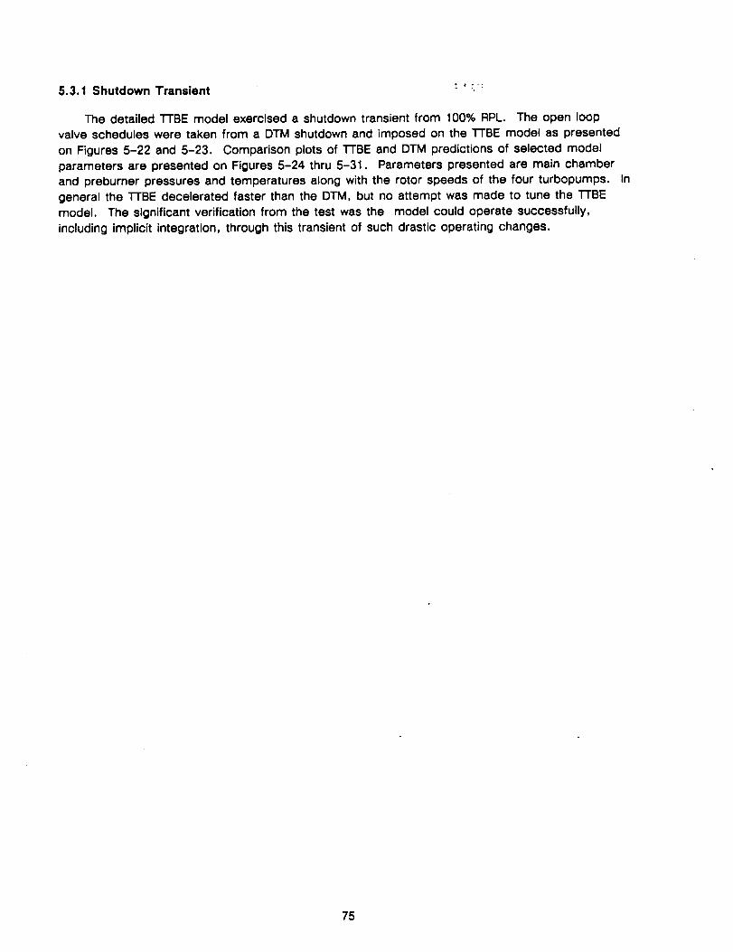
5.3.1 Shutdown Transient " __;
The detailed "I-rBE model exercised a shutdown transient from 100% RPL. The open loopvalve schedules were taken from a DTM shutdown and imposed on the TTBE model as presented
on Figures 5-22 and 5-23. Comparison plots of TTBE and DTM predictions of selected model
parameters are presented on Figures 5-24 thru 5-31. Parameters presented are main chamberand preburner pressures and temperatures along with the rotor speeds of the four turbopumps. Ingeneral the TTBE decelerated faster than the DTM, but no attempt was made to tune the TTBEmodel. The significant verification from the test was the model could operate successfully,including implicit integration, through this transient of such drastic operating changes.
75
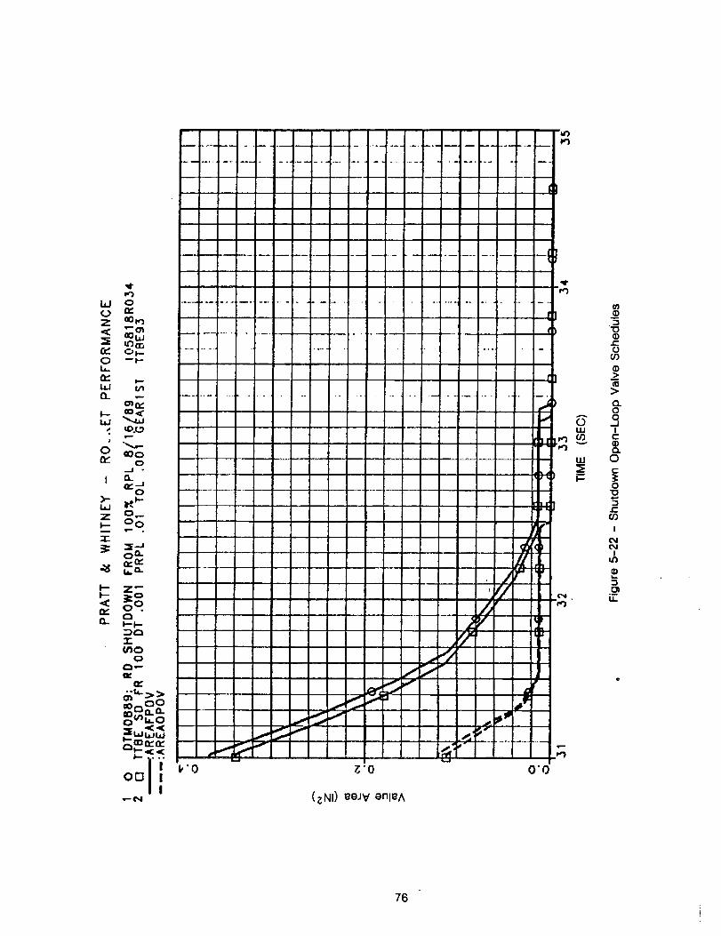
0
Z a3_
rr" Ot--0 --l--U-
twI.'-
o_
p. tO.¢._
0 e0oty-
ro
"'I ..........
I
r
........ I ......
C
s
If
_L
,q.
z o ,I/
I_ Ill
._qf
___ . _" _.; ._,_'
O0 1 ! I,'0 g'O 0"0
_e_ (_NI) _eJV enl_A
A
0ILl
UJ
I--
0
"100
oO9
_>
>CL00
._1I
g..0=.-,0t-
O"o
e-CO
I
I
.__
76

77
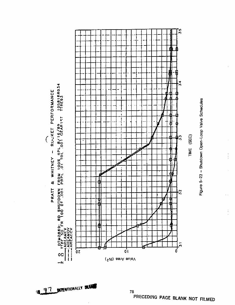
W O
Z eO_
re" o_
n. i-
_ O:Q:
L_v _¢2
_C
.j •
0
Z 0_
0n.er
_ ,.o.
oq
dLL,il.'L.u
_<._<.
O-Jl,III
,,,.._
O7, O|
(_NI) eeJV enl_A
¢)t=,rOOr)
_>
>
o.0
•"" or,b _juJ Ir./) _-
LU C)
0
r"09
I
(,,,)
I
LI=
78
PRECEDING PAGE BLANK NOT FILMED
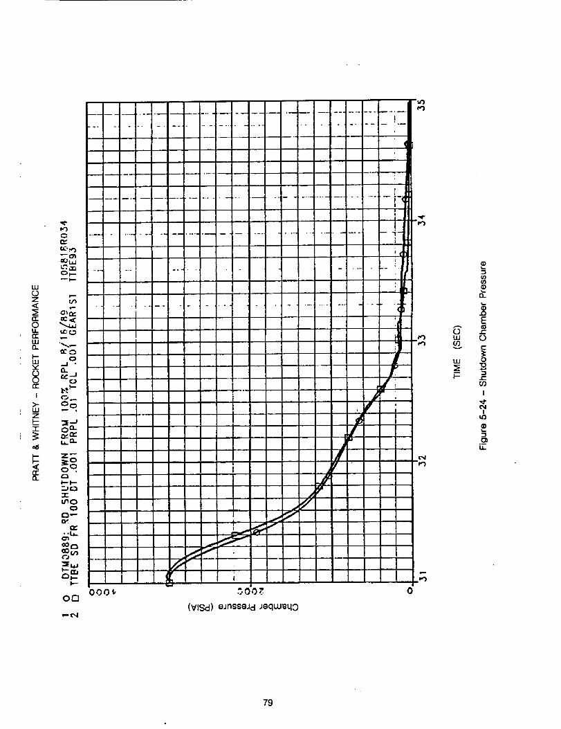
w0Z
n-Oiin"w
I--w',,F00n,-
i
>...iiizi-7-
,,:1:rrn
I
° t'
m,
m "'1
L"_.;,.r,Or--
i,,,,,-,
r3_
0.j •
II
I _,
....... t• '1 ..... i ......... 1I
1I
I
I-- :"7 ::l---F-i.--:l
I||
!-1_lll+
3o °, I
0
{3,--oK
:dI
!
000_, ._ 0 0,.'. 0O0
(VlSd) eJnsseJd Jeqwe40,-- ¢',1
0wO0
w
I-
-!t_
t_
E
0E
0
O0
I
3
U..
79
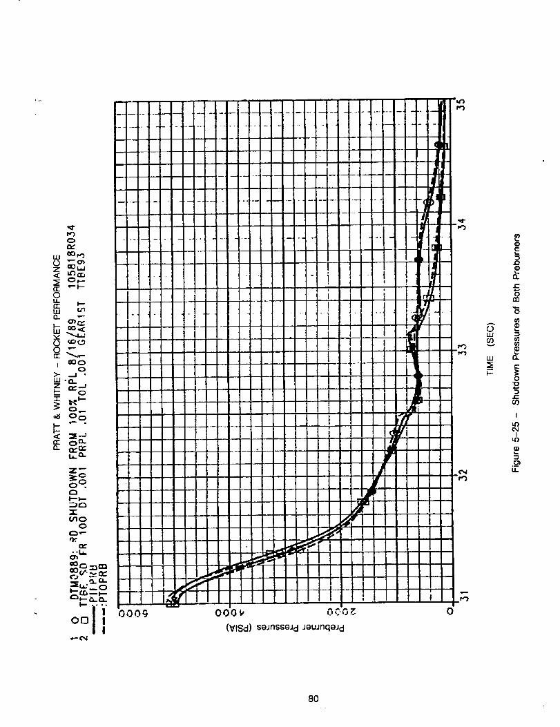
I*")
w ¢10_
Oz--__) I.,JL_') n--,
_< O,--rr ,'- i,--Ou_rr _--wO_
w
0 ""
I ..j_
7-
0,,--_ 0 o
n
L,i.. 0-
"IX
7-, ff.J_--_--
O0
,,.- c'q
O00V OCO_
(VlSd) se_nsseJdJewnqeJd
O
A
Ow00v
w
h.--
G)E
n
r,-
rn
if)
01
n
r'-
O"O
0')
I
I.n¢N
Iu_
LI..
8O
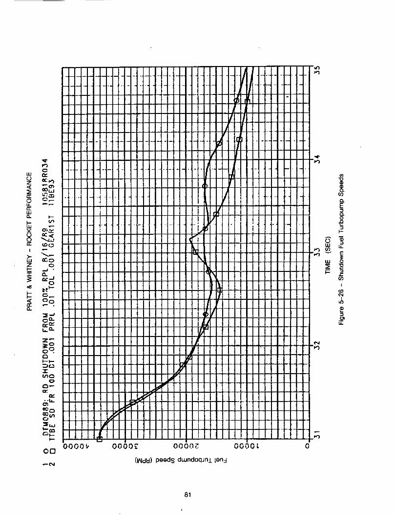
0 _e,)z,< "-"o'J
rr g. :T-,0 O,--
¢rU.I
_ 03 _o -_
z _-
e_ o
_: °o
i_a:::.(1.
o o.
_u.
W..cn
01-1
--1",4
0000_ 0000_ 0000_
peedsdwndoqmllenB
O000L 0
"o(D_DO.
CO
O.EDO.0
I--
I11 U.O_
,,, o_t-
OO
I
cJDC,4
I
.__u.
81
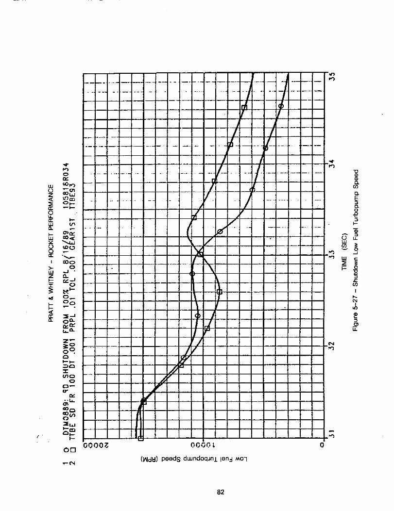
m
: ,i_!/,_..... kii- 4-. ....... ij/
.........
0 0" 7 -- : :'
laO_ - . !
_. - x,,
lJ'l I_ -, ,
C:_,- V
U"e_
"_bJ
O0
f;d
r_
0000_
..m
O00C..,L
.,-oN(IAId_) peeds dLundoq.Jn.Llen=l MO'I
0
i--)
',W"
.,,,'3
'1o
Q.O3
czE
o
I--
0 u.LLI
v 0_1
LLI ¢-"
'1045U')
I
I
,m
LL
82
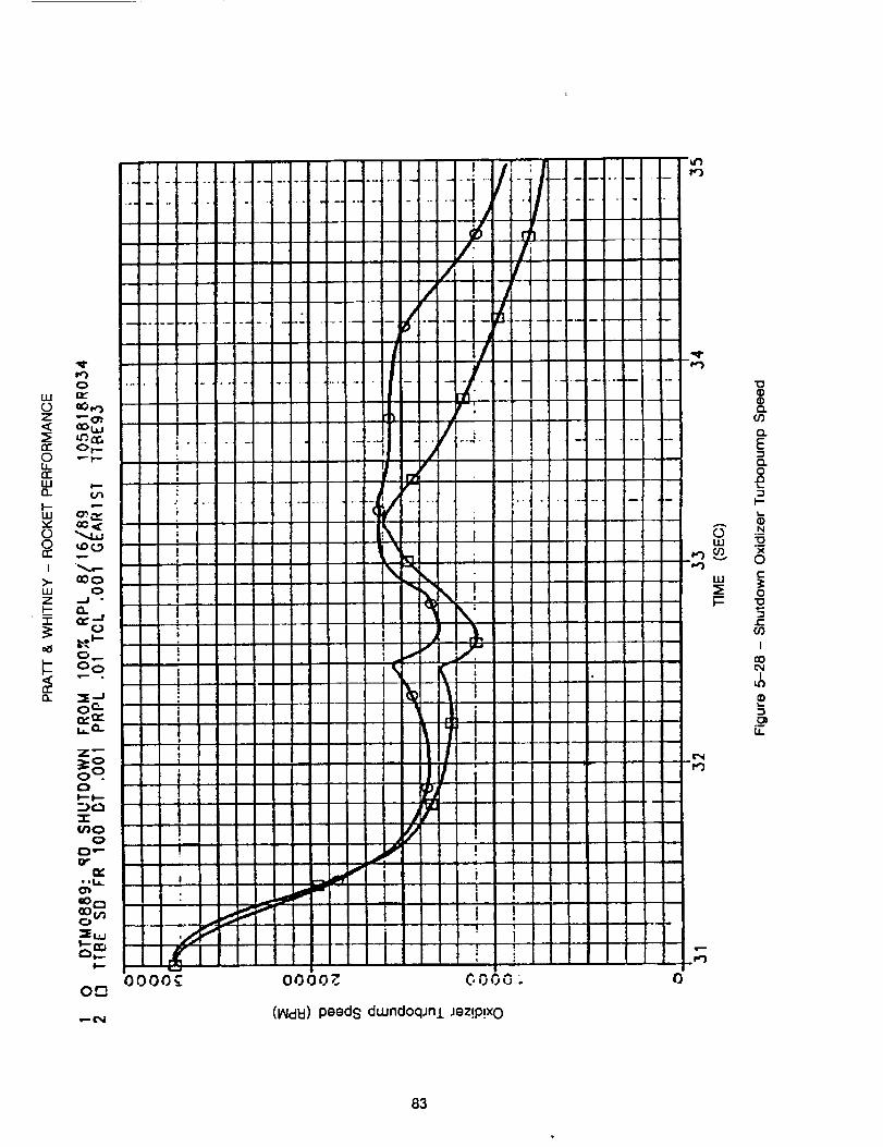
0w
0_.-0 -'- _--U-II
O. o'_
0 to C.._
..j •
z _'-,
_ Oo
n,"O.. "_-J
O" r,je
I,=-
oo0000_ O000Z OOO0
(_d_)peedsdwndoqjnlJez!P!X0
0
"o
cPO.Or]
CL
E
O
I-
N
X
or=
O"o
cO
I
coo_I
i.o
I,IL.
83
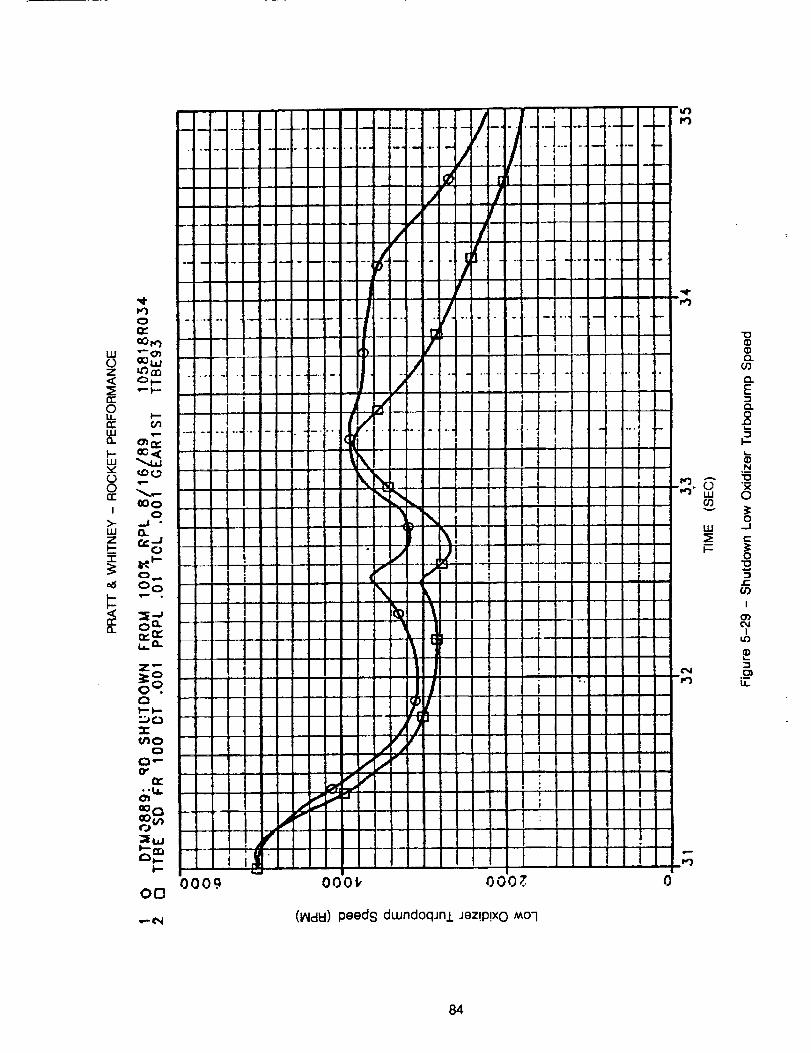
_I,LI
z _,_Ol--
_r_
50n-
OO0I 0
_- ..J -LU O.
_ o
0I..- I--
0
0
"_LJ
I--
oo
.,-(N
0009 000_ o00_
(_d_)peedsdwnd0qJnlJez!P!xO MO7
0
OwO9
w
I--
70Q
o.or)
O.Eo.o
I-
N70
O
0_J
_-.3:0
Or)
I
o)c_I
_o
.__Ii
84
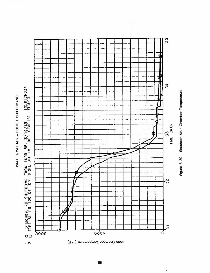
GO7,,.,
00...
o _zU-G:W0. _--
.
_evi.n
o _.
-'1-
qy
(,...,_v
O.'7
•,-- o,I
000_ 0
EE)
I--
Et-
O
c-
o"o
I
o
Ii.o
11
85
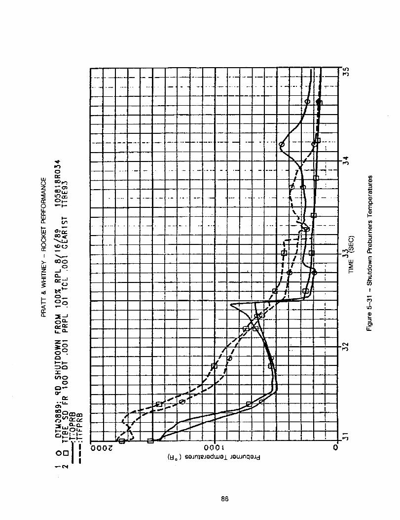
---_4
0
A
oLU
tl)
q)CLE
b-
E
.o
o.
e-
o
t-oo
i
o_i
im
86
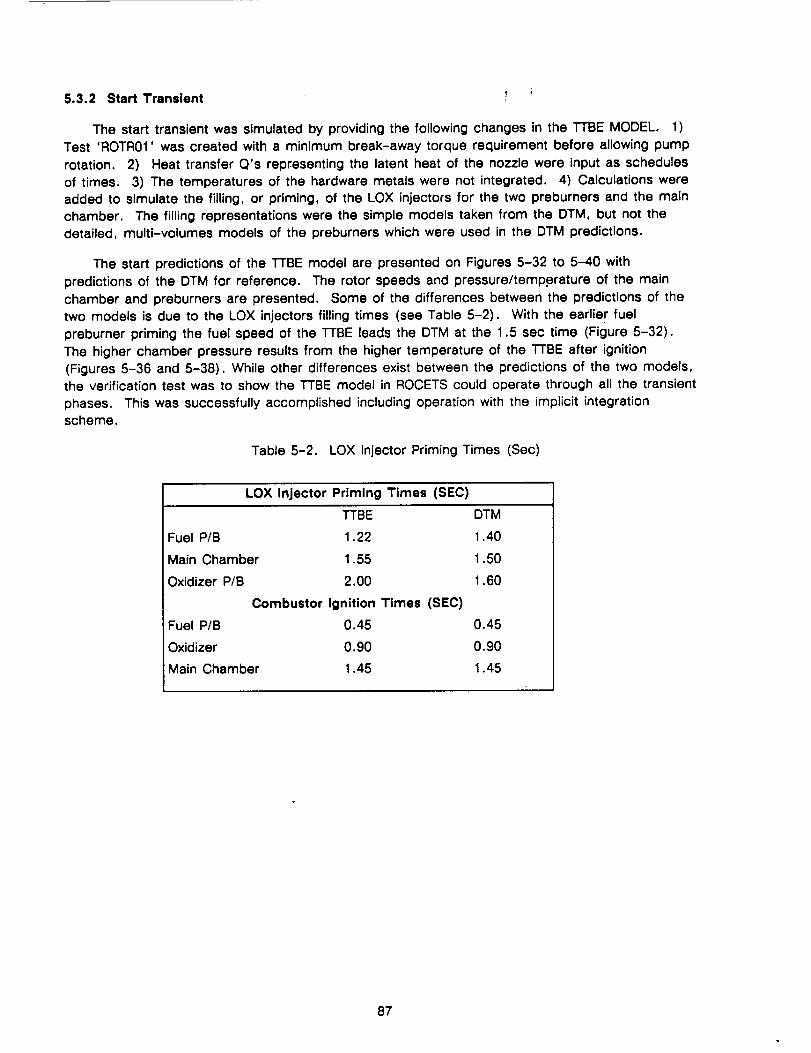
5.3.2 Start Transient ; ;
The start transient was simulated by providing the following changes in the TTBE MODEL. 1)
Test 'ROTR01' was created with a minimum break-away torque requirement before allowing pump
rotation. 2) Heat transfer Q's representing the latent heat of the nozzle were input as schedules
of times. 3) The temperatures of the hardware metals were not integrated. 4) Calculations were
added to simulate the filling, or priming, of the LOX injectors for the two preburners and the main
chamber. The filling representations were the simple models taken from the DTM, but not the
detailed, multi-volumes models of the preburners which were used in the DTM predictions.
The start predictions of the TTBE model are presented on Figures 5-32 to 5-40 with
predictions of the DTM for reference. The rotor speeds and pressure/temp.erature of the main
chamber and preburners are presented. Some of the differences between the predictions of the
two models is due to the LOX injectors filling times (see Table 5-2). With the earlier fuel
preburner priming the fuel speed of the TTBE leads the DTM at the 1.5 sec time (Figure 5-32).
The higher chamber pressure results from the higher temperature of the TTBE after ignition
(Figures 5-36 and 5-38). While other differences exist between the predictions of the two models,
the verification test was to show the TTBE model in ROCETS could operate through all the transient
phases. This was successfully accomplished including operation with the implicit integration
scheme.
Table 5-2. LOX Injector Priming Times (Sec)
LOX Injector Priming Times (SEC)
TTBE
Fuel P/B 1.22
Main Chamber 1.55
Oxidizer P/B 2.00
Combustor Ignition
Fuel P/B 0.45
Oxidizer 0.90
Main Chamber 1.45
Times (SEC)
DTM
1.40
1.50
1.60
0.45
0.90
1.45
87
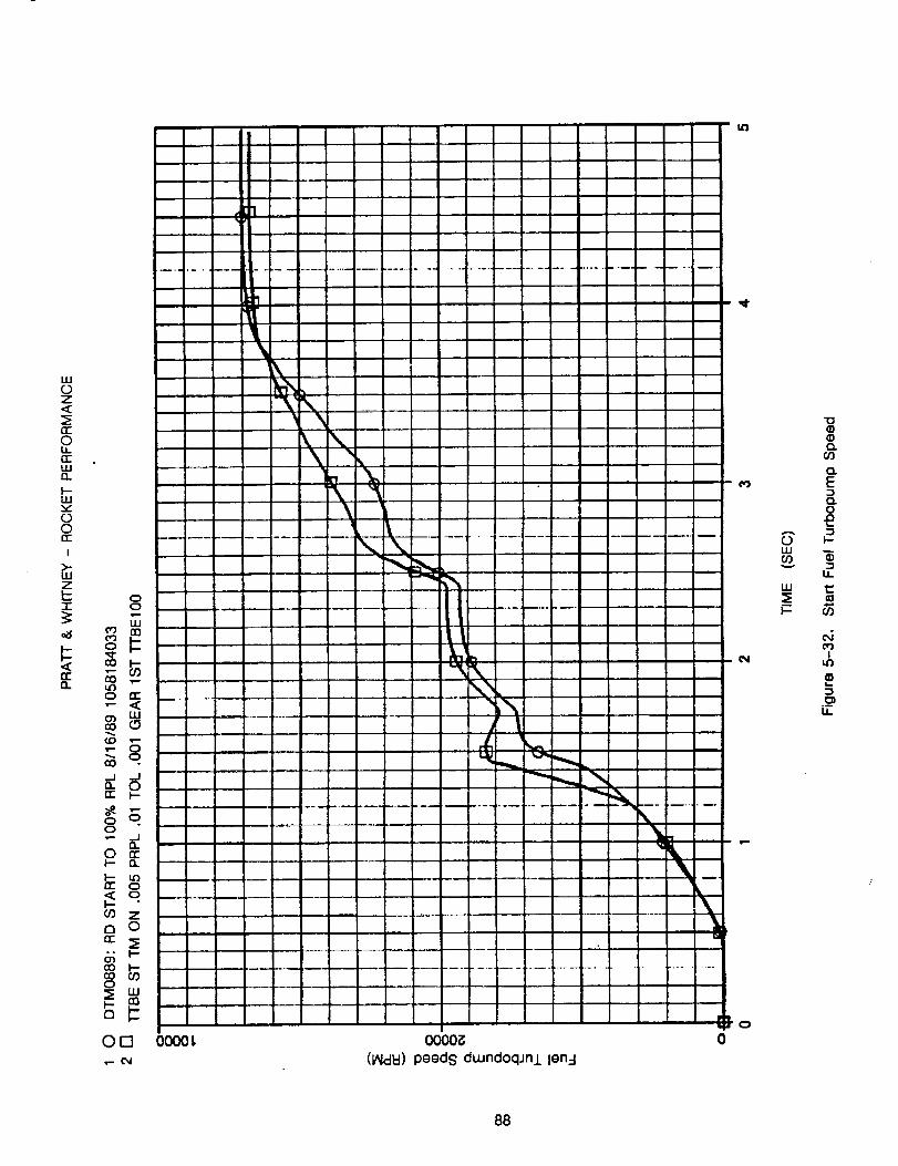
LUc)Z
n-
Ou_0cILl13.
F-LU
C.I0cc
I
>-LUZI--
"l-
n,"13.
00
o_j0
cO
0 n-
cO
cO •
_I -J13.
o
0I-- 13.
I.- tc)rt" 0,,_ o
Z
a 0
cO I--co O_0
i-
Orn•r.- C_i
L\
"N'\
\\
\
M
\\ k
\
m
L
\\,"h'_i', |
I
k
%
O01_t 0000_
(IAldld}peeds dLundoqJn.l,len_-I
|
0o
0LUO0
nun
'*0
(Z)
O.
EO.0
I--
ii
I:::e,=*
GO
t_I
ii
88
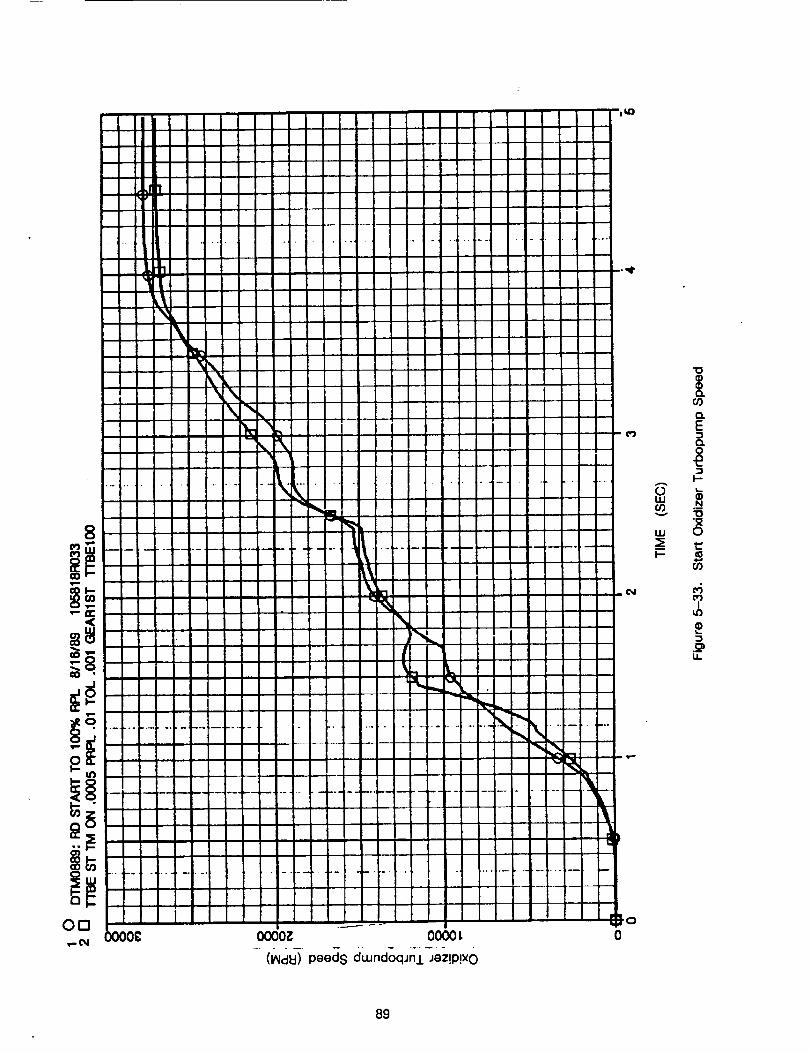
O000i_ 0000 L
-(l_c_ peeds dwndoqJnj.-Jez!p!x0
W
CO
o.
E
O.
I-
N
I
U.
89
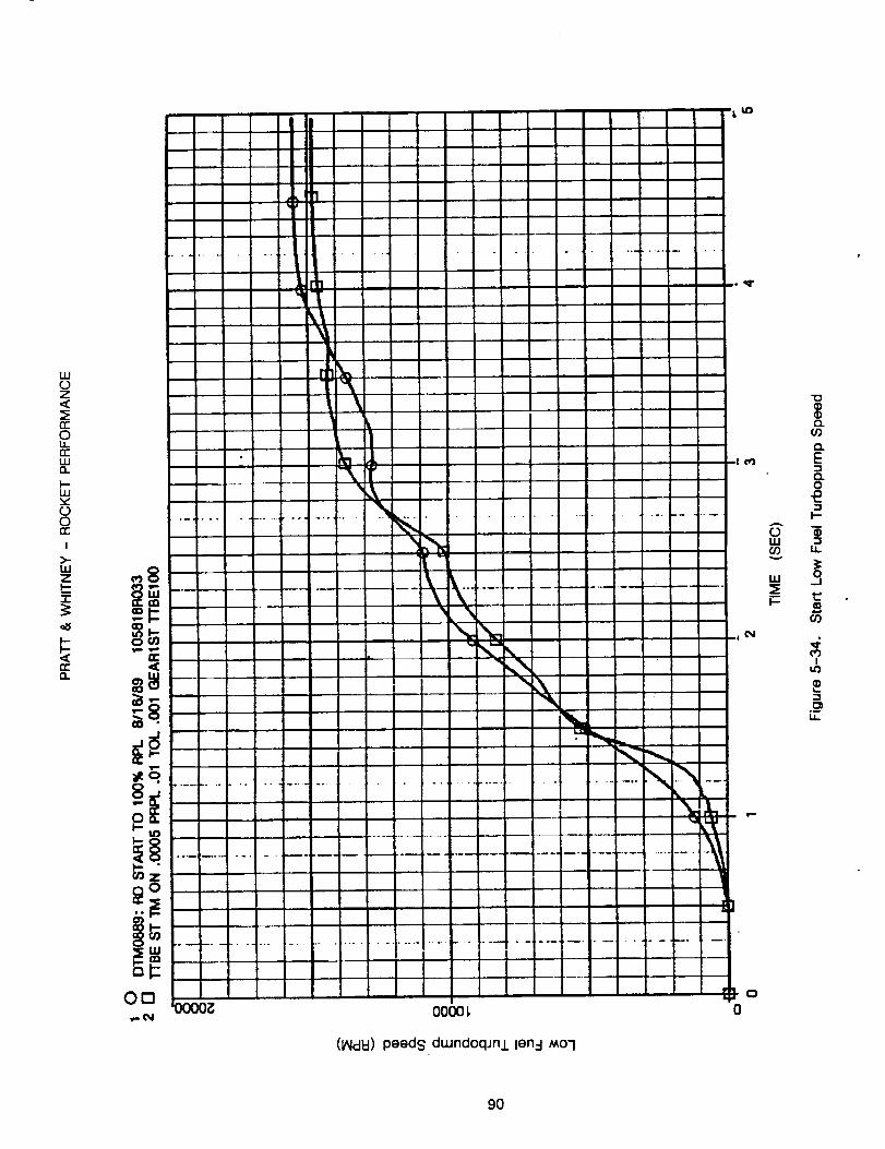
1110Z
n-OL,L.n'-iiift.
I--ILl
o0h-
i
>-
zI.--l-
n-.
°.
1 r!
"l
_o
°ip,
..... jo
'll
000o
(IAIdkl) peeds du,Jndoqjni len:l MO1
o_
O
0
A
OILl
v
LLI
Q.O0
O.E..nC_LO
_=
I--
Ii
3
CO
I
-,s
u.
9O
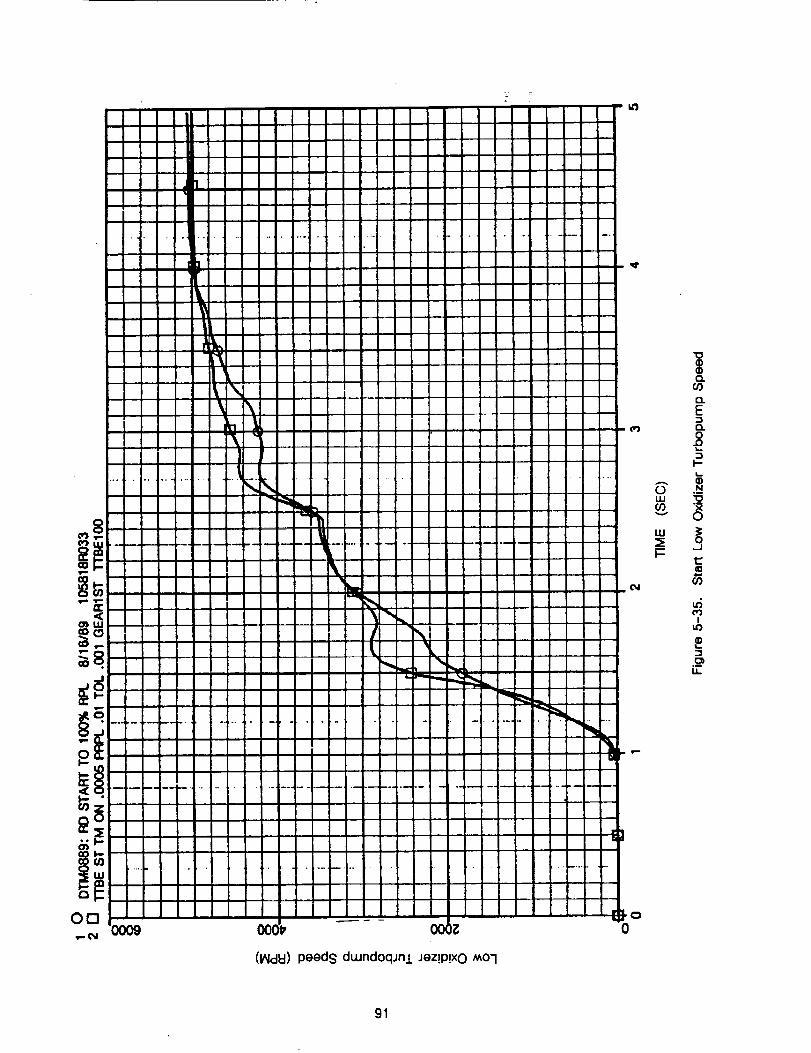
(I_IclEI)peeds dwnd0qJnl Jez!P!X0 Mo7
AOIII
W
"O
O.
{3.
E
3
N
9
c/)
IU_
.oii
91
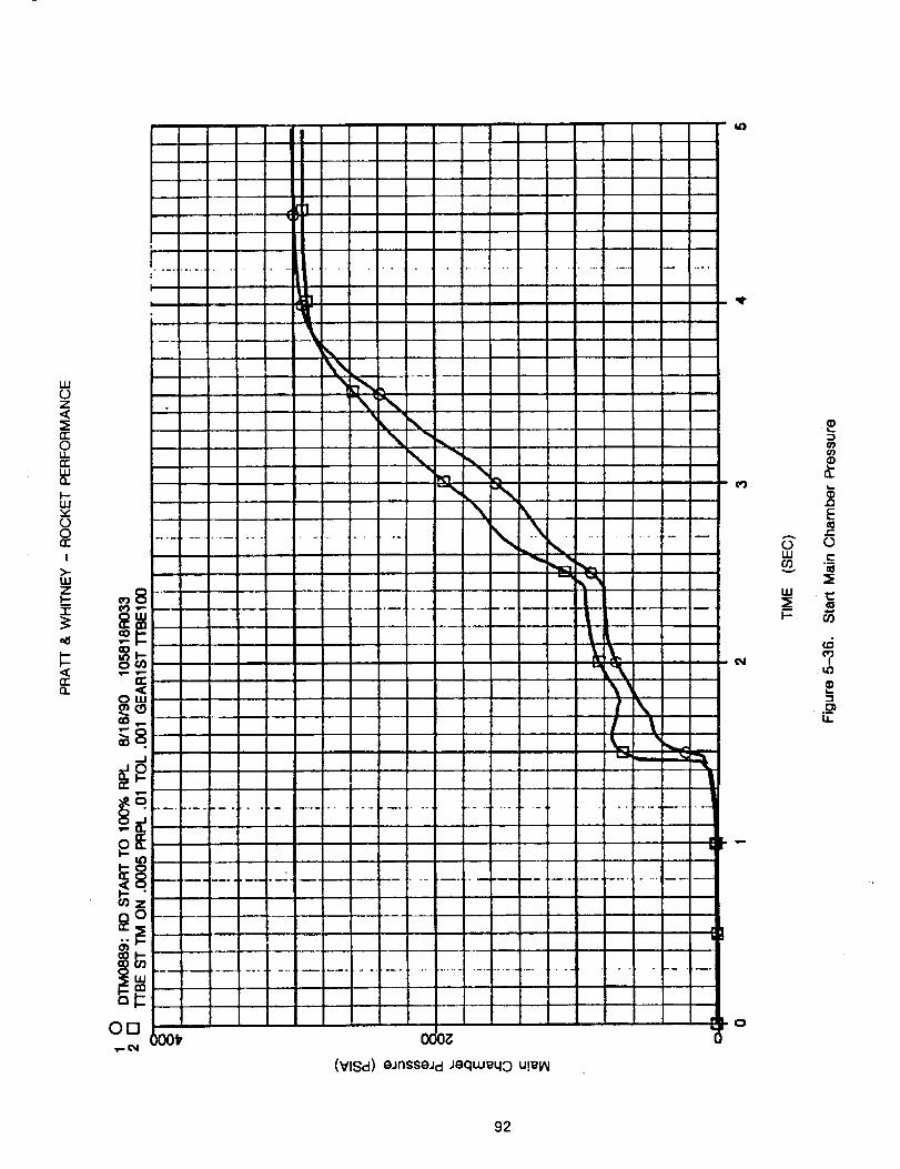
uJ0Z<
n-OLLrrILln
U.Iv"00h-
I
>-uJZI--?
rrn
i
1
-P ...........
........
(VlSd) eJnsseJd Joqu.Jeq0 u!_I/_l
Oil 0
0mlm(I)v
lira
I'--
E
0
(,r)i
I,i,.
92
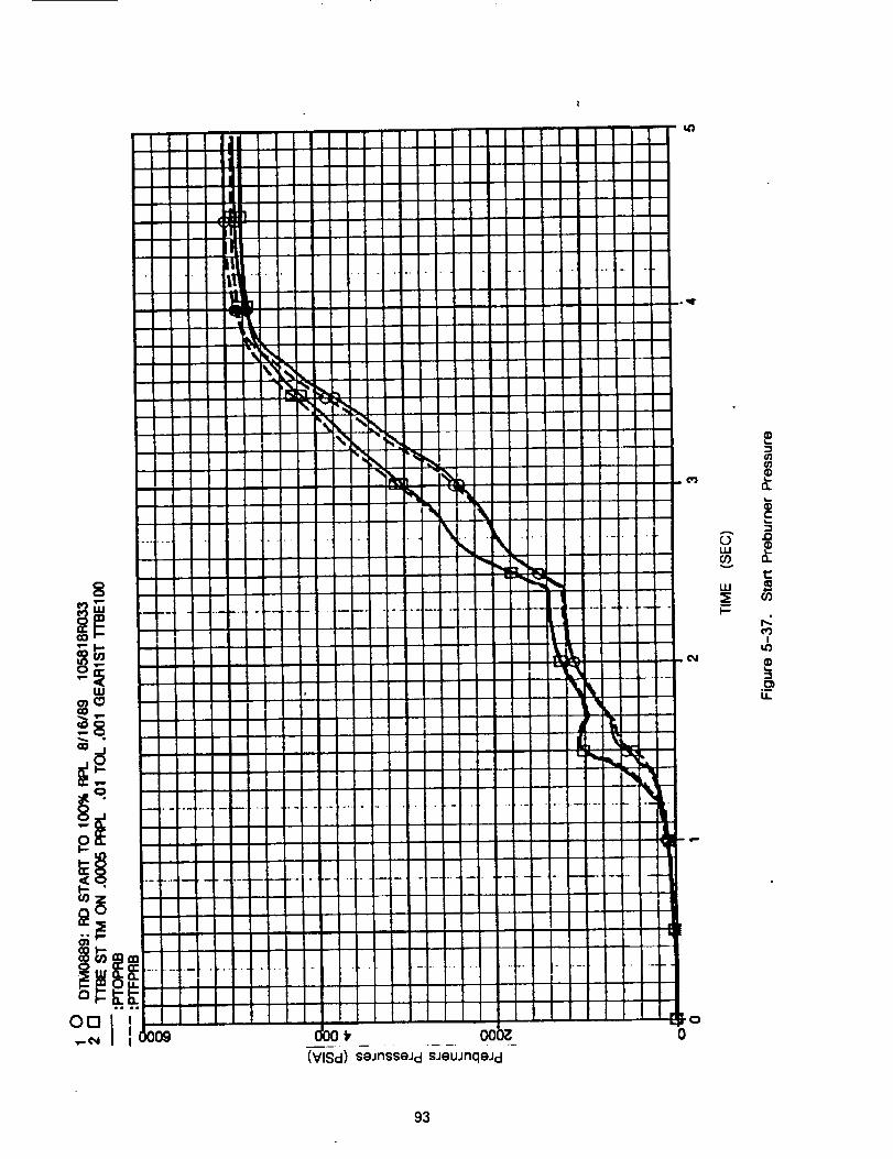
A
0ILl
v
LLI
I--
@'j@'j
E.=,i.0
t,.:
I
u.
93
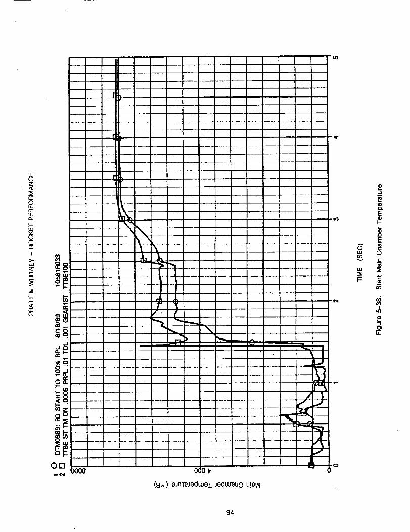
I"#
w0Z
0c:0
ccwo.l-wv000c
I>-wzl-I
e_
I ,"
6_
, i r,li_r , i : i
.......• ; : : L ! i " " , _i '
.................... ,......... ................ ,.......... " ..... ........ 7_
Oa . I i '_' .o
(_o) oJrlll_JgdW@J. JequJ_qO U!_I_
A
0w
w
I-
o.E
l-
rlE10r-
0
0_I
i,o
o3
LI-
94
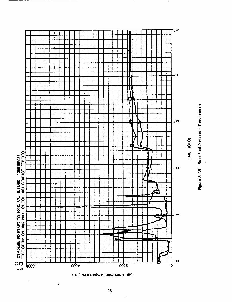
I,-, 1,-
nr
OEI
(I::Io)eJnleJedwel JeuJnqeJd len:l
0W(I)
w
I--
3
8.E
I--
F.=I..0
LI=
c4
IL¢)
3
ii
95
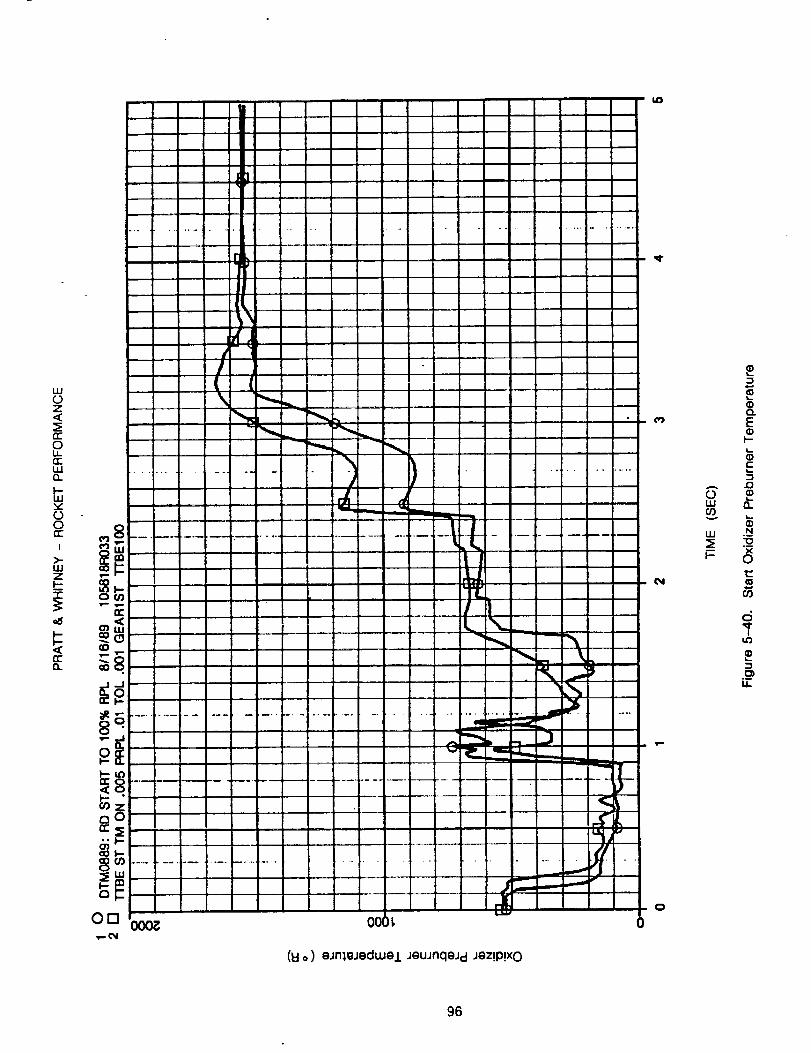
J]
uJOZ
rrOLLnr-iiin
1--111vOOE:
I
>-ILlZI--"1"
n"n
i ..................
[k
r
E,
Iv"
i1.1
On ooo_
I
"l"C!L
i...... jm - _... ..q
IN._
_....._,-,-..
°
U,,_ J
°" L_.d_ _
_W r
(8 o) eJn},eJedWe/JeUJflqeJ d Jez!P!X0
0
OLU09
III
I'-
O
E
I-
E:3
.D
13.
N
OI::
Q
ii
96
5.3.3 Closed-Loop With Control
A NASA-MSFC control Model was interfaced in the ROCETS system (Appendix C) and used forclosed-loop operation with the T'I'BE Model. Figures 5-41 through 5-44 present results for athrottle transient from 100% power to 65% power and back to 100% power. Parameters shown are
chamber pressure, mixture ratio, and the four rotor speeds.
5.4 SUB-SET MODEL GENERATION TEST
To verify the generation of the linear model partials, a linear, sub-set model of the detailedTTBE model was created. Then the linear model time domain response was compared to thenon-linear model predictions.
The detailed "r-I'BEmodel had 122 states and 14 algebraic balances. Of the 122 states, 60
are using iteration parameters other than the states (i.e., 30 volumes are using pressure andenthalpy as the iteration variables to close the density and internal energy corrector equations).To reduce the linear model order to a manageable size for the verification test of the new partialgeneration technique, all states were set to be driven to their steady-state values except for thefour rotor speeds. Thus, of the 136 TTBE simulation equations, 132 were analytically eliminated
leaving a 4 state model.
The linear model was generated at 100% RPL with a 0.1% perturbation size. The oxidizerpreburner oxidizer valve area was used as the model input, and pressure at the low pressure fuelpump discharge was the model output. Time domain results were obtained using approximately a1.25% step on valve area by first generating transfer functions from the linear model matrices andperforming an inverse Laplace transform.
The non-linear model was executed using the same constraints (i.e., all states forced tosteady-state except for the four rotor speeds) for comparison to the linear model results. Itshould be noted that a steady-state balance was not performed prior to initiating the timetransient, so some initial drift is observed.
Figures 5-45 through 5-48 present comparisons of the linear model to the non-linear model.Excellent agreement is observed, especially considering that the time response has an order ofmagnitude larger step than the perturbation size used to generate the partials.
The excellent agreement is verification of the linear model generation method, it involves achange-of-variables for 60 states and analytically eliminating the 14 algebraic balances and the118 states which were set to steady-state. The partial generation technique provides a powerfultool for performing linear analysis and generation of reduced-order models.
97
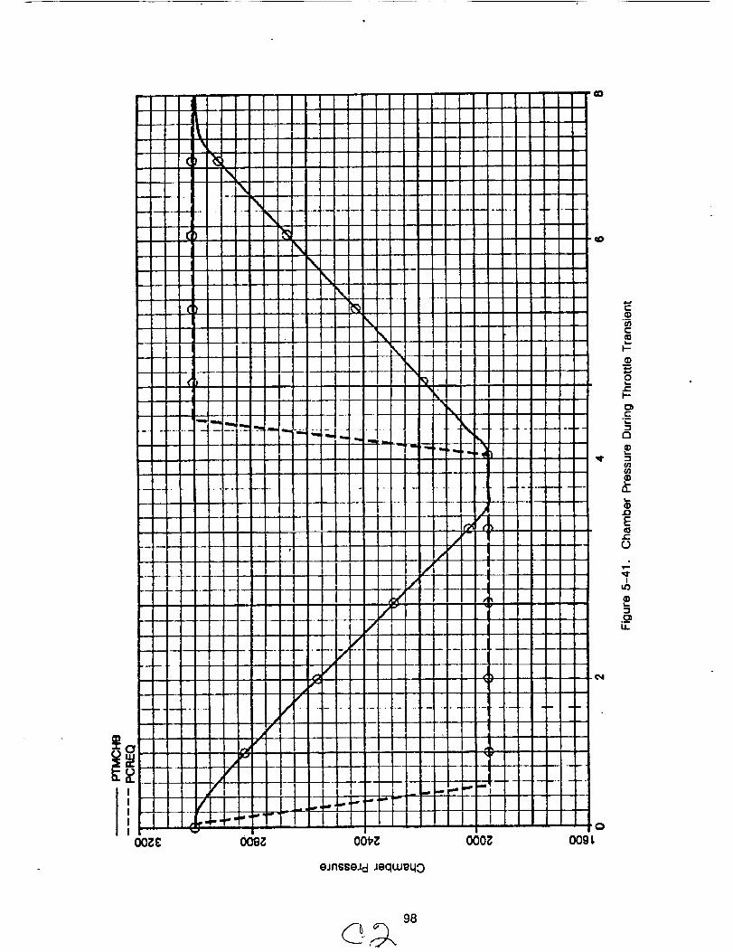
iO00Z
98
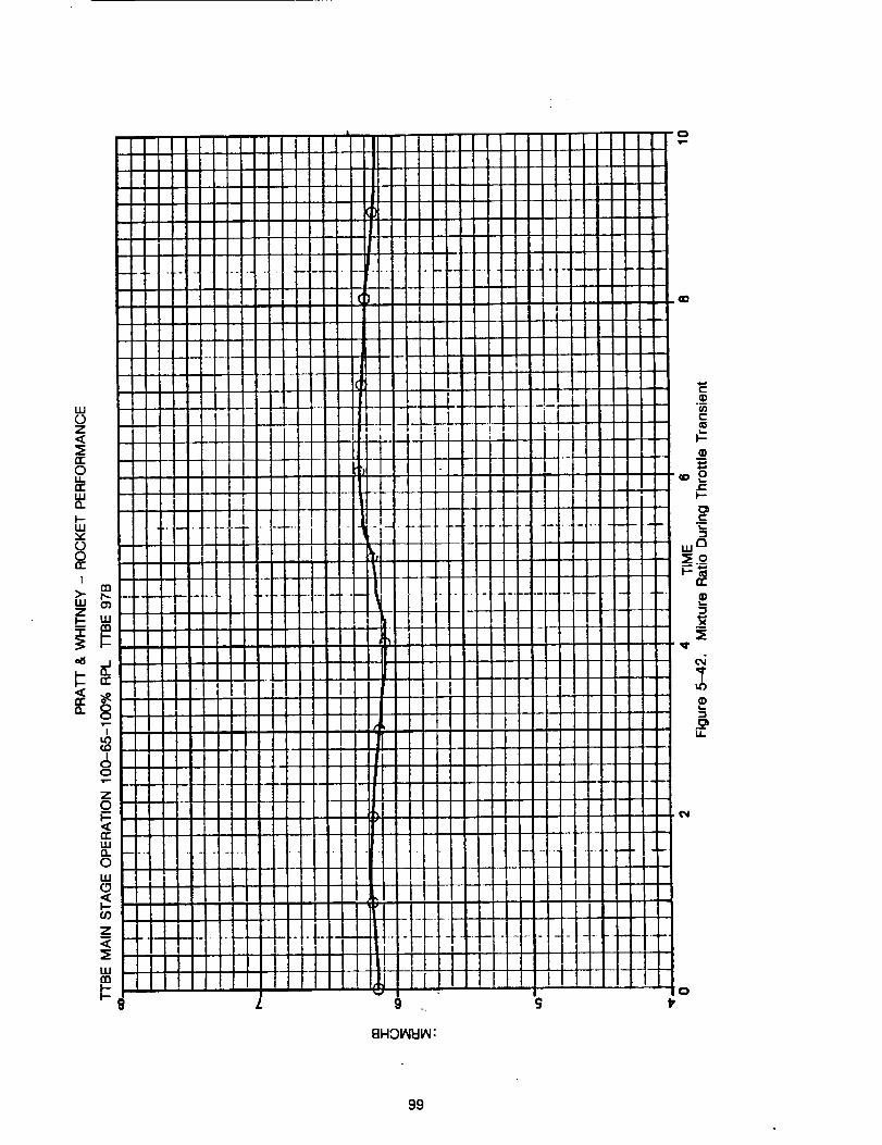
w0Z
0U_n"W
I--W
8I
w o_
I
I
8Z
oI,-
wn0w
Z
w
8FIOI_II/_:
8g
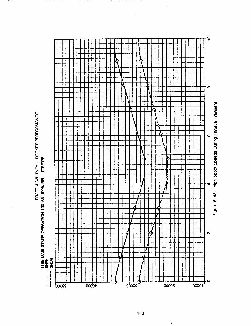
LU0Z<
0u.n"tU(I.
uJ
(3OCC m
!
Z
uJc_
¢0
Z
100
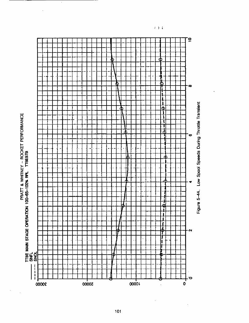
o.
1
,>,,
Q.
|
IO000C 0000_ CX300L 0
O
101
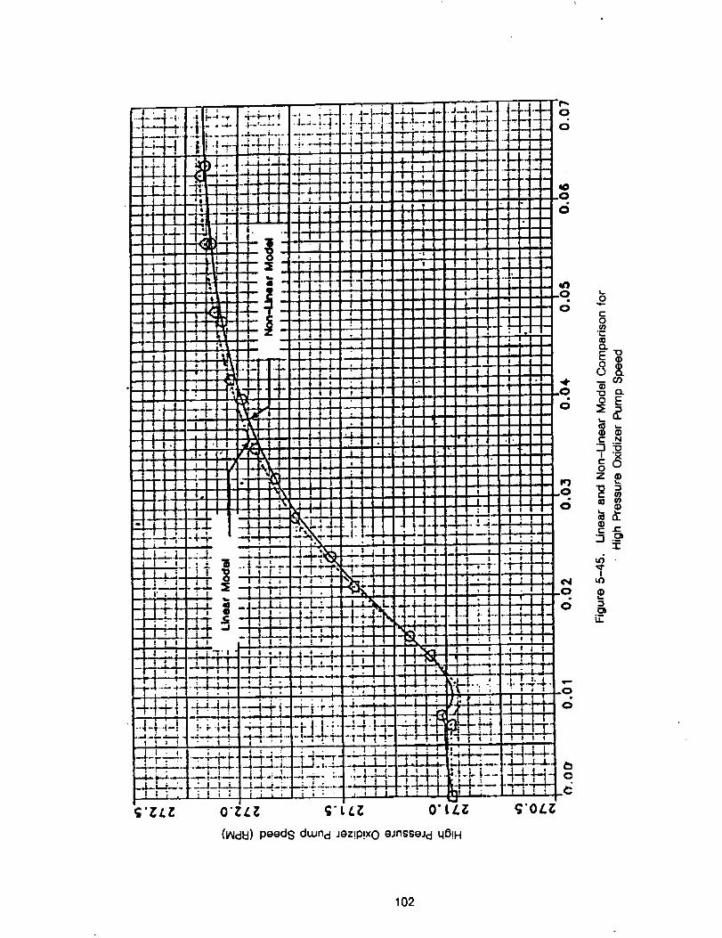
i
!
I
,.l..==
I i | .
ii
J
iI
E0
"E
0
_ ffJ
® ®_ N
"00
z_
e- e-
Y
3
102
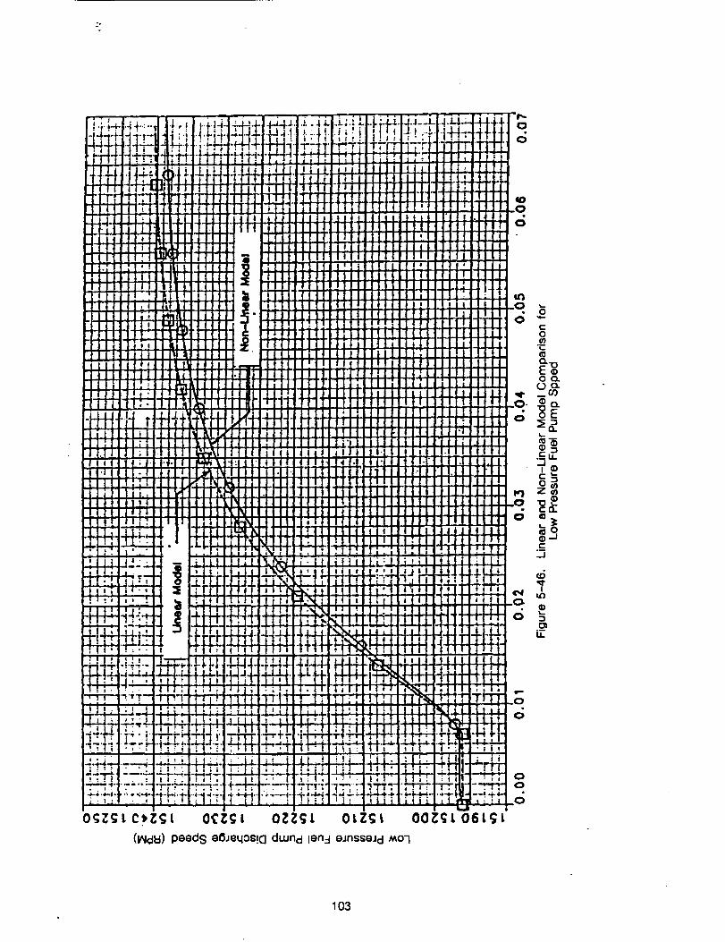
;°
OCZ:; l OZZ;l OLZ;t
(IAIdld) peeds eBJeqos!c] dwnd len:l eJnsseJd _o-I
103
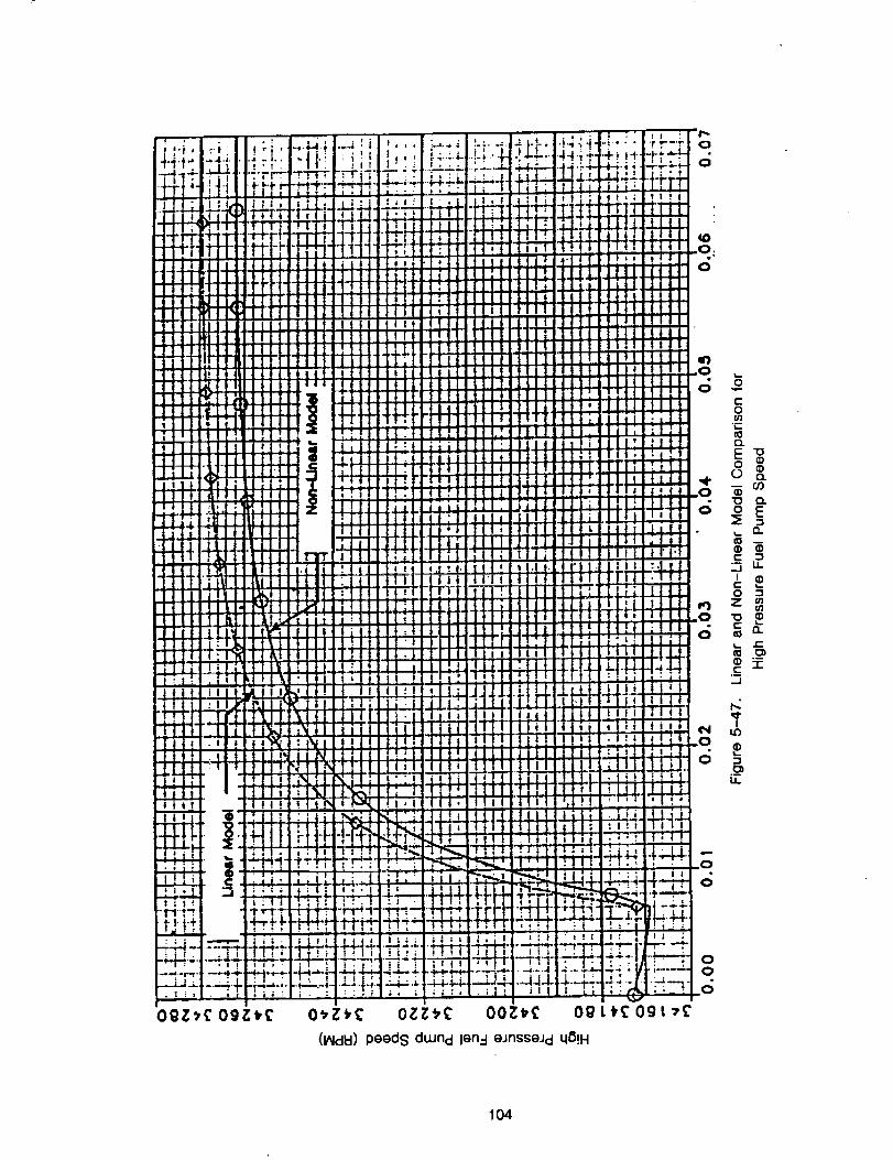
104
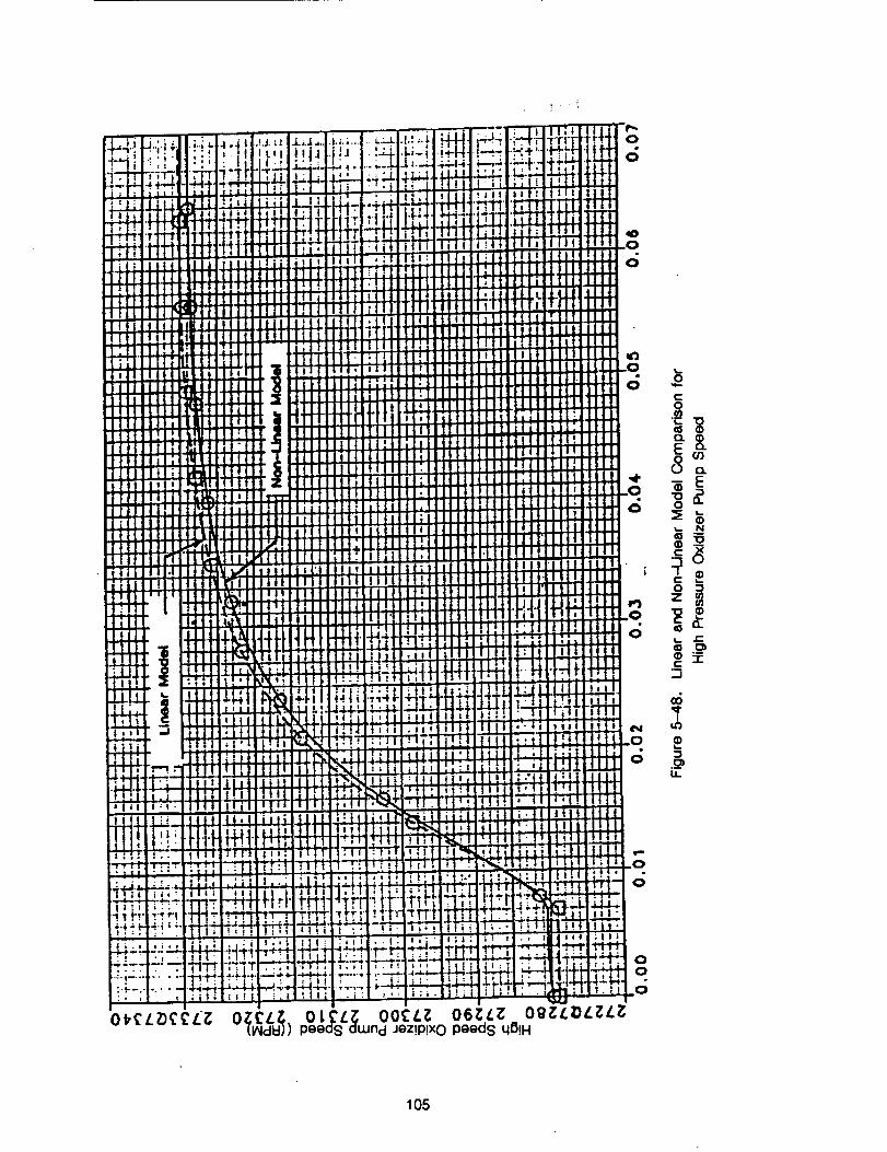
]"r! _" I....• l!
Jale
||l .....lir]lilll
• . . IJlll Ii.I fClt i ilI,l,llllIIIiflI!l-r]lll]_tli
ililllll|!!II i.rlj l;I;IBIll_; ll lqlt
, I I_iI
il I I tlll_
Ill Ittb_t'lllllllill|lI]l_
!111!11[II I i" ....
iiJii
1,4-,ll,dl-l-
= i-:iiI i...e,,i,-4,-i.
I
Ill
I | _
,,,,_ I __t;i ---:_
:i "Jill
_ _tHl-t• • I
• ¶ • i • ! i I
, ill-i,_.l I t i ! ,'i,_lili;
i t -'-t",,"*'+'-
,.;" i '"1
-TI iTl"rT• v- •
,. -i.I4_4.,I ki ti
0 l_eL Z)_'_Li;
Iii
II"t!
'I';
!1
[!
i!
I1
|i
1!
II
Ii
|!
i1II
ii
|1
Ii
I!U.| i
iq
iiII
L|
rr
14-
,!
i!
-iT!
+l!
L
;I
;!
,.zI"I.
O0¢ Zpeeas auJnd Jez!P!xO peeds q_!H
i
EliO b')
E
N
:.3I
O "_
z_
_1
:3
I.L
105

Thispage left intentionally blank.
106
SECTION VI
CONTRACT END ITEMS
This Section presents the 23 contract end items which in general provided the overall
requirements for the simulation system. Each contract end item is presented, followed by the
program accomplishments.
1. The simulation system must have the inherent capability to be applied to current and
projected liquid rocket engine cycles including: Staged combustion, Expander, Gas
Generator, and Tri-Propellant. Projected engine applications include: TTBE, STBE, STME,
and OTVE.
ROCETS is a very flexible simulation system without any built-in rocket engine cycle or
configuration. The user can select component modules and designate the interfaces to
configure virtually any conceivable rocket engine.
The simulation system must simulate start, main stage and shutdown phases of engine
operation.
The TrBE model was operated in all three modes as presented in Section 5 - System
Testing and Verification.
The system must include the capability to operate the plant in both open and closed loop
control. This requires that provision must be made for attaching a control submodel which
may be either sampled data or continuous.
The TTBE model start and shut-down transients were operated open-loop. A NASA-MSFC
FORTRAN control model (Appendix C) was operated closed-loop with the TTBE model in
main stage operation as presented in Section 5 - System Testing and Verification.
Methodology must be created to allow representation of various failure modes and off
nominal operating conditions including random parameter variations within each submodel.
ROCETS was designed with generic component modules which (based on user input) call a
designated sub-module which provides the specific component performance characteristic.
Component failure implies the component performance (map characteristic) changes
drastically. ROCETS can utilize modules which accept a failure flag to switch from a normal
operating characteristic to a failed performance characteristic.
The simulation system shall be organized so that multiple levels of detail may be user
selected for each sub-model where appropriate. This requires that both highly detailed
simulation modes and "quick and dirty" simulation modes may be selected at user
discretion.
ROCETS is designed to configure an engine simulation based on user defined modules which
leaves the amount of model detail up to the user. During the program, a simple TTBE model
and a detailed I'TBE model were generated and operated.
6. The simulation system shall be designed with a minimum bandwidth goal of 300 Hz for the
detailed simulation mode. In some instances it might be appropriate to model higher
frequency dynamics.
ROCETS has several features to enhance transient operation. Integration methods include
trapezoidal and Gear (first and second order), while other methods can be adapted if
.
,
o
.
107
PRECEDING PAGE BLANK NOT FILMED
.
.
.
10.
11.
required in the future. Implicit (closed-loop) integration is recommended for cost-effective
computer operation, but open-loop Euler integration is also available. A relative time
constant is calculated in each module and compared to the simulated time step, to
automatically select integration or differentiation to be used. Therefore, ROCETS can not only
operate models up to 300 Hz, it also operates them in an efficient manner.
The simulation system shall be designed so major system components, i.e., the generic
submodel library, the engine specific data, the generic data, and the simulation experiment
data, will be separate and distinct.
The ROCETS system has component modules with generic calculations which call
sub-modules with specific component performance characteristics and data. Properties are
called when required through a module for each fluid and sub-modules which contain the
various property maps. After a simulation has been configured, the user defines the
simulation experiment with inputs to the run processor.
Input data to define a particular engine shall be defined in terms of desigrl data as opposed
to model parameter data. Likewise, the empirical data necessary to characterize should be
defined in terms of industry standard practice. For example, a dynamic model of a sensor
will usually be given in transfer function form. Turbine performance maps will be
nondimensionalized. This requires that a design data to model data to model data (sic)
translator component be developed.
The ROCETS system was designed with a component-by-component module and
sub-module performance characteristic concept. This allows the user to build-in conversions
of design data to model parameter data as required.
A consistent set of nomenclature, model generation coding style, and documentation
requirements shall be defined and adhered to. This requires that the code must be self
documenting to the extent possible.
The ROCETS system software standards are presented in the SDS, P&W FR-20284
(Reference 4). An example of self-documenting code based on these standards is
presented in Appendix B.
The simulation system shall be designed so that subset simulations may be readily derived
from the transient simulation of an engine. These subset simulations include linear operating
point simulations for controls design, fast operating nonlinear simulations for controls analysis
and parametrics, and real time simulations for hardware-in-the-loop- testing.
ROCETS provides the capability to generate linear partial derivatives around transient, or
steady-state operating points, The matrices of these partials are output by the system for
use in subset simulations or linear control analysis. Because ROCETS can quickly eliminate"
states in the non-linear simulations by forcing the derivatives to zero, it can be used to
develop real-time models which require limited number of states.
The simulation system will provide some method of warning the user when a simulation run
uses out of range data, such as requesting thermodynamic property routines to extrapolate
to 6000 psia when the data is good to 5000 psia. It also shall be the user's option to limit
the warning and/or utilize it as a stopping condition.
This was accomplished with good traceability and warnings arranged in different levels of
severity as discussed in the User's Manual (Appendix A).
108
12.
13.
14.
15.
16.
All generic data and mathematical models utilized in the simulation system shall be
documented in the code such that the user will know the source of the data and will know
the limitations and assumptions under which the data was generated and employed in the
system. Specifically, internal documentation shall include: precise explanation of program
and subprogram purpose, identification of version data and number, identification and
description of all inputs and outputs, and identification of all blocks of mathematical
calculations.
This was accomplished and can be viewed in the example pump module (Appendix B) and in
the other system modules and sub-modules of the SDS (Reference 4).
The simulation system shall be generated in the "Advanced Continuous Simulation
Language" and in FORTRAN 77 unless an overriding justification can be made for an
alternate approach. Such justification would be if an alternative were shown to be obviously
and substantially superior to ACSL, or if a necessary capability were identified which would
be prohibitive to develop in ACSL.
The ACSL requirement was eliminated at the Critical Design Review at MSFC on 21 July
1988, because of the following justification: The ACSL system uses a FORTRAN labeled
common structure to communicate between the ACSL FORTRAN modules. These common
statements are built through an internal algorithm and are not structured in a predictable
format, making user interfacing with ACSL modules very difficult. On the other hand, ACSL
as a system is not structured to generate large, detailed rocket simulations from user
supplied FORTRAN modules and operate the simulation in an efficient manner. Therefore, the
ROCETS system should not be generated in ACSL.
The approach to be taken in mathematical modelling shall always give preference to first
principals models first, empirical correlations second, and a transfer function approach third.
For example, it is important to use first principals models of volume filling and gross heat
transfer when modelling an injector prime. On the other hand, turbomachinery performance
can be obtained by nondimensional performance maps so that simulation run time may be
kept reasonable. Likewise, a sensor model need only be in transfer function form since any
increase in detail would greatly encumber the simulation.
In general, these guidelines were utilized in generating the modules to represent the T'I'BE
model. The module building-block architecture of ROCETS allows component models with
different levels of detail to be substituted if required for particular application.
In general the detailed mode of simulation should be sufficient to reflect the influence as
would be measured by performance instrumentation and reflected in aggregate internal
parameters of the following: design changes, property changes, start phenomena, shutdown
phenomena, control logic performance, key parameters that limit operation like turbine
temperature limits, instrumentation performance and location effects, engine performance
variation, interface condition changes, and purge effects. This list is not all inclusive. The
detail generally required is that reflected in the SSME DTM.
The SSME DTM (Reference 2) was used as a guide to provide the amount of detail in the
"I-I'BE simulation.
The acceptance test of the simulation system shall be a complete simulation of the
Technology Test Bed Engine. All thermodynamic and thermophysical property data generated
for the simulation system must reflect the requirements that the TTBE has for such data.
Likewise, heat transfer correlations must be valid in "I-I'BE operating ranges. To provide
109
17.
18.
19.
20.
21.
22.
capability for the modeling system to be utilized in the study of hydrocarbon engines,thermodynamic and thermophysical data must also be supplied for at minimum the mostlikely hydrocarbon propellant candidate. NASA will specify the choice during Phase II efforts.These statements require that the data is for characterization of liquid hydrogen, liquid
oxygen, hydrocarbon fuel, purge gasses, and their materials utilized in the TTBE.
The TI'BE simulation was generated and used to verify the simulation system. Because ofdecreased interest in tri-propellant engines, NASA did release P&W from the hydrocarbonrequirement at the 14 November 1989 meeting. The P&W system to be delivered will includemethane thermodynamic properties as part of the property package, but will not includecombustion properties of methane. The simulation system will accept data tables ofcombustion properties, and NASA can generate the properties in data table format ifrequired for tri-propellant simulations in the future.
All typical liquid rocket engine components such as turbines, pumps, valves, ducts,accumulators, etc., shall be defined in generic fashion such that they can be connected in
any user desired manner to simulate any of the engines or engine types listed earlier in thisdocument.
The ROCETS configuration processor allows the flexibility to generate simulations of anyengine.
To verify proper operation, all normal operating modes of the TTBE will be simulated in boththe detailed and the quick and dirty modes. In addition, the subset simulation generatior_
capability must be exercised.
As discussed in this report, a simple TTBE model and a detailed TrBE model were generatedand operated. Linear partials were generated and verified by comparing a linear modelprediction with the non-linear model prediction in the time domain.
To verify submodel operation, test requirements defined in task must include testing theoperation of the submodel against known analytical solutions and experimentally verified data,when available in open literature.
The system qualification test plans are written to verify module code by specifying tests to
be performed and the required evaluation, including comparison source and acceptancecriteria. As an example, the values in the property tables were compared to National Bureauof Standards data.
The simulation system shall be installed and proper operation verified on the MSFC EADS IBM3083 computer system.
This was accomplished.
At the completion of each sub-model or component, the code must be delivered to NASAMSFC for testing and utilization, all submodels and components must be delivered at least 3
months prior to contract completion in order to assure timely testing.
The initial software delivery to NASA-MSFC was 27 December 1989, with updates on 5March 1990 and 10 August 1990.
A review visit to MSFC will occur on or about six months intervals. A Critical Design Reviewwill be performed as a part of the first review, with MSFC concurrence required for work toproceed. The results of tasks 1, 2 and 3, in Phase I of the activities shall be delivered as adocument to be utilized in Critical Design Review.
110

-°
The Critical Design Review was conducted 21 July 1988. Other reviews occurred on 9
December 1988, 27 July 1989, and 16 May 1990.
23. The final report will include a section listing the equations utilized with all ROCETS code.
All of the equations of ROCETS are presented in the SDS, P&W FR-20284 (Reference 4).
111

This page intentionally was left blank.
112
7'
SECTION VII
CONCLUSIONS
1 ,
°
,
°
The ROCETS system is a valuable new tool which will save time and money in developing
and using liquid rocket engine transient simulations.
The implicit integration scheme saves computing calculation time, and has been used
successfully with the detailed TTBE model in simulating start, main stage, and shut-down
transients.
The same simulation can be used for steady-state cycle balance as well as transient
operation.
FORTRAN models developed outside the ROCETS system can easily be interfaced with and
operate in the ROCETS system.
_NI[IONN.13 IE/U_K
113 PRECEDING PAGE BLArqK NOT FILMED

This page left intentionally blank.
114
,°.
-°
o
2.
3.
SECTION VIIIRECOMMENDATIONS
The detailed TTBE model should be enhanced by verification with engine data.
The ROCETS system should be maintained with future changes and enhancements.
Potential ROCETS enhancements include:
• All-electronic documentation and on-line user assistance
• Improved linear partial generation technique
115 PRECEDE_JGP_'"_,,,:,,_BLA.r_K NOT F;LP_ED

This page left intentionally blank.
116
.
2.
3.
.
5.
.
o
,
9,
SECTION IXREFERENCES
Pratt& Whitney EngineeringSoftware Development Standards (IDS-T0400)
Space ShuttleMain Engine (SSME) DigitalTransientModel (DTM) 0889
ROCETS System Requirements Specification,Pratt& Whitney FR-20283,
25 November 1988.
ROCETS System Design Specification,Pratt& Whitney FR-20284, 25 July 1990.
Gear, C.W., "Numerical InitialValue Problems inOrdinaryDifferentialEquations",
Prentice-Hall,1971.
Gear, C.W., "The Automatic Integrationof StiffOrdinaryDifferentialEquations",Universityof
lllinois,1969.
Broyden, C.G. " Class of Methods for Solving Nonlinear simultaneous Equations",mathematics of computation, Vol. 19, 1965, pp. 577-593.
McLaughlin, P. "Replicas: A new Continuous System Simulation Language"
Biggs, R. "Space Shuttle Main Engine The First Ten Years", American Astronautical SocietyPaper, November 2, 1989.
117PRECEDING PAGE BLANK NOT FILMED

This page was intentionally left blank.
118= .
Apppendix AUser's Manuel
The User's Manual for ROCETS is contained in the SDS, P&W FR-20284 (Reference 4). It is
reproduced in this report for reference.
119 PRECEDi[_iG PAGE BLANK NOT FILMED
Pral! & Whi(neyFR - 20284
31 May lggo
ROCETS USER'S MANUAL
31 May I990
United TechnologiesPralt & Whitney
Governmen! Engine BusinessWest Palm Beach. Florida
120
Pralt&WhitneyFR-20284
31May1990
Table of Contents
3.4.4,1 INTRODUCTION TO ROCETS ................................................ I
3.4.4.2 GENERAL DESCRIPTION ................................................... 23.4.4.2.1 The Module ........................................................ 23.4.42.2 The Sub-Module ...................................................... 23.4.4.2.3 Variable Tags ..................................................... 23.4.4.2.4 Executive Programs ................................................... 3
3.4.4.3 CONFIGURATION INPUT ........................ .......................... 43.4.4.3.1 OPTIONS Keyword ............................................... 43.4.4.3.2 INSTREAM Keyword ................................................. 43.4.4.3.3 EXTERNALS Keyword .............................................. S3 4.4.3.4 INTEGRATION Keyword ............................................ S3.4.4.3.5 BALANCES Keyword .................. : .......................... $2.4.4.3.6 SYSTEM ABOVE. INSIDE BELOW Keywords ......................... S
34436t MODULESub-BIock .......... _ ............................ 734.43(;2 PROPERTY Sub-Block ......................................... |3,4.4.3.$3 EQUATION Sub-Block ......................................... tO
3.4.4.4 RUN INPUT ........................................................... 1t
34A4.1 SCHEDULES Keyword ............................................. 1t34.4.4.2 INPUT Keywo*'d ................................................. t23.44.4.3 INTEGRATION DEFAULTS Keyword ................................... 133.4.4.4.4 INTEGRATION EXCEPTIONS Keyword .................................. 143.44.4.5 BALANCES Key',_:)rd ................................................. 143.4.4.4.6 BALANCE OEFAULTS Keyword ....................................... 153.4.4.4.7 BALANCE EXCEPTIONS Keyword ................................. 1534.4.4.8 LINEARIZATION Keyword ................................. 163,4.4.4.9 LINEARIZATION DEFAULTS Keyword ........................ 163.4.4.4.t0 LINEARIZATION EXCEPTIONS Keyword ............................. 173.4.4.4.tl RESTART Keyword ..................................... 173.4.4.4.12 OUTPUT Keyword ................................ : ..... 1113.4.4.4.13 RUN Keyword ................................................... 49
3.4.4.$ BUILDING A MODULE ................................................... 213.4.4.5.t Module Communication ........................................ 2134.452 Inlerface Data Section ...................................... 21
3 4.4.5 3 Module PrinilPlol Outpul ......................................... 25
3.4.4.4 SIMULATION DEBUG ...... . ............................................. 2ti3.44.11.1 Err4_r flags ...................................................... 26
3.4.4.7 RUNNING A MODEL ..................................................... 273,4.4.7.1 Running the Configuration Processor (TSO) ............................ 273.44.7,2 Running a configured model (TSOI ................................... 28
.1.4.4
121
Pratt a whitneyFR - 20284
31 May 1990
3.4.4.1 Introduction to ROCETS
ROCETS is an acrom/m rot ROCket Engine Transient Simulalion. The objective Of the ROCETS systemis Io apply the state-ot'-the.arl in modeling and simulalion technology to simulaling liquid rockelengines. The versatility Of this system makes it ideal for the performance engineer, the systemengineer, and the control engineer. Also, the slruclure Of ROCETS makes it highly adaptable losimulate any type of rocket engine cycle with varying levels Of modeling detail as desired by the user.
The ROCETS system is designed for use by engineers with average experience. While extensivemodeling experience is no( requ!red, it is assumed Ihat Ihe user is familiar with modeling practicesand techniques. The goal Of ROCETS is to aid the user in creating and using a simulation byautomatically generating an executable model from input, scanning the model for undefined variablesor variables which require algebraic loops, and supplying slate-of-the-ad numerical lechniques A/lexibfe run-time processor aids in defining inpuls for a parli(:ular model experiment. In addition, theROCETS syslem makes available fully verified engineering represenlalions or most rocket engineCOmponents. The modules in ROCETS which implemenl non.linear engineering represenlations arewrillen in structured FORTRAN77. The system also has provisions Io generate linear partialderivatives at user selected points for subset models
._.4.4I
122
Pratt& WhitneyFR - 2021N
31 May 1990
3.4.4.2 General Description
The ROCETS system implements engineering representation in the form of FORTRAN subroutinescalled "modules" The modules are slored on the ROCETS library and are accessible for generatingsimulations. A configuration processor is used lo generate an execulable simulalio_ from user input.Once a simulation is generated, input is supplied to a run processor to execute a particular simulationexperiment.
3.4.4.2.t The Module
A module in the ROCET$ system is a stand alone FORTRAN 77 subroutine which implements theengineering equations Io represent a particular engine com0onenl A module is distincl from gibertypes of subroutines in thai only modules communicate directly wilh the main program Allcommunication between modules is via the main program using named variables
As part of required user input when defining a particular simulation, each selected module muslinclude = character name to distinguish the variables associaled with thai module from olhervariables in the simulation. The name can be up to four characters The •dual variable names areformed by concatenating the module name with pre- defined syslem names for each type of variable.As an example, consider the variable name for density Inside a volume Let the volume module namesupplied by the user be "VOLI", The system name for density is "RHO" so thai Ihe actual variablename is "RHOVOLt'.
addition to the system names Io be used for the variables of each module a variable "tag" iscorttained in the comment cards at the beginning of each module The variable tag is used to groupall the variables comprising the model into several categories depending on their function in thesimulation. The categories are importanl because only certain variable types can be used for variousfunctions.
3.4.4.2.2 The Sub-Module
Sub-modules are called by modules Or other sub-modules by a FORTRAN subroutine call list. Theyare stand alone subroutines but. unlike modules, they do nol communicate wilh the main program.Sub-modules are divided into map sub-modules and ulilily sub.modules. Map sub-modules =re
performance characteristics representing a particular component The user selects which map 1o usefor a given component along with the ability to "scale" the map Utility sub.modules implement
generalized functions and are typically analytic engineering representations or mathematicalooeratioas.
3.4.4.2.3 Variable Tags
Stales are variables for which derivatives are calculated and whose values will normally be obtained
through numerical integration using a predictor-correclor scheme In addition to slales, there can beState Iteration Variables. These are variables used as the independent variables for the iteration toclose 1he corrector equations. In particular for rockel applications, it is useful to use pressure and
.1.4.42
123
Pratt & WhitneyFR - 20284
31 May 1990
enlhalpy as Ihe ileralion variables for the density and internal energy stales. Firsl guesses for theslates or the slate iteration variables must be st_pplied.
External inputs are variables that are used but never calculaled. They are lagged as external inputsbecause they must be supplied exlernalty in some form by the user
Oesign variables represent variables thai are normally fixed for a given engine cycle. Examples arevolume sizes, line lengths, etc. They have the same function as external inputs but a disiinclion ismade for future system enhancements.
Outputs are simply variables that.are output of a module and may be used as input to other modulesdownstream. No action concerning outputs is necessary by the user.
Independent Balance Parameters are variables that are used as Ihe independent iteration parameterfor an algebraic loop. Oependenl Balance Paramelers are the variables Ihat form the error term.
3.4.4.2.4 Executive Programs
Foul' processors are used in the ROCETS system A configuralion processor reads Ihe userCOnfiguration input, relrieves the specified modules and sub- modules from Ihe ROCETS librarysystem and builds the simulation. In setting up the simulation, the processor builds thecommunication slructure along with global commons It also builds the main program (subroulineROCETSJ with the calls to the engineering modules, and any properly calls or equations as specifiedin the configuralion Jnpul.
An inpul processor is used 1o interpret user Input specifying parameters to define a parlicutar modelexperiment. I1 consisls of a sel of callable FORTRAN subroutines Ihat read user input, inlerpret theinput, can load input variables Inlo lhe commons, establish balances, and set necessary flags formodel execution.
Execution control is provided by an execution processor I1 controls looping, print, balancing, andlinearization. Within the execution processor are calls to the numerical utilities that providesteady-stale balancing, translenl integration, and linearizalion I! provides a centralized Iocali.o_. forall numerical operations so Ihat adding new features Io Ihe syslem is simplified
Oufpul processing is controlled by an output processor thai accepls input as to what parameters areto be printed and ploHed It has an interface routine for piol information so that il can be used witha variety of pioUing software simply by changing Ihe interface rouline. However. linearization outputis not conlrofled by the output processor, but ralher all necessary information is passed to a separateinterface routine for linearization output. This feature allows tailoring of the linearization output by
changing only the inlerface routine
.1.4.4J
124
l,+rlll Ii Wfll|neyFR - 20284
31 May 1990
3.4.4.3 Configuration Input
¢onfigteration inp_ consists 04 user commands to build a padicular simulation. II consisls 04 requiredink,'malign regarding the algebraic engineering modules to be used and their placement. The systemIo be modeled is de_ned using the following keywords"
OPTIONSINSTREAMEXTERNALSINTEGRATIONBALANCESSYSTEM ABOVE. INSIDE. or 6ELOW
3.4.4.3.1 OPTIONS Keyword
The options block conlains optional input to Ihe processing program and should be located at the lop04' Ihe configuralion input file. Included are engineering units oplions, provision (or a lille, provisio_for specifying a PUS for Ihose operating on MVSITSO. and a cross reference option. The form 04 theOPTIONS block is:
DEFINE OPTIONSUNITS , ( ENGLISH or 5I | ;TZTLE s ( The title ef the modal to be configured } ;PDS , { Data dietio_ry file name ) ;CROSS , ( 0H / OFF } ;
END QPTIONS
The UNITS keyword is used to specify the engineering units Io be used. Unils must be eilher ENGLISHor SI
The TITLE keyword is used to specify a 50 character title Ihal will be placed al the lop 04 Ihe mainFORTRAN pro0ram.
The POS keywo_rd is used to specify the name or the file which contains the data dictionary This fileshould Contain the INTERFACE. UNITS. and KEYWOROS blocks for all 04 Ihe modules that are in theR(X_TS Syslem
The CROSS key'_vord is used to turn Ihe cross reference output true the configuration processor On
or O_. The cross reference oulpul conlains an alphabetized list of every occurrence o( everyparameter in the model (with the exception o( some global variables like IPRPL and IUPOATE). Thecross reference output can be very useful in debugging a simulalion and in verifying thai theco+sfiguration processor produced Ihe desired simulalion.
3.4.4.3.2 INSTREAM Keyword
The define inslream block conlains a list 04 modules to be used which are nol in Ihe system. The lisl
includes bolh Ihe module name and a designation of Ihe file in which the module source code resides.For CMS users the file designation consisls of a file name. a file lype and a file mode For MVSITSO
.1.4.44
125
Pratt & WhitneyFR - 20284
31 May 1990
users the file designation is the complete file name The process_ will read each file and interpretthe Interface' infcM'mallon. The format is:
DEFINE INSTREAN( Module n_e ) , ( File desfgnetfon } ;
( Module n4_NI, | ,'{ File desfgn.ffon J ;END INSTREAM
Fo¢" example, if you wanted Io test a new heat irans(er module that is named HEATOS and is in aFORTRAN file named NEWHEAT on your O-disk Ihe DEFINE INSTREAM block would have the form:
DEFINE INSTREANNEATOS , NENHEAT FORTRAN D;
END INSTREAN
Iro_rMV_TSO, the DEFINE INSTREAM block might have Ihe form"
DEFINE |NSTREAMNEATO$ , ABCDI2$.NENHEAT.FORTRAN;
END INSTREAM
3.4.4.3.3 EXTERNALS Keyword
The define externals block contains a list of external inputs to Ihe simulation. The variables must beseparated by a comma and Ihe iisl must end wilh a semicolon. These are variables which are usedbut never calculaled. The processor requires this information Io scan for undel_ned variables andrequired balances
DEFINE EXTERNALS(Variable name list}
END EXTERNALS
For example. Io have a lank pressure and enthalpy as inputs to the model the DEFINE EXTERNALSblock would have Ihe form: " "
DEF|NE EXTERNALSPTflTNK,NTHTNK;
END EXTERNALS
3.4.4.3.4 INTEGRATION Keyword
The integration block allows I change of iteration variables lot implicit integration. Wilhpredictor-corrector melhods, it is not necessary that Ihe slale be Ihe iteralion parameter. The mostcommon example O4 ibis k_r rocket applications is Ihe choice O4_leraliOn variables kx thermodynamicstates. The engineering states are generally densily and internal energy. However. density andinlernal energy are difficult to provide first guesses for. and more imporlantly, they are difficultparameters to Iterate upon. Belier convergence is achieved by ileraling on pressure and enlhalp/tosatisfy the density and internal energy corrector equalions. The form o/the INTEGRATION block is;
DEF|NE ZNTEORATIONITERATE, ( v,e } for ( sfe_e }
END |NTEGRATXON
If a change o4 iteration variables for stales is being used, it is specified by the ITERATE keyword,followed by the desired iteration parameter and the state E:x which it is to be used. I( there is nochange o4 iteration variables then nothing needs to be be specil_ed in the DEFINE INTEGRATION block.
.1.44
, 126
Pratt & WhitneyFR - 20284
31 May 1990
An example of an integration block for a volume thai models Ihe dynamics for a single consliluent fluidand uses a change o4'iteration variables follows:
DEFINE INTEGRATIONITERATE , HTVOLI for UTVOLI ;ITERATE z PTVOL| for RHOVOLI ;
END |NTEGRAT|OH
3.4.4.3.5 BALANCES Keyword
This block is used to define algebraic balances at configuralion time. It is normally used for requiredalgebraic balances, however il is often useful to set-up olher commonly used balances atconfiguration time. The format is.
DEFZNE IALANCESbalance ( b.Zn4,ge ) ( vat ) until ( vat ) = ( vat } ;
END IALANCES
The functional kxm has up to an $ character name to uniquely identify the balance followed by anindependent parameler name to be iteraled until two dependenl variables will be equal A problemIrises when a module output is used as anolher module's i_pul before the output has been calculatedand the parameters have the same name It would be desirable to simply concalenale a tag. a 'C' forexample, on lo the end of one 04 the parameter names However, for most syslems the maximum
• number of characters a variable can have is eight, all of which could be used when following IheROCETS nomenclature. So a 'C" cannot be concalenaled on Io the end 04 Ihe variable name
Therefore the configuration processor assigns a system defined parameter name (of theSYBL000N) Io the second occurrence Of the parameter. Once the configuration processor hasassigned the system name. a balance can be set up to drive the parameter in queslion to be equallo the system defined parameter.
For example, suppose you wanled to calculate pressure upslream or a pipe bul lhat pressure has
been defined as a stale for the volume upstream 04 the pipe. The configuration processor would tagthe pressure upstream 04 the pipe as requiring an addilional balance and would rename one of the_'essures with a syslem dermed name To achieve a balance, the independenl parameter WPIF_ isvaried until the upslream pressure is equal Io the volume pressure A balance can be set up in thefollowing form and the model reconfigured
Balance PUPIIAL , i'ePXPE Until PUP • SYIL0001 i
If it is desired Io establish a balance to drive a dependent variable to a conslanl value, a name shouldbe assigned to the requesled value and then used as the second dependent value. The requestedvalue must also be added to the external input list. An optional method would be to sel the balanceup at run time instead o4'configuration lime
3.4.4.3.6 SYSTEM ABOVE, INSIDE, BELOW Keywords:-:,
The engineering representation for the simulallon is specified in the SYSTEM blocks. Sub-blockswithin the SYSTEM blocks are used in specifying engineering modules, thermodynamic properties andequations. The SYSTEM ABOVE keywoed directs the various sub-blocks wilhin the SYSTEM ABOVEblock to be placed above the iteration loop Likewise, the SYSTEM INSIOE keywo_d directs the varioussub-blocks within the SYSTEM INSIOE block Io be placed inside the ileration loop Finally. the SYSTEMBELOW keyword directs the various sub-blocks within the SYSTEM BELOW block to be placed belowthe ileraflon loop. The form 04 Ihe SYSTEM blocks is:
?,.4.46
127
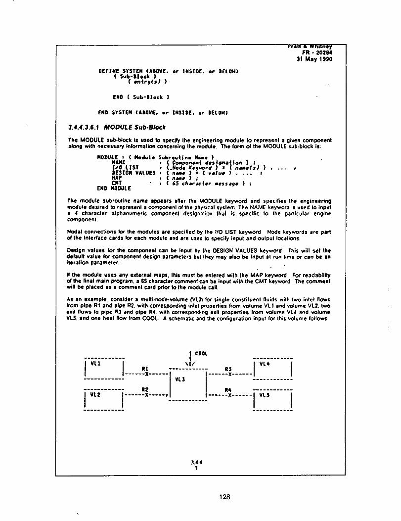
rrat[ • whitneyFR - 202M
31 May 1990
DEFTN[ SYSTEH (ABOVE.( Sub-Block )
(entry(s) )
or INSIDE. or BELOH)
END ( Sub-Block )
END SYSTEM (ABOVE, or INSIDE, or BELON)
3.4.4.3.6.1 MODULE Sub.Block
The MODULE sub-block is used to specify the engineering module to represent a given componentalong wilh necessary information concerning the module. The form of the MODULE sub.block is"
MODULE , ( Module Subroutine Name )NAME , ( Co_onent desf#na(fon } ;Z/O LZST , {.Node Kegword ) • (ndme(s) } ,DESIGN VALUES , ( nw } : { v,lue ) o ... ;MAP , { ndme } ;CMT : ( 65 character aessage } ;
END MODULE
The module subroutine name appears after Ihe MODULE keyword and specifies Ihe engineeringmodule desired to represenl a componenl of Ihe physical syslem. The NAME keyword is used Io inpula 4 characler alphanumeric component designation Ihai is specific 1o Ihe padicular enginecomoonenl.
Nodal connections k_ the modules are specified by Ihe I/O LIST keyword Node keywords are parlof the interface cards for each module and are used Io specify input and oulpul locations.
Design values for Ihe component can be input by Ihe DESIGN VALUES keyword This will sel thedefault value for Coml:x)nenl design parameters but they may also be input al run time or can be anIteration parameter,
N the module uses any external maps. Ibis must be enlered wilh lhe MAP keyword For readabilifyof the final main program, a $S characler commenl can be input wilh Ihe CMT keyword The commentwill be placed as a comment card prior to Ihe module call.
AS an example, consider a multi-node.volume (VL3) for single consliluenl fluids wilh Iwo inlet flowsfrom pipe R1 and pipe R2, with corresponding inlel propedies from volume VL1 and volume VL2. twoexit flows Io pipe R3 and pipe R4. with corresponding exit properties from volume VLd and volumeVLS. and one heat flow from COOL. A schematic and Ihe configuration input for this volume follows
I COOL
i;r_......i ., "'" . iv_;......i:..........:......*......i;::......i......*......:..........:i ......i...........I I.................i
.'1.4.4?
128
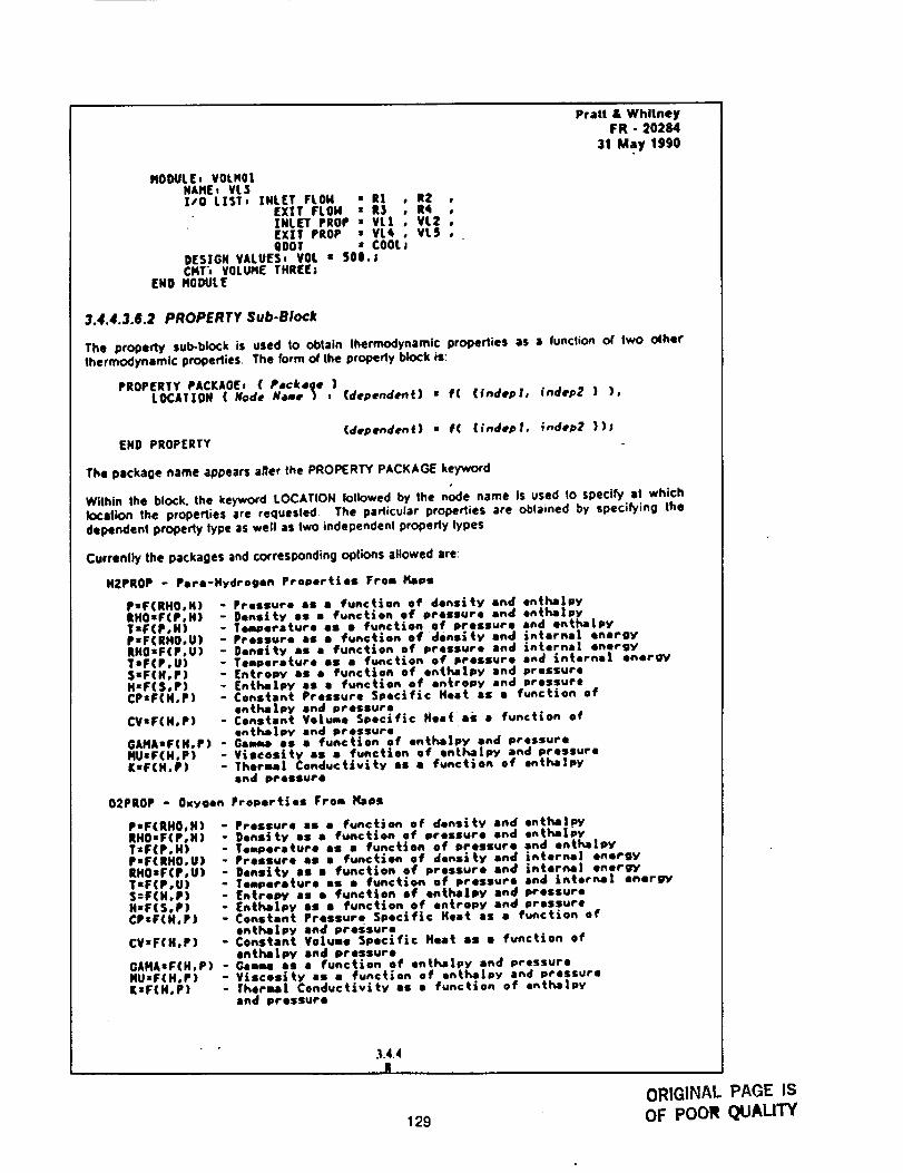
Pratt&WhitneyFR- 20284
31May1990
NOOULE,¥OLHOINAHE. VL$I/O LIST. INLET FLOH • RI , RZ ,
EXIT FLOH • R$ , R4 ,INLET PROP : VL| , VLZ °EX|T PROP • VL_ , VLS 0COOT • COOLJ
DESIGN VALU[S. VOL : 50e.;CMT_ VOLUHE THREE;
EHO _DULE
3.4.4.3.6.2 PROPERTY Sub-Block
The property sub-block is used to obtain thermodynamic properties as a function or two otherthermodynamic properties The form o/the property block is:
PROPERTY PACKAgEs ( Pmck,ge )LOCATION( Mode Hd.ne ) . (dependent} • f( (indepl, indep2 ) ),
(dependent} • f( (;ndep|, fndep2 ));END PROPERTY
The package name appears aner the PROPERTY PACKAGE keywordJ
W11hin the block, the keyword LOCATION _llowed by the node name is used to speci_ al whichkxat_n the prope_ies are requested, The padicular properties are oblained by speci_ing thedependent properly lype as well as two independenl property types
Currenlly the packages and corresponding opines allowed are:
HZPROP - Pare-Hydrogen Properties From Kaps
P:F(RHO,H) - Pressure as I function of density end enthalpyRH0sF(P,H) - 0easiLy el I function of pressure end entha|pyT=F(P,H) - Te_merature as s function of pressure and entha|pyP=F(RHO,U) - Pressure as I functlen of density and _nternl| energyRHO•F(P°U) - Oens|ty as I fence|on of pressure and interne/ energyTIF(P,U) - Temperature el I function of pressure end interne| energySzF(H,P) - EntroPY as • function of enthalpy and pressureH'F(S,P) - [ntl'_Lpy as s function of entropy and pressureCPzF(H,P) - Constant Pressure Specific Heat as a function of
ent_lPy end pressureCV•F(H°P) - Constant Vo|ume Specific Heat as s functlon of
entha|py and pressureGAHA.F(H,P) - Gem IS J functlon of ent_|py end pressureHU•F(H,P) - V_scosity el I function of ontha|py end pressureK•F(H,P) - Theraa| Conductivity el I function of entha|py
end pressure
02PROP - Oxygen Prepare|as From Naps
P,F(RH0,H) -RHOIF(P,H) -T,F(P,H)P•F(RHO,U) -RHOsF(P,U) -TsF(P,U)5"F(HoP) l
H*F(S,P)CP•F(H,P)
CV•F(H,P)
GAHA•F(H.P) -HU=F(H,P) -K•F(H,P)
Pressure as = function of density end ontl_|py0ensity is a function of pressure end entha|pyTemperature as I function of pressure end enthalpyPressure el I function of denslky and _nterne| energy0easiLy IS i function of pressure end interne| energy,Teapariture as I function of pressure and interne| energyEntrepy as • functiofl ef enthalpy and pressureEnthaJpy as i function of entropy end pressureCenstentlPrassure Specific Heat as a function ofentha|py end pressureConstant Vo|ume Specific Heat as i function ofentha|py and pressureG4n_ eS t function Of entha|py end pressureV_lCeSity as I functlen of enthe|py and pressure|harms| Conductivity as i function of entha[pyand Pressure
,1.4.4I
129
ORIGINAL PAGE IS
OF POOR QUAUTY
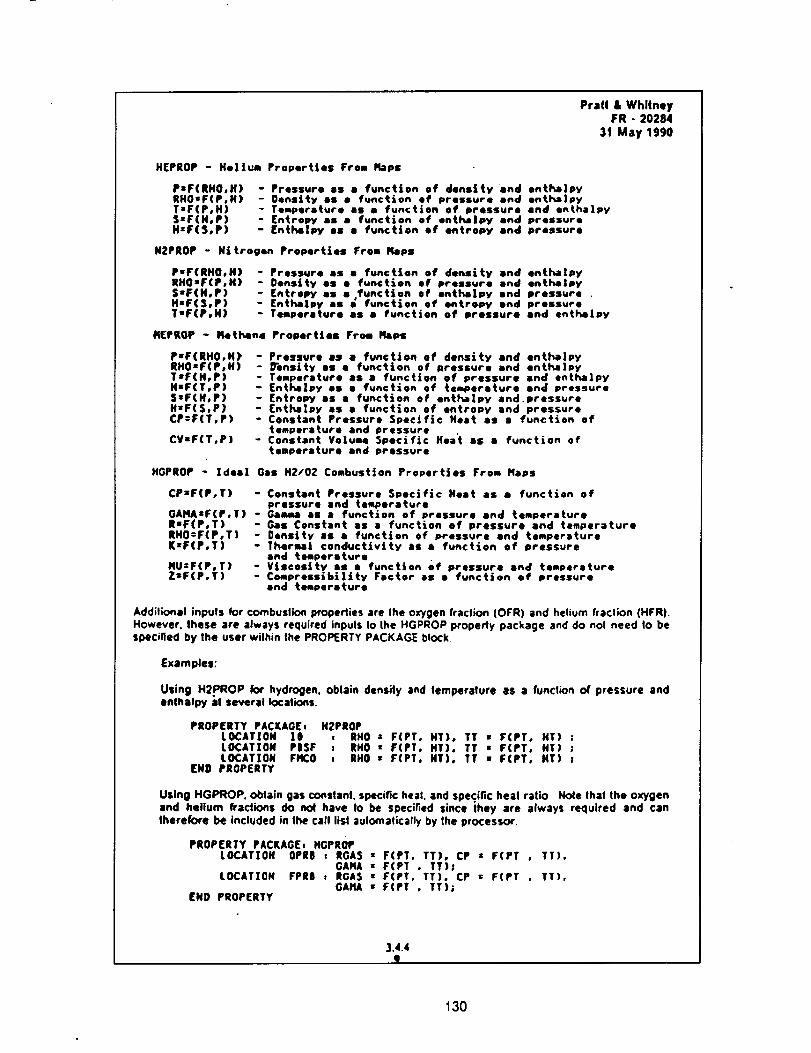
Prafi & WhllneyFR - 20284
31 May 1990
HEPROP - Helium Properties From Hops
PaF(RHO,H)RHOtF(P,H)T:F(P,H)SzF(H,P)H=F($,P)
- Pressure as • function of density and ontha|py- Density aS • function of pressure and enthalpy- Temperature aS a function of pressure end enthalpy- Entropy as • function of enthaipy end pressure- Enthelpy as • function of entropy and pressure
N2PROP - Nitrogen Properties From Flaps
P-F(RHO,H) -RHO-F(P,H) -S'F(H,P)HaFtS,P)T-F(P,H)
KEPROP - Methane
PIF(RHOoH) -RHO'F(P,H) -TeF(H,P)H'F(T,P)S'F(H,P)H'F(S,P)CP:F(T,P) °
CV-F(T,P) -
Pressure as a function of density end enthalpyDensity es • function of pressure end enth_lpyEntropY as e,function of entha|py end pressureEnthaIpy as • function of entropy end pressureTimperoture as • function of pressure and onthelpy
Properties From Flaps
Pressure as • function of density and enthalpy_ensity as • function of pressure and onthalpyTemperature as a function of pressure and onthaipyEntl_lXpy OS 8 function of temperature and pressureEntropy es • function of enthalpy and.pressure(nthllpy es • function of entropy and pressureConstant Pressure Specific Heat as I function oftemperature and pressureConstant Volume Specific Heat as i function oftemperature and pressure
HGPROP - Idea| Gas H2/02 Combustion Properties From Naps
CPzF(P,T) - Constant Pressure Specific Heat as • function ofpressure end temperature
GAHAsF(P,T) - Gamma el a function of pressure and temperatureRsF(P,T) - Gas Constant as • function of pressure and temperatureRHO:F(P,T) - Density as • function of pressure and temperatureK:F(P,T) -Therma] conductivity as a function of pressure
end temperatureHU:F(P,T) - Viscosity el • function of pressure end temperatureZsF(P,T) - Compressibility Factor as • function of pressure
and temperature
Additional inputs for combustion properties are the oxygen fraction (OFR) and helium fracl;on (HFR)However. these are always required inputs Io the HGPROP property package and do eel need !o bespecified by lhe user within Ihe PROPERTY PACKAGE block
Examples:
Using HgPROP kx hydrogen, obtain density and temperature as a function of pressure andenlhalpy at several locations.
PROPERTY PACKAGE,LOCATION 10LOCATION PISFLOCATION FIeCO
END PROPERTY
HZPROPI RHO • F(PT. HT), TT • F(PT, HT) ;I RHO " F(PT, HT), TT • F(PT, HT) ;! RHO r F(PT, HT), TT • F(PT, HT) ;
Using HGPROP. obtain gas constant, specific heat, and specific heat ratio Hole that the oxygenand helium _a_k)ns do no( have to be speci_ed since they are always required and cantherefore be included in the call list aulomatically by the processor.
PROPERTY PACKAGE, HGPROPLOCATION OPR8 : RGAS = F(PT, TT), CP z F(PT , TT),
GAHA : F(PT , TT)ILOCATION FPRJ . ROAS = F(PT, TT), CP : F(PT , TT),
GAHA • F(PT , TT);END PROPERTY
3.4.4I
130
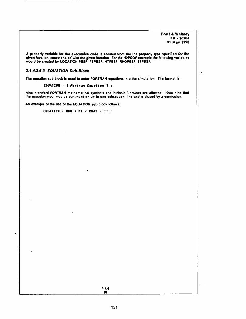
Pratt & WhitneyFR - 20284
31 May 1990
A property variable lot the executable code is created from the the properly type specified for thegiven location, concatenated with the given location. FourIhe H2PROP example Ihe following variableswould be created Io4' LOCATION PBSF: PTPBSF. HTPSSF. RHOPBSF. TTPBSF.
3.4.4.3.6.3 EQUATION Sub-Block
The equation sub.block is used to enter FORTRAN equations into the simulation The format is:
E¢)UATTON , (iror_r4n Equ,e_ion } ;
Most slandard FORTRAN mathemalical symbols and intrinsic funclions are allowed. Hole also thatthe equation inpul may be continued on up to one subsequent line and is closed by a semicolon.
An example o1'the use o( the EQUATION sub-block follows"
[QUAT[OM , RHO z PT / RGAS / TT ;
131
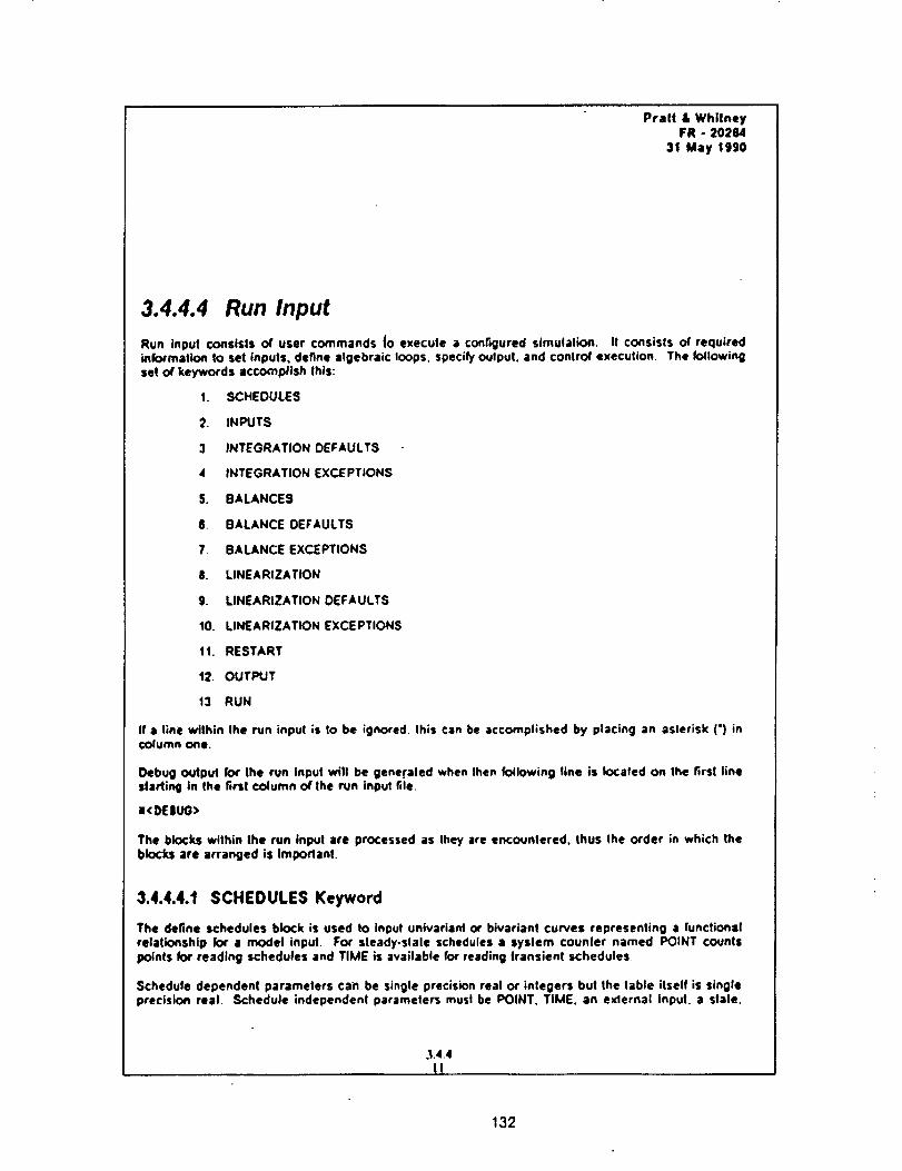
Pratt• WhitneyFR- 20284
3t Maytggo
3.4.4.4 Run Input
Run input consists of user commands {o execute • configured simulation. It consisls of requiredinform•lion to set inputs, define algebraic loops, specify oulput, and conlrol execution. The k:_lowingset of keywords •ccocnplish Ihis:
1. SCHEDULES
2. INPUTS
3 INTEGRATION DEFAULTS
4 INTEGRATION EXCEPTIONS
5. BALANCES
6. BALANCE DEFAULTS
7 BALANCE EXCEPTIONS
8. LINEARIZATION
g. LINEARIZATION DEFAULTS
10. LINEARIZATION EXCEPTIONS
tl. RESTART
t2. OUTPUT
t3 RUN
If a line within Ihe run input is lo be ignored, this can be accomplished by placing an asterisk (') incolumn one.
Debug output for the run input will be generated when then following line is located on the first linestarling in the first column of the run input file.
•<DEIUG>
The blocks within the run Input are processed as they are encountered, thus the order in which theblocks •re arranged is Important.
3.4.4.4.1 SCHEDULES Keyword
The define schedules block is used to input univari•nt or biv•riant curves representing • functionalrelationship for • model input. For steady-slale schedules • system counler named POINT countspoints for reading schedules and TIME is available for reading transient schedules
Schedule dependent parameters can be single precision real or integers but the table itself is singleprecision real Schedule independent paramelers musl be POINT. TIME. an exlernal input, a stale.
3.4.4
1i
132
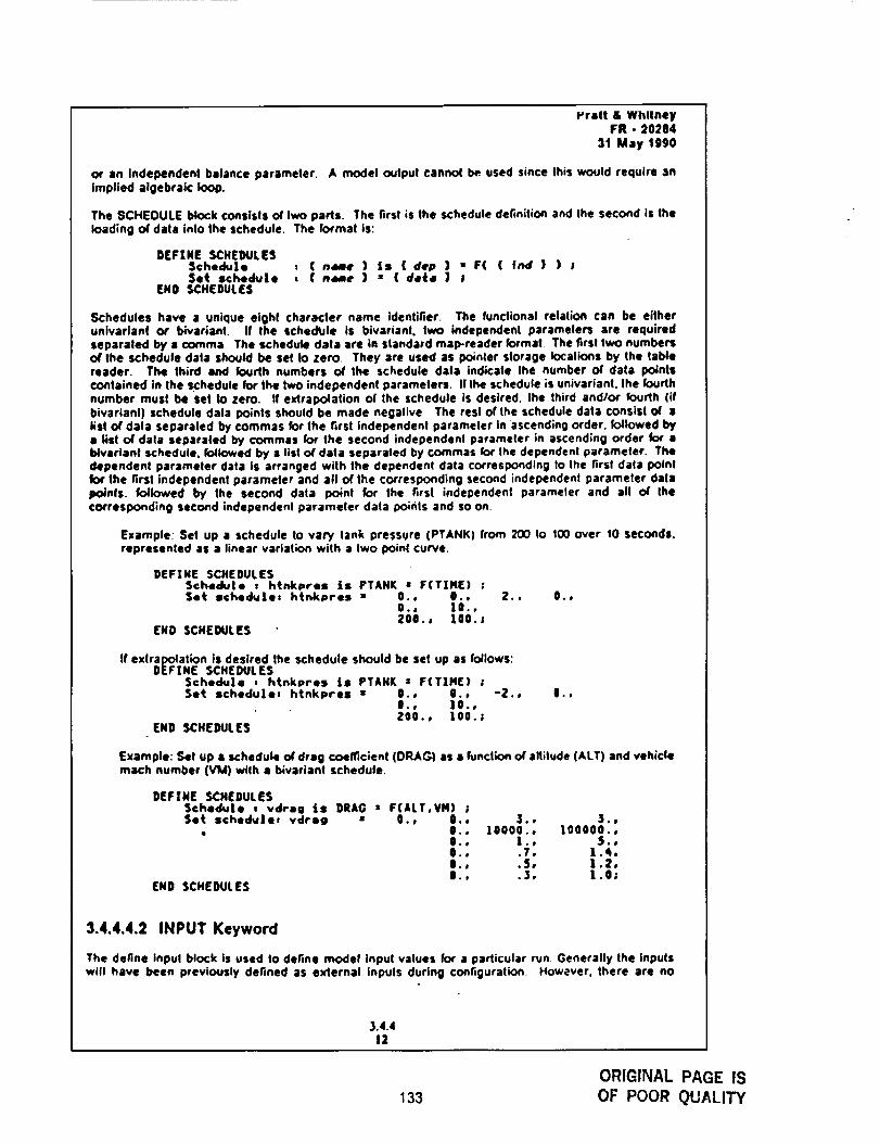
vratt & WhitneyFR - 20284
31 May 1990
_' •n Independenl balance parameter. A model output c•nnol be used since this would require :inImplied algebraic loop.
The SCHEDULE block consists of two parts. The first is the schedule definition and Ihe second is theloading of data into the schedule. The format is:
DEFZNE SCHEDULESSchedule , ( ndme ) is ( dep ) • F(Set schedule , ( ndme ) • ( deS, ) I
END SCHEDULES
lind}) ;
Schedules have • unique eight character name identifier. The functional relation can be eitheruniv•rlan( or bivariant. If the scheDUle is bivarianl, two independent paramelers are requiredseparated by a comma The schedule dale are in standard map-reader format The firsl two numbersof the schedule dale should be sel to zero. They are used as po;nler slorage Iocalions by the tablereader. The third and fourth numbers of the schedule data indicate the number of data pointscontained in the schedule for the two independent parameters. I! the schedule is univarlanl, the fourthnumber must be set to zero. If exlrapolation o( the schedule is desired, the third and/or fourth (ifbivarlanl) schedule dala points should be made negative The resl of the schedule data consist of alist of dala separaled by commas for Ihe firsl independent par•meier in ascending order, followed bya lisl of data separaled by commas for the second independent parameter in ascending order for •I_ivarlant schedule, followed by a list of dala separated by commas k:)r the dependent parameter. Thedependent parameter data is arranged with the dependent data co_responding to Ihe first data pointfor 1he first independent parameter and all of the corresponding second independenl par•meier dale_oJnfs. followed by the second data point for the firs( independenl par•meier and all of thecorresponding second independenl parameter data points and so on.
Example: Set up • schedule to vary lank pressure (PTANK) from 200 to 100 over 10 seconds.represented as a linear variation wilh a two point curve.
DEFTHE SCHEDULESSchedule , htnkpres |s PTAHK • F(TZHE) ;Set schedule: htnkpres : 0., 0.,
0., lO..200.° lO0.J
END SCHEDULES
2,1 O.p
If exlrapolat;on is desired the schedule should be set up as follows:DEFINE SCHEDULES
Schedule , htnkpres Is PTAHK s F(TZM() ;Set schedule, htnkpres : 0., 0., -2.,
0., 10.,200., ! 00. ;
END SCHEDULES
O°*
Example: Set up I schedule of drag coemclent (DRAG) as • function of allitude (ALT) and vehicleroach number (VM) with a bivariant schedule.
DEFZN[ SCHEDULESSchedule , vdrag ts DRAG : F(ALT,VH) ;Set schedvJeJ vdreg : 0., 0., 3., $.,
• O., I0000., lO0000.,0., I., S.,0., .7, 1.4,l., .5, 1.2,l., .3, 1.0;
END SCHEDULES
3.4.4.4.2 INPUT Keyword
The define inpul block is used to define model input values for a parlicular run. Generally the inpulswill have been previously defined as external inputs during configuration. However. there are no
3.4.412
133
ORIGINAL PAGE IS
OF POOR QUALITY

Pratt & WhitneyFR - 20284
31 May lgg0
restrictions on whal may be a_ualiy input Inputs from • schedule are specified by enlering thekeyword SCHEDULE and the schedule name The formal is.
DEFINE INPUT( v•rn_ee ) : ( date )( varnamf } . schedule
END INPUT"( schedule nd_e } ;
The following example shows how Io define inputs from a schedule and various model input values
for a particular run:
DEFINE INPUTPTIN = schedu|e PIPE_BC ,CF • 95.0 ,RPL z 65.0 ;
END INPUT
3.4.4.4.3 INTEGRATION DEFAULTS Keyword
The integration defaults block sels-up default inlegratlon inlormation at run time. It is generally easiertO tel-up default information which is adequate for most stales and then Io override Ihe defaults k:,rspecific slates when necessary. The form is:
DEFINE INTEGRATION DEFAULTSMe_hodConvergence CriteriaTolerancePerturbationAllowod ChangeState BiasStake Norl, mltzer
END INTEGRATION DEFAULT5
( keyd_:rd ) ;( keyword ) ;( v.Zue ) ;( vaZue ) i( veZue ) ;{ va].# } l( value } ;
The method keywords allow user select/on of the inlegration technique within the 1,mils allowed by theInlegration method selected at configuration. Currently there are no limits, but as new integrationroutines are added limits will be necessary. Current methods are EULER. TRAPEZOIOAL. GEAR 1STand GEAR 2NO WARNING: If the balances are on or the slale iterafio_ variables are active whenusing the Euler method an error will occur.
For predictor-corredor schemes, the corrector equation is tier•ted lo convergence using amulti-variable Newlon-Raphson meihod The multi.variable iteration routine includes internalJacobian scaling to improve convergence with stiff systems. In effect both the rows and columns arenormalized by the maximum element in the.row and column The error term used _ convergencelasting can be the actual error o4"it can be normalized as pad as pad of the Jacobian conditioning
Convergence crileri•, tolerance, perturb•lion, and allowed change apply only to tier•live methods.The keywords to specify the convergence crileri• are ABSOLUTE ERROR or NORMALIZED ERROR.
Tolerance is defined as how close Io zero Ihe error term must be bekxe solution is considered
converged Experimentation to delermine a good tolerance value is usually necessary.
The perturbation is the amount each independent variable is moved for generating a Jacobian II is
specified as a percenlage of the biased slale, input as • decimal traction. The allowed change is theamount an independent variable is allowed to change each pass This is necessary in non.linearsyslems to prevent excessive movement leading 1o exceeding map bounds, etc The allowed changeis also • percenlage aT Ihe biased slate, input as a decimal traction
The state bias is the value that is to be added to the slate to bias the slale This is necessary if the
stale is going Io change sign or approach zero during the run. The stale normalizer is Ihe value Ihatthe slale is to be divided by !o normalize the slale for Ihe firsl point If the slate normalizer is set to
,I .4.41.1
134
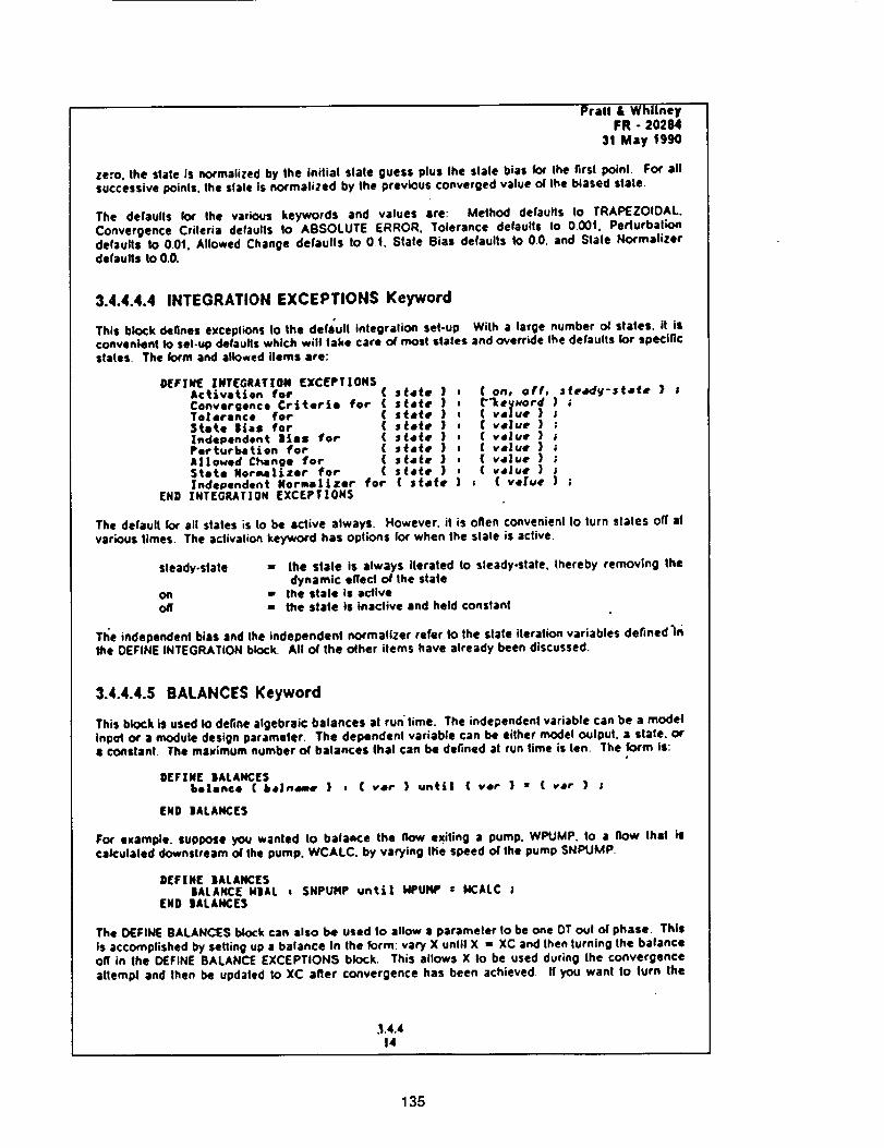
Pralt • WhilneyFR - 20284
31 May 1990
ze:o. the stale is normalized by the iniliat slate guess plus Ihe slate bias for the firsl point. For allsuccessive points, the slale ts normalized by the previous converged value ot Ihe biased state.
The defaulls for Ihe vark:)us keywords and values are: Method defaults Io TRAPEZOIDAL.Convergence Criteria defaults Io ABSOLUTE ERROR, Tolerance defaults Io 000t, Perturbal;ondefaults to 0.0t. Allowed Change defaults to 01. Stale Bias defaults 1o 00. and Stale Normalizerdefaults to 0.0.
3.4.4.4.4 INTEGRATION EXCEPTIONS Keyword
This block defines exceplions to the defa'ul! inlegralion set-up With a large number oi stales, it isconvenient to sel-_ defaulls which will take care o( most slates and override Ihe defaults for specificstales. The k_'m and allowed items are:
D[F|HI[ INT(GRATION (XC[PTIONSActivation for ( s_ete )Convergence Criteria for { s(ete )To|stance for ( s(e_e }$_ate Bias for ( stets )Zndependent |les for ( state )Perturbation for ( s_atq )Allowed Change for ( s(a_e )State Normal_zer for ( s|4_e )Independent Norma|izer for ( stele
END ZNTEGRAT|0N EXCEPTZON$
( on, off, J_eedy*s(afe } ;
( value ) ;( value ) ;( veluf ) ;( v,lue ) ;( value ) ;( v,lut ) ;
( value ) ;
The default for all stales is to be active always. However. it is often convenienl Io turn stales off atvarious times. The aclivalion keyword has options for when the slale is active:
steady-slate
onoff
•- the stale is always iterated to sleady-state, thereby removing thedynamic effect otr the state
•, (he s(afe is ac/ive,- the state is inactive and held constant
Tt_e independent bias and the independent normalizer refer to the slate iteration variables defined'in
Ihe DEFINE INTEGRATION block. All oi' the other items have already been discussed.
3.4.4.4.5 BALANCES Keyword
This block is used 1o define algebraic balances al run'time, The independenl variable can be a modelinpgt or a module design parameter. The dependent variable can be either model output, a state, ora constant The ma)cimum number ot balances that can be de_ned at run lime is len. The form is:
OEFiNE |ALANCESl_]a_c. ! b,pJn,_,, )
END IALANCES
, ( v,r ) unt$!
For example, suppose you wanted to balaece the IIow exiting a pump. WPUMP. to a flow Ihat iscalculated downstream o/Ihe pump. WCALC. by varying the speed of the pump SNPUMP.
DEFINE |ALANCE5IALANCE N|AL
END IALANCE5. SNPUMP unti| NPUHP : NCALC ;
The DEFINE BALANCES block can also be used to allow a parameter to be one OT out of phase. This
is accomplished by setting up a balance in the 1grin: vary X until X :- XC and then lurn_ng the balanceoff in the OEFINE BALANCE EXCEPTIONS block. This allows X Io be used during the convergenceattempt and then be updaled Io XC after convergence has been achieved. If you want to turn the
.1.4.414
135
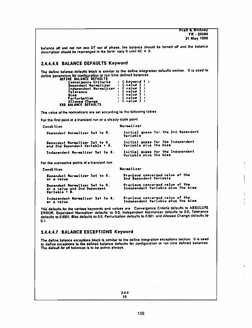
Pratt E WhitneyFR - 20284
31 May 1990
balance off and sol run one OT out o/ phase, the balance should be turned off and Ihe balancedescription should be rearranged in the to_m: vary X until XC = X.
3.4.4.4.6 BALANCE DEFAULTS Keyword
The define balance de_uns block is similarlo the define iniegratio_de_ults section. , is usedtodefine paramefe_kxconfigurationorrun time defined balances.
D[F;N[ IALANCE DEFAULTSConvergence Criteria ( keyNord ) ;Oependqnt Hormal|zer ( ve|ue ) ;Independent Noremlizer ( value ) ;Te|eean¢e ' ( value ) ;lies ( v,lue } zferturbeticm ( v_|ue ) ;A||owod Chlnge ( value ) ;
END IALANC[ D[FAULTS
The value of the normatizers are set according to the to/lowing tables
FC_ the first I)OJnl in a transient run or a steady-state point_
Condition
Dependent Norullzer Set to 0.
Dependent Norma]izer Set to O.end Znd Dependent Vartab|e s O.
Independent Nornalizer Set to 0.
Fcw lho su¢cess_epoiniso/atransienlrun:
Coal|ties
Dependent NormaI|zer Set to O.or s ve|ue
Dependent Normalizer Set to 0.or a value end 2nd DependentVariable • I.
Independent Norma|izer Set to 0.or a value
Norn.Rlizer
|nLtLa| guess for. the 2rid DependentVariable
Initial guess for the IndependentVariable plus the bias
In/t/el guess for the _ndependentVariable p|us _he bias
Moralizer
Previous converged value of the2rid Dependent Vaeiebla
Previous converged value of theIndependent Variable plus the bias
Previous converged value of theIndependent Variab|e plus the bias
The" defaults for the various keywords and values are Convergence Crileria defaults to ABSOLUTEERROR, Oependent Normalizer defaults to 0.0. Independent No, realizer defaults to 00. Tolerancedefaults Io 00001, Bias defaults Io 0+0. Perturbation defaults to 0 001. and Allowed Change defaults to0.1.
3.4.4.4.7 BALANCE EXCEPTIONS Keyword
The define balance exceptions block is similar to the define inlegralion exceptions section. It is usedto define exceptlons to the defined balance defaulls for configuration or run time defined balances.The dofauH k_r all balances is to be active always.
3.4,415
136
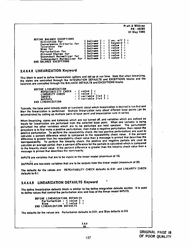
DEFINE BALANCE EXCEPTIONSActivation for ( beZn_-e )Convergence Crlteria for ( b_neme )Tolerance for { bo|n_ee )Bias for ( ba|n_e }Perturbation for ( be|nAme }A||o_ed Change for ( beln_e }Dependent Norma|izer for ( belneae }Independent Noraa|lzer for ( beln_e )
END |ALAHCE EXCEPTIONS
Pralt &WhitneyFR -20284
31 May t990
{ on, off } J( keyk_ord } ;( velue ) ;( veaue ) ;( velue ) ;( velue }{ v.luf ) ;( velue } ;
3.4.4.4.8 LINEARIZATION Key word
This block is used to define linearization options and set-up at run time. Hole that when linearizing.the slates are conlro/led through the INTEGRATION DEFAULTS and EXCEPTIONS blocks and Ihebalances are Controlled through the BALANCE DEFAULTS and EXCEPTIONS blocks.
DEFINE LINEARZZATIOHREPEATABILITY CHEC[ t { value } !L[NEARITY CHECK t { value ) ;|NPUTS t ( v4e|ab]e |fst ) ;OUTPUTS I ( verfeble Its( } !
END LZHEARIZATION
Typically. the base point (steady-slate or transienl} abou! which linearizatic,_ is desired is run firs( end_en the linearizal_n is performed Multiple linearization runs about different base poinls can beaccomplished by seHing up mulliple pairs _ base point and linearlzalion runs in series.
When lineartzing, stales and balances which are not lurned off'. and variables which are defined asinputs for linearization are perturbed from the selected base point. When one variable is beingperturbed Ihe olher variables which are to be perturbed are held constan¢. The perturbationI:¢ocedure is to firm make a posilive perlurbalion, then make a negative perlurbalion, then repeal Ihepositive perturbalion. To perform the repealabilily check, the two positive perturballons are used tocah:ulale a percen! difference which is compared Io the repeatability check value. If the percentdifference is greater than the repealabilily check value then a message is printed thai describes thenoftrepealabillty. To perform the linearily check, lhe positive and negative partials are used tocalculate an average partial, then a percenl difference for the partials is calculated which is comparedIo the linearily check value I! Ihe percenl difference is grealer than Ihe linearily check value then •message is prinled thai describes the nonhnearity,
INPUTS are variables that are Io be inpuls Io the linear model (maximum of 15)
OUTPUTS are non-stale variables that ere to be oulpuls from the linear model (maximum of 20}
The defaults for the values are" REPEATABILITY CHECK de[aults to 0Ot. and LINEARITY CHECKdefaults Io 0.t.
3.4,4.4.9 LINEARIZATION DEFAULTS Keyword "
The detlne linearlzaiion defaults block is similar to the define tnlegralion defaults section. II is used!o define values thai conlrol Ihe perlurbation size and bias of the linear model INPUTS.
DEFINE LINEARIZATION DEFAULTSPerturbation , ( value } ;lisa , ( velue ) ;
END LZNEARIZAT|ON DEFAULTS
The defaults for the values are: Perlurbalion defaults to 0.0t. and Bias defaults to 0.0.
.1.4.4I_
137ORIGINAL PAGE ISOF POOR QUALITY
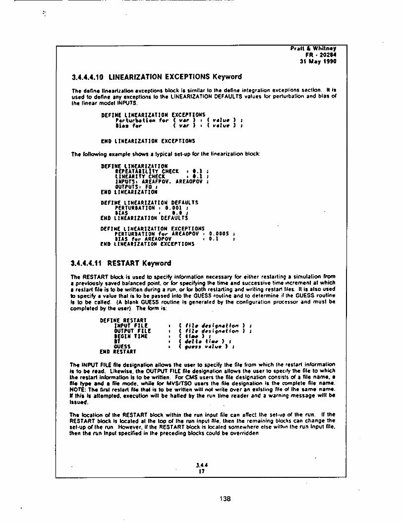
Pratt & WhitneyFR - 20284
31 May 1990
3.4.4.4.10 BNEARIZATION EXCEPTIONS Keyword
The define linearization exceptions block is similar to the define integralion excepl;ons section. It isused Io define any exceptions to the LINEARIZATION OEFAULTS values for perlurbalion and bias o(the linear model INPUTS.
DEFINE LINEARIZATIOH EXCEPTIONSPerturbation for ( vat } ,JiaS for ( vat } ,
{ value ) !( v,lue ) J
END L|NEARIZATION EXCEPT.IONS
The folh_ving example shows a typical set-up for Ihe linearizalion block:
DEFINE LIN[ARIZATZONtEPEATAIILITY CHECK , 0.1 ;LINEARITY CHECK , O.I ;INPUTS, AREAFPOV. AREAOPOV ;OUTPUTS, FO ;
END LINEARIZATION
DEFIN( LIHEARIZATIOH DEFAULTSPERTURBATION , 0.001BIAS , 0.0 ;
END L[NEARIZATION DEFAULTS
DEFINE LINEARIZATZON EXCEPTIONSPERTURBATION for AREAOPOV , 0.0005 ;IIAS for AREAOPOV = 0.1 ;
END LINEARIZATION EXCEPTIONS
3.4.4.4.1t RESTART Keyword
The RESTART block is used to specify information necessary for eilher restarting a simulation froma previously saved balanced point, or for specifying the time and successive time increment at which8 restart file is to be written during a run. or for both restarting and wriling restart 6los It is also usedto specify a value lhat is to be passed into the GUESS routine and Io delermine if the GUESS routineIs to be called. (A blank GUESS routine is generated by the configuration processor and must becompleted by the user). The fo*m is:
DEFINE RESTART|NPUT FILE , ( file d.sfgnatton ) iOUTPUT FILE , ( file designation ) ;8EGIN TIME , ( time } ;DT , ( dell, Cime } !GUESS , ( #uess v,lue ) I
END RESTART
The INPUT FILE file designation allows the user to specify the file from which the reslarl iniormationis to be read. Likewise. the OUTPUT FILE file designation allows the user to spec_h/the file to whichthe restart information is to be wrillen. For CMS users the file designation consisls o( a file name. •file type and 8 file mode. while for MVSITSO users Ihe file designation ts the complete file name.NOTE: The first restart file that is to be wriflen will no( write over an existing file at' Ihe same name.If this Is attempted, execution will be halted by the rvn lime reader and a warning message will beIssued.
The location o( the RESTART block within the run input file can affect Ihe set-up of the run. If theRESTART block is located at Ihe too of the run input file. then Ihe remaining blocks can change theset-up o( the run However. if the RESTART block is Iocaled somewhere else within the run input file.then the run input specified in the preceding blocks could be overridden
3.4.4I?
138
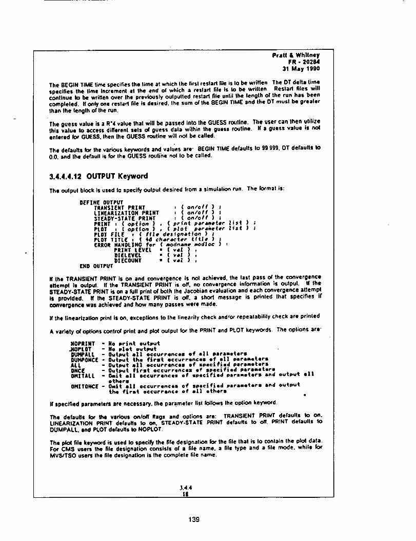
Pratt & WhllneyFR - 20284
:$1 May 1990
The BEGIN TIME time specifies the time at which the first restart file is Io be written The DT delia timespecifies the lime incremenl at the end of which a reslad hie is to be written Reslarl files willcontinue Io be writlen over the previously outpulled restarl file until the length o/the run has beencompleted. If only one restart file is desired. Ihe sum o(the BEGIN TIME and the OT must be greater|hen Ihe length of Ihe run.
The guess value is a R'4 value lha! will I_ passed into the GUESS routine. The user can then utilizethis value to access dilTerenl se|s o( guess data wilhin the guess routine, if a guess value Is nolentered for GUESS. then the GUESS routine will not be called.
The defaults k_" the various keywords and values are- BEGIN TIME defaults to 9g 999. OT defaults to0.0. and the default is for the GUESS routine nol Io be called.
3.4.4.4.12 OUTPUT Keyword
The output block is used to specify Output desired from a simulation run. The formal is:
FIEFZNE OUTPUTTRANSIENT PRINT , ( on/off } lLIMEARIZATION PRINT , ( on/off } ;STEADY-STATE PRINT : ( on/off ) ;PRINT I ( option ) , ( print p,r_eter list ) ;PLOT , { gotten } , ( p|o_ perd_eter |_s| ) ;PLOT FILE _ ( file desfgnatfon ) ;PLOT TITLE , ( _8 character tt(|e ) ;ERROR HANDLING for ( _dnam, rood|go ) ,
PRINT LEVEL • { veI } ,DIELEVEL = { va! } ,DIECOUNT " (val } ,
END OUTPUT
If the TRAHSIENT PRINT is on and convergence is not achieved. Ihe las! pass OF the converoenceatteml_ is Output. If the TRANSIENT PRINT is off. no convergence information is output. II theSTEAOY-STATE PRINT is on a full print OFboth the Jacobian evaluation and each convergence attempthi provided. If lhe STEAOY-STATE PRINT is o/i" a short message is printed Ihat specifies I(convergence was achieved and how many passes were made.
If the linearization print is on. exceptions Io Ihe linearity check andPor repeatability check are printed
A variety OFoptions control print and plot outpul for the PRINT and PLOT keywords The oplions are-
NOPRZNT - No print outputJiOPLOT - No plot outputDUtqPALL - Output all occurrences of ill paranetersDUHPONCE - Output the first occurrences of all parametersALL - Output eli occurrences of soe¢tfled parametersONCE - Out_t f|rst occurrences of specified parametersOIqITALL - Omit el| occurrences of specified parameters end output oil
othersOHITONCE * Omit el| occurrences of spat|tied parameters end output
the first eccurrence of e|| others
If specified paramete_ are necessa_, the parameter lisl follows the option key'word
The defaulls for the various on/o# flags and options are: TRANSIENT PRINT defaults to on.LINEARIZATION PRINT defaults Io on. STEAOY-STATE PRINT defaults to off. PRINT defaults toOUMPALL. and PLOT de(multi Io NOPLOT.
The plot file keyword is used to specify the file designation for the file thai is to conlain the plot data.For CMS users the file designation consists of a file name. a file type and a file mode. white forMVS/TSO users the file designation is Ihe complete file name.
,3,4.4I$
139
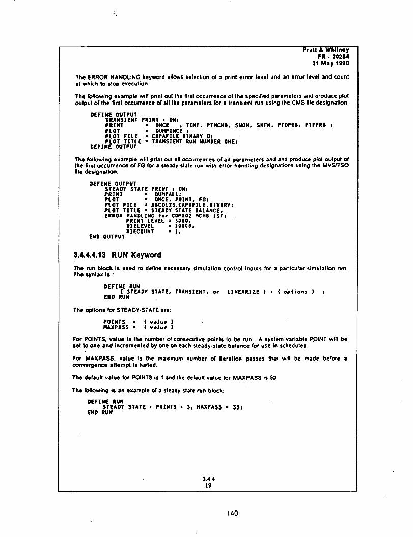
-°
Pratt & WhitneyFR - 20284
31 May 1990
The ERROR HANOLING key'word allows selection of a print error level and an errc_r level and countal which Io stop execution
The following example will prinl out the first occurrence or the specified paramelers and produce plotoutpul of the firs! occurrence of all the parameters for a Iransienl run using the CMS file designation
DEFINE OUTPUTTRANSIENT PRINT , ON;PRINT = ONCE , TIME, PTHCHB, SNOH, SNFH, PTOPRB, PTFPRB !PLOT • DUHPONCE ;PLOT FILE : CAPAFiLE |INARY DlPLOT TITLE • TRANSIENT RUN NUMBER ONE;
DEFINE OUTPUT
The following example will print out all occurrences of all parameters and and produce p_l outp_ oflhe flrs4 occurrence of FG for a steady-state run with error handling designations using the MVS/I"SOfile designalk:m.
DEF|NE OUTPUTSTEADY STATE PRINT , ON;PRINT • BUMPALL;PLOT : ONCE, POINT, FG;PLOT FiLE = AICD|Z$.CAPAFiLE.|INARY;PLOT TITLE = STEADY STATE |ALANCE;ERROR HANDLING for COMB02 HCH| |ST;
PRZNT LEVEL = 3000,DIELEVEL s 10000.DIECOUNT : 1,
END OUTPUT
3.4.4.4.13 RUN Keyword
The run block is used Io define necessary simulation control inputs for a parltcular simulation run.The tynlax is :
DEFINE RUN( STEADY STATE, TRANSIENT, or
END RUNLINEARIZE ) , { options ) ;
The oplions for STEADY-STATE are:
POINTS • ( ve|ue }IqAXPASS = ( velue }
For POINTS. value is the number cA consecutive points Io be run A system variable .POINT will besel Io one and incremented by one on each steady-state balance for use in schedules.
For MAXPAS5. value is the maximum number of iteration passes thai win be made before aconvergence allempl is hailed
The default value k:,r POINTS is I and the default value for MAXPASS is 50
The following IS an example of a steady-slate run block.
DEFINE RUNSTEADY STATE : POINTS • $, MAXPASS • 35;
END RUN
3.4.419
140
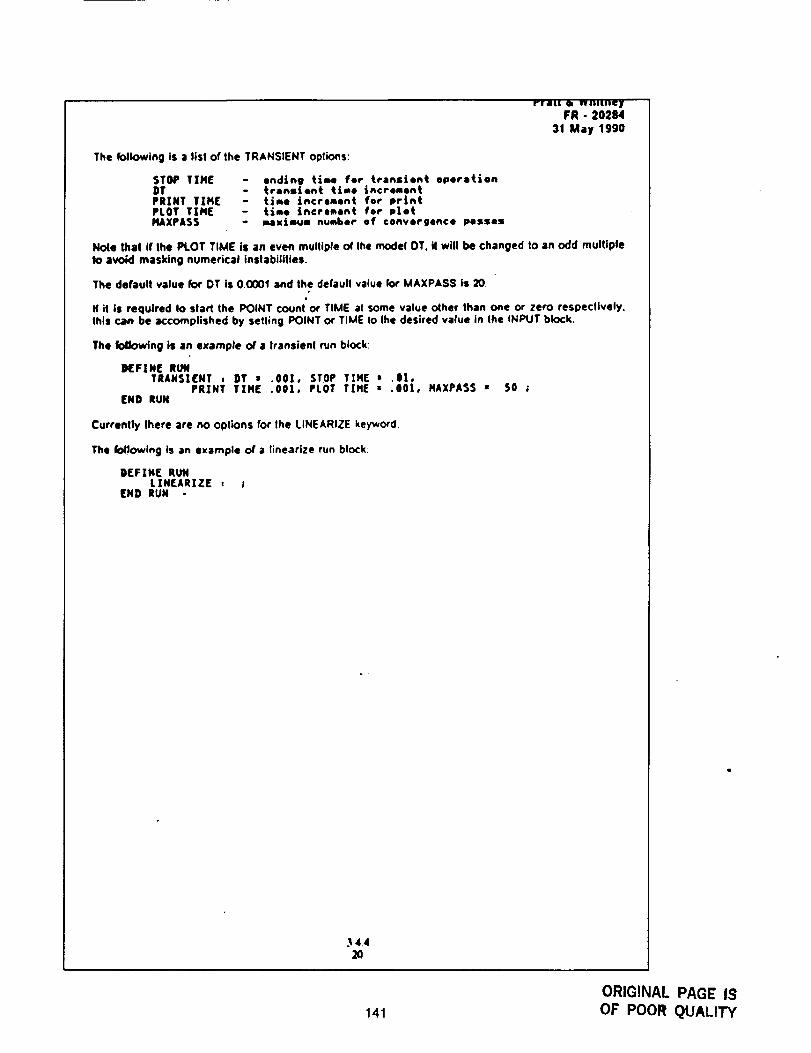
I'IiUl II WHIInC|
FR o 20284
31 May 1990
The following is a lisl of the TRANSIENT oplions:
STOP TIMEDTPRINT TINEPLOT TIMENAXPASS
- ending time for transient operation- transient tlmo increment- time increment for print- time increment for p|ot- msximum number of convergence pesses
Nolo lhal If Ihe PLOT TIME is an even multiple of Ihe model DT. il will be changed to an odd multiple1o avoid masking numerical inslabililies.
The default value for OT is 0.0001 and the defaul! value for MAXPASS is 20.w
N it is required Io start the POINT counl or TIME al some value other than one or zero respectively.this can be accomplished by setting POINT or TIME to Ihe desired value in the INPUT block,
The following is an example of a Iransien! run block:
KFINE RUNTRANSIENT , DT • .00|, STOP TZNE # .8|,
PRINT TIN[ .001, PLOT T|NE • .00|,END RUN
NAXPASS " S0 ;
Currently lhere are no oplions for Ihe LINEARIZE keyword.
The foJ!owing ts an example o( a linearize run block:
D[FIHE RUNLINEARIZE * t
END RUN
.1.4.4
141
ORIGINAL PAGE IS
OF POOR QUALITY
Pratt & WhitneyFR - 20284
31 May t990
3.4.4.5 Building a Module
A FORTRAN subroutine can easily be converted to Ihe ROCETS syslem.be included in the system module
The following sections must
t. Subroutine czll list
2. Interface section
3. Hislory oflhe module including author and dated list of revisions
4. Listing of all subroutines and commons required by the module
Informati¢_ required Io inlerface a module into Ihe ROCEI"S system will be conlained in commentcards within the prologue of the module The interface seclion will be in three parts
.
.
Interface informationXlIEGIM INTERFACE ( Nodule Nvme )xl[NO INTERFACE ( Nodule N.ae)
Keywordinformationx|EGIN KEYNORDS ( Nodule Name)XEND KEYNORDS ( Nodule Name )
UnitsinformationxBEG|N UNITS { Nodule Name }x[ND UNITS ( Nodule Name}
3.4.4.S.t Module Communication
Modules may only communicate Io Ihe ROCETS syslem through Ihe subrouhne call lisl of Ihe moduleCo¢_rnons cannot be used to communicate with the main Or other modules However. common blocks
may be used in certain cases for communication belween a module and a sub-module
3.4.4.S.2 Interface Data Section
The interface data section of Ihe module allows the configuralion processo_ to creale thecommunication link with lhe ROCETS system Specific slandards for the interface seclion of modulesfofk)w:
**" INTERFACE BLOCK "'"
The inlerface block relates call list names Io system names, defines lhe slaius of each variable for
system ooeralion, defines the I10 slalus of each variable, and the FORTRAN variable type The set-upconsists of $ pieces of information for each variable:
1. Call list name
2. System name
3,4.421
142
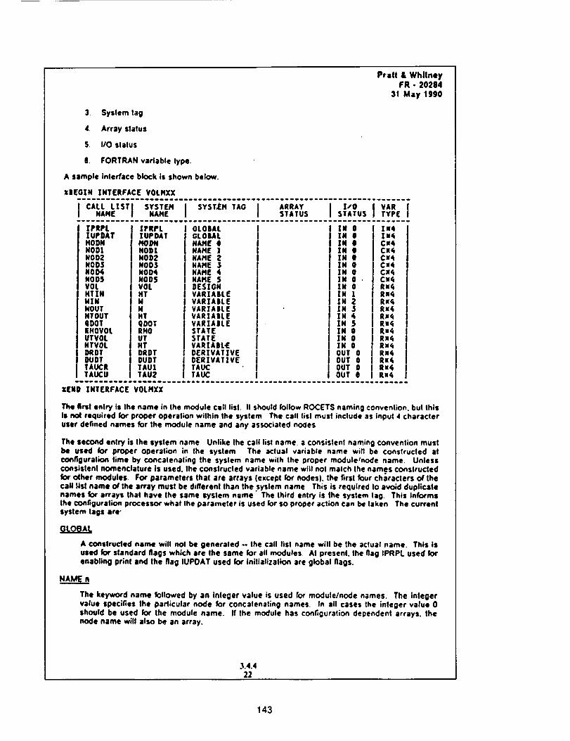
Pratt & WhllneyFR - 20284
31 May lgg0
3, System tag
4. Array status
S. IIO slalus
8. FORTRAN variable type,
A sample interface block is shown below.
XlEOZN ZNTERFACE V0LHXXuueaumeeeaeuneeeeqee eeeeaeeeeeeeee_m at aeon ee eeee e e aloe ew ueene e aaaeeee
][PRPLZUPDATMODNNOD1NOD2NODSNOD4NOD5VOLHT ! NHZHHOUTHTOUTQDOTEHOVOLUTVGLNTVOLDROTDUDTTAUCRTAUCU
|PRPLIUPDATHODNNO0|NOD2NODSNOD4NOD5VOLNTHNNTQDOTRHOUTHTDRDTDUDTTAU|TAU2
GLOBALGLOBALN/dIE ¢1NAME ]NAME 2NAME 3NAME 4NAME $DE-_|GNVARZABLEVARIAIILEVARIAllL[VARtA|L[VARXABLESTATESTATEVARZA|L-EDER[VATZVEDER][VATZ VETAUCTAUC
IN 0IN OIN OIN 0IN OIN OIN 0IN 0IN 0IN 1IN 2IN $ININ SIN 0IN 0IN 0OUT 0OUT 0OUT 0OUT 0
teetxqCa4CxqCx¢CueCx¢Cx¢RueRx4RxqRx¢RueR_4
Rx¢Rn,tRueRx4
Rue
ZENB INTERFACE VOLMXX
The flrsl entry is Ihe name in the module Cull list. It should follow ROCETS naming convention, but thisis no4 required for proper operation wilhin Ihe system The call list must include as input 4 characteruser defined names for the module name and any associatecl nodes
The second entry is Ihe system name Unlike Ihe call list name. a consislenl naming convention mustbe used for proper operation in the system The actual variable name will be constructed atconfiguralion time by concalenaling the syslem name with Ihe proper module/node name Unlessconsistent nomenclature is used. Ihe conslrucled variable name will not malch the names constructedfor ceher modules For paramelers thai are arrays {except for nodes), the first four characters ot thecall list name of the array must be different than the system name This is required Io avoid duplicatenames for arrays that have the same system name The third entry is the system lag. This Informsthe configuration processor what Ihe parameter is used for so proper action can be taken The currentSystem lags are'
A co_slruded name will nol be generated - the call list name will be the aclual name. This isused for standard flags which are the same for all modules At present, the flag IPRPL used forenabling print and the flag IUPOAT used for inilialization are global flags.
The keyword name followed by an integer value is used for module/node names. The integervalue specifies Ihe particular node for concatenating names. In all cases Ihe integer value 0should be used for the module name. If the module has configuralion decendenl arrays, thenode name will also be an array.
.1.4.422
143
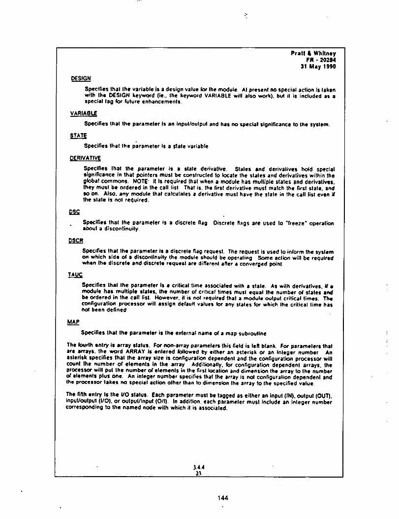
Pratl& WhitneyFR- 20284
31May1990DESIGN
Specifiesthatthevariableisa design value fox the module. At presenl no special action iS lakenwith the DESIGN keyword tie., the keyword VARIABLE wilt also work), but il is included as aspecial lag for fulure enhancements.
VARIABL E
Specifies thai the parameter is an inpulloulput and has no special •lgnlficance 1o the system.
STATE
Specifies thai the parameter is a l;lale variable.
DERIVATIVE
Specifies Ihat Ihe parameler is a state derivalive. Stales and derivatives hold specialsignificance in that pointer• musl be constructed lo locale the states and derivatives wilhin theglobal commons. NOTE" it is required thai when a module has multiple stales and derivatives.they must be ordered in the call list That is, Ihe first derivative must match the tarsi slate, andsO on. Also. any module thai calculates a derivative musl have lhe slate in the call list even ifthe state Is nol required.
0so
Specifies thal the parameter is a discrete flagabout a discontinuity
Discrete flags are used to "freeze" operation
0scR
Specifies that Ihe parameter is a discrele flag requesl. The request is used 1o inform the systemon which side of a discontinuily the module should be operaling Some action will be requiredwhen the discrete and discrete requesl are different aller a converged point
T,uc
Specifies thai the parameter is a critical time associated wilh a stale. As with derivalives, If •module has multiple stales, the number of crihcal times must equal the number of stales andbe ordered in the call lisl. However. it is not required that a module output critical times. Theconfiguration processor will assign default values for any stales for which the critical lime hasno( been defined
ux.___P
Specifies that the parameter is the exlernal name of a map subroutine
The foudh enlry is array •talus. For non-array parameter• this field is tell blank For parameters thatare arrays, the word ARRAY is enlered k)llowed by either an asterisk or an inleger number Anasterisk specifies thai the array size is configuration dependent and the configuration processor willcount the number of elements in the array Additionally. for configuralion dependent arrays, lheprocessor will pul Ihe number of elements in the fatal location and dimension the array to the numberof elemenls plus one. An integer number specifies that the array is nol configuration dependenl andthe processor lakes no special action olher than to dimension the array 1o the specified value
The fifth entry Is the VO status. Each parameter must be tagged as either an input (IN). output (OUT).input/oulpul (I/O). or outpul/inpul (O/I), In addition, each parameter musl include an Inleger numbercorresponding to lhe named node with which it is associaled.
3.4.42.1
144
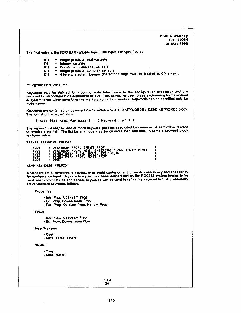
Prall & WhitneyFR - 20284
31 May 1990
The final entry is the FORTRAN variable lype The lypes are specified by'
R*4 : Single precision real variable1"4 : Integer variableR'S = Oouble precision real variableX'8 : Single precision complex variableC'4 - 4 byle character Longer character strings must be treated as C'4 arrays.
• "" KEYWORD BLOCK "'"
Keywo(ds may be defined (or inputting' node Information to the configuration processor and arerequired for all configuralk:m dependent arrays This allows the user io use engineering terms insleado/system terms when specifying the inputs/outputs _or a module Keyw<xds can be specified only k:_node names
Keywords are contained on comment cards wiihln a %BEGIN KEYWOROS / %ENO KEYWOROS blockThe formal ol Ihe keywords is
( cal| lis_ nale for node } : ( key_,rord lfst ) ;
The keyword list may be one o¢ more keyword phrases separaled by commas A semicolon is usedto terminate the list The lisl for any node may be on more Ihan one line A sample keyword blockiS shown below:
_c|EOIN KEYHORD$ VOLNXX
NODI , UPSTREAH PROP, INLET PROPNODZ , UPSTREAH FLOH, HIN, ENTERING FLOH, INLET FLON ;NOD3 : DOHNSTREAH FLON, NOUT, EXIT FLOHNOOA , DOMHSTREAH PROP, EXIT PROP !NODS , gDOT J
XENO REYHORDS VOLHXX
A Standard set o( key"words is necessary to avoid confusion and promote consistency and readabilityIo4' configuration inpul. A preliminary set has been defined and as the ROCETS system begins to beused. user comments on appropriate keywords will be used to refine the keyword list A prelim;naryset o( standard keywords follows:
Properties:
- Inlet Prop. Upstream Prop- Exit ProD. Oownslream Prop- Fuel Prop, Oxidizer Prop. Helium Prop
Flows:
- Inlel Flow. Upstream Flow- Exit Flow. Oownstream Flow
Neat Transfer:
- (=dOt- Metal Temp. Tmetal
Shafts:
- Torq. Shaft. Rotor
3.4.424
145
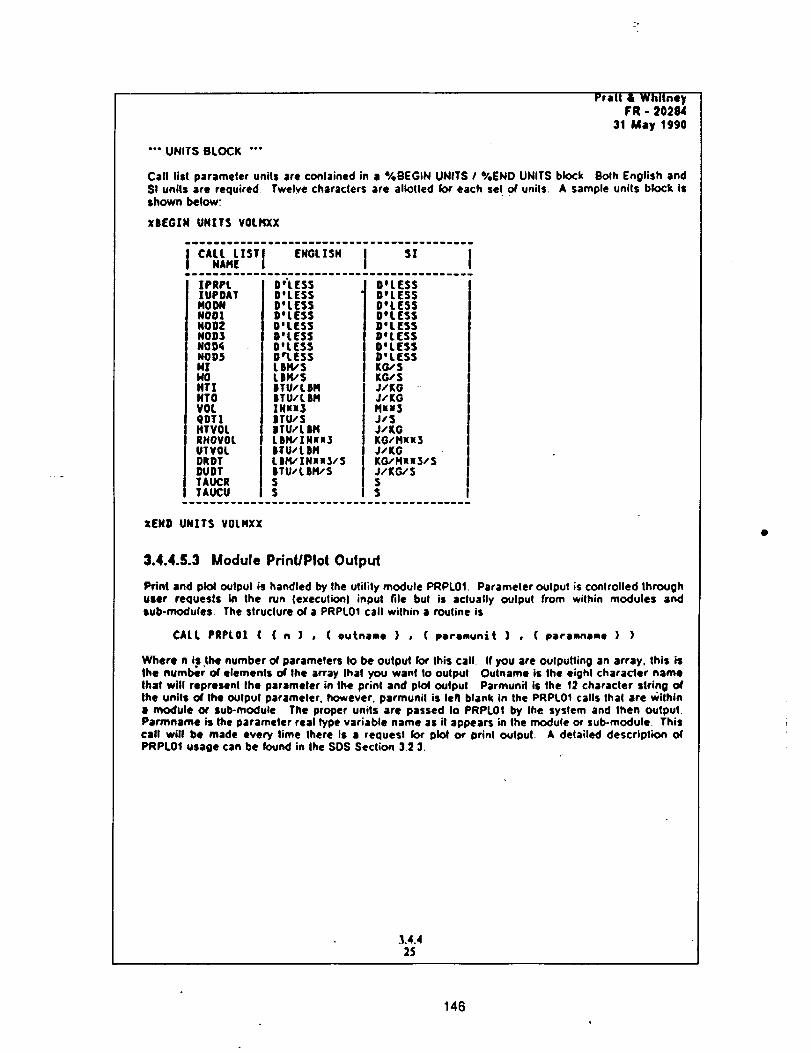
Pratt&WhitneyFR- 20284
31 May 199(]
"'* UNITS BLOCK "'"
Call list par•meier units are conlained in • %BEGIN UNITS 1%ENO UNITS block Bolh English andSt units are required Twelve characters are alk:)Ued for each set o( unils A sample units block isshown below:
XBEGZN UNITS VOLHXX
.,.,. I " IZPRPLIUPDATMODNNODZNOOZNOD3NOD_NO0$N!HONTIHTOVOLqDTIHTVOLRHOVOLUTVOLDRDTDUDTTAUCRTAUCU
DwLESSD'LESSD'LESSD'LESSD'LESSB'LES$D'LESSDrl.ES5LBIe/SL|M/SiTU/LBHiTU/LBHINnS|TU/S|TU/LSHLBiq/INuu3ITU/L|MLBl't/INxuS/S|TU/LBH/SSS
D°LESSDeLESSD'LES5g'LESSD'LESSDeLESSD'LESSD'LESSKG/SKG/SJ/KOJ/KGHuu3Jl$J/KOKG/Mxl3J/KGKG/MII3/SJ/KG/SSS
XENO UNITS VOLMXX
3.4.4.S.3 Module PrinUPlot Output
Prim and plol output is handled by the utilily module PRPL0t Parameler output is conlrolled throughuser requests in the run (execution) input file buI is actually oulput from wilhin modules andtub-modules The slruclure of a PRPL01 call within a routine is
CALL PRPL0| ( ( n ] , ( outname ) , ( paramunlt } , ( paramname ) )
Where n t.sthe number of parameters to be oulput rot Ihis call If you •re oulputling •n array, this isthe number of elements of the array Ihat you wanl |o output Outname is the eight char•tier nameIhaf will represent Ihe parameter in the print and plot output Parmunil is Ihe 12 character string ofthe units Of the output par•meier, however, parmunil is left blank in the PRPL0t calls thai are within• module ot sub-module The proper units are passed Io PRPL0! by the system and then outpul.PaTron•me is the parameter real type variable name as it appears in the modulo or sub-module. Thiscall will be made every lime there is a requesl for plot o4"prinl output. A dela;led description oTPRPL01 usage can be found in the SDS Section 32 3.
.1.4.425
146
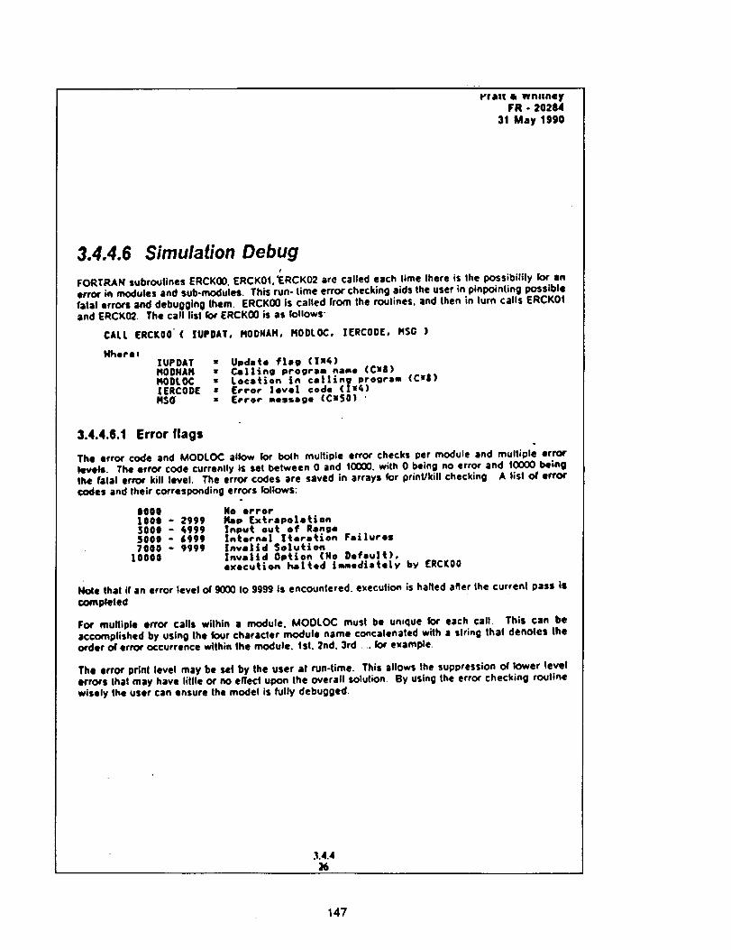
I-r&I! 4k WhlIgtey
FR - 2O284
31 May 1990
3.4.4.6 Simulation DebugI
FORTRAN subroutines ERCK00. ERCK01.'ERCK02 are called each lime there is Ihe possibility for an
error in modules and sub-modules. This run- time error checking aids the user in pinpointing possible
fatal errors and debugging them. ERCK00 is called from the routines, and then in turn calls ERCKOtand ERCK02 The call Ilsl for ERCK00 is as lollows_
CALL [RCKO0"( IUPDAT, HODHAN, HODLOC, IERCOOE, HSG )
Nhere,
XUPDAT • Update flag ([n_)HODNAH • Calling program name (till)140DLOC • Lo©etion in calling program (Cll|)IERCODE • [rror level code (IMP)H$_ • [rror message (Cx50) '
3.4.4.6.1 Error flags
The error code and MOOLOC allow for bo4h multiple error checks per module and multiple error
levels. The error code currenlty is set between 0 and tO000, with 0 being no error and 10000 being
the fatal error kill level. The error codes are saved in arrays for print/kill checking A list of error
codes and their corresponding errors follows:
8000 He errorIO00 - 2999 /_p (xtrapo|etien3000 - _999 Input out of Range5000 - 4999 Internal Iteration Failures7000 - 9999
10000Invalid SolutionInvalid Option (Ha Default),execution halted tmmedlately by ERCK00
Note that if an error level o4"9000 to gggg is encounlered, e_eculior_ is hailed after the current pass is
completed
For multiple error calls within a module. MOOLOC must be un,que for each call. This can be
accomplished by using the four character module name concatenated with a siring thai denotes the
order o4' error occurrence within the module. 1st. 2nd. 3rd .... k_r example
The error prinl level may be set by the user at run-time. This allows the suppression or lower level
errors thai may have little or no effec/upon the overall solution By using the error checking routine
wisely the user can ensure the model is fully debugged.
.'t.4.4
147
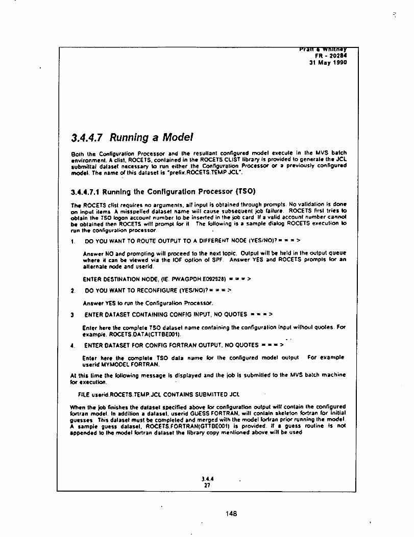
_'ra, • wnimeyFR - 20284
31 May 1990
3.4.4.7 Running a Model
Both the Configuration Processor and the resultant configured model execute in the MVS batchenvironment. A clist, ROCETS, contained in the ROCETS CLIST library is provided 1o generate the JCLsubmittal dalaset necessary to run either the Configuration Processor o4" a previously configuredmodel. The name 04'Ihis dalaset is "prefix.ROCETS.TEMP JCL'.
3.4.4,7.1 Running the Configuration Processor (TSO)
The ROCETS clisl requires no arguments, all input is obtained through prompts NO validation is doneon Input items A misspelled datase! name will cause subsequenl job failure ROCETS first tries toobtain the TSO Iogon account number Io be inseded in the job card Ifa valid account number cannotbe obtained then ROCETS wilt prompl (or it The following is • sample dialog ROCETS execution torun the configuralion processor
I. DO YOU WANT TO ROUTE OUTPUT TO A DIFFERENT NODE (YES/NO)? = := = >
Answer NO and prompting will proceed to the next topic. Output will be held in the oulput queuewhere it can be viewed via the IOF option of SPF Answer YES and ROCETS prompls for analternate node and userid.
ENTER DESTINATION NODE. (IE I:NNAGPDH E092928) - : = •
2 00 YOU WANT TO RECONFIGURE (YES/NO)? = = = •
Answer YES Io run the Configuralion Processor.
3 ENTER DATASET CONTAINING CONFtG iNPUT. NO QUOTES = = =' •
Enter here the complete TSO dataset name containing the configuralion input wilhout quotes For
example. ROCETS.OATA(CTTBE001 ).° .
4. ENTER OATASET FOR CONFIG FORTRAN OUTPUT, NO QUOTES "= " = •
Enter here the COmplele TSO dais name for Ihe configured model output For exampleuserid MYMODEL FORTRAN.
At this time the following message is displayed and Ihe job ts submilled to the MVS batch machinefor execution.
FILE userid.ROCETS.TEMPJCL CONTAINS SUBMITTED JCL
When the job finishes the dalaset specified above for configuration output will contain the configuredfortran model In addilion a dalasel, userid GUESS FORTRAN. will conlain skeleton fodran for initial
guesses This dalaset must be completed and merged with the model fodran prior" running the model.A sample guess datasel. ROCETS.FORTRAN(GTTBE00t) is provided. If s guess routine is no(appended to the model fortran datasel the library copy menlioned above wilt be used
].4.427
148
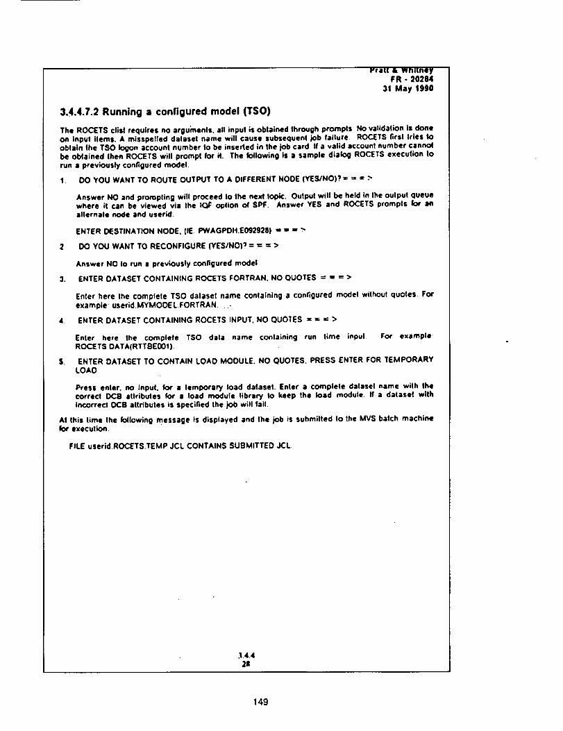
rral! & Wnl[neyFR - 20284
31 May 1990
3..4.4.7.2 Running a configured model (TSO)
The ROCETS clisl requires no arguments, all input is obtained through prompts No validation is doneon inpu( items. A misspelled dataset name wilt cause subsequent job failure ROCETS first tries toobtain the TSO Iogon account number to be inserted in the job card If a valid account number cannotbe oblained then RC)CETS will prompt for it. The following is a sample dialog ROCETS execution torun a previously configured model.
1. 00 YOU WANT TO ROUTE OUTPUT TO A DIFFERENT NODE (YES/NO)? = =, = >
Answer NO and prompting will proceed to the next Iopic. Output will be held in the oulpul queuewhere it can be viewed via Ihe ICIF option of SPF. Answer YES and ROCETS prompls for anallernale node and userld.
ENTER DESTINATION NODE. tIE PWAGPOH.E092928) ,s I, ,,w.--
2 IX) YOU WANT TO RECONFIGURE (YES/NO)? = = = >
Answer NO IO run s previously configured model
3. ENTER OATASET CONTAINING ROCETS FORTRAN. NO QUOTES = : : >
Enter here Ihe complele TSO dalaset name containing a configured model without quotes. Forexample userid.MYMOOE L.FORTRAN -
4 ENTER DATASET CONTAINING ROCETS INPUT. NO QUOTES = = ,= >
Enler here Ihe complete TSO dale name containing run lime input For example:ROCE TS DATA(RTTBE00t).
$. ENTER DATASET TO CONTAIN LOAD MODULE. NO QUOTES, PRESS ENTER FOR TEMPORARYLOAD
Press enter, no input, for a temporary load dataset. Enter a complete dalasel name wilh thecorrect PC8 attributes for a load module library to keep Ihe load module. If a dataset withincorrect 0C8 attributes is specified the job will fail
At this lime Ihe following message is displayed and the job is submitted to the MVS batch machineexecution.
FILE userid.ROCETS.TEMP JCL CONTAINS SUBMITTED JCL.
3.4.4211
149

Thispagewasintentionallyleft blank.
150
-o
Appendix BExample Pump Module
A FORTRAN code listing of a Pump Module (PUMP01) and the engineering documentation ispresented as an example, all of the engineering modules, sub-modules, and utilities are containedin the SDS, P&W FR-20284 (Reference 4).
151 PRECEDING PAGE BLANK NOT FILMED
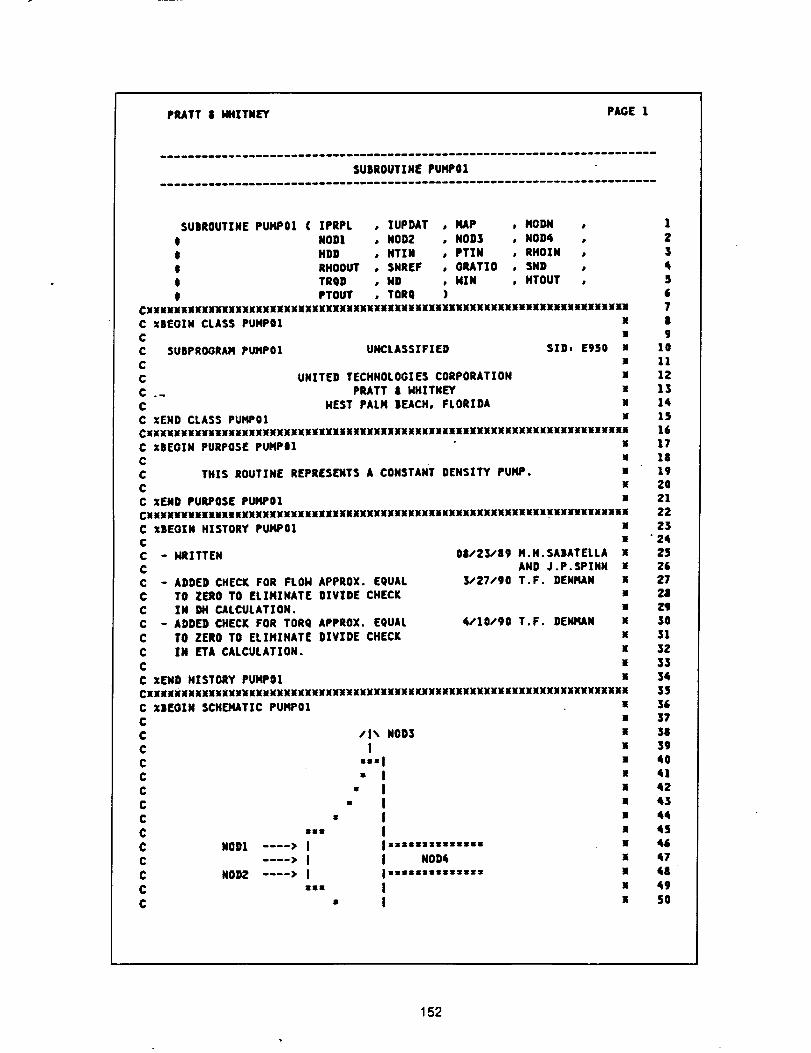
PRATT 1t klHITNEY PAGE 1
SUBROUTINE PUMP01
C xBEOIN CLASS PUMP01CC SUBPROGRAM PUHP01
CC
CC XEND CLASS PUMP01
SUBROUTINE PUMP01 ( XPRPL o IUPDAT , HAP , MODN ,t NOD1 , NOD2 , NOD3 , NOD4 ,
$ HDD , HTIN , PTZN , RHOIN ,$ RHOOUT , SNREF , GRATIO , SND ,t TRQD , MD , HIM , HTOUT ,
0 PTOUT , TORQ )CXNMNNMNMMBMMMMMXMNMNMXMXMKMMNMMMMMNMKMMMMMMMKMNMMMXMNNMMNMMMMMMMMMMMMM
M
M
UNCLASSIFIED SID, Egso uN
UNITED TECHHOLOGZES CORPORATIOH xPRATT & MHZTNEY x
HEST PALM BEACH, FLORIDA zM
CXXXUUXxxxuxxx_xxxx_xxxxx_xxxxxuxxxxxxxxxxxxxxxxxxxxxxxxxxxxxxxxxxxHx_C xBEGIN PURPOSE PUMPOl x
C uC THIS ROUTINE REPRESENTS A CONSTANT DENSITY PUMP. xC EC xEND PURPOSE PUMP01 u
CXXXxxx_xxuxxxXxXxNxxxxxxxxxxxxxxxuxxxxxxxxxxxxxxxxxuxxuxx_NxnxnxxxxC xBEOIN HISTORY PUMP01 xC xC - NRZTTEN 08/23/89 M.H.SABATELLA xC AND J.P.SPINN xC - ADDED CHECK FOR FLON APPROX. EQUAL _27/90 T.F. DEHHAN x
C TO ZERO TO ELIMINATE DIVIDE CHECK uC IN DH CALCULATION. uC - ADDED CHECK FOR TORQ APPROX. EQUAL 4/10/90 T.F. DENMAN x
C TO ZERO TO ELIMINATE DIVIDE CHECK xC IN ETA CALCULATXON. x
C iC zEND HISTORY PUMP01 x
CXXNNMXNNXXXNXNMNNMNMNNNXNMNMNXNXXXNKXXKKNXXXXXNXXXXMXXXXNXXNXNXXXXXMXM
C XSEOIN SCHO4ATIC PUMP01 x
C uC /1% NOD3 xC I u
C "''1 •C • I xC • I xC • I u
C • I "C "" I l
C NOD1 .... • I I ==:===z======= XC .... • I I NO_ i
C NODE .... • I I =,,,,'='=,•,:: I
C ::= I x
C • I i
1
2
345
678
91011IE
13
15
161718
X9202122
E3" 24
2525E7E|
_J
,5O
313Z
3334
353_37
3839
4041
4E
43
44
45
65
47
48
49
SO
152
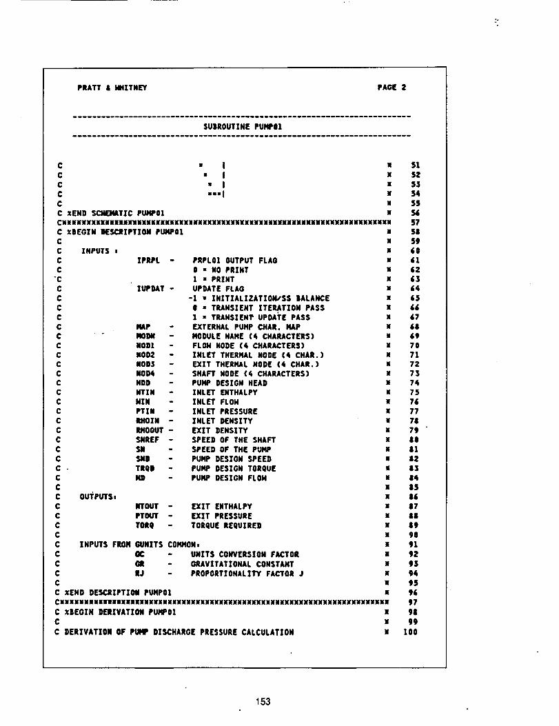
PRATT& HHXTNEY PAGE 2
SUBROUTINE PUMPOI
C • I x
C " I xC • I xC ••'l x
C uC XEND SCMEMATTC PUMPOI xCXXXxxxxxxuxuuxxuxuunnxxxxxxxxxxxxxxxxxxxxxxxxxxxxxxxxxxxxxuxxxxuxxxC XBEGZN INESC_IPTION PUMPO1 xC x
C INPUTS t x
C IPRPL - PRPL01 OUTPUT FLAG HC 0 = NO PRINT i
"C I • PRINTC IUPDAT - UPDATE FLAG x
C -1 • :NXTZALXZATION,'SS BALANCE xC 0 • TILANSIEHT ITERATION PASS xC I • TRANSIENT UPDATE PASS x
¢ MAP - EXTERNAL PUMP CHAR. HAP xC - FIOOM - MODULE NAME (4 CHARACTERS) xC NODI - FLON NODE (4 CHARACTERS) x
C NOD2 - INLET THERMAL NODE (4 CHAR.) xC NODS - EXIT THERMAL NODE (4 CHAR.) xC NOD4 - SHAFT MODE (4 CHARACTERS) xC NOD - PUMP DESIGN HEAD sC HTZN - INLET ENTHALPY
C HIM - INLET FLOH xC PTIN - XNLET PRESSURE x
C IWOIN - INLET DENSITY aC RHOOUT - EXZT DENSITY xC SNREF - SPEED OF THE SHAFT x
C SIl - SPEED OF THE PUMP IC SI4D PUMP DESTON SPEED E
C - TRQD - PUMP DESIGN TORQUE xC 141) - PUMP DESIGN FLOH a¢ aC OUTPUTS_ x
C RTOUT - EXIT ENTHALPY a
C PTOUT - EXXT PRESSURE xC TORQ - TORQUE REQUIRED xC xC INPUTS FROH GUNZTS COMMON= •
C OC - UNITS CONVERSIOH FACTOR x
C (ME - GRAVITATIONAL COHSTANT xC RJ - PROPORTIOHALXTY FACTOR J IC xC XEND DESCRIPTION PUMP01 x
CXUXXUXanUXXXXXXnXXHXUHXXXXXXXXXXXXXMXXXXXXUXXHUXXXXXXUXXXXXXXXXUX
C xBEGZH DERZVATZON PUMP0! xC x
C DERZVATZON OF PUMP DISCHARGE PRESSURE CALCULATION x
51
5Z53
54SS56
57S|59
6061
62636465
67
58697071
72737475
767774
798081
8283
0485D5
878889
90Sl
9293
94959&
97
98
99
100
153
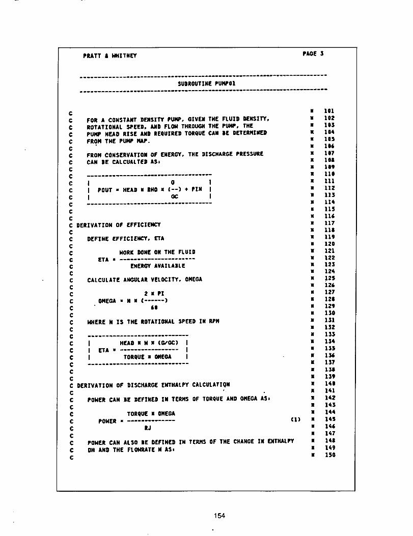
PRATTi Hfl[TN_r PAGE 3
SUiROUTZNE PUHP01
CC
C¢¢
C¢¢C
C
FOR A CONSTANT DENSITY PUMP, GZVEH THE FLUXD DENSITY,
ROTATZONAL SPEED, AND FLON THROUGH THE PUMP, THEPUMP HEAD RISE AND REQUIRED TORQUE CAN |E Dt"rERMINFJFROM THE PUMP NAP.
FROM CONSERVATION OF ENERGY, THE DISCHARGE PRESSURECAN BE CALCUALTED AS:
c I o IC I POUT s HEAD ! RHO X (--) + PZN Ic I oc I
CCC DERZVATZOH OF EFFICIENCY
DEFZNE EFFICIENCY, ETA
HORK DONE OH THE FLUXOETA •
ENERGY AVAZLA|LE
CALCULATE ANGULAR VELOCITY, OMEOA
2 • P!OMEGA • N • ( ...... )
60
HHERE N I$ THE ROTATIONAL SPEED IN RPH
I HEAD X N U (G/OC) II ETA • I
I TORQUEu OMEQA I
POHER CAN IE DEFINED IN TERMS OF TORQUE AND OMEGA AS=
CC
CCCCCC
CCCC
C
CCC
CCC
CC
C
C DERIVATION OF DISCHARGE EHTHALPY CALCULATIONCC
CC TORQUE a OMEGA
C PONER z .....C RJ
C
CC
C
(1)
POHER CAN ALSO BE DEFZNED ZN TER,qS OF THE CHANGE IN EHT_UILPYDH AND THE FLOHRATE N ASI
• 101
• 102• 103
• lOq• lOS• 106
x 107• 108• 109• 110
• 111• llZ• 113
x lldi• 115
M 116w 117• 118• 119
• 120• 121x 122• 123• 12_
• .125x 126• 127• 128x 129
• ISOx 131
• 132
a 133
• 155• 136
• 137• 138
• 139• 160u 1,_1
x 162
1 163• 164• 145
• 146
x 167J,ia
a 1_9x 150
154
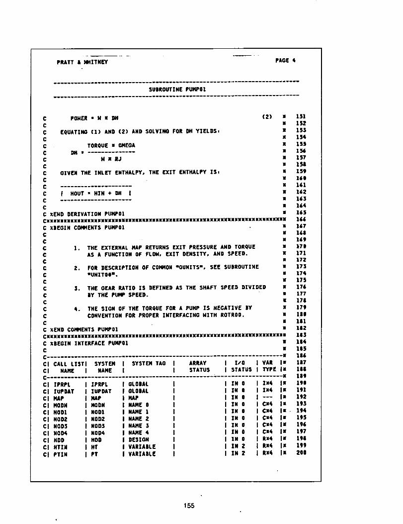
PRATT & HH][TNEY PAGE 4
SUBROUTINE PUMP01
C POldER • M II 9H (2) I
C isC EQUATING (1) AND (2) AND SOLVINO FOR DM YIELDS, •C •
C TORQUE I OMEGA •C DH= •C HINJ •C •
C GIVEN THE TNLET ENTHALPY, THE _%T ENTHALPY IS, •C •C H
C J HOUT • HXN + OH I •C ]lC •
C XEND DERIVATION PUMP01 •CNNNNNNINNNNNINNNNNINNNMNNNNNIIIINNNINNENNNNNNNMNNNNNNNNXNNNKNKNNMNNNNM
C X|EGZN COMMENTS PUMP01 •C •
C •C 1. •C •C mC 2. •C •
CC 3. •C •
C •C _. a
C nC xC XEND COMMENTS PUI'IP01 •
CXXXxxxxxxxxxxxxaxxxxxxxxxxxxxxxxxxxxxxxxxxxxxxxxxxxxxxxxxxxxxxxxxxxxu•C xBEGZN INTERFACE PUMPO| sC w
C-- •
THE EXTERNAL HAP RETURNS EXIT PRESSURE AND TORQUEAS A FUNCTION OF FLOId, EX%T DENSZTY, AND SPEED.
FOR DESCRIPTION OF COMMON mOUNXTS u, SEE SUBROUTINEmUNIT00U.
THE GEAR RATIO %S DEFINED AS THE SHAFT SPEED DIVIDEDIY THE PUMP SPEED.
THE SXGN OF THE TORQUE FOR A PUMP IS NEGAT;VE SYCONVENTION FOR PROPER INTERFACING NITH ROTRO0.
151
152153
154155156157
158159
160161162
163164
165166167168169
170
171172173174
175176177178
179118
181182183
184185
186
Cl CALL LISTI SYSTEMCl NAME I NAME
I SYSTEM TAO I ARRAY I I/0 I VAR Ix 187I I STATUS I STATUS I TYPE Ix 188
• 189
Cl XPRPLCl XUPDAT
Cl PAP
Cl MOONCl NOD1Cl NOD2
Cl NOD3
Cl NOD4Cl NOD
Cl HTZN
CI PTIN
TPRPL
%UPDATPAP
MODNNOD1
NOD2NOD3
NOD4HOD
HT
PT
OLOIALOLOIAL
HAPNAME 0NAME 1
NAME Z
NAME $NAME A
DESIGN
VARIABLEVAR%A|LE
ZN 0IN 0
IN 0TN 0
%N 0IN 0
IN 0IN 0
IN 0
IN 2IN 2
Z_ Is 190II4 l• 191--- Ix 192
Ca4 Ix 193¢x4 In. 194
CX_ Ix 195CX4 Is 196
Cx4 J• 197RX4 J• 198
Rx¢ Ix 119
Rx4 I• 200
155
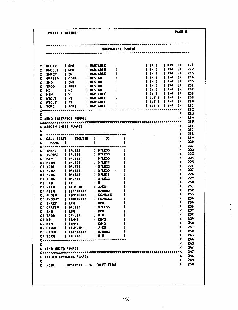
PRATTJ MHITNEY PAGE 5
SUIROUTINE PUMP0|
Ci RHOIN I RNO I VARZA|LE
CI RHOOUT I RHO I VARXAJLE
CJ SNREF | SN J VARIABLECI GRATXO J GEAR. | DES|GN
CI SND J SND | DESIGNCI TRQD I TRQB J DESIGN
Cl MD I MD I DESIGNCJ HIN I N I VARIABLECI NTOUT I NT I VARIABLECI PTOUT | PT J VARIAJLE
C| TORQ ( TORQ | VARIABLE
C
C •END INTERFACE PUMP01
J IN Z Ru4 xI IN 3 Rx4 x
I ZN 4 Rx4 •J IN 0 Rx4 EJ IN 0 Rx4 x
I IN 0 Rx4 uI IN O Rx4 •I IN I Rx4 xJ OUT 3 Ru4 x
I OUT 3 Rx4 xI OUT 0 Rx4 •
CMNMM•MMKNNHMMMNHNMHNMNNMNMXNMMMNMMMMMKMMMMKKXKMNMMMMKNKMNXXIMNXMXMKMXNC X|EOIN UNITS PUMPOIC
CI CALL LISTI ENGLISH
CJ NAHE i
Ci ZPRPL I DeLESSCI ZUPDAT J D°LESSCJ HAP J D%ESS
CJ NODN i D°LESSC| HOD| i. D'LESSC| NOD2 I D'LESSCI NOD3 I D'LESS
C| NOD4 I B'LESSCI NDD I IN
CI HTIN J BTU/LBMC| PTJN " J LJF/IN_x2
CI RHOXN J LM_'IN•x2CI RHOOUT I LMqSXNxu2CI SNREF I ;fl'N
CI GRATXO J D'LESSCI SND I RPH
CI TRQD J IN-LIFCI HD J L_S
cI HZN I L|N,'SC[ HTOUT J ITUILIN
CI PTOUT I LIF/IN•u2C| TORQ J IN-LBF
li
lI sI I •
I I •M
D'LESS ] uD'LESS I •
D°LESS I XDWLESS I XDOLESS I XDwLESS .-, | X
DoLESS I •
D'LESS I XN I •J,/KG I uN/Mx_r2 J •
KO,,HH3 I nKO./Mx•3 I gl
RPM | •D'LESS J •RPN J x
N-N I •KG/S I x
KG,'S I •J/KG J •
N/NiI2 I •N-N J •
M
lllliliilliillllll_llllllillllllllllllllll
C
C •END UNITS PUMPOICXXXXUXnXXXXXXXXX_XXXXXXXXHXXXUXXXXXMXXXXXXXXXXXXXXXUXXUUMXUXXXNHXXX
C xD(GtN K_trl, lOROS PM'WO| !
C w
C NOD1 _ UPSTREAM FLOM, INLET FLOH X
201
202203
Z04205205207
2082O9210
211212213
214215
216217218219
220221222223224
225226227
22822923O
231232
23323423S
236237238
239241l
Z4124Z
245
244245
2_6247
Z44
249250
156
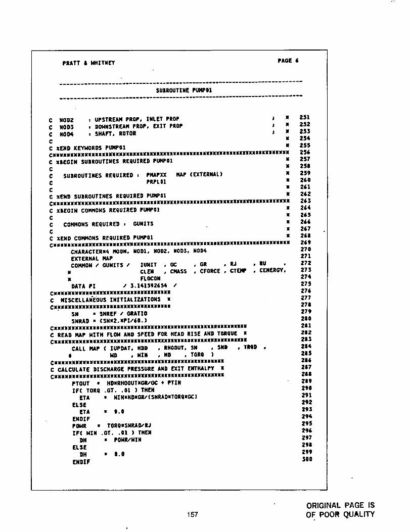
PRATT & HHITN[Y PAGE 6
SUBROUTINE PUMP0|
C NOD2 _ UPSTREAM PROP, INLET PROP ; X
C NODS * DOHNSTREAH PROP, EXIT PROP i XC NOD4 s SHAFT, ROTOR ; X
C xC xEND KEYHORDS PUMPOI xCXUXxxxxxxxuxxxxxuxuxxxxxxxxxxxxxuxxxuuuuxwxuluxxwuxxuxxxxxHxxxnxxxC XBEGXN SUSROUTZNES REQUIRED PUMPO!
CC SUBROUTINES REQUXRED J PMAPXXC PRPLOI
CC XEMD SUBROUTINES REQUIREO PUMPOI
HAP (EXTERNAL)
CIWlIIIIIMIIIIIIIIIliWllIIIWIiiliWIIIilIWIlillMWlIIXIIIWli[IIIWIIIlIlI!
C X|EGZN CONMONS REQUXRED PUMPOI XC u
C CGHHOHS REQUZRED * GUNITS NC X
C XEND COMMONS REQUZRED PUHP0| xCMNNMMMNMMMMKMIMMMNNMKMMNMMMXMNMXMMXMMMIMMMXMXMXMMNMMKIKillnEIIINIMMMNIM
CHARACTERU_ MOON, NODI, NOD2, NOD3, NOD4EXTERHAL HAPCOMHON / GUNXTS / XUNXT , GC , GR , RJ , RU
x CLEN , CHASS , CFQRCE , CTEHP , CEN[RGY,x FLOCON
DATA PI / 3.141592654 /CxuuxxuxxxxuHxxxxxxuxxxxxxxxxwuuxxC MISCELLANEOUS XNITXALIZATIONS X
CN_NMKMNNNNMMKMMMNMMMXMXXMIIXMMMNMM
SN : SNREF S GRATIOSNRAD • (SNX2.XPZ/60.)
CXXXXxwuxxxxxxxuxxxxHxxxwxxxxxxxxxxxxxxxxuxxuaHxxxunC READ MAP HXTH FLOH AND SPEED FOR HEAD RXSE AND TORQUE xCwxxxxxxxxxwxxxxxxxxxxxxxunwxxxxxxxxwxaxxuxxxxmxwxxHxxw
CALL FlAP ( ZUPDAT, HDD , RHOOUT, SN , SND , TRQD ,
$ HD , N|N , HD , TORQ )CNMMNMMMMMMMKKWMMMMMMMIIMMIMMIMNKKWMMWMXMMIMENMMMMM
C CALCULATE DISCHARGE PRESSURE AND EX|T ENTHALPY •CXXXXXMuxWUwxxxxxxxxxxxxxxXXXXXUXXnaXXWXXXXXXXXXX
PTOUT • HDXRHOOUTXGRSOC _ PTXNIF( TORQ .ST..01 ) THEN
ETA = HINxHDxG/V(SNRADXTORQxGC)ELSE
ETA : 0.0ENDZF
POHR • TORQXSNRAD/RJXF( HIN .OT. .Ol ) THEN
DH • POHI_HZNELSE
DH • Q.|
ENDZF
251252
25325_
2552562572S8
259263261
262263
264265266
267268269270
2712?2273274
275276277
278279280
281282283
28428S286
287288289
2q)O291
292293
224
295296
297298
299
30O
157ORIGINAL PAGE IS
OF POOR QUALITY
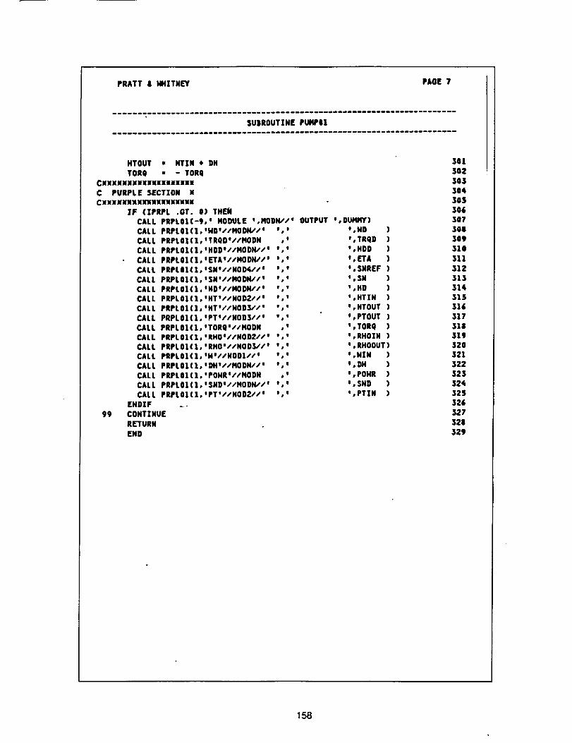
PRATT | HHZTN[Y PAGE 7
SU|ROUT|N[ PUIqP|I
HTOUT • HTZN • OHTORQ m - TORQ
CxXXXXXXxxxxxnxxxxxC PURPLE SECTION •CxxXxxxxxxxxxnnuxe
IF (IPRPL .GT. l) TNEMCALL PRPL0|(-9, ° NODULE °,HODN,'/_ OUTPUT J,DUI41¢Y)CALL PRPLOZ(],°ND°//HODIV/° w,m o,H D )
CALL PRPLO|(|,OTRQDt//HODN ,o O,TRQ D )CALL PRPLOI(I,°HDDO//HODN"S ° e I _,HDD )CALL PRPLO|(I,WETAI//NODK//° o,t *,ETA )
CALL PRPLOI(lo°SN°//NOD(_'/a J,* I,SNREF )CALL PRPLel(1,'SN'//HODIt//e , m o,S N )CALL PRPLOI(I,'ND°/sHODH//* : w :,HD )CALL PRPLOI(I,'HTt//NOD2//w ',' m,HTIN )
CALL PRPLOI(I,°NT://NOD3//* ,,I U,HTOUT )CALL PRPLOICI,°PT*//NODS//' %' *,PTOUT )CALL PRPLOI(X,*TORQa//HODN ,w g,TORQ )
CALL PRPLOI(I,'RHOO/SNODI//* *," I' RHOZN )CALL PRPLOI(I,°RHO'//HODS//° ',' °,RHOOUT)CALL PRPLOI(I,°H°//NODI//* m,, I,NIN )CALL PRPLOI(I,°DH*//HODN//* *,w t,DH )CALL PRPLOI(I,'PONR'//HODN ,w o,poH R )
CALL PRPLOI(I,ISND'I/NODK//l w,o I,SND )CALL PRPLOI(I,*PT'//NOD2//' ',' ',PTIN )
ENDIF ..
99 CONTINUERETURN
END
301
3O2303
30¢30S306307
308309310
311312
31331¢315316
31731831932O321322
323324325
326327328
329
158
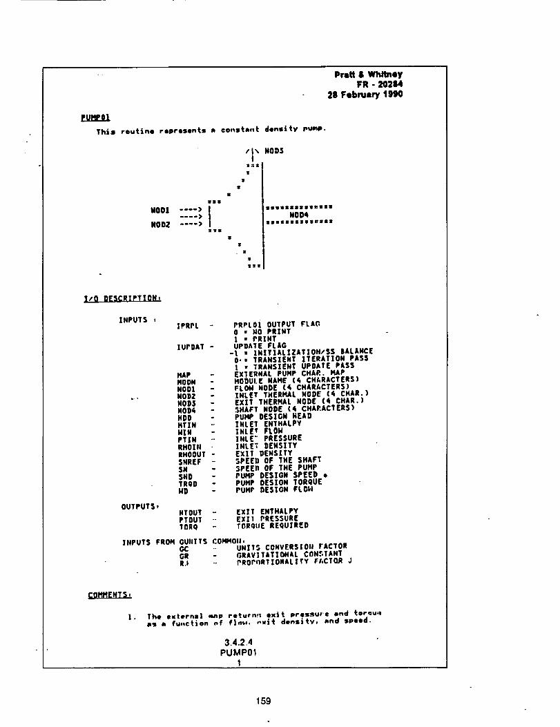
euxine]
Thtm routine represents n ©o_ste.t density puu.
,sl
MODi .... ) !NOD[ .... >_Tt
/I_ NOD3fs
T
I
I¢
Ir
IIIIIIIIIM_III
NO_
Prat/S WhitneyFR - 20214
28 February 1990
X/O DESCRXPTION,
XNPUTS s
OUTPUTSI
INPUTS FROH
fPRPL -o
]UPDAT -
MAPMOON -NODI -NOD2 -NODS -NOD6 -HDD -HTIN --NIH -PTIH "-RHOIN --RHOOUT -SNREF .-SNSNO -TROD -HD
PRPL0i OUTPUT FLAG0 = NO PR|HTI • PRINTUPDATE FLAG
-I : IN]TIALZZAT|OH/SS BALANCE0.* TRANSIENT ]TERATIOH PASS| • TRANSZENT UPDATE PASSEX]ERNAL PUMP CHAR. HAPMODULE NAHE (q CHARACTERS)FLOM NODE (4 CHARACTERS)ZNLET THERMAL NODE (4 CHAR.)EXXT THERMAL NODE (4 CHAR.)SHAFT NODE (6 CHARACTERS)PUMP DESIGN HEADZNLET ENTHALPY]NLE? FLOMINLE" PRESSUREINLET DENSITYEXIT DENSITYSPEED OF THE SHAFTSPEEn OF THE PUMPPUHP DESIGN SPEED •PUMP DES[ON TORQUEPUMP DESIGN FLOH
HTOUT .- EXIT EHTHALPYPTOUT -- EXI1 PRESSURETOR9 -- TORQIIE REQUZRED
GUUTTS COMMOli,GC UNrTS CONVERSION ]ACTOROR flRAVITAT|ONAL CONSTANTR.I PROrORTXONALITY FI, CTCLR J
The external nmm returns; exit pressuee, snd torau,ea5 e fu-c_on nf f|_. ,,_it denslty, ahd speed.
3.4.2.4PUMPOl
1
159
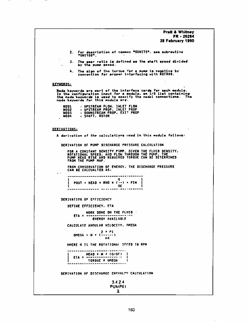
Pratl & Whitney
FR - 20284
28 February 1990
2.
3.
For description of con.on mGUNITS*, see subroutine
"UHIT00 w .
The gear ratio is defLned as the shaft speed dividedby the pump speed.
The sign of the torque for a pump is n.s.tire byconvention for proper interfacing wi+.h ROTR00.
XE_ORDS,
Node keywords are port of the interface cards for eech modu|e.In the oonf|guretton input for a modu|e, an I/O |ist containLngthe node koyword8 ie used to specify the nodal connections. Thenode koywords for this module ere,
NOD1 , UPSTREAH FLOW, INLET FLOHNOD2 , UPSTREAM PROP, INLET PROPNODS z DONNSTREAM PROP, EXIT PROPNOD_ t SHAFT, ROTOR
DERTVATTONSt
A derivation of the calcu|ations .sod Jn this module fol|otas,
DER|VAT|ON OF PUMP DISCHARGE PRESSURE CALCULATION
FOR A CONSTANT DENSITY PUMP. GIVEN THE FLUID DENSITY.ROTATIONAL SPEED, MID FLON TIIROUGN THE PUHP, THEPUMP HEAD RXSE AND REQUIRED TORQUE CAN BE DETERMINEDFROM THE PUMP MAP.
FROM CONSERVATION OF ENERGY. THE DISCHAROE PRESSURECAN |E CALCUALTED AS,
I o tPOUT • HEAD • RHO u (--1 • PIN II GC I
.--......I.ii..i .............-...----..
DERIVATION OF EFFICIENCY
DEFINE EFFICIENCY, ETA
HORK DONE 011 THE FLUIDETA I .......................
ENERGY AVAILABLE
CALCULATE ANGULAR V_LOCITY. MMEGA
2 _ PI
OMEGA = H • ( ...... )_n
HHERE 14 IS THE ROTATIONAl. sPrED IW RPM
I TORQUE u OMEGA I.........._............. ......
DERIVATION Of DISCHARGE ENTItALrV CALCULATIFlH
3.4.2.4
PU_PO!2
160
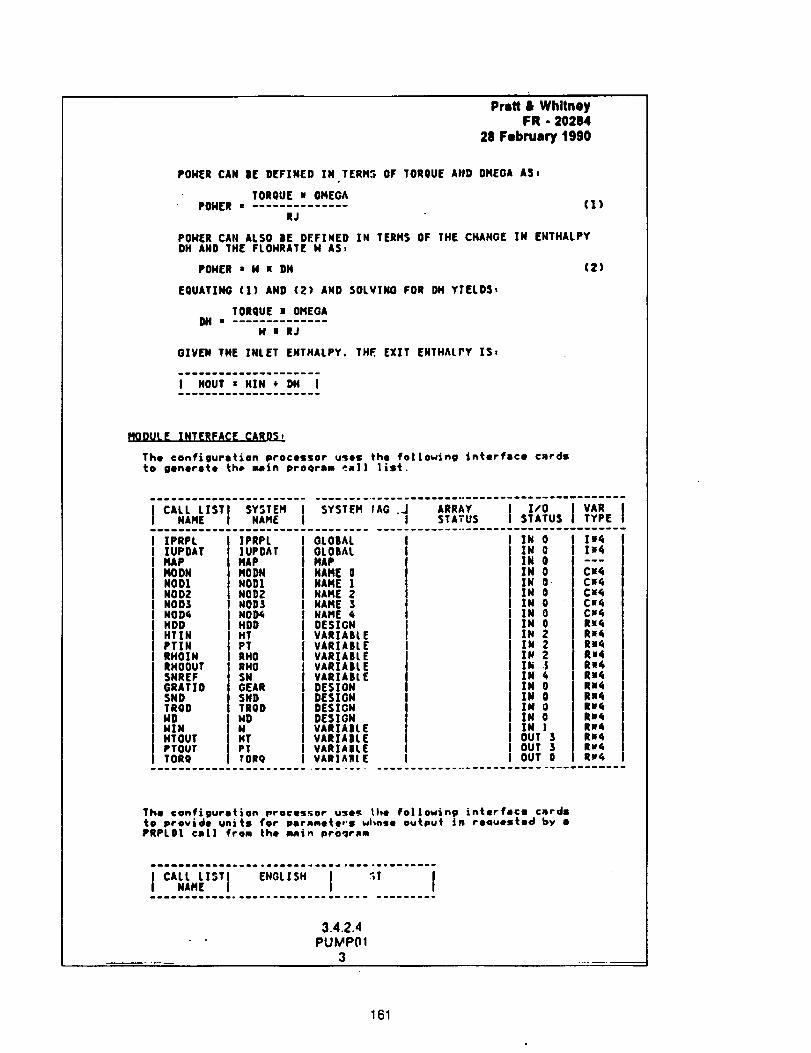
Prstt & WhitneyFR - 20284
28 February 1990
PONER CAN |E DEFINED IN TERMS OF TORQUE AND OMEGA ASt
TORQUE u OMEGAPOHER • ..............
RJ(1)
POHER CAN ALSO |E DEFINED IN TERMS OF THE CHANGE IN EHTHALPYDH AND 1HE FLOHRATE N ASz
POHER • N n DH
EQUATING (1) AND (2) AND SOLVING FOR DH YXELDS,
TORQUE u OMEGA
H| RJ
GIVEN THE |NLET EHTHALPY. THE EXIT ENTHALPY %S,
(Z)
m..w_ww....w. ........
MODULE XNTERFACE CARDS,
The configuration processor uses the fo|]owjng interface c_rdsto generete th@ main proqram _al| list.
][PRPLIUPDATMAPMODNNOD|NOD2NODSNOD4HDDHT|NPTIHRHOINRHOOUTSNREFGRAT]OSNOTRODNDNXNHT OUTPTOUTTORe
IPRPL|UPOATMAPMOONNOD1NOD2NODSNOD4NODHTPTRHORHOSNOEARSNOTRODNDNHTPTTORQ
GLOBAL I I IN 0OLO|AL I I ZX 0
.,,!i,.oNAME 0 l N 0NAME ! XN O-NAME 2 IN 0NAME $ I IN 0NAME 4 j I IN 0OESXGN I I XN 0VARXABL E I I %N 2VARIABLE I I XN 2
VARXAILE I ! Z_ 2VARIA|LE i Xh .5VARXA|LE ZN 4DESIGN I IN 0
DESIGN I j ZN 0DESIGN I XN 0DESXGH I XN 0
VARTAIILE I IN ]VARZA|L( I OUT $VARIAIL( I I OUT 3VARIAB{ E I I OUT 0
|hi41_4
_ww
C_4C_4CwC_CII¢iC_4RnC_Rn4Ru6R.4Ru4Re4RU4Rs'lRe¢RW,
Re4Rw4Rut,
The configuration proces._or uses the fol|owin9 interface cmrdstO provide units for pernmete,'s whnse output jn ro4uested by •PflPL01 taX] from the m_|. proqr_m
mwm_wmm.m_m_o.m_ oeemmme.emw_ .......w.g....
I I I
3.4.2.4
PU_P(11
3
161
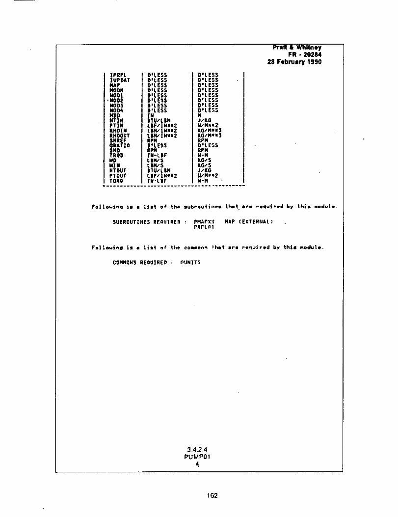
ZPRPLZUPDATMAPHODNNOD!
•NOD2NODSNOD_HDDHTIHPTZNRHOZNRHOOUTSNREFORATIO5NDTRQDNDNINHTOUTPTOUTTORQ
DILESSDWLES5DgLESSDILESSD'LESSD'LESSDILESSDILESSINJTU,'L IIMLIIF/INUl2L|I4/IHuu2L |lq,' 1Nu"2RPHBILESSRPHIN-LIIFLI_SLIH/'S|TU/L IIHLIIF/]r HI u2|N-LBF
DILESSDeLESSD'LESSD°LESSD'LESSD°LESSDWLESSDOLE.';SHJ/KOH/PIN_ZKO/'Hxu3KO,'N'fx3RPND°LESSRPIqH-NKGs SKG,'SJ/KG/I/MP_2H-M
Pratt & WhitneyFR - 20284
28 February 1990
Fol|owing is • List of th_ subrouti--s tilt ore required by this module.
SUBROUTZNES REQIJTRED : PHAPXX HAP (EXTERtJAL)PRrL01
Following is • list of the common_ Fhet ore required by this module.
COt'lHON$ REQUIRED : _UNJT3
3.4.2.4
PUMP01
4
162

Appendix CInterfaced NASA Control Model
Presented is the listing of the NASA MSFC FORTRAN Control Model with the ROCETS interface
incorporated in the comment cards.
163
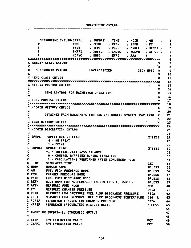
SUBROUTINECNTLO0
SUBROUTINE CNTLOO(IPRPL , IUPDAT , TIME , HODN , QN ,
t PCN , PFDN , REFN , QFFH , PC • ,
# PFD1 , TFPZ , PCREF , HRREF , DXOPZ ,
$ DXFPI o XMFVC , XMOVC , XCCVC , XFPVC o
# XOPVC , EOPI , EFPI , AAA )
CX_XXXX_X_IXX)k_XEX_XXXXXXXXi_XXXX_KXXX_IX_XXXXXXXXXXXXXX_X_X_XXl_IXXX
C XBEGZN CLASS CNTLO0 X
C "X
C SUBPRDGRAM CMTLO0 UNCLASSIFIED SID: E950 XC x
C XEND CLASS CNTLO0 . x
CxX_xXX]_]_`J(xx_][]FJ(XxXx_xXxXXx_XXXx_X_xxx_X_xxxxx_xXxXx_XxxXx_x%_J(_
C XBEGIN PURPOSE CNTLO0 --C
C SSI_E CONTROL FOR MAIHSTAGE OPERATION x
CC _END PURPOSE CMTLO0
CXXXx_x_F, exxxx_xxxxx_x_xxxxxx_xx_x_xxxxxxx_xx_xxxx_x__xxx_
C XBEGIN HISTORY CNTLO0 -. x
C _
C OBTAZNE_ FROM NASAIMSFC FOR TESTING ROCETS SYSTEM HAY 1990 xCC XEND HISTORY CNTL00 x
C XBEGIN DESCRIPTION CNTLO0C
C IPRPL
C
C
C ZUPDAT
C
C
C
C TIME
C HODN
C qN
C PCN
C PFDNC REFN
C gFFM
C PC
C PFDL
C TFPI
C PCREF
C MRREF
C
PRPLOI OUTPUT FLAG| = NO PRINT
1 • PRINT
UPDATE FLAG
-1 • INITIALIZATION/SS BALANCE
0 z CONTROL BYPASSED DURING ITERATION
1 = CALCULATIONS PERFORMED AFTER CONVERGED POINTSINULATE_ TIME
MODOLENAME
FUEL FLON+FEEDBACK NODE
CHAMBER PRESSURE NODE
FUEL PU_D DISCHARGE NODE
NODE NAME FOR eREFERENCE _ INPUTS <PCREF, MRREF)MEASURED FUEL FLOH
MEASURED CHAMBER PRESSURE
MEASURE_ LON PRESSURE FUEL PUMP DISCHARGE PRESSURE
MEASURED LOH PRESSURE FUEL PUMP DISCHARGE TEHPERATUREREFERENCE (REQUESTED) CHAMBER PRESSURE
REFERENCE (REQUESTED) MIXTURE RATIO
C INPUT ON IUPDAT:-I, OTHERHZSE OUTPUT
C
C DXOPZ OPV INTEGRATOR VALUE
C DXFPI FPV INTEGRATOR VALUE
D'LEss
D_LESS
SEC
D'LESSD_LESS
D'LESS
D_LESS
DeLESS
oPIq• PSTA
PSIA
DEG. R
• PSIA
D-LESS
PCT
PCT
1
23
5
6
78
910
11
12
13
14
15
1-6
17
• 1819
20
2122
23
2¢
2526
27
2829
30
3132
33
3_
35
36
37
38
39
qO
¢1
q2
43
45
_6
_7
48
49
50
164
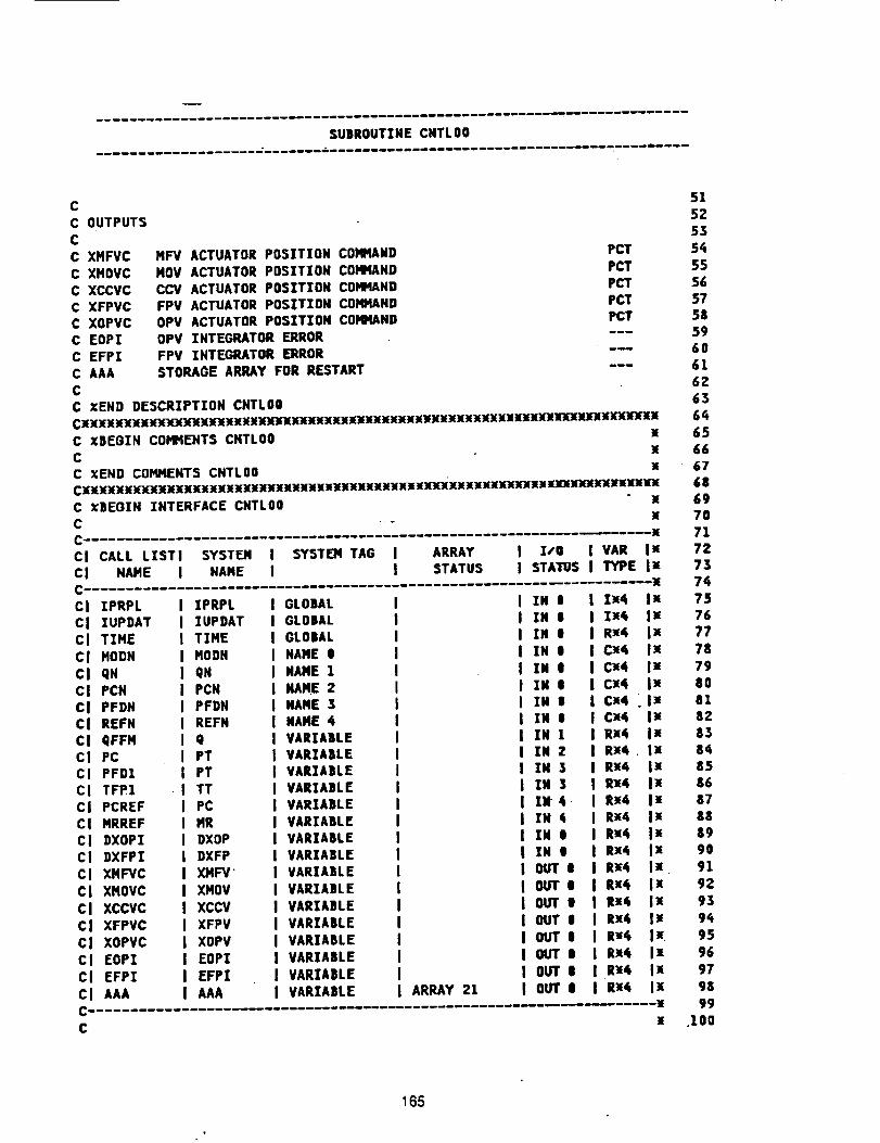
SUBROUTINECNTLO0
CC OUTPUTSCC XMFVCC XHOVCC XCCVCC XFPVCC XOPVCC EOPIC EFPI
C AAA
C
HFV ACTUATOR POSITION COMHAND
NOV ACTUATOR POSITION COMMANDCCV ACTUATOR POSITION COMMAND
FPV ACTUATOR POSITION COMMANDOPV ACTUATOR POSITION COMMAND
OPV INTEGRATOR ERRORFPV INTEGRATOR ERROR
STORAGE ARRAY FOR RESTART
PCTPCT
PCT
PC1"_T
°X
X
,X
I ARRAY I I/O I VAR IxI STATUS I STATUS I TYPE IN
C XBEGIN INTERFACE CNTLO0C
CI CALL LISTI SYSTEM I SYST_ TAG
CI NAME I NAME I
GLOBAL
GLOBAL
GLOBALNAME O
NAME 1
NAME 2NAME 3
NAME 4VARIABLE
VARIABLEVARIABLE
VARIABLEVARIABLE
VARIABLE
VARIABLEVARIABLE
VARIAmLE
VARIABLE
VARIABLEVARIABLE
VARIABLE
VARIABLE
VARIABLE
VARIABLE ARRAY 21
I IN I I Ix4 IxI IN t I Ix_ Ix
I IN I I Rx4 Ix
I IN I | Cx4 I_
I IN t I Cx4 I_I IN t I Cx¢ Ix
I IN I I Ca4 _lxi IN i I Cx_ Ix
I IN 1 I Rx4 IxI IN 2 I Rx4. Ix
I IN 3 I RX4 ix
I IN 3 I Rx4 Ix] IN 4 _ I R_4 I_
I IN 4 I Rx4 IxI IN i I R_4 IxI IN e I Rx¢ IxI OUT e I Rx4 IxI OUTe I Rx4 IxI OUT e I i_¢ IxI OUT e I Rx4 IxI OUT e I R_4 Ix.I OUT O i Rx6 I_I OUT e I R_4 I.I OUT e I Rx4 Ix
:II
Cl IPRPL I IPRPLCl IUPDAT I IUPDATCl TIME I TIHE
CI MODN I HODNCl qX I QN
Ci PCH I PCN
CI PFDN I PFDNCI REFN I REFH
CI qFFM I qcI PC I PT
CI PFD1 I PTCI TFP1 -I TT
CI PCREF I PCCI MRREF I MR
Cl BXOP! I DXOPCI DXFPI I DXFP
Cl XMFVC I XMFV"Cl XMOVC I ×MOVCI XCCVC I XCCVcl XFPVC I XFPVCI XOPVC I XOPVCI EOPZ I EOPI
CI EFPI I EFPICI AAA I AAA
C
51
5:'
5.3
5455
56
5758
5960
6162
65
65
6667
6869
7071
7273
7475
7677
78
79
aOal
82
838485
8687
88
8,990
91
92
9,3
9495
96
97
9&
99
.100
165
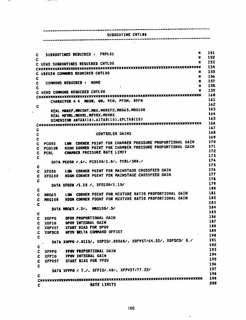
SUEROUTINECNTLO0
C SUBROUTINES REQUIRED , PRPL01 x
C
C XEND SUSROUTXNE3 REQUIRED CNTLO0 xC_XX_XXnXXX_E_XX_HX__X_XXX_XX_XX_XXXXXXXXXXXXXXX_XXXMXXX_
C XBEGINCOI4NINIS REQUIRED CNTLO0 x
C xC COMHOMS REQUIRED , NONE X
C xC XEND COHHOH$ RE_IIRED CNTLO0 xCxXXXXMXXnXMnXXXXXXXXXX_XXX_X_XXXXXX1(XXXXXXXXXXXXXXXXXXxixxXXXXXXX_XX
CHARACTE_ x 4 MOD#, QN, PCN, PFDH, REFNC
REAL MIUtJEF,IHCONT,HRG,HRREFX,HRG6$,HRGIO0
REAL HFYRLoltOVRL,HFVRX, HOVRX
DIMENSION AITA|(IO),A1TAB(IO),EPLTAB(IO)CXMXXXXXX_MXXHXnXXXXXXXXXXXXXXXXXXXXXXXXXX_XXn__XX_X_XXC
C
CCC
CC
C
CC
C
C
C
CC
C
C
CC
CC
PCGSO
PCOIO0PCRL
COHTROLER GAINS
LOM CORNER POINT FOR CHAHBER PRESSURE PROPORTIONAL GAIN
HIGH CORNEA POINT FOR CHAHBER PRESSURE PROPORTIONAL GAIN_l_t PRESSURE RATE LIHIT
DATA PCGSO /.6/o PCGIO0/I.O/, PCRL/300./
XFG50 LOM CORNER POINT FOR MAZNSTAGE CROSSFEED GAIN
XFGIO0 HIGH CORNER POINT FOR HAINSTAGE CROSSFEED GAIN
DATA XFG$O/1.1S /, XFG100/1.15/
MRG65
MRGIO0
LOM CORNER POINT FOR MIXTURE RATIO PROPORTIONAL GAIN
HIGH CORNER POONT FOR MIXTURE RATIO PROPORTIONAL GAIN
DATA i'IR_5 1.2,% HRGIO0/.5/
XOPPG OPOV PROPORTIONAL GAIN
XOPIO OPOV ZNTEORAL GAINXOPVST START |IA3 FOR OPOV
XOPDCO 01'01( KLTA COHHAND OFFSET
DATA XOPPGI.0113/, XOPIG/.O0068/, XOPVST/6_.52/, XOPDCO/ 0./C
C XFPPG FPOV PROPORTIONAL GAIN
C XFPZG FPOV INTEGRAL GAINC XFPVST START DIAS FOR FPOV
C
DATA XFIPPO / 7.1, XFPZG,,._O/, XFPVST/77.22/
C
C RATE LIHZTS
151152
153
15_
155
156157158
159160
161
162163
164
165166167
168
169170
171172173
17,175
176177
178179
180
181
182
183184
155186
187188
189
190191
192
193
19_
195
196
197
198199
200
166
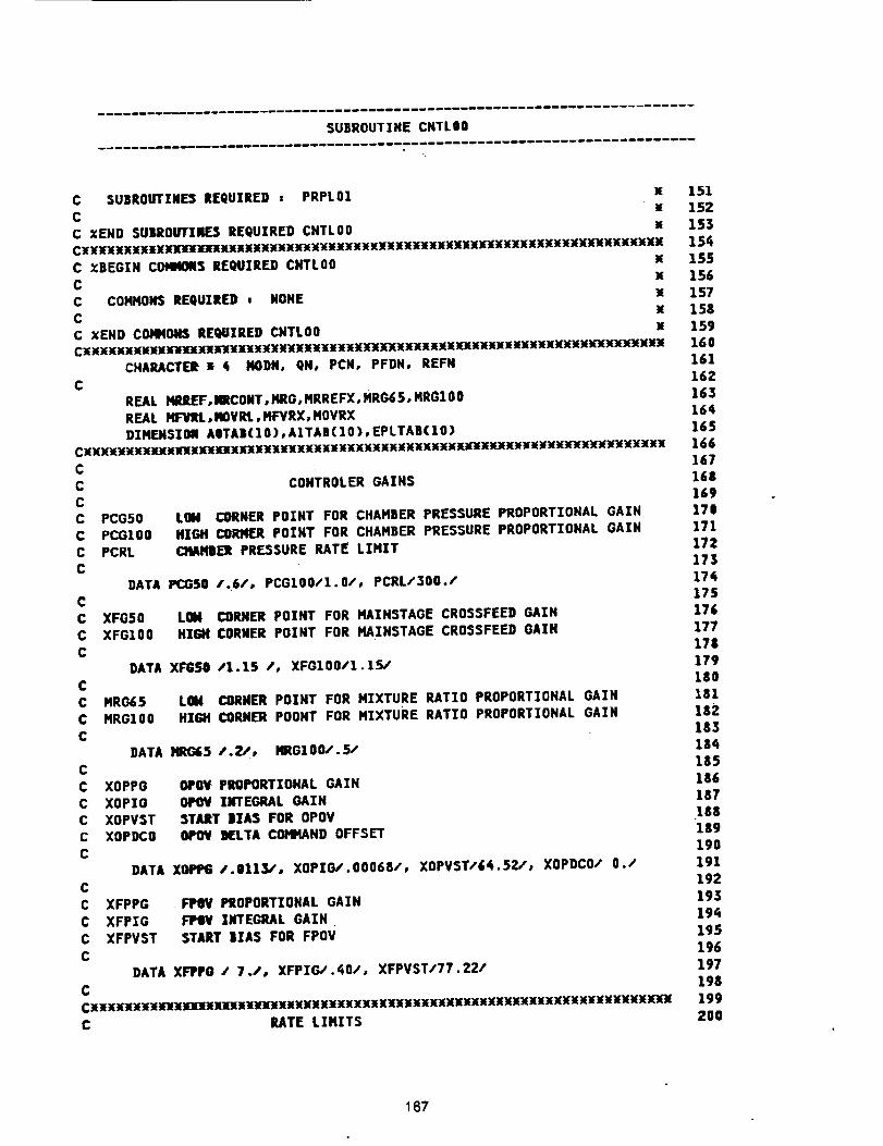
SUBROUTINE CNTLO8
C SUBROUTINE_ REQUIRED = PRPL01 XC
C XEMD SU)ROUTINES REQUIRED CNTLO0 xC_XXx;xxnxmom]mxxxln_xn_x_x_Hxx_nx_Hxxxxxxxxxxxxxxx_xxlxxlm(
C XBEGIN COMMONS REQUIRED CNTLO0 x
C x
C COMMONS REQUIRED , NONE MC x
C XEND COHKO#S REQUIRED CNTLO0 xCXXXXXXX_NX_XamXXiX_X_X_Xl_XXiXXXXXII_XXMM_MIXXX_X_X_r_X_X_
CHARACTER x _ NODN, QN, PCN, PFDN, REFNC
REAL NR2EF,NCONT,MRG,MRREFX,HRG6$,MRGIO0
REAL HFVRL,MOVRI.,MFVRX,HOVRX
DIMENSION AOTAB(IO),A1TAB(IO)oEPLTAB(IO)C_KKK_XXXX:EN]k'XXXXXXXXX_XXXKXXXX_XXKX_K_KK_K_K___K_O(_X_XXKC
C CONTROLER GAINSC
C PCG50 LOM CORNER POINT FOR CHAMBER PRESSURE PROPORTIONAL GAINC PCGZO0 HIGH CORJ_ER POINT FOR CHAMBER PRESSURE PROPORTIONAL GAIN
C PCRL OtAflBER PRESSURE RATE LIMITC
DATA PCGSO /.6/, PCGIO0/I.0/, PCRL/300./C
C XFGSO LOM CORNER POINT FOR MAINSTAGE CROSSFEED GAINC XFGIO0 NIGH CORNER POINT FOR MAZNSTAGE CROSSFEED GAIN
C
DATA XFGSO /1.1S /, XFGlO0/l.15/CC MRO65
C MROlO0
C
C
CC
CC
C
LOM CORNER POINT FOR MIXTURE RATIO PROPORTIONAL GAINHIGtJ CORNER POOHT FOR MIXTURE RATIO PROPORTIONAL GAIN
DATA I'IRG&5 _.2,", MRGIO0/.5/
XOPPGXOPIG
XOPVST
XOPDCO
OPOV PROPORTIONAL GAINOPOV INTEGRAL GAIN
START BIAS FOR OPOV
OtO_ I_rI.TA COMMAND OFFSET
DATA XOPP6/.8113/, XOPIC_'.O0068/, XOPVST/_(.J2a', XOPDCO/ 0./C
C XFPPG
C XFPEG
C XFPVST
C
1_ PROPORTIONAL GAIN
FPOV ]MTEGRAL GAINSTART |IAS FOR FPoV
DATA XFPPO / 7./, XFPIG/.¢O/, XFPVST/77.22/
C
C RATE LIMITS
151
152153
154
155154
157
158159
160
161162
163164
165166
167
16|169ITO
171172
173
17q175
17_177
178
179180
1811S2
185
185
187
lS8
lsg190
191
192
193194
195
196
197198
199
200
167
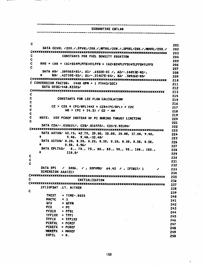
$U)ROUTZNECNTL0e
CDATACCVRL/200./,FPVRLI200./,NFVRL/200./,OPVRL/200./,HOVRL/200./
CXXXxtxx_xxxxxxxxxxx_xxxxxxxx_xxxxx_i_x_Je_XxMxxnxxxxxx'xxxx*xx_xxxxxxx
CONSTANTS FOR FUEL DENSZTY EQUATZONCC
CC
RHO = (AO + CAI*|lXPLPFD)XTLPF9 * (A2÷B2xPLPF])xTLPFgXTLPFD
DATA AO/ .38956E+01/, A1/ .6522E-01 /, A2/-.140|_AE-O2,%BO/ .42739E-02/, |1/-.2i467E-03/, 02/ .309Z6E-05/
CX_M_I_XXXXXXXXMXXXXXUXXXXXXXX'JeXXXXXXXXXNXXX_XXMXXXXKXXXXXXXXXX
C CONVERSZOH FACTOR, (4_8 GPH " 1 FTxx_'SEC)DATA GTOC,'44&.83303/
CX_XXX_X_X_X_XXXXXXXXXXXXXXXXXXXnXXXX_Ik'_XX'k'xrxxk'X_XXXXH_llXXX
NOTEs
COHSTANT$ FOR LOX FLOHCALCULATIOH
CZ = C2A _ (PCIRPL)_2 + C280(PC,"RPL) + C2CHO = (PC ÷ 1_.5) /(:2 - i4t
USE PCREF zHsTF.AD OF PC DURZNG THRUST LIHIT]NG
DATA C2A/-.030621/, C20/.016555_', C2C/2.92104/
DATA AOTAB/ _2.75e _2.75, $9.00° $5.00° $5.00° 17.00, 9._0,
t 9._0, 9._0,-32._8/
DATA AITA8/ 0.20, 0.20, 0.25, 0.30, 0.30, 0.50, |.5_, 0.58,t 0.58, 0.96/
DATA EPLTAS/ 0.o 70., 75., 80., 85., 90., 95.o 100., 105.,t 110.0/
C
CC
DATA RPL / 3006. / , XOPVHX/ 64._3 / , ZFZRST/ 1 /
D|HENSZON AAA(21)Cx_Xxx_xxxxxx_xxxxx_x_xxxx_xxxxxn_x_x_xxxx_xxxxxx_xx_xxxxx_xxxxx
C INITIALIZATION
IFCIUPDAT .LT. O)THENC
TN[XT = TIME-.OOZ5
MNCYC = $
QFX = qFFNPCX = PC
PFDIX = PFD1
TFPIXX = TFP1
TFPIX = TFPIXX
PCRFXL • PCREF
PCREFX • PCREF
MRREFX = MRREF
EOPIL = 0.
201202
203
20_2O5
206207
Z08
209210
211212
21321_
215
216Z17210
21927.0
221222
223
22_iZ25
226Z27
228229
230231
232Z33
235236
237
238239
2_0
2_;1
2_;Z
2_3
2_i42_5
2q6
2q7
2_8
2_9250
168
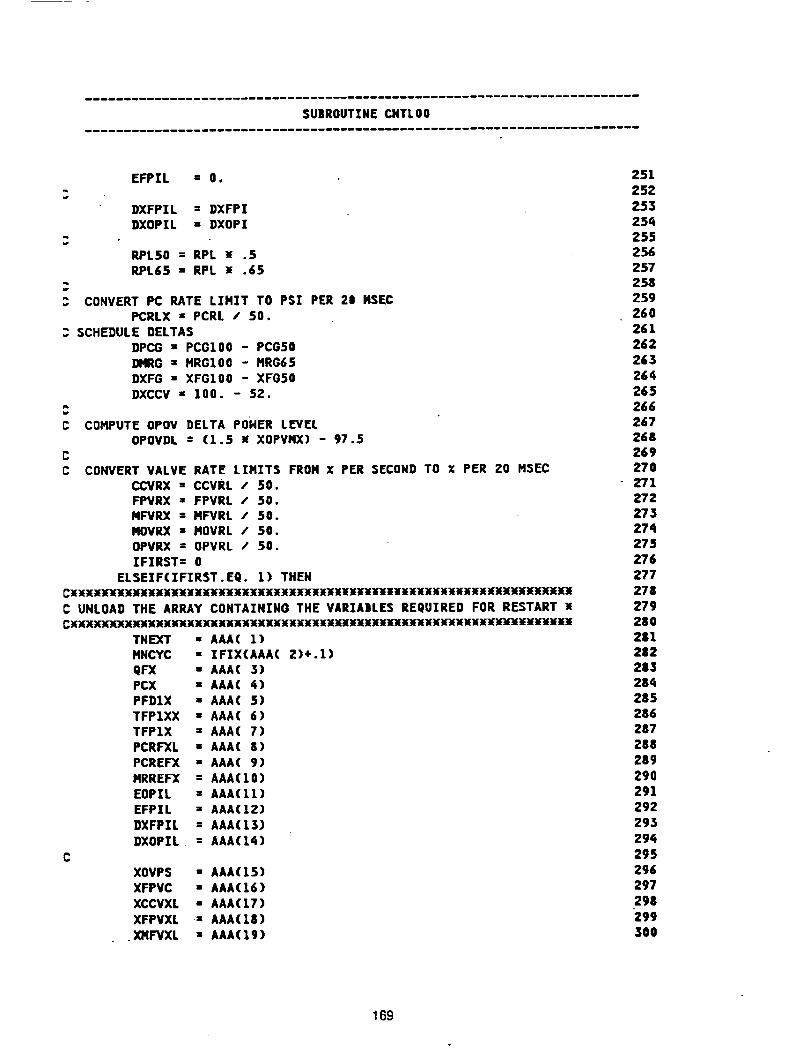
SU|ROUTIHECHTLO0
EFPIL " O.
DXFPIL : DXFPI
DXOPIL : DXOPI
RPL50 = RPL ; .5
RPL6S = RPL _ .65
CONVERT PC RATE LIHIT TO PSI PER 20 MSECPCRLX = PCRL t 50.
SCHEDULE DELTAS
DPCG = PCGIO0 - PCGSO
DIqRG = HRGIO0 - HRG65DXFG = XFGIO0 - XFGSO
DXCCV • 100. - 52.
COMPUTE OPOV DELTA POHER LEVELOPOVDL : (1.5 x XOPVMX) - 97.5
CONVERT VALVE RATE LIMITS FROM X PER SECOND TO X PER 20 MSECCCVRX = CCVRL / 50.
FPVRX = FPVRL / 50.MFVRX = MFVRL / 50.
MOVRX • MOVRL / 50.
OPVRX = OPVRL / 50.IFIRST= 0
ELSEIF(IFIRST.EQ. 1) THEN
UHLOAD THE ARRAY CONTAINING THE VARIABLES REQUIRED FOR RESTART M
_KKKKKKKKKKKKKKKKKXKKXXKXXXXNXXKX_KXNIXIKXiiiXX____
THEXT • AAA( 1)
HNCYC = IFIX(AAA(2)÷.1)
QFX • AAA( 3)PCX u AAA( 4)PFDIX • AAA( 5)
TFP1XX • AAA( 6)
TFP1X • AAA( 7)PCRFXL u AAA( 8)
PCREFX • AAA( 9)
MRREFX = AAA(IO)
EOPIL = AAA(11)EFPIL • AAA(12)
DXFPIL = AAA(I$)
DXOPIL. = AAA(14)
C
XOVPS • AAA(15)XFPVC " AAA(16)
XCCVXL • AAA(17)
XFPVXL = AAA(18)
XMFVXL • AAA(19)
251
252
253254
255256
257Z58
259260
261
2_2263
2_4
265266
267268
26927O
Z71272
273274275
276
277
278:'79
280281
282283
28_i
285286
287288
289
290
291292
293
294
295
296297
298
300
169
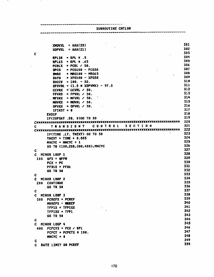
SUBROUTINE CNTLO0
C
XMOVXL : AAAC20)XOPVXL = AAAC21)
301
302303
RPL50 : RPL u .5 304
RPL65 ,, RPL x .65 305PCRLX • PCRL / 50. 306
IDIPC8 w PCGIO0 - PCGSO 307BMRO = IqR0100 - MR065 308
DXFG - XFOlO0 - XFG50 309DXCCV s 100. - 52. 310
OPOVM. = (1.5 x XOPVHX) - 97.5 311CCVRX ='CCVRL / 50. 312
FPVRX = FPVRL / 50. 313MF'VlU( = MFVRL / 50. 314
MOVRX " iqOVRL / 50. 315
OPVRX = OIPVRL I 50. 316
IFIRST = 0 317ENDIF 318
ZF(IUPDAT .Eg. O)GO TO 50 319CXXX_xxxxxxxxxxxnlux_xxxx_x_xx_xxxxx_xxXXxx_xxxxxxx_xxxxxxxx 320C T R A N S I E N T C O N T R O L S E C T T 0 M 321C_X_X_X_UUXXXNUUXX_XXXXXXXNXXX_M_XX__X_xXXXX_XXXXXXX_XXXxxxX 322
IF(TIME .LT. TNEXT) GO TO 50 323TNEXT • TIME + 0.005 524,
MHCYC " MI_'¥C + 1 325
O0 TO (IOO,200,300,400),MNCYC 326C 327
C MINOR LOOP 1 328
100 QFX • QFFIq 329
PCX = PC 330PFDIX = PFD1 331
GO TO 50 332C 333
C MINOR LOOP 2 33di200 CONTINUE 335
.GO TO 50 336C 337
C MINOR LOOP 3 338
300 PCREF'X = PCItEF 339
MRREFX = IgtJtEF 340TFPIX = TFPlXX 341
TFPIXX = TFIP1 342
GO TO 50 343
C 344
C MINOR LOOP _ 345
400 PCPCTX = PC][ / RPL 346
PCPCT " PCPCTX ]( 100. 347MNCYC : O 348
C 349
C RATE LIMIT OK P(_EF 350
170
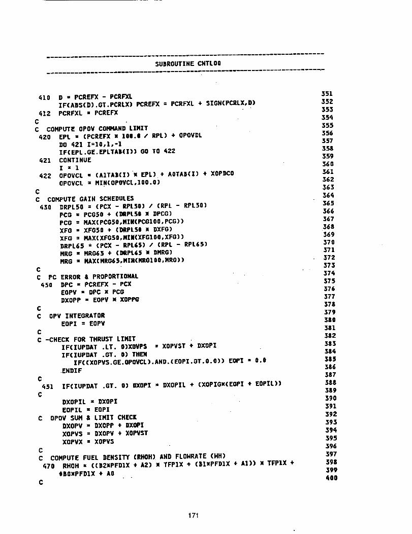
SU_ROUTINECHTLO0
410 D " PCREFX - PCRFXL
ZFCABSCD).GT.PCRLX) PCREFX : PCRFXL + SZGNCPCRLX,D)
412 PCRFXL " PCREFX
CC COHPUTE OPOV COHHAND LIMIT
420 EPI. • (PCREFX ! 10|.1 / RPL) ÷ OPOVDL
DO _Z1 Z=10,1,-1ZF(EPL.GE.EPLTA|(I)) GO TO 422
421 CONTINUEI - 1
422 OPOVCL = (AITA|(I)_ [PL) + AOTAB(Z) + XOPDCO
OPOVCL " HIH(OPOVCL,1QO.O)C
C COHPUTE GAIN SCHEDULES
430 DRPLSO = (PCX - RPL50) / (RPL - RPL50)PCG " PCGSO ÷ (DRPL$O ! DPCG)
PCG = HAX(PCGSO,.NZM(PCGIOO,PCG))
XFO " XFG$O + (DRPL$8 ]_ DXFG)XFG = I*,AX(XFG$O,NZM(XFGIOO,XFG))DRPL6S * (PCX - RPL£5) / (RPL - RPL6S)
HRG • HRG65 ÷ (DRPL6$ ]e DHRG)HRG = HAXCHRG6S,HZN(HRGIOO,HRO))
CC PC ERROR & PROPORTIONAL
450 DPC " PCREFX - PCXEOPV = DPC X PCG
DXOPP = EOPV M XOPPGC
C OPV ZHTEGRATOR
EOPI = EOPVC
C -CHECK FOR THRUST LZI_T
IF(ZUPDAT .LT. O)XOVPS = XOPVST ÷ DXOPZIF(IUPDAT .GT. O) THEN
IF((XOPVS.GE.OPOVCL).AND.(EOPI.GT.O.O)) EOPI = 0.0
.ENDIF
C451
C
IF(IUPDAT .GT. O) DXOPI = DXOPIL + (XOPIGx(EOPI • EOPIL))
DXOPIL = DXOPI
EOPIL = EOPIC OPOV SUH & LIHIT CHECI[
DXOPV • DXOPP ÷ DXOPI
XOPVS : DXOPV + XOPVST
XOPVX = XOPV$
C
C COHPUTE FUEL DENSZTY (RHOH) AND FLOHRATE (NH)470 RHOH = ((B21PFDIX + A2) x TFPIX + (BIIPFDIX ÷ A1)) x TFPIX ÷
SBOMPFDIX ÷ AO
C
351
35Z
353
354355
356357358
35g
360361
362
363364
365366
367
368369
370371372
373
37_375
376377
378379
380
381382
38338¢
385386
387
388389
39O
391
392393
394
395
396
397398
399
400
171
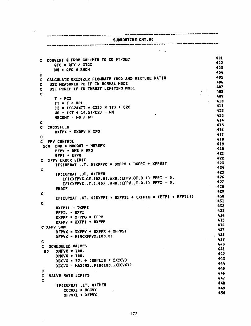
SUBROUTINECNTLO0
CCC
C CONVERTq FROMGAL/NZHTOCUFT/SECgFC= QFX / GTOC
HH ; QFC x RHOH
CC CALCULATE OXIDIZER FLONRATE (NO) AND MIXTURE RATIO
USE MEASURED PC IF IN NORMAL NODEUSE PCREF IF IN THRUST LIMITING MODE
T = PCX
TT = T / RPLC2 = ((C2A_TT + C2B) N TT) ÷ C2C
NO = ((T ÷ 14.5)/C2) - HH
MRCONT = NO / NHC
C CROSSFEEDDXFPX " DXOPV x XFG
C
C FPV CONTROL500 DHR " NRCONT - MRREFX
EFPV " I_IR x MRGEFPI = EFPV
C XFPV ERROR LZNZTZF(IUPDAT .LT. O)XFPVC " DXFPX + DXFPZ + XFPVST
C
C
C
ZF(1UPDAT .GT. O)THEN
ZF((XFPVC.GE.IOZ.O).AHD.(EFPV.GT.O.)) EFPI = O.
ZF((XFPVCoLT.8.00) .AND.(EFPV.LT.O.)) EFP] = O.EHDZF
IF(IUPDAT .GT. O]DXFPI = DXFPIL ÷ (XFPIG _ (EFPI + EFPZL))
DXFPIL : DXFP!EFPIL : EFPZ
DXFPP : XFPPG _ EFPVDXFPV : DXFP! ÷ DXFPP
C XFPV SUNXFPVX = DXFPV ÷ DXFPX + XFPVST
XFPVX = MIH(XFPVXolO0.O)C
C SCHEDULED VALVES
80 XMFVX = 100.
XHOVX • 100.XCCVX = 52. + (DRPLSO x DXCCV)
XCCVX • HAX(SZ.,MZN(IOO.,XCCVX))
VALVE RATE LIMITS
ZF(ZUPDAT .LT. O)THEN
XCCVXL = XCCVX
XFPVXL : XFPVX
401
402
403
404405
406 •407
408409
410411
412
413
415
416417
418419
420421
42Z423424
425426
427
428
'i29'630
431
45Z433
434435
436
437438
_39¢_O
441
44Z
443
444445
446
_7
449
450
172
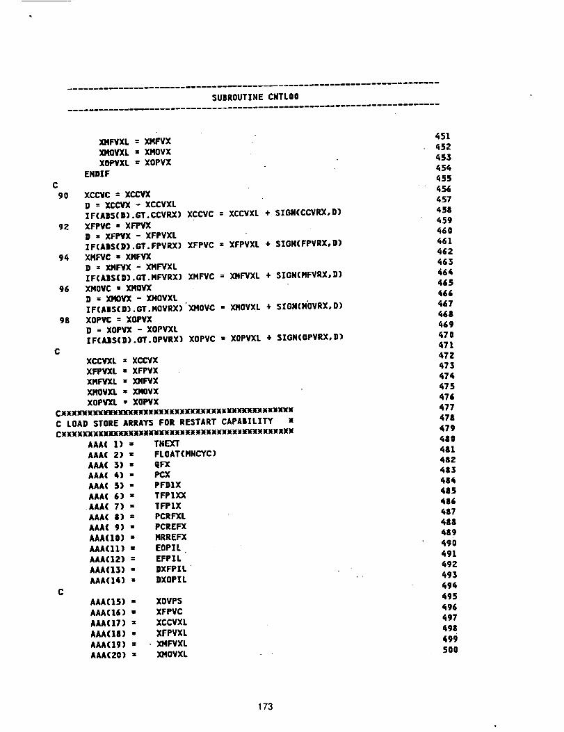
SUBROUTZNE CNTLO0
C
90
C
XHFVXL = XI,IFVXX)IOVXL = XHOVX
XOPVXL _ XOPVXEHDXF
XCCVC = XCCVXD = XCCVX - XCCVXL
IF(A|S(D).GT.CCVRX) XCCVC = XCCVXL + STGN(CCVRX, D)g2 XFPVC " XRPVX
D : XFPVX - XFPVXL%F(ABS(D).GT.FPVRX)
94 XMI:I/C = XHFVXD = XHF"YX - XMFVXL
ZFCA|S(D) •GT. MFVRX)96 XMO¥C " XHOVX
D = XMOV'X - XHOVXLZF(AIS(D).GT.HOVRX)
98 XOPVC = XOPVXD = XOPVX - XOPVXLZFCAJIS(D).GT.OPVRX)
XFPVC = XFPVXL * SZGN(FPVRX, 9)
XHFVC = XHFVXL ÷ SIGN(HFVRX,D)
XHOVC - x]qOVXL + SZON(NOVRX, D)
XOPVC • XOPVXL ÷ SZGNCOPVRX,D)
XCC_L = XCCVXXFPWXL - XFPVX_L = 3041F'VXXMOVXIL = ]OIOVX
XOPVXL " XOPVXCI_X'_EX_X]fJ[_W)fM_IINXXXXXXXXX)(XXKNXX](:E_XXXNXXNC LOAD STORE ARRAY5 FOR RESTART CAPA|ZLZTY xCN_XXXXXXXXXX]O(XXXXNXX)_XXIIN_XX_lX_qI(_YNXXXXN
AAA(]) = TNF._r
C
AAA(2) : FLOAT(MNCYC)
AAA( 3) " QFXAAA( 4) " PCXAAA( 5) " PFDIXAAA(6) = TFPIXX
AAA( 7) " TFPIXAAA(8) : PCRFXL
AAA(9) = PCREFXAAA(IO) : NRREFX
AAA(11) • EOPZLAAA(12) : EFPZLAAA(13) - DXFPIL
AAA(14) : DXOPIL
AAA(]5) " XOVPS
AAA(16) : XFPVCAAA(17) - XCCVXL
AAA(18) • XFPVXLAAA(19) _ - XNFVXL
AAA(ZO) " XHOVXL
451452_53454
q55
_56457';58
r_59_6o
462_63464
465_66
467468co69
471
47=473_74475476
477478479
4110481482483
484485486487
488489
490491492
493494
495
496497
498499
500
173
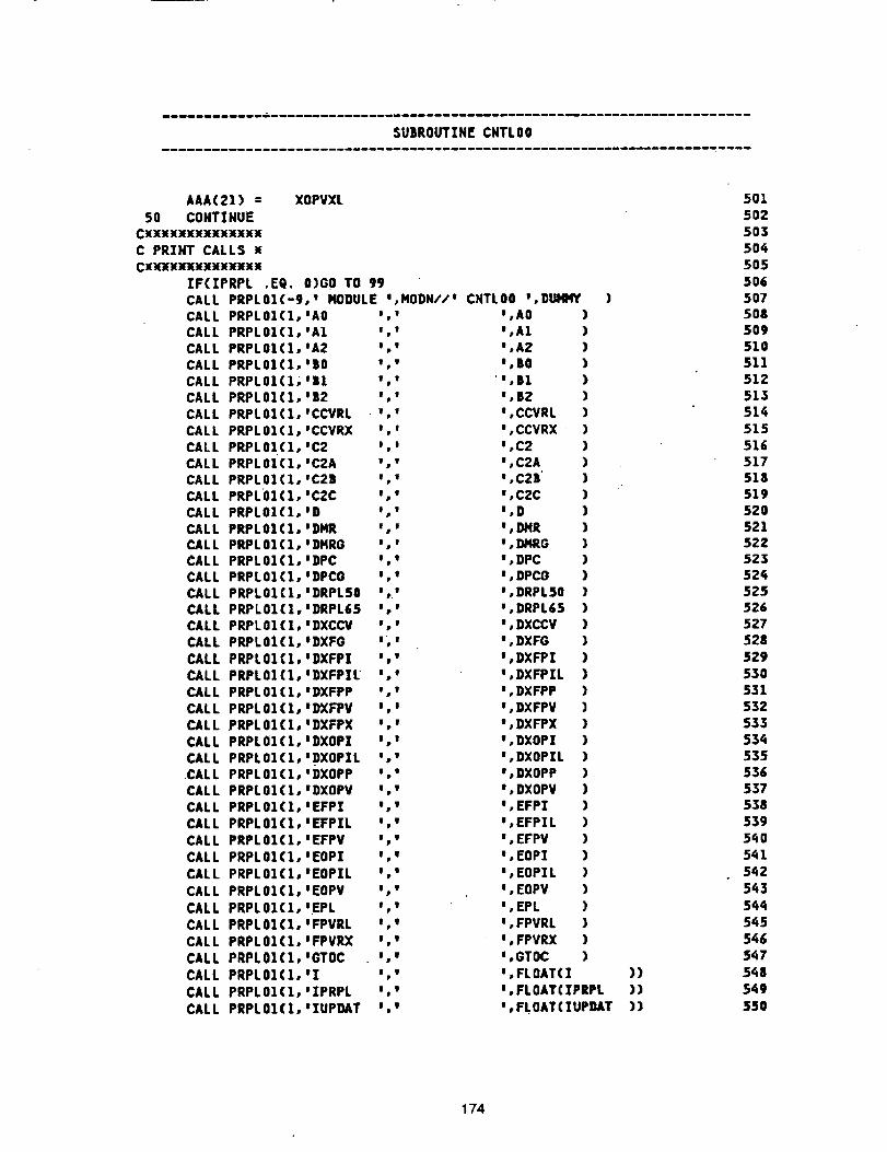
$UBROUTZN[CNTLO0
AAA(21)= XOPVXL50 CONTINUE
CXXXXXXXXXXXXXxC PRZHT CALLS x
C X )t':J(X X'J[ X )t3( X X_ _
]F(ZPRPL .EQ. O)GO TO 99CALL PRPL01(-9,' HODULE *,HODN.,"/t CNTLO0 w,DUI4HY )CALL PRPLOI(1,'AO .,1 I,A 0 )CALL PRPLOI(1,WA1 : . I,A 1 )CALL PRPLOI(1,IA2 ',' I,A2 )CALL PRPLOICI,'BO w w ',BO )CALL PRPLOXCX;I|X :,, "%B1 )
CALL PRPLOICI, IB2 ',' W,B2 )CALL PRPLOICI, mCCVRL ., , e,CCVRL )
CALL PRPLOI(1,1CCVP.X *,* *,CCVRX )CALL PRPL01(1,'C2 . . e,C 2 )CALL PRPLOICI,IC2A wow w,C2A )CALL PRPLOI(1,1C2B w i t,C2B' )CALL PRPL01(1,'C2C *,* %C2C )
CALL PRPLOICI,'D ',' I,D )CALL PRPLOIClo'DMR ',' ',DMR )CALL PRPLOICI,'DI4RO ',' w,DMRG )CALL PRPLOI(1,:DPC ',* ',DPC )CALL PRPLOI(1,tDPCO .,l w,DPC O )CALL PRPLOI(1,'DRPLSO . w I,DRPL$ 0 )CALL PRPLOl(1,'DRPL65 . t _,DRPL65 )CALL PRPLOI(1,'DXCCV low I,DXCCV )
CALL PRPLOiCI, eDXFO ,,e
CALL PRPLOI(1,'DXFPZ ','CALL PRPLOI(1,WDXFPZL ','CALL PRPLOI(1,WDXFPP ',*
CALL PRPLOI(1, tD'XFPV ',:CALL PRPLOI(1,:DXFPX ','CALL PRPLOI(1, IDXOPZ ',*
CALL PRPLOI(1, tDXOP]L I _CALL PRPLOI(1, wDXOPP ','CALL PRPLOI(1, eDXOPV . l
CALL PRPLOI(1,1EFPZ I,wCALL PRPLOI(1,mEFPZL w,,CALL PRPLOI(1,tEFPV .,w
CALL PRPLOI(1,|EOP] ',_CALL PRPLO1CI,wEOPIL I I
CALL PRPLOI(I, tEOPV I,*
CALL PRPLOI(1,1EPL ,,iCALL PRPLOI(1, wFPVRL ',_
CALL PRPLOI(I, IFPVP-X .,wCALL PRPLOI(1,1GTOC ','
CALL PRPL01(I, w] :,'CALL PRPLOI(I, wIPRPL Iol
CALL PRPLOI(1,e]UPDAT w I
J,DXFG )
',DXFPZ )*,DXFPZL )
I,DXFPP )w,DXFPV )',DXFPX )t,DXOPI )
*,DXOPIL )e,DXOPP )e,DXOPV )
_,EFP] )W,EFPZL )',EFPV )
I,EOP1 ):,EOPZL )
',EOPV )
',EPL )',FPVRL )
',FPVRX )',GTOC )
',FLOAT(] ))',FLOATCZPRPL ))
',FLOATCIUPDAT ))
5015O2
5035O4
5055065075O85O9
51051151Z513
514515
51651751851952052152Z
523524525526527528
529
530531532533
534535536
5375385395_0
541542
543
544545
546547
5_;8549
550
174
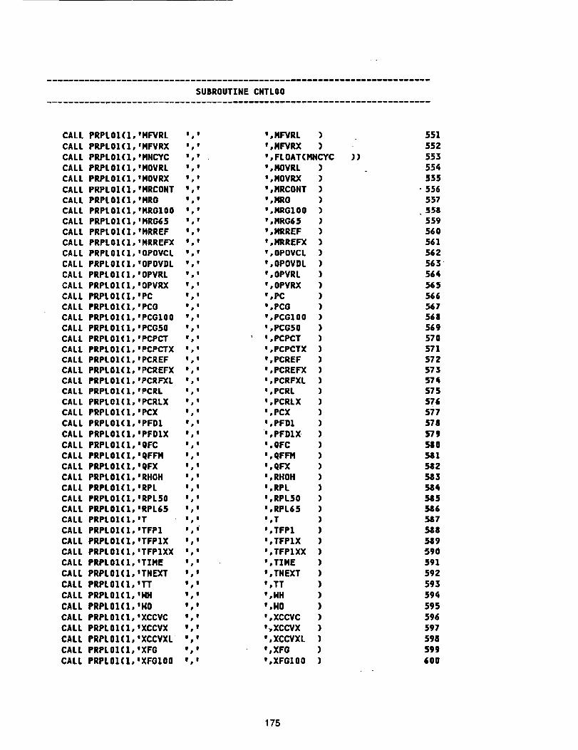
$UBROUTZNECHTLO0
CALLCALLCALLCALLCALLCALLCALLCALLCALLCALLCALLCALLCALLCALL
CALLCALLCALLCALL
CALLCALLCALLCALLCALLCALLCALL
CALLCALLCALL
CALLCALL
CALLCALLCALLCALL
CALLCALLCALLCALL
CALLCALLCALL
CALLCALL
CALL
CALLCALL
CALLCALL
CALLCALL
PRPLOI(1,'HFVRL J,'PRPLOI(1,'HFVRX J w
PRPLOI(1,'HNCYC I,vPRPL01(1 oHOVRL w t
PRPL01(1 wMOVRX v,IPRPLOI(loWHRCONT ! wPRPLOI(I,'HRO w vPRPLOI(1,'HRGLO0 o !PRPL01(1 IHRG65 %!PRPLO|(1 OHRREF . I
PRPL01(1 IHRREFX %1PRPL01(1 uOPOVCL g wPRPLOI(lowOPOVDL w,m
PRPLOI(1,'OPVRL w,IPRPL01(1 JOPVRX v I
PRPLO1(I,'PC m IPRPLOl(|,wPCO w,IPRPL01(1 IPCGlO0 w IPRPLOl(1, wPCG50 w,IPRPL01(1 tPCPCT w I
PRPLOI(lowPCPCTX w gPRPL01(1 oPCREF w,uPRPLOI(1, wPCREFX ",'PRPL01(1 JPCRI_L w mPRPLOI(lovPCRL w uPRPL01(1 wPCRLX . mPRPL01(l wPCX w,.
PRPLOI(loJPFDI o uPRPLOI(1,1PFDIX J,o
PRPL01(l wQFC I,.PRPLOZ(1 WQFFH m,mPRPLOI(I,IQFX t,m
PRPLOI(1.WRHOH .,mPRPL01(1 WRPL m IPRPL01(1 mRPL50 w iPRPLOl(l,ORPL65 o,IPRPLOl(lotT w,mPRPL01(1 .TFP1 w _
PRPLOZ(Z,WTFP1X w,IPRPL01(1 OTFP1XX g I
PRPLOZ(1 gTZHE m,oPRPLOI(I,ITNEXT m,I
PRPL01(l gl"T w,vPRPL01(1 114H o,o
PRPL01(l 1NO t,I
PRPLOI(I, gXCCVC w,wPRPLOI(1,1XCCVX w,v
PRPL01(1 IXCCVXL w iPRPL01(1 IXFG _,o
PRPLOI(1,'XFGIO0 e,u
_,NF"./RL )e,NFVRX )
_,FLOAT(HItC¥C_,NOVRL )°,NOVRX )
V,HRCONT )_,HRG )_,NIRGZO0 )_,NRG65 )_,IIIRREF )°,ICRREFX )
v,OPOVCL )',OPOVDL )
",OPVRL )',OPVRX )_,PC )
_,PCO )_,PCGIO0 )_,PCGSO )
' _,PCPCT )e,PCPCTX )
e,PCREF )e,PCREFX )
',PCRFXL )_,PCRL )t,PCRLX )',PCX )
',PFD1 )",PFDIX" )*,QFC )
_,QFFH )m,QFX )',RHOH )_,RPL )
_,RPL50 )e,RPL65 )_,T )
°,TFP1 )m_TFPIX )t,TFPIXX )
_,TZHE )t,TNEXT )
_,TT )_,HH )
_,NO )_,XCCVC )
t_XCCVX )_,XCCVXL )
_,XFG )
°,XFGIO0 )
))
55155Z
553554
555• 556
557558559560
561562
563'564565
566567568569
57057157257357_1575576
577578
579580581
58258358¢585
586587588
589590591
592593594
595
596597
598599
600
175
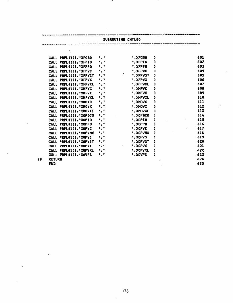
SUBROUTINECNTL00
99
CALLPRPLBI(1,IXFG$0 t tCALL PRPL01(lo'XFPZG w w
CALL PRPL01CI,IXFPPO .t
CALL PRPLBI(1,eXFPVC _ eCALL PRPL01(1,eXFPVST v,wCALL PRPL0|(I,IXFPVX v,_
CALL PR?LI|(1,1XFPVXL t .
CALL PPJPL01(1,tXHFVC %'CALL PRPL81(1,WXMFVX ','
CALL PRPLO](IoIX)IFVXL w w
CALL PRPL0|CI,IXI4OVC _t
CALL PRPL01(1,wX)IOVX w,wCALL PRPL01(1,tXMOVXL m w
CALL PRPL01(1,tXOPDCO w iCALL PRPL|I(1,eXOPIG t iCALL PPJPLII(1,1XOPPG w,m
CALL PRPL|I(1,1XOPVC I,ICALL PRPLOI(1,1XOPVHX w w
CALL PRI_01(1,'XOPVS .mCALL PRPL01(1,'XOPVST w ICALL PRIPLO|(1,'XOPVX w_
CALL PRPLOI(1,1XOPVXL I ICALL PRPLBI(1,tXOVPS w .
RETURN
END
I,XFOS0
e,XFPIG
',XFPPO
w,XFPVC',XFPVSTw,XFPVX
w,XFPVXL_,XMFVC
w,XMF'VX
w,XNFVXL
w_XMOVCI,XMOVX
t,XHOVXL
',XOP]X:O',XOPIG
I,XOPPOm,XOPVCI,XOPVHX',XOPVS
',XOFVSTJ,XOPVX
',XOPVXLw,XOVPS
601
602
603
60460S606
607
608609
610
611612
613
614615
616617618
619620
6216:':'623
t;24
625
176
AppendixD
T'I'BE Model Configration Input
The detail TTBE model described in this report was delivered to NASA-MSFC. Presented in
this appendix is the listing of the configuration input which the ROCETS system interprets to
generate the TTBE simulation without the control model.
177
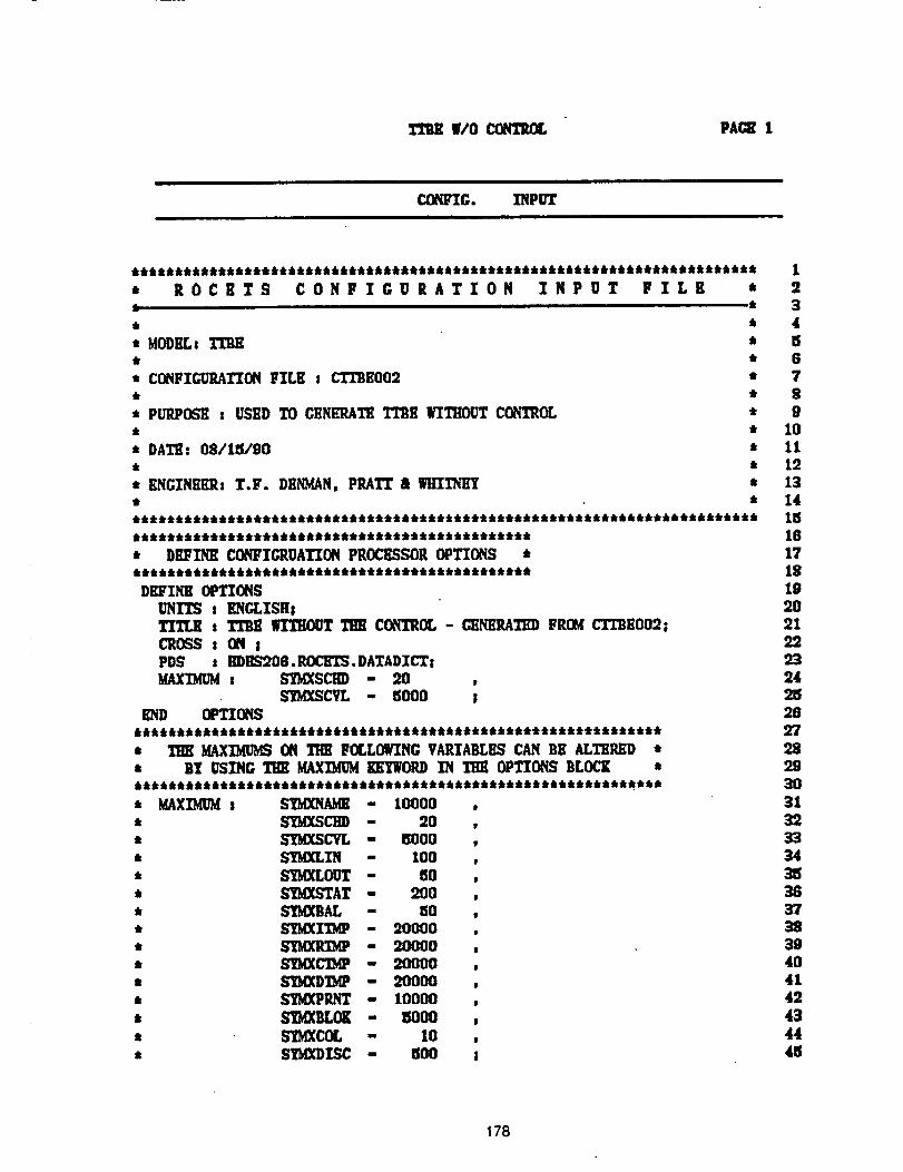
|/0 _ PACE !
CO_IG. INPUTI I
* ROCETS CONFIGURATIONk
Ik
* MODELs
t C(XqFI_RA_ FILE s CTTBEO02
* PUP.POSII t USED TO CENin_ATK TTBll WITHOUT CONTROL
* DATE: 08/1_i/90
* ENGZNEILq; T.F. DIINMAN, PRATT & WllI?h'l_t
INPUT FILB *ii ii •
t
_k
t
t
t
t
* D_l_q_ CONFIGRUATION PROCI_SSOR OPTIONS ***********************************************
DEFINE OPTIONS
_III_ t _ WITHOUT _ CO_TR_ - _NEI_D FROM CT_BEO02;CRO_S s ON IPDS s HDIlS_08. ROCETS. DATADICTsMAXIMUM t S'D_SCED = 9..0 ,
SYMXSCVL - _000 ;END OPTIONS
*************************************************************
* _ MAX][MIJblSON _ FOLLOWING VARIABLES CAN BE ALTIIRED *
* B1_USING THE MAXIMUM It'wYWORDIN _ OPTIONS BLOCK **************************************************************
* MAX_ m SYM_ - 10000 ,, SI_SCHD - 20 ,, S15g(SCVL - BOO0 ,, S'IMXLIN - 100 ,* SYMXLOUT - 60 ,* S_MXSTAT - 200 ,* _AL - ISO ,, S'_XI'D_ - :20000 ,* _ - 20000 ,, _C'IbtP - 20000 ,
t S_{XDI_P - 20000 ,, S_PP,._ - 10000 ,
* SIOVD(Br,._= I_000 ,, b"_COL - 10 ,• b"IMXDISC - _00 ;
1234tS6789
10111213141516171819202129.932421S2897289.93O313933343_3637383940414':'43444_
178
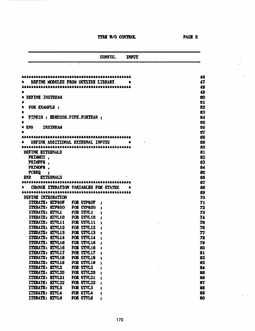
1TBE WO_ PAGE 2
I_IFIC. INPUT
DEFINE INTI_GP.ATION
ITERATE: illPBSF F02 UI"PIL_ I1TiI_TEs R_BSO F02 UTPBSO III_.ATR: H17LI F02 UTVLI zIIEltATK: !117L10 FOE U17LlO III1_,1Y: lI17LU FOR U17LII I
ITI_ATK: llTVLI2 FOE UTVLI2 I_I"K: EtTLI3 FOR U'ITLI3 sITE_I_: EITLI4 FOR U17L14 sITEP.ATE: EITLI5 FOR U17L15 IITRP,A1Y: !117L18 FOR UTVLI8 IITEI_TKs lll'VLI7 FOR UTVL17 sII"RP,AI'Es lil"VLI8 FOR UI'VL18 IITERATEs II_'VLI9 FOR UTW..19 I_TEs _ FOR UIVL:7. sWERATE: IG'VL20 FOIl UTVL20 ;I'I'EP,ATHs 11171,21 FOR U17L21 s_THs l_l'VL_l_, FOI_ _ sI"IIIP,ATRs KIVL3 FUR uTvr_ s_1_: iflTL4 FOR U17L4 ;IIE_TE: i!17_ FOR _ s
48474849
m)51626_n4_5156b'7
_L96O
6461566676'9697071
7374
7G777579gO81
83_4808687
899O
179
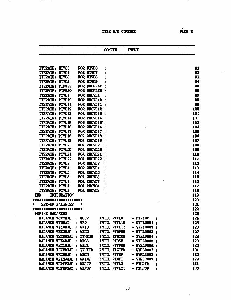
rme wlocoma: pAcE3
(_FIC. INPUT
ITE_TE: IITVL6 FORIIl_Al_: IffVL7 FORITERATB. 11171.8 MORI'D?.P.ATEs III"VL9 FOR_T_: FrPBS_ FOR_TEs PTPBSO FORF/_I'K s PTVLI FORITI_ATIZ s PTVLIO FORITirRATII: PTVLll FORII_ltAl"lh PTVLI2 FORITRRAI_ _ PTVL13 FORITERATEI PTVL14 FORITERAI_ z PTVLI5 FORITKItAI_ s PTVL16 FORI_RAI_: PTVLI7 FOQI_RATE: PlTLI8 FORIIERATE: P17LI9 FORIIEUI_: _ FORITRItAI_: PlTLgO FORITE_TEz PTVL91 FORITE2ATK: PTVL92 FORrIE'_TB s PTVL3 FORITERAI_: PTVL4 FORIII_AIY: _ FORITE_I_: _ FORIIY_IZ: P17L7 FORITl_A11h _ gORITERATE: _ FOR
E_ Igl_,ATIONttltt&tttt&i&i&_tttt&tt
• S_-UP BALANCES *
DEFINE BALANCESBALANCH IR:CVBAL : MCCVBALANCEwFgBAL _ W9BALANCEWIOBAL s WIOBALANCEY_C21BAL :
UTVL6UTVL7UI'VLBUT_RHDPBSgRIIOPB$ORHOVLI_:IOVLIOBIIOVLI1lhqOVLt2RHOVLI3IU_VLI4RHOVLISPJlOVL16RHOVLI7RllOVLI8RHOVLI9RHOVL9PJIOVL20
RHOVL9!R_OVL22
RE_L4R_f[3gROV[AR_OVL7_OVLS_OVL9
BALAN_ Ti_X1M)DALs TTHZOD
BAr_cH V_C_BAL : WHC8BALANCE_G1BAL : MtC1BALANCE TimBAL : X_D
BALANC_ _AL _ M_C5BALANCE WFXNJBAL : WINJBALANCE MIPI_PBAL : MIPFPBALANC_ MIPOPBAL : WHPOP
UNTIL PTVL9 - PTVLgC ;UNTIL PTVLIO - S"ZI_LO001 sUNTIL PTVLI1 - STIILO002 ;UNTIL PTOPRB - S_BLO003 !UNTIL TTHTOD - SYBLO004 IUNTIL PTOSF - SYBLO005 s.UNTIL PI"FPP,B - SYBLO006 !UNTIL TTHI'I_D - SYBLO007 !UNTIL PTFSF - SYBLOOOS !UNTIL FI_I - SYBLO009 l
-UNTIL PTVL3 - PTI:IPFD tUNTIL PTVL21 - Plr'KP_ s
919993949596970899
100101
I_10310410510610710810911011!112113114115116117118119120lol129193124
12612719.8
199130131132133134t31S
180
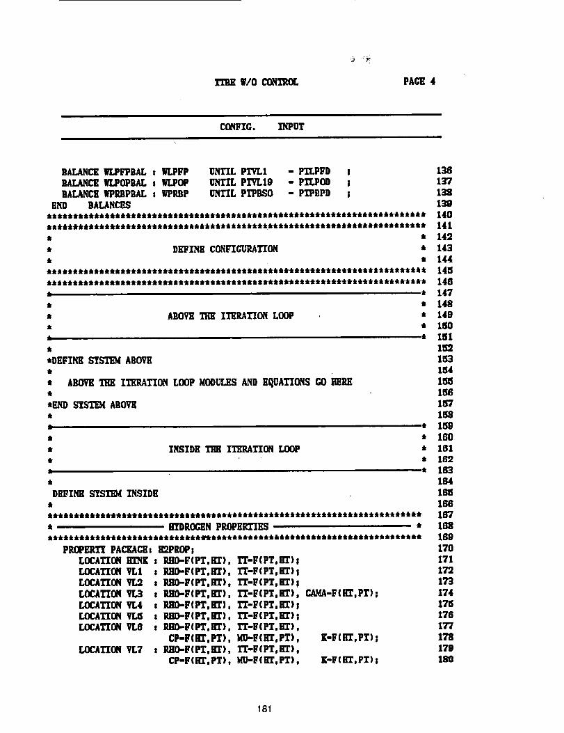
¥/0 CONTROL PAGE 4
CONFIG. INPUT
BALANCS WLPFPBAL t WLPFP UNTIL PTVLI - PTLPFD jBALANCE WLPOPBAL t WLPOP UNTIL PTYL19 - PTLPOD !BALAN£Y WPP.BPBAL: WPltBP UNTIL PI"PBSO - PI_BPD !
END BALANCES
• DilFl_qll CO_FZGURATION *k N
jjj Jt_:j_jjk_k_k_k_kjjjjttN_rj_k_j_:kJ4_J_ JJ_JJJJJJJJJ_JJJJJJJt_Jt_ J JJtJJJt_t
:tJkj:ktNtt_k_jNfkNjtttt_tJktNJjNtNttJtttNNtttt JJ_t_J_JtJJNJJJ_JJ_JJttkJ_iJJiJ
k •
t J
• ABO_ _ ITER_TIO_ LOOP *
i
*DEFINK ST_EM ABOVE
• ABOVKTHE ITRRATTON LOOP MODULESAND R_UATIONS GO HERS
_F.ND SISTSM ABOVE_k
fr
* INSIDE 111E IT_I_TIO_ LOOP_r
6
1361_7138
140141142143
14414L5148147148149180
1_4
1_581_561671F,8
* 1150* 160* 181t 182
LOCATION V_
LOCATION VL4LOCATION VY_5LOCATION VL8
PROPERTY PACKAGE: H_PROPjLOCATION KINg : PJIO-FIPT,gT), TT-F(PT,RT)LOCATION VLI : RHO-FIPT,I_), TT-F(PT, gT)LOCATTONVL3 t PJ_0-F(PT,HT), TT-F(PT, HT)
t PJII_F(PT,H_), TT-F(PT, HT): R]IO-F(PT,HT), TT-F(PT,nT): P310-F(PT,IIT), TT-F(PT,KI')t PJIO-F(PT.IIZ). I"T-F(PT.IlZ)
CP'F(I_,PT), MU'F(HT,PT)LOCATION VL7 t P.IIO-F(PT,R'r), TT-F(PT,i_)
CP-F{IIT,PT), MU'F(HT, PT)
I
I
I, CAMA-FIllT, PT)_
!J
8
, K-FIH_,PT)_
8
, K-F(IIT,PT)!
184
16IS166167t68169170171179173
174171_176177
178179180
181
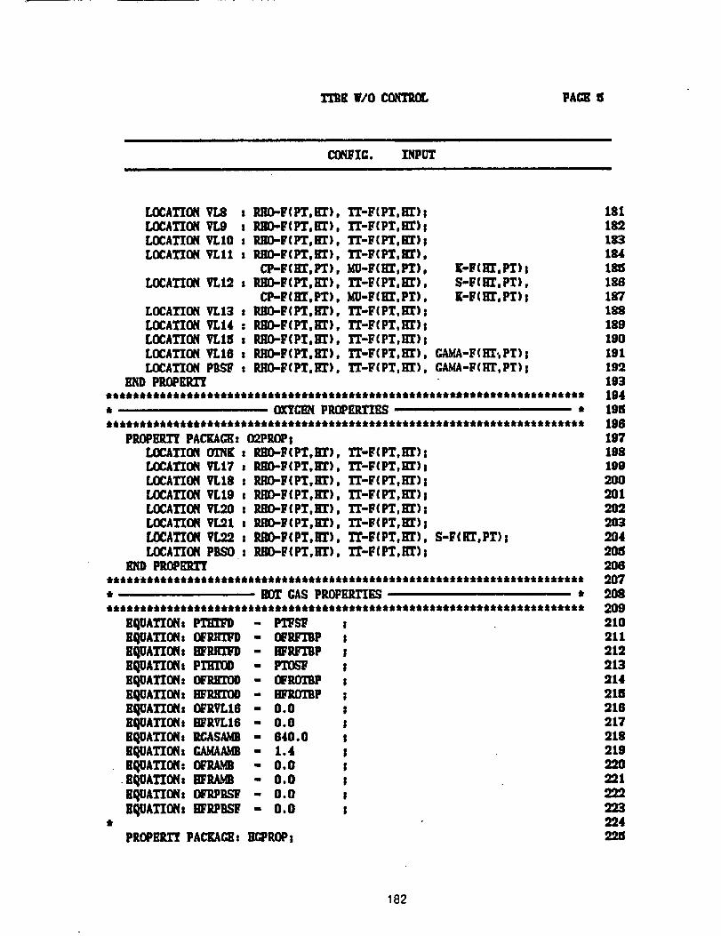
TI'BK W/O CON'I'_L PACE
CO_/_IC. INPUT
LOCATION VL8 t IUIO-F(PT, HT), TTuFiPT,HT)!LOCATION VL9 t P.SO.-F(PT, HT), TT-FtPT,m');LOCATI(Iq VLlO : _O-F(Ft, n'r), T_-F(PT,m');LOCATZONVLII t PJIO-F(PT,RY), TT-F(PT,nT),
CI_F(ITT, Fr), MU-F(I_,PT), r-F(Rr,Pl');LOCATION _,12 : P.SO-F(PT,_I'), T_-F(PT,In'), S-FtI_,PT),
CP-tT(Rr,Fr), MU-F(Kr.PT), i[-F(lrr. PT);LOCATION VL13 : RI_F(PT,I_r), I"r-F(PT.Rr)|LOCATION VLI4 : P.KO.-F(F_,IT_), TJ_-F(Fr,I_);LOCATION VI.15 s RITO-F(PT,ItT), IT-F(PT,lrr);LOCATION VLI6 s RRD-F(I_,Kr), I"I'-F(PT,Rr), GA_-F(ITr;PT)!LOCATION PBSF s RITO-F(PT.Rr). TT-F(PT, HT), CA.V.A-F(ITr.PT);
END PRflPERI"I
* O_C_ PROPERTIES ************************************************************************
P_PlglTt PACEAG_: 02PROPsLOCATION Ol?iK : RIIO-F(FT,IlT), TT-F(PT, HT);LCEATION _r.17 s P._-F(PT,KT), TT-F(PT,Rr)ILOCA_ON VLI8 : IUID-F(Fr,I_), I'T-F(PT, i;I')ILOCATION VLI9 : RRO-F(PT,I£1:), TT-F(PT,Rr);LOCAT'ION_I.20 : P.HO-F(PT,HT), TT-F(PT, ln')|LOCATI(M VL21t s RHO-F(PT,RT), TT-F(PT, Rr);f..OCATI(XqVL22 : RI_.F{PT,R'r), TT-F(PT, m'), S-F([r, PT);LOCATION PBSO : PJ_.F(PT,HT), TT-F(PT,I£r);
B31) PROPRI11_************************************************************************* _ GAS PROPERTIES *
EqOATIONs _ - P'_u"_ tEI_ATION: 13t'_ - OFRF'mP sEqgAl'ION: 8FRITTFD - I_RF_P ;EqUATIONs PTIIT_ - FTO_ ;EQUA_ON: O[_'RKI'_ - OFROTBP !EQOATTO_: _'RII_I)O - HFRO_P sEI_JATI(Xq: OFRVLI8 - 0.0 !El_lATIOtqt EI_RW..16 - 0.0 !EQOATI_s RCASAMa - 640.0 sEqOATIONs GAY,AAMB - 1.4 ;_qOA1'ION: OIZRA_ - 0.0
• I_qOATION: IIFR,Q_ - 0.0EQUATIONs OFRPD,_ - 0.0
stI_UATION, m;'RPIIb'T = 0.0 I
PROPBL_ PACKAC;I[sIE:PROPs
181182183lS418518618718918919019119"21931941951961971981902002012O2203
204905206
2092102112129139142169162172182199.20221
2222239249.25
182
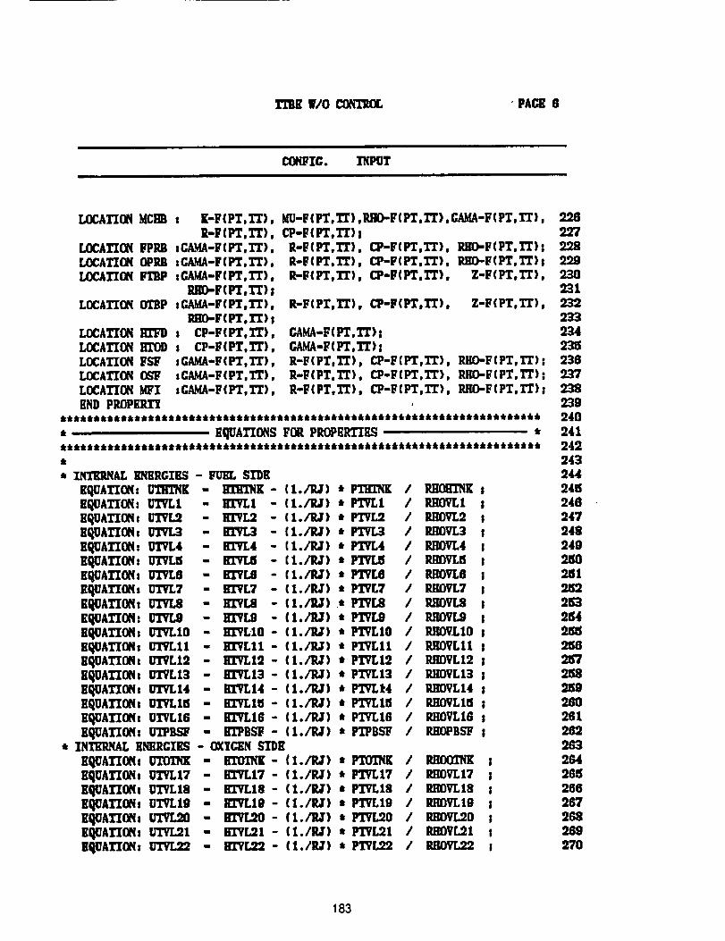
T13EW/O CONTROL • PACE 8
(_FIC. 13PUT
LOCATION MCHB : ][-F(PT,TT), MU-F(FT,_),]UJO-F(PT.TJ_),GAMA-F(PT,T£), 228E-F(PT.TT), CP-F(PT,TT} ! 22T
LOCATION FPRB sGAMA-F(PT,TT), R-F(PT,TT), CP-¥(PT,TT), RIIO-F(PT, TT)s 228r-OCATZ(_[ OP[_ :CAMA-F(PT,TT), R-F(PT,TT}, CP-F(PT,TT), RKO.-F(PT, TT)8 9.29LOCATION _ tGAMA-F(PT,TT), R-F(PT,TT), CP-F(PT,TT), Z-F(PT, TT), 230
Blff_F(PT,TT) S 231LOCATX(]q OTBP :GAMA-F(PT,TT), R-F(PT, TT), CP-F(PT,TT), Z'F(PT, TT), 232
imO-F(PT, TT) I 233LOCATION I[['FD t CP-F(PT,TT), CARA-F(PT,TT); 934LOCATION liX'OD : CP-B(PT,TT), GAMA-F(PT,TT); 23_LOCATXON FSY :GAMA-F(PT,T_), R-F(PT, TT), L"P-F(PT,TT), RHO-F(PT, TT); 236LOCA'X"ZONO_ tC.AMA-FtPT,TT), R-F(PT, TT), Cp-lrtPT,I"r), P.HO-I;'(PT, TT): 237LOCATION MFI :CAMA-F(PT,TT), R-F(PT, TT), CP-FtFT,X'T), P.H_F(PT,TT); 238END PROPEP._ 239
*********************************************************************** 240
, EQUATIONS FOR PROPEP._ * 241**,****,****,,ttllililillliii,,,tl****,,tiilltiiii******tiiliililiiit** 242, 243
* XN'I'EMNAL_ERG'rBS - FUEL $1"1)![ 244£QUATZON: UTRTNiC - ll]]_g - { I./RJ) * PTHI'_ / _K ! 248EQUATION: UTVL1 - HI"VLI - (l./P.,lr) * PTVL1 / P.,qOVL1 S 248RI_UAT][OSs UTVL2 - HX'VL2 - {l./P.,]r ) • PTVL2 / RHOVL2 ! 247E_ATI(_ t _ - I]I"VL3 - {1./ILT) * PTV[3 / IU]OVL3 ! 948E_0ATION: 0TVL4 - EI"VL4 - {t./RJ) * PI_.,4 / RI:R)VL4 ! 249E_ATXON: 0'I'VLB - BI"fL5 - { I./IU) * P_ / R[_0VL8 ! 21110Eq{IATZON: UTVL8 - BI'YL8 - { 1./P.,T) * PTVLfl / P.HOVL6 ! 251I[qUATXONs 0TVL7 - IGVL7 - (I./P._) * PTVL7 / P._VL7 s 9.152BqUATZON: UTVL8 - II:rVL8 - (1./11J) .* PTV[,8 / IuqOVL8 s 253EqUATXON: [TTVL9 - HI"VL9 - (1._) * PTVL9 / IUIOVL9 ! 284RqUATXOH: UTVLIO - EX'VLIO- (1./1_) * PT'VLIO / P,flOVLIO ! _5EqUATIONs UTVLll - KI"VLI1 - (1./P,J) * PTVLII / RIlOVLII s 21S8EQUAT'XONtUTVLlO - HI'VLI2 - (I./P.J) * PTVL12 / P..qOVL12 I 2_7EqUATXON8 U17L13 - Bl"VL13 - (I./P,J) * PTVL13 / IUiOVLI3 ; 258EqUATXONs UTVL14 - KX'VLI4- (1./IUr) • FI'TLt4 / P,HOVL14 s 2159RQUATZOHsUTVL15 - EI"VLI5- {I./P.J) * P'I'fLlll / P.HOVLlCi ; 260EI_JATZONt U17L16 - BI'VLI6- (1./P.,T) * PTgL16 / P.HOVL16 s 261RqUATXOHs U'I"PBSF - H'I'PBSF- (I./P.J) * FI"PBSF / P.HOPBSF I 262
* INTERNAL ENERGIES - OXYCENSI'DR 283
EQUATIOfls _ - _- (1./R;) * FI'OTHK / _K ! 2G4EqUAI'ZONs U17L17 - B17LI7- (I./P,J) * P17L17BqUATXONt UTVL18 - BX'VLI8- (1./l?,J) * PTVL18EQUATZONs UTVLIO - I_VT.,IO - (I./P,J) * PTPLlgEQUATION, U17L20 - i117L20 - (I./P.J') * PTVL20EI_ATXOflt u'rvL21 - IZ]LT[,21 - (I./P.J) t FITL2!EQUATION: _ - IGTL22 - (1./P,J) * Pl'VL22
/ RHOVL17 ; 265/ IU_VL18 ; 286/ RIIOVLIg I 267/ RHOVL20 ! 268/ P.HOVL21 s 26g/ BOVL22 ; 270
183
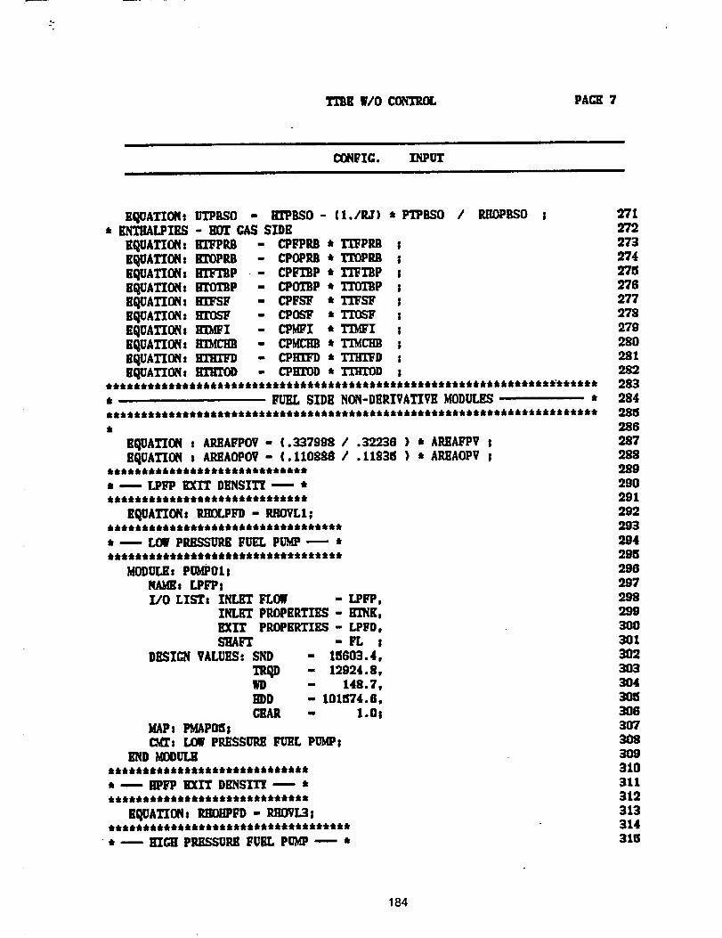
TIlIE W/OCONTROL PAGE 7
CON_ZG. ZNPUT
EQUATION• ITrPBSO - RrPBSO - (1./P,J) , PTPBSO / RHOPBSO• ENTI_LPIES - BDT GAS SIDE
EQUATION: BllePP3 - CPFPRB * TTFPM !EqOATION: ID'OPP,B - CPOPP,B * TTOPg3 sEQUATION, HTFI'BP ,- CPFTBP * TTFTBP lE_ATION:BTOI'SPE_ATION: KI"FSFE_ATION: I]I"_FEQUATIONs m_QlE_ATION:KIMCHBE_ATION:HI"I]_K_ATIONt_
- CPOIBP • Tl'O1'BP s- CPFb'_ • TI"FSF !- C1POb'_ • TI'OSF s- CPMF'I • TIMFI s- CPMCHB * TI'MCHB S- CPKI"FD • TI'KI'FD t- CPIG'OD •/'I"EG_ s
* -- , FUEL SIDE NON-DERIVATIVE MODULES •
N
EQUATION : AILEAFPOV- (0337998 / 032238 ) * APJ[AFPV !EQUATION s AILEAOPOV- (.110888 / .11535 ) • AREAOPV !
• --.- LPL?P EXIT DENSITI ---- •
EQUATTON: RKOLPFD - ILqOVLI|
• _ LOW PiUL.C_UP,K FUEL PUMP ,_' *j_iJillt_Jj_kjt_klllkj frttt _kt•ti•t_t_t
MODULE: PUMP01!
NA_s [.PFP !I/0 LISTs INLET FLOW - LPFP,
INLilT PItOPilRTIES - KINK,EXIT PROPERTIES - LPFD,
DI_IGN VALUES: SND - 15603.4,
TRqD - 12924.8,ND - 148.7,HI)D - 101574.8,CEAR - I .Os
MAPs PMAPO_;_: rOE P_E._L_UILEFUEL PUMP_
END MODULK
• _ HPFP KXI_ DIT,NS'rl'_ --.-- •• •_••••••••• Jk••lt _••_ _k_k•_k•••ft
EI_ATION: RIK)ilPFD - P,HOVL3
• -- HIGH PILI_SUI_ FUEL PUMP -'--- *
2712722739742752762772782'7928O281282283284285286:287288289290291292293294295296287298")993O03013O2303304
3063O7308309310311312313314315
184
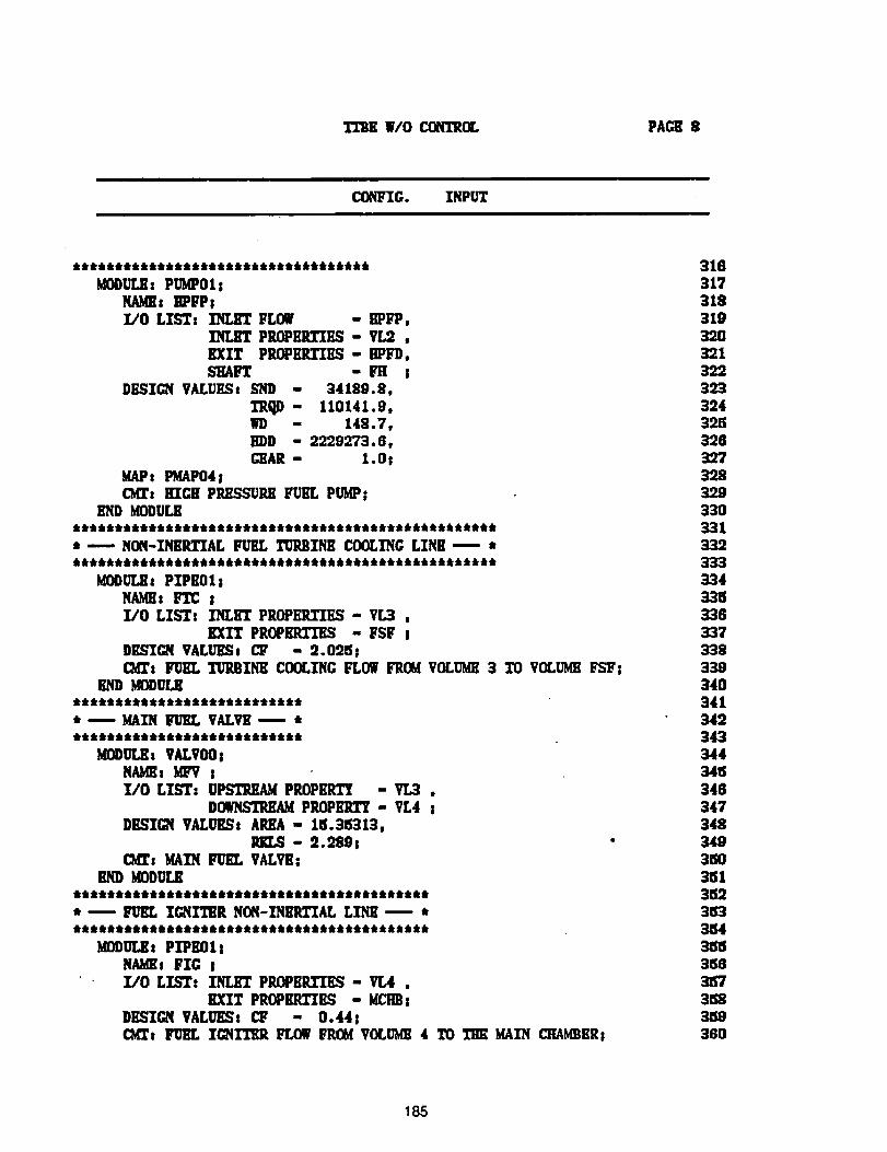
TEBK W/O COff'_OL PAGE 8
CONFIG. INPUT
t kttli_tktt:k &tit a,t_:ktk:k t 6:klk_ tttkttttt
MODUr_: PIblPO1 sNAMll: mFPII/O LIST: INLET FLOg - HPF'P,
INLET PEI_EP,.TII_ - vr_.,EXIT PROPERTIES - EPFD,SHAFT - FH I
DESICN VALUKSg END - 34189.9,
I'RQD - 110141.8,WD - 148.7,EDD - 2229273.8,GIAR - 1. Os
MAPs PMAP04 j(Mrs KIGH PP.HSSUREFUG'L PUMP!
END MODULE:lk_kt tttikttktk tkt:lk:lklk'k:lk tk:k:kt tt _ _ tt ttktt_ tit _tt_ttt_tt_ tit
* ---- NON-INERTIAL FURL TURBINE COOLING LINE ----' *
Id_UL_: PIPE01!NAMH: IVL'C !I/O LIST: I'_ET PROPER.TIES - V[3 ,
EXIT PROPBRI'IRS - FSF jDESIGN VALUESt CF - 2.02IS !CM_s FUEL TURBINE COOLING FLOW FROM VOLUME3 TO VOLUMEFS'F:
END MODULE
*--.--MAIN _UBL VALVE .---- *
MODULEs VALVO0sNAMEs _ !I/0 LIST: U_ PROPER1"/ - VL3 ,
DOWNSTREAMPROPKR_ - VL4 jDESIGN VALUE.St AREA - 1tS.36"313,
- o.9f_9!CMZ: MAIN _ VALVE_
END _ODULE******************************************* ----' FURL IC_ITER NON-INKP,TZAL LINE _ *******************************************
MDDUY.._t PIPEOI !NAMEs FIG j
* Z/O LIST: INL_ PROPBP.ZIF_ - VL4 ,
EXIT PROP_TII_ - MCItBsDESIGN VALUESt CF - 0.44 IC_l's Fu_. TC_IT_ FLOW PRad VOLUgE 4 TO Tm_ gAIN C_ER!
316317318319320321322
32439.._32832739.832933033133233333433_33633733833934034134234334434tS346347348349
3513523153354315153_8
3_83_93130
18,5
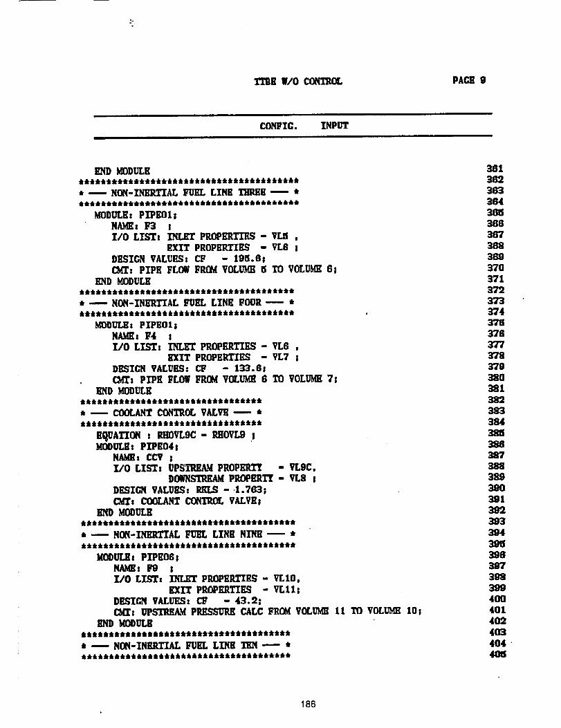
TTRE W/O CONTROL PAGE 9
i lill
CONFIC. INPUT
END MDDULE_kttJttk 4,it tk4,4,titkttktk *tit*tilt* _t_ttt*ttt_t_
t ---- NON-_AL FUEL LINE THREE----
MODULE: P_EOlsNAMEs 1_ II/O LIST: INLET P_E_ - VLa ,
EXIT PROPERTIES - VL6 sDESIGN VALUES: CP - 198.6 !C_z PIPE FLOW FROM VOLUME _ TO VOLUME 6!
E,ND MODULE**************************************** ---- NON-I_ERIIAL FUEL LINE FOUR- *eee,eeeeee,teeeeeee**et,e,eeeeee,,*****
MODULE: PIPEOl|NAMEs F4 II/O LISTs INLET PP,OPKi_KS - VL6 ,
EXIT PROPERTIES - VL7 s
DESIGN VALUES: C_ - 133.8 !C_T: PIPE FLOW FROM VOLUME 6 TO VOLUME 7s
END MODULEIklllk_li*i_e &llt4bi*lli*li_*lle*_
* -- COOLANT CONTROL VALVE -- ***ee,%e,e%**eee%e,_,eee,%%,_eeeee
E_A_ s RHOVLOC- RIIOVL9 !MODUL_: PIPE04 s
NAMEs CCV sI/0 LISTs UPSTREAM PROPEI_ - VLgC,
DOW_STRREq PROPERTY - VL8 IDESIGN VALUES." RKLS - .1.793 !C3dT: COOLANT CONTROL VALVEI
END _ULE**************************************** -- NON-INERTIAL FUEL LINE NINE -- *
MODULEs PIPE08 sNAMEs F8 II/O LISTs INLET PROPERTIES - _LIO,
EXIT PROPERTIES - VLl18DESIGN VALUES: CF - 43.2:C_: UPSTIULA_ PRESSURE CALC FROM VOLUME 11 TO VOLUME lOs
END KODULE*************************************** ---- NON-INERTIAL FUEL LINE TEN --- t
38138238336436_36836736836937O3713723'733"/43783763773783793803813823S338438_;388
38838939O39139239339439_39639739_3994OO4014024034044O8
186
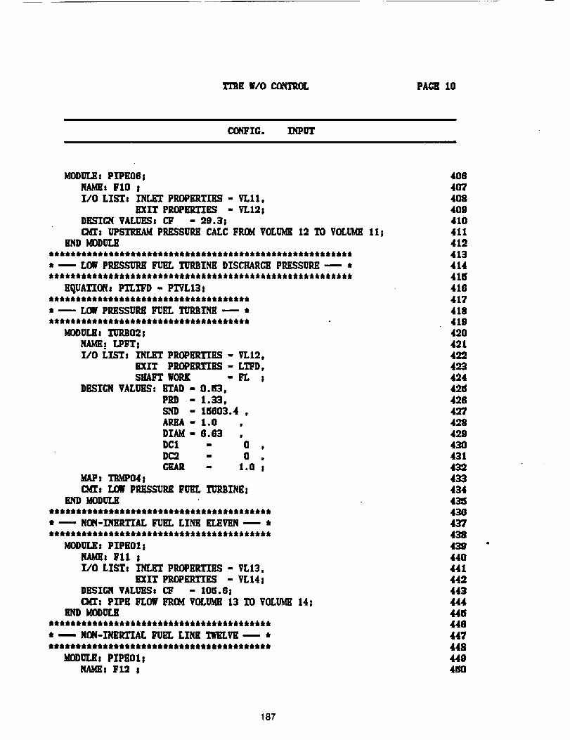
TI'Bil 11/0 CONTIUI, PACK 10
C(_IFZG. XNPUT
is gl0 s
EXIT P__ - VLI28DESIGN VALUESs CF - 29. _8Od_: UPSTREAM PIU1SSURll CALC FROM VOLUME 12 TO VOLUMEIll
END KODULE
* '---- LOW PP,I_;SUI_ FUEL TURBINK DISCHARCE Pi_SSUP, II _ *********************************************************
KI_UATIOfl_ PTLTF'D - PTVL131*************************************• _ LOWPRESSURE FUEL TURBINE --- tttktkt_kft Ik6dk 61ktik 6 dkdktkt:lkldk dktdk'dktkttttttltttt
KODULSt TUP_021NAMH! LPFT|_0 LISTs I_ P__ - VLi2,
EXIT P_K_ - L_D,SHAFT WORK - FL 8
DESIGN VALUESs grAD - O. tl_,
PRD - 1._,- 1_8_.4 ,
AREA - l.O ,DIAM- 8.63 ,DCI - 0 ,D_ - O .CIGAR - 1.0
MAP_ TBMP04 scKr: LOW PRESSURE FUEL TUP,3INEs
END MODULE*****************************************
t _- NON-I"NSRTXALFUEL LINK RLKVIY.N_-. ******************************************
MDDULEt PXPEOl !NAME: _lI !
_ PRGPKR_ES - VL141DESIGN VALUESs C_ - 10_. 8 !CM_: PIPE FLOW FROM VOLUME13 TO VOLUME141
END MODULE
• _-. NON-I'NERTIAL FUEL LINK TWELVE_- *lill Ill tltllittlt It lltt tttl ill tllttllt lit ti it i tl t _ ttttt tl t tttttl t I
MODULE: PlPlOllll,4lltlli F12 li
4084074O84094104114124134144154164174184194204oi40o4234244_5428427428429430431432
4_44_54_64_743843944044144244_444445448447448449450
187
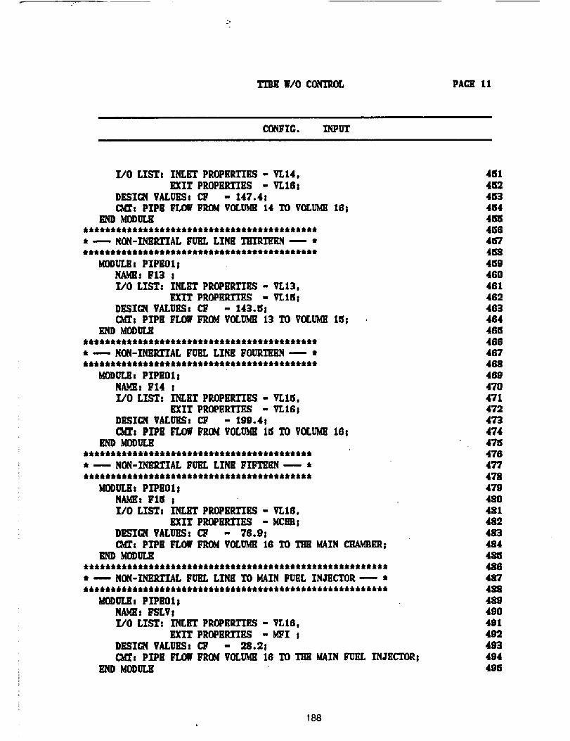
.-o
W/O CONTPJ]r, PACE 11
CONFIG. INPITr
I/0 LISTs INLET PROPERTIES - VLI4,
EXIT PROPERTIES - VL181DESIGN VALUESs CF - 147.41£M_t PIPE FLOW IqZOg VOCU_ 14 TO VOLU?val18!
END MODULE*******************************************•' ---. NON-]$HnLTIAL FURL LINE TrrzRTERN ----. *t_ttt d_drti6_kdkd_tdktJktdt_k_ttt_tt_tttt t _t _t_Q_t
MODULEs PZPEOI sl: Y13 sl/O LIST: INLET PEOPRILTIES - VL13,
EXIT PP.OPER.TIES - VL15!DESIQi VALUES: CF - 143.5 IOM_: PIPE FLOW FROM VOLUI_ 13 1'0 VOLU_ 15; .
END gODULE*******************************************• -.--- NON-_AL FURL LINE FOURTEEN m ,
MODULEs PIPE01 sNAME: F14 II/0 LIST, INLET PROPERTIES - Vrl_i,
EXIT PROPERTIES - VLI61D_IGN VM..UI_s £T - 199.4I_: PIPE FLOW FP.CM VOLU_ 15 TO VOLIbf_ 168
******************************************• ---- NON-_Ar- FURL L1NE I;'IFT_EN -- *
KOOULEs PIPEOlsi: F15 jI/O LZS'Ts ZN_ PROPEILTII_ - VLIG.
DEEII_ VALUES: CF - 76.9s_: PIPE FLOW FROM VOLUME IG TO THE MAIN CHAMBER;
END MODULE
• --'-- NON-INI_ZZAL FURL LINE TO MAIN FURL INJECTOR _ *
MODULE, PZPB01!NAME: FSLVsI/O LIST: INL_I' PROPERTIES - VL16,
EXIT PROPERTIES - MFI s
DE_;IQI VM.UES: C_ - 28.2!Cbll': PIPE IL_OWFROM VOLL_4E 16 TO THE MAIN FUEL I'N,TRCTOR;
END MODULE
481
45245345445545845745845946046146246348448n46848746-8489
470471472473
474475476477
47847948o4814824834844854884874224894904914o2493494495
188
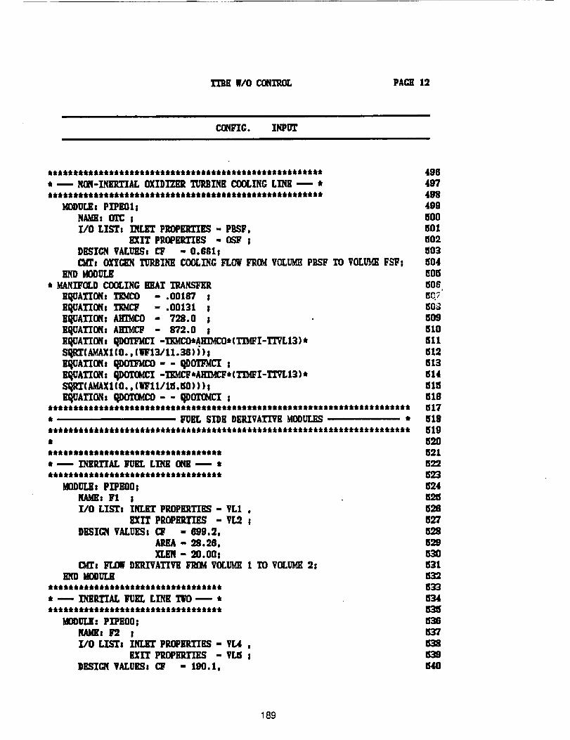
I'£11E WlO CONI"IOL PACE 12
CONFIC. IMIUT
****************************************************** 488i --- NON-INEETIAL OXIDIZER TUP,BI'NE COOLINGLXNE_ * 497****************************************************** 498
bIODULEsPXPEO18 400NAI_: 01"C j 1500I,/0 LISTs ZN[,]_ PROPERTIES - PgSF, 601
EXIT PROPB_PXES = O_ ; 1502DI_'qlCN VALe, CF - O.GGII 803C_rt OXYGILqTURBINE COOLINGFLOWFROMVOLl.r_ PBSF TO VOLUMEFSFI 804
END MODULE _OEi* MANZFOLDCOOLINGBIiA_ TRANSFKR t506
EqOATIONt TEM(_ - .00167 I e_7£I_UATION, TiOACF - .00131 ; _0_EqUATIONx AI_MCO - 708.0 ; 509EQUATION: AliIblCP - 872.0 ; 810EQUATIONt ql)OX'Ir_I -TZMCO*AHZ?,_O*(TI'MFI-TrVL 13) * 811S'qI_(kMAXI(O., (WF13/11.38)) ); Ell2EQUATION, _-- O.D_ ; t!13liltUATIONI qDO'£(iICX -_D,tCF*A_F*(TIbtFI-l'TVL13 )* 514sllzc x1(o.. (wit/re.so)))seq Aiz , qnoilllco-- qnimlicz s nlS
*********************************************************************** 1517
tt FUEL S][DB DERXVATIVRMOliULES • 518tltllilttttitttiititiliiiliitiiiiliiiitiitittititittttttillititiitillit 519ii 520lttttt t, lltltltttittlrtlttttttti, lttttt ,tl **ti, i, ,it t, 521• _- INKR.TIAL _ LINE ONg _ t 522
llODUr.ll: PIPE'O0i _24NAMEsFI II/O LTS'Tt INLET PROPERTIIL'q= VLI , 526
EX1T PROPERZ_S - VIi ; 827DESIGN VALUESI CF - 6'99.2, _28
AREA - 28.')8, 529XLEN - 20.008 530
(_l _ DEIZVATIVB FROMVOLUt_ I TO VOLUME2i 531EIID MIOOULE li31
i --- ZNIIII'ZAL FUEL LINK _NTO_. *tttttttktlttttttttttttttttttttlti ttltttttttttt
MO00_: PXPIO0; _36
X/O _i _ PP.OPI?,I"ZES- VL4 , 638BXIT PUOPEIZXi_ - VL5 i 639
DBSIGN VALUES1 CY - 190.1, 540
189
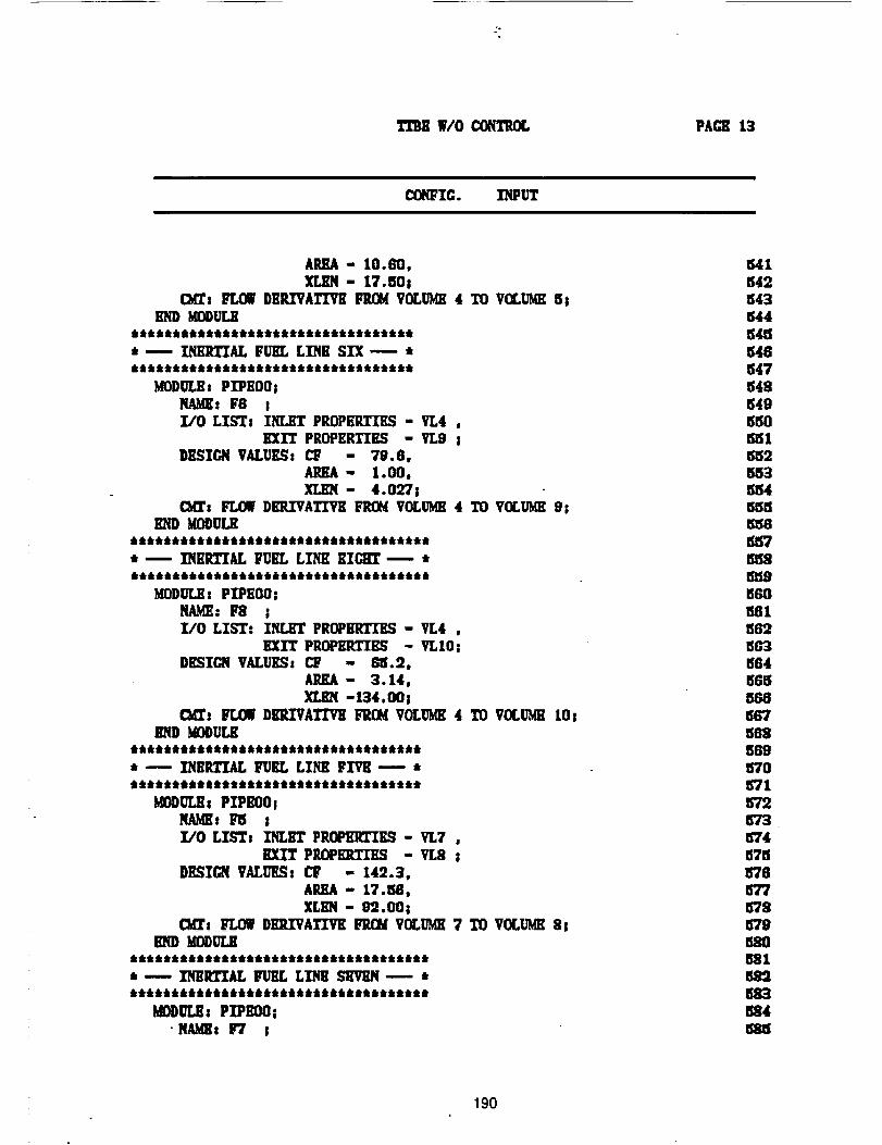
Tn_ W/O COh"EROL PACE 13
C08FZG. INPUT
AREA- 10.60.XLEN- 17.50s
C_s FLOW DERIVATIVE FitlY/VOLUME4 TO V(]LUgE 5sEND KO/)UL,E
N_/k Jtj_N J_J6 JNtJl/N J J/kttfkJJJ JJJi_k JN
*---- INERTIAL FUEL LINE SIX--_ i
MODULEs PIPEOOsNAME; F8 IZ/O LISTs INLI_ PROPBRTZKS - VL4 ,
EXIT PROPERTIES - VL9 !DESIGN VALUESt CF - 79.8,
AESA - 1.00,XLEN - 4.027!
CMT: FLOW DEILI'VATTVBFIL'CMVOLUME4 TO VOLUME9sEND MODULE
,- INERTIAL FUI_ LINE EI_- i
MODULEt PIPEO0.NAME: F8 !I/O LIST: INLET PROPBRIIES - VL4 .
EXIT PROPER_IIS - TLI0_DESICR VALUES_ C_ - b'_.2,
AP,_ - 3.14,xr_q -134.00!
CMZ: FLOW DERIVATIVE FROM VOLUME4 TO VOLUME IO_END gODULB
* -- INBILTIAL FUEL LINE FIVE- •
***********************************KODULE: PIPEO0 !
NAME: _L"O LIST: INLET PROPERTIES - VL7 ,
EXIT PROPERTIES - VL8 8
DESIGN VALUES: CI_ - 149.3,AREA- 17._8.XLIIN - 99.00_
O,ITs FLOW DERIVATIVE FROMVOLUME7 TO VOLX,_ 8sEND MODOLB
ti tlltll Ililli tt tlillltll tttlll ill ill Ilitlllt ill Illtll ill t t t t t t t t t t t t t t t t
II ---- INERTIAL FUEL LZNB _---- tt************************************
I_ODULE: PlPEO0:-NAME: 117
e1411s421543
tS4tS648t147t_48tS49B_O551IS52t153_114lSISllE;_;8
llb'7mS8[1119elSO
lib'266386466tS_681S67
_68569b'705711572
b'74_,el678t177_78_79E_O581
584mltS
190
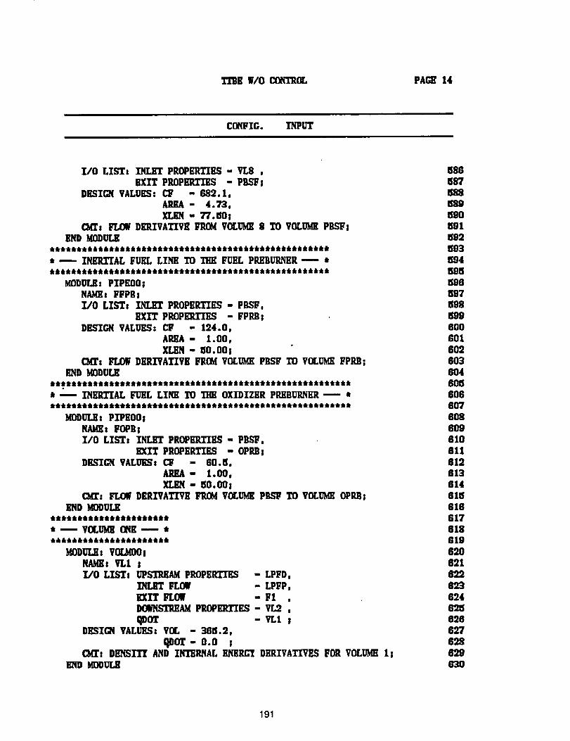
TTIIBW/OC(IqT2_ PACE14
CO_IG. INPUT
I/0 LISTs INLETPROPERTIES- VL8 ,HXITPROPERTIES- PBSFS
DKSIGNVALUKS:CF - 682.1,ARIA - 4.73,XLIIN - TT.aOI
C_s FLOW DmlIVATIVK FROg VOLU_ 8 TO VOLOlll PilSUIBND MODOLK
• iitt•tittti•i•titttitt•t• it•tilt Qttlttltttttttlltlttlttt&tt•
• .---- INmITIAL FUEL LINK TO TItK FUEL PR/IBURN_R- Irtt tt ltttt t ttl.tttt titt tt ti i, ill it, 41tldlti tilt•tilt •tttttttttttt t• t t t t t• t
MODULK: PIPliO0;NAlals FFPBz
I./0 LISTs INLET PIOPEITI_S - PBST,EXIT PROPERTIES - FPRB;
D_gIGN VALUES- CF - 124.0,AREA - 1.00,
XLEN - 50. O0 !c_r: FLOW DiiP.XVATIVR FRObi VOLUMEPB_ TO VOLUMEFPRB;
END IIODULll
• ---- INKRTIAL FUEL LINK TO THE OXIDIZER PILEBUILNER---- •lltltllt It tl tt Illtt IIlt 'll tttll •it ill tlltltlltttll _ tl _ t _ tt i t _ _ t tit i• t itt i _ i itt k i tl • t t
MODUL_: PlPlOOiNAME: ¥0P88UO LISTI INLET PROPBP._I1S - PIlS_,
BXI'_ PROPI]RTIBS - OPRB;DIL_ICN VALUESt Ctz - 611.el,
AREA" 1.00,XL_ - _O.OOI
CM_ FLOW D£RIVATI'Vil FP,_ VOLibl P_ TO VOLUMKOPlUl;SliD MODULE
• • lit • • tt • • ill • ill ill ill • ill ill tit• • Ilttll •
•----VOLUM_ ONK--- *tl Ill lit ill ill ill ill ill Ill ill ill ill Ill lit ill ill tlltll ill ill • •
KODULli: VOiLIO0i
NAME: VI, I iI/0 LISTs UPSTREAM PROPERTIES - LPFD,
INLRT FLOW - LPFP,EXIT FLOW - FI ,DOb'NST_AM PROPEI_IES - VL2 ,qDOT - VL1 ;
DESTCN VAr-UKS: VOL - 36el.2,qOOT- 0.0 s
C_i DENSITY AND I_AL BNKRCYDKRZVATIVHS FOR VOLUMH11Bill) MOOULE
58868758858959O6915925035945955966975995998006016026036O46O56O66O7608609810611612613614815GIG61761861969O621622823
62462562662769.862963O
191
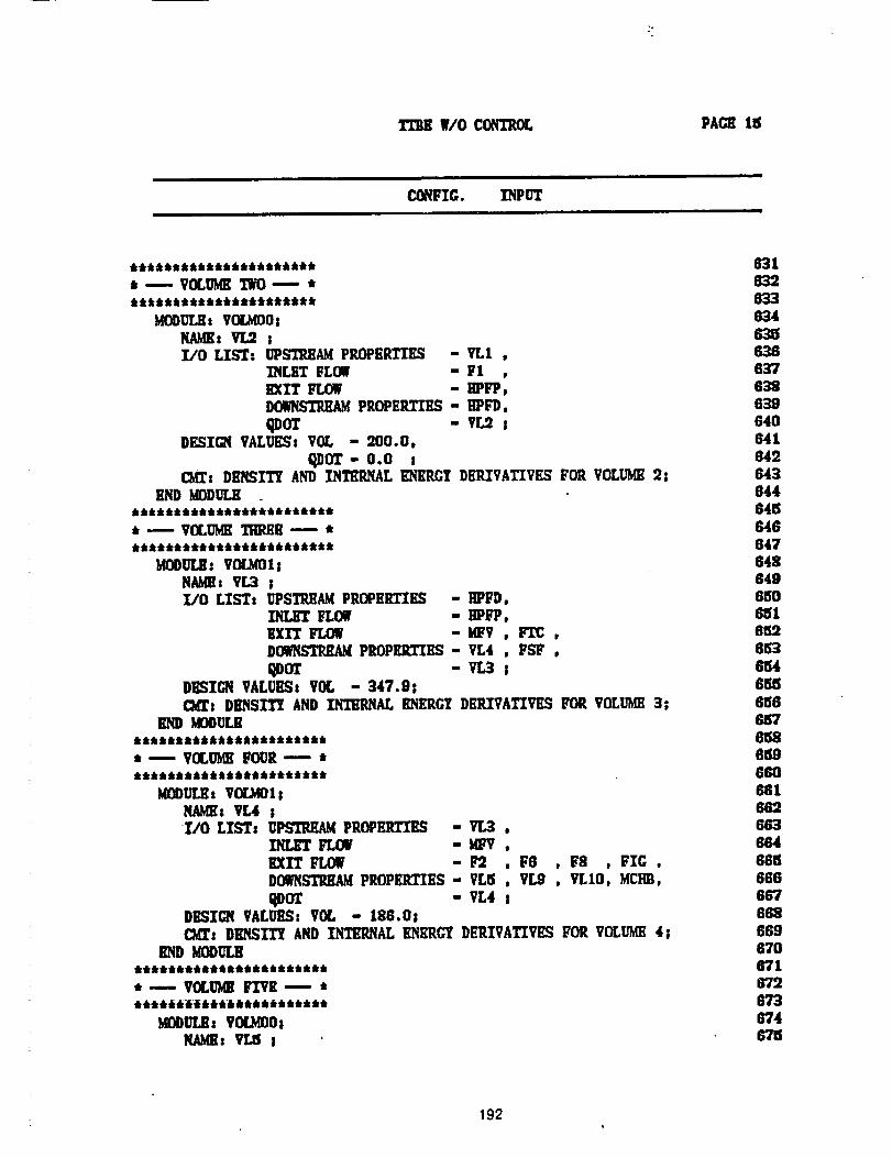
PACE IS
i n i
CONFIC. INPUT
* _ VOLUMETWO--- ,
MODULR: VOl_OOsPLU(Ez VL2 ;I/O LIST: UPOn, HAM PROPERTIES - VLI ,
INLBT FLO_ - FlEXIT FLOW - _FP,DOWNSTREAMPROPERTIES - HPFD,
-vr ,DKSI_ VALUES: VOL - 200.0.
O.J)OT- 0.o s_: DENSITY AND INTKRNAL KN£RGY DKRZVATIVRS FOR VOLUME2;
END I_DULR
* -- VOLUgE THP_II -- *
MOOULK: VOLMO1sNAME: VL3 ;I/0 LISTs UPSTI_Ag PROPERTIES - ilPFD,
INLET FLOW - HPFP,BXIT FLOg -MFV , _ ,D_ PROPE]_]_- VL4 , FSF ,
Qoo -w.,3 sDBSICN VALUESs VOL - 347.9;C_: DENSITY AND INTERNAL EH£RCT DERIVATIVES FOR VOLUMH3;
END gOO_l.nkt:k:k &:k _,:kt6:k:kttttt4,:k _ :k_k6
t --- VOLUMEFOUR--- ,***********************
_ODULE t VOLMOIsNAMEs VL4 ;I/0 LISTs UPSTI_._ PROPEP.TIES - VL3 ,
INL_ FL_ .-MFV ,EXIT FLOW -F2 , F6 , F8 , FIG ,DO_STEHAg PP.OPEI_'IES- VLtS , VL9 . VLIO, MCHII,
qDOT - VL4 ;DICtiON VALUES: VOL - 18G.O;
C_: DElqSXT_ AND llqTEP,NAL ENERGY DERIVATXVRS FOR VOLUMI_4;gODUL_
************************ ---- VOLUMEFIVE ---. *
baM)ULE: VOLMO08NAglgs VLI5 I
63163263363463863G63763B63964O641649643644648646847648649680
6_
6546_86866676'15868966O68166266366466156666676886696'706"71
67367467B
192
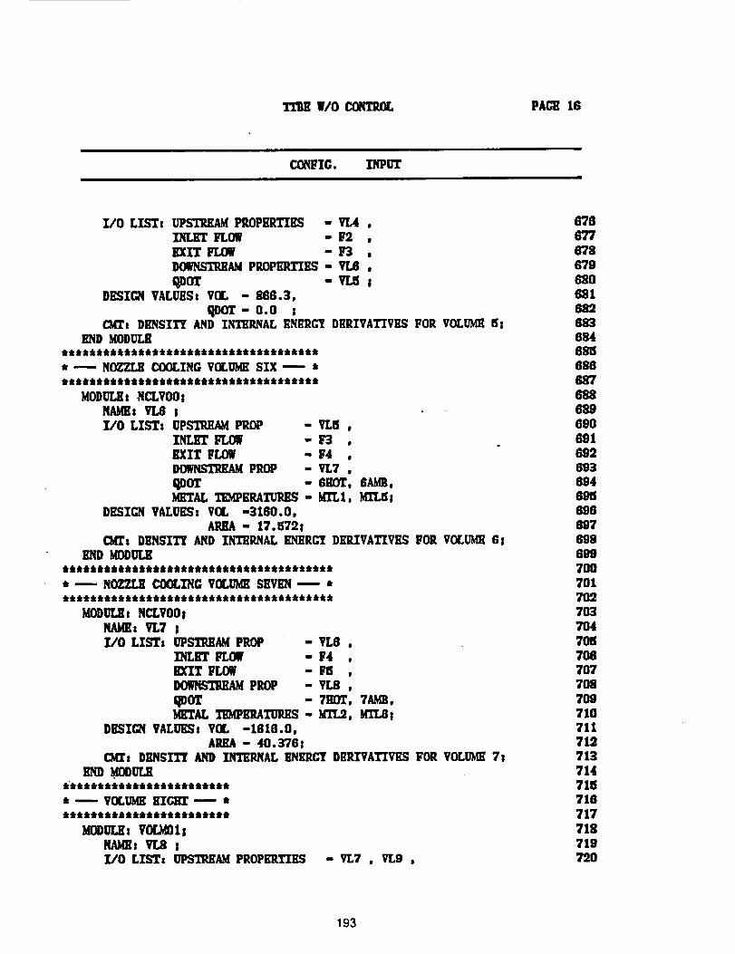
TI'BE W/O CONTItI_ PAGE 18
CONFIG. INPUT
7./0 LISTz UPSTI_Ag PROPERTIES - VL4 ,INLET gLOW - F2 ,EXIT FLOW - l_ ,DO_qSTIU1AN PROFIt.TIES - VL6 ,
qDOT - VI.n !DESIGN VALUESs VOL - 868.3,
qDOZ- 0.0ClOt DENSITY AND INTERNAL ENERGY Dii'R_VATIVES FOR VOLUME51
END MODULI_t:k k :ktkk Jkkt4, tkt_k:kttlklkt_Q tktt_tttt_tkttt
* ---- NOZZ_ COOLING VOL[ba_ SIX --.- *
MODULEt NCLVOOzNAMEs VL6 !l/O LIST: UPSTREAM PROP - VLB ,
INLET FLOW - _ ,EXIT FLOW - F4 ,DOWHSTI_AMPROP - VL7 ,
I_DOT - 6EOT, 6AGE,METAL TEMPERATUIUIS - KI'L1, MZT_s
DESIGN VALUESs V(I, -3160.0,APJU - 17. E172S
ChiTs DENSITY AND INTERNAL ENERCT DllR.IVATIVES FOR VOLUgE GsEND MODULE
tklkilk tkkt:k k:k tkk kikt k_kklkik_tttktttttk_kkt t k •
., -- N0_ZLE COOLING VOLUMKSEVEN -- *tktkk:kttktktk k a,:k a, tk&t:ktiktk_kt_k_tk#tkttkkk kkt
MoDur_ I NCLVOOI
NAMEs VL7 sZ/O LISTs UPSTREAM PROP - VL8 ,
INLET FLOW - F4 ,EXIT FLOW - I_S ,_AM PROP - VL8 ,
qDOT - 7HOT, 7_IB,METAL TEMPERATURES- MTL9, KIT.B!
DESIGN VALOESs VO[, -1616.0,AREA - 40.376 !
C)_ DENSIT_ AND INTERNAL _N£RC'_ DERIVATIVES FOR VOLU_I 7_
I_tkk _Ikik:k &_kktttkttk 4,tktk tl_k _ _ k
* -- VOLUMEKIC:HT----- *ttiitiltitiiiiiiiiitttit
_OOOLE: VOL_IINAZi VL_ _Z/O LIST: UPSTREAM PROPERTIES -VL7 , VL9 ,
676677678G7968O681682683684681_688687688689690691692693894Gg_6966975"986997OO7017O27O37O4701el7O67O77087O971071171:371371471_i716717718719720
193
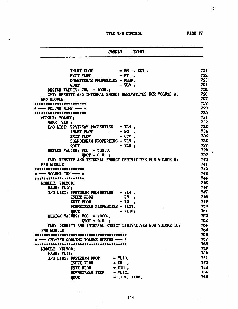
PACE 17
ii
COP/FIG. INPUTi i
INLET FLOW -F_ . CCV.EXIT FLOW - F7 ,DOWNSTREAMPROPlmTXES - PBSF,
qDOT -VLS sDESIGN VALUESs VOL - 1000. s_t DBNSXTt AND INTERNAL KNERG7 DERIVATIVES FOR VOLUMEg l
END MODULK************************ _ VOLUMENINE _ ************************
MODULR: VO£UO01NAMKt VLO !X/O LIST: UPSTIU_AKPROPERTIES - VL4 ,
INLET FLOW _ - F6 ,EXIT FLOW - CCV .D_AM PROPKRTIILq - VL8 .
qDOT - VL9 sDESZGNVALUES,voL - uoo.o,
qDOT- o.0 ,C_: DI_SITT AND INTERNAL ENERGY D£P.IVATXVES FOR VOLUME9|
l_qD J_OI)ULE*tkt *t**lik*tik***4' tk'Jkt*_kt
,, -- VOLUgK TiL.q ---- ***********************
MODULE: VOLgO0INAMEs VLIO!1/0 LYLTs UPSTP._AMPP,OPEILTII_ - vr.4 ,
INLET FLOW - I;8 ,EXIT FLOW - l_ ,DOWNSTREAMPROPERTIES - VL11,
qDOT - VLIOjDESIGN VALUES. VOL - i000.,
qDor- o.o s(Mr: DENSITY AND INTERNAL I_RCT DEILTVATXVESFOR VOLUME lOs
END _DDULEjdkj J_lJ_J J_J6_Jdk J_J_JJ_ J_i_llJ_i J_llJt
* -- _ER COOLING VOLUMEELEVEN ---- ******************************************
MODULE: NCLVO0;NAME: viral!I/0 LIST: UPSTREAM PROP - VLIO.
INLET FLOW - F9 ,
EXIT FLOM - FIO,D(MNSTP,KAMPROP - VLI2,
_DOT - IIH_, IlAM,
721
722723724725728727728729
73O73173273373473157387377387"397407417427437447457467477487497507_1752753
7547557667_77n8715976O761
76276376476_
194
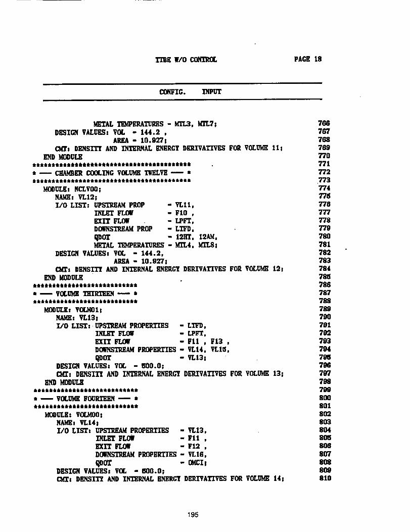
TI"BK WlOCI:)NI"P_L PAGE 18
CONFIG. INPUT
METAL TID_EP.ATURES - MTL3, MI'LTsDESIGN VALUEq: VIM., - 144.2 ,
AEEA - 10.927 !CMTs i)_iSZ_ AND INTERNAL ENERCY DEP.ZVATI"VESFOR VOLUMEIII
END _0DO'i_****************************************** _ CHAMBERCOOLING VOLI_K TWELVE--- ******************************************
MODULEs NCLVO0!NAME: VL19sl/O LIST: OPSTi_AM PROP - VL11,
INLET FLOW - FIO ,I_IT lq.OW - LPFT,DOWNSTREAMPROP - LTFD,qDOT - 19.HT, 12AM,METAL TEMPEILATURES- MI'L4, MTLS:
DESIGN VALUESt VOL - 144.2,AI_A - 10.927 s
CMI': DENSTTI AND INTEI_qAL IDII_C'T DEP.ZVATIVES FOR VOLUME19t
END KODULE**************************** ---- VOLUMETHIRTEEN --- *lk _ dktk'k tk_klkIktt'k dk_'k'k :kti't'k'k_kttkdk t •
MODI_Es VOL_lsNAMEs VL131I/O LXST: UPSTREAM PROPERZI2ES - LllB'D,
INLET FLOW - Lplrj[',EXIT FLOW " FII , IFI3 ,DOq_IST_AM PROPEILTZES- VL14, VL18,
qDOT - VLI3_DESIGN VALUES8 VOL - ISO0.OiCMI': OlllqSlTl AND IHTEIL_L ENERG"_/DEP.ZVATIVES FOR VOLUME 13s
END ),fODULKIkt IkdkIklk_lklk _tk ltktk 4k_kIklk dklkttktk _klk_
* ---.. VOLUMEFO_ --- *
MODULE: VOU_O INAMEs ll, I4 j]:/0 LISTs 1_S'1'9.E_ PROPERTIES - ti,13,
FLOW - Fll,EXXT FLOW - F12 ,
DOWNSTREAMPROPERTIES - VL16,
_ - a_cI sDESIGN VALUES: VOL - _00.0!CM_: DENSXT_ AND IN'/_RNAL ENERGY DERIVATIVES FOR VOLUME141
78876776878977077t
772
.77377477877877777877978O78178278378478n78678778878979O79171)27937947911796797
798799
8OO8018O28O38O481068O88O78O88O9810
195
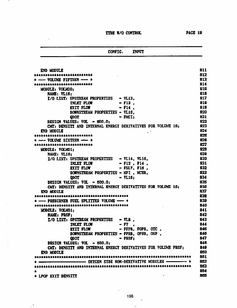
TTH W/O CONTROL PACE 19
i
C(_FIC. INPUT
END KODUT.JItttkkikiitkttitfrkfrkfkikkkikit
,---VOLU_ FI_ 1 •
MODULEs V_O;
I/O Ll_z __ PROPERTIES
EXIT lq.OW
- VL13,- F13 ," F14 ,
D__ PROPERTIES - VL16,
qDOT - I_CI;DE._XC_iVALU_t VOL - tSO0.O|CI_: DBNSZ'I_ AND INTERNAL ENERGY DERIVATIVES FOR VOLUME115;
END MOOU[_
* .-.---VOLU_ SIXTEI1N----- *66k_k6k6tJkkkkJk6ktt6kkk_k_kkkfr
KOOULll: VOLMOlsNAME: VLIG;Z/O LZSTz UPSTREAM PROPERTII_ - VLI4. VLIS,
INLI_r lq.Og -F12 . FI4 ,EXIT Lq.OW -FSLV, FltS.DOWNSTREAMPROPERTIES - MFI , _,
qDOT - VLI6!DESI_ VALUES: VOL - ISO0.O;c_r: DHNSXTY AND IN'J_RNAL ENERGY DERIVATIVES FOR VOLUME 16;
END MOOULK
* -- PI_BURNI_ FUEL SPLITTER VOLUME_'- *
XOOUI_: V(I_l;NAMEs PBSF;L"O LIST_ UPS'I_,U( PROPERTIES - 17.8 ,
£qLHT FLOW - F7 ,EXIT FLOW -FFPB, FOPB, OTC ,DOWNSTP.EAMPROPERTIES - FPRB, OPRB, OSF .qDOT - PBSFs
DESZCN VALUESt VCL - 500.OrCMZ: DENSIT_ AND INTERNAL ENERGY DERIVATIVES FOR VOLUME PBSF;
_D MOOULE**********************************************************************• OXYGENSIDE NON-DEILTVATIVEMODULES, ***********************************************************************
* LPOP I_IT DENSITY
81181281381481581681781881982089189.28"2389482S89682789889983O8318328338348"31183883783983984O841842843844841584884784884118808Cil
81538_48e_f
196
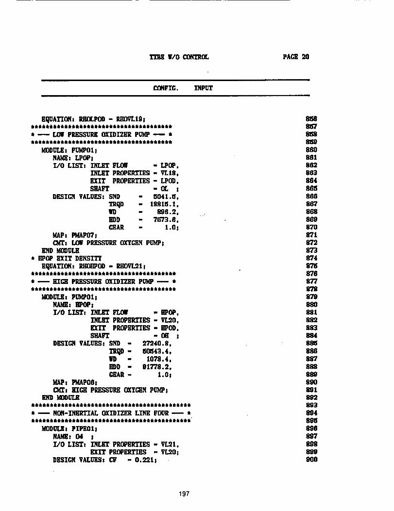
WO _OE, PAG_ 20
CONFTG. INPUT
EqUATIONs _OLPOD - _OVLIOs
• --- LOWPRESSURE OXIDIZER PUMP.---- •QIQtltIQillilllIQiltt_IQttIQQi_tt_
gOOULE: P_POI;NAME: LPOPII/0 LZST: INLET FLOW - LPOP,
INLET PROPERTIES - VL18,
EXIT PROPERTIES - LPOD,SHAFT - IX, I
DESIGN VALUES" SND - aO41.tJ,
- teexs.x,WD - 89G.2,IIDD - T_73.6,(:EAR - 1.0;
MAPs FMAP071CMT: LOWP_ESSORK OXYGENPUMP;
END gODULH* BPOP EXIT DENSITY
s_qUATTONs g_OHPOD - HOVL21s
* --'-- i[£GH PRBSSUP.B OXIDIZER PUMP -- *
MODI_.._: PUMPOlsNAMe: I;IPOPsIlO LISTs INLET' _LOW - HPOP,
INLET PP,OP_l_g - VL:20,EXI"T PP,DIP_P.TII_q - IIPOD,SHAFT - OH ;
DES'XCN VALUES;=_qD - 27940.8,T_D - _0_43.4,WD - 1078.4,BDD - 91778.2,GEAR - 1.0 s
MAPs PMAPOSsC_s HIGH P_ OXTr._N PUMPs
BND _OOULK
* .---- NON-13_TZAL OXZDIZ_ LINE _OUR .---. *
MODU[3s PXPHOI sNAMIE_ 04I/O LZST_ /?/LET PROPE'I_'XES - VL21,
BXXT PP.OPEILTXI_ - VL20;DESIGN VALUESs _ - 0.221s
8151]81578_8lmO86O861862863864868866867868869870871872873874875876877
87988088188988388488el88888788888989O89189280389489t58968978988999OO
197
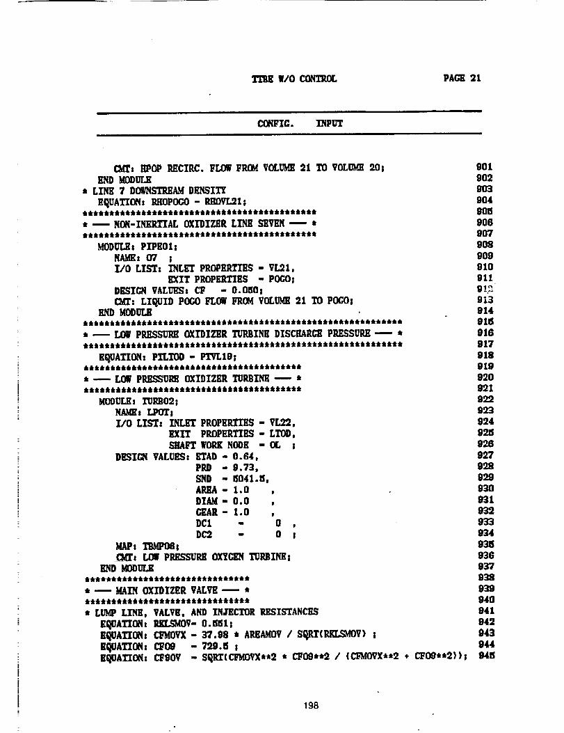
TFBE W/O CON_ PACK 21
i1| i n
CONFIC. INPUT
CMZs HPOP RECTP.C. FLOW FROMVOLUMII :21 TO VOLUME20; 901lIND MODULE 902
* LZI_ 7 DO.STeAM DEI_IT_ 903
EquATION: P..HOPOCO- P.IIOVL91; 904
* --- NON-INERTIAL OXIDIZER LINE SEVEN ---- * 906
MOOULE: PlPEOl; 908NAME: 07 ; 909l/O LIS'Tz INLET PROPEILTll_ - VL91, 910
EXZT PEOPHRTI_,q - POCO| 911DESZCN VALUES_ CI_ - O.O_iOs 91_
C_T: LII_UID POCO FLOW FROM VOLUME21 TO POCO! 813END MOOULK _ 914
* -- LOW PP,ESSUI_ OXIDIZER TUP,BINE DISCIIARCg PILEgSUP,/]---- * 91G
EquATION: PTLTOO - PTVLIg; 818***************************************** 819
• -- LOWPRI1EEUI_ OXZDIZI_ TURBINE -- • 920***************************************** 991
MoguLKs TURBO2; 922NAMEs LPOT; 993I/O LIST: INLET PROPERTIES - VLg9, 9:24
EXIT PROPERTIES - LTOO, 99._SHAFT WORKNOOK - OL ; 9:26
DESIGN VALUES: RTAD - O. 84, 927PPJ) - 9.73, 998SND " 1$041 • 5, 99.,9AREA- 1.0 , 93ODIAM- 0.0 , 931C_AR- 1.0 939DCl - 0 , 933DC:2 - 0 I 934
MAPs TI_IPOGs 935CM_'_ LOg P_SUP.B OXYCEN TURBZNE; 93G
END MOOULK 937******************************* 938* .--.- MAIN OXIDIZER VALVE -_" * 939******************************* 940
: LUMP LINE, VALVE, AND INJECTOR ILESISTANCKS 841
EQUATION: RKLSMOV- O.e_51z 949EQUATION: CI_MOVX- 37.98 * AREAMOV/ SqRT(RKLSMOV) ; 943K_ATIONz CF09 - 799.5 ; 944EQUATION: cFgov - SI_RZ(CFtdOVX**:2 * L"FOO**2 / (CFMOPX**:2 * CFOO**2)); 945
198
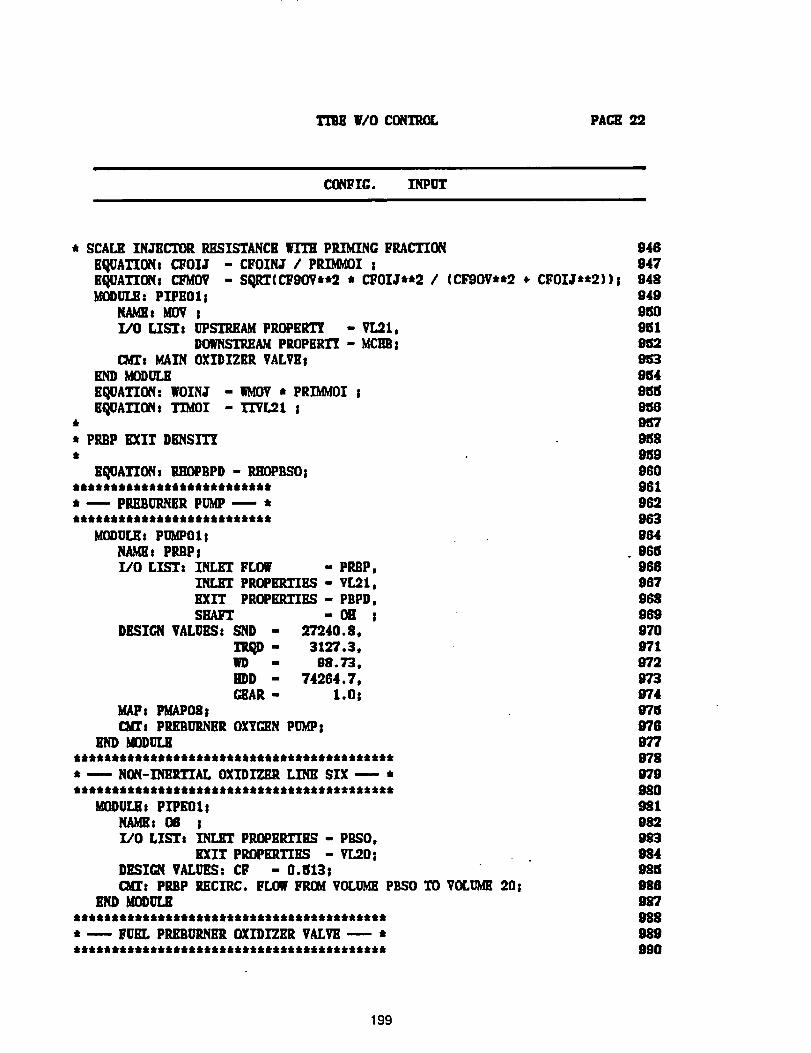
TrBBV/O CGNTROL PACE92
CO, FIG. INPUT
* SCALE INJECTOR RESISTANCE IrXTH PRIMING FRACTION
EqUATIONs CFOIJ - CFOIN_ / PP.XMMOIsEQUATIONs CFMOV - SO,_(CF9OYJ,*2 * CFOIJ**2 / (CI_OV**2 _. CFOIJ**2))IMODULE: PXPEOI j
NA_Ez MOV SL/O LISTs UPSTREAM PROPEi_T_ - VL21,
DOWNSTRHAMPROPERTI - MCHB!c_rt MAIN OXIDIZKR VALVKs
END MODULE
EQUATION: WOINJ - WMOV* PRIb_OI !
EQUATION: TIMOI -TEVL21 !i
* PREP EXIT DENSITI
EQUATION: 1RHOPBPD- RIlOPBSOt*************************** -- PEEBUP,NER PUMP ---. ***************************
MDDUUlt PUMPO1 !N_t_z PIUIP!X/O LIST: INLET FLOW " PREP,
INLET PROPERTIES " VL21,EXIT PROPEItTIES - PBPD,SHAFT - 011 I
DESIGN VALUES: SND - 27240.8,
TRqD - 3127.3,MD - 08.73,BD - 74064.7,(;_J_R - 1.0!
MAPs PM_P08CM_t PRKBURNEROXYC_N PUMPs
E_) MODULE
* -- NON-XNI_TIAL OXIDIZER LM SIX -- *
MODULEs PI'PE01:NAMEs 08 !l/O LZST_ IN'L£'T PROPKILTIES - PESO,
EXIT PROPERTIES - VL,','?.O:DESIGN VALUES: C9' - O.ISl3sCMIs PREP RECIRC. FLOWFROM VOLUMEPESO TO VOLUME20;
END MDOULR*****************************************• -.--- FUEL PR£BURNER OXIDIZER VALVE -- *
9469479489499tSO961
9539649t_lSO_(I95'791S89e_9060961969963964961S9669679639699700719729730749760789779789709809819899839849859869&'7088989990
199
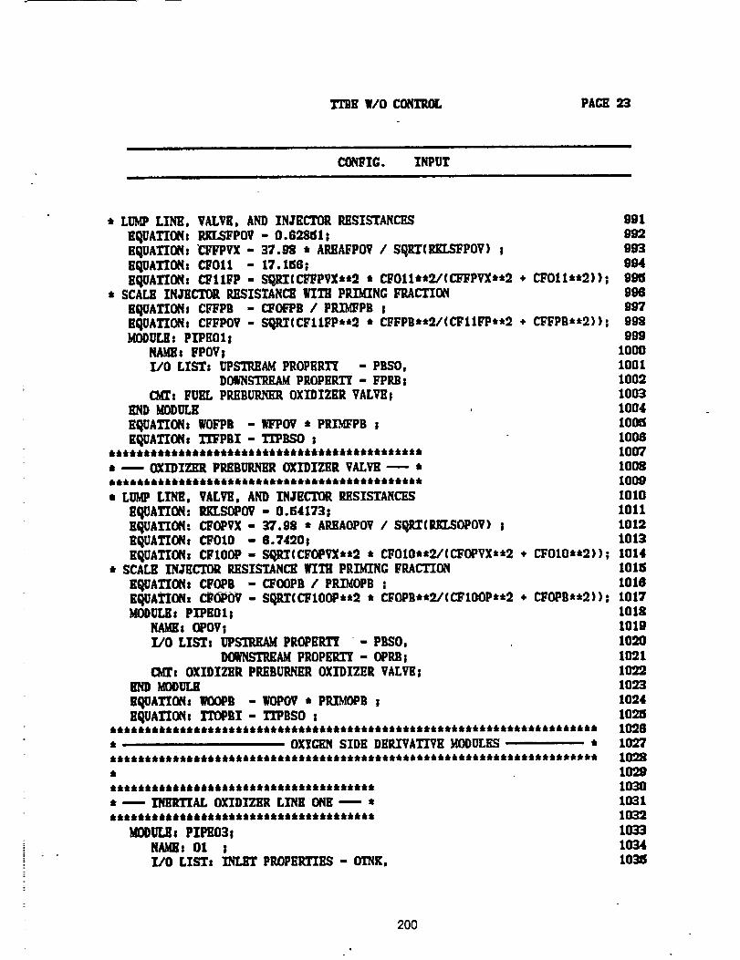
I'CBEW/O CONTROL PAGE 23
CONPlG. INPUT
* LUMP LINE, VALVE, AND INJECTOR RESISTANCES 091
EquATZO_Is P,KL_POV - 0.628_1! 992EQUATION: "ClqlPVX - 37.98 * AILEAFPOV/ SqlLT(ILEI.SFPOV) ! 993EquATION: CFOll - 17.156; 094EQUATION: C_IIFP - SOJLT(CI_PVX,to • CFOllt*9./(CI;FPVX**2 , CF011,,2))| 991_
, SCALE INJECTOR RESISTANCE WITH PRIMING FRACTION 996
EqUATIONs CI_PB - CF(A_B / PILI_PB ! 997EqUATIONs CFFPOV - SQRT(CFIIFP**O * CFFPB**'Y/(CIrI1FP**9 " CFFPB**2))S 998MODULE: PZPEOls 998
NAME: FPOVt 1000I/O LIST: UPSTREAM PROPERTY -PBSO, 1001
DOWNSTREAMPROPERTY - FPI_s 1002CMZs FUEL PP./]BUR/ql_ OXIDIZER VALVE! 1003
lIND MODULE 1004
EquATION: WOFPB - IG'POV • PRIMFPB ! 100_EquATION! TrFPBT - TI'PBSO s 1008
,••t****_*************************•****•****, 1007
* _ OXI'DIZER PREBURNHROXIDIZER VALVH_ * 1008
t LUMP LINE, VALVE, AND INJECTOR RESISTANCES 1010EQUATION. P.KLSOPOV- 0.94173| 1011EQUATION. CFOPVX - 37.98 • AEEAOPOV l SOJLT(EKLSOPOV) I 1012EQUATZONs CFOIO - 8.74901 1013EqUATIONs CFIOOP- SO.I_(CFOPVX**2 * CFOIO*"2/(CFOPVX**2 ÷ CF010"'2)); 1014
* SCALE INJECTOR ILESZSTANCI] WITH PRIMING FRACTION lOllS
EQUATIONs CFOPB - C_OOPB / PRX'MOPB; I010EQUATIONs C_OPOV - SD._T(C_IOOP**o * CFOPB**O/(CFIOOP**2 ÷ CFOPB**'))). 1017MODULE: PXPEOI ! 1018
NAMK_OPOV! 1019L,'O LIST: UPSTREAM PROPERT_ - PESO, 1090
DOWNSTREAMPROPERTY - OPP.Bs 1021CMT: OXIDIZER PREBUI_ER OXIDIZER VALVEs 1022
END MODULE 1023
EQUATION: WOOPB - WOPOV* PRXMOPB s 1024EQUATION: TT(_BX - TI_BSO s I09.JS
********************************************************************** 1028* OXTCHHSIDE DERIVATIVE gODULES * 1027********************************************************************** 1098• 1029************************************** 1030* ----- INERTIAL OXIDIZIIR LINE ONE _- * 1031************************************** 1039
MODULEs PXP£03! 1033NAMEs Ol ! 1034X/O LISTs INLET PP.OPBI_'ZILq- OT_. 103_
200
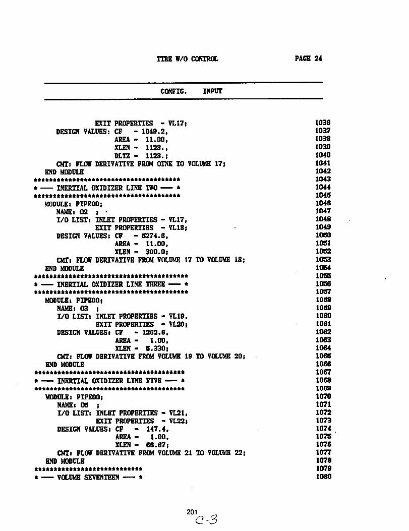
TI_E W/O CONT_ PAGE 24
CO_IG. INPUT
EXIT PROPERTIES - VL17|DESIG_ VALUES: CF - 1040.2,
AREA - 11.00,
XLEN - 1128.,DLTZ - 1128. s
c_r: FLOW DERIVATIVE FROM OTNICTO VOLUME17!END MODULE
* 1 INERTIAL OXIDIZER LINE TWO 1 *
_ee,_ee,eeei_e**i**e_leeeeee,eeeleeee_
MODULE: PIPKO0!NAMEs O_ II/0 LISTs INLET PROPERTIES - VL17,
EXIT PROPERTIES - VL18!DESIGN VALUES: CF - 8274.0,
AREA - 11.00,XLEN - 300.Or
CMT: _ DERIVATIVE FROMVOLUME17 TO VOLUME18;END MODULE
t -- INERTIAL OXIDIZER LINE THREE ---- *
MODULEs PZPEO0;NAME: 03 ;I/0 LISTt INLET PROPERTIES - VL10,
EXIT PROPERTIES - VL20;DHSIC_q VALUESs CF - 126"2.8,
AREA - I •00,XLEN - 8.330;
C_z FLOW DERIVATIVE FROM VOLUME19 TO VOLUME20;_D MODULE
* ---- INERTIAL OXIDIZER LINE FIVE ---- •
MODUL_ 2 PlPEOOs
NAMEs 05 S
I/O LISTs INLET PROPERTIES - VL21,
EXIT PROPERTII_ - VL22j
DESICR VALUES: CP - 147.4,
AREA " 1.00,X[JEN - 68.671
_s FLOW DERIVATIVE FROM VOLUME21 TO VOLUME22|END _ODULE
* -- VOLUMESEVENTEEN ---- t
1038103710381039104010411042104g1044I04M104610471048104910_01O151106210_31O154101_10_,810_57108S10_01060100110_21063106410_lOG8106"710681069107010711072107310'74IO'Ri10'701077107810'791080
201
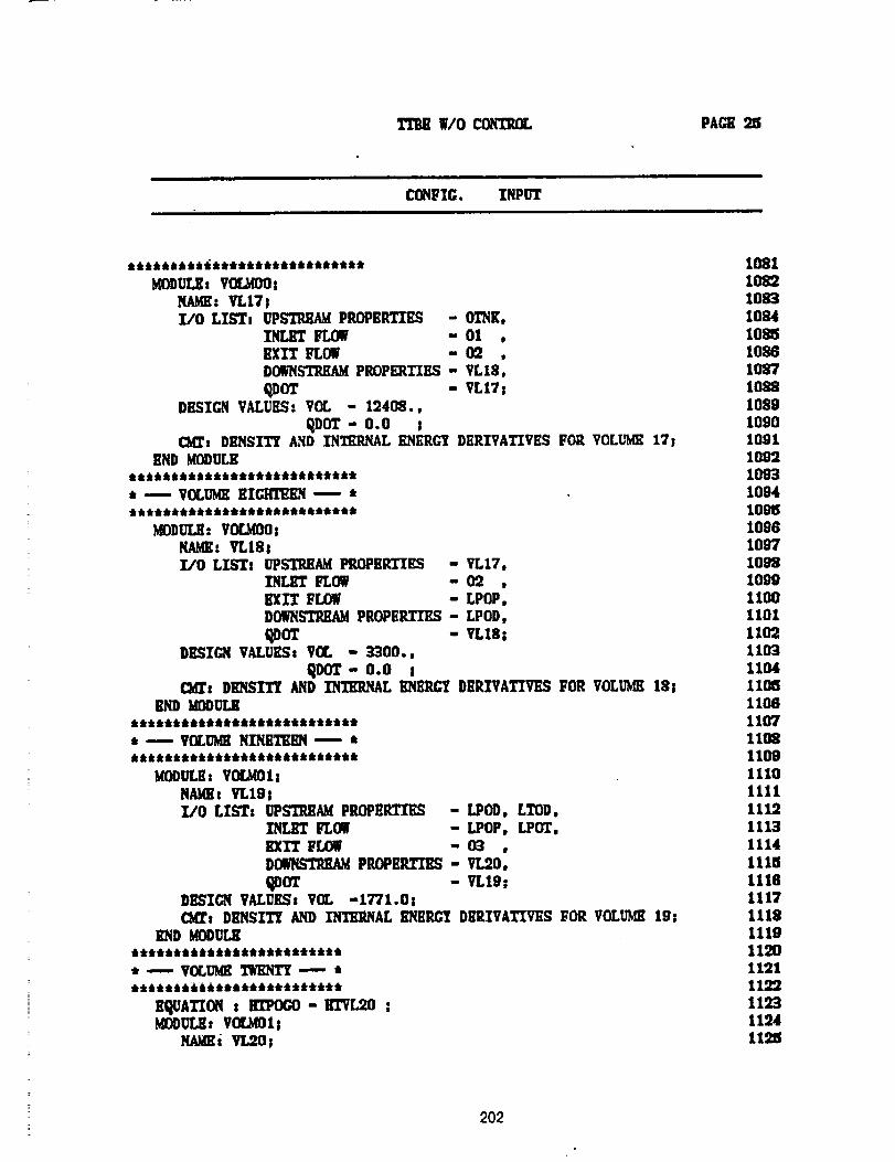
W/O COZFIT_ PAGE 25
CONFIG. INPUT
MODULEs V(IMO0;NAME: VLIT!I/0 LIST, UPg'/?.K_ PROPERTIES - OTNK,
INLET FLOW - Ol ,EXIT FLOW - 02DOWNSTRKAMPROPERTIES - VLI8,
QDOT - VL17!DESIGN VALUES: VOL - 12408.,
qOOT- 0.0 !C_: DBN$ITr AND INTEPJqAL I_ERG'7 DERIVATIVES F02 VOLUME17s
END MODULKk t:k 6 t4_ Jkkt k 4,k _kk_k:k:kt:kk kk_ttt
* ...---VOLUME EI_---- ****************************
I_ODUI_: VfX.MO0;N_: VLI8!I/O LIST# UPSTREAM PROPERTIES - VL17,
INLET FLOW - 02I_IT FLOW - LPOPoDO__ PROPERTIES - LPOD,
q_OT - VL18;DKSZC_qVALUES, VOL - 3300.,
qOOT- 0.0 ;c_r: DiI_"IT'f AND INTIIP.NAL I_ql_P.GYDERIVATIVE..q FOR VOLUME 18;
END gOOULK:k:k kkk:ktkk_k:kkkk& k:k k_t ktk kkt kt
* -- VOLUgl_ NINilTEIlN ---- *6 6 it6 jktttAi&ttttttta,_t a,t_t_i
UI)DULE: VOLqO1;NAMEr VLIOILtO LIST: UPSTREAM PROPERTIES - LPOD, LTOD,
INLET FLOW - LPOP, LPOT,EXIT FLOW - 03 ,DOWNSI'I_ PlU)PHRTIES - TL20,
qDOT - VLI9;DI_IC_q VALUES! VOL -1771.0!(Mrs DElqSITY AND INTH2NAL I_llRG'_ DERIVATIVES FOR VOLUgll 19!
108110821083108410851028108710821089109010911092109310941095109610971092long11001101110'2110311041105110B110711081109III01111111211131114
11151118111711121119112011211122112311241125
202
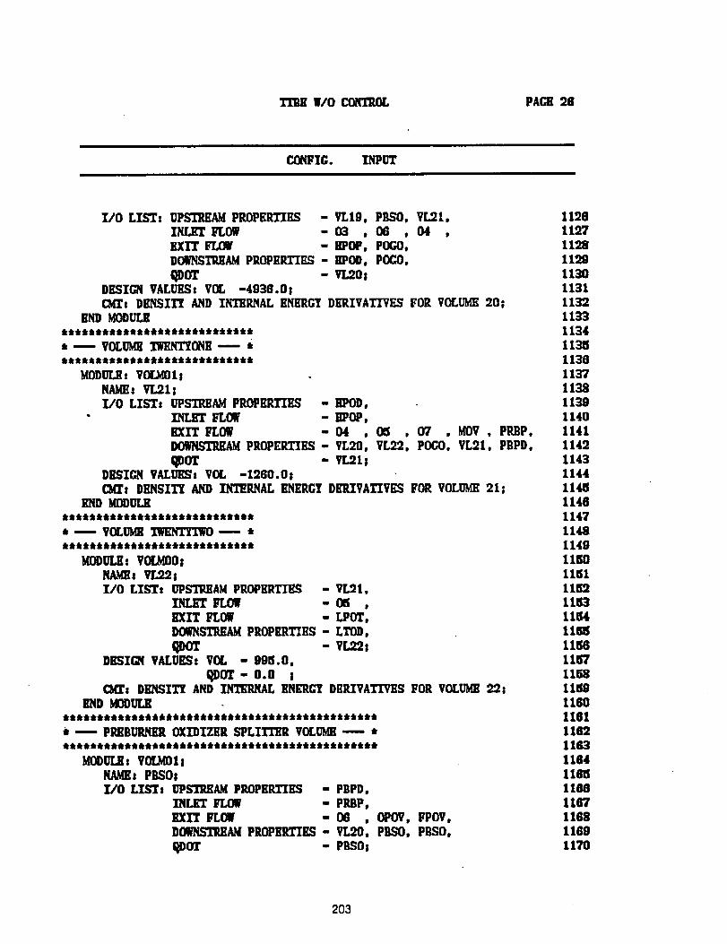
WO CONTROL PACH 28
CONFIC. INPUT
l/O LIST: UPSTI_AM PP.OPERTIIIS -VL19, PBSO, VLg.I,INLET FLOW - 03 , 06 , 04 ,eXIT FLOW - BPOP, POGO,DOWNSTREAMPROPIIILTII_ - POD, POCO,
ql)OT - VLg.0iDESZC_I VALUES: V(I. -4936.0;CM_t DKNSIT_ AND INTKRNAL KNRRCTDKI_VATIVKS FOR VOLUME20;
BND MODULEltti4,tta, ttttttttttttitttittt
*----VOLM MNT_ONE---
gODULKs VOL_OI tNAME: VL21:I/O LISTs UPSTRJ_AMPP.OPEP.TULq - llPOD,
" ZNLIIT FLOW - ilPOP,BXIT FLOW -04 , M . 07 . gOV , PI_P.DOWNSTH£AMPROPERTIES- VL20, VL92, POCO, VL21, PBPD,
qoor - v tsDBSICN VAM,_g: V0L -19G0.0iMs DIlNSITY AND INTERNAL ENERCI DERIVATI'VKS FOR VOLUME21;
lIND b_OOULRIItt tttt II tttt tt iilltttllt tt tlltt tt tlltt lit lit ttt t t t t
t----VOLM MNTYM _ tilt tli It tt ill tt lit tliilt II lit lit ill lit lit ill lltti tli ill 9 4 t t 4 t t t
MODULH: VOL_00;NA_s VL:?.q;UO LISTt UPSTI_AM PROPERTIES - VLql,
INLET I_LOW - 06 ,EXIT FLOW - [.POT,DO_STlillAg PROPERTIES - LTOD,ql)OT - VL92;
DBSI_I VALUES: VOL - 995.0,q OT - O.O t
Ms DHNSITT AND l_Ar. IlNKR_ DERIVATIVES FOR VOLUME_iEND MOOULg
ttlltt ill tttt ttttll tttttli tl tttt ill tt tl tlttt tit t t t t t t t t tit t t t _tttt itt
i -- PLIER OXIDIZER SPLITTlm VOLM -- *tttttt tit/ill tlltlltl ill lltlltllttill tt tt II ill II tttl t t t tit t t t t t t ttt t ttt tit
MI_ULll s VIX.ta) 1iNAMEs PBSOIT./O LT_"Tt UPSTRK_ PP.OPIlR.TIES - PBPD.
INLET FLOW - PRBP,EXIT FLOW - OG , OPOV, FPOV,DOWNS'TIUIAMPP_3P_lll"IllS- VL20, PgSO, PBSO.
qDOT - P6.._0;
11961197119.81199113011311132113'311341131S1136113711381139114011411142114311441148114611471148114911_01151
11ei3115411_115611571158115911601161116211631164116_1166116'7116811691170
203
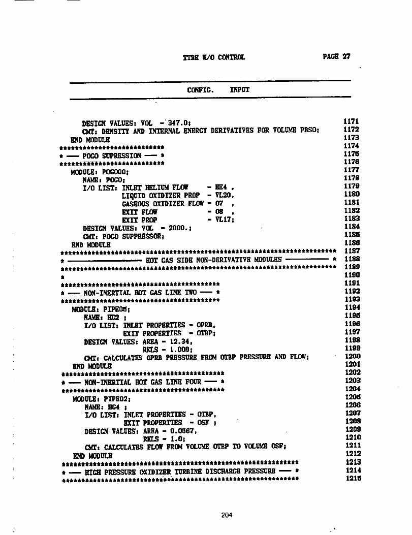
TTBE WO CONTROL PAGE 9?
CCNFIG. INPUTu
DESIGN VALUES: VOL -347.0s 1171C_: DENSITT AND INTER_L llh'ERGY DERIVATIVES FOR VOLUgE PBSOs 1172
END MODULE 1173t _t ttt t _kt t_t t_t_It a,_tk,i,,ik,I, 1174
t -- POCO SUPP.ESSION -- t 1175*********kkk**k*9*****gkkg* 1176
MODULE: POGO00s 1177NAMEs POCO! 1178LeO LIST: INLET HELIUM FLOW - m_4 , 1179
LIQUID OXIDIZER PROP - VLSO, 1180GASKOOS OXIDIZER lerOW - 07 , 1181EXIT FLOW - 08 , 1182EXIT PROP - VL17| 1183
DESIGN VALUES: VOL - 9000. I 1184CM_s POGO SUPPP.JL_OR! 1188
END MODULE 1186*********l,**************************t**,m************t****************** 1187* ........ BOT GAS SIDE NON-DERIVATIVE MODULES * 1188Idktta'&k 4'i&&i&&_k_k &a'a'i_llklllllttt_tltt�_t_ _tk_tlikk _k_k_k_b _kkk_ 1189
1190*************************************9*** 1191
***************************************** 1193hg3DULE: PIPEO5 _ 1194
NAME: EGg s 1198
LeO LISTs INLET PROPERTIES - OPRB, 1196EXIT PI_OP£P._TII_ - 01_P| 119'7
DESIGN VALUES: AREA - 12.34, 1198- 1.000| 1198
_: CALCULATES OPILBPP,IISS_ILE _ROM OT_P PP.ESSUI_ AND FLOW_ - 1200MODULE 1201
******************t*********************** 1202* 1 NON-INERTIAL EOT GAS LINE FOUR ---.- * 1203**********_,*_,*************J*************** 1204
MODULEs PIPE02 s 1205NAME: BG4 ! 1206LeO LIST: INLET PROPERTIES - OTBP, 1907
EXIT PP,OPElq_ES - O_P _ 1908DESIGN VALUES: AI_A - O.O_B7, 1909
ILELS- 1.0! 1210OMZ: CALCULAI"_ FLOW FROM VOLUM_ OTBP TO VOLUM_ OSF! 1211
END MODULE 1212
• -- HIGH PIU_gSURE OXIDIZER TURBINE DISCHARGE PRESSURE -- * 1214,i****_***_**,-_,_**_**-**_,_***_*******_**_*********_** 1215
2O,4
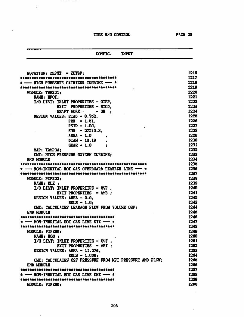
TrlmWlo_ PAGE 22
CONFIG. INPUT
EqUATIONs ZHPOT - ZOTBP:JNJNNtNttJJNJNNNNNNNJJNJN_NNNNJJNNNNNNNNt_
* -_- HIGH P_ OXIDIZER TURBINE ,--- *6_ 661_6_61N_NJ_NN 066tOONN61tikN_Ndk•6tQQQ_t_
MODULEs TURBO1 !NAMEs RPOT|]/0 LIS_, INLET PROPERTIES - 01_P,
EXIT PRDPERT]ES - IITOD,
SHAFT WORK • - OH S
DESIGN VALUESs ETAD - 0.7152,PRD " 1.51,P-_ID " 1.00,SND - 97240.8,AREA " 1.0DIAM - 10.19GEAR- 1.0 s
MAP, I_MPO_ sC_t RICH PRESSURE OXY_N TURBINEs
END MODULEJ JJJJJj_tJJJSJJ6jj6jJt_JJ_JJ_J6JJtJJJ6J_JJJJJJJJJ_JJJ
* ---- NON-_RTXAL HOT GAS OVERBOARD LEAKAGELINE -=-- t
MODULEs PIPEOgs
NAgE: OLK sX/O LISTs INLET PROPERTIES - OSF ,
BXIT PIK)PERTISS - _ SDEgTC_q VALUESt AREA - O. O,
- l.OsCM_s CALCULATES LEAKAGBFLOW FROMVOLUMEO_F!
END MODU[.K
• m NON-ZSEILTTALHOT GAS LZNB SIX _ •• •4_•_f_••frdr• fr••fk•6Jkfkt_k•a, dk••••••••• ••••_t•_
gODULEt PIPEOSsNAMEs BC6 sZ/O LIST: INLET PROPEILTZES- OSF .
KIlT PROPBRTZES - MFI sDRSTC_qVALU_Ss AI_A - 11.278,
_R_- l.O00sC_s CALCULATES OSF PEESSURI] FROMMFI PRESSURE AND FLOWs
BND MODUr,_
• --* NO_-XNS_ZZAL HOT GAS L]NB ONE --- *
MODULEs PZPEO_s
12181217121819101220122112oo192312241225122812.97
19981220123019.31123219331234123519.301937123819.38194012411942194312441245194812471248124g12_012at12iS212_1215412_512_12n'712_12rig1260
205
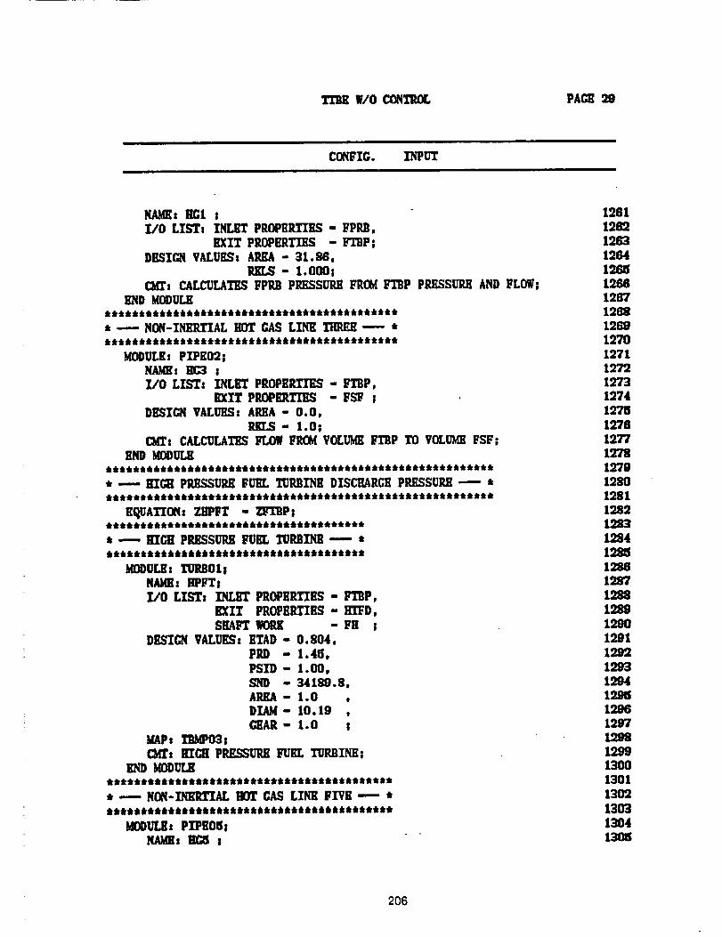
W/O CONTROL PAGE 29
Ct_IFIG. INPUT
N_s lIGt II/O LZS'T, INLET PROPEP..TIE._- FPP.B,
EXIT PROPI_qTIES - IVl'BP;DP_CTGNVALUR.% AlUM - 31._,
P,KLS- 1.000!CMT_ CALCULATES FPi_ PRESSURE FROM FI'BP PP.ESSU2H AND FLOW|
END MODULE
• ---- NON-INEP.TIAL HOT GAS LINK 1111_E ---- •
MODULE: PIPE02;NAME, IIC3 j]rJO LISTz ZNLilT PROPERTIES - FTBP,
EXIT PP.JOPKRTI'EN - FSF I
DESIGN VALUESg AI_A - O. O,P.KI.S- 1.0s
C_t CALCU_T_ FLOW _ VOLU_ FTBP TO VOLUMEFSF;
lIND KOI)UT.K
, --- RT_ PP,E_UP.E FURL TORI_I'NBDISCI_RCR PP._SUP.E -'-- •*********************************************************
K_A_CXq: ZB_P_ - _!**************************************
• -- KICII PRESSURE FUEL TURIIINB -- •**************************************
_U_: I'URB01!NAMEI EPFT!I/0 LISTs INLET PROPER'FIEN - F'L'2P,
EXZT IPRGPEP_EN - gLTD,SHAFT IK)IU{ - FH !
DESIGN VALUKS: I_T.AD- 0,804,PRD - 1.45,PSID- 1.00,8ND - 34189.8,AREA - 1.0DIAM- 10.19 ,GEAR- 1.0 !
MAPt I'�MPO':t;C_: I;TC_ PP.ESSUIUI FUEL TUP,BINBI
END _tODULB******************************************• _ NON-INEILtZXAL HOT (::AS LINK FI"VE ---- •******************************************
MODULE: PZPE05iNAME, !!_
12811269126312641265128812671265126919"701271127212731274127512781277127812791280128112821_312941285128812871288128919.98129112921293199419.981298129712981299130013011309130313641305
206
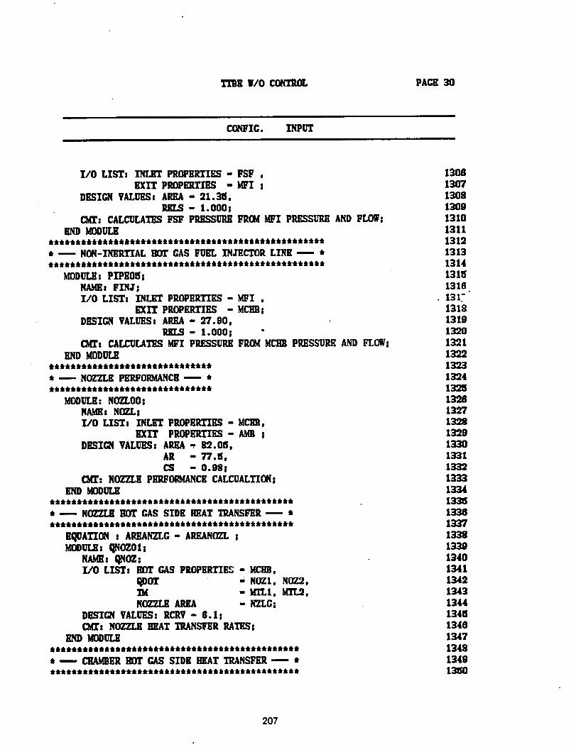
TTDE 11/0 CONTROL FAGK 30
CONFIG. INPUT
I/O LISTs INLET PROPERTIES - FSF ,
EXIT PI_PERTIES - MFI IDESIGN VALUESs AREA - 21.315,
- l.O00tCKI_: CALCULATES FSF P_P_ F_OM MFI PP.ESSUP.K AND FLOW;
END MODULEjttjjJj_jjtjjjJjjtttQjjJtJJJtJJJtttJJJJJJ_tJJSJJStJJt
tl -- NON-INERTTAL IK)T CIAS FUEL INJECTOR LINK -- tt***************************************************
MODULE: PlPE015iNAMEs FINJII/O LISTs INLET PROPERTIES -gllI ,
EXIT PROPILqTIES - MCHBIDESIGN VALUES: AREA - 97.90,
RKLS- l.O00I "c_rs CALCULATES MFI PRESSURE FRGq ML'HBPRESSURE AND FLOWI
END MODULEjiliijjiti_tJJJJJJitiliititJtJ
t ---- NOZ_ PERFORMANCE_ iiittllltitiitttttttttltttttitt
MODULE."NOZ_O0 INAIls NOZLIi/O LISTs INLET I_EII.TIES - MCgB,
EXIT PROIIInI.TXES " _ I
DESIGN VALUESi Ai_A -. 89.015,AR - T7.15,II_ - 0.081
C_: NOZZLE PKRFOI_MANCECALCUALTXONiEND MOOULE
6ttlt6tt6tt6t6ttttttlltttttAttttittittittt 6tt6
• -- NOZZLE HOT GAS SIDE HEAT TRANSI_R -- *tttttttttttttttttlltltl iltlttttllttlttttttt it
EQUATION i AHEANZLG- AP.,EANO2LIMODULEs _qOZ011
It qN_i[/0 LIST: IK_ GAS PROPKRT'_I_S- MCHE,
t_DOT ': NOZI, NOZ2,_M - XI"LI, MI"L2,NO_7_.LBAREA - NZLGI
DESIGN VALUES; RCRV - 6.1 ICKr: NOZZLE HEAT TRANSiqlR RATES!
END MODULENQiltttQQtQitiittt_Qtitk_iiiQt_Ni_lttttkttN_t
t -- Cl_k"ll HOT GAS SIDE HEAT TRANSFER- ***********************************************
130813071308130013101311131213131314131151318
.131."131813191320132113221323132413251328132713981329133013311332133313341335133813371338
134013411342134313441341513401343'134813481350
207
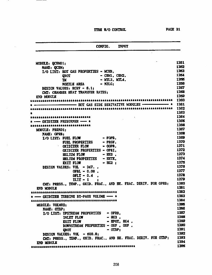
WO CONTROL PAGE 31
CONFXG. ]_PUT
MODULH: qCl:_ ls 13_ilNAME: 1_'3M; 13e;2l/O LISTs HOT GAS PROPi_ - MCHB, 13153
qDOT - CHMI, GEM2, 13e;41_ - MI"L3, M1T.4, 13_S
NOZZLE AIU_ - i_LG: 13_0DESIGN VALUES: lICllV- 6.1; 1357CMT: CIIA_ER I:mAT I'_I',L_ER RATES; 131_
END I_ODULB 13_9*********************************************************************** 1380* HOT GAS SIDE DERIVATIVE MODULES * 1361*********************************************************************** 1382, 1363****************************** 1384
* ---- OXIDIZER PP.EBUP..NEI_m , 1368****************************** 1388
MODULE: PBlll',,101; 136"/NAME: OPRB; 1388I/0 LIST: FUEL FLOW - FOPB. 1369
FUEL PROPERTXES - PBSF, 1370OXIDIZER FLOW - OOPB, 1371OXIDIZER PROPERTIES -OPBI, 1372Ig_Ll1_ FLOW - Im2 , 1373EILIUM PP,OPEI_TI_ - HFI_, 1374EXIT FLOW - EC9 : 1375
DESIGN VALUES: VCL - 347. , 1378OiqlL - 0.08 , 1377
OFLT- 0.4 , 1378ILIT- 1 ; 1379
041': P_S., TEMP., OXID. FllAC., AND m_. I;'RAC. DERIV. FOR OPP.II; 1380MODUr_ 1381
******************************************* 1382* --.-- OXIDIZER TURBINE BY-PASS VOLUME'---" * 1383******************************************* 1384
KODULB: V(X,M02s 138_NAM_: (H2P; 1386I/O LIST: UPSTREAM pROPERTIES - OPIUI, 1387
INLET FLOW - _ , 1388
EXIT FLOW - BPOT, EG4 , 1389D_AM PltOPE1L_ES- OSF , OS_ , 1390
I;_DOT - 0I"BP; 1391DESIGN VALUES: VOL - 500.0: 1399C2dX':PRESS., 11D,fP., OXID. FIIAC., AND lIE. FRAC. DEP._. FOR OTBP: 1393
END MODULE 1394**************************************************** 1368
208
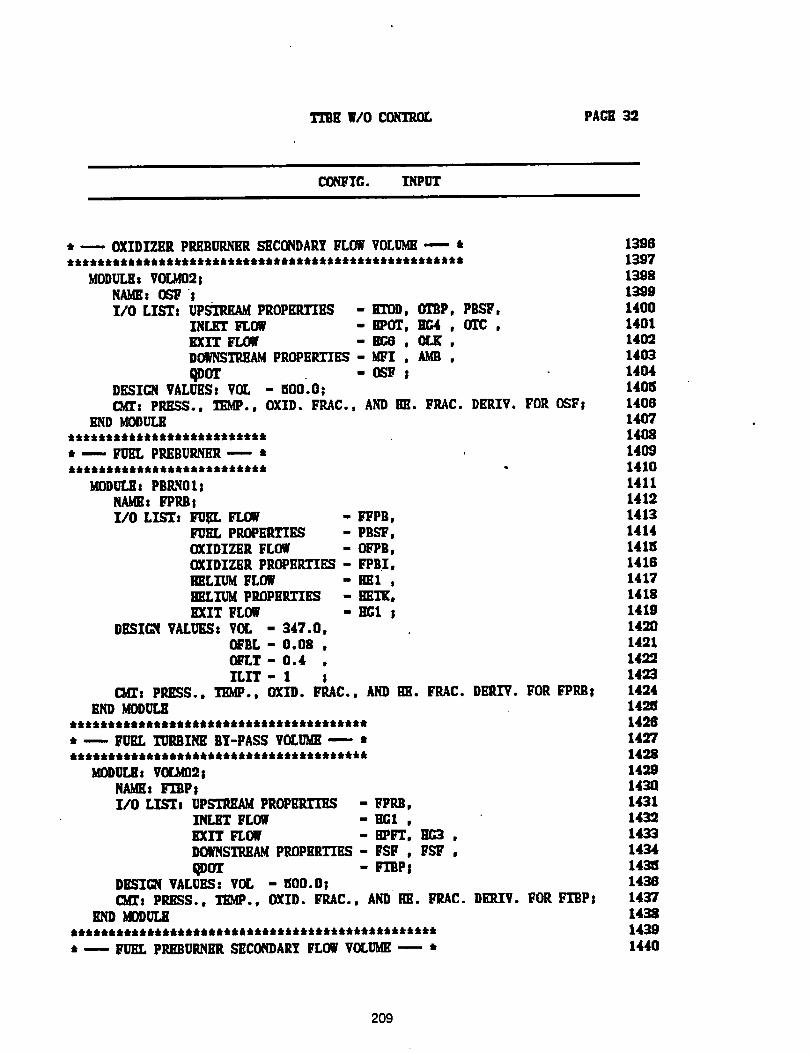
TIIlll W/O CON13tOL PACE 32
CONFIG. INPUT
* _-- OXIDIZER PREBUR_R S_CONDARY FLOW VOLU_ ---- *
MODULE: VOLM02;NAMH: _ sl/O LISTs UPSTREAM PROPERTIES - i_)0, OTBP, PlISF,
INLET FLOW -BPOT, _ , OTC ,EXIT FLOW - He8 , (IX ,D_/NSIPJ_4 PR_EP_-_ES - _I , k_ ,
DESIGN VALUES: VOL - _O0;0|
(1_: PRESS., TEMP., OXID. FI_C., AND ml. FI_C. DERIV. FOR OSFtEND KODUMI
tt/_tttt_ k k k/kttt_ktJkttt/ktktk
* ---- FUEL PI:tKBUi_llR--,- "t_, k/kt _k/k f_Ik/k &tlkttt_/k _,ttt_ _kdk •
_ODULE = PBI_O 1 =
NAME: FPP.B8I/O LIST, I_I_L FLOW - i_PB,
FUEL PROPERTH_ - PBSF,OXIDIZER FLOW " OFP9,OXIDIZER PROPEItl"IES - FPBI,HELIUM FLOW " HI1 ,HELIUM PROPBR.TIES - llET[,
EXIT FLOW - HGI sDESIGN VALUES: VOL - 347.0,
OFBL " 0.08 ,OFLT - 0.4 ,ILIT- I 1
(3_t PRESS., TIDQ., OXID. FI_C., AND HE. FI_C. DERIV. FOR FPI_8END _ODU[_
* ---- FUEL TURBINE BT-PASS VOLUM_ --- *
_OI)UL8: VO_I]2;N_4K: r_BP!Z/O LTSTt UPb'H_M( PROPBRTE_ - FPRB,
INLET FLOW " BGI ,EXIT FLOW -HPFT, _G3 ,DOWNSTREAMPltOP_I_TIES" FSF , FSF ,
qOOT - PTBPsDESZQ( VALUES: VOL - _00.0;C_t PRI_S., TEMP., OXID. FRAC., AND ml. FRAC. DI_.IV. FOR FIItP;
END MODUL_
* ---- _ PP,HBURNmt SECONDARYFLOWVOLUME-- ,t
139613971398139914001401140214031404140_140814071408140914101411141214131414141_14161417141814191421]14211492142314241425142614271428
14301431
1433
1434143_1438
1437143814391440
209
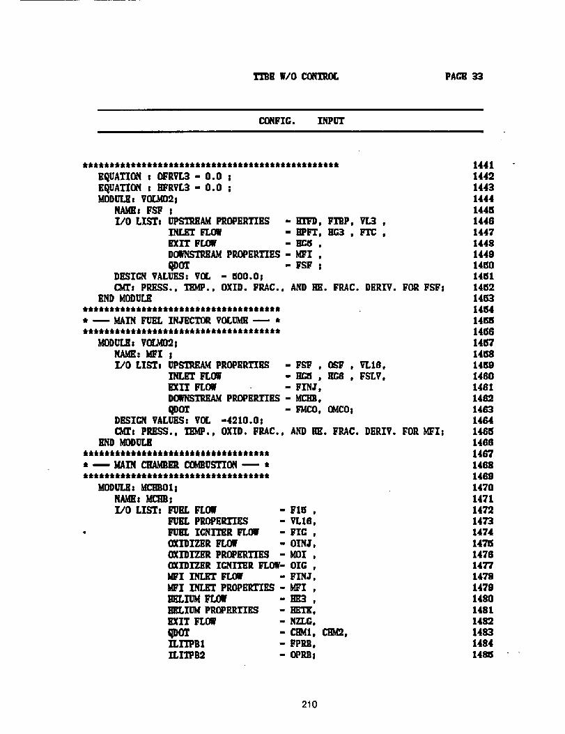
TTBE|/0 CONTIUX, PACE
CONFIG. INPUT
EQUATION I OPRVL3- 0.0 IEQUATION s I[FRVL3- 0.0 !MODUT._s VOL_2s
NAMEg FSF Il/O LISTg UPSTREAM PROPERTIES -B1TD, FTRP, VL3 ,
INLET FLOW - mqrI, _ , F'I'C,
EXIT FLOW - !!_ ,DO_L_REAM PROPERTIES - MFI ,
DESIGN VALUES: VOL - 500.0;CMTs PRESS., TEMP., OXID. FRAC., AND liE. FRAC. DERIV. FOR FSFI
END MODULE
. m MAIN FUEL INa-iICTOR VOLUM][_ **************************************
MODULEs VOLg02 !NAME: MFX II/0 LIb'_l UPS'?_AM PROPERTIES -FSF , O_ , VL18,
INLET FLOW - _ , HC,8 , FSLV,EXIT _ - FINJ',
DOWHS?IUD,W PIU)PERTIES - M.CHB,
qDOT - FWCO. OMCOsDESIGN VALUES! VOL -4210.0!CKrs PRESS., ZIIMP., OXID. FILAC., AND HE. FRAC. DERIV. FOR MFI!
END MODO[_************************************ _ MAIN CHAMBERCOMBUSTION-_' ************************************
UODULE: MCIIB01!
NAMlh MI_;I./0 LISTz FUEL FLOW
FUIIT., PROPERTIES• FUEL IGNZI'HR FLOW -
COCIDIT._ FLOWOXIDIZER PROPERTIES -OXIDIZER IGNITER FLOW-)EI INLI[T FLOI
WI INLET PROPER.TIES -HELIUM FLOW -HELIUM PROPERTIES -EXIT FLOW
qDOIXLFIPB1XLITPB2 -
FI5 ,VL16,FIG ,OINJ,MOI ,OIC ,FINJ,MFI ,m[3,
ling,NZLG,
CINI, CHM2,FPRB,OPIU]!
14411442144314441446144614471448144914_014_114_214eL_14_414_14_814157
145814K914601461148214831464146614601467146814691470
1471147214731474147_147614771478
147914801481
1482148314841485
210
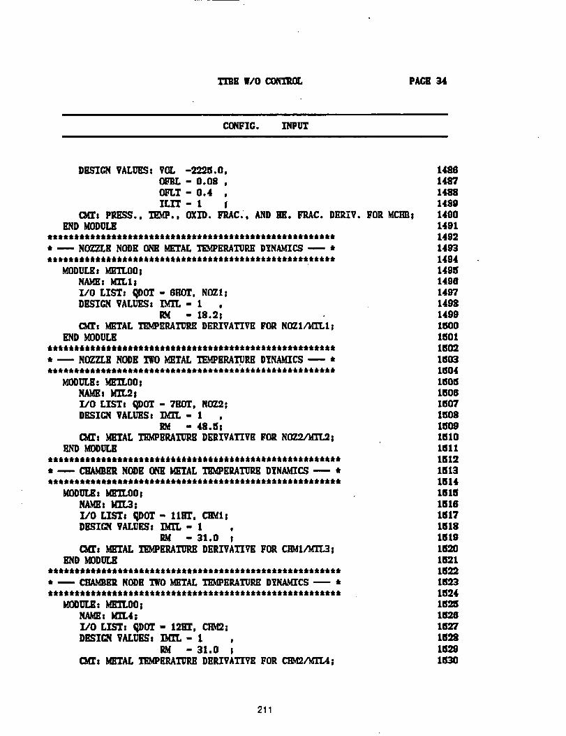
T_rBE 11/0 _ PAC_ 34
COh_IG. INPUT
DESIGN VALUES, VOL -2225.0,
OFBL - 0.08 ,Olq.T - 0.4 ,IT,IT- 1 I
(MUt PIU_S9., TEMP., OXID. Iq_AC., AND ira. FRAC. DERIV. FOR MCHIIsEND MODULE
***,,siisiisii,,***,**********i,,,,,******tili,,t****_* _ NOZZLE NODE ONE METAL TEMPERATUREDTNAMICS"--- *
MODULEt UEELOOlNA_: ]_QT..11Z/O LTS'T: ql)OT - 8HOT, NOZI|DESIGN VALUESs _- 1
IU4 - 18.2;(Mr: METAL T]_ERATUI_E DEP,IVATXTE FOR NOZ1,/MI%1!
l_qD MODULE******************************************************, u NOZZLE NODE TWOMETAL TEMPERATUREDYNA_4ZCS'--- *a._k_k_iktk*/k&_A***Atkti41411411*4kA _A _*AA _A_ k_ Ak**Ak_kA*kA _k _*_*
MODULE: _fl_lLOOsNAgEt gTL2j
Z/O LIST, QDOT - 71E)T, NGZ:21DESIGN VALUES: ZEIT,- 1
RM - 48.5_
CMT: _"L4L XE_PEP_,_'_RX DERIVATIVE FOR N__l_D _ODUI_
* --- CXA_ER NODE OflE METAL TEgPERATURE DTNA_CS --- *
_ODUL_ _ _ILO0NAME_ _L3..
T_O LIST_ QDOT- IIHT, C_1_DESIGN VALUES: IgTL- 1
IL_ - 31.0 ICMX: gETAL XI_,PEI_XUI_ DERIVATIVE FOR CI1MI_|
I_D MODULK
* -- CHAMBERNODE TWOMI_AL TE_PEP.ATUP.EDYNAMZCS-- *
M_)UL_: MIFL'LOOI
Z/O LZ_Et I_DOT- 121FF, CH_2|DESIGN VALUE.St IKIT.,- 1
EM - 31.0 I(ME: _"]L'AL XI_EP,_XURE DERIVATIVE FOR CE_/_I'L4!
14861487148814891490149114921493149414951498149714981499150015011502
15031504
1505150815o715o815o91510151115121513151415151518151715181519152015:21152215231524152515201527
15991530
211
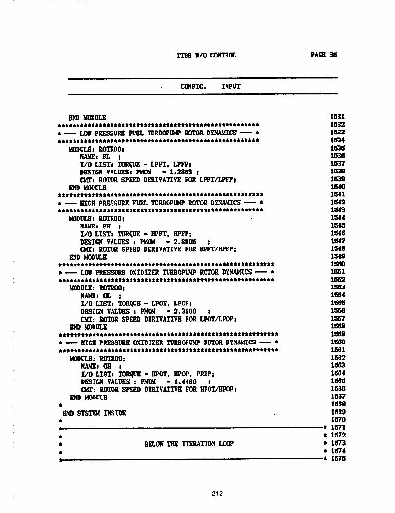
W/O COHTP.f_ PAGII 35
CONFIG. INPUT
END _ODULK
* -- LOWPRESSURE FUEL TUP31OPUgPIU3TORDYNAglCS _-" *
MODULE: 2OTTO:NAMEs FL ;I/O LIST: TORQUE- LPFT, LPFP!DIlSICN VALUilSs P_ - 1._953 I(Mrg ROTORSPIED DHI_VATIVII FOR LPYT/LPFPI
END MODULE*******************************************************, _ lllGll PP.I_SUP.E gUEL TUP._OPUgP ROTOR DYNAMICS _ ********************************************************
MODULE: RffTROO8NAME: Fll jI/0 LIST. TORQUE- llPFT, IIPFP|DESIGN VALUES s PgOg - 2.8505 sCM_s ROTORSPEIlD DERIVATIVE FOR IlPFT/HPFP=
gODULK
* -- LOW PP_SSURE OXIDIZER _IJRI_ ROTOR DYNAMICS -- ***********************************************************
MODU£,,_s _OTl_O !NAMe; IX. !
1/0 LISTs TOI_UK- LPOT, LPOP!D_SI_q VALUES : PgOg - 2.3900 !C_s ROTOR SPEED DKRIVATIVE _OR LPOT/LPOP:
END I_ODULK************************************************************ _ lrrGg PRRSSURR OXIDIZER TURBOPUMPROTOR DYNAMICS--.*
MOOULK, ROTP.O0NAMEs 011 Il/O LIgTa TOR.qUK- HPOT, llPOP, PP..BP_DESIGN VALUES : _ - 1.4496 tC_s ROTOR SPEED DEP.IVATIVII FOR IIPOTATPOP:
END MODITI.Kdr
END SY_ INSIDE
11
t
Ilk
BELOW TRZ ITERATION LOOP
1531153215331534153515361537153215391540154115491543154415451548
15471548154g1550155115_21553155415_m
1557155215591560
15611562
1564
1567156215691570
* 1571* 1572
,1573* 1574* 1575
212
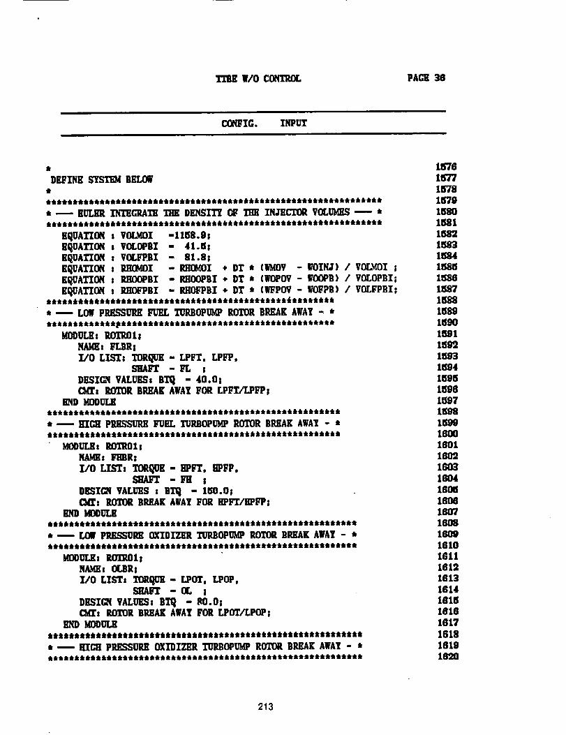
TI'BE W/O CONTROL PACE 36
CONFIG. INPUT
EQUATION : VOLMOI
EQUATION s VOLOPBI
EQUATION s VOLFPBI
EQUATION : _I
EQUATION : RII_X_BI
EQUATION s RIIIA_BI
-1158.9s- 41.5s- 81.8!- RIIOMOI + DT * (]G{OV - WOIMJ) / VOL_(OI !- P.HOOPBI * DT * (WOPOV- ¥OOPB) / VOLOPBZ;- P,HO_P6I ÷ DT * (_POV - WO_PB) / VOLFPBI:
******************************************************* ----LOW PIU_SSURK FUEL T_P.BOPUMPROTOR BleAK AWAT "- *******************************************************
MODUL_: P.OTRO1_NAME: FLBRs
I/O LIST: TORQUE- LPFT, LPFP,SHAFT - FL I
DESICR VALUESa BT_ - 40.01G,a_, ROTOR BREAK AWAYFOR LPFE/LPFP!
END MODIFL,K
* -- HIGH PRESSURE FUEL TURBOPUMP ROTOR BREAK AWA_ - *
MODULE, ROT201_NAME: L_IBR_I/O LIST# TORqU_ - BPFT, 8PFP,
SHAFT -i_ !
DESIGN VALUES : BTq - 150.0GKI_s ROTOR BREAK AWAY FOR BPFT/I]PFP:
END MODULE*********************************************************** -- LOW PP,IL.qSCREOXIDIZER T_DMP ROTOR BREAK AWAY - ***********************************************************
KOO_LE: _ETROI _NAME, OLBR!T/O LTb'_s I_EQI3E - LPOT, LPOP,
-II, IDESICR VALUES: BT_ - RO.OsC:MIt ROTOR BREAK AWAYFOR LPOT/LPOPl
END MODITI,,E************************************************************ ---- HIGH PRI_SSUREOXIDIZER TERBOP_'dPROTOR BREAK AWA? - ************************************************************
1576157715781579158015811582lm158415851588158715881589159o15911599159315941595150615971598159916001801
16031604160516061607160816091610181116121813
1614161518161817
1618181916"20
213
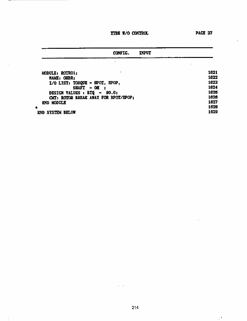
TTBR W/O C_k'q"Z'ROL PAGE _'7
CONFIG. INPUT
_ODULil: RO'l"itOls
NAME: Om_Ra
I/0 LIST: TOP,q_ - HPOT, HPOP,SHAFT - OH s
DESIGN VALUES : ill'q - 90.0s_: ROI"ORBREAK AWAYFOR IIPOT/HPOPs
END MODULE
lIND S_S;TEM BILLOW
1621
169.916'931624169518261627189.81699
214


