Embed Size (px)
Citation preview
AC Main spindle drives with regulated 2AD mainspindle motor
DOK-DIAX01-MAIN+2AD***-AUS1-EN-P
Selection guide
mannesmannRexroth
engineering
Indramat241629
2• DOK-DIAX01-MAIN+2AD***-AUS1-EN-E1,44 • 06.97
About this documentation
AC main spindle drives with regulated 2AD main spindle motor
Selection data
DOK-DIAX01-MAIN+2AD***-AUS1-EN-E1,44
• Mappe 7• HSPAD-AW.pdf• 9.567.013.4-04
This electronic document is based on the hardcopy document with documentdesig.: 9.567.013.4-04 EN / April 1994
The purpose of this document is
• to familiarize with the A.C. main spindle drive system,
• to define available power ratings,
• to demonstrate the use of standard and optional functions in machine toolapplications, and,
• to select a main spindle drive.
This document makes it easy to
• record the performance-related details of the main spindle drive,
• work out and record the necessary motor and drive options, and,
• make rapid and effective contact with our Sales Department.
This symbol serves to remind you that an entry has to be made in the "selectionlist". It corresponds to the word "option" in bold in the respective paragraphto the right or in the adjacent diagram.
Titel
Type of documentation:
Documenttype
Internal file reference
Reference
This documentationis used:
© INDRAMAT GmbH, 1994Copying of this document, and giving it to others and the use or communicationof the contents thereof, are forbidden without express authority. Offenders areliable to the payment of damages.All rights are reserved in the event of the grant of a patent or the registrationof a utility model or design. (DIN 34-1)
The electronic documentation (E-doc) may be copied as often as needed ifsuch are to be used by the consumer for the purpose intended.
All rights reserved with respect to the content of this documentation and theavailability of the products.
INDRAMAT GmbH • Bgm.-Dr.-Nebel-Straße 2 • D-97816 LohrTelefon 0 93 52 / 40-0 • Tx 689421 • Fax 0 93 52 / 40-48 85
Dept ENA (MR, FS)
Copyright
Validity
Publisher
Designation of documentation Release- Comentsup to present edition date
9.567.013.4-04 EN/05.94 Apr./94 P-Dok Edition
DOK-DIAX01-MAIN+2AD***-AUS1-EN-E1,44 Jun./97 First E-Dok
Change procedures
3• DOK-DIAX01-MAIN+2AD***-AUS1-EN-E1,44 • 06.97
Angebot erstellenAngebot anfordern
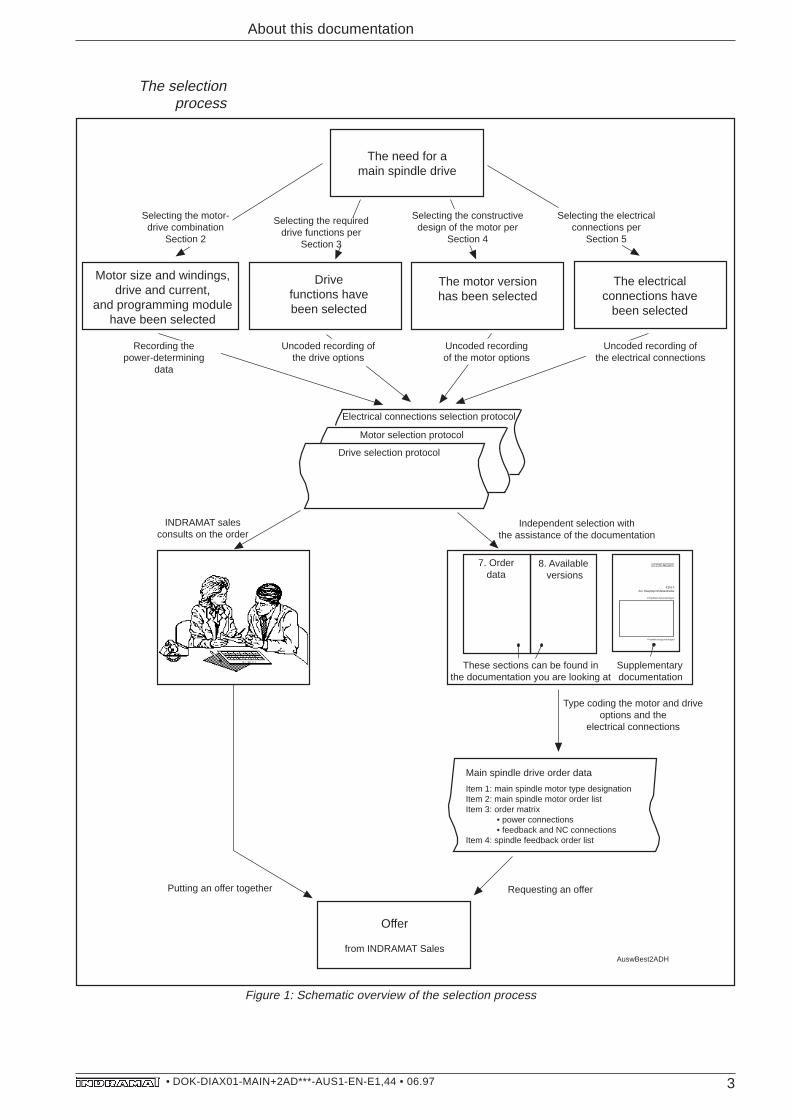
The selectionprocess
About this documentation
Electrical connections selection protocol
KDA 3AC-Hauptspinndelantriebe
Projektierungsunterlagen
Projektierungsunterlagen
The need for a main spindle drive
Selecting the requireddrive functions per
Section 3
Motor size and windings,drive and current,
and programming modulehave been selected
Drivefunctions havebeen selected
The motor versionhas been selected
Uncoded recording ofthe drive options
Drive selection protocol
Motor selection protocol
INDRAMAT salesconsults on the order
Independent selection withthe assistance of the documentation
Supplementarydocumentation
Type coding the motor and driveoptions and the
electrical connections
Putting an offer together
Offer
from INDRAMAT Sales
Requesting an offer
AuswBest2ADH
The electrical connections have
been selected
Selecting the constructivedesign of the motor per
Section 4
Selecting the electricalconnections per
Section 5
Main spindle drive order data
Item 1: main spindle motor type designationItem 2: main spindle motor order listItem 3: order matrix • power connections • feedback and NC connectionsItem 4: spindle feedback order list
Selecting the motor-drive combination
Section 2
Uncoded recordingof the motor options
Uncoded recording ofthe electrical connections
Recording thepower-determining
data
7. Orderdata
8. Available versions
These sections can be found inthe documentation you are looking at
Figure 1: Schematic overview of the selection process
Requesting an offerPutting an offer togetherGuidelines on the selecting process
4• DOK-DIAX01-MAIN+2AD***-AUS1-EN-E1,44 • 06.97
Table of Contents
Table of Contents
1. Introduction to the A.C. main spindle drive system 6
1.1. Speed characteristics .......................................................................6
1.2. Modular main spindle drives ............................................................7
1.3. Main spindle drives for direct mains connection ................................8
2.2. Selection lists ...................................................................................9
2. Power ratings 9
2.1. Nominal power ratings .....................................................................9
2.2 selection list .................................................................................... 11
2.3. Performance curves .......................................................................12
3. Functions and features of main spindle drives 33
3.1. Functions allocated to operating mode ..........................................333.1.1. Changing the operating mode during operation ............................343.1.2. Functions for main spindle drive mode ..........................................343.1.3. Functions for C-axis mode .............................................................383.1.4. Functions for master/slave mode ...................................................40
3.2. Functions independent of the operating mode ..............................413.2.1. Speed command ............................................................................413.2.2. Direct mains connection (for RAC) ................................................413.2.3. Emergency-stop (E-stop) / mains off function ................................413.2.4. Two-motor changeover ..................................................................433.2.5. AS programming module ...............................................................43
3.3. Messages / Signals ........................................................................44
3.4. Control unit cooling ........................................................................463.4.1. Modular main spindle drives ..........................................................463.4.2. Main spindle drives for direct connection to the mains (RAC) .......47
3.5. Mechanical accessories .................................................................48
4. 2AD main spindle motor options 49
4.1. Mounting ........................................................................................49
4.2. Power connection...........................................................................49
4.3. Cooling methods ............................................................................49
4.4. Holding brake .................................................................................49
4.5. Output shaft ....................................................................................49
4.6. Shaft sealing ring ...........................................................................49
5• DOK-DIAX01-MAIN+2AD***-AUS1-EN-E1,44 • 06.97
Table of Contents
4.7. Non-drive shaft end ........................................................................50
4.8. Shaft bearings ................................................................................50
4.9. Vibration severity grade .................................................................50
5. Electrical connections 51
6. Selection records 53
7. Ordering details 56
7.1. Main spindle motor .........................................................................57
7.2. Main spindle drive ..........................................................................577.2.1. Main spindle drive TDA 1.3 ............................................................577.2.3. Main spindle drive RAC 2.3 ...........................................................587.2.2. Main spindle drive KDA 3.3 ............................................................587.2.4. Main spindle drive RAC 3.5 ...........................................................597.2.5. Main spindle drive RAC 4.3 ...........................................................59
7.3. Electrical connections ....................................................................60
7.4. Spindle feedback............................................................................62
8. Available versions 63
8.1. Modular main spindle drive TDA 1 .................................................63
8.2. Modular main spindle drive KDA 3 .................................................64
8.3. Main spindle drive RAC 3 ..............................................................65
8.4. Main spindle drive RAC 2 ..............................................................66
8.5. Main spindle drive RAC 4 ..............................................................67
8.6. Main spindle motor 2AD100 ...........................................................68
8.7. Main spindle motor 2AD101 ...........................................................69
8.8. Main spindle motor 2AD132 ...........................................................70
8.9. Main spindle motor 2AD160 ...........................................................71
8.10. Main spindle motor 2AD180 ...........................................................72
8.11. Main spindle motor 2AD200 ...........................................................73
8.12. Main spindle motor 2AD225 ...........................................................74
8.13. Programming module AS ...............................................................75
9. Index 76
10. Summary of additional documentation 80
6• DOK-DIAX01-MAIN+2AD***-AUS1-EN-E1,44 • 06.97
Depending upon the power requirements, a technical distinction is madebetween the two versions of the A.C. main spindle drive system:
• modular main spindle drives up to 22 kW rated output for bus connectionand incorporation in a drive package with common power supply unit, or,
• main spindle drives up to 93 kW rated output for direct connection to themains.
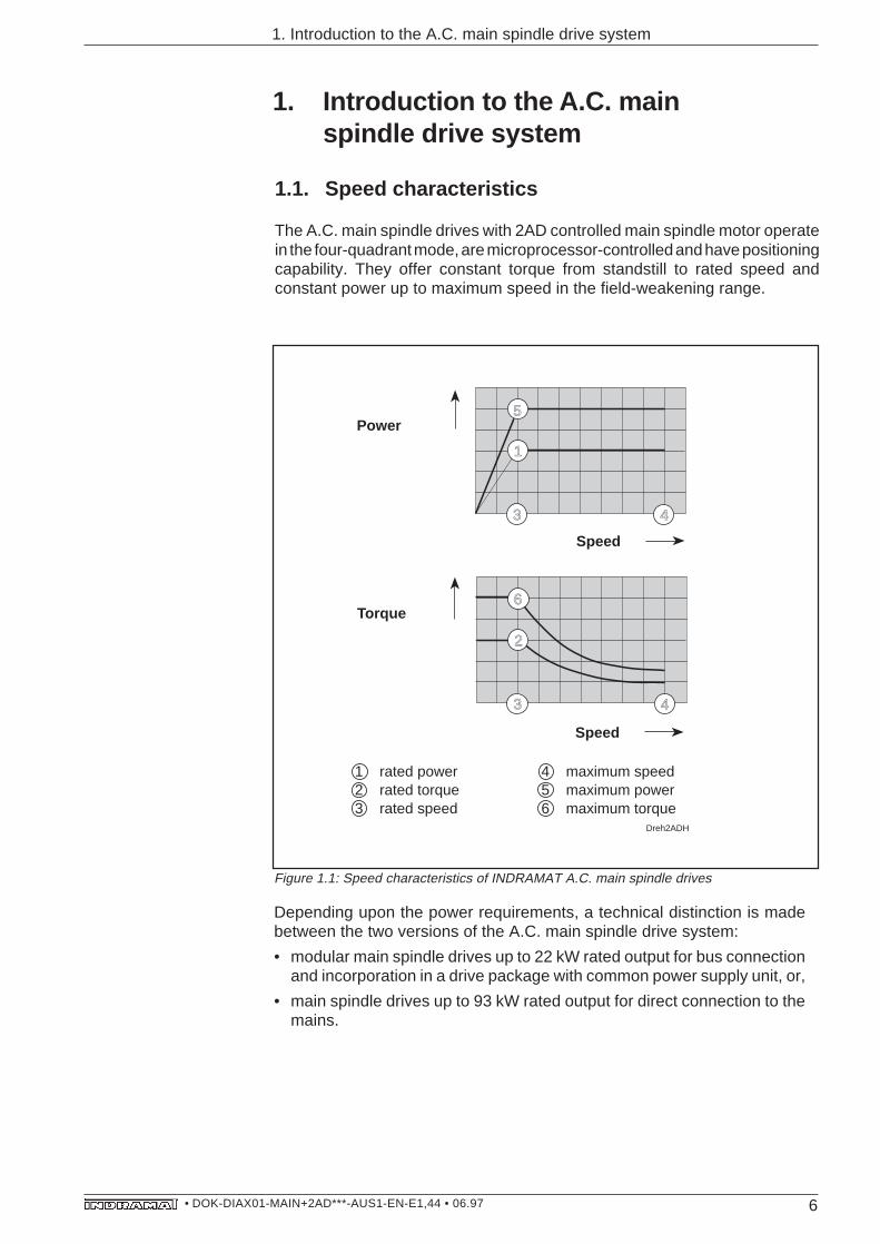
Figure 1.1: Speed characteristics of INDRAMAT A.C. main spindle drives
Speed
Power
Torque
Dreh2ADH
5
1
3 4
3 4
6
2
Speed
1 rated power2 rated torque3 rated speed
4 maximum speed5 maximum power6 maximum torque
1. Introduction to the A.C. main spindle drive system
1. Introduction to the A.C. mainspindle drive system
1.1. Speed characteristics
The A.C. main spindle drives with 2AD controlled main spindle motor operatein the four-quadrant mode, are microprocessor-controlled and have positioningcapability. They offer constant torque from standstill to rated speed andconstant power up to maximum speed in the field-weakening range.
7• DOK-DIAX01-MAIN+2AD***-AUS1-EN-E1,44 • 06.97
Versorgungseinheitmodulares Hauptspin-delregelgerät TDA
1.2. Modular main spindle drives
mod2ADH
Mains
Power supply unit modular main spindle drive
TDAorKDA
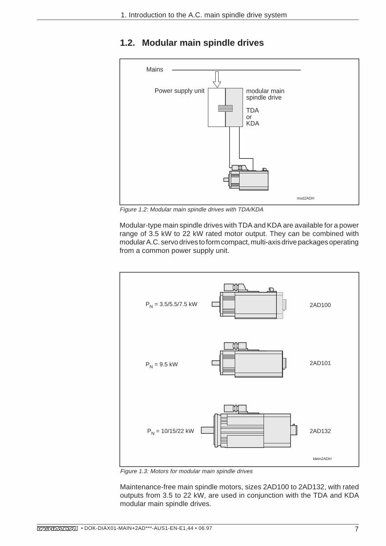
Modular-type main spindle drives with TDA and KDA are available for a powerrange of 3.5 kW to 22 kW rated motor output. They can be combined withmodular A.C. servo drives to form compact, multi-axis drive packages operatingfrom a common power supply unit.
Figure 1.3: Motors for modular main spindle drives
Maintenance-free main spindle motors, sizes 2AD100 to 2AD132, with ratedoutputs from 3.5 to 22 kW, are used in conjunction with the TDA and KDAmodular main spindle drives.
1. Introduction to the A.C. main spindle drive system
klein2ADH
2AD100PN = 3.5/5.5/7.5 kW
2AD101
2AD132
PN = 9.5 kW
PN = 10/15/22 kW
Figure 1.2: Modular main spindle drives with TDA/KDA
8• DOK-DIAX01-MAIN+2AD***-AUS1-EN-E1,44 • 06.97
1. Introduction to the a.c. main spindle drive system
1.3. Main spindle drives for direct mains connection
Mains
Main spindle driveRAC 3orRAC 2orRAC 4
RAC2ADH
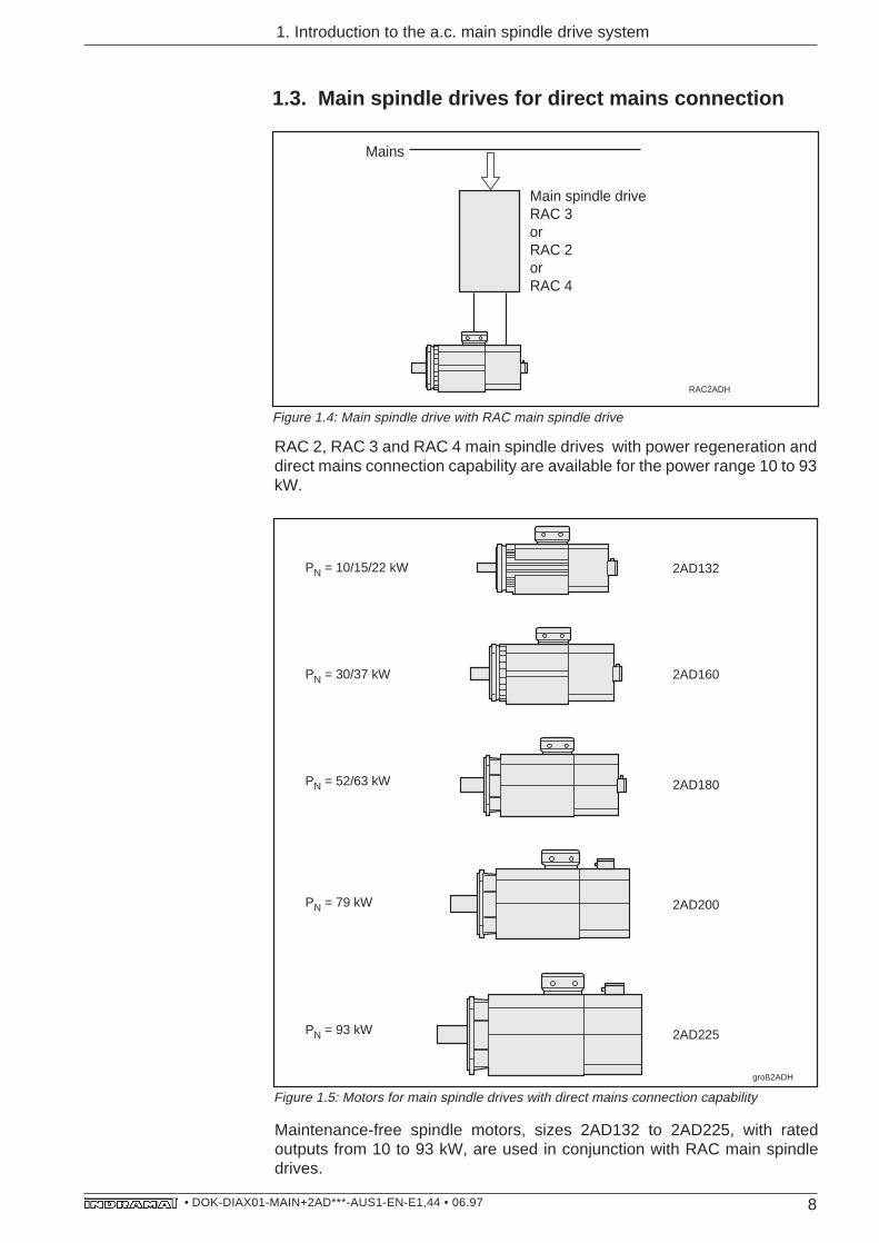
Figure 1.4: Main spindle drive with RAC main spindle drive
RAC 2, RAC 3 and RAC 4 main spindle drives with power regeneration anddirect mains connection capability are available for the power range 10 to 93kW.
groß2ADH
2AD132
2AD160
2AD225
2AD180
2AD200
PN = 10/15/22 kW
PN = 30/37 kW
PN = 52/63 kW
PN = 79 kW
PN = 93 kW
Figure 1.5: Motors for main spindle drives with direct mains connection capability
Maintenance-free spindle motors, sizes 2AD132 to 2AD225, with ratedoutputs from 10 to 93 kW, are used in conjunction with RAC main spindledrives.
9• DOK-DIAX01-MAIN+2AD***-AUS1-EN-E1,44 • 06.97
2. Power ratings
2. Power ratings
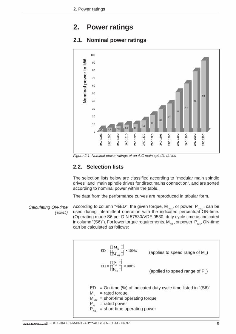
2.1. Nominal power ratings
Figure 2.1: Nominal power ratings of an A.C main spindle drives
2.2. Selection lists
The selection lists below are classified according to "modular main spindledrives" and "main spindle drives for direct mains connection", and are sortedaccording to nominal power within the table.
The data from the performance curves are reproduced in tabular form.
According to column "%ED", the given torque, Mmax
, or power, Pmax
, can beused during intermittent operation with the indicated percentual ON-time.(Operating mode S6 per DIN 57530/VDE 0530, duty cycle time as indicatedin column "(S6)"). For lower torque requirements, M
KB , or power, P
KB , ON-time
can be calculated as follows:
ED
ED
= ×
= ×
M
M
P
P
N
KB
N
KB
2
2
100
100
%
%
ED = On-time (%) of indicated duty cycle time listed in "(S6)"MN = rated torqueMKB = short-time operating torquePN = rated powerPKB = short-time operating power
(applies to speed range of MN)
(applied to speed range of PN)
Calculating ON-time(%ED)
2AD
100
B
2AD
100
C
2AD
100
D
2AD
101
D
2AD
132
B
2AD
132
C
2AD
132
D
2AD
160
B
2AD
160
C
2AD
180
C
2AD
180
D
2AD
200
C
2AD
225
C
3,5 5,5 7,5 9,5 1015
2230
37
52
63
79
93
0
10
20
30
40
50
60
70
80
90
100
2AD
100
B
2AD
100
C
2AD
100
D
2AD
101
D
2AD
132
B
2AD
132
C
2AD
132
D
2AD
160
B
2AD
160
C
2AD
180
C
2AD
180
D
2AD
200
C
2AD
225
C
Nen
nle
istu
ng
in
kW
Nom
inal
pow
er in
kW
10• DOK-DIAX01-MAIN+2AD***-AUS1-EN-E1,44 • 06.97
2. Power ratings
Mod
ular
mai
n sp
indl
e dr
ives
(3.
5 kW
... 2
2 kW
)
Con
tinuo
us d
uty
(S1)
Sho
rt tim
e du
tyM
axim
um d
ata
3)M
ain
spin
dle
Mai
n sp
indl
eP
rogr
amm
ing-
(S2)
1) 2
)(S
6)m
otor
driv
em
odul
e
Rat
edR
ated
Rat
edM
axim
umP
ower
Torq
ueE
DTo
rque
ED
pow
erto
rque
spee
dsp
eed
PN
MN
n Nn m
axP
KB
MK
BM
max
kWN
mm
in-1
min
-1kW
Nm
%N
m%
3.5
22.0
1500
9000
532
.049
50.0
152A
D10
0B-B
• • •
• • -
AS
• 3…
TDA
1.3
-050
-3…
AS
17 •
/005
-000
5.5
35.0
1500
9000
8.3
53.0
4410
5,0
112A
D10
0C-B
• • •
• • -
AS
• 3…
TDA
1.3
-100
-3…
AS
17 •
/006
-000
7.5
48.0
1500
9000
11.3
72.0
4410
5.0
212A
D10
0D-B
• • •
• • -
AS
• 3…
TDA
1.3
-100
-3…
AS
17 •
/007
-000
7.5
48.0
1500
9000
11.3
72.0
4410
5.,0
212A
D10
0D-B
• • •
• • -
AS
• 3…
KD
A 3
.3-1
00-3
…A
S13
• /0
07-0
00
9.5
60.0
1500
9000
1489
.044
108
312A
D10
1D-B
• • •
• • -
BD
• 3…
TDA
1.3
-100
-3…
AS
17 •
/024
-000
9.5
60.0
1500
9000
1489
.044
108,
031
2AD
101D
-B •
• • •
• -B
D •
3…K
DA
3.3
-100
-3…
AS
13 •
/024
-000
1064
.015
0075
0015
96.0
4496
,044
2AD
132B
-B •
• • •
• -B
S •
3…K
DA
3.3
-100
-3…
AS
13 •
/009
-000
1064
.015
0075
0015
96.0
4416
5,0
152A
D13
2B-B
• • •
• • -
BS
• 3…
KD
A 3
.3-1
50-3
…A
S13
• /0
19-0
00
1596
.015
0075
0022
.514
3.0
4414
3,0
442A
D13
2C-B
• • •
• • -
BS
• 3…
KD
A 3
.3-1
50-3
…A
S13
• /0
10-0
00
2214
0.0
1500
7500
2415
3.0
8417
6,0
632A
D13
2D-B
• • •
• • -
BD
• 3…
KD
A 3
.3-1
50-3
…A
S13
• /0
12-0
00
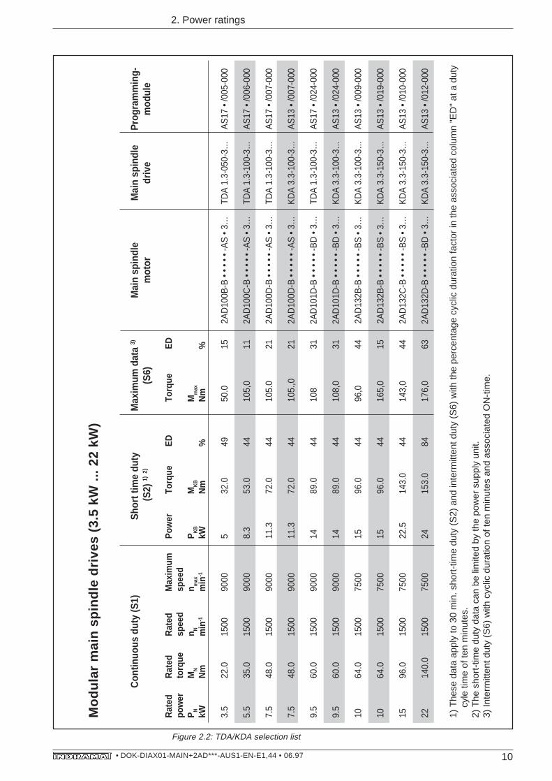
1) T
hese
dat
a ap
ply
to 3
0 m
in. s
hort
-tim
e du
ty (
S2)
and
inte
rmitt
ent d
uty
(S6)
with
the
perc
enta
ge c
yclic
dur
atio
n fa
ctor
in th
e as
soci
ated
col
umn
"ED
" at
a d
uty
c
yle
time
of te
n m
inut
es.
2) T
he s
hort
-tim
e du
ty d
ata
can
be li
mite
d by
the
pow
er s
uppl
y un
it.3)
Inte
rmitt
ent d
uty
(S6)
with
cyc
lic d
urat
ion
of te
n m
inut
es a
nd a
ssoc
iate
d O
N-t
ime.
Figure 2.2: TDA/KDA selection list
TDA/KDA Selection list
11• DOK-DIAX01-MAIN+2AD***-AUS1-EN-E1,44 • 06.97
Mai
n sp
indl
e dr
ives
for
dire
ct c
onne
tion
to th
e m
ains
(10
kW
... 9
3 kW
)
Con
tinuo
us d
uty
(S1)
Sho
rt-tim
e du
tyM
axim
um d
ata
Mai
n sp
indl
eM
ain
spin
dle
Pro
gram
min
g (S
2) 1)
(S6)
mot
ordr
ive
mod
ule
Rat
edR
ated
Rat
edM
axim
umP
ower
Torq
ueE
DTo
rque
ED
pow
erto
rque
spee
dsp
eed
PN
MN
n Nn m
axP
KB
MK
BM
max
kWN
mm
in-1
min
-1kW
Nm
%N
m%
1064
.015
0075
0015
96.0
4412
725
4)2A
D13
2B-B
•••
•• -D
S •
3…R
AC
3.5
-100
…A
S16
• /0
26-0
00
1596
.015
0075
0022
.514
444
200
234)
2AD
132C
-B •
••••
-CS
• 3…
RA
C 3
.5-1
00…
AS
16 •
/011
-000
2214
0.0
1500
7500
3321
044
255
335)
2AD
132D
-B •
••••
-AS
• 3…
RA
C 3
.5-1
50…
AS
16 •
/006
-000
3019
115
0060
0035
223
735)
255
565)
2AD
160B
-B •
••••
-BS
• 3…
RA
C 3
.5-1
50…
AS
16 •
/007
-000
3019
115
0060
0045
286
4428
644
4)2A
D16
0B-B
•••
•• -B
S •
3…R
AC
2.3
-200
…A
S15
• /0
02-0
00
3723
615
0060
0053
337
4933
749
4)2A
D16
0C-B
•••
•• -B
S •
3…R
AC
2.3
-200
…A
S15
• /0
03-0
00
5233
115
0060
0065
414
6447
733
2)2A
D18
0C-B
•••
•• -B
S •
3…R
AC
2.3
-250
…A
S15
• /0
04-0
00
6340
115
0060
0093
592
4659
246
4)2A
D18
0D-B
•••
•• -B
S •
3…R
AC
4.3
-300
…A
S18
• /0
01-0
00
7950
315
0050
0093
592
7276
443
3)2A
D20
0C-B
•••
•• -A
S •
3…R
AC
4.3
-400
…A
S18
• /0
49-0
00
9359
215
0050
0093
592
100
764
503)
2AD
225C
-B •
••••
-AS
• 3…
RA
C 4
.3-4
00…
AS
18 •
/051
-000
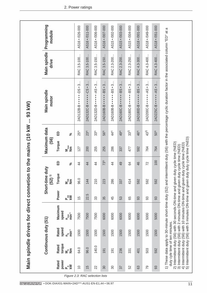
1) T
hese
dat
a ap
ply
to 3
0-m
inut
e sh
ort-
time
duty
(S
2) a
nd in
term
itten
t dut
y (S
6) w
ith th
e pe
rcen
tage
cyc
lic d
urat
ion
fact
or in
the
asso
ciat
ed c
olum
n "E
D"
at a
duty
cyl
e tim
e of
ten
min
utes
.2)
Inte
rmitt
ent d
uty
(S6)
with
30
seco
nds
ON
-tim
e an
d gi
ven
duty
cyc
le ti
me
(%E
D)
3) In
term
itten
t dut
y (S
6) w
ith 2
min
utes
ON
-tim
e an
d gi
ven
duty
cyc
le ti
me
(%E
D)
4) In
term
itten
t dut
y (S
6) w
ith 1
0 m
inut
es O
N-t
ime
and
give
n du
ty c
ycle
tim
e (%
ED
)5)
Inte
rmitt
ent d
uty
(S6)
with
5 m
inut
es O
N-t
ime
and
give
n du
ty d
uty
cycl
e tim
e (%
ED
)
2. Power ratings
Figure 2.3: RAC selection lists
RAC selection list
12• DOK-DIAX01-MAIN+2AD***-AUS1-EN-E1,44 • 06.97
2. Power ratings
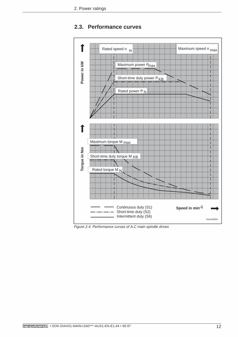
2.3. Performance curves
Kenn2ADH
Rated speed n Maximum speed n
Maximum power P
Pow
er in
kW
Torq
ue in
Nm
Speed in min -1
Short-time duty power P
Rated power P
Maximum torque M
Short-time duty torque M
Rated torque M
N max
max
KB
N
max
KB
N
Continuous duty (S1)Short-time duty (S2)Intermittent duty (S6)
Figure 2.4: Performance curves of A.C main spindle drives
13• DOK-DIAX01-MAIN+2AD***-AUS1-EN-E1,44 • 06.97
2. Power ratings
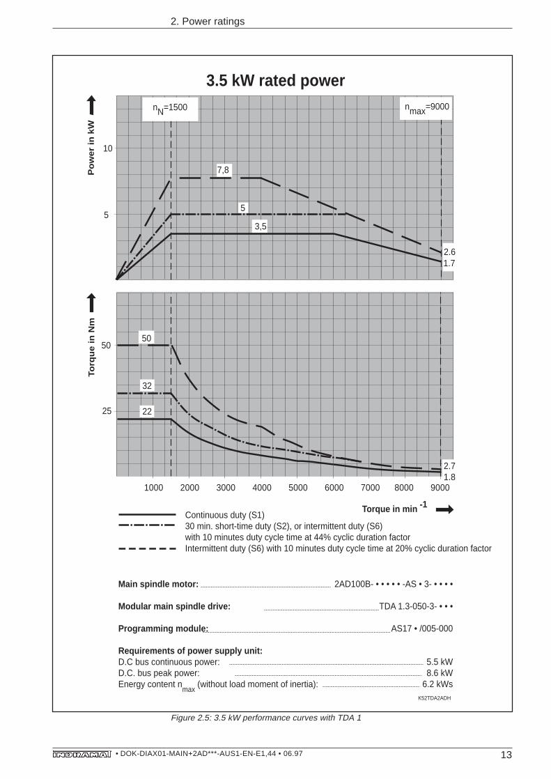
1000 2000 3000 4000 5000 6000 7000 8000 9000
5
10
50
K52TDA2ADH
nN=1500 nmax=9000
25
3,5
1.72.6
2.71.8
32
7,8
3.5 kW rated power
Main spindle motor:
Modular main spindle drive:
Programming module:
Requirements of power supply unit:D.C bus continuous power:D.C. bus peak power:Energy content n
max (without load moment of inertia):
2AD100B- • • • • • -AS • 3- • • • •
TDA 1.3-050-3- • • •
AS17 • /005-000
5.5 kW8.6 kW
6.2 kWs
Po
we
r in
kW
Torq
ue
in N
m
Torque in min -1Continuous duty (S1)30 min. short-time duty (S2), or intermittent duty (S6)with 10 minutes duty cycle time at 44% cyclic duration factorIntermittent duty (S6) with 10 minutes duty cycle time at 20% cyclic duration factor
5
50
22
Figure 2.5: 3.5 kW performance curves with TDA 1
14• DOK-DIAX01-MAIN+2AD***-AUS1-EN-E1,44 • 06.97
2. Power ratings
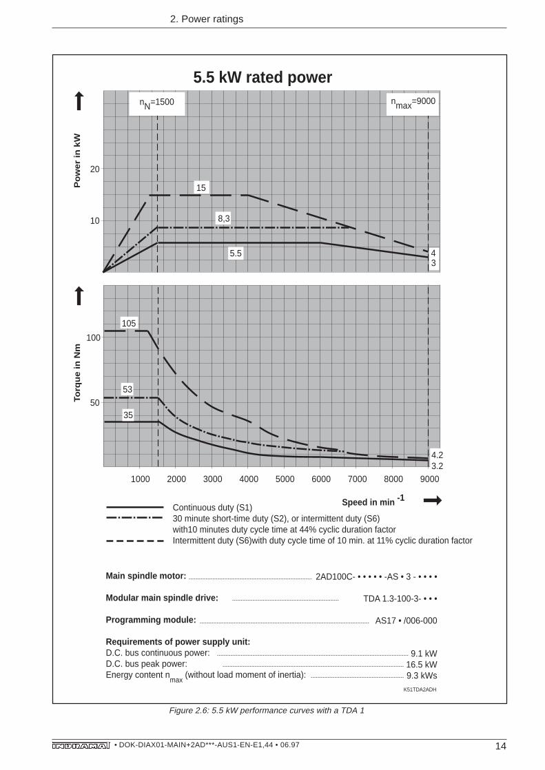
1000 2000 3000 4000 5000 6000 7000 8000 9000
10
20
50
100
105
K51TDA2ADH
nN=1500 nmax=9000
5.5
8,3
15
53
34
4.23.2
5.5 kW rated power
35
Main spindle motor:
Modular main spindle drive:
Programming module:
Requirements of power supply unit:D.C. bus continuous power:D.C. bus peak power:Energy content n
max (without load moment of inertia):
2AD100C- • • • • • -AS • 3 - • • • •
TDA 1.3-100-3- • • •
AS17 • /006-000
9.1 kW16.5 kW9.3 kWs
Continuous duty (S1)30 minute short-time duty (S2), or intermittent duty (S6)with10 minutes duty cycle time at 44% cyclic duration factorIntermittent duty (S6)with duty cycle time of 10 min. at 11% cyclic duration factor
Po
we
r in
kW
Torq
ue
in N
m
Speed in min -1
Figure 2.6: 5.5 kW performance curves with a TDA 1
15• DOK-DIAX01-MAIN+2AD***-AUS1-EN-E1,44 • 06.97
2. Power ratings
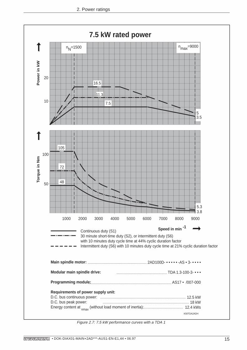
Figure 2.7: 7.5 kW performance curves with a TDA 1
1000 2000 3000 4000 5000 6000 7000 8000 9000
10
20
50
100
105
K50TDA2ADH
nN=1500 nmax=9000
7.5
11,3
16.5
72
7.5 kW rated power
3.55
5.33.8
48
Main spindle motor:
Modular main spindle drive:
Programming module:
Requirements of power supply unit:D.C. bus continuous power:D.C. bus peak power:Energy content at
nmax (without load moment of inertia):
2AD100D- • • • • • -AS • 3- • • • •
TDA 1.3-100-3- • • •
AS17 • /007-000
12.5 kW18 kW
12.4 kWs
Continuous duty (S1)30 minute short-time duty (S2), or intermittent duty (S6)with 10 minutes duty cycle time at 44% cyclic duration factorIntermittent duty (S6) with 10 minutes duty cycle time at 21% cyclic duration factor
Po
we
r in
kW
Torq
ue
in N
m
Speed in min -1
16• DOK-DIAX01-MAIN+2AD***-AUS1-EN-E1,44 • 06.97
2. Power ratings
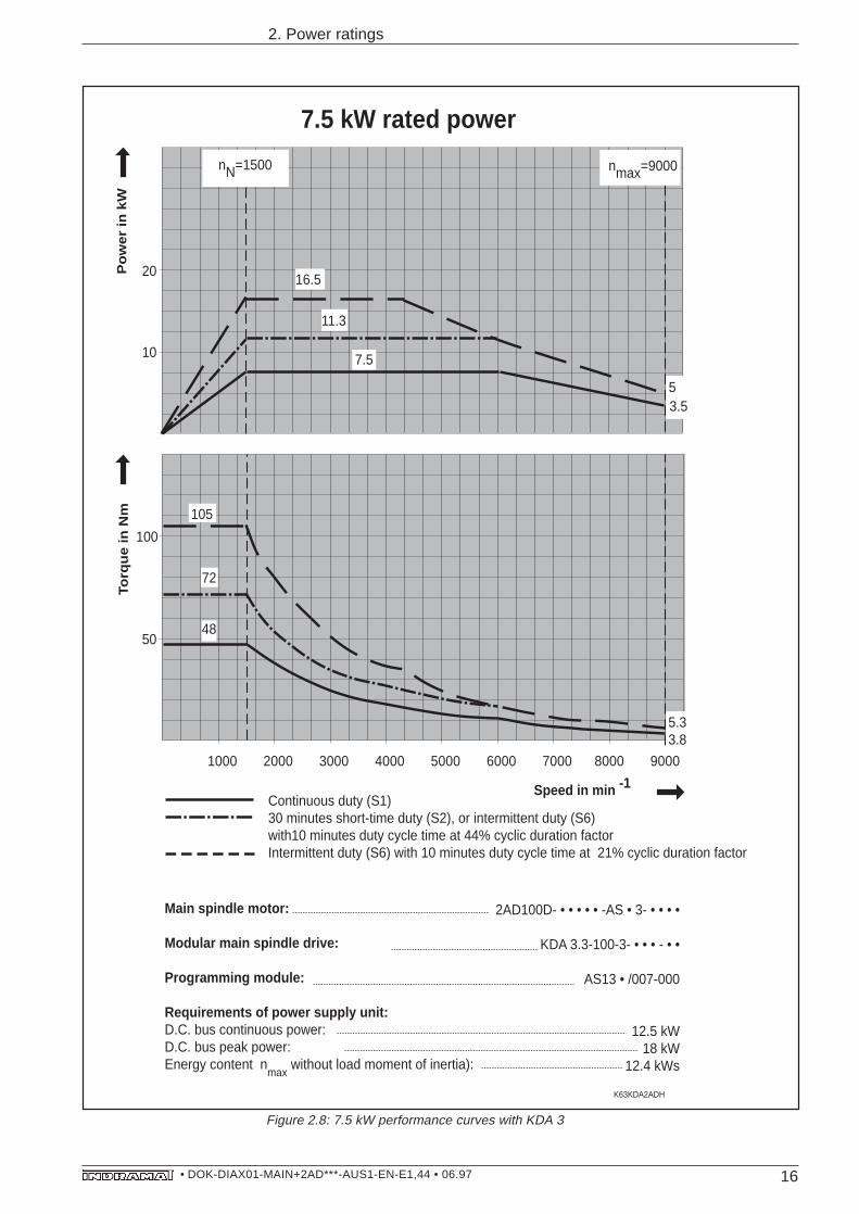
Figure 2.8: 7.5 kW performance curves with KDA 3
1000 2000 3000 4000 5000 6000 7000 8000 9000
10
20
50
100
105
5.33.8
nN=1500 nmax=9000
7.5
11.3
16.5
72
7.5 kW rated power
3.55
K63KDA2ADH
48
Main spindle motor:
Modular main spindle drive:
Programming module:
Requirements of power supply unit:D.C. bus continuous power:D.C. bus peak power:Energy content n
max without load moment of inertia):
2AD100D- • • • • • -AS • 3- • • • •
KDA 3.3-100-3- • • • - • •
AS13 • /007-000
12.5 kW18 kW
12.4 kWs
Continuous duty (S1)30 minutes short-time duty (S2), or intermittent duty (S6)with10 minutes duty cycle time at 44% cyclic duration factorIntermittent duty (S6) with 10 minutes duty cycle time at 21% cyclic duration factor
Po
we
r in
kW
Torq
ue
in N
m
Speed in min -1
17• DOK-DIAX01-MAIN+2AD***-AUS1-EN-E1,44 • 06.97
2. Power ratings
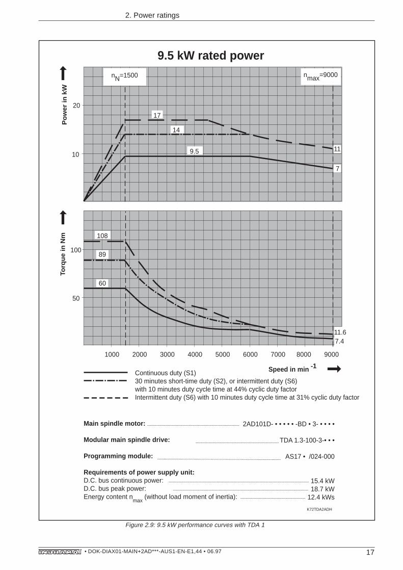
Figure 2.9: 9.5 kW performance curves with TDA 1
1000 2000 3000 4000 5000 6000 7000 8000 9000
K72TDA2ADH
nN=1500 nmax=9000
50
100
108
10
20
17
14
9.5
7.4
89
60
11.6
9.5 kW rated power
11
7
Main spindle motor:
Modular main spindle drive:
Programming module:
Requirements of power supply unit:D.C. bus continuous power:D.C. bus peak power:Energy content n
max (without load moment of inertia):
2AD101D- • • • • • -BD • 3- • • • •
TDA 1.3-100-3-• • •
AS17 • /024-000
15.4 kW18.7 kW
12.4 kWs
Continuous duty (S1)30 minutes short-time duty (S2), or intermittent duty (S6)with 10 minutes duty cycle time at 44% cyclic duty factorIntermittent duty (S6) with 10 minutes duty cycle time at 31% cyclic duty factor
Pow
er in
kW
Torq
ue in
Nm
Speed in min -1
18• DOK-DIAX01-MAIN+2AD***-AUS1-EN-E1,44 • 06.97
2. Power ratings
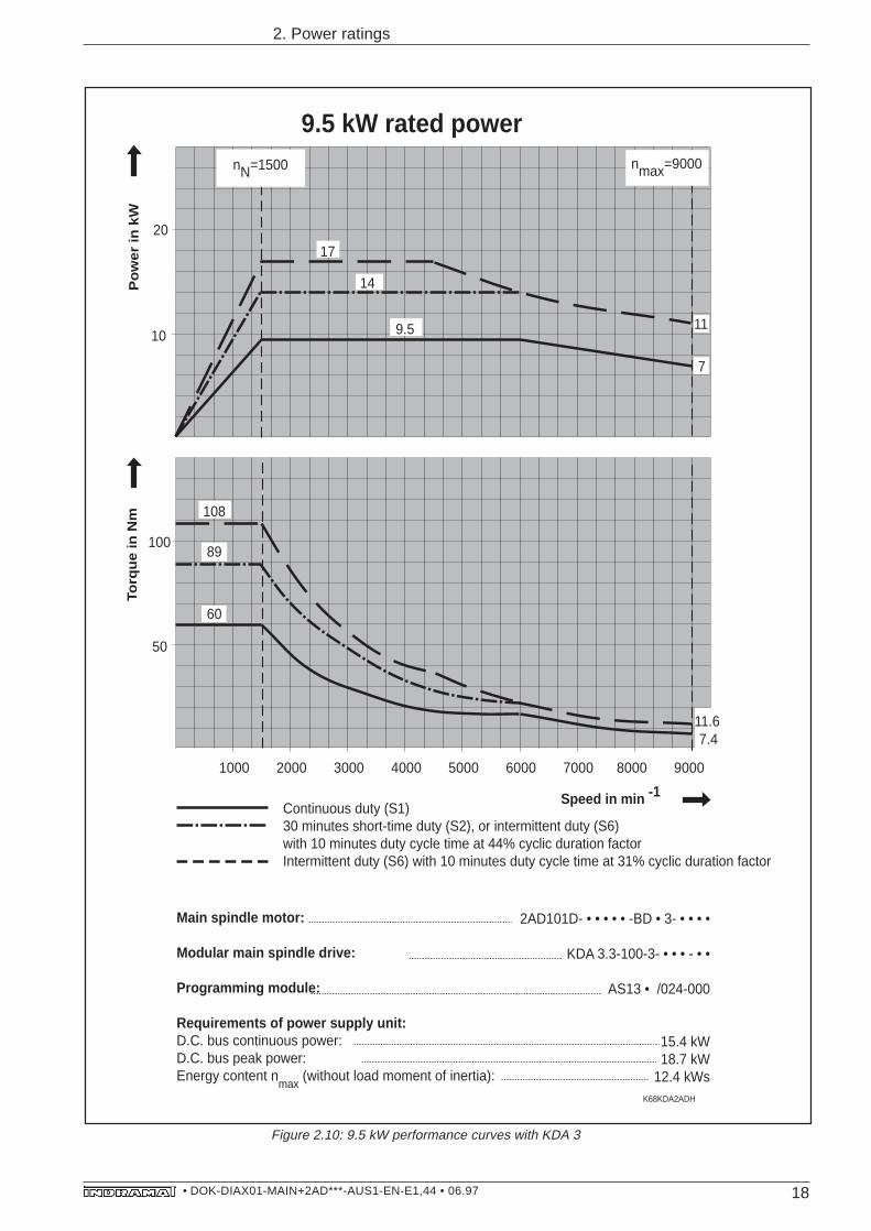
Figure 2.10: 9.5 kW performance curves with KDA 3
1000 2000 3000 4000 5000 6000 7000 8000 9000
nN=1500 nmax=9000
50
100
108
10
20
17
14
9.5
7.4
89
60
11.6
K68KDA2ADH
9.5 kW rated power
11
7
Main spindle motor:
Modular main spindle drive:
Programming module:
Requirements of power supply unit:D.C. bus continuous power:D.C. bus peak power:Energy content n
max (without load moment of inertia):
2AD101D- • • • • • -BD • 3- • • • •
KDA 3.3-100-3- • • • - • •
AS13 • /024-000
15.4 kW18.7 kW
12.4 kWs
Continuous duty (S1)30 minutes short-time duty (S2), or intermittent duty (S6)with 10 minutes duty cycle time at 44% cyclic duration factorIntermittent duty (S6) with 10 minutes duty cycle time at 31% cyclic duration factor
Po
we
r in
kW
Torq
ue
in N
m
Speed in min -1
19• DOK-DIAX01-MAIN+2AD***-AUS1-EN-E1,44 • 06.97
2. Power ratings
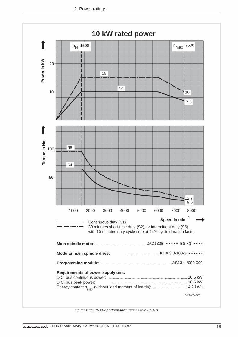
Figure 2.11: 10 kW performance curves with KDA 3
Main spindle motor:
Modular main spindle drive:
Programming module:
Requirements of power supply unit:D.C. bus continuous power:D.C. bus peak power:Energy content n
max (without load moment of inertia):
2AD132B- • • • • • -BS • 3- • • • •
KDA 3.3-100-3- • • • - • •
AS13 • /009-000
16.5 kW16.5 kW
14.2 kWs
Continuous duty (S1)30 minutes short-time duty (S2), or intermittent duty (S6)with 10 minutes duty cycle time at 44% cyclic duration factor
1000 2000 3000 4000 5000 6000 7000 8000
10
20
nmax=7500nN=1500
50
100
12.79.5
10
7.5
K64KDA2ADH
10 kW rated power
15
10
96
64
Pow
er in
kW
Torq
ue in
Nm
Speed in min -1
20• DOK-DIAX01-MAIN+2AD***-AUS1-EN-E1,44 • 06.97
2. Power ratings
1000 2000 3000 4000 5000 6000 7000 8000
10
20
nmax=7500nN=1500
50
100
150
165
64
12.79.5
10
7.5
K67KDA2ADH
10 kW rated power
20
15
10
96
Main spindle motor:
Modular main spindle drive:
Programming module:
Requirements of power supply unit:D.C. bus continuous power:D.C. bus peak power:Energy content n
max (without load moment of inertia):
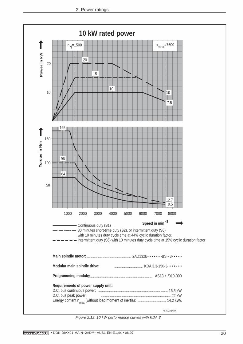
2AD132B- • • • • • -BS • 3- • • • •
KDA 3.3-150-3- • • • - • •
AS13 • /019-000
16.5 kW22 kW
14.2 kWs
Continuous duty (S1)30 minutes short-time duty (S2), or intermittent duty (S6)with 10 minutes duty cycle time at 44% cyclic duration factor.Intermittent duty (S6) with 10 minutes duty cycle time at 15% cyclic duration factor
Po
we
r in
kW
To
rqu
e in
Nm
Speed in min -1
Figure 2.12: 10 kW performance curves with KDA 3
21• DOK-DIAX01-MAIN+2AD***-AUS1-EN-E1,44 • 06.97
2. Power ratings
1000 2000 3000 4000 5000 6000 7000 8000
K16RAC2ADH
nN=1500 nmax=7500
10
20
50
100 96
64
127
15
1913
10 kW rated power
10
20
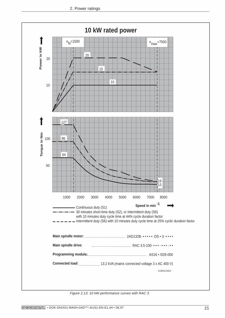
Main spindle motor:
Main spindle drive:
Programming module:
Connected load:
2AD132B- • • • • • -DS • 3- • • • •
RAC 3.5-100- • • • - • • • - • •
AS16 • /026-000
13.2 kVA (mains connected voltage 3 x AC 400 V)
Continuous duty (S1)30 minutes short-time duty (S2), or intermittent duty (S6)with 10 minutes duty cycle time at 44% cycle duration factorIntermittent duty (S6) with 10 minutes duty cycle time at 25% cyclic duration factor
Po
we
r in
kW
To
rqu
e in
Nm
Speed in min -1
Figure 2.13: 10 kW performance curves with RAC 3
22• DOK-DIAX01-MAIN+2AD***-AUS1-EN-E1,44 • 06.97
2. Power ratings
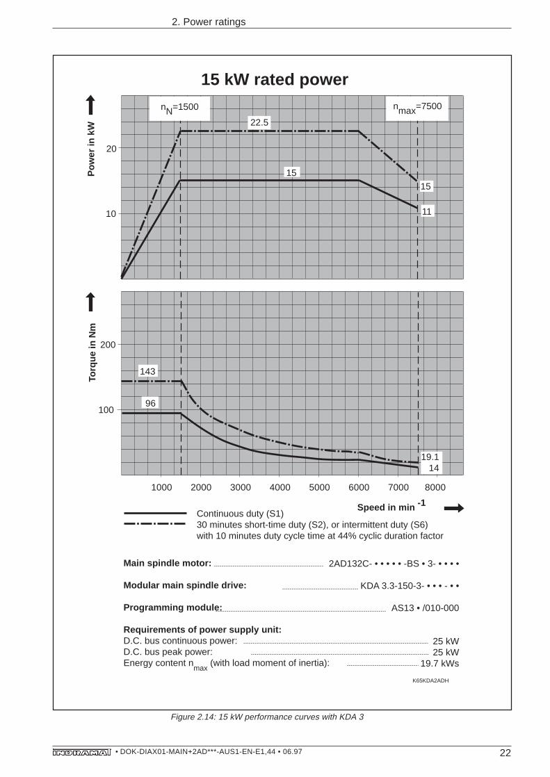
Figure 2.14: 15 kW performance curves with KDA 3
1000 2000 3000 4000 5000 6000 7000 8000
10
20
nmax=7500nN=1500
200
100
143
19.114
11
K65KDA2ADH
15
22.5
15 kW rated power
96
15
Main spindle motor:
Modular main spindle drive:
Programming module:
Requirements of power supply unit:D.C. bus continuous power:D.C. bus peak power:Energy content n
max (with load moment of inertia):
2AD132C- • • • • • -BS • 3- • • • •
KDA 3.3-150-3- • • • - • •
AS13 • /010-000
25 kW25 kW
19.7 kWs
Continuous duty (S1)30 minutes short-time duty (S2), or intermittent duty (S6)with 10 minutes duty cycle time at 44% cyclic duration factor
Pow
er in
kW
Torq
ue in
Nm
Speed in min -1
23• DOK-DIAX01-MAIN+2AD***-AUS1-EN-E1,44 • 06.97
2. Power ratings
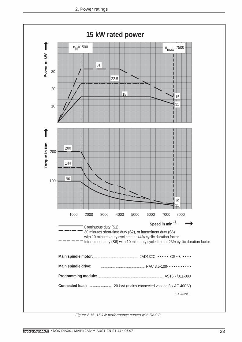
Figure 2.15: 15 kW performance curves with RAC 3
1000 2000 3000 4000 5000 6000 7000 8000
K12RAC2ADH
nN=1500 nmax=7500
10
30
15
11
15
22.5
31
1911
100
200200
144
96
20
15 kW rated power
Main spindle motor:
Main spindle drive:
Programming module:
Connected load:
2AD132C- • • • • • -CS • 3- • • • •
RAC 3.5-100- • • • - • • • - • •
AS16 • /011-000
20 kVA (mains connected voltage 3 x AC 400 V)
Continuous duty (S1)30 minutes short-time duty (S2), or intermittent duty (S6)with 10 minutes duty cycl time at 44% cyclic duration factorIntermittent duty (S6) with 10 min. duty cycle time at 23% cyclic duration factor
Po
we
r in
kW
To
rqu
e in
Nm
Speed in min -1
24• DOK-DIAX01-MAIN+2AD***-AUS1-EN-E1,44 • 06.97
2. Power ratings
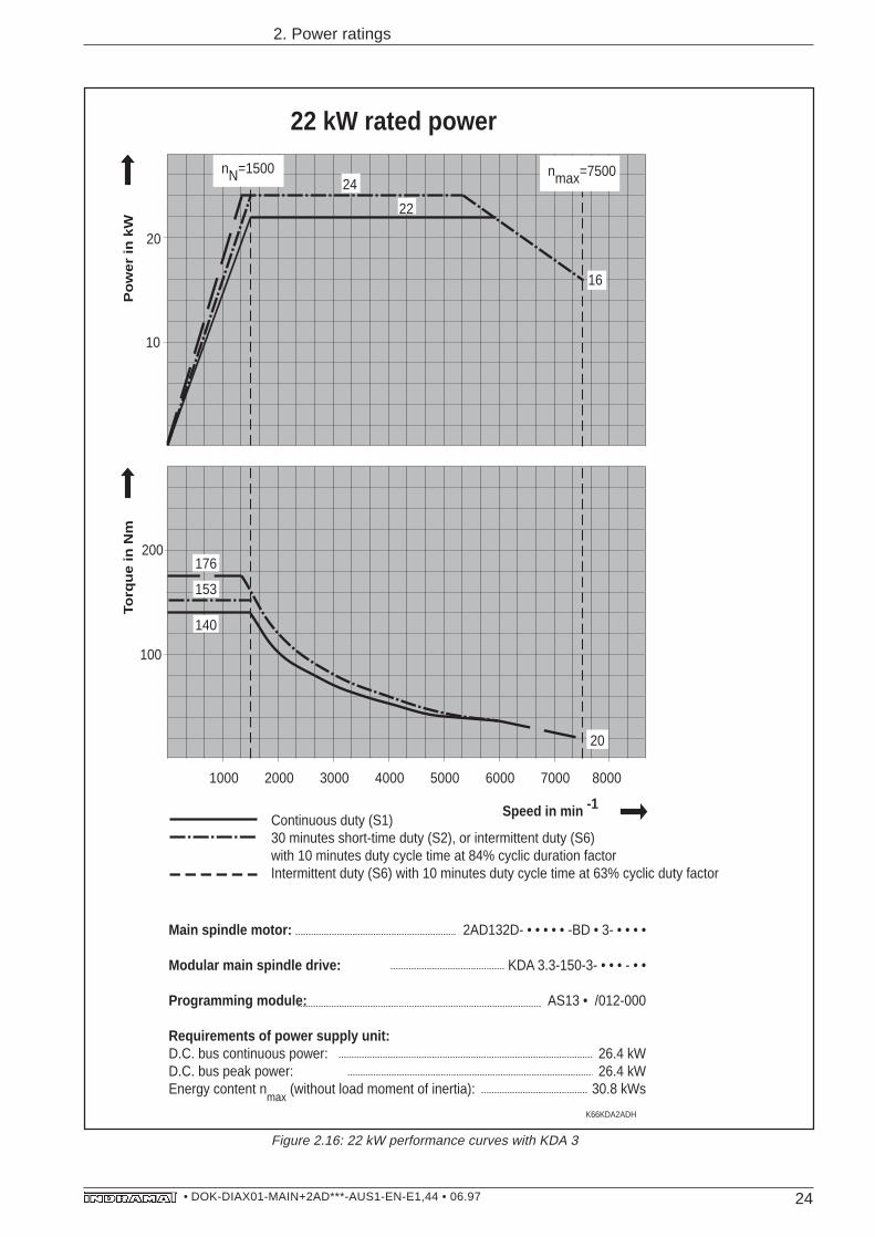
Figure 2.16: 22 kW performance curves with KDA 3
1000 2000 3000 4000 5000 6000 7000 8000
10
20
nmax=7500nN=1500
100
200
20
16
176
153
140
K66KDA2ADH
22 kW rated power
24
22
Main spindle motor:
Modular main spindle drive:
Programming module:
Requirements of power supply unit:D.C. bus continuous power:D.C. bus peak power:Energy content n
max (without load moment of inertia):
2AD132D- • • • • • -BD • 3- • • • •
KDA 3.3-150-3- • • • - • •
AS13 • /012-000
26.4 kW26.4 kW
30.8 kWs
Continuous duty (S1)30 minutes short-time duty (S2), or intermittent duty (S6)with 10 minutes duty cycle time at 84% cyclic duration factorIntermittent duty (S6) with 10 minutes duty cycle time at 63% cyclic duty factor
Po
we
r in
kW
To
rqu
e in
Nm
Speed in min -1
25• DOK-DIAX01-MAIN+2AD***-AUS1-EN-E1,44 • 06.97
2. Power ratings
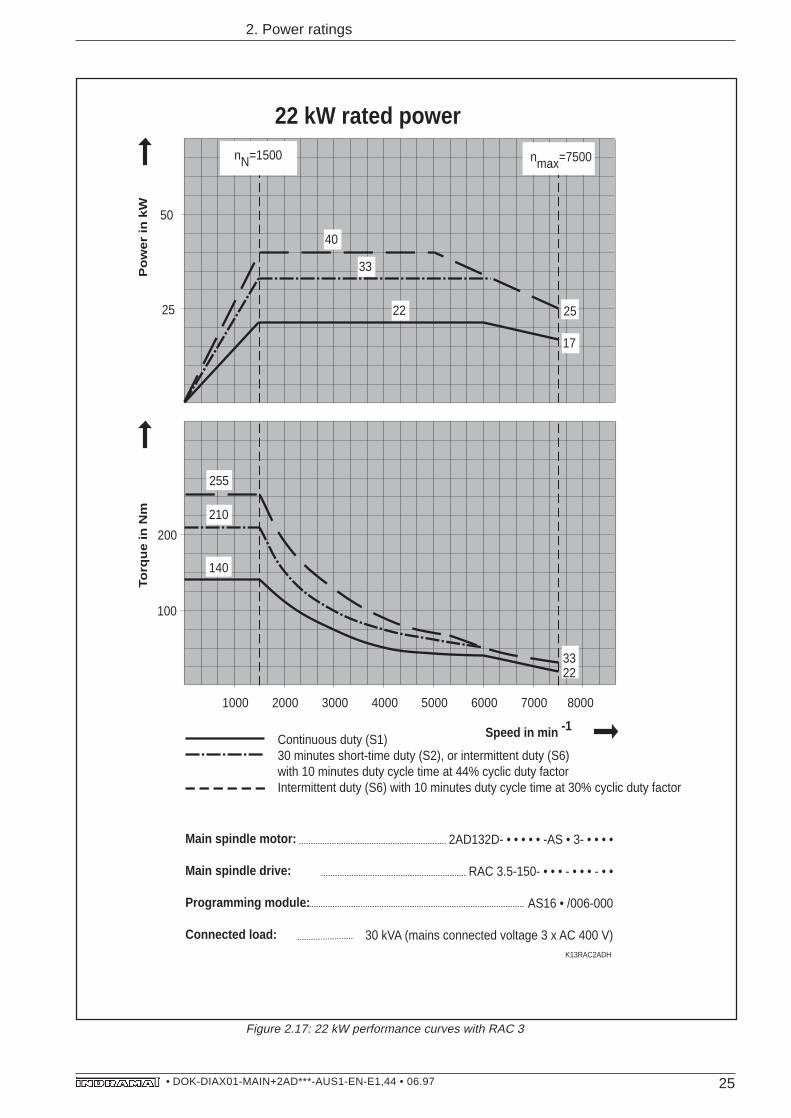
Figure 2.17: 22 kW performance curves with RAC 3
1000 2000 3000 4000 5000 6000 7000 8000
nN=1500 nmax=7500
50
25 25
17
22
33
40
3322
100
200
255
210
140
K13RAC2ADH
22 kW rated power
Main spindle motor:
Main spindle drive:
Programming module:
Connected load:
2AD132D- • • • • • -AS • 3- • • • •
RAC 3.5-150- • • • - • • • - • •
AS16 • /006-000
30 kVA (mains connected voltage 3 x AC 400 V)
Continuous duty (S1)30 minutes short-time duty (S2), or intermittent duty (S6)with 10 minutes duty cycle time at 44% cyclic duty factorIntermittent duty (S6) with 10 minutes duty cycle time at 30% cyclic duty factor
Po
we
r in
kW
To
rqu
e in
Nm
Speed in min -1
26• DOK-DIAX01-MAIN+2AD***-AUS1-EN-E1,44 • 06.97
2. Power ratings
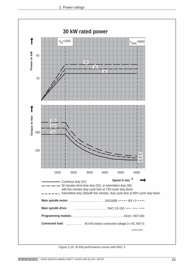
Figure 2.18: 30 kW performance curves with RAC 3
1000 2000 3000 4000 5000 6000
nN=1500 nmax=6000
25
50
645648
200
255
191
100
K14RAC2ADH
30 kW rated power
30
40
Main spindle motor:
Main spindle drive:
Programming module:
Connected load:
2AD160B- • • • • • -BS • 3- • • • •
RAC 3.5-150- • • • - • • • - • • •
AS16 • /007-000
40 kVA (mains connected voltage 3 x AC 400 V)
Continous duty (S1)30 minutes short-time duty (S2), or intermittent duty (S6)with five minutes duty cycle time at 73% cyclic duty factorIntermittent duty (S6)with five minutes duty cycle time at 56% cyclic duty factor
35
223
Po
we
r in
kW
To
rqu
e in
Nm
Speed in min -1
27• DOK-DIAX01-MAIN+2AD***-AUS1-EN-E1,44 • 06.97
2. Power ratings
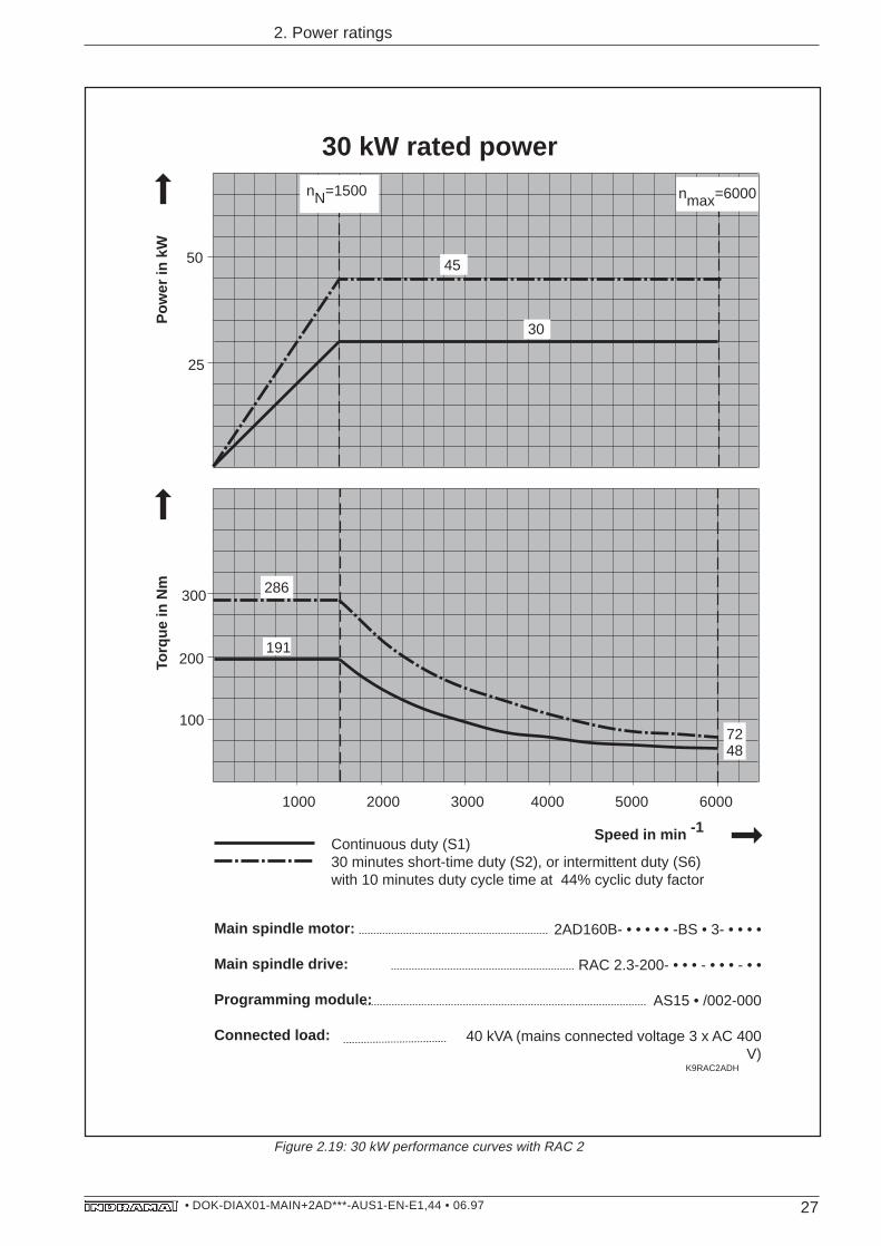
Figure 2.19: 30 kW performance curves with RAC 2
1000 2000 3000 4000 5000 6000
K9RAC2ADH
nN=1500 nmax=6000
25
50
7248
200
300 286
191
100
30 kW rated power
45
30
Main spindle motor:
Main spindle drive:
Programming module:
Connected load:
2AD160B- • • • • • -BS • 3- • • • •
RAC 2.3-200- • • • - • • • - • •
AS15 • /002-000
40 kVA (mains connected voltage 3 x AC 400 V)
Continuous duty (S1)30 minutes short-time duty (S2), or intermittent duty (S6)with 10 minutes duty cycle time at 44% cyclic duty factor
Pow
er in
kW
Torq
ue in
Nm
Speed in min -1
28• DOK-DIAX01-MAIN+2AD***-AUS1-EN-E1,44 • 06.97
2. Power ratings
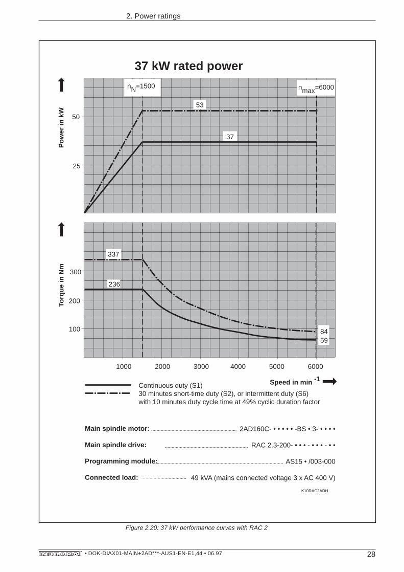
Figure 2.20: 37 kW performance curves with RAC 2
1000 2000 3000 4000 5000 6000
K10RAC2ADH
nN=1500 nmax=6000
25
50
8459
200
300
337
236
100
37
37 kW rated power
53
Main spindle motor:
Main spindle drive:
Programming module:
Connected load:
2AD160C- • • • • • -BS • 3- • • • •
RAC 2.3-200- • • • - • • • - • •
AS15 • /003-000
49 kVA (mains connected voltage 3 x AC 400 V)
Continuous duty (S1)30 minutes short-time duty (S2), or intermittent duty (S6)with 10 minutes duty cycle time at 49% cyclic duration factor
Pow
er in
kW
Torq
ue in
Nm
Speed in min -1
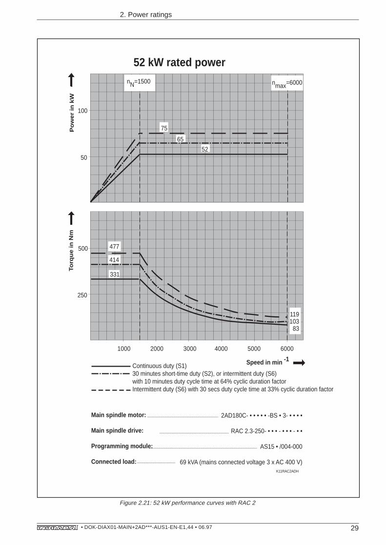
29• DOK-DIAX01-MAIN+2AD***-AUS1-EN-E1,44 • 06.97
2. Power ratings
1000 2000 3000 4000 5000 6000
K11RAC2ADH
nN=1500 nmax=6000
50
100
52
65
75
119103
83
250
500 477
414
331
52 kW rated power
Main spindle motor:
Main spindle drive:
Programming module:
Connected load:
2AD180C- • • • • • -BS • 3- • • • •
RAC 2.3-250- • • • - • • • - • •
AS15 • /004-000
69 kVA (mains connected voltage 3 x AC 400 V)
Continuous duty (S1)30 minutes short-time duty (S2), or intermittent duty (S6)with 10 minutes duty cycle time at 64% cyclic duration factorIntermittent duty (S6) with 30 secs duty cycle time at 33% cyclic duration factor
Po
we
r in
kW
To
rqu
e in
Nm
Speed in min -1
Figure 2.21: 52 kW performance curves with RAC 2
30• DOK-DIAX01-MAIN+2AD***-AUS1-EN-E1,44 • 06.97
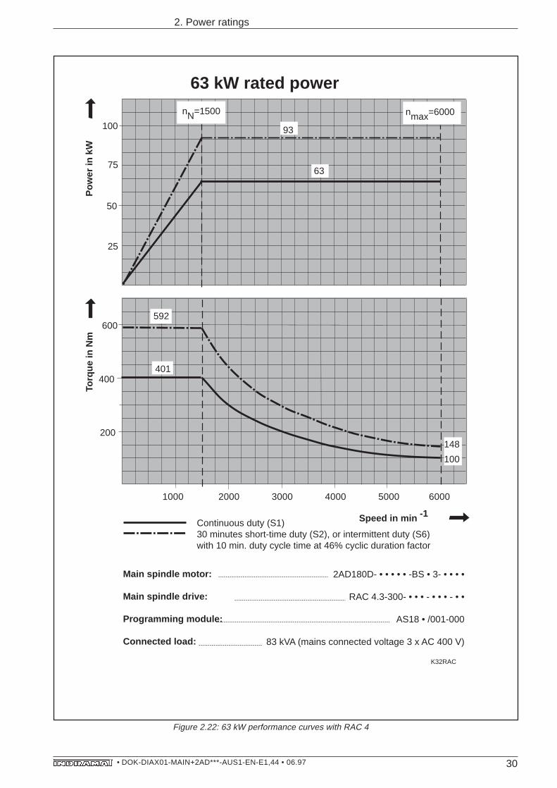
2. Power ratings
Figure 2.22: 63 kW performance curves with RAC 4
200
1000 2000 3000 4000 5000 6000
K32RAC
nN=1500 nmax=6000
50
25
93
63
600
400
75
100
148
100
401
592
63 kW rated power
Main spindle motor:
Main spindle drive:
Programming module:
Connected load:
2AD180D- • • • • • -BS • 3- • • • •
RAC 4.3-300- • • • - • • • - • •
AS18 • /001-000
83 kVA (mains connected voltage 3 x AC 400 V)
Continuous duty (S1)30 minutes short-time duty (S2), or intermittent duty (S6)with 10 min. duty cycle time at 46% cyclic duration factor
Pow
er in
kW
Torq
ue in
Nm
Speed in min -1
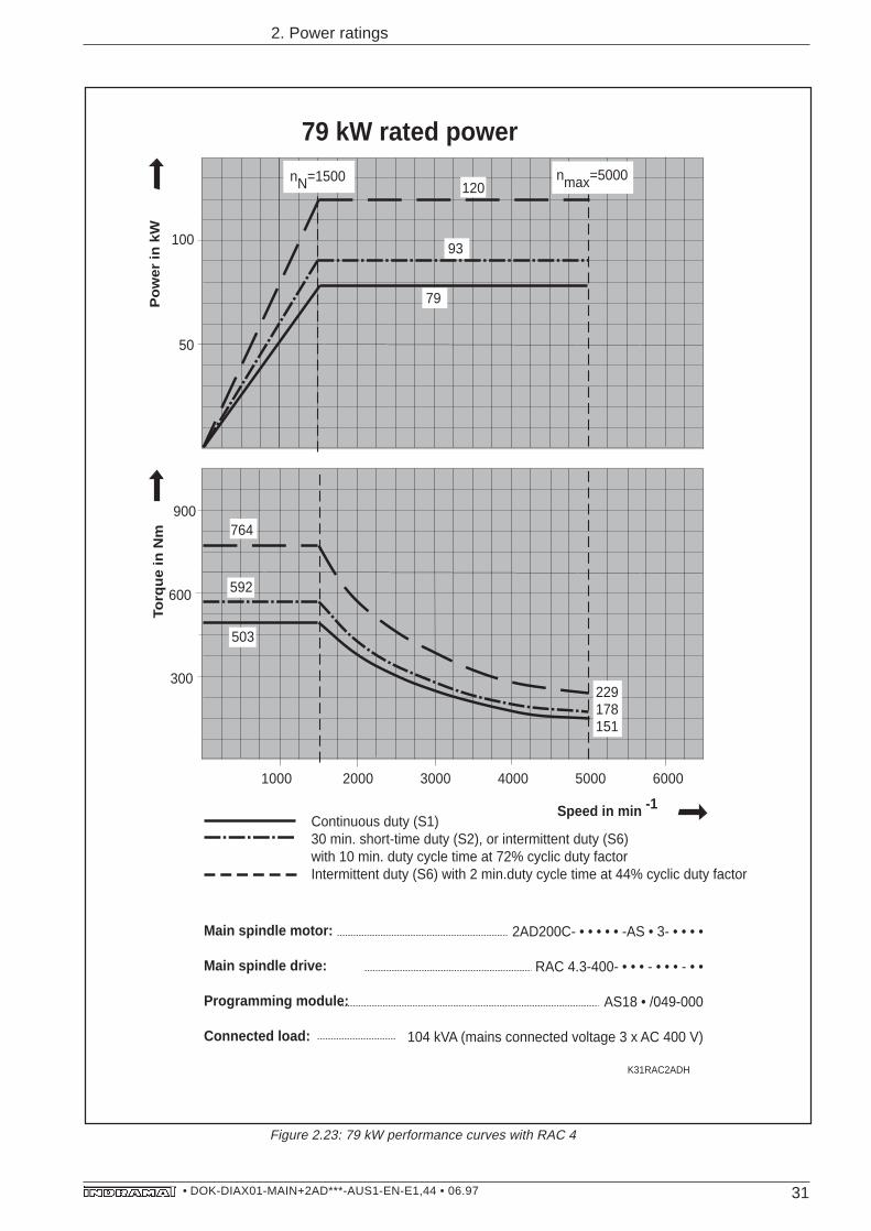
31• DOK-DIAX01-MAIN+2AD***-AUS1-EN-E1,44 • 06.97
2. Power ratings
300
1000 2000 3000 4000 5000 6000
K31RAC2ADH
nN=1500 nmax=5000
100
50
120
79
900
600
764
503
229178151
79 kW rated power
93
592
Main spindle motor:
Main spindle drive:
Programming module:
Connected load:
2AD200C- • • • • • -AS • 3- • • • •
RAC 4.3-400- • • • - • • • - • •
AS18 • /049-000
104 kVA (mains connected voltage 3 x AC 400 V)
Continuous duty (S1)30 min. short-time duty (S2), or intermittent duty (S6)with 10 min. duty cycle time at 72% cyclic duty factorIntermittent duty (S6) with 2 min.duty cycle time at 44% cyclic duty factor
Po
we
r in
kW
Torq
ue
in N
m
Speed in min -1
Figure 2.23: 79 kW performance curves with RAC 4
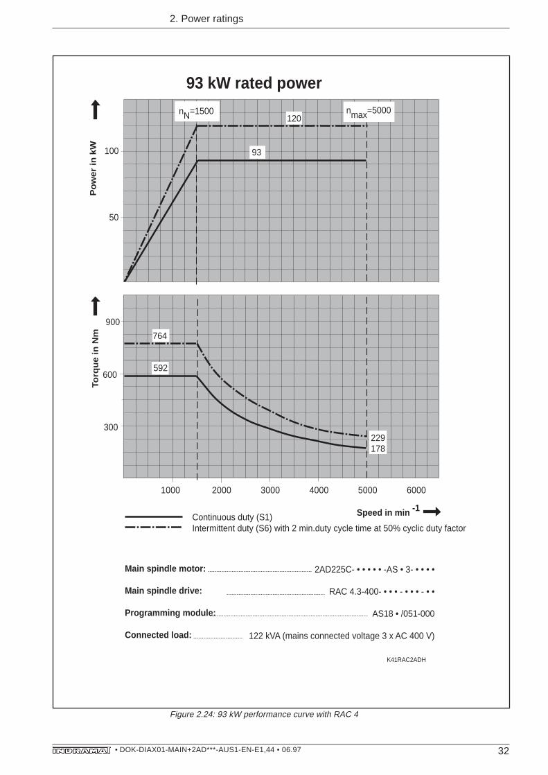
32• DOK-DIAX01-MAIN+2AD***-AUS1-EN-E1,44 • 06.97
2. Power ratings
Figure 2.24: 93 kW performance curve with RAC 4
300
1000 2000 3000 4000 5000 6000
K41RAC2ADH
nN=1500 nmax=5000
100
50
120
93
900
600
229178
93 kW rated power
Main spindle motor:
Main spindle drive:
Programming module:
Connected load:
2AD225C- • • • • • -AS • 3- • • • •
RAC 4.3-400- • • • - • • • - • •
AS18 • /051-000
122 kVA (mains connected voltage 3 x AC 400 V)
Continuous duty (S1)Intermittent duty (S6) with 2 min.duty cycle time at 50% cyclic duty factor
764
592
Po
we
r in
kW
Torq
ue
in N
m
Speed in min -1
33• DOK-DIAX01-MAIN+2AD***-AUS1-EN-E1,44 • 06.97
3. Functions and features of main spindle drives
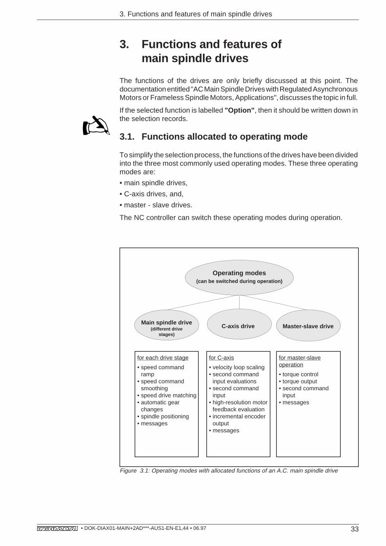
Figure 3.1: Operating modes with allocated functions of an A.C. main spindle drive
for each drive stage
• speed commandramp
• speed commandsmoothing
• speed drive matching• automatic gear
changes• spindle positioning• messages
for C-axis
• velocity loop scaling• second command
input evaluations• second command
input• high-resolution motor
feedback evaluation• incremental encoder
output• messages
for master-slaveoperation
• torque control• torque output• second command
input• messages
Main spindle drive(different drive
stages)
Master-slave drive
Operating modes(can be switched during operation)
C-axis drive
3. Functions and features ofmain spindle drives
The functions of the drives are only briefly discussed at this point. Thedocumentation entitled "AC Main Spindle Drives with Regulated AsynchronousMotors or Frameless Spindle Motors, Applications", discusses the topic in full.
If the selected function is labelled "Option" , then it should be written down inthe selection records.
3.1. Functions allocated to operating mode
To simplify the selection process, the functions of the drives have been dividedinto the three most commonly used operating modes. These three operatingmodes are:
• main spindle drives,
• C-axis drives, and,
• master - slave drives.
The NC controller can switch these operating modes during operation.
34• DOK-DIAX01-MAIN+2AD***-AUS1-EN-E1,44 • 06.97
3. Functions and features of main spindle drives
3.1.1. Changing the operating mode during operation
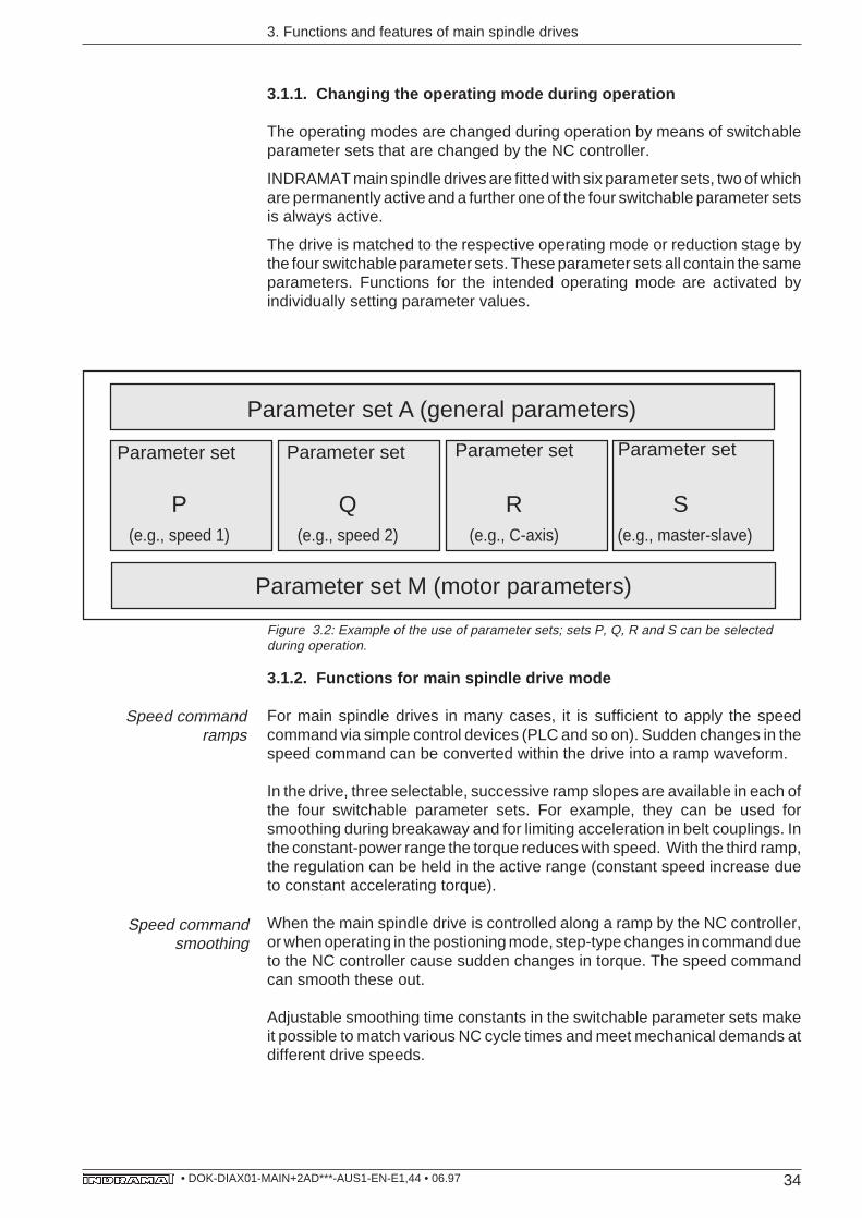
The operating modes are changed during operation by means of switchableparameter sets that are changed by the NC controller.
INDRAMAT main spindle drives are fitted with six parameter sets, two of whichare permanently active and a further one of the four switchable parameter setsis always active.
The drive is matched to the respective operating mode or reduction stage bythe four switchable parameter sets. These parameter sets all contain the sameparameters. Functions for the intended operating mode are activated byindividually setting parameter values.
Parameter set M (motor parameters)
Parameter set A (general parameters)
Figure 3.2: Example of the use of parameter sets; sets P, Q, R and S can be selectedduring operation.
3.1.2. Functions for main spindle drive mode
For main spindle drives in many cases, it is sufficient to apply the speedcommand via simple control devices (PLC and so on). Sudden changes in thespeed command can be converted within the drive into a ramp waveform.
In the drive, three selectable, successive ramp slopes are available in each ofthe four switchable parameter sets. For example, they can be used forsmoothing during breakaway and for limiting acceleration in belt couplings. Inthe constant-power range the torque reduces with speed. With the third ramp,the regulation can be held in the active range (constant speed increase dueto constant accelerating torque).
When the main spindle drive is controlled along a ramp by the NC controller,or when operating in the postioning mode, step-type changes in command dueto the NC controller cause sudden changes in torque. The speed commandcan smooth these out.
Adjustable smoothing time constants in the switchable parameter sets makeit possible to match various NC cycle times and meet mechanical demands atdifferent drive speeds.
Speed commandramps
Parameter set Parameter set Parameter setParameter set
Speed commandsmoothing
P Q R S(e.g., speed 1) (e.g., speed 2) (e.g., C-axis) (e.g., master-slave)
35• DOK-DIAX01-MAIN+2AD***-AUS1-EN-E1,44 • 06.97
3. Functions and features of main spindle drives
The machine's different mechanical arrangements during gear change, orchange in the drive's operating mode, make different demands of speedregulation.
Specific values for matching the speed drive can be set in each of theswitchable parameter sets.
Due to the wide speed range, the main spindle drive operates in the constant-torque or constant-power range. Two different speed parameters per parameterset, which can be switched according to speed, are available for matching theresulting, different requirements.
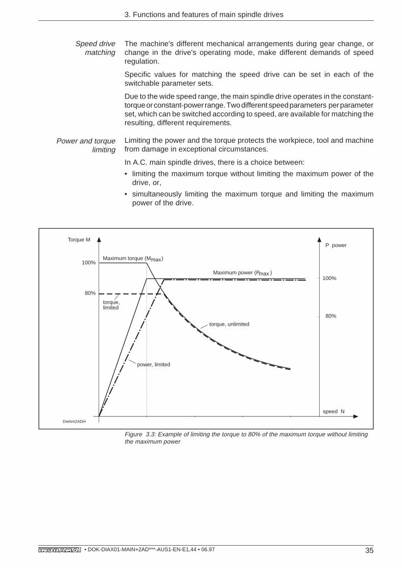
Limiting the power and the torque protects the workpiece, tool and machinefrom damage in exceptional circumstances.
In A.C. main spindle drives, there is a choice between:
• limiting the maximum torque without limiting the maximum power of thedrive, or,
• simultaneously limiting the maximum torque and limiting the maximumpower of the drive.
Speed drivematching
Figure 3.3: Example of limiting the torque to 80% of the maximum torque without limitingthe maximum power
Drehm2ADH
Maximum torque (M )
Torque M
100%
80%
Maximum power (P )
power, limited
P power
100%
80%
torque, unlimited
speed N
max
max
torque, limited
Power and torquelimiting
36• DOK-DIAX01-MAIN+2AD***-AUS1-EN-E1,44 • 06.97
3. Functions and features of main spindle drives
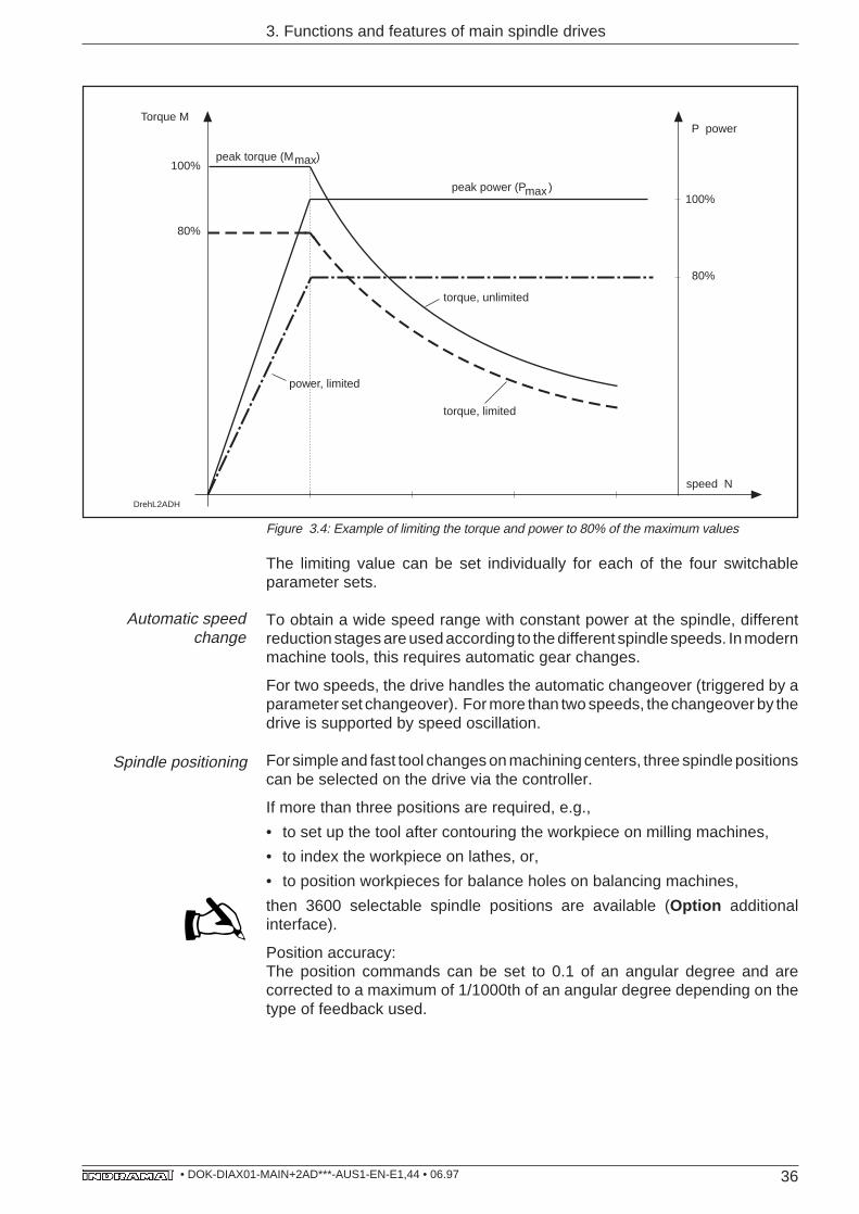
Figure 3.4: Example of limiting the torque and power to 80% of the maximum values
DrehL2ADH
peak torque (M )
Torque M
100%
80%
peak power (P )
power, limited
P power
100%
80%
torque, unlimited
speed N
torque, limited
max
max
The limiting value can be set individually for each of the four switchableparameter sets.
To obtain a wide speed range with constant power at the spindle, differentreduction stages are used according to the different spindle speeds. In modernmachine tools, this requires automatic gear changes.
For two speeds, the drive handles the automatic changeover (triggered by aparameter set changeover). For more than two speeds, the changeover by thedrive is supported by speed oscillation.
For simple and fast tool changes on machining centers, three spindle positionscan be selected on the drive via the controller.
If more than three positions are required, e.g.,
• to set up the tool after contouring the workpiece on milling machines,
• to index the workpiece on lathes, or,
• to position workpieces for balance holes on balancing machines,
then 3600 selectable spindle positions are available (Option additionalinterface).
Position accuracy:The position commands can be set to 0.1 of an angular degree and arecorrected to a maximum of 1/1000th of an angular degree depending on thetype of feedback used.
Automatic speedchange
Spindle positioning
37• DOK-DIAX01-MAIN+2AD***-AUS1-EN-E1,44 • 06.97
3. Functions and features of main spindle drives
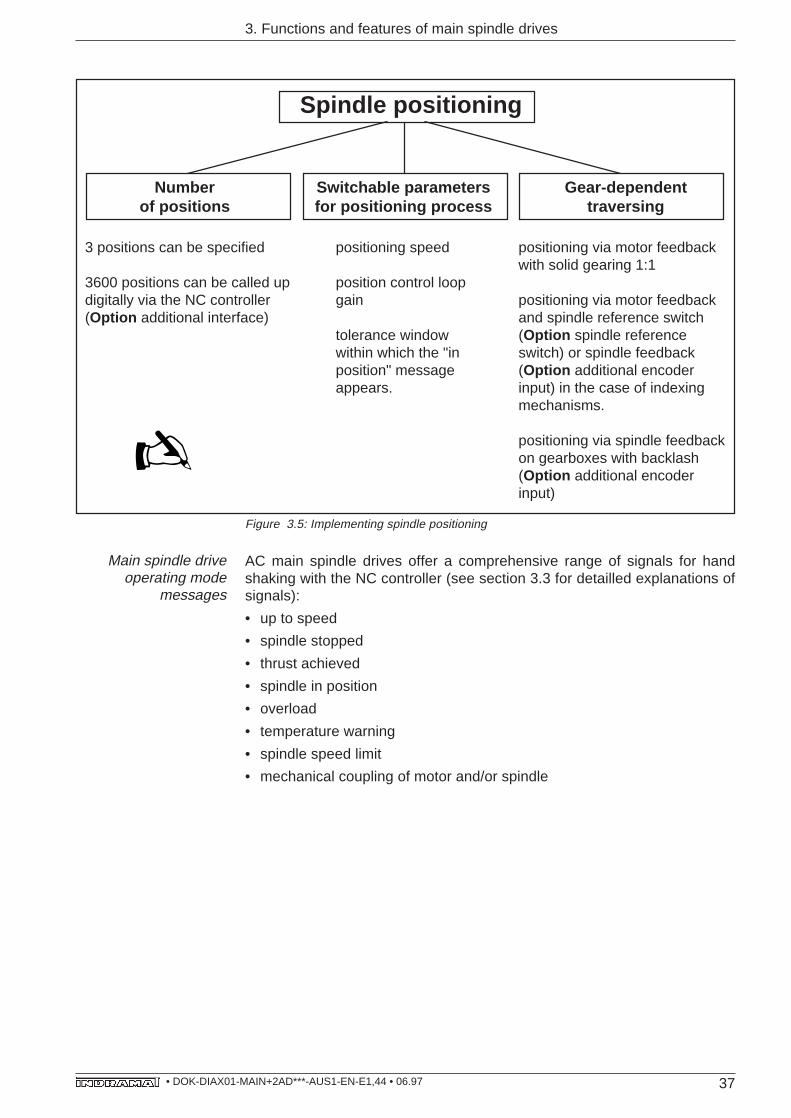
Spindle positioning
Number Switchable parameters Gear-dependentof positions for positioning process traversing
3 positions can be specified positioning speed positioning via motor feedbackwith solid gearing 1:1
3600 positions can be called up position control loopdigitally via the NC controller gain positioning via motor feedback(Option additional interface) and spindle reference switch
tolerance window (Option spindle referencewithin which the "in switch) or spindle feedbackposition" message (Option additional encoderappears. input) in the case of indexing
mechanisms.
positioning via spindle feedbackon gearboxes with backlash(Option additional encoderinput)
AC main spindle drives offer a comprehensive range of signals for handshaking with the NC controller (see section 3.3 for detailled explanations ofsignals):
• up to speed
• spindle stopped
• thrust achieved
• spindle in position
• overload
• temperature warning
• spindle speed limit
• mechanical coupling of motor and/or spindle
Main spindle driveoperating mode
messages
Figure 3.5: Implementing spindle positioning
38• DOK-DIAX01-MAIN+2AD***-AUS1-EN-E1,44 • 06.97
3. Functions and features of main spindle drives
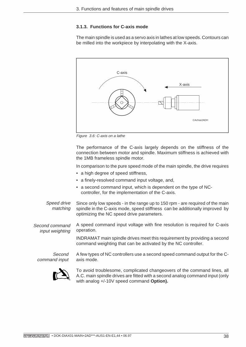
3.1.3. Functions for C-axis mode
The main spindle is used as a servo axis in lathes at low speeds. Contours canbe milled into the workpiece by interpolating with the X-axis.
Figure 3.6: C-axis on a lathe
The performance of the C-axis largely depends on the stiffness of theconnection between motor and spindle. Maximum stiffness is achieved withthe 1MB frameless spindle motor.
In comparison to the pure speed mode of the main spindle, the drive requires
• a high degree of speed stiffness,
• a finely-resolved command input voltage, and,
• a second command input, which is dependent on the type of NC-controller, for the implementation of the C-axis.
Since only low speeds - in the range up to 150 rpm - are required of the mainspindle in the C-axis mode, speed stiffness can be additionally improved byoptimizing the NC speed drive parameters.
A speed command input voltage with fine resolution is required for C-axisoperation.
INDRAMAT main spindle drives meet this requirement by providing a secondcommand weighting that can be activated by the NC controller.
A few types of NC controllers use a second speed command output for the C-axis mode.
To avoid troublesome, complicated changeovers of the command lines, allA.C. main spindle drives are fitted with a second analog command input (onlywith analog +/-10V speed command Option).
Speed drivematching
CAchse2ADH
C-axis
X-axis
Second commandinput weighting
Secondcommand input
39• DOK-DIAX01-MAIN+2AD***-AUS1-EN-E1,44 • 06.97
3. Functions and features of main spindle drives
In order to obtain uniform rotary movement in the drive at slow speeds, a speeddetector which allows sufficiently accurate speed control is needed on thedrive .
INDRAMAT main spindle drives are standardly equipped with a high-resolutionmotor feedback unit. The speed commands are adjusted with high-resolutionaccuracy at 1/2 000 000th of a revolution.
Since the C-axis involves an interpolating axis, the information about theactual-position must be continuously available to the NC controller. Thisusually involves a high-resolution measuring system with 360 000 incrementsper revolution.
INDRAMAT main spindle drives can be fitted with an interface which outputsposition data in the same way as an incremental encoder. This position datais supplied by INDRAMAT'S high-resolution spindle feedback unit (Optionadditional encoder input) or the high-resolution motor feedback on the 2ADmotor (standard).
The incremental encoder output (Option additional interface) operates asdoes a conventional incremental encoder. In this case, however, with the useof switchable parameter sets, the number of lines can be set via parametervalues and selected during operation.
The incremental encoder output transmits 360 000 increments to the drive inC-axis mode up to 150 rpm.
AC main spindle drives offer a comprehensive range of signals for handshaking with the NC controller (see section 3.3 for detailled explanation ofmessages):
• thrust achieved
• overload
• temperature warning
High-resolution motorfeedback evaluation
Incremental encoderoutput
C-axis operatingmode signals
40• DOK-DIAX01-MAIN+2AD***-AUS1-EN-E1,44 • 06.97
3. Functions and features of main spindle drives
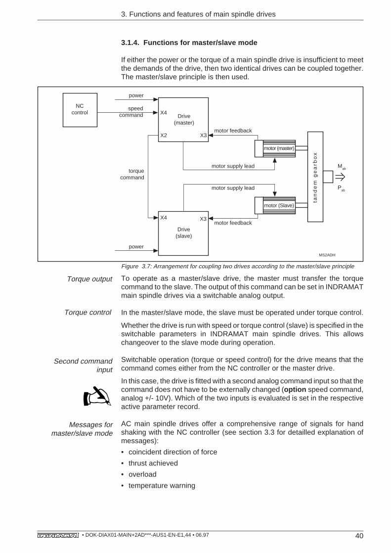
3.1.4. Functions for master/slave mode
If either the power or the torque of a main spindle drive is insufficient to meetthe demands of the drive, then two identical drives can be coupled together.The master/slave principle is then used.
MS2ADH
motor (Slave)
motor (master)
NCcontrol
speed command X4
X2 X3
Drive(master)
X4 X3
Drive(slave)
power
power
motor supply lead
motor supply lead
Mab
Pab
motor feedback
motor feedback
torquecommand
tan
de
m g
ea
rbo
x
Figure 3.7: Arrangement for coupling two drives according to the master/slave principle
To operate as a master/slave drive, the master must transfer the torquecommand to the slave. The output of this command can be set in INDRAMATmain spindle drives via a switchable analog output.
In the master/slave mode, the slave must be operated under torque control.
Whether the drive is run with speed or torque control (slave) is specified in theswitchable parameters in INDRAMAT main spindle drives. This allowschangeover to the slave mode during operation.
Switchable operation (torque or speed control) for the drive means that thecommand comes either from the NC controller or the master drive.
In this case, the drive is fitted with a second analog command input so that thecommand does not have to be externally changed (option speed command,analog +/- 10V). Which of the two inputs is evaluated is set in the respectiveactive parameter record.
AC main spindle drives offer a comprehensive range of signals for handshaking with the NC controller (see section 3.3 for detailled explanation ofmessages):
• coincident direction of force
• thrust achieved
• overload
• temperature warning
Torque output
Torque control
Second commandinput
Messages formaster/slave mode
41• DOK-DIAX01-MAIN+2AD***-AUS1-EN-E1,44 • 06.97
3.2. Functions independent of the operating mode
In addition to mode-specific functions, INDRAMAT main spindle drives offerotherr functions that are active or valid in all operating modes.
3.2.1. Speed command
The speed command can be transmitted by the NC controller to the control unitin three different ways (Option speed command)
• analog, +/- 10 V maximum
• digital, 16-bit parallel
• SERCOS interface
A feature of the three types of speed command input is the very wide speedrange from a minimum speed of 0.005 rpm up to maximum speed.
Analog, +/- 10 V maximumThis interface is fitted with two differential inputs which can be selected duringoperation.
Digital, 16-bit parallelGuarantees high command accuracy for low-value commands and longtransmission paths.
SERCOS interfaceThe fiber-optic SERCOS interface offers the most efficient type of commandinput apart from the command (position, speed or torque command). It alsotransmits the drive's actual values and diagnostic signals.
3.2.2. Direct mains connection (for RAC)
The RAC main spindle drives are designed for direct connection to groundedthree-phase mains supply systems. They are fitted with a built-in mainscontactor that is actuated by the NC controller via potential-free contacts. Noother series switching devices are required if the mains voltage is in the 3 x AC380 to 460 V; 50/60 Hz range (Option mains supply requirements).
Direct connection is possible in ungrounded three-phase mains systems, ifexcessive overvoltages are only transient and are of a low energy content(static charges, voltage increases due to lightning, etc.). In this case, however,the RAC must be protected by surge arresters (Option mains supplyrequirements).
3.2.3. Emergency-stop (E-stop) / mains off function
The E-stop shut-down circuit is built into the RAC drive and requires noadditional circuitry for the shut-down logic.
Furthermore, energy released during braking is fed back into the mainssystem.
3. Functions and features of main spindle drives
Emergency-stopshutdown circuit
(for RAC)
42• DOK-DIAX01-MAIN+2AD***-AUS1-EN-E1,44 • 06.97
3. Functions and features of main spindle drives
There are two facilities for stopping the drive in an E-stop situation:
• Internal disconnection of speed command, with power disconnect aftermotor has stopped. This is controller input activated.
• The NC controller externalls sets the speed command to zero and disconnectsthe power when the motor has stopped.
The RAC drive can brake the main spindle motor in this case as well to preventthe main spindle from coasting during a mains failure. The RAC must beequipped with the option "additional bleeder" for this purpose.
The braking method implemented can correspond to the circumstances:
• Internal speed command zeroing; braking at maximum torque.
• Internal speed command ramp; braking depends on slope of ramp.
• NC-controlled braking via speed command; braking depends on technologicalprocess (e.g., separation of workpiece from tool in gear-cutting machines).
In addition to the main spindle drive with KDA or TDA, the modular constructionof the drive package also enables servo drives to be connected to the samepower supply.
Modular drive system requirements:
• Stopping the servo drives has priority over stopping the main drive.
• The total power regenerated by the drives during braking must not exceedthe regenerated power of the supply unit, otherwise the voltage in the D.C.bus rises to inadmissible levels.
• If the D.C. bus voltage reaches the permissible limit as a result of the powerregenerated when the drives are braking, then the main spindle driveinterrupts the braking of the main spindle motors. If voltage drops again, themain spindle drive returns to braking mode.
Mains off functions (forRAC)
Emergency-stop/mains off functions
(for TDA/KDA)
43• DOK-DIAX01-MAIN+2AD***-AUS1-EN-E1,44 • 06.97
3. Functions and features of main spindle drives
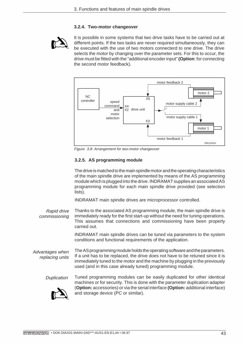
3.2.4. Two-motor changeover
It is possible in some systems that two drive tasks have to be carried out atdifferent points. If the two tasks are never required simultaneously, they canbe executed with the use of two motors connecterd to one drive. The driveselects the motor by changing over the parameter sets. For this to occur, thedrive must be fitted with the "additional encoder input" (Option : for connectingthe second motor feedback).
Figure 3.8: Arrangement for two-motor changeover
2MU2ADH
X5
X3
NCcontroller speed
commandand
motorselection
drive unit
motor 1
motor feedback 2
X4X2
motor feedback 1
motor 2
motor supply cable 2
motor supply cable 1
3.2.5. AS programming module
The drive is matched to the main spindle motor and the operating characteristicsof the main spindle drive are implemented by means of the AS programmingmodule which is plugged into the drive. INDRAMAT supplies an associated ASprogramming module for each main spindle drive provided (see selectionlists).
INDRAMAT main spindle drives are microprocessor controlled.
Thanks to the associated AS programming module, the main spindle drive isimmediately ready for the first start-up without the need for tuning operations.This assumes that connections and commissioning have been properlycarried out.
INDRAMAT main spindle drives can be tuned via parameters to the systemconditions and functional requirements of the application.
The AS programming module holds the operating software and the parameters.If a unit has to be replaced, the drive does not have to be retuned since it isimmediately tuned to the motor and the machine by plugging in the previouslyused (and in this case already tuned) programming module.
Tuned programming modules can be easily duplicated for other identicalmachines or for security. This is done with the parameter duplication adapter(Option: accessories) or via the serial interface (Option: additional interface)and storage device (PC or similar).
Rapid drivecommissioning
Advantages whenreplacing units
Duplication
44• DOK-DIAX01-MAIN+2AD***-AUS1-EN-E1,44 • 06.97
3. Functions and features of main spindle drives
3.3. Messages / Signals
When actual speed value reaches command value, the main spindle drivesignals "Nact = Nset" to the NC controller to enable the feed.
Changes of speed and actuation of the holding brake may only be executedby the NC controller at low speeds or with the spindle stationary. Below aselectable motor speed, the main spindle drive informs the controller that thespindle has stopped.
If the drive has reached 90% of its maximum loading during machining cycles(90% of M
max or P
max), the main spindle drive signals "overload" to the NC
controller. This allows speed reductions at the spindle feed to be reliablyavoided by reducing the feed.
Tools run the risk of damage due to unduly high machining forces. There areadjustable load thresholds in the main spindle drive above which "thrustachieved" is signalled to the NC controller. The drive can then prevent damageto tools by reducing the feed.
In master/slave mode, both drives must derive their force from a commonshaft. The direction of force of the slave drive must be identical to that of themaster drive. If not, the controller is informed of this by the overload message.This makes commissioning simpler and safer.
Due to the overload capacity of the main spindle motors, load cycles can beimplemented in considerably more than the continuous power briefly demandedby the motor. Correct drive dimensioning ensures that the temperature of themotor and drive is always within the permissible temperature range. If,however, the cooling system of the motor or drive, for example, is not workingcorrectly (contamination or similar), the drive runs the risk of being damagedby overheating.
INDRAMAT main spindle drives are protected against overheating.
If the temperature of the motor or drive approaches the limit of the permissibletemperature range, the drive generates "temperature warning" via a signaloutput.
If the motor temperature increases further, on reaching the maximumpermissible windings temperature the drive shuts down automatically. Thesame happens if the heatsink temperature of the drive continues to climb.
In machine tools, different tools or chucks can be used at different maximumspeeds on the main spindle during operation.
Adjustable speed thresholds, to which the speed of the spindle is then limited,can be activated in the main spindle drive.
With INDRAMAT main spindle drives the spindle speeds can be limited toseven different maximum speeds, and monitored.
Speed reachesspindle hold
Spindle stopped
Overload
Thrust achieved
Direction of force iscoincident
Temperature warning
Spindle speed limit
45• DOK-DIAX01-MAIN+2AD***-AUS1-EN-E1,44 • 06.97
3. Functions and features of main spindle drives
The spindle monitor detects a faulty, dangerous condition the first time themachine is started up, if this is caused by a malfunction in the mechanicaltransmission elements.
The drive detects any break in the mechanical link from the motor to the spindlefeedback by monitoring spindle speed.
Spindle monitoring requires a spindle feedback unit to be connected to thedrive. The drive must be fitted with an additional encoder input (Option ) forthis.
After initiating spindle positioning via the main spindle drive, the controllermust be informed when the end position is reached in order to execute furtherprogram steps.
Once the spindle has reached the end position, then the control unit signals"spindle in position" to the NC controller. The message appears with a fully-adjustable tolerance window. One tolerance window is available in each of thefour switchable parameter sets.
After the machine is switched on, the drive can only execute a program if it isguaranteed that all connected drives can process all commands . In INDRAMATmain spindle drives this is communicated to the controller by means of apotential-free contact and via a signal output.
INDRAMAT main spindle drives have two analog outputs: one is bipolar (-10V .... +10 V), the other is unipolar (0 ... +10 V).
To make commissioning easier, the drives transmit status variables such asmotor speed (command and actual-value), spindle speed, torque command,spindle position, as well as D.C. bus voltage, current and power, and analogvoltage -10 V ... +10 V.
Whilst the machine is running, the bipolar analog output can be permanentlyassigned via parameters in terms of speed and torque command, power ortemperature output. The unipolar analog output continuously supplies drivecapacity in the range of +10 V to a display instrument .
Spindle monitor
Spindle in position
"Ready"
Analog outputs
46• DOK-DIAX01-MAIN+2AD***-AUS1-EN-E1,44 • 06.97
VerlustleistungAirflow
3. Functions and features of main spindle drives
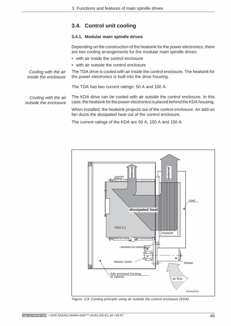
3.4. Control unit cooling
3.4.1. Modular main spindle drives
Depending on the construction of the heatsink for the power electronics, thereare two cooling arrangements for the modular main spindle drives:
• with air inside the control enclosure
• with air outside the control enclosure
The TDA drive is cooled with air inside the control enclosure. The heatsink forthe power electronics is built into the drive housing.
The TDA has two current ratings: 50 A and 100 A.
The KDA drive can be cooled with air outside the control enclosure. In thiscase, the heatsink for the power electronics is placed behind the KDA housing.
When installed, the heatsink projects out of the control enclosure. An add-onfan ducts the dissipated heat out of the control enclosure.
The current ratings of the KDA are 50 A, 100 A and 150 A.
fully enclosed housingor cabinet
heatsink
dissipated heat
cowl
exte
rnal
inte
rnal
KKDA2ADH
blower motor
air flow
blower
KDA 3.2
Figure 3.9: Cooling principle using air outside the control enclosure (KDA)
Cooling with the airinside the enclosure
Cooling with the airoutside the enclosure
47• DOK-DIAX01-MAIN+2AD***-AUS1-EN-E1,44 • 06.97
3. Functions and features of main spindle drives
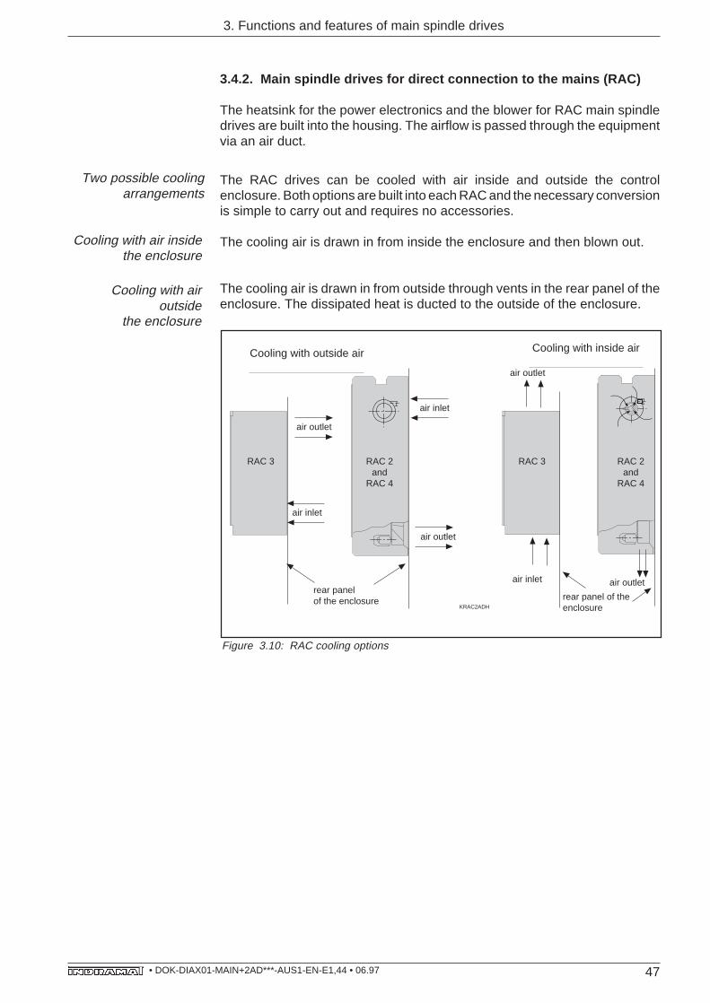
3.4.2. Main spindle drives for direct connection to the mains (RAC)
The heatsink for the power electronics and the blower for RAC main spindledrives are built into the housing. The airflow is passed through the equipmentvia an air duct.
The RAC drives can be cooled with air inside and outside the controlenclosure. Both options are built into each RAC and the necessary conversionis simple to carry out and requires no accessories.
The cooling air is drawn in from inside the enclosure and then blown out.
The cooling air is drawn in from outside through vents in the rear panel of theenclosure. The dissipated heat is ducted to the outside of the enclosure.
Figure 3.10: RAC cooling options
KRAC2ADH
Cooling with outside air
Lufteintritt
air inlet
air outlet
air outlet
rear panelof the enclosure
air inlet
air outlet
rear panel of the enclosure
air inlet
air outlet
Cooling with inside air
RAC 3 RAC 2and
RAC 4
RAC 3 RAC 2and
RAC 4
Two possible coolingarrangements
Cooling with air insidethe enclosure
Cooling with airoutside
the enclosure
48• DOK-DIAX01-MAIN+2AD***-AUS1-EN-E1,44 • 06.97
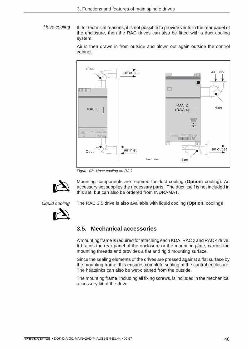
If, for technical reasons, it is not possible to provide vents in the rear panel ofthe enclosure, then the RAC drives can also be fitted with a duct coolingsystem.
Air is then drawn in from outside and blown out again outside the controlcabinet.
Hose cooling
X 6
AC-MAINSPINDLE DRIVE RAC 2
L -
L +
X 4
X 2 X 3
X 5X 1 3
Prog. Modul AS nicht unter Spannung wechseln
ASSWITCH OFF VOLTAGE BEFORE
CHANGING MODULE AS
air inlet
SRAC2ADH
AC-MAINSPINDLE DRIVE RAC 3
X 4
X 2Prog. Modul AS nicht unter Spannung wechseln
X 3
X 5X 1 3AS
SWITCH OFF VOLTAGE BEFORECHANGING MODULE AS
air inlet
air outlet
RAC 3RAC 2
(RAC 4)
Duct
duct
duct
air outlet
duct
X 14
220 VSteuerspannung
Aux. VoltageNetz/Mains
L 3L 2L 1LN
Motor
A 3A 1 A 2
DANGER HIGH VOLTAGEDISCHARGE TIMEEntladezeit 1Min.
Figure 42: Hose cooling an RAC
Mounting components are required for duct cooling (Option: cooling). Anaccessory set supplies the necessary parts. The duct itself is not included inthis set, but can also be ordered from INDRAMAT.
The RAC 3.5 drive is also available with liquid cooling (Option : cooling)!
3.5. Mechanical accessories
A mounting frame is required for attaching each KDA, RAC 2 and RAC 4 drive.It braces the rear panel of the enclosure or the mounting plate, carries themounting threads and provides a flat and rigid mounting surface.
Since the sealing elements of the drives are pressed against a flat surface bythe mounting frame, this ensures complete sealing of the control enclosure.The heatsinks can also be wet-cleaned from the outside.
The mounting frame, including all fixing screws, is included in the mechanicalaccessory kit of the drive.
3. Functions and features of main spindle drives
Liquid cooling
49• DOK-DIAX01-MAIN+2AD***-AUS1-EN-E1,44 • 06.97
4. Motor options
4. 2AD main spindle motor options
The main spindle motor options are dealt with only briefly here. A detailleddescription is given in the associated motor documentation. Each of the statedOptions requires a decision that should be written down in the selectionrecord.
4.1. MountingThe 2AD main spindle motors can be either flange or flange and foot mounted.
4.2. Power connectionBoth the position and the outlet orientation of the power connection can beselected to accommodate varying installation conditions.
4.3. Cooling methodsINDRAMAT main spindle motors have surface cooling. They are available ina slim form with an axial or radial fan fitted to the non-drive end.
With axial fan cooling, the airflow is blown from the non-drive to the drive endof the motor or drawn in from the opposite direction.
With radial fan cooling, the airflow direction is always from the non-drive to thedrive end.
4.4. Holding brakeOnce the power to the motor is switched off, the spindle can be clamped by theholding brake for a chuck or tool change.
Choose the "electrically-operated" version for main spindle applications.
Motors with electrically-released holding brakes are available for specialapplications (e.g., servo)!
4.5. Output shaftBecause of the drive's improved smooth run and the backlash-free connectionbetween the shaft and hub, the coupling of the output components (pulley,clutch, pinion) should best be a friction-locked shaft/hub connection. Themotors are constructed with cylindrical, smooth shafts for this purpose.
If for installation reasons no friction-locked shaft/hub connection is possible,then the motors can be equipped with keys.
4.6. Shaft sealing ringOil can reach the ouput shaft where the motor is flange-mounted to oil-bathgearboxes. This means that there is the risk of oil entering the motor andinterfering with operation. The motor must be fitted with a shaft sealing ring inthis case.
50• DOK-DIAX01-MAIN+2AD***-AUS1-EN-E1,44 • 06.97
4.7. Non-drive shaft endIt is often necessary to mount an additional position actual-value encoder(absolute-value encoder) in some applications (e.g., servo).
The motors can be fitted with a second, non-drive shaft end (only available inconjunction with a radial fan) in such cases.
4.8. Shaft bearingsHigh radial loads occur at the shaft bearings in the case of belt transmissions.Heavy-duty bearings are available for such applications.
4.9. Vibration severity gradeThe main spindle motors can be supplied with various vibration severitygrades for meeting special requirements.
4. Motor options
51• DOK-DIAX01-MAIN+2AD***-AUS1-EN-E1,44 • 06.97
5. Electrical connections
The electrical connections for the entire INDRAMAT main spindle drive rangeare standardized with the aim of reducing the number of cables.
There are three categories of electrical connections for main spindle drives:
• Power connections
– connections between motor and drive,
– connections between RAC drive and three-phase mains system.
• Feedback and NC connections with the same connector pin assignment,regardless of drive or motor type.
• Drive-specific connections
– within the modular drive package (TDA, KDA),
– contacts for control circuits in the RAC drives.
All categories of connections (with the exception of drive-specific connectionsin the RAC) are available as ready-made cables. They make for easy andrapid assembly of machine and control cabinet. If only ready-made cables areused, then power or connection accessories are not needed.
Electrical connectors can also be ordered. INDRAMAT supplies all thenecessary individual parts, such as leads and other accessories, if you wishto make these up yourself.
The choice of version can be recorded in the "Record of selected electricalconnections". Peculiarities such as control cabinet bushings, intermediateterminals and couplers, etc., can be noted. Otherwise, direct connection isassumed.
Standardization
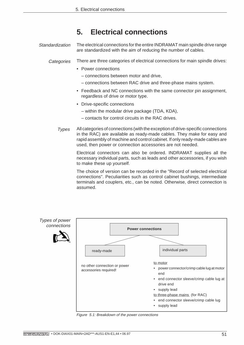
Types of powerconnections
ready-made
Figure 5.1: Breakdown of the power connections
Categories
Types
to motor• power connector/crimp cable lug at motor
end• end connector sleeve/crimp cable lug at
drive end
• supply leadto three-phase mains (for RAC)• end connector sleeve/crimp cable lug
• supply lead
individual parts
Power connections
no other connection or poweraccessories required!
5. Electrical connections
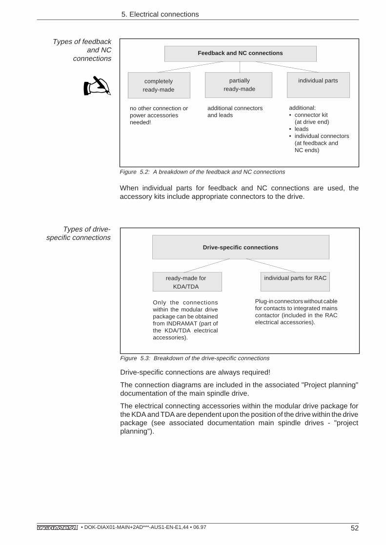
52• DOK-DIAX01-MAIN+2AD***-AUS1-EN-E1,44 • 06.97
5. Electrical connections
Types of feedbackand NC
connections
completelyready-made
individual parts
additional connectorsand leads
partiallyready-made
Feedback and NC connections
no other connection orpower accessoriesneeded!
additional:• connector kit
(at drive end)• leads• individual connectors
(at feedback andNC ends)
Figure 5.2: A breakdown of the feedback and NC connections
When individual parts for feedback and NC connections are used, theaccessory kits include appropriate connectors to the drive.
individual parts for RAC
Types of drive-specific connections
Plug-in connectors without cablefor contacts to integrated mainscontactor (included in the RACelectrical accessories).
Figure 5.3: Breakdown of the drive-specific connections
Drive-specific connections
ready-made for
KDA/TDA
Drive-specific connections are always required!
The connection diagrams are included in the associated "Project planning"documentation of the main spindle drive.
The electrical connecting accessories within the modular drive package forthe KDA and TDA are dependent upon the position of the drive within the drivepackage (see associated documentation main spindle drives - "projectplanning").
Only the connectionswithin the modular drivepackage can be obtainedfrom INDRAMAT (part ofthe KDA/TDA electricalaccessories).
53• DOK-DIAX01-MAIN+2AD***-AUS1-EN-E1,44 • 06.97
6. Selection records
6. Selection records
The selection records are used to record motor and drive options and the typesof electrical connections needed without the use of the codes.
There are three selection records:
• the main spindle drive selection record,
• the main spindle motor selection record, and,
• the electrical connections selection record
The power-related type information about the main spindle drive, programmingmodule and main spindle motor should be entered at the underlined points asper the selection list or the performance curve.
A decision is required in each block -- this should be marked with a cross. Onlyone cross per block is permitted.
The fully completed selection records are sent to INDRAMAT. These are usedto prepare a quote.
Basis for a quotation
Completion
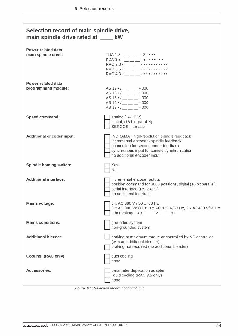
54• DOK-DIAX01-MAIN+2AD***-AUS1-EN-E1,44 • 06.97
6. Selection records
Selection record of main spindle drive,main spindle drive rated at ____ kW
Power-related datamain spindle drive: TDA 1.3 - __ __ __ - 3 - • • •
KDA 3.3 - __ __ __ - 3 - • • • - • •RAC 2.3 - __ __ __ - • • • - • • • - • •RAC 3.5 - __ __ __ - • • • - • • • - • •RAC 4.3 - __ __ __ - • • • - • • • - • •
Power-related dataprogramming module: AS 17 • / __ __ __ - 000
AS 13 • / __ __ __ - 000AS 15 • / __ __ __ - 000AS 16 • / __ __ __ - 000AS 18 • / __ __ __ - 000
Speed command: analog (+/- 10 V)digital, (16-bit -parallel)SERCOS interface
Additional encoder input: INDRAMAT high-resolution spindle feedbackincremental encoder - spindle feedbackconnection for second motor feedbacksynchronous input for spindle synchronizationno additional encoder input
Spindle homing switch: YesNo
Additional interface: incremental encoder outputposition command for 3600 positions, digital (16 bit parallel)serial interface (RS 232 C)no additional interface
Mains voltage: 3 x AC 380 V / 50 ... 60 Hz3 x AC 380 V/50 Hz, 3 x AC 415 V/50 Hz, 3 x AC460 V/60 Hzother voltage, 3 x _____ V, ____ Hz
Mains conditions: grounded systemnon-grounded system
Additional bleeder: braking at maximum torque or controlled by NC controller(with an additional bleeder)braking not required (no additional bleeder)
Cooling: (RAC only) duct coolingnone
Accessories: parameter duplication adapterliquid cooling (RAC 3.5 only)none
Figure 6.1: Selection record of control unit
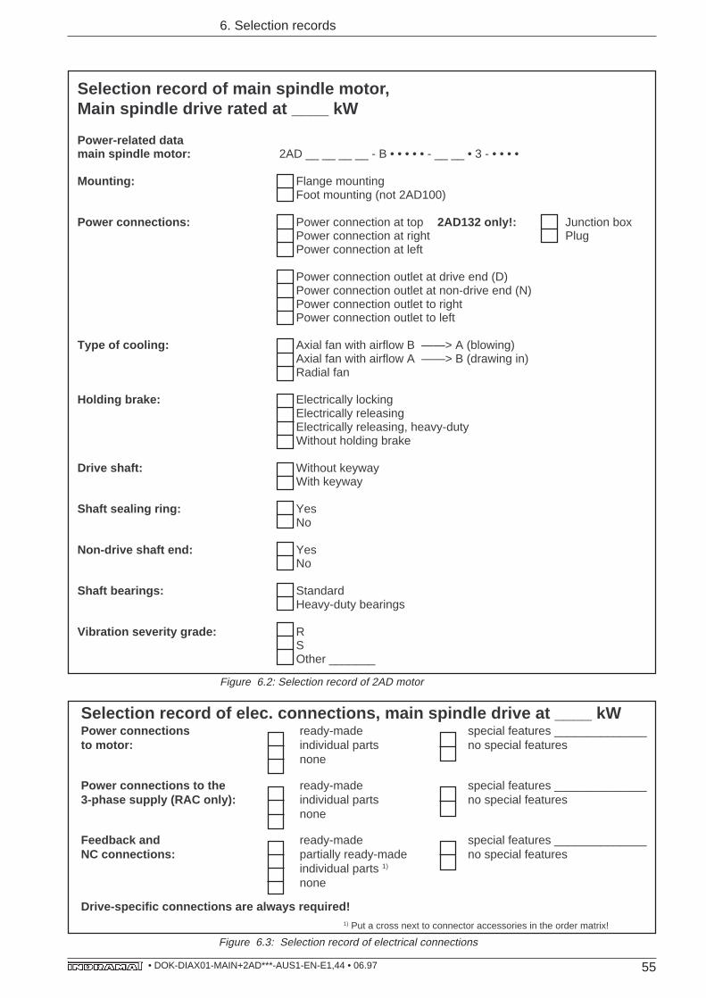
55• DOK-DIAX01-MAIN+2AD***-AUS1-EN-E1,44 • 06.97
6. Selection records
Selection record of elec. connections, main spindle drive at ____ kWPower connections ready-made special features ______________to motor: individual parts no special features
none
Power connections to the ready-made special features ______________3-phase supply (RAC only): individual parts no special features
none
Feedback and ready-made special features ______________NC connections: partially ready-made no special features
individual parts 1)
none
Drive-specific connections are always required!
Selection record of main spindle motor,Main spindle drive rated at ____ kW
Power-related datamain spindle motor: 2AD __ __ __ __ - B • • • • • - __ __ • 3 - • • • •
Mounting: Flange mountingFoot mounting (not 2AD100)
Power connections: Power connection at top 2AD132 only!: Junction boxPower connection at right PlugPower connection at left
Power connection outlet at drive end (D)Power connection outlet at non-drive end (N)Power connection outlet to rightPower connection outlet to left
Type of cooling: Axial fan with airflow B ——> A (blowing)Axial fan with airflow A ——> B (drawing in)Radial fan
Holding brake: Electrically lockingElectrically releasingElectrically releasing, heavy-dutyWithout holding brake
Drive shaft: Without keywayWith keyway
Shaft sealing ring: YesNo
Non-drive shaft end: YesNo
Shaft bearings: StandardHeavy-duty bearings
Vibration severity grade: RSOther _______
Figure 6.2: Selection record of 2AD motor
Figure 6.3: Selection record of electrical connections
1) Put a cross next to connector accessories in the order matrix!
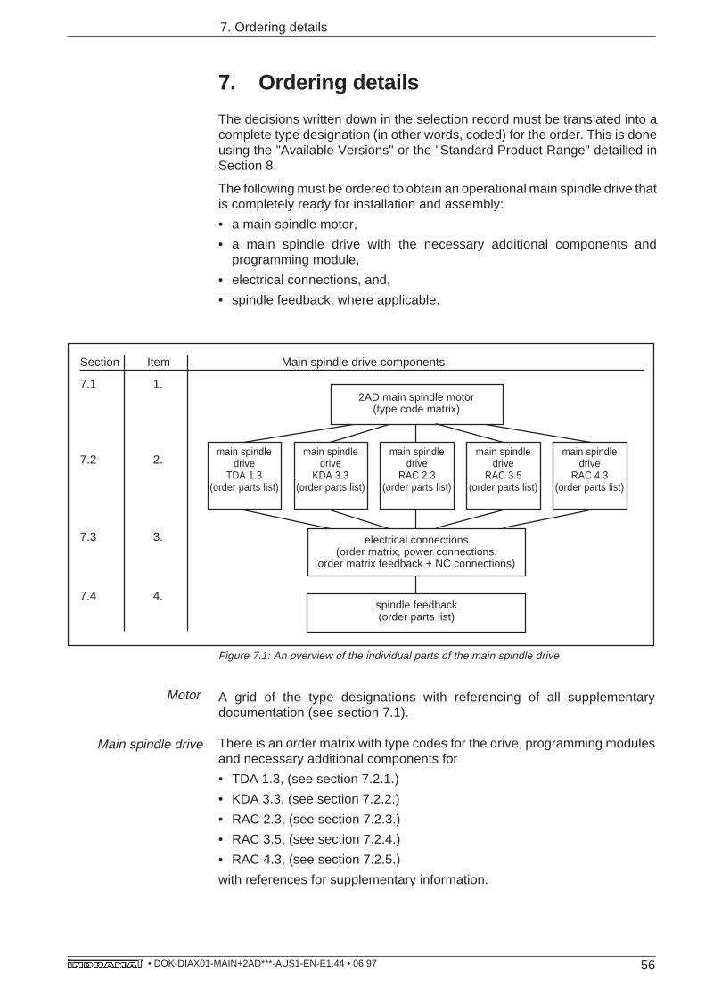
56• DOK-DIAX01-MAIN+2AD***-AUS1-EN-E1,44 • 06.97
7. Ordering details
2AD main spindle motor(type code matrix)
Figure 7.1: An overview of the individual parts of the main spindle drive
A grid of the type designations with referencing of all supplementarydocumentation (see section 7.1).
There is an order matrix with type codes for the drive, programming modulesand necessary additional components for
• TDA 1.3, (see section 7.2.1.)
• KDA 3.3, (see section 7.2.2.)
• RAC 2.3, (see section 7.2.3.)
• RAC 3.5, (see section 7.2.4.)
• RAC 4.3, (see section 7.2.5.)
with references for supplementary information.
main spindledrive
RAC 2.3(order parts list)
main spindledrive
KDA 3.3(order parts list)
main spindledrive
TDA 1.3(order parts list)
main spindledrive
RAC 3.5(order parts list)
main spindledrive
RAC 4.3(order parts list)
electrical connections(order matrix, power connections,
order matrix feedback + NC connections)
spindle feedback(order parts list)
Section Item Main spindle drive components
7.1 1.
7.2 2.
7.3 3.
7.4 4.
7. Ordering details
The decisions written down in the selection record must be translated into acomplete type designation (in other words, coded) for the order. This is doneusing the "Available Versions" or the "Standard Product Range" detailled inSection 8.
The following must be ordered to obtain an operational main spindle drive thatis completely ready for installation and assembly:
• a main spindle motor,
• a main spindle drive with the necessary additional components andprogramming module,
• electrical connections, and,
• spindle feedback, where applicable.
Motor
Main spindle drive
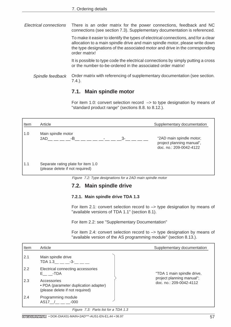
57• DOK-DIAX01-MAIN+2AD***-AUS1-EN-E1,44 • 06.97
Electrical connections
7. Ordering details
There is an order matrix for the power connections, feedback and NCconnections (see section 7.3). Supplementary documentation is referenced.
To make it easier to identify the types of electrical connections, and for a clearallocation to a main spindle drive and main spindle motor, please write downthe type designations of the associated motor and drive in the correspondingorder matrix!
It is possible to type code the electrical connections by simply putting a crossor the number-to-be-ordered in the associated order matrix!
Order matrix with referencing of supplementary documentation (see section.7.4.).
7.1. Main spindle motor
For item 1.0: convert selection record –> to type designation by means of"standard product range" (sections 8.8. to 8.12.).
Item Article Supplementary documentation
2.1 Main spindle driveTDA 1.3__ __ __-3-__ __ __
2.2 Electrical connecting accessoriesE__ __-TDA
2.3 Accessories• PDA (parameter duplication adapter)(please delete if not required)
2.4 Programming moduleAS17__/__ __ __-000
Item Article Supplementary documentation
1.0 Main spindle motor2AD__ __ __ __-B__ __ __ __ __-__ __ __3-__ __ __ __
1.1 Separate rating plate for item 1.0(please delete if not required)
“2AD main spindle motor;project planning manual”,doc. no.: 209-0042-4122
Figure 7.2: Type designations for a 2AD main spindle motor
Figure 7.3: Parts list for a TDA 1.3
7.2. Main spindle drive
7.2.1. Main spindle drive TDA 1.3
For item 2.1: convert selection record to –> type designation by means of"available versions of TDA 1.1" (section 8.1).
For item 2.2: see "Supplementary Documentation"
For item 2.4: convert selection record to –> type designation by means of"available version of the AS programming module" (section 8.13.).
"TDA 1 main spindle drive,project planning manual";doc. no.: 209-0042-4112
Spindle feedback
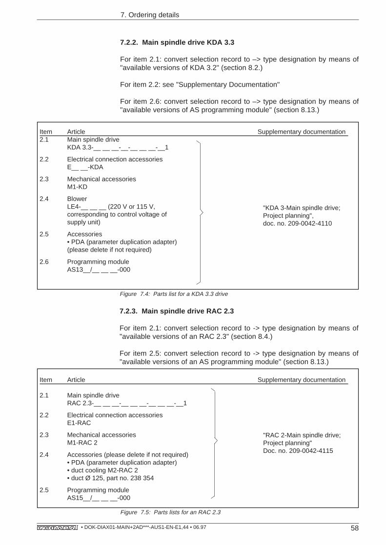
58• DOK-DIAX01-MAIN+2AD***-AUS1-EN-E1,44 • 06.97
7. Ordering details
7.2.2. Main spindle drive KDA 3.3
For item 2.1: convert selection record to –> type designation by means of"available versions of KDA 3.2" (section 8.2.)
For item 2.2: see "Supplementary Documentation"
For item 2.6: convert selection record to –> type designation by means of"available versions of AS programming module" (section 8.13.)
Figure 7.5: Parts lists for an RAC 2.3
"RAC 2-Main spindle drive;Project planning"Doc. no. 209-0042-4115
Item Article Supplementary documentation
2.1 Main spindle driveRAC 2.3-__ __ __-__ __ __-__ __ __-__1
2.2 Electrical connection accessoriesE1-RAC
2.3 Mechanical accessoriesM1-RAC 2
2.4 Accessories (please delete if not required)• PDA (parameter duplication adapter)• duct cooling M2-RAC 2• duct Ø 125, part no. 238 354
2.5 Programming moduleAS15__/__ __ __-000
Item Article Supplementary documentation2.1 Main spindle drive
KDA 3.3-__ __ __-__-__ __ __-__1
2.2 Electrical connection accessoriesE__ __-KDA
2.3 Mechanical accessoriesM1-KD
2.4 BlowerLE4-__ __ __ (220 V or 115 V,corresponding to control voltage ofsupply unit)
2.5 Accessories• PDA (parameter duplication adapter)(please delete if not required)
2.6 Programming moduleAS13__/__ __ __-000
"KDA 3-Main spindle drive;Project planning",doc. no. 209-0042-4110
Figure 7.4: Parts list for a KDA 3.3 drive
7.2.3. Main spindle drive RAC 2.3
For item 2.1: convert selection record to -> type designation by means of"available versions of an RAC 2.3" (section 8.4.)
For item 2.5: convert selection record to -> type designation by means of"available versions of an AS programming module" (section 8.13.)
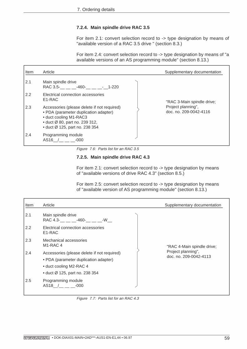
59• DOK-DIAX01-MAIN+2AD***-AUS1-EN-E1,44 • 06.97
7. Ordering details
Item Article Supplementary documentation
2.1 Main spindle driveRAC 3.5-__ __ __-460-__ __ __-__1-220
2.2 Electrical connection accessoriesE1-RAC
2.3 Accessories (please delete if not required)• PDA (parameter duplication adapter)• duct cooling M1-RAC3• duct Ø 80, part no. 239 312,• duct Ø 125, part no. 238 354
2.4 Programming moduleAS16__/__ __ __-000
Figure 7.6: Parts list for an RAC 3.5
7.2.5. Main spindle drive RAC 4.3
For item 2.1: convert selection record to -> type designation by meansof "available versions of drive RAC 4.3" (section 8.5.)
For item 2.5: convert selection record to -> type designation by meansof "available version of AS programming module" (section 8.13.)
Item Article Supplementary documentation
2.1 Main spindle driveRAC 4.3-__ __ __-460-__ __ __-W__
2.2 Electrical connection accessoriesE1-RAC
2.3 Mechanical accessoriesM1-RAC 4
2.4 Accessories (please delete if not required)
• PDA (parameter duplication adapter)
• duct cooling M2-RAC 4
• duct Ø 125, part no. 238 354
2.5 Programming moduleAS18__/__ __ __-000
Figure 7.7: Parts list for an RAC 4.3
7.2.4. Main spindle drive RAC 3.5
For item 2.1: convert selection record to -> type designation by means of"available version of a RAC 3.5 drive " (section 8.3.)
For item 2.4: convert selection record to -> type designation by means of "aavailable versions of an AS programming module" (section 8.13.)
"RAC 4-Main spindle drive;Project planning",doc. no. 209-0042-4113
"RAC 3-Main spindle drive;Project planning",doc. no. 209-0042-4116
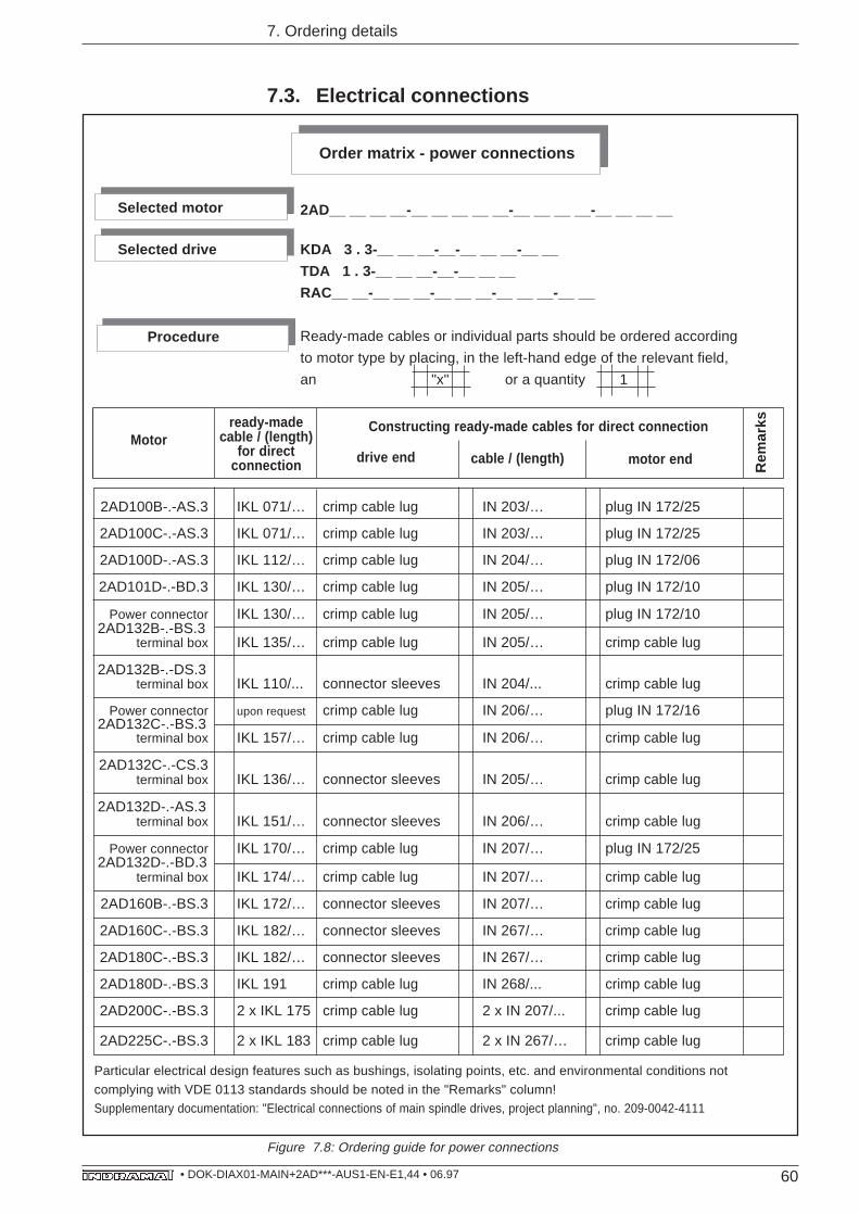
60• DOK-DIAX01-MAIN+2AD***-AUS1-EN-E1,44 • 06.97
2AD100B-.-AS.3 IKL 071/… crimp cable lug IN 203/… plug IN 172/25
2AD100C-.-AS.3 IKL 071/… crimp cable lug IN 203/… plug IN 172/25
2AD100D-.-AS.3 IKL 112/… crimp cable lug IN 204/… plug IN 172/06
2AD101D-.-BD.3 IKL 130/… crimp cable lug IN 205/… plug IN 172/10
Power connector IKL 130/… crimp cable lug IN 205/… plug IN 172/102AD132B-.-BS.3
terminal box IKL 135/… crimp cable lug IN 205/… crimp cable lug
2AD132B-.-DS.3terminal box IKL 110/... connector sleeves IN 204/... crimp cable lug
Power connector upon request crimp cable lug IN 206/… plug IN 172/162AD132C-.-BS.3
terminal box IKL 157/… crimp cable lug IN 206/… crimp cable lug
2AD132C-.-CS.3terminal box IKL 136/… connector sleeves IN 205/… crimp cable lug
2AD132D-.-AS.3terminal box IKL 151/… connector sleeves IN 206/… crimp cable lug
Power connector IKL 170/… crimp cable lug IN 207/… plug IN 172/252AD132D-.-BD.3
terminal box IKL 174/… crimp cable lug IN 207/… crimp cable lug
2AD160B-.-BS.3 IKL 172/… connector sleeves IN 207/… crimp cable lug
2AD160C-.-BS.3 IKL 182/… connector sleeves IN 267/… crimp cable lug
2AD180C-.-BS.3 IKL 182/… connector sleeves IN 267/… crimp cable lug
2AD180D-.-BS.3 IKL 191 crimp cable lug IN 268/... crimp cable lug
2AD200C-.-BS.3 2 x IKL 175 crimp cable lug 2 x IN 207/... crimp cable lug
2AD225C-.-BS.3 2 x IKL 183 crimp cable lug 2 x IN 267/… crimp cable lug
Particular electrical design features such as bushings, isolating points, etc. and environmental conditions not
complying with VDE 0113 standards should be noted in the "Remarks" column!Supplementary documentation: "Electrical connections of main spindle drives, project planning", no. 209-0042-4111
ready-madecable / (length)
for directconnection
Order matrix - power connections
2AD__ __ __ __-__ __ __ __ __-__ __ __ __-__ __ __ __
KDA 3 . 3-__ __ __-__-__ __ __-__ __
TDA 1 . 3-__ __ __-__-__ __ __
RAC__ __-__ __ __-__ __ __-__ __ __-__ __
Ready-made cables or individual parts should be ordered according
to motor type by placing, in the left-hand edge of the relevant field,
an "x" or a quantity 1
Selected motor
Selected drive
Procedure
Constructing ready-made cables for direct connection
Rem
arks
drive end cable / (length) motor endMotor
7. Ordering details
Figure 7.8: Ordering guide for power connections
7.3. Electrical connections
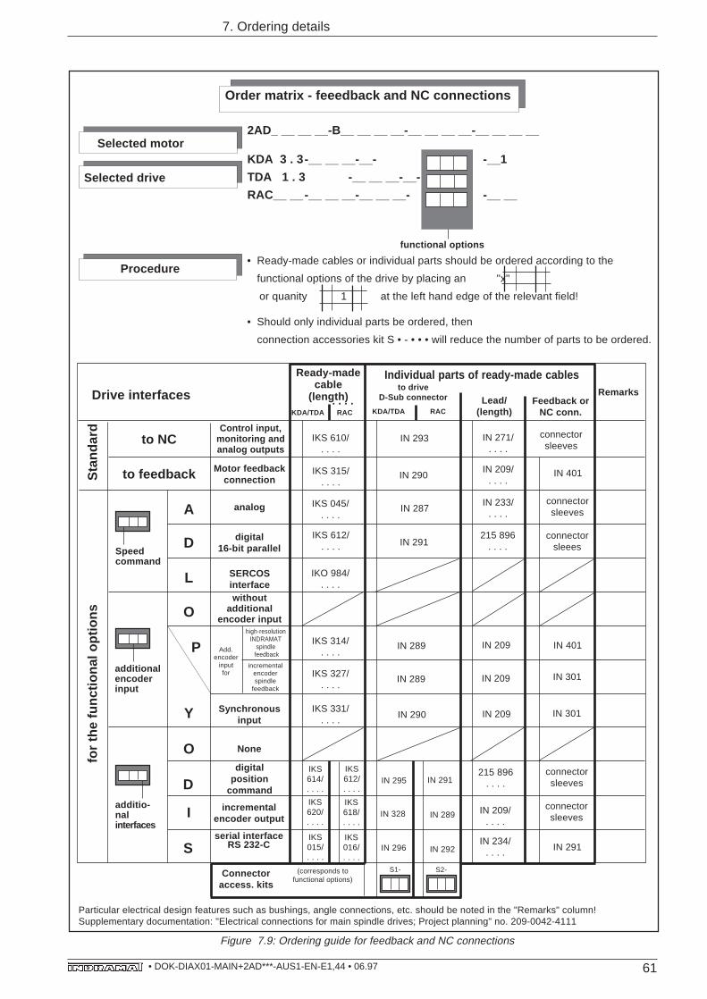
61• DOK-DIAX01-MAIN+2AD***-AUS1-EN-E1,44 • 06.97
Selected drive
Selected motor
functional options
Procedure
Particular electrical design features such as bushings, angle connections, etc. should be noted in the "Remarks" column!Supplementary documentation: "Electrical connections for main spindle drives; Project planning" no. 209-0042-4111
Drive interfaces
to NC IN 293
Individual parts of ready-made cables
Feedback orNC conn.
to feedback Motor feedbackconnection
IKS 315/. . . .
IN 290 IN 401
A analog IKS 045/. . . .
IN 287
D digital16-bit parallel
IKS 612/. . . . IN 291
L SERCOSinterface
IKO 984/. . . .
O
Add.encoder
inputfor
IKS 314/. . . .
IN 289 IN 209 IN 401Phigh-resolution
INDRAMATspindle
feedback
IKS 327/. . . .
IN 289 IN 209
incrementalencoderspindle
feedback
IN 301
Y Synchronousinput
IKS 331/. . . . IN 290 IN 209 IN 301
O None
D
IN 209/. . . .
I incrementalencoder output
SIN 234/
. . . . IN 291
withoutadditional
encoder input
Sta
ndar
d
digitalposition
command
for
the
func
tiona
l opt
ions
215 896. . . .
Speedcommand
additionalencoderinput
additio-nalinterfaces
connectorsleeves
connectorsleees
connectorsleeves
connectorsleeves
S1-
IKS620/. . . .
IKS618/. . . .
IKS015/. . . .
IKS016/. . . .
IKS614/. . . .
IKS612/. . . .
S2-
IN 289
IN 292IN 296
IN 328
IN 295 IN 291
IN 271/. . . .
IN 209/. . . .
IN 233/. . . .
215 896. . . .
Connectoraccess. kits
Remarks
connectorsleeves
serial interfaceRS 232-C
7. Ordering details
Figure 7.9: Ordering guide for feedback and NC connections
Ready-madecable
(length)to drive
D-Sub connector
(corresponds tofunctional options)
KDA/TDA RAC
IKS 610/. . . .
. . . .
Control input,monitoring andanalog outputs
KDA/TDA RAC
Lead/(length)
Order matrix - feeedback and NC connections
2AD_ __ __ __-B__ __ __ __-__ __ __ __-__ __ __ __
KDA 3 . 3-__ __ __-__- -__1
TDA 1 . 3 -__ __ __-__-
RAC__ __-__ __ __-__ __ __- -__ __
• Ready-made cables or individual parts should be ordered according to the
functional options of the drive by placing an "x"
or quanity 1 at the left hand edge of the relevant field!
• Should only individual parts be ordered, then
connection accessories kit S • - • • • will reduce the number of parts to be ordered.
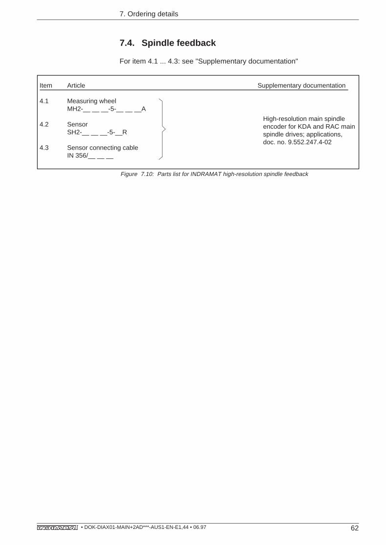
62• DOK-DIAX01-MAIN+2AD***-AUS1-EN-E1,44 • 06.97
7.4. Spindle feedback
For item 4.1 ... 4.3: see "Supplementary documentation"
Item Article Supplementary documentation
4.1 Measuring wheelMH2-__ __ __-5-__ __ __A
4.2 SensorSH2-__ __ __-5-__R
4.3 Sensor connecting cableIN 356/__ __ __
High-resolution main spindleencoder for KDA and RAC mainspindle drives; applications,doc. no. 9.552.247.4-02
Figure 7.10: Parts list for INDRAMAT high-resolution spindle feedback
7. Ordering details
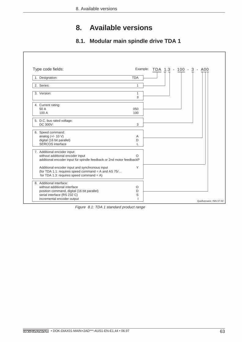
63• DOK-DIAX01-MAIN+2AD***-AUS1-EN-E1,44 • 06.97
8. Available versions
8. Available versions
8.1. Modular main spindle drive TDA 1
1. Designation: TDA
2. Series: 1
3. Version: 13
4. Current rating:50 A 050100 A 100
5. D.C. bus rated voltage:DC 300V: 3
6. Speed command:analog (+/- 10 V) Adigital (16 bit parallel) DSERCOS interface L
7. Additional encoder input:without additional encoder input Oadditional encoder input für spindle feedback or 2nd motor feedbackP
Additional encoder input and synchronous input Y(for TDA 1.1: requires speed command = A and AS 75/… for TDA 1.3: requires speed command = A)
8. Additional interface:without additional interface Oposition command, digital (16 bit parallel) Dserial interface (RS 232 C) Sincremental encoder output I
Type code fields: Example: TDA 1.3 - 100 - 3 - A00
Quellverweis: INN 07.02
Figure 8.1: TDA 1 standard product range
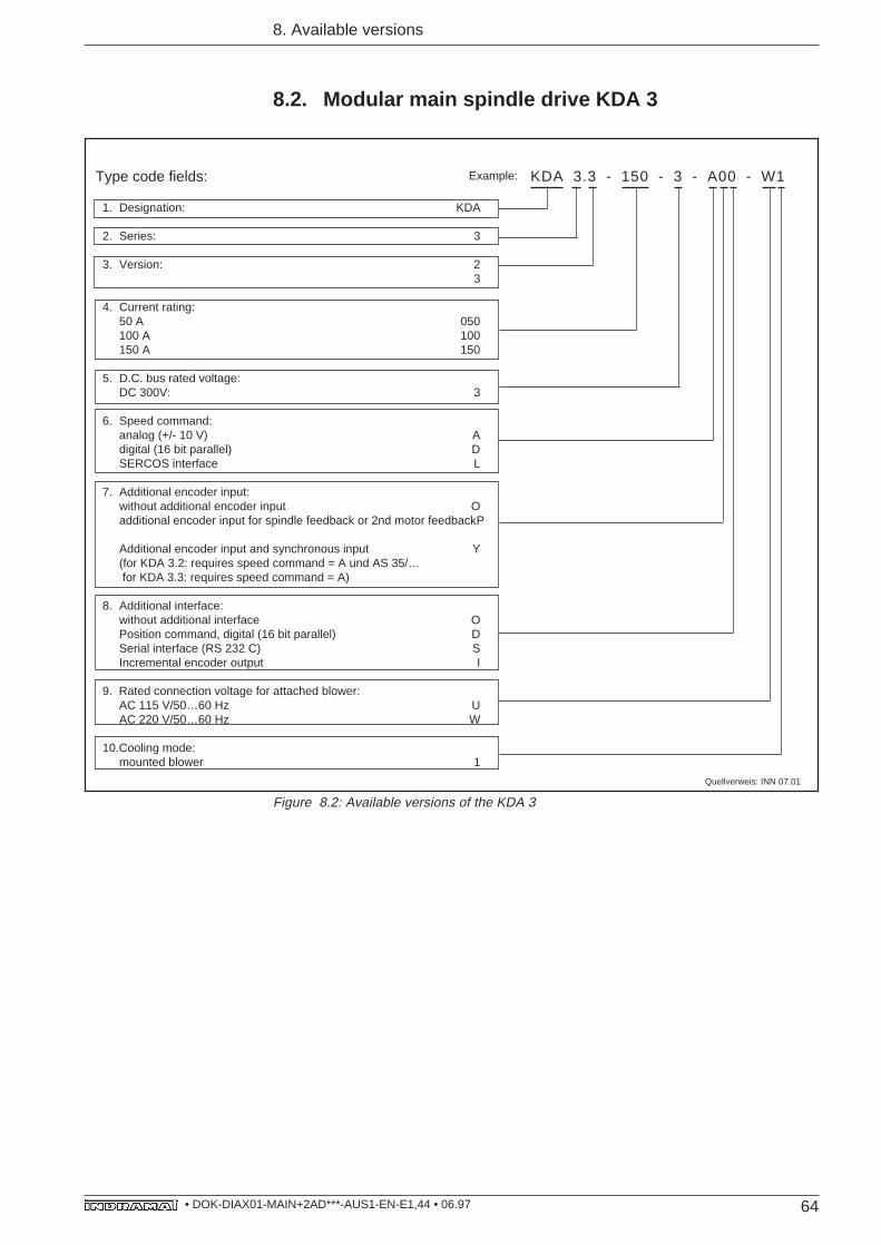
64• DOK-DIAX01-MAIN+2AD***-AUS1-EN-E1,44 • 06.97
1. Designation: KDA
2. Series: 3
3. Version: 23
4. Current rating:50 A 050100 A 100150 A 150
5. D.C. bus rated voltage:DC 300V: 3
6. Speed command:analog (+/- 10 V) Adigital (16 bit parallel) DSERCOS interface L
7. Additional encoder input:without additional encoder input Oadditional encoder input for spindle feedback or 2nd motor feedbackP
Additional encoder input and synchronous input Y(for KDA 3.2: requires speed command = A und AS 35/… for KDA 3.3: requires speed command = A)
8. Additional interface:without additional interface OPosition command, digital (16 bit parallel) DSerial interface (RS 232 C) SIncremental encoder output I
9. Rated connection voltage for attached blower:AC 115 V/50…60 Hz UAC 220 V/50…60 Hz W
10.Cooling mode:mounted blower 1
Type code fields: KDA 3.3 - 150 - 3 - A00 - W1Example:
8. Available versions
8.2. Modular main spindle drive KDA 3
Quellverweis: INN 07.01
Figure 8.2: Available versions of the KDA 3
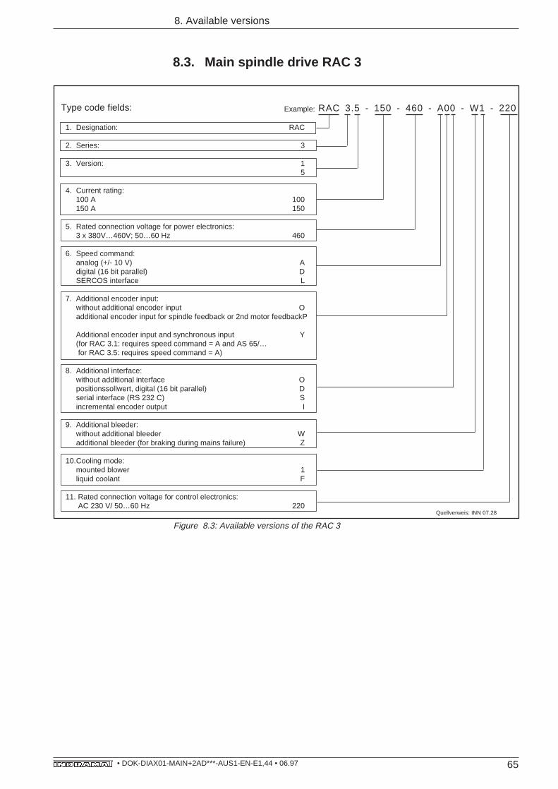
65• DOK-DIAX01-MAIN+2AD***-AUS1-EN-E1,44 • 06.97
1. Designation: RAC
2. Series: 3
3. Version: 15
4. Current rating:100 A 100150 A 150
5. Rated connection voltage for power electronics:3 x 380V…460V; 50…60 Hz 460
6. Speed command:analog (+/- 10 V) Adigital (16 bit parallel) DSERCOS interface L
7. Additional encoder input:without additional encoder input Oadditional encoder input for spindle feedback or 2nd motor feedbackP
Additional encoder input and synchronous input Y(for RAC 3.1: requires speed command = A and AS 65/… for RAC 3.5: requires speed command = A)
8. Additional interface:without additional interface Opositionssollwert, digital (16 bit parallel) Dserial interface (RS 232 C) Sincremental encoder output I
9. Additional bleeder:without additional bleeder Wadditional bleeder (for braking during mains failure) Z
10.Cooling mode:mounted blower 1liquid coolant F
11. Rated connection voltage for control electronics: AC 230 V/ 50…60 Hz 220
Type code fields: Example:
8. Available versions
8.3. Main spindle drive RAC 3
RAC 3.5 - 150 - 460 - A00 - W1 - 220
Quellverweis: INN 07.28
Figure 8.3: Available versions of the RAC 3
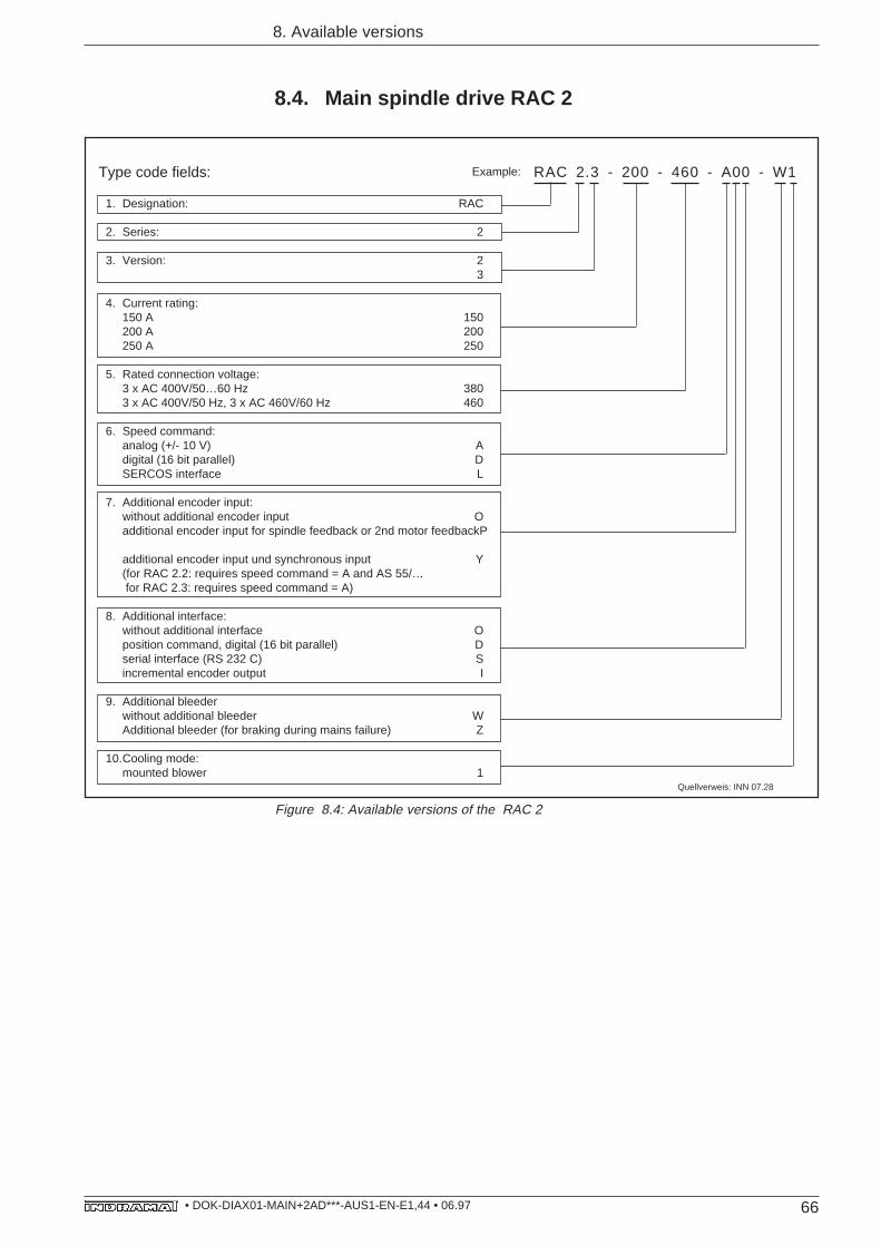
66• DOK-DIAX01-MAIN+2AD***-AUS1-EN-E1,44 • 06.97
8. Available versions
8.4. Main spindle drive RAC 2
1. Designation: RAC
2. Series: 2
3. Version: 23
4. Current rating:150 A 150200 A 200250 A 250
5. Rated connection voltage:3 x AC 400V/50…60 Hz 3803 x AC 400V/50 Hz, 3 x AC 460V/60 Hz 460
6. Speed command:analog (+/- 10 V) Adigital (16 bit parallel) DSERCOS interface L
7. Additional encoder input:without additional encoder input Oadditional encoder input for spindle feedback or 2nd motor feedbackP
additional encoder input und synchronous input Y(for RAC 2.2: requires speed command = A and AS 55/… for RAC 2.3: requires speed command = A)
8. Additional interface:without additional interface Oposition command, digital (16 bit parallel) Dserial interface (RS 232 C) Sincremental encoder output I
9. Additional bleederwithout additional bleeder WAdditional bleeder (for braking during mains failure) Z
10.Cooling mode:mounted blower 1
Type code fields: Example: RAC 2.3 - 200 - 460 - A00 - W1
Quellverweis: INN 07.28
Figure 8.4: Available versions of the RAC 2
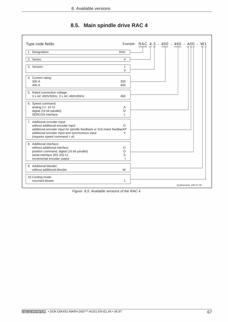
67• DOK-DIAX01-MAIN+2AD***-AUS1-EN-E1,44 • 06.97
8. Available versions
8.5. Main spindle drive RAC 4
RAC 4.3 - 400 - 460 - A00 - W1
1. Designation: RAC
2. Series: 4
3. Version: 13
4. Current rating:300 A 300400 A 400
5. Rated connection voltage:3 x AC 400V/50Hz, 3 x AC 460V/60Hz 460
6. Speed command:analog (+/- 10 V) Adigital (16 bit parallel) DSERCOS interface L
7. Additional encoder input:without additional encoder input Oadditional encoder input for spindle feedback or 2nd motor feedbackPadditional encoder input and synchronous input Y(requires speed command = A)
8. Additional interface:without additional interface Oposition command, digital (16 bit parallel) Dserial interface (RS 232 C) Sincremental encoder output I
9. Additional bleeder:without additional bleeder W
10.Cooling mode:mounted blower 1
Type code fields: Example:
Quellverweis: INN 07.28
Figure 8.5: Available versions of the RAC 4
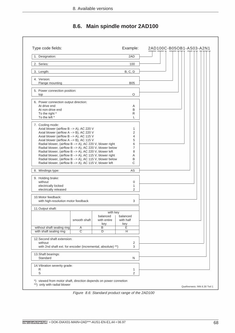
68• DOK-DIAX01-MAIN+2AD***-AUS1-EN-E1,44 • 06.97
1. Designation: 2AD
2. Series: 100
3. Length: B, C, D
4. Version:Flange mounting B05
5. Power connection position:top O
6. Power connection output direction:At drive end AAt non-drive end BTo the right * RTo the left * L
7. Cooling mode:Axial blower (airflow B --> A), AC 220 V 1Axial blower (airflow A --> B), AC 220 V 2Axial blower (airflow B --> A), AC 115 V 4Axial blower (airflow A --> B), AC 115 V 5Radial blower, (airflow B --> A), AC 220 V, blower right 6Radial blower, (airflow B --> A), AC 220 V, blower below 7Radial blower, (airflow B --> A), AC 220 V, blower left 8Radial blower, (airflow B --> A), AC 115 V, blower right ARadial blower, (airflow B --> A), AC 115 V, blower below BRadial blower, (airflow B --> A), AC 115 V, blower left C
8. Windings type: AS
9. Holding brake:without 0electrically locked 1electrically released 2
10.Motor feedback:with high-resolution motor feedback 3
11.Output shaft: with key balanced balancedsmooth shaft with entire with half key key
without shaft sealing ring A B E with shaft sealing ring C D H
12.Second shaft extension:without 2with 2nd shaft ext. for encoder (incremental, absolute) **) 3
13.Shaft bearings:Standard N
14.Vibration severity grade:R 1S 2
*) viewed from motor shaft, direction depends on power connetion**) only with radial blower
8. Available versions
8.6. Main spindle motor 2AD100
Type code fields: Example: 2AD100C-B05OB1-AS03-A2N1
Quellverweis: INN 6.30 Teil 1
Figure 8.6: Standard product range of the 2AD100
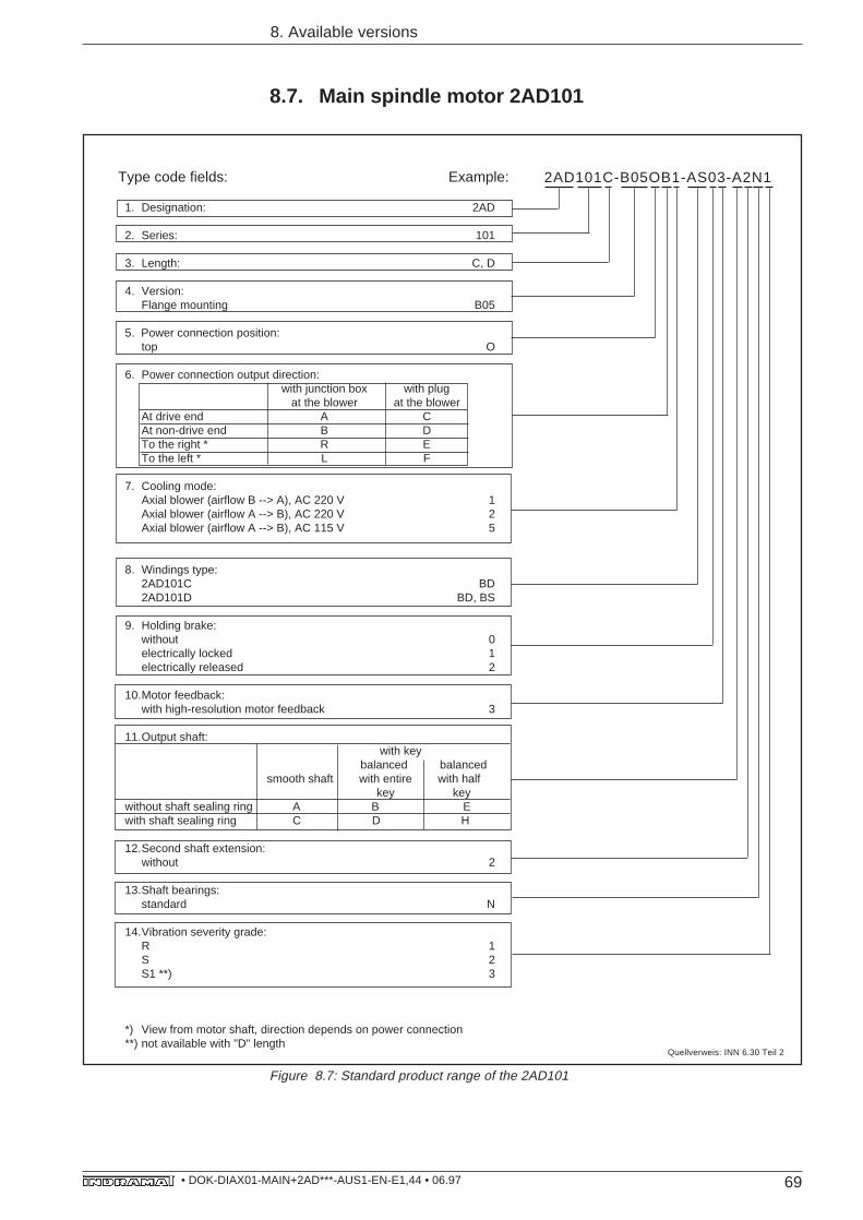
69• DOK-DIAX01-MAIN+2AD***-AUS1-EN-E1,44 • 06.97
1. Designation: 2AD
2. Series: 101
3. Length: C, D
4. Version:Flange mounting B05
5. Power connection position:top O
6. Power connection output direction:with junction box with plug
at the blower at the blowerAt drive end A CAt non-drive end B DTo the right * R ETo the left * L F
7. Cooling mode:Axial blower (airflow B --> A), AC 220 V 1Axial blower (airflow A --> B), AC 220 V 2Axial blower (airflow A --> B), AC 115 V 5
8. Windings type:2AD101C BD2AD101D BD, BS
9. Holding brake:without 0electrically locked 1electrically released 2
10.Motor feedback:with high-resolution motor feedback 3
11.Output shaft: with key balanced balancedsmooth shaft with entire with half key key
without shaft sealing ring A B Ewith shaft sealing ring C D H
12.Second shaft extension:without 2
13.Shaft bearings:standard N
14.Vibration severity grade:R 1S 2S1 **) 3
*) View from motor shaft, direction depends on power connection**) not available with "D" length
8. Available versions
8.7. Main spindle motor 2AD101
Type code fields: Example: 2AD101C-B05OB1-AS03-A2N1
Quellverweis: INN 6.30 Teil 2
Figure 8.7: Standard product range of the 2AD101
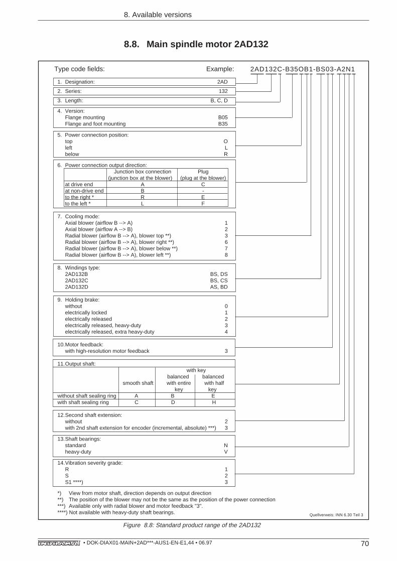
70• DOK-DIAX01-MAIN+2AD***-AUS1-EN-E1,44 • 06.97
1. Designation: 2AD
2. Series: 132
3. Length: B, C, D
4. Version:Flange mounting B05Flange and foot mounting B35
5. Power connection position:top Oleft Lbelow R
6. Power connection output direction:Junction box connection Plug
(junction box at the blower) (plug at the blower)at drive end A Cat non-drive end B -to the right * R Eto the left * L F
7. Cooling mode:Axial blower (airflow B --> A) 1Axial blower (airflow A --> B) 2Radial blower (airflow B --> A), blower top **) 3Radial blower (airflow B --> A), blower right **) 6Radial blower (airflow B --> A), blower below **) 7Radial blower (airflow B --> A), blower left **) 8
8. Windings type:2AD132B BS, DS2AD132C BS, CS2AD132D AS, BD
9. Holding brake:without 0electrically locked 1electrically released 2electrically released, heavy-duty 3electrically released, extra heavy-duty 4
10.Motor feedback:with high-resolution motor feedback 3
11.Output shaft: with key balanced balancedsmooth shaft with entire with half key key
without shaft sealing ring A B Ewith shaft sealing ring C D H
12.Second shaft extension:without 2with 2nd shaft extension for encoder (incremental, absolute) ***) 3
13.Shaft bearings:standard Nheavy-duty V
14.Vibration severity grade:R 1S 2S1 ****) 3
*) View from motor shaft, direction depends on output direction**) The position of the blower may not be the same as the position of the power connection***) Available only with radial blower and motor feedback "3".****) Not available with heavy-duty shaft bearings.
8. Available versions
8.8. Main spindle motor 2AD132
Type code fields: Example: 2AD132C-B35OB1-BS03-A2N1
Figure 8.8: Standard product range of the 2AD132
Quellverweis: INN 6.30 Teil 3
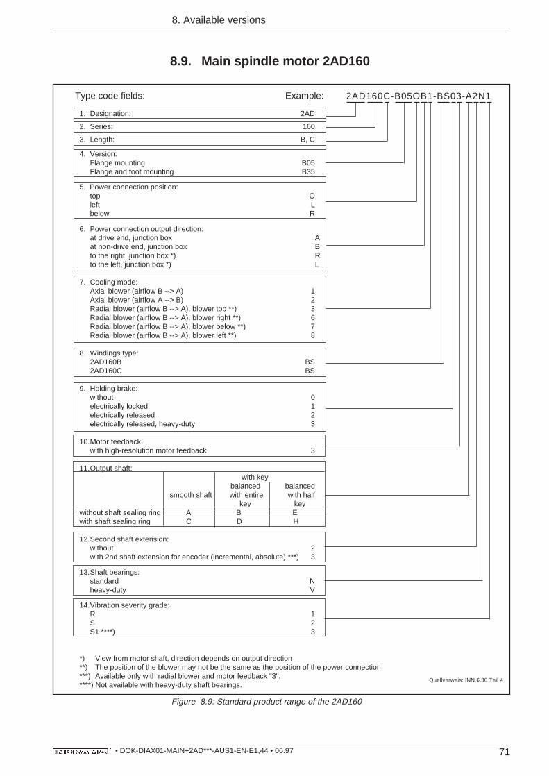
71• DOK-DIAX01-MAIN+2AD***-AUS1-EN-E1,44 • 06.97
1. Designation: 2AD
2. Series: 160
3. Length: B, C
4. Version:Flange mounting B05Flange and foot mounting B35
5. Power connection position:top Oleft Lbelow R
6. Power connection output direction:at drive end, junction box Aat non-drive end, junction box Bto the right, junction box *) Rto the left, junction box *) L
7. Cooling mode:Axial blower (airflow B --> A) 1Axial blower (airflow A --> B) 2Radial blower (airflow B --> A), blower top **) 3Radial blower (airflow B --> A), blower right **) 6Radial blower (airflow B --> A), blower below **) 7Radial blower (airflow B --> A), blower left **) 8
8. Windings type:2AD160B BS2AD160C BS
9. Holding brake:without 0electrically locked 1electrically released 2electrically released, heavy-duty 3
10.Motor feedback:with high-resolution motor feedback 3
11.Output shaft: with key
balanced balancedsmooth shaft with entire with half key key
without shaft sealing ring A B Ewith shaft sealing ring C D H
12.Second shaft extension:without 2with 2nd shaft extension for encoder (incremental, absolute) ***) 3
13.Shaft bearings:standard Nheavy-duty V
14.Vibration severity grade:R 1S 2S1 ****) 3
*) View from motor shaft, direction depends on output direction**) The position of the blower may not be the same as the position of the power connection***) Available only with radial blower and motor feedback "3".****) Not available with heavy-duty shaft bearings.
8. Available versions
8.9. Main spindle motor 2AD160
Type code fields: Example: 2AD160C-B05OB1-BS03-A2N1
Quellverweis: INN 6.30 Teil 4
Figure 8.9: Standard product range of the 2AD160
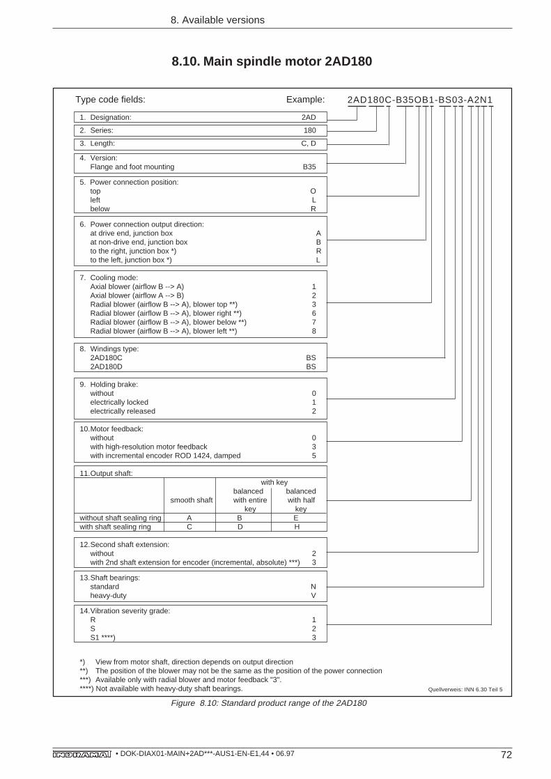
72• DOK-DIAX01-MAIN+2AD***-AUS1-EN-E1,44 • 06.97
8. Available versions
8.10. Main spindle motor 2AD180
1. Designation: 2AD
2. Series: 180
3. Length: C, D
4. Version:Flange and foot mounting B35
5. Power connection position:top Oleft Lbelow R
6. Power connection output direction:at drive end, junction box Aat non-drive end, junction box Bto the right, junction box *) Rto the left, junction box *) L
7. Cooling mode:Axial blower (airflow B --> A) 1Axial blower (airflow A --> B) 2Radial blower (airflow B --> A), blower top **) 3Radial blower (airflow B --> A), blower right **) 6Radial blower (airflow B --> A), blower below **) 7Radial blower (airflow B --> A), blower left **) 8
8. Windings type:2AD180C BS2AD180D BS
9. Holding brake:without 0electrically locked 1electrically released 2
10.Motor feedback:without 0with high-resolution motor feedback 3with incremental encoder ROD 1424, damped 5
11.Output shaft: with key
balanced balancedsmooth shaft with entire with half key key
without shaft sealing ring A B Ewith shaft sealing ring C D H
12.Second shaft extension:without 2with 2nd shaft extension for encoder (incremental, absolute) ***) 3
13.Shaft bearings:standard Nheavy-duty V
14.Vibration severity grade:R 1S 2S1 ****) 3
*) View from motor shaft, direction depends on output direction**) The position of the blower may not be the same as the position of the power connection***) Available only with radial blower and motor feedback "3".****) Not available with heavy-duty shaft bearings.
Type code fields: Example: 2AD180C-B35OB1-BS03-A2N1
Figure 8.10: Standard product range of the 2AD180
Quellverweis: INN 6.30 Teil 5
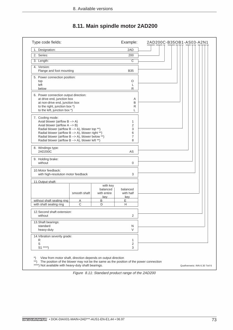
73• DOK-DIAX01-MAIN+2AD***-AUS1-EN-E1,44 • 06.97
1. Designation: 2AD
2. Series: 200
3. Length: C
4. Version:Flange and foot mounting B35
5. Power connection position:top Oleft Lbelow R
6. Power connection output direction:at drive end, junction box Aat non-drive end, junction box Bto the right, junction box *) Rto the left, junction box *) L
7. Cooling mode:Axial blower (airflow B --> A) 1Axial blower (airflow A --> B) 2Radial blower (airflow B --> A), blower top **) 3Radial blower (airflow B --> A), blower right **) 6Radial blower (airflow B --> A), blower below **) 7Radial blower (airflow B --> A), blower left **) 8
8. Windings type:2AD200C AS
9. Holding brake:without 0
10.Motor feedback:with high-resolution motor feedback 3
11.Output shaft: with key
balanced balancedsmooth shaft with entire with half key key
without shaft sealing ring A B Ewith shaft sealing ring C D H
12.Second shaft extension:without 2
13.Shaft bearings:standard Nheavy-duty V
14.Vibration severity grade:R 1S 2S1 ****) 3
*) View from motor shaft, direction depends on output direction**) The position of the blower may not be the same as the position of the power connection****) Not available with heavy-duty shaft bearings.
8. Available versions
8.11. Main spindle motor 2AD200
Type code fields: Example: 2AD200C-B35OB1-AS03-A2N1
Quellverweis: INN 6.30 Teil 6
Figure 8.11: Standard product range of the 2AD200
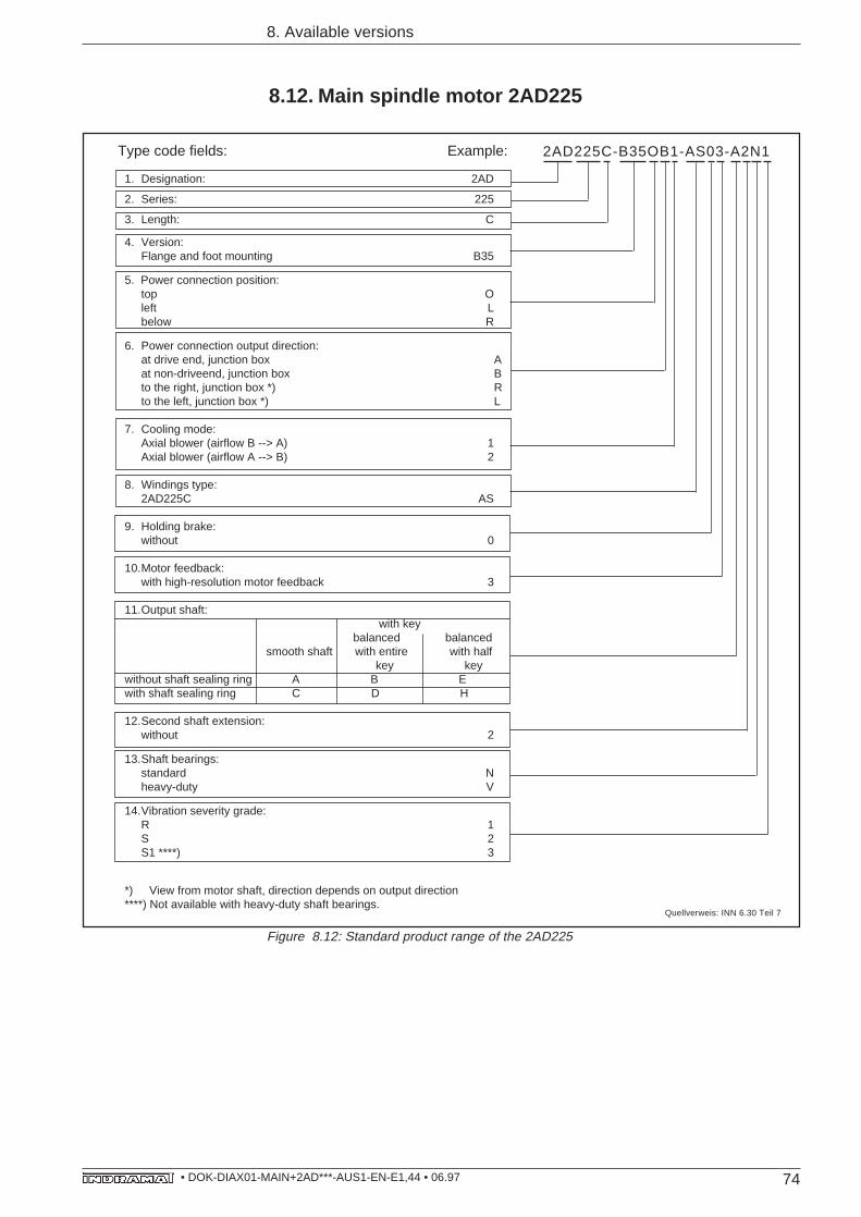
74• DOK-DIAX01-MAIN+2AD***-AUS1-EN-E1,44 • 06.97
1. Designation: 2AD
2. Series: 225
3. Length: C
4. Version:Flange and foot mounting B35
5. Power connection position:top Oleft Lbelow R
6. Power connection output direction:at drive end, junction box Aat non-driveend, junction box Bto the right, junction box *) Rto the left, junction box *) L
7. Cooling mode:Axial blower (airflow B --> A) 1Axial blower (airflow A --> B) 2
8. Windings type:2AD225C AS
9. Holding brake:without 0
10.Motor feedback:with high-resolution motor feedback 3
11.Output shaft: with key balanced balancedsmooth shaft with entire with half key key
without shaft sealing ring A B Ewith shaft sealing ring C D H
12.Second shaft extension:without 2
13.Shaft bearings:standard Nheavy-duty V
14.Vibration severity grade:R 1S 2S1 ****) 3
*) View from motor shaft, direction depends on output direction****) Not available with heavy-duty shaft bearings.
8.12. Main spindle motor 2AD225
8. Available versions
Type code fields: Example: 2AD225C-B35OB1-AS03-A2N1
Quellverweis: INN 6.30 Teil 7
Figure 8.12: Standard product range of the 2AD225
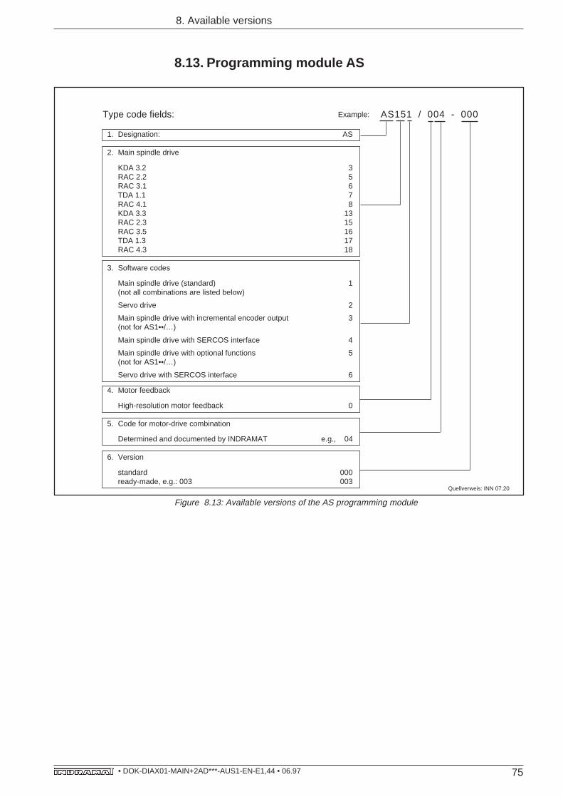
75• DOK-DIAX01-MAIN+2AD***-AUS1-EN-E1,44 • 06.97
8.13. Programming module AS
8. Available versions
1. Designation: AS
2. Main spindle drive
KDA 3.2 3RAC 2.2 5RAC 3.1 6TDA 1.1 7RAC 4.1 8KDA 3.3 13RAC 2.3 15RAC 3.5 16TDA 1.3 17RAC 4.3 18
3. Software codes
Main spindle drive (standard) 1(not all combinations are listed below)
Servo drive 2
Main spindle drive with incremental encoder output 3(not for AS1••/…)
Main spindle drive with SERCOS interface 4
Main spindle drive with optional functions 5(not for AS1••/…)
Servo drive with SERCOS interface 6
4. Motor feedback
High-resolution motor feedback 0
5. Code for motor-drive combination
Determined and documented by INDRAMAT e.g., 04
6. Version
standard 000ready-made, e.g.: 003 003
Type code fields: AS151 / 004 - 000Example:
Figure 8.13: Available versions of the AS programming module
Quellverweis: INN 07.20
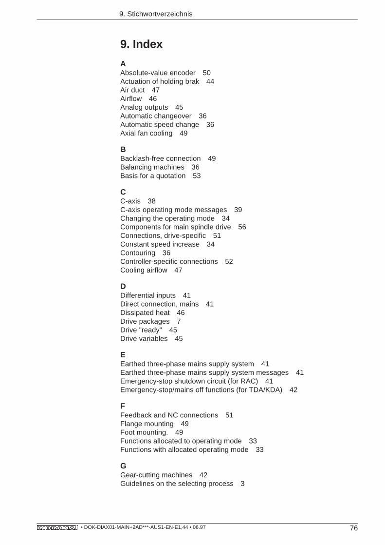
76• DOK-DIAX01-MAIN+2AD***-AUS1-EN-E1,44 • 06.97
9. Stichwortverzeichnis
9. Index
AAbsolute-value encoder 50Actuation of holding brak 44Air duct 47Airflow 46Analog outputs 45Automatic changeover 36Automatic speed change 36Axial fan cooling 49
BBacklash-free connection 49Balancing machines 36Basis for a quotation 53
CC-axis 38C-axis operating mode messages 39Changing the operating mode 34Components for main spindle drive 56Connections, drive-specific 51Constant speed increase 34Contouring 36Controller-specific connections 52Cooling airflow 47
DDifferential inputs 41Direct connection, mains 41Dissipated heat 46Drive packages 7Drive "ready" 45Drive variables 45
EEarthed three-phase mains supply system 41Earthed three-phase mains supply system messages 41Emergency-stop shutdown circuit (for RAC) 41Emergency-stop/mains off functions (for TDA/KDA) 42
FFeedback and NC connections 51Flange mounting 49Foot mounting. 49Functions allocated to operating mode 33Functions with allocated operating mode 33
GGear-cutting machines 42Guidelines on the selecting process 3
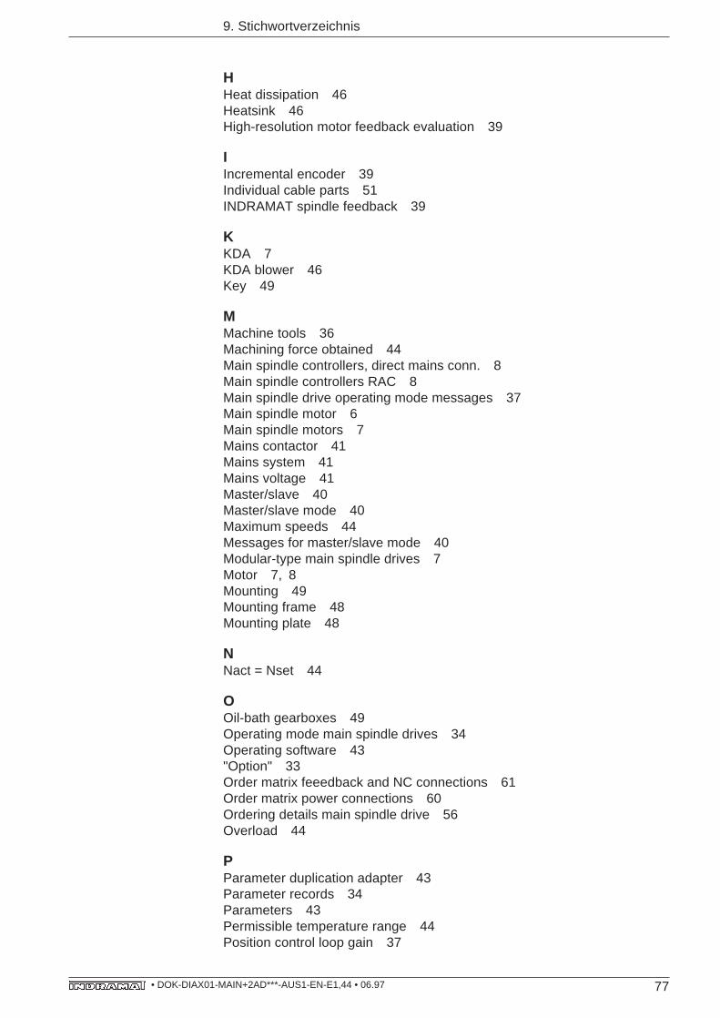
77• DOK-DIAX01-MAIN+2AD***-AUS1-EN-E1,44 • 06.97
9. Stichwortverzeichnis
HHeat dissipation 46Heatsink 46High-resolution motor feedback evaluation 39
IIncremental encoder 39Individual cable parts 51INDRAMAT spindle feedback 39
KKDA 7KDA blower 46Key 49
MMachine tools 36Machining force obtained 44Main spindle controllers, direct mains conn. 8Main spindle controllers RAC 8Main spindle drive operating mode messages 37Main spindle motor 6Main spindle motors 7Mains contactor 41Mains system 41Mains voltage 41Master/slave 40Master/slave mode 40Maximum speeds 44Messages for master/slave mode 40Modular-type main spindle drives 7Motor 7, 8Mounting 49Mounting frame 48Mounting plate 48
NNact = Nset 44
OOil-bath gearboxes 49Operating mode main spindle drives 34Operating software 43"Option" 33Order matrix feeedback and NC connections 61Order matrix power connections 60Ordering details main spindle drive 56Overload 44
PParameter duplication adapter 43Parameter records 34Parameters 43Permissible temperature range 44Position control loop gain 37
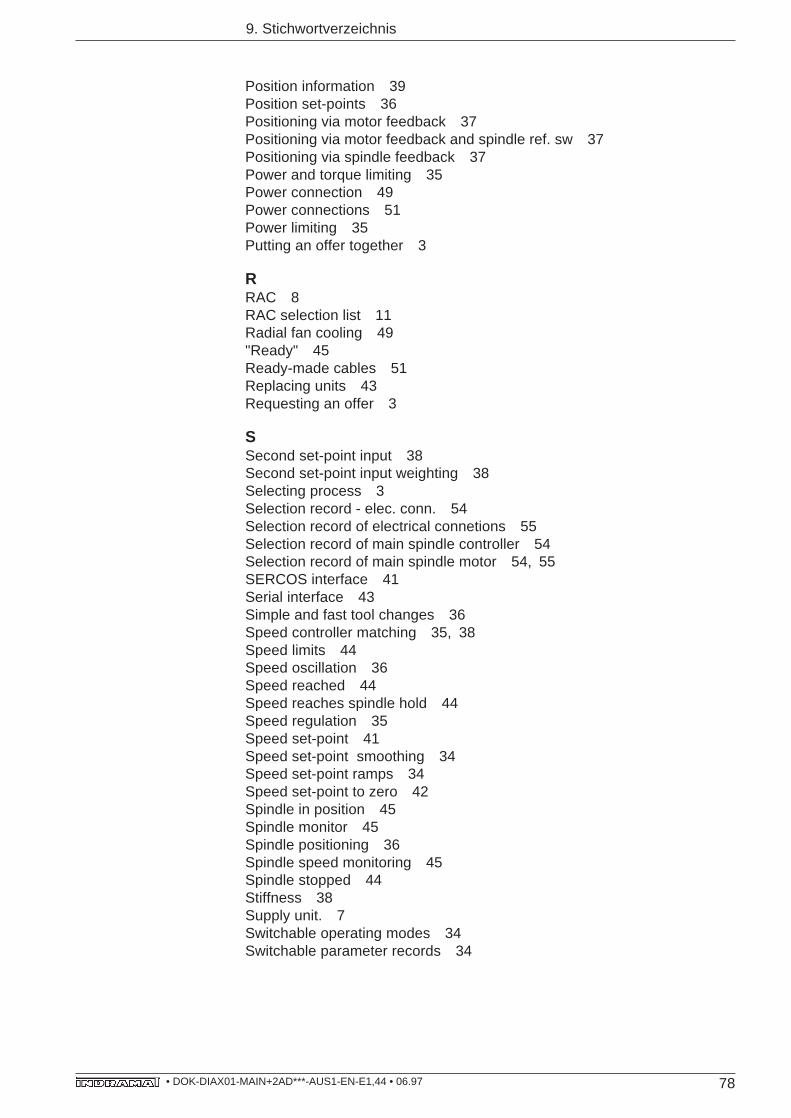
78• DOK-DIAX01-MAIN+2AD***-AUS1-EN-E1,44 • 06.97
9. Stichwortverzeichnis
Position information 39Position set-points 36Positioning via motor feedback 37Positioning via motor feedback and spindle ref. sw 37Positioning via spindle feedback 37Power and torque limiting 35Power connection 49Power connections 51Power limiting 35Putting an offer together 3
RRAC 8RAC selection list 11Radial fan cooling 49"Ready" 45Ready-made cables 51Replacing units 43Requesting an offer 3
SSecond set-point input 38Second set-point input weighting 38Selecting process 3Selection record - elec. conn. 54Selection record of electrical connetions 55Selection record of main spindle controller 54Selection record of main spindle motor 54, 55SERCOS interface 41Serial interface 43Simple and fast tool changes 36Speed controller matching 35, 38Speed limits 44Speed oscillation 36Speed reached 44Speed reaches spindle hold 44Speed regulation 35Speed set-point 41Speed set-point smoothing 34Speed set-point ramps 34Speed set-point to zero 42Spindle in position 45Spindle monitor 45Spindle positioning 36Spindle speed monitoring 45Spindle stopped 44Stiffness 38Supply unit. 7Switchable operating modes 34Switchable parameter records 34
79• DOK-DIAX01-MAIN+2AD***-AUS1-EN-E1,44 • 06.97
9. Stichwortverzeichnis
TTDA 7TDA/KDA selection list 10Temperature pre-warning 44To index the workpiece 36Torque control 40Torque limiting 35Torque output 40Types of controller-specific connections 52Types of feedback and NC connections 52Types of power connections 51
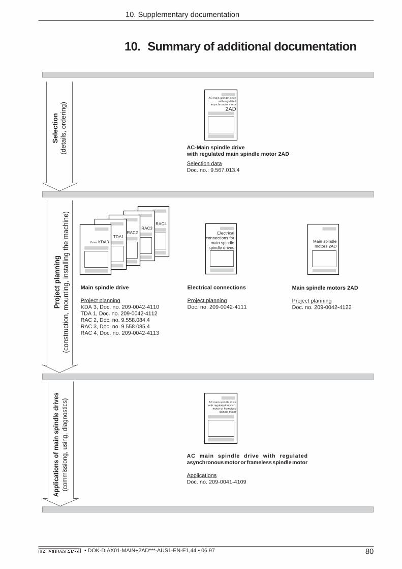
80• DOK-DIAX01-MAIN+2AD***-AUS1-EN-E1,44 • 06.97
10. Supplementary documentation
10. Summary of additional documentation
RAC4RAC3
RAC2TDA1
Drive KDA3
Electricalconnections for
main spindlespindle drives
Electrical connections
Project planningDoc. no. 209-0042-4111
Main spindle drive
Project planningKDA 3, Doc. no. 209-0042-4110TDA 1, Doc. no. 209-0042-4112RAC 2, Doc. no. 9.558.084.4RAC 3, Doc. no. 9.558.085.4RAC 4, Doc. no. 209-0042-4113
Sel
ectio
n(d
etai
ls, o
rder
ing)
Pro
ject
pla
nnin
g(c
onst
ruct
ion,
mou
ntin
g, in
stal
ling
the
mac
hine
)A
pplic
atio
ns o
f mai
n sp
indl
e dr
ives
(com
mis
sion
g, u
sing
, dia
gnos
tics) AC main spindle drive
with regulated asynch.motor or frameless
spindle motor
AC main spindle drive with regulatedasynchronous motor or frameless spindle motor
ApplicationsDoc. no. 209-0041-4109
Selection dataDoc. no.: 9.567.013.4
AC-Main spindle drivewith regulated main spindle motor 2AD
AC main spindle drivewith regulated
asynchronous motor
2AD
Main spindle motors 2AD
Project planningDoc. no. 209-0042-4122
Main spindlemotors 2AD
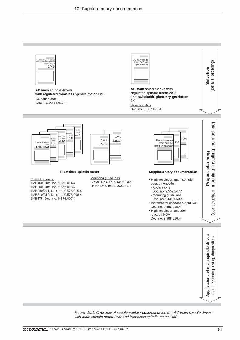
81• DOK-DIAX01-MAIN+2AD***-AUS1-EN-E1,44 • 06.97
Bausatzspindel-motor
1MB 375
10. Supplementary documentation
1MB- Stator1MB
- Rotor
HGVIGS
High-resolutionmain spindle
position encoder
Frameless spindle motor
Project planning1MB160, Doc. no. 9.576.014.41MB200, Doc. no. 9.576.016.41MB240/241, Doc. no. 9.576.015.41MB310/312, Doc. no. 9.576.008.41MB375, Doc. no. 9.576.007.4
Mounting guidelinesStator, Doc. no. 9.600.063.4Rotor, Doc. no. 9.600.062.4
Supplementary documentation
• High-resolution main spindle position encoder - Applications Doc. no. 9.552.247.4 - Mounting guidelines Doc. no. 9.600.060.4• Incremental encoder output IGS Doc. no. 9.568.015.4• High-resolution encoder junction HGV Doc. no. 9.568.010.4
Pro
ject
pla
nnin
g(c
onst
ruct
ion,
mou
ntin
g, in
stal
ling
the
mac
hine
)S
elec
tion
(det
ails
, ord
erin
g)
AC main spindle drive withregulated spindle motor 2ADand switchable planetary gearboxes2KSelection dataDoc. no. 9.567.022.4
AC main spindle driveswith regulated frameless
spindle motorr
1MB
AC main spindle driveswith regulated frameless spindle motor 1MBSelection dataDoc. no. 9.576.012.4
App
licat
ions
of m
ain
spin
dle
driv
es(c
omm
issi
onin
g, u
sing
, dia
gnos
tics)
Figure 10.1: Overview of supplementary documentation on "AC main spindle driveswith main spindle motor 2AD and frameless spindle motor 1MB"
Bausatzspindel-motor
1MB 310Bausatzspindel-
motor
1MB 240Bausatzspindel-
motor
1MB 200Frameless spindlemotor
1MB 160
AC main spindledrives 2AD with
gearboxes 2K

Indramat


