Embed Size (px)
Citation preview

1PmidpamcPprcbm
mtca(nwPdttapu[w
560 J. Opt. Soc. Am. B/Vol. 27, No. 3 /March 2010 Luo et al.
A spectral element method calculation ofextraordinary light transmission through periodic
subwavelength slits
Ma Luo,1 Qing Huo Liu,1,* and Junpeng Guo2
1Department of Electrical and Computer Engineering, Duke University, Durham, North Carolina 27708, USA2Department of Electrical and Computer Engineering, University of Alabama in Huntsville, Huntsville, Alabama
35899, USA*Corresponding author: [email protected]
Received October 20, 2009; accepted November 30, 2009;posted January 13, 2010 (Doc. ID 118795); published February 25, 2010
A spectral element method together with a surface integral equation as the radiation boundary condition isused to simulate the scattering properties of periodic subwavelength slits. The surface integral equation uti-lizes the periodic Green’s function in the wave number space and is solved by the method of moments, whilethe interior inhomogeneous medium is modeled by the spectral element method. The solution convergence isfound to be exponential; i.e., the error decreases exponentially with the order of basis functions. To our knowl-edge, such a fast solver with spectral accuracy is new in the scattering problem of periodic structures. Scat-tering properties of a gold slit grid within the whole wavelength-incidence angle parameter space are investi-gated, with the confirmation that strong transmission of light through subwavelength slits is achievable.© 2010 Optical Society of America
OCIS codes: 000.4430, 160.5298.
isstpTtgtfiroogmTp
ooligcadtitte
. INTRODUCTIONeriodic structures such as photonic crystals (PCs) haveany applications. Among different periodic structures,
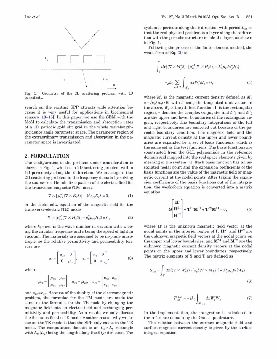
n this work we are particularly interested in two-imensional (2D) structures with one-dimensional (1D)eriodicity as shown in Fig. 1, where a 1D periodic PClong the x direction separates two half spaces of differentaterials. The incident light from the upper half space
an undergo an interesting scattering process by the 1DC, especially when the periodic structure consists of dis-ersive media (such as a metal in the optical frequencyegime). An analysis of such structures requires a very ac-urate modeling technique in order to capture narrow-and phenomena such as the extraordinary light trans-ission through subwavelength slits.We propose the combination of the spectral elementethod (SEM) with a surface integral equation to solve
his problem with high accuracy. The SEM [1–3] is a spe-ial kind of finite element method whose basis functionsre constructed by high-order Gauss–Lobatto–LegendreGLL) polynomials. This method was shown to have expo-ential convergence versus the order of basis functionshen it is used to solve the band structure of 2D periodicCs [4]. When the 2D PCs have a finite size along one �y�irection and an infinite size along another �x� direction,he scattering properties become an important issue. Athe boundary perpendicular to the periodic direction withn infinite size, the periodic boundary condition is still ap-licable. At the other two boundaries that separate thepper and lower half spaces, a surface integral equation5] is used to describe the radiation boundary conditionith a periodic Green’s function. Previously, the spectral
0740-3224/10/030560-7/$15.00 © 2
ntegral method (SIM) [6,7] has been used to solve theurface integral equation with spectral accuracy. The keytep is to remove the singular point of the Green’s func-ion when the observation point coincides with the sourceoint by subtracting a function with the same singularity.he analytical form of the Fourier transform of this func-
ion is known, which is used to calculate the surface inte-ral of this function. In this paper, we propose an alterna-ive scheme to treat the singularity of the periodic Green’sunction. Here, the periodic Green’s function is calculatedn the wave number domain, and transferred back to theeal space, which turns out to be a superposition of a setf plane waves. We use this wave number representationf the periodic Green’s function to solve the surface inte-ral equation so that the accuracy and efficiency of theethod of moments (MoM) can be as good as the SEM.herefore, the whole simulation method can have an ex-onential convergence.This 2D hybrid method is a general solver for 1D peri-
dic structures separating two different half spaces. Asne special application, it can be used to solve the prob-em of scattering properties of a slit grid. One of the mostnteresting topics in this area is the scattering of a slitrid consisting of a dispersive metal. The incident lightan excite surface plasmon polaritons (SPPs) [8], whichre coupled electromagnetic modes between free electronensity oscillations and electromagnetic fields. Sincehere is a momentum mismatch between the SPP and thencident photon, it needs additional momentum to excitehe SPP. Many schemes have been proposed to providehe additional momentum, such as Kretschmann and Ra-ther [9], Otto [10], and grating [11,12] schemes. The re-
010 Optical Society of America
scsMoitr
2Ts12tt
ot
wivts
w
apsmmtcmw
stti
w
w=tragarmatcdmsbnste
wnttupT
It
si
Fp
Luo et al. Vol. 27, No. 3 /March 2010/J. Opt. Soc. Am. B 561
earch on the exciting SPP attracts wide attention be-ause it is very useful for applications in biochemicalensors [13–15]. In this paper, we use the SEM with theoM to calculate the transmission and absorption rates
f a 1D periodic gold slit grid in the whole wavelength-ncidence angle parameter space. The parameter region ofhe extraordinary transmission and absorption in the pa-ameter space is investigated.
. FORMULATIONhe configuration of the problem under consideration ishown in Fig. 1, which is a 2D scattering problem with aD periodicity along the x direction. We investigate thisD scattering problem in the frequency domain by solvinghe source-free Helmholtz equation of the electric field forhe transverse-magnetic (TM) mode
� � ��rs−1�� � Ezz�� − k0
2�rzEzz = 0, �1�
r the Helmholtz equation of the magnetic field for theransverse-electric (TE) mode
� � ��rs−1�� � Hzz�� − k0
2�rzHzz = 0, �2�
here k0=� /c is the wave number in vacuum with � be-ng the circular frequency and c being the speed of light inacuum. The materials are assumed to be in-plane aniso-ropic, so the relative permittivity and permeability ten-ors are
�r = ��rs 0
0 �rz�, �r = ��rs 0
0 �rz� , �3�
here
�rs = ��xx �xy
�yx �yy� �rz = �zz, �rs = ��xx �xy
�yx �yy�
nd �rz=�zz. Because of the duality of the electromagneticroblem, the formulas for the TM mode are made theame as the formulas for the TE mode by changing theagnetic field into an electric field and exchanging per-ittivity and permeability. As a result, we only discuss
he formulas for the TE mode. Another reason why we fo-us on the TE mode is that the SPP only exists in the TEode. The computation domain is an Lx�Ly rectangleith L �L � being the length along the x �y� direction. The
Lx
Ly
x
y
ig. 1. Geometry of the 2D scattering problem with 1Deriodicity.
x y
ystem is periodic along the x direction with period Lx, sohat the real physical problem is a layer along the x direc-ion with the periodic structure inside the layer, as shownn Fig. 1.
Following the process of the finite element method, theeak form of Eq. (2) is
��
dr��� � Wj�z� · ��rs
−1�� � Hzz�� − k02�rzWj
�Hz
− jk0 b=1,2
���b
dxWj�Mz = 0, �4�
here Mz is the magnetic current density defined as Mz
−��0 /�0t ·E, with t being the tangential unit vector. Inhe above, Wj is the jth test function, � is the rectangularegion, � denotes the complex conjugate, and ��1 and ��2re the upper and lower boundaries of the rectangular re-ion, respectively. The boundary integrations of the leftnd right boundaries are canceled out because of the pe-iodic boundary condition. The magnetic field and theagnetic current density at the upper and lower bound-
ries are expanded by a set of basis functions, which ishe same set as the test functions. The basis functions areonstructed from the GLL polynomials in the referenceomain and mapped into the real space elements given byeshing of the system [4]. Each basis function has an as-
ociated nodal point and the expansion coefficients of theasis functions are the value of the magnetic field or mag-etic current at the nodal points. After taking the expan-ion coefficients of the basis functions out of the integra-ion, the weak-form equation is converted into a matrixquation
S�Hi
Hb1
Hb2 + T�1�Mb1 + T�2�Mb1 = 0, �5�
here Hi is the unknown magnetic field vector at theodal points in the interior region of �, Hb1 and Hb2 arehe unknown magnetic field vectors at the nodal points onhe upper and lower boundaries, and Mb1 and Mb2 are thenknown magnetic current density vectors at the nodaloints on the upper and lower boundaries, respectively.he matrix elements of S and T are defined as
Sj,k =��
dr��� � Wj�z� · ��rs
−1�� � Wkz�� − k02�rzWj
�Wk,
�6�
Tj,k�1,2� = − jk0�
��1,2
dxWj�Wk. �7�
n the implementation, the integration is calculated inhe reference domain by the Gauss quadrature.
The relation between the surface magnetic field andurface magnetic current density is given by the surfacentegral equation

wnpfitpbt
b
o(aib
w
Ttittfaawtpac
ati
pne
wMsasr
wptGaBt
Mf
w=st=bipttBcotaas(
562 J. Opt. Soc. Am. B/Vol. 27, No. 3 /March 2010 Luo et al.
Hzinc�x,y� =
1
2Hz�x,y� + jk0�rb� Gp
�b��kb�x − x��,kb�y
− y���Mz�x��dx�, �8�
here �rb and kb are the relative permittivity and waveumber of the background material above (below) the up-er (lower) boundary, with b=1,2; Hz
inc is the incidenteld, and Gp
�b� is the periodic Green’s functions in thesewo regions. The periodic Green’s functions contain theroperty of wave propagation in the upper and lowerackgrounds. Note that another integral in the surface in-egral equation becomes zero, i.e.,
� ��Gp�b��kb�x − x��,kb�y − y���/�y��y=y�Hz�x��dx� = 0
ecause
�Gp�b��kb�x − x��,kb�y − y���/�y = 0
n the two boundaries where y=y�. After transferring Eq.8) into a weak form and expanding the magnetic fieldnd magnetic current by the basis functions, the surfacentegral equation for the upper and lower boundaries cane written as two matrix equations, respectively,
U�1�Hb1 + V�1�Mb1 = F�1�,
U�2�Hb2 + V�2�Mb2 = F�2�, �9�
here
Uj,k�1,2� =
1
2���1,2
dxWj�Wk, �10�
Vj,k�1,2� = jk0�rb�
��1,2
���1,2
Wj��x�Gp
�b��kb�x
− x��,0�Wk�x��dxdx�, �11�
Fj�1,2� =�
��1,2
dxWj�Hinc. �12�
hese integrals are calculated in the reference domain byhe Gauss quadrature integration method. Note that thentegral in Eq. (11) is a nonlocal integral, which meanshat the integral is nonzero even when the two basis func-ions in the integral do not overlap. The periodic Green’sunction has singular points at x=x�+mLx, with m beingny integer. In order to calculate the integral with highccuracy and efficiency, we use the Green’s function in theave number space. Grouping Eqs. (5) and (9), the scat-
ering problem is described by the linear matrix equationroblem. The total field in the calculation region, as wells transmission, reflection, and absorption coefficients,an be obtained by solving this matrix equation.
The periodic Green’s function can be more easily evalu-ted in the wave number space than in the real space. Inhis paper, we restrict it to the case where the backgrounds a homogeneous isotropic dielectric material, but the up-
er and lower half spaces can be different. In a homoge-eous space, the Green’s function obeys the Helmholtzquation
�2Gb�r − r�� + kb2Gb�r − r�� = − ��r − r��, �13�
here kb is the wave vector in this homogeneous space.aking Fourier transform to the wave number space,
olving the Green’s function in the wave number space,nd making inverse Fourier transform back to the realpace, we have the Green’s function in the homogeneouseal space
Gb�r − r�� =� e−jq·�r−r��
�2��2�q2 − kb2�
dq, �14�
here q is the wave number vector. Since this is a 2Droblem, the integral is in the 2D wave number space. Ifhe system is periodic along the x direction, the periodicreen’s function obeys the same Helmholtz equation withsource term −me−jkxmLx��r−r�−mLx�, with kx being theloch wave number. As a result, the periodic Green’s func-
ion can be written as
Gpb�r − r�� =
me−jkxmLx� e−jq·�r−r�−mLxx�
�2��2�q2 − kb2�
dq
=�m
e−jkxmLx+jqxmLxe−jq·�r−r��
�2��2�q2 − kb2�
dq.
�15�
aking use of the Dirac comb function formulame−j�kx−qx�mLx= �2� /Lx�m��kx−qx−2�m /Lx�, and per-
orming the integration along qx, we have
Gpb�r − r�� =
me−jqx
m�x−x���2�
Lx�Im�kb,kx�, �16�
here qxm=kx−2�m /Lx and Im�kb ,kx�
�e−jqy�y−y��dqy / ��2��2�qxm+qy−kb
2��. In our problem, on theurface of the computation domain, y=y�, so the integra-ion along the qy direction becomes Im�kb ,kx��2� /Lx��dqy / ��2��2�qx
m+qy−kb2��, which can be evaluated
y the method of contour integral. The integration results Im�kb ,kx�= �2� /Lx��1/4�j�kb
2−qxm�. There are singular
oints when qxm−kb
2=0, which defines the light cone. Inhe numerical implementation, we only need to calculatehe problem away from the light cone most of the time.ut if we need to calculate the result at the light cone, weould use another pair of parameters �kb ,kx� which is outf the light cone and very close to the original parametero approximate. It is obvious that Im is a function of kbnd kx. Hence, the periodic Green’s function is written assummation of a set of plane waves, each of which is a
eparated function for x and x�. Inserting Eq. (16) into Eq.11), the integral is written as

wtfmocgbtmt
rlflpvcrer
wtd
wotims
3WhotsTe
ATsrtmsl
(twi
wlsciv
BGTgtwgtlwlcuifiu=tfi
w
Foptw
Luo et al. Vol. 27, No. 3 /March 2010/J. Opt. Soc. Am. B 563
Vj,k�1,2� = jk0�rb
m=−N
N
Im�kb,kx�����1,2
e−jqxmxWj
��x�dx����
��1,2
ejqxmxWk�x�dx� , �17�
here N is the cutoff of the summation, which is choseno be the same as the number of nodal points at the sur-ace so that the plane wave basis functions have approxi-ately the same sampling density in terms of the number
f points per wavelength. The two integrals in Eq. (17)an be calculated and stored in advance. Since the inte-rands are smooth functions, the integration results cane obtained very accurately by using the Gauss quadra-ure integration. The rapid calculation of the matrix ele-ents Vj,k
�1,2� can be implemented by the multiplication ofhe stored matrices of these integrals.
Some observable quantities, including the reflectionate, transmission rate, and absorption rate, are calcu-ated from the SEM solution of the field pattern. The re-ection rate and transmission rate are calculated by com-aring the integral of the vertical component of Poyntingectors along the upper and lower boundaries with the in-idence energy of the incident plane wave. The absorptionate can be calculated in two ways: one way is to use thenergy conservation principle that gives the absorptionate as
a = 1 − r − t, �18�
here a is the absorption rate, r is the reflection rate, andis the transmission rate; another way is to compare theissipated energy
Pd =1
2��
����E�2dr �19�
ith the incident energy, where �� is the imaginary partf the permittivity � and E is the electric field. In the sys-ems that we have investigated, only gold has a nonzeromaginary part. The numerical results show that the two
ethods give the same absorption rate. As a result, all ab-orption is due to the loss in gold.
. NUMERICAL RESULTSe have first validated the method with a simple system
aving one half space filled with one material and thether half space filled with another material. As this scat-ering problem has an analytical solution, it is used to in-pect the relative error of the SEM simulation results.hen, we use the method to calculate the scattering prop-rties of a gold slit grid on a glass surface.
. Convergence of Relative Errorhe first example we calculate is scattering from a halfpace interface. The calculation region is divided into twoectangular elements, with the upper one being air andhe lower one filled with a dielectric material with a per-ittivity equal to 3 as shown in Fig. 2(a). The result of the
cattering under 45° incidence is compared with the ana-ytical result, and the relative errors of the field pattern
L2 error), reflection rate, and transmission rate versushe sampling density in terms of the number of points peravelength are plotted in Fig. 2(b). The L2 relative error
s defined as
e =
���
�Hz − Hzexact�2dr
���
�Hzexact�2dr
, �20�
here Hzexact is the exact field pattern of the analytical so-
ution. As we can observe, the calculation result with aampling density fewer than five points per wavelengthan have a relative error less than 10−3. The straight linesn Fig. 2(b) show that the SEM has an exponential con-ergence.
. Extraordinary Transmission and Absorption of aold Slit Gridhe material configuration of the system being investi-ated in this subsection is shown in Fig. 3. Since the sys-em is periodic along the x direction, only one unit cellith width Lx is plotted. Figure 3(a) shows a square goldrid. A gold film with thickness d is deposited betweenwo kinds of dielectric materials filled in the upper andower backgrounds. A grid of slits in the gold film withidth s is filled with the same dielectric material as the
ower background. In applications, the upper backgroundould be a prism and the lower background could be a liq-id. The fill factor is defined as f=s /Lx. A plane wave is
ncident from the upper space. The permittivity of gold isrequency dependent and its dispersion curve is describedn [16–18]. In this example, the relative permittivity val-es of the upper and lower background materials are �r11.7232 and �r1=1.3332, respectively. Figure 3(b) shows a
riangular gold grid, which has the same area of goldlled in one unit cell as the system in Fig. 3(a).The transmission (a) and absorption (b) rates versus
avelength and incidence angle of a square gold grid sys-
2 3 4 5 6 7
10−8
10−6
10−4
10−2
100
(b)
points per wavelength
|rel
ativ
eer
ror|
L2
reflection
transmission
(a)
Lx
Ly
n1
n2
ig. 2. (a) Geometry of a half space interface. (b) Relative errorsf the field pattern, reflection rate, and transmission rate com-ared to the analytical solution of a half space interface versushe sampling density in terms of the number of points peravelength.

tFr5flgradiwtpdm
dfie
gotpricroaOparnamtgsFtvetsrrfiphchccas
Fsttoatdwaoi
Fr=
Fr=
564 J. Opt. Soc. Am. B/Vol. 27, No. 3 /March 2010 Luo et al.
em with Lx=200 nm, d=200 nm, and f=0.2 are plotted inig. 4. At a wavelength around 1000 nm, the transmissionate is very large when the incidence angle is less than0.7°, which is the critical angle of the total internal re-ection. The absorption rate is very large in several re-ions. The large absorption below 500 nm is due to theelatively large imaginary part of the electric permittivitynd the enhanced energy confinement inside the metalue to the close to zero real part of the electric permittiv-ty. The other regions are some small area regions at theavelength around 700 nm and incidence angle larger
han 50.7°. In these regions, the imaginary part of theermittivity of gold is very small; therefore, the extraor-inary absorptions are due to the coupling to the SPPodes in the subwavelength metal structure. The inci-
(a)(b)
Au
s
n1
n2
Lx
d
θ θ
2d
Lx
n2
n1
(b)
Au
s
ig. 3. (Color online) Two configurations of a unit cell of a goldlit grid. The upper and lower half spaces are filled with dielec-ric materials with reflective indices n1 and n2, respectively. Thehird material, gold in this case, is deposited under the interfacef the two dielectric materials. In system (a), the gold grid is rect-ngular; the period along the x direction is Lx, the thickness ofhe gold film is d, and the width of the slit is s. The fill factor isefined as f=s /Lx and � is the angle of incidence of the planeave. In the system (b), the gold grid is triangular; the periodnd width of the slit are the same as in system (a), but the heightf the gold triangle is 2d, so that the area of gold is the same asn (a).
ig. 4. (Color online) (a) Transmission rate and (b) absorptionate of a square gold grid with Lx=200 nm, d=200 nm, and f0.2.
ent light is coupled to the SPP modes, which focus theeld in the gold film and promote the absorption, andventually the energy is damped into the metal.
As a comparison, we calculated another square goldrid system, which has a thickness d=50 nm while thether parameters remain the same as the previous sys-em. The transmission (a) and absorption (b) rates arelotted in Fig. 5. The region with a large transmissionate shifts up to a larger wavelength. The absorption raten the large region with a wavelength under 500 nm be-omes smaller, which proves that the large absorptionate in this region is attributed to the internal absorptionf gold depending on the thickness of the gold film. Thebsorption rate at the other small region is still large.ne more small region with a large absorption rate ap-ears at the wavelength about 600 nm and incidencengle larger than 50.7°. As a result, the large absorptionate at these small regions is proved to be the extraordi-ary absorption because of the structure of the system. Ascomparison, the numerical results given by the Fourierodal method (FMM) [19–23] and by the SEM are plotted
ogether in Figs. 6(a) and 6(b). The agreement is veryood. We have also compared the numerical results of aystem with a fill factor f=0 with analytical solutions inigs. 6(c) and 6(d). The straight line in Fig. 6(d) showshat the numerical SEM solution has an exponential con-ergence and even the second order SEM has a relativerror smaller than 0.1%. Another advantage of the SEM ishat it can solve systems with more complicated spatialtructures by making the mesh conformal to the geomet-ic structure. The transmission (a) and absorption (b)ates of a triangular gold grid with the same area of goldlled in one unit cell as the square gold grid in Fig. 5 arelotted in Fig. 7. It is shown that the large region with aigh absorption rate is almost the same, which is only de-ided by the area of gold filled. The small regions with aigh absorption rate become wider and have different lo-ations; the region with a high transmission rate also be-omes larger. This is because the triangular gold grid hasdifferent dispersive relation of the SPP modes from the
quare gold grid.
ig. 5. (Color online) (a) Transmission rate and (b) absorptionate of a square gold grid with Lx=200 nm, d=50 nm, and f0.2.

tcslFlaatta=t
ttnwetLwswitrvllrtLtati
4TmsSMtpnorTcwevea
Fstd(Sa2vt
Frf
Fw
Luo et al. Vol. 27, No. 3 /March 2010/J. Opt. Soc. Am. B 565
For both systems in Figs. 4, 5, and 7, there is a smallransmission rate at a wavelength under 600 nm and in-idence angle larger than 50.7°. A third square gold gridystem with Lx=600 nm, d=600 nm, and f=0.2 was simu-ated as a comparison. The transmission rate is plotted inig. 8, which shows that there is a large region with a
arge transmission rate at the wavelength under 2000 nmnd incidence angle larger than 50.7°. This transmissiont the angle larger than the critical angle is attributed tohe assistance of periodic structure. Considering the sys-em without the gold grid, the relation between incidentngle �in and refractive angle �re is sin��in�n1k0sin��re�n2k0=kx, with kx being the wave number of the
raveling wave along the x direction, so the phase along
45 50 550
0.2
0.4
0.6
0.8
1
incidence angle
refle
ctio
nra
te(a)
45 50 550
0.2
0.4
0.6
0.8
1
incidence angle
abso
rptio
nra
te
(b)
0 20 40 60 800
0.2
0.4
0.6
0.8
1
incidence angle
refle
ctio
nra
te
(c)
2 3 4 510
−7
10−6
10−5
10−4
10−3
order of SEM
|rel
ativ
eer
ror|
(d)
ig. 6. (Color online) Accuracy analysis of the SEM. Compari-on of the reflection rate (a) and absorption rate (b) obtained byhe fifth order SEM (blue dotted line), the ninth order SEM (redashed line), and the FMM (black line) for the system in Fig. 5.c) Comparison of the reflection rate obtained by the third orderEM (blue dotted line), the fifth order SEM (red dashed line),nd the analytical solution (black line) with fill factor f=0 and00 nm thick gold film. (d) The relative error of reflection rateersus the order of the SEM. The wavelength of these calcula-ions is 850 nm.
ig. 7. (Color online) (a) Transmission rate and (b) absorptionate of a triangular gold grid with Lx=200 nm, 2d=100 nm, and=0.2.
he x direction matches at the interface. If kx is largerhan n2k0, then ky in the lower half space must be imagi-ary, because �n2k0�2=kx
2+ky2. In this case, the refractive
ave becomes an evanescent wave that does not transfernergy along the y direction, so the incident wave is to-ally reflected. When there is a periodic grid with periodx, the wave number along the x direction of the refractedave could be kx+2�m /Lx, with m being any integer to
atisfy the phase matching condition. When one of theseave numbers is smaller than n2k0, the corresponding ky
n the lower half space is real, so the refracted wave is araveling wave along the y direction and the transmissionate is nonzero. Obviously, there is a possibility of thealue of m being 1 or a smaller integer. When Lx isarger, 2� /Lx becomes smaller, so m with a larger abso-ute value can satisfy the traveling wave condition. As aesult, the transmission at the incidence angle largerhan 50.7° is larger when Lx=600 nm than that whenx=200 nm. Note that when the grid consists of a dielec-
ric material with a positive permittivity value, there islso transmission at this condition. This means that thisransmission is not attributed to the negative permittiv-ty of gold.
. CONCLUSIONhe spectral element method (SEM) together with theethod of moments (MoM) is used to simulate the 2D
cattering of a gold slit grid with a 1D periodic structure.ince the SEM has very high accuracy and efficiency, theoM part has been improved so that the whole simula-
ion can have high accuracy and efficiency. As a result, theeriodic Green’s function is transformed into the waveumber representation given by Eq. (16). The calculationf the matrix elements in the MoM using this form of pe-iodic Green’s function is easier to achieve high accuracy.he solution convergence is tested by comparing the cal-ulation results of the scattering of a half space interfaceith analytical solutions. The numerical results show anxponential convergence. The method is then used to in-estigate the scattering properties of gold slit grids. Thextraordinary transmission and extraordinary absorptionre investigated over the incidence angle-wavelength pa-
ig. 8. (Color online) Transmission rate of a square gold gridith Lx=600 nm, d=600 nm, and f=0.2.
rssesesii
ATu
R
1
1
1
1
1
1
1
1
1
1
2
2
2
2
566 J. Opt. Soc. Am. B/Vol. 27, No. 3 /March 2010 Luo et al.
ameter space. An extraordinary transmission rate atome wavelength and extra-large absorption at somemall regions of the wavelength-incidence angle param-ter space are found. The extraordinary absorption atome regions of the wavelength-incidence angle param-ter space is due to the excitation of the SPP modes in theubwavelength metal structures. The transmission at anncidence angle larger than the critical angle of the totalnternal reflection is enhanced by the periodic grid.
CKNOWLEDGMENThe support from the National Science Foundation (NSF)nder grant CCF-0621862 is appreciated.
EFERENCES1. J.-H. Lee and Q. H. Liu, “An efficient 3-D spectral element
method for Schrodinger equation in nanodevicesimulation,” IEEE Trans. Comput.-Aided Des. 24,1848–1858 (2005).
2. G. C. Cohen, Higher-Order Numerical Methods forTransient Wave Equations (Springer, 2001).
3. J.-H. Lee, T. Xiao, and Q. H. Liu, “A 3-D spectral elementmethod using mixed-order curl conforming vector basisfunctions for electromagnetic fields,” IEEE Trans.Microwave Theory Tech. 54, 437–444 (2006).
4. M. Luo, Q. H. Liu, and Z. Li, “Spectral element method forband structures of two-dimensional anisotropic photoniccrystals,” Phys. Rev. E 79, 026705 (2009).
5. J. Liu and Q. H. Liu, “A novel radiation boundary conditionfor finite-element method,” Microwave Opt. Technol. Lett.49, 1995–2002 (2007).
6. F. Q. Hu, “A spectral boundary integral equation methodfor the 2D Helmholtz equation,” J. Comput. Phys. 120,340–347 (1995).
7. J. Liu and Q. H. Liu, “A spectral integral method (SIM) forperiodic and nonperiodic structures,” IEEE Microw. Wirel.Compon. Lett. 14, 97–99 (2004).
8. H. Raether, Surface Plasmons on Smooth and RoughSurfaces and on Gratings (Springer-Verlag, 1988).
9. E. Kretschmann and H. Raether, “Radiative decay ofnonradiative surface plasmons excited by light,” Z.Naturforsch. A 23, 2135–2136 (1968).
0. A. Otto, “Excitation of nonradiative surface plasma waves
in silver by the method of frustrated total reflection,” Z.Phys. 216, 398–410 (1968).
1. Y.-Y. Teng and E. A. Stern, “Plasma radiation from metalgrating surfaces,” Phys. Rev. Lett. 19, 511–514 (1967).
2. R. H. Ritchie, E. T. Arakawa, J. J. Cowan, and R. N.Hamm, “Surface-plasmon resonance effect in gratingdiffraction,” Phys. Rev. Lett. 21, 1530–1533 (1968).
3. C. J. Alleyne, A. G. Kirk, R. C. McPhedran, N.-A. P.Nicorovici, and D. Maystre, “Enhanced SPR sensitivityusing periodic metallic structures,” Opt. Express 15,8163–8169 (2007).
4. K. M. Byun, S. J. Kim, and D. Kim, “Design study of highlysensitive nanowire-enhanced surface plasmon resonancebiosensors using rigorous coupled wave analysis,” Opt.Express 13, 3737–3742 (2005).
5. K. M. Byun, M. L. Shuler, S. J. Kim, S. J. Yoon, and D.Kim, “Sensitivity enhancement of surface plasmonresonance imaging using periodic metallic nanowires,” J.Lightwave Technol. 26, 1472–1478 (2008).
6. P. G. Etchegoin, E. C. Le Ru, and M. Meyer, “An analyticmodel for the optical properties of gold,” J. Chem. Phys.125, 164705 (2006).
7. P. G. Etchegoin, E. C. Le Ru, and M. Meyer, “Erratum: Ananalytic model for the optical properties of gold,” J. Chem.Phys. 127, 189901(E) (2007).
8. A. D. Rakic, A. B. Djurisic, J. M. Elazar, and M. L.Majewski, “Optical properties of metallic films for vertical-cavity optoelectronic devices,” Appl. Opt. 37, 5271–5283(1998).
9. H.-S. Leong, J. Guo, R. G. Lindquist, and Q. H. Liu,“Surface plasmon resonance in nanostructured metal filmsunder the Kretschmann configuration” J. Appl. Phys. 106,124314 (2009).
0. T. Tamir, H. C. Wang, and A. A. Oliner, “Wave propagationin sinusoidally stratified dielectric media,” IEEE Trans.Microwave Theory Tech. 12, 323–335 (1964).
1. C. B. Burckhardt, “Diffraction of a plane wave at asinusoidally stratified dielectric grating,” J. Opt. Soc. Am.56, 1502–1508 (1966).
2. M. G. Moharam and T. K. Gaylord, “Rigorous coupled-waveanalysis of metallic surface-relief gratings,” J. Opt. Soc.Am. A 3, 1780–1787 (1986).
3. M. G. Moharam, E. B. Grann, D. A. Pommet, and T. K.Gaylord,“Formulation for stable and efficientimplementation of the rigorous coupled-wave analysis ofbinary gratings,” J. Opt. Soc. Am. A Opt. Image Sci. Vis 12,1068–1076 (1995).


