Embed Size (px)
Citation preview
1A Primer on Oils
Processing Technology
Dan Anderson
1. INTRODUCTION
In the early days of oilseed production, functions were often far removed, and
actions taken by one operation were done for optimization of its own performance
with little consideration on impacts made on subsequent processes. For example,
the elevator dryer operator, in order to get the maximum grain throughput during
busy harvest periods, might dry grain at an excessively hot temperature without
considering the impact on the oil quality. The degumming operator may set the cen-
trifuge to take advantage of trading rule limits without regard of the downstream
impact on the refining operation.
Within the last few years, the emphasis has changed from stand-alone operations
toward the integrated manufacturing facility, producing a more complete range of
value-added products from the raw seed to the dinner table. During this transition,
operations have become more dependent on each other, as the individual functions
involved must now consider the impact of their actions on the total process. At the
same time, the scope of knowledge each operation must have of other functions
has expanded, and it is important that at least a basic understanding of the ‘‘big
picture’’ be available to the decision maker. The purpose of this Chapter is to
provide an overview of the typical processes and interrelations associated with a total
integrated facility. It is also hoped this basic overview will prove to be beneficial
Bailey’s Industrial Oil and Fat Products, Sixth Edition, Six Volume Set.Edited by Fereidoon Shahidi. Copyright # 2005 John Wiley & Sons, Inc.
1
to those new in the industry. It must be stressed that this Chapter attempts to touch
in a limited number of pages subjects that are the basis for volumes of books and
lifetimes of knowledge. It must also be emphasized that this Chapter does not
expand the many viable options of each type of process, nor does it intend to pro-
vide details for proper operation of each of the unit operations. For a more detailed
discussion, the reader is encouraged to refer to the many fine chapters within this
series and other publications dealing in much greater detail with each of the indi-
vidual functions of the integrated facility.
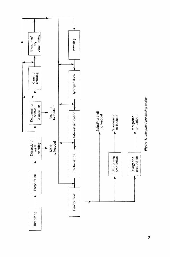
It is useful to consider the modern manufacturing operation as a set of unit
operations and develop a block diagram representing the facility. Figure 1 illustrates
the processes involved with the subsequent sections of this Chapter reviewing these
unit operations.
2. STORAGE
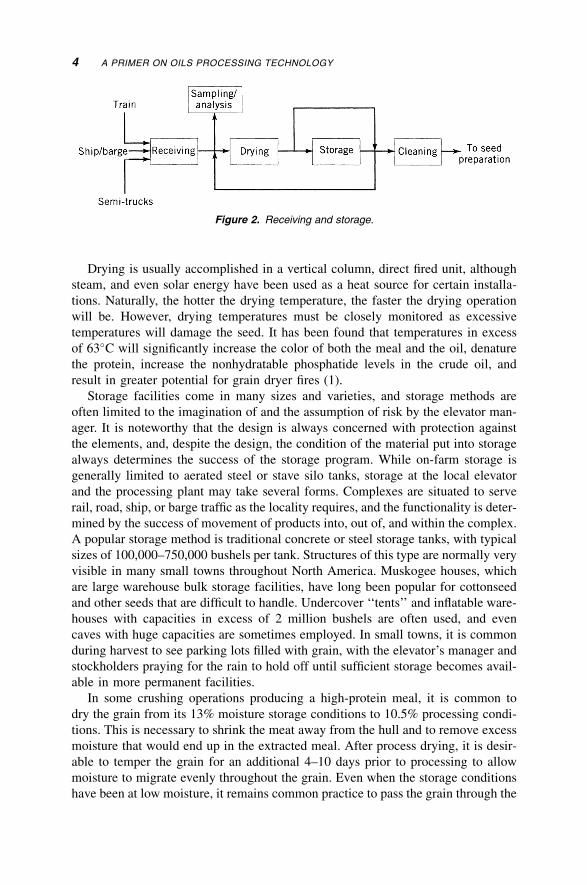
The typical operations associated with storage include receiving, sampling, drying,
storage, and cleaning prior to processing. Figure 2 illustrates the common functions
of this operation. There are many variants; for example, some processors may clean
the grain both before and after the drying operations. In any case, the basic opera-
tions are designed to accomplish the same task, which is to provide a safe haven
for the grain and deliver it at the proper time and condition to the processing
facility.
As the product is received fresh from the farmer’s field, the grain will contain
foreign material, consisting of naturally occurring sticks and pods, metal and
rock accumulated during handling, and contamination from weed seeds and other
grains. The elevator manager will sample the grain and make adjustments in the
price paid based on the moisture, splits, heat damage, and other factors. Typically
grain receipts are segregated based on these quality factors, with the moisture con-
tent being one of the prime factors for separation. For proper storage and subse-
quent processing, the contaminants must be removed and the grain must be dried
prior to storage. As grain freshly harvested may have a moisture content of up to
20% (although many farm operations are equipped with dryers), the grain must
generally be dried to around 13% moisture for safe extended storage. High moisture
damage typically results in reduced oil content, decreased protein, and increased
color and refining loss of the extracted oil (1). A precursor to this damage is often
indicated by a rising grain temperature, and many storage facilities are equipped
with a series of temperature cables embedded in the grain with indicating and
recording equipment located in the manager’s office. If left unchecked, the grain
will spontaneously heat and become damaged and under extreme conditions, a
serious fire may develop. It is routine practice to monitor the temperature of the
grain daily and, if heating is occurring, immediately process the grain. If this is not
possible, or the degree of heating is not severe, the elevator manager may simply
‘‘rotate’’ the grain by moving it from one location to another.
2 A PRIMER ON OILS PROCESSING TECHNOLOGY
Fig
ure
1.
Inte
gra
ted
pro
cessin
gfa
cili
ty.
3
Drying is usually accomplished in a vertical column, direct fired unit, although
steam, and even solar energy have been used as a heat source for certain installa-
tions. Naturally, the hotter the drying temperature, the faster the drying operation
will be. However, drying temperatures must be closely monitored as excessive
temperatures will damage the seed. It has been found that temperatures in excess
of 63�C will significantly increase the color of both the meal and the oil, denature
the protein, increase the nonhydratable phosphatide levels in the crude oil, and
result in greater potential for grain dryer fires (1).
Storage facilities come in many sizes and varieties, and storage methods are
often limited to the imagination of and the assumption of risk by the elevator man-
ager. It is noteworthy that the design is always concerned with protection against
the elements, and, despite the design, the condition of the material put into storage
always determines the success of the storage program. While on-farm storage is
generally limited to aerated steel or stave silo tanks, storage at the local elevator
and the processing plant may take several forms. Complexes are situated to serve
rail, road, ship, or barge traffic as the locality requires, and the functionality is deter-
mined by the success of movement of products into, out of, and within the complex.
A popular storage method is traditional concrete or steel storage tanks, with typical
sizes of 100,000–750,000 bushels per tank. Structures of this type are normally very
visible in many small towns throughout North America. Muskogee houses, which
are large warehouse bulk storage facilities, have long been popular for cottonseed
and other seeds that are difficult to handle. Undercover ‘‘tents’’ and inflatable ware-
houses with capacities in excess of 2 million bushels are often used, and even
caves with huge capacities are sometimes employed. In small towns, it is common
during harvest to see parking lots filled with grain, with the elevator’s manager and
stockholders praying for the rain to hold off until sufficient storage becomes avail-
able in more permanent facilities.
In some crushing operations producing a high-protein meal, it is common to
dry the grain from its 13% moisture storage conditions to 10.5% processing condi-
tions. This is necessary to shrink the meat away from the hull and to remove excess
moisture that would end up in the extracted meal. After process drying, it is desir-
able to temper the grain for an additional 4–10 days prior to processing to allow
moisture to migrate evenly throughout the grain. Even when the storage conditions
have been at low moisture, it remains common practice to pass the grain through the
Figure 2. Receiving and storage.
4 A PRIMER ON OILS PROCESSING TECHNOLOGY
dryer to help shrink the hull from the meat, allowing the subsequent dehulling step
to be performed more effectively. This additional preprocessing step does increase
operating costs, not only because of the energy spent to heat the grain, but also
because this represents one additional unit operating with associated depreciation,
operating, and handling losses. There are new technologies available for dehulling
integrated in the preparation process that largely eliminate the need for a process
dryer.
Cleaning methods vary greatly depending on the seed received, but typically
consist of a magnet designed to remove tramp metal, a scalper designed to remove
large and heavy materials, and a sizing screener designed to remove fine and over-
sized materials. Aspiration may also be employed to assist in removal of light
foreign material. While contaminants removed by the magnet and scalper are nor-
mally discharged as waste, contaminants separated in the cleaner may be ground
and reintroduced into the meal stream, or may be used as fillers in feed rations.
In addition to cleaning, cottonseed is often delinted prior to preparation, with the
lint fibers removed by a series of saw cutters prior to processing.
3. PREPARATION
The function of the preparation process is to properly prepare the seeds for
extraction of the oil, either by solvent or mechanical methods and, if applicable,
remove the hulls and other materials from the seed kernel or meat. While a parti-
cular seed may contain from 20 to 50% oil, the oil is tightly bound within the cell
and mechanical action must be taken to either forcefully remove the oil or to make
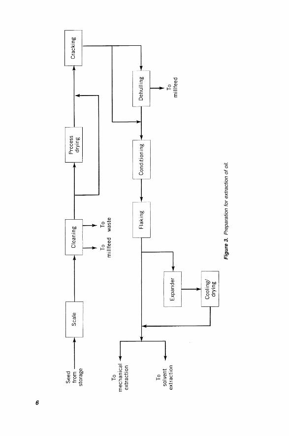
the oil more accessible to subsequent solvent extraction. The unit operations typi-
cally involved are illustrated in Figure 3, and usually involve scaling, cleaning,
cracking, conditioning (or cooking), and flaking. Depending on the process and
the oilseed in question, process drying, and dehulling (or decorticating) may be
employed, as may be expanders and collet dryer/coolers. After the preparation pro-
cess, the prepared flakes or collets are delivered to the extraction operation.
Once arriving in the preparation facility, the seed is usually scaled through a
weighing device or other control means. The scale is often used to check the
physical inventory of seed against the production accumulated, with the difference
reconciled as shrinkage. After weighing the seed, it is then delivered to the cleaning
process, which generally follows the same path as that described in the receiving
operation. After cleaning, cottonseed and sunflower seeds may be dehulled by
impacting the seed, breaking and separating the hulls. The hulls may be used as
a solid fuel source for boiler operations or for animal feed supplement. The tradi-
tional process continues with the cracking rolls, which are a set of two- or three-
high corrugated rolls turning at relatively high speeds that break the grain into
several pieces. For the soybean processor producing high-protein meal, the cracking
breaks the bond between the meats and the hulls, and in the traditional process the
hulls are then removed by aspiration. After dehulling, the meats are delivered to
PREPARATION 5
Fig
ure
3.
Pre
para
tion
for
extr
action
of
oil.
6
the conditioner (or cooker) where heat is gently applied to make the cracks soft and
pliable for the subsequent flaking operation described later in this section.
There have been several novel approaches applied to preparation in the past few
years. One concept that has been widely accepted, especially for soybean proces-
sing, is hot dehulling. After traditional cleaning, the seed may be delivered directly
to the crackers or may enter the hot dehulling operation. As mentioned before, use
of this technology generally eliminates the process drying step traditionally identi-
fied with the storage function. The basic principle shared by the three commonly
used hot dehulling systems is to dry the bean from storage moisture to process
moisture, dehull the seed while still hot, and deliver the conditioned cracks to
the flakers without allowing the seed to subsequently cool. This not only saves the
energy of one heating step, as much of the air is recycled reducing the energy
required for the integrated facility, but reduces the fines generated compared with
the traditional system where the grain is cracked cold. One system that has gained
wide acceptance is the Escher-Wyss system, which uses a fluid-bed dryer-heater to
perform the drying process. After the dryer-heater the grain is discharged to speci-
ally designed high-speed cracking rolls, where the seed is cracked while still hot,
and then delivered to special high-shear impactors to separate the meats and hulls.
The product is then delivered to aspirators, where the hulls are removed, and then to
the conditioner, which allows the meats to cool slightly and to temper prior to flak-
ing. Another process that has gained acceptance is the Buhler hot dehulling system,
which uses a conditioning column with steam-heated elements to slowly bring the
beans to 65�C. The beans are then subjected to a short treatment in a fluid-bed
popper where the hull–meat bond is broken. The beans are then broken in half
by impact splitters, the hulls removed in an aspirator, and the splits further cracked
and sent to the flaking rolls. The Crown hot dehulling system uses a similar con-
ditioning column followed by a jet dryer to crisp the soybean hull and free it from
the meat. A proprietary Hulloosenator then splits the bean and rolls the hulls free
where they are aspirated from the meats. The splits are then cracked to the final
size for flaking and sent to the Crown Cascade Conditioner for additional aspiration
with temperature and moisture adjustment. In addition to the obvious energy sav-
ings, these types of systems are reported to reduce residual oil content, improve
extractability, and reduce refining loss (2). In all cases, the comments on drying
temperatures presented during discussion of storage drying are valid with hot dehul-
ling systems.
While having received the greatest attention, cottonseed, sunflower, and soy-
beans are not the only oilseeds suitable for dehulling operations. There is research
underway to produce a dehulled canola seed. Removing the hulls will increase the
protein content and reduce the fiber content of the meal making the product
more attractive for feed formulation. A variety of methods have been tested, with
encouraging results, although no commercial system has yet been installed.
After conditioning, the meats are generally passed to the flaking rolls where the
cell wall is distorted, making the oil more accessible. The rolls being relatively
large (70 � 157 cm or larger) are held together with hydraulic or mechanical pres-
sure, squeeze the meats into flakes of approximately 0.30 mm thickness. For grains
PREPARATION 7
with lower oil content such as soybeans, the flakes are typically delivered directly to
the solvent extraction plant. For oilseeds with higher oil concentrations, such as
sunflower or canola, or installations where solvent extraction is not employed, the
flakes are typically sent to mechanical pressing equipment.
A number of processes have been applied to enhance oil extractability and to
improve conditions for consistent physical refining. One of the greatest problems
associated with physical refining of high-phosphorous oils (such as soybean or
corn) is that nonhydratable phosphatides generally cannot be removed without
extensive bleaching clays and acid treatments. Because of variances in the crop
year, growing conditions, and seed varieties, consistency in the oil is a major factor
affecting successful application of physical refining. It is postulated that the pre-
sence of an enzyme during conditions associated with certain storage conditions
and the subsequent extraction process causes water-hydratable phosphatides to
become nonhydratable. Activity of this enzyme is directly impacted by the seed
and growing conditions. Lurgi’s Alcon process is said to inactivate this enzyme
immediately after the flaking step, and provide an oil consistently acceptable for
physical refining (3). This process is said to also reduce hexane carryover, although
the characteristics of the meal are somewhat different from that obtained from a
conventional process. Lecithin produced from degumming the oil is also affected.
Another process that has gained much popularity, especially for deep-bed extrac-
tion installations, is expanders. These devices, which operate much the same as
mechanical presses but with less pressure, substantially increase the bulk density
of the flakes prior to extraction. This allows the processor to increase the throughput
of the plant with minimal capital investment, as the oilseed extractability and gravi-
metric throughput is greatly enhanced. It was originally postulated that the empha-
sis on thin flaking may be reduced with expanders with one process designer even
proposing elimination of flakers, simply grinding the grain prior to the expander.
While elimination of the energy, maintenance, and capital investment associated
with flaking is certainly attractive, tests to date indicate that thin flaking is still
necessary to produce an acceptable residual flake fat.
The use of expanders does have an impact on the quality of the oil that the inte-
grated processor should be aware of. An interesting phenomena of the expander is
that while phosphorous levels in the extracted crude oil are normally increased over
traditional flake extraction (typically as much as 200 ppm as P in soybean oil), non-
hydratable levels in the degummed oil are normally lower. It is postulated that
partial inactivation of the lipase enzyme (blamed for conversion of nonhydratable
phosphatides) occurs in the expander and, while the crude oil has a higher neutral
oil loss, the quality of the degummed oil is higher. In fact, one processor reported
that despite all efforts to make a soybean oil physical refining plant function, the oil
was of substandard quality until the plant installed expanders. Once installed, the
plant could consistently produce a quality physical refined oil (4).
Expanders do have an impact on lecithin production as well, not only in terms of
higher quantity but also with respect to the quality. Expanders continue to gain
acceptance, and several variations have been introduced for high oil content appli-
cations. For oilseeds containing in excess of 30% oil and for instances when the
8 A PRIMER ON OILS PROCESSING TECHNOLOGY
material cannot be extracted directly, at least one manufacturer has installed drai-
nage cages on the discharge end of an expander, eliminating the need for a tradi-
tional mechanical press for certain applications (5). Another manufacturer has
designed a set of extruder parts that can be added to its existing prepress. With this
equipment, the product can be pressed and extruded within the same unit with
reports of a press capacity increase of approximately 20% (6). Many processors
take advantage of the increased extractability and percolation rate of collets and
send full-fat collets directly to the extraction plant. This not only reduces operation
and maintenance costs but also reduces the need for separate oil setting and filtra-
tion systems.
The collets from the expander are hot and moist and are often cooled and dried
prior to entering the extraction process. The dryers, which may be equipped with
steam heating, typically remove about 2% moisture (most of that added by live
steam in the expander) and reduce temperature by about 40�C. The dryers also
allow time for the collets to approach a more uniform moisture and temperature.
Some plants report an increased tendency for the miscella in the second effect
evaporator to foam or to coat or plug the evaporator tubes. It is thought that this
may be related to a lack of drying and a nonuniformity of the collet such that
the center is hot and moist, causing water-related problems in extraction.
4. MECHANICAL EXTRACTION
As the electrical classification of a mechanical extraction operation is generally the
same as that in the preparation area, many processors locate the pressing operation
in the same building as the preparation process. In the pressing plant, the seed is
subjected to extreme heat and pressure with oil mechanically forced from the oil
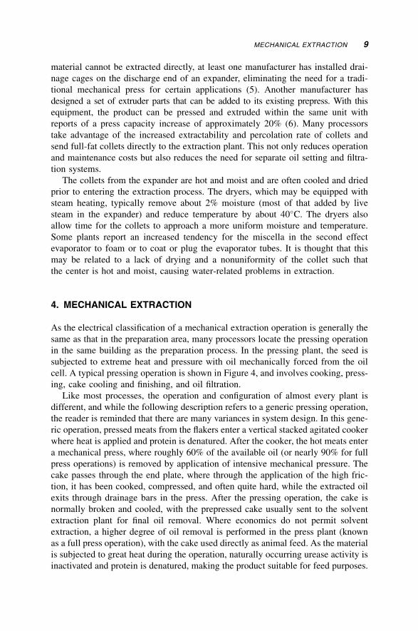
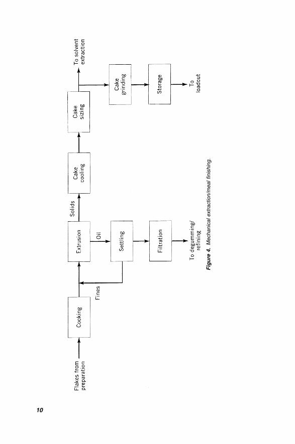
cell. A typical pressing operation is shown in Figure 4, and involves cooking, press-
ing, cake cooling and finishing, and oil filtration.
Like most processes, the operation and configuration of almost every plant is
different, and while the following description refers to a generic pressing operation,
the reader is reminded that there are many variances in system design. In this gene-
ric operation, pressed meats from the flakers enter a vertical stacked agitated cooker
where heat is applied and protein is denatured. After the cooker, the hot meats enter
a mechanical press, where roughly 60% of the available oil (or nearly 90% for full
press operations) is removed by application of intensive mechanical pressure. The
cake passes through the end plate, where through the application of the high fric-
tion, it has been cooked, compressed, and often quite hard, while the extracted oil
exits through drainage bars in the press. After the pressing operation, the cake is
normally broken and cooled, with the prepressed cake usually sent to the solvent
extraction plant for final oil removal. Where economics do not permit solvent
extraction, a higher degree of oil removal is performed in the press plant (known
as a full press operation), with the cake used directly as animal feed. As the material
is subjected to great heat during the operation, naturally occurring urease activity is
inactivated and protein is denatured, making the product suitable for feed purposes.
MECHANICAL EXTRACTION 9
Fig
ure
4.
Mechanic
alextr
act
ion/m
ealfinis
hin
g.
10
Oil from a mechanical pressing operation usually contains a high concentration of
meal fines, which are removed in a screening tank followed by a pressure leaf or
plate and frame filter, prior to delivering the crude oil to the refining process. The
quality of this oil may be higher than that obtained from solvent extraction, as less
oil-soluble impurities (such as phosphatides, etc.) are removed. In fact, oil from
some pressing operations (such as olive or evening primrose) is suitable for direct
consumption without additional processing. Removed fines are collected and typi-
cally recycled back to the press inlet.
A great number of variations may be used in the pressing operation. As indicated
earlier, expanders may be used either before the press or, in some instances, after
the press to agglomerate fines and provide consistency to the solvent extraction
operation. Material entering the cooker may be flaked, as indicated above, or
may be rolled seed with flaking operations taking place on the cake after the press.
5. SOLVENT EXTRACTION
After leaving the preparation process, the flakes (or collets) are delivered to the sol-
vent extraction operation. As this process typically uses a flammable solvent (and is
classified as a hazardous flammable environment), the operation is usually some-
what removed from other facilities, and access to the controlled area is restricted.
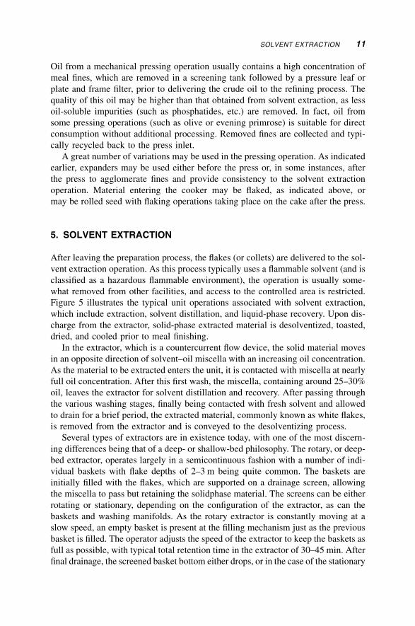
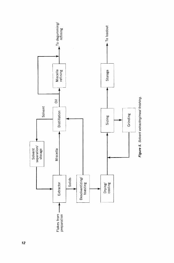
Figure 5 illustrates the typical unit operations associated with solvent extraction,
which include extraction, solvent distillation, and liquid-phase recovery. Upon dis-
charge from the extractor, solid-phase extracted material is desolventized, toasted,
dried, and cooled prior to meal finishing.
In the extractor, which is a countercurrent flow device, the solid material moves
in an opposite direction of solvent–oil miscella with an increasing oil concentration.
As the material to be extracted enters the unit, it is contacted with miscella at nearly
full oil concentration. After this first wash, the miscella, containing around 25–30%
oil, leaves the extractor for solvent distillation and recovery. After passing through
the various washing stages, finally being contacted with fresh solvent and allowed
to drain for a brief period, the extracted material, commonly known as white flakes,
is removed from the extractor and is conveyed to the desolventizing process.
Several types of extractors are in existence today, with one of the most discern-
ing differences being that of a deep- or shallow-bed philosophy. The rotary, or deep-
bed extractor, operates largely in a semicontinuous fashion with a number of indi-
vidual baskets with flake depths of 2–3 m being quite common. The baskets are
initially filled with the flakes, which are supported on a drainage screen, allowing
the miscella to pass but retaining the solidphase material. The screens can be either
rotating or stationary, depending on the configuration of the extractor, as can the
baskets and washing manifolds. As the rotary extractor is constantly moving at a
slow speed, an empty basket is present at the filling mechanism just as the previous
basket is filled. The operator adjusts the speed of the extractor to keep the baskets as
full as possible, with typical total retention time in the extractor of 30–45 min. After
final drainage, the screened basket bottom either drops, or in the case of the stationary
SOLVENT EXTRACTION 11
Fig
ure
5.
Solv
ent
extr
acting/m
ealfinis
hin
g.
12
basket bottom design, has an opening strategically placed to allow the solid phase to
discharge. As the extracted material drops, the screen is closed, and the cycle begins
anew. Extracted material is kept in a discharge hopper prior to conveying to the
desolventizing equipment. In this manner, a continuous flow is provided to down-
stream equipment while the plug of material in the hopper helps prevent the
possibility of desolventizer-toaster (DT) sparge steam from entering the extractor.
Shallow-bed extractors, with bed depths generally less than 1 m, provide similar
drainage screens in the form of slotted bars. The oil-bearing material is continuously
conveyed through zones in the extractor where the countercurrent washing of mis-
cella occurs. At the discharge end of the extractor the white flake material is
dropped into a hopper and is conveyed to the desolventizing system. Shallow-bed
extractors have gained significant popularity in recent years and, as they lend them-
selves very well to automated control, are well suited for modern programmable
logic control (PLC)-based operations.
Temperature control is extremely important during the extraction process. As
extractibility is enhanced with high temperatures, the operator generally desires
to keep temperatures as high as possible without flashing the solvent or creating
excess pressure in the extractor. However, phospholiapase enzyme activity affects
the oil quality at these elevated temperature conditions, partially causing an increase
in nonhydratable phosphatides. While this trade-off is generally not a problem,
when processing field-damaged seed it may be necessary to reduce extraction tem-
perature, sacrificing residual fats somewhat, in order to produce an oil that can be
acceptably processed without undue refining losses. As mentioned earlier, several
processes have been developed to help inactive enzyme activity prior to extraction.
While hexane is widely accepted as the most effective solvent used today, there
are concerns about its flammability, exposure, and environmental impacts. Research
has focused on various alternative solvents in the hopes of finding one with accep-
table performance while providing greater safety. Alternative solvents that have
received some attention include isopropyl alcohol, supercritical carbon dioxide,
and other fluids. However, no economical alternative to n-hexane has been accepted
at this point, and the best available control technology emphasizes containment and
limiting fugitive hexane emissions.
The extracted white flake material, containing around 25–35% residual solvent,
is conveyed from the extractor to the DT. In the traditional system; steam is used to
countercurrently flash the volatile solvent from the solid phase. The vapor phase
then passes through the distillation system on its way to condensing and collection.
The desolventized meal contains a high amount of urease activity (measured as a
pH rise) that is detrimental for certain animal feeding purposes. Under conditions of
heat, moisture, and retention time this enzyme is inactivated, and these variables
provide the basis of control for the DT operation. After the desolventizing section,
the solid-phase material passes through a series of steam-jacketed heating trays that
provide the environment necessary for toasting.
The DT is one of the largest single energy users in the solvent extraction opera-
tion. The desolventizing process is also responsible for the bulk of solvent sepa-
ration and recovery. As much of the DT steam is sparged in direct contact with
SOLVENT EXTRACTION 13
the meal, with the condensate not recoverable, much attention has been focused on
the efficiencies and economies of this unit operation. New technology has been
developed to minimize the amount of sparge steam and provide greater countercur-
rent contacting of the vapors with the meal. One extremely popular concept is the
Schumacher DT, which provides true counterflow contact of the vapor and solid
streams. Rather than perform desolventizing exclusively in the top section of the
DT, the counterflow design allows maximum effective vapor contact with the mate-
rial throughout the unit. Recent modifications to the counterflow DT have included
addition of pre-desolventizing steam-heated surfaces prior to the DT inlet as an
inexpensive way to improve the dry heat-sparge steam ratio.
After the traditional DT, the meal may contain in excess of 18% moisture and
may be 100�C or hotter. As trading rules and practical handling conditions do
not allow for these types of conditions, the meal must be dried and cooled prior
to storage and loadout. Traditional drying methods have utilized a slowly rotating
steam-tubed kilnlike dryer or other device with forced aeration to reduce the mois-
ture to proper storage levels. After drying the meal still contains excessive heat,
which is removed by another rotary kiln where cooling takes place either through
indirect contact with cooling water or by exposure to large amounts of air. Not only
is this equipment energy and maintenance intensive but introduces a number of
environmental problems with particulate emissions even with high-efficiency
cyclones. Wet scrubbing equipment has been introduced on some airstreams to col-
lect much of the fugitive emissions, but the resulting high biological oxygen
demand (BOD) loads in the scrubber effluent must be dealt with in an environmen-
tally acceptable manner. Quite often this effluent is introduced into the plant meal
or mill feed stream for moisture correction prior to loadout.
Using the same concept as the counterflow DT, the integrated dryer-cooler (DC)
reduces energy consumption and combines functions into a single vertical stacked
unit. Toasted hot meal enters the dryer section, where hot air is passed counterflow
through the meal bed, removing excess moisture. The meal then passes through the
cooler section, where the temperature is reduced by a countercurrent fresh airflow.
The DT and DC functions can be further integrated in a single vessel (DTDC), not
only reducing space and initial capital requirements but energy and operating costs
as well.
Of obvious concern in any DT application is the potential for overtoasting the
meal and adversely affecting the water solubility of the protein, often expressed
in terms of the protein dispersion index, or PDI. For certain edible flour and other
applications demanding a high PDI, the DTDC process may be replaced with a flash
desolventizing system. These systems, which typically use superheated solvent to
evaporate volatiles present in the freshly extracted white flakes, maintain the high
PDI while desolventizing the feedstock.
After cooling, the meal is screened to separate large particles from those of
acceptable size. This screener is typically either a multilayered inclined reciprocat-
ing bed screener or based around a continuously brushed cylindrical screen. Large
meal particles (or balls) are ground in a hammer mill and resifted prior to being
blended back into the meal stream. At this point, it is common to add mill feed,
14 A PRIMER ON OILS PROCESSING TECHNOLOGY
the mixture of hulls and other materials removed earlier in the process and a flow-
ability agent, such as calcium carbonate prior to storage. Meal storage can be pro-
vided by placement either in concrete or steel tanks and silos or, for longer storage
period, a flat storage facility. It is important that meal placed in storage be low in
moisture and well cooled. It is common practice to limit silo storage to 2–3 days,
but longer storage periods have proven acceptable with occasional meal transfer, or
‘‘turning.’’ As the meal is loaded into customer transport, it is common to add water
for moisture adjustment. For certain markets, the meal is passed through a pellet
mill directly after the meal dryer. This not only increases the bulk density of the
material, allowing for lower shipping costs, but also eliminates the grinding and
sizing operations. Belt dryers are normally installed after the pellet mills to cool
the product for storage and shipping.
Upon exiting the extractor, the miscella is passed through a series of distillation
equipment to separate the oil and recover the solvent. The process usually involves
a series of falling film evaporators and stills with the miscella on the tube side and
vapors on the shell side. The first effect evaporator, using steam and solvent vapors
liberated from the DT, concentrate the miscella from around 28% up to 80% or
higher. The liberated vapors are condensed, sent to the work tank for water–solvent
separation with the solvent reintroduced into the extractor. The miscella then passes
to the second-stage evaporator, typically operating at atmospheric or vacuum con-
ditions, where the miscella concentration is increased up to 95–98% oil. Finally, the
miscella enters the oil stripper or still, which, operating at 50 mm Hg abs or less,
removes most of the remaining volatiles. The oil typically leaves the extraction plant
at this stage with moisture and volatiles (M&V) less than 0.15% or passes through a
second oil dryer or ‘‘superstripper’’ to obtain a very low M&V oil. The oil is then
cooled and sent to storage. It is extremely important to minimize moisture levels in
the final oil, as phosphatides have a great affinity for residual moisture and will
separate as gums from the crude oil in the presence of moisture. In fact, one pro-
cessor considered introducing water in the oil leaving the processing facility and
using its long-term storage tanks essentially as batch degumming vessels, decanting
the top phase as degummed oil. In practice, this plan was rejected, as the heavy
phase gums can be quite difficult to remove from transport vessels and storage
tanks, and excessive deposition may result in rejection of an oil shipment. Moisture
retained in crude oil can also increase the free fatty acids (FFA), and corresponding
neutral oil loss, under certain storage conditions.
Miscella refining of some oils, especially cottonseed, has gained great popularity
in recent years. In this process, caustic is added to the half miscella between the first
and second effect evaporator, and the mix is subjected to centrifugation separation.
The refined light-phase miscella continues on to the distillation system while the
heavy-phase soapstock is blended back in the meal stream in the DT. Although
there is a legitimate concern about locating high-speed centrifugal equipment in
a hazardous environment, there are substantial benefits to be considered. A major
advantage, especially with cottonseed, is that color bodies are removed before they
are ‘‘set’’ in the oil by exposure to high-temperature distillation equipment. Not
only is the oil of excellent quality, but refining losses are considerably lower
SOLVENT EXTRACTION 15
than the traditional methods. Other advantages include elimination of the water
washing system, and a convenient disposal means for the soapstock. While the mis-
cella refining typically requires a half miscella concentration of about 60% oil, with
a resulting higher hydraulic load through the centrifuge, the difference in specific
gravity between the two phases is substantial, allowing very high capacity through
the centrifuge. Additional miscella processing has been practiced, including miscel-
la bleaching and fractionation.
6. DEGUMMING, LECITHIN PROCESSING, AND PHYSICALREFINING PRETREATMENT
A solvent extraction free, caustic refining free process for producing refined soy-
bean oil has been described (7). Oils high in phosphorus, such as soybean, corn,
and sunflower, may be degummed prior to refining. Degumming may be considered
the first step in the refining process, especially for processors with an integral gums
disposal option, and is designed to remove the phosphatides that interfere with sub-
sequent processing. The degumming process is not a mandatory process, as the
phosphatides can generally be effectively removed in subsequent processes. In
fact, some processors prefer to refine crude oil than crude-degummed oil as a better
‘‘break’’ is obtained in some older style centrifuges (8). This may be especially
applicable for solid bowl machines where an additional amount of ‘‘bowl flush’’
water is injected with the feedstock to facilitate removal of the heavy-phase mate-
rial. Addition of this bowl flush not only increases potential refining losses but
represents an additional hydraulic load on the plant acidulation system. With the
advent of self-cleaning centrifuges, this bowl flush is not as critical, and coupled
with increasing environmental concerns associated with soapstock utilization, the
preference for crude over degummed oils may shift.
The fact remains that today the primary reasons for degumming are to either pro-
vide a crude-degummed oil suitable for storage or long transit, to prepare oil for
physical refining, or to produce lecithin. Processing degummed oil does provide
a side benefit for the stand-alone refiner lacking a lecithin disposal option. Phospho-
lipids are an excellent emulsifier (which explains much of the demand for lecithin)
and, when discharged as soapstock, introduce problems for oil–water separation
in the acidulation process. Processors who experience problems meeting water
effluent limitation without extensive waste treatment costs may be forced to specify
degummed feedstock for this reason alone.
Traditional water degumming is effective only for water-hydratable phosphatides,
those having a greater affinity for a water phase existence than remaining in the oil
phase. However, significant amounts of nonhydratable phosphatides (NHP) exist that
cannot be effectively removed without special treatments. The presence of signi-
ficant quantities of NHP usually indicates a poor-quality oil, for soybean oil
from fresh good-quality beans about 90% of the phosphatides are normally hydra-
table. However, when seed is severely damaged, the hydratable phosphatide may be
reduced by as much as 50% over time (9).
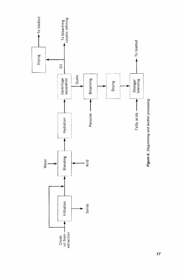
Figure 6 illustrates a typical degumming operation integrated with lecithin pro-
cessing. If lecithin is produced for edible purposes, the crude oil is first filtered to
16 A PRIMER ON OILS PROCESSING TECHNOLOGY
Fig
ure
6.
Degum
min
gand
lecithin
pro
cessin
g.
17
remove meal fines and other insoluble impurities. For straight degumming purposes
(without lecithin production), the fines from a well-maintained facility are generally
not a major problem for centrifugal removal. The oil continues to hydration, where
a rationed amount of softened water is added to the oil, intimately mixed, and then
introduced in a gently agitated hydration tank. During this retention period, the
gums agglomerate and begin to separate from the oil phase. The mixture is then
gently delivered to the centrifuges, with the light-phase oil passed through the mois-
ture dryer, cooled, and finally delivered to storage.
When not used as lecithin, the heavy-phase gums can be reintroduced into the
meal stream through the DT, adding energy to the meal and assisting with dust
control. When sold as non-food-grade lecithin, the gums are simply dried from
35 to 50% moisture concentration and used either as a plastic, high-AI (acetone-
insoluble) product, or blended with either degummed oil or distilled fatty acids
for consumption as a fluid product. Gums used for food-grade lecithin may require
color correction and after separation in the centrifuge are generally single bleached
(using hydrogen peroxide) or double bleached (using benzoyl peroxide) in an
agitated retention vessel. Bleaching agents can also be introduced in the oil hydra-
tion tank. It should be noted there have been concerns expressed about decompo-
sition products associated with these bleaching agents, especially benzoyl peroxide,
which prohibit their use for certain markets. After reaction with the bleaching
agent, the phosphatides are introduced into the gums dryer. Divalent metals can
also be introduced at this point to improve flowability. The dryer, which generally
consists of a vertical or horizontal wiped film evaporator operating at less than
50 mm Hg abs, uses carefully controlled steam jacket heating to evaporate the
moisture in the hydrated gums. After leaving the dryer, the lecithin is slightly
cooled, and depending on the quality of the product, may be sold as plastic product
(AI > 65%) or blended with degummed or refined oil, and sold as a fluid product.
Oil or distilled fatty acids may be added to reduce the viscosity and increase the
lecithin acid value. Special attention must be paid to the design of the lecithin
storage and handling system as the products are very viscous and potentially
hard to handle. Storage tanks and lines are generally jacketed with low-pressure
steam or hot water to ensure flowability without overheating and darkening of
the product. Lecithin is usually sold in drums, pails, or truckload lots.
Production of a clear and sparkling lecithin product is highly vulnerable to effects
caused by upstream conditions. Field- or storage-damaged beans can result in a
cloudy, dark lecithin that may be unacceptable for use as edible product. The quality
is also highly affected by grain drying, conditioning, extraction, and oil distillation
temperatures and exposure times. Lecithin periodically seems to develop a cloudy
haze, which is extremely difficult to remove using traditional methods. It is postu-
lated that this haze is a form of sugar, starch, or other material extracted from the
oilseed. Lecithin from plants using expanders seem to experience this phenomenon
more frequently, possibly related to greater extractability of collets.
Lecithin may also be deoiled and sold as a granulated product high in phospha-
tyol choline. This process typically involves an acetone extraction, leaving a
granulated product for packaging.
18 A PRIMER ON OILS PROCESSING TECHNOLOGY
When the production of lecithin is an objective of degumming, maximum removal
of phosphatides from the crude oil becomes a primary concern. It is interesting to
note that a significant economic benefit is provided by producing lecithin, not only
because of manufacture of an added-value product but also because of its impact on
the meal. In a protein control meal situation, approximately 1.25 kg of mill feed can
be added for every kilogram of gums diverted from the meal stream. This is due to
the protein content of mill feed and may provide as much of the justification of a
lecithin production operation as the increased value of the lecithin itself. The effect
of producing lecithin is negative, however, in a fiber control situation. When
lecithin is not produced as part of a degumming operation, then a controlling factor
usually becomes the maximum level of phosphorus permitted in the degummed
product. Generally the processor has little trouble removing sufficient gums to meet
the trading rules limits, as most of the gums are water hydratable. There are times
when simple water degumming is not sufficient as there are, as indicated earlier,
several factors that affect the amount of nonhydratable phosphatides in the crude
oil. In addition, physical refining continues to gain popularity, and the degumming
system is called upon to produce a lower phosphatide oil than normally possible
with a traditional water hydration system. These factors have resulted in consider-
able new approaches for more complete phosphatide removal in the degumming
operation. Lecithin recovered from solvent extracted soybean oil had different
phospholipid class compositions from those produced by mechanical pressing (10).
Several acid treatment and other processes have gained acceptance in producing
a lower phosphorous degummed oil. These processes, including Unilever’s super
degumming, the TOP process, total degumming, and others, focus on the fact that
calcium, magnesium, and iron salts of phosphatidic acid have a greater affinity for
the oil phase than the water phase and as such must be removed from the oil by
a special process. Pretreatment of oil with phosphoric acid, citric acid, or another
agent with proper temperature, time, and agitation conditions, followed by a water
hydration as described above, is generally effective in removing phosphatide con-
taining components. Silica absorption processes are also effective in precipitating
these phosphatides. Use of these pretreatment systems can produce a degummed
oil that when properly bleached will have phosphorous levels less than 3 ppm,
although these processes are generally not as flexible or ‘‘forgiving’’ as a traditional
alkali refining process. Oil of this quality is generally acceptable feedstock for phy-
sical refining, which is discussed later in this Chapter.
As acid degumming has proven to be cost effective, many variations have been
developed to improve the consistency of its results. One method, especially deve-
loped for canola, suggests introduction of a small amount of dilute caustic after
acid pretreatment immediately prior to the degumming centrifuge. The system is
said to produce an oil of equal quality to caustic refined oil without the problems
of soap generation and requirement for subsequent water washing (5). While super-
degumming systems do have advantages both in terms of capital and operating cost
reductions, the impact on the gums must be considered. The lecithin resulting
from an acid pretreatment system is usually darkened in color and generally consi-
dered unsuitable for edible purposes. Wet gums from an acid-treated degumming
DEGUMMING, LECITHIN PROCESSING, AND PHYSICAL REFINING PRETREATMENT 19
system should be neutralized before introduction into the meal stream. Finally, as
many degumming and lecithin processing installations are located in the extraction
plant, there is concern about the safety of storing the acid (and peroxides for
lecithin) in an environment containing flammable solvents.
While the concept of wet degumming usually involves the processes described
above, there is an alternate process called dry degumming (as pretreatment for phy-
sical refining) for lower phosphatide oils, such as coconut. This process is usually
integrated into the bleaching operation and involves introduction of acid, usually
phosphoric, with either a brief retention high temperature, high shear retention,
or a longer retention lower temperature, less vigorous agitation system. The acid
and precipitated phosphatides are removed in the subsequent bleaching operation.
While the continuous degumming operation has become the standard for most
operations, some older and specialty processors practice batch degumming. This
operation, which is frequently combined in a single vessel performing sequential
degumming, neutralization, and bleaching, involves hydration, settling, and decant-
ing the degummed oil from the gums. While initial capital costs of batch operations
may be less than a continuous process, the operating costs of labor, chemicals, and
neutral oil loss make batch processing unfeasible for all but the smallest operations.
Degumming is an integral part of the physical refining operation, which will
see continued growth in response to environmental pressures. While the basics of
the degumming process have been largely unchanged for several years, new mem-
brane separation systems have been gaining recent attention (11). Past problems of
plugging may be solved by new filter media, miscella filtration, or evolution of self-
cleaning designs.
7. CAUSTIC REFINING
Refining is the term liberally applied to the processes designed to neutralize free
fatty acids present in the oil by introduction of an alkali and centrifugal separation
of the heavy-phase insoluble material. Refining is also associated with removal of
phospholipids, color bodies, and other soluble and insoluble impurities. The term
refining can be applied to physical and chemical operations, as they both are
designed to perform much of the same tasks. As physical refining operations are
generally incorporated into degumming, bleaching, and deodorizing systems (also
known as steam refining systems), descriptions of these processes are integrated
into discussions of these areas. Miscella refining shares many similarities with
chemical refining but has specific considerations as described in the extraction
section of this Chapter. The focus of this section will be on the chemical, or alkali,
refining process.
Caustic refining in particular does not only effectively perform the separation
functions described above but is considered ‘‘more forgiving’’ in operation than
alternate physical methods. If the degumming operation has been less than perfect
(or is not used), alkali refining will remove the bulk of the phosphatides. If a high
amount of metals, particularly calcium and magnesium, are present, these can be
20 A PRIMER ON OILS PROCESSING TECHNOLOGY
removed in the chemical neutralization process. Caustic refining is also less sensi-
tive to the type of feedstock presented, as a system designed for one oil will gene-
rally produce satisfactory results with other oils. Caustic refining does have its
substantial downfalls, however, which have led to development of the alternate pro-
cesses, such as physical or steam refining.
If degumming is not included, caustic neutralization is the traditional first step
for edible oil processing. It is important to remove the impurities at this stage of
processing as the oil when heated in subsequent steps may turn dark, smoke and
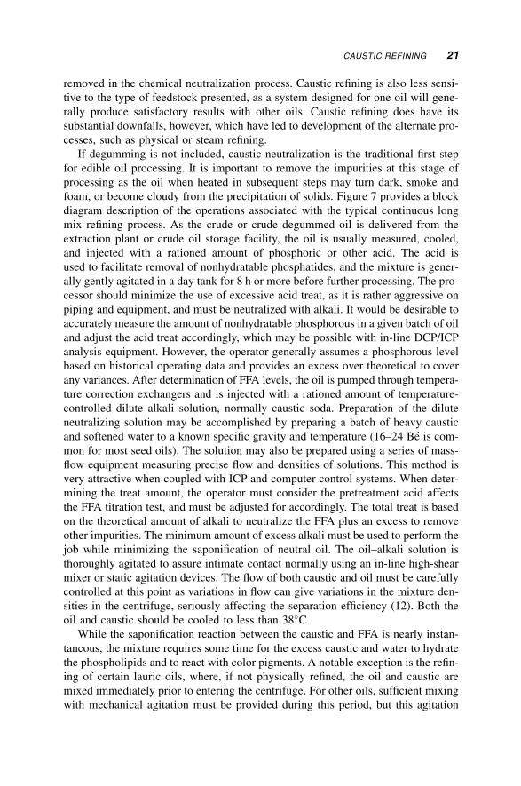
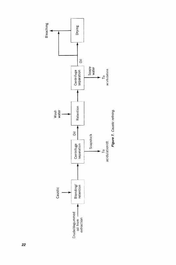
foam, or become cloudy from the precipitation of solids. Figure 7 provides a block
diagram description of the operations associated with the typical continuous long
mix refining process. As the crude or crude degummed oil is delivered from the
extraction plant or crude oil storage facility, the oil is usually measured, cooled,
and injected with a rationed amount of phosphoric or other acid. The acid is
used to facilitate removal of nonhydratable phosphatides, and the mixture is gener-
ally gently agitated in a day tank for 8 h or more before further processing. The pro-
cessor should minimize the use of excessive acid treat, as it is rather aggressive on
piping and equipment, and must be neutralized with alkali. It would be desirable to
accurately measure the amount of nonhydratable phosphorous in a given batch of oil
and adjust the acid treat accordingly, which may be possible with in-line DCP/ICP
analysis equipment. However, the operator generally assumes a phosphorous level
based on historical operating data and provides an excess over theoretical to cover
any variances. After determination of FFA levels, the oil is pumped through tempera-
ture correction exchangers and is injected with a rationed amount of temperature-
controlled dilute alkali solution, normally caustic soda. Preparation of the dilute
neutralizing solution may be accomplished by preparing a batch of heavy caustic
and softened water to a known specific gravity and temperature (16–24 Be is com-
mon for most seed oils). The solution may also be prepared using a series of mass-
flow equipment measuring precise flow and densities of solutions. This method is
very attractive when coupled with ICP and computer control systems. When deter-
mining the treat amount, the operator must consider the pretreatment acid affects
the FFA titration test, and must be adjusted for accordingly. The total treat is based
on the theoretical amount of alkali to neutralize the FFA plus an excess to remove
other impurities. The minimum amount of excess alkali must be used to perform the
job while minimizing the saponification of neutral oil. The oil–alkali solution is
thoroughly agitated to assure intimate contact normally using an in-line high-shear
mixer or static agitation devices. The flow of both caustic and oil must be carefully
controlled at this point as variations in flow can give variations in the mixture den-
sities in the centrifuge, seriously affecting the separation efficiency (12). Both the
oil and caustic should be cooled to less than 38�C.
While the saponification reaction between the caustic and FFA is nearly instan-
tancous, the mixture requires some time for the excess caustic and water to hydrate
the phospholipids and to react with color pigments. A notable exception is the refin-
ing of certain lauric oils, where, if not physically refined, the oil and caustic are
mixed immediately prior to entering the centrifuge. For other oils, sufficient mixing
with mechanical agitation must be provided during this period, but this agitation
CAUSTIC REFINING 21
Fig
ure
7.
Caustic
refinin
g.
22
must not be sufficiently turbulent to create stable emulsions that will not separate in
the centrifuges. The proper retention period is usually provided by zoned mixers
that are generally multiple units provided in series for maximum flexibility in pro-
cessing. For example, while soybean oil may require 5 min or longer for the reac-
tion to be completed, less retention is beneficial for corn oil processing (13). After
leaving the retention mixers, the mixture is heated to reduce viscosity and to pro-
vide a more definite separation of the soap and the oil. While the optimum sepa-
ration temperature must be determined on an individual plant basis, practical
experience suggests that this heating duty is not a good application for an oil–oil
interchanger. While the energy balance between this service and the hot-water-
washed oil certainly looks favorable, it has been observed that separation efficiency
may suffer if the oil is not subjected to the high-temperature gradient provided
by steam. After the heater, the mixture enters the primary refining centrifuge.
Centrifuges are generally of the paring disk, hermetic or semihermetic type,
where changes of the zone of separation occur as the light-phase discharge back
pressure is adjusted. Increasing the back pressure reduces the soap content in the
oil phase but allows more neutral oil to exist with the soapstock, while decreasing
the back pressure has the opposite effect. The centrifuge operator generally sets the
proper back pressure by viewing a slight turbidity in the light-phase discharge sight
glass or tests for separation efficiency of the refined oil with a table-top separator.
While dramatic zone changes can be made by back pressure control in a hermetic
machine, more substantial changes in the separation zone may be made by chang-
ing the centripetal pump in the pressure-type centrifuge. Neutral oil in soapstock
should be 18% or less on a dry basis, while refined oil soaps in excess of 500 ppm
indicate back pressure should be increased. If soaps cannot be effectively reduced
through back pressure control, the centrifuge probably requires cleaning.
From the primary, the heavy-phase soapstock enters the acidulation system or,
in some instances, is introduced back into the meal stream. Care must be taken
with reuse of this material, as the high pH should be neutralized prior to livestock
feeding, and the high moisture and fat concentration will affect feed formulation.
The light-phase refined oil discharged from the centrifuge is generally heated,
mixed with 10–15% hot water and the mixture subjected to an intimate mixing.
To maximize the adsorption of soaps, the oil–water mixture should pass through
another retention zone mixer, again with sufficient but gentle agitation to avoid
emulsification. In some facilities, a water-wash holding tank is provided for this
retention period. This tank is not only designed to provide proper mixing and
residence time but allows a ‘‘wide spot in the road’’ to avoid affecting the line
when the primary centrifuge ‘‘shoots’’ or otherwise disrupts product flow. Phos-
phoric acid can be added in the washwater to reduce the residual soap in the refined
oil, and to provide a better split between the oil and aqueous phase. While common
in double-wash systems, it is thought that at least a portion of the water from a
single-wash system can be reused, not only reducing hydraulic loading on the waste
treatment plant but also maximizing thermal efficiency. At least one processor
uses a portion of this soapy water for bowl flush water. For optimum soap removal,
the oil–water mixture is heated before entering the waterwash centrifuge. This
CAUSTIC REFINING 23
centrifuge generally reduces the residual soap by a factor of 10:1, with soap con-
centration in the oil typically less than 50 ppm. After the washing machine, the oil
may be sent to the vacuum dryer, where the residual 0.5% moisture is removed.
With some designs, an oil dryer may not be provided, as residual moisture enhances
absorption efficiency of the certain bleaching agents. Special care must be taken
when storing this wet oil, although most of the natural preservatives are still present
at this point of processing. At a minimum, the oil is cooled prior to storage, and
some installations may begin nitrogen blanketing at this point.
As indicated earlier, the long mix system requires a certain residence time to
allow the caustic to react with certain components in the oil. This system, which
has been the standard in the United States for years, is especially well suited for
removal of gossypol from cottonseed oil and phosphatides from soybean oil.
This system is quite common in large refineries with few stock changes per day.
In Europe and developing countries, the move toward larger, continuous plants
took longer, and the short mix system was developed to provide greater flexibility
and stock change ability. In this process, the zone mixers are generally not used,
pretreatment agents are introduced into hot oil, and the hot oil and caustic are inti-
mately blended in a high-shear mixer and immediately introduced into the primary
centrifuge. The advantage of longer retention times during the reaction between oil
and caustic are becoming more apparent to many seed oil processors. The long mix
system is therefore gaining ground with many traditional short mix processors,
especially those working with soybean and canola oil (5). It is also common prac-
tice in some of these facilities to provide a double water washing, with the water
phase discharge of the second centrifuge used for makeup water for the first
washing machine. While this does represent a potential savings in water consump-
tion, this practice has generally not been adapted in the United States, as the soaps
from the primary centrifuge tend to be lower and may be more easily reduced than
with the short mix operation (5).
Modern refining usually involves the continuous operation with centrifugal sepa-
ration as described above. Refining originally evolved from batch operations, which
are still used in some small and specialty operations, and involve much of the same
process techniques with separation of the heavy phase performed by settling and
draining in the vessel. One serious problem, especially with nondegummed oils,
is the creation of the stable emulsion layer. It is common to add a brine and other
solutions as part of the batch process to help break this emulsion, and a double
(or triple) washing is also common. As one may expect, batch refining is highly
labor intensive, introduces significant environmental problems, requires several
hours to process a batch, and incurs significant losses. For these reasons even small
specialty processors are encouraged to consider continuous refining operations.
An interesting trend in alkali refining is adaptation of acid refining operations.
One design optimized for canola introduces acid into the oil through a zone mixer
immediately prior to caustic addition and a second zone mixer. This system is said
to significantly reduce the refining loss and improve the color. Another interesting
trend is close integration of refining with the bleaching operation. As indicated
earlier, it is now common practice to eliminate the refined oil dryer, leaving the
24 A PRIMER ON OILS PROCESSING TECHNOLOGY
residual moisture in the oil to enhance bleaching. A further development is the
elimination of the water wash step, using instead hydrated silica or other materials
to adsorb the soaps and residual phosphorus during bleaching. This topic is covered
more fully in the bleaching section of this Chapter.
Chemical refining is responsible for a great amount of processing loss (and
resulting environmental problems) associated with oilseed processing. For that
reason, a great deal of emphasis has been placed on automation and loss monitoring
of the process streams. On-line instrumentation to determine FFA, phosphorus,
and other process parameters is becoming increasingly feasible. DCP/ICP instru-
mentation, which although expensive, may prove to be justifiable with improved
process control. To date, most control efforts have focused on loss monitoring,
measuring the flows of crude, refined, and washed oil, and controlling the corres-
ponding acid, caustic, and water flow addition rates with mass flow devices. Once
acceptable loses have been established, the operator is notified if upset conditions
are encountered.
While physical refining will continue to receive attention, alkali refining is likely
to continue to be the preferred choice where soapstock disposal issues can be re-
solved economically. Unlike some physical refining systems, alkali refining allows
the processor to properly prepare almost any type (and any condition) of oil to pro-
duce a quality product. Alkali refining introduces its special set of maintenance,
environmental, and neutral oil loss issues for which the processor must continually
be alert.
8. BLEACHING
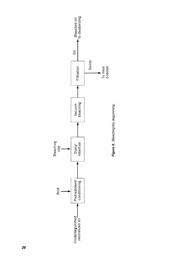
Bleaching is the term given to describe the adsorptive cleansing process associated
with edible oil refining. This process, as shown in Figure 8, may involve acid pre-
treatment, introduction of and a retention period with a bleaching agent, and
removal of the clay and absorbed materials. While the mechanical process is on
the surface rather simple, the importance of the bleaching operation commands
significant attention.
Bleaching plants have evolved from open batch systems to continuous proces-
sing operations with alternating filters used for clay removal. In practice, oil to be
bleached may be pretreated with acid (known as the dry degumming process for
crude oils), and after a sufficient residence period, the oil may be dosed with the
clay and other agents in a slurry tank. The materials may be introduced in a slip-
stream of the oil with the slurry immediately directed back to the main flow of oil or
may be introduced in a tank designed to hold the entire flow of oil under nitrogen-
blanketed conditions for several minutes. Other materials may also be introduced at
this point, such as activated carbon for canola and other oils and filter aids. After
leaving the slurry system and prior to entering the bleacher, the oil may be heated to
bleaching temperature. Under vacuum conditions, the oil is agitated in the compart-
mentalized bleacher for several minutes and then delivered to one of two bleaching
filters for removal of solid materials. While plate and frame filters may be used for
BLEACHING 25
Fig
ure
8.
Ble
achin
g/d
rydegum
min
g.
26
some applications, the pressure leaf filter is by far the preferred choice for modern
installations. The filters are available in either a vertical or horizontal configuration,
depending on plant preference, and can be fully automated by using a plant PLC
system. During the filtration cycle, as a filter becomes full, as indicated by an
increasing pressure differential between the feed and discharge streams, the filter
is taken off-line for cleaning while the alternate filter is brought on-line. After
removing the residual oil from the filter cake (normally using steam and nitrogen),
removing the cake from the filter screens is accomplished by vibrating the screens.
A horizontal filter with cake discharge by leaf rotation was introduced several years
ago. This design has the advantage of a lower space requirement for bundle with-
drawal and has a reported higher cake retention and lower residual oil. However,
the drawbacks of higher mechanical complexity and costs may be limiting factors.
Regardless of the filter type, the filtered bleached oil passes through a polish filter
to remove any traces of solids, and is then cooled prior to storage. As many of the
natural antioxidants are removed during bleaching, many processors elect to nitro-
gen blanket the oil after the bleaching process.
Several modifications to traditional bleaching plant designs have been intro-
duced in recent years. Steam agitation has been used as an alternative to mechanical
agitation and bleaching materials have been introduced directly into bleaching
vessels without preslurrying the oil in a separate slurry vessel. One interesting con-
cept is to eliminate the traditional retention bleacher, and provide retention time for
the clay–oil slurry through a series of specially designed pipes. After the retention
period a flash vessel is used to drive off moisture in the oil prior to filtration.
Another recent development is introduction of a new filter screen, which is said
to have a longer life and eliminate the need for diatomaceous earth precoating (5).
While the degumming operation is designed to remove phosphatides and the
caustic refinery converts the soluble free fatty acids to insoluble soaps, adsorptive
bleaching provides the processor the last practical opportunity to remove remaining
impurities to acceptable levels. While the traditional control for bleaching has been
color reduction, the modern processor does not simply use the Lovibond scale to
determine the effectiveness of the bleaching operation. While color correction is
an important consideration, modern bleaching operations provide even greater
benefits.
In addition to modifications to equipment and designs, development of adsorb-
ents and modification of processes to optimize the adsorption has received consi-
derable attention. As indicated earlier, color reduction was the traditional indication
of the effectiveness of the bleaching operation. The major color pigments in edible
oil are chlorophyll (green) and carotenoids (orange) and while chlorophyll must
be reduced in the bleaching process, carotenoids can be reduced in later processes.
For high-chlorophyll seeds, such as canola, bleaching clay dosing is quite heavy
and is sometimes augmented by the addition of activated carbon or other agents.
Carotenoid elimination typically occurs in hydrogenation and deodorizing, some-
times called the heat bleach effect. While color correction is certainly important,
bleaching provides the last opportunity to remove remaining phospholipids. Not
only must phosphatides be minimized for proper deodorizing, but these also affect
BLEACHING 27
hydrogenation selectivity and activity at levels down to 4 ppm (14). Residual soaps
created in caustic neutralization should also be removed by the bleaching adsorp-
tion process. Not only can these soaps cause polymerization in the deodorizer,
affecting not only operation but quality of the oil, but they can also interfere with
hydrogenation (15). Products of oxidation, both primary (peroxide value) and
especially secondary (anisidine value), should also be removed during bleaching
to provide a suitable shelf life oil. Finally, trace metals, especially iron and copper,
should also be removed in the bleaching process. While citric acid chelation in the
deodorizing process will help inactivate the catalytic oxidative tendency of these
metals, it is more desirable to remove them as early as possible in the process.
Clearly, while color is an important indicator of bleaching effectiveness (and is easy
to check), residual soaps, phosphorus, peroxide, and anisidine values are also some
key quality indicators associated with the bleaching process.
As an enhancement to bleaching efficiency, silica gel is commonly added to
remove soaps and phospholipids before exposing the oil to bleaching clay. In prac-
tice, the clay normally slurried continuously with the oil is applied on the filter
leaves immediately after precoating. The silica gel is continuously added in the
body feed slurry system and is especially effective when contacting the oil at atmo-
spheric conditions with residual moisture from the water washing step. As indicated
earlier, many processors do not use the refinery dryer, leaving the residual wash-
water moisture in the oil to enhance this effect. For dry degumming systems, water
is sometimes added with the pretreatment acid to increase the crude oil moisture
content. After reaction with the silica, the moisture is removed in the vacuum blea-
cher prior to exposure to the bleaching clay, which has been preloaded on the filters.
An interesting alternative to acid and alkali refining has been developed by W.R.
Grace & Co., using its silica gel product. As this material has a higher ability to
adsorb soap and phospholipids than traditional bleaching clays, it has been used
to eliminate the water washing step altogether. This not only reduces the capital
costs associated with refinery equipment but significantly eliminates hydraulic
load on the plant waste treatment operation. As an increased amount of silica is
required for this adsorption service, any savings must be balanced against the silica
cost and those associated with the increased cake oil loss, solid waste disposal, and
reduced filter cycle time. However, most processors find this economic balance
positive, and more activity in this field can be expected.
An unfortunate consideration associated with bleaching is the generation and
subsequent disposal of the spent cake. Not only does the residual oil in the cake
represent a loss to the processor, but spent cake is prone to spontaneous combustion
under certain conditions when exposed to air. For that reason, spent cake may be
classified as a hazardous material, making its environmentally responsible disposal
difficult. The traditional landfill option may be restricted, not only because of this
classification but also because of the limited space available at many locations.
Spent cake can be added to meal in some cases, but this practice is frowned upon,
especially when processing multiple types of oil. While deoiling the cake does help
reduce the risk of combustion (and work is underway to reuse some of this mater-
ial), most emphasis will be focused on alternate uses for the spent clay. Some
28 A PRIMER ON OILS PROCESSING TECHNOLOGY
concepts being explored include use as asphalt additive, replacement for plastic
parts in refractories, re-refining mineral oils, road foundation, soil stabilizers, and
lightweight aggregate applications (16).
9. DEWAXING
Dewaxing refers to the removal of high-melting-point ‘‘waxes’’ extracted from
certain oilseeds, such as corn, sunflower, and canola. While the wax usually does
not negatively affect the functionality of the products, the presence of wax affects
the appearance of the product. As products sold as salad oils are often packaged in
clear bottles, such as PVC or PET, a haze, and possibly a wax deposition, may form
over time when exposed to conditions of the modern supermarket. If refrigerated,
this effect will become more pronounced and the end user, not understanding
melting point characteristics, will assume the oil is of inferior quality. Conse-
quently, dewaxing has become a process tool in the integrated refinery where waxes
are removed by a chilling, settling, and separation process.
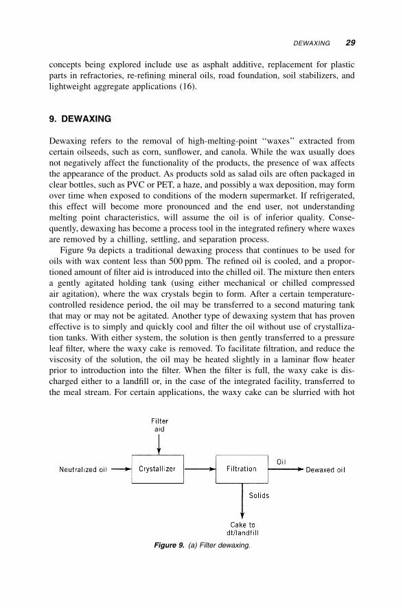
Figure 9a depicts a traditional dewaxing process that continues to be used for
oils with wax content less than 500 ppm. The refined oil is cooled, and a propor-
tioned amount of filter aid is introduced into the chilled oil. The mixture then enters
a gently agitated holding tank (using either mechanical or chilled compressed
air agitation), where the wax crystals begin to form. After a certain temperature-
controlled residence period, the oil may be transferred to a second maturing tank
that may or may not be agitated. Another type of dewaxing system that has proven
effective is to simply and quickly cool and filter the oil without use of crystalliza-
tion tanks. With either system, the solution is then gently transferred to a pressure
leaf filter, where the waxy cake is removed. To facilitate filtration, and reduce the
viscosity of the solution, the oil may be heated slightly in a laminar flow heater
prior to introduction into the filter. When the filter is full, the waxy cake is dis-
charged either to a landfill or, in the case of the integrated facility, transferred to
the meal stream. For certain applications, the waxy cake can be slurried with hot
Figure 9. (a) Filter dewaxing.
DEWAXING 29
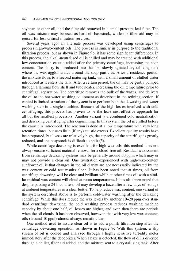
soybean or other oil, and the filter aid removed in a small pressure leaf filter. The
oil–wax mixture may be used as hard oil basestock, while the filter aid may be
reused for less critical filtration services.
Several years ago, an alternate process was developed using centrifuges to
process high-wax-content oils. The process is similar in purpose to the traditional
filtration process, but as shown in Figure 9b, it has some significant differences. In
this process, the alkali-neutralized oil is chilled and may be treated with additional
low-concentration caustic added after the primary centrifuge, increasing the soap
content. The slurry is introduced into the first slowly agitated crystallizing tank
where the wax agglomerates around the soap particles. After a residence period,
the mixture flows to a second maturing tank, with a small amount of chilled water
introduced as it enters the tank. After a certain period, the oil may be gently pumped
through a laminar flow shell and tube heater, increasing the oil temperature prior to
centrifugal separation. The centrifuge removes the bulk of the waxes, and delivers
the oil to the hot-water washing equipment as described in the refining section. If
capital is limited, a variant of the system is to perform both the dewaxing and water
washing step in a single machine. Because of the high losses involved with cold
centrifuging, this process has proven to be the least cost-effective approach for
all but the smallest processors. Another variant is a combined cold neutralization
and dewaxing centrifuging after degumming. In this system the oil is chilled before
the caustic is introduced. The reaction is done at a low temperature with very long
retention times, but uses little (if any) caustic excess. Excellent quality results have
been reported, but losses are relatively high, the capacity of the centrifuge is greatly
reduced, and the soapstock is difficult to split (5).
While centrifuge dewaxing is excellent for high-wax oils, this method does not
always ensure sufficient material removal for a cloud-free oil. Residual wax content
from centrifuge dewaxing systems may be generally around 50 ppm, which may or
may not provide a clear oil. One frustration experienced with high-wax-content
sunflower oil is that changes in the oil clarity are not necessarily indicated by the
wax content or cold test results alone. It has been noted that at times, oil from
centrifuge dewaxing will be clear and brilliant while at other times oil with a simi-
lar residual wax content will cloud at room temperatures. It has also been noted that
despite passing a 24-h cold test, oil may develop a haze after a few days of storage
at ambient temperatures in a clear bottle. To help reduce wax content, one variant of
the system described above is to perform cold-water washing after the dewaxing
centrifuge. While this does reduce the wax levels by another 10–20 ppm over stan-
dard centrifuge dewaxing, the cold washing process reduces washing machine
capacity by about one half, oil losses are higher, and even then there are periods
when the oil clouds. It has been observed, however, that with very low wax contents
oils (around 10 ppm) almost always remain clear.
One method used to assure clear oil is to add a polish filtration step after the
centrifuge dewaxing operation, as shown in Figure 9c With this system, a slip
stream of oil is cooled and analyzed through a highly sensitive turbidity meter
immediately after the deodorizer. When a haze is detected, the flow of oil is diverted
through a chiller, filter aid added, and the mixture sent to a crystallizing tank. After
30 A PRIMER ON OILS PROCESSING TECHNOLOGY
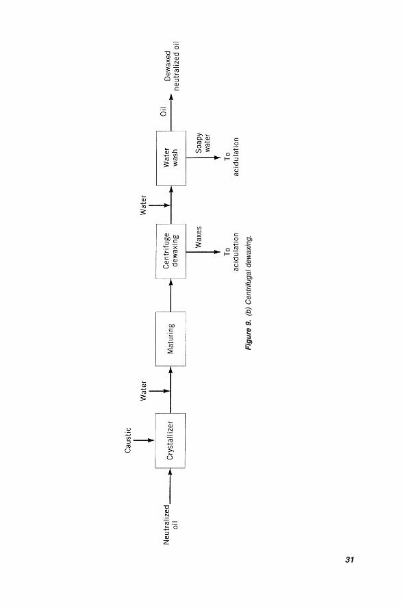
Fig
ure
9.
(b)
Centr
ifugaldew
axi
ng.
31
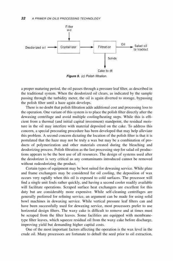
a proper maturing period, the oil passes through a pressure leaf filter, as described in
the traditional system. When the deodorized oil clears, as indicated by the sample
passing through the turbidity meter, the oil is again diverted to storage, bypassing
the polish filter until a haze again develops.
There is no doubt that polish filtration adds additional cost and processing loss to
the operation. One variant of this system is to place the polish filter directly after the
dewaxing centrifuge and avoid multiple cooling/heating steps. While this is effi-
cient from a thermal (and initial capital investment) standpoint, the residual mois-
ture in the oil may interfere with material deposited on the cake. To address this
concern, a special precoating procedure has been developed that may help alleviate
this problem. A second concern dictating the location of the polish filter is that it is
postulated that the haze may not be truly a wax but may be a combination of pro-
ducts of polymerization and other materials created during the bleaching and
deodorizing process. Polish filtration as the last processing step for salad oil produc-
tions appears to be the best use of all resources. The design of systems used after
the deodorizer is very critical as any contaminants introduced cannot be removed
without redeodorizing the product.
Certain types of equipment may be best suited for dewaxing service. While plate
and frame exchangers may be considered for oil cooling, the deposition of wax
occurs very rapidly when this oil is exposed to cold surfaces. The processor will
find a single unit fouls rather quickly, and having a second cooler readily available
will facilitate operations. Scraped surface heat exchangers are excellent for this
duty but are considerably more expensive. While self-cleaning centrifuges are
generally preferred for refining service, an argument can be made for using solid
bowl machines in dewaxing service. While vertical pressure leaf filters can and
have been successfully used for dewaxing service, most processors prefer to use
horizontal design filters. The waxy cake is difficult to remove and at times must
be scraped from the filter leaves. Some facilities are equipped with membrane-
type filter leaves, which squeeze residual oil from the waxy cake before discharge,
improving yield but demanding higher capital costs.
One of the most important factors affecting the operation is the wax level in the
crude oil. Many processors are fortunate to dehull the seed prior to oil extraction,
Figure 9. (c) Polish filtration.
32 A PRIMER ON OILS PROCESSING TECHNOLOGY
and as over 90% of the wax occurs on the seed (17), the problem is reduced at the
source. For those extracting the nondehulled seed, it is not uncommon to experience
wax levels in excess of 3000 ppm in the solvent-extracted crude oil. Unfortunately,
the trend is toward increased wax levels, as the hulls from high-oil-yield identity
preserved hybrid seeds have significantly higher wax content than less developed
seed species. Process control is very important to a successful dewaxing operation,
especially those installations using centrifuge separation. In order to provide effec-
tive crystal growth, phosphatides must be fully removed from the oil before enter-
ing the crystallizer vessels. Phosphorus interferes with crystal growth (in fact a
variant of lecithin is sold to inhibit haze formation), and additional pressure is
placed on the degumming operation to remove both hydratable and nonhydratable
phosphatides. Soap and moisture levels must be carefully controlled, as must
temperatures, retention times, and flow rates.
10. HYDROGENATION
While the processes discussed so far are mainly concerned with filtration, purifica-
tion, and removal of soluble and insoluble impurities in the oil, hydrogenation
involves an actual transformation of characteristics and properties of the oil through
chemical reaction in the presence of a catalyst. Hydrogenation allows the processor
to tailor the fat system for very specific applications and functions and is one of the
key functions of a value-added operation. Hydrogenation was developed to allow
vegetable oils as margarine and vanaspati products to substitute for butters and
ghees, and this market provides a huge outlet for much of the edible oils produced
today. Hydrogenation is generally performed for one of two specific purposes. The
first is to provide taste and smell stability and to enhance the shelf life for unsatu-
rated products. The second is to change the functional characteristics of the natu-
rally occurring fats to those required for a specific application. Hydrogenation
allows the baker and others to utilize margarines and shortenings while retaining
the functionality of products prepared with traditional lards and butters.
Simply stated, hydrogenation is designed to saturate (to the degree desired) dou-
ble bonds in the fatty ester of the triglyceride molecule. Hydrogenation (and to a
certain extent conditions found in deodorizing) also promotes isomerization of the
cis orientation to the trans position. While the fatty ester may contain from 12 to
22 carbon atoms and have a range of 0–3 double bonds, the most prevalent fatty
ester of seed oils has a chain length of 18 and has a maximum of 3 double bonds
in any given chain. The common names of these esters, based on the number of
double bonds, are linolenic (3 double bonds), linoleic (2 double bonds), oleic
(1 double bond), and stearic (fully saturated). The number of double bonds greatly
affects the fat properties, as does the orientation of the isomer. For example, the
melting point of a linolenic ester will be �13�C while the stearic ester will melt at
70�C. A cis isomer oleic may have a 16�C mp while the trans isomer oleic may
have a 44�C melting point (18). Clearly, these wide swings in properties are of great
interest to the modern food processor.
HYDROGENATION 33
Figure 10 depicts a typical hydrogenation system in use today. This flow-sheet
shows a dead-end reactor, as it is known, which traditionally has been an industry
standard. In operation, bleached oil is pumped from a holding tank with known
characteristics, including phosphorus, soap, and initial iodine value (IV), to the pre-
heating equipment. As the oil must be hot (typically 140�C or higher) before a reac-
tion commences, heating may be performed either externally or internally. In the
system illustrated, the feed oil is preheated with reacted hot oil to be filtered and
then is introduced into the reactor or a fill tank for final steam heating. During final
heating, the head space of the reactor is evacuated, removing not only any moisture
present in the system but also eliminating any gasses that may interfere with the
reaction. After the oil has been evacuated, and is at initial reaction temperature, cat-
alyst slurry is introduced into the reactor. Based on the desired properties of the
batch, the operator normally consults a ‘‘recipe book’’ to determine the reaction
temperatures and pressures, and calculates the required amount of catalyst and
hydrogen gas (usually estimated at 1 standard cubic meter per metric ton per IV
drop). The required values are normally entered into the corresponding measuring
and controlling equipment. After a brief period for agitation of the catalyst, hydro-
gen is introduced into the reactor.
During reaction, the automation equipment monitors the amount of gas delivered
and controls the pressure of reaction. Many U.S. processors control based on head-
space pressure, while many European facilities control based on hydrogen line pres-
sure. While pressures at these locations are usually not the same, especially during
the initial reactive period, consistency is the key, and the plant recipe book is written
according to the practices of the facility. Only the hydrogen that has been dissolved
in the oil is available for reaction, which is an extremely important consideration
in both the reactor and agitator design. As the reaction is exothermic, steam is
normally turned off when the gas is introduced, and after an allowable temperature
rise, cooling water is circulated through the reactor coils to maintain reaction
temperature. The reaction continues, with hydrogen gas delivered to maintain the
desired reaction pressure. Depending on the purity of the hydrogen gas, inert gases
accumulated in the reactor headspace may slow the reaction, and it is common
practice to vent a small amount of these (under 1%) to the atmosphere.
When most of the gas has been delivered, the operator may sample the oil and
measure the degree of saturation, typically using a refractive index. Upon verifica-
tion that the refractometer (correlating to the iodine value, a measure of degree of
unsaturation) shows the reaction is completed, the operator may vent the headspace
gas to the atmosphere or to another reactor and start evacuation of the vessel. It is
important that the headspace hydrogen gas be totally eliminated at this point, to
avoid the risk of a fire or other serious situation. An alternate to this venting pro-
cedure involves maintaining a positive pressure on the reactor at all times to avoid
the possibility of oxygen being introduced into the reactor. After securing the
reactor, the oil may be cooled and held for filtering, or may be discharged into a
drop tank where the feedstock for the next batch is preheated, as described earlier.
After this partial cooling, the oil typically passes through an oil–oil economizer to
bring the hard oil to filtration temperature, prior to entering the catalyst filter, or
34 A PRIMER ON OILS PROCESSING TECHNOLOGY
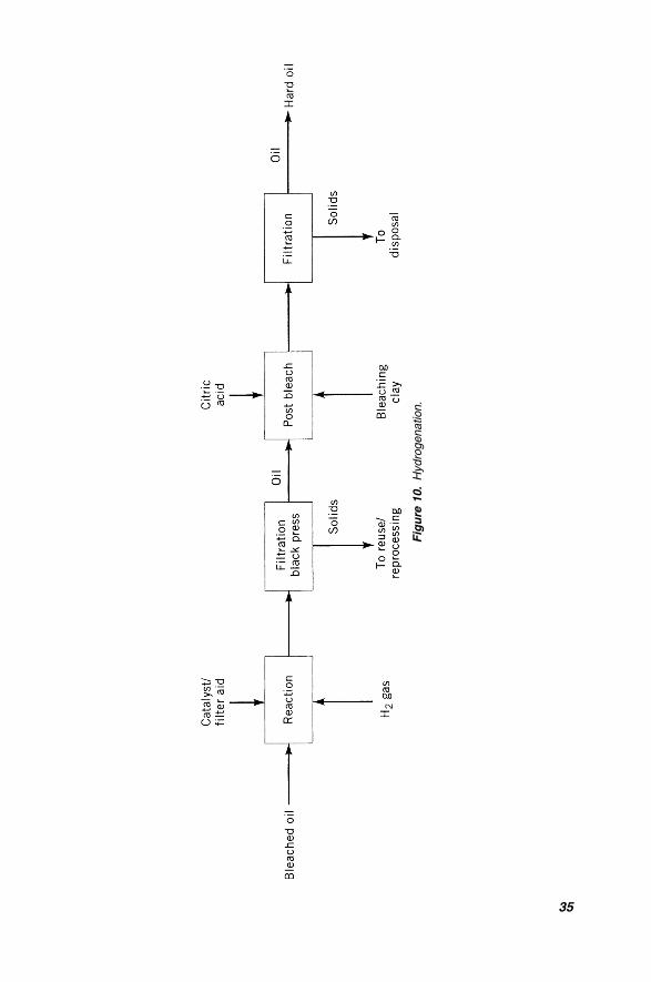
Fig
ure
10.
Hydro
genation.
35
black press. As the oil is highly reactive at this point and temperature control is very
important, special care is taken not to expose the oil to oxygen. After the catalyst
filter, the oil typically has a residual nickel content, which if used directly may
impart a gray-green appearance to the otherwise white hard fat. To remove the
remaining colloidal nickel, the oil may be slurried with a mixture of filter aid and
bleaching clay, agitated in an evacuated postbleacher and then filtered through a
final polishing filter. The bleaching earth is also used to compensate for any color
degradation that sometimes takes place after hydrogenation in a carbon steel reactor
(5). Chelation of the catalyst, using citric acid in place of the bleaching clay, has
gained acceptance in recent years, especially considering the additional equipment
necessary for the traditional postbleaching system and disposal problems associated
with bleaching clays. Some processors feel postbleaching can be minimized if cata-
lyst is not being reused. Many processors do reuse catalyst, although prediction of
resulting physical and chemical parameters of the hydrogenated product can
become more difficult. Hydrogen gas can be provided from a variety of sources.
For small or infrequent use operations, the processor may purchase commercial
hydrogen gas, stored on site using cryogenic storage or tube trailers. Larger opera-
tions may elect to generate their own hydrogen from steam reforming natural gas,
propane, or similar fuels. Hydrogen can also be generated from electrolytic crack-
ing operations and is generally viable in remote locations without commercial
hydrogen service.
Several options exist in hydrogenation system design. As mentioned earlier, the
dead-end reactor recirculates the hydrogen gas accumulated in the head-space above
the oil by a gas entrainment vortex blade of the turbine agitator. For large opera-
tions, a heat recovery system is often incorporated to utilize the exothermic heat of
reaction, using this heat for washwater/heating, heat tracing, or other imaginative
purposes. The gas recirculation-type converter, used extensively at one time,
operates by circulating large volumes of gas through the oil by means of external
compressors. This arrangement was popular when hydrogen gas contained consi-
derable quantities of inert gases; a small amount of gas could be vented continu-
ously, and the circulated gas provided the agitation (19). Another design popular
in Europe is the Buss reactor, which has no mechanical agitator, but provides
agitation by pumping oil through a headspace eductor. These systems provide
fast reaction times and boast high mass transfer rates, but do not provide the flexi-
bility of the dead-end reactor. Another concept is the helical impeller autoclave,
which is similar to the dead-end reactor but uses a specially designed agitation and
gas entrainment system. Continuous hydrogenation systems continue to be topics of
discussion for plants processing significant quantities of homogeneous product, and
it is expected that installations of this type will become more common.
As indicated earlier, the operator has several variables under his control to selec-
tively tailor the products. There are two types of selectivity the processor is most
concerned with, these being preferential and orientation selectivity. Preferential
selectivity refers to the double-bond position the hydrogen atom attaches itself to
during the saturation process. The study of orientation selectivity is centered on the
fact that during contact with the catalyst, some of the double bonds may be twisted
36 A PRIMER ON OILS PROCESSING TECHNOLOGY
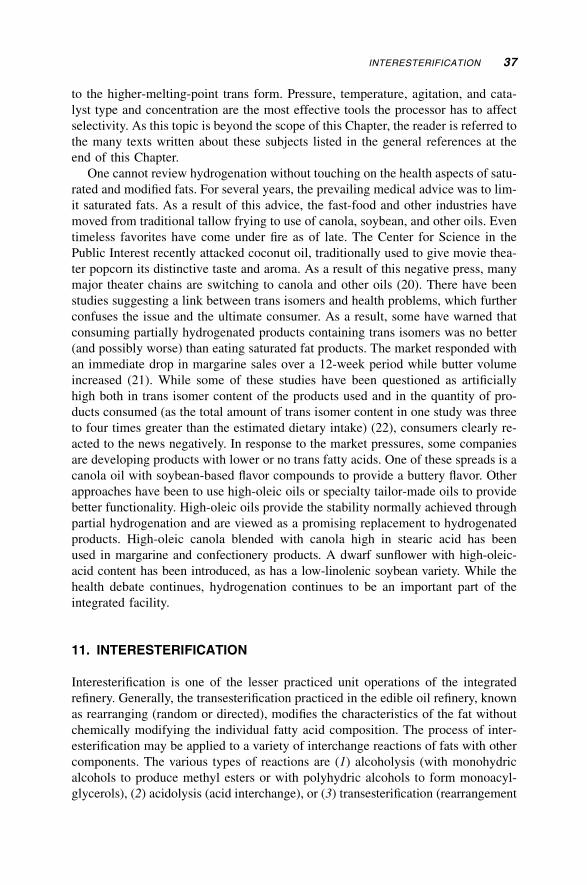
to the higher-melting-point trans form. Pressure, temperature, agitation, and cata-
lyst type and concentration are the most effective tools the processor has to affect
selectivity. As this topic is beyond the scope of this Chapter, the reader is referred to
the many texts written about these subjects listed in the general references at the
end of this Chapter.
One cannot review hydrogenation without touching on the health aspects of satu-
rated and modified fats. For several years, the prevailing medical advice was to lim-
it saturated fats. As a result of this advice, the fast-food and other industries have
moved from traditional tallow frying to use of canola, soybean, and other oils. Even
timeless favorites have come under fire as of late. The Center for Science in the
Public Interest recently attacked coconut oil, traditionally used to give movie thea-
ter popcorn its distinctive taste and aroma. As a result of this negative press, many
major theater chains are switching to canola and other oils (20). There have been
studies suggesting a link between trans isomers and health problems, which further
confuses the issue and the ultimate consumer. As a result, some have warned that
consuming partially hydrogenated products containing trans isomers was no better
(and possibly worse) than eating saturated fat products. The market responded with
an immediate drop in margarine sales over a 12-week period while butter volume
increased (21). While some of these studies have been questioned as artificially
high both in trans isomer content of the products used and in the quantity of pro-
ducts consumed (as the total amount of trans isomer content in one study was three
to four times greater than the estimated dietary intake) (22), consumers clearly re-
acted to the news negatively. In response to the market pressures, some companies
are developing products with lower or no trans fatty acids. One of these spreads is a
canola oil with soybean-based flavor compounds to provide a buttery flavor. Other
approaches have been to use high-oleic oils or specialty tailor-made oils to provide
better functionality. High-oleic oils provide the stability normally achieved through
partial hydrogenation and are viewed as a promising replacement to hydrogenated
products. High-oleic canola blended with canola high in stearic acid has been
used in margarine and confectionery products. A dwarf sunflower with high-oleic-
acid content has been introduced, as has a low-linolenic soybean variety. While the
health debate continues, hydrogenation continues to be an important part of the
integrated facility.
11. INTERESTERIFICATION
Interesterification is one of the lesser practiced unit operations of the integrated
refinery. Generally, the transesterification practiced in the edible oil refinery, known
as rearranging (random or directed), modifies the characteristics of the fat without
chemically modifying the individual fatty acid composition. The process of inter-
esterification may be applied to a variety of interchange reactions of fats with other
components. The various types of reactions are (1) alcoholysis (with monohydric
alcohols to produce methyl esters or with polyhydric alcohols to form monoacyl-
glycerols), (2) acidolysis (acid interchange), or (3) transesterification (rearrangement
INTERESTERIFICATION 37
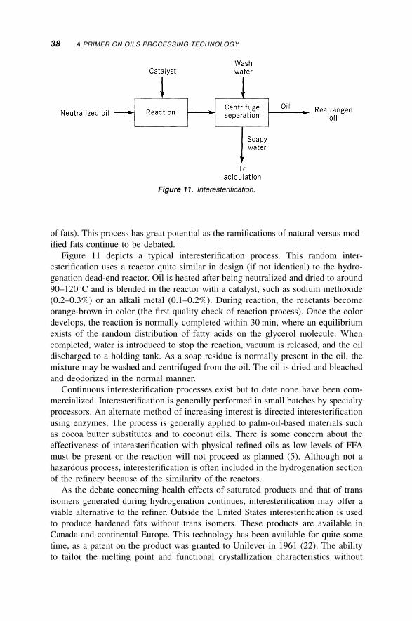
of fats). This process has great potential as the ramifications of natural versus mod-
ified fats continue to be debated.
Figure 11 depicts a typical interesterification process. This random inter-
esterification uses a reactor quite similar in design (if not identical) to the hydro-
genation dead-end reactor. Oil is heated after being neutralized and dried to around
90–120�C and is blended in the reactor with a catalyst, such as sodium methoxide
(0.2–0.3%) or an alkali metal (0.1–0.2%). During reaction, the reactants become
orange-brown in color (the first quality check of reaction process). Once the color
develops, the reaction is normally completed within 30 min, where an equilibrium
exists of the random distribution of fatty acids on the glycerol molecule. When
completed, water is introduced to stop the reaction, vacuum is released, and the oil
discharged to a holding tank. As a soap residue is normally present in the oil, the
mixture may be washed and centrifuged from the oil. The oil is dried and bleached
and deodorized in the normal manner.
Continuous interesterification processes exist but to date none have been com-
mercialized. Interesterification is generally performed in small batches by specialty
processors. An alternate method of increasing interest is directed interesterification
using enzymes. The process is generally applied to palm-oil-based materials such
as cocoa butter substitutes and to coconut oils. There is some concern about the
effectiveness of interesterification with physical refined oils as low levels of FFA
must be present or the reaction will not proceed as planned (5). Although not a
hazardous process, interesterification is often included in the hydrogenation section
of the refinery because of the similarity of the reactors.
As the debate concerning health effects of saturated products and that of trans
isomers generated during hydrogenation continues, interesterification may offer a
viable alternative to the refiner. Outside the United States interesterification is used
to produce hardened fats without trans isomers. These products are available in
Canada and continental Europe. This technology has been available for quite some
time, as a patent on the product was granted to Unilever in 1961 (22). The ability
to tailor the melting point and functional crystallization characteristics without
Figure 11. Interesterification.
38 A PRIMER ON OILS PROCESSING TECHNOLOGY
changing the fatty acid composition makes interesterification a process with inter-
esting potential. A comprehensive review on hydrogenation can be found in Ref. 23.
12. FRACTIONATION
Fractionation, or winterizing as it is sometimes called, is a practice gaining impor-
tance today. The phenomenon of winterizing was originally observed when storage
of refined cottonseed oil during cold weather caused deposition of high-melting-
point triglycerides leaving clear liquid oil on the top. The later was decanted, deo-
dorized, bottled, and marketed as a ‘‘winter salad oil’’ (24). While the commercia-
lized dry fractionation plant design is only some 30 years old, it is estimated that
around 10% of the world’s production passes through a fractionation plant (25).
Today, edible triglycerides are fractionated for one of the following reasons: (1)
to remove waxes and other nontriglycerides (2) to remove naturally occurring high-
melting-point triglycerides, or (3) to remove high-melting-point matcrials formed
during hydrogenation (26). Fractionation usually refers to the dry process, although
a wet or solvent process is also utilized. The wet fractionation process, which is
usually applied to cottonseed products, uses hexane or acetone, and allows separa-
tion of the various components in the miscella stage. However, the costs incurred
by solvent recovery, the hazardous nature of the operation, and the process losses
make the wet process less frequently used than dry fractionation.
Fractionation is widely practiced with palm oil, especially with the large amount
of palm olein exported from Southeast Asia, but is also used with tallow, lard, and
other fats. Fractionation of partially hydrogenated soybean oil (PHSBO), canola,
and other brush hydrogenated products is gaining importance as well. A typical
fractionation basestock may be a PHSBO with a feed IV of 100, fractionated into
a high stability liquid frying oil with the stearine used for margarine basestock.
Refined, bleached, and deodorized palm (RBD) with a starting 50–55 IV is
commonly fractionated into an 56 IV olein and 48 IV stearine.
A typical dry fractionation process is shown in Figure 12. The process involves
chilling the fat at a prescribed rate allowing the stearine to crystallize and then
Figure 12. Fractionation.
FRACTIONATION 39
separating the two phases by filtration. One of the key factors determining the suc-
cess of the fractionation process is the efficiency of the separation. Consequently,
both the crystallizing and subsequent filtration require careful control. The crystal-
lization cycle usually starts with the operator selecting one of several recipes pro-
grammed into the plant PLC, depending on the feedstock and desired products. The
process then continues by loading a cell (or crystallizer) with a prescribed quantity
of dry (and for seed oils, hydrogenated) feedstock. The oil is normally loaded suffi-
ciently hot to melt any components that could interfere with the crystal deve-
lopment process, and to melt any crystallized fat present in the system from a
previous batch. After a brief holding period, the system controller then starts the
flow of chilled propylene glycol (or water) through the crystallizing cooling coils
and jacket. In some designs, a direct expansion refrigeration system is provided,
eliminating the glycol system so that the crystals form and grow properly; the tem-
perature differential between the oil and coolant is carefully controlled during this
initial cooling period. During this cycle, agitation is introduced by either very slow
rotation of mechanical agitators or by bubbling cold air through the cell. After a
certain period, the temperature differential is changed for the crystal maturing
phase, and the agitation may be reduced or stopped.
For certain products, stearine seeds may be introduced during the cycle to pro-
vide a stable base for crystal growth. Agitation during the crystallizing process is
necessary but also potentially detrimental to the process. Without sufficient agita-
tion, the heat transfer rate becomes very low and the coil surfaces build up with
crystallized fat. Too much agitation breaks up the crystals and imparts mechanical
work into the mixture. A balanced agitation has been shown to be necessary for
proper crystal formation, as an olein–stearine mixture slowly cooled without agita-
tion produces a stiff and nonpourable mass. Photomicrographs showed that large-
sized crystals were formed having long thin tentacles that trapped liquid oil within
the crystal structure (26).
After the proper crystallizing period, the stearine fraction is separated from the
olein by one of several filtration methods. From the crystallizer cells, the oil mix-
ture is either gently pumped or is transferred by gravity or slight pressurization of
the cells to the filter. The olein fraction passes through the filter media while the
solid stearine fraction is trapped. The stearine is then dropped into a receiver where
it is melted and pumped to a holding tank. The olein may be blended with a crystal
inhibitor, such as phosphatides, polyglycerol esters of mixed fatty acids, or other
commercial inhibitors, to increase the time of the cold test. The cold test involves
chilling and holding oil at or near freezing temperature for a certain period of time.
Fractionation is designed to separate the various fractions based on differences
in crystallizing temperatures. Often, the products of a single fractionation are not
sufficiently fine tuned to produce some of the higher value specialty fats. Hence, the
concept of double fractionation was introduced, with one of the phases (usually the
olein) refractionated. This process is used quite frequently with palm oil. The pro-
ducts of the second fractionation are a ‘‘super’’ olein and a stearine used as tropical
margarine base or a confectionery base.
40 A PRIMER ON OILS PROCESSING TECHNOLOGY
While the designs of commercially available crystallizer cells have some vari-
ances, all are intended to cool and agitate the oil as a batch more or less in the
same manner. There are, however, several types of filters in use based on the pro-
ducts and style of operation. These basic designs include plate and frame filters,
continuous vacuum systems, membrane systems, and pressure leaf designs.
At one time, plate and frame filters were standard equipment for fractionation
service, especially for cottonseed applications. It is generally necessary to introduce
the oil–stearine mixture into the filter by gravity during the first hour of operation
and then apply low air pressure to the tank forcing the mixture through the filter. As
these designs require location within a refrigerated room, are generally high in
labor requirements, and have slow filtration rates, they have largely been replaced
by other designs. A modern variant of the traditional plate and frame design that is
gaining acceptance is a filter press equipped with membrane plates. When the crys-
tals are rather small and hard, a membrane system provides an excellent olein–
stearine yield. The membrane filter is similar to a traditional plate and frame press,
except that each chamber is equipped with one or more flexible membranes, such as
rubber or polypropylene. The operation of this system involves a filtration step
where olein passes through with the stearine retained in the chamber. Next, a squeez-
ing takes place where compressed air is applied behind the membranes to expel the
trapped olein, leaving the hard stearine cake. Finally, the chambers are opened
and the cake discharged into the melting tank. Yields from membrane filters are
usually quite high, and the entire process has been automated to reduce the labor
requirements. However, membrane filters tend to be rather capital intensive and
require replacement of the limited life membranes.
A very popular filtration system is the continuous vacuum filter. When the stear-
ine crystals are durable and less sensitive to deformation during filtering (such as
cake from PHSBO or palm), this filter provides an excellent separation. The intro-
duction of this technology represented a major advance as filtration rates were
increased several magnitudes over the rates observed with plate and frame systems.
Operation of the vacuum filter is well suited for large-capacity operations as oil
from the crystallizer cell is gently and continuously pumped to the filter receiver.
A slowly rotating drum, partially submerged in the oil, uses vacuum to draw the oil
through the filter of the compartmentalized drum. The air–olein mixture is sepa-
rated and the filtrate discharged to a holding tank. The stearine cake collects on
the rotating drum and is dried as the drum turns. As the drum rotates to the dis-
charge section, the cake is removed from the filter cloth by either a knife blade,
string discharge, or a blast of air, and drops into the stearine receiver for melting
and subsequent pumping to storage. The vacuum filter is often hood shrouded for
hygienic and temperature control purposes.
A popular variant of the rotating drum vacuum filter has been widely applied
especially for the palm oil industry. The Florentine vacuum filter uses a horizontal
stainless steel perforated belt with vacuum applied under the belt. This design
includes a recycle from the first filter section, which is said to allow the first layer
of stearine to act as a continuous precoat (25).
FRACTIONATION 41
Another type of filter in use today is a horizontal (or vertical) pressure leaf filter
with a special cake squeezing device. Between each pair of hollow filter leaves is an
impermeable flexible diaphragm that can, when inflated, apply pressure on one side
of each adjacent leaf. As the cake forms, the pressure on the leaf side is less than on
the chamber side. The diaphragms move toward the leaf, compressing the olein
from the stearine cake.
Dry fractionation applications have enjoyed substantial growth in the past
years, and with growing emphasis on value-added specialty fats, the processor
finds fractionation a most valuable tool. It is expected that rapid growth fractio-
nation capacity will occur as processors search for additional revenue enhance-
ment opportunities.
13. DEODORIZATION AND PHYSICAL REFINING
Typically the last step in the edible oil refinery is deodorization, and this process
is included in almost every refining operation, regardless of the other unit opera-
tions selected. While in the past limited natural fats could be utilized as edible pro-
ducts (such as butter and animal fats), most oils used today come from sources
having natural components that if not removed impart objectionable flavors and
tastes. These oils contain not only flavor bodies that must be eliminated to produce
a palatable product but other unit operations, such as hydrogenation, impart a nega-
tive flavor and color that must be removed in the deodorizer. Shelf life and color are
also important considerations upon which the deodorizer has a direct impact.
Deodorizing was developed to remove the relativity volatile odoriferous com-
pounds from the host triglyceride. From the early efforts to boil the volatiles at
atmospheric conditions and high temperatures, the modern practice of applying
heat under low absolute pressure for a particular period of time has developed.
As there is a substantial difference between the vapor pressure of the oil and the
volatile materials affecting the flavor, color, and stability, deodorizing can consist
of any method to evaporate these substances without damaging the oil.
Physical refining refers to the process where the free fatty acids in a crude or
degummed oil are removed by evaporation rather than being neutralized and
removed as soap in an alkaline refining process. In design and operation, the deo-
dorizer is very much like the physical refiner, with the major exception being the
higher load of fatty acid removed in physical refining. While some deodorizing
designs can use carbon steel for certain noncontacted parts (such as the outer shell
for a double-shell deodorizer), the high level of fatty acids (and subsequent corro-
sion if left unchecked) generally demands that a physical refining system be made
from stainless steel or other material not affected by contact with fatty acids. A
physical refining operation should also have sufficient heating capacity to compen-
sate for the cooling produced during fatty acid evaporation, which is normally a
negligible figure for alkali-neutralized feedstocks.
Deodorization is a mass transfer purification process, where the oil is exposed to
surface conditions forcing the volatiles into the vapor state. Deodorizing conditions
42 A PRIMER ON OILS PROCESSING TECHNOLOGY
normally involve exposing a thin film of oil to a carrier gas at an elevated tempe-
rature and low pressure. A stripping gas (normally steam) is usually introduced
to agitate the oil, ensuring that all the oil is subjected to surface conditions, and to
carry the volatiles from the deodorizer to the vapor recovery system. One of the key
factors in successful deodorization is to provide thin-film mass transfer for each
particle of oil. Each of the deodorizing concepts described attempts to provide some
type of rapid agitation to accomplish this duty. Heat bleaching is also normally pro-
vided in most deodorizing designs, which refers to the process occurring at these
conditions where the carotenoid pigments and other colorizing compounds either
break down or are evaporated. Effective deodorization requires this exposure and
agitation to be performed for a certain period of time, not only to ensure equili-
brium conditions but also to provide sufficient time for heat bleaching.
Figure 13a depicts the unit functions in a typical deodorizing system in use
today. From the bleaching plant (or physical refining pretreatment process) the oil
(normally at 60–90�C) is first deaerated. This step is extremely vital prior to heating
the oil to temperatures over 100�C, as most oils, especially those derived from seed
sources, will deposit products of polymerization when oil containing oxygen is
exposed to heating surfaces. The deaerator may be a separate vessel or in the
case of certain designs, an integral part of the deodorizer itself. After the deaerator,
the oil normally passes through an oil–oil interchanger, being preheated by freshly
deodorized product. The hot oil is then heated to deodorizing temperature. These
heat exchangers can either be external to the deodorizer or these heating (and cool-
ing) functions can be performed under the same vacuum conditions as the deodorizer
itself. After being brought to temperature, the oil is vigorously agitated in the deo-
dorizing vessel for a certain period of time until the bulk of the volatiles are
removed and heat bleaching is accomplished. The oil is then cooled, normally first
passing through a heat recovery economizer as described above, and then through
final cooling. During cooling, a small amount of chelating agent, such as citric acid,
may be introduced into the oil, as may an antioxidant. The volatiles removed during
the deodorizing process are condensed and usually recovered in a fatty material
direct condenser, known as a vapor scrubber. The balance of the volatile gases,
including the stripping steam and other more volatile compounds, are condensed in
the vacuum system.
While the basic principles behind any deodorizer are essentially the same, there
are several types of systems used to perform these functions. General classifications
include the batch, continuous, and semicontinuous operations.
The batch process, which was the first type of deodorizer to be developed, gene-
rally uses a single vessel to accomplish the functions desired. These units, which
are generally suitable for total daily output of under 60 metric tons per 24 h, consist
of relatively tall vertical cylindrical vessels designed for substantial level rise
during the steam agitation process. A batch of incoming fresh oil is normally slowly
heated under vacuum conditions to deodorizing temperature, at which time sparg-
ing steam is introduced through a sparging pipe, or through a gas-lift pump. After a
suitable agitation period (which is normally several hours) the oil is cooled, under
vacuum conditions, and is discharged to storage. While heating and cooling are
DEODORIZATION AND PHYSICAL REFINING 43
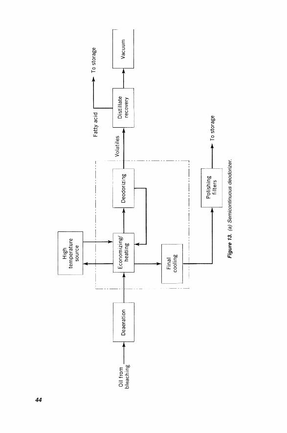
Fig
ure
13.
(a)
Sem
icontinuous
deodorizer.
44
normally performed in the vessel utilizing internal coils, forced circulation through
external heat exchangers allows for a quicker cycle and possibly lower overall
utility costs. Because of the relatively small batches involved, the long times
between filling and emptying, and the economies of scale, heat recovery is normally
not incorporated in batch deodorizing designs.
The continuous deodorizer, illustrated in Figure 13b, performs the same basic
functions but is designed for a larger operation requiring few changes of stocks
per day. The continuous deodorizer allows for low utility consumption, reduced
labor costs, and high heat recovery and is generally the best choice for the modern
integrated refiner who is sufficiently flexible in scheduling production runs. There
are several options for continuous deodorizer design today, but the following
description follows a typical installation found in a modern integrated facility.
The bleached oil enters the deaerator where, operating at 50 mm Hg absolute or
less, oxygen and some moisture are removed prior to heating to deodorizing tem-
perature. The deaerator is normally fitted with a demister to eliminate oil carryover
to the vacuum system. After the deaerator, the oil passes through the economizer
and then the final oil heater. The final oil heater is normally designed to heat the
incoming oil to final temperature using high-pressure steam or thermal fluid. The
oil then enters the deodorizer, which is normally a single-shell vertical unit (or a
horizontal vessel) designed for operation of 3 torr (or less) at the vapor outlet.
The vessel has several deodorizing compartments fitted with special steam distribu-
tion devices to promote intimate contact between the oil and steam. These devices
can be gas-lift pumps (also called mammoth pumps) or sparge rings. The retention
time in each compartment varies between 10 and 30 min, depending on the design.
As the oil passes through a series of baffles installed in the trays, it overflows
through a overflow pipe or weir to the next lower tray. After a sufficient deodorizing
period, the oil is ready for cooling. In order to achieve the high heat recovery typi-
cal for continuous deodorizers the oil is often brought outside the vessel and is
cooled in an oil-to-oil economizer, as described above. To provide additional cool-
ing or to compensate for a lack of cooling media when changing feedstock, an inter-
mediate cooler is also often provided. After cooling, a small amount of citric acid
(around 200 ppm) is introduced to chelate any trace metals present in the oil. Cer-
tain oils, such as palm and lauric oils, can safely be delivered to storage at this
point, while other oils, such as soybean, may develop flavor and stability problems
if cooled to storage temperatures under pressure conditions. It is theorized that the
development of substances detrimental to flavor occur very rapidly at temperatures
present in the deodorizer, and without constant removal of these volatile compo-
nents, the oil quality is affected. If cooling is accomplished entirely under vacuum,
these volatiles are removed almost as fast as they are formed. To remove these vola-
tiles formed under pressure conditions while the oil is being cooled, the oil is often
reexposed to low-pressure conditions in a flash vessel or a lower section of the deo-
dorizer after external heat exchange. Finally, the oil is passed through a tubular or
polyester bag filtration system to remove any particulate material that may have
been picked up in previous operations.
DEODORIZATION AND PHYSICAL REFINING 45
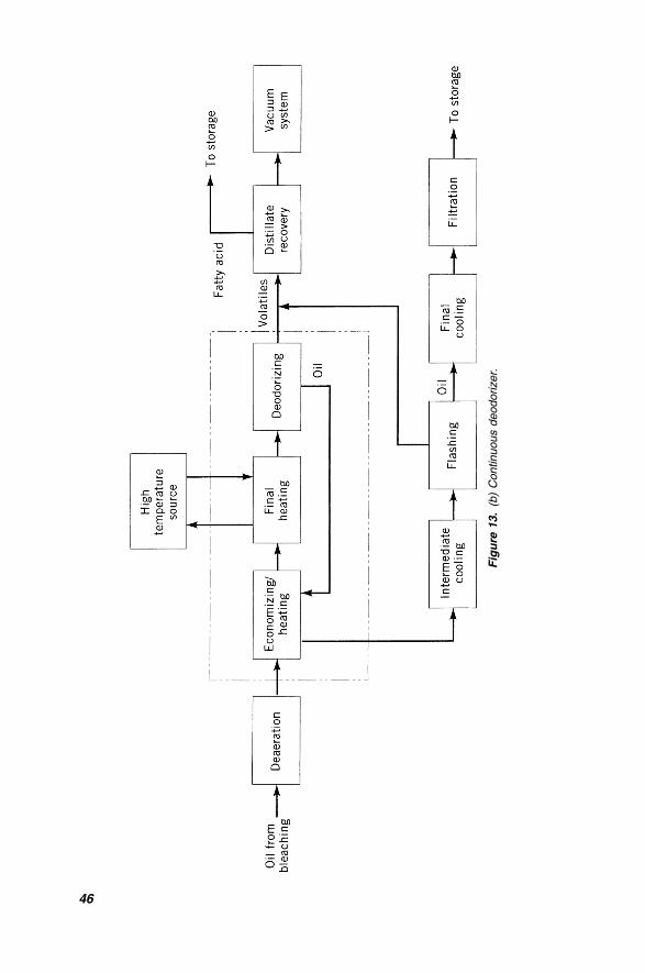
Fig
ure
13.
(b)
Continuous
deodorizer.
46
Continuous deodorizers can be supplied with many options tailored to the speci-
fic application. For example, while maximum heat recovery is usually accomplished
using external heat exchangers, the continuous vessel can be designed to perform
all heating and cooling functions internally. Orientation of the piping, vessels, and
heat exchangers can be arranged to minimize product contamination during stock
change. A variety of heat recovery options have been developed, including a design
generating steam to assist driving the vacuum system.
As mentioned earlier, there are several configurations of continuous deodorizers
in addition to the traditional vertical tray unit described above. One type uses a
multisectioned tray (box) contained in a horizontal cylindrical vessel. Heat transfer
baffles are used as flow baffles, with agitating steam injected between the baffles.
Another system is based on a series of vertically stacked horizontal single-shell
cylindrical vessels, with agitation steam injected by multiple pipe distributors
running the length of the vessel. Another type of continuous deodorizer takes maxi-
mum use of thin-film processing, using structured packing to maximize the steam–
oil contact. This system provides excellent fatty acid stripping with a minimum of
steam, but because of the relatively short retention times involved, it does not
provide a great deal of heat bleaching unless a retention vessel is provided as part
of the system.
The semicontinuous deodorizer, Figure 13a, again follows much of the same
processes but is specifically designed for an operation demanding frequent stock
changes. Like the continuous deodorizer, many variants are in operation today,
some utilizing multiple deodorizing sections, a greater number of heat recovery
options, etc. The process described is for a typical unit found in operation today.
Semicontinuous deodorizers, developed in the late 1940s, were specifically designed
to process an individual batch of oil in a fixed-capacity tray, allowing the operator to
follow one batch of oil with a different feedstock with minimum lost production
time and contamination. The term semicontinuous stems from the fact that although
each batch is treated individually (with heating, deodorizing, and cooling functions
performed in a specific tray of the vessel), the flow to and away from the deodoriz-
ing vessel is generally continuous. As significant temperature swings occur during
the cycle, and heat exchange ability is limited by physical constraints of the avail-
able surface area and operating conditions, overall heat recovery in the semiconti-
nuous deodorizer is typically around 50–60%. The semicontinuous design requires
considerable control to manage the drop valves and stock change system, and its
installed cost is typically greater than a similarly sized continuous design.
In operation, properly pretreated oil flows continuously to the measuring tank.
This tank, which usually also performs the deaeration function, accumulates oil
at a constant rate. When signaled by the plant control system, a drop valve opens
for 1–2 min to admit a quantity of oil into the top heating tray before closing. In this
first of a typical five-tray configuration, the oil is preheated using a device com-
monly known as a thermosyphon. This process uses the temperature differential
between the cold incoming feedstock and the high temperature of deodorized oil
in a lower holding section using steam or thermal fluid as the heat transfer medium.
This medium is naturally circulated by alternately evaporating in the holding
DEODORIZATION AND PHYSICAL REFINING 47
section while condensing in this preheating section or is pumped for a single-phase
fluid. After the proper period, the preheat tray drop valve opens briefly to discharge
the oil to the final heating tray. This tray, which is also packed tightly with coils,
uses high-pressure steam or thermal fluid to bring the oil to proper deodorizing
temperature. After a suitable period, the drop valve on this tray opens, and the
oil drains into the deodorizing tray. Now at deodorizing temperature, the oil is sub-
jected to high agitation through either a single or series of mammoth pumps, as
described in the continuous deodorizing section. When the deodorizing period
is over, the drop valve opens, and the oil flows to the holding tray. This tray, which
forms the lower section of the thermosyphon heat transfer system described above,
allows the oil to partially cool and is a main source of heat recovery in the semi-
continuous system. After a suitable period, the oil is discharged to the final cooling
tray, where cooling water (or other cooling fluid) brings the oil to (or close to) final
storage temperature. Finally, the oil enters the holding section, where it is pumped
continuously by the discharge pump through final polish filtration on its way to
storage. An external cooler may also be supplied to reduce the oil temperature prior
to storage.
Traditionally, the deodorizer was considered the last step in the refining process.
For a custom blend shipment, basestocks were blended and after being deodorized
were loaded directly on a customer’s vessel. Even with a homogeneous oil product,
deodorizing was performed almost immediately prior to loadout to provide the
freshest oil possible. With an increased use of stainless steel piping and equipment,
and judicious use of inert gas purging, several commercial operations have found it
acceptable to hold deodorized product for a longer period of time, and in fact per-
form blending of deodorized products without redeodorizing the load. As customer
requirements are quite variable, especially for higher value custom fat blends, and
the concern of scheduling and potential contamination is significant, this practice
allows a longer run of product through a plant system, resulting in smoother opera-
tion without the need for frequent changeovers. This practice also eliminates much
of the previous justification for a stock change deodorizer.
While the deodorizer generally represents the final step in edible oil processing,
and can make a good product from less than perfect feedstock, the deodorizer
cannot forgive the sins made in earlier processes. While the primary products of
oxidation are removed (as indicated by the peroxide value), severely damaged oil
may contain secondary products of oxidation (measured as anisidine value). Phos-
phatides must be at very low levels prior to entering the deodorizing system. Soaps
must also be completely eliminated and the oil must be handled and stored to mini-
mize exposure to oxygen.
14. SHORTENING AND MARGARINE MANUFACTURING
Shortenings are edible fats that have undergone special processing to yield products
with certain physical characteristics. They are suitable in a wide variety of applica-
tions but are primarily used in cooking and baking of foods. Shortenings act to
48 A PRIMER ON OILS PROCESSING TECHNOLOGY
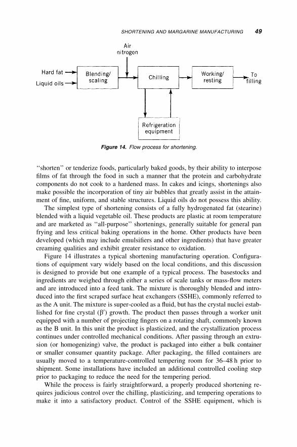
‘‘shorten’’ or tenderize foods, particularly baked goods, by their ability to interpose
films of fat through the food in such a manner that the protein and carbohydrate
components do not cook to a hardened mass. In cakes and icings, shortenings also
make possible the incorporation of tiny air bubbles that greatly assist in the attain-
ment of fine, uniform, and stable structures. Liquid oils do not possess this ability.
The simplest type of shortening consists of a fully hydrogenated fat (stearine)
blended with a liquid vegetable oil. These products are plastic at room temperature
and are marketed as ‘‘all-purpose’’ shortenings, generally suitable for general pan
frying and less critical baking operations in the home. Other products have been
developed (which may include emulsifiers and other ingredients) that have greater
creaming qualities and exhibit greater resistance to oxidation.
Figure 14 illustrates a typical shortening manufacturing operation. Configura-
tions of equipment vary widely based on the local conditions, and this discussion
is designed to provide but one example of a typical process. The basestocks and
ingredients are weighed through either a series of scale tanks or mass-flow meters
and are introduced into a feed tank. The mixture is thoroughly blended and intro-
duced into the first scraped surface heat exchangers (SSHE), commonly referred to
as the A unit. The mixture is super-cooled as a fluid, but has the crystal nuclei estab-
lished for fine crystal (b0) growth. The product then passes through a worker unit
equipped with a number of projecting fingers on a rotating shaft, commonly known
as the B unit. In this unit the product is plasticized, and the crystallization process
continues under controlled mechanical conditions. After passing through an extru-
sion (or homogenizing) valve, the product is packaged into either a bulk container
or smaller consumer quantity package. After packaging, the filled containers are
usually moved to a temperature-controlled tempering room for 36–48 h prior to
shipment. Some installations have included an additional controlled cooling step
prior to packaging to reduce the need for the tempering period.
While the process is fairly straightforward, a properly produced shortening re-
quires judicious control over the chilling, plasticizing, and tempering operations to
make it into a satisfactory product. Control of the SSHE equipment, which is
Figure 14. Flow process for shortening.
SHORTENING AND MARGARINE MANUFACTURING 49
normally cooled by direct expansion of ammonia liquid, involves monitoring both the
product and refrigerant temperatures. Plastic fats at room temperatures may contain
between 10 and 30% solid crystal fraction dispersed in the liquid oil, depending on
the formulation and the oils used. The most important factors governing the product
are the number, size, and structure of the crystal solids dispersed in the liquid oil. A
slowly cooled fat crystallizes in relatively few and large granular clusters. Such a fat
exhibits less plasticity and is not as firm as is a rapidly chilled fat where many small
and well-dispersed crystal solids are developed. A fat with large crystals has a
‘‘gritty’’ feel in the mouth and can best be demonstrated by heating and subsequent
cooling of a commercial shortening product. While the properly prepared product
will appear homogeneous and have an agreeable mouthfeel, an uncontrolled heating
and subsequent cooling operation will produce a fat with large crystals, in which
the liquid and solid portions may separate. Because crystals of the solid fat fraction
are polymorphic (existing in more than one crystalline form), quick solidification
and subsequent plasticizing functions require careful control to ensure functional
products with stable crystalline structures. The conditions of supercooling can be
established to take advantage of crystal reorientation, or tempering, which is
allowed to take place during storage. Proper crystal reorientation will yield a higher
melting product and a more stable crystal pattern.
In addition to the operations discussed, it is also common practice to introduce
8–12% nitrogen or air into the chilled product. The effect of incorporating gas into
the shortening is to improve its textural appearance and color, stabilize it by making
it more homogenous, and improve its creaming properties by contributing gas to
expand dough and batter for subsequent baking operations.
While shortening is primarily a fat product, margarine is generally defined as a
plastic fat food product containing 80% (U.S. minimum) edible fat with the balance
of about 20% consisting of an aqueous phase (usually a specially cultured skim
milk) and including salt, vitamins, food coloring, and other additives. In addition,
a host of spreads containing greater aqueous and lessor oil phases have been deve-
loped and widely accepted by the consumer.
Unlike household shortening, consumer margarine is generally consumed as a
spread on bread as well as for home cooking and baking. Margarines must therefore
melt readily and completely in the mouth and impart ‘‘buttery’’ characteristics to
products containing them. Any residue that fails to melt at body temperature may
not be noticeable in a shortening (in fact, such a residue may be desirable to give
shortening high-temperature firmness), but in margarine it imparts an undesirable
‘‘pasty’’ sensation in the mouth. An ideal margarine should be plastic and spread
freely on soft, fresh bread. At refrigerator temperatures, however, it should be suffi-
ciently firm to permit forming into the desired package for marketing. Margarine
also differs from shortening insofar as flavor is concerned. Shortenings are invari-
ably produced to be completely bland whereas margarine is modeled after butter. It
is essential that the basestocks for margarine production are properly processed and
well deodorized.
A typical process flow for margarine production is shown in Figure 15. While
several types of margarine are produced today, and each has its own variant of the
50 A PRIMER ON OILS PROCESSING TECHNOLOGY
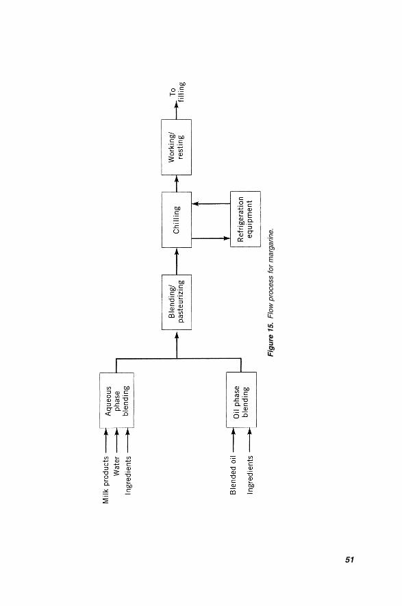
Fig
ure
15.
Flo
wpro
cess
for
marg
arine.
51
processing stages followed, the basic process is similar with most configurations.
The oil phase (and oil-soluble components) are weighed through a series of scale
tanks or in-line batch metering equipment. Meanwhile, potable water is blended
with milk products and other aqueous-phase ingredients, with inventory of all com-
ponents carefully measured and recorded. As the aqueous phase provides an excel-
lent growth media for harmful bacteria, it must be very carefully prepared and must
be sterilized. To ensure proper blending, aqueous-phase tanks are usually equipped
with hot-water jackets and high-efficiency turbine agitators. After thorough mixing,
the aqueous phase is carefully blended with the oil phase, and the mixture is heated
to pasteurizing temperature either in a batch pasteurization process or in an inline
sterilization process. The mixture is then cooled, often using a regenerative heat
exchanger and, when ready, is pumped to the scraped surface heat exchangers. Pres-
sures associated with margarine manufacturing can be quite high, with some puff
pastry products requiring upward of 50–55 bars pressure at the inlet of the SSHE.
As mentioned earlier, there are several variants of margarine in production today.
Table margarine, a traditional 80% fat product, typically passes through one set of
coolers, then through an intermediate worker/resting unit, and through a final SSHE
prior to packaging as wrapped bricks. Tub-filled margarine may follow a similar
path, except it may not pass through the intermediate worker unit, but rather passes
through a worker unit after the final SSHE, staying somewhat less plastic until after
filling. An example of cake margarine (or biscuit fat) production involves passing
the product through a SSHE, then an intermediate worker, then a second SSHE, and
finally through worker/resting units prior to packaging in cartons. Puff pastry mar-
garine may be subjected to as many as three cooling and subsequent intermediate
working steps prior to final cooling. After final cooling, puff pastry product may
pass through a ‘‘resting tube,’’ which provides a controlled amount of retention
time and mechanical working prior to packaging (27). Several other variants exist,
and it is common for individual facilities to develop their own hybrid process after
observing the impact of the various operations on the product (and often changing)
market. The modern production facility is suitably flexible to change the configura-
tion depending on local conditions. Like shortening manufacturing, control of the
SSHE equipment, which is normally cooled by direct expansion of ammonia gas,
involves monitoring both the product and refrigerant temperatures.
While the basic process of margarine manufacturing is fairly straightforward,
much of the secret for success lies with the formulations and processing conditions
established to develop the functionality demanded for the specific application. Since
plasticity and spreadability are two of the most important physical properties of
margarine, the ratio of crystal solids to oil over a given temperature range should
be used to determine the exact quantities of the various fats and oils to be blended
together. Milk, or milk, powder, may be favored for margarine productions as it
imparts the desired flavor and aroma to the product. Milk also aids in the production
and stabilization of the emulsion and provides certain nonfat ingredients that
give the characteristic aroma akin to butter. It is generally necessary to add special
emulsifying agents to margarine in order to achieve the physical properties associa-
ted with this product. Improperly emulsified or inadequately stabilized margarine
52 A PRIMER ON OILS PROCESSING TECHNOLOGY
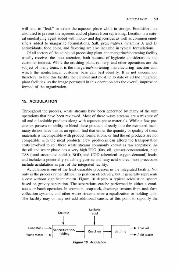
will tend to ‘‘leak’’ or exude the aqueous phase while in storage. Emulsifiers are
also used to prevent the aqueous and oil phases from separating. Lecithin is a natu-
ral emulsifying agent added with mono- and diglycerides as well as common emul-
sifiers added to margarine formulations. Salt, preservatives, vitamins A and D,
antioxidants, food color, and flavoring are also included in typical formulations.
Of all sectors of the edible oil processing plant, the margarine/shortening facility
usually receives the most attention, both because of hygienic considerations and
customer interest. While the crushing plant, refinery, and other operations are the
subject of many tours, it is the margarine/shortening manufacturing function with
which the nontechnical customer base can best identify. It is not uncommon,
therefore, to find this facility the cleanest and most up to date of all the integrated
plant facilities, as the image portrayed in this operation sets the overall impression
formed of the organization.
15. ACIDULATION
Throughout the process, waste streams have been generated by many of the unit
operations that have been reviewed. Most of these waste streams are a mixture of
oil and oil-soluble products along with aqueous-phase materials. While a few pro-
cessors possess to ability to blend these products directly into the extracted meal,
many do not have this as an option, find that either the quantity or quality of these
materials is incompatible with product formulations, or find the oil products are not
compatible with the meal products. Few producers can afford the transportation
costs involved to sell these waste streams commonly known as raw soapstock. As
the oil and water phase has a very high FOG (fats, oil, grease) concentration, high
TSS (total suspended solids), BOD, and COD (chemical oxygen demand) loads,
and includes a potentially valuable glycerine and fatty acid source, most processors
include acidulation as part of the integrated facility.
Acidulation is one of the least desirable processes in the integrated facility. Not
only is the process rather difficult to perform effectively, but it generally represents
a cost without significant return. Figure 16 depicts a typical acidulation system
based on gravity separation. The separations can be performed in either a conti-
nuous or batch operation. In operation, soapstock, discharge streams from tank farm
collection systems, and other waste streams enter a equalization or holding tank.
The facility may or may not add additional caustic at this point to saponify the
Figure 16. Acidulation.
ACIDULATION 53
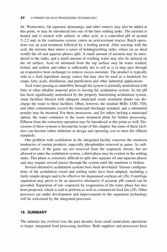
fat. Washwaters, fat separator skimmings, and other sources may also be added at
this point, or may be introduced into one of the later settling tanks. The mixture is
heated and is treated with sulfuric or other acid, at a controlled pH of around
2–2.2 and, in the continuous system, enters an acid-resistant reactor. Batch opera-
tions use an acid treatment followed by a boiling period. After reacting with the
acid, the mixture then enters a series of holding/settling tanks, where (in an ideal
world) the oil and aqueous phases split. A small amount of aeration may be intro-
duced in the tanks, and a small amount of washing water may also be sprayed on
the oil surface. Acid oil skimmed from the top surface may be water washed,
boiled, and settled, and either is sufficiently dry to sell as is or may pass through
an evaporative heat exchanger to remove excess moisture. The product is typically
sold as a feed ingredient energy source but may also be used as a feedstock for
soaps, fatty acids, distillation, and purification and other industrial applications.
Acid water passing as underflow through the system is normally neutralized with
lime or other alkaline material prior to leaving the acidulation system. As the pH
has been significantly neutralized by the properly functioning acidulation system,
some facilities blessed with adequate municipal waste treatment plants can dis-
charge the water to these facilities. Often, however, the residual BOD, COD, TSS,
and other contaminants exceed the municipal discharge standard, and a substantial
penalty may be incurred. For these processors, and for others lacking a municipal
option, the water continues to the waste treatment plant for further processing.
Effluent from the extraction operation may be introduced at this point as well. Dis-
cussion of these systems is beyond the scope of this chapter, but some of these facil-
ities can become rather elaborate in design and operating cost to meet the effluent
standards.
One problem with acidulation in the integrated facility concerns the emulsion
tendencies of certain products, especially phosphatides removed as gums. As indi-
cated earlier, if the gums are not removed from the soapstock stream, but are
allowed to enter the acidulation system, a third phase may be evident in the settling
tanks. This phase is extremely difficult to split into separate oil and aqueous phases
and may require several passes through the system until the emulsion is broken.
Several alternative acidulation systems have been developed. Various configura-
tions of the acidulation vessel and settling tanks have been adapted, including a
fairly simple design said to be effective for degummed soybean oil (28). Centrifuge
separation may prove to be an attractive alternative if accurate pH control can be
provided. Separation of raw soapstock by evaporation of the water phase has also
been proposed, which is said to perform as well as commercial feed fats (29). Other
processes are under development and improvements to the separation technology
will be welcomed by the integrated processor.
16. SUMMARY
The industry has evolved over the past decades from small stand-alone operations
to larger, integrated food processing facilities. Both suppliers and processors have
54 A PRIMER ON OILS PROCESSING TECHNOLOGY
recognized that integrating operations at a common source allows the operations to
enjoy greater economies of scale, utilize common service functions, and provide a
greater range of services for their customers. As the trend toward integration conti-
nues, the knowledge base of the individual operation must include the impact of its
actions and decisions on other operations of the integrated facility.
REFERENCES
1. L. W. Shoemaker, Effects of Soybean Handling and Storage on Product Quality in
Soybean Extraction and Oil Processing, presented at Food Protein Research & Develop-
ment Center, Texas A&M University, 1987, p. 15–13.
2. Sulzer Escher Wyss Ravenburg, ‘‘Processing of Oilseeds using Fluid Bed Technology,’’
VF 2, 3 (1986).
3. G. Penk and American Soybean Association, in Ref. 1, p. 32–5.
4. O. Balloni, Soybean Oil Physical Refining in Brazil, presented at the First America
Congress on Oils and Fats Processings, Guaruja, Brazil, November 1989.
5. K. F. Carlson and J. D. Scott. Inform 2(12), 134 (1191).
6. R. P. Pavlik, Latest Developments of French Process Equipment, presented at AOCS
meeting, 1992, Toronto, Canada.
7. J. E. Tysinger, J. F. Richmond, and R. B. Dawson, U.S. Pat. Appl. 2004017185 (2004).
8. D. R. Erickson, in Ref. 1, p. 60A–2.
9. J. B. Rossell and J. L. R. Pritchard, Analysis of Oilseeds, Fats and Fatty Foods, Elsevier
Applied Science, London, 1991, p. 488–449.
10. Y. Z. Wu and T. Wang, J. Amer. Oil Chem. Soc. 80, 127–132 (2003).
11. C. Pagliero et al., J. Amer. Oil Chem. Soc. 78, 793–796, (2001).
12. T. L. Mounts and P. P. Khym, in Handbook of Soy Oil Processing and Utilization, ASA and
AOCS, Champaign, Ill., 1980, p. 91.
13. W. E. Farr, in Ref. 1, 1987, p. 67–10.
14. D. V. Okonek, Hydrogenation of Clay Treated Soybean Oil: Effect of Phosphoroas,
presented at the 1986 AOCS annual meeting, Honolulu.
15. O. L. Brekke in Ref. 11, p. 108.
16. R. Fahn and W. Zschau, Possibilities for the Use of Spent Bleaching Earth, presented at
the AOCS 75th Annual Meeting, 1984.
17. W. H. Morrison, JAOCS 59(12), 519 (1982).
18. D. V. Okonek and G. M. Lengen, in Ref. 1, p. 76A, 3.
19. T. L. Mounts in Ref. 11, p. 138.
20. R. Fukushima, The Hull Truth, St. Paul Pioneer Press, St. Paul, Minn., 1994.
21. Wall Street Journal, June 24, 1993.
22. Inform 5(4), 358 (1994).
23. M. Kellens, in W. Hamm and R. J. Hamilton, eds., Edible Oil Processing, Sheffield
Academic Press, Sheffield, UK, 2000.
24. G. M. Neumunz, JAOCS 55, 397 (1978).
25. A Tirtiaux, Dry Multiple Fractionation, presented at the IFSC meeting, 1992, Denmark.
REFERENCES 55
26. G. R. List and T. L. Mounts, in Ref. 11, pp. 193–199.
27. Crown Chemtech Limited, Chemetator sales brochure, 1993.
28. F. M. Bloomberg and T. W. Hutchins, U. S. Pat. 3,425,938 (1969).
29. J. B. Woerfel, JAOCS 3, 188 (198).
GENERAL REFERENCES
D. R. Erickson, and co-workers, Handbook of Oil Processing and Utilization, American
Soybean Association and AOCS, St. Louis, 1985.
L. R. Watkins, E. W. Lusas, and S. S. Kaseoghu, eds., Soybean Extraction and Oil Processing
Manual, Food Protein Research and Development Centers, Texas, 1987.
E. Turkulov, D. J. Dimic, Karlovic and V. Vaksa, JAOCS 63(10), 1360 (1986).
H. B. W. Patterson, Handling and Storage of Oilseeds, Oils, Fats and Meal, Elsevier Applied
Science, London, 1989.
G. Anderson, Oilseed Extraction and Meal Processing, presented at the AOCS World
Conference in Singapore.
G. D. Brueske, New Desolventizing and Toasting Techniques, presented at the International
AOCS Convention in Cannes, France, 1988.
P. J. Wan and W. Farr, eds., Introduction to Fats and Oils, AOCS Press, Champaign, Ill., 2000.
B. F. Szuhaj and G. R. List, eds., Lecithins, American Oil Chemists’ Society, Champaign, Ill.,
1985.
M. J. Boyer, Fundamental Practice and Current Wastewater Issues in Fats and Oils and
Oleochemical Processing, presented at the Environmental Short Course, Chicago, Illinois,
May 1991.
R. F. Wilson et al., Lipid Biotechnology, Marcel Dekker, New York, 2002.
H. B. W. Patterson, Hydrogenation of Fats and Oils, Elsevier Applied Science, London, 1983.
Ainelsoe, and co-workers, JAOCS 64(9), 1341 (1987).
Solvent Extraction Plants, NFPA 36, 1993 edition.
K. P. Eickhoff and K. Klein. Winterzing of Vegetable Oils in Conjunction with Alkalli Refining,
presented at the AOCS 79th Annual Meeting, May 3–6, 1989, Ohio.
A. S. A., ‘‘Hydrogenation of Soy Oil,’’ proceedings of the Third A.S.A. symposium of soybean
processing.
Y. Basiron and co-workers, Progress, Prospects and Challenges Towards the 21st Century,
proceedings from the PORIM International Palm Oil Conference, Sept. 9–14, 1991.
T. H. Applewhite, ed., Proceedings from the World Conference on Oleochemicals into the 21st
Century, AOCS, Champaign, Ill., 1991.
A. R. Baldwin, ed., Proceedings from the World Conference on Emerging Technologies in the
Fats and Oils Industry, AOCS, Champaign, Ill., 1986.
N. T. Dunford and H. B. Dunford, Nutritionally Enhanced Edible Oil Processing, AOCS Press,
Champaign, Ill., 2004.
56 A PRIMER ON OILS PROCESSING TECHNOLOGY