Embed Size (px)
Citation preview
3GPP TS 36.302 V13.3.0 (2016-09 Technical Specification
3rd Generation Partnership Project; Technical Specification Group Radio Access Network; Evolved Universal Terrestrial Radio Access (E-UTRA);
Services provided by the physical layer (Release 13)
The present document has been developed within the 3rd Generation Partnership Project (3GPP TM) and may be further elaborated for the purposes of 3GPP. The present document has not been subject to any approval process by the 3GPP Organizational Partners and shall not be implemented. This Specification is provided for future development work within 3GPP only. The Organizational Partners accept no liability for any use of this Specification. Specifications and reports for implementation of the 3GPP TM system should be obtained via the 3GPP Organizational Partners' Publications Offices.
3GPP
3GPP TS 36.302 V13.3.0 (2016-09 2 Release 13
Keywords UTRAN, radio, layer 1
3GPP
Postal address
3GPP support office address 650 Route des Lucioles - Sophia Antipolis
Valbonne - FRANCE Tel.: +33 4 92 94 42 00 Fax: +33 4 93 65 47 16
Internet http://www.3gpp.org
Copyright Notification
No part may be reproduced except as authorized by written permission. The copyright and the foregoing restriction extend to reproduction in all media.
© 2016, 3GPP Organizational Partners (ARIB, ATIS, CCSA, ETSI, TSDSI, TTA, TTC).
All rights reserved.
UMTS™ is a Trade Mark of ETSI registered for the benefit of its members 3GPP™ is a Trade Mark of ETSI registered for the benefit of its Members and of the 3GPP Organizational Partners LTE™ is a Trade Mark of ETSI currently being registered for the benefit of its Members and of the 3GPP Organizational Partners GSM® and the GSM logo are registered and owned by the GSM Association
3GPP
3GPP TS 36.302 V13.3.0 (2016-09 3 Release 13
Contents Foreword............................................................................................................................................................. 4
1 Scope ........................................................................................................................................................ 5
2 References ................................................................................................................................................ 5
3 Definitions and abbreviations ................................................................................................................... 6 3.1 Definitions ......................................................................................................................................................... 6 3.2 Abbreviations ..................................................................................................................................................... 6
4 Void .......................................................................................................................................................... 8 4.1 Void ................................................................................................................................................................... 8 4.2 Void ................................................................................................................................................................... 8
5 Services and functions of the physical layer ............................................................................................ 8 5.1 General ............................................................................................................................................................... 8 5.2 Overview of L1 functions .................................................................................................................................. 8 5.3 Void ................................................................................................................................................................... 9
6 Model of physical layer of the UE ........................................................................................................... 9 6.1 Uplink model ..................................................................................................................................................... 9 6.1.1 Uplink Shared Channel ................................................................................................................................ 9 6.1.2 Random-access Channel ............................................................................................................................ 10 6.2 Downlink model .............................................................................................................................................. 10 6.2.1 Downlink-Shared Channel ......................................................................................................................... 10 6.2.2 Broadcast Channel ..................................................................................................................................... 12 6.2.3 Paging Channel .......................................................................................................................................... 13 6.2.4 Multicast Channel ...................................................................................................................................... 14 6.3 Sidelink model ................................................................................................................................................. 15 6.3.1 Sidelink Broadcast Channel ....................................................................................................................... 15 6.3.2 Sidelink Discovery Channel ....................................................................................................................... 16 6.3.3 Sidelink Shared Channel ............................................................................................................................ 17
7 Void ........................................................................................................................................................ 18
8 Parallel transmission of simultaneous Physical Channels and SRS ....................................................... 18 8.1 Uplink .............................................................................................................................................................. 19 8.2 Downlink ......................................................................................................................................................... 21 8.3 Sidelink ............................................................................................................................................................ 25
9 Measurements provided by the physical layer ....................................................................................... 26 9.1 Void ................................................................................................................................................................. 26 9.2 UE Measurements ............................................................................................................................................ 26 9.3 E-UTRAN Measurements ................................................................................................................................ 27
Annex A (informative): Change history ............................................................................................... 28
3GPP
3GPP TS 36.302 V13.3.0 (2016-09 4 Release 13
Foreword This Technical Specification has been produced by the 3rd Generation Partnership Project (3GPP).
The contents of the present document are subject to continuing work within the TSG and may change following formal TSG approval. Should the TSG modify the contents of the present document, it will be re-released by the TSG with an identifying change of release date and an increase in version number as follows:
Version x.y.z
where:
x the first digit:
1 presented to TSG for information;
2 presented to TSG for approval;
3 or greater indicates TSG approved document under change control.
y the second digit is incremented for all changes of substance, i.e. technical enhancements, corrections, updates, etc.
z the third digit is incremented when editorial only changes have been incorporated in the document.
3GPP
3GPP TS 36.302 V13.3.0 (2016-09 5 Release 13
1 Scope The present document is a technical specification of the services provided by the physical layer of E-UTRA to upper layers.
2 References The following documents contain provisions which, through reference in this text, constitute provisions of the present document.
• References are either specific (identified by date of publication, edition number, version number, etc.) or non-specific.
• For a specific reference, subsequent revisions do not apply.
• For a non-specific reference, the latest version applies. In the case of a reference to a 3GPP document (including a GSM document), a non-specific reference implicitly refers to the latest version of that document in the same Release as the present document.
[1] Void
[2] Void
[3] 3GPP TR 21.905: "Vocabulary for 3GPP Specifications".
[4] Void
[5] Void
[6] Void
[7] Void
[8] 3GPP TS 36.211: "Evolved Universal Terrestrial Radio Access (E-UTRA); Physical channels and modulation".
[9] Void
[10] Void
[11] 3GPP TS 36.214: "Evolved Universal Terrestrial Radio Access (E-UTRA); Physical layer; Measurements".
[12] 3GPP TS 36.321: "Evolved Universal Terrestrial Radio Access (E-UTRA); Medium Access Control (MAC) protocol specification".
[13] 3GPP TS 36.306: "Evolved Universal Terrestrial Radio Access (E-UTRA); User Equipment (UE) radio access capabilities".
[14] 3GPP TS 23.303: "Technical Specification Group Services and System Aspects; Proximity-based services (ProSe)".
[15] 3GPP TS 36.211: “Evolved Universal Terrestrial Radio Access (E-UTRA); Physical channels and modulation”.
3GPP
3GPP TS 36.302 V13.3.0 (2016-09 6 Release 13
3 Definitions and abbreviations
3.1 Definitions For the purposes of the present document, the terms and definitions given in TR 21.905 [3] and the following apply. A term defined in the present document takes precedence over the definition of the same term, if any, in TR 21.905 [3].
Carrier frequency: center frequency of the cell.
Frequency layer: set of cells with the same carrier frequency.
NB-IoT: NB-IoT allows access to network services via E-UTRA with a channel bandwidth limited to 180 kHz.
Sidelink: UE to UE interface for sidelink communication and sidelink discovery. The sidelink corresponds to the PC5 interface as defined in TS 23.303 [14].
Sidelink communication: AS functionality enabling ProSe Direct Communication as defined in TS 23.303 [14], between two or more nearby UEs, using E-UTRA technology but not traversing any network node.
Sidelink discovery: AS functionality enabling ProSe Direct Discovery as defined in TS 23.303 [14], using E-UTRA technology but not traversing any network node.
Timing Advance Group: See the definition in [12].
3.2 Abbreviations For the purposes of the present document, the abbreviations given in TR 21.905 [3] and the following apply. An abbreviation defined in the present document takes precedence over the definition of the same abbreviation, if any, in TR 21.905 [3].
For the purposes of the present document, the following abbreviations apply:
ACK Acknowledgement ARQ Automatic Repeat Request BCCH Broadcast Control Channel BCH Broadcast Channel BLER Block Error Rate CG Cell Group CMAS Commercial Mobile Alert System CP Cyclic Prefix C-plane Control Plane CRC Cyclic Redundancy Check CSI Channel State Information DC Dual Connectivity DCCH Dedicated Control Channel DL Downlink DRX Discontinuous Reception DTCH Dedicated Traffic Channel DTX Discontinuous Transmission eNB E-UTRAN NodeB eIMTA Enhanced Interference Management and Traffic Adaptation EPDCCH Enhanced physical downlink control channel E-UTRA Evolved UTRA E-UTRAN Evolved UTRAN FDD Frequency Division Duplex FDM Frequency Division Multiplexing GERAN GSM EDGE Radio Access Network GSM Global System for Mobile communication HARQ Hybrid ARQ LAA Licensed-Assisted Access LTE Long Term Evolution
3GPP
3GPP TS 36.302 V13.3.0 (2016-09 7 Release 13
MAC Medium Access Control MBMS Multimedia Broadcast Multicast Service MBSFN Multimedia Broadcast multicast service Single Frequency Network MCCH Multicast Control Channel MCH Multicast Channel MCS Modulation and Coding Scheme MIMO Multiple Input Multiple Output MTCH Multicast Traffic Channel NACK Negative Acknowledgement NB-IoT Narrow Band Internet of Things NPBCH Narrow Band Physical Broadcast Channel NPDCCH Narrow Band Physical Downlink Control Channel NPDSCH Narrow Band Physical Downlink Shared Channel NPRACH Narrow Band Physical Random Access Channel NPUSCH Narrow Band Physical Uplink Shared Channel OFDM Orthogonal Frequency Division Multiplexing OFDMA Orthogonal Frequency Division Multiple Access PBCH Physical broadcast channel PDCCH Physical downlink control channel PDSCH Physical downlink shared channel PHY Physical layer PMCH Physical multicast channel PRACH Physical random access channel PRB Physical Resource Block ProSe Proximity based Services PSBCH Physical Sidelink Broadcast CHannel PSCCH Physical Sidelink Control Channel PSCell Primary SCell PSDCH Physical Sidelink Discovery Channel PSSCH Physical Sidelink Shared CHannel PUCCH Physical uplink control channel PUSCH Physical uplink shared channel QAM Quadrature Amplitude Modulation RACH Random Access Channel RF Radio Frequency RRC Radio Resource Control SAP Service Access Point SBCCH Sidelink Broadcast Control CHannel SC-FDMA Single Carrier – Frequency Division Multiple Access SCell Secondary Cell SC-PTM Single Cell Point to Multipoint SL-BCH Sidelink Broadcast Channel SL-DCH Sidelink Discovery Channel SL-SCH Sidelink Shared Channel SRS Sounding Reference Symbol STCH Sidelink Traffic Channel TAG Timing Advance Group TB Transport Block TDD Time Division Duplex TTI Transmission Time Interval UE User Equipment UL Uplink UMTS Universal Mobile Telecommunication System U-plane User plane UTRA Universal Terrestrial Radio Access UTRAN Universal Terrestrial Radio Access Network
3GPP
3GPP TS 36.302 V13.3.0 (2016-09 8 Release 13
4 Void
4.1 Void
4.2 Void
5 Services and functions of the physical layer
5.1 General The physical layer offers data transport services to higher layers.
The access to these services is through the use of transport channels via the MAC sub-layer.
A transport block is defined as the data delivered by MAC layer to the physical layer and vice versa. Transport blocks are delivered once every TTI.
5.2 Overview of L1 functions The physical layer offers data transport services to higher layers. The access to these services is through the use of a transport channel via the MAC sub-layer. The physical layer is expected to perform the following functions in order to provide the data transport service:
- Error detection on the transport channel and indication to higher layers
- FEC encoding/decoding of the transport channel
- Hybrid ARQ soft-combining
- Rate matching of the coded transport channel to physical channels
- Mapping of the coded transport channel onto physical channels
- Power weighting of physical channels
- Modulation and demodulation of physical channels
- Frequency and time synchronisation
- Radio characteristics measurements and indication to higher layers
- Multiple Input Multiple Output (MIMO) antenna processing
- Transmit Diversity (TX diversity)
- Beamforming
- RF processing.
L1 functions are modelled for each transport channel in subclauses 6.1, 6.2 and 6.3.
3GPP
3GPP TS 36.302 V13.3.0 (2016-09 9 Release 13
5.3 Void
6 Model of physical layer of the UE The E-UTRA physical-layer model captures those characteristics of the E-UTRA physical-layer that are relevant from the point-of-view of higher layers. More specifically, the physical-layer model captures:
- The structure of higher-layer data being passed down to or up from the physical layer;
- The means by which higher layers can configure the physical layer;
- The different indications (error indications, channel-quality indications, etc.) that are provided by the physical layer to higher layers;
- Other (non-transport-channel-based) higher-layer peer-to-peer signalling supported by the physical layer.
6.1 Uplink model
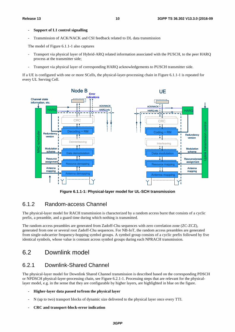
6.1.1 Uplink Shared Channel The physical-layer model for Uplink Shared Channel transmission is described based on the corresponding physical-layer-processing chain, see Figure 6.1.1-1. Processing steps that are relevant for the physical-layer model, e.g. in the sense that they are configurable by higher layers, are highlighted in blue. It should be noted that, in the cases of PUSCH and NPUSCH, the scheduling decision is fully done at the network side. The uplink transmission control in the UE then configures the uplink physical-layer processing, based on uplink transport-format and resource-assignment information received on the downlink.
- Higher-layer data passed to/from the physical layer
- One transport block of dynamic size delivered to the physical layer once every TTI.
- CRC and transport-block-error indication
- Transport-block-error indication delivered to higher layers.
- FEC and rate matching
- Channel coding rate is implicitly given by the combination of transport block size, modulation scheme and resource assignment;
- Physical layer model support of HARQ: in case of Incremental Redundancy, the corresponding Layer 2 Hybrid-ARQ process controls what redundancy version is to be used for the physical layer transmission for each TTI.
- Interleaving
- No control of interleaving by higher layers.
- Data modulation
- Modulation scheme is decided by MAC Scheduler (QPSK, 16QAM and 64QAM; for NB-IoT, supported modulation schemes are Pi/4-QPSK and Pi/2-BPSK for single-tone allocation, and QPSK for multi-tone allocation).
- Mapping to physical resource
- L2-controlled resource assignment.
- Multi-antenna processing
- MAC Scheduler partly configures mapping from assigned resource blocks to the available number of antenna ports.
3GPP
3GPP TS 36.302 V13.3.0 (2016-09 10 Release 13
- Support of L1 control signalling
- Transmission of ACK/NACK and CSI feedback related to DL data transmission
The model of Figure 6.1.1-1 also captures
- Transport via physical layer of Hybrid-ARQ related information associated with the PUSCH, to the peer HARQ process at the transmitter side;
- Transport via physical layer of corresponding HARQ acknowledgements to PUSCH transmitter side.
If a UE is configured with one or more SCells, the physical-layer-processing chain in Figure 6.1.1-1 is repeated for every UL Serving Cell.
CRC
RB mapping
Coding + RM
Data modulation
Interl.
CRC
Resource demapping
Decoding + RM
Data demodulation
Deinterleaving
MA
C s
ched
uler
Node B
Resourceassignment
Modulationscheme
Redundancyversion
Antennamapping
HARQ info
ACK/NACK
Antenna demapping
CRC
RB mapping
Coding + RM
Data modulation
Interl.
CRC
Resource mapping
Coding + RM
Data modulation
Interleaving
HARQ
UE
HARQ info
Antenna mapping
Errorindications
Resource/powerassignment
Modulationscheme
Antennamapping
HARQ
Upl
ink
tran
smis
sion
con
trol
Channel- state information, etc.
CRC
RB mapping
Coding + RM
Data modulation
Interl.
CRC
Resource demapping
Decoding + RM
Data demodulation
Deinterleaving
MA
C s
ched
uler
Node B
Resourceassignment
Modulationscheme
Redundancyversion
Antennamapping
HARQ info
ACK/NACK
Antenna demapping
CRC
RB mapping
Coding + RM
Data modulation
Interl.
CRC
Resource mapping
Coding + RM
Data modulation
Interleaving
HARQ
UE
HARQ info
Antenna mapping
Errorindications
Resource/powerassignment
Modulationscheme
Antennamapping
HARQ
Upl
ink
tran
smis
sion
con
trol
Channel- state information, etc.
Redundancyversion
Redundancyversion
ACK/NACKACK/NACK
Figure 6.1.1-1: Physical-layer model for UL-SCH transmission
6.1.2 Random-access Channel The physical-layer model for RACH transmission is characterized by a random access burst that consists of a cyclic prefix, a preamble, and a guard time during which nothing is transmitted.
The random access preambles are generated from Zadoff-Chu sequences with zero correlation zone (ZC-ZCZ), generated from one or several root Zadoff-Chu sequences. For NB-IoT, the random access preambles are generated from single-subcarrier frequency-hopping symbol groups. A symbol group consists of a cyclic prefix followed by five identical symbols, whose value is constant across symbol groups during each NPRACH transmission.
6.2 Downlink model
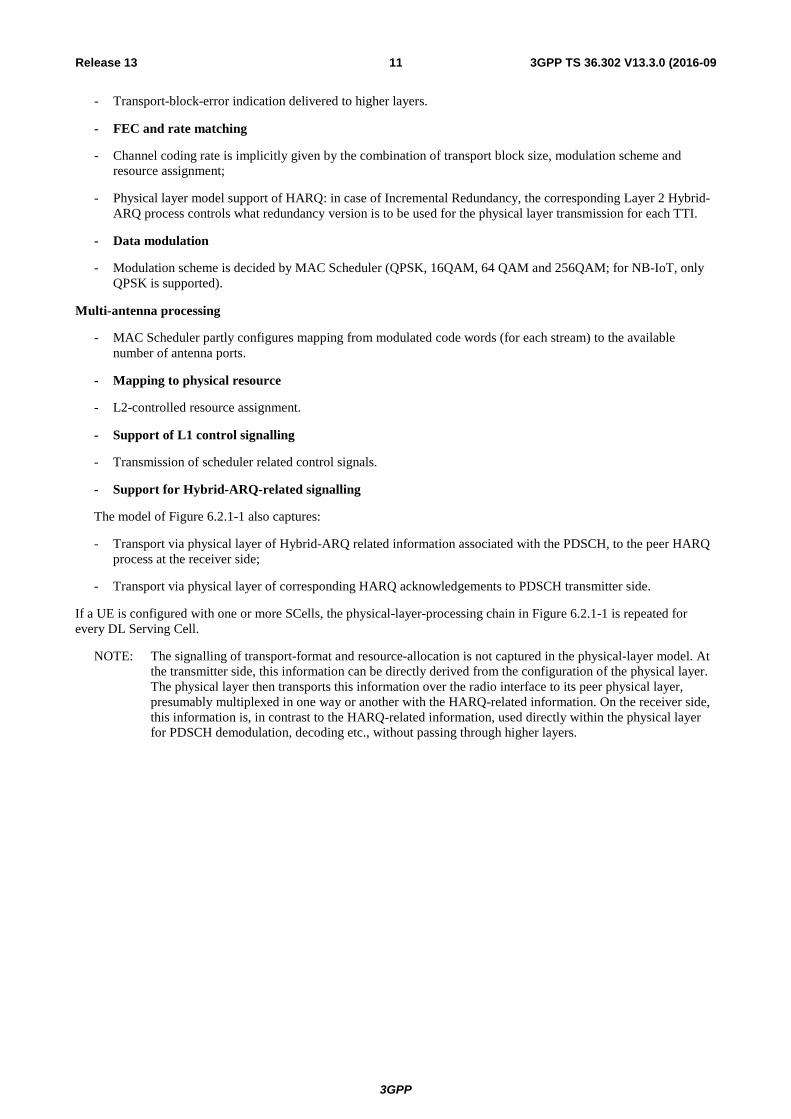
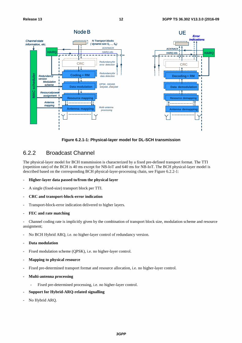
6.2.1 Downlink-Shared Channel The physical-layer model for Downlink Shared Channel transmission is described based on the corresponding PDSCH or NPDSCH physical-layer-processing chain, see Figure 6.2.1-1. Processing steps that are relevant for the physical-layer model, e.g. in the sense that they are configurable by higher layers, are highlighted in blue on the figure.
- Higher-layer data passed to/from the physical layer
- N (up to two) transport blocks of dynamic size delivered to the physical layer once every TTI.
- CRC and transport-block-error indication
3GPP
3GPP TS 36.302 V13.3.0 (2016-09 11 Release 13
- Transport-block-error indication delivered to higher layers.
- FEC and rate matching
- Channel coding rate is implicitly given by the combination of transport block size, modulation scheme and resource assignment;
- Physical layer model support of HARQ: in case of Incremental Redundancy, the corresponding Layer 2 Hybrid-ARQ process controls what redundancy version is to be used for the physical layer transmission for each TTI.
- Data modulation
- Modulation scheme is decided by MAC Scheduler (QPSK, 16QAM, 64 QAM and 256QAM; for NB-IoT, only QPSK is supported).
Multi-antenna processing
- MAC Scheduler partly configures mapping from modulated code words (for each stream) to the available number of antenna ports.
- Mapping to physical resource
- L2-controlled resource assignment.
- Support of L1 control signalling
- Transmission of scheduler related control signals.
- Support for Hybrid-ARQ-related signalling
The model of Figure 6.2.1-1 also captures:
- Transport via physical layer of Hybrid-ARQ related information associated with the PDSCH, to the peer HARQ process at the receiver side;
- Transport via physical layer of corresponding HARQ acknowledgements to PDSCH transmitter side.
If a UE is configured with one or more SCells, the physical-layer-processing chain in Figure 6.2.1-1 is repeated for every DL Serving Cell.
NOTE: The signalling of transport-format and resource-allocation is not captured in the physical-layer model. At the transmitter side, this information can be directly derived from the configuration of the physical layer. The physical layer then transports this information over the radio interface to its peer physical layer, presumably multiplexed in one way or another with the HARQ-related information. On the receiver side, this information is, in contrast to the HARQ-related information, used directly within the physical layer for PDSCH demodulation, decoding etc., without passing through higher layers.
3GPP
3GPP TS 36.302 V13.3.0 (2016-09 12 Release 13
CRC
RB mapping
Coding + RM
Data modulation
CRC
Resource mapping
Coding + RM
QPSK, 16QAM, 64QAM, 256QAMData modulation
HARQ
MA
C s
ched
uler
N Transport blocks( dynamicsize S1 ..., SN)
Node B
Redundancyfordata detection
Redundancyforerror detection
Multi- antennaprocessing
Resource/powerassignment
Modulationscheme
version
Antennamapping
HARQ info
ACK/NACK
Channel- stateinformation, etc.
Antenna mapping
CRC
RB mapping
Coding + RM
Data modulation
CRC
Resource demapping
Decoding + RM
Data demodulation
HARQ
UE
HARQ info
ACK/NACK
Antenna demapping
Errorindications
CRC
RB mapping
Coding + RM
Data modulation
CRC
Resource mapping
Coding + RM
Data modulation
HARQ
MA
C s
ched
uler
N Transport blocks( dynamicsize S1 ..., SN)
Node B
-
Resource/powerassignment
Modulationscheme
version
Antennamapping
Channel- stateinformation, etc.
Antenna mapping
CRC
RB mapping
Coding + RM
Data modulation
CRC
Resource demapping
Decoding + RM
Data demodulation
HARQ
UE
HARQ info
ACK/NACK
Antenna demapping
Errorindications
RedundancyRedundancy
Figure 6.2.1-1: Physical-layer model for DL-SCH transmission
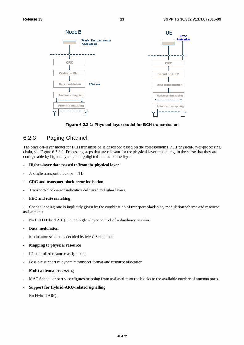
6.2.2 Broadcast Channel The physical-layer model for BCH transmission is characterized by a fixed pre-defined transport format. The TTI (repetition rate) of the BCH is 40 ms except for NB-IoT and 640 ms for NB-IoT. The BCH physical-layer model is described based on the corresponding BCH physical-layer-processing chain, see Figure 6.2.2-1:
- Higher-layer data passed to/from the physical layer
- A single (fixed-size) transport block per TTI.
- CRC and transport-block-error indication
- Transport-block-error indication delivered to higher layers.
- FEC and rate matching
- Channel coding rate is implicitly given by the combination of transport block size, modulation scheme and resource assignment;
- No BCH Hybrid ARQ, i.e. no higher-layer control of redundancy version.
- Data modulation
- Fixed modulation scheme (QPSK), i.e. no higher-layer control.
- Mapping to physical resource
- Fixed pre-determined transport format and resource allocation, i.e. no higher-layer control.
- Multi-antenna processing
- Fixed pre-determined processing, i.e. no higher-layer control.
- Support for Hybrid-ARQ-related signalling
- No Hybrid ARQ.
3GPP
3GPP TS 36.302 V13.3.0 (2016-09 13 Release 13
CRC
Resource mapping
Coding + RM
QPSK onlyData modulation
Single Transport blocks( fixed size S)
Node B
Antenna mapping
CRC
Resource demapping
Decoding+ RM
Data demodulation
UE
Antenna demapping
Errorindication
CRC
Resource mapping
Coding + RM
QPSK onlyData modulation
Single Transport blocks( fixed size S)
Node B
Antenna mapping
CRC
Resource demapping
Decoding+ RM
Data demodulation
UE
Antenna demapping
Errorindication
Figure 6.2.2-1: Physical-layer model for BCH transmission
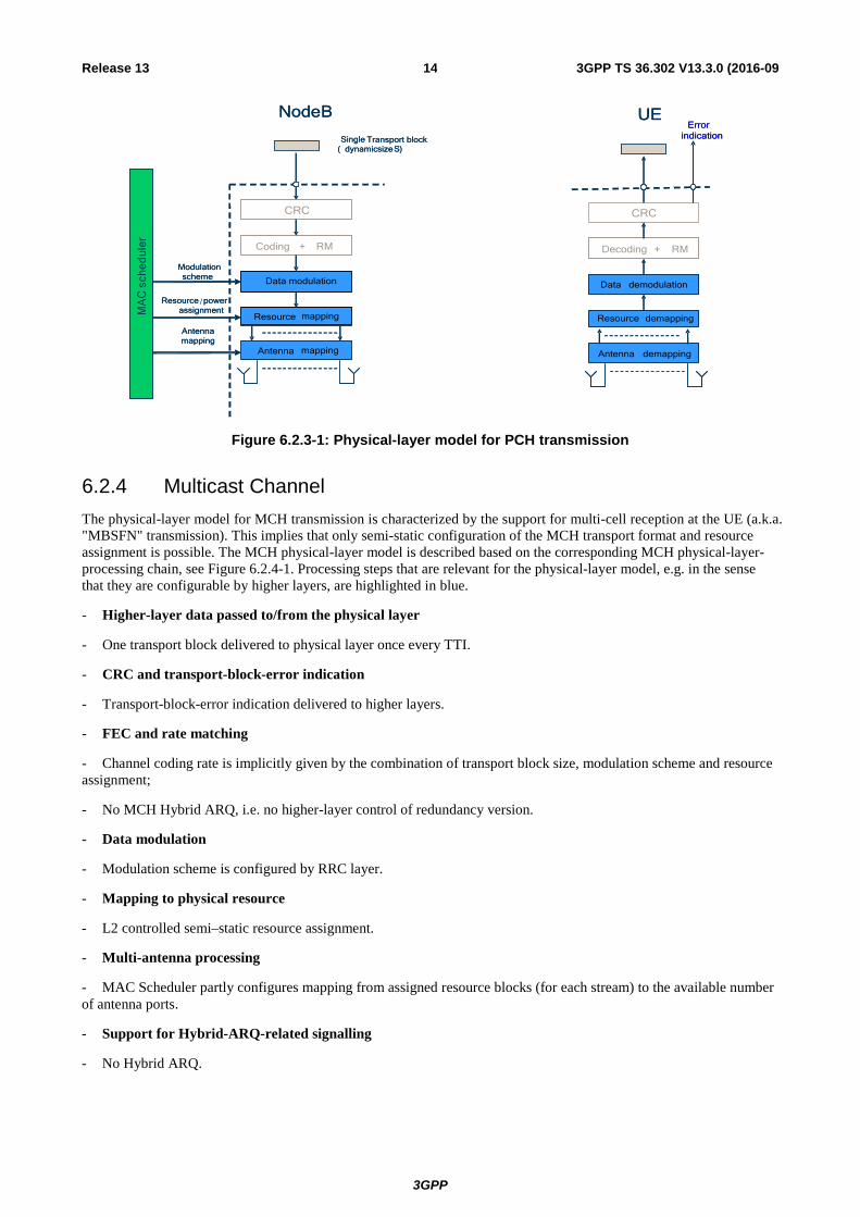
6.2.3 Paging Channel The physical-layer model for PCH transmission is described based on the corresponding PCH physical-layer-processing chain, see Figure 6.2.3-1. Processing steps that are relevant for the physical-layer model, e.g. in the sense that they are configurable by higher layers, are highlighted in blue on the figure.
- Higher-layer data passed to/from the physical layer
- A single transport block per TTI.
- CRC and transport-block-error indication
- Transport-block-error indication delivered to higher layers.
- FEC and rate matching
- Channel coding rate is implicitly given by the combination of transport block size, modulation scheme and resource assignment;
- No PCH Hybrid ARQ, i.e. no higher-layer control of redundancy version.
- Data modulation
- Modulation scheme is decided by MAC Scheduler.
- Mapping to physical resource
- L2 controlled resource assignment;
- Possible support of dynamic transport format and resource allocation.
- Multi-antenna processing
- MAC Scheduler partly configures mapping from assigned resource blocks to the available number of antenna ports.
- Support for Hybrid-ARQ-related signalling
No Hybrid ARQ.
3GPP
3GPP TS 36.302 V13.3.0 (2016-09 14 Release 13
CRC
Resource mapping
Coding + RM
Data modulation
MA
C s
ched
uler
Single Transport block( dynamicsizeS)
NodeB
Resource /powerassignment
Modulationscheme
Antennamapping
Antenna mapping
CRC
Resource demapping
Decoding + RM
Data demodulation
UE
Antenna demapping
Errorindication
MA
C s
ched
uler
Single Transport block( dynamicsizeS)
NodeB
Resource powerassignment
Modulationscheme
Antennamapping
UEError
indication
Figure 6.2.3-1: Physical-layer model for PCH transmission
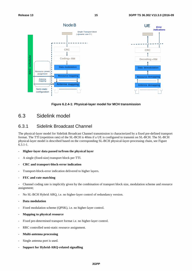
6.2.4 Multicast Channel The physical-layer model for MCH transmission is characterized by the support for multi-cell reception at the UE (a.k.a. "MBSFN" transmission). This implies that only semi-static configuration of the MCH transport format and resource assignment is possible. The MCH physical-layer model is described based on the corresponding MCH physical-layer-processing chain, see Figure 6.2.4-1. Processing steps that are relevant for the physical-layer model, e.g. in the sense that they are configurable by higher layers, are highlighted in blue.
- Higher-layer data passed to/from the physical layer
- One transport block delivered to physical layer once every TTI.
- CRC and transport-block-error indication
- Transport-block-error indication delivered to higher layers.
- FEC and rate matching
- Channel coding rate is implicitly given by the combination of transport block size, modulation scheme and resource assignment;
- No MCH Hybrid ARQ, i.e. no higher-layer control of redundancy version.
- Data modulation
- Modulation scheme is configured by RRC layer.
- Mapping to physical resource
- L2 controlled semi–static resource assignment.
- Multi-antenna processing
- MAC Scheduler partly configures mapping from assigned resource blocks (for each stream) to the available number of antenna ports.
- Support for Hybrid-ARQ-related signalling
- No Hybrid ARQ.
3GPP
3GPP TS 36.302 V13.3.0 (2016-09 15 Release 13
CRC
RB mapping
Coding Coding + RM
Data modulation
CRC
Resource mapping
Coding + RM
Data modulation
Single Transport block ( dynamic size S )
Node B
Resource / power assignment
Antenna mapping
Antenna mapping
CRC
RB mapping
Coding + RM
Data modulation
CRC
Resource demapping
Decoding + RM
Data demodulation
UE
Antenna mapping
CRC
RB mapping
Coding + RM
Data modulation
CRC
Resource demapping
Decoding + RM
Data demodulation
UE
Antenna demapping
Error indications
Semi - static configuration
MA
C s
ched
uler
Figure 6.2.4-1: Physical-layer model for MCH transmission
6.3 Sidelink model
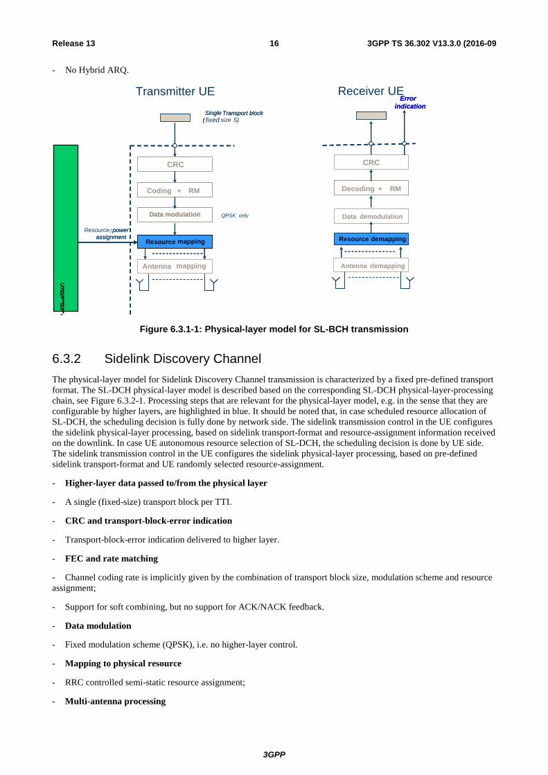
6.3.1 Sidelink Broadcast Channel The physical-layer model for Sidelink Broadcast Channel transmission is characterized by a fixed pre-defined transport format. The TTI (repetition rate) of the SL-BCH is 40ms if a UE is configured to transmit on SL-BCH. The SL-BCH physical-layer model is described based on the corresponding SL-BCH physical-layer-processing chain, see Figure 6.3.1-1.
- Higher-layer data passed to/from the physical layer
- A single (fixed-size) transport block per TTI.
- CRC and transport-block-error indication
- Transport-block-error indication delivered to higher layers.
- FEC and rate matching
- Channel coding rate is implicitly given by the combination of transport block size, modulation scheme and resource assignment;
- No SL-BCH Hybrid ARQ, i.e. no higher-layer control of redundancy version.
- Data modulation
- Fixed modulation scheme (QPSK), i.e. no higher-layer control.
- Mapping to physical resource
- Fixed pre-determined transport format i.e. no higher-layer control.
- RRC controlled semi-static resource assignment.
- Multi-antenna processing
- Single antenna port is used.
- Support for Hybrid-ARQ-related signalling
3GPP
3GPP TS 36.302 V13.3.0 (2016-09 16 Release 13
- No Hybrid ARQ.
Data modulation
Transmitter UE
QPSK onlyData modulation
fixed
Antenna mapping
Data demodulation
Antenna demapping
Receiver UE
Sidelink Trans
CRC
Resource mapping
Coding + RM
Single Transport block(
Resource /powerassignment
CRC
Resource demapping
Decoding + RM
Errorindication
Single Transport block( size S)
powerassignment
Errorindication
Figure 6.3.1-1: Physical-layer model for SL-BCH transmission
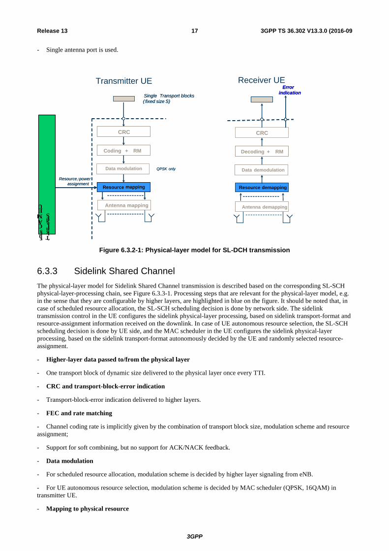
6.3.2 Sidelink Discovery Channel The physical-layer model for Sidelink Discovery Channel transmission is characterized by a fixed pre-defined transport format. The SL-DCH physical-layer model is described based on the corresponding SL-DCH physical-layer-processing chain, see Figure 6.3.2-1. Processing steps that are relevant for the physical-layer model, e.g. in the sense that they are configurable by higher layers, are highlighted in blue. It should be noted that, in case scheduled resource allocation of SL-DCH, the scheduling decision is fully done by network side. The sidelink transmission control in the UE configures the sidelink physical-layer processing, based on sidelink transport-format and resource-assignment information received on the downlink. In case UE autonomous resource selection of SL-DCH, the scheduling decision is done by UE side. The sidelink transmission control in the UE configures the sidelink physical-layer processing, based on pre-defined sidelink transport-format and UE randomly selected resource-assignment.
- Higher-layer data passed to/from the physical layer
- A single (fixed-size) transport block per TTI.
- CRC and transport-block-error indication
- Transport-block-error indication delivered to higher layer.
- FEC and rate matching
- Channel coding rate is implicitly given by the combination of transport block size, modulation scheme and resource assignment;
- Support for soft combining, but no support for ACK/NACK feedback.
- Data modulation
- Fixed modulation scheme (QPSK), i.e. no higher-layer control.
- Mapping to physical resource
- RRC controlled semi-static resource assignment;
- Multi-antenna processing
3GPP
3GPP TS 36.302 V13.3.0 (2016-09 17 Release 13
- Single antenna port is used.
CRC
Resource mapping
Coding + RM
Resource /powerassignment
CRC
Resource demapping
Decoding + RM
Errorindication
Transmitter UE
Resource powerassignment
Receiver UEError
indication
QPSK onlyData modulation
Single Transport blocks( fixed size S)
Antenna mapping
Data demodulation
Antenna demapping
QPSK onlyData modulation
Single Transport blocks( fixed size S)
Antenna mapping
Data demodulation
Antenna demapping
UE MAC sche
Sidelink Trans
Figure 6.3.2-1: Physical-layer model for SL-DCH transmission
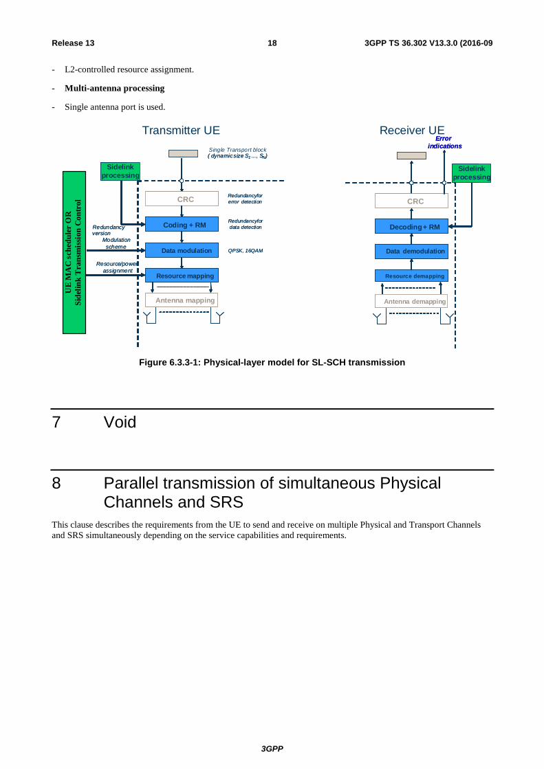
6.3.3 Sidelink Shared Channel The physical-layer model for Sidelink Shared Channel transmission is described based on the corresponding SL-SCH physical-layer-processing chain, see Figure 6.3.3-1. Processing steps that are relevant for the physical-layer model, e.g. in the sense that they are configurable by higher layers, are highlighted in blue on the figure. It should be noted that, in case of scheduled resource allocation, the SL-SCH scheduling decision is done by network side. The sidelink transmission control in the UE configures the sidelink physical-layer processing, based on sidelink transport-format and resource-assignment information received on the downlink. In case of UE autonomous resource selection, the SL-SCH scheduling decision is done by UE side, and the MAC scheduler in the UE configures the sidelink physical-layer processing, based on the sidelink transport-format autonomously decided by the UE and randomly selected resource-assignment.
- Higher-layer data passed to/from the physical layer
- One transport block of dynamic size delivered to the physical layer once every TTI.
- CRC and transport-block-error indication
- Transport-block-error indication delivered to higher layers.
- FEC and rate matching
- Channel coding rate is implicitly given by the combination of transport block size, modulation scheme and resource assignment;
- Support for soft combining, but no support for ACK/NACK feedback.
- Data modulation
- For scheduled resource allocation, modulation scheme is decided by higher layer signaling from eNB.
- For UE autonomous resource selection, modulation scheme is decided by MAC scheduler (QPSK, 16QAM) in transmitter UE.
- Mapping to physical resource
3GPP
3GPP TS 36.302 V13.3.0 (2016-09 18 Release 13
- L2-controlled resource assignment.
- Multi-antenna processing
- Single antenna port is used.
CRC
RB mapping
Coding + RM
Data modulation
CRC
Resource mapping
Coding + RM
QPSK, 16QAMData modulation
HARQ
( dynamicsize S1 ..., SN)
Redundancyfordata detection
Redundancyforerror detection
Resource/powerassignment
Modulationscheme
version
CRC
RB mapping
Coding + RM
Data modulation
CRC
Resource demapping
Decoding+ RM
Data demodulation
Errorindications
CRC
RB mapping
Coding + RM
Data modulation
CRC
Resource mapping
Coding + RM
QPSK, 16QAMData modulation
Sidelink processing
Single Transport block( dynamicsize S1 ..., SN)
Transmitter UE
Redundancyfordata detection
Redundancyforerror detection
Resource/powerassignment
Modulationscheme
version
CRC
RB mapping
Coding + RM
Data modulation
CRC
Resource demapping
Decoding+ RM
Data demodulation
Receiver UEError
indications
RedundancyRedundancy
Antenna mapping Antenna demappingAntenna mapping Antenna demapping
HARQSidelink
processing
UE
MA
C s
ched
uler
OR
Side
link
Tra
nsm
issi
on C
ontr
ol
Figure 6.3.3-1: Physical-layer model for SL-SCH transmission
7 Void
8 Parallel transmission of simultaneous Physical Channels and SRS
This clause describes the requirements from the UE to send and receive on multiple Physical and Transport Channels and SRS simultaneously depending on the service capabilities and requirements.
3GPP
3GPP TS 36.302 V13.3.0 (2016-09 19 Release 13
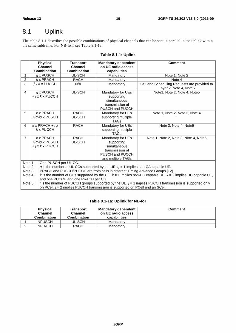
8.1 Uplink The table 8.1-1 describes the possible combinations of physical channels that can be sent in parallel in the uplink within the same subframe. For NB-IoT, see Table 8.1-1a.
Table 8.1-1: Uplink
Physical Channel
Combination
Transport Channel
Combination
Mandatory dependent on UE radio access
capabilities
Comment
1 q x PUSCH UL-SCH Mandatory Note 1, Note 2 2 k x PRACH RACH Mandatory Note 4 3 j x k x PUCCH N/A Mandatory CSI and Scheduling Requests are provided to
Layer 2. Note 4, Note5 4 q x PUSCH
+ j x k x PUCCH UL-SCH Mandatory for UEs
supporting simultaneous
transmission of PUSCH and PUCCH
Note1, Note 2, Note 4, Note5
5 k x PRACH +(q-k) x PUSCH
RACH UL-SCH
Mandatory for UEs supporting multiple
TAGs
Note 1, Note 2, Note 3, Note 4
6 k x PRACH + j x k x PUCCH
RACH Mandatory for UEs supporting multiple
TAGs
Note 3, Note 4, Note5
7 k x PRACH +(q-k) x PUSCH + j x k x PUCCH
RACH UL-SCH
Mandatory for UEs supporting
simultaneous transmission of
PUSCH and PUCCH and multiple TAGs
Note 1, Note 2, Note 3, Note 4, Note5
Note 1: One PUSCH per UL CC. Note 2: q is the number of UL CCs supported by the UE. q = 1 implies non-CA capable UE. Note 3: PRACH and PUSCH/PUCCH are from cells in different Timing Advance Groups [12]. Note 4: k is the number of CGs supported by the UE. k = 1 implies non-DC capable UE. k = 2 implies DC capable UE,
and one PUCCH and one PRACH per CG. Note 5: j is the number of PUCCH groups supported by the UE. j = 1 implies PUCCH transmission is supported only
on PCell. j = 2 implies PUCCH transmission is supported on PCell and an SCell.
Table 8.1-1a: Uplink for NB-IoT
Physical Channel
Combination
Transport Channel
Combination
Mandatory dependent on UE radio access
capabilities
Comment
1 NPUSCH UL-SCH Mandatory 2 NPRACH RACH Mandatory
3GPP
3GPP TS 36.302 V13.3.0 (2016-09 20 Release 13
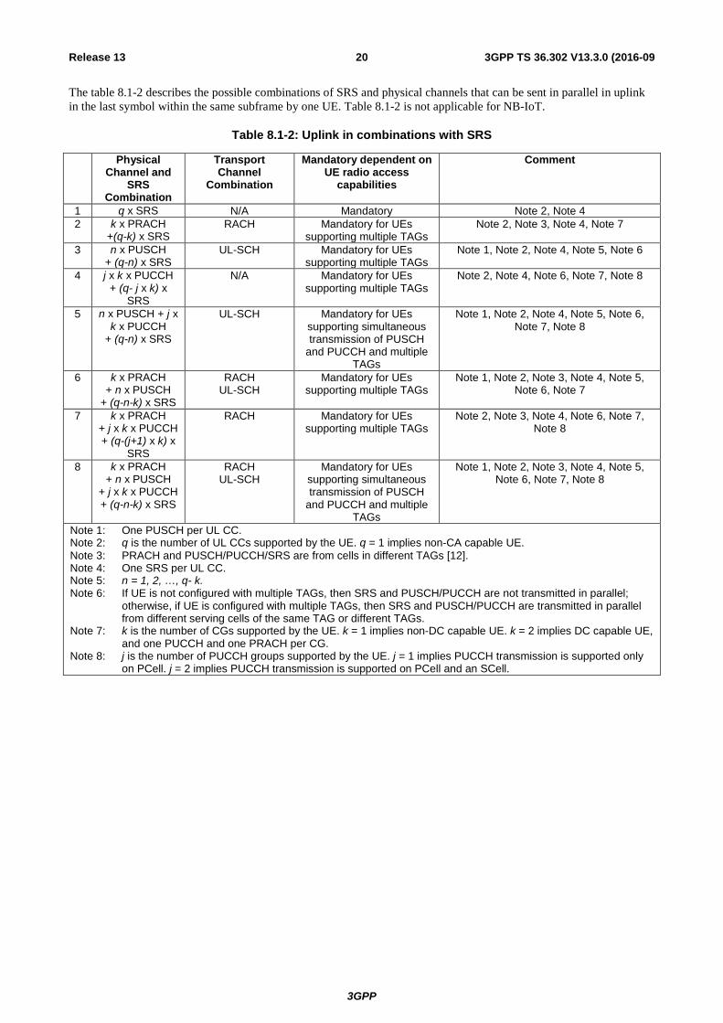
The table 8.1-2 describes the possible combinations of SRS and physical channels that can be sent in parallel in uplink in the last symbol within the same subframe by one UE. Table 8.1-2 is not applicable for NB-IoT.
Table 8.1-2: Uplink in combinations with SRS
Physical Channel and
SRS Combination
Transport Channel
Combination
Mandatory dependent on UE radio access
capabilities
Comment
1 q x SRS N/A Mandatory Note 2, Note 4 2 k x PRACH
+(q-k) x SRS RACH Mandatory for UEs
supporting multiple TAGs Note 2, Note 3, Note 4, Note 7
3 n x PUSCH + (q-n) x SRS
UL-SCH Mandatory for UEs supporting multiple TAGs
Note 1, Note 2, Note 4, Note 5, Note 6
4 j x k x PUCCH + (q- j x k) x
SRS
N/A Mandatory for UEs supporting multiple TAGs
Note 2, Note 4, Note 6, Note 7, Note 8
5 n x PUSCH + j x k x PUCCH
+ (q-n) x SRS
UL-SCH Mandatory for UEs supporting simultaneous transmission of PUSCH
and PUCCH and multiple TAGs
Note 1, Note 2, Note 4, Note 5, Note 6, Note 7, Note 8
6 k x PRACH + n x PUSCH
+ (q-n-k) x SRS
RACH UL-SCH
Mandatory for UEs supporting multiple TAGs
Note 1, Note 2, Note 3, Note 4, Note 5, Note 6, Note 7
7 k x PRACH + j x k x PUCCH + (q-(j+1) x k) x
SRS
RACH Mandatory for UEs supporting multiple TAGs
Note 2, Note 3, Note 4, Note 6, Note 7, Note 8
8 k x PRACH + n x PUSCH
+ j x k x PUCCH + (q-n-k) x SRS
RACH UL-SCH
Mandatory for UEs supporting simultaneous transmission of PUSCH
and PUCCH and multiple TAGs
Note 1, Note 2, Note 3, Note 4, Note 5, Note 6, Note 7, Note 8
Note 1: One PUSCH per UL CC. Note 2: q is the number of UL CCs supported by the UE. q = 1 implies non-CA capable UE. Note 3: PRACH and PUSCH/PUCCH/SRS are from cells in different TAGs [12]. Note 4: One SRS per UL CC. Note 5: n = 1, 2, …, q- k. Note 6: If UE is not configured with multiple TAGs, then SRS and PUSCH/PUCCH are not transmitted in parallel;
otherwise, if UE is configured with multiple TAGs, then SRS and PUSCH/PUCCH are transmitted in parallel from different serving cells of the same TAG or different TAGs.
Note 7: k is the number of CGs supported by the UE. k = 1 implies non-DC capable UE. k = 2 implies DC capable UE, and one PUCCH and one PRACH per CG.
Note 8: j is the number of PUCCH groups supported by the UE. j = 1 implies PUCCH transmission is supported only on PCell. j = 2 implies PUCCH transmission is supported on PCell and an SCell.
3GPP
3GPP TS 36.302 V13.3.0 (2016-09 21 Release 13
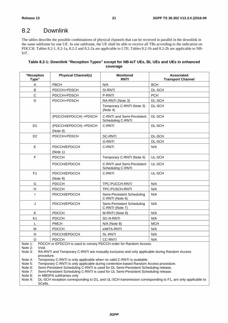
8.2 Downlink The tables describe the possible combinations of physical channels that can be received in parallel in the downlink in the same subframe by one UE. In one subframe, the UE shall be able to receive all TBs according to the indication on PDCCH. Tables 8.2-1, 8.2-1a, 8.2-2 and 8.2-2a are applicable to LTE; Tables 8.2-1b and 8.2-2b are applicable to NB-IoT.
Table 8.2-1: Downlink "Reception Types" except for NB-IoT UEs, BL UEs and UEs in enhanced coverage
"Reception Type"
Physical Channel(s) Monitored RNTI
Associated Transport Channel
A PBCH N/A BCH B PDCCH+PDSCH SI-RNTI DL-SCH C PDCCH+PDSCH P-RNTI PCH D PDCCH+PDSCH RA-RNTI (Note 3) DL-SCH
Temporary C-RNTI (Note 3) (Note 4)
DL-SCH
(PDCCH/EPDCCH) +PDSCH C-RNTI and Semi-Persistent Scheduling C-RNTI
DL-SCH
D1 (PDCCH/EPDCCH) +PDSCH (Note 9)
C-RNTI DL-SCH
D2 PDCCH+PDSCH SC-RNTI DL-SCH G-RNTI DL-SCH
E PDCCH/EPDCCH (Note 1)
C-RNTI N/A
F PDCCH Temporary C-RNTI (Note 5) UL-SCH
PDCCH/EPDCCH C-RNTI and Semi-Persistent Scheduling C-RNTI
UL-SCH
F1 PDCCH/EPDCCH (Note 9)
C-RNTI UL-SCH
G PDCCH TPC-PUCCH-RNTI N/A H PDCCH TPC-PUSCH-RNTI N/A I PDCCH/EPDCCH Semi-Persistent Scheduling
C-RNTI (Note 6) N/A
J PDCCH/EPDCCH Semi-Persistent Scheduling C-RNTI (Note 7)
N/A
K PDCCH M-RNTI (Note 8) N/A K1 PDCCH SC-N-RNTI N/A L PMCH N/A (Note 8) MCH M PDCCH eIMTA-RNTI N/A N PDCCH/EPDCCH SL-RNTI N/A O PDCCH CC-RNTI N/A
Note 1: PDCCH or EPDCCH is used to convey PDCCH order for Random Access. Note 2: Void. Note 3: RA-RNTI and Temporary C-RNTI are mutually exclusive and only applicable during Random Access
procedure. Note 4: Temporary C-RNTI is only applicable when no valid C-RNTI is available. Note 5: Temporary C-RNTI is only applicable during contention-based Random Access procedure. Note 6: Semi-Persistent Scheduling C-RNTI is used for DL Semi-Persistent Scheduling release. Note 7: Semi-Persistent Scheduling C-RNTI is used for UL Semi-Persistent Scheduling release. Note 8: In MBSFN subframes only Note 9: DL-SCH reception corresponding to D1, and UL-SCH transmission corresponding to F1, are only applicable to
SCells.
3GPP
3GPP TS 36.302 V13.3.0 (2016-09 22 Release 13
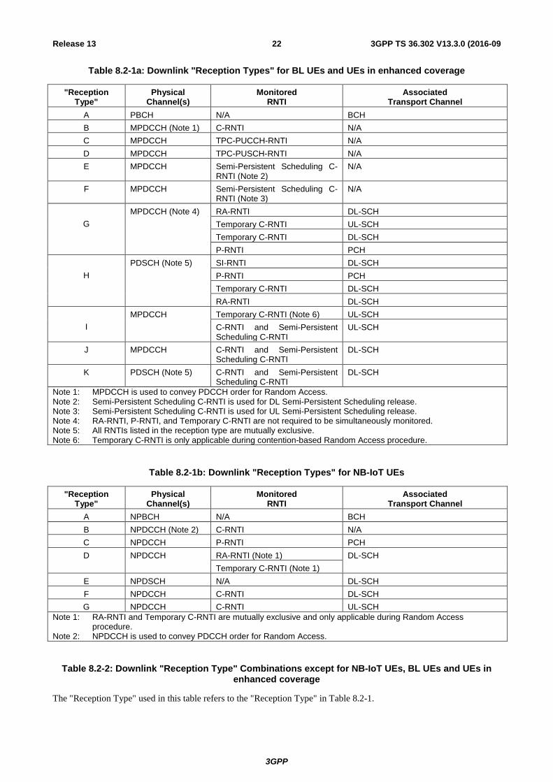
Table 8.2-1a: Downlink "Reception Types" for BL UEs and UEs in enhanced coverage
"Reception Type"
Physical Channel(s)
Monitored RNTI
Associated Transport Channel
A PBCH N/A BCH B MPDCCH (Note 1) C-RNTI N/A C MPDCCH TPC-PUCCH-RNTI N/A D MPDCCH TPC-PUSCH-RNTI N/A E MPDCCH Semi-Persistent Scheduling C-
RNTI (Note 2) N/A
F MPDCCH Semi-Persistent Scheduling C-RNTI (Note 3)
N/A
G
MPDCCH (Note 4) RA-RNTI DL-SCH Temporary C-RNTI UL-SCH Temporary C-RNTI DL-SCH P-RNTI PCH
H
PDSCH (Note 5) SI-RNTI DL-SCH P-RNTI PCH Temporary C-RNTI DL-SCH RA-RNTI DL-SCH
I
MPDCCH Temporary C-RNTI (Note 6) UL-SCH C-RNTI and Semi-Persistent Scheduling C-RNTI
UL-SCH
J MPDCCH C-RNTI and Semi-Persistent Scheduling C-RNTI
DL-SCH
K PDSCH (Note 5) C-RNTI and Semi-Persistent Scheduling C-RNTI
DL-SCH
Note 1: MPDCCH is used to convey PDCCH order for Random Access. Note 2: Semi-Persistent Scheduling C-RNTI is used for DL Semi-Persistent Scheduling release. Note 3: Semi-Persistent Scheduling C-RNTI is used for UL Semi-Persistent Scheduling release. Note 4: RA-RNTI, P-RNTI, and Temporary C-RNTI are not required to be simultaneously monitored. Note 5: All RNTIs listed in the reception type are mutually exclusive. Note 6: Temporary C-RNTI is only applicable during contention-based Random Access procedure.
Table 8.2-1b: Downlink "Reception Types" for NB-IoT UEs
"Reception Type"
Physical Channel(s)
Monitored RNTI
Associated Transport Channel
A NPBCH N/A BCH B NPDCCH (Note 2) C-RNTI N/A C NPDCCH P-RNTI PCH D NPDCCH RA-RNTI (Note 1) DL-SCH
Temporary C-RNTI (Note 1) E NPDSCH N/A DL-SCH F NPDCCH C-RNTI DL-SCH G NPDCCH C-RNTI UL-SCH
Note 1: RA-RNTI and Temporary C-RNTI are mutually exclusive and only applicable during Random Access procedure.
Note 2: NPDCCH is used to convey PDCCH order for Random Access.
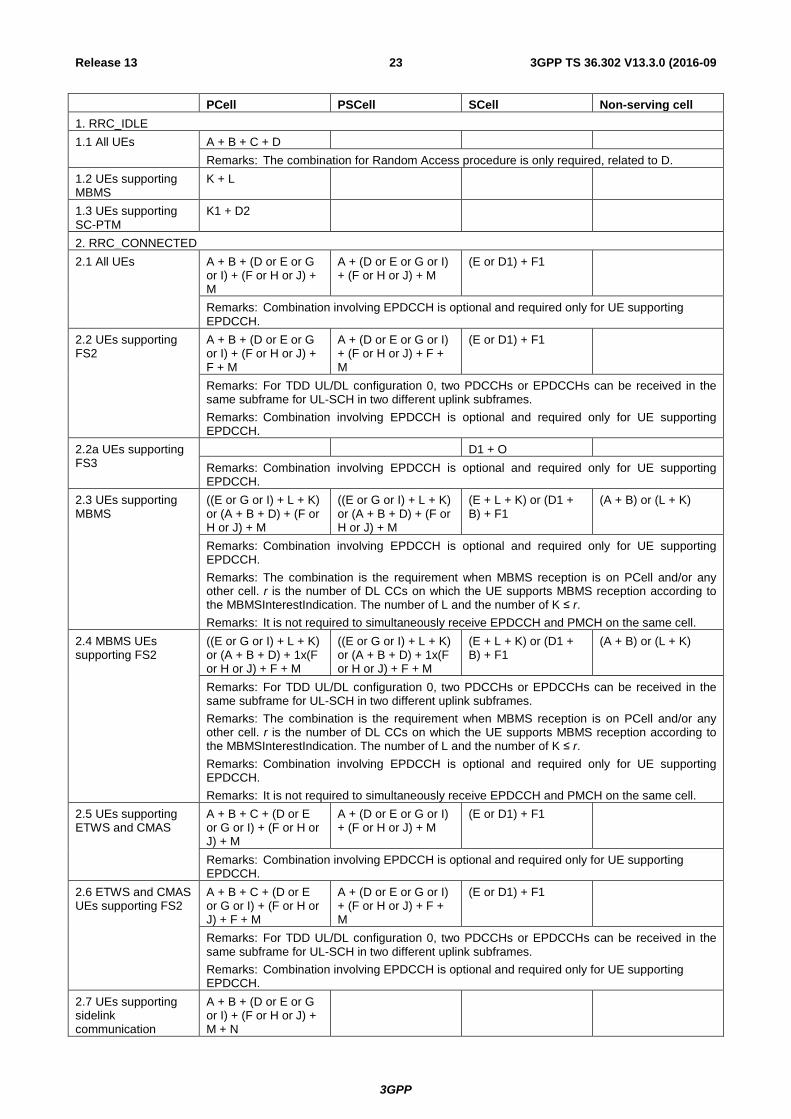
Table 8.2-2: Downlink "Reception Type" Combinations except for NB-IoT UEs, BL UEs and UEs in enhanced coverage
The "Reception Type" used in this table refers to the "Reception Type" in Table 8.2-1.
3GPP
3GPP TS 36.302 V13.3.0 (2016-09 23 Release 13
PCell PSCell SCell Non-serving cell 1. RRC_IDLE 1.1 All UEs A + B + C + D
Remarks: The combination for Random Access procedure is only required, related to D. 1.2 UEs supporting MBMS
K + L
1.3 UEs supporting SC-PTM
K1 + D2
2. RRC_CONNECTED 2.1 All UEs A + B + (D or E or G
or I) + (F or H or J) + M
A + (D or E or G or I) + (F or H or J) + M
(E or D1) + F1
Remarks: Combination involving EPDCCH is optional and required only for UE supporting EPDCCH.
2.2 UEs supporting FS2
A + B + (D or E or G or I) + (F or H or J) + F + M
A + (D or E or G or I) + (F or H or J) + F + M
(E or D1) + F1
Remarks: For TDD UL/DL configuration 0, two PDCCHs or EPDCCHs can be received in the same subframe for UL-SCH in two different uplink subframes. Remarks: Combination involving EPDCCH is optional and required only for UE supporting EPDCCH.
2.2a UEs supporting FS3
D1 + O Remarks: Combination involving EPDCCH is optional and required only for UE supporting EPDCCH.
2.3 UEs supporting MBMS
((E or G or I) + L + K) or (A + B + D) + (F or H or J) + M
((E or G or I) + L + K) or (A + B + D) + (F or H or J) + M
(E + L + K) or (D1 + B) + F1
(A + B) or (L + K)
Remarks: Combination involving EPDCCH is optional and required only for UE supporting EPDCCH. Remarks: The combination is the requirement when MBMS reception is on PCell and/or any other cell. r is the number of DL CCs on which the UE supports MBMS reception according to the MBMSInterestIndication. The number of L and the number of K ≤ r. Remarks: It is not required to simultaneously receive EPDCCH and PMCH on the same cell.
2.4 MBMS UEs supporting FS2
((E or G or I) + L + K) or (A + B + D) + 1x(F or H or J) + F + M
((E or G or I) + L + K) or (A + B + D) + 1x(F or H or J) + F + M
(E + L + K) or (D1 + B) + F1
(A + B) or (L + K)
Remarks: For TDD UL/DL configuration 0, two PDCCHs or EPDCCHs can be received in the same subframe for UL-SCH in two different uplink subframes. Remarks: The combination is the requirement when MBMS reception is on PCell and/or any other cell. r is the number of DL CCs on which the UE supports MBMS reception according to the MBMSInterestIndication. The number of L and the number of K ≤ r. Remarks: Combination involving EPDCCH is optional and required only for UE supporting EPDCCH. Remarks: It is not required to simultaneously receive EPDCCH and PMCH on the same cell.
2.5 UEs supporting ETWS and CMAS
A + B + C + (D or E or G or I) + (F or H or J) + M
A + (D or E or G or I) + (F or H or J) + M
(E or D1) + F1
Remarks: Combination involving EPDCCH is optional and required only for UE supporting EPDCCH.
2.6 ETWS and CMAS UEs supporting FS2
A + B + C + (D or E or G or I) + (F or H or J) + F + M
A + (D or E or G or I) + (F or H or J) + F + M
(E or D1) + F1
Remarks: For TDD UL/DL configuration 0, two PDCCHs or EPDCCHs can be received in the same subframe for UL-SCH in two different uplink subframes. Remarks: Combination involving EPDCCH is optional and required only for UE supporting EPDCCH.
2.7 UEs supporting sidelink communication
A + B + (D or E or G or I) + (F or H or J) + M + N
3GPP
3GPP TS 36.302 V13.3.0 (2016-09 24 Release 13
Remarks: Combination involving EPDCCH is optional and required only for UE supporting EPDCCH. Remarks: The combination is the requirement when the UE is configured in scheduled resource allocation mode.
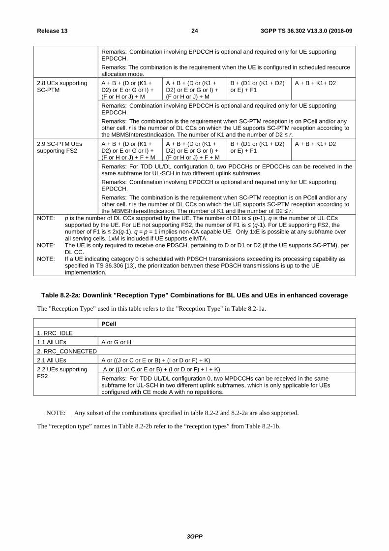
2.8 UEs supporting SC-PTM
A + B + (D or (K1 + D2) or E or G or I) + (F or H or J) + M
A + B + (D or (K1 + D2) or E or G or I) + (F or H or J) + M
B + (D1 or (K1 + D2) or E) + F1
A + B + K1+ D2
Remarks: Combination involving EPDCCH is optional and required only for UE supporting EPDCCH. Remarks: The combination is the requirement when SC-PTM reception is on PCell and/or any other cell. r is the number of DL CCs on which the UE supports SC-PTM reception according to the MBMSInterestIndication. The number of K1 and the number of D2 ≤ r.
2.9 SC-PTM UEs supporting FS2
A + B + (D or (K1 + D2) or E or G or I) + (F or H or J) + F + M
A + B + (D or (K1 + D2) or E or G or I) + (F or H or J) + F + M
B + (D1 or (K1 + D2) or E) + F1
A + B + K1+ D2
Remarks: For TDD UL/DL configuration 0, two PDCCHs or EPDCCHs can be received in the same subframe for UL-SCH in two different uplink subframes. Remarks: Combination involving EPDCCH is optional and required only for UE supporting EPDCCH. Remarks: The combination is the requirement when SC-PTM reception is on PCell and/or any other cell. r is the number of DL CCs on which the UE supports SC-PTM reception according to the MBMSInterestIndication. The number of K1 and the number of D2 ≤ r.
NOTE: p is the number of DL CCs supported by the UE. The number of D1 is ≤ (p-1). q is the number of UL CCs supported by the UE. For UE not supporting FS2, the number of F1 is ≤ (q-1). For UE supporting FS2, the number of F1 is ≤ 2x(q-1). q = p = 1 implies non-CA capable UE. Only 1xE is possible at any subframe over all serving cells. 1xM is included if UE supports eIMTA.
NOTE: The UE is only required to receive one PDSCH, pertaining to D or D1 or D2 (if the UE supports SC-PTM), per DL CC.
NOTE: If a UE indicating category 0 is scheduled with PDSCH transmissions exceeding its processing capability as specified in TS 36.306 [13], the prioritization between these PDSCH transmissions is up to the UE implementation.
Table 8.2-2a: Downlink "Reception Type" Combinations for BL UEs and UEs in enhanced coverage
The "Reception Type" used in this table refers to the "Reception Type" in Table 8.2-1a.
PCell 1. RRC_IDLE 1.1 All UEs A or G or H 2. RRC_CONNECTED 2.1 All UEs A or ((J or C or E or B) + (I or D or F) + K) 2.2 UEs supporting FS2
A or ((J or C or E or B) + (I or D or F) + I + K) Remarks: For TDD UL/DL configuration 0, two MPDCCHs can be received in the same subframe for UL-SCH in two different uplink subframes, which is only applicable for UEs configured with CE mode A with no repetitions.
NOTE: Any subset of the combinations specified in table 8.2-2 and 8.2-2a are also supported.
The “reception type” names in Table 8.2-2b refer to the “reception types” from Table 8.2-1b.
3GPP
3GPP TS 36.302 V13.3.0 (2016-09 25 Release 13
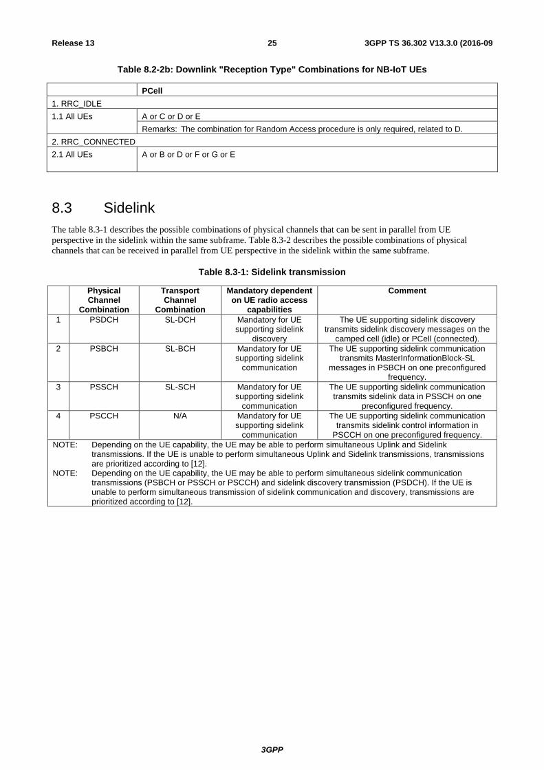
Table 8.2-2b: Downlink "Reception Type" Combinations for NB-IoT UEs
PCell 1. RRC_IDLE 1.1 All UEs A or C or D or E
Remarks: The combination for Random Access procedure is only required, related to D. 2. RRC_CONNECTED 2.1 All UEs A or B or D or F or G or E
8.3 Sidelink The table 8.3-1 describes the possible combinations of physical channels that can be sent in parallel from UE perspective in the sidelink within the same subframe. Table 8.3-2 describes the possible combinations of physical channels that can be received in parallel from UE perspective in the sidelink within the same subframe.
Table 8.3-1: Sidelink transmission
Physical Channel
Combination
Transport Channel
Combination
Mandatory dependent on UE radio access
capabilities
Comment
1 PSDCH SL-DCH Mandatory for UE supporting sidelink
discovery
The UE supporting sidelink discovery transmits sidelink discovery messages on the
camped cell (idle) or PCell (connected). 2 PSBCH SL-BCH Mandatory for UE
supporting sidelink communication
The UE supporting sidelink communication transmits MasterInformationBlock-SL
messages in PSBCH on one preconfigured frequency.
3 PSSCH SL-SCH Mandatory for UE supporting sidelink
communication
The UE supporting sidelink communication transmits sidelink data in PSSCH on one
preconfigured frequency. 4 PSCCH N/A Mandatory for UE
supporting sidelink communication
The UE supporting sidelink communication transmits sidelink control information in
PSCCH on one preconfigured frequency. NOTE: Depending on the UE capability, the UE may be able to perform simultaneous Uplink and Sidelink
transmissions. If the UE is unable to perform simultaneous Uplink and Sidelink transmissions, transmissions are prioritized according to [12].
NOTE: Depending on the UE capability, the UE may be able to perform simultaneous sidelink communication transmissions (PSBCH or PSSCH or PSCCH) and sidelink discovery transmission (PSDCH). If the UE is unable to perform simultaneous transmission of sidelink communication and discovery, transmissions are prioritized according to [12].
3GPP
3GPP TS 36.302 V13.3.0 (2016-09 26 Release 13
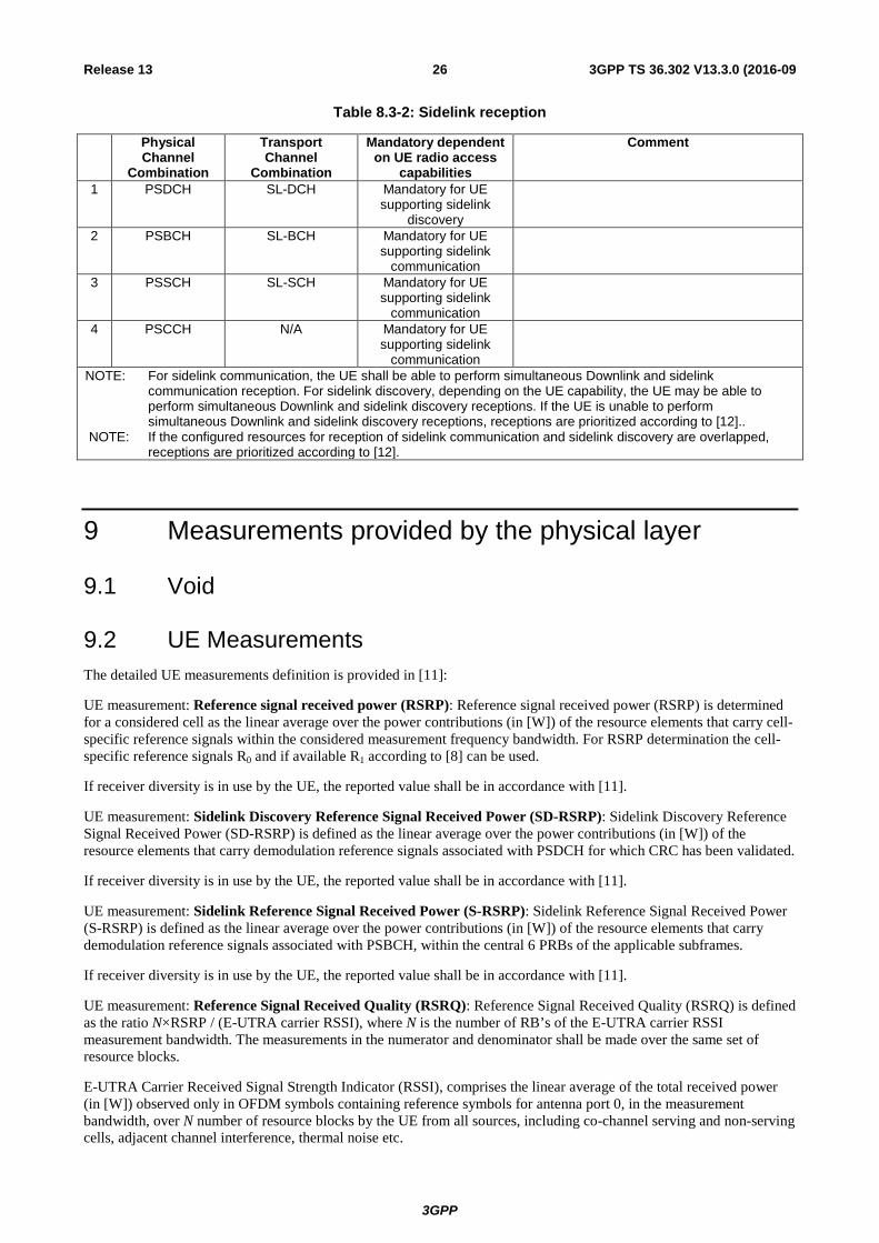
Table 8.3-2: Sidelink reception
Physical Channel
Combination
Transport Channel
Combination
Mandatory dependent on UE radio access
capabilities
Comment
1 PSDCH SL-DCH Mandatory for UE supporting sidelink
discovery
2 PSBCH SL-BCH Mandatory for UE supporting sidelink
communication
3 PSSCH SL-SCH Mandatory for UE supporting sidelink
communication
4 PSCCH N/A Mandatory for UE supporting sidelink
communication
NOTE: For sidelink communication, the UE shall be able to perform simultaneous Downlink and sidelink communication reception. For sidelink discovery, depending on the UE capability, the UE may be able to perform simultaneous Downlink and sidelink discovery receptions. If the UE is unable to perform simultaneous Downlink and sidelink discovery receptions, receptions are prioritized according to [12]..
NOTE: If the configured resources for reception of sidelink communication and sidelink discovery are overlapped, receptions are prioritized according to [12].
9 Measurements provided by the physical layer
9.1 Void
9.2 UE Measurements The detailed UE measurements definition is provided in [11]:
UE measurement: Reference signal received power (RSRP): Reference signal received power (RSRP) is determined for a considered cell as the linear average over the power contributions (in [W]) of the resource elements that carry cell-specific reference signals within the considered measurement frequency bandwidth. For RSRP determination the cell-specific reference signals R0 and if available R1 according to [8] can be used.
If receiver diversity is in use by the UE, the reported value shall be in accordance with [11].
UE measurement: Sidelink Discovery Reference Signal Received Power (SD-RSRP): Sidelink Discovery Reference Signal Received Power (SD-RSRP) is defined as the linear average over the power contributions (in [W]) of the resource elements that carry demodulation reference signals associated with PSDCH for which CRC has been validated.
If receiver diversity is in use by the UE, the reported value shall be in accordance with [11].
UE measurement: Sidelink Reference Signal Received Power (S-RSRP): Sidelink Reference Signal Received Power (S-RSRP) is defined as the linear average over the power contributions (in [W]) of the resource elements that carry demodulation reference signals associated with PSBCH, within the central 6 PRBs of the applicable subframes.
If receiver diversity is in use by the UE, the reported value shall be in accordance with [11].
UE measurement: Reference Signal Received Quality (RSRQ): Reference Signal Received Quality (RSRQ) is defined as the ratio N×RSRP / (E-UTRA carrier RSSI), where N is the number of RB’s of the E-UTRA carrier RSSI measurement bandwidth. The measurements in the numerator and denominator shall be made over the same set of resource blocks.
E-UTRA Carrier Received Signal Strength Indicator (RSSI), comprises the linear average of the total received power (in [W]) observed only in OFDM symbols containing reference symbols for antenna port 0, in the measurement bandwidth, over N number of resource blocks by the UE from all sources, including co-channel serving and non-serving cells, adjacent channel interference, thermal noise etc.
3GPP
3GPP TS 36.302 V13.3.0 (2016-09 27 Release 13
If receiver diversity is in use by the UE, the reported value shall be in accordance with [11].
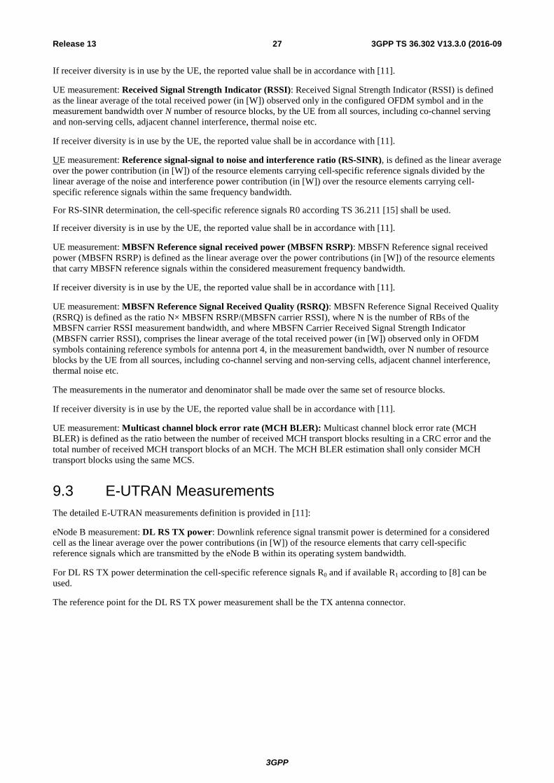
UE measurement: Received Signal Strength Indicator (RSSI): Received Signal Strength Indicator (RSSI) is defined as the linear average of the total received power (in [W]) observed only in the configured OFDM symbol and in the measurement bandwidth over N number of resource blocks, by the UE from all sources, including co-channel serving and non-serving cells, adjacent channel interference, thermal noise etc.
If receiver diversity is in use by the UE, the reported value shall be in accordance with [11].
UE measurement: Reference signal-signal to noise and interference ratio (RS-SINR), is defined as the linear average over the power contribution (in [W]) of the resource elements carrying cell-specific reference signals divided by the linear average of the noise and interference power contribution (in [W]) over the resource elements carrying cell-specific reference signals within the same frequency bandwidth.
For RS-SINR determination, the cell-specific reference signals R0 according TS 36.211 [15] shall be used.
If receiver diversity is in use by the UE, the reported value shall be in accordance with [11].
UE measurement: MBSFN Reference signal received power (MBSFN RSRP): MBSFN Reference signal received power (MBSFN RSRP) is defined as the linear average over the power contributions (in [W]) of the resource elements that carry MBSFN reference signals within the considered measurement frequency bandwidth.
If receiver diversity is in use by the UE, the reported value shall be in accordance with [11].
UE measurement: MBSFN Reference Signal Received Quality (RSRQ): MBSFN Reference Signal Received Quality (RSRQ) is defined as the ratio N× MBSFN RSRP/(MBSFN carrier RSSI), where N is the number of RBs of the MBSFN carrier RSSI measurement bandwidth, and where MBSFN Carrier Received Signal Strength Indicator (MBSFN carrier RSSI), comprises the linear average of the total received power (in [W]) observed only in OFDM symbols containing reference symbols for antenna port 4, in the measurement bandwidth, over N number of resource blocks by the UE from all sources, including co-channel serving and non-serving cells, adjacent channel interference, thermal noise etc.
The measurements in the numerator and denominator shall be made over the same set of resource blocks.
If receiver diversity is in use by the UE, the reported value shall be in accordance with [11].
UE measurement: Multicast channel block error rate (MCH BLER): Multicast channel block error rate (MCH BLER) is defined as the ratio between the number of received MCH transport blocks resulting in a CRC error and the total number of received MCH transport blocks of an MCH. The MCH BLER estimation shall only consider MCH transport blocks using the same MCS.
9.3 E-UTRAN Measurements The detailed E-UTRAN measurements definition is provided in [11]:
eNode B measurement: DL RS TX power: Downlink reference signal transmit power is determined for a considered cell as the linear average over the power contributions (in [W]) of the resource elements that carry cell-specific reference signals which are transmitted by the eNode B within its operating system bandwidth.
For DL RS TX power determination the cell-specific reference signals R0 and if available R1 according to [8] can be used.
The reference point for the DL RS TX power measurement shall be the TX antenna connector.
3GPP
3GPP TS 36.302 V13.3.0 (2016-09 28 Release 13
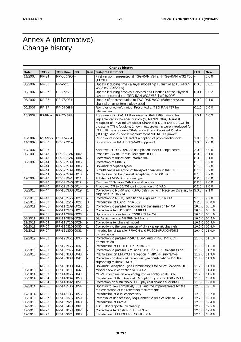
Annex A (informative): Change history
Change history Date TSG # TSG Doc. CR Rev Subject/Comment Old New 11/2006 RP-34 RP-060795 - First version : presented at TSG-RAN #34 and TSG-RAN WG2 #56
(11/2006) - 0.0.0
05/2007 RP-36 RP-xyztu Update including physical layer modelling: submitted at TSG-RAN WG2 #58 (05/2006)
0.0.0 0.0.1
06/2007 RP-37 R2-072502 Update including physical Services and functions of the Physical Layer: presented and TSG-RAN WG2 #58bis (06/2006)
0.0.1 0.0.2
06/2007 RP-37 R2-072931 Update after presentation at TSG-RAN WG2 #58bis : physical channel channel terminology used
0.0.2 0.1.0
09/2007 RP-37 RP-070686 Removal of editor’s notes. Presented at TSG-RAN #37 for information
0.1.0 1.0.0
10/2007 R2-59bis R2-074579 Agreements in RAN1 LS received at RAN2#59 have to be implemented in the specification (by RAN2#59bis): Parallel reception of Physical Broadcast Channel (PBCH) and DL-SCH in the same TTI is feasible; 2 new measurements were introduced for LTE, UE measurement "Reference Signal Received Quality (RSRQ)" and eNode B measurement "DL RS TX power".
1.0.1 1.0.2
10/2007 R2-59bis R2-074584 Removal of incorrect Parallel reception of physical channels 1.0.2 1.0.3 11/2007 RP-38 RP-070914
Submission to RAN for RAN#38 approval 1.0.3 2.0.0
12/2007 RP-38 - Apprpved at TSG RAN-38 and placed under change control 2.0.0 8.0.0 03/2009 RP-43 RP-090124 0002 - Proposed CR on Parallel reception in LTE 8.0.0 8.1.0 RP-43 RP-090124 0004 - Correction of out-of-date information 8.0.0 8.1.0 06/2009 RP-44 RP-090509 0005 1 Correction of MBMS 8.1.0 8.2.0 RP-44 RP-090509 0006 - Downlink reception types 8.1.0 8.2.0 RP-44 RP-090509 0009 - Simultaneous reception of transport channels in the LTE 8.1.0 8.2.0 RP-44 RP-090509 0010 - Clarification on the parallel receptions for PDSCHs 8.1.0 8.2.0 12/2009 RP-46 RP-091341 0011 - Addition of MBMS reception types 8.2.0 9.0.0 RP-46 RP-091346 0012 - Remove FFSs from RAN2 specifications 8.2.0 9.0.0 RP-46 RP-091345 0014 - Proposed CR to 36.302 on Introduction of CMAS 8.2.0 9.0.0 03/2010 RP-47 RP-100308 0019 1 Correction to RSRP and RSRQ definition with Receiver Diversity to
align with TS 36.214 9.0.0 9.1.0
06/2010 RP-48 RP-100556 0020 - Correction to RSRQ definition to align with TS 36.214 9.1.0 9.2.0 12/2010 RP-50 RP-101226 0021 3 Introduction of CA to TS36.302 9.2.0 10.0.0 03/2011 RP-51 RP-110289 0022 1 Correction to parallel reception and transmission for CA 10.0.0 10.1.0 RP-51 RP-110270 0025 - Corrections to TS36.302 on MBMS 10.0.0 10.1.0 RP-51 RP-110289 0026 - Update and correction to TS36.302 for CA 10.0.0 10.1.0 06/2011 RP-52 RP-110839 0028 - DL Assignment in MBSFN Subframe 10.1.0 10.2.0 12/2011 RP-54 RP-111716 0029 - Corrections to channel model 10.2.0 10.3.0 03/2012 RP-55 RP-120326 0030 1 Correction to the combination of physical uplink channels 10.3.0 10.4.0 09/2012 RP-57 RP-121350 0031 - Introduction of parallel PRACH and PUSCH/PUCCH/SRS
transmission 10.4.0 11.0.0
12/2012 RP-58 RP-121951 0036 - Correction to parallel PRACH, SRS and PUSCH/PUCCH transmission
11.0.0 11.1.0
RP-58 RP-121956 0037 - Introduction of EPDCCH in TS 36.302 11.0.0 11.1.0 03/2013 RP-59 RP-130245 0041 - Correction to parallel SRS and PUSCH/PUCCH transmission 11.1.0 11.2.0 06/2013 RP-60 RP-130808 0043 - Clarification on EPDCCH reception in MBSFN subframes 11.2.0 11.3.0 RP-60 RP-130808 0044 - Correction on downlink reception type combinations for UEs
supporting multiple TAGs 11.2.0 11.3.0
RP-60 RP-130808 0045 - Downlink Reception Type Combinations for MBMS capable UE 11.2.0 11.3.0 09/2013 RP-61 RP-131311 0047 - Miscellaneous correction to 36.302 11.3.0 11.4.0 03/2014 RP-63 RP-140355 0049 - MBMS reception on any configured or configurable SCell 11.4.0 11.5.0 06/2014 RP-64 RP-140884 0050 - Introduction of the Downlink Reception Types for TDD eIMTA 11.5.0 12.0.0 RP-64 RP-140892 0051 - Correction on simultaneous DL physical channels for idle UE 11.5.0 12.0.0 09/2014 RP-65 RP-141506 0054 1 Updates for low complexity UEs, and the improvements for the
representation of the reception requirements 12.0.0 12.1.0
12/2014 RP-66 RP-142135 0056 - Introduction of dual connectivity 12.1.0 12.2.0 03/2015 RP-67 RP-150376 0059 - Removal of unnecessary requirement to receive MIB on SCell 12.2.0 12.3.0 06/2015 RP-68 RP-150921 0060 - Introduction of ProSe 12.3.0 12.4.0 09/2015 RP-69 RP-151443 0061 1 TS36.302 rapporteur's cleanup 12.4.0 12.5.0 12/2015 RP-70 RP-152053 0062 - Corrections to Sidelink in TS 36.302 12.5.0 12.6.0 12/2015 RP-70 RP-152071 0063 - Introduction of PUCCH on SCell in CA 12.6.0 13.0.0
3GPP
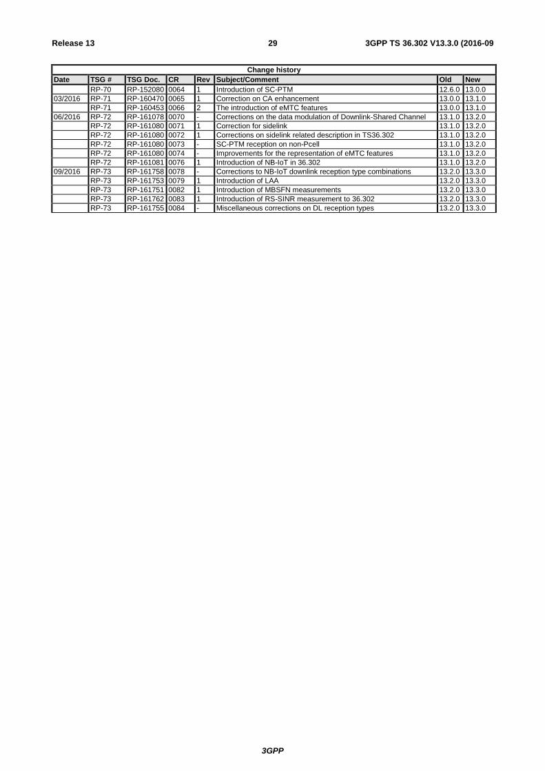
3GPP TS 36.302 V13.3.0 (2016-09 29 Release 13
Change history Date TSG # TSG Doc. CR Rev Subject/Comment Old New RP-70 RP-152080 0064 1 Introduction of SC-PTM 12.6.0 13.0.0 03/2016 RP-71 RP-160470 0065 1 Correction on CA enhancement 13.0.0 13.1.0 RP-71 RP-160453 0066 2 The introduction of eMTC features 13.0.0 13.1.0 06/2016 RP-72 RP-161078 0070 - Corrections on the data modulation of Downlink-Shared Channel 13.1.0 13.2.0 RP-72 RP-161080 0071 1 Correction for sidelink 13.1.0 13.2.0 RP-72 RP-161080 0072 1 Corrections on sidelink related description in TS36.302 13.1.0 13.2.0 RP-72 RP-161080 0073 - SC-PTM reception on non-Pcell 13.1.0 13.2.0 RP-72 RP-161080 0074 - Improvements for the representation of eMTC features 13.1.0 13.2.0 RP-72 RP-161081 0076 1 Introduction of NB-IoT in 36.302 13.1.0 13.2.0 09/2016 RP-73 RP-161758 0078 - Corrections to NB-IoT downlink reception type combinations 13.2.0 13.3.0 RP-73 RP-161753 0079 1 Introduction of LAA 13.2.0 13.3.0 RP-73 RP-161751 0082 1 Introduction of MBSFN measurements 13.2.0 13.3.0 RP-73 RP-161762 0083 1 Introduction of RS-SINR measurement to 36.302 13.2.0 13.3.0 RP-73 RP-161755 0084 - Miscellaneous corrections on DL reception types 13.2.0 13.3.0