Embed Size (px)
Citation preview
TSG-RAN Plenary meeting #5 TSGR#5(99)443Korea, October 1999
Agenda Item:
Source: Editor
Title: 25.410, UTRAN Iu Interface, General Aspects and Principles
Document for: Approval (to v.3.0.0)
___________________________________________________________________________
This document contains (as marked changes) the modifications agreed during the finalreview in RAN3.

3GPP
TS 25.410 V2.0.0 (1999-09)Technical Specification
3rd Generation Partnership Project (3GPP);Technical Specification Group (TSG) RAN;
UTRAN Iu Interface: General Aspects and Principles
UMTS 25.410
<
3GPP
TS 25.410 V2.0.0 (1999-09)4UMTS 25.410
Reference<Workitem> (<Shortfilename>.PDF)
Keywords<keyword[, keyword]>
3GPP
Postal address
Office address
Individual copies of this deliverablecan be downloaded fromhttp://www.3gpp.org
Copyright Notification
No part may be reproduced except as authorized by written permission.The copyright and the foregoing restriction extend to reproduction in all media.
©All rights reserved.
3GPP
TS 25.410 V2.0.0 (1999-09)5UMTS 25.410
Contents
1 SCOPE.......................................................................................................................................................................8
2 REFERENCES..........................................................................................................................................................8
3 DEFINITIONS AND ABBREVIATIONS ..............................................................................................................8
3.1 DEFINITIONS ........................................................................................................................................................83.2 ABBREVIATIONS ..................................................................................................................................................8
4 GENERAL ASPECTS..............................................................................................................................................9
4.1 UTRAN ARCHITECTURE ....................................................................................................................................94.1.1 Iu Interface Architecture....................................................................................................................................94.1.2 Iu connection principles...................................................................................................................................10
4.2 IU INTERFACE GENERAL PRINCIPLES .................................................................................................................104.3 IU INTERFACE SPECIFICATION OBJECTIVES........................................................................................................114.4 IU INTERFACE CAPABILITIES ..............................................................................................................................114.5 IU INTERFACE CHARACTERISTICS .......................................................................................................................12
4.5.1 Use of Transport Network User Plane as Signalling Bearer...........................................................................124.5.1.1 Use of SCCP ................................................................................................................................................................12
4.5.1.1.1 General..................................................................................................................................................................124.5.1.1.2 SCCP connection establishment ...........................................................................................................................12
4.5.1.1.2.1 Establishment procedure in case i ............................................................................................................124.5.1.1.2.2 Establishment procedure in case ii ...........................................................................................................13
4.5.1.1.3 SCCP connection release .................................................................................................................................144.5.1.1.4 General SCCP Abnormal Conditions...............................................................................................................14
4.5.2 Use of Transport Network User Plane as User Data Bearer...........................................................................144.5.2.1 Use of AAL2 ................................................................................................................................................................144.5.2.2 Use of GTP-U ..............................................................................................................................................................14
5 FUNCTIONS OF THE IU INTERFACE PROTOCOLS & FUNCTIONAL SPLIT ........................................14
5.1 GENERAL .................................................................................................................................................................145.2 RAB MANAGEMENT FUNCTIONS .............................................................................................................................16
5.2.1 RAB establishment, modification and release function....................................................................................165.2.2 RAB characteristics mapping to Uu bearers function .....................................................................................165.2.3 RAB characteristics mapping to Iu transport bearers .....................................................................................165.2.4 RAB queuing, pre-emption and priority function ............................................................................................165.3 Radio Resource Management over Iu.................................................................................................................165.3.1 Radio resource admission control ...................................................................................................................165.3.2 Broadcast information management................................................................................................................17
5.4 RATE ADAPTATION FOR EXTERNAL NETWORKS ........................................................................................................175.5 IU LINK MANAGEMENT FUNCTIONS .........................................................................................................................17
5.5.1 Iu Signalling Link Management function.........................................................................................................175.5.2 ATM Virtual Connection Management function..............................................................................................175.5.3 AAL2 connection establish and release function .............................................................................................175.5.4 AAL5 management function.............................................................................................................................185.5.5 GTP-U tunnels management function..............................................................................................................185.5.6 Buffer Management..........................................................................................................................................18
5.6 IU U-PLANE (RNL)MANAGEMENT FUNCTIONS........................................................................................................185.6.1 Iu U-plane frame protocol mode selection function ........................................................................................185.6.2 Iu U-plane frame protocol initialization..........................................................................................................18
5.7 MOBILITY MANAGEMENT FUNCTIONS .....................................................................................................................185.7.1 Mobility Management ......................................................................................................................................185.7.2 Location information update function .............................................................................................................185.7.3 Handover and Relocation functions ................................................................................................................19
5.7.3.1 Active Cell Management, intra RNC ...........................................................................................................................195.7.3.2 Active Cell Management, inter RNC, when Iur is available ........................................................................................195.7.3.3 Inter RNC hard HO function, Iur not used or not available .........................................................................................195.7.3.4 Serving RNS Relocation function ................................................................................................................................195.7.3.5 Inter system Handover (e.g. GSM-UMTS) function ....................................................................................................19
3GPP
TS 25.410 V2.0.0 (1999-09)6UMTS 25.410
5.7.4 Paging..............................................................................................................................................................195.7.4.1 Paging triggering function............................................................................................................................................195.7.4.2 Paging execution function............................................................................................................................................19
5.7.5 Location Management .....................................................................................................................................195.8 SECURITY FUNCTIONS .............................................................................................................................................20
5.8.1 Data Confidentiality ........................................................................................................................................205.8.1.1 Radio interface ciphering function ...............................................................................................................................205.8.1.2 Ciphering key management function............................................................................................................................205.8.1.3 User identity confidentiality function...........................................................................................................................20
5.8.2 Terminal identity check function......................................................................................................................205.8.3 User Authentication function ...........................................................................................................................205.8.4 Data integrity...................................................................................................................................................20
5.8.4.1 Integrity checking.........................................................................................................................................................205.8.4.2 Integrity key management ............................................................................................................................................20
5.9 SERVICE AND NETWORK ACCESS FUNCTIONS..........................................................................................................205.9.1 Core Network signalling data transfer function ..............................................................................................205.9.2 Transcoding function .......................................................................................................................................215.9.3 CS data – Network Interworking function .......................................................................................................215.9.4 Charging ..........................................................................................................................................................215.9.5 UE Tracing ......................................................................................................................................................215.9.6 Location reporting function .............................................................................................................................21
5.10 CO-ORDINATION FUNCTIONS .................................................................................................................................215.10.1 Paging Co-ordination function......................................................................................................................21
6 IU INTERFACE PROTOCOL STRUCTURE......................................................................................................21
6.1 GENERAL .................................................................................................................................................................216.2 IU-CS ......................................................................................................................................................................226.3 IU-PS.......................................................................................................................................................................22
7 OTHER IU INTERFACE SPECIFICATIONS.....................................................................................................23
7.1 UTRAN IU INTERFACE: LAYER 1 (UMTS 25.411).................................................................................................237.2 UTRAN IU INTERFACE: SIGNALLING TRANSPORT (UMTS 25.412) ........................................................................237.3 RANAP SPECIFICATION (UMTS 25.413)................................................................................................................237.4 UTRAN IU INTERFACE: DATA TRANSPORT AND TRANSPORT SIGNALLING (UMTS 25.414) ..................................237.5 UTRAN IU INTERFACE: CN-UTRAN USER PLANE PROTOCOLS (UMTS 25.415)..................................................247.8 SUMMARY ...............................................................................................................................................................24
8 HISTORY................................................................................................................................................................25
3GPP
TS 25.410 V2.0.0 (1999-09)7UMTS 25.410
Intellectual Property Rights
ForewordThis Technical Specification (TS) has been produced by the 3rd Generation Partnership Project (3GPP).
The contents of this TS are subject to continuing work within 3GPP and may change following formal TSG approval.Should the TSG modify the contents of this TS, it will be re-released with an identifying change of release date and anincrease in version number as follows:
Version m.t.e
where:
m indicates [major version number]
x the second digit is incremented for all changes of substance, i.e. technical enhancements, corrections, updates,etc.
y the third digit is incremented when editorial only changes have been incorporated into the specification.
3GPP
TS 25.410 V2.0.0 (1999-09)8UMTS 25.410
1 ScopeThe present document is an introduction to the UMTS 25.41x series of Technical Specifications that define the Iuinterface for the interconnection of Radio Network Controller (RNC) component of the UMTS Terrestrial Radio AccessNetwork (UTRAN) to the Core Network of the UMTS system.
2 ReferencesThe following documents contain provisions which, through reference in this text, constitute provisions of the presentdocument.
• References are either specific (identified by date of publication, edition number, version number, etc.) ornon-specific.
• For a specific reference, subsequent revisions do not apply.
• For a non-specific reference, the latest version applies.
• A non-specific reference to an ETS shall also be taken to refer to later versions published as an EN with the samenumber.
[1] UMTS 25.401, UTRAN Overall Description[2] UMTS 23.930, Iu Principles[3] UMTS 23.110, UMTS Access Stratum; Services and Functions[4] UMTS 25.411, UTRAN Iu Interface: Layer 1[5] UMTS 25.412, UTRAN Iu Interface: Signalling Transport[6] UMTS 25.413, UTRAN Iu Interface: RANAP Signalling[7] UMTS 25.414, UTRAN Iu Interface: Data Transport & Transport Signalling[8] UMTS 25.415, UTRAN Iu Interface: CN-RAN User Plane Protocol[9] Q.711 (7/96), Functional description of the signalling connection control part[10] Q.712 (7/96), Definition and function of signalling connection control part messages[11] Q.713 (7/96), Signalling connection control part formats and codes[12] Q.714 (7/96), Signalling connection control part procedures
3 Definitions and abbreviations
3.1 DefinitionsFor the purposes of the present document, the terms and definitions given in [1] apply.
3.2 AbbreviationsFor the purposes of the present document, the following abbreviations apply:
3G-MSC 3rd Generation Mobile Switching Centre3G-SGSN 3rd Generation Serving GPRS Support NodeATM Asynchronous Transfer ModeBSSMAP Base Station Subsystem Management Application PartCC Connection ConfirmCN Core NetworkCR Connection ReleaseCREF Connection RefusalCS Circuit SwitchedGT Global TitleIMSI International Mobile Subscriber IdentityISDN Integrated Services Digital Network
3GPP
TS 25.410 V2.0.0 (1999-09)9UMTS 25.410
NAS Non Access StratumO&M Operation and MaintenancePS Packet SwitchedPSTN Public Switched Telephone NetworkPVC Permanent Virtual CircuitQoS Quality of ServiceRAB Radio Access BearerRANAP Radio Access Network Application PartRLP Radio Link ProtocolRNC Radio Network ControllerRNL Radio Network LayerRRC Radio Resource ControlSAP Service Access PointSCCP Signalling Connection Control PartSPC Signalling Point CodeSRNS Serving Radio Network SubsystemSSN Sub-System NumberSVC Switched Virtual CircuitUE User EquipmentUP User PlaneURA UTRAN Registration AreaUTRAN UMTS Terrestrial Radio Access NetworkVC Virtual Circuit
4 General Aspects
4.1 UTRAN Architecture
4.1.1 Iu Interface Architecture
The overall UMTS architecture and UTRAN architectures are described in [1]. This section specifies only thearchitecture of the Iu interface, and shall not constrain the network architecture of either Core or Radio AccessNetworks.
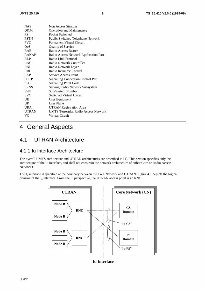
The Iu interface is specified at the boundary between the Core Network and UTRAN. Figure 4.1 depicts the logicaldivision of the Iu interface. From the Iu perspective, the UTRAN access point is an RNC.
Core Network (CN)UTRAN
RNCCS
Domain
PSDomain
Node B
Node B
Node B
Node B
RNC
Iu Interface
“Iu-PS”
“Iu-CS”
3GPP
TS 25.410 V2.0.0 (1999-09)10UMTS 25.410
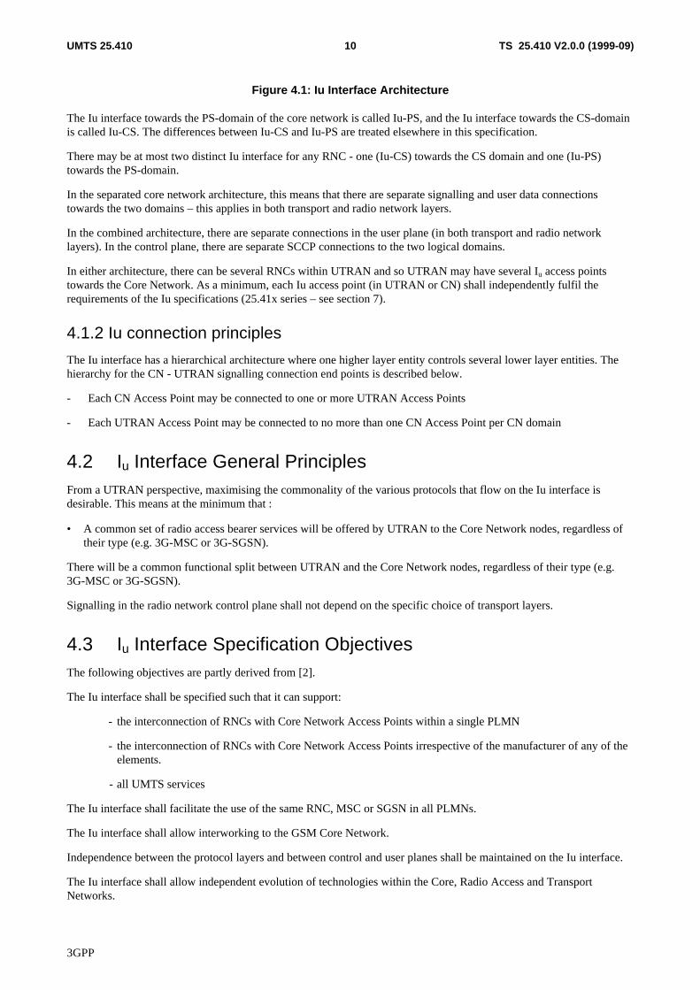
Figure 4.1: Iu Interface Architecture
The Iu interface towards the PS-domain of the core network is called Iu-PS, and the Iu interface towards the CS-domainis called Iu-CS. The differences between Iu-CS and Iu-PS are treated elsewhere in this specification.
There may be at most two distinct Iu interface for any RNC - one (Iu-CS) towards the CS domain and one (Iu-PS)towards the PS-domain.
In the separated core network architecture, this means that there are separate signalling and user data connectionstowards the two domains – this applies in both transport and radio network layers.
In the combined architecture, there are separate connections in the user plane (in both transport and radio networklayers). In the control plane, there are separate SCCP connections to the two logical domains.
In either architecture, there can be several RNCs within UTRAN and so UTRAN may have several Iu access pointstowards the Core Network. As a minimum, each Iu access point (in UTRAN or CN) shall independently fulfil therequirements of the Iu specifications (25.41x series – see section 7).
4.1.2 Iu connection principles
The Iu interface has a hierarchical architecture where one higher layer entity controls several lower layer entities. Thehierarchy for the CN - UTRAN signalling connection end points is described below.
- Each CN Access Point may be connected to one or more UTRAN Access Points
- Each UTRAN Access Point may be connected to no more than one CN Access Point per CN domain
4.2 Iu Interface General PrinciplesFrom a UTRAN perspective, maximising the commonality of the various protocols that flow on the Iu interface isdesirable. This means at the minimum that :
• A common set of radio access bearer services will be offered by UTRAN to the Core Network nodes, regardless oftheir type (e.g. 3G-MSC or 3G-SGSN).
There will be a common functional split between UTRAN and the Core Network nodes, regardless of their type (e.g.3G-MSC or 3G-SGSN).
Signalling in the radio network control plane shall not depend on the specific choice of transport layers.
4.3 Iu Interface Specification ObjectivesThe following objectives are partly derived from [2].
The Iu interface shall be specified such that it can support:
- the interconnection of RNCs with Core Network Access Points within a single PLMN
- the interconnection of RNCs with Core Network Access Points irrespective of the manufacturer of any of theelements.
- all UMTS services
The Iu interface shall facilitate the use of the same RNC, MSC or SGSN in all PLMNs.
The Iu interface shall allow interworking to the GSM Core Network.
Independence between the protocol layers and between control and user planes shall be maintained on the Iu interface.
The Iu interface shall allow independent evolution of technologies within the Core, Radio Access and TransportNetworks.
3GPP
TS 25.410 V2.0.0 (1999-09)11UMTS 25.410
The Iu interface shall allow separate evolution of O&M facilities.
The Iu interface shall be standardised as an open and multi-vendor interface.
The Iu interface specifications shall facilitate the migration of some services from the CS-domain to the PS-domain. Inparticular, the RANAP protocol shall be common to both domains, and the Iu user plane protocol(s) shall beindependent of the core network domain, except where a specific feature is only required for one domain.
4.4 Iu Interface CapabilitiesThe following capabilites are derived from the requirements described in [2].
The Iu interface supports:
- procedures to establish, maintain and release Radio Access Bearers
- procedures to perform intra-system handover, inter-system handover and SRNS relocation
- a set of general procedures, not related to a specific UE
- the separation of each UE on the protocol level for user specific signalling management
- the transfer of NAS signalling messages between UE and CN
- location services by transferring requests from the CN to UTRAN, and location information from UTRAN toCN. The location information may comprise a geographical area identifier or global co-ordinates with uncertaintyparameters
- simultaneous access to multiple CN domains for a single UE
- mechanisms for resource reservation for packet data streams
4.5 Iu Interface Characteristics
4.5.1 Use of Transport Network User Plane as Signalling Bearer
4.5.1.1 Use of SCCP
4.5.1.1.1 General
The SCCP is used to support signalling messages between the CNs and the RNC. One user function of the SCCP, calledRadio Access Network Application Part (RANAP), is defined. The RANAP uses one signalling connection per activeUE and CN for the transfer of layer 3 messages.
Both connectionless and connection-oriented procedures are used to support the RANAP. TS 25.413 explains whetherconnection oriented or connectionless services should be used for each layer 3 procedure.
RANAP may use SSN, SPC and/or GT and any combination of them as addressing schemes for the SCCP. Which of theavailable addressing scheme to use for the SCCP is an operator matter.
Which of the possible GT formats to be used is FFS. One option is to use the same format as for the MAP specification,i.e. GT format 4.
The following sections describe the use of SCCP connections for RANAP transactions. Section 4.5.1.2 describes theconnection establishment procedures. Section 4.5.1.3 describes the connection release procedures. Section 4.5.1.4describes abnormal conditions.
3GPP
TS 25.410 V2.0.0 (1999-09)12UMTS 25.410
4.5.1.1.2 SCCP connection establishment
A new SCCP connection is established when information related to the communication between a UE and the networkhas to be exchanged between RNC and CN, and no SCCP connection exists between the CN and the RNC involved, forthe concerned UE.
Various SCCP connection establishment cases have to be distinguished:
i) RNC Initiated SCCP Signalling Connection
ii) CN Initiated SCCP Signalling Connection
The above cases are the only cases currently identified for SCCP connection establishment. Others may emerge in thefuture.
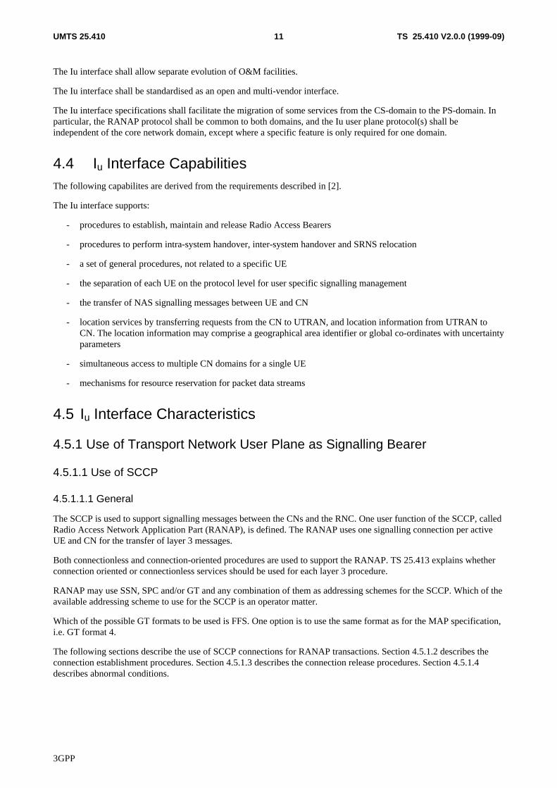
4.5.1.1.2.1 Establishment procedure in case i
The SCCP signalling connection establishment is initiated, by the RNC, at the reception of the first layer 3 non accessstratum message from the UE.
Initiation
The RNC sends SCCP connection request message to the Core Network. A RANAP message is included in the user datafield of the SCCP connection request message.
Termination
- successful outcome
• The SCCP connection confirm message, which may optionally contain a connection oriented RANAP message inthe user data field, is returned to the RNC.
- unsuccessful outcome
• If the SCCP signalling connection establishment fails, an SCCP connection refusal message will be sent back to theRNC. This message may contain a transparent message to be sent to the UE.
For more information on how the RANAP procedure Initial UE message is handled, please see the elementary procedureInitial UE message in TS 25.413 [6].
RNC CN
CR {SSN=RANAP, a1=x, RANAP message}------------------------------------------->
CC {a1=y,a2=x, RANAP message or no user data}<------------------------------------------
orCREF{a2=x, RANAP message or no user data}
<------------------------------------------
a1 = source local reference,a2 = destination local reference,
x = SCCP connection reference at the RNC,y = SCCP connection reference at the CN.
Figure 4.2: Setting-up of RNC Initiated SCCP Signalling Connection
3GPP
TS 25.410 V2.0.0 (1999-09)13UMTS 25.410
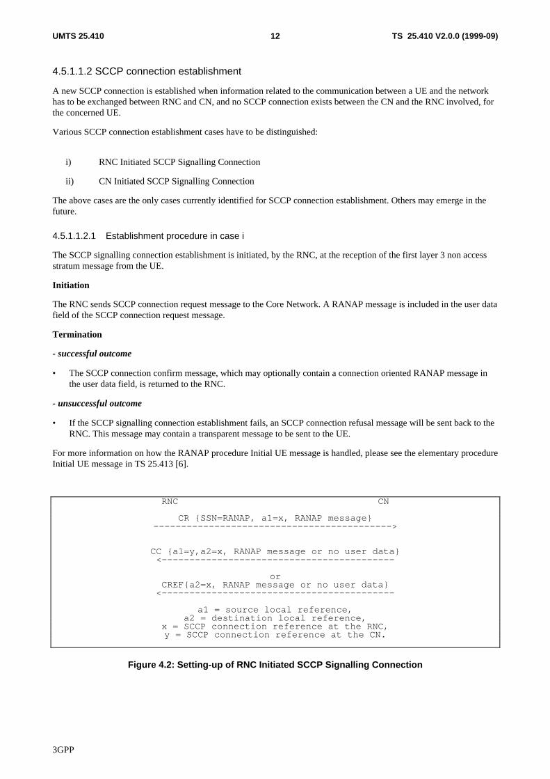
4.5.1.1.2.2 Establishment procedure in case ii
The SCCP signalling connection establishment is initiated, by the Core Network, in connection with performing aRelocation.
Initiation
The Core Network initiates the connection establishment by sending an SCCP connection request message to the RNC.Optionally, a RANAP message may be included in the user data field of the SCCP connection request message.
Termination
- successful outcome
• The SCCP connection confirm message, which may optionally contain a connection oriented RANAP message inthe user data field, is returned to the Core Network.
- unsuccessful outcome
• If the SCCP signalling connection establishment fails, an SCCP connection refusal message will be sent back to theCore Network. This message may contain a RANAP message in the user data field.
RNC CN
CR {SSN=RANAP, a1=y,RANAP message or no user data}<-----------------------------------------
CC {a1=x, a2=y, RANAP message or no user data}------------------------------------------>
orCREF{a2=y, RANAP message or no user data}
------------------------------------------>
a1 = source local reference,a2 = destination local reference,
x = SCCP connection reference at the RNC,y = SCCP connection reference at the CN.
Figure 4.3: Setting-up of CN Initiated SCCP Signalling Connection
4.5.1.1.3 SCCP connection release
This procedure is always initiated at the Core Network side.
An SCCP connection is released when the CN realises that a given signalling connection is no longer required.
The CN sends a SCCP Released message.
4.5.1.1.4 General SCCP Abnormal Conditions
If a user-out-of-service information or signalling-point-inaccessible information is received by the RANAP, no newattempt to establish SCCP connections towards the affected point code will be started until the corresponding user-in-service information or signalling-point-accessible information is received.
When a user-out-of-service information or signalling-point-inaccessible is received by the RNC, an optional timer maybe started. When the timer expires, all the SCCP connections towards the affected point code will be released. When theuser-in-service or signalling-point-accessible is received, the timer is stopped.
If for any reason an SCCP connection is released, the optional timer expires or a connection refusal is received whileany of the RANAP procedures are being performed or while a dedicated resource is still allocated, the following actionsare taken:
3GPP
TS 25.410 V2.0.0 (1999-09)14UMTS 25.410
At RNC:
• Any RNC procedure relating to that connection is abandoned.
• The UTRAN resources allocated to the connection are released.
At Core Network:
• The resources associated with the SCCP connection are cleared as soon as possible.
4.5.2 Use of Transport Network User Plane as User Data Bearer
4.5.2.1 Use of AAL2
AAL2 is used as the user data bearer towards the CS domain.
Q.2630.1 is used as the protocol for dynamically setup AAL-2 connections over Iu towards the CS domain.
4.5.2.2 Use of GTP-U
GTP-U is used as the user data bearer towards the PS domain.
RANAP Signalling is used to establish, modify and release the GTP-U tunnels towards the PS domain.
5 Functions of the Iu Interface Protocols & Functional Split
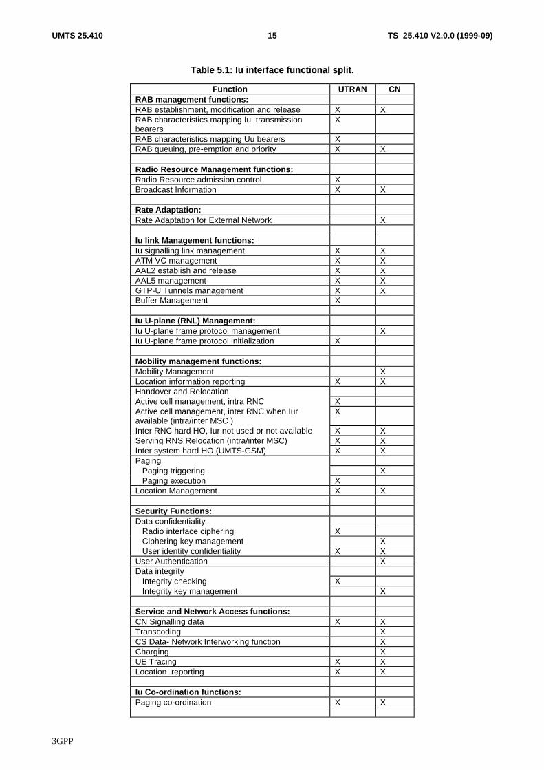
5.1 GeneralThis section defines the functional split between the core network and the UMTS radio access network. In addition, thepossible interaction between the functions is defined. The functional split is shown in table 5.1.
3GPP
TS 25.410 V2.0.0 (1999-09)15UMTS 25.410
Table 5.1: Iu interface functional split.
Function UTRAN CNRAB management functions:RAB establishment, modification and release X XRAB characteristics mapping Iu transmissionbearers
X
RAB characteristics mapping Uu bearers XRAB queuing, pre-emption and priority X X
Radio Resource Management functions:Radio Resource admission control XBroadcast Information X X
Rate Adaptation:Rate Adaptation for External Network X
Iu link Management functions:Iu signalling link management X XATM VC management X XAAL2 establish and release X XAAL5 management X XGTP-U Tunnels management X XBuffer Management X
Iu U-plane (RNL) Management:Iu U-plane frame protocol management XIu U-plane frame protocol initialization X
Mobility management functions:Mobility Management XLocation information reporting X XHandover and RelocationActive cell management, intra RNC XActive cell management, inter RNC when Iuravailable (intra/inter MSC )
X
Inter RNC hard HO, Iur not used or not available X XServing RNS Relocation (intra/inter MSC) X XInter system hard HO (UMTS-GSM) X XPaging Paging triggering X Paging execution XLocation Management X X
Security Functions:Data confidentiality Radio interface ciphering X Ciphering key management X User identity confidentiality X XUser Authentication XData integrity Integrity checking X Integrity key management X
Service and Network Access functions:CN Signalling data X XTranscoding XCS Data- Network Interworking function XCharging XUE Tracing X XLocation reporting X X
Iu Co-ordination functions:Paging co-ordination X X
3GPP
TS 25.410 V2.0.0 (1999-09)16UMTS 25.410
5.2 RAB management Functions
5.2.1 RAB establishment, modification and release function
The RAB, Radio Access Bearer, is defined to be set-up between UE and CN. Depending on subscription, service,requested QoS etc. different types of RABs will be used. It is the CN that controls towards the UTRAN theestablishment , modification or release of a RAB.
The RAB identity is allocated by CN and is locally significant over one Iu signalling instance.
RAB establishment, modification and release is a CN initiated function.
RAB establishment, modification and release is a UTRAN executed function.
RAB release request is a UTRAN initiated function, triggered when UTRAN fails to keep the RAB established with theUE.
5.2.2 RAB characteristics mapping to Uu bearers function
The RAB characteristics mapping function is used to map the radio access bearers to the Uu bearers. The mapping isperformed during the establishment of the RAB. UTRAN shall perform the mapping between the bearers.
RAB mapping to Uu transmission bearers is a UTRAN function.
5.2.3 RAB characteristics mapping to Iu transport bearers
The RAB characteristics mapping function is used to map the radio access bearers to the Iu interface transport bearers.The mapping is performed during the establishment of the RAB.
UTRAN shall perform this mapping between the bearers if AAL2 is used, since it is the UTRAN that establish theAAL2 connections.
In case of RAB towards the IP domain, UTRAN shall perform the mapping between the radio access bearers and the IPlayer.
RAB characteristics mapping to Iu transport bearers is a UTRAN function.
5.2.4 RAB queuing, pre-emption and priority function
The priority level of a RAB is determined by the CN based on e.g. subscription information , QoS information etc..Accordingly, the CN shall request RAB establishment or modification with an indication of the priority level and thepre-emption capability of that RAB and the queuing vulnerability. Queuing and resource pre-emption shall be performedby UTRAN accordingly.
RAB queuing, pre-emption and priority handling is a UTRAN controlled function.
RAB queuing, pre-emption and priority setting is a CN function.
5.3 Radio Resource Management over Iu
5.3.1 Radio resource admission control
This function is used at radio access bearer establishment and it is divided in two parts:
a) Subscription based admission control
3GPP
TS 25.410 V2.0.0 (1999-09)17UMTS 25.410
When CN receives a request to establish or modify a radio access bearer, the CN verifies if the subscriber is allowed touse a radio access bearer with the requested parameters. Based on the verification the CN will accept or reject therequest. This part is called "Subscription based admission control" and it is handled by the CN.
b) Radio resource admission control
When UTRAN receives a request to establish or modify a radio access bearer from the CN, the current radio resourcesituation is analysed and the admission control either accepts or rejects the request. This part is called "Radio resourceadmission control" and it handled by the UTRAN. If the request is queued, this part is handled by the RAB queuing,pre-emption and priority function.
Part b) is only performed if CN accept the request to establish a radio access bearer
5.3.2 Broadcast information management
This function consists in the broadcast from network toward UE of some information in the coverage area of the wholenetwork or different parts of the network.
There are two kinds of Broadcast information management. UTRAN broadcast information and CN broadcastinformation management. All UTRAN broadcast information management shall be be handled locally within UTRAN.All CN related broadcast information is controlled by CN. UTRAN executes the broadcast of CN information.
5.4 Rate adaptation for external networksThe rate adaptation function is used to adapt the radio interface data transmission rates with the terrestrial linktransmission rates and with the external networks (such as PSTN and ISDN) rates.
The Rate adaptation for external network is a CN function.
5.5 Iu link Management functions
5.5.1 Iu Signalling Link Management function
The Iu signalling link management function provides a reliable transfer of the radio network signalling between UTRANand CN. Both CN and UTRAN manage the function.
This function is in particular responsible for Iu signalling connection establishment, which can be established either bythe CN or the RNC and for Iu signalling connection release, which is controlled by CN possibly upon UTRAN request.
5.5.2 ATM Virtual Connection Management function
This function refers to handling of ATM Virtual Connections (VCs) between CN and UTRAN.
This function shall be used to establish, maintain and release the ATM VCs. For permanent VCs, it is regarded to be anO&M function.
This function also includes the selection of a Virtual Circuit to be used for a particular RAB. The selection of ATM VCupon an Iu radio access bearer service request, shall be done by UTRAN. The selected VC shall fulfil the requirementsof the request. AAL5 adaptation layer will be used over a virtual circuit for signalling. AAL5 and AAL2 adaptationlayers will be used over virtual connections for used data. The VC may consist of several sublinks: such as SCCPconnections, AAL2 connections or IP flows.
5.5.3 AAL2 connection establish and release function
This function is used to establish and release the AAL type 2 connections between CN and UTRAN upon an Iu radioaccess bearer service request. Both UTRAN and CN are taking part in the establishment of AAL2 connection. UTRANshall initiate the establishment. UTRAN shall perform the release of the AAL2 connection upon request of the CN. Theuse of AAL2 for Iu transmission bearers depends on type of CN.
3GPP
TS 25.410 V2.0.0 (1999-09)18UMTS 25.410
5.5.4 AAL5 management function
AAL5 connections between CN and UTRAN shall be pre-configured at system initialisation. Basic configuration isPVCs. For user data, SVC is possible.
The AAL5 management is a function handled by both the CN and the UTRAN.
5.5.5 GTP-U tunnels management function
This function is used to establish and release GTP-U tunnels between CN and UTRAN upon a radio access bearerservice request. This involves assigning a tunnel identifier for each direction and the creation of a context containing thetunnel information. The use of GTP-U for Iu transport bearers depends on type of CN.
5.5.6 Buffer Management
Congestion control shall be performed over the Iu user plane toward the PS domain using buffer management and noflow control.
This function includes buffers to store received packet data units that at reception can not be processed due to e.g.congestion. In UTRAN, there must be a buffer management function handling received packets from the peer CN node.
Congestion control shall be performed over Iu user plane towards to PS domain using buffer management and no flowcontrol.
The used mechanism is not in the scope of this document and not relevant to be standardised.
Buffer management is a UTRAN function.
5.6 Iu U-plane (RNL)Management Functions
5.6.1 Iu U-plane frame protocol mode selection function
The Iu UP in the Radio Network Layer provides modes of operation that can be activated on RAB basis. For a givenRAB, the Iu UP operates either in a Transparent or in Support mode. Iu U-plane frame protocol mode is selected by theCN..
This function is a CN function.
5.6.2 Iu U-plane frame protocol initialisation
Iu U-plane frame protocol is initialised by the UTRAN.
5.7 Mobility Management Functions
5.7.1 Mobility Management
The mobility management is used to maintain the information in the CN about the location of the terminal. The functionis needed for support of UE roaming and for support of UE terminating traffic. All Mobility Management signallingbetween UE and CN are transferred transparently through UTRAN, except paging.
For Mobility Management purposes, the location information shall be at Location and Routing Area level.
5.7.2 Location information update function
Functionality within the CN, such as Charging, needs information about the present location of active UE, i.e. UE withestablished signalling connection. The Location information update function is used to transfer this information from theUTRAN to the CN. It is the UTRAN responsibility to send this information initially at the signalling connection
3GPP
TS 25.410 V2.0.0 (1999-09)19UMTS 25.410
establishment for an UE and at any change of the UE location as long as the signalling connection exists. For MobilityManagement purposes, the location information shall be at Location and Routing Area level.
5.7.3 Handover and Relocation functions
5.7.3.1 Active Cell Management, intra RNC
This functionality includes procedures for adding and removing cells controlled by one RNC to and from the active set.The handovers may be hard or soft. This functionality is handled by UTRAN and it does not involve the CN.
5.7.3.2 Active Cell Management, inter RNC, when Iur is available
This functionality includes procedures for adding and removing cells controlled by an other RNC to and from the activeset. This is possible only when Iur interface is available between the RNCs in question. As long as the Iur is available,the RNCs may be controlled by different MSCs, i.e. both intra and inter MSC cases are applicable. The handovers maybe hard or soft. This functionality is handled by UTRAN and it does not involve the CN.
5.7.3.3 Inter RNC hard HO function, Iur not used or not available
This functionality includes procedures for handover from one RNC to other RNC when Iur interface is not used or is notavailable, i.e. soft handover is not possible. The connection is switched in the CN, so both UTRAN and CN areinvolved. Both intra and inter CN entity cases are applicable.
5.7.3.4 Serving RNS Relocation function
This functionality allows moving the Serving RNS functionality from one RNC to an other RNC, e.g. closer to where theUE has moved during the communication. The Serving RNS Relocation procedure may be applied when active cellmanagement functionality has created a suitable situation for it. Both UTRAN and CN are involved.
5.7.3.5 Inter system Handover (e.g. GSM-UMTS) function
Inter system handover is performed when a mobile hands over between cells belonging to different systems such asGSM and UMTS. This may imply also a change of radio access type. For intersystem handover between UMTS andGSM, the GSM procedures are used with the GSM network. Both UTRAN and CN are involved.
Note: The GSM BSSMAP procedures are outside the scope of this specification.
5.7.4 Paging
5.7.4.1 Paging triggering function
The Core Network shall, when considered necessary, trigger the paging in the UTRAN system.
5.7.4.2 Paging execution function
The paging function shall be executed by UTRAN.
5.7.5 Location Management
The location management is used to maintain the information about the location of the terminal.
The location management of an idle terminal is handled within the CN at the level of Location/Routing Area. TheUTRAN controls the location management of active terminals, i.e. the UTRAN knows which cells/URA are used by theactive terminal.
3GPP
TS 25.410 V2.0.0 (1999-09)20UMTS 25.410
5.8 Security Functions
5.8.1 Data Confidentiality
5.8.1.1 Radio interface ciphering function
The radio interface shall be ciphered upon request of the Core Network. Both Signalling and user data may be subject tociphering. The ciphering shall be done within UTRAN.
5.8.1.2 Ciphering key management function
The ciphering key and the permitted algorithm shall be supplied by the CN. UTRAN selects the used algorithm.
5.8.1.3 User identity confidentiality function
The UMTS user identity confidentiality is obtained by using a temporary UE identity rather than the permanent UEidentity (i.e. IMSI) over the radio path.
The CN allocates to each visiting UE a temporary identity. This identity is used by the UE when establishing a newconnection between the CN and the UE. It is used by the CN when requesting a page.
In addition, UTRAN allocates to each UE with established RRC connection a temporary identity (Radio NetworkTemporary Identity, RNTI). This identity is used to identify an UE when on common radio channels.
5.8.2 Terminal identity check function
The terminal identity check be provided by the CN. The Iu interface is required to transport necessary request andresponse messages between the CN and UE.
5.8.3 User Authentication function
The user authentication shall be provided by the CN. The authentication functions are transparent for the Iu Interface,and therefore outside the scope of Iu Interface documents.
5.8.4 Data integrity
5.8.4.1 Integrity checking
The purpose of the integrity check is to make sure that the signalling continues between the same elements as byauthentication. The integrity check shall be done within the UTRAN.
5.8.4.2 Integrity key management
The integrity key and the permitted algorithm shall be supplied by the CN. UTRAN selects the used algorithm.
5.9 Service and Network Access Functions
5.9.1 Core Network signalling data transfer function
The PS respective the CS CN signalling data such as Call Control (CC), Session Management (SM), MobilityManagement (MM), Short Message Services Point to Point and Supplementary Services (SS) shall be transparentlyconveyed over the Iu interface. The signalling information shall be conveyed transparently over the same Iu interfacechannel that is used for the UTRAN-CN signalling.
3GPP
TS 25.410 V2.0.0 (1999-09)21UMTS 25.410
5.9.2 Transcoding function
The transcoding functionality is needed for changing the coding of a voice call from one coding scheme to another. Thetranscoder placement is within the CN. The transcoding functionality is therefore placed in the CN only. Over the Iuinterface, transcoded speech shall be treated a data service with specific Quality of Service requirement.
5.9.3 CS data – Network Interworking function
The network interworking function is used to modify the Iu UP frames to match the requirements of the external networksuch as PSTN or ISDN. The network interworking function may consist of rate adaptation and/or error correcting linkprotocol such as GSM RLP.
The network interworking function between the CN and external networks (such as PSTN and ISDN) shall be handledby CN.
5.9.4 Charging
Charging shall be handled by CN. The charging may be based on the used radio resources, received Quality of Serviceor on the amount of transmitted data.
5.9.5 UE Tracing
This feature allows tracing of various events related to the UE and its activities. This is an O&M functionality.
5.9.6 Location reporting function
The positioning function performs the determination of the geographical position for an UE. The location reportingfunction transfer the positioning information between the UTRAN and the CN according to CN commands. Thisfunction involves UTRAN and CN.
5.10 Co-ordination Functions
5.10.1 Paging Co-ordination function
The two CN domain architecture implies need for a page co-ordination, i.e. handling of page triggered by one CN nodewhen UE has a signalling connection to the other CN node. The paging co-ordination is performed by UTRAN and/oroptionally by CN. The Common ID is used for UTRAN paging co-ordination. The CN provides the UTRAN with theCommon ID.
The paging co-ordination is a UTRAN function. Optionally the paging co-ordination may be performed in the CN.
6 Iu Interface Protocol Structure
6.1 GeneralThe Radio Network signalling over Iu consists of the Radio Access Network Application Part (RANAP). The RANAPconsists of mechanisms to handle all procedures between the CN and UTRAN. It is also capable of conveying messagestransparently between the CN and the UE without interpretation or processing by the UTRAN.
Over the Iu interface the RANAP protocol is, e.g. used for:
• Facilitate a set of general UTRAN procedures from the Core Network such as paging -notification as defined bythe notification SAP in [3].
3GPP
TS 25.410 V2.0.0 (1999-09)22UMTS 25.410
• Separate each User Equipment (UE) on the protocol level for mobile specific signalling management as definedby the dedicated SAP in [3].
• Transfer of transparent non-access signalling as defined in the dedicated SAP in [3].
• Request of various types of UTRAN Radio Access Bearers through the dedicated SAP in [3].
• Perform the SRNS Relocation function.
The Radio Access Bearers are provided by the Access Stratum
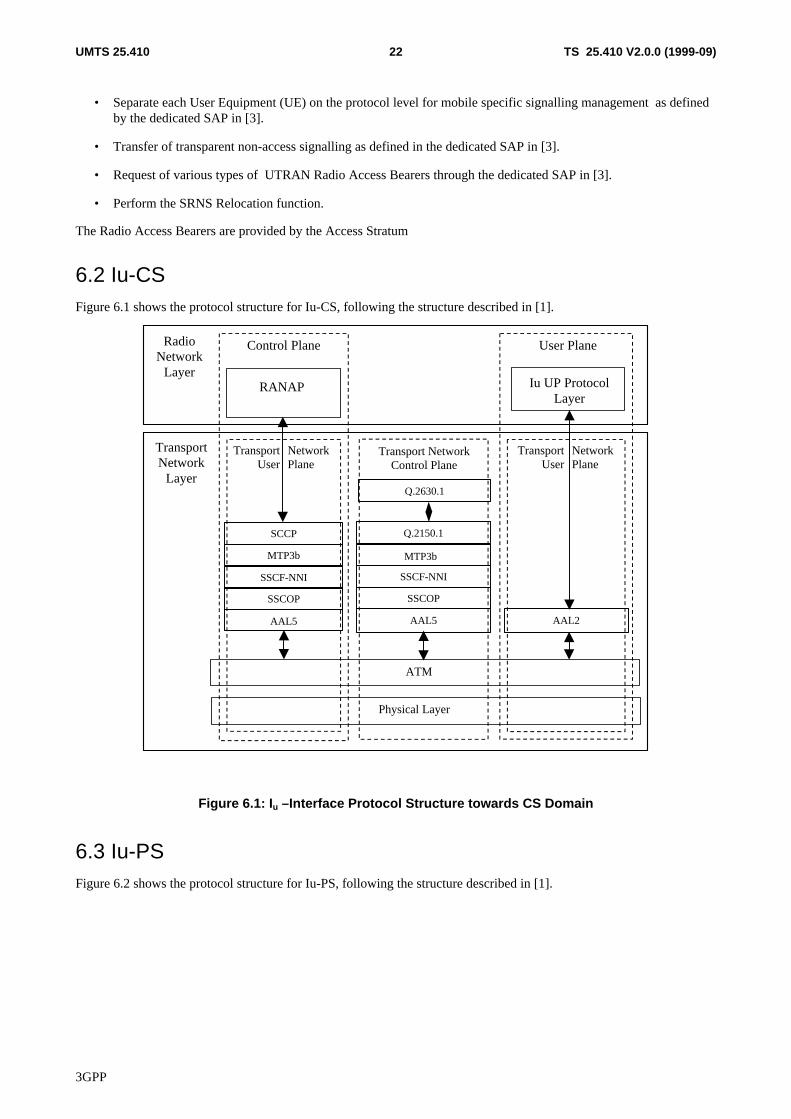
6.2 Iu-CSFigure 6.1 shows the protocol structure for Iu-CS, following the structure described in [1].
Q.2150.1
Q.2630.1
RANAP Iu UP ProtocolLayer
TransportNetwork
Layer
Physical Layer
TransportUser
NetworkPlane
Control Plane User Plane
TransportUser
NetworkPlane
Transport NetworkControl Plane
RadioNetwork
Layer
ATM
SSCOP
AAL5
SSCOP
SSCF-NNI
AAL2AAL5
MTP3bMTP3b
SCCP
SSCF-NNI
Figure 6.1: Iu –Interface Protocol Structure towards CS Domain
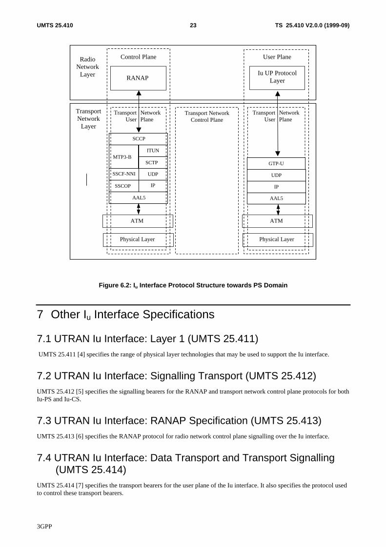
6.3 Iu-PSFigure 6.2 shows the protocol structure for Iu-PS, following the structure described in [1].
3GPP
TS 25.410 V2.0.0 (1999-09)23UMTS 25.410
SSCF-NNI
SSCOP
AAL5
IP
SCTP
SCCP
SSCF-NNI UDP
MTP3-BITUN
RANAPIu UP Protocol
Layer
TransportNetwork
Layer
Physical Layer
TransportUser
NetworkPlane
Control Plane User Plane
TransportUser
NetworkPlane
Transport NetworkControl Plane
RadioNetwork
Layer
ATM
AAL5
IP
UDP
GTP-U
Physical Layer
ATM
Figure 6.2: Iu Interface Protocol Structure towards PS Domain
7 Other Iu Interface Specifications
7.1 UTRAN Iu Interface: Layer 1 (UMTS 25.411) UMTS 25.411 [4] specifies the range of physical layer technologies that may be used to support the Iu interface.
7.2 UTRAN Iu Interface: Signalling Transport (UMTS 25.412)UMTS 25.412 [5] specifies the signalling bearers for the RANAP and transport network control plane protocols for bothIu-PS and Iu-CS.
7.3 UTRAN Iu Interface: RANAP Specification (UMTS 25.413)UMTS 25.413 [6] specifies the RANAP protocol for radio network control plane signalling over the Iu interface.
7.4 UTRAN Iu Interface: Data Transport and Transport Signalling(UMTS 25.414)
UMTS 25.414 [7] specifies the transport bearers for the user plane of the Iu interface. It also specifies the protocol usedto control these transport bearers.
3GPP
TS 25.410 V2.0.0 (1999-09)24UMTS 25.410
7.5 UTRAN Iu Interface: CN-UTRAN User Plane Protocol (UMTS25.415)
UMTS 25.415 [8] specifies the user plane frame handling protocol for the Iu interface.
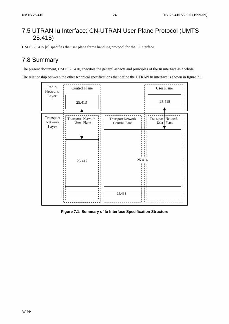
7.8 SummaryThe present document, UMTS 25.410, specifies the general aspects and principles of the Iu interface as a whole.
The relationship between the other technical specifications that define the UTRAN Iu interface is shown in figure 7.1.
25.413 25.415
TransportNetwork
Layer
25.411
TransportUser
NetworkPlane
Control Plane User Plane
TransportUser
NetworkPlane
Transport NetworkControl Plane
RadioNetwork
Layer
25.412 25.414
Figure 7.1: Summary of Iu Interface Specification Structure
3GPP
TS 25.410 V2.0.0 (1999-09)25UMTS 25.410
8 History
Document history
v 0.0.1 1999-02 Initial Specification Structure
V0.0.2 1999-02 Text from merged document included.
V0.0.3 1999-03 Updated with decision from WG3 #2 (inclusion of IP domain congestion control)
V0.1.0 1999-04 Approved by WG3
v.0.1.1 1999-05 Updated with decisions from WG3 #3 – mostly from Tdoc 344. References andCh7 updated according to document renumbering.
v.0.1.2 1999-06 Further changes after SWG review, and text from Iu SWG @ WG3#4 added. –This version was never treated in a WG3 meeting.
v.0.2.1 1999-06 Approved at WG3#4, and showing changes agreed at that meeting – sentence onestablishment of GTP-U tunnels, and commonality of U-plane protocols.
v.0.3.1 1999-08 Approved at WG3#5, and showing changes agreed at that meeting – figuresupdated to show single UP protocol, and with SCCP usage text (modified fromtdoc 725)
v.1.0.0 1999-08 Approved at WG3#6, and showing changes agreed at that meeting. Includingcorrections/clarifications to SCCP section, new text for architecture, objectives andcharacteristics sections.
v.1.0.1 1999-09 Includes (unmarked) changes from b74 (Editor’s Proposal). Also marked changesarising from discussions on b74 and modified text from b49.
v.1.0.2 1999-09 Agreed by Iu SWG – includes as unmarked changes from 1.0.1 new abbreviations,two corrected spellings and updated capability regarding location services.
v.2.0.0 1999-09 Approved by RAN3, some modifications to relax the restrictions on CNarchitecture. Also, corrections to SCTP stack (inclusion of ITUN).
Editor for 3GPP RAN 25.410 is:
Richard TownendBT
Tel.: +44 1473 605 429Fax : +44 1473 623 683Email : [email protected]
This document is written in Microsoft Word version 7/97.


![443 ] RESULT OF MECHANICAL EN - FAMT](https://img.dokumen.tips/doc/110x75/63150662aca2b42b580dba68/443-result-of-mechanical-en-famt.jpg)