Embed Size (px)
Citation preview

Architectural Desigfor
Earthquake
f 4
A guide to the design ofnon-structural elements
=-....-I.../.....ill-*-I..I---I--..:----.-.-I....I.-I....- -ENG 249-(EQC 1989/)
Architectural Design for Earthquake - A guide to the design ofnon-structural elementsW Massey (KRTA Ltd), L Megget (School Of Engineering,University Of Auckland)

Cover photo:Union House
Quay Street Auckland
Architects: Warren & MahoneyStructural Engineers: Holmes Consulting Group
Architectural Designfor
Earthquake
A guide to the design ofnon-structural elements
A project sponsored by theNew Zealand Earthquake andWar Damage CommissionPublished by the New ZealandNational Society forEarthquake Engineering
N_ LimitedWarwick MasseyArchitectural Managerassisted byLes MeggetSenior Lecturer, School of EngineeringUniversity of Auckland
NEW ZEALAND NATIONAL SOCIETY
FOR EARTHQUAKE ENuINEERINGP.O. BOX 17268 KARORI
WELLINGTON. NEW ZEALAND
Preface
This book is intended to promote adequate performance of non-structural elements in earthquake - both to reduce damage andto avoid adverse structural effects.
Recognition of the need for a New Zealand guide to the architec-turaldesign ofnon-structuralelements arose out ofmeetings, dis-cussions and enquiry conducted by a NZ National Society forEarthquake Engineering Study Group. Most engineers, somearchitects and a few other specialist designers understand theprinciples of designing for the protection of non-structural ele-ments, but many others, who are directly concerned with detail-ing, specifying and constructing buildings, do not appreciate theeffects of earthquake shaking.
This book provides an overview and most topics are at least sum-marised and references given to sources of further information.In no way does it replace involvement by professional engineersand architects in appropriate aspects of design. On the contraryit is intended to heighten awareness of the need for engineeringinvolvement in the design of non-structural elements.
As one architect who has recognised the need for, but difficultyof producing, cost effective details that meet New Zealand earth-quake code requirements I hope the information provided willhelp architects and engineers to work together to produce de-signs which are functional, aesthetic and achieve a high standardof earthquake performance.
Warwick MasseyMay 1992

1
1
I
1
1
- Acknowledgements
The genesis of this handbook was in meetings of a NZNSEE
I Study Group in 1986-1987. Recognition is due to the members ofthat group, which included: Adrian Bennett, John Christianson,Laurie and David Hayes, Henry James, Andrew King, ErnestLapish, Les Megget, Ken Muholland, Geoff Sidwell, MauriceTebbs and the writer.
I am grateful to those who have read and commented on parts ofthe text, including Chris Arnold, David Hopkins, Alan Perry andAndrew Charleson; also to Mark Smith and Peter Weston for
their background research. In particular my thanks to SilvaBassett for her desk top publishing skills.
Finally I acknowledge the help of Les Megget; his major contri-bution to the text and his essential engineering advice.
1WEM
1
1
1
1
1
1
1
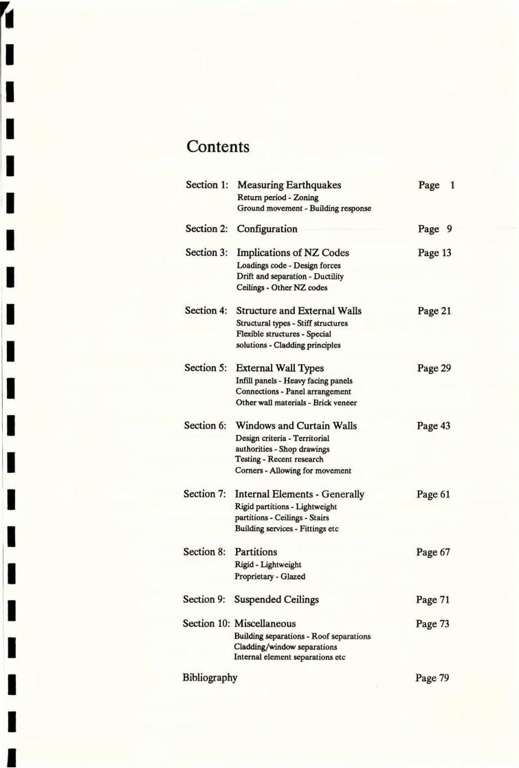
Contents
Section 1: Measuring Earthquakes Page 1Return period - Zoning
Ground movement - Building response
Section 2: Configuration -- Page 9
Section 3: Implications of NZ CodesLoadings code - Design forcesDrift and separation - Ductility
Ceilings - Other NZ codes
Page 13
Section 4: Structure and External Walls
Structural types - Stiff structuresFlexible structures - Specialsolutions - Cladding principles
Page 21
Section 5: External Wall TypesInfill panels - Heavy facing panelsConnections - Panel arrangementOther wall materials - Brick veneer
Page 29
Section 6: Windows and Curtain Walls
Design criteria - Territorialauthorities - Shop drawings
Testing - Recent research
Corners - Allowing for movement
Page 43
Section 7: Internal Elements - GenerallyRigid partitions - Lightweightpartitions - Ceilings - Stairs
Building services - Fittings etc
Page 61
Section 8: Partitions Page 67Rigid - Lightweight
Proprietary - Glazed
Section 9: Suspended Ceilings Page 71
Section 10: Miscellaneous
Building separations - Roof separationsCladding/window separationsInternal element separations etc
Page 73
Bibliography Page 79

This handbook is about design of non-structural elements - that is, those
parts of buildings which do not or are not intended to resist loads appliedto the structure of the building. This may include:
e Cladding panels of various materials
e Windows and exterior walling systems
e Internal walls and partitions
i Suspended ceilingsStairways
e Equipment itemse Building services
In this text only briefreference is made to the behaviour ofbuilding services
in earthquake.

1
1
1
1
1
1
1
1
1
1
1
1
1
1
1
1
1
1
1

Introduction
Design of non-structural elements is important because:
I Non-structural parts of a building have the potential tomodify earthquake response of the primary structure in anunplanned way. This can lead to severe structural damageor even collapse. (Figure 2.1)
• Damage to non-structural elements themselves mayprevent the building from functioning after an earthquake,or make it useless, even though the structure remainssound. (Figure 3.1)
i Failure of non-structural components may cause death orinjury from:- falling panels, masonry or glass- collapsed ceiling components
falling fittings and fixtures- debris blocking exitways, etc.
• Evidence from earthquakes around the world shows thatnon-structural damage typically represents the greatestmonetary loss in an earthquake. (Figure 1.1)
.
1l
1!It
Figure 1.1
Damage to partitions and ceilings in DDFWater Supply Secretariat, Mexico City.September 1985.
¥"m
A suivey of 355 high-rise buildings after the1971 San Fernando earthquake showedthat, in dollar value terms, 79% of thedamage was non-structural.(1)
1
1

New Zealand lies on the so-called ring of fire which encirclesthe Pacific and includes the Philippines, Japan, Alaska, the WestCoast of USA and South America. The boundary between theIndian-Australian and Pacific tectonic plates passes through thelength of the South Island and most of the North Island. Asdifferent parts of the earths crust at the plate boundaries aretrying to move in different directions there is an on-going cycle ofstress build up followed by rupture and accompanying energyrelease. It is this process, sometimes gradual and sometimessudden, that causes earthquakes.
•-u
1 Ch i#Af:
*f¢44*t**33 -EURK#IANPLK*F., 11 - .:....i:'f.: .*'.. 0. rg UrvbJurfil-
:....·s,e.·,Ae
MERICA artrf'-ri·.-f V···· ··,·...+,·t,·,...,...,...., <P PLATEL·r .: .
44 .0 .................... , '632*,A¢Ra:¥*2*3.e:9.0>
.. . I . -,I ./ 0, 1P CFC PLAT :4. .:.i·· da -
i i F IP I .- .*#ii¢k-·5:... 0,14,·.·... ' ' --'"' tis:**S SRE, i.:22 NDIA , ..T#X ·&&44·§·' ·' ' -
. AUSTRALIARIA AZC *.4 . f ,::: 9:€
LATerreatea 268.TE ,6; .>·.:.>:·:·:···6010/:ek; :b..
*fi:...: 3: 0:....,..' .4. .........................
....................... ......
C :8:3:5:3:ke 6...:>S:k'::M :....:0. D....
•.•:.,*'1.':.4:tf#*14*Nit·'.:'.f4**t***,M:;:*:*2¥i¢-*.ieic¢*I¥2fEk;*d#S#%*040'&:pri i0(}StE:3: 4% -·'/*:**M·4*>:,*: 444*20:b:.1:.· 11:049Ift:*4:3it',4*7:0:,i,:44:*•:v....·- Subduction Zone · Direction of plate molk,n
tri
lili
.. fli Y
.OW?Ii¥¥.ib *Io,;Xk'.
billillillillillill
Et{*I,¢;
Figure 1.2
The earth's crustis composed of at least 15 rigidvirtually undistortedslabs or plates of lithosphere, 7 of which occupy considerableareas of thc globe and are shown on this map. Boundaries of platesare of fourprincipat types: divergentorspreadingzones, whereplatesare separating and new plate material is being added; subductionzones, where plates converge and one plate is being consumed;collision zones, former subduction zones where continents rid-
ingon plates are colliding; and transform faults, where two plates aresimply gliding past one another, with no addition or destruction ofplate material.
Almost all the earthquake, volcanic, and mountain-building activitywhich marks the active zones of the earths crust closely followsthe boundaries ofplates and is related to movements between them.As may be seen from the diagram, New Zealand straddles one suchactive zone, astride the boundary between the Indian-Australianplate and Pacific plate.
\Reproduced with permission from Lands in Collision: DiscoveringNew Zealand's past geography, Graeme Stevens, Wellington, NZ:SU'C.]
2

MeasuringEarthquakes
Two terms are frequently confused when talking about earth-quakes. They are magnitude and intensity.
i The magnitude of an earthquakeisameasureofitssize andrelates to the amount of energy released, usually by rupturing ofthe fault.
e The intensity of an earthquake is measured at a particularsite and depends upon:
- magnitude of the earthquake,- depth of the earthquake source,- distance fromthe epicentre(thepoint onthe earths
surface directly above the source,- ground conditions at the observation site, and
between there and the source,
- duration of the shaking.
Magnitude is generally measured in terms of the Richter scale.Every time the Richter magnitude increases by one it representsa twenty-sevenfold increase in the size of the earthquake. Inother words, a Richter magnitude 7 earthquake releases 27 timesmore energy than a magnitude 6 earthquake.
Intensity is often quoted in terms of the Modified Mercalli scalewhich is graded MM1 to MM12. This scale is based on observedeffects and as such is subjective. For instance MM6 is describedas:
Felt by all; many frightened and run outdoors; someheavy furniture moved; a few instances of fallen plaster ordamaged chimneys; damage slight.
Figure 1.3The accelerogram provides a picture of theground shaking from which the magnitudeof the earthquake can be derived.
Reproduced with permission from Bruce A.Bok Earthquakes: A Primer [San Fran-cisco: W.H. Freeman and Company 1978].
s.wave- 30
20p. wave maximum wave
amplitude10
10
time 20
|T'mm""T"T1""7""I sec0 10 20 30 40 50 60 70

Return
Period
Figure 1.4 shows the epicentres of shallow earthquakes in NewZealand, of magnitude 6.5 and greater, since 1840. The greaterconcentration of earthquakes in some parts of the country isevident.
1014
1088
Figure 1.4Epicentres of shallow earthquakes of mag-nitude 63 and greater, since 1840.Reproduced with permission #om SmithWD., "Revised Estimates of EarthquakeHazard in New Zealand" Bull. NZNSEE,Vol 16 No. 4, December 1983, p.263
YEAR 7 and greater
6.5 to 6.9
From earthquakes feltinNew Zealand overtheperiod 1840-1987the return period for upper MM intensities has been estimated.(2) As examples:
• For the Wellington area, on average ground:
- MM VI intensity every 6 years- MM VII intensity every 21 years- MM VIII intensity every 67 years- MM IX intensity every 220 years
e In the Auckland area the predicted return periods aremuch longer:
- MM VI intensity every 48 years- MM VII intensity every 200 years- MM VIII intensity every 990 years
4
1904
1848> 1855

The return period is a useful concept but it does not predictWHENa particular earthquake will occur, only the likelihood ofthat event. So a designer in (say) Auckland cannot think, Thisbuilding is only going to be used for 50 years at the most so thereis no need to design for an earthquake. The earthquakepredicted to occur within the return period might happen at anytime.
EarthquakeZoning
The statistical probability of earthquake shaking of a givenintensity occurring in a particular part of the country, within agiven timeframe, is the basis of earthquake zoning. Zoning istaken into account in seismic engineering design and is embod-iedin theNew Zealand Standard (NZS 4203) commonly referredto as the Loadings Code. Both the present code and a proposednew version (DZ 4203 : 1989) make provision for zones of risk.There are three zones in the present code; the redraft is some-what more sophisticated but the principles are the same.
X 11L
\Cl
=a=Li•Im•JA•,
,\-0..0. 1
J ",6
7- C
I A f
fE/40
.:OF'&0117-2
Figure 13Seismic Zonings of New Zealand fromNZS 4203 : 1984.
f 3 »r:f-Bl ..,6 / C 1
E-.Ci ,-6,
Earthquake risk to a building is determined by three factors:
• The likely frequency of an earthquake.• The intensity of the resultant shaking at a particular
location.
• The effect of that ground shaking on the building underconsideration.
5

Ground
Movement
The terms 'frequency' and 'intensity' have been noted. Returnperiod predictions take both of these into account. But the wayearthquake movement is propagated and the influence of differ-ing ground conditions have an important bearing on groundmotion at a particular site.
Earthquakes are transmitted through the ground in a complexway. Research has shown that four different types of wavemotion may be involved. The primary wave accounts for theinitial movement, the other three wave forms following, usuallya few seconds later. Because of the interaction of these different
types of movement the resultant ground displacement, at anyparticular site, is typically very erratic (but occasionally may bealmost unidirectional). Also, while design codes emphasise hori-zontal forces there is usually a major vertical movement compo-nent as well.
Figure 1.6Diagram of the motion of an 1887 earth-quake in Japan enlarged 13 times. (Actualmotion full size in diagram to right.)Reproduced with pennission from ArnoldChristopher and Reitherman, Robert:"Building Conjiguration and Seismic De-sign" fromlransactions of the SeismologicalSociety of Japan, Vol. XI, 1887.
Building Response The actual ground displacements involved are often surprisinglysmall - perhaps no more than a centimetre or two, although inextreme cases the movement may be up to as much as 300 mm (ora great deal more where there is surface faulting). What canmake earthquakes so devastating to buildings is the way somestructures respond to particular types of ground motion - espe-cially ground accelerations, the predominant frequency of theshaking, and its duration.
This was dramatically illustrated by the 1985 earthquake inMexico City, where the soft soils of the old lake bed, on whichmajor parts of the central business district are built, moved witha period of vibration close to that of some of the multi-storeyedbuildings, thus causing resonance and collapse - especially thosebuildings designed in earlier years. (Figure 1.7)
Resonant response of structures is something that engineers tryvery hard to avoid. Hence the importance that is placed on closeunderstanding of soil conditions at specific sites and their re-sponse to a likely earthquake.
6

4If
b
Figure 1.7
Total collapse of two steel-framed high-rise buildings (14 and 22 storeys) in theMexico City earthquake Sept 1985.
(1) Source: Arnold, Christopher; Hopkins, David and Eric Elsesser.'besign andDetailing of Architectural Elements for Seismic Damage Contro17Building Systems,Development Inc., KRTA Ltd, and Forell/Elsesser Engineer Inc., March 1987 : Page 32.
(2) Source: Smith, W.D., "Earthquake Hazard in NZ Some implications of theEdgecumbe Earthquake, March '87, Bull. NZNSEE, Vol. 23 No. 3, Sept. '90, p.216.
7

Configuration
The configuration of a building could be called its seismic form.Form to an architect means more than just shape and scale, butincludes these qualities; so building configuration takes accountof size and shape, but is also influenced by the location, size andnature of the structural elements, and of the non-structuralelements as well.
An obvious example of poor seismic configuration is a U or Lshaped building onplan, ifit isnot structurally divided into simplyshaped blocks. Such a building may suffer damage in an earth-quake because the'free' ends on plan will sway in a different wayto the corner section, which is stiffer. Columns on re-entrant
corners are particularly prone to damage because of the concen-tration of forces at such points.
A buildingwhich has a simple plan form can nevertheless be badlydamaged in an earthquake if it has abrupt changes in lateralstiffness, either on plan, or from one floor to the next. Take thecase of a building in Mexico City that was nearly square on plan,but with glazing on two sides of a street corner and unseparatedmasonry panels on the other two sides. Severe damage, due totorsional effects, was predictable. (Figures 2.1 and 2.2.)
Figure 2.1Secretariat of water supply, Mexico City,after collapse of the top 8 storeys of thefirst bay adjoining street facades.
f'
9
2

Rem/,Wng,Inactize - imhown hatched 0
Bick -1 lo hcades
anom vil *reet
1111. 4- Collapsed bays' adjoining Itr-
*444 - p tacaw
7m
7m
n
7m r- * h h.h.
1
1
1
Figure 2.2
Diagrams of the Secretariat of Water Sup-ply, Mexico City (cnr Juan a Mateus/Catzde TIalpan). While the plan is symmetricaluncqual stiffness of street facades and rearwalls means seismic configuration is very
Collip- bly, of *ucture
adjoining streel ticades
-Remdning level of Streel facide I
poor. PLAN SECTION DIAGRAM
Readers are referred to the book "Building Configuration and Seismic Design" by Arnold and Reitherman (1) for full treatmentof the subject ofconfiguration. It has many illustrations to clarify
the subject matter. One diagram is reproduced on the facing page. It shows a range of irregular structures, or framing systems,which are typical of the types of configurations seen to haveperformed badly in recent major earthquakes. (Figure 2.3)
Key Points To quote from an American directive to designers:
"A great deal of a building's inherent resistance to lateral forces is determined by its basic plan layout. Engineers arelearning that a buildings shape, symmetry, and its general layout developed in the conceptual stage, are more impor- 1tant, or make for greater differences, than the accuratedetermination of code-prescribed forces." (2)
This comment is confirmed by a conclusion reached after study of
178 different buildings in Vina del Mar, Chile, followinga Richter magnitude 7.8 earthquake there on 3 March, 1985.
"The correlations are sufficient to confirm that architec-
tural configuration certainly justifies close architectural/ engineeringattention at the outset ofthe design process. Atthe same time, poor configuration is no guarantor of bad performance, and good -configuration is no guarantor of impunity." (3)
Elements which adversely affect the structure's seismic perform- ance have, in practice, contributed to building failures in earth-quake. Often the position, form and type of these elements isdecided by the architect before any engineering analysis or detailed design is attempted. Alternatively, stiff architecturalelements that affect the seismic response are added after the
engineering concept has been determined. Bad structural forms and poor non-structural element configuration are often irrevo-cably decided at the architect's sketch design stage. Interaction
between architect and engineer is required as the concept is developed.
10
1

"IRREGULAR STRUCTURES OR FRAMING SYSTEMS" (SEAOC)
BUILDINGS WITH IRREGULAR CONFIGURATION
-v,
T-shaped plan L-shaped plan U·shaped plan Cruciform plan Other complax shapes
4
Outwardly uniform appeaanrz, hui ran,iniform ,-.-
Setbacks Multiple towers Split Imels Unu,ually high story Unuatally low story distribution, or converse
B. BUILDINGS WITH ABRUPT CHANGES IN LATERAL RESISTANCE
A 3121
"Soft" lower levels Large opining; in shear -110 Interruption of columns Interruption of beams Openings in diaphra,ns
C. BUILDINGS WITH ABRUPT CHANGES IN LATERAL STIFFNESS
Shear -11* in lome stories,moment-resi,ting frarnes in Others Interruption of vertical-relisting elements Abrupt changes in size of members
Drastic changes in
mass/stiffness ratio
D.UNUSUAL OR NOVEL STRUCTURAL FEATURES
Cable-supported irmcturle Staggered trumes Buildings on hillsidesSh.11,
Figure 2.3
Graphic interpretation of irregularstructures or framing systems from theCommentary to the SEAOC Recom-mended Lateral Force Requirements andCommentary.
11
"Seismic design, then, is a shared architectural and engi-neering responsibility. The earthquake attacks the build-ing as a whole and does not distinguish between thoseelements conceived by the architect and those devised bythe engineer." (4)
A designer should remember that the buildings configurationwill determine where seismic damage will occur - the earthquakewill usually pick out poor aspects of configuration and detail andconcentrate damage in those areas.
'0
m:,9 44:#04 :
e.
8, 9. / >
g I
Ci: . 1-Il.£ ,/ I
- 3·* 4 41«
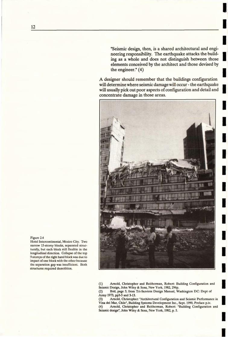
Figure 2.4Hotel Intercontinental, Mexico City. Twonarrow 15-storey blocks, separated struc-turally, but each block still flexible in thelongitudinal direction. Collapse of the top9 storeys of the right hand block was due toimpact of one block with the other becausethe separation gap was insufficient. Bothstructures required demolition.
4
1
bA
(1) Arnold, Christopher and Reitherman, Robert: Building Configuration andSeismic Design, John Wiley & Sons, New York, 1982, 296p.(2) Ibid, page 5; from Tri-Services Design Manual, Washington DC: Dept ofArmy 1973, PPM and 3-13.(3) Arnold, Christopher. "Architectural Configuration and Seismic Performance inVina del Mar, Chile", Building Systems Development Inc., Sept. 1990, Preface p.iv.(4) Arnold, Christopher and Reitherman, Robert: "Building Configuration andSeismic design", John Wiley & Sons, New York, 1982, p. 5.
12
3 4

Implications of New Zealand Codes
The philosophy behind modern seismic codes of practice is firstand foremost to prevent serious injury to people within, or closeto buildings, by preventing complete structural collapse. How-ever, while buildings will remain standing in a major earthquake,considerable structural and non-structural damage will almostcertainly occur.
fifa
3.#Em- ·=s-i1 //glf ...1.
H.11 :1....'uil
%6 -44 - ........#%6 ...m».*.......
I
-4*:N.tror
Figure 3.1
Exterior non-structural damage to 22-storey steel-framed office building whichwas one of five towers forming the Pino
Suarez complex in Mexico City. 45*".':.. 20? „ '07. 94.-//
The design of non-structural elements is important in two waysthat are both recognised in New Zealand seismic design codes:
e Firstly, non-structural elements must be detailed so thatthey do not contribute in an unplanned wayto thebuildingsseismic response.
e Secondly, they should be detailed so that damage to thenon-structural elements themselves is kept at acceptablelevels.
13
3

What is acceptable in this context will vary according tobuilding type, and can be open to some debate; although a cleardistinction can be made between (say) a clvll defence headquar-ters, which must remain functional in the period after an earth-quake, and a typical office building, where the first concern is thatpeople should be able to evacuate the building safely.
Loadings Code At the time of writing NZS 4203 : 1984, the Loadings Code, ( 1)is used by alllocal authorities in New Zealand as their bylaw forearthquake resistant design. While the control regime willchange once the new Building Act is in force, a version of the codewill continue to be the principal verification method for seismicdesign under the proposed new national Building Code.
NZS 4203 : 1984 contains design force requirements for non-structural elements on, or in buildings, as well as inter-storey driftlimits for the main lateral force resisting structure. Minimumseparations between buildings are also included, and there is aspecial section on suspended ceilings. Each of these require-ments is briefly reviewed below.
Design Forces Design forces on non-structural elements and their connectionsare addressed in section 3.4.9 of the code - Parts or Portions.
The important thing for architectural designers to realise is thatthere are stringent requirements on the design of items such asexterior panels, veneers, and appendages (such as big signs,forinstance). Therefore, the engineer needsto be consulted at anearly stage in their design.
Figure 3.2
Precast concrete cladding panels beingcrected in Mexico City, 1985. This photoshows how NOT to do it! The poorlyengineered details makes no provision forlateral movement in either the top or bot-tom flxing. Refer section 5 for informationabout how to do it.
14
There are also code requirements for connections of elements,which affects fixings for curtain walls, for example, as well as theattachment of heavier items like precast concrete panels. Again,early engineering input is advisable.
Drift and
Separation
Inter-storey drift and separation of non-structural elements iscovered in sections 3.8.3 and 3.8.4 of the code.
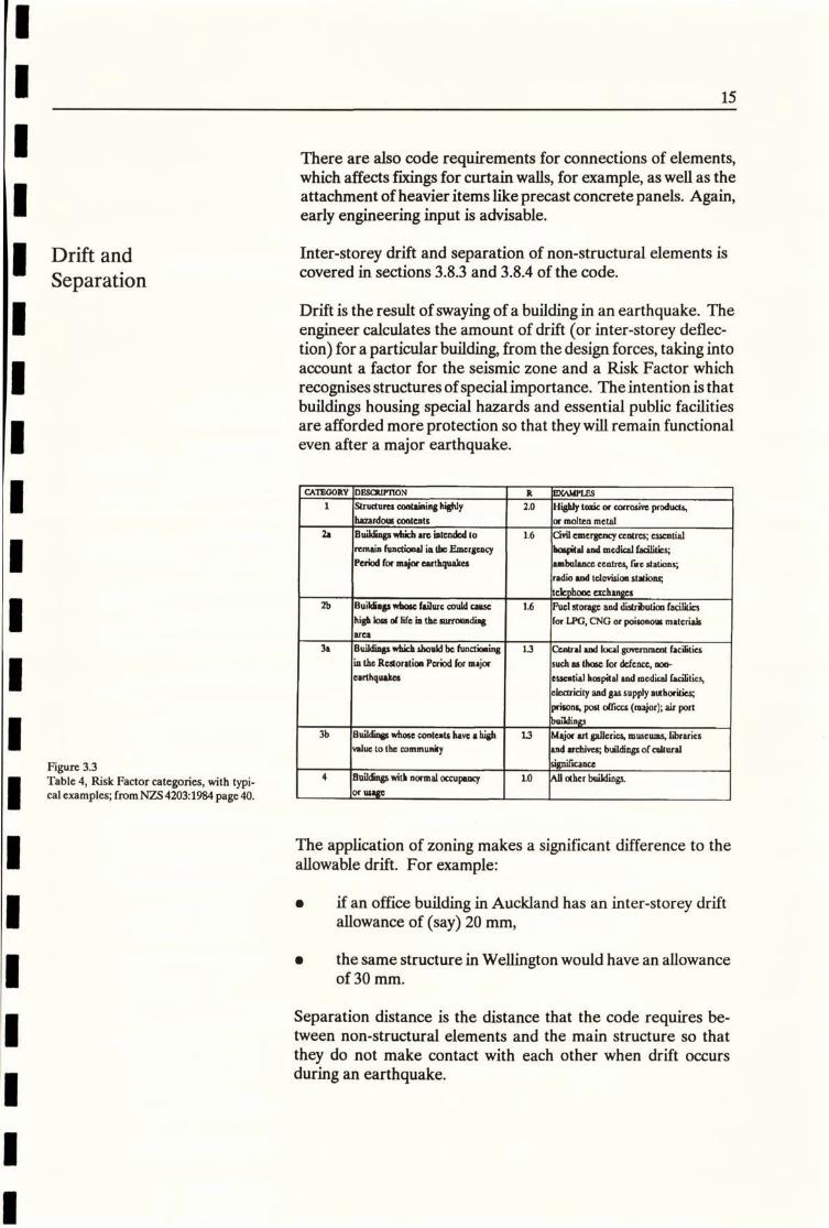
Drift is the result of swaying of a building in an earthquake. Theengineer calculates the amount of drift (or inter-storey deflec-tion) for a particular building, from the design forces, taking intoaccount a factor for the seismic zone and a Risk Factor which
recognises structures of specialimportance. The intention is thatbuildings housing special hazards and essential public facilitiesare afforded more protection so that they will remain functionaleven after a major earthquake.
CATEGORY DESCRIFTION R EXAMPLES
Figure 3.3
Table 4, Risk Factor categories, with typi-cal examples; from NZS 4203:1984 page 40.
1 Strudures containing»]yhaza,dous contents
2. Building. which arc intended toremain functiocal in th= Emergency
Period for maior earthquakes
2b Buill.gs whose failure could causehigh loss oi life in thesurroundi•g
arca
Ja B•„twns. which shoild b¢ lunctioaing
in the Restoration Period for major
earthquakes
3b Buildi,5 whose contents have a highValuc tothc community
4 Buildings with normal occupancyor Ulage
2.0 Highly toxic or corrosive products,
or motten metal
1.6 Civil emergency centres; cuentill
holpilal and medical facilities;
ambulancc centres, 1,c stations;
radio and television stations;
telephone exchanges
1.6 Fuel storage and detrinutioo facililics
for LPG, CNG or poisonoul matcriab
13 Central and local government facilitia
such as thoic for defence, non-
esscatial hospital and medical facilities
elect,icity and gas supply aihoritics,
prisons, post offica (major); air port
buildings
U Major art galleric4 museums, librariesand archives; buildings of cultural
significance
1.0 All other buildings.
The application of zoning makes a significant difference to theallowable drift. For example:
• if an office building in Auckland has an inter-storey driftallowance of (say) 20 mm,
I the same structure in Wellington would have an allowanceof 30 mm.
Separation distance is the distance that the code requires be-tween non-structural elements and the main structure so that
they do not make contact with each other when drift occursduring an earthquake.
15

I FTE'#MZ":*@ 11.11 ...+1,4... i +Jf }'i'2.1,11
; , j :i!'11!1!1 !;' i[!i=!lii!!li11!;i!11;' -: n '!ijl:j!!!!11!it!!:il;111111'!! t'h':,1 j liE, /I ,;.1.!!1!Ii':;i!i:!i:!#Ali,.Ii:!i:i :i::::: '. ............:':TE.! i j. il!!i!!Ii!5!1!!iii!Ii!iii:!i.:i!:iIl '!;11!'i!+0•i:!lililliliti!11111!111!lit!1,1111111]lill.Ij.NK.Mul{Iiffii1;iiifij#,,Ff=1!11• ,I 1/Il,!5,ill.P 1 iti·,il,·4:iii:i··8®RB'BRRM*r.:i· ·h·iNHNJJA·EE·f'DE::: t!:ili,tww4!!D,:i·Idi'*WI...I."IN.I.I"j"'It• i1 I ,111*.9,','Iil'.1,9Inwi,/18@'"".".",..,'.'.''.'.'."Wi"81 I i
1
Figure 3.4
The diagram shows, in an exaggerated way,the flexure of a framed structure under - Llateral loading and the clearances required -,
r-around an infill panel to avoid it makingcontact with structure. 1
---
Ml I*tiFTWU! '.lit:!:1:11%!IN'1%%%..1,hwil"Jwil.I
]11.i l'iIll;li1 ill·'lllii·Ill i.lili;;::1iili:!i'42:13·:+i:• ·'i::.·i:I'll:Il.ii : i!1 i!;il +1ijj i '1!ell.11111111111i 1'I!:;!,i'!p.!Illilil:111'©id·111!:i!:·i.iii;:;i·i:i.ii·F9·'1019%92*
1:$,
:I/l
B illl
-+ r-
Separation Limitsand Application
When drift is less than 0.006 times the storey height, then noseparation is required. This typically allows only 2 mm ofmovement between floors and in practice only applies to very stifflow-rise buildings
Drift of more than 0.010 times the storey height is not permitte-din the highest risk zone, i.e. more than 36 mm in a buildinghaving 3.6 m between floors.
Most buildings fall between these limits and so separation fordrift needs to be seen as a normal requirement in the design of:
e Precast concrete claddings and other claddings of similarmass.
e Glass and other rigid, brittle exterior claddings (except invery low risk situations).
Stairways
. Rigid partitions and infill panels - that is those that aresufficiently stiff that they are capable of altering thestructural response of the building to a significant degree.
In practice most buildings in which seismic drift is significantrequire at least 20 mm separation, plus and/or minus, i.e.
Details must allow for a total of 40 mm movement, in this case,
as the structure sways backward and forward.
16
11--------4 L.

Ductility It is important to mention the significant differences betweenstiff and flexible structures, as this has a bearing on the selectionof a structural system in the first place - as well as on theprovisions that may have to be made for drift. Ductility is aword often used by engineers when talking about these matters.
Ductility means the ability of the building or a memberin a building to undergo repeated and reversing in-elasticdeflections, beyond the point of first yield, while maintain-inga substantialproportion ofits initialmaximum load car-rying capacity. (2)
We are allfamiliarwith the idea ofelasticdeformation. When we
stretch a rubber band, or bend a thin rod (but not too much) itreturns to exactly its original state when released.
Buildings too behave elastically, to some degree, but there areobvious practical limits to a buildings flexibility. On the otherhand, a building designed to be so stiff that it will not deflectbeyond the elastic limit at all, even in a large earthquake, willusually be uneconomic.
Figure 33Variations in ductility Steel is shown onthe left and concrete on the right. Steelfails only after considerable in-elastic de-formation has occurred, whereas unrein-forced concrete is a brittle material and
fails suddenly when its elastic limit isreached. However, reinforcing steel con-tained in concrete can give the compositemember considerable ductility· The act ofdeformation absorbs energy and defersfailure of the concrete.
Strain Strain
Ductile Brittle
It is therefore likely that, for a real building in a moderateearthquake, structural deformations will enter the in-elasticrange, and some ductile yielding will occur. This is acceptableprovided that the damage, if any, is limited and occurs in con-trolled locations, usually in the beams, at points away from theirintersection with the columns, or possibly at the base of shearwalls.
Why? Because experience has shown that, in a major earthquake,most catastrophic building failures occur when columns fail.Rarely do buildings literally fall over. Hence, the seismicengineers adage:
Strong columns and weak beams - not the other wayaround
17
tily 1
, 2,2
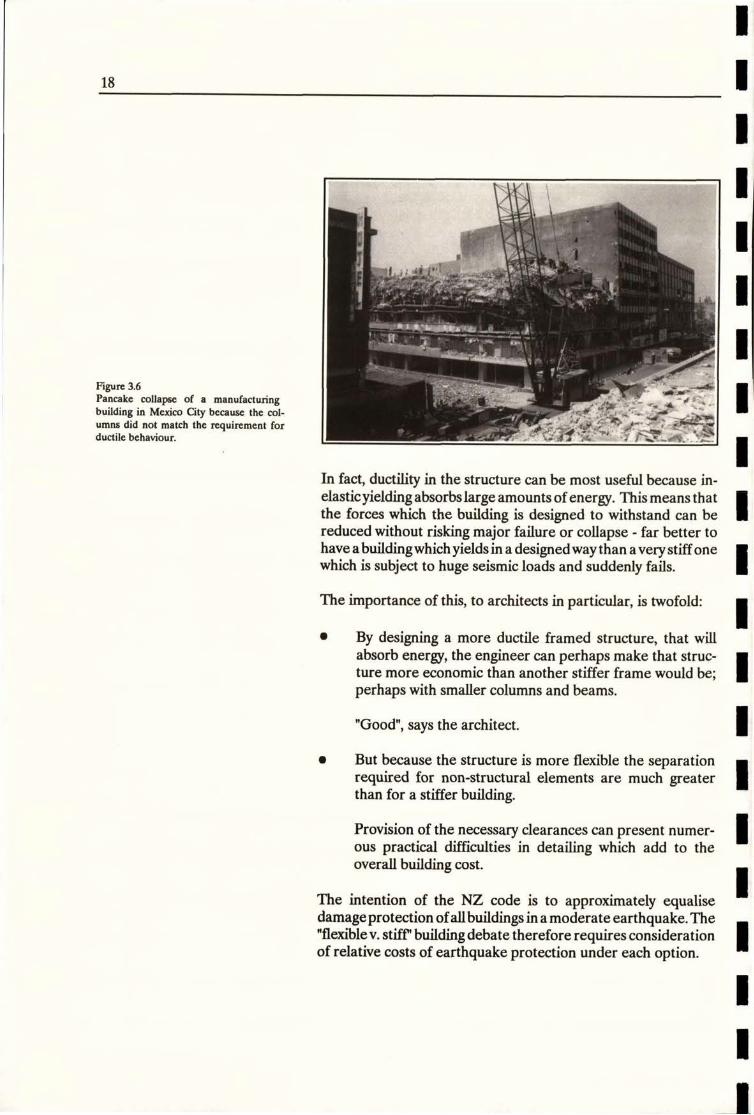
Figure 3.6
Pancake collapse of a manufacturingbuilding in Mexico City because the col-umns did not match the requirement forductilc behaviour.
. 2 / 2/44-
In fact, ductility in the structure can be most useful because in-elasticyielding absorbslarge amounts ofenergy. This meansthatthe forces which the building is designed to withstand can bereduced without risking major failure or collapse - far better tohave abuilding whichyields in a designed waythan a very stiff onewhich is subject to huge seismic loads and suddenly fails.
The importance of this, to architects in particular, is twofold:
• By designing a more ductile framed structure, that willabsorb energy, the engineer can perhaps make that struc-ture more economic than another stiffer frame would be;perhaps with smaller columns and beams.
"Good", says the architect.
• But because the structure is more flexible the separationrequired for non-structural elements are much greaterthan for a stiffer building.
Provision of the necessary clearances can present numer-ous practical difficulties in detailing which add to theoverall building cost.
The intention of the NZ code is to approximately equalisedamageprotection ofallbuildings in amoderate earthquake. The"flexible v. stiff" building debate therefore requires considerationof relative costs of earthquake protection under each option.
18

Ceilings In New Zealand ceilings should be designed for horizontalaccelerations and mention is also made in the code of vertical
accelerations, which are often nearly as large. Thus, heavy ceilingtiles can be dislodged. Suspended ceiling hangers are not re-quired to be designed for compression caused by upward accel-erations but connections must be able to sustain upward move-ments without disengagement. The connection oflight fittings toceiling systems must provide positive anchorage. (3)
Figure 3.7
Failure of a very lightly framed suspendedceiling system in the Secretariat of WaterSupply, Mexico City. Note the inadequatewire hangars. L
Other NZ Codes The code Seismic Resistance of Engineering Systems in Build-ings, NZS 4219,(4) was introduced in 1983. The code specifiesseismic design requirements for equipment and their fixings inbuildings, with emphasis on services and other aspects not cov-ered by this handbook.
The former Ministry of Works had their own Public BuildingSeismic Design Code, PW 81/10/1,(5) which contained specialseismic requirements for buildings funded by Government. Thecode contained more stringent requirements than NZS 4203 forthe protection of non-structural components, including exteriorelements, windows, heavy rigid and lightweight partitions, sus-pended ceilings and stairs. Recommendations on materials bestsuited forelement connectionswere included. Atthe time(1976)this code was more detailed than any other with regard to non-structural element design and detailing.
A more thorough review of the New Zealand code recommenda-tions and their derivation is given in an article in the Bulletin ofthe NZ National Society for Earthquake Engineering, March1985, by Hopkins, Massey and Pollard.(6)
19

20
NZS 4203:1984, Code of Practice for General Structural Design and Design Loadings for Buildings
(2) Ibid, Definitions, page 12.
(3) Ibid, cl. 3.63, P56.
(4) SANZ,NZS 4219:1983, Specification for Seismic Resistance of Engineering Systems in Buildings, 37p
(5) Ministty of Works and Development NZ, Code of Practice-Seismic Design ofPublic Buildings, Office of the Chief Structural Engineer, PW 81/10/1, 1976.
(6) Hopkins, D.C; Massey, W.E; Pollard, J.L.: Architectural Elements in Earth-quake, A Review of Design and Construction Practice in New Zealand, Bull. NZNSEE,Vol. 18, No. 1, March 1985, pp21-40.
1
1
1
1
1
1
1
1
1
1
1
1
1
Structure and External Walls
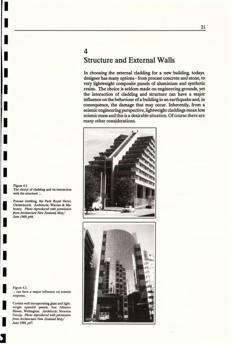
In choosing the external cladding for a new building, todaysdesigner has many options - from precast concrete and stone, tovery lightweight composite panels of aluminium and syntheticresins. The choice is seldom made on engineering grounds, yetthe interaction of cladding and structure can have a majorinfluence on the behaviour of a building in an earthquake and, inconsequence, the damage that may occur. Inherently, from aseismic engineering perspective, lightweight claddings mean lessseismic mass and this is a desirable situation. Of course there are
many other considerations.
Figure 4.1The choice of cladding and its interactionwith the structure ...
Precast cladding, the Park Royal Hotel,Christchurch. Architects: Warren & Ma-
honey. Photo reproduced with permissionfrom Architecture New Zealand, May/June 1989, p64.
21 1.1
St
Figure 4.2
... can have a major influence on seismicresponse.
Curtain wall incorporating glass and light-weight spandril panels, Sun AllianceHouse, Wellington. Architects: StructonGroup. Photo reproduced with permissionfrom Architecture New Z,ealand May,/June 1989, p67.
i.
21
4

Structural Types Just as the architect has a wide choice of materials to draw upon,so there are many options available to the engineer when design-ing the structure; choices between reinforced concrete and struc-tural steel; betweenprecast and insitu elements, and where to useeach; the type of framing system, i.e. the disposition of columnsand beams, shear walls - and so on.
But for simplicity this section mentions only three basic structuraltypes:
I Stiff structures.
e Flexible structures.
e Special solutions.
Stiff Structures All building structures are subject to some degree of lateralmovement in a moderate earthquake but in a very stiff structurethe degree of movement will be small.
In Section 3 it has already been seen that the code requires sepa-ration of non-structural elements if calculated lateral movement
is more than 2 mm floor to floor. Such small movement is uncom-
mon, except in very stiff low-rise structures.
Many old buildings are rigid and brittle because their traditionalconstruction, (thick masonry walls with small window openings)is initially unyielding. This makes them veryvulnerable to the sortof earthquake shaking they are likely to experience in most partsof New Zealand. Very large loads seek out weak points - such asglazed shopfronts at street level, or cavity brick panels, whichcrack or are crushed.
Buildings constructed in the early part of this century often useda form of steel or reinforced concrete framing, but this wasoverlaid with traditional facade construction. Unless such build-
ings are strengthened they can be very vulnerable to earthquakeattack, due to inadequate toughness in the structural elementsand connections, plus interaction between the frame and thefacade elements.
22
23
*ti 4/
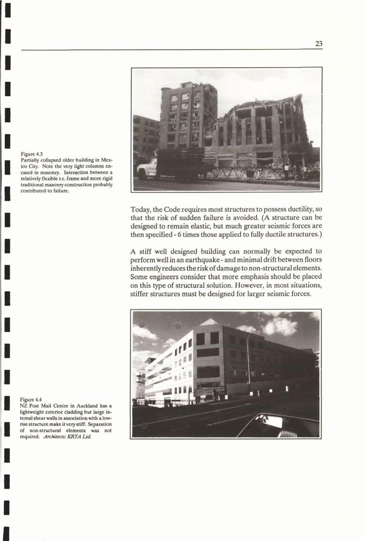
Figure 4.3
Partially collapsed older building in Mex-ico City. Note the very light columns en-cased in masonry. Interaction between arelatively flexible r. c. frame and more rigid
traditional masonry construction probably Wcontributed to failure.
3117*99*1.
Today, the Code requires most structures to possess ductility, sothat the risk of sudden failure is avoided. (A structure can bedesigned to remain elastic, but much greater seismic forces arethen specified - 6 times those applied to fully ductile structures.)
A stiff well designed building can normally be expected toperform wellin an earthquake - and minimal drift between floorsinherently reduces therisk of damageto non-structural elements.Some engineers consider that more emphasis should be placedon this type of structural solution. However, in most situations,stiffer structures must be designed for larger seismic forces.
Figure 4.4NZ Post Mail Centre in Auckland has a
lightweight exterior cladding but large in-ternal shear walls in associationwith a low-
rise structure make it Vely stiff. Separationof non-structural elements was not
required. Architects: KRLA Ltd.
I -
J.
4

Flexible Structures Nowadays most medium and high-rise buildings are of this type and usually consist of a framework of beams and columns alongeach major axis. Lateral stiffness is generally provided by frame action, with the floors acting as diaphragms to distribute horizon- 1talloads. If shear walls, or coupled shear walls, are incorporated
they will add stiffness and such options need to be considered. There may be pronounced drift between floors in an earthquake(up to 36 mm in a 3.6 m interstorey height is allowed under the current code). Potentially greater movement will occur if future Icodes allow even more flexibility, especially in steel structures, in
the interests of lighter sections and hence structural economy. Flexible structures that are designed for ductility offer a widerange of opportunities to the architect in terms of planning andarchitectural treatment. They can be designed to produce daring architectural results but early engineering consideration is amust.
A disadvantage is that, drift between noors can become increas-ingly difficult to accommodate. If movement is not provided forthen earthquake damage will certainly result.
1
Figure 43
The 40 storey Marriott Hotel, San Fran-cisco, in the soft soil area south of Market
Street, covers most of a city block and hasenormous four storey high reflective glassdecorative fans at roof level. It suffered
one broken pane of glass during the 17October 1989 Loma Prieta earthquake(Richter magnitude 7.1). (Source: Peny,AIan San Francisco Earthquake Re-port, Architecture New Zealand, May/June 1990, pp 89-90.)
Architects: DMJM, San Francisco
Photo: Peter Leach, Philadelphia
24
1
1

Cantilever shear walls and coupled shear walls are also usuallydesigned for ductility so that plastic hinges can form at theirbases, and in the couplingbeams. Themajor advantage ofductilewall systems (compared with ductile frames) is that their inter-storey drifts are considerably less. However, because of theirgreater stiffness they attract greater earthquake forces.
till
shear walls - 4Figure 4.6 --NEC House in Grafton Road, Auckland /Zill---=-fl-----:-7.uses a combination reinforced concrete frame
shear walls and beam/column frames. It is - -typical of many medium rise office build-ings crected in the 19806. Seismic move- 111=fimmulj..1/- frame
CAN;3%71%.Atclocrtain --i =¥7-V*Z==--=-T-1 1
Architects: KRTA Ltd.
===21
7-==,=
Special Solutions Seismic engineering research is on-going and new ways of pro-tecting buildings are being developed.
A relatively new approach (at least in actual application inbuildings) is base isolation, by which a structure can be separatedfrom its foundations using special devices, such as a combinationoflead and rubber called base isolators, orother forms ofenergydissipator. Depending on site conditions these devices maygreatly reduce the loads due to ground movement that are trans-mitted to the superstructure. Inter-storey drift may be reducedso that separation of non-structural elements is deemed un-necessary.
Base isolation techniques have been used in a few buildings inNew Zealand and onanumber ofotherstructures, such asrailwayviaducts. In the future base isolation offers promise for theeconomic preservation of historically important masonry build-ings. It could be an alternative to more extensive (and expensive)strengthening techniques, which may be unsuitable when tryingto retain architectural and historical character.
25
19 'i . 'p' l]RA 101„.4.,NI
%%4 91€ ff 20201,0 liR/1
Lt,F#*MY,i' 9/1 5,6 7* lip"i;"444/ 2i:1224%.i 4 d.. :1-..=I#/Remjll
imr :i··· 'i!·4 ;4 i:;····· ._6. /*Cill/41/7*/
1 , i·iii!
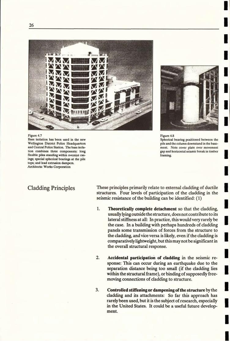
Figure 4.7Base isolation has been used in the new
Wellington District Police Headquartersand Central Police Station. The base isola-
tion combines three components: longflexible piles standing within oversize cas-ings; special spherical hearings at the pile
tops; and lead extrusion dampers.Architects: Works Corporation
Figure 4.8
Spherical bearing positioned between thepile and the column downstand in the base-ment. Note cover plate over movementgap and horizontal seismic break in timber
framing.
Cladding Principles These principles primarily relate to external cladding of ductilestructures. Four levels of participation of the cladding in theseismic resistance of the building can be identified: (1)
1. Theoretically complete detachment so that the cladding,usuallylyingoutsidethe structure, does not contribute to itslateral stiffness at all: In practice, this would very rarely bethe case. In a building with perhaps hundreds of claddingpanels some transmission of forces from the structure tothe cladding, and vice versa is likely, even if the cladding iscomparativelylightweight, but thismaynotbe significant inthe overall structural response.
2. Accidental participation of cladding in the seismic re-sponse: This can occur during an earthquake due to theseparation distance being too small (if the cladding lieswithin the structural frame), or binding of supposedly free-moving connections of cladding to structure.
3. Controlled stiffening ordampening ofthe structure bythecladding and its attachments: So far this approach hasrarely been used, but it is the subject of research, especiallyin the United States. It could be a useful future develop-ment.
26
4. Full integration ofthe cladding into the structural system:Where the cladding and the structure are homogeneous, asfor instance when insitu concrete walls are used, the resultsare predictable and the cladding becomes part of a shearwall system. It is also technically possible to achieveintegration using precast components, at least in low-risesituations. But in practice this approach has not beenwidely employed. It is seldom that the architectural clad-ding design is fully compatible with the structural concept:If it is not, then configuration problems can arise.
In practice, therefore, detachment of cladding has remained byfar the most common approach, despite its inefficiency - in thesense that more economical and seismically efficient structurescould be produced by integration.
(1) Source: Arnold, C *Cladding Design: Recent Architectural Trends and TheirImpact on Seismic Design" Proceedings, 'Architectural precast cladding - its contributionto lateral resistance of buildings" Chicago, Nov. 1990, p.29-30.
27
External Wall Types
External walls can be:
e Structural walls - of reinforced concrete, precast concrete,masonry, timber, steel - or even rammed earth!
I Integrated infill panels, designed to be a part of the mainstructure.
I Separated infill panels, not considered part of the mainstructure.
I Facing materials, which clad the main structure but shouldbe effectively detached from it for seismic design purposes.
This section deals mainly with facing panels, as it is their detailingthat is most frequently of concern in the design of larger buildings
for earthquake.
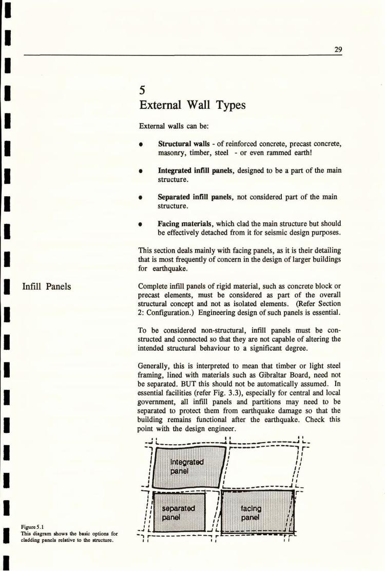
Infill Panels Complete infill panels of rigid material, such as concrete block orprecast elements, must be considered as part of the overallstructural concept and not as isolated elements. (Refer Section2: Configuration.) Engineering design of such panels is essential.
To be considered non-structural, infill panels must be con-structed and connected so that they are not capable of altering theintended structural behaviour to a significant degree.
Generally, this is interpreted to mean that timber or light steelframing, lined with materials such as Gibraltar Board, need notbe separated. BUT this should not be automatically assumed. Inessential facilities (refer Fig. 3.3), especially for central and localgovernment, all infill panels and partitions may need to beseparated to protect them from earthquake damage so that thebuilding remains functional after the earthquake. Check thispoint with the design engineer.
0 1
-J L.
7 r-
11
i'*.wi...unmwn""Mo.M"'m r-1 Al'EminM@"Immi I
Figure 5.1
This diagram shows the basic options for .cladding panels relative to the structure.
,; 1, I.*00#tated i . E : facing *BE t,lI
41 L. :i*11„ r =' L..E-NE+L =1-26'L1 r--- --------9 r------------Ir1 1 , 1 11
29
5

Heavy Facing Panels Infill panels are usually built up from unit masonry (concreteblock or brickwork), but facing panels are commonly large units,often covering the full width of a structural bay for a storey height.Construction handling is a major determinant in sizing such
panels - either because weight must be limited (usually for easeof cranage), or because over large panels become impractical tohandle.
When large heavy facing panels are used provision for seismicmovement becomes critical. This is usually achieved by havingfixed bearing connections at the top of the panel and providing forlateral movement in detailing the bottom fixings. But theselocations are sometimes reversed. The fire rating of fixings can bean important consideration.
:*.:. ·:.: bearing connections....:¥
: : facing panel f
c* : movement connections :]clf: A
Figure 5.2
Top and bottom bearing connections forfixing facing panels.
::: movement connections :I:*u..
»:.:9:1::.:.:24: facing panel .:: :: 6::-·Tic6*
bearing connections::::.·., '-
Connections Two common types of connection have been developed to allow
for movement between heavy panels, such as precast concrete,and the main structure.
e Rod connections, which are the most common type in WestCoast USA.
I Sliding connections, which have been widely used in NewZealand and elsewhere.
Neither approach is without disadvantage and, in each case,predicted performance is based on engineering principles ratherthan observed performance after an earthquake, or even exten-sive laboratory testing.
I Rod connections. These are commonly referred to in USAas ' push-pull' connections. The rod and connector detailsmust be tough enough to withstand imposed loads, both onthe face of the panel and ' in plane'; yet the rod must be long
30

and flexible enough that it will remain ductile over the
predicted range of movement. If the panels are to be fixedclose to the structure this may be difficult to achieve.
safety connection/ bearing removed after panel
/ connection installation
Figure 5.3
Rod (or push-pull') connections to pro-vide for movement. Typical details for 4=9 1steel structure Con left), concrete structure . .:
..... ..r
on right. Note that fire protection offixings i f 2 .. ·:.is not shown on these details and may be . 3 ... e . .. :1required. I . 4!
Redrawn with permission from ' ' SeismicDesign of Architectural Elements" Build-
ing Systems Development Inc., KRTALimited, Forell/Elesser Engineers Inc.,March 1987.
25 threaded rod
ductile connection
*--40 !
UL
' Push-pull' connections seem to have performed well, but some
queries about their long-term effectiveness have been raised.The connection of the rod to the panel is particularly critical. (1)
I Sliding connections are usually provided by using cleats tojoin the panel to the structure. Each cleat is bolted through
a slotted hole to provide for movement. Disadvantages ofthis system are:
- movement will not occur i f the cleats bind' due to
misalignment during construction or flexure of thecomponents under load, or ' seizing' of the detail overtime (due to rust).
- bolts may be overtightened so that lateral loads aretransferred through the connection.
Sliding connections are best kept to situations in which the degreeof lateral movement in each connection is small, e.g. stifferstructures, or panels of reduced height.
(1) Rihal, Satwant, S. : "Earthquake Resistance and Behaviour of ArchitecturalPrecast Cladding and Connections". Proceedings; ' Architectural precast cladding - itscontribution to lateral resistance of buildings"; Chicago, Nov. 1989, pp 1 10-140.
31

**'--7. 2. movementb....01-6-- connection
....
- bearingconnection -
Figure 5.4
Two examples of sliding connections to
precast panels. The example on the left hasthe panel bearing on a concrete corbel at
mid-height, with movement connections attop and bottom of the panel. Movement ineach connection is therefore reduced.
The example on the right is of a precastpanel only 940 mm high, so provision formovement is limited.
movement
. connection
Movement can also occur at right angles to the panel face (or atany other angle, depending on the direction of the drift in thestructure). Connections must allow for this movement.
-1-
movement connection -
panel
+ 4-bearing connection
7-t It
I n-plane movement ofstructure relative to panel.
Movement at right anglesto plane of panel.
Figure 5.5
In-plane and out-of-plane movement ofstructure relative to panel.
Finally, the designer must be aware of the relative movement ofpanels at corners, both internal and external, so that drift does notlead to impact between panels at these locations.
32
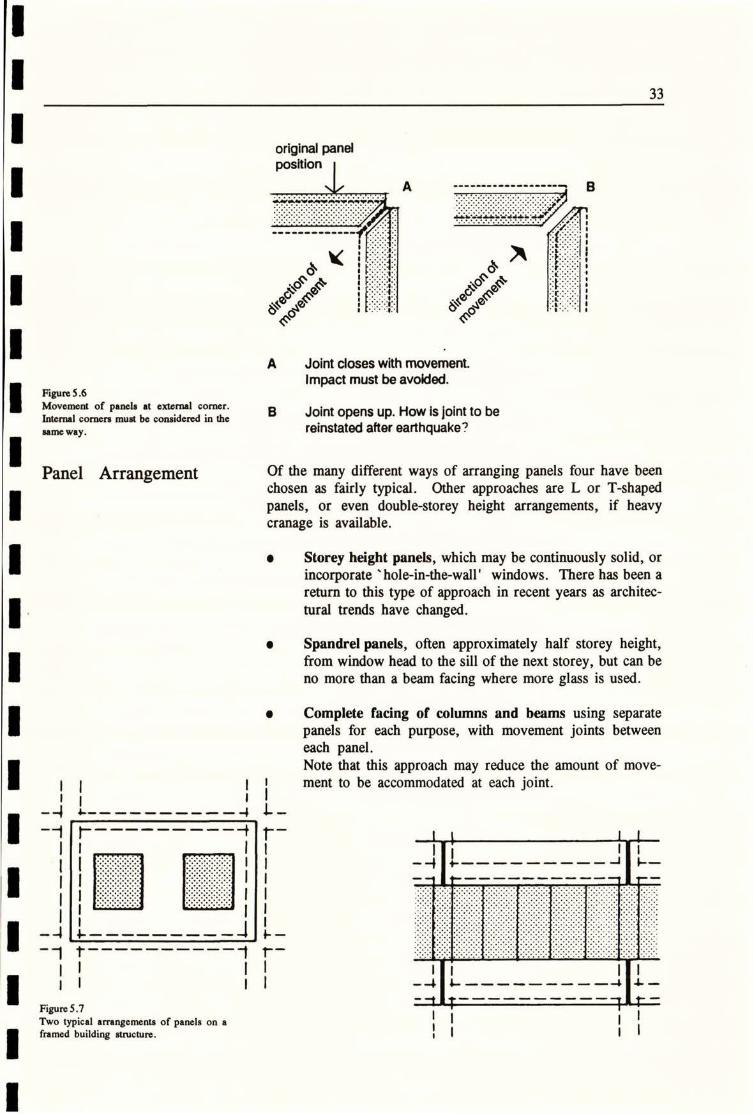
original panel
position A ------------------ B
ffy,
1
£,1e
A Joint closes with movement.
Impact must be avoided.Figure 5.6
Movement of panels at external corner. BInternal corners must be considered in the
same way.
Joint opens up. How is joint to bereinstated after earthquake?
Panel Arrangement Of the many different ways of arranging panels four have beenchosen as fairly typical. Other approaches are L or T-shapedpanels, or even double-storey height arrangements, if heavycranage is available.
Storey height panels, which may be continuously solid, orincorporate ' hole-in-the-wall' windows. There has been areturn to this type of approach in recent years as architec-tural trends have changed.
I Spandrel panels, often approximately half storey height,from window head to the sill of the next storey, but can beno more than a beam facing where more glass is used.
Complete facing of columns and beams using separatepanels for each purpose, with movement joints between
each panel.
Note that this approach may reduce the amount of move-ment to be accommodated at each joint.
11 1111 11
--1 k-
1 1 -1 --- --- --11
1 Zt----------1 M-
11 11 li 1111 11 -4 &----------4 4-
Figure 5.7
Two typical arrangements of panels on aframed building structure.
33
11 114 L-----------1 L- --1 1 --------1 L-
11 11
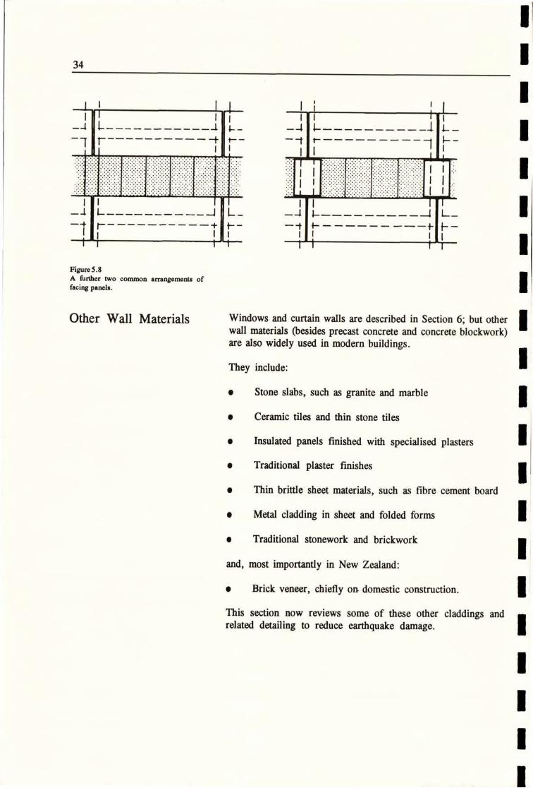
11 11 1Figure 5.8A further two common arrangements offacing panels.
Other Wall Materials Windows and curtain walls are described in Section 6; but otherwall materials (besides precast concrete and concrete blockwork)are also widely used in modern buildings.
They include:
• Stone slabs, such as granite and marble
• Ceramic tiles and thin stone tiles
e Insulated panels finished with specialised plasters
e Traditional plaster finishes
e Thin brittle sheet materials, such as fibre cement board
e Metal cladding in sheet and folded forms
• Traditional stonework and brickwork
and, most importantly in New Zealand:
e Brick veneer, chiefly on domestic construction.
This section now reviews some of these other claddings andrelated detailing to reduce earthquake damage.
34
11 11 l i 1111 11 11
4 L----------4 L-
-1 r---_______-+ E-11 1
I l
11 11.
tl
··1 '....t·, '.-dr.--11 hit·.:
=...
'Nj
b
lIE
m -:1 -91™1@%2r ?5
Plf V
r.,4 4
.:; t'APKil....
f-*tdy'•e
31911?V
*I
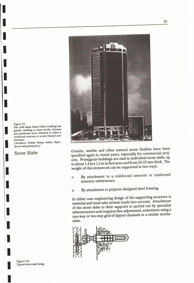
Figure 5.9 -mwriThe ASB Bank Head Office building hasgranite cladding to foyer levels, columnsand penthouse level, attached to either areinforced concrete or a steel framed sub-structure.
[Architects: Peddle Thorpe Aitken. Repro-duced with permission.]
k·#4./. -4'LA'.1.-4
Stone SlabsGranite, marble and other natural stone finishes have beenspecified again in recent years, especially for commercial proj-ects. Prestigious buildings are clad in individual stone slabs, upto about 1.4 mx 1.2 m in face area and from 20-25 mm thick. Theweight of this stonework can be supported in two ways:
o By attachment to a reinforced concrete or reinforcedmasonry substructure.
o By attachment to purpose designed steel framing.
In either case engineering design of the supporting structure isessential and must take seismic loads into account. Attachmentof the stone slabs to their supports is carried out by specialistsubcontractors and requires fine adjustment, sometimes using aone-way or two-way grid of lipped channels or a similar mecha-nism.
*So ·3244,411
.Mr-4444..-tll....U-14•-
34*hfy:916%4€-
Figure 5.10Typical stone slab fixing.
35
LM:™11

structure .
two Way <Figure ill channel gridTwo-way grid oflippcd channels foradjust-ment of stone slab fixings.
The architect can therefore rely to a substantial extent on the
knowledge of others, which must be sought at an early stage. In the main, drift is provided for by assuming small incrementalmovements will occur in each horizontal joint. Joints are filledwith a resilient sealant, such as polysulphide. Because there are a large number of joints, relatively closed spaced, and often afairlystiff substructure, specially designed separation ofpanels ofstonework may not be required, BUT consult the design engi- 1neer.
L4'U
REMFigure 5.12
An Auckland office building clad in ce-ramic tiles mounted on panels.
[Architects: Andrews Scott Hill. Repro-duced with pennission.]
Ceramic Tiles Both these materials are supplied in small unit sizes, up to 300 mm x 300 mm x 12 mm thick. As a wall cladding they can beThin Stone Slabsmounted in three ways:
o Traditional mortar bed over a rigid base (such as insituconcrete or masonry) with a good key. Because the baseis rigid, joints between individual tiles can be grouted, but the base itself is often a non-structural element, e.g. a
36
1
1

reinforced masonry infill wall. In that case, seismic move-ment must be provided for in tile joints over the separationgap. Flexible sealants are used for this purpose, over abacking rod.
flexible sealant
/- bond breaker
ceramic tile
4. // non-structural
,/, masonry panel'lil,
lil ,1I,1I
iILI{IFigure 5.13 ,
A flexible scalant joint of sufficient widthto allow for drift ia required at the junctionof structural and non-structural elements.
h/111 / 14 Nfl 1 1 7,44,11,1 1 1
Adhesive fixed to a stable board substrate, which is in turn
fixed to a metal or timber frame. If the framing is non-structural, then it must be separated from the mainstructure, and movement joints provided, similar to Figure5.13.
Proprietary tile fixing systems. When using these systemsin New Zealand, the requirements for earthquake move-ment must be specified so that allowance for any specialdetails can be made in pricing. Such systems have oftenbeen developed in countries that do not have earthquakedesign requirements.
- RlvetCalvanlied Steel Stud
Sillcon• Caulking4/l////ll///////////
--Spacer TapeFLOOR TO FLOOR PANEL
-Sit Back Windows
[Reproduced with permission Jrom NZ Con-tracting Ltd.J
Galvanlsed Steel Docking
Structural Sillcone
Galvanlied Steel
Perimeter Frame
Figure 5.14 .-4 --
Manufacturer's literature on a proprietary tile fixing system. Note scalant in paneljoint to allow for movement. The width of ithisjoint must relate to ' drift' of the struc-ture relative to height of the panel.
_Sillcon, Sealant withBacker Rod
Cladding
PANEL TO PANEL JOINT
37

Plastered Wall Finishes Whether traditional plastering techniques are used, or morerecently developed proprietary systems, provision for movementneeds to be made where framed panels are seismically separatedfrom the main structure. there are no ' standard' details for such
situations so the architect draws on good construction principles.
Thin Brittle Sheets Materials such as fibre cement board are widely used for wallcladding in commercial, industrial and residential work. It iscommonly assumed that no separation of such materials isrequired and on stiffer low-rise structures this approach is rea-sonable. Details often include open joints, or use PVC jointers,and some movement is provided for in this way if the framingbehind is slightly racked.
Specific detailing for seismic movement becomes important onhigher rise, more flexible structures, especially if joints are closebutted or flushed up to provide a homogeneous finish. Clearlyreinstatement of such finishes could be required after a majorearthquake but, more importantly, detachment of the claddingcould occur if there are large inter-storey drifts.
Thin sheet cladding is often fixed to timber framing, which infillsthe main structure. Separation in this case is easily provided.
Note: NZS 4203 requires separation of brittle exterior claddingin these circumstances.
flexible brittlosealant sheet
column no fixing(see head detail)
PLAN DETAIL
Figure 5.15
Seismic detail, to protect brittle claddingmaterials arc not difficult to fabricate usingconventional timber framing.
.
beam
seismic head
(note gap)
SECTION DETAIL
38

Sheet Metal Cladding Sheet metal wall cladding seldom requires detailing for seismicdrift (except at seismic breaks between structural blocks). Thenature and fixing oflong-run trough section cladding, corrugatediron and the like, tends to ensure that movement will be accom-modated.
However, damage to one form ofstrip metal cladding, in the 1985Mexico City earthquake, is a reminder that earthquake move-ment can produce unexpected results.
Figure 5.16Strip metal cladding was lost from thisbank building during the September 1985earthquake in Mexico City, even thoughthe unseparated panels of brickwork didnot collapse.
38.
Masonry Masonry construction can be used for wall cladding in two ways:
I As infill panels in a framed structure - separation isrequired.
e As a structural material - in which case engineering designis required.
In recent years little use has been made of freestandingreinforced brickwork but design techniques are well devel-oped for buildings where fairfaced brick finish is requiredon both faces of a wall.
Reinforced blockwork of course continues to be a majorstructural material. Examples of the use of this materialfornon-structural walls are given in Section 8 - Partitions.
39
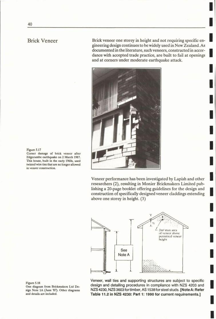
Brick Veneer Brick veneer one storey in height and not requiring specific en-gineering design continues to be widely used in New Zealand. Asdocumented in the literature, such veneers, constructed in accor-dance with accepted trade practice, are built to fail at openingsand at corners under moderate earthquake attack.
Figure 5.17Corner damage of brick veneer afterEdgecumbc earthquake on 2 March 1987.This house, built in the early 1960s, usedtwisted wire ties that are no longer allowedin veneer construction.
¥ 1i. hi: #,1 1
Veneer performance has been investigated by Lapish and otherresearchers (2), resulting in Monier Brickmakers Limited pub-lishing a 20-page booklet offering guidelines for the design andconstruction of specifically designed veneer claddings extendingabove one storey in height. (3)
4.
P a
<2/.21 2 ,\ .--12nil mar dre.t
of veneer :il)ove
permitted veneerheight
See
Note A
-111:1,1
7,1:I!1:.Bl.t*MA,44tl>-i i; ; It.:.
Figure 5.18
One diagram from Brickmakers Ltd De-
sign Note lA (June '87). Other diagramsand details are included.
Veneer, wall ties and supporting structures are subject to specificdesign and detailing procedures in compliance with NZS 4203 andNZS 4230, NZS 3603 fortimber, AS 1538 forsteel studs. [Note A: ReferTable 11.2 in NZS 4230: Part 1: 1990 for current requirements.]
40

Past deficiencies in the performance of brick veneers can beattributed to the common use of inadequate wall ties. The LaPalle tie connector transfers face loads from the veneer to the
structure, while catering for horizontal and verticalin-service andshort term deflections of the timber framing.
Figure 5.19Illustration of the La Palle flexible tic con
nector.
Where required, the tensile strength of panels may be increasedthrough the use of horizontal joint reinforcement in the mortarbedding, and, by incorporating vertical steel in the ports ofpurpose made knock-out-end bricks. Special attnetion should begiven to detailing at openings and at corners of reinforcedveneers.
FR=y
1 ' Proprictoly comsealer 10 +anufaqspecificattjns. j
Weather -
flashint /10
If-L 11 JFigure 5.20 ./21 1 KRe-entrant corner detail from Brickmak-
1 120 1ers Ltd Design Note lA (June 1989).
luDie
Building P:per
Wlivanised'R»hlin cont,ct
R> w-*b•*k with aL.WARABfus paint_,ar-1014 P,116 ductile
·.Nxible wall ties
41

1
42
(1) Rihal, Satwant, S.: *Earthquake Resistance and Behaviour of Architectural Prccast Cladding and Connections". Proceedings; *Architectural precast cladding - itscontribution to lateral resistance of buildings'; Chicago, Nov. 1989, pp.110-140.(2) (a) Lapish EB., Allen D. 1986. Variability of tie loads in Brick Masonry Veneer Construction. Proceedings 4th Canadian Masonry Symposium,
Fredricton, Canada 1986.
(b) Allen, D. 1988. The La Palle Ductile Tic Connector. Proceedings 8thInternational Brick/Block Masonry Conference, Dublin, Ireland.(c) I.apish, E.B. 1991. Aseismic Designs of Brick Veneer and the New Zealand Building Codes. Proceedings Pacific Conference on EarthquakeEngineering, Auckland, New Zealand.(d) Allen, D. 1991. Construction aspects of new masonry veneers.
Proceedings Pacific Conference on Earthquake Engineering, Auckland, New Zealand.
(3) Monier Brickmakers Limited. Two Storey Brick Veneer Manual.
1
1
1
1
1
1
1
1
1
1
1
1
1
1

Windows and Curtain Walls
This section deals with the design of windows and curtain wallsystems, including non-glass cladding incorporated into curtainwalls; glass assemblies and glass blocks.
When a building is shaken by an earthquake the structuretypically deflects in a series of cycles whose period, duration anddisplacements are governed by the interaction of the particularbuilding and the ground motion to which it is subject.
It is this movement that windows and curtain walls must be
designed to accommodate to prevent damage in a minor earth-quake; to reduce the risk of damage in a moderate earthquake;and to ensure, as far as is reasonable, that the total window/wallsystem does not fail no matter how major the seismic event.
7 say 20rnm t per Roor (typically)
- Abl-*+1+4 LEVEL 3
2 es
LEVEL 2
-9 1--fflft-1Figure 6.1
Diagram of flexure of curtain wail mullions LEVEL 1
over 2 floor, in an earthquake (not to -scale).
It is rare for a building structure to be so rigid that it does notdeflect to some degree. Under current New Zealand code
requirements if deflection is very small (up to say 2 mm driftbetween floors) then no special seismic separation details arerequired. But window details in most multi-storeyed buildingsneed to allow considerably more horizontal movement; plus orminus 20 mm is fairly typical and up to 35 mm (plus or minus) maybe required. This can pose practical and visual difficulties.
180mm
35 35 35 35
1 T- TL. .1 .J
1 1
Figure 6.2Detail of seismic mullion if35 mm drift is to
be accommodated. Note overall width of r, •• ' r,mullion - 180 mm MINIMUM.
I.
43
6
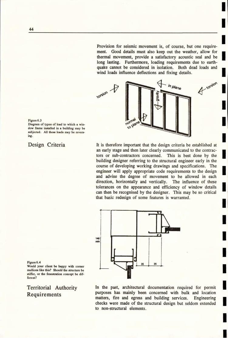
Provision for seismic movement is, of course, but one require-ment. Good details must also keep out the weather, allow forthermal movement, provide a satisfactory acoustic seal and belong lasting. Furthermore, loading requirements due to earth-quake cannot be considered in isolation. Both dead loads andwind loads influence deflections and fixing details.
torsion ----Figure 6.3Diagram of types of load to which a win-dow frame installed in a building may besubjected. All these loads may be revers-ing.
1\ ITEDesign Criteria It is therefore important that the design criteria be established at
an early stage and then later clearly communicated to the contrac-mrs or sub-contractors concerned. This is best done by thebuilding designer referring to the structural engineer early in thecourse of developing working drawings and specifications. Theengineer will apply appropriate code requirements to the designand advise the degree of movement to be allowed in eachdirection, horizontally and vertically. The influence of thesetolerances on the appearance and efficiency of window detailscan then be recognised by the designer. This may be so criticalthat basic redesign of some features is warranted.
6,
140
min
CFigure 6.4
Would your client be happy with cornermullions like this? Should the structure be
stiffer, or the fenestration concept be dif-ferent?
Territorial AuthorityRequirements
In the past, architectural documentation required for permitpurposes has mainly been concerned with bulk and locationmatters, fire and egress and building services. Engineeringchecks were made of the structural design but seldom extendedto non-structural elements.
44
f 1
1 1 35-35
In recent years concern about the design of cladding systems hasled some territorial authorities to require full details of thecladding and its attachments, either with the initial buildingpermit or as a separate permit application. Structural silicone hasalso been the source of some misgivings.
Any new building control regime, such as that envisaged in theBuilding Bill, will continue this surveillance of cladding designwhere safety is an issue.
Shop Drawings It should be noted that not all trade suppliers are themselvesequipped to prepare shop drawings that make adequate provi-sion for seismic movement, but there are consultants who special-ise in this type of work. For major building it is essential that shopdrawings be obtained and that the provision for seismic move-ment be carefully reviewed, along with other design features ofthe window systems.
Window Testing For major projects, or those incorporating special details, physi-
cal testing may be called for. A number of test facilities areavailable in New Zealand, including that of the Building Re-search Association at Judgeford, near Porirua. Racking tests cantherefore be carried out to ensure movement details will work.
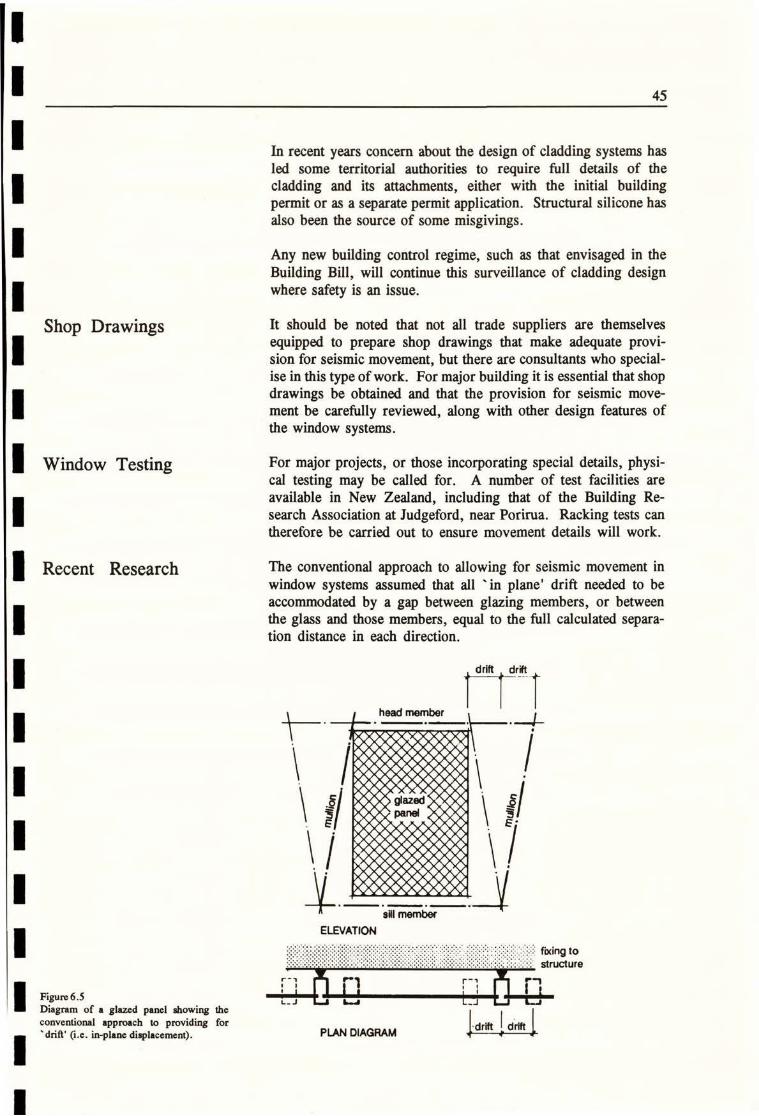
Recent Research The conventional approach to allowing for seismic movement inwindow systems assumed that all ' in plane' drift needed to beaccommodated by a gap between glazing members, or betweenthe glass and those members, equal to the full calculated separa-tion distance in each direction.
drift drift
: .i
P
51al
Ei
sill member
ELEVATK)N
fixing tostructure
r-,
L-1 LJFigure 6.5Diagram of a glazed panel showing theconventional approach to providing for ·drift 1 drift drift' 0.e. in-plane displacement). PLAN DIAGRAM 44 4
45

This is still a prudent approach in the absence of physical testingof particular systems. However, the relative lack of damage ofsome curtain walls and glazing in actual earthquakes has sug-gested that more complex movement of components, in relationto each other and the structure, can sometimes provide protec-
tion of the curtain wall and its glazing.
drift driftr ¢
head member
glazed R
Figure 6.6
Diagram showing possible movement of aglazed panel relative to its frame and the
structure. Note larger drift with the samesize panel as Figure 6.5; also flexing oftheglass as mullions are twisted. How far will
rocking and twisting go before breakage?!
ELEVATIONsill member
r-,
1 ;L-, Alr - 4--I --=*'.M===-==44
The diagram is indicative only and not to 6-.-31 danscale. PLAN DIAGRAM
The ability of glazing, in some circumstances, to withstand largerthan predicted movement without fracture is reassuring, but notguaranteed, and is dependent on many variables. Once the glassis restrained, or a corner impacts, or flexure is too great, thenfracture will occur.
This has been positively demonstrated in recent tests by theBuilding Research Association of NZ which are fully described inBRANZ Report No. SR39, " Behaviour of External GlazingSystems Under Seismic In-plane Racking" (1) It would bedangerous to generalise conclusions from this research, which ispart of an on-going programme, and includes testing of cornerassemblies.
However, two of the preliminary conclusions from this studyreport are particularly relevant:
I All the generic types of glazing systems examined duringthe study demonstrated that they were capable of acceptinginter-storey movements in excess of the maximum driftlimits defined within the current New Zealand controldocuments.
46
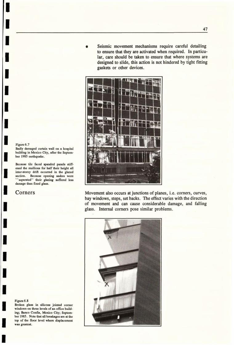
e Seismic movement mechanisms require careful detailingto ensure that they are activated when required. In particu-lar, care should be taken to ensure that where systems aredesigned to slide, this action is not hindered by tight fittinggaskets or other devices.
Figure 6.7
Badly damaged curtain wall on a hospital
building in Mexico City, after the Septem-ber 1985 earthquake.
Because tile faced spandrel panels stiff-ened the mullions for half their height all
inter-storey drift occurred in the glazedsection. Because opening sashes were' ' separated" their glazing suffered lessdamage than fixed glass.
$4 34
Corners Movement also occurs at junctions of planes, i.e. corners, curves,bay windows, steps, set backs. The effect varies with the directionof movement and can cause considerable damage, and fallingglass. Internal corners pose similar problems.
Figure 6.8
Broken glass in silicone jointed cornerwindows on three levels of an office build-
ing; Banco Confia, Mexico City; Septem-ber 1985. Note that all breakages are atthetop of the floor level where displacementwas greatest.
1
X
I Rit...:;f:
47

,1
gap
opens bre
Washingdamagedat least)
glassbreaks
J
gap
opens. i bre
\U
5S
aks
IS
aks
warping0- of panels
// /5
movement at
head of glazing
torsional movement
Figure 6.9
Typical diagrams of corner windows sub-ject to deflection in an earthquake.
Source: Drawing based on diagrams byE.B. Lapish.
at head of glazing
48

Allowing for Movement:
Four Approaches
Four generic approaches are shown but it is possible for differentmethods to be used in one glazing system or in one building.
TT-T
7777777773-
:29-2415551
11 =n.
Figure 6.10Seismic frame.
The glazed frame moves in a seismic frame,which moves with the building. The glazingframe is usually fixed at the sill.
jELEVATION DIAGRAM PLAN DETAIL
Figure 6.11Glazing pocket.
The glass is usually gasket glazed directinto the frame with pockets' around theglass sufficiently deep to admit movement.This is a common approach in ' stick' sys-terns.
X >
ELEVATION DIAGRAM
-Et
PLAN DETAIL
1_ LL
.
...
11
Figure 6.12Unitised system.
Individual units interlock, with provisionfor movement between each unit, both
horizontally and vertically. This approachhas become very common in multi-storeywork especially. Structural silicone is oftenused for fixing glass in unitised systems, butin this case the silicone itsel f is not requiredto accept deOections. PLAN DETAILELEVATION DIAGRAM
49
. Z Nu
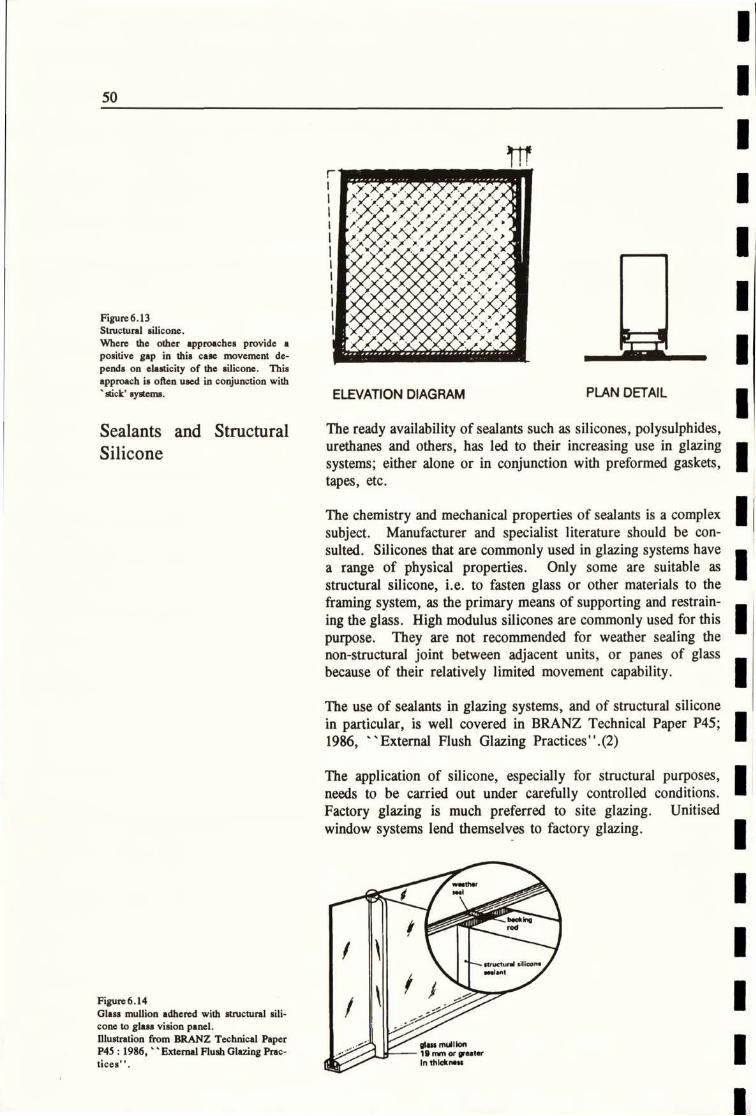
Figure 6.13Structural silicone.
Where the other approaches provide apositive gap in this case movement de-
pends on clasticity of the silicone. This
approach is often used in conjunction with stick' sy*ems.
XX
A
ELEVATION DIAGRAM PLAN DETAIL
Sealants and Structural
Silicone
The ready availability of sealants such as silicones, polysulphides,urethanes and others, has led to their increasing use in glazingsystems; either alone or in conjunction with preformed gaskets,tapes, etc.
The chemistry and mechanical properties of sealants is a complexsubject. Manufacturer and specialist literature should be con-sulted. Silicones that are commonly used in glazing systems havea range of physical properties. Only some are suitable asstructural silicone, i.e. to fasten glass or other materials to theframing system, as the primary means of supporting and restrain-ing the glass. High modulus silicones are commonly used for thispurpose. They are not recommended for weather sealing thenon-structural joint between adjacent units, or panes of glassbecause of their relatively limited movement capability.
The use of sealants in glazing systems, and of structural siliconein particular, is well covered in BRANZ Technical Paper P45;1986, "External Flush Glazing Practices". (2)
The application of silicone, especially for structural purposes,needs to be carried out under carefully controlled conditions.Factory glazing is much preferred to site glazing. Unitisedwindow systems lend themselves to factory glazing.
--- ructur,1 silicon• /
Figure 6.14Glass mullion adhered with structural sili- 0 / /19cone to glass vision panel. //5/Illustration from BRANZ Technical Paper //
glms mullionP45 : 1986, -External Flush Glazing Prac- -;>13<1--zo 19 mm or greatertices". In thlckn-
50
r-
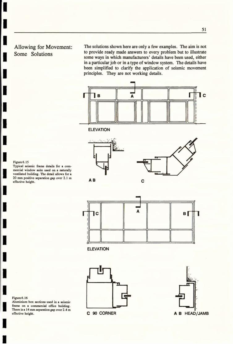
Allowing for Movement:Some Solutions
The solutions shown here are only a few examples. The aim is notto provide ready made answers to every problem but to illustratesome ways in which manufacturers' details have been used, eitherin a particular job or in a type of window system. The details havebeen simplified to clarify the application of seismic movementprinciples. They are not working details.
El B -bcA
ELEVATION
Figure 6.15
Typical seismic frame details for a com-
mercial window suite used on a naturally
ventilated building. The detail allows for a20 mm positive separation gap over 2.1 meffective height.
'15.
-11_AB C
r c A B 1-1
ELEVATION
a-i
Figure 6.16Aluminium box sections used in a seismic
frame on a commercial office building.There is a 14 mm separation gap over 2.4 meffective height.
r
C 90 CORNER A B HEAD/JAMB
51
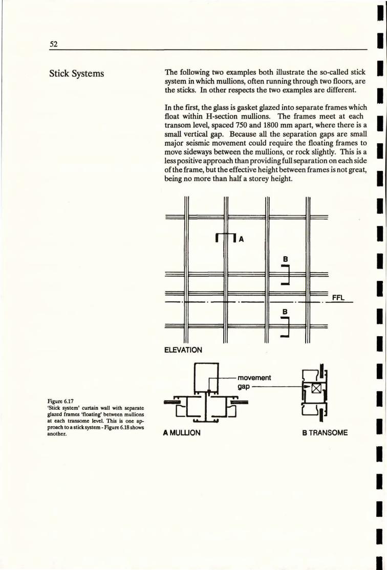
Stick Systems The following two examples both illustrate the so-called sticksystem in which mullions, often running through two floors, arethe sticks. In other respects the two examples are different.
In the first, the glass is gasket glazed into separate frames whichfloat within H-section mullions. The frames meet at each
transom level, spaced 750 and 1800 mm apart, where there is asmall vertical gap. Because all the separation gaps are smallmajor seismic movement could require the floating frames tomove sideways between the mullions, or rock slightly. This is aless positive approach than providing full separation on each sideof the frame, but the effective height between frames is not great,being no more than half a storey height.
Fl A
B
FFL
1 11 k
ELEVATION
movement
Figure 6.17'Stick system' curtain wall with separateglazed frames 'floating' between mullionsat each transome level. This is one ap-proach to a sticksystem - Figure 6.18 showsanother.
Eli:gap
63,1-iL -A MULLION B TRANSOME
52
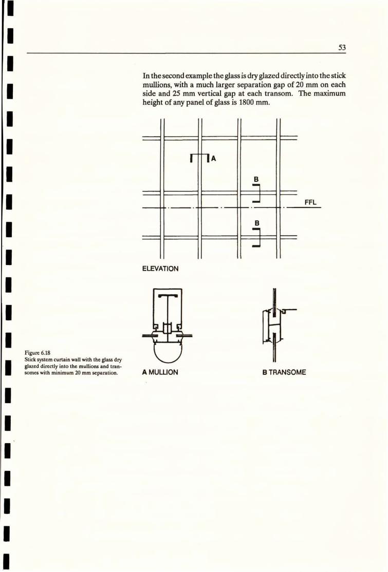
In the second example the glassis dry glazed directlyinto the stickmullions, with a much larger separation gap of 20 mm on eachside and 25 mm vertical gap at each transom. The maximumheight of any panel of glass is 1800 mm.
|1 A
FFL
B
ELEVATION
Figure 6.18
Stick system curtain wall with the glass dryglazed directly into the mullions and tran-somes with minimum 20 mm separation. A MULLION B TRANSOME
53

Unitised Systems Two examples are shown: In both cases the same principlesapply, although one building is a four storey speculative officeblock and the other a prestige double-glazed high-rise tower foran institutional client.
In both cases the individual units are storey height and factoryglazed, using structural silicone. The framing members (mul-lions, transomes) which appear to be single sections are in factcomprised of two interlocking parts, each forming the side of aunit. Movement can thus occur between units. In both cases
mullion divisions are not expressed on the exterior.
1
F7A F-18
FFL
Figure 6.19
A unitised curtain wall system applied to a
small office building. Structural siliconesingle glazing is used. An applied cappingexpresses the transome lines.
11 1 1
ELEVATION
--'gl
A MULLION
..
k
==.1B JAMB
r
54
.... L-

In this example (on a high rise tower) each unit is 3.6 metres highby 1.2 metres wide. A test assembly including a corner windowwas made up and subjected to a racking test to simulate earth-quake loading. No failure of the system occurred.
FFL
double
glazing
Figure 6.20
A unitised system incorporating doubleglazed units and granite spandrel panels.Whilst structural silicone is used a me-
chanical retaining angle is also provided attransomes.
FFL
granite--1
ELEVATION
B
rr-11T-T-
A MULUON B TRANSOME
granlte/glazingas applicable
55

Special Cases Three entirely different examples illustrate the range of complexsituations that may arise:
Case 1
Figure 6.21Detailsof the Studio windowsin the School
of Architecture, Auckland University.
Each frame is nearly 7 metres square and
made from welded steel, capped byalumin-
ium glazing extrusions. The frame is stiff-ened by exposed bracing. Seismic move-
ment is accommodated by using an en- B flarged purpose-made seismic frame.
A
-1
L-j
E Il
C
6.750
1
L
ELEVATION
LT
C
B JAMB
U- L
0
C SEISMIC SEPARATION
AT 45*CORNER
56
A HEAD

Case 2
Figure 6.22
The main glazing for Aucklandk AoteaCentre required 10 mm thick toughened
glass to bc uscd in window panels sized upto 6 metres x 2 metres. Stiffened millions
were required, with provision for seismicmovement. Manufacturing restrictionsalso meant that horizontal silicone jointswere required in the tall glass.
seismic - seismic -head shoe
HEAD DETAILA
Where the glazing turns through 45 and90 special details were developed at thecomets using a tube mullions and H-sec-
tion transomes. The detail supports the
glazing under gravity, wind and impact
loads but will accommodate interstoreydrift in an earthquake.
T A 6+-,11j
6.100
76 O.D
tube
-25 O.D
tubes
1,1--47#
ELEVATION SECTION
-760.0 pipe
-250.D spacers
PLAN
seismic
* drift
CORNER DETAIL
57
2.000
r
TYPICAL
MULUON

Case 3 -..7
Figure 6.23These details were developed by CLC
Consulting Group asa means of accommo-dating seismic movement in the curvedcorners of a multi-storey building. Onlypart of the detailing is shown. Such com-plex situations requiring clear thinkingabout both design and construction issues.
[Redrawn with permission from details byE.B. Lapish of CLC Consulting Group]
1
T
Wall at right angles toearthquake directionmoves with building
- Steel support towindow head to
resist wind loads
Ductile bracket motivated
by seismic forces in glazingsystem allows for movement relative to curved comer glaz 1
1/
29
mi
0
id-49
Weather sealat seismic gap
1
1
VERTICAL SECTION
11 1Iti Ir-1
separation 30mm Seismic
nashing
HORIZONTAL SECTION
58
1

All-glass Assemblies Whilst silicone glazing systems have been touched on earlier inthis section, nothing has so far been said about "all glass" assem-blies, which have become increasingly common, especially forenclosing foyers of large office buildings and in atria etc. Theseassemblies can behungfromspecially designed steelframing, theindividual glasspanes being stiffened by toughened glass fins andjoined by proprietary stainless steel bolted connectors.
In principle such an assembly is a glass curtain which is not fixedat floor level and to that extent seismic movement is not difficult
to accommodate. In detail such assemblies are special designexercises requiring early input from both the project structuralengineer and a structural glazing specialist.
Glass Blocks Glass blocks are again popular and two recent BRANZ Bulletins(Nos 281 and 282) address selection, design and installationtopics (3). Bulletin 281 includes comments (on page 3) that:
Mortared block walls should be separated at the top and sidesfrom the surrounding structure by a cushion material whichprotects the glass block wall from the effects of expansion,interstorey drift and building movement.
It is also noted that:
The wall into which the glass blocks are inserted must bedesigned and constructed to prevent structural loads from thebuilding being transmitted to the glass blocks.
Both comments relate to earthquake movement.
(1) Building Research Association of New Zealand: Behaviour of External GlazingSystems under Seismic In-plane Racking, Lim, KY.S. and King, A.B., Februaty 1991.
(2) Bennett, A.F.: External Flush Glazing Practices, BRANZ Technical paperp.45,1986.
(3) BRANZ Bulletin No. 281, August 1991, Glass Blocks Selection and DesignBRANZ Bulletin No 282, August 1991, Glass Blocks Materials & Installation
59

Internal Elements
General Commentary In the context of this handbook internal elements are part ofthe interior of a building but are not designed to be part of itsprimary load bearing structure. For example, a shear wallis partof the structural design, but other concrete or masonry walls maybe needed for fire ratingpurposes, or to provide acoustic separa-tion. These walls may not be intended to affect the response ofthe structure in an earthquake.
Therefore any internal non-structural element that is rigid, or sostiff that it may alter the seismic performance of the building,should be separated from the structural elements.
Figure 7.1Internal plastered brick partitions sufferedextensive damage in Mexico City, Septem-ber 1985. Usually no separation was pro-vided. L
The design engineer should be made aware of such elements,whether they are part of the original design or later additions; forinstance anew concrete block firewallinstalled aspart ofbuildingrefurbishment. It is important that such an additional wallis notbuilt tightly between columns in (say) a factory conversion,without an engineering check being made.
Reference can be made to Section 3 of this handbook for a
summary of NZ code requirements.
61
7

Rigid Partitions(other than shear orbracing walls)
Rigid partitions have negligible in-plane flexibility. They in-clude concrete and masonry walls and panels, but can also beframed walls lined with continuous sheathing such as ply orsecurely fixed plasterboard, particularly if such partitions areextensive or are located where they can affect the structuralperformance of the building.
Further comments are given in Section 8.
Lightweight Partitions Lightweight partitions that are not specially designed havelimited bracing capability. They often finish at ceiling level andmay either affect or be subject to the movements of the ceilingsystem.
Further comments are in Section 8.
Ceilings Lightweight suspended ceilings are likely to be affected in anearthquake. They may support building services, such as lightsand air conditioning outlets. Collapse can impede evacuationand might cause casualties.
Further comments are in Section 8.
Figure 7.2
Ceiling collapse in the Pino Suarez MetroStation, Mexico City, September 1985.
Stairs Unless stairwell partitions are designed to provide shear resis-tance, the stair flights and their enclosing partitions are usuallynon-structural. If separation joints are required in the stairenclosure then details must be devised that maintain fire ratings.Figure 7.3 shows one such situation.
Stair flights themselves, unless of lightweight construction, willprobably require seismic separation at one end. This can alsoapply to open stairs to say a mezzanine. The separation detailnormally takes the form ofa simple slidingjoint. Specialarrange-ments may be needed to ensure clean and usable floor finishes atthese locations. See figure 7.4.
62

.- -fire rated partitions
DUCT STAIRWAY
Figure 7.3
When separation details are required inpartitions enclosing stairways fire ratingsmust be maintained.
1. flexible fire stoppingin separation
FL(
' SLe
'5
pressedstainless steel
vinyl -7 cover plate -1-
71.Ati
concrete flight71 -flexible filler if in-situ
Figure 7.4
Separation of a stair flight at the landing. Ifa filler is used it must be flexible (or be re-moved after the slab is poured). Reinforc-ing omitted in this illustration.
4•
steel plate for -separation
Building Services Building services plant and its supports need to be restrainedagainst seismic movement to prevent damage and failure of theservices. As large forces can be involved, specific structuraldesign is often necessary. This is provided by either the buildingdesigner or the plant supplier.
63

Pipes, ductwork and wiring are usually adequately fixed, at leastto resist gravity loads, but clearances from partitions etc. may beneeded.
Building services fittings, such as lights, air conditioning units andheaters need support and restraint. Heavy fittings above or in theceiling system must be suspended directly from the structurerather than supported by the ceiling.
Figure 7.5This gas tank rolled off its support duringthe Mexico City earthquake.
Fittings Fittings are items of furniture built into or fixed to the building.Usually no allowance for seismic movement is required andstandard fixings are often satisfactory, but special attention isneeded for tall or heavy items.
Furniture Furniture items are not attached to the building. While mostfurniture does not need special fixings, items such as shelving,computer equipment, filing cabinets, and the like, should bechecked to ensure their stability in an earthquake. Research onthis and related topics has been described by A.W. Charleson. (1)
-cabinet wall
steel anglcbracket
bolted
connectors
base reinforcingFigure 7.6Bolt on fixing of a freestanding cabinet.[Redrawn from 'Earthquake Protection ofChanels and Light (*ce Equipmene byA.W. Charleson (1)1
member may be required
£18. -73
64

r
- 2/65 x 65 x 1.8 steel brackets
r screws
1
wood screws into
studs or a Ramset
716217 spring toggleor equivalent
1)
BOOKCASE/CABINET DETAIL
FROM END ON
Figure 7.7Restraint to top ofstorageunit against wall{Source as Fig. 7.61
--4\,
112,<..,rvy Television
974 Monitor
4
Ramset 716033 gravity toggle or equivalent(or 2/40mm eye screws into studs)
Ramset 719119 metal hook (crimped)
1I brass plated wire (or 30kg nylon)
1 02mm snaplink-34mm swivel
1
gib. board
Figure 7.8Restraint of a TV monitor on a high level shelf.[Source as Fig. 7.6]
1
Library Shelves Library shelf units present a particular risk and should be fixed orsupported so that they do not fall over in an earthquake. They canbe braced one to another and to the building structure.
65
1

Storage Shelves Shelves, racks and bins in offices and warehouses often need
special restraint. They can be of considerable height, and supporta substantial weight. This is easily overlooked.
Extensive shelving is often arranged as a separate or latercontract. In this case it should be brought to the attention of thebuilding designers that such items will be installed so that theeffect of this loading can be taken into account.
3.:::: t.1.+0 i '*3 27"2 12,9. -6* ©447 " :KN >
R: -624*
¥ 1
Figure 7.9Note the height of these storage units in an |Auckland warehouse and their substantial
loading. Clearly stability in an earthquake
is in question.
-5981;G,@i- ./011:9.4.' 1.0,>k
Raised Floors Offices may include proprietary raised floors to allow access tobuilding services. Such floors require restraint and allowance formovement at perimeters and around fixed items. The suppliersof proprietary types should provide seismic details.
Figure 7.10Pedestals supporting 600 mm x 600 mm
floor panels (Cemac Access Floor systemillustration)
(1) Charleson, A.W., School of Architecture, Victoria University of Wellington:
"Earthquake Protection of Chattels and Light Office Equipment". Report to the NZ
National Society for Earthquake Engineering, February 1989.

Partitions - Specifically
Rigid and lightweight partitions have been described briefly inSection 7.
Rigid Partitions Rigid partitions, especially those of concrete or masonry con-struction can seriously affect the seismic performance of thebuilding and therefore need to be separated from the buildingstructure.
NZS 4203 also requires that rigid partitions be anchored top andbottom, where this is required to provide lateral support orstability. To avoid stiffening the structure, the anchors must beable to accommodate both in-plane and vertical movement.
Separation details are usually designed to allow differentialmovement between partitions and structure in the plane of thewall. Movement normal to the wallis accommodated by allowingthe partition to sway with the structure when deflections occurunder seismic loading.
/t. ... 4 t.
I ....11.
17---r--flexible sealant----4-galvanised steel- ----,1
L-- 1 strap flexible in*1 plane of the wall f .42·· ' ': .'. >
1 41 :1.,
1,4...4.7.1,1, 7*-4-- reinforcing steel
.· 1
0 1 LD.
...
Figure 8.1
Separation detail at the head of a rein-forced concrete blockpartition not requir-ing a fire rating to be maintained.
In principle this is very simple, but in practice a variety of morecomplex situations arise. No general solution is available buteach case can be approached from first principles in a logicalmanner to arrive at a cost effective solution. Some examples ofdetails that have been used are shown.
For the architectural designer the need to provide seismic sepa-ration is often in conflict with the day-to-day requirement tomaintain acoustic privacy and fire ratings. A further concern isto provide details that will require little reinstatement after anearthquake, particularly more frequent smaller seismic events.
67
8
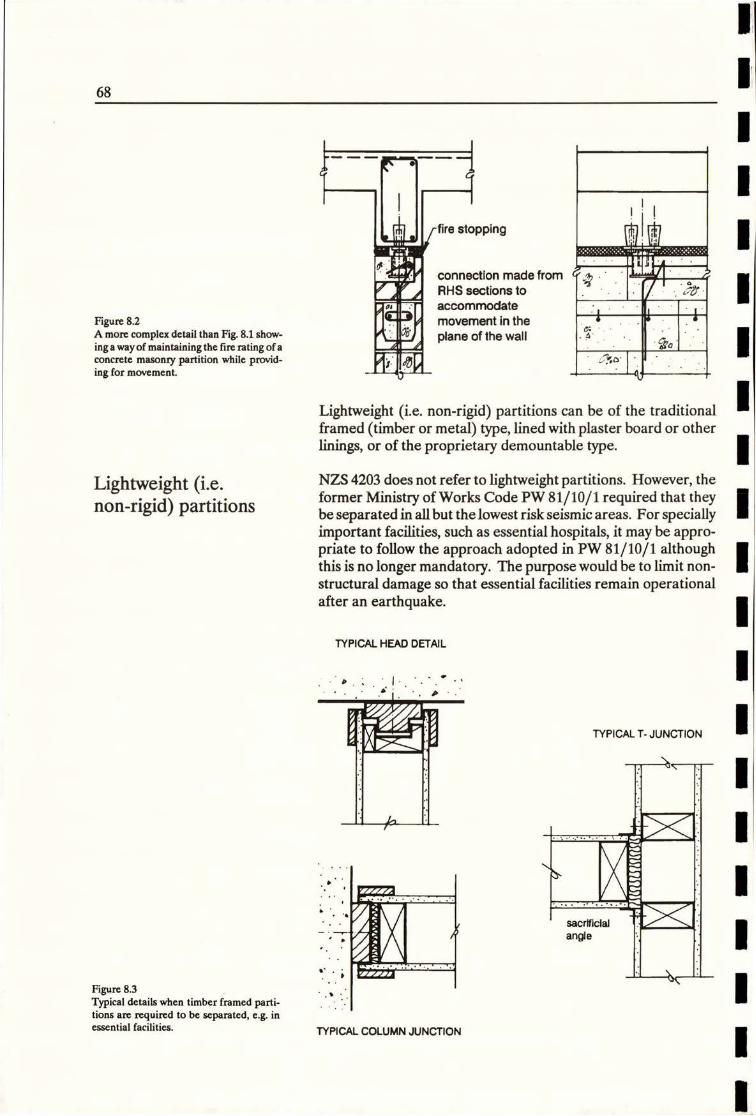
'i
Figure 8.2
A more complex detail than Fig. 8.1 show-ing a wayof maintaining the fire rating of aconcrete masonry partition while provid-ing for movement.
fire stopping
connection made from
RHS sections to
accommodate
movement in the
plane of the wall
bJ. 1 .0
1
Lightweight (i.e. non-rigid) partitions can be of the traditionalframed (timber or metal) type, lined with plaster board or otherlinings, or of the proprietary demountable type.
Lightweight (i.e.non-rigid) partitions
NZS 4203 does not refer to lightweight partitions. However, theformer Ministry of Works Code PW 81/10/1 required that theybe separated in all but the lowest risk seismic areas. For speciallyimportant facilities, such as essential hospitals, it may be appro-priate to follow the approach adopted in PW 81/10/1 althoughthis is no longer mandatory. The purpose would be to limit non-structural damage so that essential facilities remain operationalafter an earthquake.
TYPICAL HEAD DETAIL
.
TYPICAL T- JUNCTION
\,
sacrificlal 11/ \1angle
Figure 8.3
Typical details when timber framed parti-tions are required to be separated, e.g. inessential facilities. TYPICAL COLUMN JUNCTION
68
1
f1

-bulkhead framed downfrom structure
ceiling level
angle shorts
SEISMIC DETAIL ATBULKHEAD
Figure 8.4Further examples of separation of timber
framed partitions.
JUNCTION NEAR
DOOR FRAME
Lightweight partitions have some flexibility, but this will vary withthe materials and details. Most traditionally framed and linedpartitions can be considered lightweight, in a structural sense, butfire ratings may require thicker linings and closer finishes to thestructure. Such partitions may initially stiffen the structure butwill ' soften up' when subjected to successive cycles of seismicmovement, as fixings work and linings are crushed at edges. Thiscan be a bad situation in a major earthquake, leading to greaterdamage, unless separation details are provided that allow formovement whilst also maintaining fire ratings.
i 11
...1 P..t
3.0
bulkhead ·-U
0099
Figure 8.5
A more complex detail with fire rated par-titions.
l
le!
69
9

Proprietary partitions normally have metal studs that are afriction fit in the top and bottom members. Caps are allowed atthe head of studs, and there is thus some inherent flexibility in thepartition system. These are commonly two types:
(a) "Demountable", where the linings are screw fixed andjoints butted or covered with clipped cover strips. This type ofpartition has inherent flexibility.
(b) Flush lined, where joints in the linings are stopped flush.This type will have less overall flexibility.
Bulldog
32mm hole
punched insteel channel
10mm
+ t
40mm 6
KAOWOOD,17.1packing : :' · · 0:.4
purpose madecups ex 1.6rnm(16g) galvd.mild steel
concrete - compression springpenetration
by 25.4mm _70 x 35 x 1 mmBulldog steel channel
Figure 8.6
A seismic head detail for a proprietaryretaining washer 50 x 80mm -68.5 x 35 x 9.5mm
walling system Crrend Waiting Systems bolt stud
Limited).
In practice, lightweight proprietary partitions are usually fixed toceilings, unless specified otherwise, and this is commonly consid-ered acceptable except in essential facilities where separationshould be considered.
In a lightweight partition system (of any type) it is recognised thatcorners and junctions are particularly liable to seismic damageunless partitions are either freestanding or detailed to provideseparation and movement.
Glazed Partitions Allowance for movement in glazed partitions may also needconsideration.
Smaller areas of glass, gasket glazed into metal or timber sec-tions, are generally acceptable. However, adequate gaps shouldbe provided between the sections/fixings and the glass to preventcontact and damage.
Where large areas of glass are used, particularly when sheets ofglass are butt joined with silicone, special allowances for move-ment may be required.
70

r
9
Suspended Ceilings
The risk arising from suspended ceilings being damaged in anearthquake has already been noted. Lighting and buildingservices can also be affected if connected to, or supported by, theceiling system.
Light fittings and other items weighing over 25 kg should be sus-pended directly from the building structure or be otherwisesupported independent of the ceiling system.
BRACED CEILING
In New Zealand, the seismic design of ceilings is covered by NZS4203, the Loadings Code (Refer Section 3 of this handbook). The
former Ministry of Works Codes PW 81/10/1 and Code ofPractice for Structural Design of Suspended Ceilings may also beapplied in some cases.
r Lateral ceiling loads can be resisted by transferring loads to
perimeter walls or structure, or by bracing from the structureabove. Movement joints may be needed at the perimeter, andrunners may need restraint to prevent them buckling upwards.
LATERAL SUPPORT
OF ADJACENT WALLS
1 -1-
14 4SUPPORTED OFF
PARTITIONSFigure 9.1
Three principles of support of suspended
Ceiungs.
Tiles should be clipped in place to prevent them being dislodged,and to retain their diaphragm action. However, a recent surveyhas identified that few recent commercial buildings observe thisrequirement. The subject requires further research and develop-ment to provide cost effective clipping, both at the time of theinitial installation and later on, when maintenance access toservices, etc. is required.
Rigid items that pierce the ceiling, such as sprinklers, can causedamage to the ceiling installation and allowance for movementshould be made around such items.
The major suppliers of proprietary ceilings have developed de-tails to provide for bracing and movement in compliance with theappropriate codes. Their technical staff should be consulted atan early stage of the design if there are any special requirements.
71
1
1
1
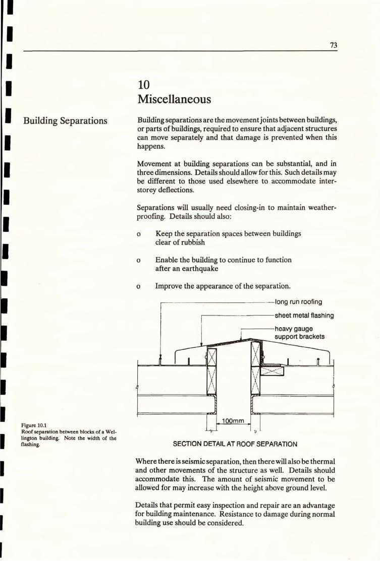
Miscellaneous
Building Separations Building separations are the movement joints between buildings,or parts of buildings, required to ensure that adjacent structurescan move separately and that damage is prevented when thishappens.
Movement at building separations can be substantial, and inthree dimensions. Details should allow for this. Such details maybe different to those used elsewhere to accommodate inter-
storey deflections.
Separations will usually need closing-in to maintain weather-proofing. Details should also:
o Keep the separation spaces between buildingsclear of rubbish
o Enable the building to continue to functionafter an earthquake
o Improve the appearance of the separation.
long run roofing
sheet metal flashing
heavy gaugesupport brackets
11
g
Figure 10.1Roof separation between blocks of a Wet-lington building. Note the width of theflashing.
I , 100mm _ LUV
SECTION DETAIL AT ROOF SEPARATION
Where there is seismic separation, then there will also be thermaland other movements of the structure as well. Details should
accommodate this. The amount of seismic movement to be
allowed for may increase with the height above ground level.
Details that permit easy inspection and repair are an advantagefor building maintenance. Resistance to damage during normalbuilding use should be considered.
----
73
10
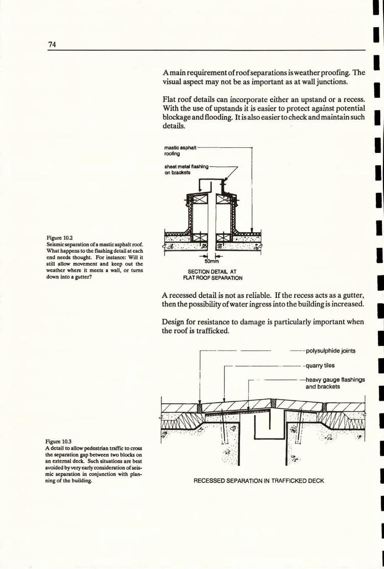
Amain requirement ofroofseparations isweatherproofing. Thevisual aspect may not be as important as at wall junctions.
Flat roof details can incorporate either an upstand or a recess.With the use of upstands it is easier to protect against potential
blockage and flooding. Itis also easierto check and maintain such details.
masuc asphan
roofing
Figure 10.2
Seismic separation ofa mastic asphalt roof.What happens to the flashing detail at eachend needs thought. For instance: Will itstill allow movement and keep out theweather where it meets a wall, or turns
sheet metal flashingon brackets
50mm
SECTION DETAIL AT
down into a gutter? FLAT ROOF SEPARATION A recessed detailis not as reliable. If the recess acts as a gutter,then the possibility of water ingress into the building is increased.
Design for resistance to damage is particularly important when the roof is trafficked.
- - polysulphide joints
-quarry tiles
_-neavy gauge Ilatillirli;3
and brackets
- Ij l 11
1 1 ......1
1 1
Figure 10.3
A detail to allow pedestrian traffic to crossthe separation gap between two blocks onan external deck. Such situations are best
avoided byvery early consideration of seis-mic separation in conjunction with plan-ning of the building.
1 -
1-7.-1 - : LU
..
RECESSED SEPARATION IN TRAFFICKED DECK
1
74
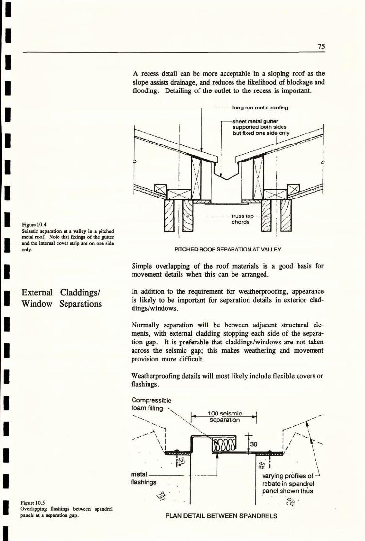
A recess detail can be more acceptable in a sloping roof as theslope assists drainage, and reduces the likelihood of blockage andflooding. Detailing of the outlet to the recess is important.
-long run metal roofing
-sheet metal gutter
supported both sidesbut fixed one side only
»Chkf\\
0
/ 771,
-· -----truss top--*•tFigure 10.4Seismic separation at a valley in a pitchedmetal roof. Note that fixings of the gutterand the internal cover strip are on one side
only.
chords 5,5 1/./
PITCHED ROOF SEPARATION AT VALLEY
Simple overlapping of the roof materials is a good basis formovement details when this can be arranged.
External Claddings/ In addition to the requirement for weatherproofing, appearanceis likely to be important for separation details in exterior clad-Window Separationsdings/windows.
Normally separation will be between adjacent structural ele-ments, with external cladding stopping each side of the separa-tion gap. It is preferable that claddings/windows are not takenacross the seismic gap; this makes weathering and movementprovision more difficult.
Weatherproofing details will most likely include flexible covers orflashings.
Compressible
foam filling - 100 seismic .*/
- separation
metal
flashIngsvarying profiles of -1rebate in spandrelpanel shown th6s
Figure 10.5 .1 . 0:Overlapping flashings between spandrelpanels at a separation gap. PLAN DETAIL BETWEEN SPANDRELS
75
1
\130
\1

f.-
./0.
a
1
E1
heavy gaugeflashing
- mastic asphalt
-timber deck
beam in
metal shoe
- bolt throughslottedconnection
Figure 10.6
Each type of separation requires individualattention. SEPARATION AT WALL TO FLAT ROOF JUNCTION
Internal Element
Separations
To allow for expected movement details are better provided atthe separation space, rather than close to it.
light metalangle
- flexible vinyl* cover pop-rivetted
+ 0 11 17
Figure 10.7
Internal separation details at a seismic gapcan usually be quite simple.
. 1
CEILING TO WALL JUNCTION
76
1
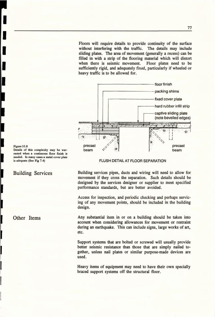
Floors will require details to provide continuity of the surfacewithout interfering with the traffic. The details may includesliding plates. The area of movement (generally a recess) can befilled in with a strip of the flooring material which will distortwhen there is seismic movement. Floor plates need to besufficiently rigid, and adequately fixed, particularly if wheeled orheavy traffic is to be allowed for.
floor finish
packing shims
fixed cover plate
hard rubber infill strip
- captive sliding plate(note bevelled edges)
.
'12 3 j A F f .. , . PM.feV/7'8
Figure 10.8Details of this complexity may be war-ranted when a continuous floor finish is
needed. In many cases a metal cover plateis adequate (See Fig 7.4)
precastbeam ep
4o
precastbeam
FLUSH DETAIL AT FLOOR SEPARATION
Building Services Building services pipes, ducts and wiring will need to allow for
movement if they cross the separation. Such details should bedesigned by the services designer or supplier to meet specifiedperformance standards, but are better avoided.
Access for inspection, and periodic checking and perhaps servic-ing of any movement points, should be included in the buildingdesign.
Other Itenns Any substantial item in or on a building should be taken intoaccount when considering allowances for movement or restraintduring an earthquake. This can include signs, large works of art,etc.
Support systems that are bolted or screwed will usually providebetter seismic resistance than those that are simply nailed to-gether, unless nail plates or similar purpose-made devices areused.
Heavy items of equipment may need to have their own speciallybraced support systems off the structural floor.
- -=-0 --

Bibliography
Allen D: 'The La Palle Tie Connector", 8th International Brick/Block MasonryConference, Dublin, Ireland, September 1988
Amen P, Jessop EL: "Masonry Cladding, a Report on Causes and Effects ofFailure",Centre ofResearch andDevelopment inMasonry,Calgary,Canada 1984
Arnold C: "Architectural Configuration and Seismic Performance in Vina delMar, Chile", Building Systems Development Inc, September 1990
Arnold C: "Clad(ling Design, Recent Architectural Trends and Their Impact onSeismicDesign", Proceedings, "Architecturalprecast cladding-its contribution tolateral resistance of buildings", Chicago, November 1990
Arnold C, Hopkins D and Elsesser E: "Design and Detailing of ArchitecturalElements for Seismic Damage Control", Building Systems Development Inc.;KRTA Limited and Forell/Elsesser Engineer Inc, March 1987
Arnold C and Reitherman R: "Building Configuration and Seismic Design", John
Wiley 6· Sons, New York, 1982
Bennett AF: "External Flush Glazing Practices", BRANZ Technical Paper, 1986
Bolt BA: "Earthquakes, a Primer", (C) WH Freeman and Company, New York,1978
BRANZ Bulletin No 281. "Glass Blocks Selection and Design", August 1991
BRANZ Bulletin No 282. "Glass Blocks Materials and Installation", August 1991
Charleson AW, School of Architecture, Victoria University of Wellington:
"Earthquake Protection of Chattels and Light Office Equipment", Report to theNZ National Society for Earthquake Engineering, February 1989
HopkinsDC,Massey WE and Pollard JL:"ArchitecturatElementsin Earthquake,A Review ofDesign and Construction Practice In New Zealand", Bull NZNSEE,Vol 18 No 1, March 1985
Lagorio HT: "Earthquakes - an architect's guide to non-structural seismk hazards,"John Wiley & Sons Inc, New York 1990
Lapish EB and Allen D: "Variability of Tie Loads in Brick Masonry Veneer
Construction", Proceedings of 4th Canadian Masonry Symposium, Fredriston,Canada, 1986
LapishEB: "AseismicDesign ofBrick VeneerCladding", 8thInternational Brick/Block Masonry Conference, Dublin, Ireland, September 1988
Lapish EB: "Aseismic Designs of Brick Veneer and the NZ Building Codes",Pacific Conference on Earthquake Engineering, Auckland, New Zealand, No-vember 1991
Lim KYS and King AB: "Behaviour of External Glazing Systems under SeismicIn-plane Racking", BRANZ Report, February 1991
McGinley WM, LongworthJ, WarwarukJ and HatzinikolasM: "MasonryVeneerand Steel StudCurtain Walls", Proceedings of 4thCanadianMasonrySymposium,Fredriston, Canada, 1986
79
1
80
Ministry of Works and Development, New Zealand: "Code of Practice, Seismic Design of Public Buildings", Office of the Chief Structural Engineer, PW 81/10/1,1976
Reitherman R: "Reducing the Risks of Non-structural Earthquake Damage: APractical Guide", Bay Area Regional Preparedness Project (BAREPP), 1985
Rihal SS: "Earthquake Resistance and Behaviour of Architectural Precast Clad- ding and Connections", Proceedings, "Architectural precast cladding - its contri-bution to lateral resistance of buildings", Chicago, November 1989
NZS 4219: "Specification for Seismic Resistance of Engineering Systems inBuildings", Standards Association of New Zealand, 1983
NZS 4203: "Code of Practice for General Structural Design and Design Loadings for Buildings", Standards Association of New Zealand, 1984
Smith WD: "Earthquake Hazard in New Zealand, Some Implications of theEdgecumbe Eartquake, March 1987", Bull NZNSEE, Vol 23, No 3, September 1990
Stevens G: "Lands in Collision, Discovering New Zealand's Past Geography", SIPC, Wellington, New Zealand, 1985
1
1
1
1
1
1
1
1

1
1
1
1
1
1
1
I
1
1
1
1
1
1
1
1
1
1 -7/01

f]
j
flL
0-17