Embed Size (px)
Citation preview
(2½ Hours)
[Total Marks: 75
N. B.: (1) All questions are compulsory.
(2) Make suitable assumptions wherever necessary and state the assumptions made.
(3) Answers to the same question must be written together.
(4) Numbers to the right indicate marks.
(5) Draw neat labelled diagrams wherever necessary.
(6) Use of Non-programmable calculators is allowed.
1 Attempt any three of the following: 15
a. State and explain various types of networks. What are the different ways to access the
Internet?
Ans Types of network
1) LAN: A local area network (LAN) is usually privately owned and connects some hosts
in a single office, building, or campus. Depending on the needs of an organization, a
LAN can be as simple as two PCs and a printer in someone’s home office, or it can
extend throughout a company and include audio and video devices. Each host in a
LAN has an identifier, an address that uniquely defines the host in the LAN. A packet
sent by a host to another host carries both the source host’s and the destination host’s
addresses
2) WAN: A wide area network (WAN) is also an interconnection of devices capable of
communication. However, there are some differences between a LAN and a WAN. A
LAN is normally limited in size, spanning an office, a building, or a campus; a WAN
has a wider geographical span, spanning a town, a state, a country, or even the world.
A LAN interconnects hosts; a WAN interconnects connecting devices such as
switches, routers, or modems. A LAN is normally privately owned by the organization
that uses it; a WAN is normally created and run by communication companies and
leased by an organization that uses it. We see two distinct examples of WANs today:
point-to-point WANs and switched WANs.
Different ways to access the Internet are:
1) Using Telephone Networks Today most residences and small businesses have
telephone service, which means they are connected to a telephone network. Since most
telephone networks have already connected themselves to the Internet, one option for
residences and small businesses to connect to the Internet is to change the voice line
between the residence or business and the telephone center to a point-to-point WAN.
This can be done in two ways.
A) Dial up service B)DSL Service
2) Using Cable Networks
More and more residents over the last two decades have begun using cable TV
services instead of antennas to receive TV broadcasting. The cable companies have
been upgrading their cable networks and connecting to the Internet. A residence or
a small business can be connected to the Internet by using this service
3) Using Wireless Networks
Wireless connectivity has recently become increasingly popular. A household or a
small business can use a combination of wireless and wired connections to access
the Internet
4) Direct Connection to the Internet
A large organization or a large corporation can itself become a local ISP and be
connected to the Internet. This can be done if the organization or the corporation
leases a high-speed WAN from a carrier provider and connects itself to a regional
ISP
b. What is Internet standard? Explain the maturity levels of RFC.
Ans An Internet standard is a thoroughly tested specification that is useful to and adhered to by
those who work with the Internet. It is a formalized regulation that must be followed.
There is a strict procedure by which a specification attains Internet standard status. A
specification begins as an Internet draft. An Internet draft is a working document (a work
in progress) with no official status and a six-month lifetime. Upon recommendation from
the Internet authorities, a draft may be published as a Request for Comment (RFC). Each
RFC is edited, assigned a number, and made available to all interested parties. RFCs go
through maturity levels and are categorized according to their requirement level.
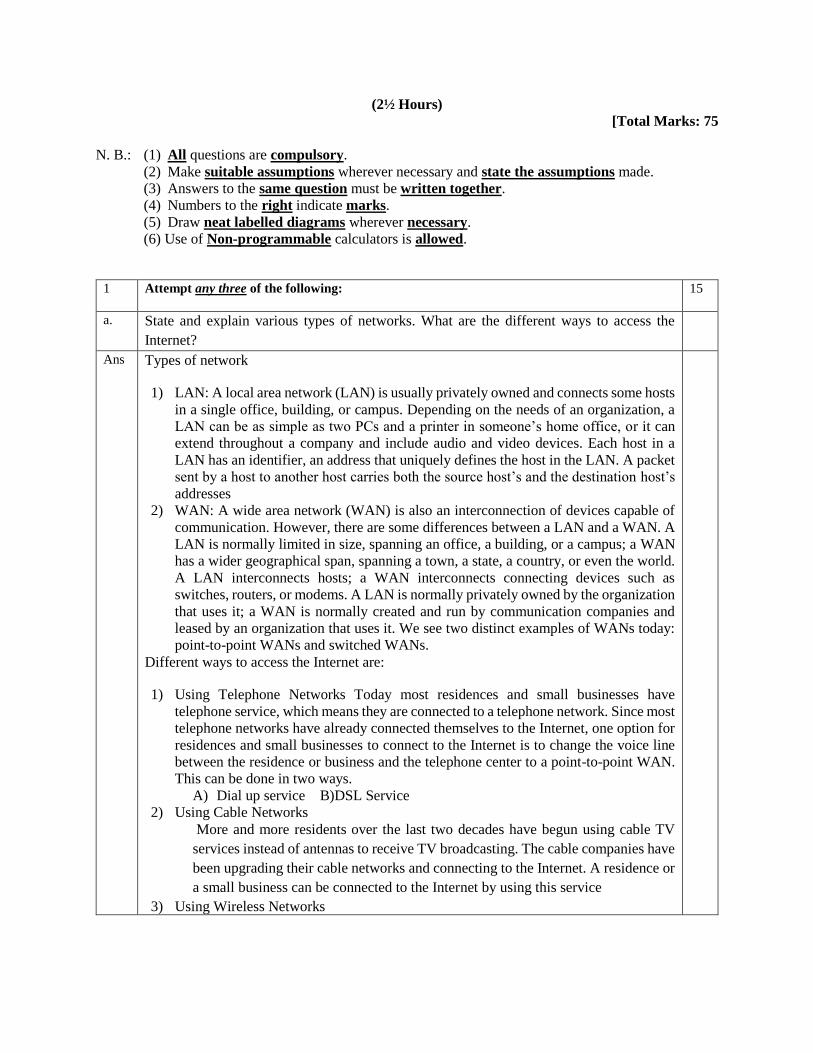
Maturity Levels An RFC, during its lifetime, falls into one of six maturity levels:
proposed standard, draft standard, Internet standard, historic, experimental, and
informational
1. Proposed Standard. A proposed standard is a specification that is stable, well
understood, and of sufficient interest to the Internet community. At this level, the
specification is usually tested and implemented by several different groups.
2. Draft Standard. A proposed standard is elevated to draft standard status after at
least two successful independent and interoperable implementations. Barring
difficulties, a draft standard, with modifications if specific problems are
encountered, normally becomes an Internet standard.
3. Internet Standard. A draft standard reaches Internet standard status after
demonstrations of successful implementation.
4. Historic. The historic RFCs are significant from a historical perspective. They
either have been superseded by later specifications or have never passed the
necessary maturity levels to become an Internet standard.
5. Experimental. An RFC classified as experimental describes work related to an
experimental situation that does not affect the operation of the Internet. Such an
RFC should not be implemented in any functional Internet service.
6. Informational. An RFC classified as informational contains general, historical, or
tutorial information related to the Internet. It is usually written by someone in a
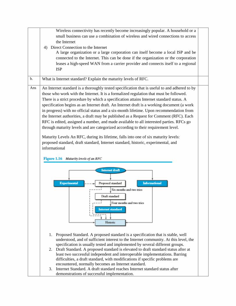
non-Internet organization, such as a vendor. c. Protocol layering can be found in many aspects of our lives such as air travelling. Imagine
you make a round-trip to spend some time on vacation at a resort. You need to go through
some processes at your city airport before flying. You also need to go through some
processes when you arrive at the resort airport. Show the protocol layering for the round
trip using some layers such as baggage checking/claiming, boarding/unboarding,
takeoff/landing.
Ans.
d. Discuss the different quality of service characteristics for overall network performance.
Ans 1) Bandwidth
One characteristic that measures network performance is bandwidth. However, the
term can be used in two different contexts with two different measuring values:
bandwidth in hertz and bandwidth in bits per second.
2) Throughput
The throughput is a measure of how fast we can actually send data through a
network. Although, at first glance, bandwidth in bits per second and throughput
seem the same, they are different. A link may have a bandwidth of B bps, but we
can only send T bps through this link with T always less than B. In other words, the
bandwidth is a potential measurement of a link; the throughput is an actual
measurement of how fast we can send data. For example, we may have a link with
a bandwidth of 1 Mbps, but the devices connected to the end of the link may handle
only 200 kbps. This means that we cannot send more than 200 kbps through this
link.
3) Latency (Delay) The latency or delay defines how long it takes for an entire message
to completely arrive at the destination from the time the first bit is sent out from the
source. We can say that latency is made of four components: propagation time,
transmission time, queuing time and processing delay
Latency = propagation time +transmission time +queuing time + processing delay
4) Bandwidth-Delay Product Bandwidth and delay are two performance metrics of a link.
However, as we will see in this chapter and future chapters, what is very important in
data communications is the product of the two, the bandwidth-delay product
5) Jitter: Another performance issue that is related to delay is jitter. We can roughly say
that jitter is a problem if different packets of data encounter different delays and the
application using the data at the receiver site is time-sensitive (audio and video data,
for example). If the delay for the first packet is 20 ms, for the second is 45 ms, and for
the third is 40 ms, then the real-time application that uses the packets endures jitter e. What are the different modes in which the transmission of binary data can be accomplished?
Explain each mode.
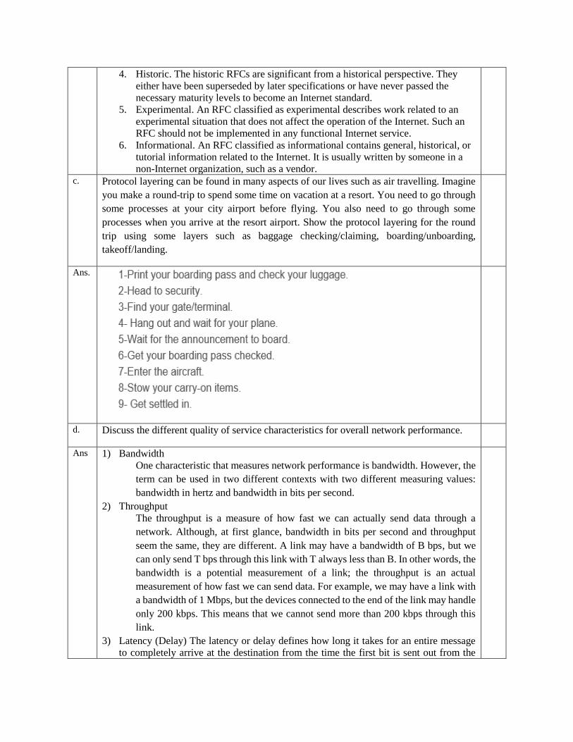
Ans. The transmission of binary data across a link can be accomplished in either parallel or serial
mode. In parallel mode, multiple bits are sent with each clock tick. In serial mode, 1 bit is
sent with each clock tick. While there is only one way to send parallel data, there are three
subclasses of serial transmission: asynchronous, synchronous, and isochronous
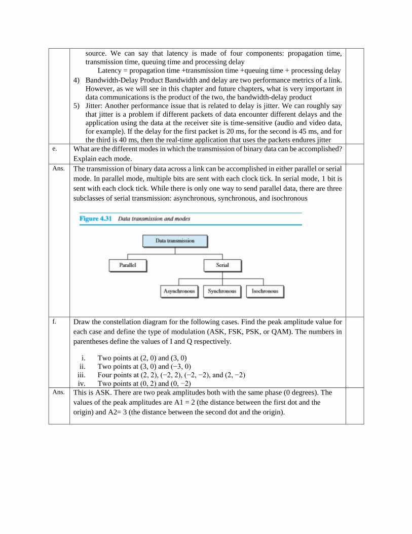
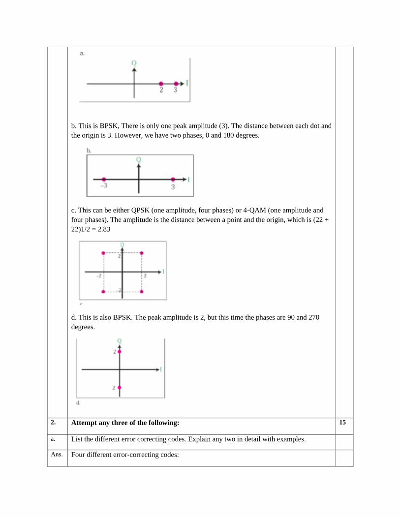
f. Draw the constellation diagram for the following cases. Find the peak amplitude value for
each case and define the type of modulation (ASK, FSK, PSK, or QAM). The numbers in
parentheses define the values of I and Q respectively.
i. Two points at (2, 0) and (3, 0)
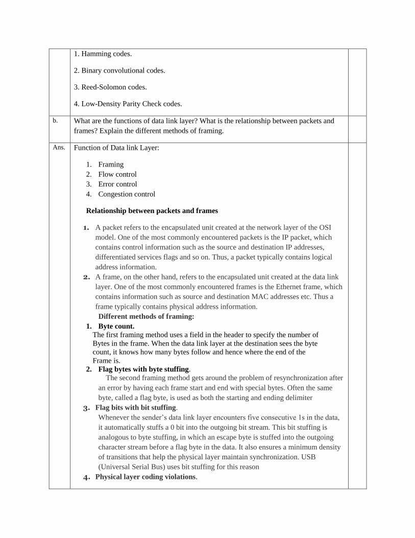
ii. Two points at (3, 0) and (−3, 0)
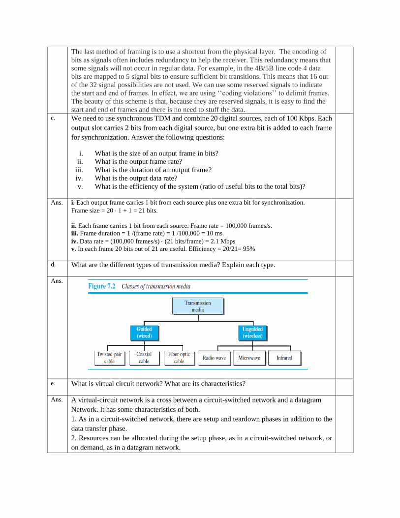
iii. Four points at (2, 2), (−2, 2), (−2, −2), and (2, −2)
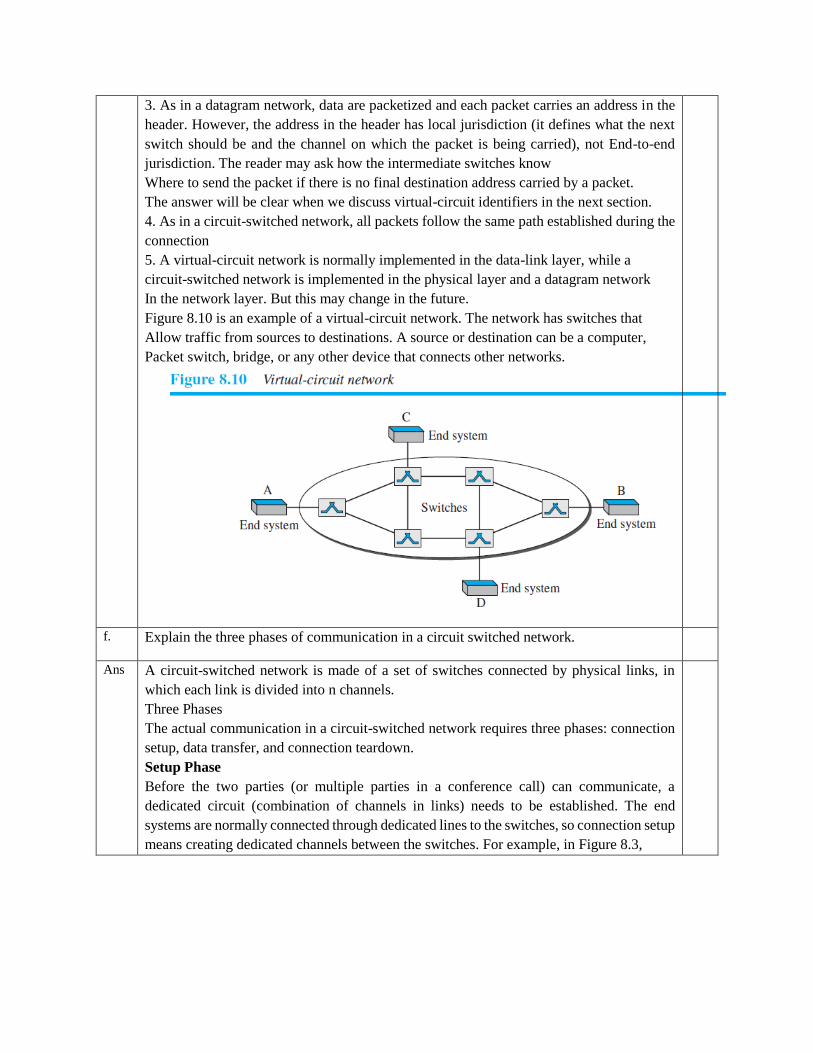
iv. Two points at (0, 2) and (0, −2)
Ans. This is ASK. There are two peak amplitudes both with the same phase (0 degrees). The
values of the peak amplitudes are A1 = 2 (the distance between the first dot and the
origin) and A2= 3 (the distance between the second dot and the origin).
b. This is BPSK, There is only one peak amplitude (3). The distance between each dot and
the origin is 3. However, we have two phases, 0 and 180 degrees.
c. This can be either QPSK (one amplitude, four phases) or 4-QAM (one amplitude and
four phases). The amplitude is the distance between a point and the origin, which is (22 +
22)1/2 = 2.83
d. This is also BPSK. The peak amplitude is 2, but this time the phases are 90 and 270
degrees.
2. Attempt any three of the following: 15
a. List the different error correcting codes. Explain any two in detail with examples.
Ans. Four different error-correcting codes:
1. Hamming codes.
2. Binary convolutional codes.
3. Reed-Solomon codes.
4. Low-Density Parity Check codes.
b. What are the functions of data link layer? What is the relationship between packets and
frames? Explain the different methods of framing.
Ans. Function of Data link Layer:
1. Framing
2. Flow control
3. Error control
4. Congestion control
Relationship between packets and frames
1. A packet refers to the encapsulated unit created at the network layer of the OSI
model. One of the most commonly encountered packets is the IP packet, which
contains control information such as the source and destination IP addresses,
differentiated services flags and so on. Thus, a packet typically contains logical
address information.
2. A frame, on the other hand, refers to the encapsulated unit created at the data link
layer. One of the most commonly encountered frames is the Ethernet frame, which
contains information such as source and destination MAC addresses etc. Thus a
frame typically contains physical address information.
Different methods of framing:
1. Byte count.
The first framing method uses a field in the header to specify the number of
Bytes in the frame. When the data link layer at the destination sees the byte
count, it knows how many bytes follow and hence where the end of the
Frame is.
2. Flag bytes with byte stuffing.
The second framing method gets around the problem of resynchronization after
an error by having each frame start and end with special bytes. Often the same
byte, called a flag byte, is used as both the starting and ending delimiter
3. Flag bits with bit stuffing.
Whenever the sender’s data link layer encounters five consecutive 1s in the data,
it automatically stuffs a 0 bit into the outgoing bit stream. This bit stuffing is
analogous to byte stuffing, in which an escape byte is stuffed into the outgoing
character stream before a flag byte in the data. It also ensures a minimum density
of transitions that help the physical layer maintain synchronization. USB
(Universal Serial Bus) uses bit stuffing for this reason
4. Physical layer coding violations.
The last method of framing is to use a shortcut from the physical layer. The encoding of
bits as signals often includes redundancy to help the receiver. This redundancy means that
some signals will not occur in regular data. For example, in the 4B/5B line code 4 data
bits are mapped to 5 signal bits to ensure sufficient bit transitions. This means that 16 out
of the 32 signal possibilities are not used. We can use some reserved signals to indicate
the start and end of frames. In effect, we are using ‘‘coding violations’’ to delimit frames.
The beauty of this scheme is that, because they are reserved signals, it is easy to find the
start and end of frames and there is no need to stuff the data. c. We need to use synchronous TDM and combine 20 digital sources, each of 100 Kbps. Each
output slot carries 2 bits from each digital source, but one extra bit is added to each frame
for synchronization. Answer the following questions:
i. What is the size of an output frame in bits?
ii. What is the output frame rate?
iii. What is the duration of an output frame?
iv. What is the output data rate?
v. What is the efficiency of the system (ratio of useful bits to the total bits)?
Ans. i. Each output frame carries 1 bit from each source plus one extra bit for synchronization.
Frame size = 20 1 + 1 = 21 bits.
ii. Each frame carries 1 bit from each source. Frame rate = 100,000 frames/s.
iii. Frame duration = 1 /(frame rate) = 1 /100,000 = 10 ms.
iv. Data rate = (100,000 frames/s) (21 bits/frame) = 2.1 Mbps
v. In each frame 20 bits out of 21 are useful. Efficiency = 20/21= 95%
d. What are the different types of transmission media? Explain each type.
Ans.
e. What is virtual circuit network? What are its characteristics?
Ans. A virtual-circuit network is a cross between a circuit-switched network and a datagram
Network. It has some characteristics of both.
1. As in a circuit-switched network, there are setup and teardown phases in addition to the
data transfer phase.
2. Resources can be allocated during the setup phase, as in a circuit-switched network, or
on demand, as in a datagram network.
3. As in a datagram network, data are packetized and each packet carries an address in the
header. However, the address in the header has local jurisdiction (it defines what the next
switch should be and the channel on which the packet is being carried), not End-to-end
jurisdiction. The reader may ask how the intermediate switches know
Where to send the packet if there is no final destination address carried by a packet.
The answer will be clear when we discuss virtual-circuit identifiers in the next section.
4. As in a circuit-switched network, all packets follow the same path established during the
connection
5. A virtual-circuit network is normally implemented in the data-link layer, while a
circuit-switched network is implemented in the physical layer and a datagram network
In the network layer. But this may change in the future.
Figure 8.10 is an example of a virtual-circuit network. The network has switches that
Allow traffic from sources to destinations. A source or destination can be a computer,
Packet switch, bridge, or any other device that connects other networks.
f. Explain the three phases of communication in a circuit switched network.
Ans A circuit-switched network is made of a set of switches connected by physical links, in
which each link is divided into n channels.
Three Phases
The actual communication in a circuit-switched network requires three phases: connection
setup, data transfer, and connection teardown.
Setup Phase
Before the two parties (or multiple parties in a conference call) can communicate, a
dedicated circuit (combination of channels in links) needs to be established. The end
systems are normally connected through dedicated lines to the switches, so connection setup
means creating dedicated channels between the switches. For example, in Figure 8.3,
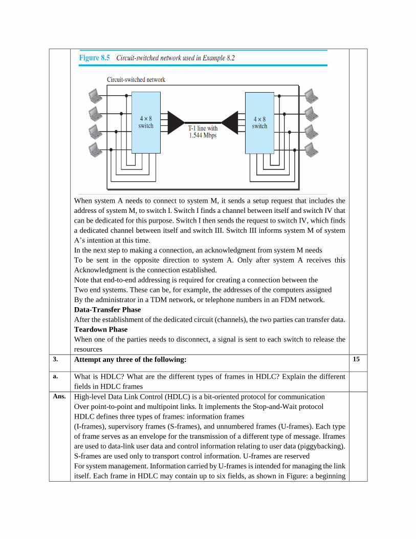
When system A needs to connect to system M, it sends a setup request that includes the
address of system M, to switch I. Switch I finds a channel between itself and switch IV that
can be dedicated for this purpose. Switch I then sends the request to switch IV, which finds
a dedicated channel between itself and switch III. Switch III informs system M of system
A’s intention at this time.
In the next step to making a connection, an acknowledgment from system M needs
To be sent in the opposite direction to system A. Only after system A receives this
Acknowledgment is the connection established.
Note that end-to-end addressing is required for creating a connection between the
Two end systems. These can be, for example, the addresses of the computers assigned
By the administrator in a TDM network, or telephone numbers in an FDM network.
Data-Transfer Phase
After the establishment of the dedicated circuit (channels), the two parties can transfer data.
Teardown Phase
When one of the parties needs to disconnect, a signal is sent to each switch to release the
resources
3. Attempt any three of the following: 15
a. What is HDLC? What are the different types of frames in HDLC? Explain the different
fields in HDLC frames
Ans. High-level Data Link Control (HDLC) is a bit-oriented protocol for communication
Over point-to-point and multipoint links. It implements the Stop-and-Wait protocol
HDLC defines three types of frames: information frames
(I-frames), supervisory frames (S-frames), and unnumbered frames (U-frames). Each type
of frame serves as an envelope for the transmission of a different type of message. Iframes
are used to data-link user data and control information relating to user data (piggybacking).
S-frames are used only to transport control information. U-frames are reserved
For system management. Information carried by U-frames is intended for managing the link
itself. Each frame in HDLC may contain up to six fields, as shown in Figure: a beginning
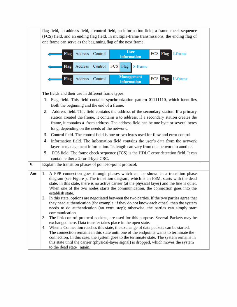
flag field, an address field, a control field, an information field, a frame check sequence
(FCS) field, and an ending flag field. In multiple-frame transmissions, the ending flag of
one frame can serve as the beginning flag of the next frame.
The fields and their use in different frame types.
1. Flag field. This field contains synchronization pattern 01111110, which identifies
Both the beginning and the end of a frame.
2. Address field. This field contains the address of the secondary station. If a primary
station created the frame, it contains a to address. If a secondary station creates the
frame, it contains a from address. The address field can be one byte or several bytes
long, depending on the needs of the network.
3. Control field. The control field is one or two bytes used for flow and error control.
4. Information field. The information field contains the user’s data from the network
layer or management information. Its length can vary from one network to another.
5. FCS field. The frame check sequence (FCS) is the HDLC error detection field. It can
contain either a 2- or 4-byte CRC.
b. Explain the transition phases of point-to-point protocol.
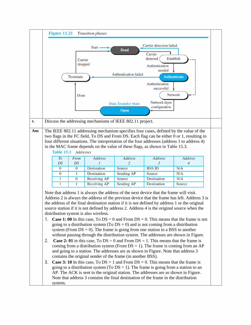
Ans. 1. A PPP connection goes through phases which can be shown in a transition phase
diagram (see Figure ). The transition diagram, which is an FSM, starts with the dead
state. In this state, there is no active carrier (at the physical layer) and the line is quiet.
When one of the two nodes starts the communication, the connection goes into the
establish state.
2. In this state, options are negotiated between the two parties. If the two parties agree that
they need authentication (for example, if they do not know each other), then the system
needs to do authentication (an extra step); otherwise, the parties can simply start
communication.
3. The link-control protocol packets, are used for this purpose. Several Packets may be
exchanged here. Data transfer takes place in the open state.
4. When a Connection reaches this state, the exchange of data packets can be started.
The connection remains in this state until one of the endpoints wants to terminate the
connection. In this case, the system goes to the terminate state. The system remains in
this state until the carrier (physical-layer signal) is dropped, which moves the system
to the dead state again.
c. Discuss the addressing mechanisms of IEEE 802.11 project.
Ans The IEEE 802.11 addressing mechanism specifies four cases, defined by the value of the
two flags in the FC field, To DS and From DS. Each flag can be either 0 or 1, resulting in
four different situations. The interpretation of the four addresses (address 1 to address 4)
in the MAC frame depends on the value of these flags, as shown in Table 15.3.
Note that address 1 is always the address of the next device that the frame will visit.
Address 2 is always the address of the previous device that the frame has left. Address 3 is
the address of the final destination station if it is not defined by address 1 or the original
source station if it is not defined by address 2. Address 4 is the original source when the
distribution system is also wireless.
1. Case 1: 00 In this case, To DS = 0 and From DS = 0. This means that the frame is not
going to a distribution system (To DS = 0) and is not coming from a distribution
system (From DS = 0). The frame is going from one station in a BSS to another
without passing through the distribution system. The addresses are shown in Figure.
2. Case 2: 01 in this case, To DS = 0 and From DS = 1. This means that the frame is
coming from a distribution system (From DS = 1). The frame is coming from an AP
and going to a station. The addresses are as shown in Figure. Note that address 3
contains the original sender of the frame (in another BSS).
3. Case 3: 10 In this case, To DS = 1 and From DS = 0. This means that the frame is
going to a distribution system (To DS = 1). The frame is going from a station to an
AP. The ACK is sent to the original station. The addresses are as shown in Figure.
Note that address 3 contains the final destination of the frame in the distribution
system.
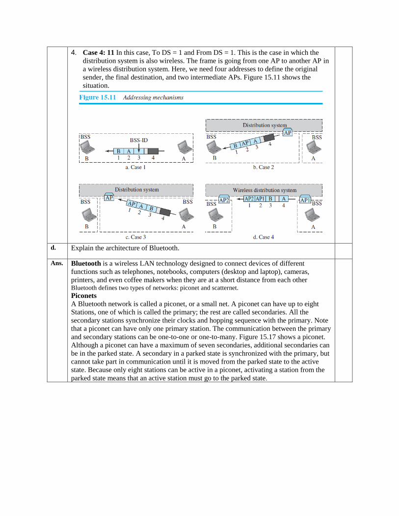
4. Case 4: 11 In this case, To DS = 1 and From DS = 1. This is the case in which the
distribution system is also wireless. The frame is going from one AP to another AP in
a wireless distribution system. Here, we need four addresses to define the original
sender, the final destination, and two intermediate APs. Figure 15.11 shows the
situation.
d. Explain the architecture of Bluetooth.
Ans. Bluetooth is a wireless LAN technology designed to connect devices of different
functions such as telephones, notebooks, computers (desktop and laptop), cameras,
printers, and even coffee makers when they are at a short distance from each other Bluetooth defines two types of networks: piconet and scatternet.
Piconets
A Bluetooth network is called a piconet, or a small net. A piconet can have up to eight
Stations, one of which is called the primary; the rest are called secondaries. All the
secondary stations synchronize their clocks and hopping sequence with the primary. Note
that a piconet can have only one primary station. The communication between the primary
and secondary stations can be one-to-one or one-to-many. Figure 15.17 shows a piconet.
Although a piconet can have a maximum of seven secondaries, additional secondaries can
be in the parked state. A secondary in a parked state is synchronized with the primary, but
cannot take part in communication until it is moved from the parked state to the active
state. Because only eight stations can be active in a piconet, activating a station from the
parked state means that an active station must go to the parked state.
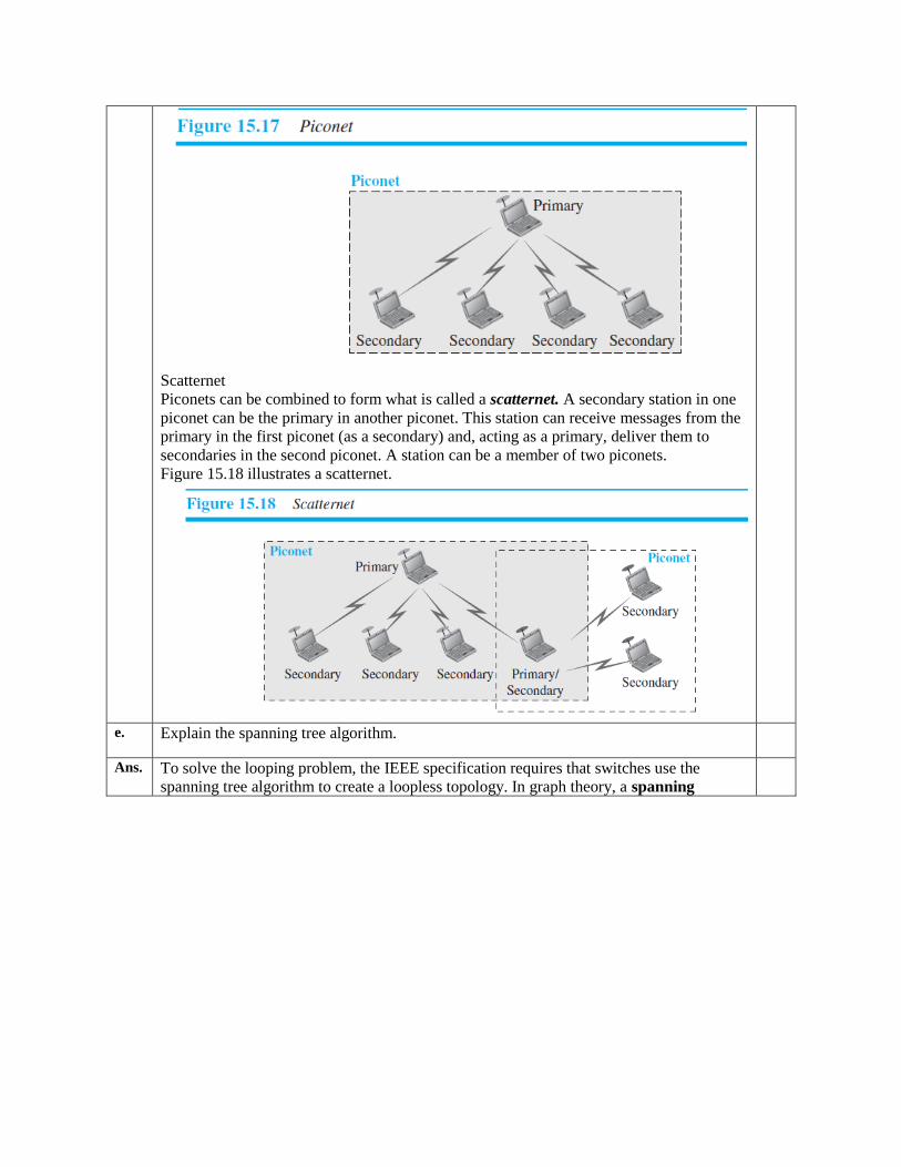
Scatternet
Piconets can be combined to form what is called a scatternet. A secondary station in one
piconet can be the primary in another piconet. This station can receive messages from the
primary in the first piconet (as a secondary) and, acting as a primary, deliver them to
secondaries in the second piconet. A station can be a member of two piconets.
Figure 15.18 illustrates a scatternet.
e. Explain the spanning tree algorithm.
Ans. To solve the looping problem, the IEEE specification requires that switches use the
spanning tree algorithm to create a loopless topology. In graph theory, a spanning
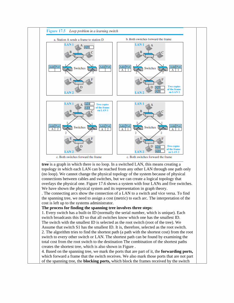
tree is a graph in which there is no loop. In a switched LAN, this means creating a
topology in which each LAN can be reached from any other LAN through one path only
(no loop). We cannot change the physical topology of the system because of physical
connections between cables and switches, but we can create a logical topology that
overlays the physical one. Figure 17.6 shows a system with four LANs and five switches.
We have shown the physical system and its representation in graph theory.
. The connecting arcs show the connection of a LAN to a switch and vice versa. To find
the spanning tree, we need to assign a cost (metric) to each arc. The interpretation of the
cost is left up to the systems administrator.
The process for finding the spanning tree involves three steps:
1. Every switch has a built-in ID (normally the serial number, which is unique). Each
switch broadcasts this ID so that all switches know which one has the smallest ID.
The switch with the smallest ID is selected as the root switch (root of the tree). We
Assume that switch S1 has the smallest ID. It is, therefore, selected as the root switch.
2. The algorithm tries to find the shortest path (a path with the shortest cost) from the root
switch to every other switch or LAN. The shortest path can be found by examining the
total cost from the root switch to the destination The combination of the shortest paths
creates the shortest tree, which is also shown in Figure .
4. Based on the spanning tree, we mark the ports that are part of it, the forwarding ports,
which forward a frame that the switch receives. We also mark those ports that are not part
of the spanning tree, the blocking ports, which block the frames received by the switch
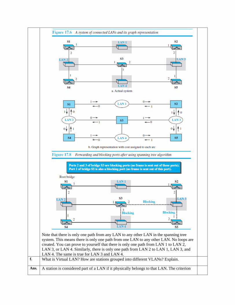
Note that there is only one path from any LAN to any other LAN in the spanning tree
system. This means there is only one path from one LAN to any other LAN. No loops are
created. You can prove to yourself that there is only one path from LAN 1 to LAN 2,
LAN 3, or LAN 4. Similarly, there is only one path from LAN 2 to LAN 1, LAN 3, and
LAN 4. The same is true for LAN 3 and LAN 4. f. What is Virtual LAN? How are stations grouped into different VLANs? Explain.
Ans. A station is considered part of a LAN if it physically belongs to that LAN. The criterion
of membership is geographic. What happens if we need a virtual connection between two
stations belonging to two different physical LANs? We can roughly define a virtual
local area network (VLAN) as a local area network configured by software, not by
Physical wiring.
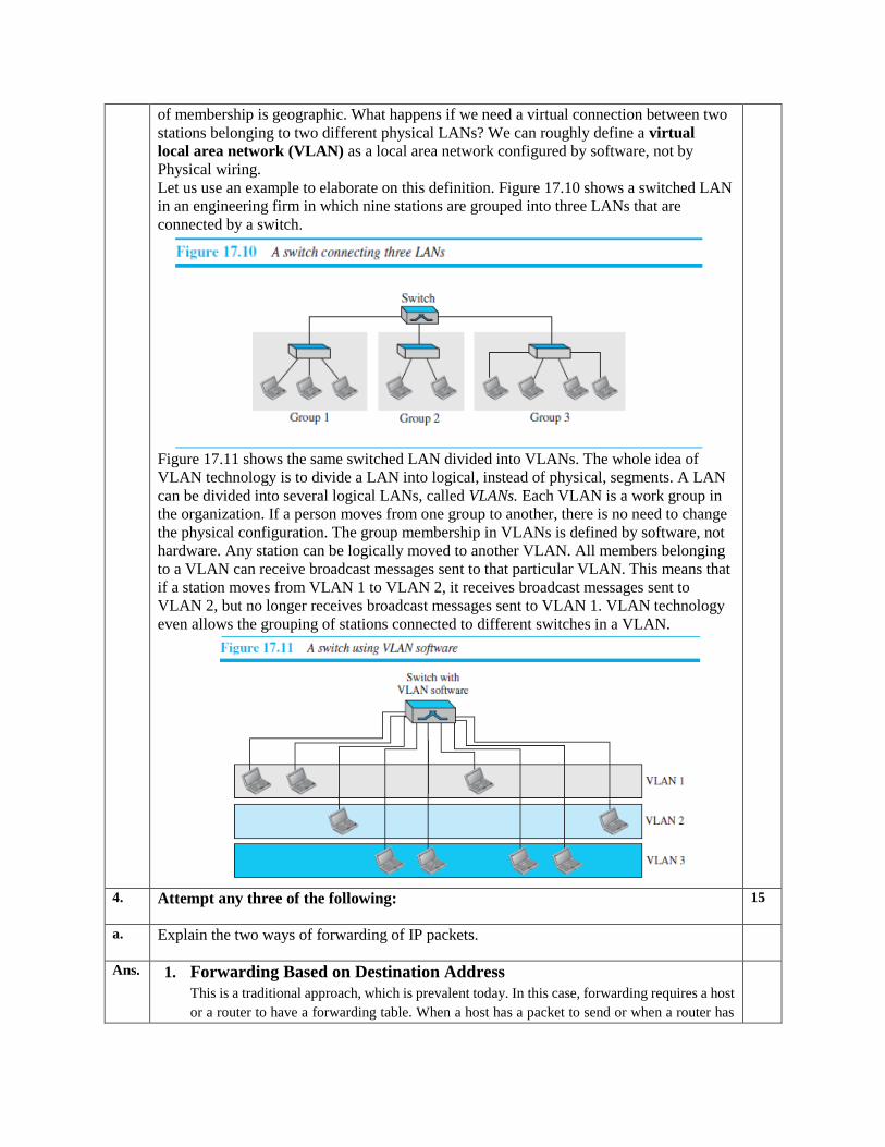
Let us use an example to elaborate on this definition. Figure 17.10 shows a switched LAN
in an engineering firm in which nine stations are grouped into three LANs that are
connected by a switch.
Figure 17.11 shows the same switched LAN divided into VLANs. The whole idea of
VLAN technology is to divide a LAN into logical, instead of physical, segments. A LAN
can be divided into several logical LANs, called VLANs. Each VLAN is a work group in
the organization. If a person moves from one group to another, there is no need to change
the physical configuration. The group membership in VLANs is defined by software, not
hardware. Any station can be logically moved to another VLAN. All members belonging
to a VLAN can receive broadcast messages sent to that particular VLAN. This means that
if a station moves from VLAN 1 to VLAN 2, it receives broadcast messages sent to
VLAN 2, but no longer receives broadcast messages sent to VLAN 1. VLAN technology
even allows the grouping of stations connected to different switches in a VLAN.
4. Attempt any three of the following: 15
a. Explain the two ways of forwarding of IP packets.
Ans. 1. Forwarding Based on Destination Address
This is a traditional approach, which is prevalent today. In this case, forwarding requires a host
or a router to have a forwarding table. When a host has a packet to send or when a router has
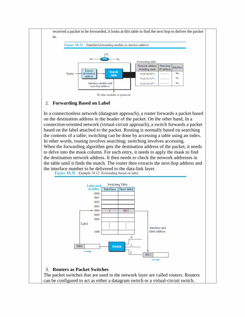
received a packet to be forwarded, it looks at this table to find the next hop to deliver the packet
to.
2. Forwarding Based on Label
In a connectionless network (datagram approach), a router forwards a packet based
on the destination address in the header of the packet. On the other hand, In a
connection-oriented network (virtual-circuit approach), a switch forwards a packet
based on the label attached to the packet. Routing is normally based on searching
the contents of a table; switching can be done by accessing a table using an index.
In other words, routing involves searching; switching involves accessing.
When the forwarding algorithm gets the destination address of the packet, it needs
to delve into the mask column. For each entry, it needs to apply the mask to find
the destination network address. It then needs to check the network addresses in
the table until it finds the match. The router then extracts the next-hop address and
the interface number to be delivered to the data-link layer.
3. Routers as Packet Switches
The packet switches that are used in the network layer are called routers. Routers
can be configured to act as either a datagram switch or a virtual-circuit switch.
b. What is dynamic host configuration protocol? Explain the DHCP message format.
Ans. A large organization or an ISP can receive a block of addresses directly from
ICANN and a small organization can receive a block of addresses from an ISP.
After a block of addresses are assigned to an organization, the network
administration can manually assign addresses to the individual hosts or routers.
However, address assignment in an organization can be done automatically using
the Dynamic Host Configuration Protocol (DHCP). DHCP is an application-layer
program, using the client-server paradigm that actually helps TCP/IP at the
network layer.
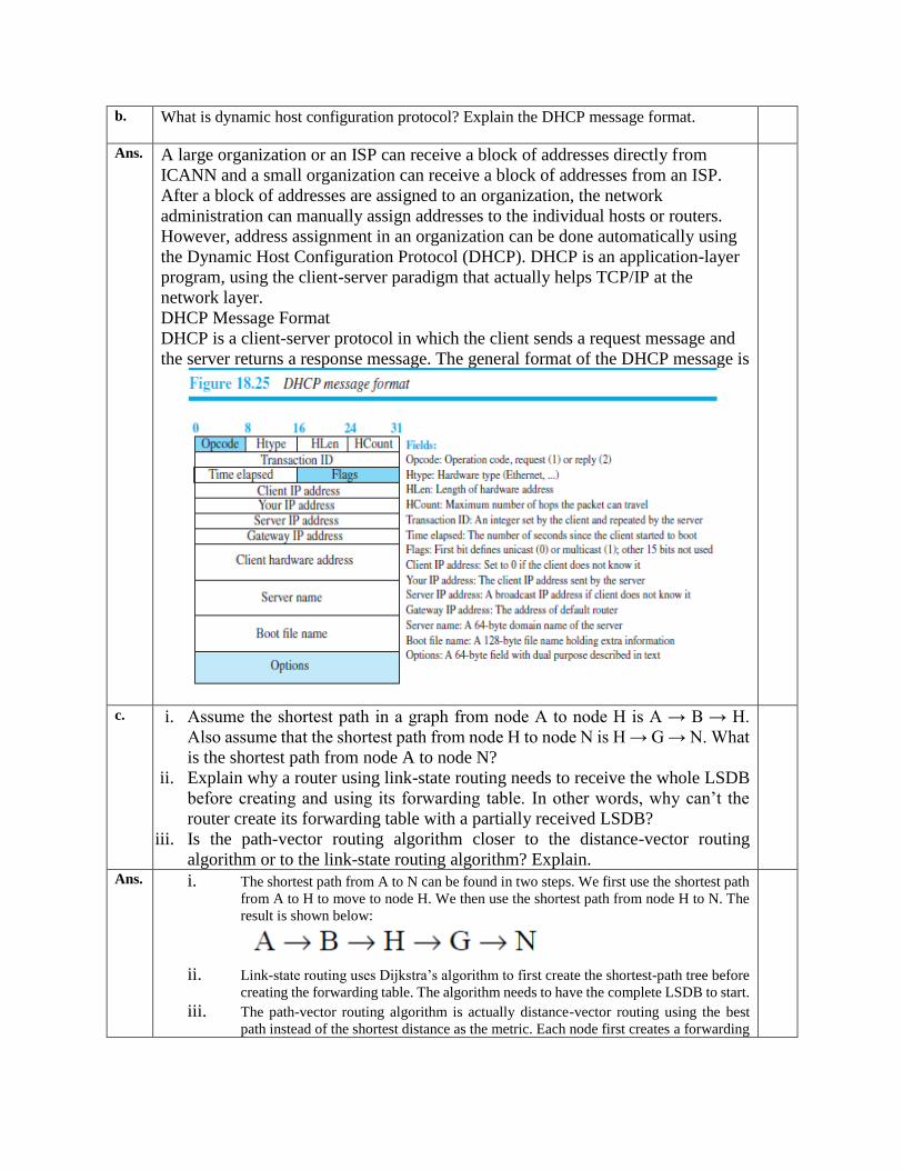
DHCP Message Format
DHCP is a client-server protocol in which the client sends a request message and
the server returns a response message. The general format of the DHCP message is
c. i. Assume the shortest path in a graph from node A to node H is A → B → H.
Also assume that the shortest path from node H to node N is H → G → N. What
is the shortest path from node A to node N?
ii. Explain why a router using link-state routing needs to receive the whole LSDB
before creating and using its forwarding table. In other words, why can’t the
router create its forwarding table with a partially received LSDB?
iii. Is the path-vector routing algorithm closer to the distance-vector routing
algorithm or to the link-state routing algorithm? Explain.
Ans. i. The shortest path from A to N can be found in two steps. We first use the shortest path
from A to H to move to node H. We then use the shortest path from node H to N. The
result is shown below:
ii. Link-state routing uses Dijkstra’s algorithm to first create the shortest-path tree before
creating the forwarding table. The algorithm needs to have the complete LSDB to start. iii. The path-vector routing algorithm is actually distance-vector routing using the best
path instead of the shortest distance as the metric. Each node first creates a forwarding
table, assuming it can only reach immediate neighbors. The forwarding table is
gradually improved as path vectors arrive from the immediate neighbors.
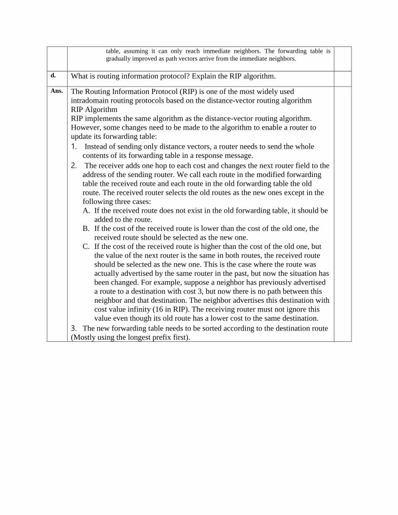
d. What is routing information protocol? Explain the RIP algorithm.
Ans. The Routing Information Protocol (RIP) is one of the most widely used
intradomain routing protocols based on the distance-vector routing algorithm
RIP Algorithm
RIP implements the same algorithm as the distance-vector routing algorithm.
However, some changes need to be made to the algorithm to enable a router to
update its forwarding table:
1. Instead of sending only distance vectors, a router needs to send the whole
contents of its forwarding table in a response message.
2. The receiver adds one hop to each cost and changes the next router field to the
address of the sending router. We call each route in the modified forwarding
table the received route and each route in the old forwarding table the old
route. The received router selects the old routes as the new ones except in the
following three cases:
A. If the received route does not exist in the old forwarding table, it should be
added to the route.
B. If the cost of the received route is lower than the cost of the old one, the
received route should be selected as the new one.
C. If the cost of the received route is higher than the cost of the old one, but
the value of the next router is the same in both routes, the received route
should be selected as the new one. This is the case where the route was
actually advertised by the same router in the past, but now the situation has
been changed. For example, suppose a neighbor has previously advertised
a route to a destination with cost 3, but now there is no path between this
neighbor and that destination. The neighbor advertises this destination with
cost value infinity (16 in RIP). The receiving router must not ignore this
value even though its old route has a lower cost to the same destination.
3. The new forwarding table needs to be sorted according to the destination route
(Mostly using the longest prefix first).
e. Draw and explain the IPv6 header format.
Ans.
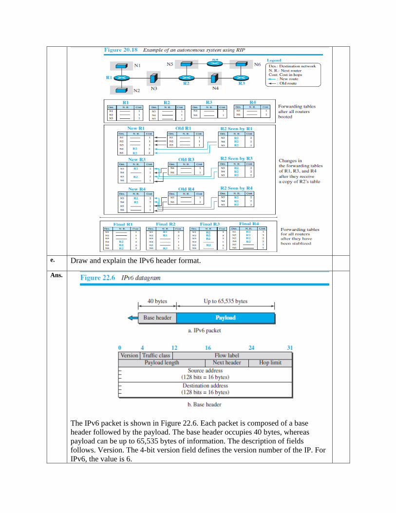
The IPv6 packet is shown in Figure 22.6. Each packet is composed of a base
header followed by the payload. The base header occupies 40 bytes, whereas
payload can be up to 65,535 bytes of information. The description of fields
follows. Version. The 4-bit version field defines the version number of the IP. For
IPv6, the value is 6.
1. Traffic class. The 8-bit traffic class field is used to distinguish different
payloads with different delivery requirements. It replaces the type-of-service
field in IPv4.
2. Flow label. The flow label is a 20-bit field that is designed to provide special
handling for a particular flow of data.
3. Payload length. The 2-byte payload length field defines the length of the IP
datagram excluding the header. Note that IPv4 defines two fields related to
the length: header length and total length. In IPv6, the length of the base
header is fixed (40 bytes); only the length of the payload needs to be defined.
4. Next header. The next header is an 8-bit field defining the type of the first
extension header (if present) or the type of the data that follows the base
header in the datagram. This field is similar to the protocol field in IPv4.
5. Hop limit. The 8-bit hop limit field serves the same purpose as the TTL field
in IPv4.
6. Source and destination addresses. The source address field is a 16-byte (128-
bit) Internet address that identifies the original source of the datagram. The
destination address field is a 16-byte (128-bit) Internet address that identifies
the destination of the datagram.
7. Payload. Compared to IPv4, the payload field in IPv6 has a different format
and Meaning f. What are the different transition strategies from IPv4 to IPv6? Explain.
Ans. Three strategies have been devised for transition: dual stack, tunneling, and header
Translation
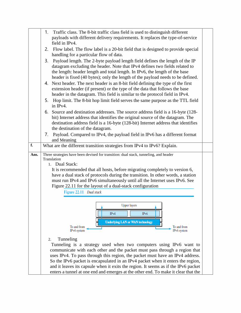
1. Dual Stack:
It is recommended that all hosts, before migrating completely to version 6,
have a dual stack of protocols during the transition. In other words, a station
must run IPv4 and IPv6 simultaneously until all the Internet uses IPv6. See
Figure 22.11 for the layout of a dual-stack configuration
2. Tunneling
Tunneling is a strategy used when two computers using IPv6 want to
communicate with each other and the packet must pass through a region that
uses IPv4. To pass through this region, the packet must have an IPv4 address.
So the IPv6 packet is encapsulated in an IPv4 packet when it enters the region,
and it leaves its capsule when it exits the region. It seems as if the IPv6 packet
enters a tunnel at one end and emerges at the other end. To make it clear that the
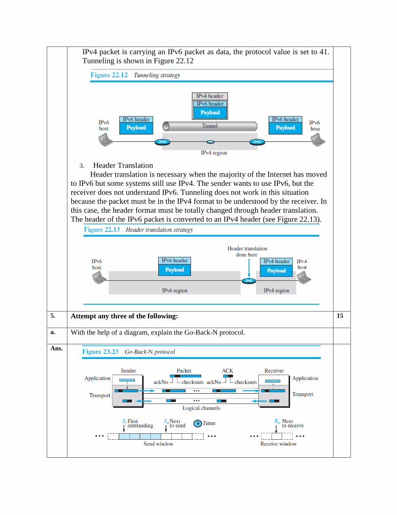
IPv4 packet is carrying an IPv6 packet as data, the protocol value is set to 41.
Tunneling is shown in Figure 22.12
3. Header Translation
Header translation is necessary when the majority of the Internet has moved
to IPv6 but some systems still use IPv4. The sender wants to use IPv6, but the
receiver does not understand IPv6. Tunneling does not work in this situation
because the packet must be in the IPv4 format to be understood by the receiver. In
this case, the header format must be totally changed through header translation.
The header of the IPv6 packet is converted to an IPv4 header (see Figure 22.13).
5. Attempt any three of the following: 15
a. With the help of a diagram, explain the Go-Back-N protocol.
Ans.
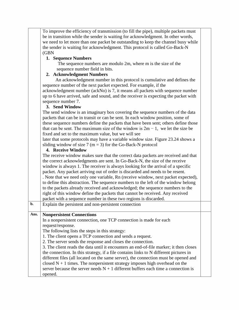
To improve the efficiency of transmission (to fill the pipe), multiple packets must
be in transition while the sender is waiting for acknowledgment. In other words,
we need to let more than one packet be outstanding to keep the channel busy while
the sender is waiting for acknowledgment. This protocol is called Go-Back-N
(GBN
1. Sequence Numbers
The sequence numbers are modulo 2m, where m is the size of the
sequence number field in bits.
2. Acknowledgment Numbers
An acknowledgment number in this protocol is cumulative and defines the
sequence number of the next packet expected. For example, if the
acknowledgment number (ackNo) is 7, it means all packets with sequence number
up to 6 have arrived, safe and sound, and the receiver is expecting the packet with
sequence number 7.
3. Send Window
The send window is an imaginary box covering the sequence numbers of the data
packets that can be in transit or can be sent. In each window position, some of
these sequence numbers define the packets that have been sent; others define those
that can be sent. The maximum size of the window is 2m − 1, we let the size be
fixed and set to the maximum value, but we will see
later that some protocols may have a variable window size. Figure 23.24 shows a
sliding window of size 7 (m = 3) for the Go-Back-N protocol
4. Receive Window
The receive window makes sure that the correct data packets are received and that
the correct acknowledgments are sent. In Go-Back-N, the size of the receive
window is always 1. The receiver is always looking for the arrival of a specific
packet. Any packet arriving out of order is discarded and needs to be resent.
. Note that we need only one variable, Rn (receive window, next packet expected),
to define this abstraction. The sequence numbers to the left of the window belong
to the packets already received and acknowledged; the sequence numbers to the
right of this window define the packets that cannot be received. Any received
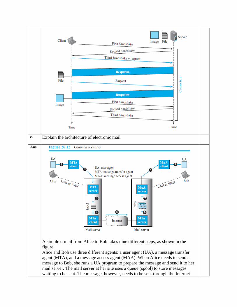
packet with a sequence number in these two regions is discarded. b. Explain the persistent and non-persistent connection
Ans. Nonpersistent Connections
In a nonpersistent connection, one TCP connection is made for each
request/response.
The following lists the steps in this strategy:
1. The client opens a TCP connection and sends a request.
2. The server sends the response and closes the connection.
3. The client reads the data until it encounters an end-of-file marker; it then closes
the connection. In this strategy, if a file contains links to N different pictures in
different files (all located on the same server), the connection must be opened and
closed N + 1 times. The nonpersistent strategy imposes high overhead on the
server because the server needs N + 1 different buffers each time a connection is
opened.
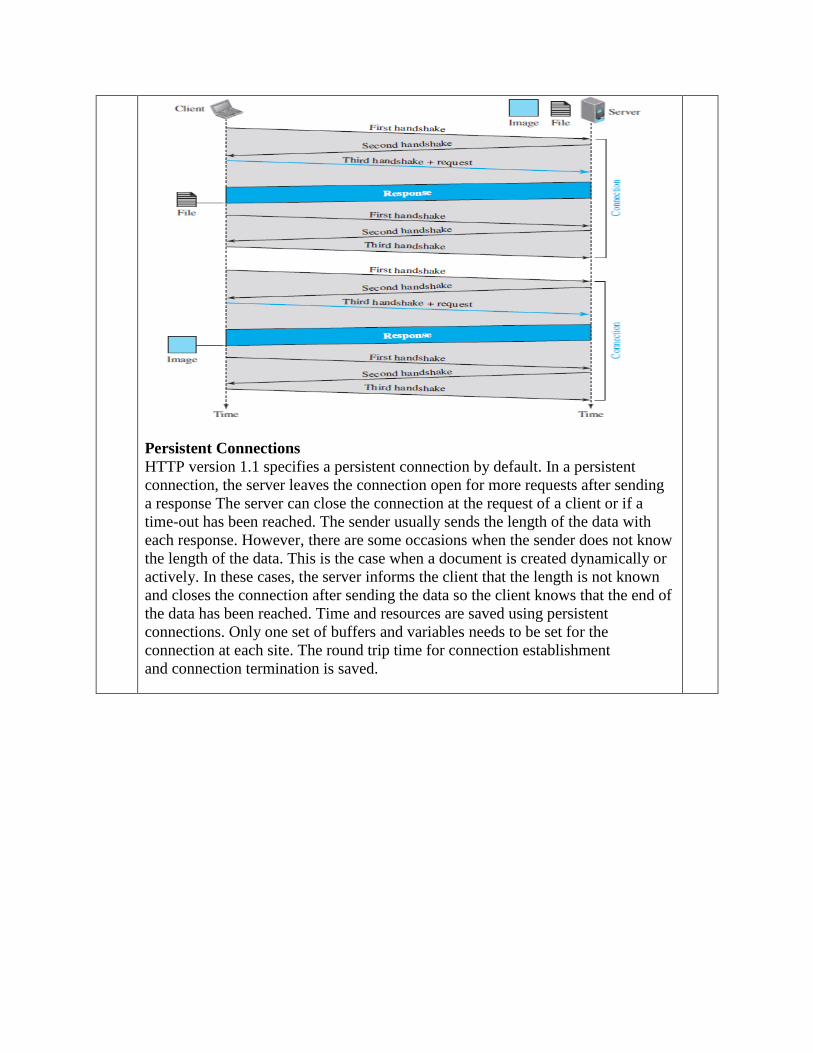
Persistent Connections
HTTP version 1.1 specifies a persistent connection by default. In a persistent
connection, the server leaves the connection open for more requests after sending
a response The server can close the connection at the request of a client or if a
time-out has been reached. The sender usually sends the length of the data with
each response. However, there are some occasions when the sender does not know
the length of the data. This is the case when a document is created dynamically or
actively. In these cases, the server informs the client that the length is not known
and closes the connection after sending the data so the client knows that the end of
the data has been reached. Time and resources are saved using persistent
connections. Only one set of buffers and variables needs to be set for the
connection at each site. The round trip time for connection establishment
and connection termination is saved.
c. Explain the architecture of electronic mail
Ans.
A simple e-mail from Alice to Bob takes nine different steps, as shown in the
figure.
Alice and Bob use three different agents: a user agent (UA), a message transfer
agent (MTA), and a message access agent (MAA). When Alice needs to send a
message to Bob, she runs a UA program to prepare the message and send it to her
mail server. The mail server at her site uses a queue (spool) to store messages
waiting to be sent. The message, however, needs to be sent through the Internet
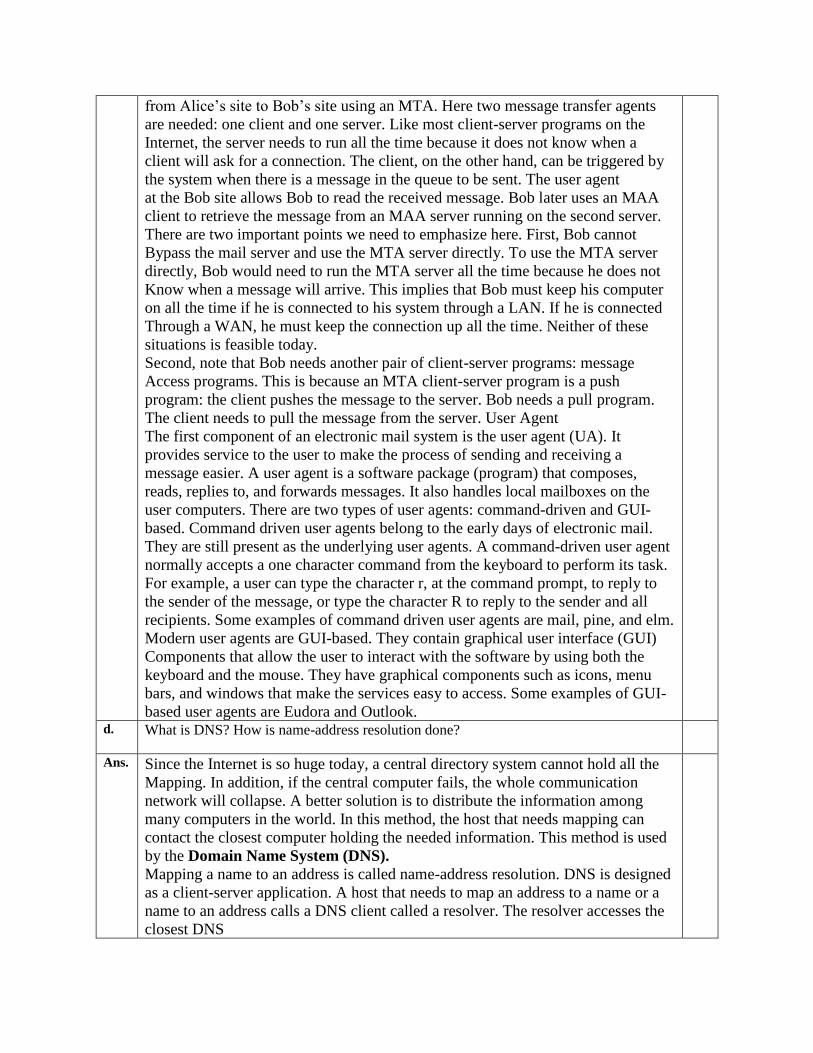
from Alice’s site to Bob’s site using an MTA. Here two message transfer agents
are needed: one client and one server. Like most client-server programs on the
Internet, the server needs to run all the time because it does not know when a
client will ask for a connection. The client, on the other hand, can be triggered by
the system when there is a message in the queue to be sent. The user agent
at the Bob site allows Bob to read the received message. Bob later uses an MAA
client to retrieve the message from an MAA server running on the second server.
There are two important points we need to emphasize here. First, Bob cannot
Bypass the mail server and use the MTA server directly. To use the MTA server
directly, Bob would need to run the MTA server all the time because he does not
Know when a message will arrive. This implies that Bob must keep his computer
on all the time if he is connected to his system through a LAN. If he is connected
Through a WAN, he must keep the connection up all the time. Neither of these
situations is feasible today.
Second, note that Bob needs another pair of client-server programs: message
Access programs. This is because an MTA client-server program is a push
program: the client pushes the message to the server. Bob needs a pull program.
The client needs to pull the message from the server. User Agent
The first component of an electronic mail system is the user agent (UA). It
provides service to the user to make the process of sending and receiving a
message easier. A user agent is a software package (program) that composes,
reads, replies to, and forwards messages. It also handles local mailboxes on the
user computers. There are two types of user agents: command-driven and GUI-
based. Command driven user agents belong to the early days of electronic mail.
They are still present as the underlying user agents. A command-driven user agent
normally accepts a one character command from the keyboard to perform its task.
For example, a user can type the character r, at the command prompt, to reply to
the sender of the message, or type the character R to reply to the sender and all
recipients. Some examples of command driven user agents are mail, pine, and elm.
Modern user agents are GUI-based. They contain graphical user interface (GUI)
Components that allow the user to interact with the software by using both the
keyboard and the mouse. They have graphical components such as icons, menu
bars, and windows that make the services easy to access. Some examples of GUI-
based user agents are Eudora and Outlook. d. What is DNS? How is name-address resolution done?
Ans. Since the Internet is so huge today, a central directory system cannot hold all the
Mapping. In addition, if the central computer fails, the whole communication
network will collapse. A better solution is to distribute the information among
many computers in the world. In this method, the host that needs mapping can
contact the closest computer holding the needed information. This method is used
by the Domain Name System (DNS).
Mapping a name to an address is called name-address resolution. DNS is designed
as a client-server application. A host that needs to map an address to a name or a
name to an address calls a DNS client called a resolver. The resolver accesses the
closest DNS
server with a mapping request. If the server has the information, it satisfies the
resolver; otherwise, it either refers the resolver to other servers or asks other
servers to provide the information.
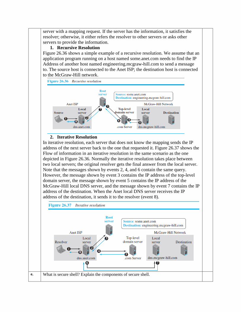
1. Recursive Resolution
Figure 26.36 shows a simple example of a recursive resolution. We assume that an
application program running on a host named some.anet.com needs to find the IP
Address of another host named engineering.mcgraw-hill.com to send a message
to. The source host is connected to the Anet ISP; the destination host is connected
to the McGraw-Hill network.
2. Iterative Resolution
In iterative resolution, each server that does not know the mapping sends the IP
address of the next server back to the one that requested it. Figure 26.37 shows the
Flow of information in an iterative resolution in the same scenario as the one
depicted in Figure 26.36. Normally the iterative resolution takes place between
two local servers; the original resolver gets the final answer from the local server.
Note that the messages shown by events 2, 4, and 6 contain the same query.
However, the message shown by event 3 contains the IP address of the top-level
domain server, the message shown by event 5 contains the IP address of the
McGraw-Hill local DNS server, and the message shown by event 7 contains the IP
address of the destination. When the Anet local DNS server receives the IP
address of the destination, it sends it to the resolver (event 8).
e. What is secure shell? Explain the components of secure shell.
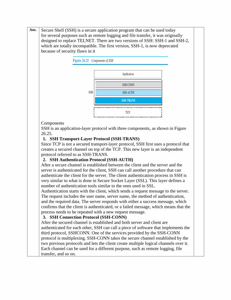
Ans. Secure Shell (SSH) is a secure application program that can be used today
for several purposes such as remote logging and file transfer, it was originally
designed to replace TELNET. There are two versions of SSH: SSH-1 and SSH-2,
which are totally incompatible. The first version, SSH-1, is now deprecated
because of security flaws in it
Components
SSH is an application-layer protocol with three components, as shown in Figure
26.25.
1. SSH Transport-Layer Protocol (SSH-TRANS)
Since TCP is not a secured transport-layer protocol, SSH first uses a protocol that
creates a secured channel on top of the TCP. This new layer is an independent
protocol referred to as SSH-TRANS.
2. SSH Authentication Protocol (SSH-AUTH)
After a secure channel is established between the client and the server and the
server is authenticated for the client, SSH can call another procedure that can
authenticate the client for the server. The client authentication process in SSH is
very similar to what is done in Secure Socket Layer (SSL). This layer defines a
number of authentication tools similar to the ones used in SSL.
Authentication starts with the client, which sends a request message to the server.
The request includes the user name, server name, the method of authentication,
and the required data. The server responds with either a success message, which
confirms that the client is authenticated, or a failed message, which means that the
process needs to be repeated with a new request message.
3. SSH Connection Protocol (SSH-CONN)
After the secured channel is established and both server and client are
authenticated for each other, SSH can call a piece of software that implements the
third protocol, SSHCONN. One of the services provided by the SSH-CONN
protocol is multiplexing. SSH-CONN takes the secure channel established by the
two previous protocols and lets the client create multiple logical channels over it.
Each channel can be used for a different purpose, such as remote logging, file
transfer, and so on.
f. In a network with fixed value for m > 1, we can either use the Go-Back-N or the Selective-
Repeat protocol. Describe the advantage and the disadvantage of using each. What other
network criteria should be considered to select either of these protocols?
Ans. The wraparound depends on the value of m.
a. In the Stop-and-Wait protocol, m 1, every 2m = 2 packets have the same sequence number.
b. In the Go-Back-N protocol with m 8, every 2m = 256 packets have the same sequence number.
c. In the Selective-Repeat protocol with m 8, every 2m = 256 packets have the same sequence
number.