Embed Size (px)
Citation preview
PHILIPS TELECOMMUNICATION PHILIPS
STB 75Combined Simplex TOR and Forward Error Correcting (FEC) system
INTRODUCTION
Large areas in the world, and many shipsfor that matter, still lack adequate meansof communication.
This communication gap can now be filledby Philips' combined Simplex TOR and forward error-correcting system, type STB-75.This low-investment equipment may beinstalled anywhere to provide access tothe world-wide telegraph network.
For instance, by itself an unprotectedradio connection is liable to errors. Itneeds, therefore, an effective means ofsuppressing mutilated characters.When used in the ARQ-mode the STB-75system upon receipt of a mutilated character will automatically request repetitionof this character and thus ensures practically error-free communication.When used in the Forward Error Correcting(FEC) mode the system is capable of correcting or indicating errors.Dozens of years of ARQ-experience havegone into the design of the STB-75 system.
Many attractive features have been builtinto the STB-75 system. As observedabove already a fully equipped systemmay be switched for two different modesof operation: ARQ-mode and FEC-mode.Each of these may be used in differentways. On a point-to-point circuit betweentwo stations the ARQ-mode is preferredbecause of its low error-rate and alsobecause the transmitted message will bereceived at the other end with certainty.Under conditions where the radio transmitter must not be used (e.g. on boardships in docks) or when the same message must be sent to several stationssimultaneously, the FEC-mode provides agood chance of gett ing the messageacross at a minimal error rate.
t
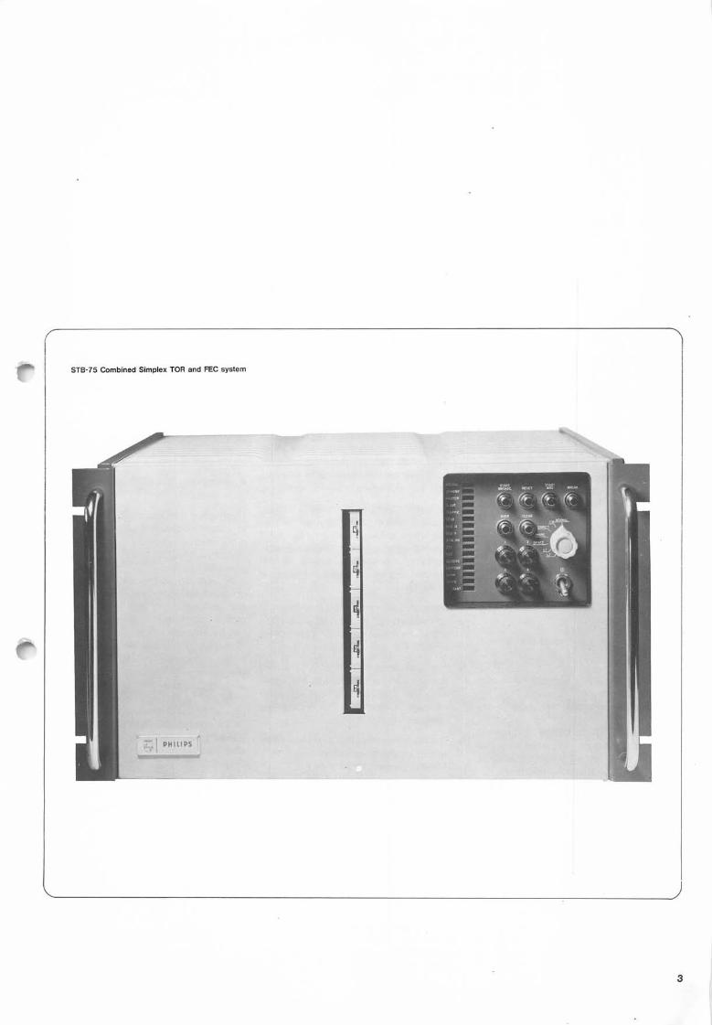
r STB-75 Combined Simplex TOR and FEC system
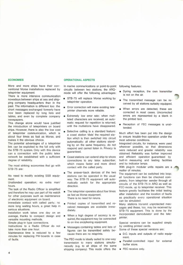
ECONOMIES OPERATIONAL ASPECTS
More and more ships have their conventional Morse installations replaced byteleprinter equipment.There is more intensive communicationnowadays between ships at sea and shipping company headquarters than in thepast. The information is different too: theshort messages exchanged formerly havenow been replaced by long lists andtables, and even by complete companynewspapers.This change alone would have justifiedthe introduction of teleprinters on boardships. However, there is also the low costof teleprinter communication, which isabout four times as fast as Morse, andmakes it the obvious choice.The potential advantages of a teleprinterlink can be exploited to the full only withthe STB-75 system. Only with this devicecan a connection with the public telexnetwork be established with a sufficientdegree of reliability.
The most striking economies that go withSTB-75 are:
No need to modify existing SSB equipment.Unattended operation; no extra man/hours.The task of the Radio Officer is simplifiedand therefore he may use part of his watchfor other purposes such as maintenanceof electronic equipment on board.Immediate contact with called party; nomore long waiting hours, a great help inserious situations.Installation work takes one day on anaverage, thanks to compact design andversatile mounting methods.Simple plug-in type connections.Instructions to a Radio Officer do nottake more than one hour.Maintenance time is reduced to a fewminutes for replacing PW-boards in caseof faults.
In marine communications or point-to-pointcircuits between two stations, the ARQ-mode will offer the following advantages:
• STB-75 will replace Morse working byteleprinter operation.
• Error correction will make existing teleprinter channels more reliable.
• Extremely low error rate: when mutilated characters are received, an automatic request for repetition is returned,until the mutilations have disappeared.
• Selective calling is a standard feature:a coast station 'dials' the required station which is then switched into circuitautomatically: all other stations standing by on the same frequency, do notrespond and cannot listen in. Privacy isguaranteed.
• Coast stations can extend ship-to-shoreconnections to any telex subscriber,which means faster and more directcontact with the called party.
• The answer-back devices of the twostations can be operated in the usualway. The STB-75 equipment will automatically switch for the appropriatedirection.
• The teleprinter operates about four timesas fast as Morse equipment.There is no need for reruns.
• Printed copies of transmitted and received messages are available immediately.
• When a high degree of secrecy is required, the equipment may be connectedto on-line enciphering equipment.
• Messages containing tables and lists offigures can be transmitted safely because there are no misprints.
The FEC-mode is ideally suited to one-waytransmission to many stations simultaneously (e.g. to all ships of the sameshipping company). This mode offers the
following features:• During reception, the own transmitter
i s n o t o n t h e a i r . * ^
• The transmitted message can be received by all stations suitably equipped.
• When errors are detected, these arecorrected in most cases. Uncorrectederrors are represented by a blank inthe printed text.
• Reception of FEC messages is unattended.
Much effort has been put into the designto ensure trouble-free operation under themost adverse conditions.Integrated circuits, for instance, were usedwherever possible, so that dimensionswere reduced and greater reliability wasobtained. Reliability was further improvedand efficient operation guaranteed bybuilt-in measuring and testing facilitiesand by indicator lamps.With plug-in modular units repairs are a --^^matter of minutes.The equipment can be switched into loop;all functions can then be checked completely, from teleprinter sender through allcircuits of the STB-75 in ARQ as well asFEC-mode, up to teleprinter receiver. Thisfeature greatly facilitates the initial testingafter installation and the location of faultsas practically every operational situationcan be simulated.Many stations transmit unprotected messages and these, too, may be received bySTB-75 equipment. This is done by theincorporated demodulator and the teleprinter.
Special versions can be supplied simplyby omitting printed cards.Some of these special versions are:• D.C. inputs and outputs of radio equip
ment.• Parallel-controlled input for external
buffer store.
• FEC receive only.
DESCRIPTION OF ARQ-MODE
GENERAL
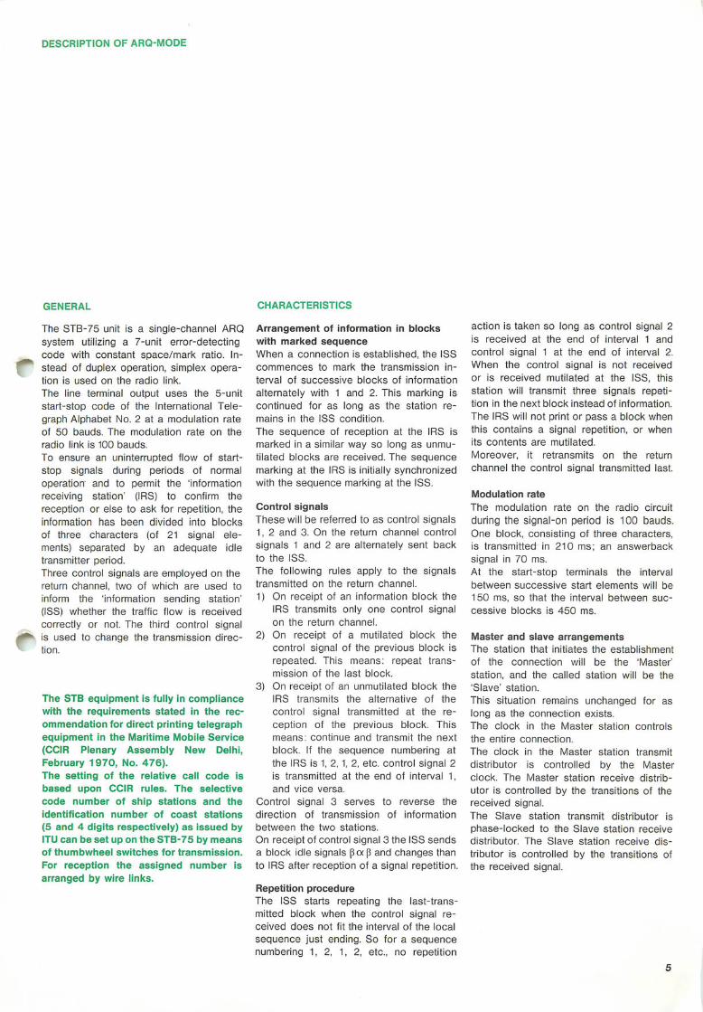
The STB-75 unit is a single-channel ARQsystem utilizing a 7-unit error-detectingcode with constant space/mark ratio. Instead of duplex operation, simplex operation is used on the radio link.The line terminal output uses the 5-unitstart-stop code of the International Telegraph Alphabet No. 2 at a modulation rateof 50 bauds. The modulation rate on theradio link is 100 bauds.To ensure an uninterrupted flow of start-stop signals during periods of normaloperation and to permit the 'informationreceiving station' (IRS) to confirm thereception or else to ask for repetition, theinformation has been divided into blocksof three characters (of 21 signal elements) separated by an adequate idletransmitter period.Three control signals are employed on thereturn channel, two of which are used toinform the 'information sending station'(ISS) whether the traffic flow is receivedcorrectly or not. The third control signalis used to change the transmission direction.
The STB equipment is fully in compliancewith the requirements stated in the recommendation for direct printing telegraphequipment in the Maritime Mobile Service(CCIR Plenary Assembly New Delh i ,February 1970, No. 476).The setting of the relative call code isbased upon CCIR rules. The selectivecode number of ship stations and theidentification number of coast stations(5 and 4 digits respectively) as issued byITU can be set up on the STB-75 by meansof thumbwheel switches for transmission.For reception the assigned number isarranged by wire links.
CHARACTERISTICS
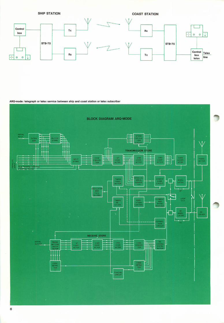
Arrangement of information in blockswith marked sequenceWhen a connection is established, the ISScommences to mark the transmission interval of successive blocks of informationalternately with 1 and 2. This marking iscontinued for as long as the station remains in the ISS condition.The sequence of reception at the IRS ismarked in a similar way so long as unmu-tilated blocks are received. The sequencemarking at the IRS is initially synchronizedwith the sequence marking at the ISS.
Control signalsThese will be referred to as control signals1, 2 and 3. On the return channel controlsignals 1 and 2 are alternately sent backto the ISS.The following rules apply to the signalstransmitted on the return channel.1) On receipt of an information block the
IRS transmits only one control signalon the return channel.
2) On receipt of a mutilated block thecontrol signal of the previous block isrepeated. This means: repeat transmission of the last block.
3) On receipt of an unmutilated block theIRS transmits the alternative of thecontrol signal transmitted at the reception of the previous block. Thismeans: continue and transmit the nextblock. If the sequence numbering atthe IRS is 1, 2,1, 2, etc. control signal 2is transmitted at the end of interval 1,and vice versa.
Control signal 3 serves to reverse thedirection of transmission of informationbetween the two stations.On receipt of control signal 3 the ISS sendsa block idle signals (3a|3 and changes thanto IRS after reception of a signal repetition.
Repetition procedureThe ISS starts repeating the last-transmitted block when the control signal received does not fit the interval of the localsequence just ending. So for a sequencenumbering 1, 2, 1, 2, etc., no repetition
action is taken so long as control signal 2is received at the end of interval 1 andcontrol signal 1 at the end of interval 2.When the control signal is not receivedor is received mutilated at the ISS, thisstation will transmit three signals repetition in the next block instead of information.The IRS will not print or pass a block whenthis contains a signal repetition, or whenits contents are mutilated.Moreover, it retransmits on the returnchannel the control signal transmitted last.
Modulation rateThe modulation rate on the radio circuitduring the signal-on period is 100 bauds.One block, consisting of three characters,is transmitted in 210 ms; an answerbacksignal in 70 ms.At the start-stop terminals the intervalbetween successive start elements will be150 ms, so that the interval between successive blocks is 450 ms.
Master and slave arrangementsThe station that initiates the establishmentof the connection will be the 'Master'station, and the called station will be the'Slave' station.This situation remains unchanged for aslong as the connection exists.The clock in the Master station controlsthe entire connection.The clock in the Master station transmitdistributor is controlled by the Masterclock. The Master station receive distributor is controlled by the transitions of thereceived signal.The Slave station transmit distributor isphase-locked to the Slave station receivedistributor. The Slave station receive distributor is controlled by the transitions ofthe received signal.
SHIP STATION COAST STATION
Control
STB-75
Txbox
\1 1
Rx-1- 0 0 I
/
Rx
STB-75
1-1- 0 o l j ]
VTx
Co*"* Telexbox
telex !Mne
ARQ-mode: telegraph or telex service between ship and coast station or telex subscriber
Phasing Rephasing
When no connection exists, both stationsare in the 'Stand-by' position. In this position no ISS or IRS status and no Masteror Slave position is assigned to either ofthe stations.The station which wants to make a callbegins to send the 'Call' signal. This 'Call'signal consists of one or two blocks of threesignals.A one-block call signal is composed ofsignal repetition followed by any combination of information signals. A two-blockcall signal contains in the first blocksignal repetition in the second character
position, and any combination of information signals in the first and third position. Thesecond block contains: signal repetitionin the third position preceded by anycombination of information signals in theother two positions.On receipt of the appropriate call signalthe called station changes from Stand-byto the Slave-IRS position and sends control signal 1.On receipt of a control signal 1, the callingstation is switched to the ISS status andsends a block of information or idle-timesignals.
When reception of information blocks orcontrol signals is continuously mutilated,the system returns to the Stand-by position after a pre-determined time of continuous repetition.Rephasing proceeds along the same linesas the procedure for phasing; however if,at the time of interruption, the Slave stationwas in the ISS position, it sends, afterrephasing, control signal 3.
NOTEComposition and assignment of call signals require international agreement.
SIGNAL SEQUENCE CHART
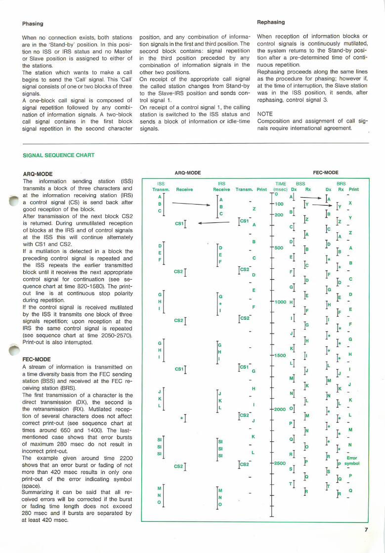
ARQ-MODEThe information sending station (ISS)transmits a block of three characters andat the information receiving station (IRS)a control signal (CS) is send back aftergood reception of the block.After transmission of the next block CS2is returned. During unmutilated receptionof blocks at the IRS and of control signalsat the ISS this will continue alternatelywith CS1 and CS2.If a mutilation is detected in a block thepreceding control signal is repeated andthe ISS repeats the earlier transmittedblock until it receives the next appropriatecontrol signal for continuation (see sequence chart at time 820-1580). The printout line is at continuous stop polarityduring repetition.If the control signal is received mutilatedby the ISS it transmits one block of threesignals repetition; upon reception at theIRS the same control signal is repeated(see sequence chart at time 2050-2570).Print-out is also interrupted.
FEC-MODEA stream of information is transmitted ona time diversity basis from the FEC sendingstation (BSS) and received at the FEC receiving station (BRS).The first transmission of a character is thedirect transmission (DX), the second isthe retransmission (RX). Mutilated reception of several characters does not affectcorrect print-out (see sequence chart attimes around 650 and 1400). The last-mentioned case shows that error burstsof maximum 280 msec do not result inincorrect print-out.The example given around time 2200shows that an error burst or fading of notmore than 420 msec results in only oneprint-out of the error indicating symbol(space).Summarizing it can be said that all received errors will be corrected if the burstor fading time length does not exceed280 msec and if bursts are separated byat least 420 msec.
ARQ-MODE FEC-MODE
ISS IRS T I M E B S S BRST r a n s m . R e c e i v e R e c e i v e Transm. P r in t ( m s e c ) D x R x D x R x P r i n t
A A H Al i T .1ABc
" B
CZ
- i o o T y --200 B l T
_ lzcl
* T X
c s i T ■ * Tcsi"1 A - I Z "
1 l A "
T B
F 1 * "
- - T I ADE
F
C S 2 T
E
F
B
C
]CS2~1 D
D.I" 5 0 0 T B
eT- T I °
F
_ T 1° I" CE g| I G "
l F "
T G
G Q T IEH
I*
F- 1 0 0 0 H
- T I fC S 2 T [CS2~ i
T I '
G G - T I "HI
HI
KI- 1 5 0 0 T l ] " 1 »
}■ 'I J "
T I "IN
csiT Tcsi-1 Gl]T ^_ m|
H " T ^J
K
L
JK
1
N
T ILL - 2 0 0 0 O
I-1 "T M
I- [ -1 R E r r o r
SI
SI
•I
SI
JCS2~1 J
K
- T I "P
T I 'Q
T >SI SIL r ]
- 2 5 0 0 r
sjT *
CS2JTcS2~ p symbo l
>] q p
M
NMN
-T
> > : «0 0
Control
STB-75
box \
Rx
-1-
L_J0 0 1
SHIP STATION(S) COAST STATION
Control
STB-75
box \
Rx
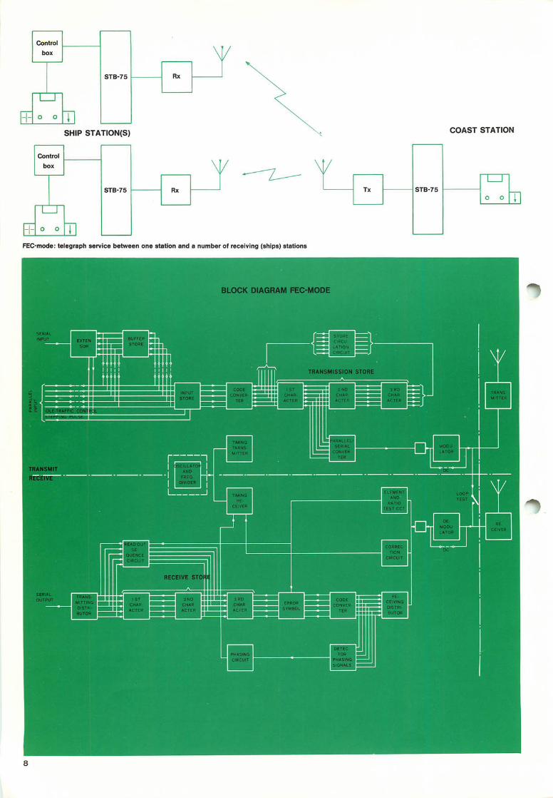
-I- 0 0 1FEC-mode: telegraph service between one station and a number of receiving (ships) stations
DESCRIPTION OF FEC-MODE
GENERAL
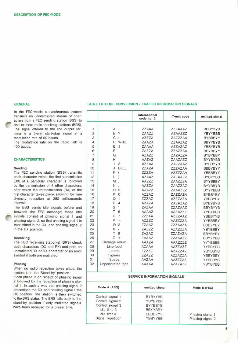
In the FEC-mode a synchronous systemtransmits an uninterrupted stream of characters from a FEC sending station (BSS) toone or more radio receiving stations (BRS).The signal offered to the line output terminal is a 5-unit start-stop signal at amodulation rate of 50 bauds.The modulation rate on the radio link is100 bauds.
CHARACTERISTICS
SendingThe FEC sending station (BSS) transmitseach character twice; the first transmission(DX) of a particular character is followedby the transmission of 4 other characters,after which the retransmission (RX) of thefirst character takes place, allowing for timediversity reception at 280 millisecondsintervals.The BSS sends idle signals before andbetween the FEC message; these idlesignals consist of phasing signal 1 andphasing signal 2, so that phasing signal 1 istransmitted in the RX, and phasing signal 2in the DX position.
ReceivingThe FEC receiving station(s) (BRS) checkboth characters (DX and RX) and print anunmutilated DX or RX character or an errorsymbol if both are mutilated.
PhasingWhen no radio reception takes place, thesystem is in the 'Stand-by' position.It can phase-in on receipt of phasing signal2 followed by the reception of phasing signal 1, in such a way that phasing signal 2determines the DX and phasing signal 1 theRX position. The station is then switchedto the BRS status. The BRS falls back to thestand-by position if only mutilated signalshave been received for a preset time.
TABLE OF CODE CONVERSION / TRAFFIC INFORMATION SIGNALS
Internationalcode no. 2 7-unit code emitted signal
1 A - ZZAAA ZZZAAAZ BBBYYYB2 B ? ZAAZZ AZAAZZZ YBYYBBB3 C : AZZZA ZAZZZAA BYBBBYY4 D WRU ZAAZA ZZAAZAZ BBYYBYB5 E 3 ZAAAA AZZAZAZ YBBYBYB6 F ZAZZA ZZAZZAA BBYBBYY7 G AZAZZ ZAZAZZA BYBYBBY8 H AAZAZ ZAAZAZZ BYYBYBB9 I 8 AZZAA ZAZZAAZ BYBBYYB
10 J BELL ZZAZA ZZZAZAA BBBYBYY11 K ( ZZZZA AZZZZAA YBBBBYY12 L ) AZAAZ ZAZAAZZ BYBYYBB13 M . AAZZZ ZAAZZZA BYYBBBY14 N , AAZZA ZAAZZAZ BYYBBYB15 O 9 AAAZZ ZAAAZZZ BYYYBBB16 P 0 AZZAZ ZAZZAZA BYBBYBY17 Q 1 ZZZAZ AZZZAZA YBBBYBY18 R 4 AZAZA ZAZAZAZ BYBYBYB19 S ' ZAZAA ZZAZAAZ BBYBYYB20 T 5 AAAAZ AAZAZZZ YYBYBBB21 U 7 ZZZAA AZZZAAZ YBBBYYB22 V = AZZZZ AAZZZZA YYBBBBY23 W 2 ZZAAZ ZZZAAZA BBBYYBY24 X / ZAZZZ AZAZZZA YBYBBBY25 Y 6 ZAZAZ ZZAZAZA BBYBYBY26 Z + ZAAAZ ZZAAAZZ BBYYYBB27 Carriage return AAAZA AAAZZZZ YYYBBBB28 Line feed AZAAA AAZZAZZ YYBBYBB29 Letters ZZZZZ AZAZZAZ YBYBBYB30 Figures ZZAZZ AZZAZZA YBBYBBY31 Space AAZAA AAZZZAZ YYBBBYB32 Unperforated tape AAAAA AZAZAZZ YBYBYBB
SERVICE INFORMATION SIGNALS
Mode A (ARQ) emitted signal Mode B (FEC)
Control signal 1 BYBYYBBcontrol signal 2 YBYBYBBcontrol signal 3 BYYBBYB
Idle time 6 BBYYBBYIdle time ex BBBBYYY Phasing signal 1
signal repetition YBBYYBB Phasing signal 2
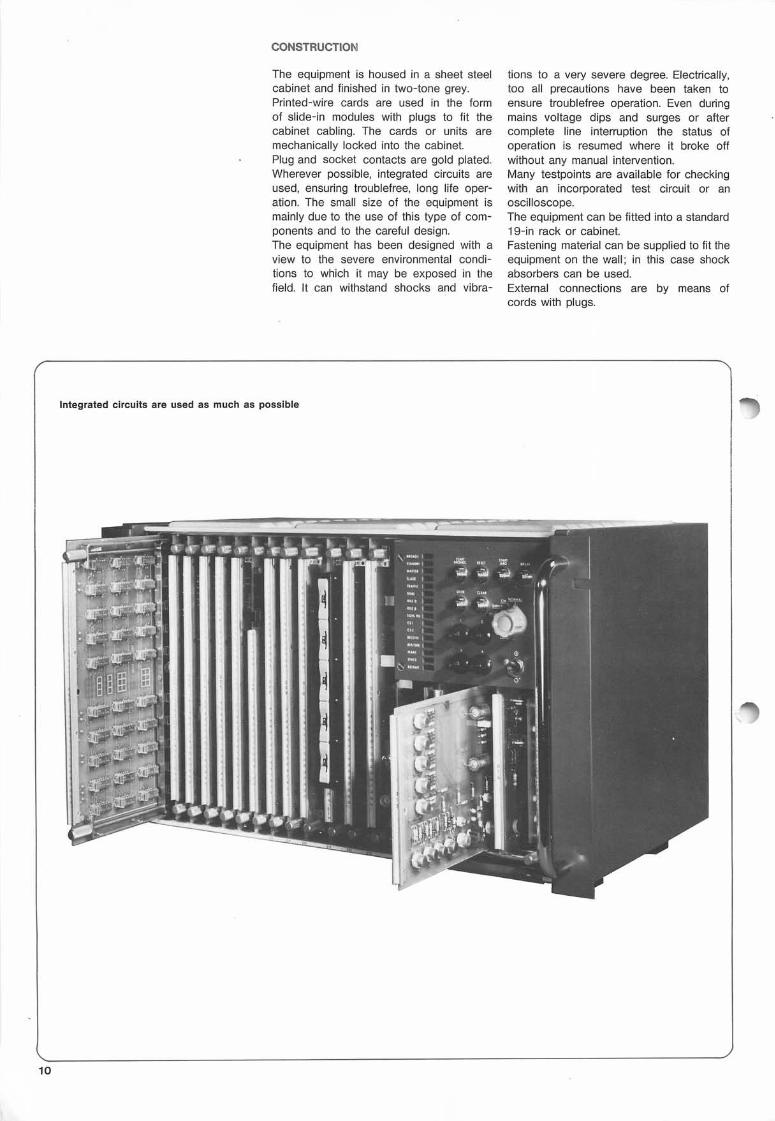
CONSTRUCTION
The equipment is housed in a sheet steelcabinet and finished in two-tone grey.Printed-wire cards are used in the formof slide-in modules with plugs to fit thecabinet cabling. The cards or units aremechanically locked into the cabinet.Plug and socket contacts are gold plated.Wherever possible, integrated circuits areused, ensuring troublefree, long life operation. The small size of the equipment ismainly due to the use of this type of components and to the careful design.The equipment has been designed with aview to the severe environmental conditions to which it may be exposed in thefield. It can withstand shocks and vibra
tions to a very severe degree. Electrically,too all precautions have been taken toensure troublefree operation. Even duringmains voltage dips and surges or aftercomplete line interruption the status ofoperation is resumed where it broke offwithout any manual intervention.Many testpoints are available for checkingwith an incorporated test circuit or anoscilloscope.The equipment can be fitted into a standard19-in rack or cabinet.Fastening material can be supplied to fit theequipment on the wall; in this case shockabsorbers can be used.External connections are by means ofcords with plugs.
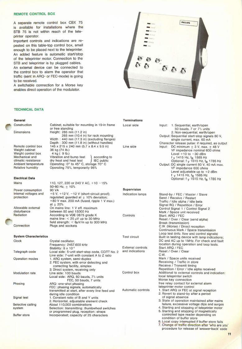
REMOTE CONTROL BOX
A s e p a r a t e r e m o t e c o n t r o l b o x C B X 7 5i s a v a i l a b l e f o r i n s t a l l a t i o n s w h e r e t h eSTB 75 is not w i th in reach o f the te leprinter operator.Important controls and indicat ions are repeated on this table-top control box, smallenough to be placed next to the teleprinter.An added fea tu re i s au tomat ic s ta r t /s topof the teleprinter motor. Connection to theSTB and teleprinter is by plugged cables.An ex terna l dev ice can be connected tothe control box to alarm the operator thattraffic (sent in ARQ- or FEC-mode) is goingto be received.A swi tchable connect ion for a Morse keyenables direct operation of the modulator.
TECHNICAL DATA
General
^ - C o n s t r u c t i o n
Dimensions
Remote control boxWeight cabinetWeight control boxMechanical andclimatic resistanceAmbient temperatureRelative humidity
Electrical DataMains
Power consumptionInternal voltages andprotection
Allowable externaldisturbanceRadiation
Connection
System CharacteristicsClock
Telegraph code
Operation modes
Modulation rate
Phasing
Signal test
Selective callingsystem
Buffer store
for rack mounting(excluding flanges)(without handles)
Cabinet, suitable for mounting in 19-in frameor free standingHeight: 285 mm (11.2 in)
265 mm (10.4 inWidth : 440 mm (17.3 inDepth : 300 mm (11.8 in145 x 215 x 240 mm (5.7 x 8.4 x 9.5 in)36 kg (74 lb.)
4 kg ( 9 lb.)Vibration and bump test 1 according todry heat and heat test / IEC publicOperating: 0° to 45° C, storage 70° COperating 75%, temporarily 95%
110, 127, 220 or 240 V AC, +10 -15%50-60 Hz, ± 10%90 VA+ 5V, +12 V, -12 V (short-circuit proof);regulated; guarded at ± 10% deviation;+ 80 V max. 200 mA (fused, ripple 1 V max.)at ± 20%On mains line: 1 V eff. maximumbetween 50 and 15000 HzAccording to VDE 0875 grade Kmains line: < 25 )uV up to 30 MHzfield strength: < 6^iV/m up to 300 MHzPlugs and sockets
TerminationsLocal side
Line side
Crystal oscillator,Frequency: 2457.600 kHzStability: 5 x10sLocal side: 5-unit start-stop code, CCITT No. 2Line side: 7-unit with constant A to Z ratio1. ARQ system, semi-duplex2. FEC system, with error detecting and
correcting facility, simplex3. Direct system, receiving onlyLine side: 100 baudsLocal side: ARQ, 50 bauds, 7Vi units
FEC, 50 bauds, 7 unitsARQ: one-shot phasingFEC: phasing signals, automaticallytransmitted at start, after every line feed andduring idle condition1. Constant ratio of B and Y units2. Horizontal, adjustable element checkAbout 110,000 combinationsSelection: transmitting: thumbwheel switchesor programmed plug, reception: strapsIncorporated; capacity of 25 characters
SupervisionIndication lamps
Controls
Test circuit
External controlsand indications
Control box
Automatic controls
Input: 1. Sequential, earth/open50 bauds, 7 or 7% units
2. Non-sequential, earth/openOutput: Sequential start-stop signals 80 V,
single current, max. 60 mACharacter release pulse: if required, as outputInput: DC minimum ± 3 V, max. + 48 V
VF impedance nominal 600 ohmsLevel +10 to -30 dBmf y 1415 Hz, fB 1585 HzOptional: f y 1615 Hz, fB 1785 Hz
Output: DC single current 80 V, 40 mA max.VF impedance 600 ohmsLevel adjustable up to +2 dBmf y 1415 Hz, fB 1585 HzOptional: f y 1615 Hz, fB 1785 Hz
Stand-by / FEC / Master / SlaveSend / Receive / RestartTraffic / Idle alpha / Idle betaSignal RQ / Repetition / ErrorControl Signal 1 / Control Signal 2Mark / Space unit receivedStart: ARQ / FECReset / Over / Clear (send alpha)Break (transmission)C.W. (Morse) / Direct receptionContinuous Mark / Space transmissionLoop test (info, flow and control signals)Built-in testing device with lamp indications;DC and AC up to 1 MHz. For check and faultlocation during operation and loop tests.Start ARQ / FECReset / Over / ClearC.W.Mark / Space units receivedReceiving / Traffic in storeReceive / Transmit timingRepetition / Error / Idle alpha receivedAdditional to external controls and indication:local teleprinter switchMorse key connectionfree relay contact for external alarmteleprinter motor control1. Start ARQ or FEC at signal reception2. Revert to stand-by after a period
of signal absence3. State of operation maintained after mains
failure, excessive voltage dips and surges4. Starting and stopping of teleprinter motor5. Starting and stopping of magnetically
controlled tape reader depending oncondition of buffer store
6. Local copy interrupted if buffer store fails7. Change of traffic direction after 'who are you'
procedure for release of 'answer-back' code
11

PHILIPS' TELECOMMUNICATE INDUSTRIE B.V.TELEPHONE INT. + 31 2150 92953TELEX 11274P.O.B. 32, HILVERSUM 1301THE NETHERLANDS
Printed in The Netherlands by Ahrend-Globe, HilversumData subject to alteration without notice
TDS 2786 - 2000 E - 02-74