Embed Size (px)
Citation preview

3679 S Huron Street, Suite 404 Englewood, Colorado 80110
Phone: (303) 789-4111 FAX: (303) 789-4310
S U B M I T T A L T R A N S M I T A L
March 8, 2013 Submittal No: 14500-001
PROJECT: Harold Thompson Regional WRF Birdsall Rd. Fountain, CO 80817 Job No. 2908
ENGINEER: GMS, Inc. 611 No. Weber St., #300 Colorado Springs, CO 80903 719-475-2935 Roger Sams
OWNER: Lower Fountain Metropolitan Sewage Disposal District 901 S. Santa Fe Ave. Fountain, CO 80817 719-382-5303 James Heckman
CONTRACTOR: Serpentix Conveyor Corporation
9085 Marshall Ct. Westminster, CO 80031 Robert D. Nusz, President
Office: 303-430-8427 Direct: 303-446-7973 www.serpentixconveyor.com
SUBJECT: Belt Conveyor SPEC SECTION: 14550 PREVIOUS SUBMISSION DATES: DEVIATIONS FROM SPEC: YES X NO CONTRACTOR’S STAMP: This submittal has been reviewed by Weaver Construction Management and, unless indicated otherwise, has been found to be in conformance with the intent of the contract documents.
Contractor’s Stamp: Engineer’s Stamp: Date: 3/8/13 Reviewed by: Solange Huggins ( ) Reviewed Without Comments ( x ) Reviewed With Comments

ENGINEER’S COMMENTS:_________________________________________________________________________________________________________________________________

7911 Shaffer Parkway, Littleton, Colorado 80127 Phone: 303.791.3600 Fax: 303.791.1801 www.weavercm.com
Project: HDTWRF Project Location: Fountain, CO Supplier: Serpentix Date: 3/7/13 Submittal: Belt Conveyor‐14550‐01 Additional Submittal Review Comments:
1) Per 2.2 D. 2. c –Motor enclosure type is specified as TEFC, nameplate motor data sheet shows the enclosure as TE, but elsewhere in the submittal it is shown TEFC. Supplier to confirm that motor enclosure will be TEFC.
2) Per 1.5 B. 6‐ Job Conditions, site elevation is shown as 5,430’; rating on motor is at 3,300’. We have been told that because of the size of the motor, this should not be an issue.
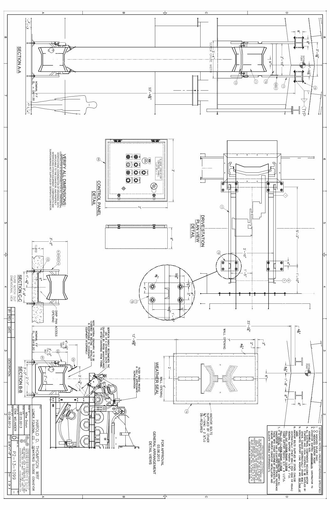
3) Drawing L01 of the control panel is missing a button identified as “Overtorque Fault”. 4) Supplier to verify that color of buttons on panel complies with specification. 5) Coordination with building manufacturer is required. In reference to the note from Serpentix
on drawing P2‐13‐1099, sheet 1 of 3, Serpentix will be providing the support connections to the building frame for support of the belt conveyor. Engineered drawings are forthcoming by Serpentix.
Reviewed by Solange Huggins End of Review

����
9085�Marshall�Court��|��Westminster,�CO�80031Ͳ2920�–�USA�Toll Free: 1.800.466.7979 | Direct: 303.430.8427 | Fax: 303.430.7337 | serpentixconveyor.com | Email: [email protected]
�
SERPENTIX CONVEYOR CORP.
March 6, 2013 Weaver Construction Management, Inc. 3679 South Huron St, Suite 404 Englewood, CO 80110 [email protected] Cell Phone: 303-917-4593 Fax: 303-789-4310 Attention: Mr. John Jacob Project Manager Reference: HDTWRF Submittal No. 1
Your P.O. #9103-14550 Dated: 2-1-13 Specification Section: 14550 Our Job No.: P2-13-1099 Dear Mr. Jacob: Enclosed is our submittal for the sludge conveyor. All equipment and materials comply with specification section 14550. Please verify all dimensions, and coordinate as necessary with all subcontractors and equipment suppliers to insure equipment compatibility. Upon our receipt of all drawings and submittal data approved, we will require 14-16 weeks to fabricate and ship this equipment. Please schedule accordingly. Please contact me if you have any questions regarding this equipment. Thank you. Sincerely, Robert D. Nusz Project Manager Enc.: 2 sets of submittals / 1 electronic submittal copy cc: Mr. Scott Marshall, Miscowater

9085 Marshall Court | Westminster, CO 80031-2920 – USA Toll Free: 1.800.466.7979 | Direct: 303.430.8427 | Fax: 303.430.7337 | serpentixconveyor.com | Email: [email protected]
SERPENTIX CONVEYOR CORP.
Wednesday March 6th, 2013
Serpentix Job Name: Lower Fountain, CO
Submittal No. 1 x CONTRACTOR/PURCHASER: Garney Companies, Inc. x PURCHASE ORDER NUMBER: 9103-14550 x OUR JOB NUMBER: P2-13-1099 x SPECIFICATION SECTION: 14550 STANDARD CATALOG DATA x Electric Motor Data Sheets x Gear Reducer Data Sheets x Safety Stop Switch Data Sheets x Zero Motion Speed Switch Data x Serpentix Data Sheets regarding main components (Drive Station, Scraper, Tension Station, Spare Parts) GENERAL ARRANGEMENT DRAWINGS x P2-13-1099-D Sheet 1 of 3 General Conveyor Configuration with
Track, Support and Miscellaneous Bill of Material Call-Outs x P2-13-1099-D Sheet 2 of 3 End View Details and Control Panel x P2-13-1099-D Sheet 3 of 3 Standard Moving Parts and Standard Accessory Bill of
Material Call-Outs

Drive Station Motor

Catalog Number: H2P2D Model: AS73Hp: 2 Phase: 3 Volts: 208-230/460HZ: 60/50RPM: 1750 Amps: 6-5.7/2.8Insul Class: F SF: 1.15 SFA: 6.7-6.2/3.1Max Ambient: 40 NEMA Frame: 145T Encl: TE Code: MShaft End Bearing: 6205-2Z-J/C3 Opp End Bearing: 6203-2Z-J/C3NEMA Nom Eff: 86.5 Thermally Protected: N/A Type: CTE
Motor Specifications
Electrical Break Down Torque 506 PERCENT OF FLT Locked Rotor Torque 395 PERCENT OF FLT Locked Rotor Amps 26.2
Mechanical
Mounting HORZ-FOOTED
General PurposeThree Phase, Totally Enclosed Fan Cooled (TEFC)Hostile Duty®Premium Efficient
List Price: Discount Symbol: DS-3XE Weight: 50 lbsCatalog Page (PDF)
Technical DataThe information you have requestedis currently not availableelectronically. Please contact yourNidec Customer ServiceRepresentative or call1-888-637-7333.
The motor shown is representative of the product family and not specifically the individual rating.© 2010 Nidec Motor Corporation. All rights reserved.Terms and Conditions of Use

VARIABLEFREQUENCY
C-FACEMOTORS
HAZARDOUSLOCATION
COOLINGTOW
ERDUTY
GENERALPURPOSE
AUTOMOTIVE
DUTYGENERAL
PURPOSEHAZARDOUS
LOCATIONGENERAL
PURPOSEOPEN
DRIPPROOFGENERAL
PURPOSEe-LINE
®
GENERALPURPOSE
841PLUS
®
GENERALPURPOSE
CORRO-DUTY®
GENERALPURPOSE
HOSTILEDUTY
GENERALPURPOSE
UNIMOUNT
®
www.nidec-motor.com 11
FEATURES:
• World Motor®
Features, Except Where Noted
• Class F Insulation, Class B Rise At Full Load On 60 Hertz Sine Wave Power
• Cast Iron Frame (140: Rolled Steel), Cast Iron End Brackets
• Corrosion Resistant Mill & Chemical Duty Paint
• Stainless Steel Nameplate (with CE Mark) & Zinc Plated Hardware
• Shaft Slinger On Pulley End For IP54 Protection
• Dual Voltage 230/460 Volts (1-100 HP)
• 40°C Ambient, NEMA®†
Design B Performance On 60 Hertz Sine Wave Power
• Regreasable Ball Bearings 250 Frame & Up, Lifting Provisions 180 Frame & Up
• Double Shielded Bearings 140-360, Open On 400-440
• 1.15 Service Factor @ 60 Hz
• Steel Fan Cover & Conduit Box
• Field Convertible To F2 Mounting 180 Frame & Larger
• Condensation Drains With Plastic Plugs
• Conversion Kits: All Cast Iron Upgrade, C&D Flanges, Drip Cover Kits (except
320-360), See Pages 260-266
APPLICATIONS:
For pulp & paper plants, saw mills, mines, foundries, chemical plants, waste management facilities, and other
process-related industries requiring protection within harsh operating conditions.
Note 03 60/50 Hz rated with no derate on HP; 230/460 volt 60 Hz ratings operate
on 190/380 volt 50 Hz, 460V 60 Hz ratings operate on 380V 50 Hz;
Full 60 & 50 Hz data on Nameplate
Note NNP Non-NEMA Premium®†
Rating
† All marks shown within this document are properties of their respective owners.
1 1800 200 143T H1P2H $969 DS-3XE 13.1 45 85.5 3.4
1800 208-230/460 143T H1P2D $969 DS-3XE 13.1 45 85.5 3.2-3/1.5 03
1800 575 143T H1P2G $969 DS-3XE 13.1 45 86.5 1.1
1200 200 145T H1P3H $1,083 DS-3XE 13.1 70 82.5 4.1
1200 208-230/460 145T H1P3D $1,083 DS-3XE 13.1 50 82.5 3.6-3.5/1.8 03
1200 575 145T H1P3G $1,083 DS-3XE 13.1 50 82.5 1.4
1-1/2 3600 200 143T H32P1H $884 DS-3XE 13.1 50 84.0 4.4
3600 208-230/460 143T H32P1D $884 DS-3XE 13.1 45 84.0 4.2-3.9/1.9 03
3600 575 143T H32P1G $884 DS-3XE 13.1 45 84.0 1.5
1800 200 145T H32P2H $1,002 DS-3XE 13.1 70 86.5 4.7
1800 208-230/460 145T H32P2D $1,002 DS-3XE 13.1 50 86.5 4.5-4.3/2.1 03
1800 575 145T H32P2G $1,002 DS-3XE 13.1 50 86.5 1.7
1200 200 182T H32P3H $1,290 DS-3XE 15.5 100 87.5 5.4
1200 208-230/460 182T H32P3D $1,290 DS-3XE 14.5 138 87.5 4.7/2.3 03
1200 575 182T H32P3G $1,290 DS-3XE 14.5 85 87.5 1.8
2 3600 200 145T H2P1H $1,004 DS-3XE 13.1 70 86.5 5.6
3600 208-230/460 145T H2P1D $1,004 DS-3XE 13.1 50 86.5 5.4-4.9/2.4 03
3600 575 145T H2P1G $1,004 DS-3XE 13.1 50 86.5 2
1800 200 145T H2P2H $1,051 DS-3XE 13.1 70 86.5 6.2
1800 208-230/460 145T H2P2D $1,051 DS-3XE 13.1 50 86.5 5.7/2.8 03
1800 575 145T H2P2G $1,051 DS-3XE 13.1 50 86.5 2.3
1200 200 184T H2P3H $1,311 DS-3XE 15.5 110 88.5 7.2
1200 208-230/460 184T H2P3D $1,311 DS-3XE 15.5 95 88.5 6.4-6.2/3.1 03
1200 575 184T H2P3G $1,311 DS-3XE 15.5 95 88.5 2.5
900 200 213T H2E4H $1,963 DS-3FX 19.1 145 82.5 8.7 NNP
900 230/460 213T H2E4E $1,963 DS-3FX 19.1 145 82.5 8.1-7.6/3.8 03, NNP
900 575 213T H2E4G $1,963 DS-3FX 19.1 145 82.5 3 NNP
3 3600 200 182T H3P1H $1,162 DS-3XE 15.5 75 86.5 8.8
3600 208-230/460 182T H3P1D $1,162 DS-3XE 15.5 85 86.5 8.4-7.6/3.8 03
3600 575 182T H3P1G $1,162 DS-3XE 15.5 85 86.5 3.1
1800 200 182T H3P2H $1,132 DS-3XE 15.5 100 89.5 9.1
1800 208-230/460 182T H3P2D $1,132 DS-3XE 15.5 85 89.5 8.4-7.8/3.9 03
1800 575 182T H3P2G $1,132 DS-3XE 15.5 85 89.5 3.2
1200 200 213T H3P3H $1,634 DS-3XE 19.1 140 89.5 10.1
Catalog Discount “C” Dim. Ship Wt. Full Load Full Load
HP RPM Voltage Frame Number List Symbol (inches) (lbs.) Eff. Amps Notes
CTE
General Purpose Three Phase, Totally Enclosed Fan Cooled (TEFC)Hostile Duty NEMA Premium®† Efficient – IE3

����������� � ����� ����������� ���� ����������
���� ���� � ���� ���� ��� ���� ��
���������� �
������ �!"�����#�������
����� ������� �!"�����#����
�� ��$��
���� � %��
%��������
��&'(�)&(
�� ��� ����
�� � � ����
*���� ��� ��� ��+ ���
����(+ �(� �(� �
�����
�(� �(� � �
�� �(�� ���%�� � ����
���������%�%����
+�(�����
��(� ,-.)/011 �(�
�� ���������%�%����
+�(��$,*�
�(� � ��
�� � � ����
*���� �+� ��� ���
����(� �(� �
�����
�(� �(� � �
�� �(�� ���%�� � ���� !
���������%�%����
+�(�����
+�(� � �
�� ���������%�%����
+�(��$,*�
� � ��
������������������ ��
�%*%�%�� ������% � ���%
�������� ������%% � ���%%
������������������ ��
*���� � � �
��� � � �
�� #��� �� #��� �*�������������� *��������������
*����� � � ������ *����� � � ������
*��������� ������ *��������� ������
��� *%�������� �����%�
��(������ � �����% %������ �(�
*���� ��$� � �23)456���
04-02&�"��53)24& � �23)456�*).1&
� ������������������ ��
���7�% ��*� 8���7�% ��*�
"�8 ��7�% �*� 8
��7�% ��*� "�8
����% *����%��
����% *����%���"�
����% *����%������
�

��������� �������� ��� �� � ����
����� ���� �� ��� � ���
��������� � ���� �������� �
���� ����� ����� ����� ���� �����
��� � � � � �
������ � � � � �
������ ��� ��� ��� ��� ��
��� �� �� �� �� ��
������������� � � � � � � � � � �
��������� !"� � � � � �
���� ���� ���� ���� ���� ����
�#�� ���� ���� ���� �� ��
�$� �� �� ���� ���� ����
$� ���� ���� �� ���� ����
$� ���� ���� ���� ���� ����
��%��������� !"� � � � � �
���� ���� ���� ���� ���� ����
�#�� ���� ���� � �� � �� � ��
�$� ���� ���� ���� ���� ����
$� ���� ���� ���� � �� � ��
$� ���� ���� ���� ���� ����
������ ��� ��� ��� ��� ���
��&������� ���� ���� ��� ���� ����
����� � � � � �
���� �� ��� ��� ��� ���
�#�� ��� ��� � ��� ���
�$� ��� ��� ��� ��� ���
$� � �� ��� �� ���
$� �� ��� ��� �� ���
������ �� ��� � �� ���
��&������� ���� �� �� ���� ��
�������������� � � & ' '
��������(�������� ) ) ) ) )
�#���������� ��� ��� ��� ��� ���
���������������������� !" ���� ���� ���� �� ��
(#����������������� !" �� �� ���� � �� � ��
��*�&��� �� �� ���
��)����� �" �� �� �� �� ��
�����#�� ����" ���� ���� ���� ���� ����
���������������+���� ��" � � � � �
��#�������#��� )��,� �" �� �� �� �� ��
���-#��� � � � � �
)���&�%�.!�����/ ��� ��� ��� ��� ���
��&�������.!�����/ ��� ��� ��� � � � �
�#������.�)+��/ � � �� ��� ���
�01��2341�565��7��89:;5<=��:>1?541��3?1@�#><177��361A��601@?:71
�
������������� ������
������#��=���
�������������:A1;�6@5A1B5@C7�D3<<3?1A�28�601�E�78B23<�5@1�@1F:761@1A�?:60�601�#�����561>6�5>A��@5A1B5@C��DD:;1�

HORIZONTAL MOTORSTEFC 6.75" FRAME LENGTH
FRAME: 140TBASIC TYPE: CT, CTE, CTI, FCT
EFFECTIVE:
SUPERSEDES:
PRINT:
SHEET:10-MAY-11
03-JAN-03
07-2270
1 OF 1
ISSUED BY
APPROVED BY
A.HINGANKAR
R. KINGNidec Motor CorporationSt. Louis, Missouri
INFORMATION DISCLOSED ON THIS DOCUMENTIS CONSIDERED PROPRIETARY AND SHALL NOT BEREPRODUCED OR DISCLOSED WITHOUT WRITTEN
CONSENT OF NIDEC MOTOR CORPORATION
IHP
_D
P_N
MC
A (
MA
R-2
01
1)
SO
LID
ED
GE
M OOT R S
07-2270/A
ALL DIMENSIONS ARE IN INCHES AND MILLIMETERS
K2
1.88
2
89 140
102
9
22.225
FRAME
143T
48152 334165 70 3 25 24 60 187
197 51 3 156 118 40 57 118 36 4.78
5.00145T
127
UNITS
IN
MM
UNITS
IN
MM
UNITS
IN
MM
IN
MM
D-.06
3.50
2E±.03
5.50
2F±.03
4.00
H+.05
.34
U-.0005
.8750
A
6.50
B
6.00
C
13.13
E
2.75
G
.13
J
1.00
K
.94
N
2.38
O
7.38
P
7.75
VMIN
2.00
W
.13
AA
.75
AB
6.13
AC
4.66
AF
1.59
BA
2.25
BS
4.63
ESMIN
1.41
SQKEY
.188
1: ALL ROUGH DIMENSIONS MAY VARY BY .25" DUE TO CASTING AND/OR FABRICATION VARIATIONS.2: LARGEST MOTOR WIDTH.3: CONDUIT BOX MAY BE LOCATED ON EITHER SIDE OF MOTOR. CONDUIT OPENINGS MAY BE LOCATED IN STEPS OF 180° REGARDLESS OF LOCATION. STANDARD AS SHOWN WITH CONDUIT OPENING DOWN.4: TOLERANCE SHOWN ARE IN INCHES ONLY.
STANDARD F-1 ASSEMBLY
AA SIZECONDUIT
H4 HOLES
C
N
W
ES BS
U
V
K2
2F
K
BA
B
AB
AC
P
AF
D
O
G EJ
2E
A

Connection Plate: B109144Connection Decal: 344136
B109144
Motor Wiring Diagram9 Lead, Dual Voltage (WYE Conn.)
T1
T4
T7
T8T5
T2
T9T6
T3
Y - ConnectionHi - VoltsLo - Volts
Line LineB109144
6
1 1223
789
3
789
45645
To reverse direction of rotation interchange connections L1 and L2.
Each lead may have one or more cables comprising that lead. In such case each cable will be marked with the appropriate lead number.
Drive Station Gear Box

FFaallkk!! QQuuaaddrriivvee"" SShhaafftt MMoouunntteedd DDrriivvee EEaassiieesstt OOffff,, EEaassiieesstt OOnn,, GGuuaarraanntteeeedd((IImmppeerriiaall--IInncchh))
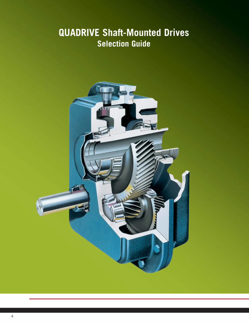
4
QUADRIVE Shaft-Mounted DrivesSelection Guide
© Rexnord Industries, LLC, 1979, 2006. (371-110) 9
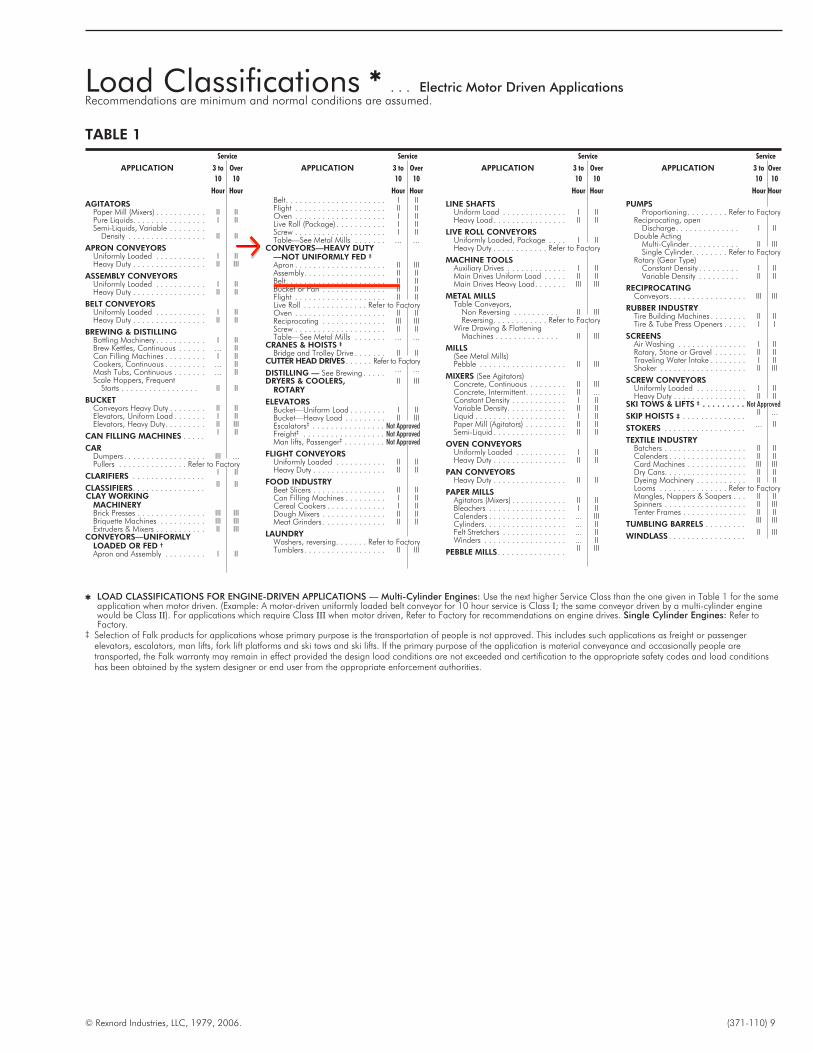
Load Classifications !. . . Electric Motor Driven Applications
Recommendations are minimum and normal conditions are assumed.
Service
APPLICATION 3 to Over
10 10
Hour Hour
AGITATORSPaper Mill (Mixers) . . . . . . . . . . . II IIPure Liquids. . . . . . . . . . . . . . . . I IISemi-Liquids, Variable . . . . . . . .
Density . . . . . . . . . . . . . . . . . II II
APRON CONVEYORSUniformly Loaded . . . . . . . . . . . I IIHeavy Duty . . . . . . . . . . . . . . . . II III
ASSEMBLY CONVEYORSUniformly Loaded . . . . . . . . . . . I IIHeavy Duty . . . . . . . . . . . . . . . . II II
BELT CONVEYORSUniformly Loaded . . . . . . . . . . . I IIHeavy Duty . . . . . . . . . . . . . . . . II II
BREWING & DISTILLINGBottling Machinery . . . . . . . . . . . I IIBrew Kettles, Continuous . . . . . . ... IICan Filling Machines . . . . . . . . . I IICookers, Continuous . . . . . . . . . ... IIMash Tubs, Continuous . . . . . . . ... IIScale Hoppers, Frequent
Starts . . . . . . . . . . . . . . . . . II II
BUCKETConveyors Heavy Duty . . . . . . . . II IIElevators, Uniform Load . . . . . . . I IIElevators, Heavy Duty. . . . . . . . . II III
CAN FILLING MACHINES . . . . . I II
CARDumpers . . . . . . . . . . . . . . . . . . III ...Pullers . . . . . . . . . . . . . . . Refer to Factory
CLARIFIERS . . . . . . . . . . . . . . . . I II
CLASSIFIERS. . . . . . . . . . . . . . . . II II
CLAY WORKINGMACHINERYBrick Presses . . . . . . . . . . . . . . . III IIIBriquette Machines . . . . . . . . . . III IIIExtruders & Mixers . . . . . . . . . . . II III
CONVEYORS—UNIFORMLYLOADED OR FED †
Apron and Assembly . . . . . . . . . I II
Service
APPLICATION 3 to Over
10 10
Hour HourBelt. . . . . . . . . . . . . . . . . . . . . . I IIFlight . . . . . . . . . . . . . . . . . . . . II IIOven . . . . . . . . . . . . . . . . . . . . I IILive Roll (Package) . . . . . . . . . . . I IIScrew . . . . . . . . . . . . . . . . . . . . I IITable—See Metal Mills . . . . . . . ... ...
CONVEYORS—HEAVY DUTY—NOT UNIFORMLY FED ‡
Apron . . . . . . . . . . . . . . . . . . . . II IIIAssembly. . . . . . . . . . . . . . . . . . II IIBelt. . . . . . . . . . . . . . . . . . . . . . II IIBucket or Pan . . . . . . . . . . . . . . II IIFlight . . . . . . . . . . . . . . . . . . . . II IILive Roll . . . . . . . . . . . . . . Refer to FactoryOven . . . . . . . . . . . . . . . . . . . . II IIReciprocating . . . . . . . . . . . . . . III IIIScrew . . . . . . . . . . . . . . . . . . . . II IITable—See Metal Mills . . . . . . . ... ...
CRANES & HOISTS ‡
Bridge and Trolley Drive . . . . . . . II IICUTTER HEAD DRIVES . . . . . . Refer to Factory
DISTILLING — See Brewing . . . . . ... ...
DRYERS & COOLERS,ROTARY
II III
ELEVATORSBucket—Unifarm Load . . . . . . . . I IIBucket—Heavy Load . . . . . . . . . II IIIEscalators‡ . . . . . . . . . . . . . . . . Not ApprovedFreight‡ . . . . . . . . . . . . . . . . . . Not ApprovedMan lifts, Passenger‡ . . . . . . . . . Not Approved
FLIGHT CONVEYORSUniformly Loaded . . . . . . . . . . . II IIHeavy Duty . . . . . . . . . . . . . . . . II II
FOOD INDUSTRYBeet Slicers . . . . . . . . . . . . . . . . II IICan Filling Machines . . . . . . . . . I IICereal Cookers . . . . . . . . . . . . . I IIDough Mixers . . . . . . . . . . . . . . II IIMeat Grinders . . . . . . . . . . . . . . II ll
LAUNDRYWashers, reversing. . . . . . . Refer to FactoryTumblers. . . . . . . . . . . . . . . . . . II III
Service
APPLICATION 3 to Over
10 10
Hour Hour
LINE SHAFTSUniform Load . . . . . . . . . . . . . . I IIHeavy Load. . . . . . . . . . . . . . . . II II
LIVE ROLL CONVEYORSUniformly Loaded, Package . . . . I IIHeavy Duty . . . . . . . . . . . . Refer to Factory
MACHINE TOOLSAuxiliary Drives . . . . . . . . . . . . . I IIMain Drives Uniform Load . . . . . II IIMain Drives Heavy Load. . . . . . . III III
METAL MILLSTable Conveyors,
Non Reversing . . . . . . . . . . II IIIReversing. . . . . . . . . . . . Refer to Factory
Wire Drawing & FlatteningMachines . . . . . . . . . . . . . . II III
MILLS(See Metal Mills)Pebble . . . . . . . . . . . . . . . . . . . II III
MIXERS (See Agitators)Concrete, Continuous . . . . . . . . II IIIConcrete, Intermittent. . . . . . . . . II ...Constant Density . . . . . . . . . . . . I IIVariable Density. . . . . . . . . . . . . II IILiquid . . . . . . . . . . . . . . . . . . . . I IIPaper Mill (Agitators) . . . . . . . . . II IISemi-Liquid . . . . . . . . . . . . . . . . II II
OVEN CONVEYORSUniformly Loaded . . . . . . . . . . . I IIHeavy Duty . . . . . . . . . . . . . . . . II II
PAN CONVEYORSHeavy Duty . . . . . . . . . . . . . . . . II II
PAPER MILLSAgitators (Mixers) . . . . . . . . . . . . II IIBleachers . . . . . . . . . . . . . . . . . I IICalenders . . . . . . . . . . . . . . . . . ... IIICylinders. . . . . . . . . . . . . . . . . . ... IIFelt Stretchers . . . . . . . . . . . . . . ... IIWinders . . . . . . . . . . . . . . . . . . ... II
PEBBLE MILLS . . . . . . . . . . . . . . . II III
Service
APPLICATION 3 to Over
10 10
Hour Hour
PUMPSProportioning. . . . . . . . . Refer to Factory
Reciprocating, openDischarge. . . . . . . . . . . . . . I II
Double ActingMulti-Cylinder . . . . . . . . . . . II IIISingle Cylinder. . . . . . . . Refer to Factory
Rotary (Gear Type)Constant Density . . . . . . . . . I IIVariable Density . . . . . . . . . II II
RECIPROCATINGConveyors. . . . . . . . . . . . . . . . . III III
RUBBER INDUSTRYTire Building Machines . . . . . . . . II IITire & Tube Press Openers . . . . . I I
SCREENSAir Washing . . . . . . . . . . . . . . . I IIRotary, Stone or Gravel . . . . . . . II IITraveling Water Intake . . . . . . . . I IIShaker . . . . . . . . . . . . . . . . . . . II III
SCREW CONVEYORSUniformly Loaded . . . . . . . . . . . I IIHeavy Duty . . . . . . . . . . . . . . . . II II
SKI TOWS & LIFTS ‡ . . . . . . . . . Not Approved
SKIP HOISTS ‡ . . . . . . . . . . . . . . II ...
STOKERS . . . . . . . . . . . . . . . . . . ... II
TEXTILE INDUSTRYBatchers . . . . . . . . . . . . . . . . . . II IICalenders . . . . . . . . . . . . . . . . . II IICard Machines . . . . . . . . . . . . . III IIIDry Cans. . . . . . . . . . . . . . . . . . II IIDyeing Machinery . . . . . . . . . . . II IILooms . . . . . . . . . . . . . . . Refer to FactoryMangles, Nappers & Soapers . . . II IISpinners . . . . . . . . . . . . . . . . . . II IIITenter Frames . . . . . . . . . . . . . . II II
TUMBLING BARRELS . . . . . . . . . III III
WINDLASS . . . . . . . . . . . . . . . . . II III
TABLE 1
! LOAD CLASSIFICATIONS FOR ENGINE-DRIVEN APPLICATIONS — Multi-Cylinder Engines: Use the next higher Service Class than the one given in Table 1 for the sameapplication when motor driven. (Example: A motor-driven uniformly loaded belt conveyor for 10 hour service is Class I; the same conveyor driven by a multi-cylinder enginewould be Class II). For applications which require Class III when motor driven, Refer to Factory for recommendations on engine drives. Single Cylinder Engines: Refer toFactory.
‡ Selection of Falk products for applications whose primary purpose is the transportation of people is not approved. This includes such applications as freight or passengerelevators, escalators, man lifts, fork lift platforms and ski tows and ski lifts. If the primary purpose of the application is material conveyance and occasionally people aretransported, the Falk warranty may remain in effect provided the design load conditions are not exceeded and certification to the appropriate safety codes and load conditionshas been obtained by the system designer or end user from the appropriate enforcement authorities.

© Rexnord Industries, LLC, 1979, 2006. (371-110) 11
Class II Selections for " Shaft (JR) and Flange (JF) Mounted Drives — Sizes 5107 thru 5608Screw Conveyor (JSC) Drives — Sizes 5107 thru 5407
TABLE 3
HP Outputrpm
DriveSize
MinH.S.S.
SheavePitchDia †
1/4
350-191 5107J_05 1.7190-126 5107J_09 1.7125-71 5107J_14 1.7
70-5 5107J_25 1.7
1/3
350-191 5107J_05 1.7190-126 5107J_09 1.7125-71 5107J_14 1.7
70-6 5107J_25 1.95 5115J_25 1.9
1/2
350-191 5107J_05 1.7190-126 5107J_09 1.7125-71 5107J_14 1.7
70-9 5107J_25 1.98-5 5115J_25 2.4
3/4
350-191 5107J_05 1.7190-126 5107J_09 1.7125-71 5107J_14 1.770-13 5107J_25 2.012-7 5115J_25 2.66-5 5203J_25 4.0
1
350-191 5107J_05 1.7190-126 5107J_09 1.7125-71 5107J_14 1.770-17 5107J_25 2.116-10 5115J_25 2.4
9-6 5203J_25 4.05 5207J_25 5.0
1-1/2
350-191 5107J_05 1.7190-126 5107J_09 1.7125-71 5107J_14 1.770-26 5107J_25 2.025-14 5115J_25 2.613-9 5203J_25 4.08-6 5207J_25 5.05 5215J_25 6.0
2
350-191 5107J_05 1.7190-126 5107J_09 1.7125-71 5107J_14 1.770-34 5107J_25 2.033-19 5115J_25 2.518-12 5203J_25 4.011-8 5207J_25 5.07-5 5215J_25 6.0
3
350-191 5107J_05 1.7190-126 5107J_09 1.7125-71 5107J_14 1.770-51 5107J_25 2.150-28 5115J_25 2.627-18 5203J_25 4.017-11 5207J_25 5.010-7 5215J_25 6.07-5 5307J_25 7.0
5
350-191 5107J_05 2.4190-126 5107J_09 1.7125-90 5107J_14 1.789-71 5115J_14 2.070-47 5115J_25 2.646-30 5203J_25 4.029-19 5207J_25 5.018-11 5215J_25 6.010-7 5307J_25 7.06-5 5315J_25 7.0
7-1/2
350-223 5107J_05 3.1222-191 5115J_05 2.2190-132 5107J_09 2.2131-126 5203J_09 4.0125-71 5115J_14 2.0
HP Outputrpm
DriveSize
MinH.S.S.
SheavePitchDia †
7-1/2Cont
70-44 5302J_25 4.043-28 5207J_25 5.027-17 5215J_25 6.016-11 5307J_25 7.010-8 5315J_25 7.07-6 5407J_25 7.05 5415J_25 8.0
10
350-297 5107J_05 3.2296-191 5115J_05 3.5190-177 5107J_09 2.4176-126 5115J_09 2.0125-95 5115J_14 2.094-71 5203J_14 4.070-63 5203J_25 4.062-37 5207J_25 5.036-22 5215J_25 6.021-14 5307J_25 7.013-11 5315J_25 7.010-8 5407J_25 7.07-6 5415J_25 8.0
15
350-301 5115J_05 4.1300-251 5115J_05 5.3251-210 5115J_05 7.1209-191 5207J_05 5.0190-153 5115J_09 2.8152-126 5203J_09 5.1125-9089-71
5203J_145207J_14
4.55.0
70-55 5207J_25 5.054-33 5215J_25 6.032-21 5307J_25 7.020-16 5315J_25 7.015-11 5407J_25 7.010-9 5415J_25 8.08-6 5507J_25 8.05 5608J_25 9.5
20
350-300 5115J_05 8.8299-259 5203J_05 12.1258-191 5207J_05 5.0190-146 5203J_09 11.2145-126 5207J_09 5.0125-74 5207J_14 6.573-71 5215J_14 6.070-44 5215J_25 6.043-27 5307J_25 7.026-22 5315J_25 7.021-15 5407J_25 7.014-11 5415J_25 8.010-7 5507J_25 8.06-5 5608J_25 9.5
25
350-321 5207J_05 5.0320-230 5207J_05 6.9229-205 5207J_05 10.5205-191 5215J_05 6.0190-126 5207J_09 7.3125-96 5207J_14 7.695-71 5215J_14 6.070-55 5215J_25 6.054-34 5307J_25 7.033-27 5315J_25 7.026-18 5407J_25 7.017-14 5415J_25 8.013-9 5507J_25 8.08-6 5608J_25 9.5
HP Outputrpm
DriveSize
MinH.S.S.
SheavePitchDia †
30
350-301 5207_J05 6.7300-260 5207J_05 11.9259-191 5215J_05 6.0190-150 5207J_09 9.2149-126 5215J_09 6.0125-71 5215J_14 6.070-66 5215J_25 6.065-41 5307J_25 7.040-32 5315J_25 7.031-22 5407J_25 7.021-17 5415J_25 8.016-11 5507J_25 8.010-7 5608J_25 9.5
40
350-225 5215J_05 7.0224-191 5307J_05 7.0270-191 5307J_05 7.0190-126 5215J_09 6.0125-88 5215J_14 ‡ 7.787-71 5307J_14 7.070-54 5307J_25 7.053-43 5315J_25 7.042-29 5407J_25 7.028-22 5415J_25 8.021-14 5507J_25 8.013-10 5608J_25 9.5
50
350-300 5215J_05 8.0300-191 5307J_05 7.0190-126 5215J_09 ‡ 8.7125-110 5215J_14 ‡ 9.6109-8887-71
5307J_14 ‡
5307J_149.77.0
70-68 5307J_25 ‡ 7.067-54 5315J_25 ‡ 7.053-36 5407J_25 ‡ 7.035-28 5415J_25 8.027-18 5507J_25 8.017-12 5608J_25 9.5
60
350-301 5307J_05 7.0300-191 5307J_05 10.6190-126 5315J_09 ‡ 7.0190-176 5307J_09! 6.3175-155 5307J_09 ‡ 10.1155-126 5307J_09 ‡ 15.7125-81 5307J_14 ‡ 8.680-71 5315J_14 ‡ 10.070-65 5315J_25 ‡ 7.064-43 5407J_25 ‡ 7.042-33 5415J_25 ‡ 8.032-21 5507J_25 9.620-15 5608J_25 9.5
75
350-301 5307J_05 8.1300-251250-225
5307J_055307J_05
11.916.8
224-191 5315J_05 8.2190-166 5307J_09! 13.8165-126 5315J_09! 8.9125-102 5307J_14! 7.7101-81 5315J_14! 12.380-71 5407J_14 ‡ 7.070-55 5407J_25 ‡ 7.054-41 5415J_25 ‡ 7.040-27 5507J_25 8.026-18 5608J_25 9.5
HP Outputrpm
DriveSize
MinH.S.S.
SheavePitchDia †
100
350-296 5315J_05 ‡ 9.6295-251 5315J_05 10.6250-221 5315J_05 14.5220-166 5315J_09! 11.3165-141 5315J_09! 16.5220-126 5407J_05 9.4125-117 5315J_14! 13.9116-7776-71
5407J_14!5415J_14
7.09.5
70-55 5415J_25! 8.054-35 5507J_25 ‡ 8.034-24 5608J_25 9.5
125
350-311 5407J_05 ‡ 7.4310-181 5407J_05 ‡ 12.7180-156 5407J_05 10.9155-136 5407J_05 13.6135-126 5407J_05 15.7125-96 5407J_14! 7.095-71 5415J_14! 8.070-67 5415J_25! 8.066-44 5507J_25‡ 8.043-30 5608J_25 ‡ 9.9
150
350-301 5407J_05 ‡ 9.2300-221 5407J_05 ‡ 12.5220-176 5407J_05 ‡ 17.4175-156 5415J_05‡ 17.4155-146 5415J_05 ‡ 18.6145-136 5415J_05 ‡ 20.0135-126 5415J_05 ‡ 21.6125-84 5415J_14! 8.083-71 5507J_14! 8.070-53 5507J_25! 8.052-36 5608J_25! 9.9
200
350-271 5407J_05! 13.2270-231 5407J_05! 17.8230-176 5415J_05 ‡ 20.7175-166 5415J_05 ‡ 23.2165-156 5415J_05! 21.8155-71 5507J_14! 8.170-48 5608J_25! 9.5
" Horizontal Drives – Selections shown in bold type require cooling as indicated by footnotes ‡ and ! below. Refer to Engineering 377-114 for maximum output speeds.Vertical Drives – Make selection from Table 2, 3, or 4 and then refer to Engineering 377-114 to determine drive speed limits with and without cooling.
† Values are for V-Belt drives and load applied one shaft diameter from seal cage or fan if so equipped. For minimum sheave diameters for other axial locations, refer to loadlocation factor table on Page 15. Multiply values by 0.66 when using timing belt or chain drives.
‡ Shaft driven fan required.! Electric fan required.

Stop Switch
MATERIAL CONTROL, INC.197 POPLAR PL UNIT 3P.O. BOX 308NORTH AURORA, IL 60542-0308
800-926-0376 630-892-427 FAX 630-892-4931
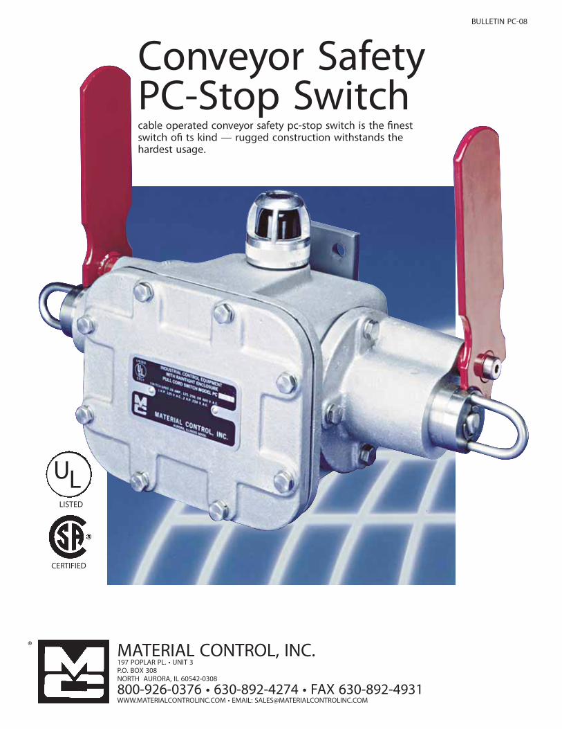
BULLETIN PC-08
Conveyor SafetyPC-Stop Switchcable operated conveyor safety pc-stop switch is the !nestswitch o! ts kind — rugged construction withstands thehardest usage.
ULLISTED
CERTIFIED
®
WWW.MATERIALCONTROLINC.COM EMAIL: [email protected]
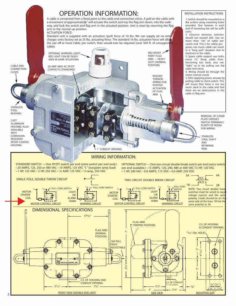
OPERATION INFORMATION:A cable is connected from a !xed point to the cable end connection clevis. A pull on the cable witha movement of approximately1/2" will actuate the switch and trip the "ag arm down, into the walk-way, and lock the switch and "ag arm in the actuated position. Unit is reset by returning the "agarm to the normal up position.ACTUATION FORCE:Standard unit is supplied with an actuation (pull) force of 16 lbs. We can supply (at no extracharge) units factory set at 25 lbs. actuating force. The standard 16 lbs. actuation force will allowthe use o# ar more cable, per switch, than would ever be required (over 500 ft. of unsupportedcable).
INSTALLATION INSTRUCTIONS
1. Switch should be mounted on a"at surface using mounting holesprovided. One fastener in eachend of mounting bar will be su$-cient.2. Distance between switchesshould not exceed 200'. Use nomore than 100' of cable perswitch end. This is for safety pur-poses, too much cable can resultin a “long pull” situation due toslackness in the cable.3. Space cable support eye boltsevery 10'. Keep cable frombecoming too slack, also not“tight” as to be pulling out thecable end clevis.4. Wiring should be through themotor control circuit.5. After applying power, actuate bypulling cable to check switch. Thiswill insure that there is not toomuch slack in the cable and thatthere are no obstructions in thecable or "ag arm.
CABLE ENDCONNECTIONCLEVIS
STAINLESSSTEELBUSHING
20 AMP 480V AC SP/DTCONTACTS (STANDARD)
OPTIONAL WARNING LIGHT:RED LIGHT CAN BE EASILYSEEN IN DARK SITUATIONS
RED EPOXYPAINT FLAGARM — HEAVYDUTY (NORMALPOSITION)
RUGGEDTORSIONSPRING FORPOSITIVEACTUATIONOF FLAGARM
REMOVAL OF COVERPLATE EXPOSESSWITCH TERMINALS.PLENTY OF ROOMFOR WIRING
STAINLESSSTEEL SHAFTANDRETAININGRING1" CONDUIT OPENING
CASTALUMINUMHOUSING ALSOAVAILABLEWITHCORROSIONRESISTANTEPOXY COATEDHOUSING
WIRING INFORMATION:
DIMENSIONAL SPECIFICATIONS
STANDARD SWITCH —One SP/DT switch per end (extra switch per end avail.)20 AMPS, 125, 250 or 480 VA 10 AMPS, 125 VAC “L” (tungsten lamp load)HP, 125 VAC HP, 250 VAC 1/2 AMP, 125 VDC 1/4 amp, 250 VDC
OPTIONAL SWITCH—One two circuit double break switch per end (extra switchper end available. 15 AMPS, 120, 240, 480 or 600 VAC 1/2 HP, 120 VAC1 HP, 240 VA 0.8 AMPS, 115 VD 0.4 AMP, 230 VDC
SINGLE POLE, DOUBLE THROW CIRCUIT TWO CIRCUIT, DOUBLE BREAK CIRCUIT3A
1B
4A
2B
N.CN.O
NOTE: Two circuit double breakswitches must be wired to equalvoltage sources and the samepolarity. Loads should be on thesame side of the lines. 1B has thesame polarity as 3A.
MOTORSTARTER
COIL
C/L OF HOUSING ANDCONDUIT OPENING
FLAG ARM(TRIPPED POSITION) C/L OF HOUSING
& CONDUIT OPENING
13/32" DIA. HOLES
529/32"
37/16" 73/4" 31/4"
3/4"
11/4" 11/4"27/8"3/8"
3/4" 3/4"
5"
23/4"
415 / 1
6"
7"
3"3"
FLAG ARM(NORMALPOSITION)
16# PULLFIELDADJUSTABLE
C/L OF CONDUIT1"-111/2 N.P.T.
MOTOR CONTROL CIRCUIT
FRONT VIEW (DOUBLE END UNIT) SIDE VIEW MOUNTING BAR
WARNING CIRCUIT
LIGHTOR
ALARMHORN
L1 PULL CORD SWITCH PULL CORD SWITCHL2L1 L2
cn.c
MOTORSTARTER
COIL
MOTOR CONTROL CIRCUIT
L1 PULL CORD SWITCHL2
3a4a
cn.o
WARNING CIRCUIT
LIGHTOR
ALARMHORN
PULL CORDSWITCH
L1 L2
1b2b
2.

TORSION SPRINGSRight or left hand replace-ment torsion springs for allPC switches. PC-31 RH or LH
CABLE SUPPORT EYE BOLTSPlated 1/2" N.C. thread - twonuts and one lock-washerincluded. PC-27
CABLE END FITTINGSForged steel saddle and steelU-bolt. Cadmium plated boltsand nuts. PC-28
CONDUIT PLUG1" metal conduit plug. PC-29
PC MOUNTINGBRACKET. PC-30
CABLE WITH ORANGEPROTECTIVE COATING3/32 7x7 preformed galva-nized aircraft cable 3/16" O.D.Vinyl coated. PC-25Nylon coated. PC-26
ACCESSORIES:LEFT HAND
6"
21/2"
11/2"
415 /
16"
7/16" DIA.HOLES
1/2"
2"
5"
1"
RIGHT HAND
HAZARDOUS LOCATIONS:Explosion proof units meet NEMA 7 — class 1, Groups C and D• NEMA 9 — class II, Groups E, F and G for hazardous locations. Add“X” to model number, NO ADDITIONAL CHARGE.
PENNSYLVANIA B.O.T.E. APPROVED:PCD-27-B.O.T.E.
REMOTE OR DARK LOCATIONS:Use or red warning light in dark and remote areas (requires two microswitches per end of housing). 125V AC.NOTE: Available in rain tight, dust tight and explosion proof.Add prefix “L” to model number.
CORROSIVE LOCATIONS:Epoxy coated switches with standard flag arms and plated torsionsprings. Please add “EPOXY” to model number.
SPECIAL APPLICATION OPTIONS:
1-SINGLE POLE:double throw micro switchPCL-1S . . . . . . . . . .LEFT HANDPCR-1S . . . . . . . . RIGHT HANDTYPICAL USE:Emergency shutdown of convey-ors or other machinery.AVAILABLE OPTIONS:• Hazardous locations• Corrosive locations
1-TWO CIRCUIT:double throw micro switch forD.C circuitsPCL-1T . . . . . . . . . .LEFT HANDPCR-1T . . . . . . . . RIGHT HANDTYPICAL USE:Emergency shutdown of convey-ors and other machinery.AVAILABLE OPTIONS:• Hazardous locations• Corrosive locations
2-SINGLE POLE:Double throw micro switchPCL-2S . . . . . . . . . .LEFT HANDPCR-2S . . . . . . . . RIGHT HANDTYPICAL USE:Emergency shutdown of convey-ors or other machinery — withalarm or computer interfacecapability.AVAILABLE OPTIONS:• Hazardous locations• Corrosive locations• Remote or dark locations
2-TWO CIRCUIT:Double throw micro switch forD.C circuitsPCL-2T . . . . . . . . . .LEFT HANDPCR-2T . . . . . . . .RIGHT HANDTYPICAL USE:Emergency shutdown of convey-ors or other machinery — withalarm or computer interface cap.AVAILABLE OPTIONS:• Hazardous locations• Corrosive locations• Remote or dark locations
1-SINGLE POLE:double throw micro switch ateach endPCD-2S . . . . . DOUBLE ENDEDTYPICAL USE:Emergency shutdown of convey-ors and other machinery.AVAILABLE OPTIONS:• Hazardous locations• Corrosive locations• Remote or dark locations
1-TWO CIRCUIT:double throw micro switch ateach end for D.C circuitsPCD-2T . . . . . DOUBLE ENDEDTYPICAL USE:Emergency shutdown of convey-ors or other machinery.AVAILABLE OPTIONS:• Hazardous locations• Corrosive locations• Remote or dark locations• Pennsylvania B.O.T.E. approved
2-SINGLE POLE:Double throw micro switches ateach endPCD-4S . . . . . DOUBLE ENDEDTYPICAL USE:Emergency shutdown of convey-ors or other machinery — withalarm or computer interfacecapability.AVAILABLE OPTIONS:• Hazardous locations• Corrosive locations• Remote or dark locations
2-TWO CIRCUIT:Double throw micro switches ateach end for D.C circuitsPCD-4T . . . . . DOUBLE ENDEDTYPICAL USE:Emergency shutdown of convey-ors or other machinery — withalarm or computer interfacecapabilityAVAILABLE OPTIONS:• Hazardous locations• Corrosive locations• Remote or dark locationsMODELS
PCL-1SPCR-1SPCL-2SPCR-2S
MODELSPCL-1TPCR-1TPCL-2TPCR-2T
MODELSPCD-2SPCD-4S
MODELSPCD-2TPCD-4T
SELECTION AND MODEL INFORMATION
TECHNICAL INFORMATION:Enclosure sealed for outside applications • Standard unit meetsNEMA 1,3,4,4X and 12 requirements • Housing: cast aluminum
• Flag arm: steel with red epoxy paint coating.
MODEL 16 BELT ALIGNMENT SWITCH
200' MAXIMUM 200' MAXIMUM
PCL-1S
PCR-1SLEFTHANDPCL-1SRIGHT
HANDPCR-1S
PCD-2S
3.
SEE PRICE SHEET FOR PRICES
xx
Zero MotionSpeed Switch

SCP1000 Presettable Speed Switch
Single or double relay set point protection.1-100 and 10-1000 RPM set point ranges (others available).Built-in start delay and signal loss protection.ETL® approved to applicable UL and CSA standards.Explosionproof housing is dirt, dust, grease and waterproof.Switch selectable overspeed or underspeed sensing.Dial in set point adjustment with digital accuracy.
DescriptionSCP series presettable speed switches are self-contained shaft rotation monitoring systems providing one or two individuallyadjustable relay set points. They are ideal for use in hazardous and wet locations where speed indication for alarm or machineryshutdown is critical for safe operation. SCP series switches are an excellent choice for overspeed and/or underspeed protection ofbucket elevators, fans/blowers, screw conveyors, rotary airlocks or virtually any rotating shaft. SCP series switches are o!ered asstandard in two con"gurations: a single relay output (SCP-1000) . While many applications requireonly one set point (SCP-1000). If the shaft continues to slow down and reaches the second set point, the primary process can be wired for shutdown, maintaining the e#ciency and safety of operations by preventing machine damage, product waste and costlydowntime. SCP series switches eature visual set point adjustment via rotary dials for ease and accuracy, and all calibration can be done with the machinery at rest
.
Principle of OperationSCP series switches have an internal Hall-E!ect sensor and are supplied with a shaft-end mounted Pulser Disc (or optional split colla rPulser Wrap), which generates an alternating magnetic "eld picked up by the SCP's large-gap, non-contact sensor. The SCP decodesthis frequency signal to determine shaft speed, and compares it to the pre-adjusted set point(s). The relay output(s) can then beused for equipment shutdown or to provide an alarm, assuring machine protection and process integrity. SCP series speed switchesare fail-safe; any malfunction during operation will de-energize the control circuit.
Product Information
255 Pulser DiscStock No. 700-000200
Dimensional Drawings SCP Series Speed Switches
6111 Blue Circle Drive Minnetonka, MN 55343Phone: 952-930-0100 Fax: 952-930-0130 ISO9001:2000 Certified
Free Catalog and Application Assistance
1-800-328-6170Visit Us Online:
www.electro-sensors.com
Mounting BracketSCP Series Speed Switch

SCP1000 Presettable Speed Switch
Specifications SCP 1000 Input PowerVoltage.................................................. 115Vac, 60 Hz std; 230 Vac,
12 Vdc or 24 Vdc optional
Input SignalType ........................................................ Open Collector/LogicAmplitude .......................................... 5V Pull-Up, 4.7 K OhmsImpedance ........................................ 2200 Ohms to 15VFrequency Range.......................... 0-20,000 Hz
Set Point DataNumber Available ........................ One or TwoMode ......................................................Selectable — Overspeed
or UnderspeedAdjustments .................................... Rotary Switches (Tens and
Ones digit)Hysteresis .......................................... 6%Range .................................................... 1 - 100 rpm, 10 - 1000 rpmAccuracy .............................................. 0.005% at bottom of range
0.25% at midrange0.5% at top of range
Relay Contact Rating ................ SCP-1000: Isolated, 5A250 Vac, 30 Vdc Resistive
Contact Arrangement .............. SCP-1000: One Form C, D.P.D.T. SCP-2000: Two Form C, S.P.D.T.
Start Delay.......................................... 10 seconds (!xed)
Physical/EnvironmentalHousing and Cover...................... Cast Aluminum, C.S.A. & FM
Approved. Meets NEMA 1, 3, 12, 13 and NEMA 7, 9. Hazardous location. U.L. rated: Class I Group D, Class II Groups E, F, G. NEMA 4
ElectricalGap Distance .................................... 3/8" ± 1/8"255 Pulser Disc ................................ Nylon® 12, 4” dia., 16 alternating
magnetic polesMounting ............................................ Bracket, 1-inch NPT Conduit
OpeningOperating Temperature .......... -40° C to +60° C*
Available OptionsSplit Collar Pulser Wrap for when end of shaft is inaccessible.Wraps available in the following materials: ° PVC° Aluminum ° Stainless SteelEZ-SCP Easy Mount Bracket Assembly (!gure 3).PTU-1000 Test Unit - used with SCP switches* to verify shaft speed or to simulate any unwanted condition for test purposes.* PTU Interface not standard on the SCP1000
Special Factory Options to modify standard functions of SCP series speed switches:
° Increased or decreased start delay interval.° No start delay.° Lower or higher set point ranges available.*° Increased set point range.° Calibration in percent of speed.° Signal loss protection inactivation in overspeed mode.
SCP Series Switch InstallationSCP series speed switches are supplied with aneasily adjustable mounting bracket assembly.The speed switch must be installed allowing thecenterline of the magnets to pass in front of thecenter of the sensing head during rotation. Thegap distance between the speed switch and discor wrap (dimension A in !gures 1 & 2) is 3/8” ±1/8”. When using a standard 4" Pulser Disc, thecenter of the magnetized area of the disc(dimension B in !gure 1) is 1-3/4" from the center hole of the disc.
ES-345 Rev E* Contact factory for higher temperature ranges. Speci!cations subject to change without notice.
6111 Blue Circle Drive Minnetonka, MN 55343Phone: 952-930-0100 Fax: 952-930-0130 ISO9001:2000 Certified
Free Catalog and Application Assistance
1-800-328-6170Visit Us Online:
www.electro-sensors.com
SCP SeriesSwitch andWrapFigure 2
Optional EZ-SCP Easy Mount Bracket AssemblyFigure 3
* Consult factory for further options.

Product Information
6111 Blue Circle DriveMinnetonka, MN 55343Phone: 952-930-0100Fax: 952-930-0130ISO 9001:2000 Certified
Free Catalog and Application Assistance
1-800-328-6170Visit us online
www.electro-sensors.comSuperior · Systems · Solutions
Split Collar Pulser WrapsSplit Collar Pulser WrapsSplit Collar Pulser WrapsSplit Collar Pulser WrapsSplit Collar Pulser WrapsCustom made for your application, built to yourspecifications
No machinery tear-down required for mountingFive types of wraps fit most applicationsCustom number of pulses per revolutionPVC, aluminum, or stainless steelHigh temperature wraps available
DescriptionPulser Wraps are PVC, aluminum, or stainless steel split collars with magnets mounted on the outside circumference. Themagnets serve as targets for Hall-E!ect and Magnetoresistive sensors that switch when exposed to magnetic "elds. All wraps a recustom machined to the diameter of the monitored shaft and are split into halves. This splitting process allows the wrap toclamp tightly onto the shaft without tearing down any equipment to install them. The halves are secured around the shaft withrecessed Allen-head socket screws supplied. Pulser Wraps provide magnetic targets that are strong enough to allow large gapdistances (up to 1/2 -inch) between the wrap and the sensor. The wrap and sensor system forgives slight misalignment of thesensor, machinery vibration, dirty, wet, or greasy environments, and shaft end-play.
Special WrapsWraps purchased for use with s tandard Electro-Sensors systems are typically provided with 16 magnets of alte rnating polarity.Using a standard Hall-E!ect sensing system, this provides 8 pulses per revolution from the sensor. Special wraps can be provi dedto suit particular application requirements. This often includes adding magnets to the wraps to increase the n umber of pulses perrevolution generated by the sensing system. Adding magnets will usually require an increase in the outside diameter of the wra p.Standard and miniature wraps are t ypically selected when more magnets are required bec ause the magnets may be addedwithout large increases in the ouside diameter, particularly if the 1/4" diameter magnets are used. Wraps can be manufac-tured from PVC, aluminum, or stainless steel, and have the option of a keyway where required. SSSSSttttteel inseeel inseeel inseeel inseeel inserrrrrttttts cs cs cs cs c an bean bean bean bean besubssubssubssubssubstttttitutitutitutitutituted fed fed fed fed for magor magor magor magor magnetnetnetnetnets s s s s when using prwhen using prwhen using prwhen using prwhen using pr oooooximitximitximitximitximity or y or y or y or y or mag mag mag mag mag sensors. sensors. sensors. sensors. sensors. An Electro-Sensors Application Specialist can assistin the design of wraps to meet speci"c or special needs.
O.D. = I.D. +3"4" Minimum O.D. 1.50"
Standard Wrap
Dimensional Drawing
ES-102 Rev. E
6111 Blue Circle DriveMinnetonka, MN 55343Phone: 952-930-0100Fax: 952-930-0130ISO 9001:2000 Certified
Free Catalog and Application Assistance
1-800-328-6170Visit us online
www.electro-sensors.comSuperior · Systems · Solutions
Split Collar Pulser Wraps
Speci!cations subject to change without notice.
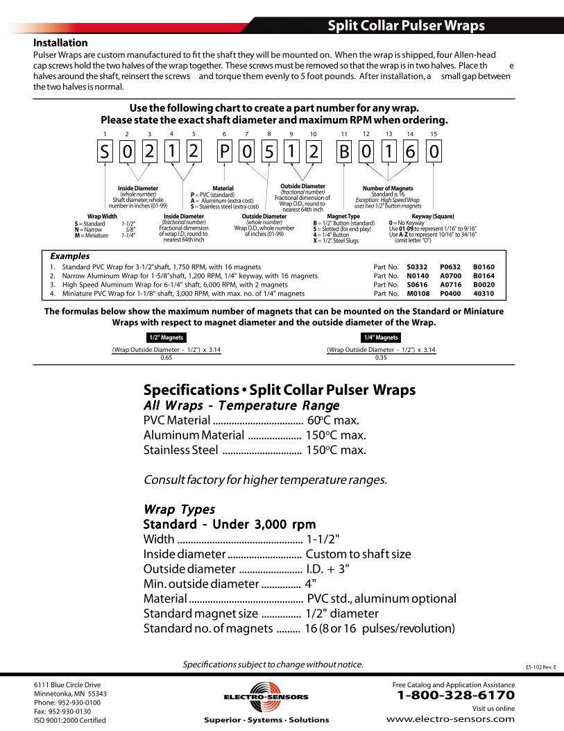
1/2" Magnets
(Wrap Outside Diameter - 1/2") x 3.140.65
1/4" Magnets
(Wrap Outside Diameter - 1/2") x 3.140.35
The formulas below show the maximum number of magnets that can be mounted on the Standard or MiniatureWraps with respect to magnet diameter and the outside diameter of the Wrap.
InstallationPulser Wraps are custom manufactured to !t the shaft they will be mounted on. When the wrap is shipped, four Allen-headcap screws hold the two halves of the wrap together. These screws must be removed so that the wrap is in two halves. Place th ehalves around the shaft, reinsert the screws and torque them evenly to 5 foot pounds. After installation, a small gap betweenthe two halves is normal.
1 2 3 4 5 6 7 8 9 10 11 12 13 14 15
S = Standard 1-1/2"N = Narrow 5/8"M = Miniature 1-1/4"
Wrap Width
Inside Diameter(whole number)
Shaft diameter, wholenumber in inches (01-99)
Inside Diameter(fractional number)
Fractional dimensionof wrap I.D., round to
nearest 64th inch
P = PVC (standard)A = Aluminum (extra cost)S = Stainless steel (extra cost)
Material
Outside Diameter(whole number)
Wrap O.D., whole numberof inches (01-99)
Outside Diameter (fractional number)
Fractional dimension of Wrap O.D., round to
nearest 64th inchMagnet Type
B = 1/2" Button (standard)S = Slotted (for end play)4 = 1/4" ButtonX = 1/2" Steel Slugs
Number of MagnetsStandard is 16
Exception: High Speed Wrap uses two 1/2" button magnets
0 = No KeywayUse 01-09 to represent 1/16" to 9/16"Use A-Z to represent 10/16" to 34/16" (omit letter "O")
Keyway (Square)
Use the following chart to create a part number for any wrap.Please state the exact shaft diameter and maximum RPM when ordering.
Specifications Split Collar Pulser WrapsAll WAll WAll WAll WAll W rrrrraps - Taps - Taps - Taps - Taps - T empeempeempeempeemperrrrraturaturaturaturature Re Re Re Re R angangangangangeeeeePVC Material .................................. 60oC max.Aluminum Material .................... 150oC max.Stainless Steel .............................. 150oC max.
Consult factory for higher temperature ranges.
Wrap TypesWrap TypesWrap TypesWrap TypesWrap TypesStandard - Under 3,000 rpmStandard - Under 3,000 rpmStandard - Under 3,000 rpmStandard - Under 3,000 rpmStandard - Under 3,000 rpmWidth ............................................... 1-1/2"Inside diameter ............................ Custom to shaft sizeOutside diameter ........................ I.D. + 3"Min. outside diameter ............... 4"Material ........................................... PVC std., aluminum optionalStandard magnet size ............... 1/2" diameterStandard no. of magnets ......... 16 (8 or 16 pulses/revolution)
Examples.oN traPstengam 61 htiw ,MPR 057,1 ,tfahs"2/1-3 rof parW CVP dradnatS.1 S0332 P0632 B0160
2. Narrow Aluminum Wrap for 1-5/8"shaft, 1,200 RPM, 1/4" keyway, with 16 magnets Part No. N0140 A0700 B0164.oN traPstengam 2 htiw ,MPR 000,6 ,tfahs "4/1-6 rof parW munimulA deepS hgiH.3 S0616 A0716 B0020
4. Miniature PVC Wrap for 1-1/8" shaft, 3,000 RPM, with max. no. of 1/4" magnets Part No. M0108 P0400 40310
S 0 2 1 2 P 0 5 1 2 B 0 1 6 0

ES345 Rev. D
Features:
· Single or Double Relay Set Point Protection· Positive Visual Set Point Adjustment w/Digital Accuracy· Built-in Start Delay· Switch Selectable Underspeed or Overspeed Sensing· 1-100 and 10-1000 rpm Set Point Ranges· Dustproof, Dirtproof, Greaseproof and Waterproof· ETL® Approved to UL® 508 Standard· Explosion-proof Housing, UL, CSA Approved
Description:The SCP-Series Presettable Machine Switches are com-
plete systems for providing one or two individually adjustablerelay set points, while monitoring a single rotating shaft. TheSCP-Series Switches are ideal for applications where speedindication for alarm and shutdown purposes is critical for safeand efficient operation of your equipment. The SCP-Seriesare the “Installers Choice” for protecting bucket elevators,fans, airlocks, mixers, or virtually any rotating shaft, includingoverspeed sensing requirements.
The SCP-Series Speed Switches are offered with a singlerelay output (Model SCP-1000).
Another control function,commonly used in the grain industry, employs both relays setin the Underspeed Mode. The first relay provides warning of aslowdown, and also permits interlock wiring to shut downauxiliary machinery. If the shaft continues to slow down andreaches the second set point speed, the primary process canbe wired for shutdown to prevent equipment damage andproduct loss.
Both models feature visual set point adjustment for “dial in”ease and accuracy of set point settings. The SCP-SeriesSwitches can be completely adjusted with the machinery atrest. There is no need to run the shaft. Precision digitalcircuitry provides high accuracy, repeatability, and reliability.
The SCP-Series Switches have an internal Hall-EffectSensor which is used to monitor a magnetic target, such asa Pulser Disc or the optional Pulser Wrap, mounted on themonitored shaft. As the Disc or Wrap rotates in front of theHall-Effect Sensor, a digital signal proportional to the speedof the monitored shaft is produced. The signal is used bythe unit’s electronics to determine shaft speed and relay set
SCP Switch and OptionalPulser wrap
Pulser Wrap Pulser Wraps are custom manufactured to fit the shaft they
will be mounted on, When the wrap is shipped, fourhead cap screws hold the two halves of the wrap together.These screws must be removed so that the wrap is in twohalves. Place the halves around the shaft, reinsert the screwsand torque them to 8 foot pounds.

Electro-Sensors, Inc. Presettable Machine Speed Switch. SCP-Series
SCP-Series Installation: Sensing Head and Wrap:The SCP-Series Switches are
supplied with a mounting bracketassembly. The speed switch must beinstalled so the center line of themagnets passes in front of the centerportion of the sensing head as theyrotate.
The gap distance between thespeed switch and the wrap(dimension A in the diagrams) canbe from 1/16-inch to 1/4-inch . Theproper gap distance is achievedby adjusting the position of theSCP-Series Switches using theslots on the mounting bracket.
SCP-Series Calibration:See Figure 3 for Switch Locations
Four Steps to Calibrating the SCP-Series Switches:1. Determine your monitoring requirement. The Model
SCP-1000 provides a single relay set point, while theModel SCP-2000 has two independent relay set points Double Set Point Protection.
2. Determine whether the relay(s) should deenergize whenthe shaft speed drops below the set point speed(Underspeed Operation), or when the shaft speed goesabove the set point speed (Over Speed Protection). Adjustthe Under/Over Speed Selec tion switch(es) to set theSCP-Series Switch in the desired Mode. (See the diagramat right for the switch positions).
3. If the required relay trip point (set point speed) is below100 rpm, set the Set Point Range Selection Switch to the1-100 rpm range. If the relay trip set point is above 100 rpmand below 1000 rpm, select the 10-1000 rpm range.
4. Set the corresponding rotary Set Point switches to thedesired set point RPM. The switches can be set to anynumber from 01-99. A setting of 00 will read as though itwas entered as 01.
Signal Loss Protection:In Underspeed Mode, a loss of sensor signal will be detect-
ed immediately, and the relay(s) will deenergize. In OverspeedMode, the loss of signal will be detected immediately, but theSCP-Series Switch will wait 30-seconds for the signal toresume. This prevents unwanted shutdown when monitoringvery slow-moving shafts. After the 30-seconds have elapsedwith no incoming signal, the relay(s) will deenergize.
Start Delay:A 10-second start delay is built into the SCP-Series
Switches. In Underspeed Mode, the start delay holds therelay(s) in an energized state for 10-seconds, allowing monitored shaft to reach a speed above the set point(s)
Calibration Example: If the Set Point Range SelectionSwitch was set in the 1-100 rpm range, and the desired setpoint speed is 50 rpm, the Set Point switches should be set to50. In the 10-1000 rpm range, the set point is 10-times theswitch setting (i.e. a switch setting of 60 results in a set pointof 600 rpm).Note: Calibration should be done with power to the SCP
turned off. If a change is made to the calibration while power
is on (not recommended), cycle power to the unit. This will
store the new set point, and restart the 10-second start delay.
before monitoring begins. The start delay begins when poweris applied to the SCP-Series Switch. If additional start delaytime is required, an external time delay relay can be used, orconsult the factory for more options.
Special Options:Special options are available from the factory to modify the
standard functions of the SCP-Series Switches. Optionsinclude: Increased or Decreased Start Delay Interval, No StartDelay, Reduced or Enlarged Set Point Hysteresis, Set PointOver 1000 RPM, Calibration in Percent of Speed, and SignalLoss Protection Inactivation in Overspeed Mode.
2
Electro-Sensors, Inc. Presettable Machine Speed Switch- SCP-Series
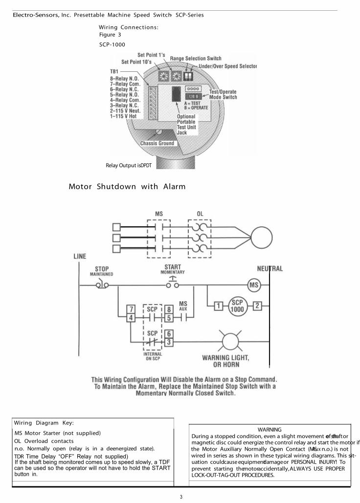
Wiring Connections:Figure 3
SCP-1000
Relay Output is DPDT
Motor Shutdown with Alarm
Wiring Diagram Key:
MS Motor Starter (not supplied)OL Overload contactsn.o. Normally open (relay is in a deenergized state).TDR Time Delay “OFF” Relay not supplied)If the shaft being monitored comes up to speed slowly, a TDFcan be used so the operator will not have to hold the STARTbutton in.
WARNINGDuring a stopped condition, even a slight movement of the shaft ormagnetic disc could energize the control relay and start the motor ifthe Motor Auxiliary Normally Open Contact (MSAux n.o.) is notwired in series as shown in these typical wiring diagrams. This sit-uation couldcause equipmentdamage or PERSONAL INJURY! Toprevent starting themotoraccidentally, ALWAYS USE PROPERLOCK-OUT-TAG-OUT PROCEDURES.
3
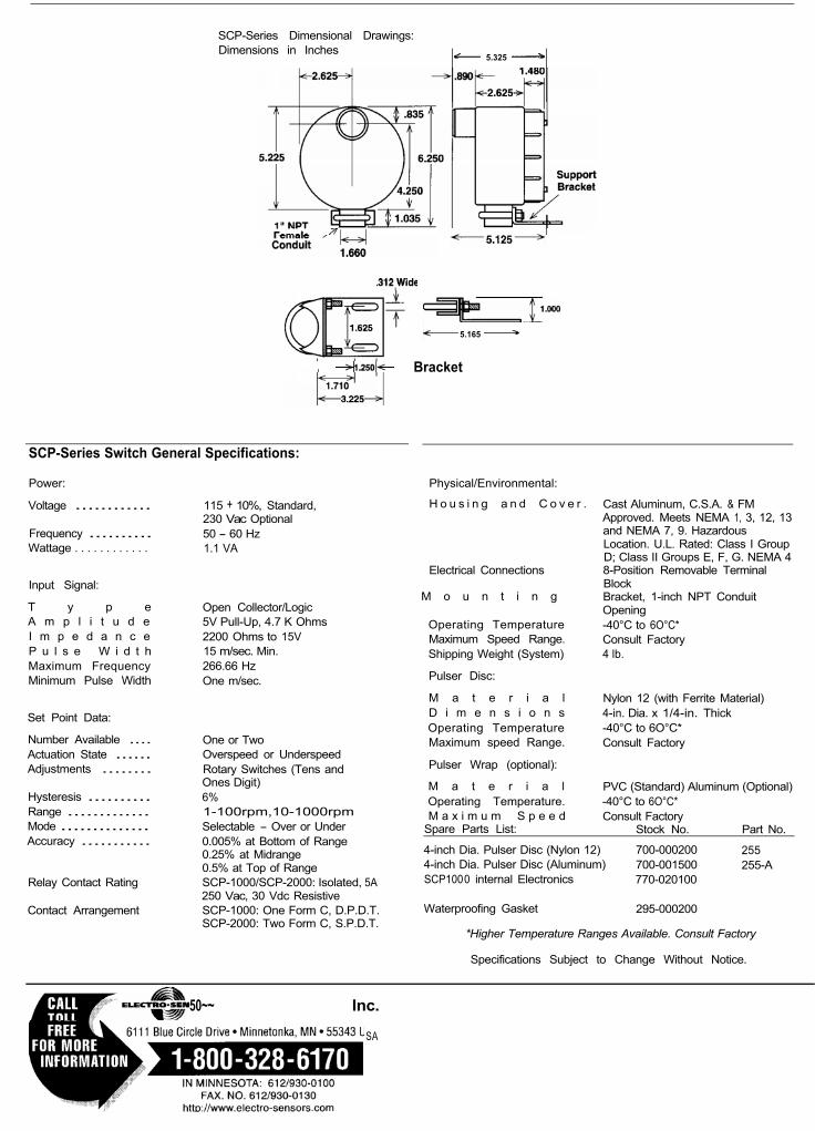
SCP-Series Dimensional Drawings:Dimensions in Inches
5.325
Bracket
5.165
SCP-Series Switch General Specifications:
Power:
Voltage ............
Frequency ..........Wattage . . . . . . . . . . . .
Input Signal:
T y p e Open Collector/LogicA m p l i t u d e 5V Pull-Up, 4.7 K OhmsI m p e d a n c e 2200 Ohms to 15VP u l s e W i d t h 15 m/sec. Min.Maximum Frequency 266.66 HzMinimum Pulse Width One m/sec.
Set Point Data:
Number Available ....Actuation State ......Adjustments ........
Hysteresis ..........Range .............Mode ..............Accuracy ...........
Relay Contact Rating
Contact Arrangement
115 + 10%, Standard,230 Vac Optional50 - 60 Hz1.1 VA
One or TwoOverspeed or UnderspeedRotary Switches (Tens andOnes Digit)6%1-100rpm,10-1000rpmSelectable - Over or Under0.005% at Bottom of Range0.25% at Midrange0.5% at Top of RangeSCP-1000/SCP-2000: Isolated, 5A250 Vac, 30 Vdc ResistiveSCP-1000: One Form C, D.P.D.T.SCP-2000: Two Form C, S.P.D.T.
Physical/Environmental:
H o u s i n g a n d C o v e r .
Electrical Connections
Cast Aluminum, C.S.A. & FMApproved. Meets NEMA 1, 3, 12, 13and NEMA 7, 9. HazardousLocation. U.L. Rated: Class I GroupD; Class II Groups E, F, G. NEMA 48-Position Removable TerminalBlockBracket, 1-inch NPT ConduitOpening-40°C to 6O°C*Consult Factory4 lb.
Nylon 12 (with Ferrite Material)4-in. Dia. x 1/4-in. Thick-40°C to 6O°C*Consult Factory
M o u n t i n g
Operating TemperatureMaximum Speed Range.Shipping Weight (System)
Pulser Disc:
M a t e r i a lD i m e n s i o n sOperating TemperatureMaximum speed Range.
Pulser Wrap (optional):
M a t e r i a l PVC (Standard) Aluminum (Optional)Operating Temperature. -40°C to 6O°C*M a x i m u m S p e e d Consult Factory
Spare Parts List: Stock No. Part No.
4-inch Dia. Pulser Disc (Nylon 12) 700-000200 2554-inch Dia. Pulser Disc (Aluminum) 700-001500 255-ASCP1000 internal Electronics 770-020100
Waterproofing Gasket 295-000200
*Higher Temperature Ranges Available. Consult Factory
Specifications Subject to Change Without Notice.
50~~ Inc.
SA
Data Sheets for Main Components

Serpentix Conveyor Corporation — 9085 Marshal Court, Westminster, Colorado 80031-2920 — USA Toll Free: 1.800.466.7979 | Direct: 303.430.8427 | Fax: 303.430.7337 | serpentixconveyor.com | Email: [email protected]
SERPENTIX CONVEYOR CORP.Pathwinder (Model-P2) Conveyor
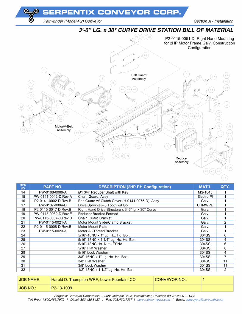
3’-6” LG. x 30° CURVE DRIVE STATION BILL OF MATERIAL Section A - Installation
JOB NAME: Harold D. Thompson WRF, Lower Fountain, CO CONVEYOR NO.: 1
JOB NO.: P2-13-1099
P2-0115-0051-D: Right Hand Mounting for 2HP Motor Frame Galv. Construction
Configuration
ITEM NO. PART NO. DESCRIPTION MAT’L QTY. 1 US Motor
H2P2D 2-HP, 1750 RPM, TEFC, 3-Phase, 60 Hz, 208 230/460 VAC, Frame-Cast Iron 145T, Service Factor-1.15, Insulation-F, Ambient Temp. –40 Degrees C, Mounting - RH Motor Special-
Cast 1
2 5203J25C Helical Speed Reducer - Falk w/ Bushing #BU5203J-1.750 Cast 1 3 MP-35-3-23 2 3/16” Pillow Block Bearing Steel 2 4 Sprocket, No 60 BS 60, 2 3/16” Bore Steel 1 5 Sprocket, No. 60 FB 15, 1 3/4” Bore Steel 1 6 Single Strand Roller Chain-ANSI #60– 83 Pitch x 62.5”Lg. Steel 1 7 Single Strand Roller Chain Connector Link-ANSI #60 Steel 1 8 - blank - - - 9 S180 Aunspach Torque Limiting Sheave Cast 1
10 QD Bushing, No. JA, 7/8” Bore Steel 1 11 QD Sheave, 3V- Ø2.65 - 2 Groove (22 FPM) Cast 1 12 V-Belt, Super HC, No. 3VX-425 Belt 2 13 PW-0108-0001-A Ø2 3/16” Drive Shaft with Keys 416SS 1
Serpentix Conveyor Corporation — 9085 Marshal Court, Westminster, Colorado 80031-2920 — USA Toll Free: 1.800.466.7979 | Direct: 303.430.8427 | Fax: 303.430.7337 | serpentixconveyor.com | Email: [email protected]
SERPENTIX CONVEYOR CORP.Pathwinder (Model-P2) Conveyor
3’-6” LG. x 30° CURVE DRIVE STATION BILL OF MATERIAL Section A - Installation
JOB NAME: Harold D. Thompson WRF, Lower Fountain, CO CONVEYOR NO.: 1
JOB NO.: P2-13-1099
P2-0115-0051-D: Right Hand Mounting for 2HP Motor Frame Galv. Construction
Configuration
Reducer Assembly
Motor/V-Belt Assembly
Belt Guard Assembly
ITEM NO. PART NO. DESCRIPTION (2HP RH Configuration) MAT’L QTY. 14 PW-0108-0009-A Ø1 3/4” Reducer Shaft with Key MS-1045 1 15 PW-0141-0042-D,Rev.A Chain Guard, Assy Electro Pl 1 16 P2-0141-0002-D,Rev.B Belt Guard w/ Clutch Cover (H-0141-0075-D), Assy Galv. 1 17 PW-0107-0004-D Drive Sprocket– 8 Tooth w/Hub UHMWPE 1 18 P2-0115-0017-D,Rev.B Right-Hand Drive Structure x 3’-6” lg. x 30° Curve Galv. 1 19 PW-0115-0062-D,Rev.E Reducer Bracket-Formed Galv. 1 20 PW-0115-0067-D,Rev.D Chain Guard Bracket Galv. 1 21 PW-0115-0021-A Motor Mount Slide/Clamp Bracket Galv. 2 22 P2-0115-0008-D,Rev.B Motor Mount Plate Galv. 1 23 PW-0115-0023-A Motor All-Thread Bracket Galv. 1 24 5/16”-18NC x 1” Lg. Hx. Hd. Bolt 304SS 6 25 5/16”-18NC x 1 1/4” Lg. Hx. Hd. Bolt 304SS 4 26 5/16”-18NC Hx. Nut - ESNA 304SS 6 27 5/16” Flat Washer 304SS 8 28 5/16” Lock Washer 304SS 4 29 3/8”-16NC x 1” Lg. Hx. Hd. Bolt 304SS 7 30 3/8” Flat Washer 304SS 11 31 3/8” Lock Washer 304SS 11 32 1/2”-13NC x 1 1/2” Lg. Hx. Hd. Bolt 304SS 2
Serpentix Conveyor Corporation — 9085 Marshal Court, Westminster, Colorado 80031-2920 — USA Toll Free: 1.800.466.7979 | Direct: 303.430.8427 | Fax: 303.430.7337 | serpentixconveyor.com | Email: [email protected]
SERPENTIX CONVEYOR CORP.Pathwinder (Model-P2) Conveyor
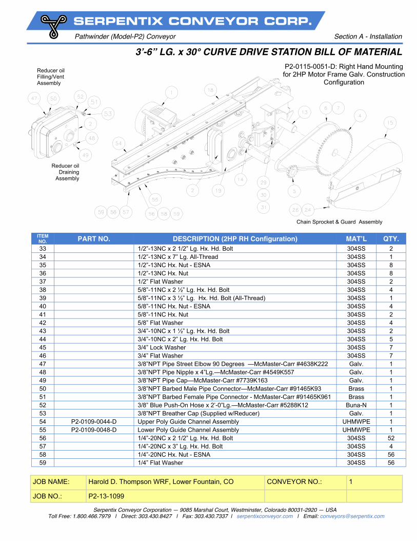
3’-6” LG. x 30° CURVE DRIVE STATION BILL OF MATERIAL Section A - Installation
JOB NAME: Harold D. Thompson WRF, Lower Fountain, CO CONVEYOR NO.: 1
JOB NO.: P2-13-1099
P2-0115-0051-D: Right Hand Mounting for 2HP Motor Frame Galv. Construction
Configuration
ITEM NO. PART NO. DESCRIPTION (2HP RH Configuration) MAT’L QTY. 33 1/2”-13NC x 2 1/2” Lg. Hx. Hd. Bolt 304SS 2 34 1/2”-13NC x 7” Lg. All-Thread 304SS 1 35 1/2”-13NC Hx. Nut - ESNA 304SS 8 36 1/2”-13NC Hx. Nut 304SS 8 37 1/2” Flat Washer 304SS 2 38 5/8”-11NC x 2 ½” Lg. Hx. Hd. Bolt 304SS 4 39 5/8”-11NC x 3 ½” Lg. Hx. Hd. Bolt (All-Thread) 304SS 1 40 5/8”-11NC Hx. Nut - ESNA 304SS 4 41 5/8”-11NC Hx. Nut 304SS 2 42 5/8” Flat Washer 304SS 4 43 3/4”-10NC x 1 ½” Lg. Hx. Hd. Bolt 304SS 2 44 3/4”-10NC x 2” Lg. Hx. Hd. Bolt 304SS 5 45 3/4” Lock Washer 304SS 7 46 3/4” Flat Washer 304SS 7 47 3/8”NPT Pipe Street Elbow 90 Degrees —McMaster-Carr #4638K222 Galv. 1 48 3/8”NPT Pipe Nipple x 4”Lg.—McMaster-Carr #4549K557 Galv. 1 49 3/8”NPT Pipe Cap—McMaster-Carr #7739K163 Galv. 1 50 3/8”NPT Barbed Male Pipe Connector—McMaster-Carr #91465K93 Brass 1 51 3/8”NPT Barbed Female Pipe Connector - McMaster-Carr #91465K961 Brass 1 52 3/8” Blue Push-On Hose x 2’-0”Lg.—McMaster-Carr #5288K12 Buna-N 1 53 3/8”NPT Breather Cap (Supplied w/Reducer) Galv. 1 54 P2-0109-0044-D Upper Poly Guide Channel Assembly UHMWPE 1 55 P2-0109-0048-D Lower Poly Guide Channel Assembly UHMWPE 1 56 1/4”-20NC x 2 1/2” Lg. Hx. Hd. Bolt 304SS 52 57 1/4”-20NC x 3” Lg. Hx. Hd. Bolt 304SS 4 58 1/4”-20NC Hx. Nut - ESNA 304SS 56 59 1/4” Flat Washer 304SS 56
Reducer oil Draining
Assembly
Reducer oil Filling/Vent Assembly
Chain Sprocket & Guard Assembly

Serpentix Conveyor Corporation — 9085 Marshal Court, Westminster, Colorado 80031-2920 — USA Toll Free: 1.800.466.7979 | Direct: 303.430.8427 | Fax: 303.430.7337 | serpentixconveyor.com | Email: [email protected]
SERPENTIX CONVEYOR CORP.Pathwinder (Model-P2) Conveyor
26” STANDARD SCRAPER MECHANISM Section A - Installation
Dwg. No.: PW-0137-0036
JOB NAME: CONVEYOR NO.:
JOB NO.:
Harold D. Thompson WRF, Lower Fountain, CO
P2-13-1099
1
ITEM NO. PARTS NO. DESCRIPTION MATERIAL NO.
REQ’D.
1 PW-0137-0065-A RevE 26” Single Scraper Mounting Bracket Galv. 1PR
2 PW-0137-0031-A RevC 20”/26”/32” Lovejoy Adjusting Plate Galv. 2
3 PW-0137-0032-A 20”/26”/32” Lovejoy Elastometric Tensioner Manuf. Prime/Paint 2
4 5/16”-18NC x 1”LG.HX.HD.Bolt 304SS 2
5 5/16”-18NC HX. Nut-ESNA 304SS 2
6 3/8”-16NC x 1” LG. HX. HD. Bolt 304SS 2
7 3/8”-16NC x 1 1/4” LG. HX. HD. Bolt 304SS 6
8 3/8”-16NC HX. Nut-ESNA 304SS 2
10 3/8”-Flat Washer 304SS 2
12 PW-0137-0023-A RevA Scraper Mount Bar 304SS 1
13 PW-0137-0103-A Backing Plate (1/8” Thick) UHMWPE 1
14 PW-0137-0095-A Blade (1/4” Thick) Neoprene 1
15 PW-0137-0023-A RevA Clamp Plate Galv. 1
16 1/4”-20NC x 1 1/4” LG. HX. HD. Bolt 304SS 12
17 1/4”-20NC HX. Nut-ESNA 304SS 12
9 3/8”-16NC HX. Nut-Shipping Zinc 4
11 3/8”-Lock Washer 304SS 4
Please Note: The items above are also located on the general arrangement
drawing in the bill of material as an as-sembly item.
RH Side Exploded view of
scraper tensioning mechanism.
LH Side
Scraper Assembly
Drive Station Structure
Structure Weld Nuts
9085 MARSHALL CT. WESTMINSTER, COLORADO 80031-2920 — USA PHONE 303-430-8427 — FAX 303-430-7337 — www.serpentix.com — [email protected]
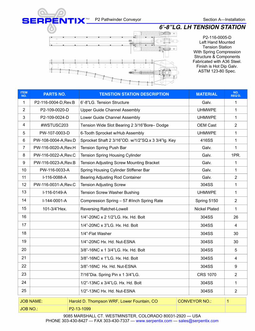
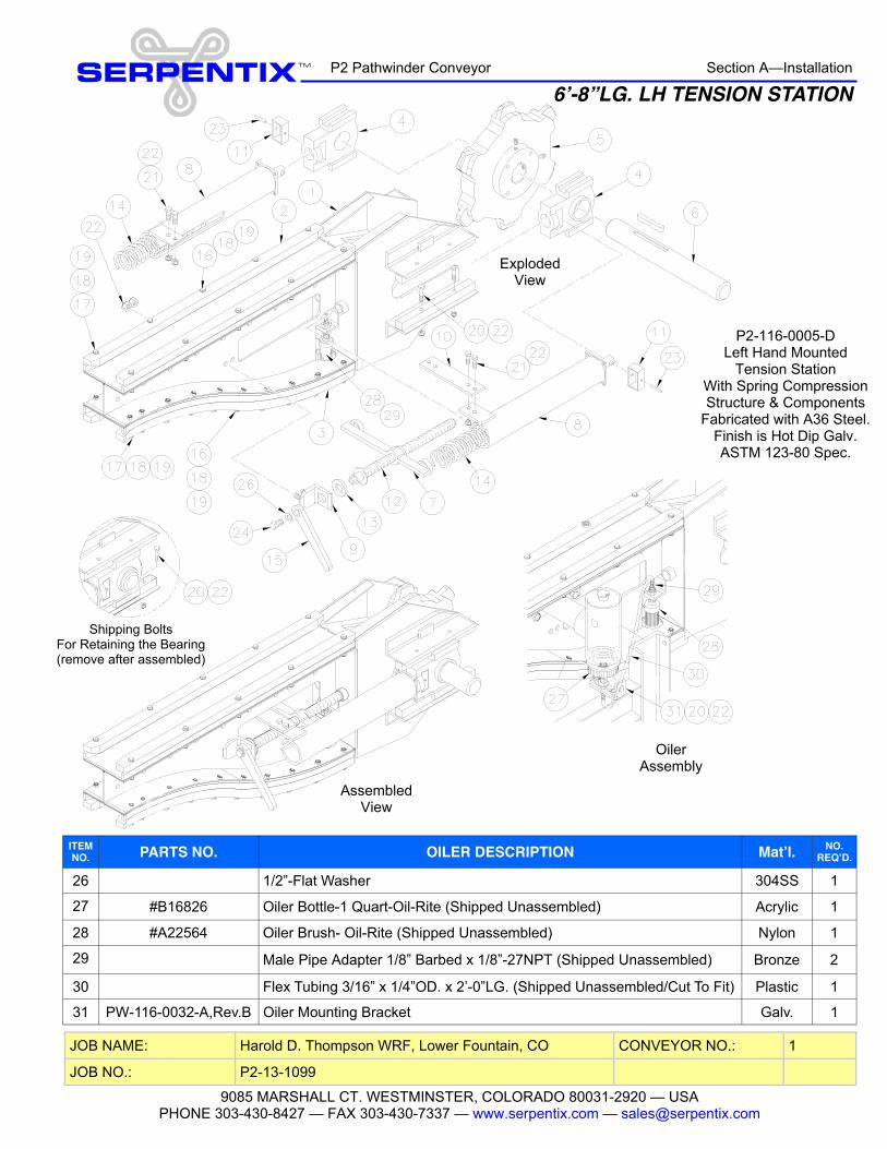
ITEM NO. PARTS NO. TENSTION STATION DESCRIPTION MATERIAL NO.
REQ’D.
1 P2-116-0004-D,Rev.B 6’-8”LG. Tension Structure Galv. 1
2 P2-109-0020-D Upper Guide Channel Assembly UHMWPE 1
3 P2-109-0024-D Lower Guide Channel Assembly UHMWPE 1
4 #WSTUSC203 Tension Wide Slot Bearing 2 3/16”Bore– Dodge OEM Cast 2
5 PW-107-0003-D 6-Tooth Sprocket w/Hub Assembly UHMWPE 1
6 PW-108-0004-A,Rev.D Sprocket Shaft 2 3/16”OD. w/1/2”SQ.x 3 3/4”lg. Key 416SS 1
7 PW-116-0020-A,Rev.H Tension Spring Push Bar Galv. 1
8 PW-116-0022-A,Rev.C Tension Spring Housing Cylinder Galv. 1PR.
9 PW-116-0023-A,Rev.B Tension Adjusting Screw Mounting Bracket Galv. 1
10 PW-116-0033-A Spring Housing Cylinder Stiffener Bar Galv. 1
11 I-116-0088-A Bearing Adjusting Rod Container Galv. 2
12 PW-116-0031-A,Rev.C Tension Adjusting Screw 304SS 1
13 I-116-0149-A Tension Screw Washer Bushing UHMWPE 1
14 I-144-0001-A Compression Spring – 57 #/inch Spring Rate Spring 5150 2
15 101-3/4”Hex. Reversing Ratchet-Lowell Nickel Plated 1
16 1/4”-20NC x 2 1/2”LG. Hx. Hd. Bolt 304SS 26
17 1/4”-20NC x 3”LG. Hx. Hd. Bolt 304SS 4
18 1/4”-Flat Washer 304SS 30
19 1/4”-20NC Hx. Hd. Nut-ESNA 304SS 30
20 3/8”-16NC x 1 3/4”LG. Hx. Hd. Bolt 304SS 5
21 3/8”-16NC x 1”LG. Hx. Hd. Bolt 304SS 4
22 3/8”-16NC Hx. Hd. Nut-ESNA 304SS 9
23 7/16”Dia. Spring Pin x 1 3/4”LG. CRS 1070 2
24 1/2”-13NC x 3/4”LG. Hx. Hd. Bolt 304SS 1
25 1/2”-13NC Hx. Hd. Nut-ESNA 304SS 2
JOB NAME: CONVEYOR NO.:
JOB NO.:
Harold D. Thompson WRF, Lower Fountain, CO
P2-13-1099
1
Section A—Installation SERPENTIX TM
6’-8”LG. LH TENSION STATION P2 Pathwinder Conveyor
P2-116-0005-D Left Hand Mounted
Tension Station With Spring Compression Structure & Components
Fabricated with A36 Steel. Finish is Hot Dip Galv. ASTM 123-80 Spec.
9085 MARSHALL CT. WESTMINSTER, COLORADO 80031-2920 — USA PHONE 303-430-8427 — FAX 303-430-7337 — www.serpentix.com — [email protected]
ITEM NO. PARTS NO. OILER DESCRIPTION Mat’l. NO.
REQ’D.
26 1/2”-Flat Washer 304SS 1
27 #B16826 Oiler Bottle-1 Quart-Oil-Rite (Shipped Unassembled) Acrylic 1
28 #A22564 Oiler Brush- Oil-Rite (Shipped Unassembled) Nylon 1
29 Male Pipe Adapter 1/8” Barbed x 1/8”-27NPT (Shipped Unassembled) Bronze 2
30 Flex Tubing 3/16” x 1/4”OD. x 2’-0”LG. (Shipped Unassembled/Cut To Fit) Plastic 1
31 PW-116-0032-A,Rev.B Oiler Mounting Bracket Galv. 1
JOB NAME: CONVEYOR NO.:
JOB NO.:
Harold D. Thompson WRF, Lower Fountain, CO
P2-13-1099
1
Section A—Installation SERPENTIX TM
6’-8”LG. LH TENSION STATION P2 Pathwinder Conveyor
Exploded View
Oiler Assembly
Shipping Bolts For Retaining the Bearing (remove after assembled)
Assembled View
P2-116-0005-D Left Hand Mounted
Tension Station With Spring Compression Structure & Components
Fabricated with A36 Steel. Finish is Hot Dip Galv. ASTM 123-80 Spec.

9085 MARSHALL CT. WESTMINSTER, COLORADO 80031-2920 — USA PHONE 303-430-8427 — FAX 303-430-7337 — www.serpentix.com — [email protected]
ITEM NO. PARTS NO. ZEROSPEED SWITCH DESCRIPTION Mat’l. NO.
REQ’D.
32 PW-116-0057-A,Rev.D RH- Zero Speed Switch Housing Bracket– Electro Sensor 304SS 1
33 PW-116-0057-A,Rev.D RH- Zero Speed Switch Sliding Bracket– Electro Sensor 304SS 1
34 1/4”-20NC x 1”LG. Hx. Hd. Bolt 304SS 4
35 1/4”-20NC Hx. Hd. Nut-ESNA 304SS 4
36 5/16”-18NC x 3/4”LG. Hx. Hd. Tap Bolt 304SS 2
37 5/16”-18NC Hx. Hd. Nut-ESNA 304SS 2
38 5/16”-Flat Washer 304SS 2
JOB NAME: CONVEYOR NO.:
JOB NO.:
Harold D. Thompson WRF, Lower Fountain, CO
P2-13-1099
1
Section A—Installation SERPENTIX TM
6’-8”LG. LH TENSION STATION P2 Pathwinder Conveyor
Zero Speed Switch Sensing Head Clearance
To the Pulsar Wrap
Exploded View of Zero Speed Switch
Mounting
Zero Speed Switch Assembled
See the GA Drawing for the Call-out Item for the Zero
Speed Switch (Shipped Separately)
Zero Speed Switch Mounting Brackets
Assembly
P2-116-0005-D Left Hand Mounted
Tension Station With Spring Compression Structure & Components
Fabricated with A36 Steel. Finish is Hot Dip Galv. ASTM 123-80 Spec.
1/8”-1/4”
Recommended Gap Distance

9085 MARSHALL CT. WESTMINSTER, COLORADO 80031-2920 — USA PHONE 303-430-8427 — FAX 303-430-7337 — www.serpentix.com — [email protected]
ITEM NO. PARTS NO. DESCRIPTION (Packed Separately) MATERIAL NO.
REQ’D.
S1 H-0104-0010-B Intermediate Attachment Nylon 5
S2 PW-0104-0007-A Guide Block– Grey Injected (Wide) Urethane 10
S4 H-0101-0122-B Belt Pans 26” MPR 5
S5 PW-0137-0095-A Scraper Blade 26” (1/4” Thk. 65 Duro) Neoprene 2
S3 PW-0106-0004-A Chain Splice Master Link Full Assembly Case Hardened 1
Section B - Maintenance SERPENTIX TM
26”-STANDARD SPARE PARTS P2 Pathwinder Conveyor
JOB NAME: CONVEYOR NO.:
JOB NO.:
Harold D. Thompson WRF, Lower Fountain, CO
P2-13-1099
1

General ArrangementDrawings


Control Panel
FU1 / 2T1
TD2TD1
8
4
6
2
5
1
7
3
14
12
13
911 10
CR18
4
6
2
5
1
7
3
14
12
13
911 10
CR28
4
6
2
5
1
7
3
14
12
13
911 10
CR38
4
6
2
5
1
7
3
14
12
13
911 10
CR4
T2N CIRCUIT BREAKER
MCB
M1/OL1
B
2
A C D E F G H I J K L
BA C D E F G H I J K L
SHEET OF
DWG
PALMER DRIVES
ENGLEWOOD, CO 80110720-484-8547
2498 SOUTH TEJON
VERIFY SCALE
BAR IS ONE INCH ONORIGINAL DRAWING0 1"
NO. DATE REVISION BY APVD
CUSTOMER
CUST PO#
CONTRACT #
DATE
DRWN
ENGR
APRVD
W.O.
S.O.
REV
SCALE
M
M
1
3
4
5
6
7
8
CONTROLS & SYSTEMS, INC.
LAYOUT
CONVEYOR SYSTEMCONTROL PANEL
L011 2
02/16/13
ARJ
ARJ
ARJ
W----
S-------
A
NTS
HAROLD THOMPSON WRFFOUNTAIN, COLORADO
SERPENTIX CONVEYOR
TBDA 02/19/13 DRAWING SUBMITTAL ARJ ARJ
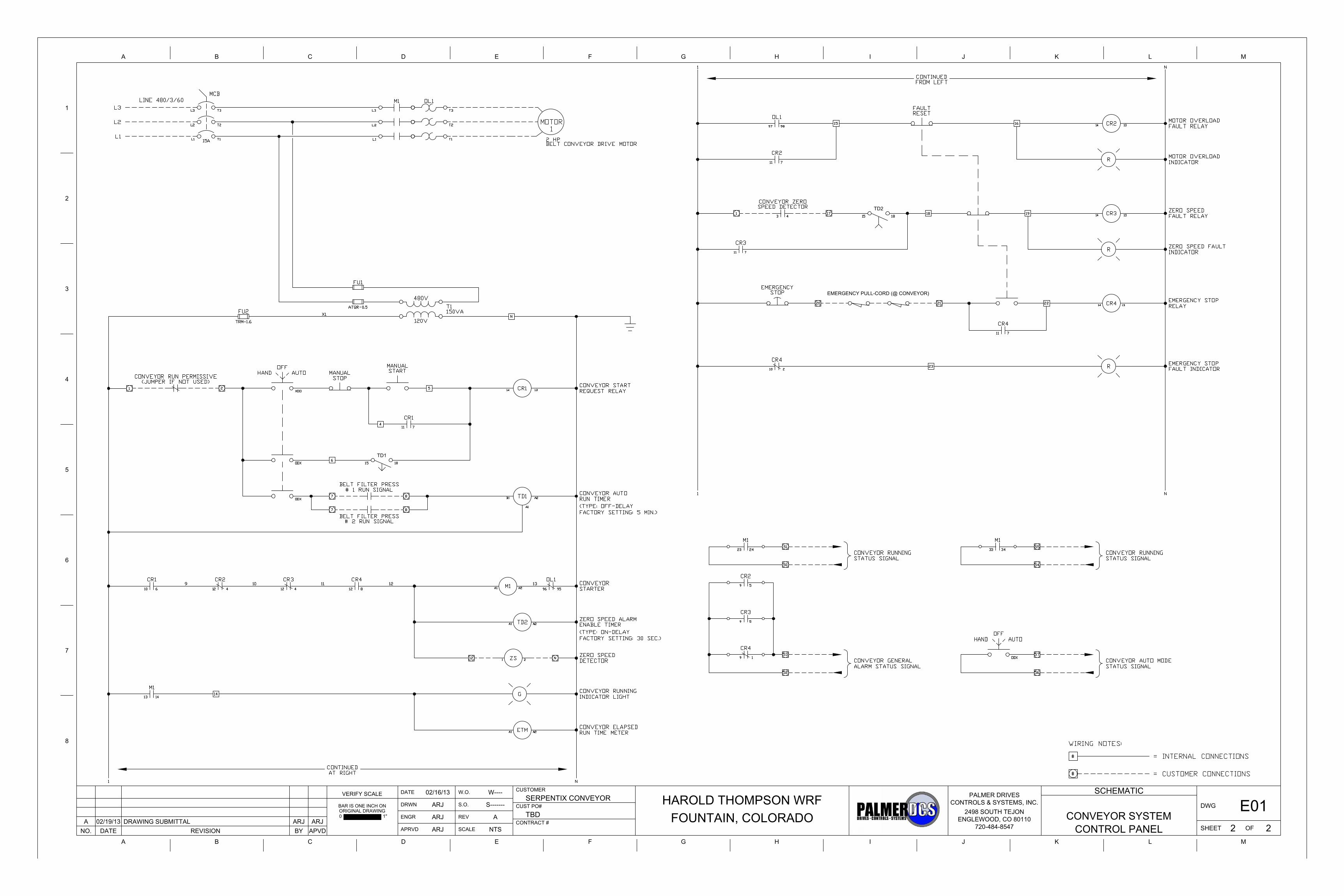
EMERGENCY PULL-CORD (@ CONVEYOR)
TD1
TD2
B
2
A C D E F G H I J K L
BA C D E F G H I J K L
SHEET OF
DWG
PALMER DRIVES
ENGLEWOOD, CO 80110720-484-8547
2498 SOUTH TEJON
VERIFY SCALE
BAR IS ONE INCH ONORIGINAL DRAWING0 1"
NO. DATE REVISION BY APVD
CUSTOMER
CUST PO#
CONTRACT #
DATE
DRWN
ENGR
APRVD
W.O.
S.O.
REV
SCALE
M
M
1
3
4
5
6
7
8
CONTROLS & SYSTEMS, INC.
SCHEMATIC
CONVEYOR SYSTEMCONTROL PANEL
E012 2
02/16/13
ARJ
ARJ
ARJ
W----
S-------
A
NTS
HAROLD THOMPSON WRFFOUNTAIN, COLORADO
SERPENTIX CONVEYOR
TBDA 02/19/13 DRAWING SUBMITTAL ARJ ARJ

Item Qty Manufacturer
11 Saginaw1 Saginaw
21 ABB Controls1 ABB Controls1 ABB Controls1 ABB Controls2 ABB Controls
31 Square D1 Square D1 Square D
41 Micron
52 Ferraz-Shawmut1 Ferraz-Shawmut
64 Idec4 Idec1 Sprecher-Schuh1 Sprecher-Schuh
71 Square D3 Square D1 Square D1 Square D1 Square D1 Square D1 Square D2 Square D
835 Phoenix Contact1 Phoenix Contact2 Phoenix Contact
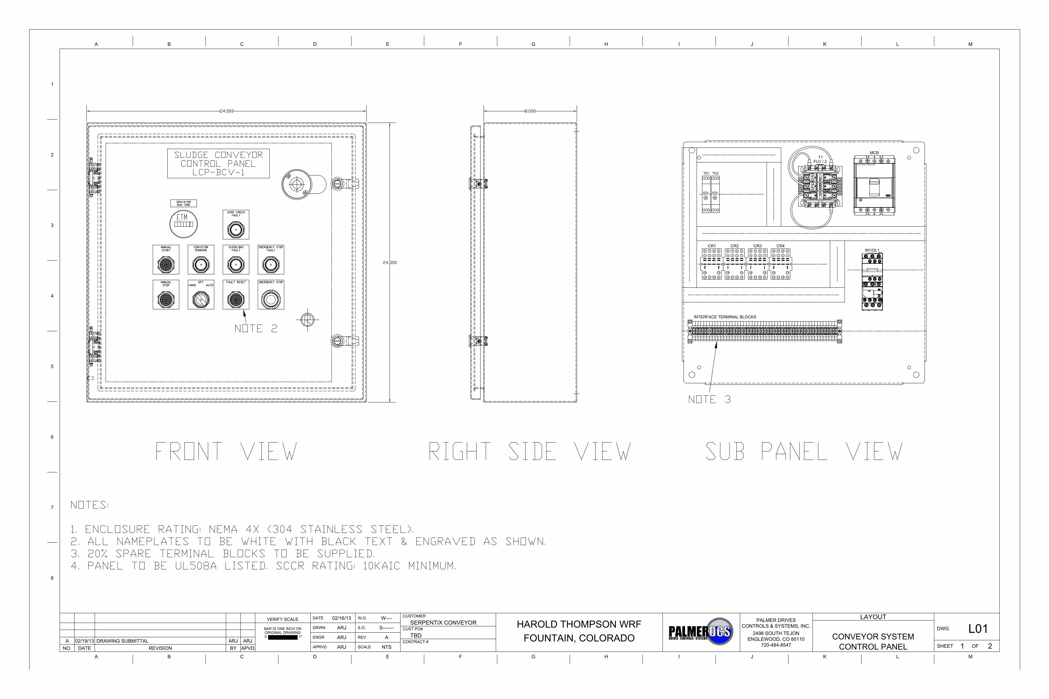
Conveyor Control Panel - Component Submittal
Palmer DCS, Inc.
Enclosures / Accessories
Tel: 720-484-8547
To: Serpentix Conveyor Company
9085 Marshall Court2498 South Tejon Street
Project: Harold Thompson WRF - Fountain, Colorado
Westminster, CO 80030
Quantities / Items for Submittal OnlyDescription Part Number Attached Document
Englewood, CO 80110Attn: Rob Nusz
SCE-24EL2408SSLPSCE-24P24
EnclosureSub Panel
Catalog Page & DrawingCatalog Page & Drawing
Circuit Breaker
Control Transformers
Fuses
Operating Mechanism
Transformer
DN20 Catalog Page
Catalog Page
T2S015TW Catalog PageCircuit Breakers / Accessories
Catalog Page
Motor Starters
Catalog Page
Class CC Fuse ATQR-0.5
B150BTZ13RBF Catalog Page
Operating Handle OHB80L6 Catalog Page
KT3VD-M Catalog Page
Overload Relay
Catalog Page
Lug Kit KT2100-3
Operating Shaft KT3VD-S
LRD08Contactor LC1D09G7 Catalog Page
Auxiliary Contact Block
Relay RH4B-UL-AC120 Catalog PageSocket SH4B-05 Catalog Page
Midget Fuse TRM-1.6 Catalog Page
Control Relays
Time Delay Relay
Indicator Light 9001SKP1G31 Catalog Page
Auxiliary Contact Block 9001-KA1 Catalog Page
Indicator Light 9001SKP1R31 Catalog Page
Pilot Devices
Time Delay Relay RZ7-FEB3TU23 Catalog PageRZ7-FEA3TU23 Catalog Page
Pushbutton 9001SKR9RH13 Catalog Page
End Clamp 0800886
Pushbutton 9001SKR1GH13 Catalog Page
End Barrier 3047028 Catalog Page
Catalog PagePushbutton 9001SKR1BH13 Catalog Page
Pushbutton 9001SKR1RH13 Catalog Page
Catalog Page
Terminal Blocks / AccessoriesTerminal Block 3044102 Catalog Page
Selector Switch 9001SKS43BH13

SECTION 1
ENCLOSURES / ACCESSORIES

Phone (989) 799-6871Fax (989) 799-4524
177 SAGINAW CONTROL & ENGINEERING • STOCK PRICE LIST
Type
4X
S.S.
Enc
losu
res
Type 4X S.S. Enclosures Saginaw Control & Engineering’s Type 4X Stainless Steel Enclosures are designed to work in a wide range of environments indoors or outdoors, and house electronic controls, instruments, and components.
These enclosures provide protection from corrosion, wind blown dust, rain, spraying water, hose directed water and ice formation on the enclosure.
Product Attributes • 304 & 316 stainless steel with #4 brushed finish. • Exclusive SCE concealed hinges on Enviroline® Series
Enclosures. • Memory retaining oil resistant urethane gasket. • Many of the standard SCE quarter turn replacement latches
and handles can be used on Enviroline® Series Enclosures.
Product Overview • Stainless Steel Pushbutton Enclosures • Stainless Steel Extra Large Pushbutton Enclosures • Stainless Steel Continuous Hinge Enclosures • Stainless Steel Single-Door Enclosures • Stainless Steel Enviroline® Series Enclosures • Two-Door Stainless Steel Enclosures • Stainless Steel Enviroline® Series Two-Door Enclosures • Stainless Steel Enviroline® Series Free-Standing Enclosures • Stainless Steel Enviroline® Junction Enclosures • Stainless Steel Enviroline® Junction Enclosures with window • Stainless Steel Enviroline® Sloping Top Enclosures

TYPE 4X 304 STAINLESS STEEL ENVIROLINE® SERIES ENCLOSURES193 SAGINAW CONTROL & ENGINEERING • STOCK PRICE LIST
TYPE 4X304 Stainless SteelEnviroline® Series
Enclosures
ENCLOSURES SUB-PANELCatalog Height Width Depth Product List Catalog Panel Panel Product List No. (A) (B) (C) Code Price No. Height (D) Width (E) Code Price
SCE-12EL1206SSLP 12.00 12.00 6.00 S5 536.16 SCE-12DLP12 9.00 9.00 P3 13.67SCE-12EL2406SSLP 12.00 24.00 6.00 S5 712.62 SCE-12P24 9.00 21.00 P3 27.86SCE-16EL1206SSLP 16.00 12.00 6.00 S5 590.45 SCE-16P12 13.00 9.00 P3 14.81SCE-16EL1208SSLP 16.00 12.00 8.00 S5 631.18 SCE-16P12 13.00 9.00 P3 14.81SCE-16EL1606SSLP 16.00 16.00 6.00 S5 654.26 SCE-16P16 13.00 13.00 P3 24.57SCE-16EL1608SSLP 16.00 16.00 8.00 S5 688.19 SCE-16P16 13.00 13.00 P3 24.57SCE-16EL2008SSLP 16.00 20.00 8.00 S5 770.98 SCE-20P16 17.00 13.00 P3 30.37SCE-20EL1606SSLP 20.00 16.00 6.00 S5 726.19 SCE-20P16 17.00 13.00 P3 30.37SCE-20EL1608SSLP 20.00 16.00 8.00 S5 770.98 SCE-20P16 17.00 13.00 P3 30.37SCE-20EL1610SSLP 20.00 16.00 10.00 S5 822.57 SCE-20P16 17.00 13.00 P3 30.37SCE-20EL2006SSLP 20.00 20.00 6.00 S5 794.06 SCE-20P20 17.00 17.00 P3 35.44SCE-20EL2008SSLP 20.00 20.00 8.00 S5 853.79 SCE-20P20 17.00 17.00 P3 35.44SCE-20EL2010SSLP 20.00 20.00 10.00 S5 909.44 SCE-20P20 17.00 17.00 P3 35.44SCE-20EL2408SSLP 20.00 24.00 8.00 S5 933.87 SCE-24P20 21.00 17.00 P3 45.57SCE-24EL1608SSLP 24.00 16.00 8.00 S5 840.20 SCE-24P16 21.00 13.00 P3 32.92SCE-24EL2006SSLP 24.00 20.00 6.00 S5 890.43 SCE-24P20 21.00 17.00 P3 45.57SCE-24EL2008SSLP 24.00 20.00 8.00 S5 933.87 SCE-24P20 21.00 17.00 P3 45.57SCE-24EL2010SSLP 24.00 20.00 10.00 S5 997.67 SCE-24P20 21.00 17.00 P3 45.57SCE-24EL2012SSLP 24.00 20.00 12.00 S5 1,058.74 SCE-24P20 21.00 17.00 P3 45.57SCE-24EL2408SSLP 24.00 24.00 8.00 S5 1,026.17 SCE-24P24 21.00 21.00 P3 53.18SCE-24EL2410SSLP 24.00 24.00 10.00 S5 1,096.74 SCE-24P24 21.00 21.00 P3 53.18SCE-24EL2412SSLP 24.00 24.00 12.00 S5 1,167.34 SCE-24P24 21.00 21.00 P3 53.18SCE-24EL2416SSLP 24.00 24.00 16.00 S5 1,323.43 SCE-24P24 21.00 21.00 P3 53.18SCE-24EL3008SSLP 24.00 30.00 8.00 S5 1,165.97 SCE-30P24 27.00 21.00 P3 63.29SCE-24EL3010SSLP 24.00 30.00 10.00 S5 1,254.20 SCE-30P24 27.00 21.00 P3 63.29SCE-30EL1606SSLP 30.00 16.00 6.00 S5 977.30 SCE-30P16 27.00 13.00 P3 45.57SCE-30EL2008SSLP 30.00 20.00 8.00 S5 1,058.74 SCE-30P20 27.00 17.00 P3 55.70SCE-30EL2010SSLP 30.00 20.00 10.00 S5 1,146.97 SCE-30P20 27.00 17.00 P3 55.70SCE-30EL2408SSLP 30.00 24.00 8.00 S5 1,167.34 SCE-30P24 27.00 21.00 P3 63.29SCE-30EL2410SSLP 30.00 24.00 10.00 S5 1,255.56 SCE-30P24 27.00 21.00 P3 63.29SCE-30EL2412SSLP 30.00 24.00 12.00 S5 1,330.21 SCE-30P24 27.00 21.00 P3 63.29SCE-30EL2416SSLP 30.00 24.00 16.00 S5 1,465.95 SCE-30P24 27.00 21.00 P3 63.29SCE-30EL3008SSLP 30.00 30.00 8.00 S5 1,337.00 SCE-30P30 27.00 27.00 P3 83.55SCE-30EL3010SSLP 30.00 30.00 10.00 S5 1,418.45 SCE-30P30 27.00 27.00 P3 83.55SCE-30EL3012SSLP 30.00 30.00 12.00 S5 1,506.67 SCE-30P30 27.00 27.00 P3 83.55SCE-30EL3608SSLP 30.00 36.00 8.00 S5 1,495.82 SCE-36P30 33.00 27.00 P3 101.27SCE-36EL2408SSLP 36.00 24.00 8.00 S5 1,316.64 SCE-36P24 33.00 21.00 P3 75.96SCE-36EL2410SSLP 36.00 24.00 10.00 S5 1,404.88 SCE-36P24 33.00 21.00 P3 75.96SCE-36EL3008SSLP 36.00 30.00 8.00 S5 1,495.82 SCE-36P30 33.00 27.00 P3 101.27SCE-36EL3010SSLP 36.00 30.00 10.00 S5 1,607.12 SCE-36P30 33.00 27.00 P3 101.27SCE-36EL3012SSLP 36.00 30.00 12.00 S5 1,703.48 SCE-36P30 33.00 27.00 P3 101.27SCE-36EL3608SSLP 36.00 36.00 8.00 S5 1,723.86 SCE-36P36 33.00 33.00 P3 118.99SCE-36EL3612SSLP 36.00 36.00 12.00 S5 1,913.89 SCE-36P36 33.00 33.00 P3 118.99SCE-42EL2410SSLP 42.00 24.00 10.00 S5 1,628.84 SCE-42P24 39.00 21.00 P3 91.14SCE-42EL3010SSLP 42.00 30.00 10.00 S5 1,783.57 SCE-42P30 39.00 27.00 P3 116.47SCE-42EL3612SSLP 42.00 36.00 12.00 S5 2,106.63 SCE-42P36 39.00 33.00 P3 136.72SCE-42EL3616SSLP 42.00 36.00 16.00 S5 2,236.93 SCE-42P36 39.00 33.00 P3 136.72SCE-48EL3612SSLP 48.00 36.00 12.00 S5 2,334.67 SCE-48P36 45.00 33.00 P3 154.46SCE-48EL3616SSLP 48.00 36.00 16.00 S5 2,545.05 SCE-48P36 45.00 33.00 P3 154.46SCE-60EL3612SSLP 60.00 36.00 12.00 S5 2,755.44 SCE-60P36 57.00 33.00 P3 189.89SCE-60EL3616SSLP 60.00 36.00 16.00 S5 2,972.63 SCE-60P36 57.00 33.00 P3 189.89SCE-72EL3016SSLP 72.00 30.00 16.00 S5 3,189.81 SCE-72P30 69.00 27.00 P3 210.15SCE-72EL3612SSLP 72.00 36.00 12.00 S5 3,278.03 SCE-72P36 69.00 33.00 P3 225.33SCE-72EL3616SSLP 72.00 36.00 16.00 S5 3,461.27 SCE-72P36 69.00 33.00 P3 225.33
Application -Designed to house electrical and electronic controls, instruments and components in areas which may be regularly hosed down or are in very wet conditions. Provides protection from dust, dirt, oil, and water. For outdoor application a drip shield is recom-mended.
Construction -• 0.075” stainless steel Type 304.• Seams continuously welded and
ground smooth. • Flange trough collar around all sides of
door opening. • Oil-resistant gasket. • Collar studs provided for mounting
optional panels. • Stainless Steel concealed hinge.• Removable and interchangeable doors.• Black quarter turn latches. • Latches are opened or closed with a
screwdriver (optional tamper-resistant inserts are available).
• Mounting holes in back of enclosure.• Mounting hardware, sealing washer
and hole plug included. • Removable print pocket. • Ground studs on door and body.
Options -• Optional mounting feet available.• Door hardware available.• Panels can be special ordered in stain-
less steel up to 48P36 size.
Finish -#4 brushed finish on all exterior surfaces. Optional panels are powder coated white.
Industry Standards -NEMA Type 4, 4X, 12 & 13UL Listed Type 4, 4X, & 12CSA Type 4, 4X & 12IEC 60529 IP 66
Type
4X
S.S.
Enc
losu
res

SAGINAW CONTROL & ENGINEERING • STOCK PRICE LIST 194
Phone (989) 799-6871Fax (989) 799-4524
TYPE 4X STAINLESS STEEL ENVIROLINE® SERIES ENCLOSURESTECHNICAL DATA
Type 4X S.S. Enclosures

SECTION 2
CIRCUIT BREAKERS / ACCESSORIES & SURGE PROTECTION DEVICES
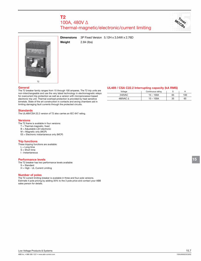
15TmaxMCCBs
Low Voltage Products & Systems 15.7
15
T2
General
Standards
Versions
Trip functions
L = Long timeS = Short time
Performance levels
S = Standard
Number of poles
UL489 / CSA C22.2 Interrupting capacity (kA RMS)
Dimensions Weight

15Tmax
MCCBs
Low Voltage Products & Systems
15
Rating
Discount schedule S2T
T2
$ 690 690
690 690 690 690 690 793 793 793 793
T2
$ 942 942
942 942 942 942 942 1153 1153 1153 1153
Rating
$ 760
872
Rating
T2
$ 1025
1268
Rating
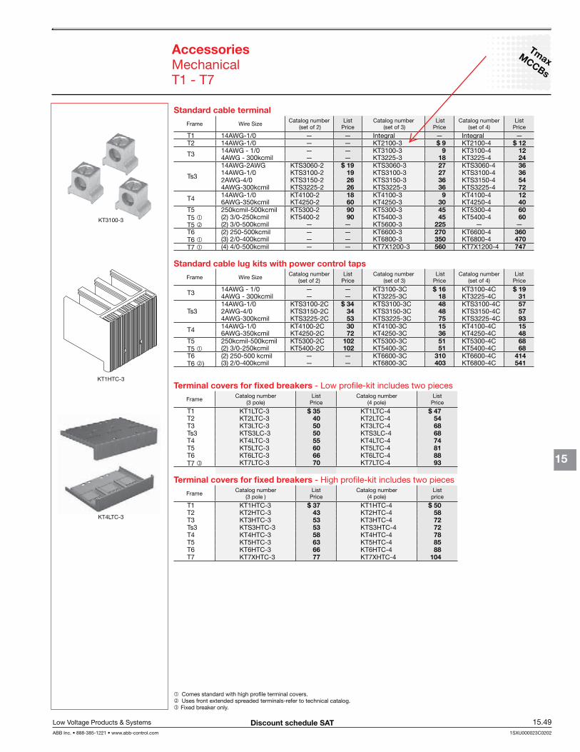
TmaxMCCBs
Low Voltage Products & Systems 15.49
15
AccessoriesMechanical
1 .2 .3 .
Discount schedule SAT
Standard cable terminalFrame Wire Size List
Price ListPrice
ListPrice
T1 Integral IntegralT2 $ 9 $ 12
T3 9 1218 24
Ts3
$ 19 27 3619 27 3626 36 5426 36 72
T4 18 9 1260 30 40
T5 90 45 60T5 1 90 45 60T5 2 225T6 270 360T6 1 350 470T7 1 560 747
Standard cable lug kits with power control tapsFrame Wire Size List
Price ListPrice
ListPrice
T3 $ 16 $ 1918 31
Ts3$ 34 48 57
34 48 5753 75 93
T4 30 15 1572 36 48
T5 102 51 68T5 1 102 51 68T6 310 414T6 2 403 541
Terminal covers for fixed breakers Frame List
PriceList
Price
T1 $ 35 $ 47T2 40 54T3 50 68Ts3 50 68T4 55 74T5 60 81T6 66 88T7 3 70 93
Terminal covers for fixed breakers Frame List
PriceList
price
T1 $ 37 $ 50T2 43 58T3 53 72Ts3 53 72T4 58 78T5 63 85T6 66 88T7 77 104

TmaxMCCBs
Low Voltage Products & Systems 15.51
15
Discount schedule SAT
Accessories
Locking devices and handle operators
Padlock locking deviceFrame Style Locking Position Breaker
Mounting List
Price
T1,T2,T3 PLL Fixed $ 35
Ts3 FLD 50 55
FLD 40 55
T6 FLD 40 55
T7 PLL Fixed, Drawout 55
Keylocks-Rotary handle mechanismFrame Style Locking Position List
Price
T1,T2,T3 RHL Different $ 94Ts3 Different 58
Different 58T6 Different 79T7 Different 79
Direct mount rotary operator handleFrame Breaker
Mounting List
Price
T1,T2,T3 $ 146Ts3 146Ts3 146T5 275T5 275T6 310T6 310T7 348T7 348
Variable depth handle operatorsFrame NEMA rating Mechanism List
Price ListPrice
Handle catalog ListPrice
1,3R,12 - - 1 1
$ 80
4, 4X $ 72 $ 28 1 1
130
1 - 35 87
Ts3
1,3R,12 - 24 1 80
4,4X 72 26 1 120
- 32 -
1 - 2428 87
1,3R,12 - 24 1 80
4,4X 65 26 1 120
- 32 -- - -
1 - 36 87
T6
1,3R,12 - 24 1 90
4,4X 90 26 1 130
- 32 -1 - 36 87
T7
1,3R,12 - 24 1 100
95 26 1 140
- 32 -1 - 100 100
1 Discount schedule

SECTION 3
MOTOR STARTERS

www.schneider-electric.us
18IE
C C
ON
TA
CT
OR
S A
ND
S
TA
RT
ER
S
18-4 © 2009 Schneider ElectricAll Rights Reserved
Contactors & Overload Relays
TeSys® D Non-reversingRefer to Catalog 8502CT9901
TeSys D contactor accessories . . . . . . . . . . . . . . . . . . . . pages 18-8 to 18-11TeSys D overload relay accessories . . . . . . . . . . . . . . . . . . . . . . . page 18-16TeSys D replacement coils. . . . . . . . . . . . . . . . . . . . . . . pages 18-17 to 18-19Dimensions. . . . . . . . . . . . . . . . . . . . . . . . . . . . . . . . . . . pages 18-40 to 18-46TeSys T. . . . . . . . . . . . . . . . . . . . . . . . . . . . . . . . . . . . . . . . . . . . . pages 16-91
LC1D09
LC1D40A
LC1D093
LC1D115
LRD22
LRD3
E164862CCN NLDX
LR43364Class 3211 04
Table 18.1: 3- or 4-Pole Screw Terminal Connections
Maximum Horsepower RatingsMaximum Current
Utilization Categories
No of PolesInstantaneous
AuxiliaryContacts Catalog
Number a$ Price
Single Phase Three Phase InductiveAC3
Amperes
ResistiveAC1
AmperesN.O. N.C. N.O. N.C.
115 V hp 230 V hp 200 V hp 230 V hp 460 V hp 575 V hp AC Coils DC Coils
0.5 1 2 2 5 7.5 920
30
1 1LC1D09 cde 94.00 119.00
— — — — — — — 4 LC1DT20 c 94.00 119.00— — — — — — — 2 2 LC1D098 c 94.00 119.001 2 3 3 7.5 10 12
253
01 1
LC1D12 cde 119.00 149.00— — — — — — — 4 LC1DT25 c 119.00 149.00— — — — — — — 2 2 LC1D128 c 119.00 149.001 3 5 5 10 15 18
323
01 1
LC1D18 cd 136.00 160.00— — — — — — — 4 LC1DT32 c 149.00 183.00— — — — — — — 2 2 LC1D188 c 149.00 183.002 3 7.5 7.5 15 20 25
403
01 1
LC1D25 cd 151.00 181.00— — — — — — — 4 LC1DT40 c 193.00 240.00— — — — — — — 2 2 LC1D258 c 193.00 240.002 5 10 10 20 30 32 50 3 0 1 1 LC1D32 cd 172.00 213.003 5 10 10 30 30 40
603
01 1 LC1D40A 218.00 275.00
— — — — — — — 4 0 0 LC1DT60A 296.00 353.003 7.5 15 15 40 40 50
803
0 1 1LC1D50A 234.00 291.00
5 10 20 20 40 50 65 3 LC1D65A 322.00 379.00— — — — — — — 4 0 0 0 LC1DT80A 446.00 503.007.5 15 25 30 60 60 80
1253
01 1 LC1D80 363.00 420.00
— — — — — — — 40 0
LC1D80004 b 489.00 524.00— — — — — — — 2 2 LC1D80008 b 489.00 524.00— — 30 40 75 100 115
2003
01 1
LC1D115 479.00 479.00— — 40 50 100 125 150 3 LC1D150 696.00 696.00— — — — — — — 4 0 0 LC1D115004 630.00 630.00
a Complete catalog number with coil voltage code from table on page 18-6; example, LC1D09G7. b For DC version of these devices replace the 'C' with 'P' (ex. LC1D80004** becomes LP1D80004**). This applies only to 80A 4 pole devices.c On LC1D09 - LC1D65A and LC1DT20 through LC1DT80A, for ring tongue versions add '6' to the catalog number prior to adding the voltage code
(ex. LC1D09G7 becomes LC1D096G7 and LC1D50AG7 becomes LC1D50A6G7). No price adder for this modification.d On LC1D09 - LC1D65A, for spring terminals versions add '3' to the catalog number prior to adding the voltage code (ex. LC1D12G7 becomes
LC1D123G7 and LC1D40AG7 becomes LC1D40A3G7 - Note that 40A to 65A spring terminals are only on the control terminations and not on power terminations). No price adder for this modification.
e On LC1D09 and LC1D12 only, for slip-on connector versions add "9" to the catalog number prior to adding the voltage code (ex. LC1D09G7 becomes LC1D099G7). No price adder for this modification.
Table 18.2: TeSys D Overload Relays — Ambient Compensated, Bi-Metallic Direct Mount
Current Setting Range Amperes
For Direct Mountingto LC1...
Class 10 with Single Phase
Sensitivity
Class 10 without Single Phase
Sensitivity
Class 20 with Single Phase
Sensitivity
Class 20 without Single Phase
Sensitivity$ Price
0.10–0.16
D09–D32
LRD01 LR3D01 — —
60.00
0.16–0.25 LRD02 LR3D02 — —0.25–0.40 LRD03 LR3D03 — —0.40–0.63 LRD04 LR3D04 — —
0.63–1 LRD05 LR3D05 — —1–1.6 LRD06 LR3D06 — —
1.6–2.5 LRD07 LR3D07 — —2.5–4 LRD08 LR3D08 LRD1508 LR3D1508A14–6 LRD10 LR3D10 LRD1510 LR3D1510A1
5.5–8 D09–D32 LRD12 LR3D12 LRD1512 LR3D1512A1
62.00
7–10 D09–D32 LRD14 LR3D14 LRD1514 LR3D1514A19–13 D12–D32 LRD16 LR3D16 LRD1516 LR3D1516A112–18 D18–D32 LRD21 LR3D21 LRD1521 LR3D1521A116–24 D25–D32 LRD22 LR3D22 — —17–25 D25–D32 — — LRD1522 LR3D1522A123–32 D25–D32 LRD32 LR3D32 — —
73.0023–28 D25–D32 — — LRD1530 LR3D1530A125–32 D25–D32 — — LRD1532 LR3D1532A130–38 D32 LRD35 LR3D35 — —9-13 D40A-D65A f LRD313 LR3D313 LRD313L —
107.00
12-18 D40A-D65A f LRD318 LR3D318 LRD318L —16-25 D40A-D65A f LRD325 LR3D325 LRD325L —23-32 D40A-D65A f LRD332 LR3D332 LRD332L —30-40 D40A-D65A f LRD340 LR3D340 LRD340L —37-50 D40A-D65A f LRD350 LR3D350 LRD350L —48-65 D40A-D65A f LRD365 LR3D365 LRD365L —17-25 D40-D80 g LRD3322 LR3D3322 LR2D3522 LR3D3522
107.0023-32 D40-D80 g LRD3353 LR3D3353 LR2D3553 LR3D355330-40 D40-D80 g LRD3355 LR3D3355 LR2D3555 LR3D355537-50 D50-D80 g LRD3357 LR3D3357 LR2D3557 LR3D355748-65 D50-D80 g LRD3359 LR3D3359 LR2D3559 LR3D355955–70 D65–D80 LRD3361 LR3D3361 LR2D3561 LR3D3561
127.0063–80 D65–D80 LRD3363 LR3D3363 LR2D3563 LR3D356380–104 D80 LRD3365 — — —80–104 D115–D150 LRD4365 — — —
362.0095–120 D115–D150 LRD4367 — — —110–140 D150 LRD4369 — — —
f Overload relays with Everlink termination - direct mount to D40A to D65A only.g Direct mount to old D2 style D40 to D65 (no Everlink terminations) and to D80 only.
I12 Discount Schedule
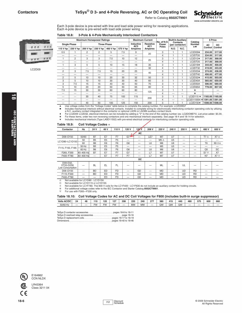
www.schneider-electric.us
18IE
C C
ON
TA
CT
OR
S A
ND
S
TA
RT
ER
S
18-6 © 2009 Schneider ElectricAll Rights Reserved
Contactors TeSys® D 3- and 4-Pole Reversing, AC or DC Operating CoilRefer to Catalog 8502CT9901
Each 3-pole device is pre-wired with line and load side power wiring for reversing applications.Each 4-pole device is pre-wired with load side power wiring
TeSys D contactor accessories . . . . . . . . . . . . . . . . . . . . pages 18-8 to 18-11TeSys D overload relay accessories . . . . . . . . . . . . . . . . . . . . . . . page 18-16TeSys D replacement coils. . . . . . . . . . . . . . . . . . . . . . . pages 18-17 to 18-19Dimensions. . . . . . . . . . . . . . . . . . . . . . . . . . . . . . . . . . . pages 18-40 to 18-46
LC2D09
E164862CCN NLDX
LR43364Class 3211 04
Table 18.8: 3-Pole & 4-Pole Mechanically Interlocked ContactorsMaximum Horsepower Ratings Maximum Current
No. of N.O. Power Poles
Built In Auxiliary Contacts
(per contactor)Catalog Numberab
$ Price
Single Phase Three Phase Inductive AC3
Amperes
Resistive AC1
AmperesAC
ControlDC
Control115 V hp 230 V hp 200 V hp 230 V hp 460 V hp 575 V hp N.O. N.C.0.5 1 2 2 5 7.5 9
203 1 1 LC2D09c 234.00 317.00
— — — — — — — 4 1 1 LC2DT20 234.00 317.001 2 3 3 7.5 10 12
253 1 1 LC2D12c 317.00 368.00
— — — — — — — 4 1 1 LC2DT25 317.00 368.001 3 5 5 10 15 18 35 3 1 1 LC2D18c 344.00 400.00— — — — — — — 32 4 1 1 LC2DT32 419.00 443.002 3 7.5 7.5 15 20 25
403 1 1 LC2D25c 374.00 436.00
— — — — — — — 4 1 1 LC2DT40 456.00 477.002 5 10 10 20 30 32 50 3 1 1 LC2D32c 415.00 503.003 5 10 10 30 30 40 60 3 1 1 LC2D40A 565.00 650.003 7.5 15 15 40 40 50 70 3 1 1 LC2D50A 596.00 680.005 10 20 20 50 50 65 80 3 1 1 LC2D65A 778.00 857.00
7.5 15 30 30 60 60 80125
3 1 1 d — — — — — — — — 4 — — d — — — 30 40 75 100 115
2003 1 1 LC2D115 e 1165.00 1165.00
— — — — — — — 4 — — LC2D115004 e 1391.00 1391.00— — 40 50 100 125 150 200 3 1 1 LC2D150e 1598.00 1598.00
a Use voltage codes from the “Voltage Codes” table below to complete the catalog number. For example: LC2D09G7b Includes mechanical interlock without electrical contacts. Installer to complete wiring for electronically interlocking contactor operating coils by utilizing
a N.C. auxiliary contact integrated in the contactor or optional LADN or LAD8N auxiliary contact block.c For LC2D09–LC2D32, electrical interlock can be included by adding a ”V” to the end of the catalog number (ex: LC2DO9B7V). List price adder: $5.00.d For these items, order two non-reversing contactors and one mechanical interlock separately. See page 18-4 and 18-14 for selection.e Includes mechanical interlock (Type LA9D11502) with pre-wired electrical contacts for interlocking contactor operating coils.
Table 18.9: Coil Voltage Codes iContactor Hz 24 V 48 V 110 V 120 V 125 V 208 V 220 V 240 V 250 V 440 V 480 V 600 V
ACD09–D150 50/60 B7 E7 F7 G7 — LE7 M7 U7 — — T7 f X7 f
LC1D80–LC1D15050 B5 E5 F5 — — — M5 f U5 — — — —60 B6 E6 F6 G6 — L6 M6 U6 — — T6 X6 gf
F115, F150, F18550 Hz B5 E5 F5 — — — M5 U5 — — — —60 Hz B6 E6 F6 G6 — L6 M6 U6 — — Q5 SC
F265, F330 40–400 Hz B7 E7 F7 G7 — L7 M7 U7 — — S7 j X7F400–F780 40–400 Hz — E7 F7 F7 — L7 M7 U7 — — N7 X7 h
DCD09-D32,
DT20-D258Low Consumption
— BL EL FL — — — ML — UL — — —
D09–D150 — BD ED FD — GD — MD — UD RD — —F115–F330 — BD ED FD — GD — MD — UD RD — —F400–F780 — — ED FD — GD — MD — UD RD — —
f Not available for LC1D80 - LC1D150.g Not available for LC1D115 or LC1D150.h Not available for LC1F780. The 600 V coils for the LC1F400 - LC1F630 do not include an auxiliary contact for holding circuits.i For additional voltage codes refer to the IEC Contactor and Starter Catalog 8502CT9901. j For use with F265—F330 only.
Table 18.10: Coil Voltage Codes for AC and DC Coil Voltages for F800 (includes built-in surge suppressor)Volts AC/DC 24 48 110 120 127 208 220 240 277 380 415 440 480 575 600 660
50/60 Hz — — FW FW FW — MW MW — QW QW QW — — — —
I12 Discount Schedule

SECTION 4
CONTROL TRANSFORMERS
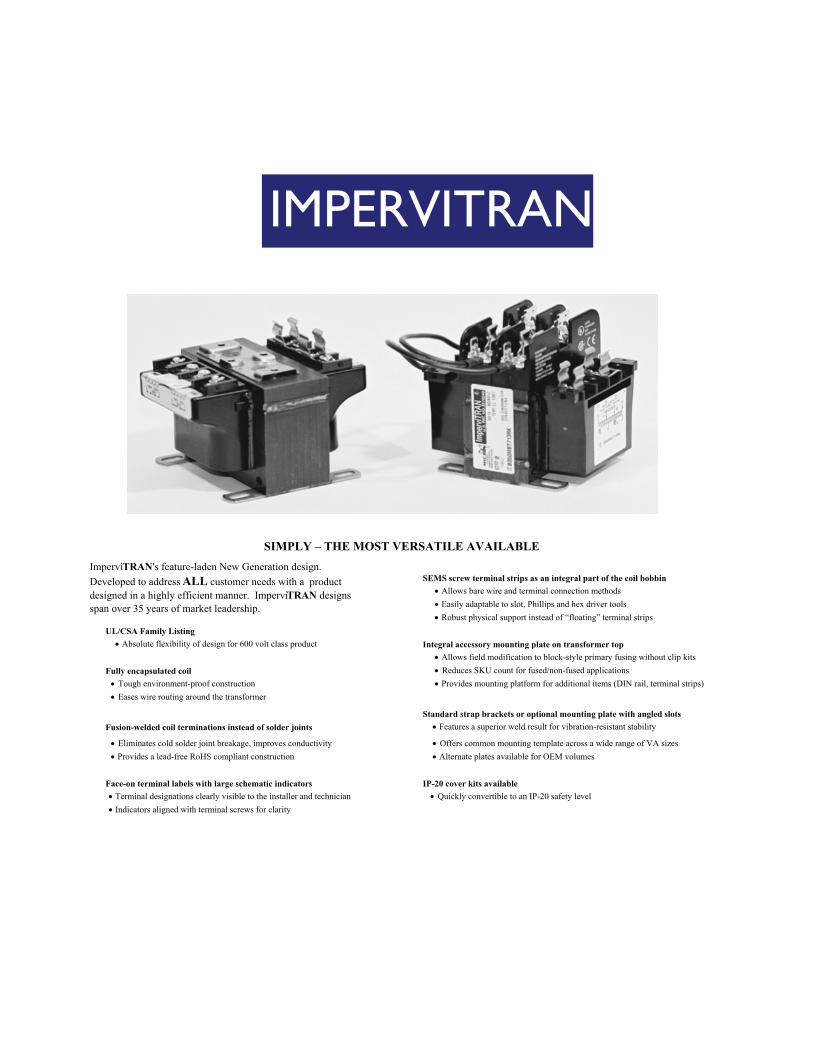
IMPERVITRAN
SIMPLY – THE MOST VERSATILE AVAILABLE
SEMS screw terminal strips as an integral part of the coil bobbin!!!!!!!!!!!!!!!!!!!!!!!!!!!!!!!!!!!" Allows bare wire and terminal connection methods!!!!!!!!!!!!!!!!!!!!!!!!!!!!!!!!!!!" Easily adaptable to slot, Phillips and hex driver tools!!!!!!!!!!!!!!!!!!!!!!!!!!!!!!!!!!!" Robust physical support instead of “floating” terminal strips
UL/CSA Family Listing!!!!!!!!!!!!!!!!!!!!!!!!!!!!!!!!!!" Absolute flexibility of design for 600 volt class product Integral accessory mounting plate on transformer top
!!!!!!!!!!!!!!!!!!!!!!!!!!!!!!!!!!!" Allows field modification to block-style primary fusing without clip kitsFully encapsulated coil !!!!!!!!!!!!!!!!!!!!!!!!!!!!!!!!!!!"!Reduces SKU count for fused/non-fused applications
!!!!!!!!!!!!!!!!!!!!!!!!!!!!!!!!"!Tough environment-proof construction !!!!!!!!!!!!!!!!!!!!!!!!!!!!!!!!!!!" Provides mounting platform for additional items (DIN rail, terminal strips)!!!!!!!!!!!!!!!!!!!!!!!!!!!!!!!!"!Eases wire routing around the transformer
Standard strap brackets or optional mounting plate with angled slotsFusion-welded coil terminations instead of solder joints !!!!!!!!!!!!!!!!!!!!!!!!!!!!!!!!!!" Features a superior weld result for vibration-resistant stability
!!!!!!!!!!!!!!!!!!!!!!!!!!!!!!!!"!Eliminates cold solder joint breakage, improves conductivity !!!!!!!!!!!!!!!!!!!!!!!!!!!!!!!!!!"!Offers common mounting template across a wide range of VA sizes!!!!!!!!!!!!!!!!!!!!!!!!!!!!!!!!" Provides a lead-free RoHS compliant construction !!!!!!!!!!!!!!!!!!!!!!!!!!!!!!!!!!" Alternate plates available for OEM volumes
Face-on terminal labels with large schematic indicators IP-20 cover kits available!!!!!!!!!!!!!!!!!!!!!!!!!!!!!!!" Terminal designations clearly visible to the installer and technician !!!!!!!!!!!!!!!!!!!!!!!!!!!!!!!!!"!Quickly convertible to an IP-20 safety level!!!!!!!!!!!!!!!!!!!!!!!!!!!!!!!" Indicators aligned with terminal screws for clarity
ImperviTRAN's feature-laden New Generation design.Developed to address ALL customer needs with a productdesigned in a highly efficient manner. ImperviTRAN designs span over 35 years of market leadership.
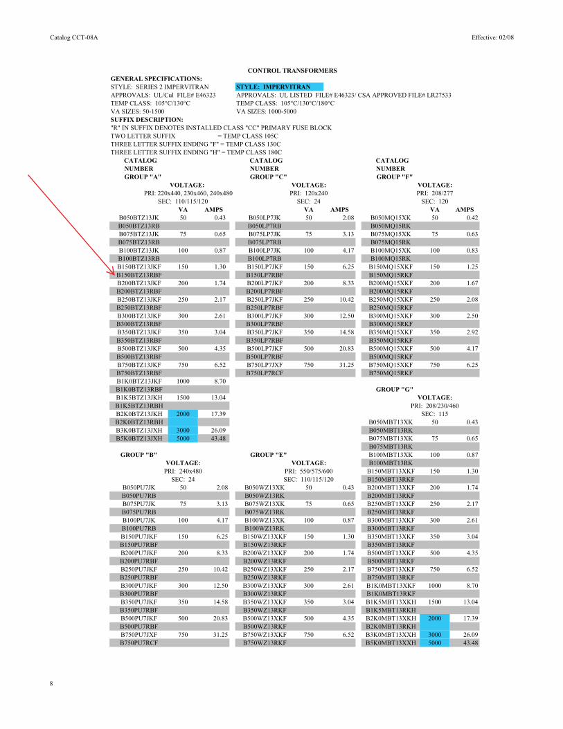
Catalog CCT-08A Effective: 02/08
CONTROL TRANSFORMERSGENERAL SPECIFICATIONS: STYLE: SERIES 2 IMPERVITRAN STYLE: IMPERVITRANAPPROVALS: UL/Cul FILE# E46323 APPROVALS: UL LISTED FILE# E46323/ CSA APPROVED FILE# LR27533TEMP CLASS: 105°C/130°C TEMP CLASS: 105°C/130°C/180°CVA SIZES: 50-1500 VA SIZES: 1000-5000SUFFIX DESCRIPTION:"R" IN SUFFIX DENOTES INSTALLED CLASS "CC" PRIMARY FUSE BLOCKTWO LETTER SUFFIX = TEMP CLASS 105CTHREE LETTER SUFFIX ENDING "F" = TEMP CLASS 130CTHREE LETTER SUFFIX ENDING "H" = TEMP CLASS 180C
CATALOG CATALOG CATALOGNUMBER NUMBER NUMBER
GROUP "A" GROUP "C" GROUP "F" VOLTAGE: VOLTAGE: VOLTAGE:
PRI: 220x440, 230x460, 240x480 PRI: 120x240 PRI: 208/277SEC: 110/115/120 SEC: 24 SEC: 120
VA AMPS VA AMPS VA AMPSB050BTZ13JK 50 0.43 B050LP7JK 50 2.08 B050MQ15XK 50 0.42B050BTZ13RB B050LP7RB B050MQ15RK B075BTZ13JK 75 0.65 B075LP7JK 75 3.13 B075MQ15XK 75 0.63B075BTZ13RB B075LP7RB B075MQ15RKB100BTZ13JK 100 0.87 B100LP7JK 100 4.17 B100MQ15XK 100 0.83B100BTZ13RB B100LP7RB B100MQ15RKB150BTZ13JKF 150 1.30 B150LP7JKF 150 6.25 B150MQ15XKF 150 1.25B150BTZ13RBF B150LP7RBF B150MQ15RKFB200BTZ13JKF 200 1.74 B200LP7JKF 200 8.33 B200MQ15XKF 200 1.67B200BTZ13RBF B200LP7RBF B200MQ15RKFB250BTZ13JKF 250 2.17 B250LP7JKF 250 10.42 B250MQ15XKF 250 2.08B250BTZ13RBF B250LP7RBF B250MQ15RKFB300BTZ13JKF 300 2.61 B300LP7JKF 300 12.50 B300MQ15XKF 300 2.50B300BTZ13RBF B300LP7RBF B300MQ15RKFB350BTZ13JKF 350 3.04 B350LP7JKF 350 14.58 B350MQ15XKF 350 2.92B350BTZ13RBF B350LP7RBF B350MQ15RKFB500BTZ13JKF 500 4.35 B500LP7JKF 500 20.83 B500MQ15XKF 500 4.17B500BTZ13RBF B500LP7RBF B500MQ15RKFB750BTZ13JKF 750 6.52 B750LP7JXF 750 31.25 B750MQ15XKF 750 6.25B750BTZ13RBF B750LP7RCF B750MQ15RKFB1K0BTZ13JKF 1000 8.70 B1K0BTZ13RBF GROUP "G"B1K5BTZ13JKH 1500 13.04 VOLTAGE:B1K5BTZ13RBH PRI: 208/230/460B2K0BTZ13JKH 2000 17.39 SEC: 115B2K0BTZ13RBH B050MBT13XK 50 0.43B3K0BTZ13JXH 3000 26.09 B050MBT13RK B5K0BTZ13JXH 5000 43.48 B075MBT13XK 75 0.65
B075MBT13RK GROUP "B" GROUP "E" B100MBT13XK 100 0.87
VOLTAGE: VOLTAGE: B100MBT13RKPRI: 240x480 PRI: 550/575/600 B150MBT13XKF 150 1.30
SEC: 24 SEC: 110/115/120 B150MBT13RKFB050PU7JK 50 2.08 B050WZ13XK 50 0.43 B200MBT13XKF 200 1.74B050PU7RB B050WZ13RK B200MBT13RKFB075PU7JK 75 3.13 B075WZ13XK 75 0.65 B250MBT13XKF 250 2.17B075PU7RB B075WZ13RK B250MBT13RKFB100PU7JK 100 4.17 B100WZ13XK 100 0.87 B300MBT13XKF 300 2.61B100PU7RB B100WZ13RK B300MBT13RKFB150PU7JKF 150 6.25 B150WZ13XKF 150 1.30 B350MBT13XKF 350 3.04B150PU7RBF B150WZ13RKF B350MBT13RKFB200PU7JKF 200 8.33 B200WZ13XKF 200 1.74 B500MBT13XKF 500 4.35B200PU7RBF B200WZ13RKF B500MBT13RKFB250PU7JKF 250 10.42 B250WZ13XKF 250 2.17 B750MBT13XKF 750 6.52B250PU7RBF B250WZ13RKF B750MBT13RKFB300PU7JKF 300 12.50 B300WZ13XKF 300 2.61 B1K0MBT13XKF 1000 8.70B300PU7RBF B300WZ13RKF B1K0MBT13RKF B350PU7JKF 350 14.58 B350WZ13XKF 350 3.04 B1K5MBT13XKH 1500 13.04B350PU7RBF B350WZ13RKF B1K5MBT13RKH B500PU7JKF 500 20.83 B500WZ13XKF 500 4.35 B2K0MBT13XKH 2000 17.39B500PU7RBF B500WZ13RKF B2K0MBT13RKHB750PU7JXF 750 31.25 B750WZ13XKF 750 6.52 B3K0MBT13XXH 3000 26.09B750PU7RCF B750WZ13RKF B5K0MBT13XXH 5000 43.48
8
SECTION 5
FUSES

A 16
AC: 1/10 to 30A 600VAC, 200kA I.R.
DC: 1/10 to 30A300VDC, 100kA I.R.
➤
➤
AMP-TRAP 2000®
ATQR
Ratings
Features/Benefits
Time delay for control transformer inrush loads without nuisance openingHighly current limiting for low peak let-thru current Rejection-style design prevents replacement errors (when used with recommended fuse blocks)High-visibility orange label ensures instant recognition, and simplifies replacementMetal-embossed date and catalog number for traceability and lasting identificationFiberglass body provides dimensional stability in harsh industrial settingsHigh-grade silica filler ensures fast arc quenching and high current limitation
➤
➤
➤
➤
➤
➤
➤
TAKE CONTROL OF FAULT CURRENTS HEADED FOR YOUR CONTROL TRANSFORMER
ATQR small-dimension fuses feature time delaycharacteristics ideally suited for the high inrushcurrents of control transformers, solenoids, and similar inductive loads. The newest member of our Amp-trap 2000® family of fuses - ATQR fuses provide superior protection for the branch circuits of electrical distribution systems.
TIME DELAY/CLASS CC
UL Listed to Standard 248-4
DC Listed to UL Standard 248
CSA Certified to Standard C22.2 No. 248.4
➤
➤
➤
ApprovalsAPPLICATIONS:
Control TransformersSolenoidsInductive LoadsLighting, Heating & General-purpose Loads
➤➤➤➤
HIGHLIGHTS:
Time DelayBest Choice for Small Transformer ProtectionMost Current-Limiting
➤➤
➤
A 16

A
A 17
A
A 17
TIME DELAY/CLASS CC FUSES ATQR
AMP-TRAP 2000®
AMPERE CATALOG AMPERE CATALOG AMPERE CATALOG AMPERE CATALOG RATING NUMBER RATING NUMBER RATING NUMBER RATING NUMBER 1/10 ATQR1/10 8/10 ATQR8/10 2-8/10 ATQR2-8/10 7-1/2 ATQR7-1/2 1/8 ATQR1/8 1 ATQR1 3 ATQR3 8 ATQR8 3/16 ATQR3/16 1-1/8 ATQR1-1/8 3-2/10 ATQR3-2/10 9 ATQR9 2/10 ATQR2/10 1-1/4 ATQR1-1/4 3-1/2 ATQR3-1/2 10 ATQR10 1/4 ATQR1/4 1-4/10 ATQR1-4/10 4 ATQR4 12 ATQR12 3/10 ATQR3/10 1-1/2 ATQR1-1/2 4-1/2 ATQR4-1/2 15 ATQR15 4/10 ATQR4/10 1-6/10 ATQR1-6/10 5 ATQR5 17-1/2 ATQR17-1/2 1/2 ATQR1/2 1-8/10 ATQR1-8/10 5-6/10 ATQR5-6/10 20 ATQR20 6/10 ATQR6/10 2 ATQR2 6 ATQR6 25 ATQR25 3/4 ATQR3/4 2-1/4 ATQR2-1/4 6-1/4 ATQR6-1/4 30 ATQR30 2-1/2 ATQR2-1/2 7 ATQR7
Standard Fuse Ampere Ratings, Catalog Numbers
Recommended Fuse Blocks for Class CC Fuses
ADDER 30310R 30320R 30350R 1 USCC1I 30311R 30321R 30351R 2 USCC2I 30312R 30322R 30352R 3 USCC3I 30313R 30323R 30353R
Numberof
Poles
Screwwith Double
Quick Connects
Pressure Platewith Double
Quick Connects
CopperBox
Connector
Recommended ATQR Class CC Primary Fuses For Single Phase Control Transformers
Primary fuses - If primary FLA is less than 2 amps, fuse may be 300% max. (500% for motor control). If primary FLA exceeds 2 amps but is less than 9 amps, fuse may not exceed 167% of primary FLA unless secondary protection is used, when it may be increased to 250%. Fuse sizes shown are based on approx. 40 x FLA for .01 sec.
* Secondary protection is required for these ratings.+ Fuse will withstand 30 x FLA for .01 second++ Fuse will withstand 25 x FLA for .01 second
TRANSVA
25
50
75
100
150
200
250
VOLTS600480240208120600480240208120600480240208120600480240208120600480240208120600480240208120600480240208120
FLA0.040.050.100.120.210.080.100.210.240.420.130.160.310.360.630.170.210.420.480.830.250.310.630.721.250.330.420.830.961.670.420.521.041.22.08
ATQRAMPS1/101/102/101/44/101/41/44/101/26/101/43/101/23/41
3/104/106/10
11-1/21/21/21
1-1/22-1/21/26/101-1/2
23
6/101-1/8
23
4*
PRIMARY TRANSVA
300
500
750
1000
1500
2000
3000
5000
VOLTS600480240208120600480240208120600480240208120600480240208120600480240208120600480240208600480240600480
FLA0.500.631.251.442.50.831.042.082.404.171.251.563.133.616.251.672.084.164.818.332.503.136.257.2112.53.334.178.339.625.006.2512.58.3310.4
ATQRAMPS1-1/81-1/22-1/2
35*
1-1/22
4*6*10*
2-1/23
7*8*15*3
4*10*12*20*5*7*1020*25*8*10*
20++*20++*12+*15+*
30++*20++*25+*
PRIMARY
Dimensions
ULTRASAFE™Indicating
Fuse Holder

A 18A 18
TIME DELAY/CLASS CC FUSES ATQR AMP-TRAP 2000®
Tim
e in
Sec
onds
Current in Amperes
Current in Amperes
Tim
e in
Sec
onds
Peak Let-Thru Current Data–ATQR1/4 to 30, 600 Volts AC
Max
imum
Inst
anta
neou
s Pe
ak L
et-T
hru
Ampe
res
Available Current in RMS Symmetrical Amperes
Melting Time-Current Data ATQR 3/16 to 1-8/10, 600 Volts
Melting Time-Current Data ATQR 2 to 30, 600 Volts AC

C
C 5C 5
UL Listed to Standard 248-14 File E33925
CSA Certified to Standard C22.2 No. 248.14
➤
➤
ApprovalsAPPLICATIONS:Small Motors Small TransformersLighting CircuitsControl Circuits
➤➤➤➤
AC: 1/10 to 30A 250VAC, 10kA I.R.
➤
RatingsHIGHLIGHTS:Time Delay250 VAC Rated
➤➤
Features/Benefits
Numerous ratings for a wide variety of applications250VAC rating in all sizes up to 30ATime delay for circuits with high inrush currrentCan be used with ULTRASAFE™ fuse holders
➤
➤
➤
➤
Tri-onic TRM time-delay midget fuses are rated 250 volts AC and are offered in ampere ratings from 1/10A to 30A. They have 12 seconds time delay at 200% rating to provide supplemental protection of small motors, small transformers and other high inrush loads, plus many other 250 volt applications. (Not for Branch Circuit Protection).
Melting Time – Current Data 1/10 - 3-1/2 Amperes, 250 Volts AC Melting Time – Current Data 4 - 30 Amperes, 250 Volts AC
Tim
e in
Sec
onds
Tim
e in
Sec
onds
Current in Amperes Current in Amperes
AMPERE CATALOG AMPERE CATALOG AMPERE CATALOG AMPERE CATALOG AMPERE CATALOG AMPERE CATALOG RATING NUMBER RATING NUMBER RATING NUMBER RATING NUMBER RATING NUMBER RATING NUMBER 1/10 TRM1/10 6/10 TRM6/10 1-6/10 TRM1-6/10 3 TRM3 5-6/10 TRM5-6/10 10 TRM10 15/100 TRM15/100 8/10 TRM8/10 1-8/10 TRM1-8/10 3-2/10 TRM3-2/10 6 TRM6 12 TRM12 2/10 TRM2/10 1 TRM1 2 TRM2 3-1/2 TRM3-1/2 6-1/4 TRM6-1/4 15 TRM15 1/4 TRM1/4 1-1/8 TRM1-1/8 2-1/4 TRM2-1/4 4 TRM4 7 TRM7 20 TRM20 3/10 TRM3/10 1-1/4 TRM1-1/4 2-1/2 TRM2-1/2 4-1/2 TRM4-1/2 8 TRM8 25 TRM25 4/10 TRM4/10 1-4/10 TRM1-4/10 2-8/10 TRM2-8/10 5 TRM5 9 TRM9 30 TRM30 1/2 TRM1/2
Standard Fuse Ampere Ratings, Catalog Numbers
1-1/2” X 13/32” MIDGET FUSES
TRI-ONIC®
TRM
C

SECTION 6
CONTROL RELAYS
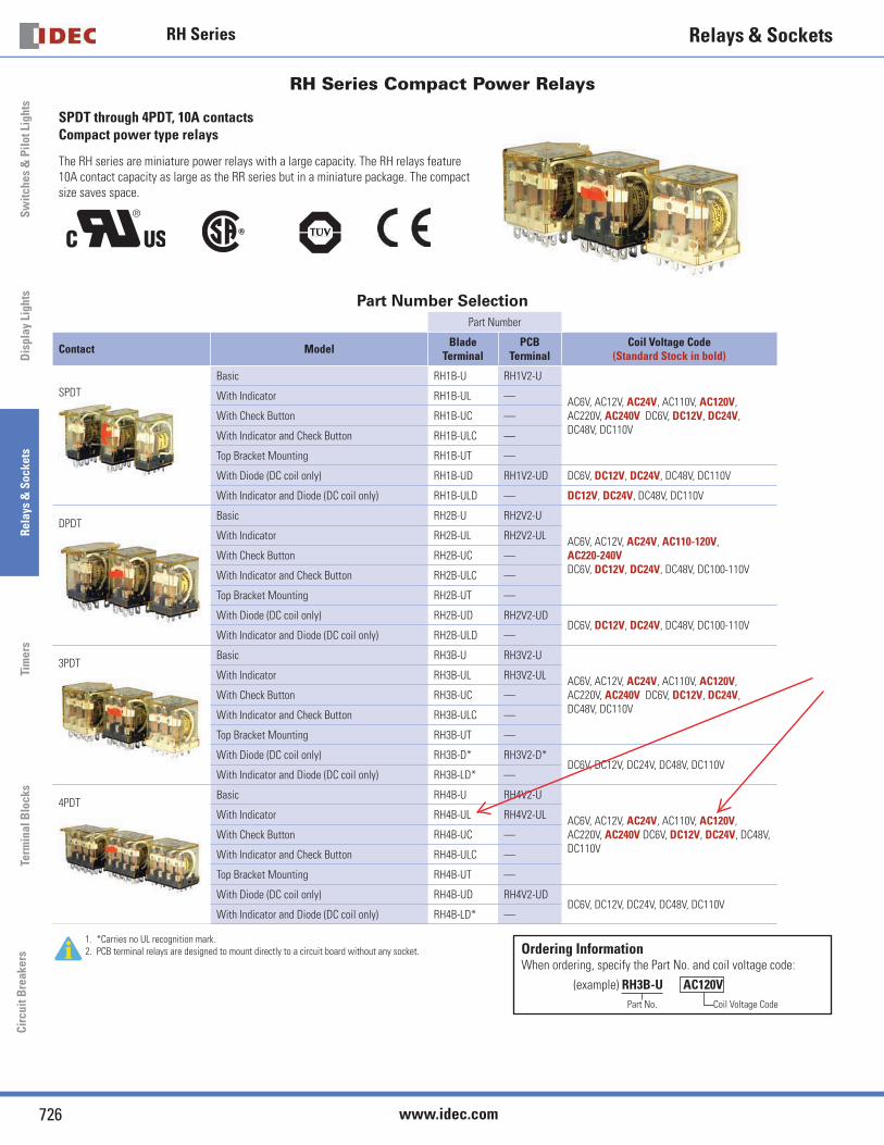
RH Series
726 www.idec.com
Switc
hes
& P
ilot L
ight
sDi
spla
y Li
ghts
Rela
ys &
Soc
kets
Tim
ers
Term
inal
Blo
cks
Circ
uit B
reak
ers
Relays & Sockets
RH Series Compact Power Relays
SPDT through 4PDT, 10A contacts Compact power type relays
The RH series are miniature power relays with a large capacity. The RH relays feature 10A contact capacity as large as the RR series but in a miniature package. The compact size saves space.
""""
Part Number SelectionPart Number
Contact Model Blade Terminal
PCB Terminal
Coil Voltage Code(Standard Stock in bold)
SPDTBasic RH1B-U RH1V2-U
AC6V, AC12V, AC24V, AC110V, AC120V, AC220V, AC240V DC6V, DC12V, DC24V, DC48V, DC110V
With Indicator RH1B-UL —
With Check Button RH1B-UC —
With Indicator and Check Button RH1B-ULC —
Top Bracket Mounting RH1B-UT —
With Diode (DC coil only) RH1B-UD RH1V2-UD DC6V, DC12V, DC24V, DC48V, DC110V
With Indicator and Diode (DC coil only) RH1B-ULD — DC12V, DC24V, DC48V, DC110V
DPDTBasic RH2B-U RH2V2-U
AC6V, AC12V, AC24V, AC110-120V, AC220-240V DC6V, DC12V, DC24V, DC48V, DC100-110V
With Indicator RH2B-UL RH2V2-UL
With Check Button RH2B-UC —
With Indicator and Check Button RH2B-ULC —
Top Bracket Mounting RH2B-UT —
With Diode (DC coil only) RH2B-UD RH2V2-UDDC6V, DC12V, DC24V, DC48V, DC100-110V
With Indicator and Diode (DC coil only) RH2B-ULD —
3PDTBasic RH3B-U RH3V2-U
AC6V, AC12V, AC24V, AC110V, AC120V, AC220V, AC240V DC6V, DC12V, DC24V, DC48V, DC110V
With Indicator RH3B-UL RH3V2-UL
With Check Button RH3B-UC —
With Indicator and Check Button RH3B-ULC —
Top Bracket Mounting RH3B-UT —
With Diode (DC coil only) RH3B-D* RH3V2-D*DC6V, DC12V, DC24V, DC48V, DC110V
With Indicator and Diode (DC coil only) RH3B-LD* —
4PDTBasic RH4B-U RH4V2-U
AC6V, AC12V, AC24V, AC110V, AC120V, AC220V, AC240V DC6V, DC12V, DC24V, DC48V, DC110V
With Indicator RH4B-UL RH4V2-UL
With Check Button RH4B-UC —
With Indicator and Check Button RH4B-ULC —
Top Bracket Mounting RH4B-UT —
With Diode (DC coil only) RH4B-UD RH4V2-UDDC6V, DC12V, DC24V, DC48V, DC110V
With Indicator and Diode (DC coil only) RH4B-LD* —
1. *Carries no UL recognition mark.2. PCB terminal relays are designed to mount directly to a circuit board without any socket. Ordering Information
When ordering, specify the Part No. and coil voltage code: (example) RH3B-U AC120V Part No. Coil Voltage Code

RH Series
727USA: 800-262-IDEC Canada: 888-317-IDEC
Switches &
Pilot LightsDisplay Lights
Relays & Sockets
Timers
Terminal Blocks
Circuit BreakersRelays & Sockets
Sockets (for Blade Terminal Models)Relays Standard DIN Rail Mount 1 Finger-safe DIN Rail Mount 1 Through Panel Mount PCB Mount
RH1B SH1B-05 SH1B-O5C SH1B-51 SH1B-62
1. DIN Rail mount socket comes with two horseshoe clips. Do not use unless you plan to insert pullover wire spring. Replacement horseshoe clip part number is Y778-011.
RH2B SH2B-05 SH2B-05C SH2B-51 SH2B-62
RH3B SH3B-05 SH3B-05C SH3B-51 SH3B-62
RH4B SH4B-05 SH4B-05C SH4B-51 SH4B-62
Hold Down Springs & Clips
Appearance Description Relay For DIN Mount Socket
For Through Panel & PCB Mount Socket Min Order Qty
Pullover Wire Spring
RH1B SY2S-02F1 2
SY4S-51F1 10
2. Must use horseshoe clip when mounting in DIN mount socket. Replacement horseshoe clip part number is Y778-011.
3. Two required per relay.
RH2B SY4S-02F1 2
RH3B SH3B-05F1 2
RH4B SH4B-02F1 2
Leaf Spring (side latch) RH1B, RH2B, RH3B, RH4B SFA-202 3 SFA-302 3
20
Leaf Spring (top latch) RH1B, RH2B, RH3B, RH4B SFA-101 3 SFA-301 3
AC Coil Ratings
Voltage (V)
Rated Current (mA) ±15% at 20°C Coil Resistance (Ω)±10% at 20°C
Operation Characteristics(against rated values at 20ºC)AC 50Hz AC 60Hz
SPDT DPDT 3PDT 4PDT SPDT DPDT 3PDT 4PDT SPDT DPDT 3PDT 4PDT Max. Continuous Applied Voltage
Pickup Voltage
Dropout Voltage
6 170 240 330 387 150 200 280 330 330 9.4 6.4 5.4
110% 80% maximum
30%minimum
12 86 121 165 196 75 100 140 165 165 39.3 25.3 21.2
24 42 60.5 81 98 37 50 70 83 83 153 103 84.5
110 9.6 — 18.1 21.6 8.4 — 15.5 18.2 18.2 — 2,200 1,800
110-120 — 9.4-10.8 — — — 8.0-9.2 — — — — — —
120 8.6 — 16.4 19.5 7.5 — 14.2 16.5 16.5 — 10,800 7,360
220 4.7 — 8.8 10.7 4.1 — 7.7 9.1 9.1 — 10,800 7,360
220-240 — 4.7-5.4 — — — 4.0-4.6 — — 18,820 — —
240 4.9 — 8.2 9.8 4.3 — 7.1 8.3 8.3 — 12,100 9,120
DC Coil Ratings
Voltage (V)
Rated Current (mA) ±15% at 20°C Coil Resistance (Ω)±10% at 20°C
Operation Characteristics(against rated values at 20ºC)
SPDT DPDT 3PDT 4PDT SPDT DPDT 3PDT 4PDT Max. Continuous Applied Voltage
Pickup Voltage
Dropout Voltage
6 128 150 240 250 47 40 25 24
110% 80% maximum
10%minimum
Standard coil voltages are in BOLD.12 64 75 120 125 188 160 100 96
24 32 36.9 60 62 750 650 400 388
48 18 18.5 30 31 2,660 2,600 1,600 1,550
100-110 — 8.2-9.0 — — — 12,250 — —
110 8 — 12.8 15 13,800 — 8,600 7,340
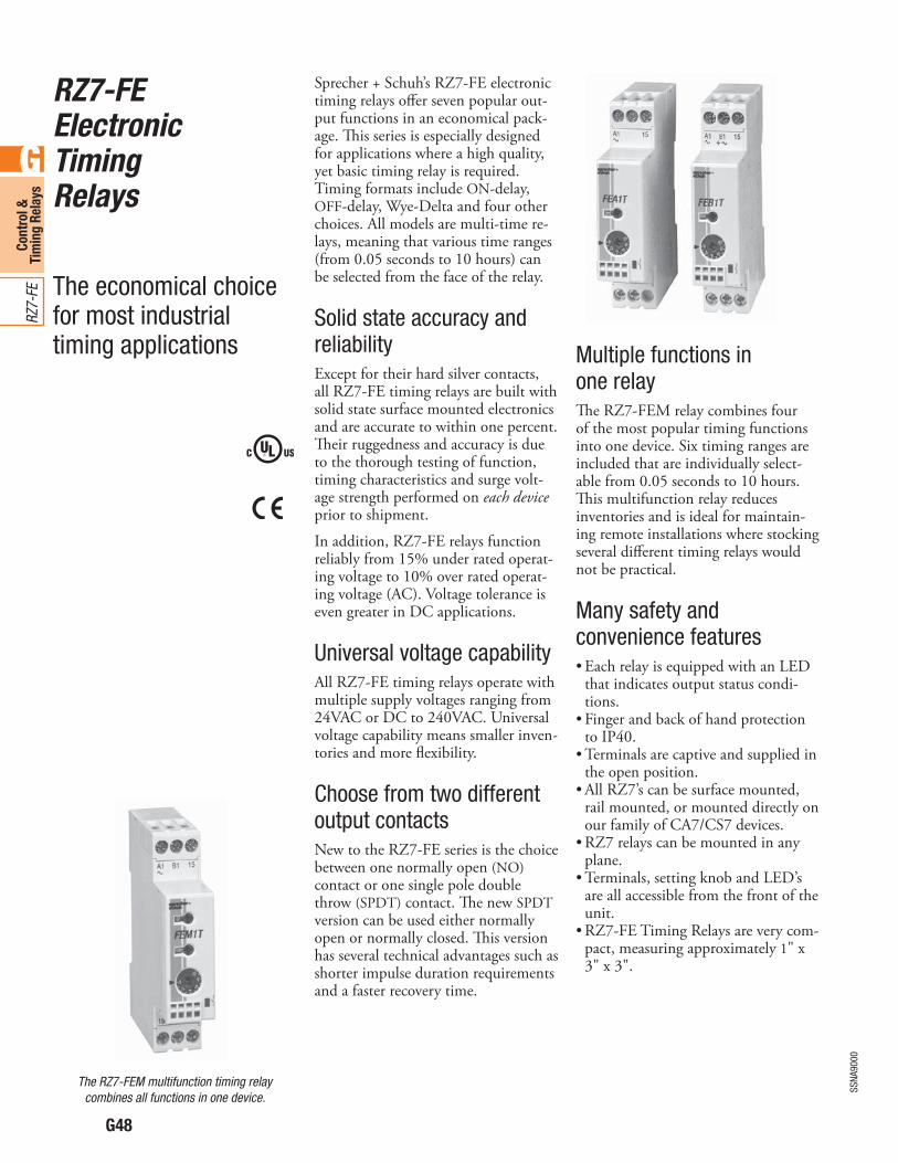
G48
SSNA
9000
G
Cont
rol &
Ti
min
g Re
lays
RZ7-
FE
RZ7-FEElectronicTimingRelays
The economical choice for most industrial timing applications
Sprecher + Schuh’s RZ7-FE electronic timing relays o!er seven popular out-put functions in an economical pack-age. "is series is especially designed for applications where a high quality, yet basic timing relay is required. Timing formats include ON-delay, OFF-delay, Wye-Delta and four other choices. All models are multi-time re-lays, meaning that various time ranges (from 0.05 seconds to 10 hours) can be selected from the face of the relay.
Solid state accuracy and reliabilityExcept for their hard silver contacts, all RZ7-FE timing relays are built with solid state surface mounted electronics and are accurate to within one percent. "eir ruggedness and accuracy is due to the thorough testing of function, timing characteristics and surge volt-age strength performed on each device prior to shipment.In addition, RZ7-FE relays function reliably from 15% under rated operat-ing voltage to 10% over rated operat-ing voltage (AC). Voltage tolerance is even greater in DC applications.
Universal voltage capabilityAll RZ7-FE timing relays operate with multiple supply voltages ranging from 24VAC or DC to 240VAC. Universal voltage capability means smaller inven-tories and more flexibility.
Choose from two different output contactsNew to the RZ7-FE series is the choice between one normally open (NO) contact or one single pole double throw (SPDT) contact. "e new SPDT version can be used either normally open or normally closed. "is version has several technical advantages such as shorter impulse duration requirements and a faster recovery time.
Multiple functions in one relay"e RZ7-FEM relay combines four of the most popular timing functions into one device. Six timing ranges are included that are individually select-able from 0.05 seconds to 10 hours. "is multifunction relay reduces inventories and is ideal for maintain-ing remote installations where stocking several di!erent timing relays would not be practical.
Many safety and convenience features
that indicates output status condi-tions.
to IP40.
the open position.
rail mounted, or mounted directly on our family of CA7/CS7 devices.
plane.
are all accessible from the front of the unit.
-pact, measuring approximately 1" x 3" x 3".
The RZ7-FEM multifunction timing relay combines all functions in one device.
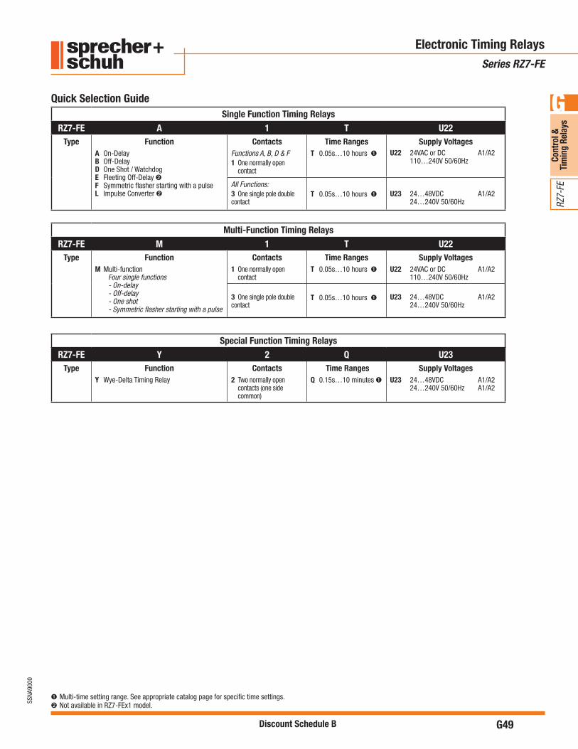
G49
SSNA
9000
G
Cont
rol &
Ti
min
g Re
lays
RZ7-
FE
Discount Schedule B
Electronic Timing RelaysSeries RZ7-FE
➊ Multi-time setting range. See appropriate catalog page for specific time settings. Not available in RZ7-FEx1 model.
Quick Selection GuideSingle Function Timing Relays
RZ7-FE A 1 T U22Type Function
A On-DelayB Off-DelayD One Shot / WatchdogE Fleeting Off-Delay F Symmetric flasher starting with a pulseL Impulse Converter
ContactsFunctions A, B, D & F 1 One normally open contact
Time RangesT 0.05s…10 hours ➊
Supply VoltagesU22 24VAC or DC A1/A2 110…240V 50/60Hz
All Functions: 3 One single pole double contact
T 0.05s…10 hours ➊ U23 24…48VDC A1/A2 24…240V 50/60Hz
Multi-Function Timing RelaysRZ7-FE M 1 T U22
Type FunctionM Multi-function Four single functions - On-delay - Off-delay - One shot - Symmetric flasher starting with a pulse
Contacts1 One normally open contact
Time RangesT 0.05s…10 hours ➊
Supply VoltagesU22 24VAC or DC A1/A2 110…240V 50/60Hz
3 One single pole double contact
T 0.05s…10 hours ➊ U23 24…48VDC A1/A2 24…240V 50/60Hz
Special Function Timing RelaysRZ7-FE Y 2 Q U23
Type FunctionY Wye-Delta Timing Relay
Contacts2 Two normally open
contacts (one side common)
Time RangesQ 0.15s…10 minutes ➊
Supply VoltagesU23 24…48VDC A1/A2 24…240V 50/60Hz A1/A2

G50
SSNA
9000
G
Cont
rol &
Ti
min
g Re
lays
RZ7-
FE
Discount Schedule B
FunctionalDescription
FunctionalDiagram
TerminalArrangement Type Catalog Number Price
ON-Delay Timing Relay (A)When supply voltage is applied, output contact(s) change state after time delay t.
A1/A2Output
LED
t
L/+
A2N/-
A1
18
15
(from 0.05s to 10h) ➋
via wiring terminals A1, A2
RZ7-FEA1TU22 84
A1/A2
A1/B1
Output t
L/+
A2N/-
A1
18
15
16
(from 0.05s to 10h) ➋
accept all appropriate supply voltages
RZ7-FEA3TU23 90
OFF-Delay Timing Relay (B)
contact changes state immediately. When
changes state after time delay t. Constant supply voltage required on terminals A1/A2 or A3/A2.
Note: Control pulse duration minimum 250ms for RZ7-FEB1SU22;50ms (AC) and 30ms (DC) for RZ7-FEB3TU23.
A1/A2
A1/B1Output
LEDt
L/+
A2N/-
A1
18
15B1
➊
(from 0.05s to 10h) ➋
via wiring terminals A1, A2
RZ7-FEB1TU22 90
A1/A2
A1/B1Output
LEDt
L/+
A2N/-
A1 B1
18
15
16
➊
(from 0.05s to 10h) ➋
accept all appropriate supply voltages
RZ7-FEB3TU23 97
One Shot Relay / Watchdog (D)When supply voltage is applied, the output contact changes state for time period t.
A1/A2Output
LEDt
L/+
A2N/-
A1
18
15
(from 0.05s to 10h) ➋
via wiring terminals A1, A2
RZ7-FED1TU22 84
A1/A2
Output
LEDt
L/+
A2N/-
A1
18
15
16
(from 0.05s to 10h) ➋
accept all appropriate supply voltages
RZ7-FED3TU23 90
RZ7-FE Timing Relays – Single Function, One Pole
Electronic Timing RelaysSeries RZ7-FE
Supply VoltageThe last three digits in the catalog number represent the supply voltage range the relay will accept:
U22 24V AC or DC (A1/A2)
110…240V 50/60Hz (A1/A2)
U23 24…48VDC and 24…240V 50/60Hz (A1/A2)
Bicolored LED-
tion:
➊ For timing control, a voltage other than the supply voltage can also be used.➋ Timing range is screwdriver selectable from the faceplate.
RZ7-FE timing relay
RZ7-FE0.05…1 sec0.5…10 sec0.05…1 min0.5…10 min0.05…1 hour0.5…10 hour
Timing Range Codes

SECTION 7
PILOT DEVICES
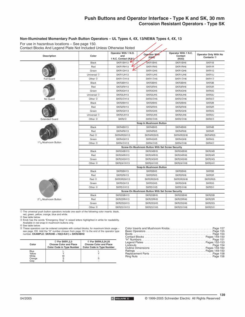
Push Buttons and Operator Interface - Type K and SK, 30 mmCorrosion Resistant Operators - Type SK
13904/2005 © 1999-2005 Schneider Electric All Rights Reserved
Non-Illuminated Momentary Push Button Operators – UL Types 4, 4X, 13/NEMA Types 4, 4X, 13For use in hazardous locations – See page 150.Contact Blocks And Legend Plate Not Included Unless Otherwise Noted
Description ColorOperator With 1 N.O.
and1 N.C. Contact (KA1)
Operator With (KA2)
Operator With 1 N.C. Contact(KA3)
Operator Only With No Contacts !
Full Guard
Black SKR1BH13 SKR1BH5 SKR1BH6 SKR1B
Red SKR1RH13 SKR1RH5 SKR1RH6 SKR1R
Green SKR1GH13 SKR1GH5 SKR1GH6 SKR1G
Universal " SKR1UH13 SKR1UH5 SKR1UH6 SKR1U
Other # SKR1#H13 SKR1#H5 SKR1#H6 SKR1#
No Guard
Black SKR3BH13 SKR3BH5 SKR3BH6 SKR3B
Red SKR3RH13 SKR3RH5 SKR3RH6 SKR3R
Green SKR3GH13 SKR3GH5 SKR3GH6 SKR3G
Universal " SKR3UH13 SKR3UH5 SKR3UH6 SKR3U
Other # SKR3#H13 SKR3#H5 SKR3#H6 SKR3#
Extended Guard
Black SKR2BH13 SKR2BH5 SKR2BH6 SKR2B
Red SKR2RH13 SKR2RH5 SKR2RH6 SKR2R
Green SKR2GH13 SKR2GH5 SKR2GH6 SKR2G
Universal " SKR2UH13 SKR2UH5 SKR2UH6 SKR2U
Other # SKR2# SKR2#H5 SKR2#H6 SKR2#
13/8 Mushroom Button
Snap In Mushroom Button
Black SKR4BH13 SKR4BH5 SKR4BH6 SKR4B
Red SKR4RH13 SKR4RH5 SKR4RH6 SKR4R
Red $ SKR4R05H13 SKR4R05H5 SKR4R05H6 SKR4R05
Green SKR4GH13 SKR4GH5 SKR4GH6 SKR4G
Other % SKR4%H13 SKR4%H5 SKR4%H6 SKR4%
Screw-On Mushroom Button With Set Screw Security
Black SKR24BH13 SKR24BH5 SKR24BH6 SKR24B
Red SKR24RH13 SKR24RH5 SKR24RH6 SKR24R
Green SKR24GH13 SKR24GH5 SKR24GH6 SKR24G
Other % SKR24%H13 SKR24%H5 SKR24%H6 SKR24%
21/4 Mushroom Button
Snap-In Mushroom Button
Black SKR5BH13 SKR5BH5 SKR5BH6 SKR5B
Red SKR5RH13 SKR5RH5 SKR5RH6 SKR5R
Red $ SKR5R05H13 SKR5R05H5 SKR5R05H6 SKR5R05
Green SKR5GH13 SKR5GH5 SKR5GH6 SKR5G
Other % SKR5%H13 SKR5%H5 SKR5%H6 SKR5%
Screw-On Mushroom Button With Set Screw Security
Black SKR25BH13 SKR25BH5 SKR25BH6 SKR25B
Red SKR25RH13 SKR25RH5 SKR25RH6 SKR25R
Green SKR25GH13 SKR25GH5 SKR25GH6 SKR25G
Other % SKR25%H13 SKR25%H5 SKR25%H6 SKR25%
" The universal push button operators include one each of the following color inserts: black,red, green, yellow, orange, blue and white.
# See table below.$ Knob has the words “Emergency Stop” in raised letters highlighted in white for readability.
Available in red snap-in mushroom buttons only.% See table below.! These operators can be ordered complete with contact blocks, for maximum block usage –
see page 155. Add the “H” number chosen from page 151 to the end of the operator typenumber. EXAMPLE: SKR24B + H2(2-KA1) = SKR24BH2
Color# For SKR1,2,3
Choose Color and Place Color Code in Type Number
% For SKR4,5,24,25Choose Color and Place
Color Code in Type Number
BlueYellowWhiteOrangeGray
LYWSE
LY–S–
Color Inserts and Mushroom Knobs . . . . . . . . . . . . . . . . . . . . . . . . . . . .Page 157Basic Operators . . . . . . . . . . . . . . . . . . . . . . . . . . . . . . . . . . . . . . . . . . .Page 155Boots . . . . . . . . . . . . . . . . . . . . . . . . . . . . . . . . . . . . . . . . . . . . . . . . . . Page 154Contact Blocks . . . . . . . . . . . . . . . . . . . . . . . . . . . . . . . . . . . . . . Pages 149-150“H” Numbers . . . . . . . . . . . . . . . . . . . . . . . . . . . . . . . . . . . . . . . . . . . . . Page 151Legend Plates . . . . . . . . . . . . . . . . . . . . . . . . . . . . . . . . . . . . . . . Pages 152-153Lockouts . . . . . . . . . . . . . . . . . . . . . . . . . . . . . . . . . . . . . . . . . . . . . . . .Page 154Outline Dimensions . . . . . . . . . . . . . . . . . . . . . . . . . . . . . . . . . . . Pages 159-160Ratings . . . . . . . . . . . . . . . . . . . . . . . . . . . . . . . . . . . . . . . . . . . . Pages 149-150Replacement Parts . . . . . . . . . . . . . . . . . . . . . . . . . . . . . . . . . . . . . . . .Page 158Ring Nuts . . . . . . . . . . . . . . . . . . . . . . . . . . . . . . . . . . . . . . . . . . . . . . Page 158
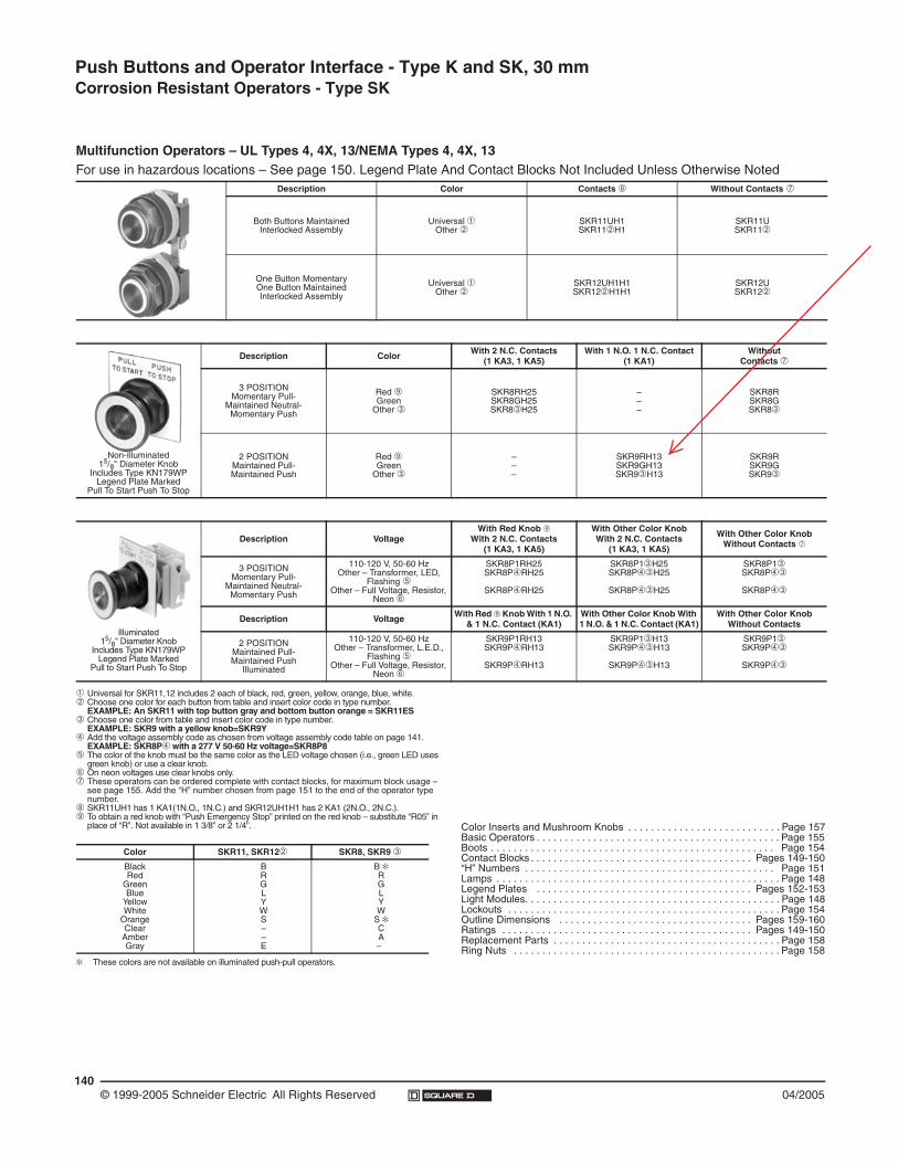
140© 1999-2005 Schneider Electric All Rights Reserved 04/2005
Push Buttons and Operator Interface - Type K and SK, 30 mm Corrosion Resistant Operators - Type SK
Multifunction Operators – UL Types 4, 4X, 13/NEMA Types 4, 4X, 13For use in hazardous locations – See page 150. Legend Plate And Contact Blocks Not Included Unless Otherwise Noted
Description Color Contacts ! Without Contacts "
Both Buttons MaintainedInterlocked Assembly
Universal #Other $
SKR11UH1SKR11$H1
SKR11USKR11$
One Button MomentaryOne Button MaintainedInterlocked Assembly
Universal #Other $
SKR12UH1H1SKR12$H1H1
SKR12USKR12$
Non-Illuminated15/8" Diameter Knob
Includes Type KN179WPLegend Plate Marked
Pull To Start Push To Stop
Description Color With 2 N.C. Contacts(1 KA3, 1 KA5)
With 1 N.O. 1 N.C. Contact (1 KA1)
WithoutContacts "
3 POSITIONMomentary Pull-
Maintained Neutral-Momentary Push
Red %Green
Other &
SKR8RH25SKR8GH25SKR8&H25
–––
SKR8RSKR8GSKR8&
2 POSITIONMaintained Pull-Maintained Push
Red %Green
Other &
–––
SKR9RH13SKR9GH13SKR9&H13
SKR9RSKR9GSKR9&
Illuminated15/8" Diameter Knob
Includes Type KN179WP Legend Plate Marked
Pull to Start Push To Stop
Description VoltageWith Red Knob %
With 2 N.C. Contacts (1 KA3, 1 KA5)
With Other Color Knob With 2 N.C. Contacts
(1 KA3, 1 KA5)
With Other Color Knob Without Contacts "
3 POSITIONMomentary Pull-
Maintained Neutral-Momentary Push
110-120 V, 50-60 HzOther – Transformer, LED,
Flashing 'Other – Full Voltage, Resistor,
Neon (
SKR8P1RH25SKR8P)RH25
SKR8P)RH25
SKR8P1&H25SKR8P)&H25
SKR8P)&H25
SKR8P1&SKR8P)&
SKR8P)&
Description Voltage With Red % Knob With 1 N.O. & 1 N.C. Contact (KA1)
With Other Color Knob With 1 N.O. & 1 N.C. Contact (KA1)
With Other Color Knob Without Contacts
2 POSITIONMaintained Pull-Maintained Push
Illuminated
110-120 V, 50-60 HzOther – Transformer, L.E.D.,
Flashing 'Other – Full Voltage, Resistor,
Neon (
SKR9P1RH13SKR9P)RH13
SKR9P)RH13
SKR9P1&H13SKR9P)&H13
SKR9P)&H13
SKR9P1&SKR9P)&
SKR9P)&
# Universal for SKR11,12 includes 2 each of black, red, green, yellow, orange, blue, white.$ Choose one color for each button from table and insert color code in type number.
EXAMPLE: An SKR11 with top button gray and bottom button orange = SKR11ES& Choose one color from table and insert color code in type number.
EXAMPLE: SKR9 with a yellow knob=SKR9Y) Add the voltage assembly code as chosen from voltage assembly code table on page 141.
EXAMPLE: SKR8P) with a 277 V 50-60 Hz voltage=SKR8P8' The color of the knob must be the same color as the LED voltage chosen (i.e., green LED uses
green knob) or use a clear knob.( On neon voltages use clear knobs only." These operators can be ordered complete with contact blocks, for maximum block usage –
see page 155. Add the “H” number chosen from page 151 to the end of the operator type number.
! SKR11UH1 has 1 KA1(1N.O., 1N.C.) and SKR12UH1H1 has 2 KA1 (2N.O., 2N.C.).% To obtain a red knob with “Push Emergency Stop” printed on the red knob – substitute “R05” in
place of “R”. Not available in 1 3/8” or 2 1/4”.
* These colors are not available on illuminated push-pull operators.
Color SKR11, SKR12$ SKR8, SKR9 &
BlackRed
GreenBlue
YellowWhite
OrangeClear
AmberGray
BRGLYWS––E
B *RGLYW
S *CA–
Color Inserts and Mushroom Knobs . . . . . . . . . . . . . . . . . . . . . . . . . . . Page 157Basic Operators . . . . . . . . . . . . . . . . . . . . . . . . . . . . . . . . . . . . . . . . . . . Page 155Boots . . . . . . . . . . . . . . . . . . . . . . . . . . . . . . . . . . . . . . . . . . . . . . . . . . Page 154Contact Blocks . . . . . . . . . . . . . . . . . . . . . . . . . . . . . . . . . . . . . . . Pages 149-150“H” Numbers . . . . . . . . . . . . . . . . . . . . . . . . . . . . . . . . . . . . . . . . . . . . Page 151Lamps . . . . . . . . . . . . . . . . . . . . . . . . . . . . . . . . . . . . . . . . . . . . . . . . . . Page 148Legend Plates . . . . . . . . . . . . . . . . . . . . . . . . . . . . . . . . . . . . . . Pages 152-153Light Modules. . . . . . . . . . . . . . . . . . . . . . . . . . . . . . . . . . . . . . . . . . . . . Page 148Lockouts . . . . . . . . . . . . . . . . . . . . . . . . . . . . . . . . . . . . . . . . . . . . . . . . Page 154Outline Dimensions . . . . . . . . . . . . . . . . . . . . . . . . . . . . . . . . . . Pages 159-160Ratings . . . . . . . . . . . . . . . . . . . . . . . . . . . . . . . . . . . . . . . . . . . . Pages 149-150Replacement Parts . . . . . . . . . . . . . . . . . . . . . . . . . . . . . . . . . . . . . . . . Page 158Ring Nuts . . . . . . . . . . . . . . . . . . . . . . . . . . . . . . . . . . . . . . . . . . . . . . . Page 158

144© 1999-2005 Schneider Electric All Rights Reserved 04/2005
Push Buttons and Operator Interface - Type K and SK, 30 mm Corrosion Resistant Selector Switches - Type SK
Non-Illuminated 3 Position Selector Switch Operators – UL Types 4, 4X, 13/NEMA Types 4, 4X, 13For use in hazardous locations – See page 150. Legend Plate and Contact Block Not Included Unless Noted
CONTACT BLOCK REQUIRED 1 — Contact Closed 0 — Contact Open
ContactBlock
Position
QuantityandType
Mounton
Side
Center Center Center Center Center Center Center Center Center
Left Right Left Right Left Right Left Right Left Right Left Right Left Right Left Right Left Right
KA1 OR#2
KA3#2 1 0 0 1 0 0 0 0 1 1 0 0 1 0 0 1 0 0 1 0 0 0 1 0 1 1 0
KA2#2 0 1 1 0 0 1 0 1 0 0 1 0 0 0 1 0 1 1 0 1 1 1 0 0 0 0 1
KA1 OR#1
KA3#1 0 0 1 1 0 0 0 0 1 1 0 0 0 1 0 0 0 1 1 0 1 0 0 1 0 1 1
KA2#1 1 1 0 0 0 1 0 1 0 0 1 0 0 0 1 1 0 0 0 1 0 0 1 0 1 0 0
CAM B C D E F G J L M
Non-Illuminated Operators Type Type Type Type Type Type Type Type Type
Manual Return
Operator Only"
Without KnobWith Standard Black KnobWith Other Color Knob (See Table)#
SKS42SKS42BSKS42#
SKS43SKS43BSKS43#
SKS44SKS44BSKS44#
SKS45SKS45BSKS45#
SKS46SKS46BSKS46#
SKS47SKS47BSKS47#
SKS49SKS49BSKS49#
SKS401SKS401BSKS401#
SKS402SKS402BSKS402#
With Contact Block(s)
With Standard Black Knob (See Table for Other Colors, Replace B in Type No. with Color Code)With 1 KA1 on side #2 (H13)With 1 KA1 on side #1 (H1)With 1 KA1 on side #1 and 1 KA1 on side #2 (H2)
SKS42BH13SKS42BH1SKS42BH2
SKS43BH13SKS43BH1SKS43BH2
SKS44BH13SKS44BH1SKS44BH2
SKS45BH13SKS45BH1SKS45BH2
SKS46BH13SKS46BH1SKS46BH2
SKS47BH13SKS47BH1SKS47BH2
SKS49BH13SKS49BH1SKS49BH2
SKS401BH13SKS401BH1SKS401BH2
SKS402BH13SKS402BH1SKS402BH2
Spring Return from
Left to Center
Operator Only"
Without KnobWith Standard Black KnobWith Other Color Knob (See Table)#
SKS62SKS62BSKS62#
SKS63SKS63BSKS63#
SKS64SKS64BSKS64#
SKS65SKS65BSKS65#
SKS66SKS66BSKS66#
SKS67SKS67BSKS67#
SKS69SKS69BSKS69#
SKS601SKS601BSKS601#
SKS602SKS602BSKS602#
Spring Return From
Right to Center
Operator Only"
Without KnobWith Standard Black KnobWith Other Color Knob (See Table)#
SKS72SKS72BSKS72#
SKS73SKS73BSKS73#
SKS74SKS74BSKS74#
SKS75SKS75BSKS75#
SKS76SKS76BSKS76#
SKS77SKS77BSKS77#
SKS79SKS79BSKS79#
SKS701SKS701BSKS701#
SKS702SKS702BSKS702#
Spring Return Both
Sides to Center
Operator Only"
Without KnobWith Standard Black KnobWith Other Color Knob (See Table)#
SKS52SKS52BSKS52#
SKS53SKS53BSKS53#
SKS54SKS54BSKS54#
SKS55SKS55BSKS55#
SKS56SKS56BSKS56#
SKS57SKS57BSKS57#
SKS59SKS59BSKS59#
SKS501SKS501BSKS501#
SKS502SKS502BSKS502#
Top View
Side 2Side 1
Operator LocatingNotch
KA1OR
KA3
KA2
KA1OR
KA3
KA2
Basic Operators . . . . . . . . . . . . . . . . . . . . . . . . . . . . . . . . . . . . . . . . . . .Page 155Boots . . . . . . . . . . . . . . . . . . . . . . . . . . . . . . . . . . . . . . . . . . . . . . . . . . Page 154Contact Blocks . . . . . . . . . . . . . . . . . . . . . . . . . . . . . . . . . . . . . . Pages 149-150“H” Numbers. . . . . . . . . . . . . . . . . . . . . . . . . . . . . . . . . . . . . . . . . . . . . Page 151Legend Plates . . . . . . . . . . . . . . . . . . . . . . . . . . . . . . . . . . . . . . . Pages 152-153Lockouts . . . . . . . . . . . . . . . . . . . . . . . . . . . . . . . . . . . . . . . . . . . . . . . .Page 154Outline Dimensions . . . . . . . . . . . . . . . . . . . . . . . . . . . . . . . . . . Pages 159-160Ratings . . . . . . . . . . . . . . . . . . . . . . . . . . . . . . . . . . . . . . . . . . . . Pages 149-150Replacement Parts . . . . . . . . . . . . . . . . . . . . . . . . . . . . . . . . . . . . . . . .Page 158Ring Nuts . . . . . . . . . . . . . . . . . . . . . . . . . . . . . . . . . . . . . . . . . . . . . . .Page 158Cams . . . . . . . . . . . . . . . . . . . . . . . . . . . . . . . . . . . . . . . . . . . . . . . . . . .Page 157
" These operators can be ordered complete with contact blocks, for maximum block usage – see page 155. Add the “H” number chosen from page 151 to the end of the operator type number.EXAMPLE: SKS43FB+H13(KA1-POS 2) = SKS43FBH13.
# Add the color code as chosen from knob color table below.EXAMPLE: SKS43# with a green gloved hand knob = SKS43FG.
Selector Switch Knobs
Color
StandardKnob
GlovedHand Knob
CoinOperated
#KnobCode
Type#
KnobCode
Type#
KnobCode
Type
BlackRed
GreenYellowOrange
BlueWhiteAmberClear
BRGYSLWAC
B11R8G8Y8
S11L8W8A8C8
FBFRFGFYFSFLFWFAFC
B25R24G24Y24S25L24W24A24C24
TBTRTGTY–
TL––
TC
B18R16G16Y16
–L16––
C16
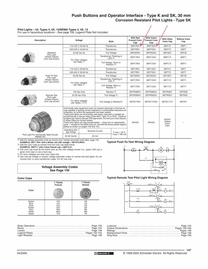
Push Buttons and Operator Interface - Type K and SK, 30 mmCorrosion Resistant Pilot Lights - Type SK
14704/2005 © 1999-2005 Schneider Electric All Rights Reserved
Pilot Lights – UL Types 4, 4X, 13/NEMA Types 4, 4X, 13For use in hazardous locations – See page 150. Legend Plate Not Included.
Description Voltage Style
With Red Fresnel Color
Cap
With Green Fresnel Color
Cap
With Other Color Cap
Without Color Cap
StandardPilot Light
(Plastic fresnel color cap shown)
110-120 V, 50-60 Hz Transformer SKP1R31 SKP1G31 SKP1# SKP1
220-240 V, 50-60 Hz Transformer SKP7R31 SKP7G31 SKP7# SKP7
24-28 Vac-dc Full Voltage SKP35R31 SKP35G31 SKP35# SKP35
For other voltagessee Table "
Transformer, Flashing or LED $ SKP"R31 SKP"G31 SKP"# SKP"
Full Voltage, Neon or Resistor % SKP"R31 SKP"G31 SKP"# SKP"
Push-To-TestPilot Light
(Plastic fresnel color cap shown)
110-120 V, 50-60 Hz Transformer SKT1R31 SKT1G31 SKT1# SKT1
220-240 V, 50-60 Hz Transformer SKT7R31 SKT7G31 SKT7# SKT7
24-28 Vac-dc Full Voltage SKT35R31 SKT35G31 SKT35# SKT35
For other voltagessee Table "
Transformer, Flashing or LED $ SKT"R31 SKT"G31 SKT"# SKT"
Full Voltage, Neon or Resistor % SKT"R31 SKT"G31 SKT"# SKT"
Remote TestPilot Light
(Plastic fresnel color cap shown)
120 Vac Only Resistor ! SKTR38R31 SKTR38G31 SKTR38# SKTR38
24-28 Vac Only Full Voltage ! SKTR35R31 SKTR35G31 SKTR35# SKTR35
For other voltagessee Tables "#! Full Voltage or Resistor! SKTR"R31 SKTR"!G31 SKTR"#! SKTR"
Pilot Light For Intrinsically Safe Circuits(NEMA 4X)
Intrinsically safe equipment must not release electrical or thermal en-ergy capable of igniting certain explosive or combustible hazardous at-mosphere, for which the equipment has been tested.These pilot lights are intrinsically safe when used with a suitable ap-proved barrier or barrier relay (Class 8501 Type TO or NY2). These pi-lot lights are Factory Mutual (FM approved). Consult your local Square D Sales Office for further details.These pilot lights are fully encapsulated — there are no replaceable parts — except for the SK40 ring nut. Use KN100 series plastic legend plates as shown on pages 152 and 153
KP44R KP44GKP44Y(YellowColorCap)
–
Operating Volt-age Range Nominal Current
V max = 32 VI max = 165 mA
20-30 Vac/dc 25 mA
Typical Push-To-Test Wiring Diagram
Typical Remote Test Pilot Light Wiring Diagram
Lockouts . . . . . . . . . . . . . . . . . . . . . . . . . . . . . . . . . . . . . . . . . . . . . . . . Page 154Outline Dimensions . . . . . . . . . . . . . . . . . . . . . . . . . . . . . . . . . . Pages 159-160Ratings . . . . . . . . . . . . . . . . . . . . . . . . . . . . . . . . . . . . . . . . . . . . . . . . Pages 148Replacement Parts . . . . . . . . . . . . . . . . . . . . . . . . . . . . . . . . . . . . . . . Page 158Ring Nuts . . . . . . . . . . . . . . . . . . . . . . . . . . . . . . . . . . . . . . . . . . . . . . . Page 158
R
MM O.L.
L2
321
L1
STOPSTART
L2
C
Test
L1
M
STOP
LSI
M3
(TEST) C
(TEST) C L2
L2
L1(SIG)
CR
M2
M1
L2(TEST) C
START
TEST BUTTONL1 L2
L1(SIG)
L1(SIG)
" Add the voltage assembly code as chosen from voltage assembly code table, page 145.EXAMPLE: SKT"R31 with a 60Vac red LED voltage = SKT37LRR31.
# Add the color code as chosen from the color cap table below.EXAMPLE: SKP1# with a blue fresnel cap = SKP1L31.
$ The color cap must be the same color as the LED voltage chosen (i.e., green LED use agreen color cap) or use a clear cap.
% On neon voltages use clear color caps only.! Use only full voltage or resistor voltage assembly codes on remote test pilot lights. Do not
choose LED, or neon transformer codes. For AC use only.
Basic Operators . . . . . . . . . . . . . . . . . . . . . . . . . . . . . . . . . . . . . . . . . . Page 155Boots . . . . . . . . . . . . . . . . . . . . . . . . . . . . . . . . . . . . . . . . . . . . . . . . . . Page 154Lamps . . . . . . . . . . . . . . . . . . . . . . . . . . . . . . . . . . . . . . . . . . . . . . . . . . Page 148Legend Plates . . . . . . . . . . . . . . . . . . . . . . . . . . . . . . . . . . . . . . . Pages 152-153Light Modules . . . . . . . . . . . . . . . . . . . . . . . . . . . . . . . . . . . . . . . . . . . . Page 148
Color Caps
Color
# PlasticFresnel
# PlasticDomed
AmberBlueClearGreenRed
WhiteYellow
A31L31C31G31R31W31Y31
A9L9C9G9R9W9Y9
Voltage Assembly Codes See Page 145
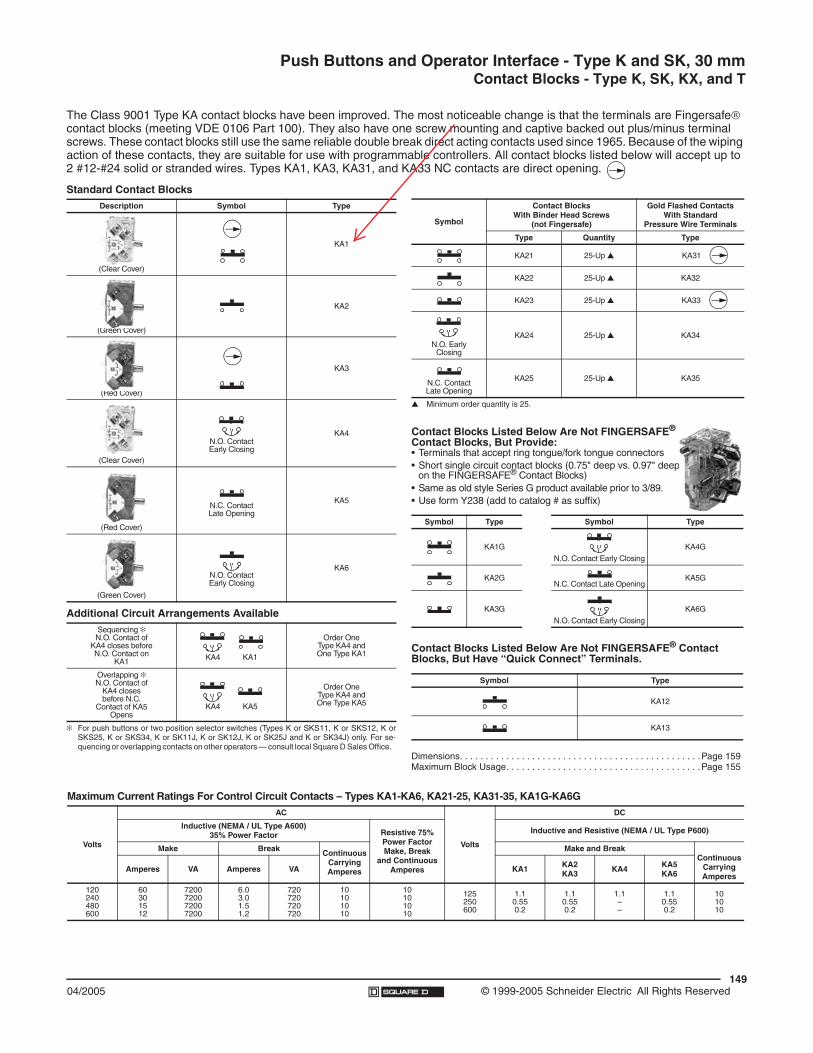
Push Buttons and Operator Interface - Type K and SK, 30 mmContact Blocks - Type K, SK, KX, and T
14904/2005 © 1999-2005 Schneider Electric All Rights Reserved
& For push buttons or two position selector switches (Types K or SKS11, K or SKS12, K orSKS25, K or SKS34, K or SK11J, K or SK12J, K or SK25J and K or SK34J) only. For se-quencing or overlapping contacts on other operators — consult local Square D Sales Office.
Standard Contact BlocksDescription Symbol Type
(Clear Cover)
KA1
(Green Cover)
KA2
(Red Cover)
KA3
(Clear Cover)
N.O. ContactEarly Closing
KA4
(Red Cover)
N.C. ContactLate Opening
KA5
(Green Cover)
N.O. ContactEarly Closing
KA6
Additional Circuit Arrangements AvailableSequencing &N.O. Contact of
KA4 closes beforeN.O. Contact on
KA1 KA4 KA1
Order OneType KA4 andOne Type KA1
Overlapping &N.O. Contact of
KA4 closesbefore N.C.
Contact of KA5Opens
KA4 KA5
Order OneType KA4 andOne Type KA5
' Minimum order quantity is 25.
Contact Blocks Listed Below Are Not FINGERSAFE®
Contact Blocks, But Provide:• Terminals that accept ring tongue/fork tongue connectors• Short single circuit contact blocks (0.75" deep vs. 0.97" deep
on the FINGERSAFE® Contact Blocks)• Same as old style Series G product available prior to 3/89. • Use form Y238 (add to catalog # as suffix)
Contact Blocks Listed Below Are Not FINGERSAFE® Contact Blocks, But Have “Quick Connect” Terminals.
Dimensions. . . . . . . . . . . . . . . . . . . . . . . . . . . . . . . . . . . . . . . . . . . . . . .Page 159Maximum Block Usage. . . . . . . . . . . . . . . . . . . . . . . . . . . . . . . . . . . . . .Page 155
Symbol
Contact BlocksWith Binder Head Screws
(not Fingersafe)
Gold Flashed ContactsWith Standard
Pressure Wire Terminals
Type Quantity Type
KA21 25-Up ' KA31
KA22 25-Up ' KA32
KA23 25-Up ' KA33
N.O. EarlyClosing
KA24 25-Up ' KA34
N.C. ContactLate Opening
KA25 25-Up ' KA35
Symbol Type Symbol Type
KA1GN.O. Contact Early Closing
KA4G
KA2GN.C. Contact Late Opening
KA5G
KA3GN.O. Contact Early Closing
KA6G
Symbol Type
KA12
KA13
Maximum Current Ratings For Control Circuit Contacts – Types KA1-KA6, KA21-25, KA31-35, KA1G-KA6G
Volts
AC
Volts
DC
Inductive (NEMA / UL Type A600)35% Power Factor Resistive 75%
Power FactorMake, Break
and ContinuousAmperes
Inductive and Resistive (NEMA / UL Type P600)
Make Break ContinuousCarryingAmperes
Make and Break Continuous
CarryingAmperes
Amperes VA Amperes VA KA1 KA2KA3 KA4 KA5
KA6
120240480600
60301512
7200720072007200
6.03.01.51.2
720720720720
10101010
10101010
125250600
1.10.550.2
1.10.550.2
1.1––
1.10.550.2
101010
The Class 9001 Type KA contact blocks have been improved. The most noticeable change is that the terminals are Fingersafe! contact blocks (meeting VDE 0106 Part 100). They also have one screw mounting and captive backed out plus/minus terminal screws. These contact blocks still use the same reliable double break direct acting contacts used since 1965. Because of the wiping action of these contacts, they are suitable for use with programmable controllers. All contact blocks listed below will accept up to 2 #12-#24 solid or stranded wires. Types KA1, KA3, KA31, and KA33 NC contacts are direct opening.

SECTION 8
TERMINAL BLOCKS / ACCESSORIES

!""#$%&&'''(#!)*+,-.)+"/."(.)0&1$)314"*&5677869
89(86(9689:::;/<*:8:&:8=
>**3?"!2)1<!@"*20,+/A@BA).4:?:CD@7:?:5677869;A*/$*@B*@,+E)20*3@"!/"@"!*@3/"/@$!)'+@,+@"!,$@;F>@F).10*+"@,$@<*+*2/"*3@E2)0@)12@G+A,+*@H/"/A)<(@;A*/$*@E,+3@"!*@.)0#A*"*@3/"/@,+"!*@1$*2I$@3).10*+"/",)+(@G12@J*+*2/A@D*20$@)E@C$*@E)2@F)'+A)/3$@/2*@K/A,3L!""#%&&3)'+A)/3(#!)*+,-.)+"/."(.)0M
>**3?"!2)1<!@"*20,+/A@BA).4N@H)++*.",)+@0*"!)3%:O.2*'@.)++*.",)+N@H2)$$@$*.",)+%@6(87@00P:?:=00PN@QRJ:9=:?:86N@R,3"!%:=(9@00N@H)A)2%:<2/SN@T)1+",+<@"S#*%:UO@5V&W(VN:UO@5V&8V
R!S@B1S@"!,$@#2)31.":D!*@A/2<*@',2,+<@$#/.*@*+/BA*$@"!*@.)++*.",)+@)E@$)A,3@/+3@$"2/+3*3@.)+31.")2$@',"!)1"@E*221A*$N@*K*+@/B)K*@"!*@+)0,+/[email protected])$$
$*.",)+:Q$@'*AA@/$@$/K,+<@$#/.*N@"!*@.)0#/."@3*$,<+@*+/BA*$@1$*2?E2,*+3AS@',2,+<@,+@/@$0/AA@/0)1+"@)E@$#/.*:D!*@01A",?.)+31.")2@.)++*.",)+@)EE*2$@0/-,010@EA*-,B,A,"S@/+3@',2,+<@3*+$,"S:G#",010@$.2*'32,K*2@<1,3/+.*@"!2)1<[email protected])$*3@$.2*'@$!/E"$:D!*@./BA*@*+"2S@E1++*A@*+/BA*$@"!*@1$*@)E@.)+31.")2$@',"!@E*221A*$@/+3@#A/$",.@.)AA/2$@',"!,+@"!*@+)0,+/[email protected])$$@$*.",)+
@:@@:X*S@.)00*2.,/A@3/"/;/.4,+<@1+," 8T,+,010@)23*2@Y1/+","S V6H/"/A)<@#/<* ;/<*@9W@LHZ8?9688M
JD[U
H1$")0@"/2,EE@+10B*2 \V5=]686H)1+"2S@)E@)2,<,+ J^_TQU`
D*.!+,./A@3/"/
J*+*2/AU10B*2@)E@A*K*A$ 8U10B*2@)E@.)++*.",)+$ 9H)A)2 <2/S[+$1A/",+<@0/"*2,/A ;Q[+EA/00/B,A,"[email protected]/$$@/..)23,+<@")@CZ@]7 a6
F,0*+$,)+$R,3"! =(9@00Z*+<"! 7W(W@00b*,<!"@UO@5V&W(V 7W(V@00b*,<!"@UO@5V&8V VV@00
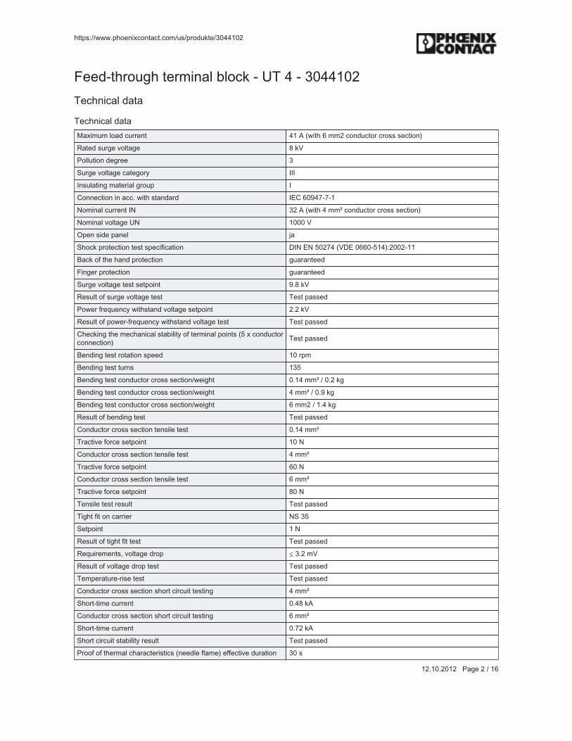
!""#$%&&'''(#!)*+,-.)+"/."(.)0&1$)314"*&5677869
89(86(9689:::;/<*:9:&:8=
>**3?"!2)1<!@"*20,+/A@BA).4:?:CD@7:?:5677869D*.!+,./A@3/"/
D*.!+,./A@3/"/T/-,010@A)/[email protected]*+" 78@Q@L',"!@=@009@.)+31.")[email protected])$$@$*.",)+M_/"*3@$12<*@K)A"/<* \@4a;)AA1",)+@3*<2** 5O12<*@K)A"/<*@./"*<)2S [[[[+$1A/",+<@0/"*2,/A@<2)1# [H)++*.",)+@,+@/..(@',"!@$"/+3/23 [^H@=6]7W?W?8U)0,+/[email protected]*+"@[U 59@Q@L',"!@7@00P@.)+31.")[email protected])$$@$*.",)+MU)0,+/A@K)A"/<*@CU 8666@aG#*+@$,3*@#/+*A c/O!).4@#2)"*.",)+@"*$"@$#*.,E,./",)+ F[U@^U@V69W7@LaF^@6==6?V87M%9669?88d/.4@)E@"!*@!/+3@#2)"*.",)+ <1/2/+"**3>,+<*2@#2)"*.",)+ <1/2/+"**3O12<*@K)A"/<*@"*$"@$*"#),+" ](\@4a_*$1A"@)E@$12<*@K)A"/<*@"*$" D*$"@#/$$*3;)'*2@E2*Y1*+.S@',"!$"/+3@K)A"/<*@$*"#),+" 9(9@4a_*$1A"@)E@#)'*2?E2*Y1*+.S@',"!$"/+3@K)A"/<*@"*$" D*$"@#/$$*3H!*.4,+<@"!*@0*.!/+,./A@$"/B,A,"S@)E@"*20,+/A@#),+"$@LV@-@.)+31.")2.)++*.",)+M D*$"@#/$$*3
d*+3,+<@"*$"@2)"/",)+@$#**3 86@2#0d*+3,+<@"*$"@"12+$ 85Vd*+3,+<@"*$"@.)+31.")[email protected])$$@$*.",)+&'*,<!" 6(87@00P@&@6(9@4<d*+3,+<@"*$"@.)+31.")[email protected])$$@$*.",)+&'*,<!" 7@00P@&@6(]@4<d*+3,+<@"*$"@.)+31.")[email protected])$$@$*.",)+&'*,<!" =@009@&@8(7@4<_*$1A"@)E@B*+3,+<@"*$" D*$"@#/$$*3H)+31.")[email protected])$$@$*.",)+@"*+$,A*@"*$" 6(87@00PD2/.",K*@E)2.*@$*"#),+" 86@UH)+31.")[email protected])$$@$*.",)+@"*+$,A*@"*$" 7@00PD2/.",K*@E)2.*@$*"#),+" =6@UH)+31.")[email protected])$$@$*.",)+@"*+$,A*@"*$" =@00PD2/.",K*@E)2.*@$*"#),+" \6@UD*+$,A*@"*$"@2*$1A" D*$"@#/$$*3D,<!"@E,"@)+@./22,*2 UO@5VO*"#),+" 8@U_*$1A"@)E@",<!"@E,"@"*$" D*$"@#/$$*3_*Y1,2*0*+"$N@K)A"/<*@32)# e@5(9@0a_*$1A"@)E@K)A"/<*@32)#@"*$" D*$"@#/$$*3D*0#*2/"12*?2,$*@"*$" D*$"@#/$$*3H)+31.")[email protected])$$@$*.",)+@$!)2"@.,2.1,"@"*$",+< 7@00PO!)2"?",0*@.122*+" 6(7\@4QH)+31.")[email protected])$$@$*.",)+@$!)2"@.,2.1,"@"*$",+< =@00PO!)2"?",0*@.122*+" 6(W9@4QO!)2"@.,2.1,"@$"/B,A,"S@2*$1A" D*$"@#/$$*3;2))E@)E@"!*20/A@.!/2/."*2,$",.$@L+**3A*@EA/0*M@*EE*.",K*@312/",)+ 56@$

!""#$%&&'''(#!)*+,-.)+"/."(.)0&1$)314"*&5677869
89(86(9689:::;/<*:5:&:8=
>**3?"!2)1<!@"*20,+/A@BA).4:?:CD@7:?:5677869D*.!+,./A@3/"/
D*.!+,./A@3/"/_*$1A"@)E@"!*20/A@"*$" D*$"@#/$$*3D*$"@$#*.,E,./",)+N@)$.,AA/",)+N@B2)/3B/+3@+),$* F[U@^U@V68VV@LaF^@688V?966M%966\?65D*$"@$#*."210 O*2K,.*@A,E*@"*$"@./"*<)2S@[email protected]/$$@dN@)+@K*!,.A*@B)3SD*$"@E2*Y1*+.S E8@f@V@bg@")@E9@f@8V6@bgQOF@A*K*A 6(69@<P&bgQ..*A*2/",)+ 6(\@<D*$"@312/",)+@#*2@/-,$ V@!D*$"@3,2*.",)+$ h?N@`?@/+3@i?/-,$G$.,AA/",)+N@B2)/3B/+3@+),$*@"*$"@2*$1A" D*$"@#/$$*3D*$"@$#*.,E,./",)+N@$!).4@"*$" F[U@^U@V68VV@LaF^@688V?966M%966\?65O!).4@E)20 b/AE?$,+*Q..*A*2/",)+ V@<O!).4@312/",)+ 56@0$U10B*2@)E@$!).4$@#*2@3,2*.",)+ 5D*$"@3,2*.",)+$ h?N@`?@/+3@i?/-,$@L#)$(@/+3@+*<(MO!).4@"*$"@2*$1A" D*$"@#/$$*3D*0#*2/"12*@,+3*-N@,+$1A/",+<@0/"*2,/A@LF[U@^U@=698=?8@LaF^6567?98MM 896@jH
H)++*.",)+@3/"/
U)"* U)"*%@;2)31."@2*A*/$*$N@.)++*.",)[email protected])$$@$*.",)+$@/+3@+)"*$@)+.)++*.",+<@/A10,+10@./BA*$@./+@B*@E)1+3@,+@"!*@3)'+A)/3@/2*/(
H)+31.")[email protected])$$@$*.",)+@$)A,3@0,+( 6(87@00PH)+31.")[email protected])$$@$*.",)+@$)A,3@0/-( =@00PH)+31.")[email protected])$$@$*.",)+@$"2/+3*3@0,+( 6(87@00PH)+31.")[email protected])$$@$*.",)+@$"2/+3*3@0/-( =@00PH)+31.")[email protected])$$@$*.",)+@QRJ&4.0,A@0,+( 9=H)+31.")[email protected])$$@$*.",)+@QRJ&4.0,A@0/- 86H)+31.")[email protected])$$@$*.",)+@$"2/+3*3N@',"!@E*221A*@',"!)1"@#A/$",.$A**K*@0,+( 6(87@00P
H)+31.")[email protected])$$@$*.",)+@$"2/+3*3N@',"!@E*221A*@',"!)1"@#A/$",.$A**K*@0/-( 7@00P
H)+31.")[email protected])$$@$*.",)+@$"2/+3*3N@',"!@E*221A*@',"!@#A/$",.@$A**K*0,+( 6(87@00P
H)+31.")[email protected])$$@$*.",)+@$"2/+3*3N@',"!@E*221A*@',"!@#A/$",.@$A**K*0/-( 7@00P
9@.)+31.")2$@',"!@$/0*@.2)$$@$*.",)+N@$)A,3@0,+( 6(87@00P9@.)+31.")2$@',"!@$/0*@.2)$$@$*.",)+N@$)A,3@0/-( 8(V@00P9@.)+31.")2$@',"!@$/0*@.2)$$@$*.",)+N@$"2/+3*3@0,+( 6(87@00P9@.)+31.")2$@',"!@$/0*@.2)$$@$*.",)+N@$"2/+3*3@0/-( 8(V@00P9@.)+31.")2$@',"!@$/0*@.2)$$@$*.",)+N@$"2/+3*3N@DR[U@E*221A*$',"!@#A/$",.@$A**K*N@0,+( 6(V@00P
9@.)+31.")2$@',"!@$/0*@.2)$$@$*.",)+N@$"2/+3*3N@DR[U@E*221A*$',"!@#A/$",.@$A**K*N@0/-( 9(V@00P
9@.)+31.")2$@',"!@$/0*@.2)$$@$*.",)+N@$"2/+3*3N@E*221A*$@',"!)1"#A/$",.@$A**K*N@0,+( 6(87@00P

!""#$%&&'''(#!)*+,-.)+"/."(.)0&1$)314"*&5677869
89(86(9689:::;/<*:7:&:8=
>**3?"!2)1<!@"*20,+/A@BA).4:?:CD@7:?:5677869D*.!+,./A@3/"/
H)++*.",)+@3/"/9@.)+31.")2$@',"!@$/0*@.2)$$@$*.",)+N@$"2/+3*3N@E*221A*$@',"!)1"#A/$",.@$A**K*N@0/-( 8(V@00P
H)++*.",)+@0*"!)3 O.2*'@.)++*.",)+O"2,##,+<@A*+<"! ]@00[+"*2+/[email protected],+32,./A@</<* Q7O.2*'@"!2*/3 T5D,<!"*+,+<@")2Y1*N@0,+ 6(=@U0D,<!"*+,+<@")2Y1*@0/- 6(\@U0
HA/$$,E,./",)+$
*.A/$$
*HAk$$@7(6 9W878896*HAk$$@7(8 9W878896*HAk$$@V(6 9W878896*HAk$$@V(8 9W878896*HAk$$@=(6 9W878896*HAk$$@W(6 9W878896
*",0
^D[T@9(6 ^H666\]W^D[T@5(6 ^H666\]W^D[T@7(6 ^H666\]W^D[T@V(6 ^H666\]W
1+$#$.
CUO;OH@=(68 56988\88CUO;OH@W(6]68 5]898786CUO;OH@88 5]898786CUO;OH@89(68 5]898786CUO;OH@85(9 5]898786
Q##2)K/A$
Q##2)K/A$
Q##2)K/A$
HOQ@&@CZ@_*.)<+,g*3@&@aF^@2*#)2"@',"!@#2)31.",)+@0)+,")2,+<@&@.CZ@_*.)<+,g*3@&@Z_@&@JZ@&@FUa@&@_O@&@[^H^^@Hd@O.!*0*@&@JGOD@&.CZ1$@_*.)<+,g*3
^-@Q##2)K/A$
[^H^-@&@QD^h
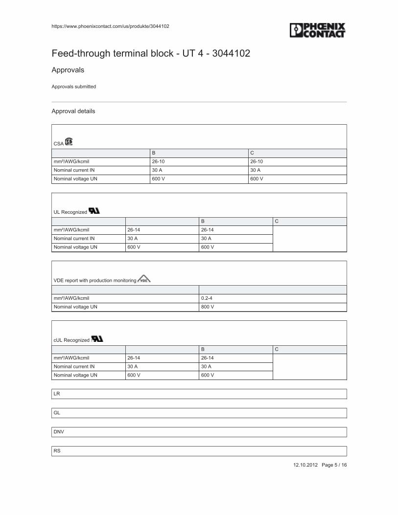
!""#$%&&'''(#!)*+,-.)+"/."(.)0&1$)314"*&5677869
89(86(9689:::;/<*:V:&:8=
>**3?"!2)1<!@"*20,+/A@BA).4:?:CD@7:?:5677869Q##2)K/A$
Q##2)K/A$@$1B0,""*3
Q##2)K/A@3*"/,A$
HOQ:
: d H00P&QRJ&4.0,A 9=?86 9=?86U)0,+/[email protected]*+"@[U 56@Q 56@QU)0,+/A@K)A"/<*@CU =66@a =66@a
CZ@_*.)<+,g*3:
: : d H00P&QRJ&4.0,A 9=?87 9=?87U)0,+/[email protected]*+"@[U 56@Q 56@QU)0,+/A@K)A"/<*@CU =66@a =66@a
aF^@2*#)2"@',"!@#2)31.",)+@0)+,")2,+<:
: :00P&QRJ&4.0,A 6(9?7U)0,+/A@K)A"/<*@CU \66@a
.CZ@_*.)<+,g*3:
: : d H00P&QRJ&4.0,A 9=?87 9=?87U)0,+/[email protected]*+"@[U 56@Q 56@QU)0,+/A@K)A"/<*@CU =66@a =66@a
Z_:
JZ:
FUa:
_O:
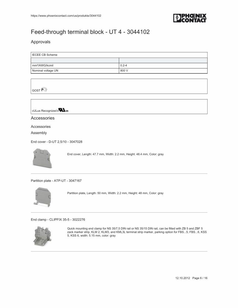
!""#$%&&'''(#!)*+,-.)+"/."(.)0&1$)314"*&5677869
89(86(9689:::;/<*:=:&:8=
>**3?"!2)1<!@"*20,+/A@BA).4:?:CD@7:?:5677869Q##2)K/A$
[^H^^@Hd@O.!*0*:
: :00P&QRJ&4.0,A 6(9?7U)0,+/A@K)A"/<*@CU \66@a
JGOD:
.CZ1$@_*.)<+,g*3:
Q..*$$)2,*$
Q..*$$)2,*$Q$$*0BAS
^+3@.)K*2:?:F?CD@9NV&86:?:567W69\
^+3@.)K*2N@Z*+<"!%:7W(W@00N@R,3"!%:9(9@00N@b*,<!"%:7\(7@00N@H)A)2%:<2/S::
;/2",",)+@#A/"*:?:QD;?CD:?:567W8=W
;/2",",)+@#A/"*N@Z*+<"!%:V6@00N@R,3"!%:9(9@00N@b*,<!"%:7\@00N@H)A)2%:<2/S::
^[email protected]/0#:?:HZ[;>[h@5V?V:?:56999W=
l1,.4@0)1+",+<@*[email protected]/0#@E)2@UO@5V&WNV@F[U@2/,A@)2@UO@5V&8V@F[U@2/,AN@./+@B*@E,""*3@',"!@id@V@/+3@id>@Vg/.4@0/24*2@$"2,#N@XZT@9N@XZT5N@/+3@XTZ5Z@"*20,+/A@$"2,#@0/24*2N@#/24,+<@)#",)+@E)2@>dO(((VN@>dO(((=N@XOOVN@XOO@=N@',3"!%@V(8V@00N@.)A)2%@<2/S
::
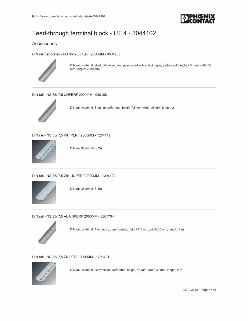
!""#$%&&'''(#!)*+,-.)+"/."(.)0&1$)314"*&5677869
89(86(9689:::;/<*:W:&:8=
>**3?"!2)1<!@"*20,+/A@BA).4:?:CD@7:?:5677869Q..*$$)2,*$
F[U@2/,A@#*2E)2/"*3:?:UO@5V&@WNV@;^_>@9666TT:?:6\68W55
F[U@2/,AN@0/"*2,/A%@$"**A@</AK/+,g*3@/+3@#/$$,K/"*3@',"!@/@"!,.4@A/S*2N@#*2E)2/"*3N@!*,<!"@W(V@00N@',3"!@5V00N@A*+<"!%@9666@00
::
F[U@2/,A:?:UO@5V&@WNV@CU;^_>@9666TT:?:6\68=\8
F[U@2/,AN@0/"*2,/A%@O"**AN@1+#*2E)2/"*3N@!*,<!"@W(V@00N@',3"!@5V@00N@A*+<"!%@9@0::
F[U@2/,A:?:UO@5V&@WNV@Rb@;^_>@9666TT:?:896788]
F[U@2/,A@5V@00@LUO@5VM::
F[U@2/,A:?:UO@5V&@WNV@Rb@CU;^_>@9666TT:?:8967899
F[U@2/,A@5V@00@LUO@5VM::
F[U@2/,A:?:UO@5V&@WNV@QZ@CU;^_>@9666TT:?:6\68W67
F[U@2/,AN@0/"*2,/A%@QA10,+10N@1+#*2E)2/"*3N@!*,<!"@W(V@00N@',3"!@5V@00N@A*+<"!%@9@0::
F[U@2/,A:?:UO@5V&@WNV@iU@;^_>@9666TT:?:896=798
F[U@2/,AN@0/"*2,/A%@J/AK/+,g*3N@#*2E)2/"*3N@!*,<!"@W(V@00N@',3"!@5V@00N@A*+<"!%@9@0::

!""#$%&&'''(#!)*+,-.)+"/."(.)0&1$)314"*&5677869
89(86(9689:::;/<*:\:&:8=
>**3?"!2)1<!@"*20,+/A@BA).4:?:CD@7:?:5677869Q..*$$)2,*$
F[U@2/,A:?:UO@5V&@WNV@iU@CU;^_>@9666TT:?:896=757
F[U@2/,AN@0/"*2,/A%@J/AK/+,g*3N@1+#*2E)2/"*3N@!*,<!"@W(V@00N@',3"!@5V@00N@A*+<"!%@9@0::
F[U@2/,A:?:UO@5V&@WNV@HC@CU;^_>@9666TT:?:6\68W=9
F[U@2/,AN@0/"*2,/A%@H)##*2N@1+#*2E)2/"*3N@!*,<!"@W(V@00N@',3"!@5V@00N@A*+<"!%@9@0::
^+3@./#:?:UO@5V&@WNV@HQ;:?:896=V=6
F[U@2/,A@*+3@#,*.*N@E)2@F[U@2/,A@UO@5V&W(V::
F[U@2/,A@#*2E)2/"*3:?:UO@5V&8V@;^_>@9666TT:?:8968W56
F[U@2/,AN@0/"*2,/A%@$"**A@</AK/+,g*3@/+3@#/$$,K/"*3@',"!@/@"!,.4@A/S*2N@#*2E)2/"*3N@!*,<!"@8V@00N@',3"!@5V00N@A*+<"!%@9666@00
::
F[U@2/,A:?:UO@5V&8V@CU;^_>@9666TT:?:8968W87
F[U@2/,AN@0/"*2,/A%@O"**AN@1+#*2E)2/"*3N@!*,<!"@8V@00N@',3"!@5V@00N@A*+<"!%@9@0::
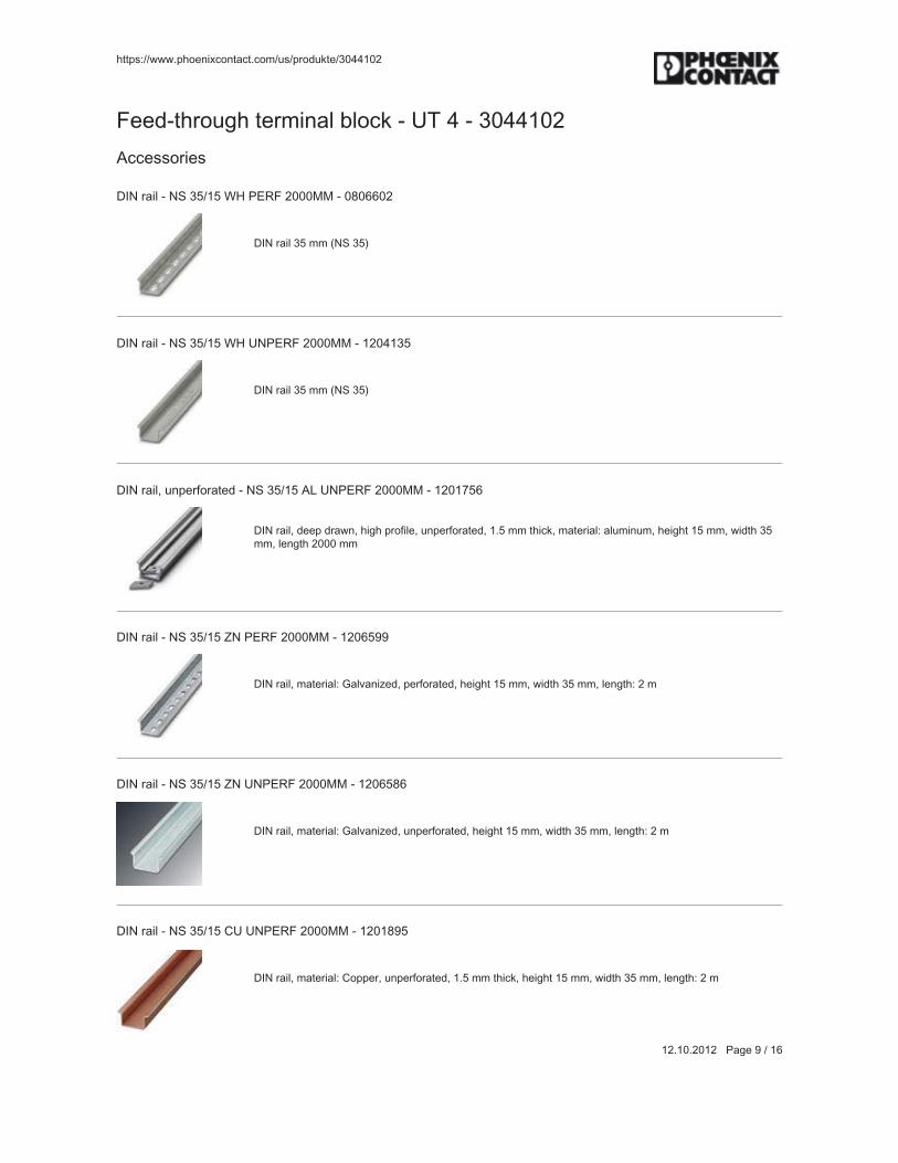
!""#$%&&'''(#!)*+,-.)+"/."(.)0&1$)314"*&5677869
89(86(9689:::;/<*:]:&:8=
>**3?"!2)1<!@"*20,+/A@BA).4:?:CD@7:?:5677869Q..*$$)2,*$
F[U@2/,A:?:UO@5V&8V@Rb@;^_>@9666TT:?:6\6==69
F[U@2/,A@5V@00@LUO@5VM::
F[U@2/,A:?:UO@5V&8V@Rb@CU;^_>@9666TT:?:896785V
F[U@2/,A@5V@00@LUO@5VM::
F[U@2/,AN@1+#*2E)2/"*3:?:UO@5V&8V@QZ@CU;^_>@9666TT:?:8968WV=
F[U@2/,AN@3**#@32/'+N@!,<!@#2)E,A*N@1+#*2E)2/"*3N@8(V@00@"!,.4N@0/"*2,/A%@/A10,+10N@!*,<!"@8V@00N@',3"!@5V00N@A*+<"!@9666@00
::
F[U@2/,A:?:UO@5V&8V@iU@;^_>@9666TT:?:896=V]]
F[U@2/,AN@0/"*2,/A%@J/AK/+,g*3N@#*2E)2/"*3N@!*,<!"@8V@00N@',3"!@5V@00N@A*+<"!%@9@0::
F[U@2/,A:?:UO@5V&8V@iU@CU;^_>@9666TT:?:896=V\=
F[U@2/,AN@0/"*2,/A%@J/AK/+,g*3N@1+#*2E)2/"*3N@!*,<!"@8V@00N@',3"!@5V@00N@A*+<"!%@9@0::
F[U@2/,A:?:UO@5V&8V@HC@CU;^_>@9666TT:?:8968\]V
F[U@2/,AN@0/"*2,/A%@H)##*2N@1+#*2E)2/"*3N@8(V@00@"!,.4N@!*,<!"@8V@00N@',3"!@5V@00N@A*+<"!%@9@0::
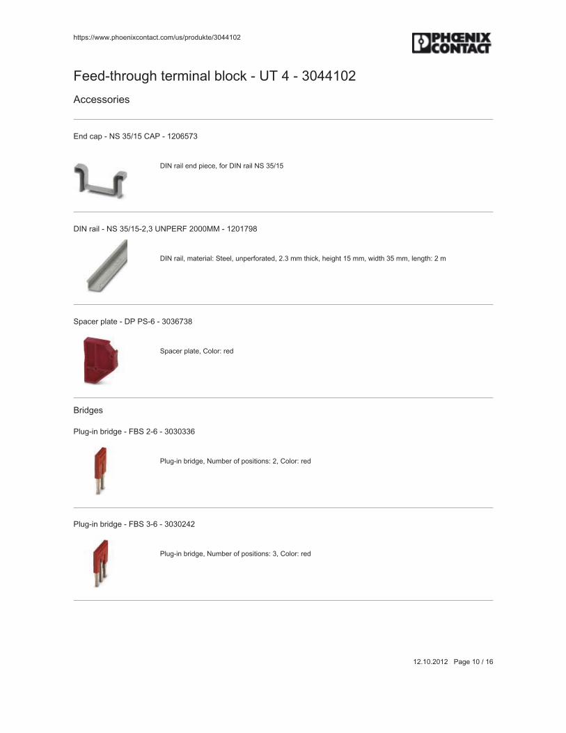
!""#$%&&'''(#!)*+,-.)+"/."(.)0&1$)314"*&5677869
89(86(9689:::;/<*:86:&:8=
>**3?"!2)1<!@"*20,+/A@BA).4:?:CD@7:?:5677869Q..*$$)2,*$
^+3@./#:?:UO@5V&8V@HQ;:?:896=VW5
F[U@2/,A@*+3@#,*.*N@E)2@F[U@2/,A@UO@5V&8V::
F[U@2/,A:?:UO@5V&8V?9N5@CU;^_>@9666TT:?:8968W]\
F[U@2/,AN@0/"*2,/A%@O"**AN@1+#*2E)2/"*3N@9(5@00@"!,.4N@!*,<!"@8V@00N@',3"!@5V@00N@A*+<"!%@9@0::
O#/.*2@#A/"*:?:F;@;O?=:?:565=W5\
O#/.*2@#A/"*N@H)A)2%:2*3::
d2,3<*$
;A1<?,+@B2,3<*:?:>dO@9?=:?:565655=
;A1<?,+@B2,3<*N@U10B*2@)E@#)$,",)+$%:9N@H)A)2%:2*3::
;A1<?,+@B2,3<*:?:>dO@5?=:?:5656979
;A1<?,+@B2,3<*N@U10B*2@)E@#)$,",)+$%:5N@H)A)2%:2*3::

!""#$%&&'''(#!)*+,-.)+"/."(.)0&1$)314"*&5677869
89(86(9689:::;/<*:88:&:8=
>**3?"!2)1<!@"*20,+/A@BA).4:?:CD@7:?:5677869Q..*$$)2,*$
;A1<?,+@B2,3<*:?:>dO@7?=:?:56569VV
;A1<?,+@B2,3<*N@U10B*2@)E@#)$,",)+$%:7N@H)A)2%:2*3::
;A1<?,+@B2,3<*:?:>dO@V?=:?:565657]
;A1<?,+@B2,3<*N@U10B*2@)E@#)$,",)+$%:VN@H)A)2%:2*3::
;A1<?,+@B2,3<*:?:>dO@86?=:?:56569W8
;A1<?,+@B2,3<*N@U10B*2@)E@#)$,",)+$%:86N@H)A)2%:2*3::
;A1<?,+@B2,3<*:?:>dO@96?=:?:56565=V
;A1<?,+@B2,3<*N@U10B*2@)E@#)$,",)+$%:96N@H)A)2%:2*3::
;A1<?,+@B2,3<*:?:>dO@V6?=:?:5659997
;A1<?,+@B2,3<*N@U10B*2@)E@#)$,",)+$%:V6N@H)A)2%:2*3::
T/24,+<

!""#$%&&'''(#!)*+,-.)+"/."(.)0&1$)314"*&5677869
89(86(9689:::;/<*:89:&:8=
>**3?"!2)1<!@"*20,+/A@BA).4:?:CD@7:?:5677869Q..*$$)2,*$
T/24*2@#*+:?:h?;^U@6N5V:?:6\8899\
T/24*2@#*+@',"!)1"@,+4@./2"2,3<*N@E)2@0/+1/A@A/B*A,+<@)E@0/24*2$N@A/B*A,+<@*-"2*0*AS@',#*?#2))EN@A,+*"!,.4+*$$@6(5V@00
::
R/2+,+<@A/B*A:?:RO@CD@7:?:567W559
R/2+,+<@$,<+@E)2@CD@"*20,+/A@BA).4$::
i/.4@0/24*2@$"2,#:?:id@=%CUd^F_CHXD:?:86V8665
i/.4@0/24*2@$"2,#N@O"2,#N@'!,"*N@C+A/B*A*3N@H/+@B*@A/B*A*3@',"!%@;A)""*2N@T)1+",+<@"S#*%@O+/#@,+")@"/AA@0/24*2<2))K*N@>)2@"*20,+/A@BA).4@',3"!%@=(9@00N@Z*""*2,+<@E,*A3%@=(8V@-@86(V@00
::
i/.4@0/24*2@$"2,#:?:id@=@HCO:?:6\97]]9
i/.4@0/24*2@$"2,#N@H/+@B*@)23*2*3%@O"2,#N@'!,"*N@Z/B*A*3@/..)23,+<@")@.1$")0*2@$#*.,E,./",)+$N@T)1+",+<"S#*%@O+/#@,+")@"/AA@0/24*2@<2))K*N@>)2@"*20,+/A@BA).4@',3"!%@=(9@00N@Z*""*2,+<@E,*A3%@=(8V@-@86(V@00
::
T/24*2@E)2@"*20,+/A@BA).4$:?:CH?DT@=:?:6\8\6\V
T/24*2@E)2@"*20,+/A@BA).4$N@O!**"N@'!,"*N@C+A/B*A*3N@H/+@B*@A/B*A*3@',"!%@dA1*0/24N@;A)""*2N@T)1+",+<@"S#*%O+/#@,+")@"/AA@0/24*2@<2))K*N@>)2@"*20,+/A@BA).4@',3"!%@=(9@00N@Z*""*2,+<@E,*A3%@V(=@-@86(V@00
::
T/24*2@E)2@"*20,+/A@BA).4$:?:CH?DT@=@HCO:?:6\97V\]
T/24*2@E)2@"*20,+/A@BA).4$N@H/+@B*@)23*2*3%@dS@$!**"N@'!,"*N@Z/B*A*3@/..)23,+<@")@.1$")0*2@$#*.,E,./",)+$NT)1+",+<@"S#*%@O+/#@,+")@"/AA@0/24*2@<2))K*N@>)2@"*20,+/A@BA).4@',3"!%@=(9@00N@Z*""*2,+<@E,*A3%@V(=@-@86(V@00
::
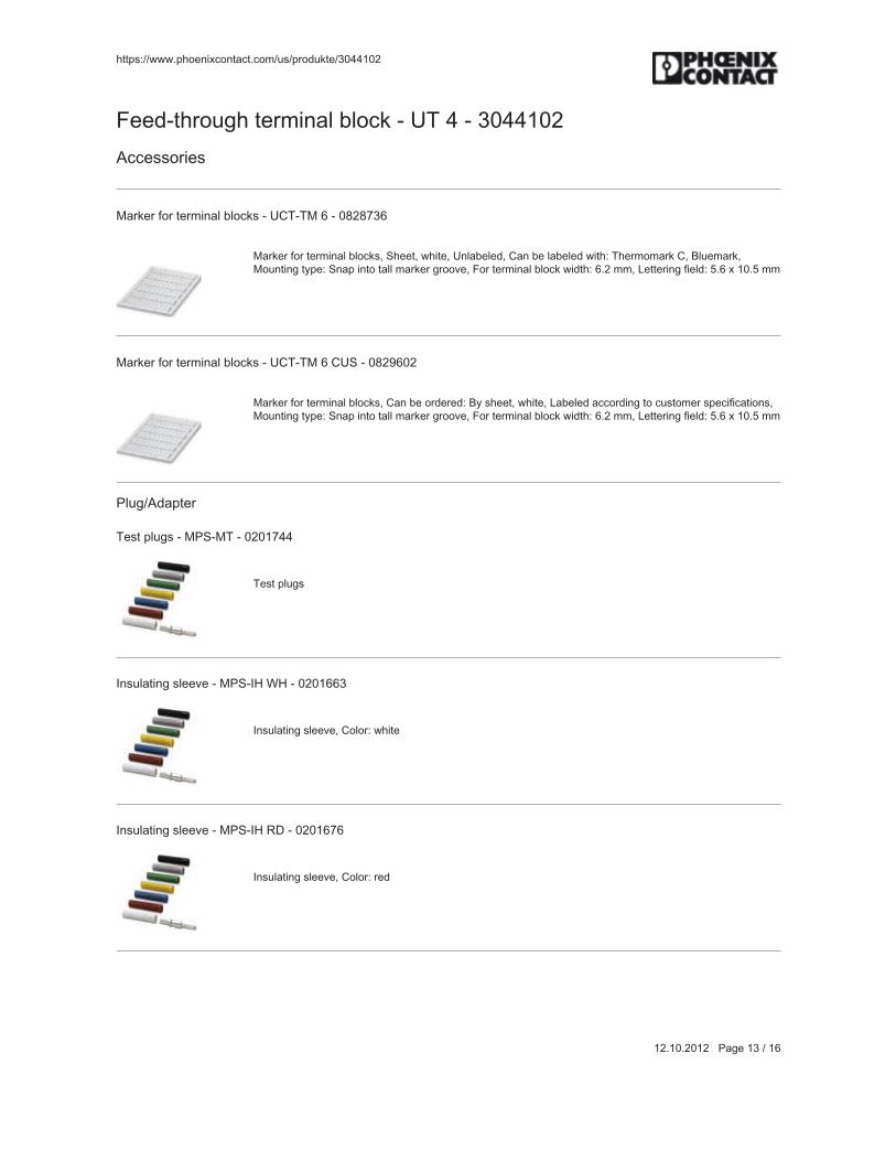
!""#$%&&'''(#!)*+,-.)+"/."(.)0&1$)314"*&5677869
89(86(9689:::;/<*:85:&:8=
>**3?"!2)1<!@"*20,+/A@BA).4:?:CD@7:?:5677869Q..*$$)2,*$
T/24*2@E)2@"*20,+/A@BA).4$:?:CHD?DT@=:?:6\9\W5=
T/24*2@E)2@"*20,+/A@BA).4$N@O!**"N@'!,"*N@C+A/B*A*3N@H/+@B*@A/B*A*3@',"!%@D!*20)0/24@HN@dA1*0/24NT)1+",+<@"S#*%@O+/#@,+")@"/AA@0/24*2@<2))K*N@>)2@"*20,+/A@BA).4@',3"!%@=(9@00N@Z*""*2,+<@E,*A3%@V(=@-@86(V@00
::
T/24*2@E)2@"*20,+/A@BA).4$:?:CHD?DT@=@HCO:?:6\9]=69
T/24*2@E)2@"*20,+/A@BA).4$N@H/+@B*@)23*2*3%@dS@$!**"N@'!,"*N@Z/B*A*3@/..)23,+<@")@.1$")0*2@$#*.,E,./",)+$NT)1+",+<@"S#*%@O+/#@,+")@"/AA@0/24*2@<2))K*N@>)2@"*20,+/A@BA).4@',3"!%@=(9@00N@Z*""*2,+<@E,*A3%@V(=@-@86(V@00
::
;A1<&Q3/#"*2
D*$"@#A1<$:?:T;O?TD:?:6968W77
D*$"@#A1<$::
[+$1A/",+<@$A**K*:?:T;O?[b@Rb:?:6968==5
[+$1A/",+<@$A**K*N@H)A)2%:'!,"*::
[+$1A/",+<@$A**K*:?:T;O?[b@_F:?:6968=W=
[+$1A/",+<@$A**K*N@H)A)2%:2*3::
!""#$%&&'''(#!)*+,-.)+"/."(.)0&1$)314"*&5677869
89(86(9689:::;/<*:87:&:8=
>**3?"!2)1<!@"*20,+/A@BA).4:?:CD@7:?:5677869Q..*$$)2,*$
[+$1A/",+<@$A**K*:?:T;O?[b@dC:?:6968=\]
[+$1A/",+<@$A**K*N@H)A)2%:BA1*::
[+$1A/",+<@$A**K*:?:T;O?[b@`^:?:6968=]9
[+$1A/",+<@$A**K*N@H)A)2%:S*AA)'::
[+$1A/",+<@$A**K*:?:T;O?[b@JU:?:6968W69
[+$1A/",+<@$A**K*N@H)A)2%:<2**+::
[+$1A/",+<@$A**K*:?:T;O?[b@J`:?:6968W9\
[+$1A/",+<@$A**K*N@H)A)2%:<2/S::
[+$1A/",+<@$A**K*:?:T;O?[b@dX:?:6968W58
[+$1A/",+<@$A**K*N@H)A)2%:BA/.4::
D*$"@/3/#"*2:?:;Q[?7?U@J`:?:5659\W8
D*$"@/3/#"*2N@H)A)2%:<2/S::

!""#$%&&'''(#!)*+,-.)+"/."(.)0&1$)314"*&5677869
89(86(9689:::;/<*:8V:&:8=
>**3?"!2)1<!@"*20,+/A@BA).4:?:CD@7:?:5677869Q..*$$)2,*$
D*$"@/3/#"*2:?:;O?=:?:5656]]=
D*$"@/3/#"*2N@H)A)2%:2*3::
O)E"'/2*
O)E"'/2*:?:HZ[;?;_Gm^HD@QFaQUH^F:?:V87=676
T1A",A,+<1/A@$)E"'/2*@E)2@*/$S@#A/++,+<@)E@;!)*+,-@H)+"/."@)+@F[U@2/,A$@")<*"!*2@',"!@"!*@,+"*<2/"*3D_QdD^Hb?$*A*."@$)E"'/2*@0)31A*@E)2@#A/++,+<@.)0#2*!*+$,K*@$12<*@#2)"*.",)+@.)+.*#"$(
::
O)E"'/2*:?:HZ[;?;_Gm^HD@;_G>^OO[GUQZ:?:V87=6V5
T1A",?A,+<1/A@$)E"'/2*@E)2@"*20,+/A@$"2,#@#2)c*."@#A/++,+<(@Q@0/24,+<@0)31A*@/AA)'$@#2)E*$$,)+/A@A/B*A,+<@)E0/24*2$@/+3@A/B*A$@E)2@0/24,+<@"*20,+/A@BA).4$N@.)+31.")2$N@./BA*$@/+3@3*K,.*$(@D!*@/33,",)+/AAS@,+"*<2/"*3$)E"'/2*@0)31A*@D_QdD^Hb?$*A*."@E)2@#A/++,+<@.)0#2*!*+$,K*@$12<*@#2)"*.",)+@.)+.*#"$(
::
D))A$
O.2*'32,K*2:?:OiO@6N=h5NV:?:896V6V5
Q."1/",)+@"))AN@E)2@OD@"*20,+/A@BA).4$N@,+$1A/"*3N@/A$)@$1,"/BA*@E)2@1$*@/$@/@BA/3*3@$.2*'32,K*2N@$,g*%@6(=@-5(V@-@866@00N@9?.)0#)+*+"@<2,#N@',"!@+)+?$A,#@<2,#
::
O.2*'32,K*2:?:O>?OZ@6N=h5NV?866@O?aF^:?:8989V\W
Q."1/",)+@"))AN@E)2@OD@"*20,+/A@BA).4$N@aF^@,+$1A/"*3N@',"!@$A,00*2@,+$1A/",)+@,+"*<2/"*3@,+@"!*@BA/3*N@/A$)$1,"/BA*@E)2@1$*@/$@/@BA/3*3@$.2*'32,K*2N@$,g*%@6(=@-@5(V@-@866@00N@9?.)0#)+*+"@<2,#N@',"!@+)+?$A,#@<2,#
::
F2/',+<$

!""#$%&&'''(#!)*+,-.)+"/."(.)0&1$)314"*&5677869
89(86(9689:::;/<*:8=:&:8=
>**3?"!2)1<!@"*20,+/A@BA).4:?:CD@7:?:5677869H,2.1,"@3,/<2/0
n@;!)*+,-@H)+"/."@9689@?@/AA@2,<!"$@2*$*2K*3!""#%&&'''(#!)*+,-.)+"/."(.)0


