Embed Size (px)
Citation preview

Tools:
Work bench with mounted vise
Drill
3/16" drill bit
Jigsaw or table saw
(4) C-clamps (4-5" span)
Flat metal file

Metal scribe tool or fine tip marker
Metal center punch
Hammer
3 foot metal straight edge or Yard Stick
Tape measure or ruler
Face shield or goggles
Materials:
(1) Youth bow and arrow set (fiberglass limbs at least 1/2" wide limbs and 20" long with 18-25 pound pull)
(You can buy a similar one HERE)
(1) Hard wood to make the Riser (handle grip) use oak, walnut or similar (you can use aluminum if you have a
machine shop and can fabricate this)
(1) Small nail size 2d (2 penny nail) (cut the head off)
(1) Can spray paint (what ever color you decide- optional if you don't want to use paint)
(1) Flat steel stock 1" x 1/16" long enough to make 2 pieces 3 1/2" long
(2) Screws #10-24 x 1 1/2" long (found at LOWES)
(2) Screws #10-24 x 2" long (LOWES)
(4) Wing nuts #10 (LOWES)
(8) Flat washers #10 (LOWES)
(4) Lock washers #10 (LOWES)
Steps:
1. Using a hacksaw, cut off the fiberglass bow limbs where they just meet the hand grip. Ensure both limbs are
the same length after the cuts have been made. Use a file and sand paper to make the lengths the same and
to smooth off the cuts.
2. Measure the width of the limbs and draw a center line going down the center of the limb starting at the cut
end working toward the opposite end. This line only has to be about 5 inches.

3. Look at the diagram and make the measurements for the screw holes. The screw holes in the limbs are the
first holes you want to drill. This gives you a template to drill the other remaining holes in the riser and metal
plates.
4. Place the limbs in a vise and drill the four holes. If you have a table mounted drill and vise, use this as it
gives you a more accurate cut than by doing it free handed.
5. Using the diagram mark the measurements for the riser (hand grip) and cut them out (13"L x 1 1/4"W x
3/4"H). Do not cut the 1/4" angled cut (the one that is shaded) until after the screw holes have been drilled.
6. Next, make the measurements where the limbs are to be mounted to the riser. The cut end of the limb will
go 3 1/2" from each bottom end of the riser as shown in the diagram. Make a mark so that you will know
where to put each limb when it's time for the C-clamps and drilling.
7. Place the riser (bottom side facing up) in the vise (place thin pieces of wood on each side of the riser to
protect it from the jaws of the vise). The jaws of the vise should be in the center of the riser with about 3/4"
of the riser protruding at the top of the vise jaw.
8. Place each limb with the cut ends on the line previously drawn and secure them with two C-clamps for each
end of the limb. Leave room where the holes are to be drilled. Ensured that bow string notch at the opposite
ends of the limbs are facing toward the top of the riser.
9. Place a metal straight edge alongside both limbs from one end to the other and ensure the limbs are
aligned with each other. When the limbs are aligned, you can use the holes, already drilled into the limbs, as a
template. Go ahead and drill the holes into the riser.
10. After the holes in the riser are drilled, put the #10 screws through the riser and limbs to ensure a smooth
matching fit.
11. Measure the shaded angle cut for the riser and cut it out using a jigsaw or similar cutting device. (You do
not have to make this cut if you don't want to. It is for looks only, but you will have to replace the two 1 1/2"
screws with 2- 2" screws.) Sand all the rough edges down using the sandpaper.
12. Measure and cut out the two metal plates. Use the metal file and round of all the sharp angles.
13. Align each metal plate at the cut end of the limbs (bottom side of the limbs). Clamp the plates in place
using the C-clamps, leaving room to mark the holes. Using the holes in the limbs as templates, take a metal
scribe tool or fine tip marker and draw the holes onto the metal plates.
14. Remove the C-clamps and limbs. Using a center punch and hammer, find the center of each hole on the
metal plates and make a mark. This is where the drill bit tip will ride when you drill the holes. The
measurement of these holes needs to be as close to the ones on the limbs as possible so that everything lines
up when putting the bow together. So, measure twice and cut once is the old saying here.

15. Place the metal plates in the vise or drill press if you have one, and drill out each hole. Use the metal file
to file off any remaining burrs from drilling.
16. Find the center of the riser (hand grip) and mark the center point on the side where the arrow sits. Make
sure the center is width wise and length wise. Using the diagram, make the measurements for the nail (6 1/2"
from the end and 3/16" from the bottom upward). Use a drill bit that is one size smaller than the diameter of
the nail and drill down 1/4". Hammer in the 3/4" headless nail until it is in 1/4" of an inch. Pre-drilling the hole
prevents the wood from splitting when hammering in the nail.
17. Put the bow together. Use the limbs and plates on the same ends they were measured for as they may fit
better. Once the bow is together and everything matches up, it is a good idea to mark one end as a set. Take
the metal file and file two hatch marks on the side of one of the metal plates and the top of the limb
associated with the metal plate. I did this for the top limb combo, so when I put the bow together I use the
same set.
18. String the bow and do a test fire.
19. Paint the bow if desired.
20. Make a carrying case for the bow and arrows. (Be creative or use the idea shown on the video)

Tools:
Copper tube cutter
Hacksaw
Small tap and die set
Small hammer
Tape Measure or Yard Stick
Materials:
(3) Aluminum arrows with fletching and tips already attached. (optional if you are not going to make break
down arrows)
(9) Threaded arrow inserts, includes the broad head inserts (inserts must be the size used for the arrow
diameter with the threads being 8-32- look under arrow accessories on internet archery sites or go HERE)
(6) Small rubber O-rings, type used for mounting broad heads to the arrow shaft (look under broad head
accessories on internet archery supply sites, or go HERE)
(1) Tube archery glue or similar (model glue will work)
(3) Threaded rod 8-32 x 2" (LOWES) (these need to be cut to 1 5/16" long)
Steps:
1. Using a tape measure or yard stick, make a mark 20" from the nock end of the arrow toward the broad
head end. This is slightly shorter than the bow limb and will compensate for the addition of the threaded rod.
2. Using a copper tube cutter, cut the arrow at the mark. The cutter should have an attached tool that
removes any burrs from the cutting.
3. If the arrow came with a broad head, then it already has a threaded insert and rubber o-ring, if not you will
need to insert an insert here. At the point where you made the cut, you will need to add an insert at each cut
end. Put a small amount of glue around each threaded insert and put them into the holes. You made need to
use a hammer to tap them until they are fully seated. Clean off any excess glue.
4. Measure and cut the threaded rod to a length of 1 5/16". Thread the rod into the inserts where the cuts
were made. If the cut end of the threaded rod does not screw in smoothly, then you may have to clean the

threads using a tap and die set, or a thread file if you have one. Clean up the threads until both ends can be
screwed into the inserts.
5. The threaded rod will be permanently attached to the lower half of the arrow, so put some glue on the
lower quarter part of the threaded rod and screw into place. Allow the glue to dry.
6. When putting the arrow together, make sure you place an o-ring between the two halves before screwing
them together. This keeps the arrow from coming loose at the threads. Make sure the broad head has an o-
ring as well.
Note: I will be designing a fletching cover for the arrows to protect them when they are stored in the carrier. I
will make a future post update when I have one perfected.
Tip: Put extra parts for your bow in a small candy tin or plastic box. (extra screws, washers, wing nuts, o-rings,
bow string, arrow tips, etc.)

Nov. 19, 1957 B. PEARsoN 2,813,818
METHOD OF MAKING A DEMOUNTABLE BOW
FIG2.
Filed Aug. l, 1955
FIGS. ' F|G.4.
ll5
37
-FlGlog /„
INVENToR, BEN PEARSON
www

July 26, 1966 P. B. GRABLE 3,252,442 TAKE-APART BOW
Filed Sept, 20, 1965 2 Sheets-Sheet l
INVENTOR
P/l/LL/P B. 63/4545
Fi_é_.l._ 57-5-3. BY mywféééa/
ATTORNEYS

July 26, 1966 P‘ B. GRABLE 3,262,442 TAKE-APART BOW
Filed Sept, 20, 1965 2 Sheets-Sheet 2
2o 20
3.:- E _- E .
INVENTOR
ATTORNEYS

United States Patent [191 Karbo
[11 1 3,738,348 [45] June 12, 1973
[54] TAKE-DOWN ARCHERY BOW
[75] Inventor: Richard S. Karbo, Whittier, Calif.
[73] Assignee: Brunswick Corporation, Chicago, Ill. [22] Filed: Feb. 11, 9171
[21] Appl. No.: 114,567
[52] U.S. Cl. ............................ .. 124/24, 273/DIG. 7 [51] Int. Cl. ............................................ .. F41b 5/00 [58] Field of Search ................ .. 124/24, 23, 22, 25,
124/41, 35
[56] References Cited UNITED STATES PATENTS
3,527,196 9/l970 Karbo l . . . . . . . l . . . . . . . . . . . . . . .. 124/20
2,163,503 6/1939 Tate . . . . . . . . . . . . . . . . . . . . . .. 124/23
2,642,661 6/1953 Fredrickson . . . . . . . . . .. 124/23
3,262,442 7/1966 Grable ................................ .. 124/24
Primary Examiner-Richard C. Pinkham Assistant Examiner-William R. Browne Att0rney—D0nald S. Olexa, Sheldon L. Epstein. John G. Heimovics et al..
[ 57] ABSTRACT A take-down archery bow having a pair of bow limbs with stepped interior ends which are adapted to be locked in the mated position by a threaded bolt. The lateral surfaces between the steps has an interengaging ramp and incline combination which interacts to apply a longitudinal force on the bow limbs to draw the stepped ends of the bow limbs together as the bolt draws the lateral surfaces together. A pair of interen gaging boss and cut-out portions are also provided to absorb a portion of the bending loads acting on the limbs.
4 Claims, 5 Drawing Figures


‘a
as} - 1.,
United States Patent [191 Hoyt, Jr. I i -
[111 3,814,075 [451 June 4,1974
[54]
[76]
[22] [21]
[52] [51] [58]
l [561
2,642,66l 3.265.055 3,326,200 3,527.196
TAKE DOWN ARCHERY BOW WITH A MOUNT FOR A BOW STABILIZING ELEMENT '
lnventor: Earl H. Hoyt, Jr., 1 l5 10 Natural Bridge Rd., Bridgeton, Mo. 65617
Filed: July 21, 1972
Appl. No.: 274,095
US. Cl. ........................... .. 124/24 R, 124/30 R Int. Cl. ............................................ .. F4lb 5/00 Field of Search ..... 124/23 R, 24 R, 25, 22,
124/35, 41
References Cited UNlTED STATES PATENTS (3/1953 . Fredrickson .................... 124/23 R 8/l966 Gage ........... 6/l96'7 Grublc .......... ..
9/1970 Karl'm ............................. .. l24/24R
Priniary Examiner—Richard C. Pinkham Assistant Examiner—William R. Browne Attorney, Agent, or Firm—Charles E. Markham
[57] ABSTRACT An archery bow with limbs detachably connected to a handle section. The butt end portions of the limbs are freely entered in close fitting relationship between lon gitudinally spaced forward and rear wall portions of sockets formed in the ends of- the handle section. A ?xed pin extending fore and aft across the bottom of each socket engages a groove in the end of the limb and a short stud projecting from the rear side of each limb parallel with the ?xed pin and spaced from the end of the limb enters a hole in the rear socket wall in close ?tting relationship to position and hold the limbs
, in lateral alignment. A thumb screw extends through the rear wall of each socket and is threadedly engaged in the short projecting studs to clamp the limbs to the rear socket walls. The forward socket walls are shorter than the rear walls and a portion of each rear socket wall near the bottom is relieved to permit entry of the limbs in a slightly forward tilted position thereby to permit free entry of the limbs between the socket wall portions and to permit entry of the short projecting studs. .'
9 Claims, 7 Drawing Figures


‘PATENTEDJUN 4:914 _ ' K 3314.075 4
‘SHEET 2 (IF 2
fl

[75] Inventor: Tadao lzuta, Hamamatsu, Japan [73] Assignee: Nippon Gakki Seizo Kabushiki
Kaisha, l-lamamatsu, Japan [22] Filed: June 20, 1974
[21] Appl. No.: 481,403
[52] US. Cl. ........ .1 .... .-. ........... .. 124/24 R; 124/30 R [51] Int. Cl.2 ............................ ..- ............ .. F4-1B 5/00
[58] Field of Search ...... .. 124/23 R, 24 R, 30 R, 25, 124/22, 30 A, 52; 279/79, 85
[56] References Cited UNITED STATES PATENTS
2,476,762 7/1949 Petre et a1. ..................... .. 279/79 X ~ 2,522,388 9/1950 Madsen . . . . . . . . . . . . . . . . .. 279/79 X
2,562,462 7/1951 Jackson . . . . . . . . . . . . . . . . . . . .. 124/52
2,580,930 1/1952 Kost .................................... .. 279/79
2,958,552 11/1960 Vosbikian et al ............... .. 279/79 X 2,972,493 2/1961 Waters ............................ .. 279/79 X 3,415,240 12/1968 Bear . . . . . . . . . . . . . . . . .. 124/23 R
3,628,519 12/1971 l-lofmeister .................. .. 124/24 R
3,695,248 10/1972 lzuta ............................... .. 124/24 R
'United States Patent [191 [111 3,942,506 lzuta [45] Mar. 9, 1976
[54] DEMOUNTABLE ARCHERY BOW 3,814,075 6/1974 Hoyt ............................... .. 124/24 R
Prim-my Examiner-Anton O. Oechsle Assistant Examiner-William R. Browne Attorney, Agent, or Firm-Haseltine, Lake_& Waters
[57] ABSTRACT A demountable archery bow with a handle provided at the opposite ends thereof with limb receiving means, and limbs to be removably inserted in the respective limb receiving means. A click stop mechanism is pro vided between each limb receiving means and the as sociated limb to facilitate the assembly and disassem bly of the handle and limbs. The click stop mechanism may have a recess formed on the limb side in a man ner to open in a direction perpendicular to that in which the limb is inserted in the limb receiving means, and a spring biased ball provided on the handle side, the ball being received in the recess under the spring biasing force when the limb is inserted in the handle and the ball being forcedly removable from the recess when a force pulling the limb away from the handle is exerted on the limb.
4 Claims, 8 Drawing Figures
T 724

US. Patent March 9, 1976 Sheet 1 of4 3,942,506
FIG. 1

US. Patent March 9, 1976 Sheet20f4 3,942,506
FIG. 5 FIG. 4

US. Patent March 9, 1976 Sheet 3 of4 3,942,506
FIG. 6

US. Patent March 9, 1976 Sheet4 0f4 3,942,506

United States Patent [191 Killian
[11] 4,187,826 [45] Feb. 12, 1980
[54] FOLDING LIMB COMPOUND ARCHERY BOW
[76] Inventor: Gerald I. Killian, 16016 SE. 82nd Dr., Clackamas, Oreg. 97015
[21] Appl. No.: 787,860 [22] Filed: Apr. 15, 1977
[51] Int. Cl.2 . . . . . . . . . . . . . . . . . . .. F41B 5/00
[52] US. Cl. .................................. .. 124/24 R; 29/235; 124/88
[58] Field of Search ................ .. 124/23 R, 24 R, 90, 124/88, 86; 403/12; 24/1226, 135 N, 135 R;
29/235
[56] References Cited
U.S. PATENT DOCUMENTS
3,207,145 9/ 1965 Browning et al. ............... .. 124/23 R 3,253,587 ' 5/ 1966 Pearson .................... .. 124/23 R
3,294,078 12/ 1966 Allen .... .. 124/23 R 3,352,296 11/1967 Burger .. .... .. 124/23 R
3,486,495 12/ 1969 Allen 124/ 24 R 3,841,295 10/1974 Hunter .. .. 124/24 R 3,957,027 5/1976 Drake .... .. 124/23 R 4,050,137 9/ 1977 Carlson ................................ .. 29/235
FOREIGN PATENT DOCUMENTS
708863 7/ 1941 Fed. Rep. of Germany ........ .. 24/ 122.6
Primary Examiner—Richard C. Pinkham
Assistant Examiner—William R. Browne Attorney, Agent, or Firm—James E. Nilles
[57] ABSTRACT A compound archery bow has resilient limbs pivotally attached to the opposite ends of a central handle by hinges allowing the limbs to be folded between an oper ative position and a folded position. The limbs are re leasably secured in an operation position by a latch mechanism. A secondary cable interconnects each limb and a tensioning lever on the handle for adjustably pre-tensioning the limbs. A ratchet shaft assembly piv otally mounts the tensioning levers and allows the ten sion of each limb to be adjusted. The limbs can be re laxed by lengthening a stringer, whereupon the latch mechanism can be opened, allowing the limbs to be released and pivoted on the hinges to their folded posi tion adjacent the belly side of the bow. Cam members are mounted at the outer end of each limb and around which the end segments of the bow string are wrapped at least about 270° in each direction. Thus the cam mem bers can be reversibly rotated to accommodate either tensioning of the bow for projecting an arrow, or relax ing of the bow for release of the limbs. As a result the bow may be folded and unfolded without altering its pre-established tension characteristics.
9 Claims, 12 Drawing Figures

U.S. Patent Feb. 12, 1980
l 6 '
a 88 I10
50 10% 4/
Sheet 1 of 3 4,187,826
_ ' 124
120 "a 1252
750
» 170V
/ 20 /8 I” I / 76 v;

U.S. Patevntv Feb. 12, 1980 Sheet 2 of 3 4,187,826

‘US. Patent Feb. 12, 1980 Sheet 3 of3 ' 4,187,826
N%k. R _________=____

United States Patent [19] Izuta
4,574,766 Mar. 11, 1986
[11] Patent Number:
[45] Date of Patent:
[54] JOINT STRUCTURE OF A TAKE-DOWN TYPE ARCHERY BOWS
[75] Inventor:
[73] Assignee: Tadao Izuta, Hamamatsu, Japan Nippon Gakki Seizo Kabushiki Kaisha, Japan
[21] Appl. N0.: 404,291 [22] Filed: Aug. 2, 1982
[30] Foreign Application Priority Data
Aug. 6, 1981 [JP] Japan ......................... .. 56-117220[U]
[51] Int. Cl.4 .............................................. .. F41B 5/00
[52] US. Cl. ................................ .. 124/23 R; 124/88 [58] Field of Search .......... .. 124/23 R, 24 R, DIG. 1,
‘ 124/88, 86
[56] References Cited
U.S. PATENT DOCUMENTS
261,610 7/1882 Howe .............................. .. 124/23 R
3,262,442 7/1966 Grable 124/24 R 3,415,240 12/1968 Bear ..... .. 124/23 R
3,757,762 9/1973 Cousin 124/24 R 3,766,904 10/1973 Izuta .................... .. 124/24R
3,874,360 4/1975 Armstrong et a]. 124/23 R 3,921,598 11/1975 Helmick .......................... .. 124/24R
3,957,027 5/1976 Drake ............................. .. 124/23R
FOREIGN PATENT DOCUMENTS
114300 lO/l978 Japan .............................. .. 124/23 R
Primary Examiner—Richard J. Apley Assistant Examiner—William R. Browne Attorney, Agent, or Firm—Lerner, David, Littenberg, Krumholz & Mentlik
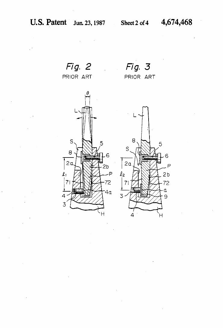
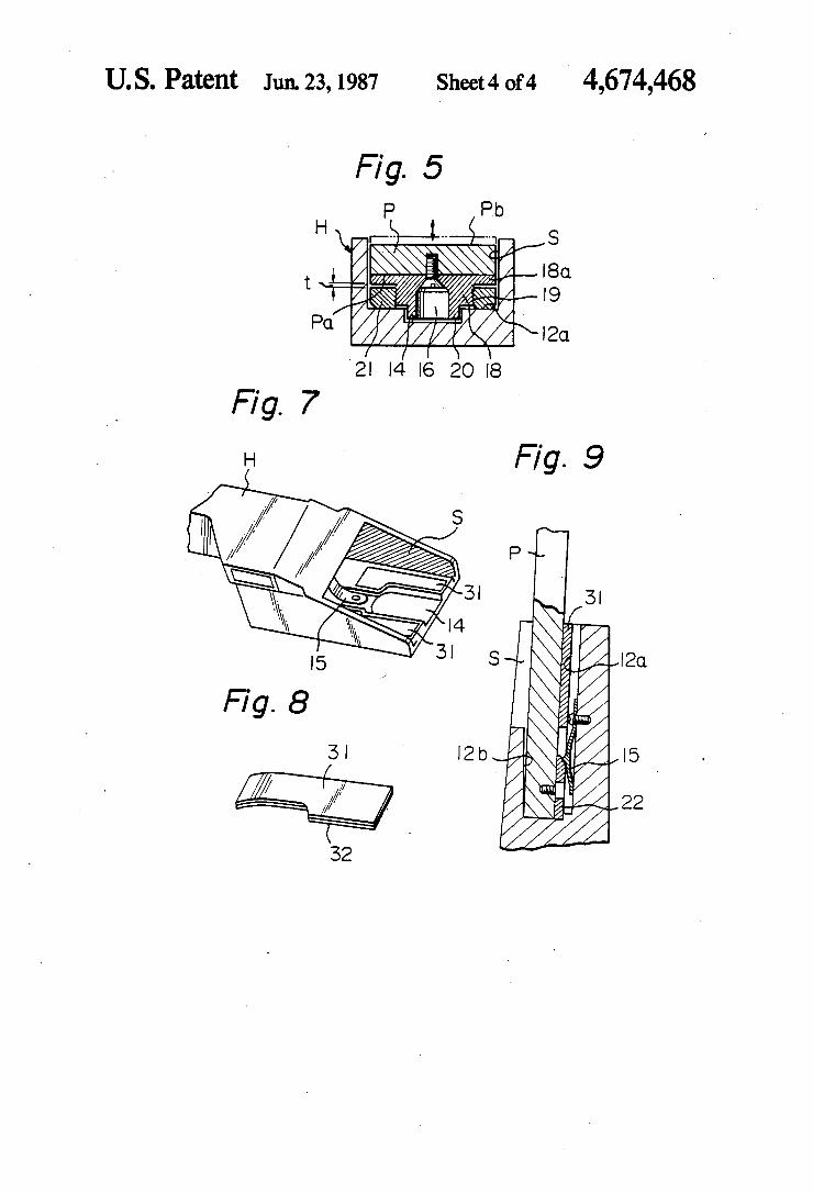
[57] ABSTRACT A joint structure between each limb and a handle riser of a take-down type archery bow is described employ ing a plug-socket engagement based upon a two posi tion support. The ?rst position support is located near the mouth of a handle riser socket and enables the change in angular position of the limbs with respect to the handle riser by the replacement of a pair of flat spacers of predetermined thickness. The second posi tion support, being unaffected by the ?rst position sup port, is located near the bottom of the socket for releas ably engaging the plug end of the limbs in order to prevent accidental removal of the limbs from the handle riser socket.
4 Claims, 9 Drawing Figures

U.S. Patent Mar.l1,1986 Sheetlof4 4,574,766

Patent Mar. 11, 1986 Sheet 2 of 4 4,574,766
Fig. 2 Fig. 3 ' PRIOR ART PRIOR ART

U.S. Patent Mar.1l,l986 Sheet30f4 4,574,766

US. Patent Manll, 1986 Sheet40f4 4,574,766
2| l4 I6 20 I8
I I. I.

United States Patent [19] Izuta
[54] JOINT STRUCTURE OF A TAKE-DOWN TYPE ARCHERY BOW
[75] Inventor:
[73] Assignee: Tadao Izuta, Hamamatsu, Japan
Nippon Gakki Seizo Kabushiki Kaisha, Japan
[21] Appl.No.: 801,001 [22] Filed: Nov. 22, 1985
Related US. Application Data
[62] Division of Ser. No. 404,291, Aug. 2, 1982, Pat. No. 4,574,766.
[30] Foreign Application Priority Data Aug. 6, 1981 [JP] Japan ......................... .. 56-ll7220[U]
[51] Int. Cl.4 ............... .. F41B 5/00 [52] US. Cl. ............................... .. 124/23 R; 124/ 88 [58] Field of Search .......... .. 124/23 R, 24 R, DIG. l,
124/88
[56] References Cited U.S. PATENT DOCUMENTS
3,874,360 4/1975 Armstrong et a1. ............. .. 124/23 R
1
i
[11] Patent Number: 4,674,468 [45] Date of Patent: Jun. 23, 1987
3,921,598 11/1975 Helmick .......................... .. 124/24R
3,942,506 3/1976 Izuta ............................... .4 124/24R
Primary Examiner—Richard C. Pinkham Assistant Examiner—Benjamin Layno Attorney, Agent, or Firm—Lerner, David, Littenberg, Krumholz & Mentlik
[57] ABSTRACT In a joint structure between each limb and a handle riser of a knock-down type archery bow employing a plug socket engagement, a two position support is formed by a pair of separate supporter pieces ?xed to the face side of the socket, one supporter piece located closer to the socket mouth forming the ?rst support for enabling change in angular position of the limb with respect to the handle riser, and the other supporter piece located closer to the socket bottom forming the second support unmoved by any change in the ?rst support. The ab sence of holes in the socket walls assures a strong con struction without the increase in weight, and the adjust ment by the ?rst support causes no disturbance on the originally designed balance of force over the entire construction.
3 Claims, 9 Drawing Figures

4,674,468 U. S. Patent Jun. 23,1987 Sheetl of4
U. S. Patent Jun. 23,1987 Sheet2 of4 4,674,468
PRIOR ART PRIOR ART
- . 1% A
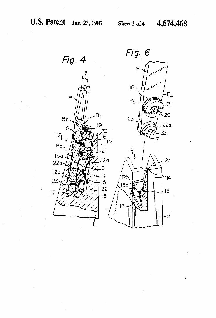
U. S. Patent Jun. 23,1987 Sheet3 of4 4,674,468
W .
U. S. Patent Jun. 23,1987 Sheet4 0f4 4,674,468

IllllllllllllllllIllllIlllllllllllllllllllIllllIlllllllllllllllllllllllllll US005172679A
United States Patent [19] [11] Patent Number: 5,172,679 Mussack [45] Date of Patent: Dec. 22, 1992
[54] MODULAR CONSTRUCTION FOR [56] References Cited COMPOUND ARCHERY BOW us. PATENT DOCUMENTS
75 I t l - ' - - 3,821,946 7/1974 [ ] nven or geggn R Mussack, Clifton Springs, 3184x195 10/1974 ' ' 3,942,506 3/1976
. 4,064,862 12/1977 [73] Asstgnee: Golden Eagle Archery, Inc., 4,261,320 4/1981
Farmington, NY. 4,574,766 3/1986
. Primary Examiner—Peter M. Cuomo [211 App]' No" 749’312 Attorney, Agent, or Fz'rm—Hoffrnan Stone
[22] Filed: Aug. 23, 1991 [57] ABSTRACT A modular construction for compound archery bows
R l d U s A l, _ includes sets of spacer blocks for insertion between the 6 ate ' ' pp ‘canon Data bow handle and the limbs. The blocks are shaped to
[63] Continuation-impart of Ser. No. 569,868, Aug. 20, provide selected variations in the geometry of the bows, 1990, abandoned. selectively adjusting the brace height and the overall
length of the bow. The manufacturer is enabled to cre [51] Int. Cl.5 .............................................. .. F41B 5/00 ate bOWs of many different characteristics without in [52] U.S. Cl. ................................ .. 124/25.6; 124/23.1; vesting in dies to produce differently shaped handles,
124/88 needing only differently shaped spacer blocks. [58] Field of Search ..................... .. 124/88, 25.6, 23.1, ‘
124/ 24.1, 86 3 Claims, 2 Drawing Sheets
14 22

US. Patent Dec.22,1992 Sheet 1 of 2 5,172,679
13
12
20
26+ 30
1O
16/
22 14
15 FIG. 1

US. Patent Dec. 22, 1992 Sheet 2 of 2 5,172,679
12
3 FIG.
FIG. 4'
llllllllllllllllllllllll|||llllllllllfllllllllllllllllllllllllllllllllllllll US005 6923A
Unlted States Patent [19] [11] Patent Number: 5 546 923 9 9
Duncan [45] Date of Patent: Aug. 20, 1996
[54] TAKE-DOWN ARCHERY BOW 3,942,506 3/1976 Izuta . 3,957,027 5/1976 Drake ...................................... .. 124/88
[76] Inventor: Douglas J. Duncan, 8157 Budworth 4,091,790 5/1973 Hoyt, Jr- - School Rd., PO. Box 742, Beetown, ill‘?
' , , zu a .
WIS‘ 53802 4,693,230 9/1987 Sugouchi ................................ .. 124/88
4,793,319 12/1988 Vaughan et a1.. [21] Appl. No.: 330,831 5,025,774 6/1991 Martin ..................................... .. 124/89
. 5,280,779 1/1994 Smith 124/88 [22] F1169: , Oct- 27’ 1994 5,291,874 3/1994 Harrison .............................. ..-. 124/23.1
6 ------------------------------------------------------ .
[52] US. Cl. . . . . . . . . . . . . . . . . . . . . . . . .. 124/23.1
[58] Field of Search ................................ .. 124/23.1, 24.1, Traditional BOW/hunter, NO- 76695, Aug/5994 1993, PP 124/25.6, 86, 88; 403/393 4647
[56] References Cited Primary Examiner—-Eric K. Nicholson Assistant Examiner—-J0hn A. Ricci
U.S. PATENT DOCUMENTS Attorney, Agent, or Firm-Arrnstrong, Westerman, Hatton', 261,610 7/1882 Howe. McLeland 8‘ Naughton
1,709,630 4/ 1929 Rounsevelle ......................... .. 124/231 2,125,591 8/1938 Smith. [57] ABSTRACT
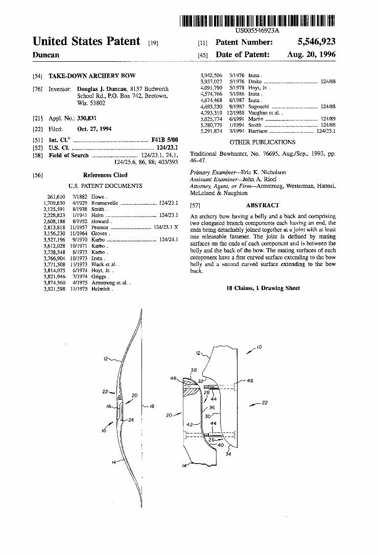
gelm .................................. .. 124/23.1 An archery bow having a belly and a back and comprising , , owar . -
2,813,818 11/1957 Pearson ............................ .. 1241231 X two elopgated branch .cqmponems each having a.“ and’ the 3 156 230 1m964 Groves ends being detachably JOlIlCd together at a]o1ntw1th at least 3,527,196 9/1970 Kal'bO ................. . . 124/241 one releasable fastener- The joint is de?ned by mating 3:612:028 10/1971 Karbo _ """"""" ' ' ' surfaces on the ends of each component and is between the
3,733,343 6/1973 Karbo _ belly and the back of the bow. The mating surfaces of each 3,766,904 10/1973 Izuta . component have a ?rst curved surface extending to the bow 3,771,508 11/1973 Black et a1. . belly and a second curved surface extending to the bow 3,814,075 6/1974 Hoyt, Jr. . back. 3,821,946 7/1974 Griggs. 3,874,360 4/1975 Annstrong et a1. . 3,921,598 11/1975 Helmick . 18 Claims, 1 Drawing Sheet
22

US. Patent Aug. 20, 1996 5,546,923
FIG. 1 IO
/
46R ‘
:2
22
2o/
22*‘.
16-».- . \AIB
/ . ,0 FIG. 2

United States Patent [19] Cox et al.
US006019097A
6,019,097 Feb. 1, 2000
[11] Patent Number:
[45] Date of Patent:
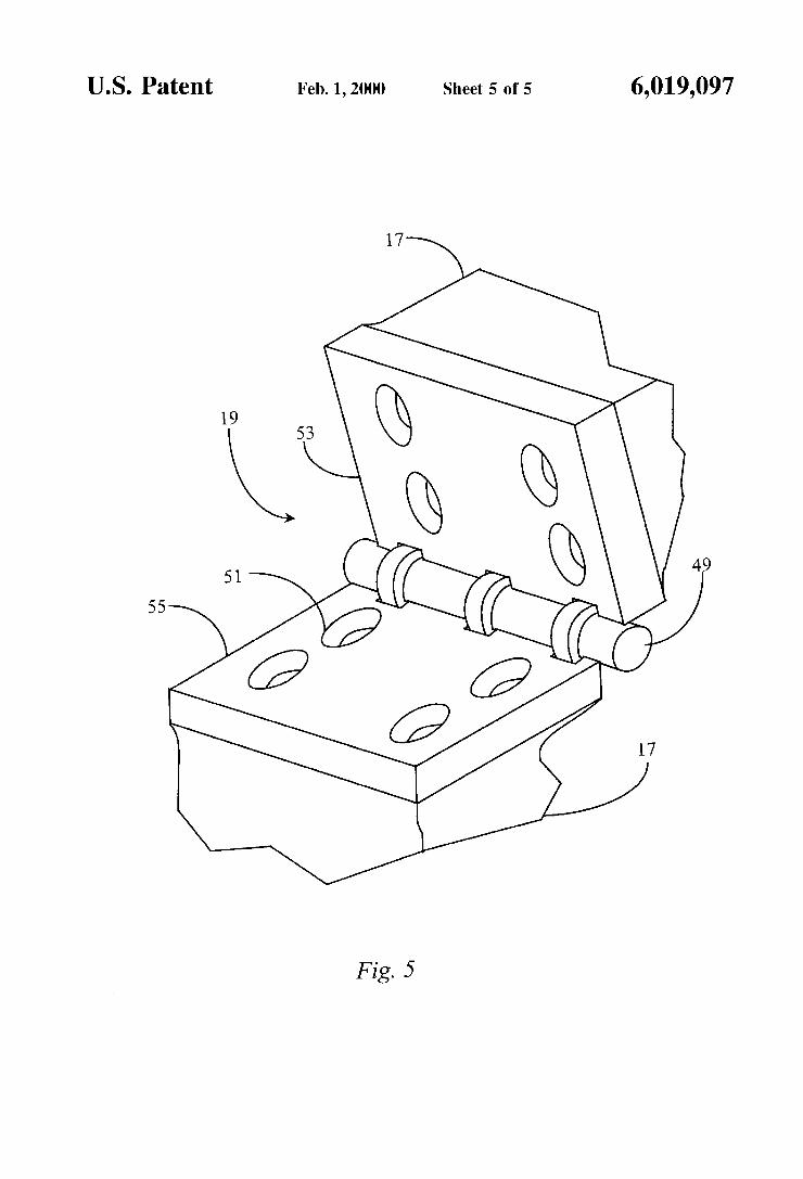
[54] DE-TENSIONING AND BREAKDOWN SYSTEM FOR A COMPOUND BOW
[76] Inventors: Jimmie D. Cox, 18701 Vierra Canyon Rd., Salinas, Calif. 93907; Douglas T. Bresette, 45 Rialto Dr., Watsonville, Calif. 95076
[21] Appl. N0.: 09/096,859
[22] Filed: Jun. 12, 1998
[51] Int. Cl.7 .. .............. .. F41B 5/00
[52] US. Cl. ................ .. . 124/23.1; 124/25.6
[58] Field of Search ............................ .. 124/1, 23.1, 25.6, 124/86, 88
[56] References Cited
U.S. PATENT DOCUMENTS
2,228,823 1/1941 Helm .................................... .. 124/231
2,514,638 7/1950 Grenier 124/231 3,156,230 11/1964 Groves . . . . . . . . . . . . . . . . . . .. 124/231
4,291,452 9/1981 Whitman et a1. .. 124/231 X 4,599,987 7/1986 ReZmer . . . . . . . . . . . . . . . . . .. 124/231
5,125,389 6/1992 Paff . . . . . . . . . . . .. 124/86
5,746,192 5/1998 Gissel ........................................ .. 124/1
Primary Examiner—John A. Ricci
ll
Attorney, Agent, or Firm—Milton Wolson
[57] ABSTRACT
A foldable archery bow has a center section and tWo ?exible arms extending in substantially opposite directions, describ ing a boW plane, and a separation interface disposed in the center section and positioned to alloW the boW to be sepa rated into to separate sections. At least one latching connec tor is attached to a ?rst point on one of the ?exible arms, and is adapted, When the ?exible arm to Which it is attached is substantially ?exed, to latch at a second point on the same side of the separation interface as the ?rst point. By drawing the boW, Which ?exes the ?exible arms, and latching the latching connector, all tension is released from the boW string or strings, and all forces thereby removed from the separation interface. The separation interface, normally fas tened in a closed position, may then be unfastened and separated, alloWing the boW to divide into the tWo separate sections forming a smaller package than in the assembled aspect. The boW may be again set up by aligning and refastening the separation interface, drawing the boW, and unlatching the connector, restoring the same tension to the how that it had before folding. In some embodiments a hinge is employed at the separation interface, alloWing the boW to fold, and a variety of force removal mechanisms are taught.
12 Claims, 5 Drawing Sheets

U.S. Patent Feb. 1,2000 Sheet 1 0f5 6,019,097
37 29
11

U.S. Patent Feb. 1,2000 Sheet 2 015 6,019,097
1 H
37 '
J 23
13 11 25
K / 24 -1, /
K / 17 36/38 _
/
19
41 —(0\/ K K 7/17 36/38 28
\ j 27
15 M 21
35


6,019,097 Sheet 4 0f 5 Feb. 1, 2000 U.S. Patent