
109
Goodwin, L., Schofield, D., Evison, M.P. and Lester, E. (2010). Effect of 3D rotation on
landmark visibility. In, Evison, M.P. and Vorder Bruegge, R.W. (Eds.) Computer-aided
forensic facial comparison. New York: Taylor and Francis, pp 89-100. ISBN
9781439811337
This text is the Accepted Manuscript only. The final volume can be found here.
Goodwin, L., Schofield, D., Evison, M.P. and Lester, E. (2010). Effect of 3D rotation on landmark visibility. In, Evison, M.P. and Vorder Bruegge, R.W. (Eds.) Computer-aided forensic facial comparison. New York: Taylor and Francis, pp 89-100. ISBN 9781439811337
110
CHAPTER 6
EFFECT OF 3D ROTATION ON LANDMARK VISIBILITY
Lorna Goodwin, Damian Schofield, Martin Evison and Edward Lester
A. INTRODUCTION
To be useful in forensic facial comparison, anthropometric landmarks must be capable of
distinguishing between subject’s faces and offer sufficient repeatability in placement that
observer error does not approach that of variability due to face shape differences.
A set of 62 3D anthropometric landmarks were ranked according to their repeatability, observer
error and power to distinguish between subject’s faces in Chapter 3. Landmark variation and
observer error in 2D images of subjects’ faces were described in Chapter 5. However, it is also
necessary to address the issue of landmark visibility under different viewing conditions.
Images encountered in forensic facial comparison arise from a variety of sources and the camera
angle is often not chosen for the benefit of identification. This Chapter is not an attempt to
measure landmark visibility from these diverse sources; rather, it is a general investigation of
landmark visibility in 3D, which provides potential guidelines for camera positioning for the
purposes of identification.
B. METHOD OF ANALYSIS
Goodwin, L., Schofield, D., Evison, M.P. and Lester, E. (2010). Effect of 3D rotation on landmark visibility. In, Evison, M.P. and Vorder Bruegge, R.W. (Eds.) Computer-aided forensic facial comparison. New York: Taylor and Francis, pp 89-100. ISBN 9781439811337
111
Three subjects were scanned using the Cyberware® 3030PS Head and Neck Scanner, which
unlike the Geometrix FaceVision® System, captures the full surface of the head, including the
ears. The 3D head geometry for each scanned subject was imported into 3ds MAX® modeling
software (Autodesk®, San Rafael, CA) using a 3ds file format.
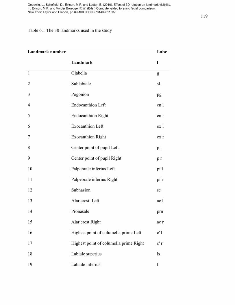
A set of 30 landmarks was chosen for analysis (Table 6.1). These landmarks are the optimal set
identified in Chapter 3, without substitution of the alares (al l and al r) for the alar crests (ac l and
ac r). The landmarks were manually located and marked, using tools within the modeling
software, on the 3D head geometry. Following the work of Aung et al. 1995, the nasal landmarks
were located in columella view; with the head tilted back about 30°.
After the remaining landmarks had been placed, the head was orientated into consistent planes in
each axis. The 3D head geometry was manually aligned into a consistent plane in 3ds MAX®.
Using the midline landmarks, the facial midline was orientated vertically in the coronal (x-y)
plane from the front viewport window and in the transverse (x-z) plane from the lateral viewport
window. The pronasale (prn) was not used, as this was observed to move off the midline in many
individuals.
In the front viewport, the position of the endocanthions (en l and en r) and exocanthions (ex l and
ex r) can be used for guidance as a line through these points (an inter-orbital line) will be at
approximately 90° to the midline. These landmarks, and the superaurales (sa l and sa r) and
subaurales (sba l and sba r), can also be used in the lateral view to provide similar guidance. The
Goodwin, L., Schofield, D., Evison, M.P. and Lester, E. (2010). Effect of 3D rotation on landmark visibility. In, Evison, M.P. and Vorder Bruegge, R.W. (Eds.) Computer-aided forensic facial comparison. New York: Taylor and Francis, pp 89-100. ISBN 9781439811337
112
position of these landmarks can not be expected to correspond perfectly with the midline as the
head is not a symmetric geometric form.
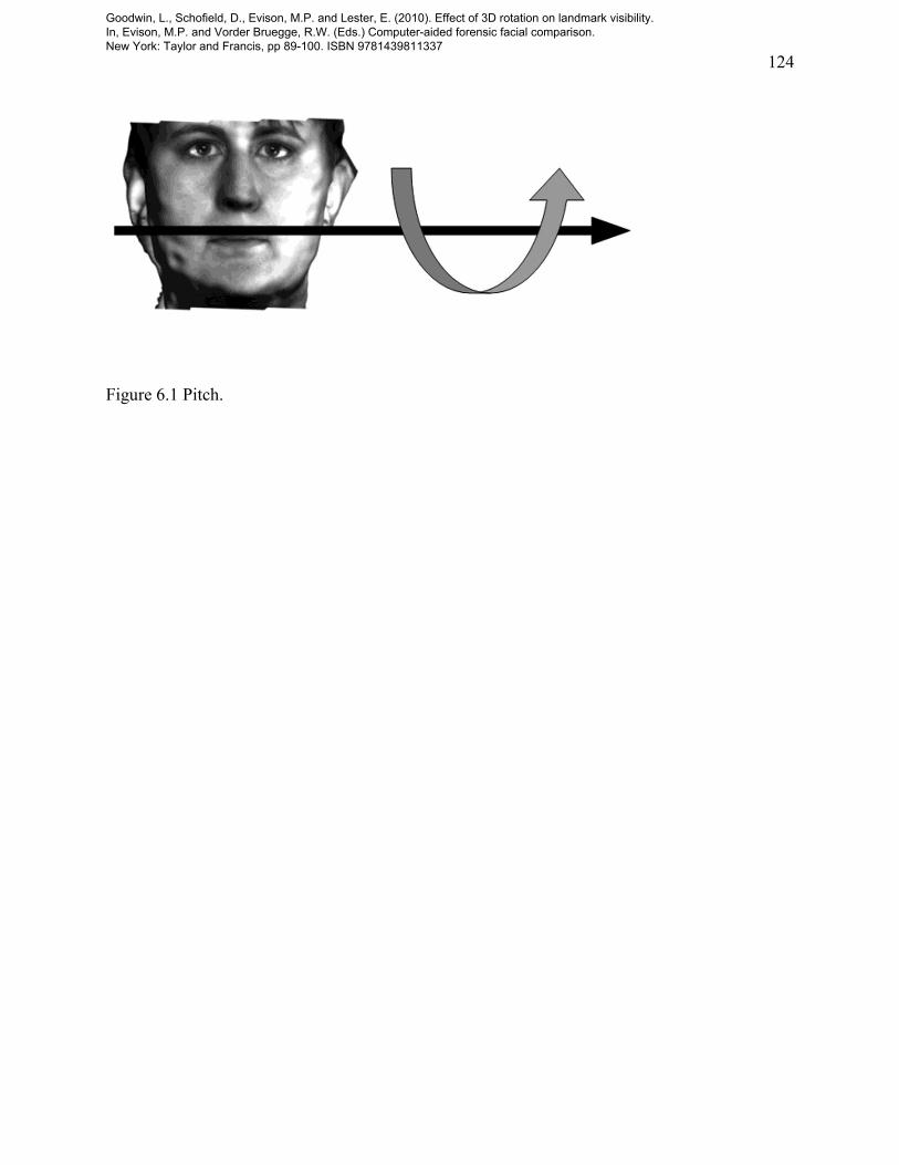
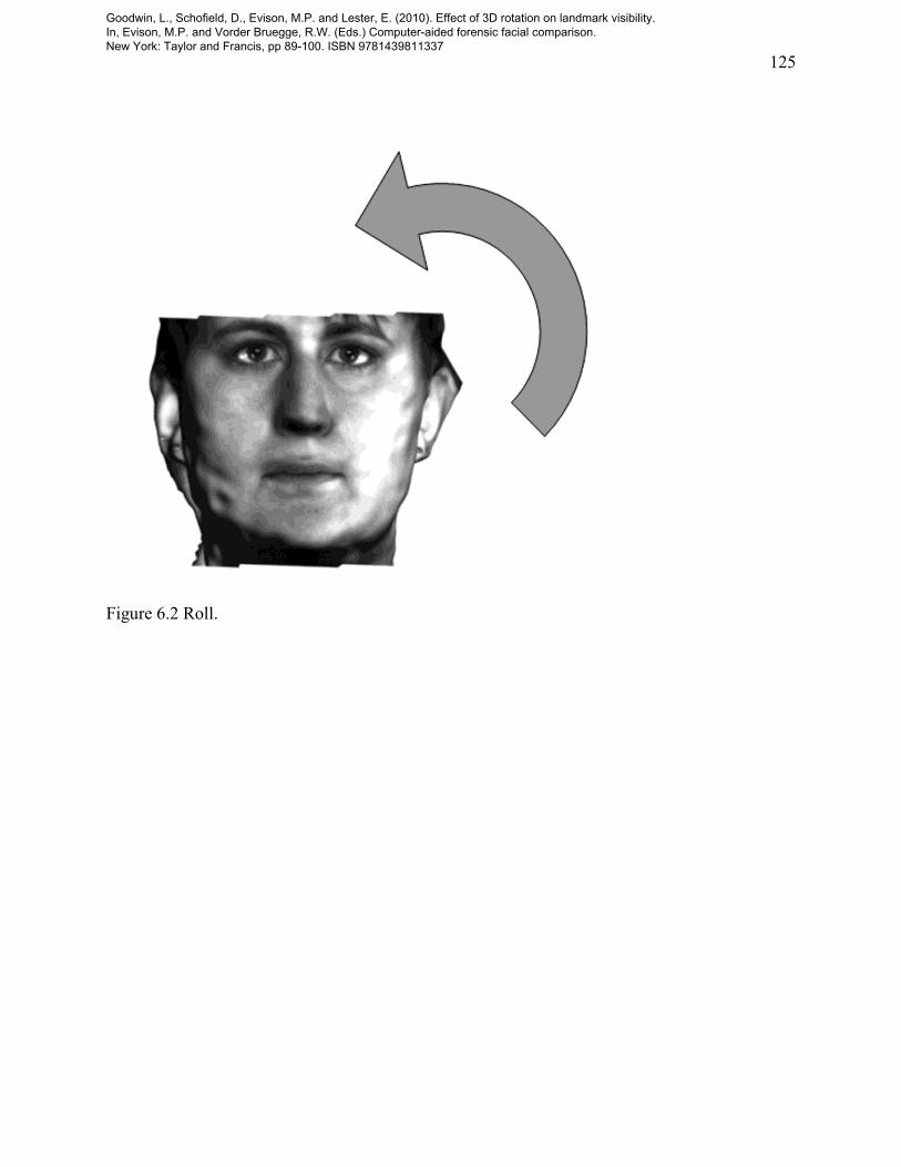
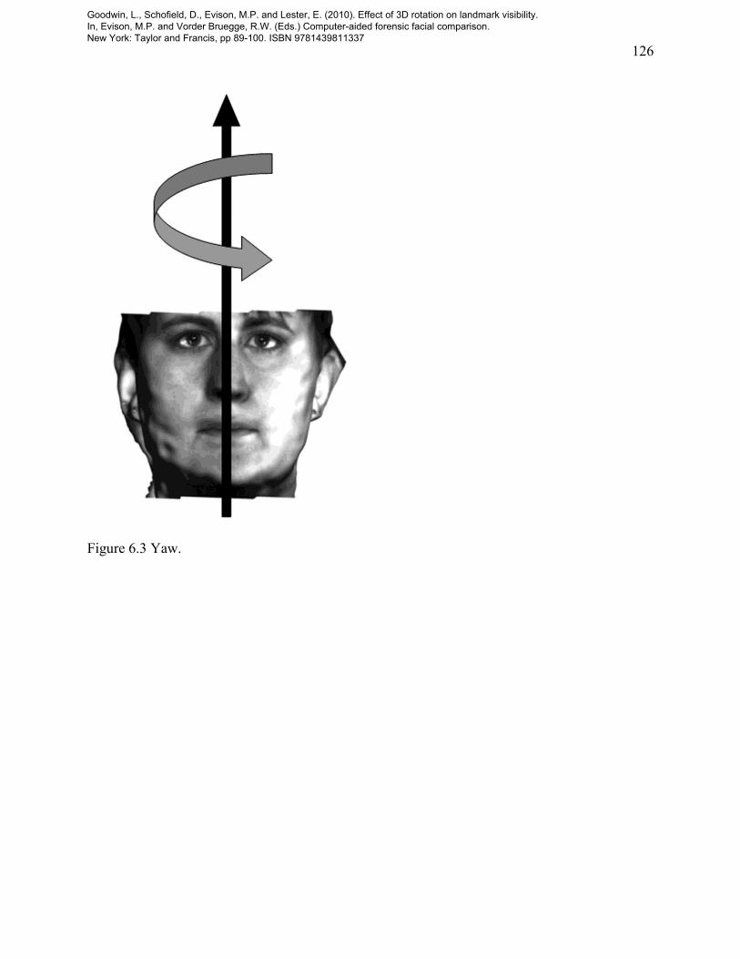
Landmark visibility was assessed in relation to the three axes of head rotation: pitch, roll and
yaw (see Figures 6.1 to 6.3). Pitch (Figure 6.1) describes rotation around the x axis. Roll (Figure
6.2) describes rotation around the y axis. Yaw (Figure 6.3) describes rotation around the z axis.
FIGURE 6.1 HERE
FIGURE 6.2 HERE
FIGURE 6.3 HERE
With the 3D geometry of each head consistently orientated into a starting position, it is now
necessary to locate a consistent pivot point (this is often also described as the camera target or
focal point) through which geometry might be rotated around the x, y and z axes. There is no
precise anatomical pivot point. An approximation that can be used as a point about which the
living head rotates is a point at the intersection of the mid-sagittal section and a line from the
otobasion inferius left (obi l) and otobasion inferius right (obi r) landmark points.
Although it is possible to rotate the 3D head geometry through 360o each of the three axes (if
increments of 1° were used), this would result in an impractical 3603 or 46,656,000 possible
Goodwin, L., Schofield, D., Evison, M.P. and Lester, E. (2010). Effect of 3D rotation on landmark visibility. In, Evison, M.P. and Vorder Bruegge, R.W. (Eds.) Computer-aided forensic facial comparison. New York: Taylor and Francis, pp 89-100. ISBN 9781439811337
113
orientations. For pragmatic reasons, therefore, 10° increments in orientation were chosen for
measurement.
Consideration of the influence of pitch, roll and yaw on landmark position and visibility
indicates that pitch and yaw are likely to have significant influence, but that the influence of roll
(Figure 6.2) is limited—in anterior view and in other combinations of pitch and roll. For this
reason, roll was also excluded from the analysis. Finally, few if any landmarks are visible from
the rear views of the head and it might be anticipated that practically, such views would not be
used in forensic facial comparison. Therefore, ranges of pitch and roll of between -900 to +90
0
pitch and -900 to +90
0 yaw, from the start position, were chosen for use in the analysis.
Automation of reorientation of 3D head geometry between -900 to +90
0 pitch and -90
0 to +90
0
yaw, in 10° increments, was achieved using software developed within the 3ds MAX® modeling
package, using the internal programming language, MAXScript®. In addition to automatic
reorientation of the geometry, MAXScript® was also used to render the reoriented images as
frame views, and to recognize and assess the RGB values and identify the position of any pixel
rendered in the frame.
In order to allow any pixel representing an anthropometric landmark to be distinguished, a
uniform RGB value was used to render the head geometry and scene background, and 30 other
distinct RGB values were used to render the 30 landmarks. In any orientation, therefore, the
presence or absence (visibility) of any landmark can be automatically detected by the software.
Goodwin, L., Schofield, D., Evison, M.P. and Lester, E. (2010). Effect of 3D rotation on landmark visibility. In, Evison, M.P. and Vorder Bruegge, R.W. (Eds.) Computer-aided forensic facial comparison. New York: Taylor and Francis, pp 89-100. ISBN 9781439811337
114
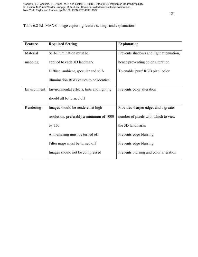
Although the 3ds MAX® modeling package offers a complex virtual reality modeling and
visualization environment, careful consideration of its parameters are essential to address
potential sources of error when using such a 3D modeling and rendering approach. A list of
modeling configuration parameters and rendering settings and the reason for these selections is
shown in Table 6.2.
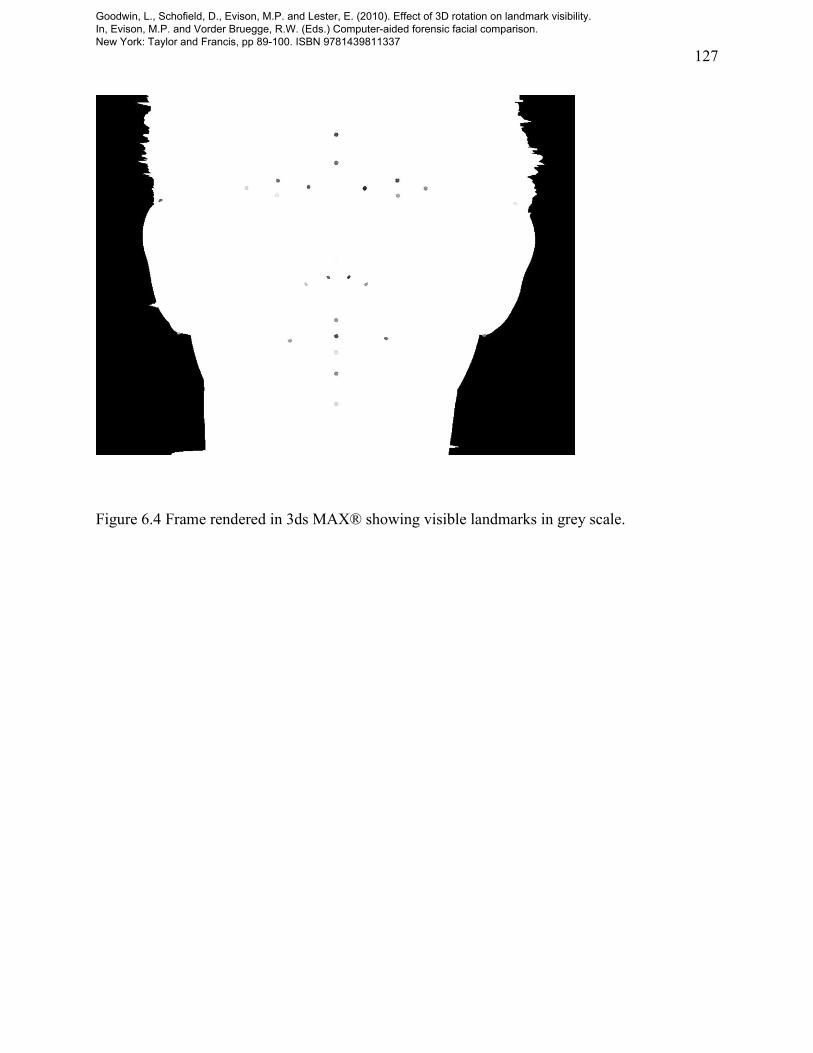
There are additional factors to be considered regarding compression of individual frames
rendered from 3ds MAX® using avi and mpeg codecs. Compression may distort pixel RGB
values being used to assess landmark visibility. For this reason, for each of the three subjects
scanned, nineteen avi files were generated, one for each 10° increment of pitch, each containing
nineteen uncompressed frames, one for each 10° increment of yaw, from which the landmark
visibility values could be derived (see Figure 6.4).
FIGURE 6.4 HERE
C. RESULTS OF LANDMARK VISIBILITY ANALYSIS
In order to allow convenient visualization of landmark visibility, the results for each landmark
were collated to Microsoft® Office 2003 Excel. A Visual Basic program was written to format
the data into a spreadsheet of nineteen pitch and nineteen yaw values, with landmark visibility
shown as a color value representing true or false in each cell of the spreadsheet. A number of the
90 Microsoft® Office 2003 Excel plots produced to show each landmark visibility spreadsheet
for each subject are shown, for illustration, in Figures 6.5 to 6.12.
Goodwin, L., Schofield, D., Evison, M.P. and Lester, E. (2010). Effect of 3D rotation on landmark visibility. In, Evison, M.P. and Vorder Bruegge, R.W. (Eds.) Computer-aided forensic facial comparison. New York: Taylor and Francis, pp 89-100. ISBN 9781439811337

115
FIGURE 6.5 HERE
FIGURE 6.6 HERE
FIGURE 6.7 HERE
FIGURE 6.8 HERE
FIGURE 6.9 HERE
FIGURE 6.10 HERE
FIGURE 6.11 HERE
FIGURE 6.12 HERE
Table 6.3 shows the ranking of landmarks by visibility calculated as the number of frames in
which the landmark is visible (out of a possible 361). The ranking in power to distinguish
between subject’s faces (see Chapter 3) is also shown.
D. SUMMARY
Goodwin, L., Schofield, D., Evison, M.P. and Lester, E. (2010). Effect of 3D rotation on landmark visibility. In, Evison, M.P. and Vorder Bruegge, R.W. (Eds.) Computer-aided forensic facial comparison. New York: Taylor and Francis, pp 89-100. ISBN 9781439811337

116
Landmark visibility follows a simple trend in which the prominence of facial features in any
given combination of pitch and yaw is the most influential factor. Landmarks tend to remain
visible until they become obscured by a more prominent feature than the one on which they are
located.
The eight most visible landmarks are all central to the face, located on or near the facial midline.
They tend not to be obscured by other facial features during pitch and yaw of the head. The
pronasale (prn) was the only landmark visible over the entire range of head orientations for all
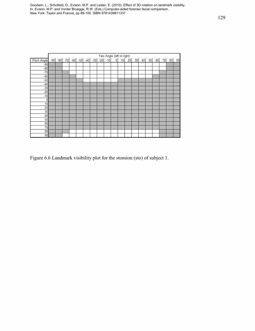
three subjects (see Figure 6.5). The stomion (sto) tends to be visible at the maximum range of
yaw, but becomes obscured, presumably by the upper and lower lip, when the head is pitched
down or up, respectively (see Figure 6.6).
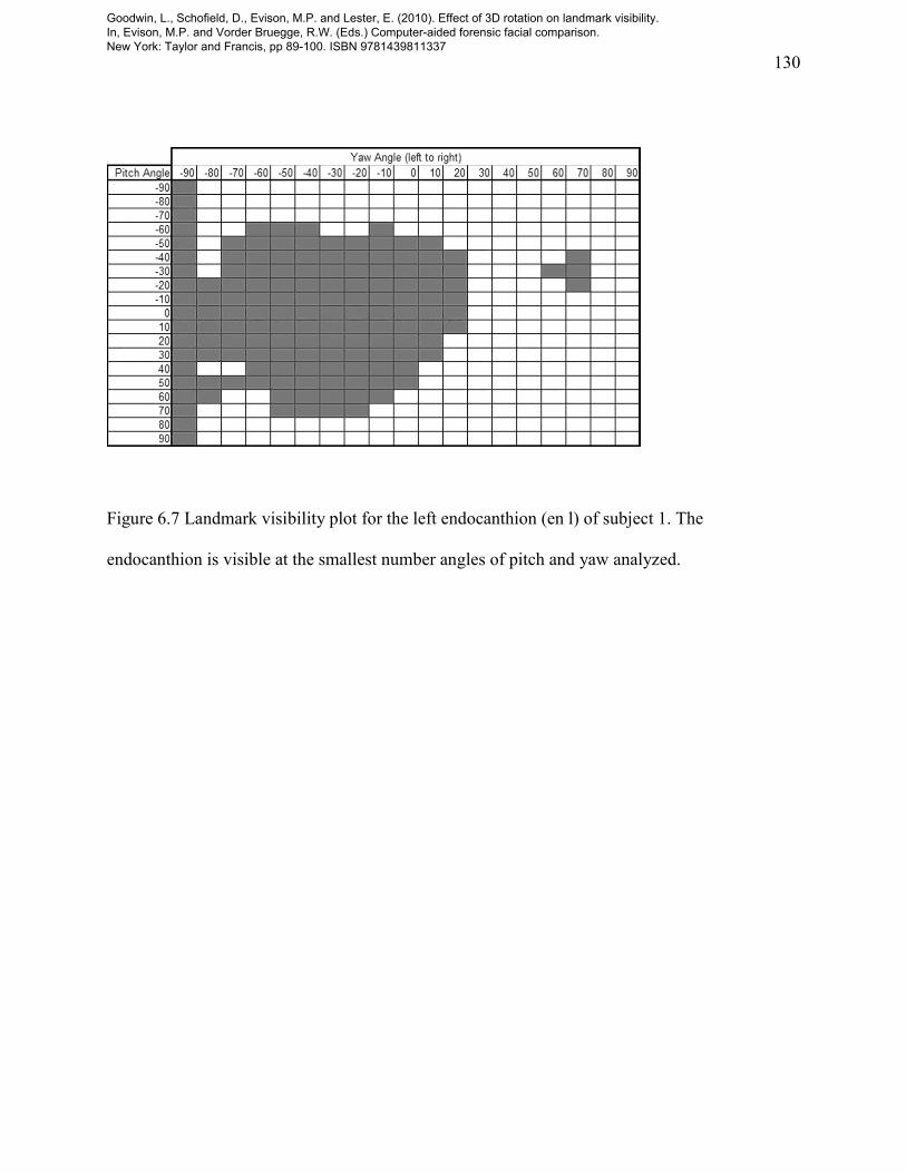
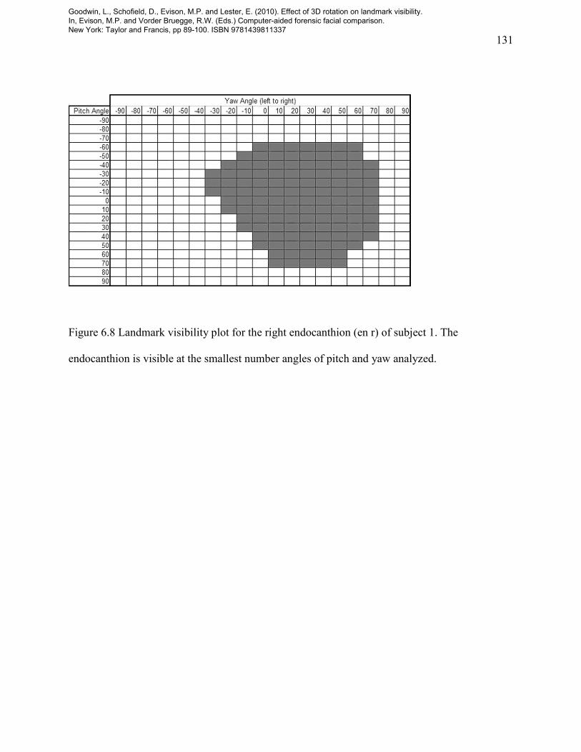
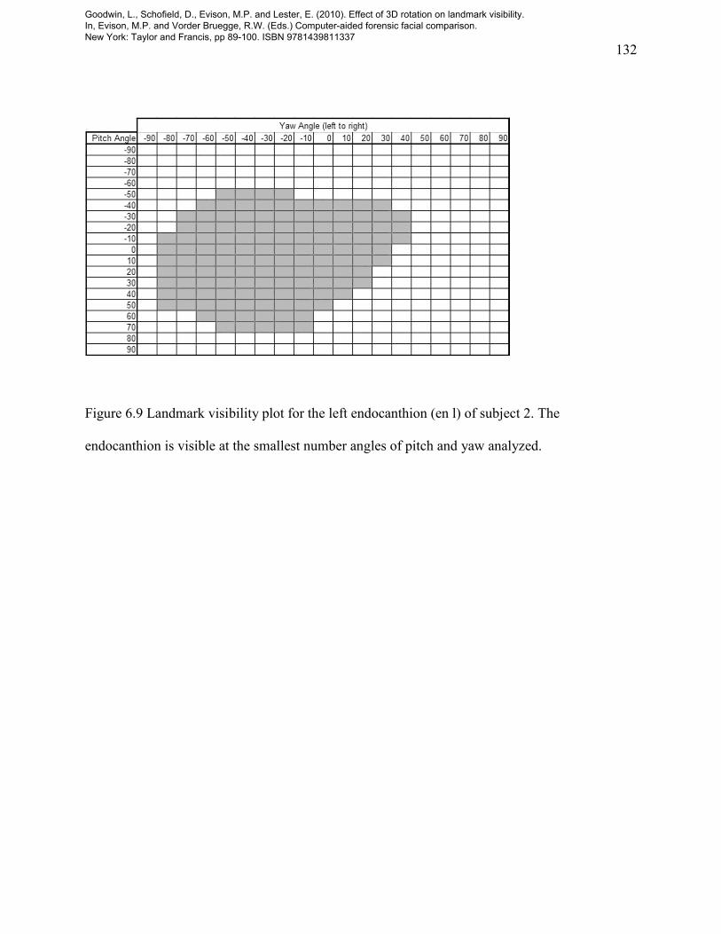
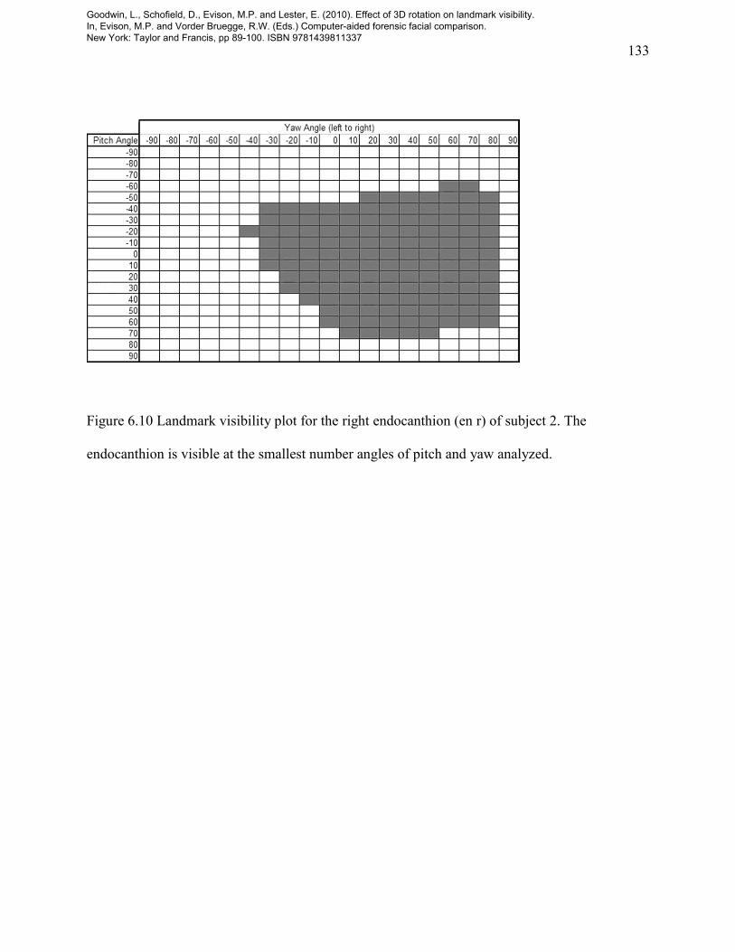
The endocanthions (en) have the least visibility for heads rotating between 90o pitch and yaw
(see Figures 6.7 to 6.10). They are easily hidden by surrounding facial features such as the nose
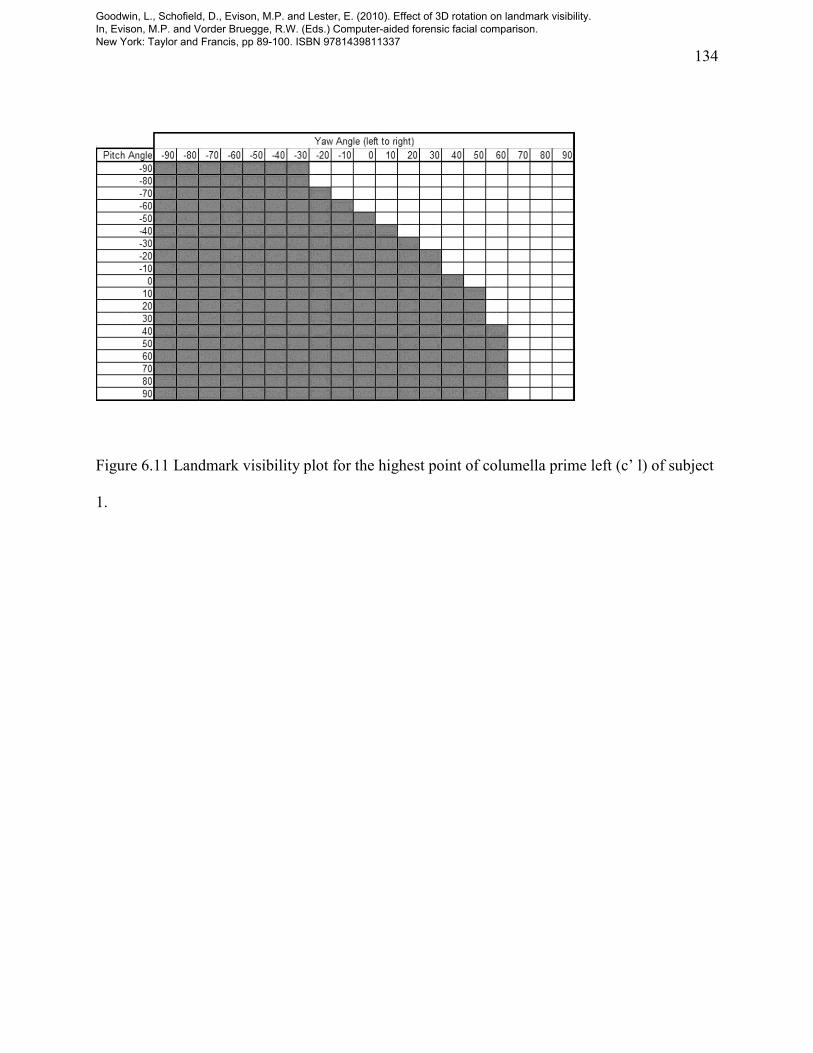
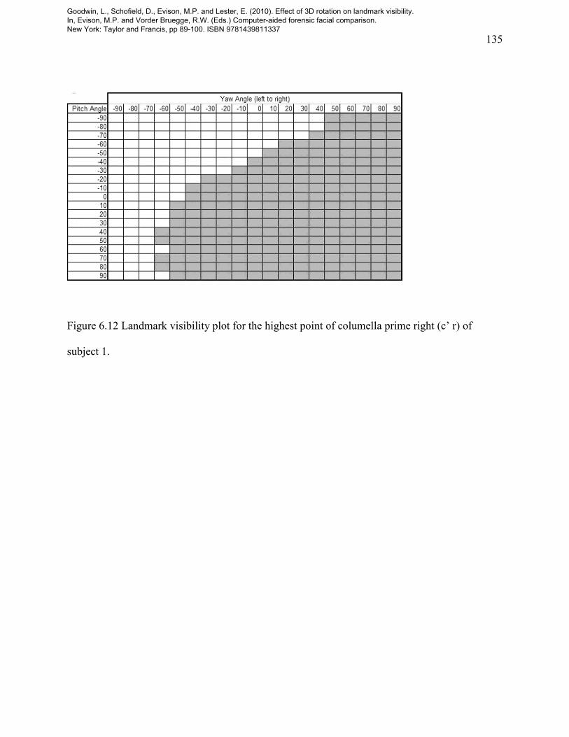
and bridge of the nose, the brow ridges and the protruding eyeballs. In contrast, the highest point
of columella prime (c’) landmarks are obscured by the nasal tip and alares in pitch and the
cheeks in yaw (see Figures 6.11 and 6.12).
The pronasale (prn) and other midline landmarks do not line up perfectly as the face is not
always symmetrical. Furthermore, there is often variation between individuals, as illustrated by
the comparison of the endocanthions (en) of subjects 1 and 2 (see Figures 6.7 to 6.10).
Goodwin, L., Schofield, D., Evison, M.P. and Lester, E. (2010). Effect of 3D rotation on landmark visibility. In, Evison, M.P. and Vorder Bruegge, R.W. (Eds.) Computer-aided forensic facial comparison. New York: Taylor and Francis, pp 89-100. ISBN 9781439811337

117
After the endocanthions (en), the next least visible landmarks are located on the ears, closely
followed by the cheilions (ch) on the corners of the mouth. As the ear landmarks are furthest
from the front of the face, they will be visible within limited ranges of yaw, and become quickly
obscured by hair, the ear itself and the other facial features. The cheilions (ch) are easily hidden
by the mouth, as they protrude from the face very little.
The remaining landmarks fall somewhere in between the pronasale (prn) and endocanthions (en),
depending on their position and potential to be obscured by other facial features during pitch and
yaw of the head, as reflected in their position in Table 6.3, according to the following factors:
The level of protrusion of the landmark: the distance between the landmark and the pivot
point.
The proximity, position, shape and relative size of other obscuring features
Two wider factors will inevitably have a major influence:
Variation in these factors from individual to individual
Camera position
Individual variation will influence landmark protrusion and the ability of other facial features to
obscure their visibility. In this investigation, the pronasale (prn) was chosen as the camera focal
point. The pattern of visibility would have been different if another focal point had been chosen.
Goodwin, L., Schofield, D., Evison, M.P. and Lester, E. (2010). Effect of 3D rotation on landmark visibility. In, Evison, M.P. and Vorder Bruegge, R.W. (Eds.) Computer-aided forensic facial comparison. New York: Taylor and Francis, pp 89-100. ISBN 9781439811337

118
There is no obvious relationship between landmark visibility and distinguishing power (see
Table 6.3). Further research, however, may permit the position of a camera or cameras to be
identified, which will yield optimum landmark visibility—or the best combination of visibility
and distinguishing power. The approach used in this investigation would readily lend itself to:
a complete analysis of 360° of pitch, role and yaw
an analysis with each landmark chosen as the focal point
analysis of a larger sample
Finally, there is the potential to ‘reverse engineer’ the approach used in this investigation to a
more general question relevant to forensic facial comparison: should these landmarks be visible
in this pose for this subject? If the answer is ‘no’, for example, an exclusion could possibly be
made.
E. REFERENCES
Aung, S.C., Ngim, R.C.K. and Lee, S.T. 1995. Evaluation of the laser scanner as a surface
measuring tool and its accuracy compared with direct facial anthropometric measurements.
British Journal of Plastic Surgery 48(8): 527–621.
Goodwin, L., Schofield, D., Evison, M.P. and Lester, E. (2010). Effect of 3D rotation on landmark visibility. In, Evison, M.P. and Vorder Bruegge, R.W. (Eds.) Computer-aided forensic facial comparison. New York: Taylor and Francis, pp 89-100. ISBN 9781439811337
119
Table 6.1 The 30 landmarks used in the study
Landmark number
Landmark
Labe
l
1 Glabella g
2 Sublabiale sl
3 Pogonion pg
4 Endocanthion Left en l
5 Endocanthion Right en r
6 Exocanthion Left ex l
7 Exocanthion Right ex r
8 Center point of pupil Left p l
9 Center point of pupil Right p r
10 Palpebrale inferius Left pi l
11 Palpebrale inferius Right pi r
12 Subnasion se
13 Alar crest Left ac l
14 Pronasale prn
15 Alar crest Right ac r
16 Highest point of columella prime Left c' l
17 Highest point of columella prime Right c' r
18 Labiale superius ls
19 Labiale inferius li
Goodwin, L., Schofield, D., Evison, M.P. and Lester, E. (2010). Effect of 3D rotation on landmark visibility. In, Evison, M.P. and Vorder Bruegge, R.W. (Eds.) Computer-aided forensic facial comparison. New York: Taylor and Francis, pp 89-100. ISBN 9781439811337
120
20 Stomion sto
21 Cheilion Left ch l
22 Cheilion Right ch r
23 Superaurale Left sa l
24 Superaurale Right sa r
25 Subaurale Left sba l
26 Subaurale Right sba r
27 Postaurale Left pa l
28 Postaurale Right pa r
29 Otobasion inferius Left obi l
30 Otobasion inferius Right obi r
Goodwin, L., Schofield, D., Evison, M.P. and Lester, E. (2010). Effect of 3D rotation on landmark visibility. In, Evison, M.P. and Vorder Bruegge, R.W. (Eds.) Computer-aided forensic facial comparison. New York: Taylor and Francis, pp 89-100. ISBN 9781439811337
121
Table 6.2 3ds MAX® image capturing feature settings and explanations
Feature Required Setting Explanation
Material
mapping
Self-illumination must be
applied to each 3D landmark
Prevents shadows and light attenuation,
hence preventing color alteration
Diffuse, ambient, specular and self-
illumination RGB values to be identical
To enable 'pure' RGB pixel color
Environment Environmental effects, tints and lighting
should all be turned off
Prevents color alteration
Rendering Images should be rendered at high
resolution, preferably a minimum of 1000
by 750
Provides sharper edges and a greater
number of pixels with which to view
the 3D landmarks
Anti-aliasing must be turned off Prevents edge blurring
Filter maps must be turned off Prevents edge blurring
Images should not be compressed Prevents blurring and color alteration
Goodwin, L., Schofield, D., Evison, M.P. and Lester, E. (2010). Effect of 3D rotation on landmark visibility. In, Evison, M.P. and Vorder Bruegge, R.W. (Eds.) Computer-aided forensic facial comparison. New York: Taylor and Francis, pp 89-100. ISBN 9781439811337

122
Table 6.3 Landmarks in order of visibility level with the ranking in power to distinguish between
faces (see Chapter 3) also shown.
Landmark
Number of frames visible Ranking in power to distinguish
between subjects’ faces Subject 1 Subject 2 Subject 3 Total
prn 361 361 361 1083 1
pg 356 356 353 1065 3
li 349 349 346 1044 22
ls 347 341 349 1037 33
g 316 355 355 1026 39
se 330 326 335 991 42
sl 280 320 326 926 11
sto 275 287 244 806 26
c’ r 234 256 260 750 18
c’ l 245 247 240 732 19
pi r 226 231 239 696 13
pi l 227 233 226 686 12
p r 217 220 232 669 10
p l 216 211 213 640 8
ex r 202 199 222 623 25
ex l 197 199 209 605 15
al r 192 216 195 603 55
al l 180 210 206 596 49
Goodwin, L., Schofield, D., Evison, M.P. and Lester, E. (2010). Effect of 3D rotation on landmark visibility. In, Evison, M.P. and Vorder Bruegge, R.W. (Eds.) Computer-aided forensic facial comparison. New York: Taylor and Francis, pp 89-100. ISBN 9781439811337

123
ch l 136 228 214 578 17
ch r 138 209 219 566 20
sba r 188 177 196 561 7
obi r 184 180 192 556 16
sba l 173 185 184 542 4
obi l 176 178 187 541 21
sa r 160 165 169 494 9
pa r 185 156 136 477 5
pa l 175 169 108 452 2
sa l 143 147 159 449 6
en l 145 127 119 391 28
en r 121 137 131 389 27
Goodwin, L., Schofield, D., Evison, M.P. and Lester, E. (2010). Effect of 3D rotation on landmark visibility. In, Evison, M.P. and Vorder Bruegge, R.W. (Eds.) Computer-aided forensic facial comparison. New York: Taylor and Francis, pp 89-100. ISBN 9781439811337
124
Figure 6.1 Pitch.
Goodwin, L., Schofield, D., Evison, M.P. and Lester, E. (2010). Effect of 3D rotation on landmark visibility. In, Evison, M.P. and Vorder Bruegge, R.W. (Eds.) Computer-aided forensic facial comparison. New York: Taylor and Francis, pp 89-100. ISBN 9781439811337
125
Figure 6.2 Roll.
Goodwin, L., Schofield, D., Evison, M.P. and Lester, E. (2010). Effect of 3D rotation on landmark visibility. In, Evison, M.P. and Vorder Bruegge, R.W. (Eds.) Computer-aided forensic facial comparison. New York: Taylor and Francis, pp 89-100. ISBN 9781439811337
126
Figure 6.3 Yaw.
Goodwin, L., Schofield, D., Evison, M.P. and Lester, E. (2010). Effect of 3D rotation on landmark visibility. In, Evison, M.P. and Vorder Bruegge, R.W. (Eds.) Computer-aided forensic facial comparison. New York: Taylor and Francis, pp 89-100. ISBN 9781439811337
127
Figure 6.4 Frame rendered in 3ds MAX® showing visible landmarks in grey scale.
Goodwin, L., Schofield, D., Evison, M.P. and Lester, E. (2010). Effect of 3D rotation on landmark visibility. In, Evison, M.P. and Vorder Bruegge, R.W. (Eds.) Computer-aided forensic facial comparison. New York: Taylor and Francis, pp 89-100. ISBN 9781439811337

128
Figure 6.5 Landmark visibility plot for the pronasale (prn) of subject 1. The landmark is visible
at all angles of pitch and yaw analyzed.
Goodwin, L., Schofield, D., Evison, M.P. and Lester, E. (2010). Effect of 3D rotation on landmark visibility. In, Evison, M.P. and Vorder Bruegge, R.W. (Eds.) Computer-aided forensic facial comparison. New York: Taylor and Francis, pp 89-100. ISBN 9781439811337
129
Figure 6.6 Landmark visibility plot for the stomion (sto) of subject 1.
Goodwin, L., Schofield, D., Evison, M.P. and Lester, E. (2010). Effect of 3D rotation on landmark visibility. In, Evison, M.P. and Vorder Bruegge, R.W. (Eds.) Computer-aided forensic facial comparison. New York: Taylor and Francis, pp 89-100. ISBN 9781439811337
130
Figure 6.7 Landmark visibility plot for the left endocanthion (en l) of subject 1. The
endocanthion is visible at the smallest number angles of pitch and yaw analyzed.
Goodwin, L., Schofield, D., Evison, M.P. and Lester, E. (2010). Effect of 3D rotation on landmark visibility. In, Evison, M.P. and Vorder Bruegge, R.W. (Eds.) Computer-aided forensic facial comparison. New York: Taylor and Francis, pp 89-100. ISBN 9781439811337
131
Figure 6.8 Landmark visibility plot for the right endocanthion (en r) of subject 1. The
endocanthion is visible at the smallest number angles of pitch and yaw analyzed.
Goodwin, L., Schofield, D., Evison, M.P. and Lester, E. (2010). Effect of 3D rotation on landmark visibility. In, Evison, M.P. and Vorder Bruegge, R.W. (Eds.) Computer-aided forensic facial comparison. New York: Taylor and Francis, pp 89-100. ISBN 9781439811337
132
Figure 6.9 Landmark visibility plot for the left endocanthion (en l) of subject 2. The
endocanthion is visible at the smallest number angles of pitch and yaw analyzed.
Goodwin, L., Schofield, D., Evison, M.P. and Lester, E. (2010). Effect of 3D rotation on landmark visibility. In, Evison, M.P. and Vorder Bruegge, R.W. (Eds.) Computer-aided forensic facial comparison. New York: Taylor and Francis, pp 89-100. ISBN 9781439811337
133
Figure 6.10 Landmark visibility plot for the right endocanthion (en r) of subject 2. The
endocanthion is visible at the smallest number angles of pitch and yaw analyzed.
Goodwin, L., Schofield, D., Evison, M.P. and Lester, E. (2010). Effect of 3D rotation on landmark visibility. In, Evison, M.P. and Vorder Bruegge, R.W. (Eds.) Computer-aided forensic facial comparison. New York: Taylor and Francis, pp 89-100. ISBN 9781439811337
134
Figure 6.11 Landmark visibility plot for the highest point of columella prime left (c’ l) of subject
1.
Goodwin, L., Schofield, D., Evison, M.P. and Lester, E. (2010). Effect of 3D rotation on landmark visibility. In, Evison, M.P. and Vorder Bruegge, R.W. (Eds.) Computer-aided forensic facial comparison. New York: Taylor and Francis, pp 89-100. ISBN 9781439811337
135
Figure 6.12 Landmark visibility plot for the highest point of columella prime right (c’ r) of
subject 1.
Goodwin, L., Schofield, D., Evison, M.P. and Lester, E. (2010). Effect of 3D rotation on landmark visibility. In, Evison, M.P. and Vorder Bruegge, R.W. (Eds.) Computer-aided forensic facial comparison. New York: Taylor and Francis, pp 89-100. ISBN 9781439811337
Recommended


