Embed Size (px)
Citation preview

29/10/1435
1
Pump CavitationCavitation should be avoided due to erosion damage and noise.
Cavitation occurs when P < Pv
8/25/2014 1
Vapor pressure: is the absolute pressure at which a liquid will evaporate at certain temperature
8/25/2014 2

29/10/1435
2
CAVITATION
8/25/2014 3
Concept of CavitationDefinitions:Some say when a pump makes a rattling or knocking sound along withvibrations it is cavitatingvibrations, it is cavitating.
Some call it slippage as the pump discharge pressure slips and flowbecomes erratic.
When cavitating, the pump not only fails to serve its basic purpose ofpumping the liquid but also may experience internal damage, leakage from
8/25/2014 4
the seal and casing, bearing failure, etc.

29/10/1435
3
Meaning of the Term "Cavitation" in the Context of the Centrifugal Pump
Th ‘ i i ’ f h L i d hi hThe term ‘cavitation’ comes from the Latin word cavus, which means ahollow space or a cavity.
Webster’s Dictionary defines the word ‘cavitation’ as the rapid formation andcollapse of cavities in a flowing liquid in regions of very low pressure.
8/25/2014 5
Types Of Bubbles Formed In The Liquid
Vapor bubbles
Gas bubbles
8/25/2014 6

29/10/1435
4
Vapor BubblesVapor bubbles are formed due to the vaporization of a process liquid that isbeing pumped. The cavitation condition induced by formation and collapseof vapor bubbles is commonly referred to as Vaporous Cavitation.p y p
Gas BubblesGas bubbles are formed due to the presence of dissolved gases in the liquidthat is being pumped (generally air but may be any gas in the system). Thecavitation condition induced by the formation and collapse of gas bubbles iscommonly referred to as Gaseous Cavitation.
8/25/2014 7
Both types of bubbles are formed at a point inside the pump where the localstatic pressure is less than the vapor pressure of the liquid (vaporouscavitation) or saturation pressure of the gas (gaseous cavitation).
Vaporous Cavitation It is the most common form of cavitation found in process plants.
Generally it occurs due to insufficiency of the available NPSH or internalGenerally it occurs due to insufficiency of the available NPSH or internal
recirculation phenomenon. It generally manifests itself in the form of
reduced pump performance, excessive noise and vibrations and wear of
pump parts. The extent of the cavitation damage can range from a relatively
minor amount of pitting after years of service to catastrophic failure in a
relatively short period of time.
8/25/2014 8
relatively short period of time.

29/10/1435
5
Gaseous Cavitation Occurs when any gas (most commonly air) enters a centrifugal pump along
with liquid. A centrifugal pump can handle air in the range of ½ % bywith liquid. A centrifugal pump can handle air in the range of ½ % by
volume. If the amount of air is increased to 6%, the pump starts cavitating.
The cavitation condition is also referred to as Air binding. It seldom causes
damage to the impeller or casing. The main effect of gaseous cavitation is loss
of capacity.
8/25/2014 9
Mechanism of Cavitation
8/25/2014 10

29/10/1435
6
Step One Formation of bubbles inside the liquid
being pumped.The bubbles form inside the liquid when it vaporises i.e. phase changefrom liquid to vapor.
But how does vaporization of the liquid occur during a pumping operation?
Vaporization of any liquid inside a closed container can occur if either
8/25/2014 11
Vaporization of any liquid inside a closed container can occur if eitherpressure on the liquid surface decreases such that it becomes equal to or lessthan the liquid vapor pressure at the operating temperature, or thetemperature of the liquid rises, raising the vapor pressure such that itbecomes equal to or greater than the operating pressure at the liquid surface.
To understand vaporization, two important points to remember are:
The static pressure and not the total pressureThe static pressure and not the total pressure.
The terms pressure and head have different meanings and theyshould not be confused
So, the key concept is ‐ vapor bubbles form due to vaporization of the liquid
8/25/2014 12
being pumped when the local static pressure at any point inside the pumpbecomes equal to or less than the vapor pressure of the liquid at the pumpingtemperature.

29/10/1435
7
How does pressure reduction occur in a pump ?system
The reduction in local static pressure at any point inside the pump can occurunder two conditions:under two conditions:
The actual pressure drop in the external suction system is greater than thatconsidered during design. As a result, the pressure available at pump suctionis not sufficiently high enough to overcome the design pressure drop insidethe pump.
The actual pressure drop inside the pump is greater than that consideredduring the pump design.
8/25/2014 13
g p p g
Pressure reduction in the external suction system of the pump
8/25/2014 14

29/10/1435
8
Pressure reduction in the external suction system of the pump
8/25/2014 15
8/25/2014 16Dr.Ihab G.Adam
Eng.HishamMohammed Khamys

29/10/1435
9
Flow path of fluid inside the pumpThe internal suction system is comprised of the pump’s suction nozzle andimpeller. Figures 5 and 6 depict the internal parts in detail.
8/25/2014 17
In Figure 7, it can be seen that the passage from the suction flange (point 2) to the impeller suction zone (point 3) and to the impeller eye (point 4) acts like a venturi i.e. there is gradual reduction in the cross‐section area.
8/25/2014 18

29/10/1435
10
In the impeller, the point of minimum radius (eye) with reference to pump centerline is referred to as the “eye” of the impeller (Figure 8).
8/25/2014 19Dr.Ihab G.Adam
Eng.HishamMohammed Khamys
How pressure reduction occurs as the fluid flows inside the pump?
8/25/2014 20

29/10/1435
11
Step TwoGrowth of bubbles
Unless there is no change in the operating conditions, new bubblescontinue to form and old bubbles grow in size.continue to form and old bubbles grow in size.
The bubbles then get carried in the liquid as it flows from the impellereye to the impeller exit tip along the vane trailing edge.
Due to impeller rotating action, the bubbles attain very high velocity andeventually reach the regions of high pressure within the impeller wherethey start collapsing.
8/25/2014 21
The life cycle of a bubble has been estimated to be in the order of 0.003seconds.
Step ThreeCollapse of bubbles
As the vapor bubbles move along the impeller vanes, the pressure aroundthe bubbles begins to increase until a point is reached where the pressure onthe outside of the bubble is greater than the pressure inside the bubblethe outside of the bubble is greater than the pressure inside the bubble.
The bubble collapses.
The process is not an explosion but rather an implosion (inward bursting).
Hundreds of bubbles collapse at approximately the same point on eachimpeller vane.
Bubbles collapse non‐symmetrically such that the surrounding liquidh f ll h d f l d
8/25/2014 22Dr.Ihab G.Adam
Eng.HishamMohammed Khamys
p y y g qrushes to fill the void forming a liquid micro jet.
The micro jet subsequently ruptures the bubble with such force that ahammering action occurs.
Bubble collapse pressures greater than 1 GPa (145x106 psi) have beenreported. The highly localized hammering effect can pit the pump impeller.

29/10/1435
12
The pitting effect
8/25/2014 23
Formation and collapse of a bubble
8/25/2014 24

29/10/1435
13
Impeller Cavitation Regions
8/25/2014 25
General Symptoms of Cavitation and its Effects on Pump Performance and Pump
Partsloud noises vibrations and an unsteadily working pumploud noises, vibrations and an unsteadily working pump.
Fluctuations in flow and discharge pressure take place with a sudden anddrastic reduction in head rise and pump capacity.
Depending upon the size and quantum of the bubbles formed and theseverity of their collapse, the pump faces problems ranging from a partialloss in capacity and head to total failure in pumping along with irreparabledamages to the internal parts.
8/25/2014 26
It requires a lot of experience and thorough investigation of effects ofcavitation on pump parts to clearly identify the type and root causes ofcavitation.

29/10/1435
14
1-Reduction in capacity of the pump The formation of bubbles causes a volume increase decreasing the space availablefor the liquid and thus diminish pumping capacity.
For example, when water changes state from liquid to gas its volume increases byi l i If h b bbl bi h h f h i llapproximately 1,700 times. If the bubbles get big enough at the eye of the impeller,
the pump “chokes” i.e. loses all suction resulting in a total reduction in flow.
The unequal and uneven formation and collapse of bubbles causes fluctuations inthe flow and the pumping of liquid occurs in spurts.
This symptom is common to all types of cavitations.
8/25/2014 27
2-Decrease in the head developed Bubbles unlike liquid are compressible. The head developed diminishes drasticallybecause energy has to be expended to increase the velocity of the liquid used to fillup the cavities, as the bubbles collapse.
As mentioned earlier, The Hydraulic Standards Institute defines cavitation ascondition of 3 % drop in head developed across the pump. Like reduction incapacity, this symptom is also common to all types of cavitations.
Thus, the hydraulic effect of a cavitating pump is that the pump performancedrops off of its expected performance curve, referred to as break away, producing alower than expected head and flow.
8/25/2014 28
p

29/10/1435
15
8/25/2014 29
3-Abnormal sound and vibrations
It is movement of bubbles with very high velocities from low‐pressure area to ahigh‐pressure area and subsequent collapse that creates shockwaves producingabnormal sounds and vibrations It has been estimated that during collapse ofabnormal sounds and vibrations. It has been estimated that during collapse ofbubbles the pressures of the order of 10000 atm develops.
The sound of cavitation can be described as similar to small hard particles orgravel rapidly striking or bouncing off the interior parts of a pump or valve.Various terms like rattling, knocking, crackling are used to describe theabnormal sounds.
People can easily mistake cavitation for a bad bearing in a pump motor. Todistinguish between the noise due to a bad bearing or cavitation, operate the
h fl h d f ll b d fg g p
pump with no flow. The disappearance of noise will be an indication ofcavitation.
8/25/2014 30

29/10/1435
16
Damage to pump partsCavitation erosion or pitting
8/25/2014 31
Cavitation Damage on Impellers
8/25/2014 32

29/10/1435
17
The two pictures are of the same area of a centrifugal pump impeller.
The one on the left shows a typical cavitation pattern during flow.
Bubbles are forming to the left and imploding at the impeller’s surface in the upperrightright.
The picture on the right shows the actual damage caused by continuous implosion ofbubbles in the same area.
8/25/2014 33
The picture shows damage at the low pressure side of the leading edge of an
impeller vane due to suction cavitation.
8/25/2014 34

29/10/1435
18
Net Positive Suction Head(NPSH)
What is Net Positive Suction Head??
Net Positive Suction Head. NPSH is what the pump needs, the minimumrequirement to perform its duties.
Therefore, NPSH is what happens in the suction side of the pump, including whatgoes on in the eye of the impeller.
NPSH takes into consideration the suction piping and connections, the elevationand absolute pressure of the fluid in the suction piping, the velocity of the fluid and
8/25/2014 35
the temperature.
Net positive Suction Head(NPSH)
Net positive Suction Head Available(NPSHA)
Net positive Suction Head Required(NPSHR)
8/25/2014 36
(NPSHA) (NPSHR)

29/10/1435
19
8/25/2014 37
8/25/2014 38

29/10/1435
20
Net positive Suction Head Available (NPSHA)
The difference between the total suction head and theThe difference between the total suction head and thevapor pressure of the liquid at the suction flange.
Calculating NPSHA of a piping system
NPSHA = hsa – hvpa
where:hsa Total suction head absolute
8/25/2014 39
hsa = Total suction head, absolutehvpa = Vapor pressure of liquid at the pumping temperature, absolute.
hsa = hpsa + hss – hfs
where:hpsa = suction surface pressure, absolute, on the surface of the liquid from which
the pump takes its suction. This will be the atmospheric pressure, in the caseof an open tank, or the absolute pressure above the liquid in a closed tank.p p q
hss = static suction head. In other words, the height of the liquid surface in thesuction tank above or below the pump centerline. (Positive if the liquid levelis above the pump, negative if the liquid level is below the pump).
hfs = friction head loss, between the liquid surface in the suction tank and thesuction flange of the pump.
8/25/2014 40

29/10/1435
21
Net Positive Section Head and Cavitation (NPSH)
NPSH Available
Net Positive Suction Head (NPSH)
Suction supply open to atmosphere with section lift.
NPSHA =PB – (VP +LS +hf)
Where
PB= Barometric pressure in feet absolute.
V V f th li id t i
8/25/2014 41
VP= Vapor pressure of the liquid at maximumpumping temperature, in feet absolute.
Ls = Maximum static suction lift in feet.
hf = Friction loss in feet in suction pipe atrequired capacity.
Net Positive Section Head and Cavitation (NPSH)
NPSH Available
Net Positive Suction Head (NPSH)
Suction supply open to atmosphere with section head.
NPSHA =PB + LH ‐ (VP +hf)
Where
PB= Barometric pressure in feet absolute.
V V f th li id t i
8/25/2014 42
VP= Vapor pressure of the liquid at maximumpumping temperature, in feet absolute.
LH = Minimum static suction head in feet.
hf = Friction loss in feet in suction pipe atrequired capacity.

29/10/1435
22
Net Positive Section Head and Cavitation (NPSH)
NPSH Available
Net Positive Suction Head (NPSH)
Closed suction supply with suction head.
NPSHA =P + LH ‐ (VP +hf)
Where
P = Pressure on surface of liquid in closedsuction tank, in feet absolute.
8/25/2014 43
VP= Vapor pressure of the liquid at maximumpumping temperature, in feet absolute.
LH = Minimum static suction head in feet.
hf = Friction loss in feet in suction pipe atrequired capacity.
Net Positive Section Head and Cavitation (NPSH)
NPSH Available
Net Positive Suction Head (NPSH)
Closed suction supply with suction lift.
NPSHA = P ‐ (VP ‐ LS +hf)
Where
P = Pressure on surface of liquid in closedsuction tank, in feet absolute.
8/25/2014 44
VP= Vapor pressure of the liquid at maximumpumping temperature, in feet absolute.
hf = Friction loss in feet in suction pipe atrequired capacity.
Ls = Maximum static suction lift in feet.

29/10/1435
23
Net Positive Suction Head Required (NPSHR)
The reduction in total head as the liquid enters the The reduction in total head as the liquid enters the pump.
8/25/2014 45
8/25/2014 46

29/10/1435
24
8/25/2014 47
NPSH testingTwo procedures are used for NPSHR testing as follows:‐
Establishing a constant NPSHA and then varying the pump flow by means ofa discharge control valve until a predetermined amount of deteriorationa discharge control valve until a predetermined amount of deterioration(usually 3 percent) in the pump discharge head performance is observed
8/25/2014 48

29/10/1435
25
An alternate procedure is to hold capacity constant while the NPSH available isreduced by either throttling or changing the vacuum on the pump suction
8/25/2014 49
Methods of reducing NPSHA
1‐Valve suppression
In the valve suppression method of testing, a valve, located in thesuction line leading to the pump, is used to reduce the suction pressureby throttling, thus creating varying NPSHA conditions.
8/25/2014 50

29/10/1435
26
2‐Vacuum method
An alternate to valve suppression testing is to create a vacuum on the suctionside of the pump . This is done by using a tank or reservoir in which the pressureabove the liquid is reduced by means of an ejector or a vacuum pump.
8/25/2014 51
The objective of all these testing methods is to establish the NPSH requirements,at various flow rates, for a given impeller‐casing combination and to construct anNPSHr versus flow capacity curve.
8/25/2014 52

29/10/1435
27
Suction specific speedA dimensionless rating number which indicates the relative ability of centrifugalpumps to operate under conditions of low available net positive suction head.
where:S = suction specific speedN = rotative speed, in revolutions per minuteQ = capacity, at best efficiency, in gallons per minutehsv = net positive suction head required by maximum diameter impeller at bestefficiency, in feet
Depending on impeller design suction specific speeds will vary in numerical value
8/25/2014 53
Depending on impeller design, suction specific speeds will vary in numerical valuefrom below 4,000 to above 11,000 with the higher values indicating lower net positivesuction head requirements.
General rule to avoid cavitation
NPSHa > NPSHr + 3 ft or more safety margin
8/25/2014 54

29/10/1435
28
NPSH margin
According to the Hydraulic Institute, NPSH margin is required above the NPSHR f h h f f
Net Positive Suction Head (NPSH)
of the pump to suppress incipient cavitation. The amount of margin is a function of Suction Energy and the critical nature of the application as follows:
NPSHMargin Ratio (NPSHA/NPSHR)
Low 1.1 ‐ 1.3
High 1.2 ‐ 1.7
Very High 1.7 ‐ 2.5
8/25/2014 55
y g 7 5
Pump Cavitation and NPSH
Cavitation should be avoided due toerosion damage and noise.
Cavitation occurs when P < Pv
Net positive suction head
8/25/2014 56
NPSH required curves are createdthrough systematic testing over a rangeof flow rates V.

29/10/1435
29
If the pump operates to the right of point A then the required suction head
Net Positive Suction Head (NPSH)
Cavitation
point A, then the required suction head is greater than the available suction head. This means that vapour bubbles will occur in the suction pipe.
While Operation to the left of point A means that vapour bubbles will not form, and so Cavitations will not be a
bl
8/25/2014 57
problem.
If the available NPSH is not greater than that required by the pump, the following serious problems can result :‐
1. A marked reduction in head and capacity (the energy expended in acceleratingthe liquid to high velocity in filling the void left by the bubble is a loss, andq g y g y ,causes the drop in head, while the loss in capacity is the result of pumping amixture of vapor and liquid instead of liquid).
2. Excessive vibration can occur when sections of the impeller are handling vaporand the other sections handling liquid.
3. Probably the most serious problem is pitting and erosion of the pump parts,resulting in reduced life.
8/25/2014 58
4. Erratic flow rate with spurts of liquid being thrown from the discharge pipe.

29/10/1435
30
The solid line curves represent a condition of adequate NPSHa whereas the dotted lines depict the condition of inadequate NPSHa
i e the condition of cavitationi.e. the condition of cavitation.
8/25/2014 59
8/25/2014 60
Impeller damaged by cavitation

29/10/1435
31
8/25/2014 61
8/25/2014 62
29/10/1435
32
Detecting a low NPSHA problem
A centrifugal pump in the field that is cavitatingoften will sound as if it is pumping rocks andoften will sound as if it is pumping rocks, andfrequently the discharge pressure will pulsate. Asimple way to determine if the problem is a flow‐induced NPSH problem is to slowly shut down onthe discharge block valve. If the problem is flow‐induced, the noise and the pulsations should goaway as the flow is reduced through the pump
8/25/2014 63
away as the flow is reduced through the pump.
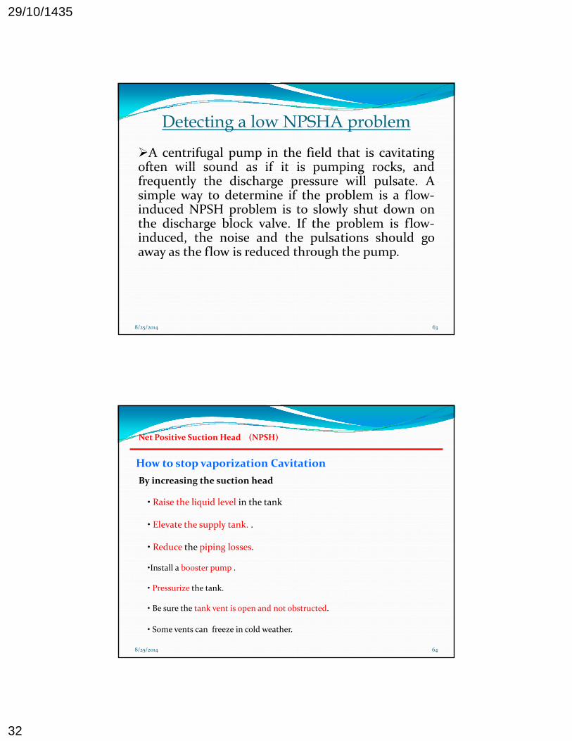
How to stop vaporization Cavitation
By increasing the suction head
Net Positive Suction Head (NPSH)
• Raise the liquid level in the tank
• Elevate the supply tank. .
• Reduce the piping losses.
•Install a booster pump .
• Pressurize the tank.
• Be sure the tank vent is open and not obstructed.
• Some vents can freeze in cold weather.
8/25/2014 64
29/10/1435
33
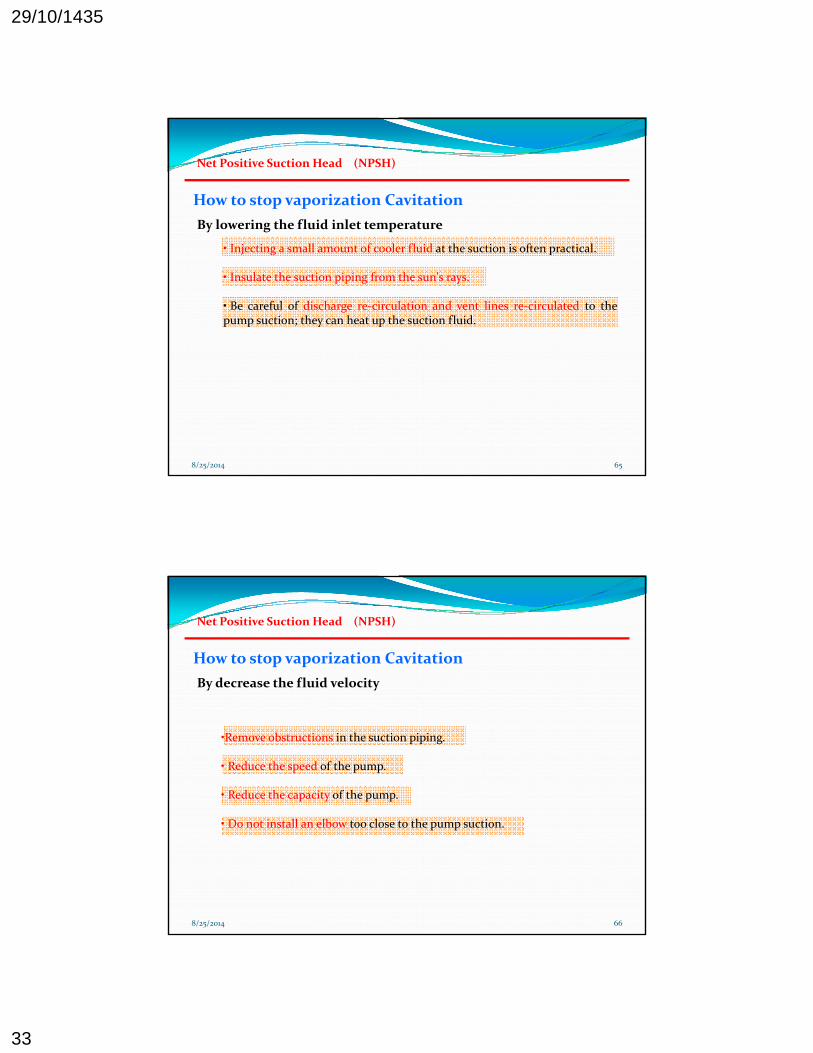
How to stop vaporization Cavitation
By lowering the fluid inlet temperature
Net Positive Suction Head (NPSH)
• Injecting a small amount of cooler fluid at the suction is often practical.
• Insulate the suction piping from the sun's rays.
• Be careful of discharge re‐circulation and vent lines re‐circulated to the pump suction; they can heat up the suction fluid.
8/25/2014 65
How to stop vaporization Cavitation
By decrease the fluid velocity
Net Positive Suction Head (NPSH)
•Remove obstructions in the suction piping.
• Reduce the speed of the pump.
• Reduce the capacity of the pump.
• Do not install an elbow too close to the pump suction.
8/25/2014 66

29/10/1435
34
How to stop vaporization Cavitation
By reducing the net positive suction head required (NPSHR)
Net Positive Suction Head (NPSH)
• Use a double suction pump. Double suction designs can reduce the net positive suction head required (NPSHR) by as much as 27%,
• Use a lower speed pump.
• Use a pump with a larger impeller eye opening.
• Use several smaller pumps. Three half‐capacity pumps can be cheaper than one large pump plus a spare. This will also conserve energy at lighter loads.
8/25/2014 67
8/25/2014 68Pump fitted with inducer

29/10/1435
35
Pump Priming* Why you must prime a centrifugal pump ? To remove air from the pump cavities and the suctionpiping the pump must develop enough head to equal thepiping, the pump must develop enough head to equal theequivalent of one bar pressure which extends from theearth’s atmosphere.
SinceSince thethe weightweight ofof waterwater isis approximatelyapproximately 80008000 timestimesthatthat ofof air,air, thethe centrifugalcentrifugal pumppump cancan produceproduce onlyonly 11//80008000 ofofitsits ratedrated liquidliquid pressurepressure..
anotheranother explanationexplanation::‐‐ AA centrifugalcentrifugal pumppump isis aa rotodynamicrotodynamic pumppump
69
AA centrifugalcentrifugal pumppump isis aa rotodynamicrotodynamic pumppump.. AsAs headhead == pressurepressure // spsp.. WeightWeight ofof thethe pumpedpumped liquidliquid.. thethe pressurepressure differencedifference createdcreated withwith airair willwill bebe onlyonly aroundaround 11//800800 timestimes thatthat withwith waterwater duedue toto thethe densitydensity differencedifference..
Priming Process
“ It is a process of air/vapor removal frompump suction andcasing by filling itup with liquid ”.
70
up with liquid .

29/10/1435
36
Positive displacement pumps primingPositive displacement pumps priming
WhenWhen pumpingpumping lowlow‐‐viscosityviscosity liquidsliquids ,, aa footfoot valvevalvep p gp p g yy qqmaymay bebe usedused toto helphelp keepkeep thethe pumppump primedprimed..Alternately,Alternately, aa vacuumvacuum devicedevice maymay bebe usedused toto primeprimethethe pumppump..
WhenWhen handlinghandling liquidsliquids ofof higherhigher viscosity,viscosity, footfoot
71
gg qq gg y,y,valvesvalves areare usuallyusually notnot requiredrequired becausebecause liquidliquid isisretainedretained inin thethe clearancesclearances andand actsacts asas aa sealseal whenwhenthethe pumppump isis restartedrestarted..
C.P Priming Methods Install a foot valve in the suction piping.
Evacuate the air in the system with a positive Evacuate the air in the system with a positivedisplacement priming pump.
Fill the pump with liquid prior to starting it using ahose or a small pot.
Make a bypass line from discharge line.
72
Make a bypass line from discharge line.
Convert the application to a self priming pump thatmaintains a reservoir of liquid at its suction.

29/10/1435
37
Priming Chambers
1‐ Single Chamber tank
73
2‐ Double Chamber Tank:
74

29/10/1435
38
Testing for Air in Centrifugal Pumps
The presence of only small quantities of air can result in The presence of only small quantities of air can result in id bl d i i i i l id bl d i i i i l % f i % f i considerable reduction in capacity, since only considerable reduction in capacity, since only 22% free air % free air
will cause a will cause a 1010% reduction in capacity, and % reduction in capacity, and 44% free air will % free air will reduce the capacity by reduce the capacity by 4343..55%. %.
Entrained air is one of the most frequent causes of shaft Entrained air is one of the most frequent causes of shaft breakage. It also may cause the pump to lose its prime and breakage. It also may cause the pump to lose its prime and greatly accelerate corrosion.greatly accelerate corrosion.
75
If air is present, the pump is likely to operate with a certain If air is present, the pump is likely to operate with a certain amount of internal noise. This noise can be described as a amount of internal noise. This noise can be described as a "gravel noise" "gravel noise"
We will assume that calculations We will assume that calculations have already been made to assure have already been made to assure that the NPSH available is greater that the NPSH available is greater than that required by the pump, than that required by the pump, (the noise is not a result of (the noise is not a result of cavitation). cavitation).
When the source of suction supply When the source of suction supply is above the centerline of the pump, is above the centerline of the pump, a check for air leaks can be made by a check for air leaks can be made by collecting a sample in a "bubble collecting a sample in a "bubble bottlebottle““..
Since the pressure at the suction Since the pressure at the suction chamber of the pump is above chamber of the pump is above atmospheric pressure, a valve can atmospheric pressure, a valve can
76
p p ,p p ,be installed in one of the tapped be installed in one of the tapped openings at the high point in the openings at the high point in the chamber and liquid can be fed into chamber and liquid can be fed into the "bubble bottle." The presence of the "bubble bottle." The presence of air or vapor will show itself in the air or vapor will show itself in the "bubble bottle.""bubble bottle."

29/10/1435
39
Self Priming Pumps
Self‐priming pumps overcomes the air bindingproblem by mixing air with water to create apumpable fluid with pumping properties muchpumpable fluid with pumping properties muchlike those of regular water .
recirculating water within the pump on primingcycle is the main operation concept.
This type of pump differs from a standardcentrifugal pump in that it has a ater reser oir
77
centrifugal pump in that it has a water reservoirbuilt into the unit may be above the impeller or infront of the impeller.
aa chargecharge ofof liquidliquid sufficientsufficient totoprimeprime thethe pumppump mustmust beberetainedretained inin thethe casingcasing (Fig(Fig.. A)A)
WhenWhen thethe pumppump starts,starts, thetherotatingrotating impellerimpeller createscreates aarotatingrotating impellerimpeller createscreates aapartialpartial vacuumvacuum ;; airair fromfrom thethesuctionsuction pipingpiping isis drawndrawn intointothisthis vacuumvacuum andand isis entrainedentrained ininthethe liquidliquid drawndrawn fromfrom thetheprimingpriming chamberchamber (Fig(Fig.. B),B), thenthenthethe primingpriming cyclecycle startsstarts..
ThisThis cyclecycle isis repeatedrepeated untiluntil allall
Fig. A
78
ThisThis cyclecycle isis repeatedrepeated untiluntil allallofof thethe airair fromfrom thethe suctionsuctionpipingpiping hashas beenbeen expelledexpelled andandreplacedreplaced byby pumpagepumpage andand thetheprimeprime hashas beenbeen establishedestablished(Fig(Fig.. C)C)..
Fig. B Fig. C

29/10/1435
40
Self Priming pumps Piping System Considerations
InsureInsure thatthat adequateadequate liquidliquid isis retainedretained InIn thethe primingprimingchamberchamberchamberchamber..
TheThe staticstatic liftlift andand suctionsuction pipingpiping shouldshould bebe minimizedminimizedtoto keepkeep primingpriming timetime toto aa minimumminimum..
KeepKeep AllAll connectionsconnections inin thethe suctionsuction pipingpiping shouldshould bebeleakleak‐‐freefree asas airair couldcould bebe suckedsucked inin..
79
A priming bypassline should beinstalled.
The suction piping
80
p p gshould be designedsuch that no highpoints are created
29/10/1435
41
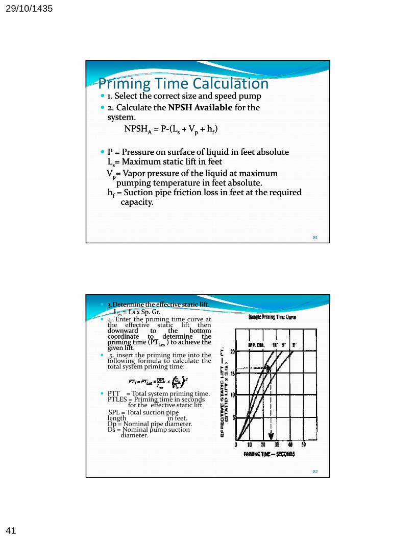
Priming Time Calculation 11. Select the correct size and speed pump . Select the correct size and speed pump
22. Calculate the . Calculate the NPSH AvailableNPSH Available for the for the system. system. yy
NPSHNPSHAA = P= P‐‐(L(Lss + V+ Vpp + h+ hff) )
P = Pressure on surface of liquid in feet absolute P = Pressure on surface of liquid in feet absolute LLss= Maximum static lift in feet = Maximum static lift in feet
VVpp= Vapor pressure of the liquid at maximum = Vapor pressure of the liquid at maximum pumping temperature in feet absolute pumping temperature in feet absolute
81
pumping temperature in feet absolute. pumping temperature in feet absolute. hhff = Suction pipe friction loss in feet at the required = Suction pipe friction loss in feet at the required capacity. capacity.
33.Determine the effective static lift. .Determine the effective static lift. LLeses = Ls x Sp. Gr.= Ls x Sp. Gr.
4. Enter the priming time curve atthe effective static lift thendownwarddownward toto thethe bottombottomcoordinatecoordinate toto determinedetermine thetheprimingpriming timetime (PT(PTLesLes )) toto achieveachieve thethegivengiven liftlift..
5 insert the priming time into the 5. insert the priming time into thefollowing formula to calculate thetotal system priming time:
PTT = Total system priming time. PTLES = Priming time in seconds for the effective static lift SPL = Total suction pipe l th i f t
82
length in feet. Dp = Nominal pipe diameter. Ds = Nominal pump suction diameter.


![Cavitation and PUmp NPSHr[1]](https://img.dokumen.tips/doc/110x75/5514a9aa497959ee1d8b481f/cavitation-and-pump-npshr1.jpg)