Embed Size (px)
Citation preview
8/20/2019 Flow analysis of centrifugal pump using CFX solver and remedies for cavitation mitigation
http://slidepdf.com/reader/full/flow-analysis-of-centrifugal-pump-using-cfx-solver-and-remedies-for-cavitation 1/7
Dr. G. Rambabu et al. Int. Journal of Engineering Research and Applications www.ijera.com
ISSN: 2248-9622, Vol. 5, Issue 7, (Part - 3) July 2015, pp.52-58
www.ijera.com 52 | P a g e
Flow analysis of centrifugal pump using CFX solver and remediesfor cavitation mitigation
Dr. G. Rambabu*, S. Sampath** G. Karthik*** S. Siva Teja**** *(Department of Mechanical Engineering, Andhra University College of Engineering, A.U.C.E(A),
Visakhapatnam-530003
** (Department of Mechanical Engineering, Andhra University College of Engineering, A.U.C.E(A),
Visakhapatnam-530003
***Department of Mechanical Engineering, Andhra University College of Engineering, A.U.C.E(A),
Visakhapatnam-530003
*****Department of Mechanical Engineering, Andhra University College of Engineering, A.U.C.E(A),
Visakhapatnam-530003
ABSTRACT
In this scholarly thesis pertinent to the working of centrifugal pump, a CFD solver namely CFX is employed in
order to simulate fluid flow characteristics with well-defined constraints and boundary conditions defining the
problem. Stringent solid model is meticulously prepared encompassing the present day usage and constructional
features of a centrifugal pump and is constrained with various boundary conditions having fixed domain in order
to evaluate plots and results. To spearhead and facilitate this analysis program a numerical approximation tool
with high degree of convergence rate called ANSYS 15.0 software is used. The ASNYS software avoids tedious
calculations presumably impending in the design procedure and uses ultimate numerical tool to approximate thesolution of the partial differential equations associated with continuity, momentum and energy phases of a flow
problem in a 3-D model. This exquisite feature of ANSYS enables designer to optimize the design procedure inan iterative manner based on the final plots of post-processing phase. In addition, the scholarly writing also
constitutes the appraisal of the most debilitating and painstaking problem retarding the efficiency of the
centrifugal pump known as cavitation. Possible remedies for overcoming this problem will be indirectly inferredfrom the various plots and figures derived from the post -processing phase of the design process.
Keywords - Cavitation, NPSH, CFD.
I. Introduction
(What is cavitation?)Cavitation is the formation and subsequent
collapse or implosion of vapor bubbles inside the
pump. It occurs because the absolute pressure of the
liquid drops below the liquid's vapor pressure. When
vapor bubbles collapse with enough frequency, it
sounds like marbles and rocks are moving through
the pump. If larger number of vapor particles
accumulate they become irresistible and causes
indentation on the surface encompassing the pump
leading to pitting action. This pitting action corrodes
the metal leading to noisy operation of the pump and
sometimes leads to massive explosion. Cavitation is
a painstaking problem in today's commercial usage
of pump and must be avoided to avert any
retardation in the functioning of the pump.
Cavitation is bound to lower the efficiency of the pump. If the pump operates under cavitating
conditions for rough times, the following can occur:
Pitting marks on the impeller blades and on the
internal volute casing of the pump.
Premature bearing failure.
Shaft breakage and other fatigue failures in the
pump.
Pre-mature mechanical failure.
Factors perpetrating cavitation in a pump:
Fall of absolute pressure at the suction nozzle
below the saturation vapor pressure
corresponding to ambient temperature of the
water.
An increase in the temperature of the pumped
liquid.
An increase in the velocity or flow of the fluid.
Separation and reduction of the flow due to a
change in the viscosity of the liquid.
Undesirable flow conditions caused by
obstructions or sharp elbows in the suction
piping. The pump is inadequate for the system.
RESEARCH ARTICLE OPEN ACCESS
8/20/2019 Flow analysis of centrifugal pump using CFX solver and remedies for cavitation mitigation
http://slidepdf.com/reader/full/flow-analysis-of-centrifugal-pump-using-cfx-solver-and-remedies-for-cavitation 2/7
Dr. G. Rambabu et al. Int. Journal of Engineering Research and Applications www.ijera.com
ISSN: 2248-9622, Vol. 5, Issue 7, (Part - 3) July 2015, pp.52-58
www.ijera.com 53 | P a g e
II. Estimation and prediction of cavitationA powerful tool to access the demerits of a
centrifugal pump is the net positive suction head
denoted as NPSH. This tool helps in the evaluation
of the toughest pain staking problem entangled in theoperating condition of the centrifugal pump. Net
positive suction head is defined as the minimum
head required at any point of the centrifugal pump to
avoid cavitation. It is the energy in the liquid
required to overcome the friction losses from the
suction nozzle to the eye of the impeller without
causing vaporisation. It is a characteristic of the
pump and is indicated on the pump's curve. It varies
by design, size, and the operating conditions. It is
determined by a lift test, producing a negative
pressure in inches of mercury and converted into
feet of required NPSH. According, to the standards
of hydraulic institute, a suction lift test is performedon the pump and the pressure in the suction vessel is
lowered to the point where the pump suffers a 3%
loss in the total head. This point is called the NPSHr
of the pump.
Generally, this net positive suction head theory isonly applicable to the eye and suction of the impeller
only because the vapor pressure at running
conditions is highly capricious due to the advent of
the frictional head loss and its conversion into heat
energy leading to a rise in the temperature of the
liquid. This ultimately decreases the vapor pressure.Moreover, the vapor pressure distribution is not
stagnant throughout the impeller plane and thus NPSH is not applicable to the total portion of the
pump.
+ (1)
where,
p1- absolute pressure at inlet.
pv1- vapor absolute pressure.
C- velocity at inlet.
p- density of liquid.
g- acceleration due to gravity.
and moreover,
(2)
where, NPSHr- net positive suction head required. NPSHa- net positive suction head available.
Following are the exquisite features of NPSH:
Prediction of cavitation and its evaluation.
Determining the necessary NPSH inorder toovercome cavitation at all working conditions of
the pump.
Evaluating the required NPSH by adding 3 feet
head to the available NPSH.
III. What is CFD?Computational fluid dynamics has certainly
come of age in industrial applications and academic
research. In the beginning, this popular field of
study, usually referred to by its acronym CFD, was
only known in the high-technology engineering
areas of aeronautics and astronautics, but now it is becoming a rapidly adopted methodology for solving
complex problems in modem engineering practice.
CFD, which is derived from the disciplines of fluidmechanics and heat transfer, is also finding its way
into important uncharted areas, especially in process,
chemical, civil, and environmental engineering.
Construction of new and improved system designs
and optimization carried out on existing equipment
through computational simulations are resulting in
enhanced efficiency and lower operating costs. With
the concerns about global warming and the world’s
increasing population, engineers in power-generation industries are heavily relying on CFD to
reduce development and retrofitting costs. These
computational studies are currently being performed
to address pertinent issues relating to technologiesfor clean and renewable power as well as formeeting strict regulatory challenges, such as
emissions control and substantial reduction of
environmental pollutants. The fundamental basis of
almost all CFD problems are the Navier – Stokes
equations, which define any single-phase (gas or
liquid, but not both) fluid flow. These equations can be simplified by removing terms describing viscous
actions to yield the Euler equations. Further
simplification, by removing terms describing
vorticity yields the full potential equations. Finally,
for small perturbations in subsonic and supersonic
flows (not transonic or hypersonic) these equationscan be linearized to yield the linearized potential
equations.
3.1 Computational fluid dynamics can be
summarized as follows
An approximate numerical tool used to solve 3-
D fluid flow problems whose solution hasgreater degree of convergence to the exact
solution.
An analyzer in optimizing the design procedure
by constructing its own contingent objective
function which is governed by some typicalfluid flow parameters.
A bundle of database helpful in simulating theflow characteristics of any fluid described in it.
An authentic tool which avoids the tedious,
long-winded calculations in determining the
exact solution of various partial differential
equations for a given boundary condition
stipulated by the user.
3.2 Application of CFD
In, designing Aircrafts and its aerofoiled shape
wings, tail etc for given Mach number and the
type of flow associated with it which may be
sonic, sub-sonic, super-sonic.
For, designing pumps and turbines by
simulating and imparting the desired fluid flow
conditions and characteristics.
8/20/2019 Flow analysis of centrifugal pump using CFX solver and remedies for cavitation mitigation
http://slidepdf.com/reader/full/flow-analysis-of-centrifugal-pump-using-cfx-solver-and-remedies-for-cavitation 3/7
Dr. G. Rambabu et al. Int. Journal of Engineering Research and Applications www.ijera.com
ISSN: 2248-9622, Vol. 5, Issue 7, (Part - 3) July 2015, pp.52-58
www.ijera.com 54 | P a g e
In Estimation and optimization of a design
procedure pertinent to various fluid flowdevices and machines.
For designing and analyzing of the finned
structure encapsulating the motor cycle engine. In the appraisal and analysis of complex
structures by integrating with other simulation
analysis programs aided by the ANSYSSOFTWARE.
3.3 CFD approach and problem solving
methodology
There are generally three phases involved in the
problem solving strategy adopted by any analysis
problem. Each phase of this methodology is a
rudimentary and an unavoidable procedure for
having the desired outcome of best simulation
results predicted by the software before-hand
without an inclination to the destructive testinganalysis. The following are the three phases
associated with any ANSYS problem:
o Pre-Processing Phase:
The geometry (physical bounds) of the problem
is defined.
The volume occupied by the fluid is dividedinto discrete cells (the mesh). The mesh may be
uniform or non-uniform.
The physical modeling is defined- for example,
the equations of motion + enthalpy + radiation +
species conservation.
Boundary conditions are devised. This involvesspecifying the fluid behavior and its properties
at the boundaries of the problem. For transient
problems, the initial conditions are also defined.
o Processing Phase:
The simulation is started and the equations are
solved iteratively as a steady-state or transient.
This phase is totally dependent upon the
processing speed and type of processor
employed in the work station.
o Post-Processing Phase:
Finally a postprocessor is used for the analysis
and visualization of the resulting solution.
This phase usually constitutes various plots and
graphs contingent to the fluid flow problem being analyzed.
The solver's analysis comes under the post
processing phase of the CAD/CAM procedure after
completing the Geometric modeling and physics
definition of the problem. Actually, CFD is a
misnomer for the computing solver in analyzingvarious fluid flow problems. But the actual tool or
solver used for computing fluid flow problems is the
ANSYS SOFTWARE and its embedded tools.ANSYS is an integrated software gleamed from
various sources, database for performing wide range
analysis, optimization of design which not only
include fluid flow analysis but also convoluted problems associated with Civil structural analysis,
Heat flow analysis, Dynamic analysis, Kinematic
analysis, Electromagnetic problems etc. Varioussolvers incorporated in ANSYS for fluid analysis
are:
Fluid Flow- Blow Molding (Polyflow)
Fluid Flow- Extrusion (Polyflow)
Fluid Flow (CFX)
Fluid Flow (Polyflow)
IV. Pre-processing phase:Pre-Processing phase as described before deals
with Geometric modeling, Meshing- mesh
generation, mesh gradation, density, and lastly
comes in defining the physics of the given fluid flow
problem. The pre-processing phase serves as back bone of CAD/CAM processes and helps in providing
better visual interface to the user integrating the
graphics system along with the various periphery
devices present in the work station. A typical
workstation defining geometric modeling and mesh
generation constitutes the following items:
Graphics system and software.
Periphery devices like-plotters, mouse,keyboard, monitor, digitizer, printers etc.
CATIA software.
The pre-processing stage constitutes the crux of all
the three phases describing the 3-D geometric model
of the design process which helps in simulating the physics in the analysis stage. In addition it also helps
in gridding the complex problem to a more facile
one constituting the replica of the same element for
quick generation of results. The pre-processing stage
or phase comprises the following three indispensible
elements:
Geometric modeling
Mesh generation
Physics definition
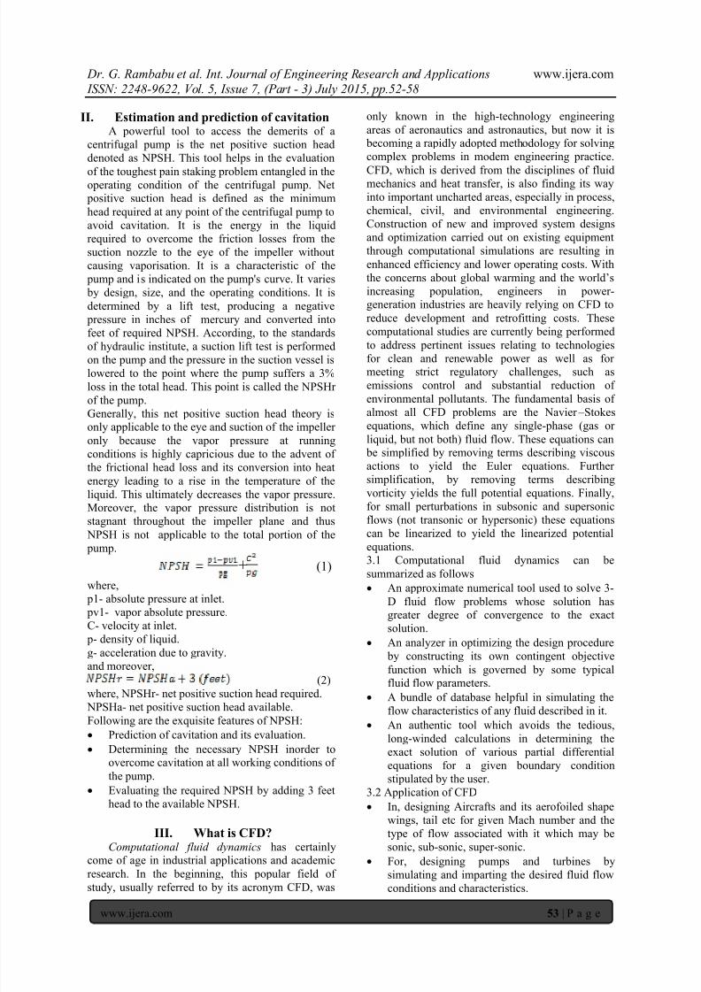
The final facade of the drawing encompassing
present day constructional features of a centrifugal
pump is shown in the figure 4.1. The model includesan inlet, an outlet or discharge, impeller and a casing
circumventing it and is made keeping in mind the
present day constructional features of a centrifugal
pump.
Fig 4.1
8/20/2019 Flow analysis of centrifugal pump using CFX solver and remedies for cavitation mitigation
http://slidepdf.com/reader/full/flow-analysis-of-centrifugal-pump-using-cfx-solver-and-remedies-for-cavitation 4/7
Dr. G. Rambabu et al. Int. Journal of Engineering Research and Applications www.ijera.com
ISSN: 2248-9622, Vol. 5, Issue 7, (Part - 3) July 2015, pp.52-58
www.ijera.com 55 | P a g e
V. Processing phase:Usually, the finite element approach comes
under processing phase of the design procedure
where the actual physics and boundary conditions
are devised and analysis is carried giving adequateresults. However, present day ANSYS software'ssimulating analysis program are capable of handling
all the three phases of the design procedure namely-
preprocessing, processing and post processing where
intricate 3-D models are drawn and sketched with
greater flexibility. Adding, meshing and grid
generation is also incorporated in the software.
5.1 Steps in finite-element procedures
Most generalized procedure for carrying out FEA for
any analysis problem is as follows:
Procedure 1: Discretization Divide the object of
analysis into a finite number of finite elements.
Procedure 2:Selection of the interpolation function Select the element type or the
interpolation function which approximates
displacements and strains in each finite
element.
Procedure 3: Derivation of element stiffness
matrices Determine the element stiffness
matrix which relates forces and displacements
in each element.
Procedure 4: Assembly of stiffness matrices into
the global stiffness matrix Assemble the element
stiffness matrices into the global stiffness matrix
which relates forces and displacements in the
whole elastic body to be analyzed. Procedure 5: Rearrangement of the global
stiffness matrix Substitute prescribed applied
forces (mechanical boundary conditions) anddisplacements (geometrical boundary
conditions) into the global stiffness matrix, and
rearrange the matrix by collecting unknown
variables for forces and displacements, say in
the left-hand side, and known values of the
forces and displacements in the right-hand side
in order to set up simultaneous equations.
Procedure 6: Derivation of unknown forces and
displacements Solve the simultaneous equations
set up in Procedure 5 above to solve the
unknown variables for forces and
displacements. The solutions for unknown
forces are reaction forces and those for
unknown displacements are deformations of the
elastic body of interest for given geometrical
and mechanical boundary conditions,
respectively.
Procedure 7:Computation of strains and stresses
Compute the strains and stresses from the
displacements obtained in Procedure 6
VI.
Post-processing phase:The solution, results and plots obtained in theANSYS software has great significance for the pre-
determined path chosen for analysis. Validation of
the results can be done by Rapid prototyping beforeactual advent of the designed product into the
market. In case of a civil structural problem, element
strains and stresses are the final outcomes of theanalysis along with typical plots depicting the stress
distribution along the whole continuum. The results
and plots obtained in the post-processing phase
depends upon the following factors:
Number of nodes, elements
Type of element chosen
Mesh density and mesh gradation
Number of iterations
6.1 Significance of the plots
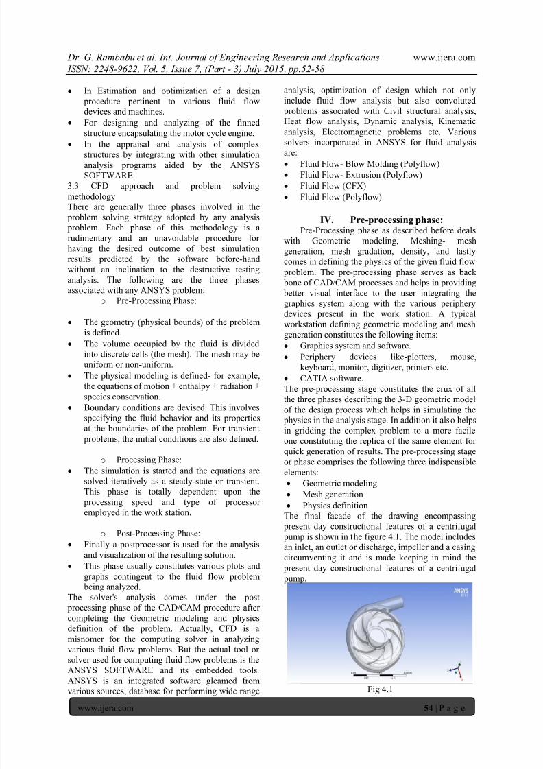
6.1.1 Absolute pressure rotation plot (impeller with
casing)
The following adjacent plot relates the absolute
pressure distribution along the domain of thecentrifugal pump. The red portion depicts the area ofhigh pressure prone region along the volute casing of
the centrifugal pump and the navy blue portion
entails the region of low absolute pressure.
Fig 6.1.1 a
Obviously, it is true that the eye and the inlet of theimpeller i.e the suction region has low pressure
which is to be pressurized to a high pressure zone at
the discharge at outlet. The absolute pressure chart
maps the regions of the lowest pressure plots inorder
to insinuate the presence of saturated vapor pressure
at the eye of the impeller. This will serve as anindication of the cavitation in a pump. The areas of
light blue also represents the scarcity of NPSH
available at that point.
6.1.2 Pressure rotation plot (impeller pad only)
This lucidly depicts how pressure builds up along
the plane of the impeller during the running
conditions of the pump. The light blue portion
encompassing some part of the eye is more prone to
low absolute and have high risks of cavitation in
those areas.

8/20/2019 Flow analysis of centrifugal pump using CFX solver and remedies for cavitation mitigation
http://slidepdf.com/reader/full/flow-analysis-of-centrifugal-pump-using-cfx-solver-and-remedies-for-cavitation 5/7
Dr. G. Rambabu et al. Int. Journal of Engineering Research and Applications www.ijera.com
ISSN: 2248-9622, Vol. 5, Issue 7, (Part - 3) July 2015, pp.52-58
www.ijera.com 56 | P a g e
Fig 6.1.2 a
The impeller is given a specific angular speed and
the pressure distribution plane can be observed
clearly. It must be noted that cavitation tendancy
depends greatly upon the speed of the impeller also.
During rotation the outer edge of the impeller vanes
are subjected to hydraullic stresses and muct be
backed up with intricate contours (which is nothing but the casing) inorder to sustain it.
.6.1.3 Total pressure plot (impeller back portion and
eye)
This plot gives the vulnerable areas of the high
pressure at the interspaces enclosed between thevanes. The interspaces between vanes close to the
discharge have high tendancy to hydraullic stresses
(red region) during the running condition of the
pump where as the interspaces included by the vanes
at gradually increasing cross section of the casing ismore prone to cavitation if the absolute pressure of
the liquid is below vapor pressure of the liquid at
ambient conditions. To have a better comprehensionof the total pressure plot a perspective snapshot is
Fig 6.1.3a
taken which is schematically depicted in the
folowing adjacent Fig 6.1.3 b. The hazy red portion
Fig 6.1.3 b
represents the casing encompassing the impeller and
the discharge tube at outlet. The superimposition ofthe impeller plane and casing plane gives the above
plot and can be validated as more generic form of
interpretation for judging the centrifugal pump's performance.
6.1.4 Total pressure outlet
This plot enables the manufacturers to curtail and
evaluate the performance plots of the pump
depending upon the type of application demanded by
the consumer. The difference between the inlet and
outlet absolute pressure head determines the net
Fig 6.1.4 a
effective head developed by the pump at various
speeds and operating suction head. The
superimposition of all the above plots gives the
following plot shown in figure 6.1 e which is used by the consumer in the manufacturer's catalogue for
choosing a particular type of pump for a givenapplication. The manufacturer's catalogue constitutes
a scale entailing NPSH for a given speed and
discharge head enabling the customer's to have a
greater overview of the pump's commercialexploitation.
6.1.5 Vapor superfical velocity
The most exquisite feature of CFX solver of the
ANSYS software is its ability to map and point the
areas of highest vapor velocity due to the cavitation
phenomenon causing pitting action on the casing andvane material. The vapor velocity flow pattern for a
given speed of the impeller can be easily interpreted
and comprehended. Even though the fluid attains particular pressure energy at the expense velocity
head, there will always be certain disturbances in the
flow due to the advent of cavitation leading to the
fall of pressure energy. This case is most important
pertinent to water which is making its way out of the
impeller with cavitating conditions. Consequently,
high velocity vapor bubbles start hitting the casing
encompassing the impeller, ensuing pitting action.The adjacent plot gives the vapor superfical velocity
at cavitating conditions and infers the places likely
to effect greatly by pitting action of the high velocity
vapor bubbles. The velocity of superficial vapor
bubbles greatly depends on the type of casing andthe angular velocity of the impeller. The red- dashed

8/20/2019 Flow analysis of centrifugal pump using CFX solver and remedies for cavitation mitigation
http://slidepdf.com/reader/full/flow-analysis-of-centrifugal-pump-using-cfx-solver-and-remedies-for-cavitation 6/7
Dr. G. Rambabu et al. Int. Journal of Engineering Research and Applications www.ijera.com
ISSN: 2248-9622, Vol. 5, Issue 7, (Part - 3) July 2015, pp.52-58
www.ijera.com 57 | P a g e
lines showcase the regions with high vapor velocity
for a given speed of the impeller.
Fig 6.1.5 a
VII. Conclusion and scope: There are a number of inferences made from the
plots articulated by the CFD analysis of a centrifugal
pump. Conclusive suppositions are brought down bycontrasting the post-processing plots with different
operating conditions of the centrifugal pump. The
focus should be on resolving cavitation problems
either by increasing the external pressure on the fluid
or decreasing its vapor pressure. The external
pressure could be increased by:
Increasing the pressure at the pump suction
such that the absolute pressure of water at inlet
does not falls below the saturation pressure at
that temperature present in the ambience.
Reducing the energy losses incurring at the eyeof the pump. This can be resolved by using a
frictionless small length suction inlet. Using a larger pump.
Vapor pressure of the fluid is decreased by:
Lowering the temperature of the fluid.
Changing to a fluid with a lower vapor pressure.We are witnessing a renaissance of computer
simulation technology in many industrial
applications. This changing landscape is partly
attributable to the rapid evolution of CFD techniques
and models. For example, state-of-the-art models forsimulating complex fluid-mechanics problems, such
as jet flames, buoyant fires, and multi-phase and/or
multi-component flows, are now being progressively
applied, especially through the availability of multi-
purpose commercial CFD computer programs. The
increasing use of these programs in industries makes
clear that very demanding practical problems are
now being analyzed by CFD. With decreasing
hardware costs and rapid computing times, engineers
are increasingly relying on the reliable yet easy-to-
use CFD tools to deliver accurate results, as
described in the examples in the previous sections.
Additionally, significant advances in virtual
technology and electronic reporting are allowing
engineers to swiftly view and interrogate the CFD
predictions and to make necessary assessments and judgments on a given engineering design. Inindustry, CFD will eventually be so entrenched in
the design process that new product development
will evolve toward “zero-prototype engineering.’'Such a conceptual design approach is not a mere
flight of the imagination, but rather a reality in the
foreseeable future, especially in the automotiveindustry. Looking ahead, full-vehicle CFD models
with undershoot climate control, and external
aerodynamics will eventually be assembled into one
comprehensive model to solve and analyze vehicle
designs in hours instead of days. Time-dependent
simulations will be routinely performed to
investigate every possible design aspect. Other
related “co-simulation" areas in ascertaining the
structural integrity as well as the acoustics of thevehicle will also be computed concurrently with the
CFD models. Engineering judgment will be
consistently exercised on the spot through real-time
assessments of proposed customized designsimulations in selecting the optimum vehicle. In thearea of research, the advances in computational
resources are establishing large eddy simulation
(LES) as the preferred methodology for many tur-
bulence investigations of fundamental fluid-
dynamics problems. Since all real- world flows are
inherently unsteady, LES provides the means ofobtaining such solutions and is gradually replacing
traditional two-equation models in academic
research. The demand for LES modeling is steadily
growing. LES has made significant inroads,
especially in single-phase fluid flows. In combustion
research, LES has also gained much respectability, particularly in capturing complex flame
characteristics because of its better accommodation
of the unsteadiness of the large-scale turbulence
structure affecting the combustion
VIII. Limitations: Although much effort has been focused on
developing more robust CFD models to predict
complicated multi-phase physics involving gas-
liquid, gas-solid, liquid-solid, or gas-liquid-solid
flows, LES (large eddy simulation) remains in its
infancy of application to these flow problems.
Instead, two-equation turbulence models are stillvery prevalent in accounting for the turbulence
within such flows. LES may be adopted as the preferred turbulence model for multi-phase flows in
the future but, in the meantime, the immediate need
is to further develop more sophisticated two-
equation turbulence models to resolve these flows.
Based on current computational resources, numericalcalculations performed through LES can be long and
arduous due to the large number of grid nodal points
required for computations. However, the ever-
escalating trend of fast computing will permit such
calculations to be performed more regularly in the
foreseeable future. Also, with the model graduallymoving away from the confines of academic
8/20/2019 Flow analysis of centrifugal pump using CFX solver and remedies for cavitation mitigation
http://slidepdf.com/reader/full/flow-analysis-of-centrifugal-pump-using-cfx-solver-and-remedies-for-cavitation 7/7
Dr. G. Rambabu et al. Int. Journal of Engineering Research and Applications www.ijera.com
ISSN: 2248-9622, Vol. 5, Issue 7, (Part - 3) July 2015, pp.52-58
www.ijera.com 58 | P a g e
research into the industry environment, it is not
entirely surprising that LES will eventually becomea common method for investigating many physical
aspects of practical industrial flows.
8.1 Following are the limitations of CFD analysis inthis project
The rate of convergence to the exact solution of
the partial differential equations is very low below 100 iterations and high speed computers
are required to enhance and interpret iterations
above 100. Generally, best solution arrives at
400-500 iterations and greatly depends upon the
type of problem chosen.
The remedies suggested for cavitation of thecentrifugal pump relents on the operational
working conditions of the pump and no
constructional optimization details is disclosed
by the project thesis. Cavitation analysis made in this project is
confined to both on-load and off-load phases.
However, it is difficult to infer conclusions
from the on-load characteristics because it is
contingent upon various factors like type of the
casing material, vane material, thermal
properties of the vanes and casing adhering tofrictional head loss resulting in highly
capricious NPSHr (net positive suction head
required).
No methods or remedies are studied regarding
the erroneous vibrations and noise emanated
from the working of a centrifugal pump.
IX. Nomenclature:CFD- computational fluid dynamics.
NPSH- net positive suction head.
NPSHa- net postive suction head available.
NPSHr- net positive suction head rquired.
p1- absolute pressure at inlet.
pv1- vapor absolute pressure.
C- velocity at inlet.
p- density of liquid.
g- acceleration due to gravity.
X.
Acknowledgment:This project thesis and documentation is done
with grim determination under strict tutelage of our
mentor Dr. G. Rambabu and any claims raised by
the third party for a facsimile unauthenticated copy
is merely a coincidence and will be disavowed by
the members of the batch. In addition, any attempts
for emulating this thesis content and analysis will
also be condemned and pertinent legal action will be
sued against the third party. Finally we acknowledge
the contribution of all those who have helped us
directly or indirectly with their good wishes and
constructive criticism which lead to successfulcompletion of our Project.
References:
Journals: [1] Reddy, J.N. (2005). An Introduction to the
Finite Element Method (Third ed.). McGraw-
Hill. journal.[2] Hrennikoff, Alexander (1941). "Solution of
problems of elasticity by the framework
method". Journal of applied mechanics 8.4:
169 – 175.[3] Elman; Howle, V; Shadid, J; Shuttleworth, R;
Tuminaro, R et al. (January 2008). "A
taxonomy and comparison of parallel block
multi-level preconditioners for the
incompressible Navier – Stokes
equations". Journal of Computational Physics 227 (3): 1790 – 1808.
[4] Courant, R. (1943). "Variational methods for
the solution of problems of equilibrium andvibrations". Bulletin of the American
Mathematical Society 49: 1 – 23.
[5] Hirt, C.W.; Nichols, B.D. (1981). "Volume of
fluid (VOF) method for the dynamics of free
boundaries". Journal of Computational
Physics.
Books:[6] CAD/CAM applications by P.N.Rao. [7] Shepard, Dennis G. (1956). Principles of
Turbomachinery. McMillan.[8] Reti, Ladislao; Di Giorgio Martini, Francesco
(Summer 1963). "Francesco di Giorgio(Armani) Martini's Treatise on Engineering
and Its Plagiarists".
[8] Fluid mechanics and hydraulic by Modi and
Seth [9] Centrifugal pump design by John Tuzson
[10] Hirt, C.W.; Nichols, B.D. (1981). "Volume of
fluid (VOF) method for the dynamics of free
boundaries". Journal of Computational
Physics.
[11] Unverdi, S. O; Tryggvason, G.(1992). "AFront-Tracking Method for Viscous,
Incompressible, Multi-Fluid Flows". J.
Comput. Phys.[12] Benzi, Golub, Liesen (2005). "Numerical
solution of saddle-point problems". Acta
Numerica 14:1 – 137.
.
![Proceedings of the Second Middle East Turbomachinery ......the ANSYS-CFX solver, [ANSYS CFX-12.1, 2010]. The homogeneous two-phase mixture model is employed to model cavitation. The](https://img.dokumen.tips/doc/110x75/60b327ef9589750bfe1e3fd5/proceedings-of-the-second-middle-east-turbomachinery-the-ansys-cfx-solver.jpg)