Embed Size (px)
Citation preview
Abstract— In today’s fast-paced world, engineers need the best
tools available to solve their measurement challenges quickly and accurately. There are many types of oscilloscope available in the market. The main types of oscilloscopes are analog oscilloscope, digital oscilloscope and PC based oscilloscope. From which the digital oscilloscope are widely used now a days due there accuracy portability, high speed, high resolution, data storing capability etc. here we provide an alternative solution which is basically a digital oscilloscope with almost all the control options which any standard digital oscilloscope has. It has basically three large blocks, first is the ADC part which has the analog to digital IC which is controlled by the STK500 AVR kit. Second is the oscillator control part which is implanted on the FPGA Spartan 3 kit. It has the entire storage element and the user input control and driver part of IC and VGA. The third large block is display device which is a CRT monitor along this the LEDs and seven segment display part on FPGA is also used to display information. So this is a cheap alternative to expensive oscilloscopes; using a VGA display and a simple mouse interface, a user can use this scope to look at and measure signals up to about 80 MHz if an extra high frequency clock will provide to the design. Keywords- ADC(Analog To Digital IC), FPGA Spartan 3 kit, VGA Display.
I INTRODUCTION
This digital oscilloscope provides a cheap alternative to expensive oscilloscopes; using a VGA display and a simple mouse interface, a user can use this scope to look at and measure signals up to about 80Mhz. this kind of scope would be ideal for hobbyists and students looking to learn and debug circuits. Development is based on the Spartan III Starter Kit from Xilinx. The ADC is simply controlled by an MCU (another starter kit: the ATK400 from Atmel) but will soon be controlled by the FPGA (to achieve the faster speeds). In the future, schematics and PCB layout binaries will be available. 1. Features • Timescale selection • Selectable trigger (Rising, Falling / Normal, Single, Auto) • Horizontal and Vertical position offsets • Grid Display On/Off/Outline
• Semi-standard Oscilloscope look and feel • VGA display; drives a standard computer monitor • PS/2 Mouse User Interface • 9-bit input data width • Developed specifically for the Spartan III development kit from Xilinx.
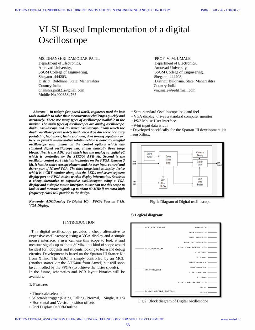
Fig 1: Diagram of Digital oscilloscope 2) Logical diagram:
Fig 2: Block diagram of Digital oscilloscope
VLSI Based Implementation of a digital Oscilloscope MS. DHANSHRI DAMODAR PATIL PROF. V. M. UMALE Department of Electronics, Department of Electronics, Amravati University, Amravati University, SSGM College of Engineering, SSGM College of Engineering, Shegaon 444203, Shegaon 444203, District: Buldhana, State: Maharashtra District: Buldhana, State: Maharashtra Country:India Country:India [email protected] [email protected] Mobile No.9096584765
33
INTERNATIONAL CONFERENCE ON CURRENT INNOVATIONS IN ENGINEERING AND TECHNOLOGY
INTERNATIONAL ASSOCIATION OF ENGINEERING & TECHNOLOGY FOR SKILL DEVELOPMENT
ISBN: 378 - 26 - 138420 - 5
www.iaetsd.in

3) Functional Description: The digital oscilloscope processes the digital data and shows it on the VGA. This is thus have three large block, these are: 1. ADC converter 2. Display device 3. controller part (FPGA part) ADC converter: This block has an analog to digital IC to convert the input analog signal into its equivalent digital Signal. The ADC is simply controlled by an MCU (another starter kit: the ATK500 from Atmel) but will soon be controlled by the FPGA (to achieve the faster speeds). The digital data from ADC then goes to the FPGA Spartan 3 kit
Fig 3: Block diagram of ADC Driver part Display (CRT) Monitor: This is the display devise at which the signal waveform is displayed .in this project I use the CRT monitor as display device. FPGA Spartan Kit Block: In this block the digital data is processed and synchronizing with ADC IC this block is very important and has many other processing blocks which are: ADC Data Buffer: This block has buffer the data so that the continuous waveform can be seen on VGA. It also has the time scale option so that the data can be read from the RAM at different frequency speed according to the user or signal.
Fig 4: Block diagram of ADC Data Buffer Part Character Display Driver: The signal is display on VGA. But some information is given on the seven segment display about the signal and the working mode thus the character display part is used for this purpose. Mouse Driver: The user define values are needed to control the oscilloscope such as time scale, vertical offset, triggering style etc. thus a input device is needed to give the input in This project this block use mouse as PS2 format to give user input.
Fig 5: Block diagram of Mouse Driver Part VGA Driver: The output is shown on the VGA. Thus this block need the VGA driver to control the CRT monitor and show the wave for on the monitor. So this block have to generate some signals as vertical synchronizing and horizontal synchronizing for scanning and RGB for color except this there are many other character and user line which divide the screen for measuring purpose thus this block have to also generate these fixed lines.
34
INTERNATIONAL CONFERENCE ON CURRENT INNOVATIONS IN ENGINEERING AND TECHNOLOGY
INTERNATIONAL ASSOCIATION OF ENGINEERING & TECHNOLOGY FOR SKILL DEVELOPMENT
ISBN: 378 - 26 - 138420 - 5
www.iaetsd.in

Fig 6: Block diagram of VGA Driver Part Seven Segment Driver: The analog to digital converted data can also see on FPGA board this is done by seven segment display present on Spartan 3 kit. The digital data is shown on two seven segment block in hexadecimal format. VGA Data Buffer: The signal which is shown on VGA display is stored in RAM in digital from. Thus for continuous viewing of the waveform it is necessary to store the data and retrieve it time to time. This is done by this block in this block there RAM is built in FPGA and data is stored in it. Mouse user Input Driver: In this oscilloscope the input is given by mouse so this block is control the user input and gives the signals to display and control the waveform showing on the VGA display. DCM (Digital Clock Manager): The function of this block is to control the clock and removes the problem of clock skew.
II. SYNTHESIS REPORT
Device utilization summary: Selected Device: 3s200ft256-4
III. FUTURE SCOPE
The purposed design is having great future possibility. Following are the some feature that can be added in this design • FFT display • Measurement Display (amplitude, frequency) • Cursors • Vectors • Multi-channel display (up to 8) • Channel Math • UART or USB computer communication (data export)
IV. CONCLUSION
The usefulness of an oscilloscope is not limited to the world of electronics. With the proper transducer, an oscilloscope can measure all kinds of phenomena. Oscilloscopes are used by everyone from physicists to television repair technicians. An automotive engineer uses an oscilloscope to measure engine vibrations. A medical researcher uses an oscilloscope to measure brain waves. The digital oscilloscopes are generally having very high costs. The proposed design provides a cheap alternative to expensive oscilloscopes; using a VGA display and a simple mouse interface, a user can use this scope to look at and measure signals up to about 80Mhz.this kind of scope would be ideal for hobbyists and students looking to learn and debug circuits.
V. REFERENCE
[1] Pereira, J.M.D., “The history and technology of oscilloscopes”, Instrumentation & Measurement Magazine, IEEE Volume 9, Issue 6, 2006 [2]Oscilloscope Types: http://www.radioelectronics.com/info/t_and_m/oscilloscope/ oscilloscope_types.php [3] “Hawkins Electrical Guide”, Theo. Audel and Co., 2nd ed. 1917, vol. 6, Chapter 63: Wave Form Measurement, pp. 1841-2625 [4] XYZ of Oscilloscopes Tutorial http://www.tek.com/Measurement/ programs/301913X312631/?lc=EN&PRODUCT=&returnUrl=ct=TI &cs=pri&ci=2280&lc=EN [5] Bhunia C, Giri S, Kar S, Haldar S, Purkait P, “A low-cost PC-based virtual oscilloscope”,Education, IEEE Transactions on Volume 47, Issue 2, May 2004. [6] Moschitta A, Stefani F, Petri D, “Measurements of Transient Phenomena With Digital Oscilloscopes”, Instrumentation and Measurement, IEEE Transactions on, Volume 56, Issue6, Dec. 2007 Page(s):2486 - 2491 [7] English W.O., “Digital Storage Oscilloscope vs. Digital Multimeter”, Industrial and Commercial Power Systems Technical Conference, 2006 IEEE. [8] Hengkietisak S, Tipyakanont S, Tangsiriworakul C, Manop C, Senavongse W, “Laboratory digital signal analysis with virtual [9] Rapid Prototyping of Digital Systems, book by James o. Hamblen and Michael d. Furman, page(s) 134-151
35
INTERNATIONAL CONFERENCE ON CURRENT INNOVATIONS IN ENGINEERING AND TECHNOLOGY
INTERNATIONAL ASSOCIATION OF ENGINEERING & TECHNOLOGY FOR SKILL DEVELOPMENT
ISBN: 378 - 26 - 138420 - 5
www.iaetsd.in
4
[10] Kuenzi C.D., Ziomek C.D., Fundamentals of Oscilloscope Measurements in Automated Test Equipment (ATE), Systems Readiness Technology Conference, IEEE, 18-21 Sept. 2006 Page(s):244 – 252 [11] Lembeye Y., Keradec J.P., Cauffet G., ‘Improvement in the linearity of fast digital oscilloscopes used in averaging mode Instrumentation and Measurement’, IEEE Transactions on Volume 43, Issue 6, Dec. 1994 Page(s):922 – 928 [12] Moschitta A., Stefani F., Petri D., “Measurements of transient phenomena with digital oscilloscopes” Instrumentation and Measurement Technology Conference, 2003. IMTC '03. Proceedings of the 20th IEEE Volume 2, 20-22 May 2003 Page(s):1345 - 1349 vol.2
36
INTERNATIONAL CONFERENCE ON CURRENT INNOVATIONS IN ENGINEERING AND TECHNOLOGY
INTERNATIONAL ASSOCIATION OF ENGINEERING & TECHNOLOGY FOR SKILL DEVELOPMENT
ISBN: 378 - 26 - 138420 - 5
www.iaetsd.in