Embed Size (px)
Citation preview
Mini Project Presentation
Design of Automated Teller Machine Controller
Aim of the Project
Design of Automated Teller Machine Controller
Objectives of the Project
To review the literature for understanding the Automated Teller Machine Controller realization for RTL Modeling
To arrive at the design specifications for architecture based on reviewed literature for intended application
To design Verilog module for controller and perform behavioral simulation
To Synthesis the design using the FPGA flow and perform implementation
Methods and Methodology
Verilog model will be developed for selected architecture
Functionality of the design will be verified using test bench in Modelsim
Performance of the design with the required specifications will be compared
Synthesis will be performed and the gate level net list will be generated using Xilinx
ABSTRACTIn the growing technological world, people want their work
to be very simple in order to save their time. As we know some new technology is becoming popular in banking sector, which is referred as ATMs. It makes the work of people as well as the banking sectors to be easy. ATMs help in providing money to the people nearer to the living area by saving their time so that it becoming very popular.
In this work the development of a Moore machine state diagram of an ATM controller.
. The developed design will be modeled using Verilog HDL language which is a Hardware Description Language (HDL) used to describe a digital system. The verification of developed model will be made by identifying the suitable test cases in a test bench. The simulation will be carried out using Modelsim tool and the intended functionality can be verified with the help of its simulation results and also it can be synthesized using the Xilinx tool.
LANGUAGES USED AND TOOLSVHDL/Verilog HDL
TOOLS REQUIRED:
MODELSIM – Simulation, Xilinx - Synthesis
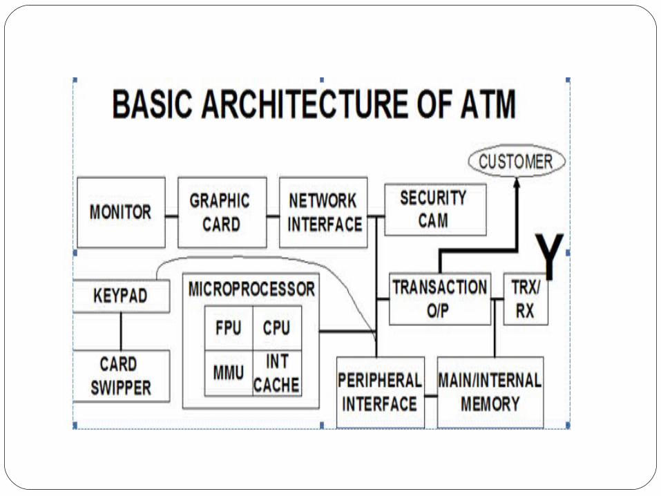
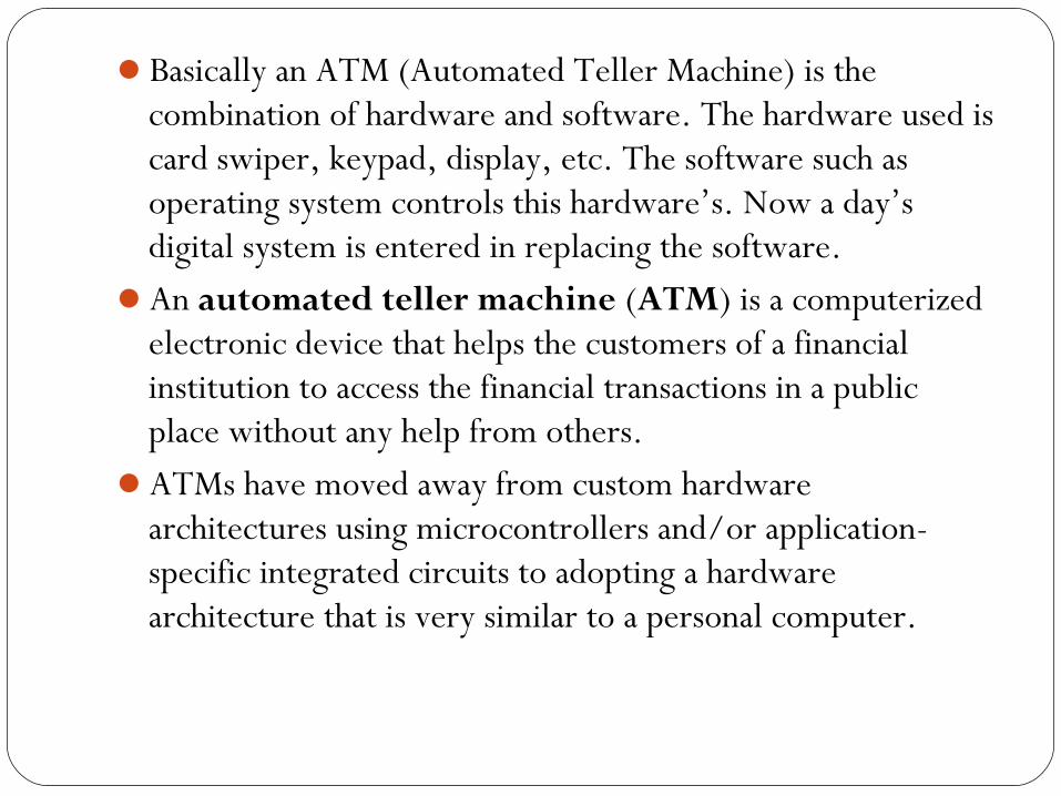
Basically an ATM (Automated Teller Machine) is the combination of hardware and software. The hardware used is card swiper, keypad, display, etc. The software such as operating system controls this hardware’s. Now a day’s digital system is entered in replacing the software.
An automated teller machine (ATM) is a computerized electronic device that helps the customers of a financial institution to access the financial transactions in a public place without any help from others.
ATMs have moved away from custom hardware architectures using microcontrollers and/or application-specific integrated circuits to adopting a hardware architecture that is very similar to a personal computer.
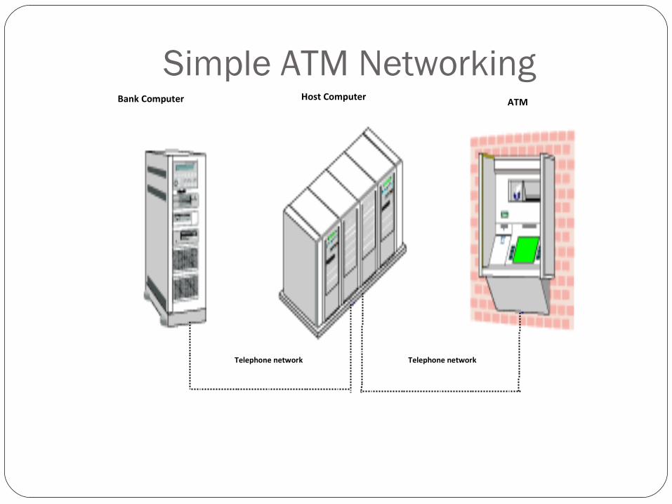
Telephone network Telephone network
Bank Computer Host Computer ATM
Simple ATM Networking
ATM accesses the bank account through telephone networking, a host processor and a bank computer to verify the data. All the operations of ATM are in synchronization in reference to a common clock source. In case of any misconnection between the process steps, the whole transaction is rolled back to effect no change in the account status.
The ATM Controllers are working on windows based operating systems, which also provide ease to designers for programming and modeling its operation. ATM controllers are sophisticated chip elements designed and programmed to make the transaction simple and user-friendly
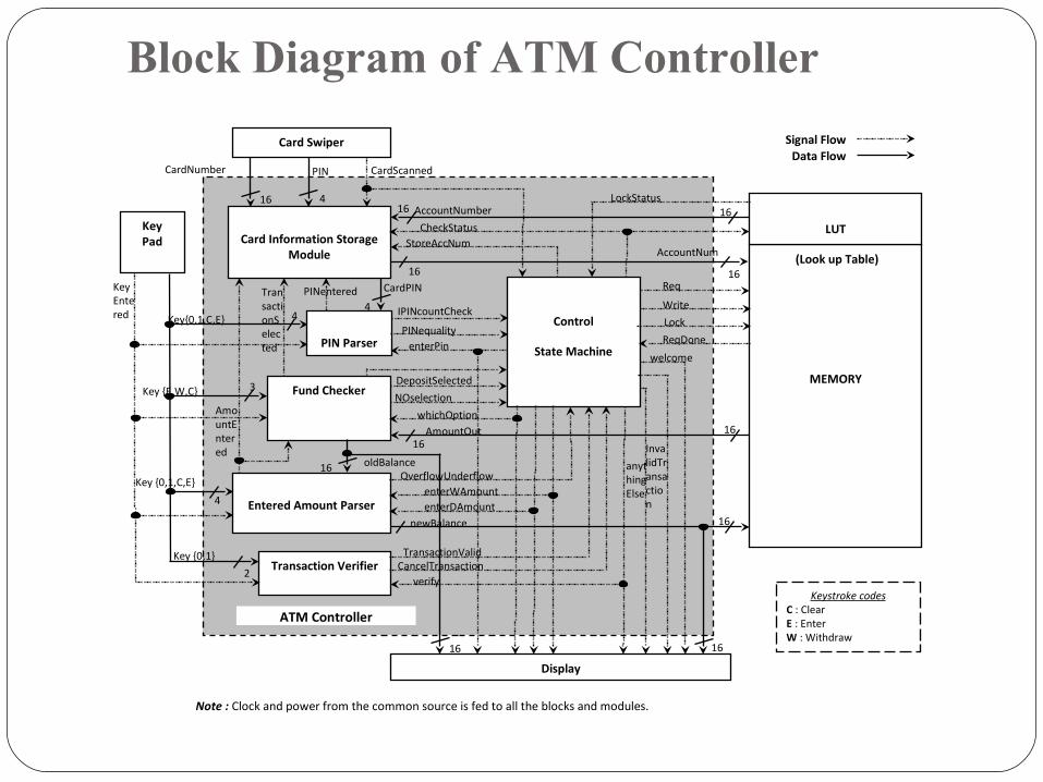
Block Diagram of ATM Controller
Control
State Machine
Signal FlowData Flow
Note : Clock and power from the common source is fed to all the blocks and modules.
PIN Parser
CardScanned
Fund Checker
Entered Amount Parser
KeyPad
MEMORY
Display
LUT
(Look up Table)
Card Information Storage Module
Card Swiper
Transaction Verifier
44
4
3
4
2
16 16
1616
1616
16
16
16 16
16
PINCardNumber
CardPIN
AccountNum
PINentered
enterPin
KeyEntered
Key {0,1,C,E}
TransactionSelected
AmountEntered
CheckStatusStoreAccNum
AccountNumberLockStatus
PINequality
IPINcountCheck
whichOption
DepositSelected
NOselection
oldBalance
AmountOut
enterDAmountenterWAmount
OverflowUnderflow
newBalance
verify
TransactionValidCancelTransaction
Req
Write
Lock
ReqDone
welcome
InvalidTransaction
anythingElse
Key {E,W,C}
Key {0,1}
Key{0,1,C,E}
Keystroke codesC : ClearE : EnterW : Withdraw
ATM Controller
To summarize the operation, the ATM controller is activated on swipe of a card at the card swiper. It then checks its lock status and asks to enter the PIN only when unlocked.
User has to enter the correct PIN within three trials, after which ATM corresponds with the memory to lock the account and no further transaction on the account is possible. On getting the PIN matched, user is asked for the option for the operation he wants to do. For both withdrawal and deposit, he is been provided with the current balance of the account and asked for the transaction amount.
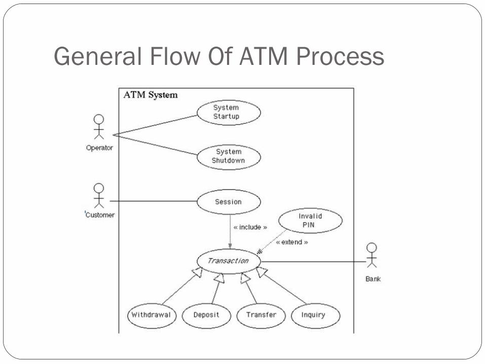
General Flow Of ATM Process
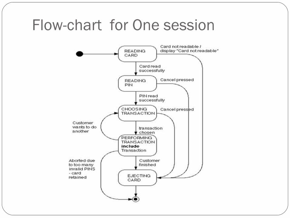
Flow-chart for One session
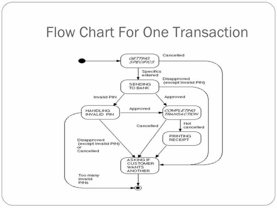
Flow Chart For One Transaction
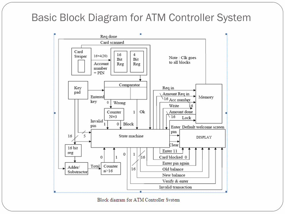
Basic Block Diagram for ATM Controller System
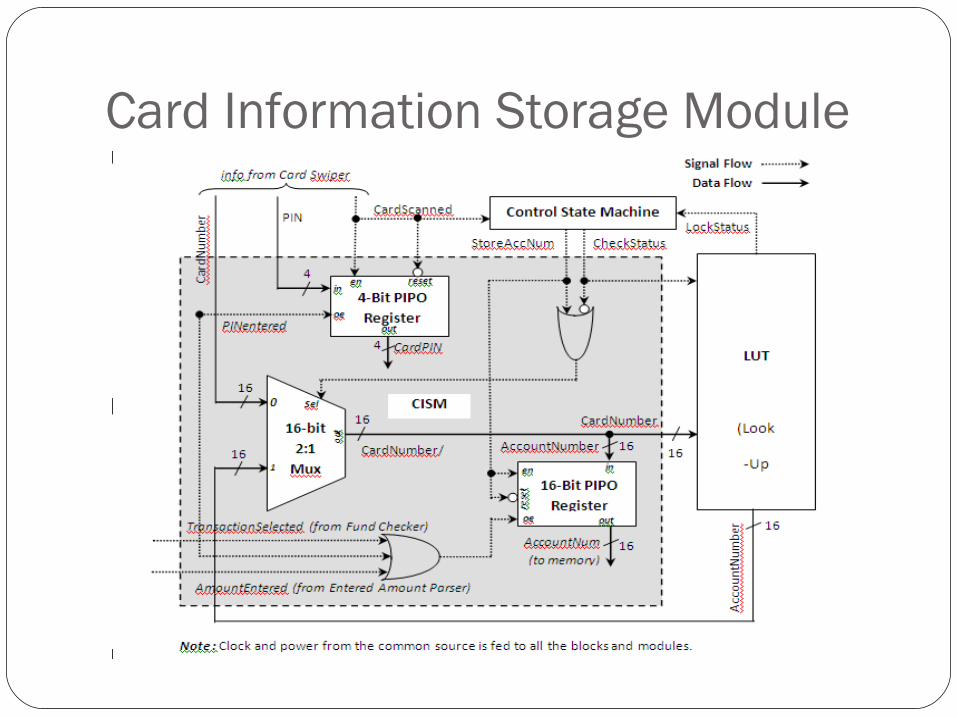
Card Information Storage Module
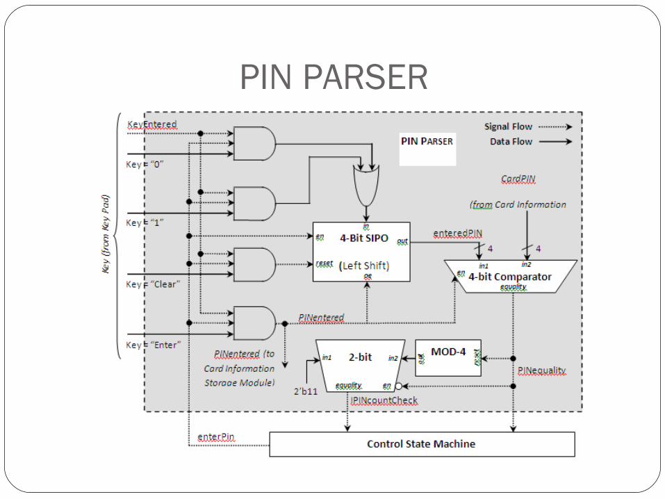
PIN PARSER
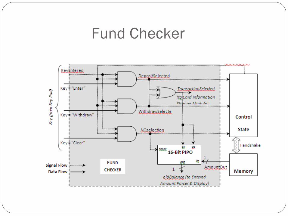
Fund Checker
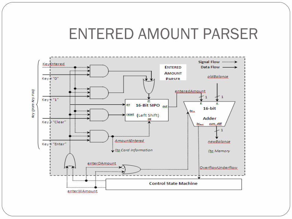
ENTERED AMOUNT PARSER
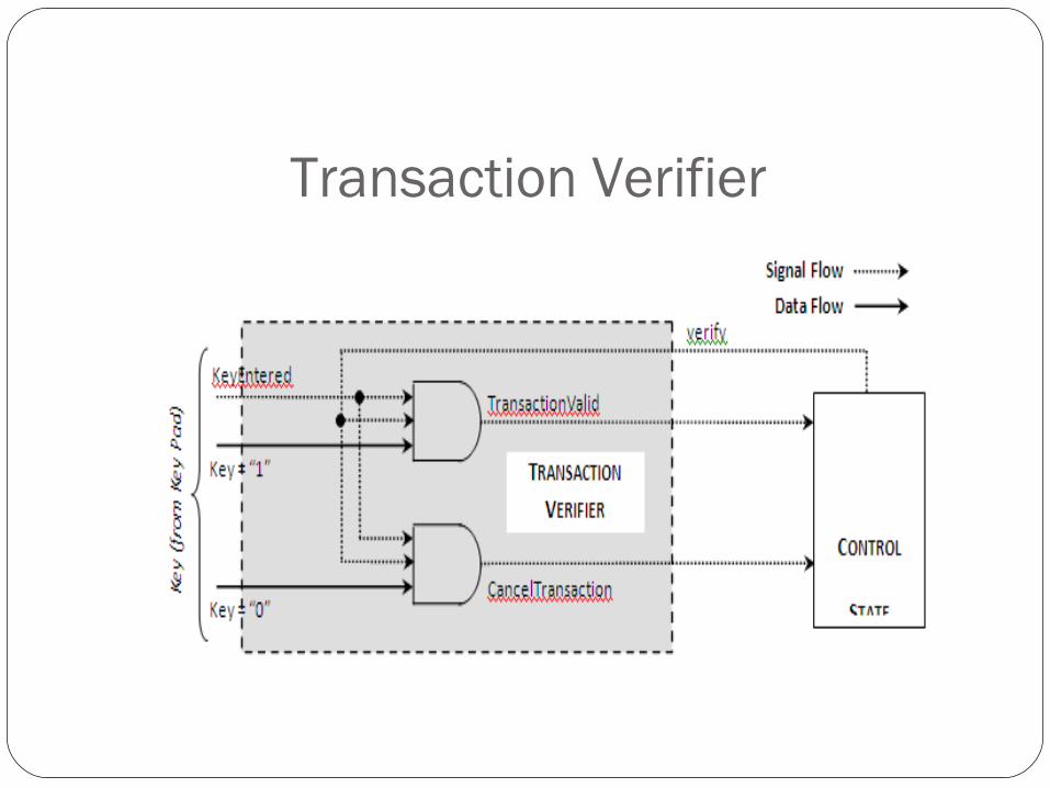
Transaction Verifier
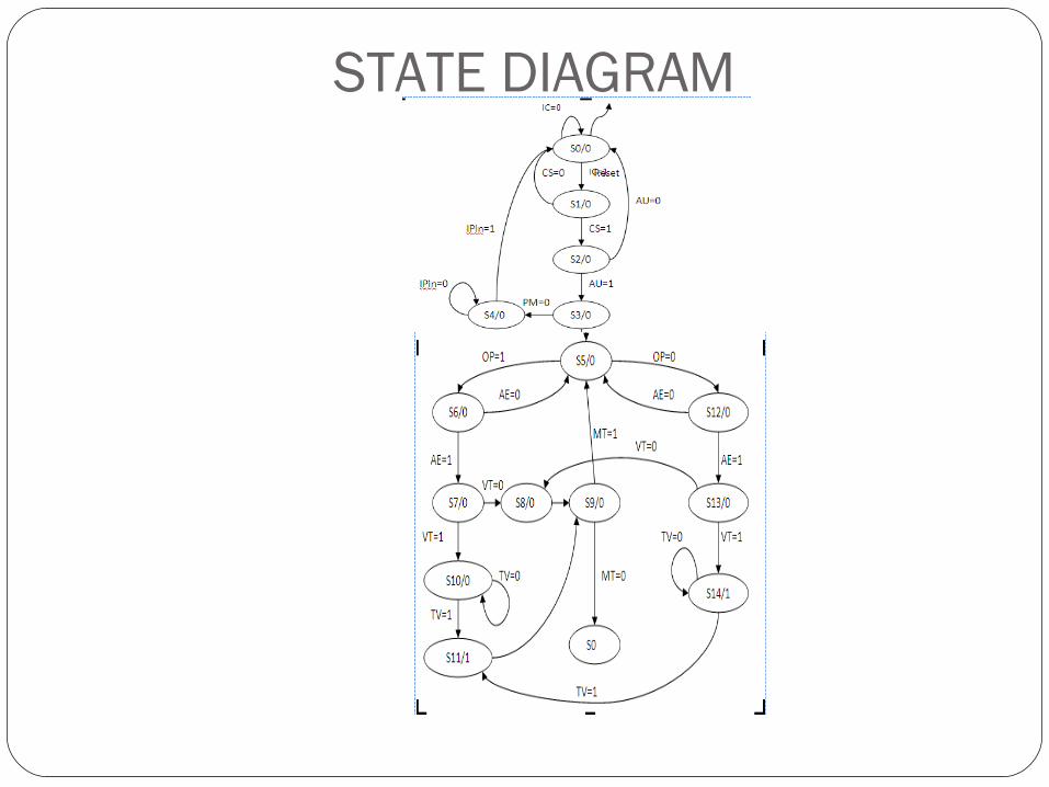
STATE DIAGRAM
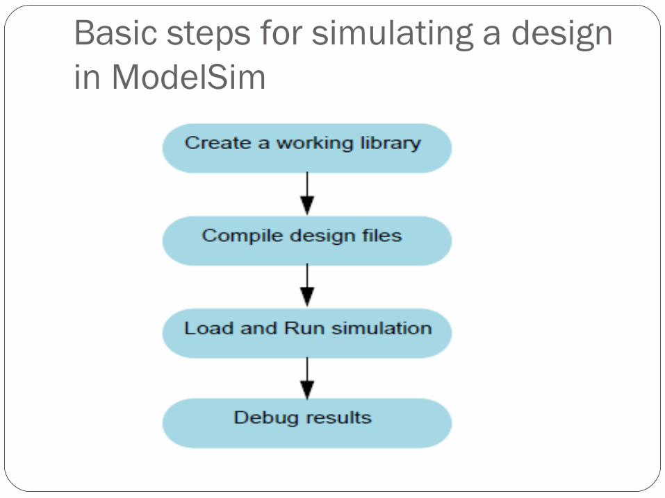
Basic steps for simulating a design in ModelSim
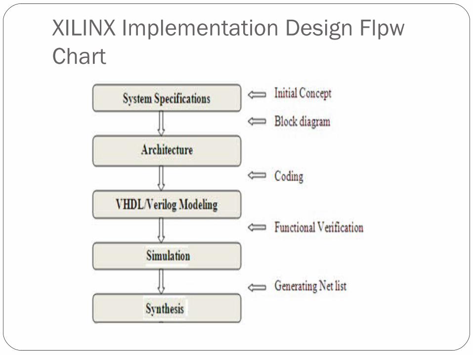
XILINX Implementation Design Flpw Chart
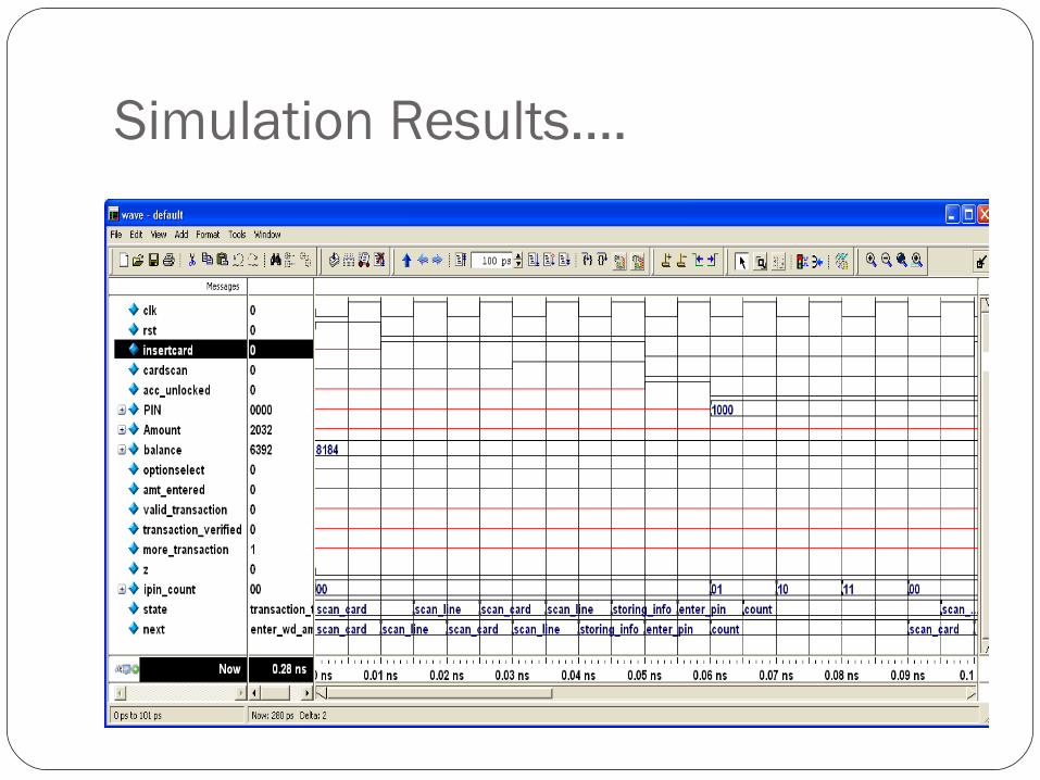
Simulation Results….
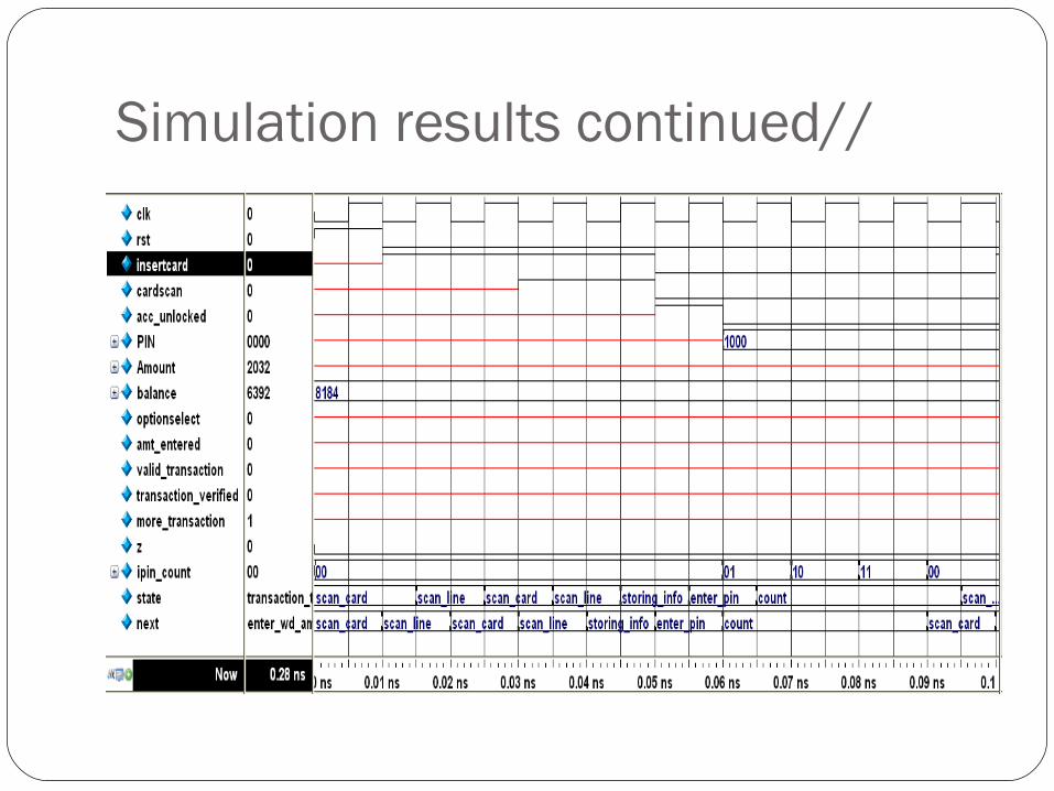
Simulation results continued//
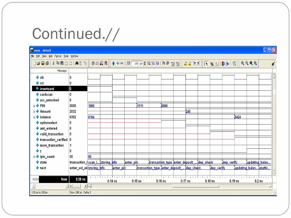
Continued.//
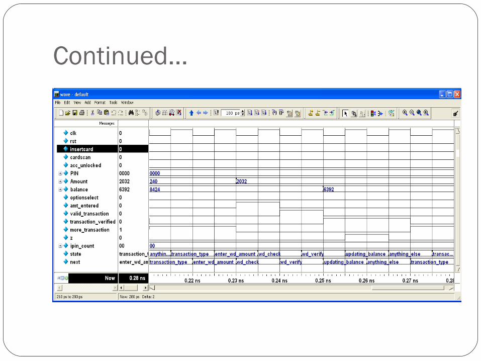
Continued…
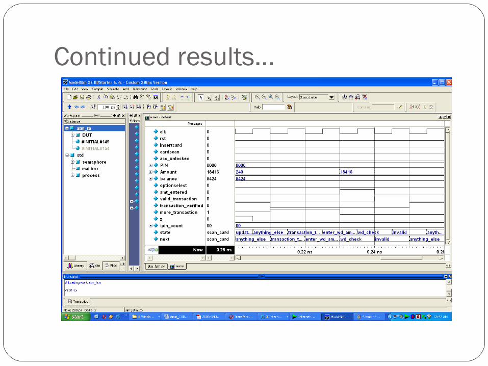
Continued results…
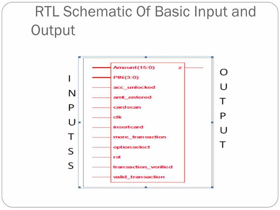
RTL Schematic Of Basic Input and Output
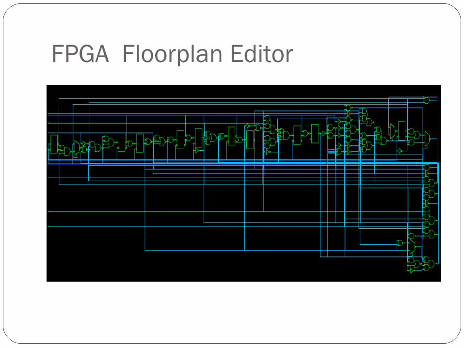
FPGA Floorplan Editor

THANK YOU