UNCLASSIFIED
AD 268 504
ARMED SERVICES TECHNICAL INFORMATION AGENCYARLINGTON HALL STATIONARLINGTON 12, VIRGINIA
UNCLASSIFIED

NOTICE: Ifen government or other drawings, speci-fications or other data are used for any purposeother than in connection with a definitely relatedgovernment procurement operation, the U. S.Government thereby incurs no responsibility, nor anyobligation whatsoever; and tLe fact that the Govern-ment may have formulated, furnished, or in any waysupplied the said drawings, specifications, or otherdata is not to be regarded by implication or other-wise as in any manner licensing the holder or anyother person or corporation, or conveying any rightsor permission to manufacture, use or sell anypatented invention that my in any way be relatedthereto.

mu~izu~S p A.
XEROX
MONITOR{ING AGENCY DOCUMEFNT Ni.AFCRL-981
ASTIA DOCUMENT NIR.
"PROPAGATION CHAIRACq'EHISTIC51 OF A MAGMN.rcG-.ioic D)UCT"
Ing. P). Forvnato A+ Ing. A. nllnr~tni
lFLFNIA ll!.p.A., Vla Tiburtina KMr. 12,'kjo, RoMi., ITALY,
TECHNIWAL (CIE.NTIFIC NOT) NO. 2
CONTRACT NO. AF 61 (052:) -145
may ~ 9,
A S T
C%4
The resep~y oh reported in this document hRS becn sponsored1
hy thp Air Force Cimbride Research Conter of tht, Air Re-
sf-rch nnd Dovelopwnntt "2 mmfnd, United Stntes Air Force,
thr.livb its Furopean of lice.
10911o di

S.p.A.
Abstract
The propagation characteristics of a uniform magneto-
ionic duct of circular cross-section are determined for fre-
quencies higher than. the cyclotron frequency- The ratios (plas-
me wavelength) / (free space wavelength) and (power flowing in
the plasma) / (power flowing outside) are evaluated and discussed
as a function of the diameter / wavelength ratio and of the
plasma permettivity for the propagation of circularly symme-
trical modes.
" The Brillouin diagrams for frequencies higher and lowrr
than the cyclotron frequency are also derived.
Table of contents
Introduction pag
Summary of the previous results
Propagation in the o-a, i , rI region
Propagation in the m< 9,,<o 0<.f€I region
Propagation in the 00 -C o, 0,< <O region
Brillouin diagrams
Bibliography
loglio I di 9

S. p.A.
IntroductioneI
In Technical Note N.1 we have investigated electro-
magnetic wave propagation in a magneto-ionic duct, namely in
a cylindrical plasma of circular cross-section in a static
axial magnetic field, assuming signal frequencies lower than
the cyclotron frequency.
In this Note the same general analysis is 2xtended to
the case of signal frequencies higher than the cyclotron fre-
quency. Here too the discussion Is based on the general Sha-
raeteristie equation and restricted to a uniform, non-atten-
uating plasma and to circularly symmetrical modes; the permet-
tivity tensor is crosen as a constant parameter for each solu-
tion. From these and the previous results we have derived the
- Brillouin diagrams relating the guided and the free space phase
constants for a given set of plasma frequency and cyclotron
frequency values. These diagrams are similar to those derived
with the so-called quasi-static approximatton, except for a
few special features, wh!ch will be described.
1
loglio 2 di q

) Summary of the previous results
The dielectric constant of a uniform plasma, in the
absence of agitational or drift motion, placed in a steady-
state magnetic field B directed along-the positive r(i,l -3)
axis, is a tensor //cf// defined by the formula:
D.-., E9
where
S il. _ (I)
n - electron density
". m - electron mass
e a-electron charge
4 From the equations(1), one can easily find the follow-
Ing relation Amaong , , m and r,
a i~e__ __a, -- - - 0,,,( ,-s L
And we take a system or cylindrical orthogonal coordinates
P, J/ tI where the z axis is parallel to i and with the some
~.lE
orientation, the Maxwell equations can be solved and the feld
equmttons for the etularly symmetrical mods written flo
loglio r didina

S. p. A.
Inside the plasma:
0 / f/;4 t) + X*Ii
3LE B £s 'A,:..r/,( SJ
ir C 2. -01 -T, ,,ol,/e l XIv
TA F/R) A (X, j, AS
1-4 ~ : - E*f Ag(/) 1 J,(/,f/
- -'--' V
)r
whr r,: /e
outside the plasma:
1X.
R. rdiso .theplsayine
t. free space to guided wavelenght ratio >,I)
Z,rV free space chsriacteristic impedance
loglio 4 =I Ci "

S. p.A.
Moreover:
o.,, an 4 (d(-')
and
+J
(')"- &I "': ) ,.
Oka4
It the boundary conditions are imposed, the following
equations result:
c " , J(x.) 4 L 7,,(,
I , , 4(x.)+J4 To (X,)
__ g .(X.)
1. 3 __ ,) To (_,
The last two equations are consistent only ifL
I
1I loqlio 5 di " 9

Sp.A.
where
_j5e , i).
Eh '(SVo) +
% +1/ L
+V
For each assumed set ofe',t, end 6, values, the variable X,, is
the only unknown in (7) and it can be determined.
The 4/A0 value which corresponds to the assumed o,16,
and E. set is then computed from the equation:
Ia.
Ahen f<0 And o. is smaller thenL
f-jZV.F
the quantities are complex.IIn this case we write:
a.. JhIap(-±Lje)
J3 -L,) $,'. !Xo, e) ,.eC Js ($B,.e) ]
so that equation (7) can be written as an equation of only
real, quantities as follows:
logio 6 di s

VP
S. p. A.
Kt
The parameter X0 can thus be computed solving this
last equation.
It is convenient to divide the entire range of E,
1 and $3 values, which may exist according to eqs. (1), into
four regions:I
I I , < Ioo
<coS3 < I1 2) 0<I,
'e<
I0 <1 00< <~ '4) _ < '<
I
The first region was examined in the Technical Scien-
tific Note N. 1. All the other tbrep regions satisfy the con-
dition > UL and are examined here.
I
I o0li0 7' di "49

0 , S.p.A.
2) Propagation in the o. ,<E f, I< region
&n this region the angular frequency )s higher than ,
WIL +Wil
A simple discussion of eqs. (6) and (8) shows that
and T' are always negative for i< < o - Since,F is then always negative and F, positive (spe rj .j), r.o
solution exists in this region. The conclusiorr t that W(
is a cut-ofr frequency and no propagation is possible for W''ac
) Propagation in the .oO<-,<O, o<Et<1 region
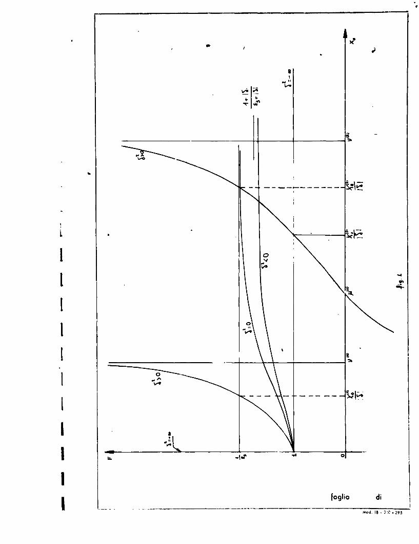
Here T" and F are always negative (sec fig. 2, 3) and
g,2 positive. The curves of fig. 1 are still valid in this
case'and show that an infinite ret of solutions exists.In the
frequency range this region corresponds to the conditions
< 1 W if vp <w and .if
When 0( approaches unity, Y, tends to zero and 1/,A.
1 to one of the values (d./\0
Tr e('- ' , - .-E
thwhere X0 is the m root of Jo
When 0 approaches infinity, rV tends t. zero
and the solution tends to one of the Xo poles of F2, namely
to (O where and (is
the m th root of the equation
loglio 8 di 19

S.p.A.
Consequently d. f o approaches zero.
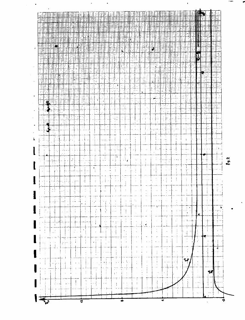
The behaviour of X0 is shown in fig. 4 for the special
case = - -2, -- 0.5, while in fig. 5 and 6 we have plotted
A(X, ,and P,rts versus d/A. ( Pand P being respectively.
the power flowing inside and outside the plasma).
The very unusual iharacteristics of this type of pro-
pagatlon are summarized below:
i) For each mode propagation can take place orily for
values of the OIAo ret'o between zero and a maximum
(&/A0)')(4/A0)€ which is characteristic of that mode.
2) For o given mode, whe d/AQ is between (t/A.o,
and (4A 0), propagation can take place with two different
ratios, but their group-velocities are opposite it,
s ign.
3) The axial flows of electromagnetic power in the air
and in the plasma have generally opposite diresetions. If PP;['a
we have an "average" forward wave, if p < an "average"
backward wave. The points lebeled "A" in fig. 5, where the group-
velocity is zero, correspond to the points "A" in fig. 6 where
pe-- , so that althougo some power is really flcwing sep-
arately in the air and in the plasma, the total average flow
is zero.
4)- The highest ratio PpIPa is obtained at
at this point the mth mode power ratio is:
(P~)eh 'K.(Lk) 4 h ,'v)
4) Propagation in the M < , , <'e,< o region
Here in the 0(; <0 range , is are negative
flF.7' and ' Is positive and smaller than unity fig. 8);
the behaviour of FI for the general cast E-.C.O Is shn
lr ig. C)d
Ioglo 9 di

S. p.A.
The curves indicate that iii tnis region only oine X, solution
may exist.-
When a approacies infinity, 'V tends to zero and the X,
solution of te dispersion equation tends to %; (5, ) if 014kl/e2
Tne parameter X0 increases wnen cA decreases and approacnes in-
finity at - , tne root of tne equation:
1'1- - when
Z9 __when .
S 9'
When Wzolfo tue X. solution crosses continuousl the c
abscissa and tends to Infinity in tne complex region.
Curves of IWI Ji, 1 are plotted in figs. 1r) to 1- tor tne spe-
cial case .,- -2, 6, = - 1.5, while the X. versus curve is
given In fig. 1-%
When I' IE,j tne curves snow clearly tnat no solution
exists ato(-o)tnen we do not expect any solution a!Lo at finite
values. 'lne propagatiok region is thus bounded by tne condi-
tion 6, .j .rI and becomes:I - o " 6, - I
In tite f'requency domain this corresponds to tne range:
W1 - V < S"' //i a -4W V
Wnit tne usual formulas tne s/A. and P/Pj versus d/) curves
can be calculated; they are plotted in figs. 14 and 11, for tne
case: = -2; 1 = 1 .f).
We snali finally note tuiat, as in tite previous case, the
power outsiae the plasma flows in a direction opposite
loglio 1 di

II!EI~U~~ S. p. A.
to that of power inside so that, being generally 0 <2 ,
the power flow in tkhe plasma is backward although the total
power is flowing forward.
BRILLOUIN DIAGRAM'JS
Keening 1. and 1 as constant pa-ameters in the Max-
well equations, it has been possible to solve the dispersion
equation with a straightforward procedure. BrilloUin dia-
S grams ( P' versus v ) are, instcad, more difficult to
derive because r, and Ej are functions of frequency.
In order to obtain from our computed data these dia-
grams, we have to solve the following system:
0 ~/ 0 (J/A 0 I E,,)(10) (
Let us keep constant the ratio oC -. and choose ail tne paire
of 6, and - values which satisfy the equation:
(1 ) ,=" ( ) (see fig.16)I. - ) .
The first two equations of the system (10) allows us to plot
in the 2?rd 1'A,:h4 versus 2,7d/Aga&C plene a set of curves, k .
being a constant for each curve. Let us find the intercepts
of these curves:
()L,
With the straight lines:
joglio 11 di "19

(13) CL i~,A
wnich represents tne tnird equation of the above system
(10), Krd being tne plasma density parameter wd d/
For given values of the frequency independent para-
meters a and KPd, these intercepts at different *,,values
plotted in the Kd versuspc plane provide the 3rillouin
diagrams:
(14) L1 (,k d
The computation nave been performed for two a values,
tue first being chosen in tiiecj region (a= 2.25), the second
in the < I region (a - 0.5). In figs. 17 to 20 we nave plotted
tae curves given'by tne equation (12) for the first X6 solutiods
and respectively for tne conditions I) a = 2.25, i'o;
II) a = 2.25, EJSo; III) a - 0.5, V) a - 0.5 it >, -
The BrIllouln diagrams, wnicn result from tuese and
similar curves for the second X, solutions, are plotted in
4- figs. 21 to 24.For eacn case three K d values nave been consi-
dered, namely: 1.5, 3.5, 10.
It is interesting to compare these curves with the corre-
spondling curves obtained by Could and Trivelpiece(3)and. by Smul-
lin and Corney(4)using the so-called quasi-static approximation.
These authors nave studied tue more general case of a circular
waveguide partially filled witu plasma; from tneir results tne
curves to be used in our case are easily derived by setting tne
waveguide diamete.r equal to infinity.
No significant difference is found in the benaviour of
tne Brillouln diagrams in tie w<L4 region (Kd( 4).
It this region all t,,e Kd versus (3dcurves start 1rom tue1oglio 1 2 di "

SS. p. A.
- origin and approacn asymptotically tne value Kp
or XoL, whichpver is smaller, except the first solution
mode which, when w. > , approaches the asymptotic value
A behaviour, slightly more complicated than predicted from
the quasi-static approximation, is found in the w-' wp
region. Here the curves start Irom different points Of thf
oL'=Pc line betwe, n dL -and V14, 'dJ dt and apnroach the
asymptotic value Kpl or d , whichever is larger. The sloi."
of these curves may be positive, neg:.tivc or partially po- *
sitive and partially ncgative, ,;o that t e wavoc can be
forward or backward. It Is worth t3 nuJIk that ir th- t,-*s;
st'.tl- Aproxtm.tion nil tries, wnvos aro .tw.ys ,y d.
The following details can be adPicd to the discussed
featireH in the A) ,w, region. The 3rillcuin diagrams start-
ing Points on the Kd 43L4 11nd jrf glv-n frcm th- simplo
rpl;.tlcn:
where: c = X0
Anothier simle refetion can be found, which allows
us to distinguish betwcen fgrward and backward wavps in
- the w V-'p region. LFt uo observ% the behaviour of
the ntercepts which RrovidethP -)rillouin diagrams, when
ib increases from zoro to unity and Kd varies consequently
from kd. to infinity. Fi,;.17 indicates clearly th:At, when
the intercept nointi f£al' in tie positive -, region, t.iere
i.; only one intprcelt for e.ch ED, value. In this case the
Kd versus /60 curve hs cvcrywhere a 2o:itive slope,
tite limit: pd--oo will be attained wnen Kd. Kb4, since it nas
to be considered Rs th e intercept with the , curve,
which is thlo only curve (1,') with an horizontal asymptot
I
logill 13 di '9

S. p. A.
A s.traitforward discussion tisen shows that all the inter-
cept points of a Brilloui curve shall fall in the posi-
tive C- region as far ao k is larger than this asym-
potic value , This is thus the condition for
forward waves and c.' be rewritten in, tne form:
When this condition is not satisfied, the waves may be
backward or start at low /3cL values as forward and change
to backward ai large /S values.
I--d-
1o9ho 1I 4 di . 9

S. p. A.
BIBLIOGRAI'H"
1)- A.I. Akhiezer at al.- Proc.U.N. Conference on the
Peaceful Uses of Atomic Energy
Vol.31, pp. 25 (Geneve, 1958)
2)- W.C. 'ichumann - .. Angew. Phys. 10 26(19bj)
3)- it.. Trivelpiece and R.W. Gould- J. Appl. Phys. 10
1764 (1959)
4)- L.U. '3wuilin and P. Chorney - liroc. Poly. inst. of
Brooklyn Symposiwm, April 1956
115Ioglio di
00
Of
loSod
Mo .18-21 . 9
Irj l1~ it~ iI ii jt t~ ~ fu l T I ; 4 71: 4 j~ 1!
17
I 4 4 J eq
-..
... ....
.... . ...-. ....
Li ...
... . 1.. ....
... ... ....
... .... . ...... ....-
.. ...I. .. .
.. ............ .. ... ..

- , . .........
................................ i ..
... .. .. ... .
.........
............... . ..

v ~ ~ ~ ~~~. ...... . ~4w. .-h
. ... .. ...
.. ... ............
.. ...... .
........
.. ... .I....
......... .
................
..... ..... .
. I ... .
..........................
I M4
..... ... ..
. . .. .. .. .....
.. .. .. .......... .

.. .. .......
* ....LA
I...... ...........
.. . .. . .. .

4-
.1 .. j..,I,
,
I . ,
I: ij. ~.
. ~1...........
~1 .
,
* . I
..
I' ~:1:1 ~1
I
..* 1
,
I , , . ,
.......
*
.., .
.
~. ~1
I........ .. ....................................
I, ~ 4I . . i. ,
I'
~ ,t ,.~
- J
- -~

.. ... .. .
..... ..
........
.....................................
4I ... ... ..
.........................
vI
1fogljo di
Mod. 18S 2W C 295

rJ
. . 'I .. ~.....
.. ~. *,,**~ Iii 1. ........... .
I...........................I ... ,...
. I.~ .
...............................
. , ~ V
. , . i t .
I. j
I . . .
. . . ................... S
I.......,...,..............II a
,,.., . . .
. I
I
. . . *
en 0

-i~ 'TI ]TF. Ti 42 ~'TTII.11'' I ~V KI.
;,.. 1 .. I-
I ..~ . .......... II I
.1.1.... I
I i~ I I .,
~ I ...I IC
II . i .4.
I.
4. .1 . - ., . -~.
.............................
.~: . .. .
V. ..
I...
S
U'
,..
I 0*4
I ~
....
I.....Ii:: II!~!
.1. I.i..;.I. I
K . . .. -
..............................
............................ I
'I I I *I. 1I: I
.1~
II I I ,.
I I
cD "4

t. :....
Ii I1 I I ... , 1~-
I . I
.... ~1..,.
.t.
I..............I I~1 - :.~ I
I I Ip ~ :1 I
...... i.... 1~ I 0
*..f ,I.: I ,, , .
.4 I........I
~m,. ~
U
*1
. .
. .
0
...~ *
I.
.1 ,. . .
I. . i
I I I
_____~
I I
~ -.,t-.--.-i..---.-i---..-. I Ig 0a

4-
*1 **~
I...
F ..7.....,.., .
.1 .. 2...................................................
.1... .- ~ -
.f, .. . .
I , . .. ~1.............I
S S I.
.......................... .............................................................. 3
I. I ,~. I
a I jI ...... S
h.I-
~.
. I
.I ....................................................... SI . . . . . .
~ I 1
.~ 0
I a,
bI .~. S
-.....
*'<
I V.7K..; *i. I. <1.. 2
B ~ '~ 1 ~jill
I~ Vt . . [';.................................I..........
~....i ~ ~..........
V..K-i-i*-~ I .K *1
-4-- - ~ -~-~-----~--- - -
'a 0

44.
... .. .. . . . ......
I . .... .
. . . . . ...........
S.. . . . . .. . . . . . . . . . . . .
- 41. ,
ca'

. . I ..
-. , ....i.
I .......................
*1~~~
I I
I I
I .ii
I .. I * .A. I
I I.
4. , . . ..
,.. I
* , . I
. ~4.
'a.
.. . 3. ,
.q .1-.. . .
j. . f... .II *I . I., .1
II ~
ii.~ II. ~
.1.. .
I. j~K ______ H __ i-KU
E~Ift~' 4 -. ~'4

47 4 4t+
... .. ....
I ~~~...............
I ~ - 'F . :
I iin
*INC
I It
It 1

1 'I.,1.1 I
..........................
.4 .I i .
* 11* I ii
* .* * 1* I ,
a~4* , 8
0
V.
.4.
4
4
o'4
-4
9.4
II 'S
* . a '~0
.4
. . ,....
. * .
I* *.*,....,
1.......................
* ... .. *
(.) 0- .,. -.4

. ... .. . .. . . . . . .I
I, , 0I.,r
I . .4

.1 I II . I
* ~.
***~ 'IF V...............................................~,.I * . ,.I ,
* , . , , . , 1
* . . . .~ ... ,
04
0C.'
a,('a
*
a
4'
a
IIIII
'1 - .4- .4-

I .. ..
* .
.1~1
. . 1~1 I
l:.~. .
I . II. .~
* . . I . I
S. I
I I *.........~1
*1* I I
0............................It ~I
~1
.9.a'
3
).... . ......
9
'9.
~.I ''-II ..............
.
t4II
-v '4 ,.

I. ~
............. i .... i..l. -~
., :1,
Ii . -~
I- * .1.1......................~
V . . . .0
~
0
I
-U

':~
ii
I I 2.
.I. .
.4* I ... ~.....
I.'.1.~. .......
...............
.1. .. ~.
........ K~'-. ~... .
..j .. ~ .:.I , I,.I.II I ~1'
. I
, .
.4.1~
4 . . . . . . .
... 4.
'1
. . ..
I
b
4 .
4-o *~-4

*1 ,,
........ ;... .
00

04
o A
I s oft~Ii i lli : i i
Ta
1,I i ilIi, i!f"" "3 4.I ID " U.
N. 0 . dog E- ** qga ,I I ~S 4
4 J " - b C b.4~. . ~ 303 k ~ C5~hR W2 £
"0°" "0ft 0IMo-I'1.-- -.. ., e@ r-e.9 .o
ll lii ! el ' -".l .
. . *. = !Iivuil-OU I" t -I R eu
!li~ii% alit
•.4r N .Alt
K O 1i1i g Il
U ~ ~ I~m x Ic Z a
rh. 05 41p.
I 3 c S... !! lo •SC - 0I II .,, 1. 0 5,40
I .t* i c * * -il I i.
ID~~o *45 C4 1 U(4 S C S3
-~~4 06 %1 S. ~'- ~ , * ~ 3C ~ a
a & 0 .b
° 6= °" c °'"E0 °
0 . I , ; c' i ' . *b U 0!1. U .. L " IS q
. , , . vK Ibi I
At c x "
ml '.- I I S.
OU4=~ ~ LI 0 04 Z1= -c- ,o . O)=: l
ol ILI ll2,i v
d9' lo "9 a- ..-,
va
I~~~~~~~l~~~ 0 4,3 0I toU . II l [- " I
498 d1c :
Recommended