Embed Size (px)
Citation preview

UNCLASSIFIED
^268 895 kif. the
ARMED SERVICES TECHNICAL INFORMAIS AGENCY ARLINGTON HALL STATION ARLINGTON 12, VIRGINIA
UNCLASSIFIED
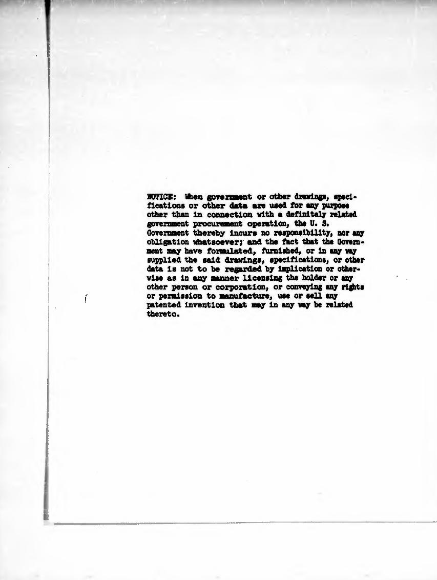
NOTICE: When flrnii iiiint or other drevlngs, speci¬ fications or other data are used for any purpose other than In connection with a definitely related government procuraient operation, the U. 8* Government thereby Incurs no responsibility, nor any obligation whatsoever; and the fact that the Qoven- ment nay have fonaulated, furnished, or In any say supplied the said drawings, specifications, or other data Is not to be regarded by lepllcation or other¬ wise sts In any Banner licensing the holder or any other person or corporation, or conveying any rights or permission to nanufacture, use or sell any patented Invention that nay In any way be related thereto.
k A CLOSED RESPIRATORY SYSTEM EVALUATOR
^ E. /. KUBIAK >r I REST ^ R. A. BAMBENEK C O
AMERICAN MACHINE b FOUNDRY COMPANY MECHANICS RESEARCH DIVISION
NILES 48, ILLINOIS
UFE SUPPORT SYSTEMS LABORATORY AEROSPACE MEDICAL LABORATORY
AERONAUTICAL SYSTEMS DIVISION
AIR FORCE SYSTEMS COMMAND
UNITED STATES AIR FORCE WRIGHT-PATTERSON AIR FORCE BASE, OHIO
- ’J i y>
NOTICES
When Government drawings, specifications, or other data are used for any purpose other than in connection with a definitely related Government procurement operation, the United States Government thereby incurs no responsibility nor any obligation whatsoever; and the fact that the Government may have formulated, furnished, or in any way supplied the said drawings, specifications, or other data, is not to be regarded by implication or otherwise as in any manner licensing the holder or any other person or corporation, or conveying any rights or permission to manufacture, use, or sell any patented invention that may in any way be related thereto.
Qualified requesters may obtain copies of this report from the Armed Services Technical Information Agency, (ASTIA), Arlington Hall Station, Arlington 12, Virginia.
This report has been released to the Office of Technical Services, U. S. Department of Commerce, Washington 25, D. C., for sale to the general public.
Copies of WADD Technical Reports and Technical Notes should not be returned to the Wright Air Development Division unless return is required by security considerations, contractual obligations, or notice on a specific document.

< B¡
e o
O (O
2*
i lili f!!?ii-¿ i ááaí®í3í<S0<
• • • • • -agg; >
u z o
l|illlii]*|i¡;
it'ii' milH! ¿ fc*^-aS • o ■“ o s sS252 i
! I
Û u E
u z D
1'1-2¾ si ! a¿S ■3
S¿ §- ^>■3 = w «
O ^ iiias |S5 «
¡Xph luilll itj i|i > b S « « 2 <2 lljllfi \UhP míM UliíÜ < • s a S 8 •
íiukmñí
s îlîâsifüilsl f 1
I I

SsiiSsiilsídü
M
S I
I 3
I
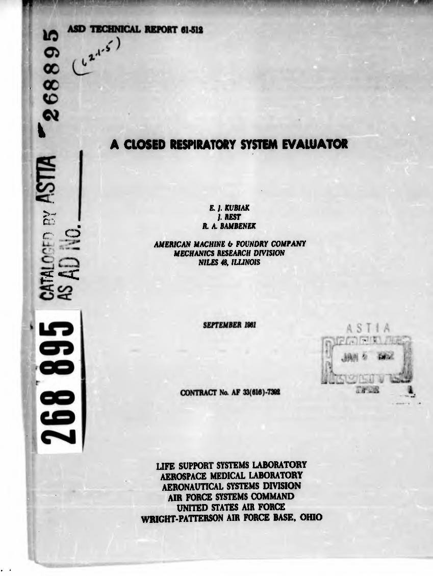
ASD TECHNICAL REPORT 61-512
A CLOSED RESPIRATORY SYSTEM EVALUATOR
£. /. KUBIAK I REST
R. A. BAMBENEK
AMERICAN MACHINE 0 FOUNDRY COMPANY MECHANICS RESEARCH DIVISION
NILES 48, ILLINOIS
SEPTEMBER 1961
CONTRACT MONITOR: C. C. ROACH
CONTRACT No. AF 33(616)-7392
PROJECT No. 6373
TASK No. 63120
LIFE SUPPORT SYSTEMS LABORATORY
AEROSPACE MEDICAL LABORATORY
AERONAUTICAL SYSTEMS DIVISION
AIR FORCE SYSTEMS COMMAND
UNITED STATES AIR FORCE WRICHT-PATTERSON AIR FORCE BASE, OHIO
900 - December 1961 - 12-474 6 475
yÇREWOKD
Ods report we prepared tgr the Mechanics Research Division of the faerican MachiM and Foundry Ccnpany, 7501 Hatches Aven», Hiles Ut, minois and sub- nitted to the Aerospace Medical Laboratory of the Aeronautical Systems Division under Contract IF 33(616)-7392, Project No. 6373, "Equipaient For life Support in Aerospace," and Teak No. ¿3120, "Respiratory Support Equipnent." This con¬ tract vas initiated ty »r. D. A. Keating and monitored by Mr. C. Q. Roach of the Respiratory Equipnent Section, Life &ipport Systems Laboratory, Aerospace Medical Laboratory.
V V, ^ dev®10P®8nt uorit reported herein was performed by ». E. J. öttiak of the Erstens Engineering Group, and Messrs. J. Rest and R. A. of the Applied Research Group at the Ibchanics Research Division. Ibis work vas started on 1 July I960 and completed on 31 May 1961. Ihe consultation afforded qy Hr. J. P. Marbarger, Aero Medical Laboratory, Ihiversity of Illinois Ifedieal School la greatly appreciated.
ii
ABSTRACT
A program to develop a device capable of simulating human respiration and re¬ cording the operating characteristics of closed respiratory systems is sumaarlted. The closed respiratory system evaluator as described is capable of performing ell tests necessary to evaluate the performance of any type closed respiratory system.
from an analysis of all conceivable techniques of simulating the respiration of manf va concluded that a mechanical system is superior to all others. Briefly y the operation of the evaluator entails the following: (l) oxygen is extracted from the gas flow along with any inert gases, carbon dioxide, and water vapor already present, (2) the inert gases unavoidably removed are added back to the flow from storage, (3) carbon dioxide and water vapor are added from storage in an amount equal to the desired addition rate plus that quantity unavoidably removed by oxygen extraction.
The desired values of the parameters of human respiration may be set indepen¬ dently of each other so that either realistic or unrealistic relationships can be chosen within certain limits. The capabilities of the evaluator are: (l) oxygen removal rate of 0.02 to 0.85 lb/hr at STP, (2) carbon dioxide addition rate of 0.02 to 2.8 lbs/hr, (3) sensible heat addition rate of 0 to 300 BTU/hr, and (4) water vapor addition rate of 0.02 to 0.9 lb/hr.
PUBLICATION REVIEW
Chief, Life Support Systems Laboratory Aerospace Medical Laboratory
iii
sarao*
1 INTRODUCTION
Background . i Syatra Requirements . 1 Approach . i
Cootmstion Spate* . 2 Absorption Spstsn . 2 Mechanical System . 2
2 MECHANICAL COMPONENTS . k Mixing Chanber . 4 Breather Platon . Ô Inlet and Outlet Valve . 8 Humidification System . 0 Extractor System . H Injection System . U Compensator System . U Metering . H Drive System .
3 AUTOMATIC CONTROL SISTEM .
Discussion . System Approach . Physical Description of Respiratory Evaluator Instrumentation and Controls .
Measuring Elements . Computing Elements . Control Elements .
APPENDIX A - OPERATING MANUAL . 30
17
a 19 19 19 26 28
iv

list or mwmmom naan wo, Pag
1 Evaluator Aasofely Soctlon Vlev 5
2 Evaluator Asaaribly Laft Bad View 6 3 Evaluator AsMably Right End Viov 7 k Inlet and Outlet Valva Assaribllas 9
5 float Assembly 10
6 Extractor and InJ actor Arrangement 12
7 Extractor Piéton and Compensator Assembly 13 8 Servo Driva System 1$
9 Breathing Machine Plow Diagram 18
10 System Control Scheme 20
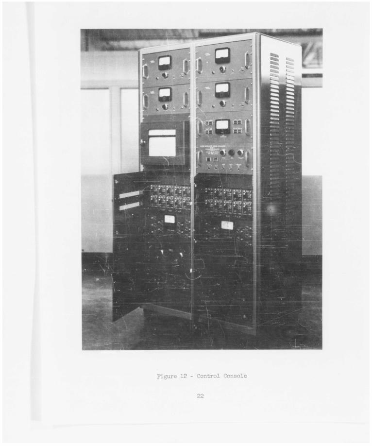
11 Control Console 21 12 Control Console 22
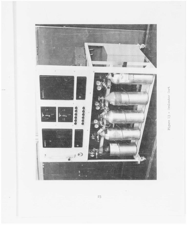
13 Evaluator Cart 23 1¾ Gas Stream Flow Diagram 25
15 Servo Multiplier 27
V
S3CTX0N 1
INTRODUCTION
Bac.< ground
Respiratory support systems must be tested for prolonged periods of time in order to obtain accurate data on system performance and relisbility. These tests can be hazardous to humar, subjects, especially with closed respiratory systems such as an algal gas exchanger or chemical reduction-electrolysis unit. An appa¬ ratus capable of simulating the respiratory processes of a human is, therefore, desirable to perfona complete evaluation of closed respiratory systems. This report stronarizes the results of the program to develop a closed respiratory system ¿valuator and to fabricate an engineering model of the approved design.
The features required by A3D for a closed respiratory system evaluator are briefly summarized for reference purposes.
1. The evaluator shall be designed for mounting exterior to an altitude chamber with a flanged opening for accommodating the connections necessary to simulate the breathing of a man in the chamber.
2. The evaluator shall simulate flow processes of the human breathing cycle by inhaling and exhaling 500 cc per cycle, which can be selected and maintained over the range of 10 to 50 cycles per minute.
3. Controls shall be provided to select and maintain an oxygen extrac¬ tion rate of 0.05 to 0.80 pounds per hour.
4. Controls shall be provided to select and maintain a carbon dioxide injection rate of 0.05 to 0.88 pounds per hour.
5. Controls shall be provided to select and maintain a vat-:'* vapor addition •/ate of 0.22 to O.90 pounds per hour.
6. Controls shall be provided to select and maintain a heat addition rate of 0 to 300 Btu's per hour.
7. Controls shall be provided to replace any inert gas (e.g., nitrogen) extracted along with oxygen.
6. Temperature, humidity, oxygen partial pressure, carbon dioxide partial pressure, total pressure, and volumetric flow rate of inlet and outlet gas streams shall be sensed, indicated and recorded.
9. Total pressure within the altitude chamber will be between 26o and 760 nin Hg.
1C. The evaluator shall be designed for continuous operation for periods up to 3° days.
Approach
The breathing of a man in a closed compartment can be simulated several dif¬ ferent ways. A qualitative evaluation of four approaches has indicated that a mechanical lung with automatically controlled injection and extraction rates is
1
]
superior to (l) a combustion system, (2) physical absorption processes, and (3) chemical absorption processes. The reasons for this selection are apparent fron the following descriptions and discussions.
Codbustlon System, ühe consumption of oxygen and production of carbon dioxide, water, and heat within the human body is termed metabolic combustion. Many differ¬ ent types of chemical reactions are Involved in the formation of these products; however, the following equation can be used to represent the stoichiometry of the net reaction.
where x, y and z refer to the number of carbon, hydrogen and oxygen atoms, respec¬ tively, in one molecule of nutrient. This net reaction can be simulated by combus¬ ting a mixture of fuels (e.g., acetylene, hydrogen, and methyl alcohol) with oxygen in a cooled or heated chamber. The rates of ojtygen consumption, carbon dioxide production, and water production could be varied by adjusting the flow rate of each constituent to the burner.
■ A combustion system is not considered to be a good approach for simulating the respiration of a man in a closed compartment for the following reasons:
1. The development of a burner capable of maintaining a stable flame over a wide range of mixture ratios and ambient pressures would require extensive research.
2. TO provide controls for independently varying the consumption of oxygen and production of carbon dioxide and water, the evaluator system would have to include an elaborate electronic computer for determining the variations required in reactant flow rates.
Absorption Systems. Oxygen can be removed from a gas stream by contact with a liquid which either physically absorbs oxygen into solution or absorbs and then reacts chemically with the oxygen. Both techniques can be made continuous by cir¬ culating the absorbent through the absorber and a regenerator. Control of oxygen removal rate could then be achieved by regulating absorbent flow rate and/or compo¬ sition. Chemical absorbents, however, would evaporate within the absorber and thus contaminate the gas stream; therefore, they are not advisable for use in the sub¬ ject evaluator. Physical absorption could be accomplished with water. However, to absorb 0.8 pounds of water per hour at room temperature requires a water circulation rate of about 1*0 gallons per minute. The size of the absorber and regenerator re¬ quired would be relatively large. Also, water will absorb carbon dioxide and inert gases. Since an absorption system requires the injection of carbon dioxide and inert gas, it has no advantage over a completely mechanical system for the subject evaluator.
Mechanical Systems. The main problem facing the development of the required evaluator is the selection and accurate control of oxygen consumption and carbon dioxide production rates (mass) over a wide range of pressures and simulated breathing rates. This could be attempted with critical flow orifices and pumps. Such systems, however, are difficult to calibrate and maintain in calibration. A more direct approach to this simulation problem is to sense and calculate the mass
2

now of each constituent in the inlet and outlet streams, compare the differences to selected values, and use an error signal to adjust the respective extraction and Injection flow rates. A system of this type has the following advantages.
1. Each control variable can be Independently operated.
2. Calibrations necessary are only for cocnaerclally available equipment whose performance is accurately known and for which suitable tech* niques have been developed.
3. The control system is conventional.
2|, Ko experimental research Is necessary to develop the system.
For these reasons, we decided at the beginning of this program to develop an automatically controlled mechanical system rather than a combustion or absorption system for simulating the respiration of a man in a closed compartment. The devel¬ opment of this system is described in the remainder of this report.

k\
%
SSCnON 2
MECHANICAL JCMFON3NTS
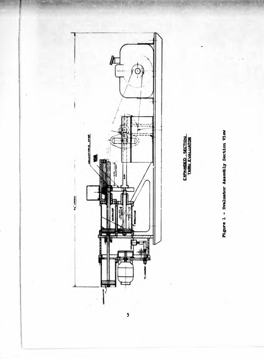
The main features of the evaluator are Illustrated in Figures 1, 2, and 3. The basic components are (l) a mixing chamber, which contains a circulating fan, resistance heating element, humidification system, and a breather piston, (2) extractor and injectors, and (3) a drive system. Gas is inhaled during the expan- sion stroke of the breather piston, and exhaled during the compression stoke. Oxygen consumption is simulated by the extractor which removes a portion of the gas from the mixing chamber during each stroke. Carbon dioxide production is simulated by injection. Since the extractor removes inert gases as veil as oxygen, an inert gas injector is necessary to replace that quantity of inert gas removed.
Mixing Chamber. The free volume of the mixing chamber was determined from consideration of the requirements that the machine shall have the capability of operating with the inlet port pressure from 2 to 70 mn Hg less than the total envi¬ ronment pressure and also have the capability of operating with the outlet port pressure from 3 to 100 ran Hg more than the total environment pressure.
The maximum positive pressure producible by the human lung is approximately 120 ran Hg. The chamber should be so designed that the compression stroke shall pro¬ duce this pressure. In equation form this is:
= PgVg (at constant temperature)
Patm ^chamber + Vdisplaced^ ” ^atm + 120^chamber
Thus: p
Vchamber I! 120 ^displaced ^ = Î5Ô ^00) = 3166 cc #
This volume was therefore selected for the mixing chamber.
Conversely, to calculate the negative pressure produced, the calculated mixing chamber of 3>l66 cc is closed off and the lung expanded 50G cc. Thus, we have:
Patm ^mixing ^ ~ ^Patm " P^Vmixing + Vdisplaced^ chamber chamber
.P .
■ -I05 mm Hg
This is in excess of the specification, which requires operation of the inlet at TO ran Hg less than ambient.
U
>
§ 4»
il CO
£
a a <
i
I S!
5

Figure 2 - Evaluator Assembly Left End View
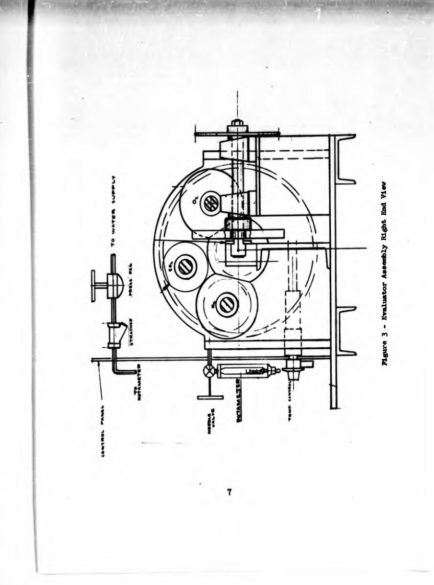
ligure 3 - Evaluator Assembly Right End View
The total volume of the miring chamber shown in the drawing is approximately 1*120 cc with water occupying 957 cc. The volume remaining is then approximately 3200 cc.
To secure compact design and efficient mixing of the gases, a cylindrical chamber design was selected« All internal parts of the chamber are aluminum or stainless steel to prevent corrosion.
The fact that the reservoir of water provided in the chamber for saturating the gases also affords a means of adjusting the free volume of the chamber should be noted. The water level can be changed by means of a float.
Breather Piston. To accomplish breathing in the mechanical lung, a piston is employed producing a fixed displacement of 500 cc.
Teflon piston cups are used to eliminate the need for lubrication. To secure a relatively low linear velocity of the cup for satisfactory performance, a 3-inch diameter piston was selected having a stroke of 1*.32 inches.
Inlet and Outlet Valves. The inlet and outlet valves are essentially check valves of the ball type. The valves are installed in a vertical position employing the weight of the ball for sealing. The seat of the check is coated with soft neo¬ prene rubber to insure proper closing of the valve. These valves are shown in Figure 1*.
In inhalation, the check is raised due to the lower pressure on the chamber side of the valve. In exhalation, the pressure increase in the chamber opens the check to the downstream side.
Humidification System. Distilled water from a five-gallon bottle is trans- ferred to the mixing chamber by means of a small diaphragm pump. The flow rate is indicated by a rotameter and regulated by means of a needle valve. With this arrangement, water can be added to the chamber at any rate between 0.02 and O.90 pounds per hour.
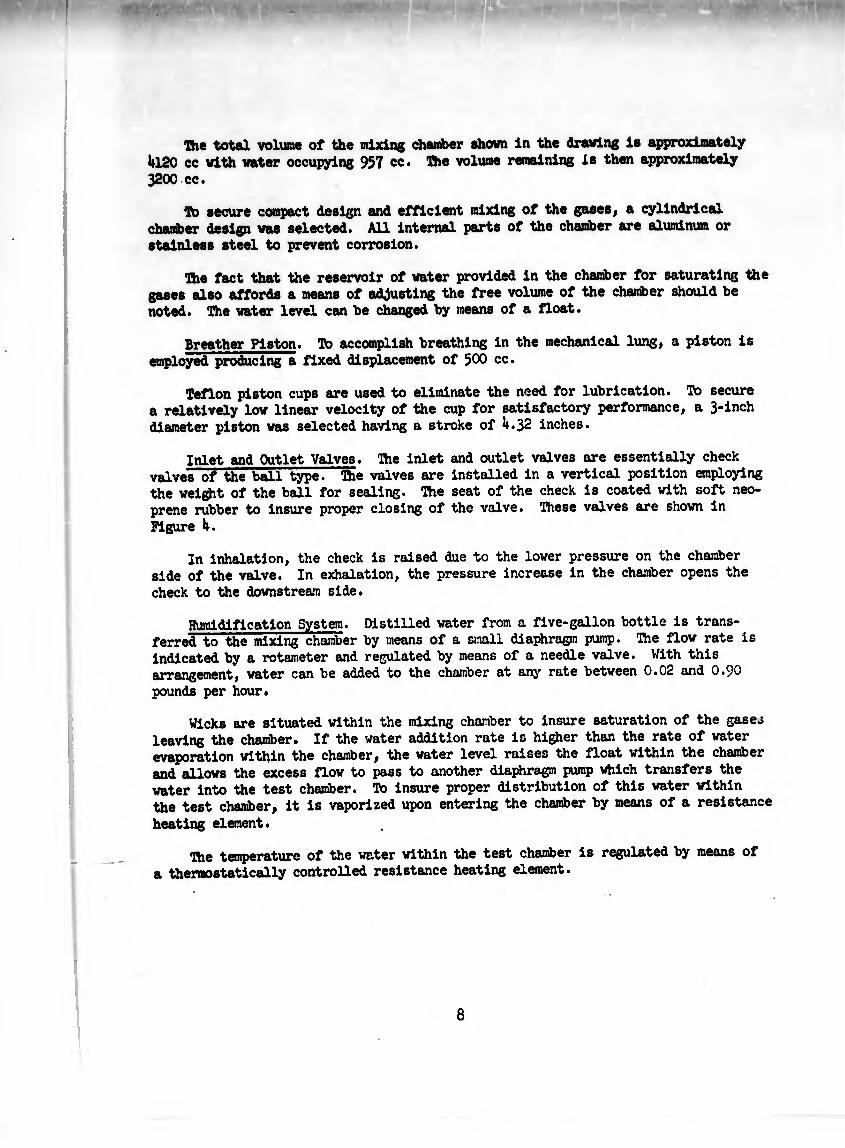
Wicks are situated within the mixing chamber to insure saturation of the gases leaving the chamber. If the water addition rate is higher than the rate of water evaporation within the chamber, the water level raises the float within the chamber and allows the excess flow to pass to another diaphragm pump which transfers the water into the test chamber. To insure proper distribution of this water within the test chamber, it is vaporized upon entering the chamber by means of a resistance
heating element.
The temperature of the water within the test chamber is regulated by means of a thermostatically controlled resistance heating element.
8

9
Figure U - Inlet and Outlet Valve Assemblies
10
Figure 5 * float Assembly
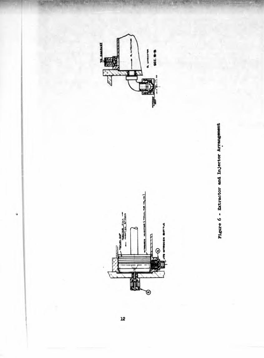
Extractor System. To extract oxygen fr« the evaluator, *_PW«P of identical design to the breather pump divert* a controlled amount of ga* from the chanfcer^ conSning the required amount of oxygen. Referring to Figure the inhalation pSTof the cycle, ga. i. extracted through the ^ail ^eck • tti* diverted gaa i* then exhausted externally through * spring-loaded check on the
exhalation part of the cycle.
Injection System*. Here again, the same type of pun® is used for injection of
CO- and Inert g» as is used in the breather pump. However, a ^^“^Les of^valving is required to accomplish filling of the pump and injection of «"S"68* Bottles of compressed nitrogen and carton dioxide are used as a source of supply and are closely regulated to either 10 or 15 P*ig.
As the piston of the injectors retract on the inhalation stroke, the spring- loaded8 check valve on the charter side must be set to 20 psig to ££«tany °f the gases from entering the charter on the fill stroke. On the injection part of ü£l., tta check oí the gM inlet .14» clo... and a. th. PT««». “ “ p818' the check to the charter opens and permits gas to enter. At the end of 8t¡™» îh! SÎmuw SthiHhe cylinder and charter is equaUted by holding the charter
StaulSneoualy, the inlrt ch«k «ly. fr» tha gw annrc. i. al» 1,,14 la place In order to preyent any leakage into the chamber which la now at a lover pressure level and open to the injector cylinder.
Aa seen in Figure 6, the injector piston has a canned surface which depresses « button and soring loads the check valve in the closed position. As the piston Ä ^a^e charter check valve «d the pressure i. thus equal¬
ised.
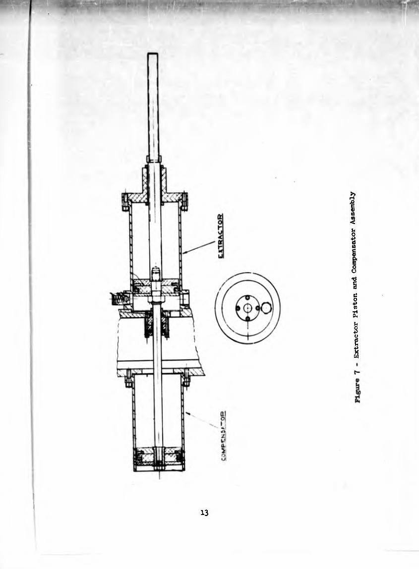
(Vuimansator System. With a constant reciprocating piston displacing 500 cc at in^nS^T^ see that in extraction., the breathing on intake vouldbe increased by the amount of gas extracted-- Also, “ * ^output would be increased by the addition of the injected inert gases.
To compensate for this variation, a pump of equal capacity is attachedin
tandem to°thepisto¿1 rod of the extractor. Whatever
CO and inwt gaa. The net result le that regardless of the quantity of gas ex- trlcted or injected pressure variations and flow rates are slnulated.
Figure 7 shows the construction of the extractor and compensator piston
assembly.
u*+«aT~(nff The volume of gasee extracted or injected is determined by the
Jiff’s ssr« carel» P« fart». » <* ^
at atmospheric pressure, these calculations are as follows*
11
12
Figure 6 - Extractor and Injector
13
Extractor Piston and Compensator Assembly
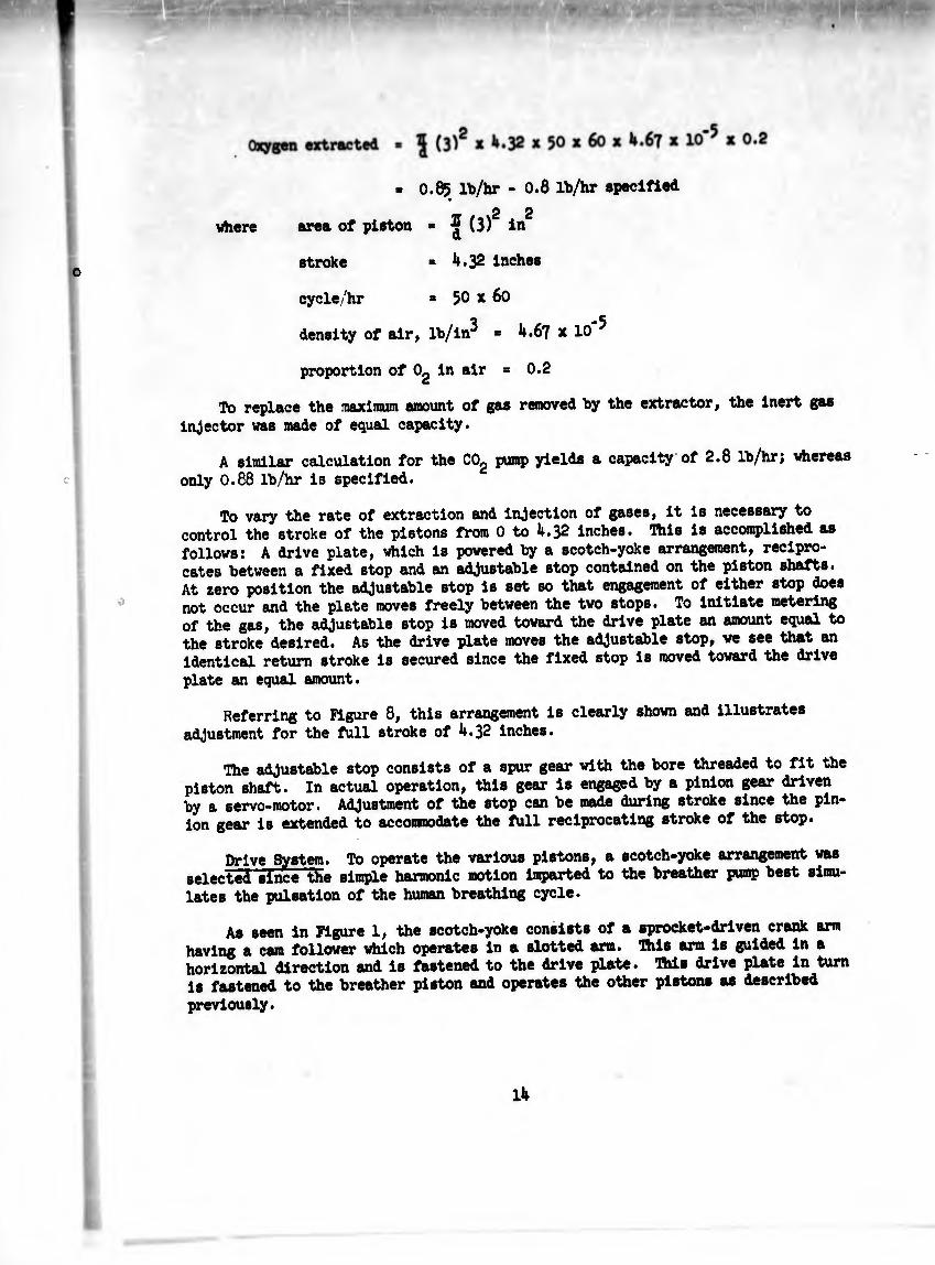
■ 0.85 lb/hr - 0.8 lb/hr specified
2 2 where area of piston - ^ (3) in
stroke » U.32 inches 0
cycle/hr * 50 x 60
density of air, lb/in^ = 4.6? x 10 ^
proportion of 0g in air = 0.2
To replace the niaximuin amount of gas removed by the extractor, the inert gas injector was made of equal capacity.
A similar calculation for the COg pump yields a capacity of 2.8 lb/hr; whereas only 0.88 lb/hr is specified.
To vary the rate of extraction and injection of gases, it is necessary to control the stroke of the pistons from 0 to 4.32 inches. Ihis is accomplished as follows: A drive plate, which is powered by a scotch-yoke arrangement, recipro¬ cates between a fixed stop and an adjustable stop contained on the piston shafts. At zero position the adjustable stop is set so that engagement of either stop does not occur and the plate moves freely between the two stops. To initiate metering of the gas, the adjustable stop is moved toward the drive plate an amount equal to the stroke desired. As the drive plate moves the adjustable stop, we see that an Identical return stroke is secured since the fixed stop is moved toward the drive plate an equal amount.
Referring to Figure 8, this arrangement is clearly shown and illustrates adjustment for the full stroke of 4.32 inches.
The adjustable stop consists of a spur gear with the bore threaded to fit the piston shaft. In actual operation, this gear is engaged by a pinion gear driven by a servo-motor. Adjustment of the stop can be made during stroke since the pin¬ ion gear is extended to accommodate the full reciprocating stroke of the stop.
Drive System. To operate the various pistons, a scotch-yoke arrangement was selected since the simple harmonic motion imparted to the breather pump best simu¬ lates the pulsation of the human breathing cycle.
As seen in Figure 1, the scotch-yoke consists of a sprocket-driven crank arm having a cam follower which operates in a slotted arm. This arm is guided in a horizontal direction and is fastened to the drive plate. This drive plate in turn is fastened to the breather piston and operates the other pistons as described
previously.
14

15
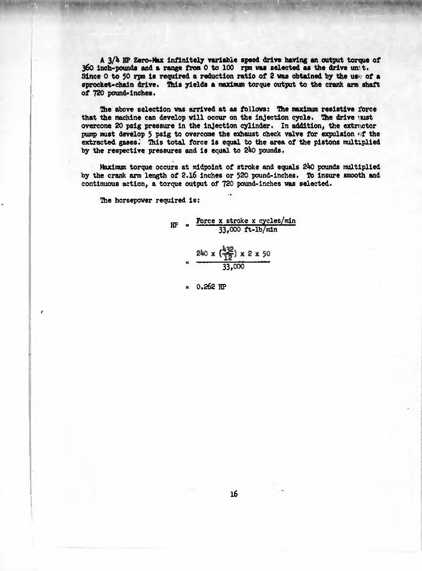
A 3/¼ HP Zero-Max infinitely variable speed drive having an output torque of 360 inch-pounds and a range from 0 to 100 rpo was selected as the drive vur t. Since 0 to 50 rpm is required a reduction ratio of 2 vas obtained by the us> of a sprocket-chain drive. This yields a maximum torque output to the crank arm shaft of 720 pound-Inches.
The above selection vas arrived at as follows: nie maximum resistive z'orce that the machine can develop vlll occur on the injection cycle. The drive ’ust overcome 20 psig pressure in the injection cylinder. In addition, the extmtor pump must develop 3 psig to overcome the exhaust check valve for expulsion >>t the extracted gases. This total force is equal bo the area of the pistons multiplied by the respective pressures and is equal to 2^-0 pounds.
Maximum torque occurs at midpoint of stroke and equals pounds multiplied by the crank arm length of 2.l6 inches or 520 pound-inches. To Insure smooth and continuous action, a torque output of 720 pound-inches vas selected.
••
Hie horsepower required is:
Force X stroke x cycles/min 33,000 ft-lb/min
33,000
0.262 HP

SECTION 3
AUTOMATIC CONTROL SYSTEM
Discussion
The mass flows of oxygen, carbon dioxide, and an inert gas at certain points in the evaluator are controlled automatically» It can be shown that the mass flow (m ) of a constituent of the mixture is given by
where Q is the volumetric flow rate of the mixture, p is the partial pressure of the constituent, Mr is the molecular weight of the constituent, R1 is a gas constant, and T is the temperature of the mixture
Applying this result to a mixture of gas consisting of Og, COg, HgO, Ng, we have,
RT
RT 2
as expressions for the mass flows of Og, COg, HgO, and Ng respectively. Therefore,
in order to measure the mass flow of any constituent (m.), it is first necessary to measure Q, p^, T and perform the computational operation indicated by,
M. QP1
“i ■
where M - is a constant for a given gas
After^the computation operation is accomplished, the signal generated is used for controlling purposes.
17
9y»t<n Approach
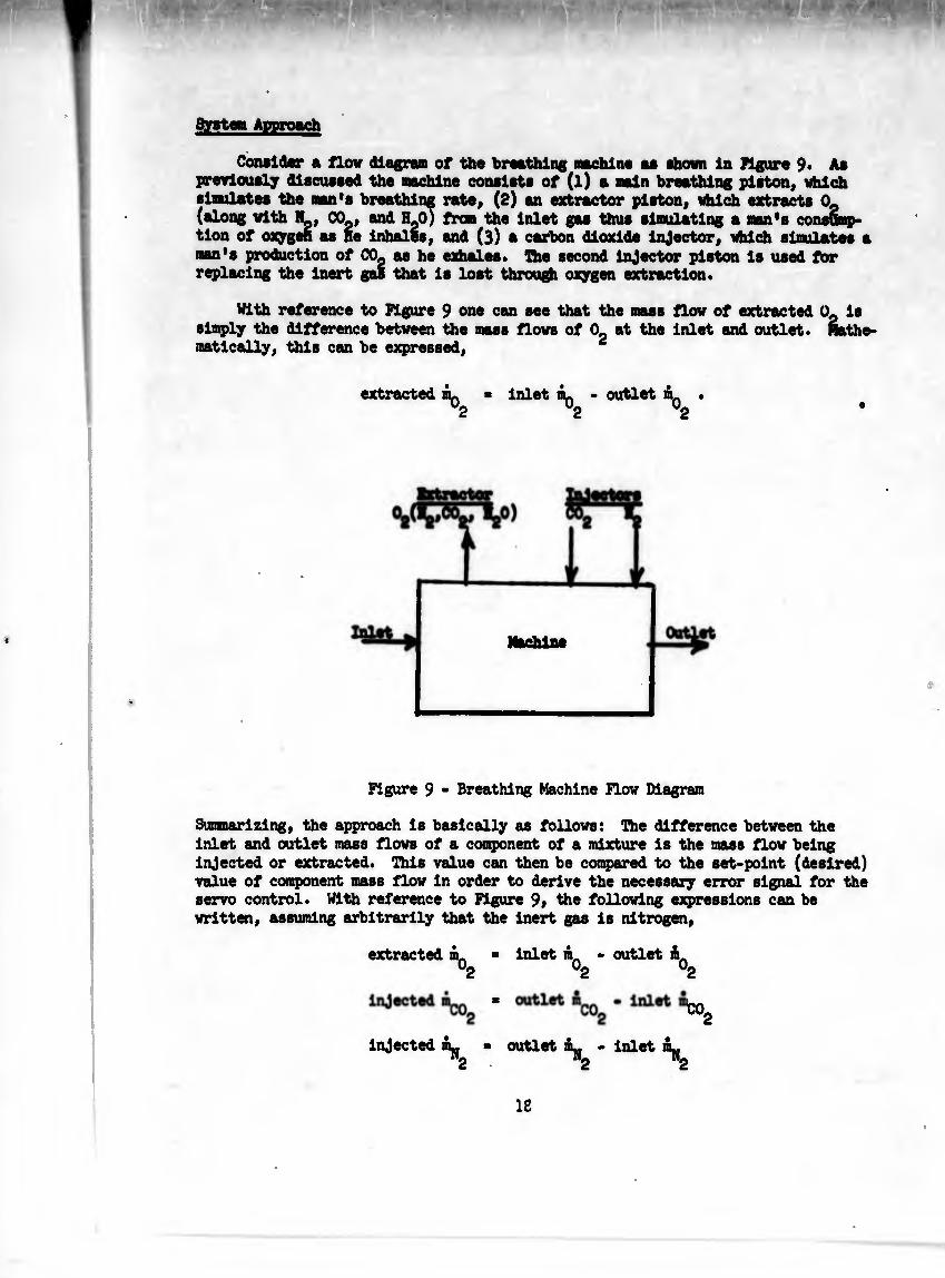
Consider a flow diagram of the breathing machine as shown In Figure 9. As previously discussed the machine consists of (l) a main breathing piston, which simulates the man's breathing rate, (2) an extractor piston, which extracts 0p (along with N_, CO , and H^O) from the inlet gas thus simulating a nan's consomp¬ tion of oxygen as He Inhales, and (3) a carbon dioxide Injector, which simulates a man's production of CO. M be exhales. The second Injector piston is used for replacing the Inert gas that is lost through oxygen extraction.
With reference to Figure 9 one can see that the mass flow of extracted 0. Is simply the difference between the mass flows of 0_ at the Inlet and outlet. Hathe- matically, this can be expressed, ¿
extracted « inlet ¿q - outlet mQ
Figure 9 - Breathing Machine flow Diagram
Summarizing, the approach la basically as follows: ühe difference between the inlet and outlet mass flows of a component of a mixture is the mass flow being injected or extracted. This value can then be compared to the set-point (desired) value of component mass flow In order to derive the necessary error signal for the servo control. With reference to Figure 9> the following expressions can be written, assuming arbitrarily that the inert gas is nitrogen,
extracted m. ■ inlet mn • outlet >2 02 02
W2
injected m^ « outlet . inlet m^ Injected
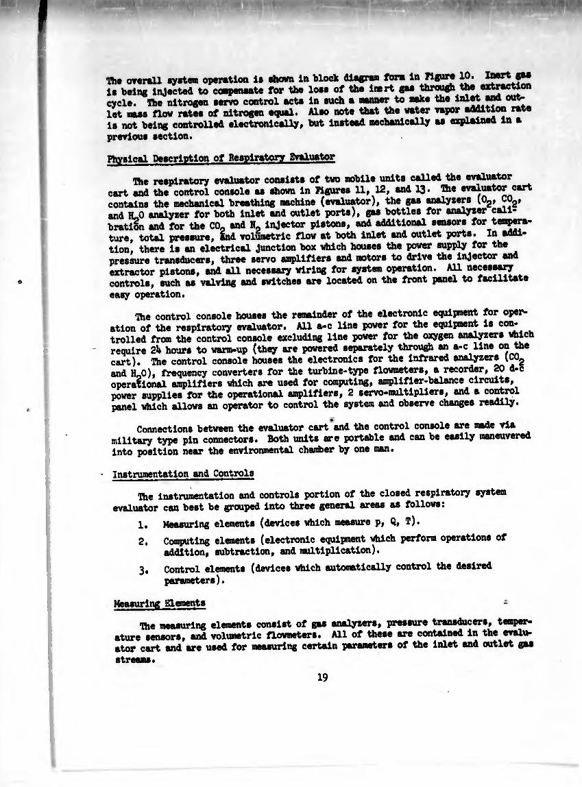
The overall syrtan operation le shown in block diagram form in Figure 10. I“®1* le being injected to compensate for the lose of the inert gas through the extraction cycle. The nitrogen servo control acts in such a manner to make the lnlJÍ let mass flow rates of nitrogen equal. Also note that the water vapor addition rate is not being controlled electronically, but instead mechanically as explained in a
previous section.
Physical Description of Respiratory Evaluator
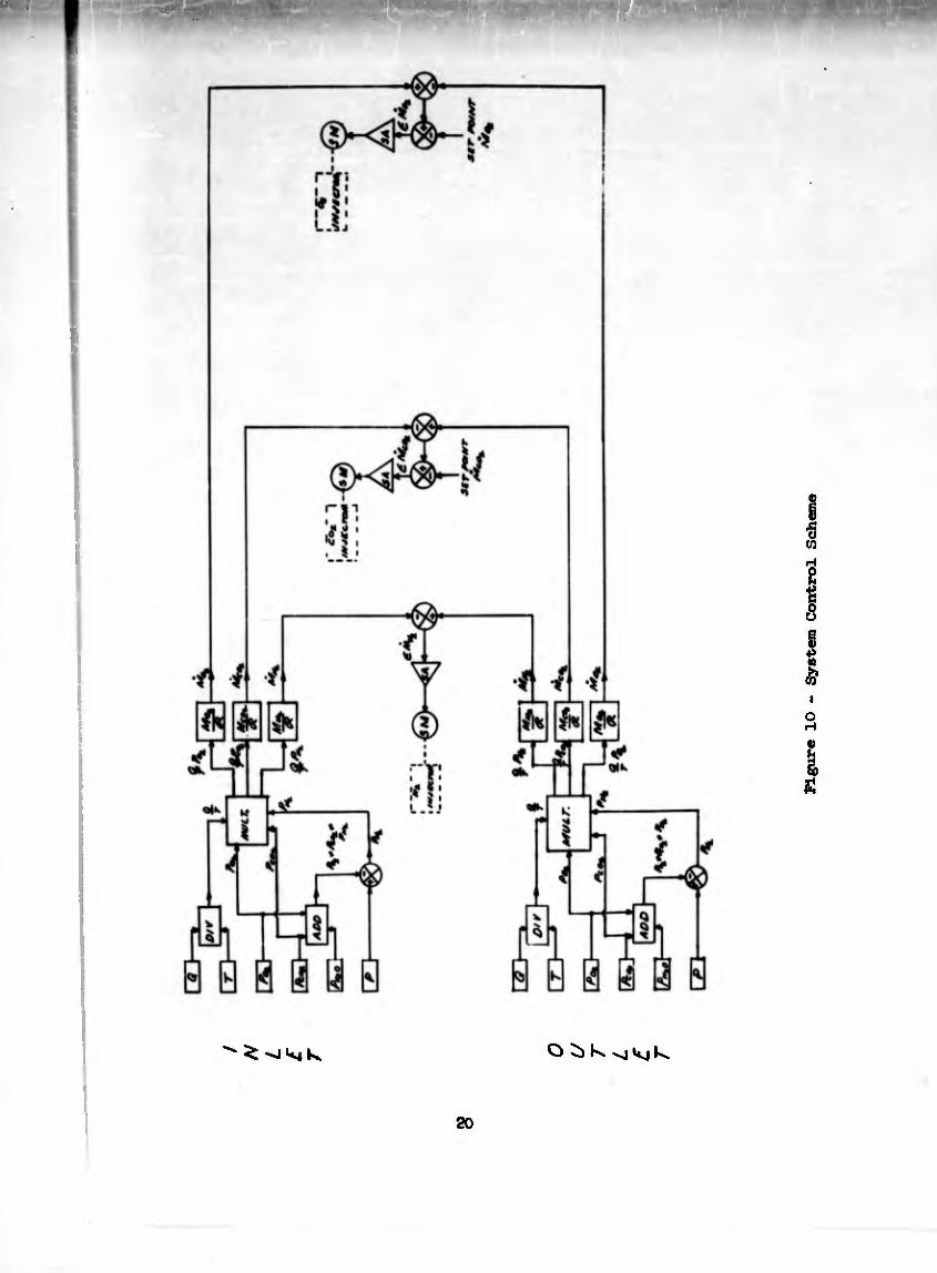
The respiratory evaluator consists of two mobile units called the evaluator cart and the control console as shown in Figures 11, 12, and 13. The evaluator cart contains the mechanical breathing machine (evaluator), the gas analyzers (Og, COg, and HoO analyzer for both inlet and outlet ports), gas bottles for analyzer cali¬ bration and for the C0o and N_ injector pistons, and additional sensors for tempera¬ ture, total pressure, and volumetric flow at both inlet and outlet ports. In addi¬ tion, there is an electrical Junction box which houses the power supply for the pressure transducers, three servo amplifiers and motors to drive the injector and extractor pistons, and all necessary wiring for system operation. All necessary controls, such as valving and switches are located on the front panel to facilitate
easy operation.
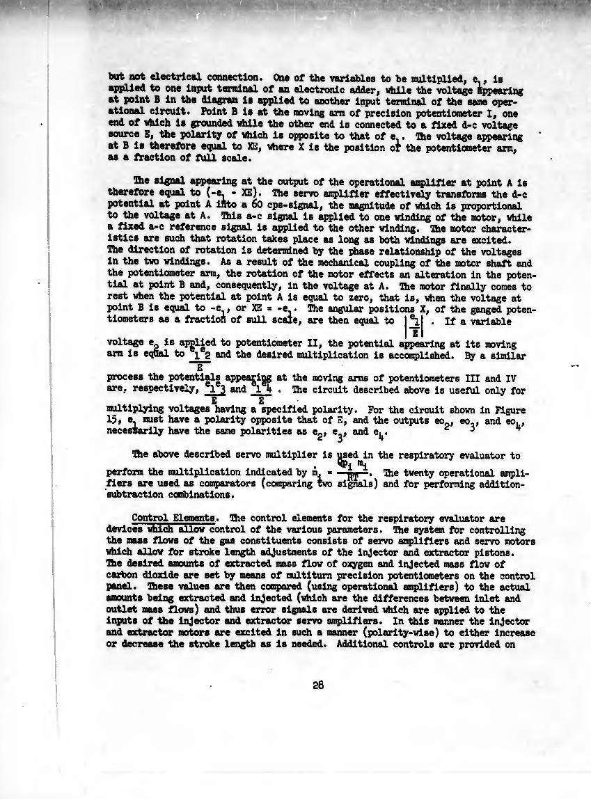
The control console houses the remainder of the electronic equipment for oper¬ ation of the respiratory evaluator. All a-c line power for the equipment is con- trolled from the control console excluding line power for the oxygen analyzers which require 2h hours to warm-up (they are powered separately through an a-c line °n th* cart). The control console houses the electronics for the infrared analyzers (COg and HqO), frequency converters for the turbine-type flowmeters, a recorder, 20 d-c operational amplifiers which are used for computing, amplifier-balance circuits, power supplies for the operational amplifiers, 2 servo-multipliers, and a control panel which allows an operator to control the system and observe changes readily.
Connections between the evaluator cart and the control console are made via military type pin connectors. Both units are portable and can be easily maneuvered into position near the environmental chamber by one man.
• Instrumentation and Controls
The instrumentation and controls portion of the closed respiratory system evaluator can best be grouped into three general areas as follows:
1. Measuring elements (devices which measure p, Q, T).
2. Computing elements (electronic equipment which perform operations of addition, subtraction, and multiplication).
3. Control elements (devices which automatically control the desired parameters).
Measuring Elements *
The measuring elements consist of gas analyzers, pressure transducers, temper¬ ature sensors, and volumetric flowmeters. All of these are contained in the evalu¬ ator cart and are used for measuring certain parameters of the inlet and outlet gas
streams.
19
O K vHíj k*
20
Figure 10 - System Control Scheme
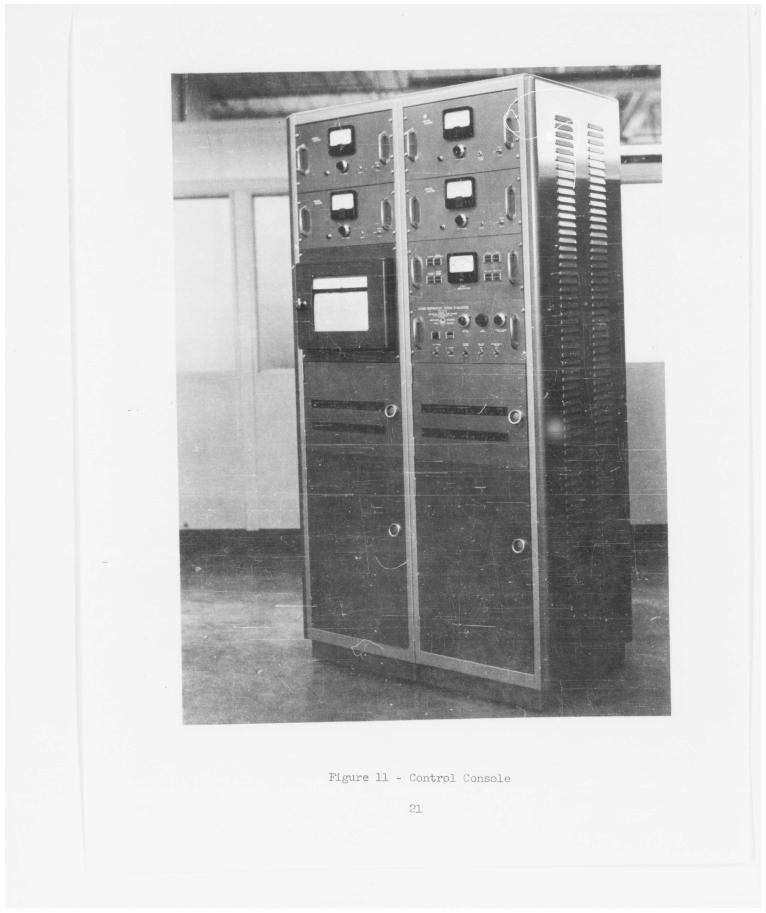
Figure 11 - Control Console
21
MiM
Figure 12 - Control Console
Ioo-pc3:3d>
OOiH
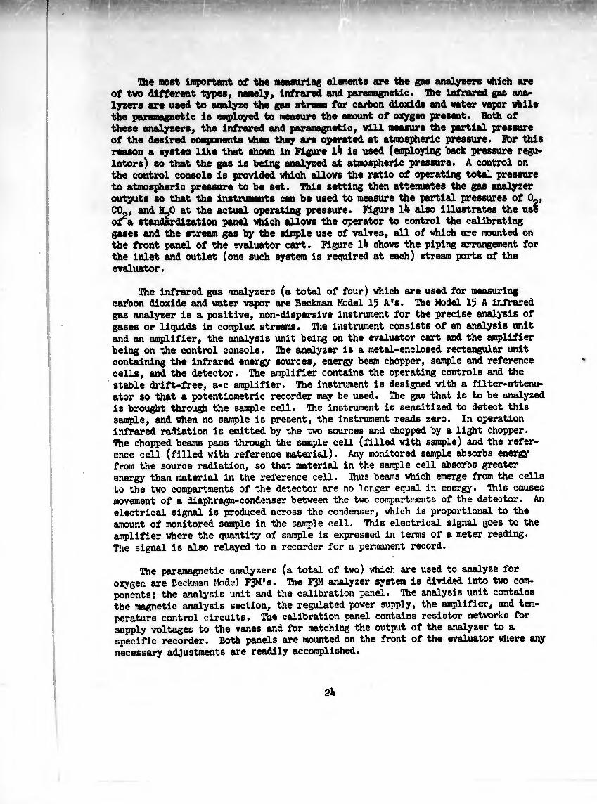
The most Important of the measuring elements are the gas analyzers vhich are of two different types, namely, infrared and paramagnetic. The Infrared gas ana¬ lyzers are used to analyze the gas stream for carbon dioxide and water vapor while the paramagnetic is employed to measure the amount of oxygen present. Both of these analyzers, the Infrared and paramagnetic, will measure the partial pressure of the desired components when they are operated at atmospheric pressure. Far this reason a system like that shown in Figure l4 is used (employing back pressure regu¬ lators) so that the gas is being analyzed at atmospheric pressure. A control on the control console is provided which allows the ratio of operating total pressure to atmospheric pressure to be set. This setting then attenuates the gas analyzer outputs so that the instruments can be used to measure the partial pressures of Og, COp, and HpO at the actual operating pressure. Figure l4 also Illustrates the use or a standardization panel which allows the operator to control the calibrating gases and the stream gas by the simple use of valves, all of which are mounted on the front panel of the evaluator cart. Figure l4 shows the piping arrangement for the inlet and outlet (one such system is required at each) stream ports of the evaluator.
The infrared gets analyzers (a total of four) which are used for measuring carbon dioxide and water vapor are Beckman Model 15 A's. The Model 15 A infrared gas analyzer is a positive, non-dispersive instrument for the precise analysis of gases or liquids in complex streams, ftie instrument consists of an analysis unit and an amplifier, the analysis unit being on the evaluator cart and the amplifier being on the control console. The analyzer is a metal-enclosed rectangular unit containing the infrared energy sources, energy beam chopper, sample and reference cells, and the detector. The amplifier contains the operating controls and the stable drift-free, a-c amplifier. The instrument is designed with a filter-attenu¬ ator so that a potentiometric recorder may be used. The gas that is to be analyzed is brought through the sample cell. The instrument is sensitized to detect this sample, and when no sample is present, the instrument reads zero. In operation infrared radiation is emitted by the two sources and chopped by a light chopper. The chopped beams pass through the sample cell (filled with sample) and the refer¬ ence cell (filled with reference material). Any monitored sample absorbs energy from the source radiation, so that material in the sample cell absorbs greater energy than material in the reference cell. Thus beams which emerge from the cells to the two compartments of the detector are no longer equal in energy. This causes movement of a diaphragm-condenser between the two compartments of the detector. An electrical signal is produced across the condenser, which is proportional to the amount of monitored sample in the sample cell. This electrical signal goes to the amplifier where the quantity of sample is expressed in terms of a meter reading. The signal is also relayed to a recorder for a permanent record.
The paramagnetic analyzers (a total of two) which are used to analyze for oxygen are Beckman Mode] FJM's. The F3M analyzer system is divided into two com¬ ponents; the analysis unit and the calibration panel. The analysis unit contains the magnetic analysis section, the regulated power supply, the amplifier, and tem¬ perature control circuits. The calibration panel contains resistor networks for supply voltages to the vanes and for matching the output of the analyzer to a specific recorder. Both panels are mounted on the front of the evaluator where any necessary adjustments are readily accomplished.
2h
i w
!
25
The Model F3M measures the paramagnetic properties of the sample gas and thus Its oxygen content due to the fact that oxygen Is highly magnetic. Most cotanon gases are only slightly affected by a magnetic field. The magnetic property of oxygen is so pronounced that it is possible to determine a few parts per million of oxygen in a gas mixture.
The total pressure of the gas mixture is measured by a CEC Type 1*-312A pressure pickup having a full range of 15 psla (absolute). Unbonded straingage windings con¬ nected in a four-arm bridge comprise the sensing elements of the variable-resistance- type transducer. Pressure against the diaphragm produce a displacement of the sen¬ sing element, changing the resistance of the active arms and causing an electrical output precisely proportional to the applied pressure. Acceleration and vibration have little net effect on bridge output, as they are cancelled by the geometry and winding arrangement of the star-spring-type sensing element. Compensation against the effects of wide ambient-temperature variation is provided by location of the two inactive arms in close proximity to the active windings, and through careful selection of the materials used in the painstaking manufacture of these pickups.
The device used to measure the volumetric flow of the inlet and outlet gas streams is a Potter Aeronautical flow sensing element which consists of a turbine- type flowmeter and an electronic frequency converter which converts the frequency output of the flowmeter into a d-c millivolt output. The Potter turbine flowmeter incorporates a high efficiency rotor which spins freely within a venturi and consists of a housing designed to adapt directly into the piping through which the fluid to be measured is flowing. A hydraulically self-positioned rotor is suspended within the housing. Within the rotor of the flowmeter is a small 2 or 4 pole permanent magnet. As fluid flows through the pipe, the rotor revolves at a speed determined by the velocity of the fluid passing the rotor blades and the blade angle. Mounted on the outside of the housing is a pick-up cell, so placed that the rotation of the rotor and permanent Alnlco magnet causes an a-c voltage to be induced in it. The frequency of this voltage is equal to the speed of rotor or twice the speed of the rotor depending upon the number of poles. This a-c voltage is conducted to various types of instrumentation through a shield cable. Since the turbine-flow¬ meter is a frequency device (that is, frequency of output signal is proportional to flow) a frequency converter is needed. A model 3C-1 Potter Frequency Converter is used which enables the output signal to then be recorded and/or used for control¬ ling. The flowmeters are on the evaluator cart and the frequency converter is in the control console.
The last measuring element to be discussed is the temperature sensor. Four sensors are actually used - a thermocouple and resistance bulb at each of the two ports. The thermocouple which is a copper-constantan is used for recording purposes only. The resistance bulb is used for computing circuitry which will be discussed next.
Computing Elements. The computing elements of the respiratory evaluator are basically d-c operational amplifiers which perform addition-subtraction operation and 2 servo-multipliers which perform multiplication. Twenty operation amplifiers are used, ten for inlet stream calculations and ten for outlet stream calculations. Each set of ten amplifiers is housed in a manifold manufactured by G. A. Phllbrlck
26
(Model K7-A10). The Phllbrick Model K7-A10 le a precision inetruaent of usual versatility. With the addition of appropriate external circuitry, a vide variety of instrument or computing configurations can be set up quickly and yet with remarkable economy • As a lov-coat computing instrument p it offers unusual flexi- billty as an analog "simulator" of large-scale systems or as a package of 10 un¬ committed amplifiers to extend computer facilities. The K7-A10 is also veil suit as a piece of industrial or production-line test equipment where stabilized, high- reliability amplifiers are required in a convenient bench-top or rock-mounted chas¬ sis. The chopper-stabilized vide-band d-c USA-3 amplifiers incorporated in the manifold are responsible for the remarkable versatility of K7-A10. It can be used at all computing speeds, from "real time" or even "slow time to the fastest repet¬ itive speeds. Operating periods from milliseconds to hours are feasible, depending only on the computing capacitors employed and on the type of stimulation. Signals supplied may be sinusoidal (0.01 up to 50 KC), step-vise, random, or in any combin¬ ation. Operation may be repetitive or "single-shot". The K7-A10 is powered by a well regulated power supply such m the Philbrick Model R-300. The R-3°0 consists of two regulated power supplies on one chassis, slaved to a common reference. They furnish plus and minus 300 v d-c, each rated at 300 ma. The supply also provides strai^it-through a-c power, fused and switched at the main power switch, at each of
the two output connectors.
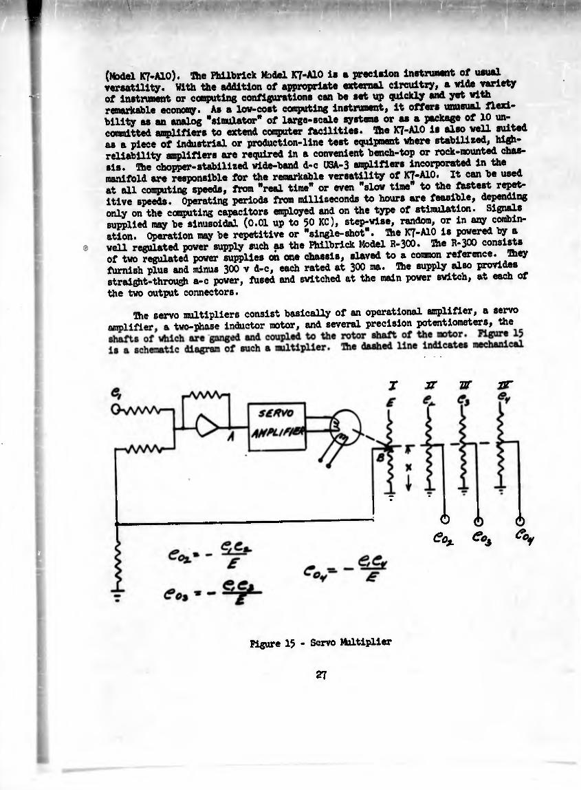
The servo multipliers consist basically of an operational amplifier, a servo pumUfMer. «. twn-Tjhase inductor motor, and several precision potentiometers, the
J JT ZT 2T
Ô è 6 £ox e°i
Figure 15 - Servo Multiplier
27
tout not electrical connection. One of the variables to be multiplied, e., la applied to one input terminal of an electronic adder, while the voltage appearing at point B in the diagram is applied to another input terminal of the same oper¬ ational circuit. Point B is at the moving arm of precision potentiometer I, one end of which is grounded while the other end is connected to a fixed d-c voltage source E, the polarity of which is opposite to that of e.. The voltage appearing at B is therefore equal to XE, where X is the position of the potentiometer arm, as a fraction of full scale.
Ihe signal appearing at the output of the operational amplifier at point A is therefore equal to (-e^ - XE). The servo amplifier effectively transforms the d-c potential at point A into a 6o cps-signal, the magnitude of which is proportional to the voltage at A. This a-c signal is applied to one winding of the motor, while a fixed a-c reference signal is applied to the other winding. The motor character¬ istics are such that rotation takes place as long as tooth windings are excited. Ihe direction of rotation is determined toy the phase relationship of the voltages in the two windings. As a result of the mechanical coupling of the motor shaft and the potentiometer arm, the rotation of the motor effects an alteration in the poten¬ tial at point B and, consequently, in the voltage at A. The motor finally comes to rest when the potential at point A is equal to zero, that is, when the voltage at
The angular positions X, of the ganged poten- 4 0 *
point B is equal to ~e., or XE = -e.• The angular posit tiometers as a fraction of sull scale, are then equal to If a variable
voltage e. is applied to potentiometer II, the potential appearing at its moving arm is equal to 3/2 and the desired multiplication is accomplished. By a similar
E process the potentials appea^igg at the moving arms of potentiometers III and IV are, respectively, 1 3 and 1 h . The circuit described above is useful only for
E £ multiplying voltages having a specified polarity. For the circuit shown in Figure 15# e. must have a polarity opposite that of E, and the outputs eop, eo_, and eo., necessarily have the same polarities as e2, e , and e^. 234
The above described servo multiplier is ^sed in the respiratory evaluator to
perform the multiplication indicated by m. = —The twenty operational ampli¬ fiers are used as comparators (comparing two signals) and for performing addition- subtraction combinations.
Control Elements. The control elements for the respiratory evaluator are devices which allow control of the various parameters. The system for controlling the mass flows of the gas constituents consists of servo amplifiers and servo motors which allow for stroke length adjustments of the injector and extractor pistons. The desired amounts of extracted mass flow of oxygen and injected mass flow of carbon dioxide are set by means of multlturn precision potentiometers on the control panel. These values are then compared (using operational amplifiers) to the actual amounts toeing extracted and injected (which are the differences between inlet and outlet mass flows) and thus error signals are derived which are applied to the inputs of the injector and extractor servo amplifiers. In this manner the injector and extractor motors are excited in such a manner (polarity-wise) to either increase or decrease the stroke length as is needed. Additional controls are provided on
28

tb. control ponel (control conçol.) »blch nUoo tb. °p.rntor to «t tlon mt. »d al» control «rlonçcy.t» ^ milctor light. and Infrared chopper motors. In Mam power control is so designed
mérito pSto Äo^iT-ip r tor the neceswry c^t without requiring the entire system to be in operation.
29

AFFEKDIX A
OPERATING MANUAL

IHTRODUCTIOW
The Closed Respiratory System Evaluator Is an electro-mechanical system designed to accurately perform the precision metering of gases over long periods of time. Be¬ cause of the many operations performed, the system Is Inherently complex. The operator of this machine must therefore be thoroughly familiar with the principles of operation and operational procedures if satisfactory performance Is to be obtained. It Is therefore necessary that the operator should have read the final engineering report, this operating manual and the »"»rnini « supplied by the manufacturers of the major components. The supplied manufacturer's manuals that should be read are:
1. Beckman Model 15A Infrared Analyzer
2. Beckman Model F3 Oxygen Analyzer
3- Potter Model 3C-1 Frequency Converter and Flowmeter Calibration Curves
4. Fhilbrlck Model R-300 Compound Regulated Dual Power Supply
Philbrick Model K7-A10 Stabilized Operational Manifold
6. Daystrom-Weston Model 6702 Multiple Station Recorder
It is important to note that there are four Beckman Model 15A Infrared Analyzer Manuals, one for each of the four infrared analyzers supplied with the system. These manuals are identical except for the calibration data on the last page in each manual. DO NOT lose this data because it is necessary for accurate calibration of the analyzers. The calibration data sheets, the analysis units, and the amplifier units are all labeled (such as inlet CO« or outlet H«o). Similarly, other instrumentation which is duplicated at the inlet and outlet stream ports is also suitably marked.
WARM-UP OPERATION
The electrical power required for the system is 115 volts, 60 cps, single phase, and is carried through two separate line cords, one for the evaluator cart and the other for the control console. The line cord to the evaluator cart carries power for (l) the oxygen analyzers, (2) the drive motor, (3) the sampling pumps, and (4) the excess water pump. The infrared analyzers obtain their power from the control console. Switches are provided on the cart for energizing each of these components, except for the oxygen analyzers which are energized as soon as the cart line cord is plugged into a power outlet. This arrangement prevents the accidental shut-off of the oxygen analyzers during the "warm-up" period.
All the equipment on the control console is switch controlled from the front side of the console. All power switches on purchased components, such as power supplies and amplifiers, have been Jumpered to prevent their misuse. Figures l6 and 17 are sketches of the console and the cart showing the location of the components.
In order to prepare the system for operation the following warm-up procedure should be used.
A. At least twenty-four (24) hours before a test is to be made:
30
Figure l6 - SKETCH OF CONTROL CONSOLE
31
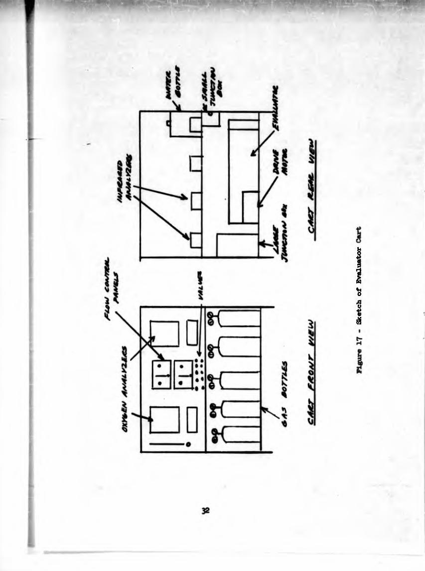
Sketch of Evaluator
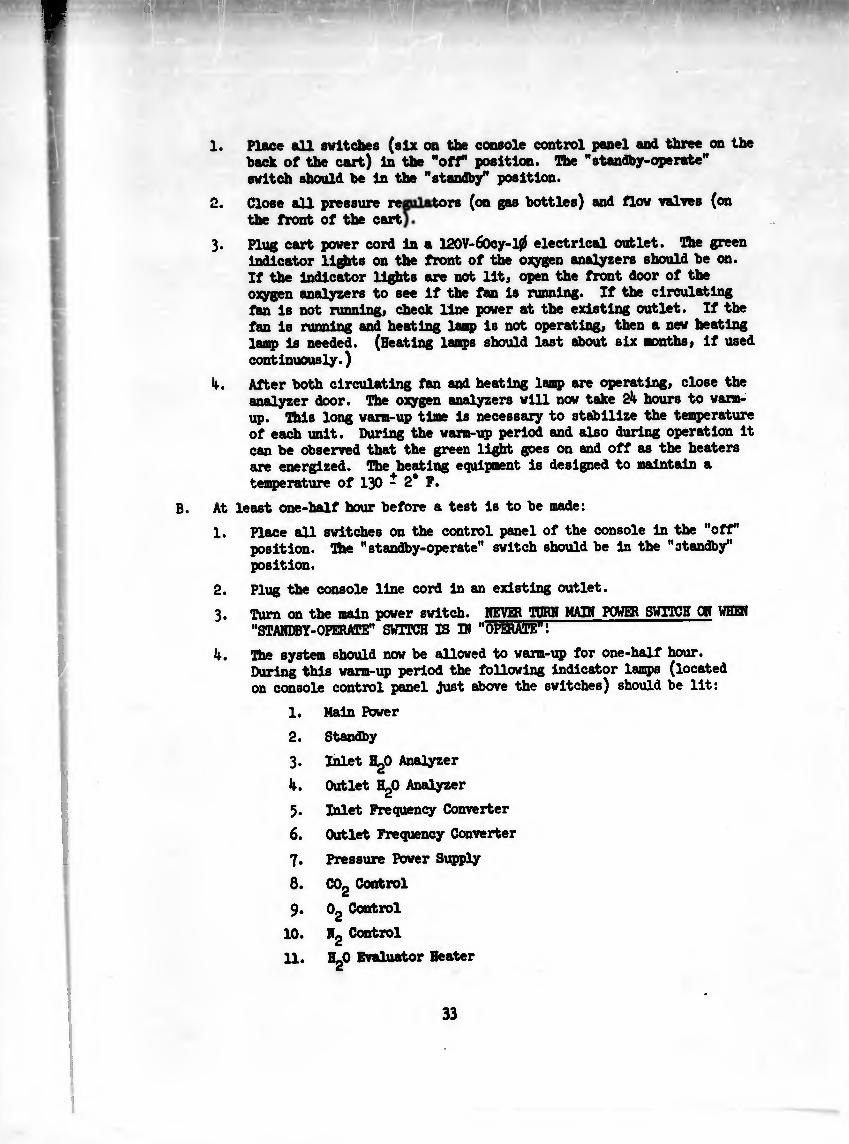
1. Place all switches (six on the console control panel and three on the back of the cart) In the "off position. The "standby-operate" switch should be in the "standby” position.
2. Close all pressure re tors (on gas bottles) and flow valves (on the front of the cart
3. Plug cart power cord in a 12OV-6Ocy-10 electrical outlet. Hie green indicator lights on the front of the oxygen analyzers should be on. If the indicator lights are not lit; open the front door of the oxygen analyzers to see if the fan is running. If the circulating fan is not running, check Une power at the existing outlet. If the fan is running and heating laap is not operating, then a new heating Tump is needed. (Beating lamps should last about six months, if used continuously.)
4. After both circulating fan and heating lamp are operating, close the analyzer door. The oxygen analyzers will now take 2k hours to warm* up. 'I'M « long warm-up time is necessary to stabilize the temperature of each unit. During the warm-up period and also during operation it can be observed that the green light goes on and off as the heaters are energized. The heating equipment is designed to maintain a temperature of I30 - 2* P.
At least one-half hour before a test is to be made:
1. Place all switches on the control panel of the console in the "off' position. The "standby-operate" switch should be in the "standby" position.
2. Plug the console line cord in an existing outlet.
3. Turn on the mM" power switch. rihVJflt TORN MAIM POWER SWITCH OM UHEH "STANDBY-OPERATE" SWITCH IS IN "OPERATE*Í ~
4. The system should now be allowed to varm-up for one-half hour. During this warm-up period the following indicator lamps (located on console control panel Just above the switches) should be lit:
1. Main Power
2. Standby
3. Inlet HgO Analyzer
k. Outlet HgO Analyzer
5. Inlet Frequency Converter
6. Outlet Frequency Converter
7. Pressure Power Supply
8. COg Control
9. Og Control
10. Mg Control
11. HgO Evaluator Beater
33
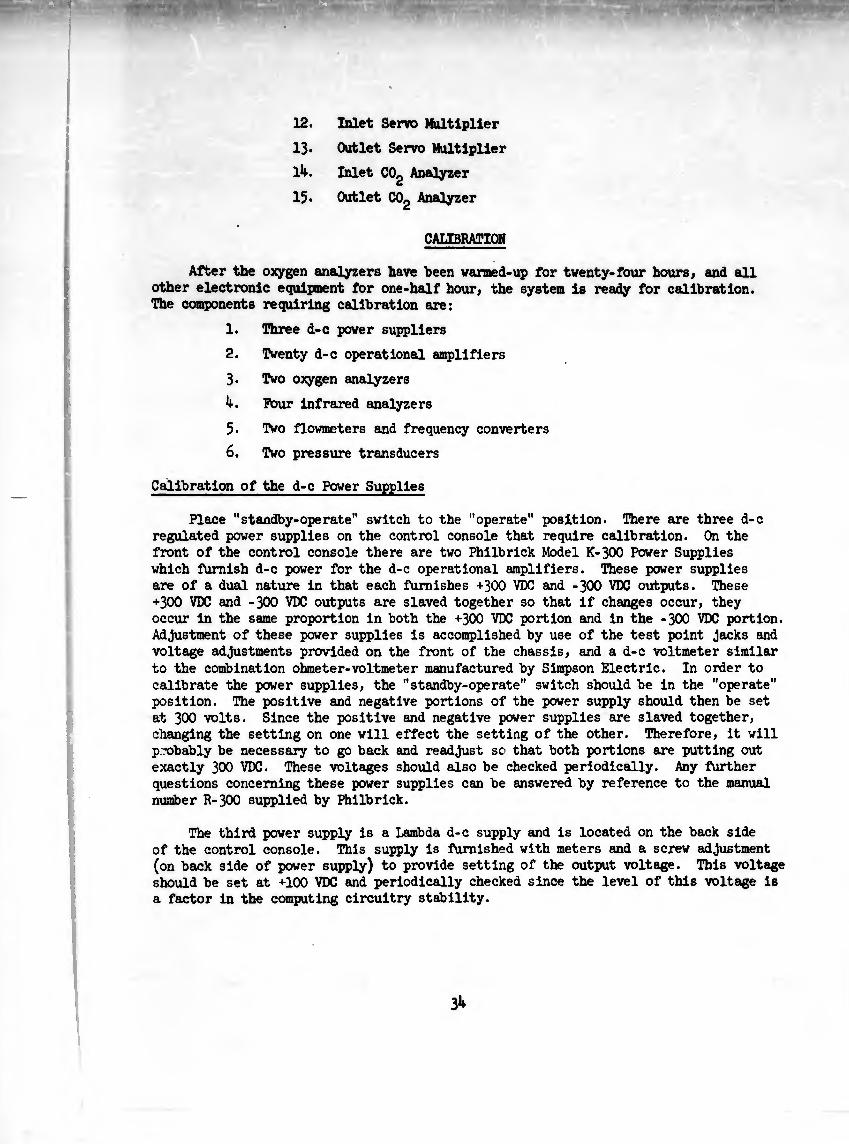
12. Inlet Servo Multiplier
13* Outlet Servo Multiplier
I1*. Inlet COg Analyzer
15* Outlet COg Analyzer
CALIBRATION
After the oxygen analyzers have been varmed-up for twenty-four hours, and «dl other electronic equipment for one-half hour, the system is ready for calibration. The components requiring calibration are:
1. Three d-c power suppliers
2. Twenty d-c operational amplifiers
3« Two oxygen analyzers
4. Pour infrared analyzers
5. Two flowmeters and frequency converters
6. Two pressure transducers
Calibration of the d-c Power Supplies
Place "standby-operate" switch to the "operate" position. There are three d-c regulated power supplies on the control console that require calibration. On the front of the control console there are two Philbrick Model K-300 Power Supplies which furnish d-c power for the d-c operational amplifiers. These power supplies are of a dual nature in that each furnishes +300 VDC and -300 VDC outputs. These +3OO VDC and -300 VDC outputs are slaved together so that if changes occur, they occur in the same proportion in both the +3OO VDC portion and in the -300 VDC portion. Adjustment of these power supplies is accomplished by use of the test point jacks and voltage adjustments provided on the front of the chassis, and a d-c voltmeter similar to the combination ohmeter-voltmeter manufactured by Simpson Electric. In order to calibrate the power supplies, the "standby-operate" switch should be in the "operate" position. The positive and negative portions of the power supply should then be set at 3OO volts. Since the positive and negative power supplies are slaved together, changing the setting on one will effect the setting of the other. Therefore, it will probably be necessary to go back and readjust sc that both portions are putting out exactly 300 VDC. These voltages should also be checked periodically. Any further questions concerning these power supplies can be answered by reference to the manual number R-300 supplied by Philbrick.
The third power supply is a Lambda d-c supply and is located on the back side of the control console. This supply is furnished with meters and a screw adjustment (on back side of power supply) to provide setting of the output voltage. This voltage should be set at +100 VDC and periodically checked since the level of this voltage is a factor in the computing circuitry stability.
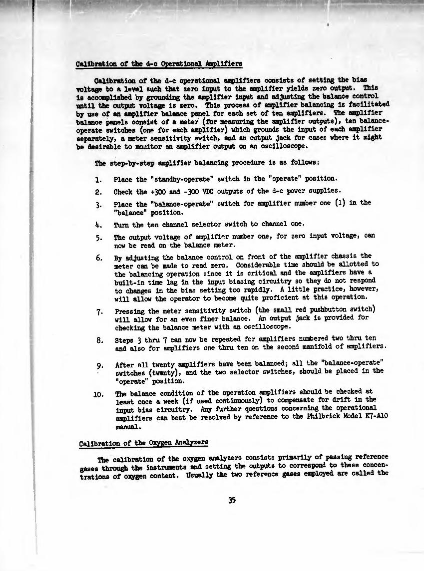
Calibration of the d-c Operational Amplifiera
Calibration of the d-e operational amplifiers consists of setting the bias voltage to a level such that zero input to the amplifier yields zero output. This is accomplished by grounding the amplifier input and adjusting the balance control until the output voltage is zero. This process of amplifier balancing is facilitated by use of an amplifier balance panel for each set of ten amplifiers. The amplifier balance panels consist of a meter (for measuring the amplifier outputs), ten balance- operate switches (one for each amplifier) which grounds the input of each amplifier separately, a meter sensitivity switch, and an output Jack for cases where it might be desirable to moultor an amplifier output on an oscilloscope.
The step-by-step amplifier balancing procedure is as follows:
1. Place the "standby-operate" switch in the "operate" position.
2. Check the +300 and -300 VDC outputs of the d-c power supplies.
3. Place the "balance-operate" switch for amplifier number one (l) in the
"balance" position.
4. Turn the ten channel selector switch to channel one.
5. The output voltage of amplifier number one, for zero input voltage, can
now be read on the balance meter.
6. By adjusting the balance control on front of the amplifier chassis the meter can be made to read zero. Considerable time should be allotted to the balancing operation since it is critical and the amplifiers have a built-in time lag in the input biasing circuitry so they do not respond to changes in the bias setting too rapidly. A little practice, however, will allow the operator to become quite proficient at this operation.
7. Pressing the meter sensitivity switch (the small red pushbutton switch) will allow for an even finer balance. An output Jack is provided for checking the balance meter with an oscilloscope.
8. Steps 3 thru 7 can now be repeated for amplifiers numbered two thru ten and also for amplifiers one thru ten on the second manifold of amplifiers.
9. After all twenty amplifiers have been balanced; all the "balance-operate" switches (twenty), and the two selector switches, should be placed in the
"operate" position.
10. The balance condition of the operation amplifiers should be checked at least once a week (if used continuously) to compensate for drift in the input bias circuitry. Any further questions concerning the operational amplifiers can best be resolved by reference to the Philbrick Model K7-A10
manual.
Calibration of the Oxygen Analyzers
The calibration of the oxygen analyzers consists primarily of passing reference gases through the instruments and setting the outputs to correspond to these concen¬ trations of oxygen content. Usually the two reference gases employed are called the
35
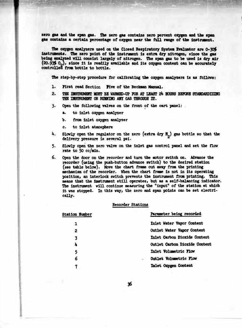
zero gas and the span gas. The tero gas contains zero percent oxygen and the span gas contains a certain percentage of oxygen near the full range of the Instrument.
The oxygen analyzers used on the Closed Respiratory System Evaluator are 0-30)( Instruments. The zero point of the Instrument Is extra dry nitrogen, since the gas being analyzed will consist largely of nitrogen. The span gas to be used is dry air (20.93)( Op), since It Is readily available and its oxygen content can be accurately controlled from bottle to bottle.
The step-by-step procedure for calibrating the oxygen analyzers Is as follows:
1. First read Section Five of the Beckman Manual.
2. THE INSTRUMENT MUST BE WARMED-UP FOR AT LEAST 24 HOURS BEFORE STANDARDIZING THE INSTRUMENT OR RUNNING ANY GAS THROUGH IT.
3. Open the following valves on the front of the cart panel:
a. to Inlet oxygen analyzer
b. from Inlet oxygen analyzer
c. to Inlet atmosphere
4. Slowly open the regulator on the zero (extra dry N ) gas bottle so that the delivery pressure Is several psl. 2
5. Slowly open the zero valve on the Inlet gas control panel and set the flow rate to 50 cc/mln.
6. Open the door on the recorder and turn the motor switch on. Advance the recorder (using the push-button advance switch) to the desired station (see table below). Move the chart frame out away from the printing mechanism of the recorder. When the chart frame is not in its operating position, an interlock switch prevents the instrument from printing. This means that the Instrument still operates, but as a self-balancing indicator. The instrument will continue measuring the "input" of the station at which it was stopped. In this way, the zero and span points can be set electri¬ cally.
Recorder Stations
Station Number Parameter being recorded
1
2
3
4
5
6
7
Inlet Water Vapor Content
Outlet Water Vapor Content
Inlet Carbon Dioxide Content
Outlet Carbon Dioxide Content
Inlet Volumetric Flow
Outlet Volumetric Flew
Inlet Oxygen Content
36
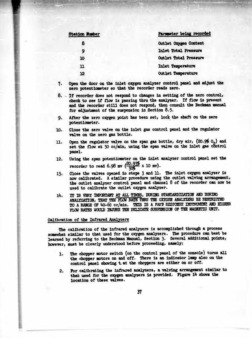
Station lumber Parweter being recorded
8
9
10
Outlet Oxygen Content
Inlet Total Pressure
Outlet Total Pressure
11
12
Inlet Temperature
Outlet Temperature
7. Open the door on the inlet oxygen analyzer control panel and adjust the zero potentiometer so that the recorder reads zero.
8. . If recorder does not respond to changes in setting of the zero controli check to see if flow is passing thru the analyzer. If flow is present and the recorder still does not respond, then consult the Beckman manual for adjustment of the suspension in Section 8.5*
9. After the zero oxygen point has been set, lock the shaft on the zero potentiometer.
10. Close the zero valve on the inlet gas control panel and the regulator valve on the zero gas bottle.
11. Open the regulator valve on the span gas bottle, dry air, (20.Si 0«) and set the flow at 50 cc/min, using the span valve on the inlet gas control panel.
12. Using the span potentiometer on the inlet analyzer control panel set the
recorder to read 6.98 mv x 10 m)•
13. Close the valves opened in steps 3 ®n<l 11. The inlet oxygen analyzer is now calibrated. A similar procedure using the outlet valving arrangement, the outlet analyzer control panel and channel 8 of the recorder can now be used to calibrate the outlet oxygen analyzer.
lU. IT IS VERY IMPORTANT AT ALL TIMES, DÜRING STANDARDIZATION AND DURING ANALYZATIQN, THAT THE FLOW RATE THRU THE OXYGEN ANALYZERS BE RESTRICTED TO A RANGE OF 40-60 cc/min. TTTTfl IS A FAST RESPONSE INSTRUMENT AND HIGHER FLOW RATES WOUID INJURE THE DELICATE SUSPENSION OF THE MAGNETIC UNIT.
Calibration of the Infrared Analyzers
The calibration of the infrared analyzers is accomplished through a process somewhat similar to that used for the oxygen analyzers. The procedure can best be learned by referring to the Beckman Manual, Section 3» Several additional points, however, must be clearly understood before proceeding, namely:
1. The chopper motor switch (on the control panel of the console) turns all the chopper motors on and off. There is an indicator lamp also on the control panel showing t. at the choppers are either on or off.
2. For calibrating the infrared analyzers, a valving arrangement similar to that used for the oxygen analyzers is provided. Figure l4 shows the location of these valves.
37

It is laperatlve during standardization of the Infrared analyzers that the "to and from oxygen analyzer" valves (for both Inlet and outlet) be closed.
The reason for this Is that the infrared analyzers are calibrated at flou rate of around 400 cc/mln. which would permanently damage the suspension of the oxygen analyzers. During operation; that Is, when analyzatlon Is taking place, the sample flows through both, but the flow Is throttled down through the oxygen analyzerr to around 50 cc/mln.
3* Make sure that the proper analysis unit is being calibrated with the right amplifier (they are labeled). Also, make sure, as was pointed out earlier, that the correct calibration data is used since no two Infrared units are the same.
4. Two output instruments (a meter and recorder) have to be zeroed and spanned for each infrared analyzer. On each amplifier chassis there Is an output meter and each output Is also recorded on the multi-point strip chart recorder. On the back of each amplifier chassis there is a potentiometer (which is part of'the filter-attenuator necessary for this recorder) which allows the operator to set the output to the recorder at any level. By the combined use of the gain control (on the front of the amplifier) and this potentiometer (on the back), the meter and recorder levels can be made to correspond to one another.
Calibration of the Flowmeters and Frequency Converter
The calibration procedure for the turbine flowmeters and frequency converters is best described in the Potter Aeronautical 3C-1 Manual. The only additional Information needed is that the system is designed so that the frequency converter1s output will be 10 mv for a flow rate of 1 ft^/min. Therefore, when calibrating the flowmeter it is necessary only to read the flow rate off of the calibration curve corresponding to a frequency of 100 cps, multiply by a factor of 10, and using the gain control (on the frequency converter) set the recorder to this valve. Note that the calibration curves are different from the two flowmeters. Using flowmeter serial number AMF 3/l6-3> the output would be set at 3-35 mv with the 100 cps switch depressed. The output of the other flowmeter, serial number AMF 3/16-2, would be set at 3*5 mv for a 100 cps signal.
Calibration of the Pressure Transducers
The pressure transducers employed are CEC type 4312-A with a range of 0-15 psia. The method of calibrating the pressure transducers is quite single. With the inlet and outlet line to the evaluator open to atmosphere the balance controls on the power supply (inside the big junction box on the cart) are adjusted so that the recorder reads full scale. In this manner the transducer output for an ambient pressure of 15 psia is 10 mv.
OPERATING PROCEDURE
After the system is properly warmed-up and calibrated as per the preceding instructions, evaluation of a closed respiratory system can be initiated as follows:
38
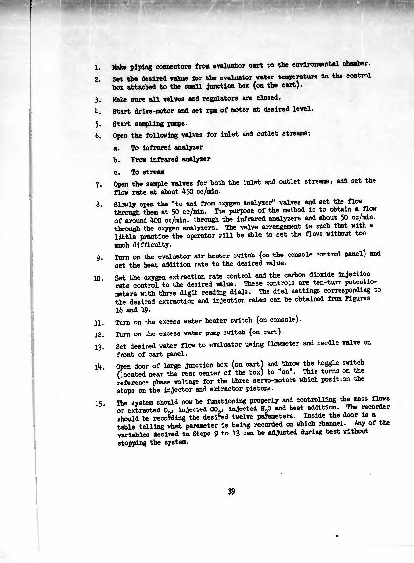
1. M»v«» piping connectors from evaluator cart to the environmental chamber.
2. Set the desired value for the evaluator water temperature in the control
box attached to the small Junction box (on the cart).
3. Make sure all valves and regulators are closed.
4. Start drive-motor and set rpm of motor at desired level.
5.
6.
7.
8.
9-
10.
11.
12.
13.
14.
15.
Start sampling pumps.
Open the following valves for inlet and outlet streams:
a. To infrared analyzer
b. Fran infrared analyzer
c. To stream
Open the sample valves for both the inlet and outlet streams, and set the
flow rate at about 450 cc/min.
Slowly open the "to and from oxygen analyzer" valves and set the flow through them at 50 cc/min. The purpose of the method is to obtain a flow of around 400 cc/min. through the infrared analyzers and about 50 cc/min. through the oxygen analyzers. The valve arrangement is such that with a little practice the operator will be able to set the flows without too
much difficulty.
Turn on the evaluator air heater switch (on the console control panel) and
set the heat addition rate to the desired value.
Set the oxygen extraction rate control and the carbon dioxide injection rate control to the desired value. These controls are ten-turn potentio¬ meters with three digit reading dials. The dial settings corresponding to the desired extraction and injection rates can be obtained from Figures
l8 and 19. Turn on the excess water heater switch (on console).
Turn on the excess water pump switch (on cart).
Set desired water flow to evaluator using flowmeter and needle valve on
front of cart panel.
Open door of large Junction box (on cart) and throw the toggle switch (located near the rear center of the box) to "on". This turns on the reference phase voltage for the three servo-motors which position the
stops on the injector and extractor pistons.
toe system should now be functioning properly and controlling the mass flows if extracted 0o, injected CO., injected H.0 and heat addition. The recorder ihould be recording the desiïed twelve parameters. Inside the door is a ;able telling what parameter is being recorded on which channel. Any of the inriahles desired in Steps 9 to 13 can be adjusted during test without
stopping the system.
39
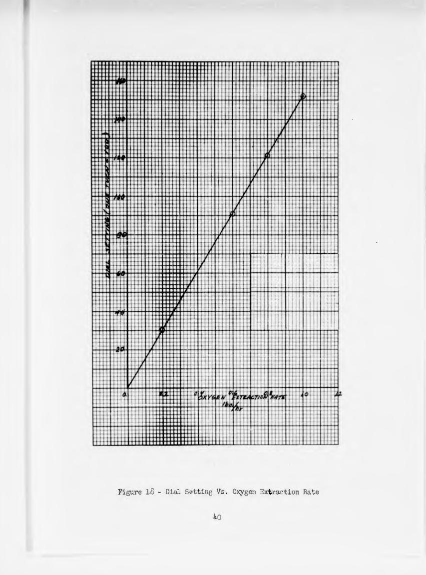
Figure l8 - Dial Setting Vs. Oxygen Extraction Rate
Uo
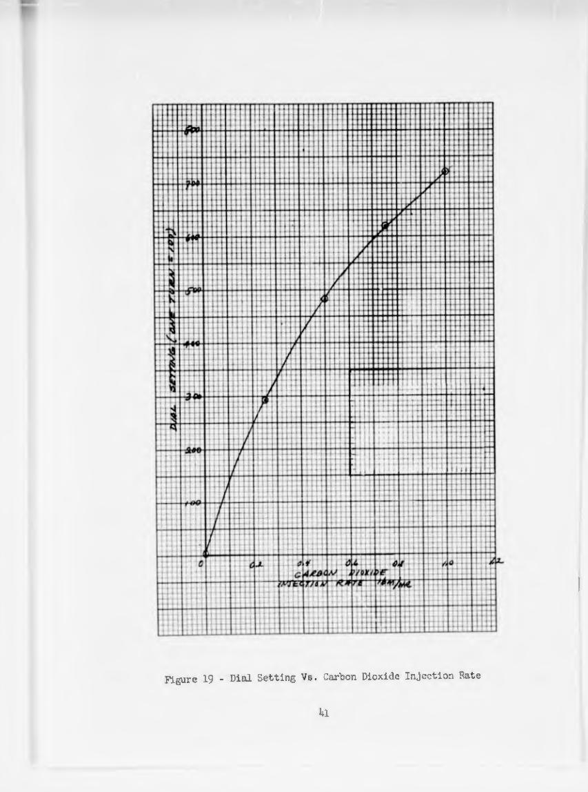
Figure 19 - Dial Setting Vs. Carbon Dioxide Injection Rate
hi
TROUBLE SHOOTING
During operation ol the Closed Respiratory System Evaluator there are several occurrences that should be monitored because they Indicate that the system is not functioning properly. These occurrences will generally indicate the failure of a component or a part of the system. The following procedure will facilitate the discovery of such failures.
1. Frequent visual Inspection of the control console's indicating lights will Inform the operator of a power failure to either the entire system (main power light) or to a specific component (component lights).
2. Visual Inspection of the green indicating lights on the oxygen analyzers will infoni the operator of a power failure to this equliment.
3* Occasionally the front doors of the console should be opened and the Indicating lamps for the ac aid dc power on the power supplies and operational amplifiers should be checked to see if they eure lit.
4. There are windows in the smeúJ. doors on the console to permit visual inspection of the operating condition of the amplifiers. Through these windows the limit lights for the amplifiers are visual, thus allowing the operator e means of noting when the summing point voltage of a particular amplifier is exceeding the capacity of the amplifier. Ibis light indicates that something is not operating properly in the computing circuitry. The problem area should be found immediately, but it is not necessary to turn the system off (or to "standby") as the amplifiers are protected from self- destruction and short periods of over-limiting will not harm them.
5. Occasionally during the operation of the system the four infrared and two oxygen analyzer cases should be checked to see if the heating elements are functioning properly. The placing of a palm on the case to see if they are warm to the touch should suffice for a routine check-point procedure.
6. The recorder should also be periodically monitored to see if any extraneous data, such as large changes or zero readings, is being received.
7. Periodically the flow rates through the infrared and oxygen analyzers should be checked to see if they are within their limits. Also the flow rate of the amount of water added to the evaluator should be checked to see if it is maintlnlng its setting.
8. Occasionally, the excess water heater in the environmental chamber should be checked to see if the water is being vaporized or not.
9* Periodically the three servo motors which adjust the stroking length of the pistons should be monitored to determine if their operation is normal. The system is designed to null about a point, that is, the drive gear should move back and forth about a point (if the settings of variables are not changed). Due to changes occurring in the stream composition the balance point will move in one direction or the other, but in all cases, the system should null. If the system tends to drive in one direction all the way to the stop and stay there, then something is wrong in either the instrumenta¬ tion or computing circuitry. A visual inspection of the amplifier limit lights and/or the recorder readings will facilitate the determination of
42

1 > mti l'* r'^Xû Äti
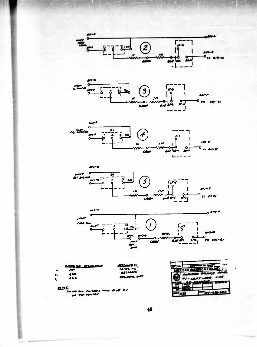
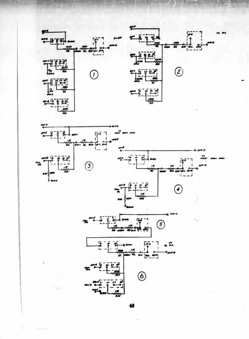
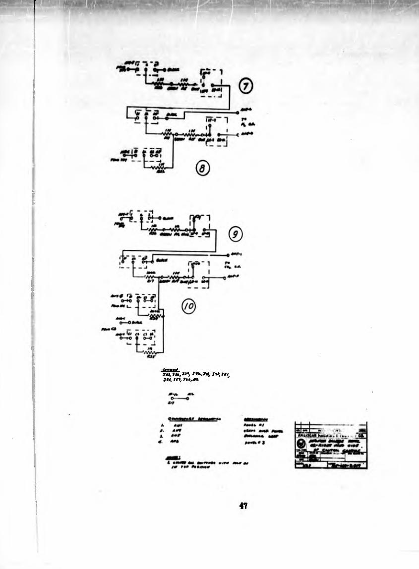
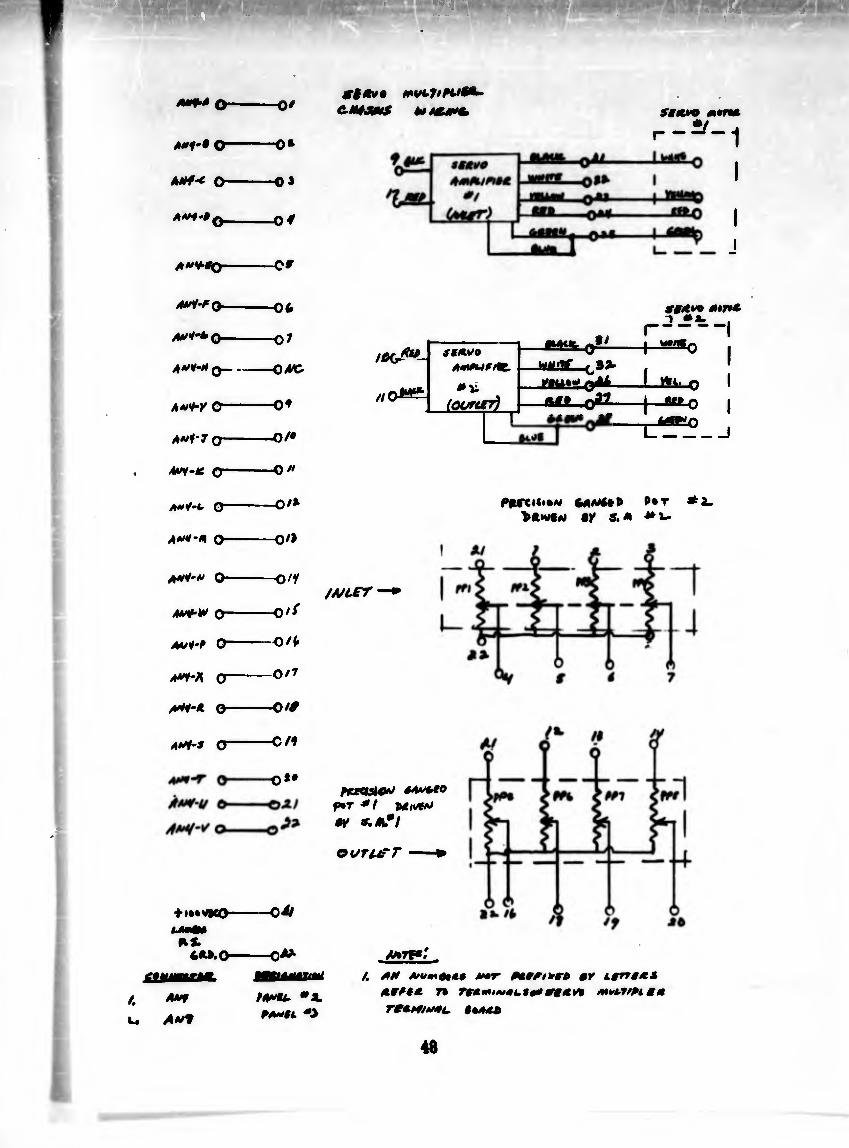
th« problea am. Che« the probI«i «m 1« located, the trouble ahootla* procesa reaolres Usloallj to one of rsferring to the aanufacturer'a *nual and foil owing their reoosnandations for trouble footing that particular piece of iaatruMBtaUou. lb aid in trouble shooting a set of wiring diagrams (pages U through 48) for the console and cart are included* These drawings show the interconnections betwsen transducers, conputer circuitry, recording, and controlling elements*
43

á»i-f
/UH-» ^r» •tx-c-i
Oi/rur
4M'* O—
1/ -k3
1. »t/t-r
o rm nt- -*/
AVi-Z
44
i»»*#
**“•**»-> »I »I fg') ¡i«
^4--- 'í 1 1-»Î3
A*f*
~° f •»’ »!
*»*-•
O- ® m.
-VW'—o-
, A'-f
!í -VW—O—Ö O
_J
A**’*
ttturr Ao/num
r"1 ¡I i’ ~ üuJ (?) i tf-r
-VW~c4-l
’1
-WV'-O-WV'—o—C 0-4- (juM tuÁif’t »^Oj
i$JtWT
r**Q, **> _ I » A
•—1° ■•f‘"«1 (j) i-« 1
A»fT
0 n **-&
**h-T
ro tñ »•
_0 A**’*1
vr""“1
/*»«*■< M>J-* -O O
/•at* éU*
AAHK.
9*1-41
/. a. *.
C******* *•*•** ar,t‘ 4*» 4"4 ñ*t%
A+~0* «V
<»««*• ««4. **'Tt*r* tat r* Aa*t9"*
mana ßamf *t
^itnilCAW MACHIH¿ *
45
rm
7M ÏM.W»/ TU. Hl JH, tri. U», mi
47
4*f'» O"
A*f-* O-
A**'*,
-0/
-o*
-0»
-o#
-C»
9%ã>i% mvLJtAUi OHsms t*t sattyo mtna
r_^_1
I
/. u
AAi-fQ-
Atl-tQ-
4**4 0~
4*v*r o~
4*f-T O'
4*r-<c c
O"
4**-4 0-
4*4-* 0-
4*** <T
tl»»V|CO-
*s. 60.0-
4*T
-06
-Ql
-040
-04
-O/*
-O*
-O/*
-o/>
-o/y
-0// 4**I4 0~
4«/** O“——O/fr
4*y-^i o-0/7
4*4-4 0-O/*
-C/1
o*#
-o4f
-0^
iCfJ**-
//
StAVO
AmßUfMt.
lOOrirr)
.*/
SfA* A*7*A
-j—^£3*0 wi/nf caa-
i i
䣣__o22-J—S1E_q J 6>tf*0
i_
Pitrciti*M 64a/*** p*t 4 a_ >4h/C* CK 5.4 *l~
/4/¿rr —*
fiUOM&O *4*»fO
P»T */ M/t** •4
oururr —»
/4**- *X P4**& *■>
/. 44 AtvmAtAt **r ßAMAOrr* AY LgrtãA*
45**4 7» Tf*i*i~41.10* A Y» MUl/Piêm
Te**4/»*L. *«444
48

iilüflí! ààâiliaiïSôï • • • • •
“HBe5 >
a •
>>
3Í^, ief^iiiss!í
iïëhil _ -i O <u 0 S a 3 e ? « S S » O <M
£ ° *** «
m U «CÃ
! 5¾¾ &y
5^2213
B-a -
^¿1 » >»5 CM
m i
os H Û ca •<
S3 * « í^» (U « ¿
2 rt c« >
'S ^ a u ta c « o h u
§• § o â- 2 U JZ V T*
u V * u zk*** J • ° >>_
4) iJSi 1 e 3 - I Ö M 5 ® > 5 ‘ 1
I W
15 i 5
3 S e «-o « S « u a û
- a ai ui s « -' S 5* K U tí ® ® £ — y 4) 4» * a - -a u
ílss sl¿s s ?sl s %i »l^l cC.® *
J S « 1 u 3 çí o ï 2 “ ^ •° £ 3 e
°ú\\ 2.5 2P eS» «o o> S Ml
= 2|S lis-
w (4
d 14
si *Iá srS sl® «c¿ «\ 2 WPN i5¿
*2 « -°c O—o — o — cu a, S
O hl «
S. a S2 (S2 2“ “ •o 2 e a
i < 3 ¿ J S
S* a 0) u V 4í
c « 3 ^ ^ 5 j !
4» 0 “O S C 2 õ
I ï SÍ S * * 41 o S
d T5 U • ^ ï +- ü C ^ ?v « c ^ ¢, « o S « « c u c «, - u 3 <« >2 « S 2 2-g 52« S 3:°
§-Sl3«ïi
1cS:S!s «llsssl
o « " - o T3
.5 ':2sï| ï ® c 5 ¡l|ü«w _, o 4» e - 3 = ï au
illlfl ! u ** Ç 5 -
a c « ^ p «
5!U45|
fisSSfe
LI^I
. I î I J I

UNCLASSIFIED
UNCLASSIFIED