M A T U R E H E I G H T O F T R E E W I T H I N R I G H T - O F W
220kV TOWE
K.K.Shyamali February 2010
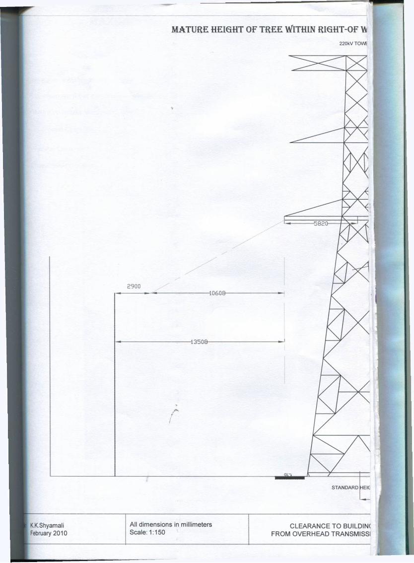
A Y ( R O W ) W I D T H F O R 2 2 0 K Y ( Z E B R A ) & 3 3 K V L I N E S
R
Annex 3-7.5
HT TOWER
?0610-
STANDARD HEIGHT TOWER
3S ON LINES w Master of S c i e n c e Dissertation
Department of Electr ical Engineering University of Moratuwa
Supervised By: Prof. J. R. Lucas Eng. W.D.A.S. Wijayapala

MAXIMUM HEIGHT OF BUIDING A T WITHIN RI 132
No Building constructions allowed at mid-span position
Maximum height of construction allowed at mid-span within minimum ROW
Maximum height of construction allowed at mid-span within flexible range of ROW
- Horizontal Cearance
• Vertical Cearance
-Transitional (Vertical) Cearance
4824 STANDARD STANDARD
M
KK.Shyamali February 2010
All dimensions in millimeters Scale: 1:125
CLEARANCE TO BUILDIN( FROM OVERHEAD TRANSMISSI
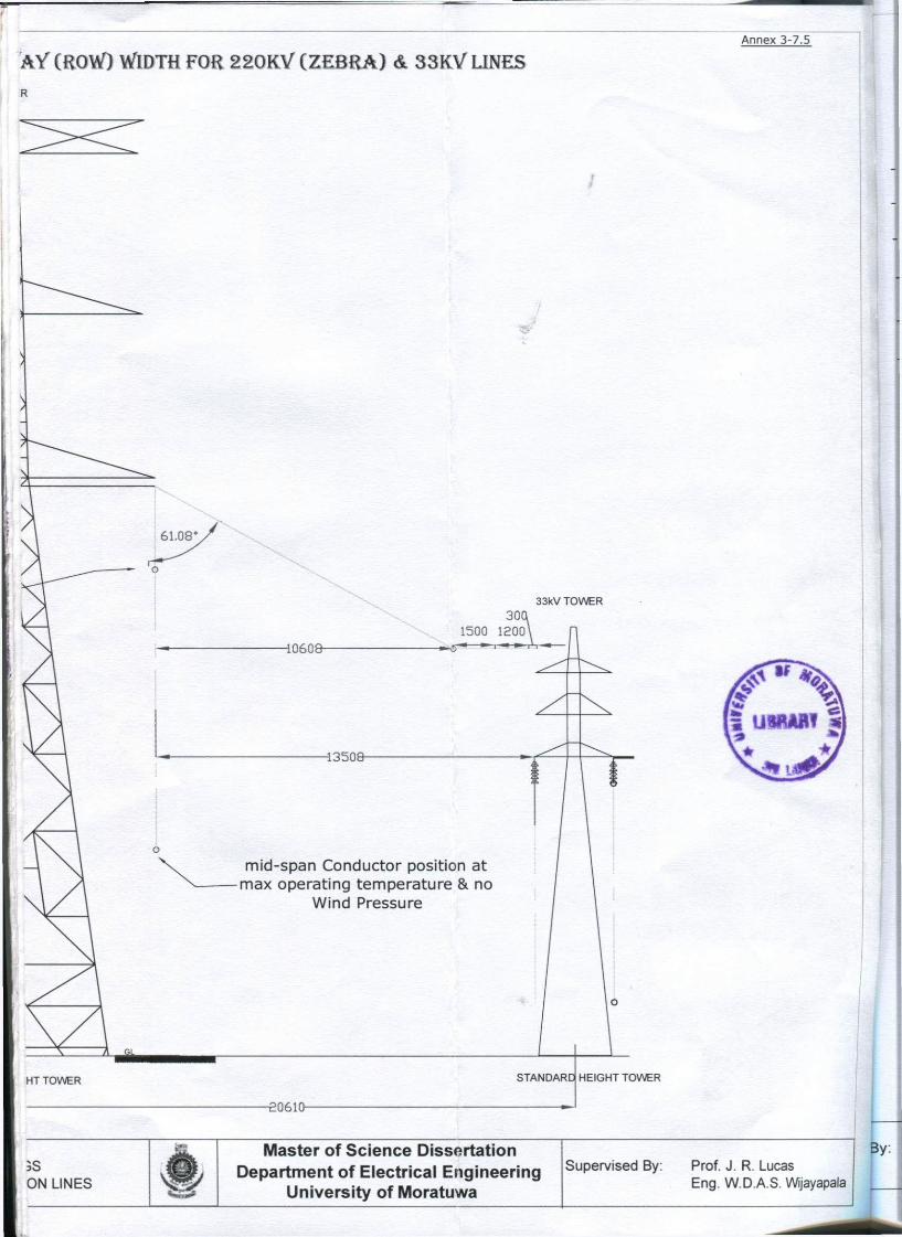
SHT-QF-WAY (ROW) WIDTH O F I 3 2 I O / ( Z E B R A ) U N E Annex 3.8.1
kV TOWER
Assumpt ion: two towers are located at the same ground level
o o AVA»*V»»
A»*»*»A»**»T4»4»4l»*nV»**T.,T»»
iViVtViViWi'AVAWAf AVAVAVAVAVAVAVA
AVAWAVAVATAVAWAT
-W*W*VAV*WAVAVAW*W.' fAVAWAVAWAVAWAWil
A V A ' A V A V A T A W A W A W A T T A W A W A V A T A W A T A W A T A WAWAWAWAWAWA»AnV4WA»»' A V A W A W A V A V A W A V A T W A V A V A W A W A W A V A V A A V A W A V A V A V A V A V W A V WAWAWAmVAWAWA»AV«* A m V A W A W A V A W i W A f A V A W A T A W A W A W A W A W A V W A ' A W A W A ' A W A W A W A A V A V A V A V A V A V A V A ' A V VAWAWAWAWA'AWAWAWAWA A'A'AVAVAVAWAWAWil! A V A V A W A W A V A W A V A T V A W A V A W A T A W A ' A V A W A
*V»»*',*''t»*».''»»*»«'»»»*V»»i»*»4.'A»*Vi»i»k*»»*r
tAWAV>VAWAWAmvAWAW«WA A V A V A W A V A V A V A V . ' i V i ' ATAVATAWAWAWAWAVAWA*A' A W A V A V A V A V I ' A V A ' A W A T VAVAWAVAVAVAWAWA AVAVAWAVAWAVAVAV •AWAVAVAVATA'AWAVA'AVA' AVAVtVAVAVAVAVAWAT WAVAVAVAWAWAVAVA AVAWAWAWAWAWAVATAWAW W*W*TAAmWAVAWAW«»AV*TA; A V A V A V A ' A W A V A V A V A V WAWAV*W»WAWA*AWAV»W»' A W A V A W A ' A V A V A W A V A T
4824
ax. ROW
.s ON LINES
Master of S c i e n c e Dissertation Department of Electr ical Engineering
University of Moratuwa
Supervised By: Prof. J. R. Lucas Eng. W.D.A.S. Wijayapala

MAXIMUM HEIGHT OF BUIDING ALONG THE S P A N WTl
L L L l Maximum height of construction allowed at mid-span within minimum ROW
3 L"
- Increased height of safe region for construction of buildings for spans higher than 50m & locations at distance f rom one tower is less than 125m
- No Building constructions allowed at mid-span position
- Inceased Height of safe region for spans higher than 50m & locations at distance from one tower is less than 125m
(But C o n s t r u c t i o n s not a l l o w e d d u e to the r isk of conductor fal l ing on Bui ld ings )
- Horizontal Cearance
Vertical Cearance
Transitional (Vertical) Cearance
H Conductor attc
point
Conductor position at max operating temperature & no
| Wind Pressure at 250m span
. K.K.Shyamali All dimensions in millimeters CLEARANCE TO BUILDINGS February 2010 Scale: 1:125 FROM OVERHEAD TRANSMISSI

Annex 3-8.2
'HIN RIGHT-OF-WAY (ROW) OF 1 3 2 K V ( Z E B R A ) LINE 1 3 2 k V T O W E R
Assumpt ion : two towers are located at the same ground level
No negative tower body extensions used
STANDARD HEIGHT TOWER
At Master of S c i e n c e Dissertation • AND ON LINES w Department of Electr ical Engineering
University of Moratuwa
Supervised By: Prof. J. R. Lucas Eng. W.D.A.S. Wijayapala
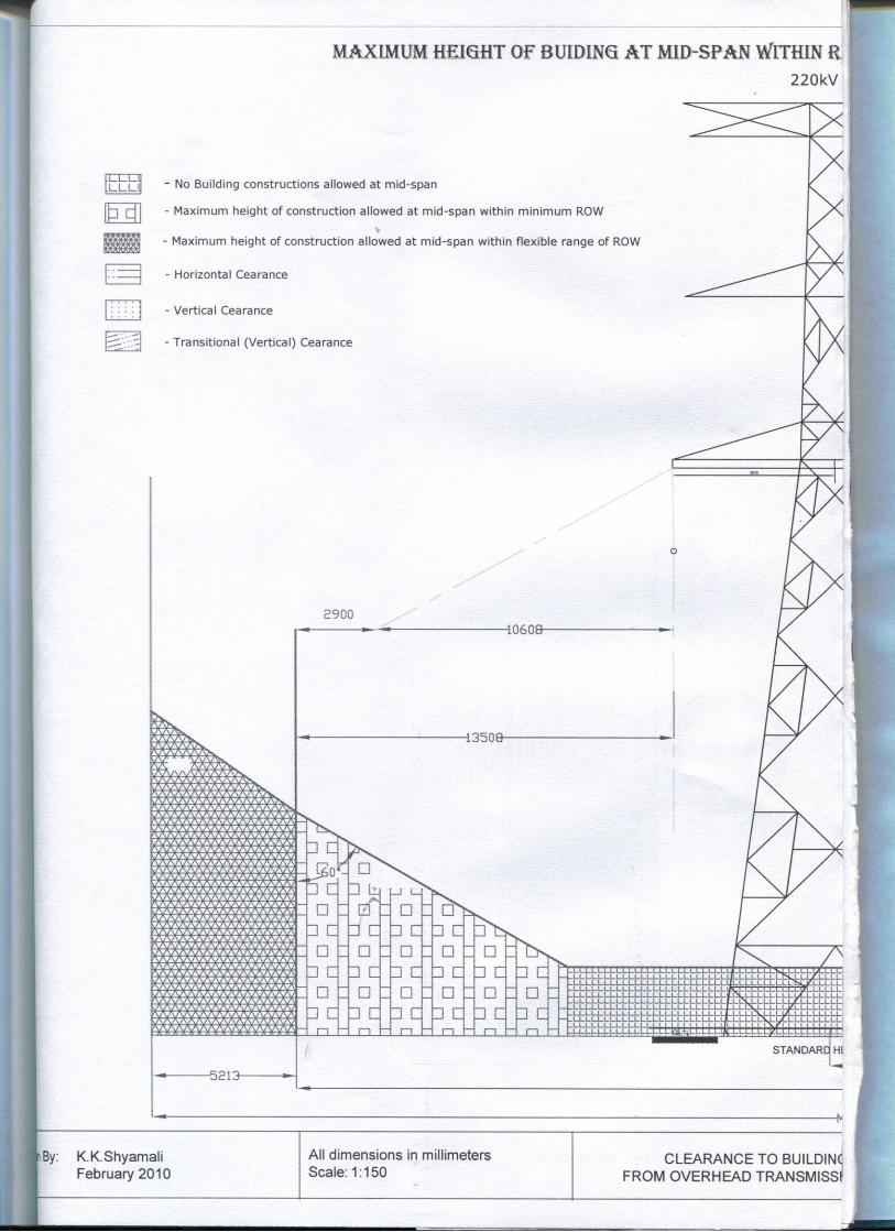
M A X I M U M H E I G H T O F B U I D I N G A T M I D - S P A N W X T H I N R
2 2 0 k V
u n a LL.LI
• d
- No Building constructions allowed at mid-span
- Maximum height of construction allowed at mid-span within minimum ROW
- Maximum height of construction allowed at mid-span within flexible range of ROW
- Horizontal Cearance
- Vertical Cearance
- Transitional (Vertical) Cearance
2900
-5213-
40608-
13508-
.LLLL.LL.LLLLLLL.LL LLLLL.LL.U_ L L L L L L L L L L .LLLLLL.L.LLL.LLLLL
. L L L U _ L L L U _ L U _ L l —LLLLLLLLLO
.LL.LL/L.L.LLLI
LLLLLULLLLLLV
STANDARD HI
i By: K.K.Shyamali February 2010
All dimensions in millimeters Scale: 1:150
CLEARANCE TO BUILDINd FROM OVERHEAD TRANSMISSr

Q H T - O F - W A Y ( R O W ) W I D T H O F 2 2 0 K V ( Z E B R A ) L I N E
TOWER
7 T
Annex 3-8.3
> Assumption: two towers are located at the same ground level
:IGHT TOWER
49:29--ROW-
-5213-
RDW-
5S DN LINES
Master of S c i e n c e Dissertation Department of Electr ical Engineering
University of Moratuwa
Supervised By: Prof. J. R. Lucas Eng. W.D.A.S. Wijayapala

M A X I M U M H E I G H T O F B U I D I N G A L O N G T H E S P A N W I T H I N
220kV
n r n i LLLL
- Maximum height of construction allowed at mid-span within minimum ROW
- Increased height of safe region for construction of buildings for spans higher than 50m & locations at distance from one tower is less than 150m
- No Building constructions allowed at mid-span position
- Inceased Height of safe region for spans higher than 50m & locations at distance from one tower is less than 150m
(But Constructions not al lowed due to the risk of conductor falling on Buildings)
- Horizontal Cearance
- Vertical Cearance
- Transitional (Vertical) Cearance
K.K.Shyamali February 2010
All dimensions in millimeters Scale: 1:150
CLEARANCE TO BUILD. FROM OVERHEAD TRANSMI

R I G H T - O F - W A Y ( R O W ) W I D T H O F 2 2 0 K V ( Z E B R A ) L I N E
TOWER
Annex 3-8.4
Assumption: two towers are located at the same ground level No negative tower body extensions used
INGS SSION LINES
Master of S c i e n c e Dissertation Department of Electr ical Engineering
University of Moratuwa
Supervised By: Prof. J. R. Lucas Eng. W.D.A.S. Wijayapala

M A T U R E H E I G H T O F T R E E W I T H I N R I G H T O F -1 3 2 k V TOWER
8184 -8184
105
STANDARD HEIGHT TOWER
V V V V
v v v v V v V V V V v v v v v v v v v v v 7 v v v v v v v v v y g f V V V V V V V V V V V )
v v v v v v v v v v"ty v v v v v v v v v v v 7 V V V V V V V V V V 1 " 7 V V V V V V V V V V 7 V V V V V V V V V V '
a,v„,a g j fcsu i &„s,a
v v
V V
V V V j
V 7 ' V ' V V F y '
18944
-ROW-
-Max. ROV
K.K.Shyamali February 2010
All dimensions in millimeters Scale: 1:150
CLEARANCE TO BUILDINC FROM OVERHEAD TRANSMISSI

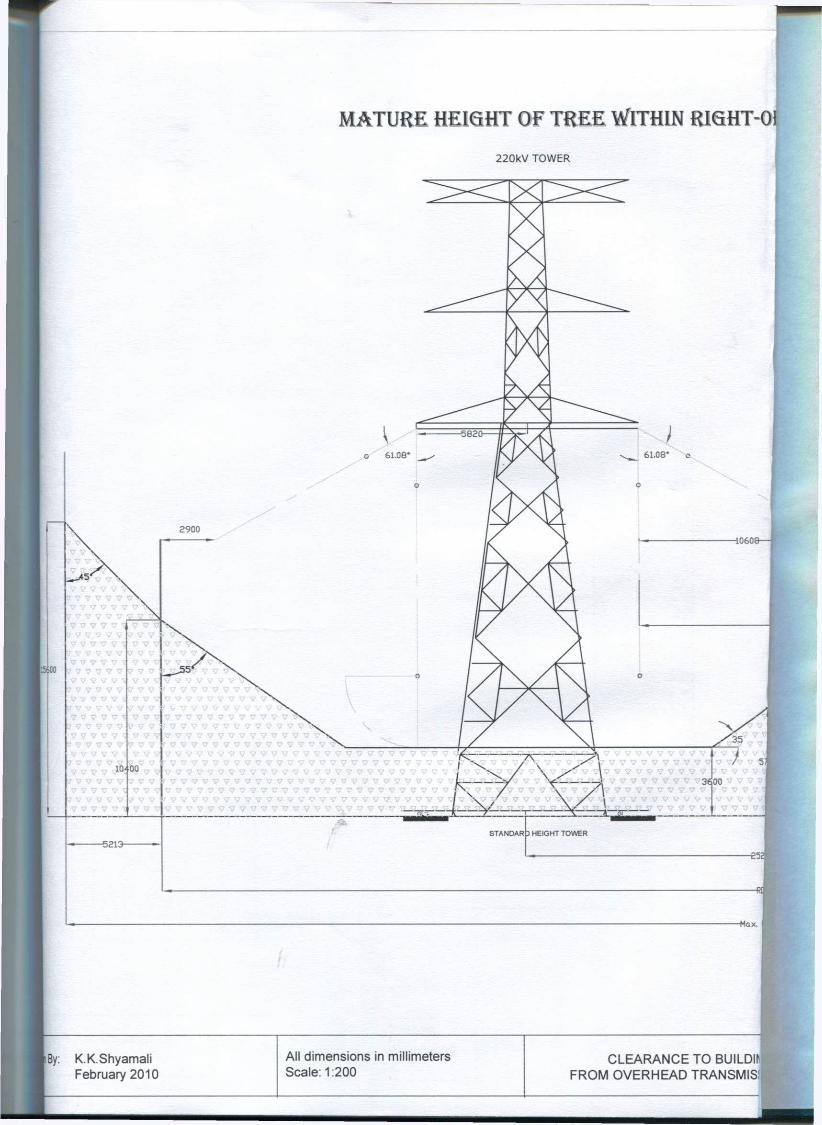
MATURE HEIGHT OF TREE WITHIN RIGHT-OF WAY (ROW 220kV TOWER
o 61.08*
2900
-45'
v v v 7 v ',' SN
7 ? ? ? 9 ' V 7 7 ? 7
7 7 7 7 7 ' 7 7 7 7 7 7 V 7 7 7
7 7 7 7 V 7 7 7 V 7
7 V V V V 7 V V 4) ' 7 7 7 7 !
7 '
' 7 7 V V V 7 7 7 7 7 ' 7 7 7 7 7 7 7 7 7 7 ' 7 7 7 7 7 V V V V V ' V V V V V
7 7 V V V V i
V V
7 7 7 7 7 V '
7 7 V 7 7 V
-10608-
7 7 7 7
V V V V V V Y V 7 V V 7
W 7 « 7 7 77;7 7 7 7 7 7 7 7
V V 7 V V V 7 7 7 7 V 7 V V 7 7 V 7 7 7 7 7 V V V 7 V 7 ' 7 V V V V V 7 7 7 7 7 7 7 7 7 7 7 7 7 7 7 7 7 7 7 7 V V V
MATURE HE1QHT OF THE TREE ' 7 7 7 7 7 7 7 7 V V V V ' V V V V V 7 V V V V V V V 7 7 7
61,08*
-3800—
I 7 7 7 7 V 7 7 7 7 7 ' 7 V V V V V V 7 7 ? ' ' 7 7 V V V V 7 V V V V V 7 7 7 V V V 7 7 ' ' V V V V V V V V V 7
7 V V V V V V V v 7
3y: K.K.Shyamali February 2010
All dimensions in millimeters Scale: 1:175
CLEARANCE TO BUILDINC FROM OVERHEAD TRANSMISSI
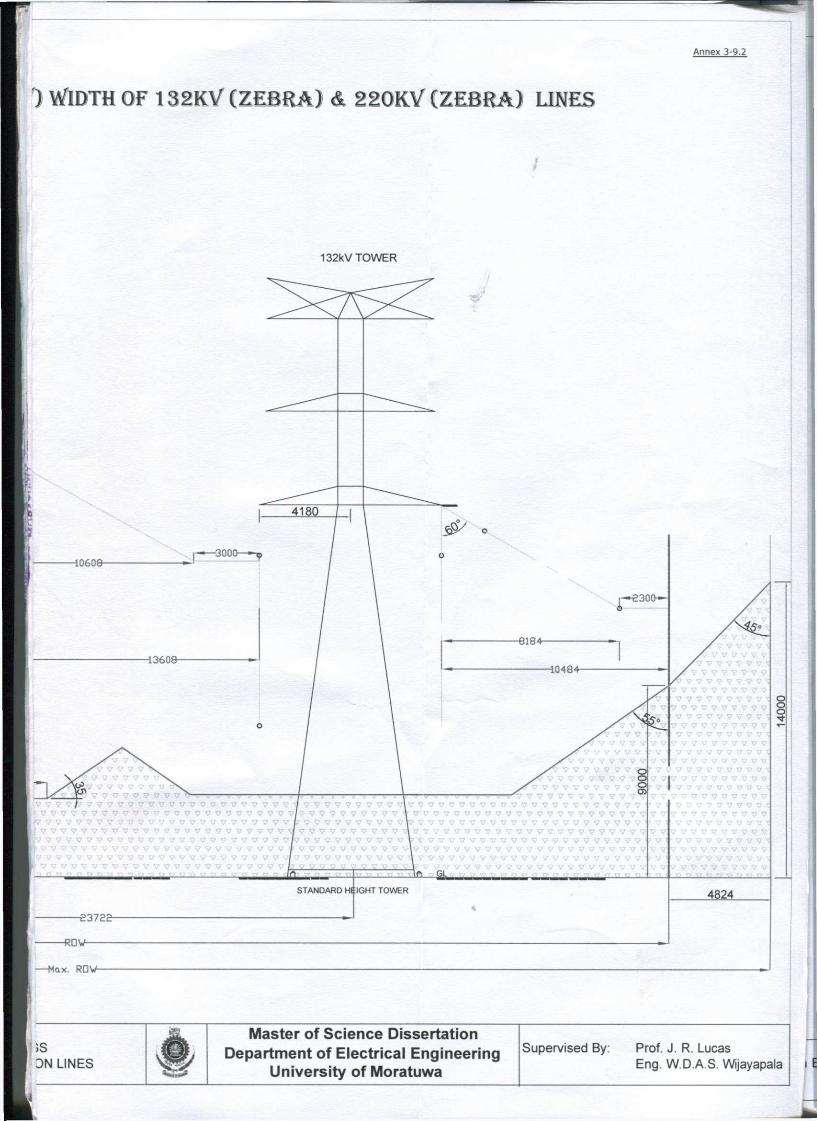
Annex 3-9.2
) WIDTH O F I 3 2 K V ( Z E B R A ) & 2 2 0 K V ( Z E B R A ) LINES
132kV TOWER
JS DN LINES
Master of S c i e n c e Dissertation Department of Electr ical Engineering
University of Moratuwa
Supervised By: Prof. J. R. Lucas Eng. W.D.A.S. Wijayapala

)ISSII/\ISNVcll aV3H_J3AO l/\IOcld ONianina 01 aoiwcivano
9Z I . : | . : 8 |B0S SJ3)8UJ|| | !LU ui suoisuaiuip ||V
01,03 AjBmqsd
it
011H9I3H a a v a N v i s
2 w T i A A A A A A A A A A A A A A A
| . A A A A A A A A A A A A A A
A A A A A A / | A A A A A A A A A
I - A A A A A A A A A A A A A A A A A
> A * * A A A A A
A A "ZT --"It. _i _i i- £. __~A Z T A A _i i i fllY £r7_
A A A A A A A | A A A A A A A A A A A A A A A A A A A A A A A A g j A A A A A A A A A A A A A A A
A A A A A A A A A a c . A A A A A A A A A A A A A A A A A A A A A A A
A A A A A A A A A A A A A A A A A A
A A A A A A A A A A A A A A A A A A A
A A A A A A A A A
^ A A A A A A A A A A A A A A A I A A A A A A A A A A A A A A A
^ A A A A A A A A A A A A A A A A A A A A A A A A A A A A A A
A A A A A A A A A A A A A A A A A A A A A A A A A A A A A A
A A A A A A A A A A A A A A A A A A A A A A A A A A
A A A A A A A A A A A A A A A A A A A
A A A A A A A A A l A A A A A A A
A A A A A A A A A A
A A A A
A A <
A A i
A A i . A A , A A
A A
A A
A A
A A
k A A
A
A A A A A A A A . , A A A A A A A A A A A A A A A A i L A A A A A A A A A A A A A A A A -» A A A A A A A A A A A A A A A A . . A A A A A A A A A A A A A A A A /
<gA A A A A A A A g A A A A A A A
A A A A A A A A A A A A A A A A A
A A A A A A A A A A A A A A A A A 4
A A A A A A A A A A A A A A A A A
A A A A A A A A A A A A A A A A A
A A A A A A A A A A A A A A A A A i
A A A A A A A A A A A A A A A A
A A A A A A A A A A A A A
A A A A A A A A A A
A A
08 i V
y 3 M 0 1 MZ£l
V M - J 0 - 1 H 9 I H NIH1IM 3 3 H 1 JO .LH9IHH H H n i Y W
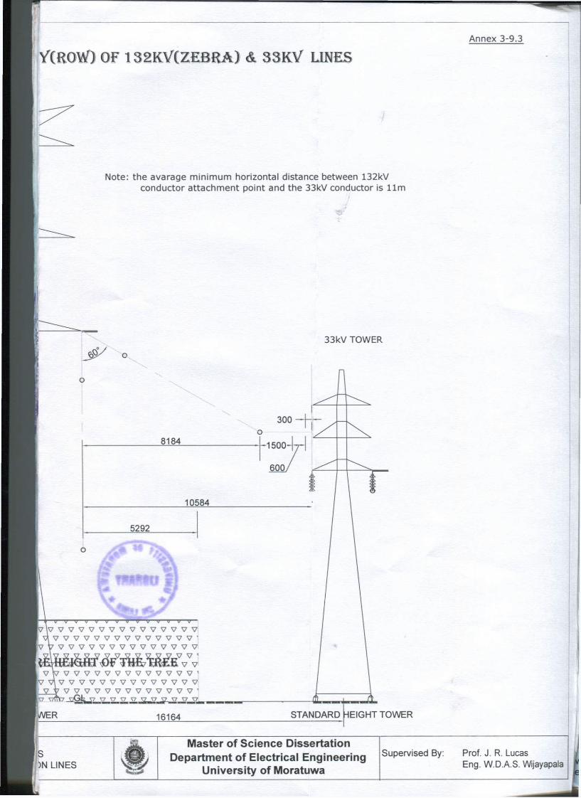
YimM) OF 1 3 2 K V C Z E B R A ) & 3 3 K V LINES Annex 3-9.3
Note: the avarage min imum horizontal distance between 132kV conductor at tachment point and the 33kV conductor is 11m
33kV TOWER
8184
10584
5292
V V v w v v v v v v v v v v v v v v
V V V V V V V V V V V V V V ' 7 V V V V V V V V V V V V V V V
^ W v v v v v v v v v v v v v * V V V V V V V V V V V V V V
V V V V V V V V V V V V V ' ' " ^ * H m P V7 T7 T7 j | 7 ̂ 7 X7 Y7|
ii/VER 16164 STANDARD HEIGHT TOWER
s ')N LINES
* K 5
Master of S c i e n c e Dissertation Department of Electr ical Engineering
University of Moratuwa
Supervised By: Prof. J. R. Lucas Eng. W.D.A.S. Wijayapala
M A T U R E H E I G H T O F T R E E W I T H I N R I S H T - 0
220kV TOWER
15600 ' 7 7 7 V 5 • 7 V V V t 7 7 7 7 1 7 v v v v \
7 V 7 V 7 7 7 7 V '
7 7 7 7 7 7 7 7 7 7 : 7 v v v
7 7 7 V 7 V 7 V V ' 7 7 7 7 1 7 7 7
7 V 7 V V 7
7 7 7 7 7 7 X 7 V
K> V 7 7 V 7
7 7 7 7 V 7
7 7 Vl
7 7 7 10-00
7 V 7
5 3 1 3 -
7 V 7 7 7 V "i 7 7 7 V 7 7 ^ 7 7 7 7 7 7 ^
7 7 7 7 7 7 V 7 V 7 V V 7 V 7 V 7 7 V 7 7 V 7 V 7 7 V 7 V 7 7
• v ' V V V V V V V 7 V V V V V V V V V V V V V V V 7 V V " | f " " " 7 7 7 7 7 7 7 7 7 7 7 V 7 V 7 7 7 7 V 7 7 7 7 7 7 7 V V V V 7 V V V 7 V V V V V V 7
' 7 V V 7 V V 7 7 V 7 7 7 V V 7 > 7 7 v 7 7 V 7 7 V 7 7 V 7 V V 7 3 ^ 0 0 r V 7 V V V 7 V V 7 V 7 7 V V V 7 \ r
T7 <•» t™ TJS .
-Max. I
By: K.K.Shyamali February 2010
All dimensions in millimeters Scale: 1:200
CLEARANCE TO FJUILDIfJ FROM OVERHEAD TRANSMIS!; ;
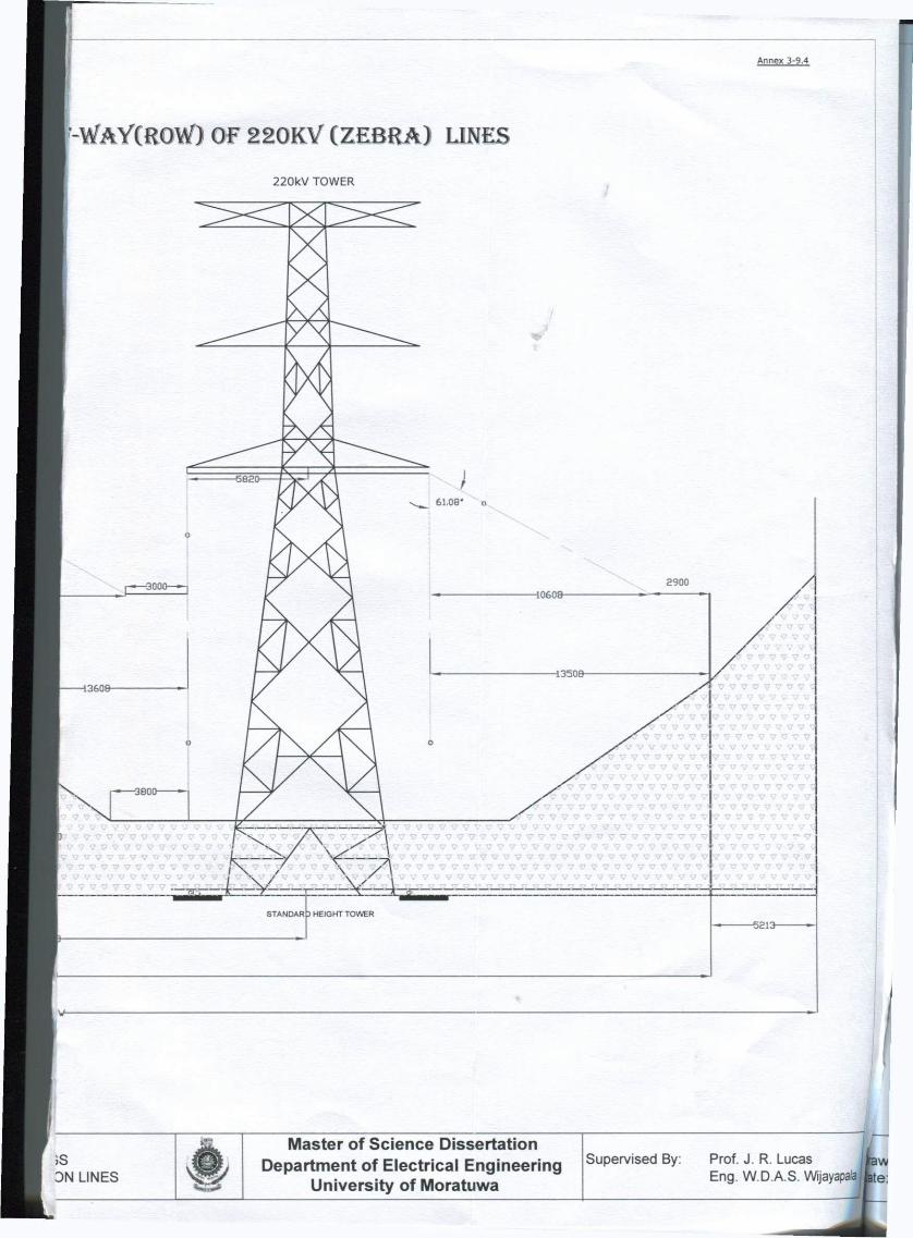
Annex 3-9,4
2 2 0 K Y ( Z E B R A ) LINES 220kV TOWER
V V V V V V V V V V V ' - j 7 7 V V 7 , V 7 V V V V V 7
> V 7 V 7 v v v v 7 7 v v 7 ' V 7 7 V 7 7 7 V 7 V 7 V 7 V V V V V 7 7 V V V V V V V V
• 7 7 7 v v v v v v v v v i
7 7 V 7 V 7 7 V 7 7 7 V 7 7 7 7 7 7 7 7 7 7 7 7 7
• •
V V V V 7 V 7 7 V V 7 V V 7 V V V ? 7 7 V 7 7 V 7 7 7 7 7 V 7 7 7 V 7 7 V 7 7 V 7 7 7 V 7 3 7 7 7 7 7 7 7 7 7 7 7 7 7 7 7 7 7 7 7 7 7 7 7 7 7 7 7 '
,7 7 7 7 7 7 7 7 7 7 7 7 7 7 7 7 7 7 7 7 7 7 7 7 7 7 7 ' V V 7 V 7 V V 7 V V V V V V V V V V V V V V V V V V V
7 7 7 7 7 7 7 7 7 7 7 7 7 7 7 7 7 7
7 7 7 7 7 7 7 7
7 V 7 7 7 7 7 7 ' 7 7 7 7 7 * 7 7
7 7 7 7 7 7 7 V 7 7 7 7 7 7 7 7
V V V V 7 V V V
-5813-
;s DN LINES
c n 5
Master of S c i e n c e Dissertation Department of Electr ical Engineering
University of Moratuwa
Supervised By: Prof. J. R. Lucas Eng. W.D.A.S. Wijayapala
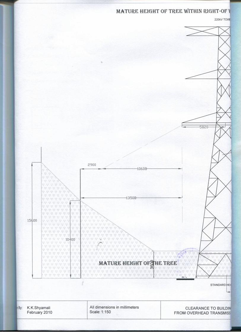
MATURE HEIQHT OF TREE WITHIN RMHT-QF W 220kV T0V4
15600
10400
2900 40608-
43508-
MATURE HEIGHT QF§fHE TREE ml
By: K.K.Shyamali February 2010
All dimensions in millimeters Scale: 1:150
CLEARANCE TO BUILDINI FROM OVERHEAD TRANSMISS
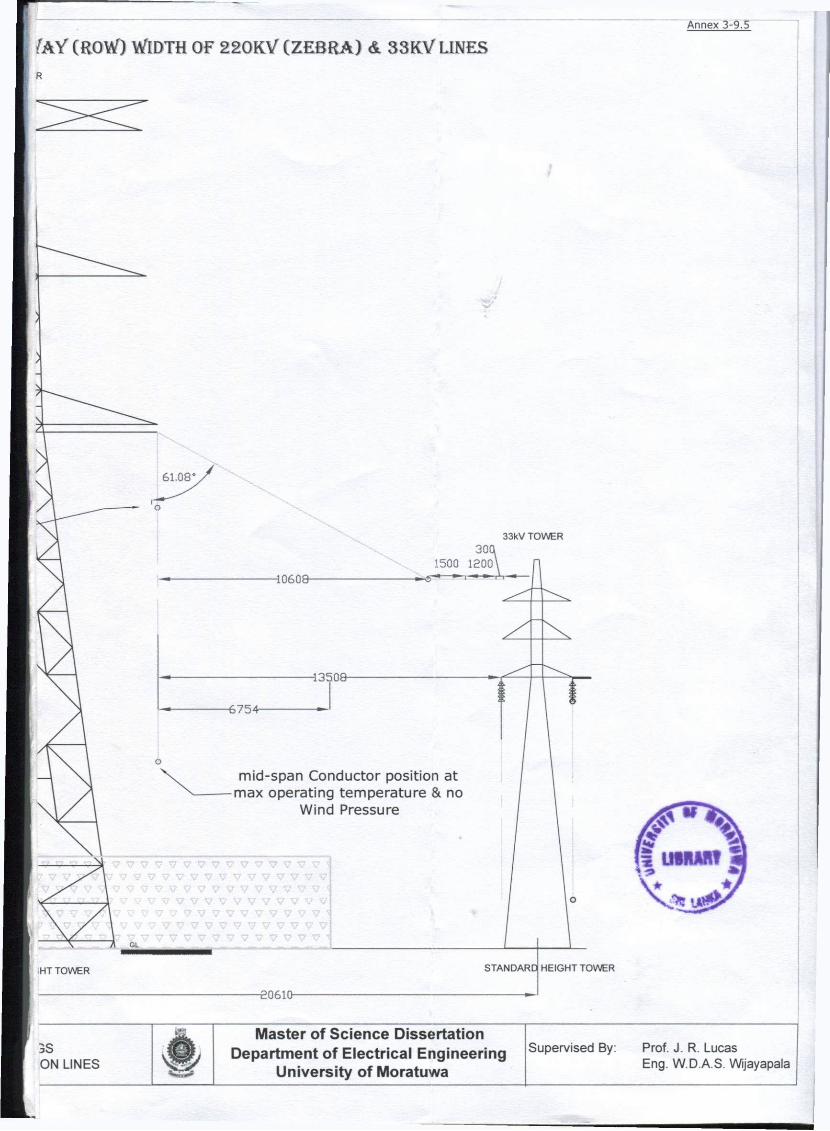
J A Y ( R O W ) W I D T H O F 2 2 0 K V ( Z E B R A ) & 3 3 K V L I N E S R
Annex 3-9,5
10608
33kV TOWER
13508
GL
n TOWER 20610-
mid-span Conductor position at max operating temperature & no
Wind Pressure
STANDARD HEIGHT TOWER
3S ON LINES
Master of S c i e n c e Dissertation Department of Electr ical Engineering
University of Moratuwa
Supervised By: Prof. J. R. Lucas Eng. W.D.A.S. Wijayapala

Annex 3-10
Typical Right-Of-Way (ROW) width defined in "Design Manual for High Voltage
Transmission Lines" is shown in following table. The width of a right-of-way depends
on the voltage of the line and the height of the structures. Please note that this is
based on H-Frame Towers. Therefore, the length of cross arm can be different than
the Lattice-style transmission structures which are used in CEB.
T A B ! : . > : T Y P I C A L R I G H T - O l - \ \ A \ ttlDIJiS
Nominal Line-to-Line Voltage in kV
69 115 138 161 230
ROW Width, ft. 75-100 100 100150 100*150 125 200

The following figure show that another H-frame tower which the specified ROW
125-200ft.
t

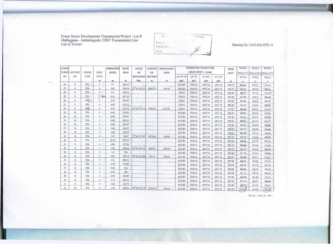
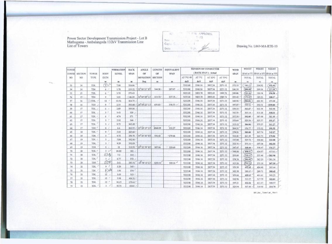
I RECOMMENDED FOR APPROVAL Power Sector Development Transmission Project - Lot B ! WITH COMMENTS Mathugama - Ambalangoda 132kV Transmission Line T~>v.mission Design Branch List of Towers 'o/ lon Electricity Board j Drawing No. L069-MA-RTE-10
: Dae >7/*l/'l %\fi.Jr.. . j
TOWER FORMATIOl* HACK ANGLE LENGTH EQUIVALENT TENSION OF CONDUCTOR WIND w H G i n WIGHT MKHT T o w n SECTION TOWER liODY LEVEL SPAN OF OF SPAN ( BACK SPAN ) - Actual SPAN SPAN al f t Sl'AN al -12'f SPAN 11 75"C
NO NO TYPE EXTN DEVIATION SECTION AT7°C+W AT7»C AT3TC AT 75"C TOTAL TOTAL TOTAL in m m Dtc in m tut daN d»N d»N m ni m m
1 TDT 1) 16.91 5055,00 3803,78 2893.03 1989.74 69.25" .139.61 ' 122.76 106.05 2 1 TD3 J 6 - 681 138.49 ' 22° 30' 54" RT 138.49 138.49 5055.00 3803.78 2893.03 1989.74 219.76 160 30 175.49 190J5 J 2 TD6 - 6 1 5.24 301.03 • 44"34'04"I.T 301.03 301.03 5212.80 3.346,16 283734 2271.12 284,44 •
324.73 - 314 13 303.82 .. 4 3 TLX. 0 y 5.47 267.84 ' 43* 43'17" LT ' 267,84 267.84 5055.00 3803.78 2893.03 1989.74 273.53 204.95 ' 219 85 234.95 5 4 TDI. 3 4.79 279,21 5212.80 3346 16 2837.34 2271.12 304.73 325.52 122 35 11884 6 4 TDI. 3 4.25 330.24 * 5212.80 3346.16 2837.34 2271.12 326 86 328.48 128 24 127.96 7 4 y
TDL 3 ' 3.47 323.48 ' 5212.80 3346.16 2837.34 2271.12 375.38 (22 76. >2! 16 323.60 8 4 TDL / 3 * 3.09 327.27 > 0 5212,80 3346.16 2837,34 2271.12 337.20 ' 338.63 338 41 .138.17 9 s TDL - 3 * 2.45 347.13 ' 5212.80 3346.16 2837.34 2271.12 359,71 308.34'' 316.16 324.85 10 3 TDI. / n < 1.91 372.29 521280 3346 16 2837,34 2271.12 324.00 ' 395.93 384.99 372.82 11 s
11)1. 9 "* 1.69 275.71 - 521280 3346.16 2837 34 2271.12 315.98 * 346.H5 y 342.15 336.93
12 5 TDI ' 0 ' 1.27 356.25 - ' ll°39'46"l.T 2611.58" 331.09 5212.80 3346.16 2837.34 2271.12 299.17 236.63' 246.14 256.72 13 6 TDL 0 ^ i n 242.08 ' 5212.80 .3346 16 2837.34 2271.12 281.81 - 276.57, 277.37 278.26 14 6 TDL , 3 * 1.03 321.53" 5212 80 3346,16 VB7M 2271.12 309.70 ' 323.30 321.23 318.93 15 i TDL ' J ' 0.87 297.86 521280 3346.16 2837.34 2271.12 313.84 275.06 280.96 287.S2 1<J 6 TDI 9 0.81 329,82 - 0 ' 1191,29 303.50 5212,80 3346,16 2837,34 2271.12 372,00 425.20 417,11 408 11 17 7 TDL 6 * 0.73 414 18 5212,80 3346 16 2837.34 2271.12 139 19 384 9 5 - 381,03 376.67 18 7 TDL * o-* 0.72 304.2 - 5212.80 3346 16 2837,34 2271.12 31424 ' 190 34 ' 209 18 230.15 19 7 TD3 3 10.53 324.28 3 o V 4 7 " R T 1042.66 357.56 5212,80 3346.16 2837.34 2271,12 345 27 467.42 448.85 428 18 20 1 TDI. 6 |« 0.6 366.26' 5212.80 3346.16 2837.34 2271.12 35961 30079 309 74 319.69 21 t TDL £_£ 0.«5 352.95 5212.80 3346 16 2837 34 2271,12 353 27 389.66 384 13 377.97 22 1 TDI. 6 £ 0.95 )53 <8 5212,80 3346 16 2837.34 2271.12 359.37 - 143 11 34575 348.47 23 1 TDL * ' 0.76 365.16 t 5212.80 3346.16 2837 34 2271,12 355.08 ' 336 36- 339.20 342J7 14 K
8
TDL 9 ' 0.67 34J - 3212,80 3346.16 2837.34 2271,12 35403 406.21 391 28 389.45 25 8 TDL 3 * 0.67 363.05 - 5212.80 3346.16 2837 1-1 3271 12 355.62 102.87 110 89 319.82
MA Line _ Tnwer list _ Rev 1
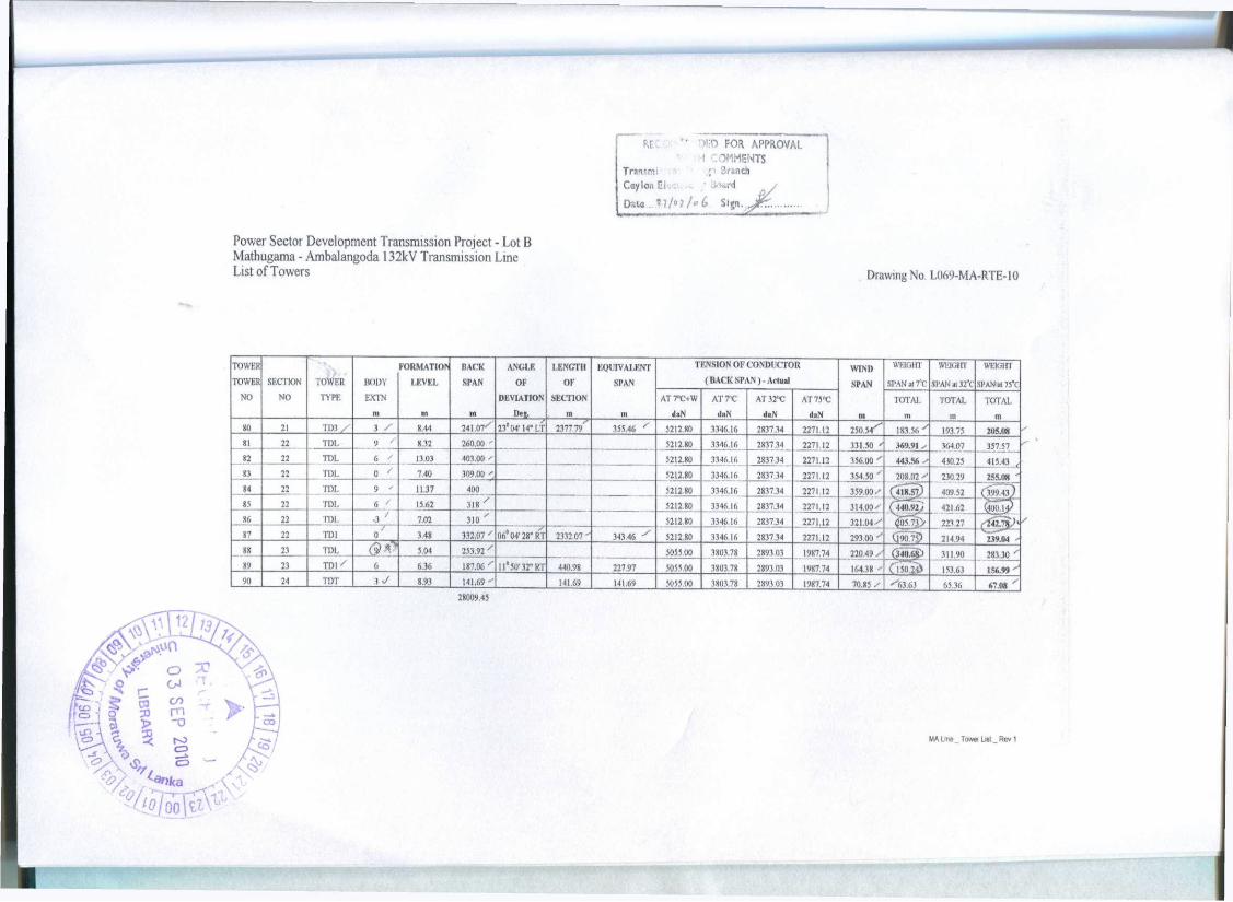
Power Sector Development Transmission Project - Lot B Mathugama - Ambalangoda 132kV Transmission Line List of Towers
r Tranm; Coylon C; Data
Drawing No. L069-MA-RTE-10
Towra FORMATION* BACK ANGLE LENGTH EQUIVALENT TENSION OF CONDUCTOR WIND WBKJHT WEIGH! WEIGHT TOWER SECTION TOWER BODY LKVEL SPAN OE OF SPAN (BACK SPAN) - Arloal SPAN SPAN >i re. SPAN al 12*C SPAN al 75*C
NO NO TYPE EXTN DEVIATION MICTION AT7°CtW AT7°C AT32"C A T 7 5 X TOTAL TOTAL TOTAL m • in D»s. tn in daN daN daN daN in in in m 26 t TDI. • 6 ' 0.7 348.19 " 5212.80 3346.16 2837.34 2271.12 328.37_ 36133 359.71 ' 353.45
27 8 TD6 0 3.93 308.54 .. 37"36' 16" LT 2802.73 - 351.61 5212.80 3346.16 2837.34 2271.12 13267 - 298.25 303.48 309.31 28 9 TDL -
6 S 0.6 356.79.. 5212.8 3346.16 2837.34 2271.12 346.98 •-382.77 i
377.33 371.27--29 9 TDL '
3 . ft 0.35 337.16--- 5212.8 3346.16 2837.34 2271 12 287.07. 241.88 ' 248.75 256.38 30 9 TDL 3 3.18 236.87, 5212.8 3346 16 2837.34 2271.12 245.00 ' 315.41 304.70 291.79 ' 31 9 TDL 0 0.68 253.13 , 5212,8 3346.16 2817.34 2271 12 285.96 ' ' 202.22 " 214 96 229.13 ' 32 9 TH$ 6 0.52 318.78 12"32'55"I.T 1502.73- 311.33 5212.8 3346 16 283734 2271.12 317.87 ' ' 355.38 349.67 343.32 •• 33 10 TDL , 6 f 0.64 316.95 - 5212.80 3346.16 2837.34 2271.12 320.41- 3S9.67 . 353.70 347.06 34 10 TDL _ 0 , ' 0.68 323.86 5212 80 3346.16 2837.34 2271.12 273 10 206 41 216 55 227.83 33 10 TDL
3 ji 0.68 222.33 5212,80 3346.16 2837.34 2271.12 27830 305.51 301 37 296.77 36 to TDL 3 / 0.84 334.27 / 5212,80 3346.16 2837.34 _ 2271.12 335 30 134.93 - 334 99 335.05 37 10 TDL 3 ' 1.06 336.33 5212.80 3346.16 2837.34 2271.12 34843 338 37 339 90 341.60 38 10 TDL 1/ 3.03 360.52 5212.80 3346.16 2837.34 2271 12 31961 361.49 355.12 4 348.04 • 39 10 TD6 0 • 1.97 278.7 57° 58'37" RT 2172.96 . 318.69 y 5212.80 3346.16 2837.34 2271.12 275.73 158 19 ' 176.06 195.95 40 11 TDL - 3 * 10.33 272^5 521580 3346.16 2837.34 2271.12 245.22 , 336.62.. 322.72 307.26 ' 41 11 TDL 6 * 6.88 217.69 ' 5212.80 3340.16 2837.34 2271.12 283.56 329.68- 322.66 ,114.86 l 42 11 TD3 3 .- 1.45 349.43 27°03'43" LT 839.87 295.37 5212.80 3346.16 2837.34 2271.12 350.72 2S3.94-" 294.10 305J9 ' 43 12 TDI 6 1.2 352 5212 80 3346.16 2837.34 2271,12 336 06 311.70^- 315.41 319.53 / 44 12 TD3 9 4.43 320.12' 28'50'24" RT 672.12 337.19 5212.80 3346.16 2837.34 2271.12 309.13 372.40 - 362.77 352,07 ' 43 13 TDL , » •' 1.21 298 13 5212.80 3346.16 2837.34 2271,12 327.00 342.14 , 3)9.83 337.27 -46 13 TDL 3 0.79 355.87 5212,80 3346.16 2837.34 2271.12 354.94 / 299.26 x 307.73 317.15 47 13 TDL 6 '.; 0.83 354 ' 521280 3346.16 2837.34 2271 12 329.00 346.06 343.47 340.58 / 48 13 TDL 6 0.96 304 5212,80 3346.16 2837.34 2271.12 352.44 ' 337.53 * 339.79 342J2 ,-' 49 13 TDL 9 • 0.99 400.87 T 521280 3.346.16 2837.34 2271.12 JJJ.00 410.30 401.89 .192.53 - ' 50 13 TDL 3 ' 1.15 309.13 5212,80 3346.16 2837.34 2271.12 327.45 " 235.53^- 249.51 265.06 51 13 TDL 9 ' 3.8] .345.77 5212.80 3346 16 28.17.34 2271.12 3L5JO^
3(14,74-410.79- 413,22 393.65 -'
52 13 TDI 3 1.22 284.62 . 09" 58'07" LT 2652.39" 337.64 . 5212,80 3346.16 2837.34 2271.12 3L5JO^ 3(14,74- (1l98.0<3 214.28 i'232J3)
MA Line _ Tower List _ Rev 1
Power Sector Development Transmission Project - Lot B Mathugama - Ambalangoda 132kV Transmission Line List of Towers Drawing No. L069-MA-RTE-10
TOWER FORMATION BACK ANGLE LENGTH EQUIVALENT TENSION OF CONDUCTOR WIND WEIGHT WEIGHT WEIGH! TOWER SECTION TOWER BODY LEVEL SPAN OF OF SPAN (BACK SPAN ) - Aclual SPAN SPAN al TC SPAN a yfv SPAN al 75'C
NO NO TYPE EXTN DEVIATION SECTION AT7°C+W AT7°C AT 3 2 X AT75°C TOTAL TOTAL TOTAL m nt m Dej in m daN daN daN daN m nt in in
53 14 TDL 7.98 324.86 " 5212 811 3346.16 2837.34 2271 12 272 19 i 346.17 334.92 / % .322.411 54 14 TD6 6 1.78 219.52 52" 08'31" RT 544.38 - 287.07 5212.80 3346.16 2837.34 2271.12 246.58 200.98 209.24 217.98 • 55 IS TDL 6 ' 3.82 273.63 5055.00 3803.78 2893.03 1989.74 209.86 1 84 46 190.54 196.58 56 IS TD6 9 .3.01 146.09 34'03'58"LT 419.72 237 1 5 . 5055.00 3803.78 2893.03 1989.74 225.42 (17983"' 183.22 188.17 » 57 16 jtTDL * 12 ' 12.56 304.75 5212 81! 3346.16 2837.34 2271.12 349.92 ' (504.86) 481 10 455.08 ... 58 16 TD3 • 9 ' 2.55 395.08 ' 24*34"'22" LT 699.83 358 55 - 5212.80 3346.16 2837.34 2271.12 397.07 - MJTo'-- 350.51 359.8(1 59 17 TDL - 6 t 2,89 399.06 5212.80 3346.16 2837.34 2271 12 359.53 ' 361.67 - 361.34 360.98 60 17 TDL 3 ' 3.43 320 <" 5212.80 3346.16 2837.34 2271.12 .145.50 305,14 - 311 28 318.1! 61 17 TDL ' 6 ' 4.74 371 ' 5212 80 3346.16 2817.34 2271.12 357.50 • 392.85 387.48 381.49 -67 17 TDL ' 3 •? 5.92 344 / 5212.80 3346.16 2837.34 2271,12 353.64 •* 320.54 - 325.57 331.17
_ 63_ 17 T D L / 3 ' 9.75 363.28 5212.80 3346.16 2837.34 2271.12 313 12 ' 384.06 373.27 361.27 64 17 xm - 0 • 66 262.95 25*24'15" LT 2060.29 351.27 5212.80 3346.16 2837.34 2271.12 264.31 ' 156.77 - 173.12 191.32 65 l i TDL ' 9 ' 5.05 265.66 5212.80 1346 16 2837.34 2271.12 278.21 " 383.80 367.74 349.87 66 18 TD6 ' 3 4.52 290.76 59s 26'36" RT 556.42 -279.06 5212.80 3346.16 2837 34 2271,12 316.41 261.39 269.75 279.06 67 19 TDI. 3 5.84 342.06 - 5212.80 3346.16 2837 31 2271.12 337.08 ' 329.72 • 330 84 332.08 68 19 TDL 3 ' 8.29 332.09 ' 5212.80 3346.16 28.17.34 2271.12 322.51 * 293.10 ' 297.58 302.55 69 19 TD3 0 18 312.93 23s 52'59" RT 987.08 32969 5212.80 3346.16 2837.34 2271.12 347.47 3611.44 358.47 356.27 , 70 20 TDL ' 3 20.(2 382 - 5212.80 3346.16 2837.34 2271.12 - 348.00 | 450.57* 434.97 41761 -71 20 TDL ' 7.2 314 - 5212.80 3346 16 2837.34 2271.12 293.00 V —R- 255.40 • 262.90 72 20 T D L '
3 gj 6.77 272 521280 3346 16 2837.34 2271 12 278.76 2S2.H5 » 282 23 -281 .54 73 20 11)3 ' s * 2.61 285.51"'' 1^58'12'LT 1253.51 322.16 * 5212 80 3346.16 2837.34 2271.12 315.26 255 10 267.10 .-74 5jf . , ; TDI. " 9 ' 3.29 345 ' 5212.80 3346.16 2837.34 2271.12 339.50 412.45 - 404 40 395.44 75 21 TDI. ' 1.06 374 "" 5212 80 3346.16 2837.34 2271.12 343.50 280.07 * 289 71 300.45
21 TDL 12 ' 5.69 313 ' 5212.80 3346.16 2837.34 2271 12 339.66 409.13 ' 401.61 393 23 77 21 TDL ' 12 ' 5.98 406.31 ' 5212 80 3346.16 2837.34 2271.12 3 4 2 % 31327 ' 31779 322.81 78 21 TDL 12 * 10.15 27961 5212.80 3346 16 2837.34 2271.12 349.21 422.52 411.37 398 97 79 21 TDL ' 3 / 10.71 418.8 ' 521280 3346 16 2837 34 2271.12 329.94 307 49 HO 90 314.70
MA Line Tower Lie!Rev 1
fj . '• >«"> FOR APPROVAL I COMMENTS
Transmi • j t Branch Ceylon Ei. i ' ,><wd
Oata . . .M/•?/<»£ Sign.
Power Sector Development Transmission Project - Lot B Mathugama - Ambalangoda 132kV Transmission Line List of Towers Drawing No. L069-MA-RTE-I0
TOWER TOWER
NO SECTION
NO TOWER
TYPE BODY EXTN
m
FORMATION LEVEL
m
HACK SPAN
m
ANGLE OF
DEVIATION
LENGTH OF
SECTION m
EQUIVALENT SPAN
m
TENSION OF CONDUCTOR ( BACK SPAN ) - Actual
WIND SPAN
m
WEIGHT SPAN«7*C
WEK3HT SPAN al 32"0
WEIGHT SPAN M 7S*C
TOWER TOWER
NO SECTION
NO TOWER
TYPE BODY EXTN
m
FORMATION LEVEL
m
HACK SPAN
m
ANGLE OF
DEVIATION
LENGTH OF
SECTION m
EQUIVALENT SPAN
m AT7°C+W
daN AT7T
daN AT32"C
daN AT75°C
daN
WIND SPAN
m TOTAL
m TOTAL
in TOTAL
m 80 21 11)3 / 3 / 8.44 241.07^ 23° 04'14" LT 2377.79 355.46 5212.80 3346.16 2837 34 2271.12 250.54^" 183.56 y 193.75 205.08 81 22 TDI, 9 / 8.32 260.00 ' 5212.80 3346.16 2837.34 2271.12 331.50 ' 369.91 «. 364.07 357.57 82 22 TDL 6 if 13.03 403.00 ' 5212.80 3346.16 2837.34 2271.12 356.00 ' 443.56 s 430.25 415.43 , 8} 22 TDL 0 < 7.40 309.00 _^ 5212.80 3346.16 2837.34 2271.12 354.50 ' 208.02 * 230.29 255,08 ' 84 22 TDL 9 * 11.37 400 5212.80 3346.16 2837.34 2271.12 359.00."
( 4 4 0 . 9 2 ^ 409.52 421.62
( M 9 4 3 ) 85 22 TDL 6 ' 15.62 318 ' 5212,80 3346.16
3346.16 2837.34 2271.12 314.00' ( 4 4 0 . 9 2 ^
409.52 421.62
( M 9 4 3 )
86 22 TDL • 3 / 7.02 310 * 5212,80 3346.16 3346.16 2837.34 2271.12 321,04^ §?-_l> 223,27
87 22 TDI 7 0
3.48 3.12.07 ' 06* 04'28" RT 2.132.07 .34.346 5212,80 3346.16 2837.34 2271.12 293.00 ' Q'90,75) 21494 239.04 ' 88 23 TDL 5.04 253.92 / 5055.00 3803.78 2893 03 1987.74 220,49 y 04O.68> 311.90 283.30 '' 89 23 TDI / 6 6.36 187.06 '" 11°5IH2"RT 440.98 227 97 5055.00 3803,78 2893.03 1987.74 164.38 ,=•«<, ( 150.24J 153.63 156.99 90 24 TOT 3 J 8.93 141.69 141.69 141.69 5055.00 3803.78 2893.03 1987.74 70.85 / ""'63.63 65.36 67.08 '
28009.45
MA Line Towei List „ Rev 1
Recommended