INSTRUCTIONS
BX61MOTORIZED SYSTEM
MICROSCOPES
A X 7 6 1 1
This instruction manual is for the Olympus Motorized System Microscopes Models BX61 and BX62.To ensure the safety, obtain optimum performance and to familiarize yourself fully with the use ofthis microscope, we recommend that you study this manual thoroughly before operating the micro-scope. Retain this instruction manual in an easily accessible place near the work desk for futurereference.

BX61
CONTENTS
4-5
6-7
8-21
IMPORTANT — Be sure to read this section for safe use of the equipment. —
1 NOMENCLATURE
2
3 USING THE CONTROLS
TRANSMITTED LIGHT BRIGHTFIELD OBSERVATION PROCEDURE
3-1 Base ................................................................................................................................................................................................................. 8-10
3-2 Focusing Block ............................................................................................................................................................................. 11-12
1 Voltage Indication 2 Transmitted/Reflected Light Switch
3 Light Preset Switch 4 Using the Filters
3-3 Stage ........................................................................................................................................................................................................... 13-15
3-4 Observation Tube ..................................................................................................................................................................... 16-18
3-5 Condenser .......................................................................................................................................................................................... 19-20 1 Centering the Condenser 2 Compatibility of Objectives and Condensers
1 Adjusting the Interpupillar Distance 2 Adjusting the Diopter
3 Using the Eye Shades 4 Using the Eyepiece Micrometer Disk
5 Selecting the Light Path of the Trinocular Tube
6 Adjusting the Tilt
1-3
Correct assembly and adjustments are indispensable to allow the microscope manifest its full performance. If youare going to assemble the microscope by yourself, please read chapter 7, “ASSEMBLY” (pages. 29 to 32).
ASSEMBLY — See this section for the replacement of the light bulb. —
3-6 Immersion Objectives .................................................................................................................................................................. 21
3-7 Objectives with Correction Collar .............................................................................................................................. 21
4 TROUBLESHOOTING GUIDE
5 SPECIFICATIONS
6 OPTICAL CHARACTERISTICS <<UIS2 (UIS) Series>>
7
PROPER SELECTION OF THE POWER SUPPLY CORD ................................................................. 33-34
22-24
25-26
27-28
29-32
1 Replacing the Focus Adjustment Knob 2 F/C button
3 Stage UP/DOWN Buttons 4 Stage Escape Button
1 Placing the Specimen 2 Adjusting the X/Y-Axis Knob Tension
3 Rotating the Stage 4 Adjusting the Stage Height
NOTE: This equipment has been tested and found to comply with the limits for a Class A digital device,
pursuant to Part 15 of the FCC Rules. These limits are designed to provide reasonable protection
against harmful interference when the equipment is operated in a commercial environment. This
equipment generates, uses, and can radiate radio frequency energy and, if not installed and used in
accordance with the instruction manual, may cause harmful interference to radio communications.
Operation of this equipment in a residential area is likely to cause harmful interference in which case
the user will be required to correct the interference at his own expense.
FCC WARNING: Changes or modifications not expressly approved by the party responsible for compliance
could void the user’s authority to operate the equipment.
This device complies with the requirements of directive 98/79/EC concerning in vitro diag-nostic medical devices. CE marking means the conformity to the directive.

1
BX61
Manual Name Main Contents
IMPORTANT
Each of these microscopes employs a UIS2/UIS (Universal Infinity System) optical design, and shouldbe used only with modules designed for the BX2 series (which belong to the Olympus BX seriesmicroscopes) and objectives/eyepieces for the UIS series.For the applicable module, please consult Olympus or the catalogues. Less than optimum perfor-mance may result if inappropriate accessories are used.
Configuration of Instruction ManualsSince these microscopes are expandable to a variety of systems, separate instruction manuals are providedso that the user has to read only the manuals according to the user’s own system.
BX61 Transmitted light brightfield observation procedure
BX-UCB/U-HSTR2 Functions of the Control Box (incorporating the power supply)and Hand Switch
BX2 Software for PC (CD-ROM) Methods of PC Control of Functions
BX-RFAA Reflected light fluorescence observation procedure
BX-RLAA Reflected light brightfield/darkfield observation
U-UCD8A Motorized universal condenser
U-FWT/FWR/FWO Motorized filter wheels
SAFETY PRECAUTIONS
1. After the equipment has been used in an observation of a specimen thatis accompanied with a potential of infection, clean the parts coming incontact with the specimen to prevent infection. · Moving this product is accompanied with the risk of dropping the
specimen. Be sure to remove the specimen before moving thisproduct.
· In case the specimen is damaged by erroneous operation, promptlytake the infection prevention measures.
· The product becomes unstable if its height is increased by an accessorymounted on it. In this case, take anti-toppling measures to prevent thespecimen from being dropped when the product topples down.
2. Install the microscope on a sturdy, level table or bench so as not to blockthe air vents on the underside of the base.Do not place the microscope on a flexible surface, as this could result inblocking the air vents and cause overheating or a fire.
3. If a foreign object is caught during motorized focusing operation, therewill be an error in the focusing block and the motorized focusing opera-tion will be suspended.Recovery procedure
· If there is no error in motorized operation, the caught object can beremoved by turning the focusing knob.
· If there is an error in motorized operation, the focusing knob becomesinoperable. Disassemble the relevant modules to remove the caughtobject. Replace the relevant modules afterward.
· Turn off the power and then on again. The system will restart unlessthere is a malfunction in the motor.
4. To activate temporary stop during focusing operation, turn the focusingknob (or dial) on the microscope frame (in either direction) or press any ofthe FOCUS control buttons ( , , F/C and ESC) (except during PCcommunication).When the main switch of the BX-UCB control box is set to “ I ” (ON), thefocusing operation starts automatically as part of initialization (this opera-tion consists of temporary lowering and then returning to the originalposition of the stage). If any of the operations mentioned above is per-formed, an emergency stop will also occur. In this case, set the mainswitch to “ ” (OFF) and then “ I ” (ON) again.
2
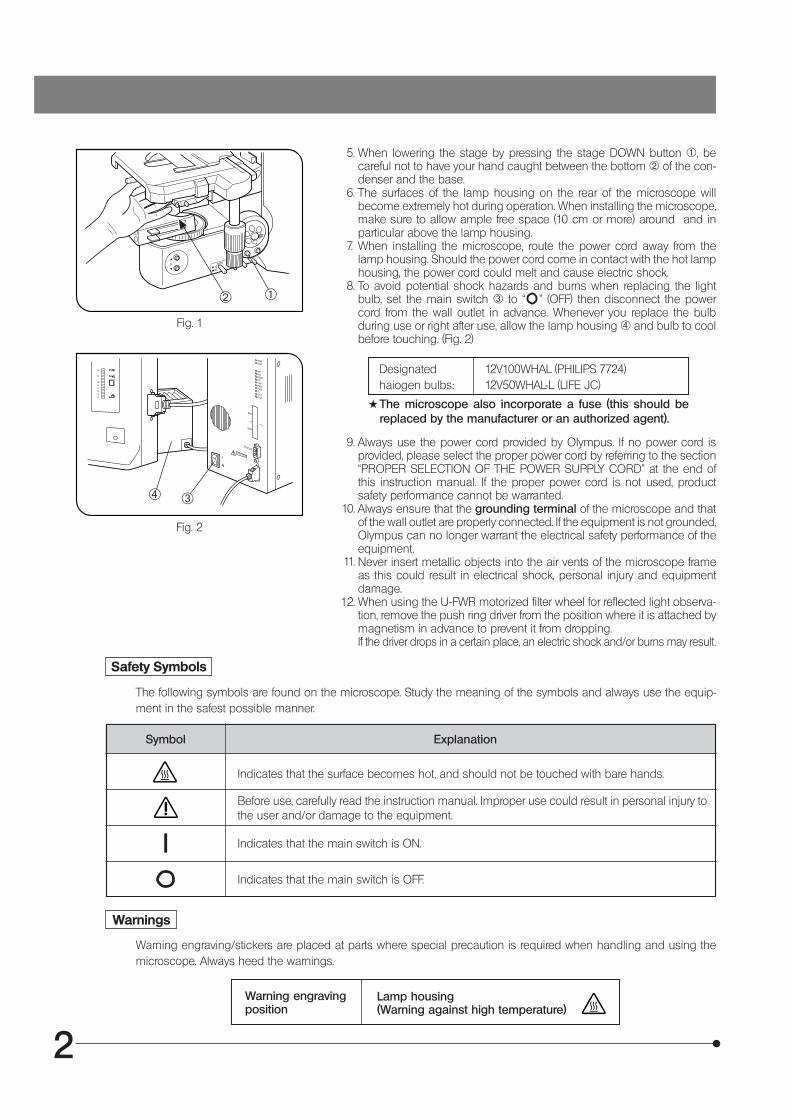
Designatedhaiogen bulbs:
12V100WHAL (PHILIPS 7724)12V50WHAL-L (LIFE JC)
#The microscope also incorporate a fuse (this should bereplaced by the manufacturer or an authorized agent).
5. When lowering the stage by pressing the stage DOWN button @, becareful not to have your hand caught between the bottom ² of the con-denser and the base.
6. The surfaces of the lamp housing on the rear of the microscope willbecome extremely hot during operation. When installing the microscope,make sure to allow ample free space (10 cm or more) around and inparticular above the lamp housing.
7. When installing the microscope, route the power cord away from thelamp housing. Should the power cord come in contact with the hot lamphousing, the power cord could melt and cause electric shock.
8. To avoid potential shock hazards and burns when replacing the lightbulb, set the main switch ³ to “ ” (OFF) then disconnect the powercord from the wall outlet in advance. Whenever you replace the bulbduring use or right after use, allow the lamp housing | and bulb to coolbefore touching. (Fig. 2)
Symbol Explanation
The following symbols are found on the microscope. Study the meaning of the symbols and always use the equip-ment in the safest possible manner.
Indicates that the surface becomes hot, and should not be touched with bare hands.
Before use, carefully read the instruction manual. Improper use could result in personal injury tothe user and/or damage to the equipment.
Indicates that the main switch is ON.
Indicates that the main switch is OFF.
Warning engraving/stickers are placed at parts where special precaution is required when handling and using themicroscope. Always heed the warnings.
Warning engravingposition
Lamp housing(Warning against high temperature)
l
Safety Symbols
Warnings
9. Always use the power cord provided by Olympus. If no power cord isprovided, please select the proper power cord by referring to the section“PROPER SELECTION OF THE POWER SUPPLY CORD” at the end ofthis instruction manual. If the proper power cord is not used, productsafety performance cannot be warranted.Always ensure that the grounding terminal of the microscope and thatof the wall outlet are properly connected. If the equipment is not grounded,Olympus can no longer warrant the electrical safety performance of theequipment.Never insert metallic objects into the air vents of the microscope frameas this could result in electrical shock, personal injury and equipmentdamage.When using the U-FWR motorized filter wheel for reflected light observa-tion, remove the push ring driver from the position where it is attached bymagnetism in advance to prevent it from dropping.If the driver drops in a certain place, an electric shock and/or burns may result.
11.
³|
Fig. 2
Fig. 1
@²
12.
10.
3
BX61
Fig. 3
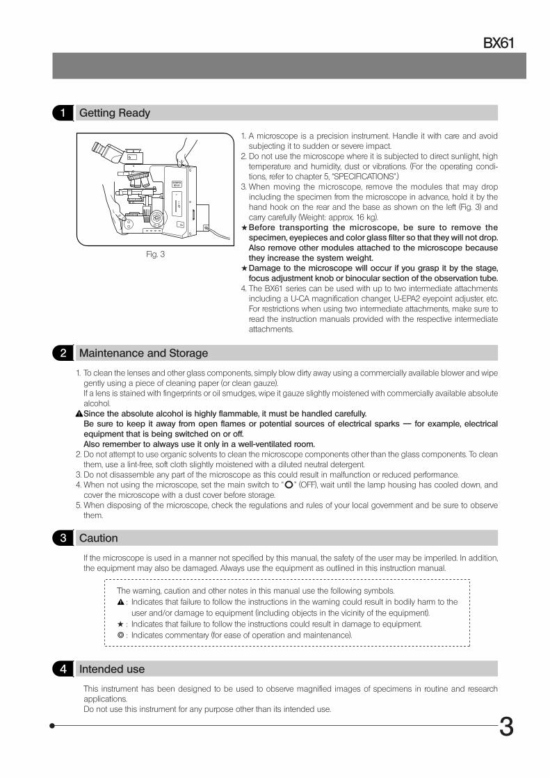
1 Getting Ready
1. A microscope is a precision instrument. Handle it with care and avoidsubjecting it to sudden or severe impact.
2. Do not use the microscope where it is subjected to direct sunlight, hightemperature and humidity, dust or vibrations. (For the operating condi-tions, refer to chapter 5, “SPECIFICATIONS”.)
3. When moving the microscope, remove the modules that may dropincluding the specimen from the microscope in advance, hold it by thehand hook on the rear and the base as shown on the left (Fig. 3) andcarry carefully (Weight: approx. 16 kg).
#Before transporting the microscope, be sure to remove thespecimen, eyepieces and color glass filter so that they will not drop.Also remove other modules attached to the microscope becausethey increase the system weight.
#Damage to the microscope will occur if you grasp it by the stage,focus adjustment knob or binocular section of the observation tube.
4. The BX61 series can be used with up to two intermediate attachmentsincluding a U-CA magnification changer, U-EPA2 eyepoint adjuster, etc.For restrictions when using two intermediate attachments, make sure toread the instruction manuals provided with the respective intermediateattachments.
2 Maintenance and Storage
1. To clean the lenses and other glass components, simply blow dirty away using a commercially available blower and wipegently using a piece of cleaning paper (or clean gauze).If a lens is stained with fingerprints or oil smudges, wipe it gauze slightly moistened with commercially available absolutealcohol.Since the absolute alcohol is highly flammable, it must be handled carefully.Be sure to keep it away from open flames or potential sources of electrical sparks –– for example, electricalequipment that is being switched on or off.Also remember to always use it only in a well-ventilated room.
2. Do not attempt to use organic solvents to clean the microscope components other than the glass components. To cleanthem, use a lint-free, soft cloth slightly moistened with a diluted neutral detergent.
3. Do not disassemble any part of the microscope as this could result in malfunction or reduced performance.4. When not using the microscope, set the main switch to “ ” (OFF), wait until the lamp housing has cooled down, and
cover the microscope with a dust cover before storage.5. When disposing of the microscope, check the regulations and rules of your local government and be sure to observe
them.
3 Caution
If the microscope is used in a manner not specified by this manual, the safety of the user may be imperiled. In addition,the equipment may also be damaged. Always use the equipment as outlined in this instruction manual.
The warning, caution and other notes in this manual use the following symbols.: Indicates that failure to follow the instructions in the warning could result in bodily harm to the
user and/or damage to equipment (including objects in the vicinity of the equipment).# : Indicates that failure to follow the instructions could result in damage to equipment.} : Indicates commentary (for ease of operation and maintenance).
4 Intended use
This instrument has been designed to be used to observe magnified images of specimens in routine and researchapplications.Do not use this instrument for any purpose other than its intended use.
4
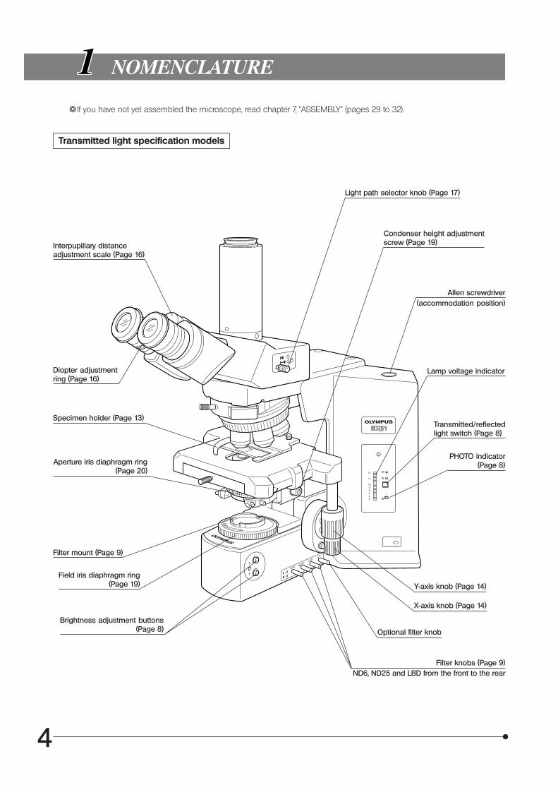
1 NOMENCLATURE
}If you have not yet assembled the microscope, read chapter 7, “ASSEMBLY” (pages 29 to 32).
Transmitted light specification models
Interpupillary distanceadjustment scale (Page 16)
Diopter adjustmentring (Page 16)
Specimen holder (Page 13)
Aperture iris diaphragm ring(Page 20)
Filter mount (Page 9)
Field iris diaphragm ring(Page 19)
Brightness adjustment buttons(Page 8)
Light path selector knob (Page 17)
Condenser height adjustmentscrew (Page 19)
Allen screwdriver(accommodation position)
Lamp voltage indicator
Transmitted/reflectedlight switch (Page 8)
PHOTO indicator(Page 8)
Y-axis knob (Page 14)
X-axis knob (Page 14)
Optional filter knob
Filter knobs (Page 9)ND6, ND25 and LBD from the front to the rear
5
BX61
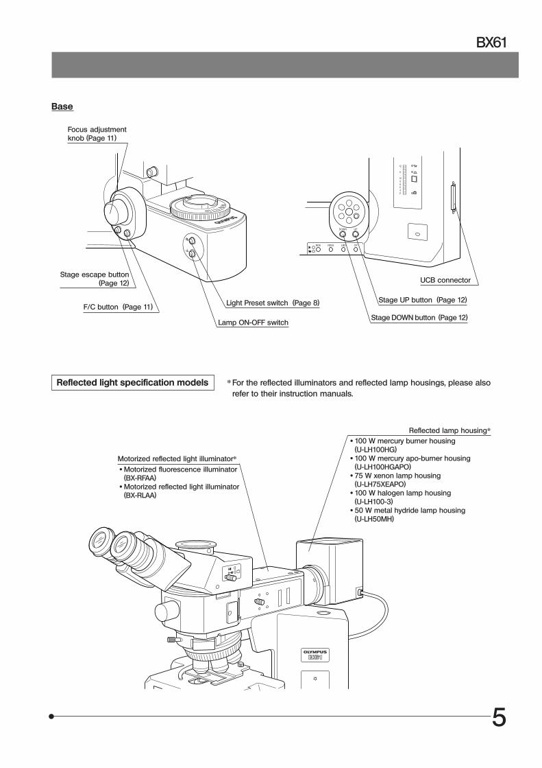
Base
Focus adjustmentknob (Page 11)
* For the reflected illuminators and reflected lamp housings, please alsorefer to their instruction manuals.
Reflected light specification models
UCB connector
Motorized reflected light illuminator*
Stage escape button(Page 12)
F/C button (Page 11) Light Preset switch (Page 8)
Lamp ON-OFF switch
Stage UP button (Page 12)
Stage DOWN button (Page 12)
Reflected lamp housing*
· Motorized fluorescence illuminator(BX-RFAA)
· Motorized reflected light illuminator(BX-RLAA)
· 100 W mercury burner housing(U-LH100HG)
· 100 W mercury apo-burner housing(U-LH100HGAPO)
· 75 W xenon lamp housing(U-LH75XEAPO)
· 100 W halogen lamp housing(U-LH100-3)
· 50 W metal hydride lamp housing(U-LH50MH)

6
TRANSMITTED LIGHT BRIGHTFIELDOBSERVATION PROCEDURE
(Controls Used) (Page)
Set the main switch to “ I ” (ON).@Main switch “ I ” (ON)²Lamp ON-OFF switch ON
Select the transmitted light and adjust thebrightness.
³Transmitted/reflected light switch (P. 8)|Brightness adjustment buttons (P. 8)
Engage the LBD filter in light path. ƒLBD filter knob
Select the light path (when a trinocular tube isused).
…Light path selector knob (P. 17)
Place the specimen on the stage.†Specimen holder (P. 13)‡X/Y-axis knobs (P. 14)
Engage the 10X objective in the light path. ŠRevolving nosepiece button
Bring the specimen in focus. ‰Stage UP/DOWN button, focusadjustment knob
Adjust the interpupillary distance.Adjust the diopter.Adjust the light axis.
‹Binocular tube (P. 16)ŒDiopter adjustment ring (P. 16)™Condenser height adjustment screw (P. 19)šCondenser centering screws (P. 19)
Adjust the aperture iris and field iris diaphragms.›Aperture iris diaphragm ring (P. 20)œField iris diaphragm ring (P. 19)
Engage the objective to be used in the lightpath and bring the specimen in focus.
ŠRevolving nosepiece button‰Stage UP/DOWN button, focus
adjustment knob
Engage the required filters. ŸFilters (P. 9)
Adjust the brightness. |Brightness adjustment buttons (P. 8)
Start observation.
(P. 12)
(P. 12)
7
BX61
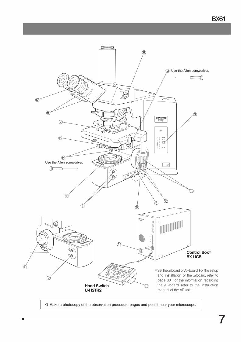
} Make a photocopy of the observation procedure pages and post it near your microscope.
* Set the Z-board or AF-board. For the setupand installation of the Z-board, refer topage 30. For the information regardingthe AF-board, refer to the instructionmanual of the AF unit.
@
Use the Allen screwdriver.
Use the Allen screwdriver.
Control Box*BX-UCB
Hand SwitchU-HSTR2
²
| ƒ
…
†
‡
Š
‰
‰
‹
Œ
™
š
›
œ
Ÿ
³
8
USING THE CONTROLS
3-1 Base
1 Voltage Indication (Fig. 4)
1. Press the Brightness adjustment button @ to increase the voltage andmake illumination brighter.Pressing the button ² makes the illumination darker.
2. The numerals on the left of the lamp voltage LEDs ³ indicate theapproximate voltage.
#The LED may sometimes go out (temporarily) when the motor isdriving. Even in this case, there is no fluctuation in illuminationvoltage.
2 Transmitted/Reflected Light Switch (Fig. 4)
The illumination can be switched between the transmitted light and re-flected light by pressing the transmitted/reflected light switch |.
: Reflected light illumination: Transmitted light illumination
The indicator of the selected illumination lights.
3 Light Preset Switch (Fig. 5)
}The Light Preset switch sets the light intensity voltage to a voltage suit-able for color photography* (the factory default is 9 V) regardless of thecurrent setting of the light intensity adjustment buttons.
* Achieved by engaging the built-in LBD filter.Setting the Desired Brightness (Figs. 4 & 5)1. Press the Light Preset switch ƒ The PHOTO indicator … lights up.2. Press one of the light intensity adjustment buttons @ ² to set the de-
sired brightness.3. Press the Light Preset switch again. The indictor turns off, the brightness
returns to the original brightness but the setting made above is stored inmemory.
4. Hereafter, pressing the Light Preset switch sets the brightness to the in-tensity value set in step 2 above.
#Be sure to set the light intensity voltage back to 9 V when colorphotography is to be performed.
}When the Light Preset switch ƒ is pressed, a note sound (short beep) isgenerated at the 9 V position.
4 Using the Filters (Figs. 6 - 11)
}You can place a filter in the light path with one of the following fourmethods.
· Push in the knob of a built-in filter to engage it in the light path. (Page 9) · Place a filter on the filter mount on the base and engage in the light path.
(Page 9) · Insert a filter in the U-FC filter cassette, attach it on the filter mount and
engage it in the light path by sliding the filter lever. (Page 9) · Insert a filter in the U-FWT filter wheel, attach it on the filter mount and
engage it in the light path by motorized operation (using the PC). (Referto the separate instruction manual.)
Fig. 4
Fig. 5
@²
³
| …
ƒ

9
BX61
Using Built-In Filters (Fig. 6)
Each filter can be engaged into the light path by pressing one of the filterknobs @ to | in. Pressing the button again disengages the filter from thelight path.
Filter Type/Purpose
@ ND6 (Neutral Density filter for light adjustment, transmittance 6%)
² ND25 (Neutral Density filter for light adjustment, transmittance 25%)
³ LBD (for color balancing, daylight filter)
| OP (optional) filter set*
* Ask your Olympus representative to mount the filters.
Mounting a Single Filter (Fig. 7)
A filter with a diameter of 45 mm ƒ can be placed on the filter mount onthe base. If you need to place multiple filters, please purchase the U-FCfilter cassette.
#Even when a filter cassette is used, a filter with thickness of no morethan 3 mm can still be placed on the filter mount.
Using the Filter Cassette (Figs. 8 - 11)
Loading Filters into Filter Cassette}The filter cassette accommodates filters with a diameter of 45 mm and
thickness of 2.7 mm or less.}The filter cassette has two filter levers on the right side and one on the left
side.1. Move all filter levers to the OUT position except for the one belonging to
the slot into which the filter is to be inserted.2. Slide the lever … to the IN position. Make sure that it clicks securely into
place. (Fig. 8)3. Holding the lever in the position shown in Fig. 8, put the filter into the
cassette by inserting it in the direction indicated by the arrow.4. Insert the other two filters in the same manner.
Fig. 6
Fig. 7
Fig. 8
@ ² ³ |
ƒ
…
10
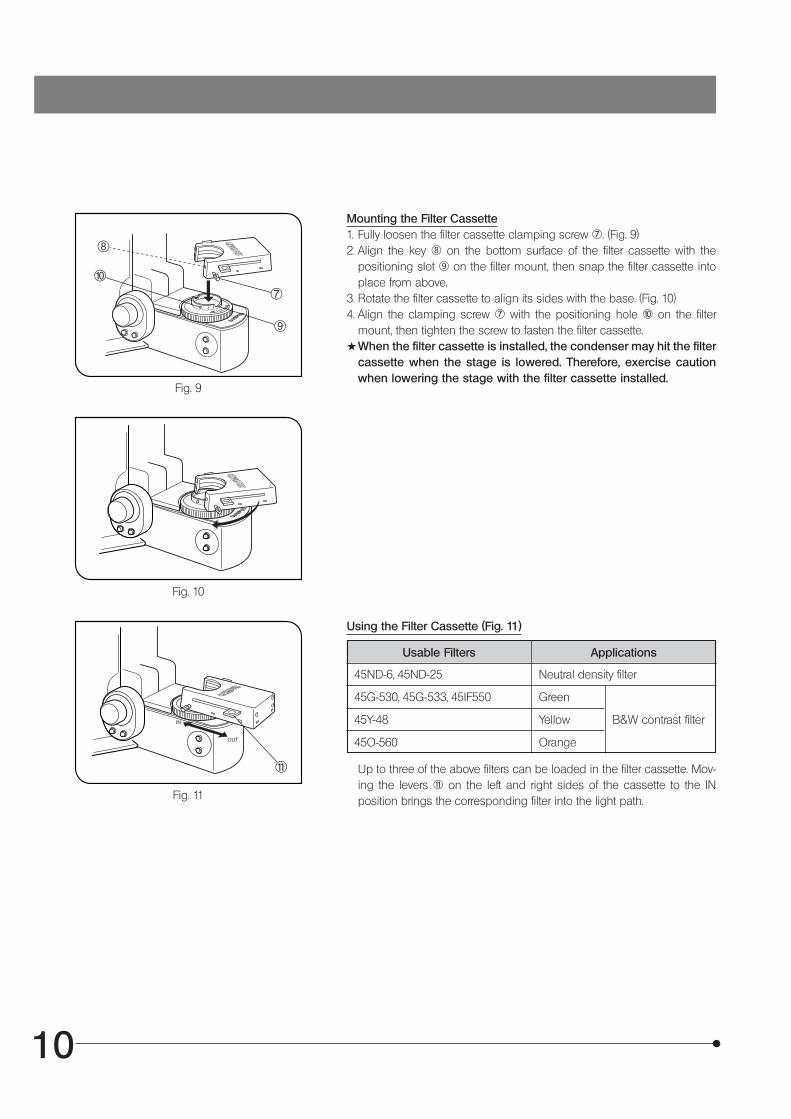
Mounting the Filter Cassette1. Fully loosen the filter cassette clamping screw †. (Fig. 9)2. Align the key ‡ on the bottom surface of the filter cassette with the
positioning slot Š on the filter mount, then snap the filter cassette intoplace from above.
3. Rotate the filter cassette to align its sides with the base. (Fig. 10)4. Align the clamping screw † with the positioning hole ‰ on the filter
mount, then tighten the screw to fasten the filter cassette.#When the filter cassette is installed, the condenser may hit the filter
cassette when the stage is lowered. Therefore, exercise cautionwhen lowering the stage with the filter cassette installed.
Using the Filter Cassette (Fig. 11)
Usable Filters Applications
45ND-6, 45ND-25 Neutral density filter
45G-530, 45G-533, 45IF550 Green
45Y-48 Yellow B&W contrast filter
45O-560 Orange
Up to three of the above filters can be loaded in the filter cassette. Mov-ing the levers ‹ on the left and right sides of the cassette to the INposition brings the corresponding filter into the light path.
Fig. 9
Fig. 10
Fig. 11
†
‡
Š
‰
‹
11
BX61
3-2 Focusing Block
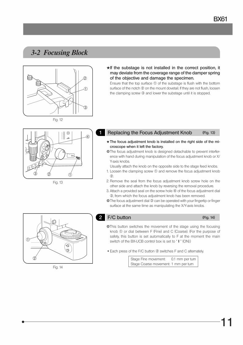
#If the substage is not installed in the correct position, itmay deviate from the coverage range of the damper springof the objective and damage the specimen.Ensure that the top surface @ of the substage is flush with the bottomsurface of the notch ² on the mount dovetail. If they are not flush, loosenthe clamping screw ³ and lower the substage until it is stopped.
1 Replacing the Focus Adjustment Knob (Fig. 13)
#The focus adjustment knob is installed on the right side of the mi-croscope when it left the factory.
}The focus adjustment knob is designed detachable to prevent interfer-ence with hand during manipulation of the focus adjustment knob or X/Y-axis knobs.Usually attach the knob on the opposite side to the stage feed knobs.
1. Loosen the clamping screw @ and remove the focus adjustment knob².
2. Remove the seal from the focus adjustment knob screw hole on theother side and attach the knob by reversing the removal procedure.
3. Attach a provided seal on the screw hole | of the focus adjustment dial³, from which the focus adjustment knob has been removed.
}The focus adjustment dial ³ can be operated with your fingertip or fingersurface at the same time as manipulating the X/Y-axis knobs.
2 F/C button (Fig. 14)
}This button switches the movement of the stage using the focusingknob @ or dial between F (Fine) and C (Coarse). (For the purpose ofsafety, this button is set automatically to F at the moment the mainswitch of the BX-UCB control box is set to “ I ” (ON).)
· Each press of the F/C button ² switches F and C alternately.
Stage Fine movement: 0.1 mm per turnStage Coarse movement: 1 mm per turn
Fig. 12
Fig. 13
Fig. 14
@²³
²
@
²
³
|
@

12
3 Stage UP/DOWN Buttons (Fig. 15)
When lowering the stage, be careful not to have your hand caughtbetween the bottom of the condenser and the base.
· Press the stage UP button @ to raise the stage and press the stageDOWN button ² to lower the stage.
· The stroke is 25 mm. It becomes 14 mm when the U-FWT filter wheel isused.
· The upper limit of stage movement has been set so that the stage stopswithin the coverage range of the damper spring of objective when a slidespecimen (thickness 1.2 mm) is used.
#When observing a metallurgic specimen with thickness above 1.2mm, take care so that the stage does not hit the objective.
4 Stage Escape Button (Fig. 16)
When replacing the specimen, press the stage escape button @. Thestage will lower by 5 mm (in 1 sec.). Pressing the button again returns thestage to the original height.
Fig. 15
Fig. 16
² @
@

13
BX61
3-3 Stage
}The following description deals with biological specimens. When observing a metallurgic specimen, it is more convenientto replace the special stage or slide holder with the stage plate. (For details, refer to the instruction manual for the BX-RLAA.)
1 Placing the Specimen
#The dimensions of the slide glass should be 26 x 76 mm with thick-ness of 0.9 to 1.2 mm, and the cover glass should have thickness of0.17 mm.
#When observing very large specimens, remove the slide holder andplace the specimen directly on the stage.
Microscopy with Double-Slide Holder (Fig. 17)
1. Press the stage DOWN button @ or stage escape button to lower thestage.
2. Open the specimen holder clamping lever ² and place the specimenslides on the stage by sliding each slide from the front.
3. After placing the slides as far as they will go, gently release the clampinglever.
Microscopy with Single-Slide Holder (Fig. 18)
The specimen slide can easily be placed by sliding it into the slide holderfrom the front.
Fig. 17
Fig. 18
Fig. 19
@
²
³
Examining a whole specimenUse one of the thin slide holders listed below that cause less interferencewith the objectives*.· U-HRD-4 · U-HLD-4 · U-HLS-4
* The applicable objectives are ones with 40X or less magnification (exceptApo series).
Using an Oil Immersion ObjectiveAdsorption of immersion oil can cause the specimen to drift. In suchcases, it is recommended to use the optional BH2-SCB-3 specimen clip³ for oil immersion objectives. (Fig. 19)
Using an Oil Immersion CondenserIt may be effective to use the optional U-SVRO (right-hand knob) or U-SVLO (left-hand knob) slotted stage which prevents close contact be-tween the specimen and stage.
14
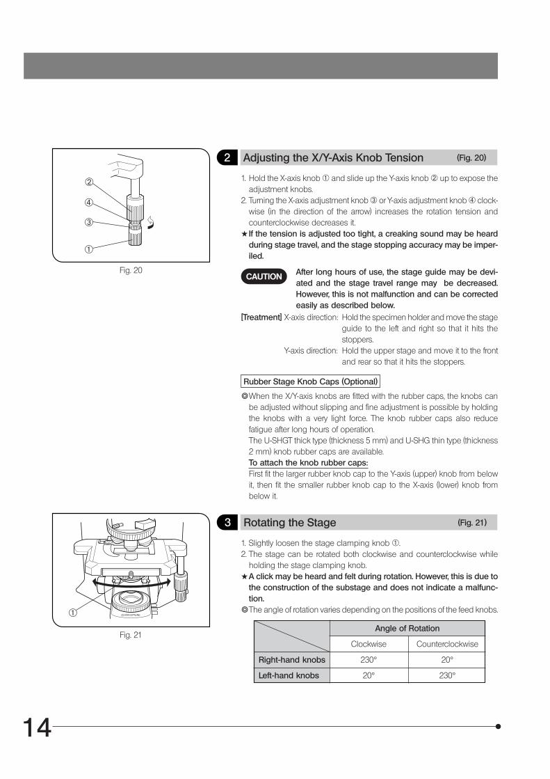
2 Adjusting the X/Y-Axis Knob Tension (Fig. 20)
1. Hold the X-axis knob @ and slide up the Y-axis knob ² up to expose theadjustment knobs.
2. Turning the X-axis adjustment knob ³ or Y-axis adjustment knob | clock-wise (in the direction of the arrow) increases the rotation tension andcounterclockwise decreases it.
#If the tension is adjusted too tight, a creaking sound may be heardduring stage travel, and the stage stopping accuracy may be imper-iled.
After long hours of use, the stage guide may be devi-ated and the stage travel range may be decreased.However, this is not malfunction and can be correctedeasily as described below.
CAUTION
[Treatment] X-axis direction: Hold the specimen holder and move the stageguide to the left and right so that it hits thestoppers.
Y-axis direction: Hold the upper stage and move it to the frontand rear so that it hits the stoppers.
Rubber Stage Knob Caps (Optional)
}When the X/Y-axis knobs are fitted with the rubber caps, the knobs canbe adjusted without slipping and fine adjustment is possible by holdingthe knobs with a very light force. The knob rubber caps also reducefatigue after long hours of operation.The U-SHGT thick type (thickness 5 mm) and U-SHG thin type (thickness2 mm) knob rubber caps are available.To attach the knob rubber caps:First fit the larger rubber knob cap to the Y-axis (upper) knob from belowit, then fit the smaller rubber knob cap to the X-axis (lower) knob frombelow it.
3 Rotating the Stage (Fig. 21)
1. Slightly loosen the stage clamping knob @.2. The stage can be rotated both clockwise and counterclockwise while
holding the stage clamping knob.#A click may be heard and felt during rotation. However, this is due to
the construction of the substage and does not indicate a malfunc-tion.
}The angle of rotation varies depending on the positions of the feed knobs.
Angle of Rotation
Clockwise Counterclockwise
Right-hand knobs 230° 20°
Left-hand knobs 20° 230°
Fig. 20
Fig. 21
@
²
³
|
@

15
BX61
4 Adjusting the Stage Height (Figs. 22 & 23)
}By lowering the position of the substage, the microscope will accommo-date specimens with maximum height of 35 mm. This is useful whenobserving metallurgical specimens and other thick objects.
1. Press the stage DOWN button @ to lower the stage to the lower limit,then remove the stage from the microscope.
2. Using an Allen screwdriver, loosen the substage bracket clamping screw² and remove the substage.
3. Press the stage UP button ³ and raise the focusing block ƒ to wherethe stopper screw | on the arm becomes visible.
4. Using the Allen screwdriver, loosen and remove the upper stopper screw|.
5. Reattach substage bracket and stage.}Retain the removed stopper screw | and take care not to lose it.
Fig. 22
Fig. 23
²
³
@
| ƒ
16
3-4 Observation Tube
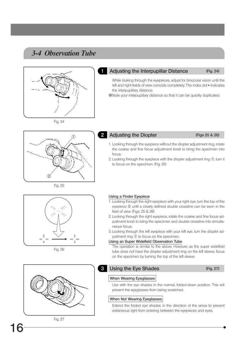
1 Adjusting the Interpupillar Distance (Fig. 24)
While looking through the eyepieces, adjust for binocular vision until theleft and right fields of view coincide completely. The index dot · indicatesthe interpupillary distance.
}Note your interpupillary distance so that it can be quickly duplicated.
2 Adjusting the Diopter (Figs 25 & 26)
1. Looking through the eyepiece without the diopter adjustment ring, rotatethe coarse and fine focus adjustment knob to bring the specimen intofocus.
2. Looking through the eyepiece with the diopter adjustment ring @, turn itto focus on the specimen. (Fig. 25)
Using a Finder Eyepiece1. Looking through the right eyepiece with your right eye, turn the top of the
eyepiece ² until a clearly defined double crossline can be seen in thefield of view. (Figs. 25 & 26)
2. Looking through the right eyepiece, rotate the coarse and fine focus ad-justment knob to bring the specimen and double crossline into simulta-neous focus.
3. Looking through the left eyepiece with your left eye, turn the diopter ad-justment ring @ to focus on the specimen.
Using an Super Widefield Observation TubeThe operation is similar to the above. However, as the super widefieldtube does not have the diopter adjustment ring on the left sleeve, focuson the specimen by turning the top of the left sleeve.
3 Using the Eye Shades (Fig. 27)
When Wearing Eyeglasses
Use with the eye shades in the normal, folded-down position. This willprevent the eyeglasses from being scratched.
When Not Wearing Eyeglasses
Extend the folded eye shades in the direction of the arrow to preventextraneous light from entering between the eyepieces and eyes.
Fig. 24
Fig. 25
Fig. 26
Fig. 27
@
²

17
BX61
4 Using the Eyepiece Micrometer Disk (Fig. 28)
When the WHN10X-H (or WHN10X) eyepieces are used, an eyepiecemicrometer disk can be inserted in one of them. When the eyepiecedoes not have a diopter adjustment mechanism, however, it is hard tofocus on the micrometer disk if the operator has poor eyesight. Shouldthat be the case, adjust the focus with eyeglasses on.Use 24 mm dia. x 1.5 mm thick micrometer disks.Following Fig. 28, turn the built-in micrometer-mounting frame ²counterclockwise to remove it from the eyepiece and place a micrometerdisk.Screw the micrometer mounting frame back into the eyepiece sleeve.Fig. 28
Fig. 29
@
²
@5 (Fig. 29)
Trinocular tubePushed in Middle position Pulled out
U-TR30-2
100% for binocu-lar eyepieces
20% for binoculareyepieces, 80% forTV/photography 100% for TV/
photography
Selecting the Light Path of theTrinocular Tube
Slide the light path selector knob @ to select the desired light path.
U-TR30NIR*
Light path selector knob position
* With the infrared trinocular tube, infrared observation up to 1000 nm ispossible. For details, consult your Olympus representative.
50% for binoculareyepieces, 50% forTV/photography
U-SWTR-3
18
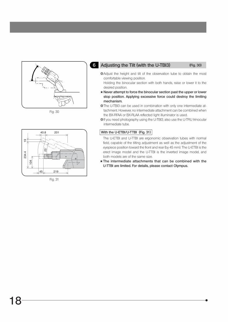
6 Adjusting the Tilt (with the U-TBI3) (Fig. 30)
}Adjust the height and tilt of the observation tube to obtain the mostcomfortable viewing position.Holding the binocular section with both hands, raise or lower it to thedesired position.
#Never attempt to force the binocular section past the upper or lowerstop position. Applying excessive force could destroy the limitingmechanism.
}The U-TBI3 can be used in combination with only one intermediate at-tachment. However, no intermediate attachment can be combined whenthe BX-RFAA or BX-RLAA reflected light illuminator is used.
}If you need photography using the U-TBI3, also use the U-TRU trinocularintermediate tube.
With the U-ETBI/U-TTBI (Fig. 31)
The U-ETBI and U-TTBI are ergonomic observation tubes with normalfield, capable of the tilting adjustment as well as the adjustment of theeyepiece position toward the front and rear (by 45 mm). The U-ETBI is theerect image model and the U-TTBI is the inverted image model, andboth models are of the same size.
#The intermediate attachments that can be combined with theU-TTBI are limited. For details, please contact Olympus.
Fig. 30
Fig. 31

19
BX61
3-5 Condenser
1 Centering the Condenser (Figs. 32 & 33)
1. Fit the Allen screwdriver @ into the condenser height adjustment screwand turn the tool counterclockwise to raise the condenser to its upperlimit.
2. Focus on the specimen using the 10X objective.#When using a swing-out condenser, move the top lens into the light
path.3. Rotate the field iris diaphragm ring ² in the direction of the arrow so that
the diaphragm image comes inside the field of view.4. Turn the Allen screwdriver @ to focus on the diaphragm image.5. Fit the Allen screwdrivers into the two condenser centering screws ³
and turn them to move the iris diaphragm image to the center of the fieldof view.
6. Gradually open the field iris diaphragm. The condenser is properly cen-tered if the iris image is centered and inscribed in the field of view.
7. During actual use, open the field diaphragm slightly until its image cir-cumscribes the field of view.
Effects of Field Iris Diaphragm (Fig. 33)
The field iris diaphragm restricts the diameter of the beam of light enter-ing the objective and thus excludes extraneous light, improving imagecontrast. The diameter of the field iris should e adjusted for objectivepower to the extent that it just circumscribes the field of view. (See “Com-patibility of Objectives and Condensers” on the next page.)
Fig. 32
Fig. 33
@
² ³

20
Aperture irisdiaphragm image
Aperture Iris Diaphragm (Figs. 34 & 35)
· The aperture iris diaphragm determines the numerical aperture of theillumination system. It has an effect of adjusting image resolution andcontrast. Stopping down the aperture iris diaphragm increases the depthof focus.
· Since the contrast of microscope specimens is ordinarily low, setting thecondenser aperture iris diaphragm to between 70 and 80% of the N.A. ²of the objective in use is usually recommended.Adjust the ratio by removing the eyepiece and looking into the eyepiecesleeve while adjusting the aperture iris diaphragm ring @ until the imageshown in Fig. 34 is seen.
}Using the numerical aperture scale:You can use the condenser numerical aperture scale by adjusting theaperture iris diaphragm ring @. (Fig. 35)
2 Compatibility of Objectives and Condensers
Fig. 34
Fig. 35
N.A. scale
ObjectiveMagnification
Condenser
Achromat/aplanatU-AAC
Swing-outU-SC3
Motorized universalU-UCD8A
1.25X Applicable to FN 22Applicable when U-FWCO1.25Xis combined.
2X Applicable (FN 26.5) by movingtop lens out of the light path.*
Applicable (FN 26.5) by movingtop lens out of the light path.4X
10-60X Applicable(FN 26.5)
Engage top lens in light path.(FN 26.5)
Engage top lens in light path.(FN 26.5)100X
* When using the U-SC3 swing-out condenser together with a 1.25X to 4X objective, fully open the condenser aperture irisdiaphragm and use the field iris diaphragm in the base as aperture diaphragm. With the 1.25X to 2X objectives, thesurroundings of the field of view may become dark.
}To obtain better illumination in photomicrography using a 1.25X to 4X objective, use of the U-ULC-2 for ultralow magnifi-cation is recommended.
Objective pupil
70-80%
30-20%
@
²
21
BX61
3-6 Immersion Objectives
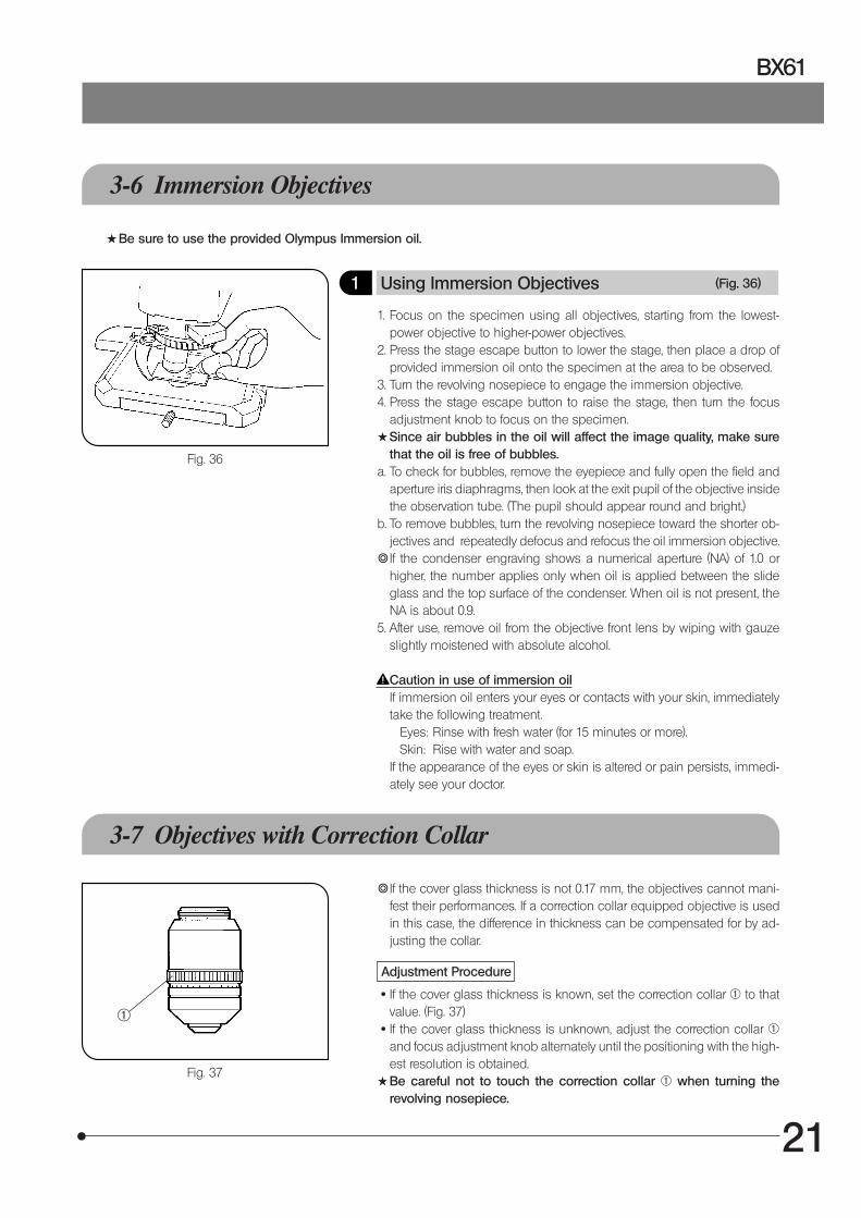
1 Using Immersion Objectives (Fig. 36)
1. Focus on the specimen using all objectives, starting from the lowest-power objective to higher-power objectives.
2. Press the stage escape button to lower the stage, then place a drop ofprovided immersion oil onto the specimen at the area to be observed.
3. Turn the revolving nosepiece to engage the immersion objective.4. Press the stage escape button to raise the stage, then turn the focus
adjustment knob to focus on the specimen.#Since air bubbles in the oil will affect the image quality, make sure
that the oil is free of bubbles.a. To check for bubbles, remove the eyepiece and fully open the field and
aperture iris diaphragms, then look at the exit pupil of the objective insidethe observation tube. (The pupil should appear round and bright.)
b. To remove bubbles, turn the revolving nosepiece toward the shorter ob-jectives and repeatedly defocus and refocus the oil immersion objective.
}If the condenser engraving shows a numerical aperture (NA) of 1.0 orhigher, the number applies only when oil is applied between the slideglass and the top surface of the condenser. When oil is not present, theNA is about 0.9.
5. After use, remove oil from the objective front lens by wiping with gauzeslightly moistened with absolute alcohol.
Caution in use of immersion oilIf immersion oil enters your eyes or contacts with your skin, immediatelytake the following treatment.
Eyes: Rinse with fresh water (for 15 minutes or more).Skin: Rise with water and soap.
If the appearance of the eyes or skin is altered or pain persists, immedi-ately see your doctor.
3-7 Objectives with Correction Collar
}If the cover glass thickness is not 0.17 mm, the objectives cannot mani-fest their performances. If a correction collar equipped objective is usedin this case, the difference in thickness can be compensated for by ad-justing the collar.
Adjustment Procedure
· If the cover glass thickness is known, set the correction collar @ to thatvalue. (Fig. 37)
· If the cover glass thickness is unknown, adjust the correction collar @and focus adjustment knob alternately until the positioning with the high-est resolution is obtained.
#Be careful not to touch the correction collar @ when turning therevolving nosepiece.
Fig. 36
Fig. 37
@
#Be sure to use the provided Olympus Immersion oil.
22
TROUBLESHOOTING GUIDE
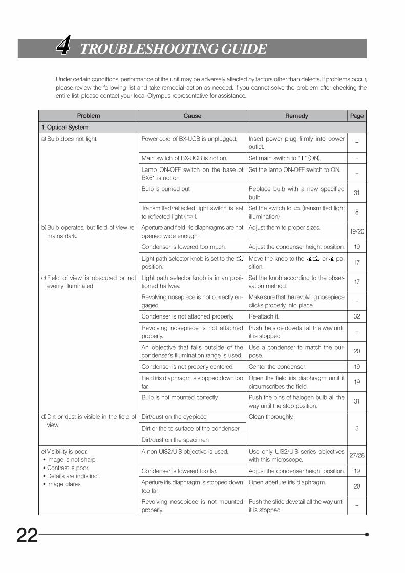
Under certain conditions, performance of the unit may be adversely affected by factors other than defects. If problems occur,please review the following list and take remedial action as needed. If you cannot solve the problem after checking theentire list, please contact your local Olympus representative for assistance.
Problem Cause Remedy Page
1. Optical System
a) Bulb does not light. Power cord of BX-UCB is unplugged. Insert power plug firmly into poweroutlet.
–
Main switch of BX-UCB is not on. Set main switch to “ I ” (ON). –
Lamp ON-OFF switch on the base ofBX61 is not on.
Set the lamp ON-OFF switch to ON.–
Bulb is burned out. Replace bulb with a new specifiedbulb.
31
Transmitted/reflected light switch is setto reflected light ( ).
Set the switch to (transmitted lightillumination).
8
b) Bulb operates, but field of view re-mains dark.
Aperture and field iris diaphragms are notopened wide enough.
Adjust them to proper sizes.19/20
Condenser is lowered too much. Adjust the condenser height position. 19
Light path selector knob is set to the position.
Move the knob to the or po-sition.
17
c) Field of view is obscured or notevenly illuminated
Light path selector knob is in an posi-tioned halfway.
Set the knob according to the obser-vation method.
17
Revolving nosepiece is not correctly en-gaged.
Make sure that the revolving nosepiececlicks properly into place.
–
Condenser is not attached properly. Re-attach it. 32
Revolving nosepiece is not attachedproperly.
Push the side dovetail all the way untilit is stopped.
–
An objective that falls outside of thecondenser’s illumination range is used.
Use a condenser to match the pur-pose.
20
Condenser is not properly centered. Center the condenser. 19
Field iris diaphragm is stopped down toofar.
Open the field iris diaphragm until itcircumscribes the field.
19
Bulb is not mounted correctly. Push the pins of halogen bulb all theway until the stop position.
31
d) Dirt or dust is visible in the field ofview.
Dirt/dust on the eyepiece Clean thoroughly.
3Dirt or the to surface of the condenser
Dirt/dust on the specimen
e) Visibility is poor. · Image is not sharp. · Contrast is poor. · Details are indistinct. · Image glares.
A non-UIS2/UIS objective is used. Use only UIS2/UIS series objectiveswith this microscope.
27/28
Condenser is lowered too far. Adjust the condenser height position. 19
Aperture iris diaphragm is stopped downtoo far.
Open aperture iris diaphragm.20
Revolving nosepiece is not mountedproperly.
Push the slide dovetail all the way untilit is stopped.
–
23
BX61
Problem Cause Remedy Page
Correction collar on correction collarequipped objective is not properly ad-justed.
e) Visibility is poor. · Image is not sharp. · Contrast is poor. · Details are indistinct. · Image glares.
While focusing, turn the correction col-lar to find the best position. 21
Front lens of objective is dirty. Clean objective. 3
Immersion oil is not being used with anoil immersion objective.
Use immersion oil.21
Immersion oil contains bubbles. Remove the bubbles. 21
Recommended immersion oil is notused.
Use the provided immersion oil.21
Dirt/dust on specimen. Clean it.3
Dirt/dust on condenser
Inappropriate object side or cover glassthickness.
Replace with glass of recommendedthickness.
13
f ) One side of image is blurred. Revolving nosepiece is not correctlymounted.
Push slide dovetail all the way until itis stopped.
–
Stage is not correctly mounted. Re-attach it. 15
Objective is not correctly engaged in lightpath.
Make sure that revolving nosepiececlicks into place correctly.
–
Specimen is not correctly mounted onstage.
Place specimen correctly on to ofstage and secure it with slide holder.
13
g) Image appears to waver. Revolving nosepiece is not correctedmounted.
Push slide dovetail all the way until itis stopped.
–
Objective is not correctly engaged inlight path.
Make sure that revolving nosepiececlicks into place correctly.
–
Condenser is not properly centered. Center the condenser. 19
h) Field of view becomes only slightlybrighter when the voltage is raised.
Condenser is not properly centered. Center the condenser. 19
Condenser is lowered too far. Adjust the condenser height position. 19
2. Electrical System
a) Bulb intermittently lights and goesout.
Bulb is nearly burned out. Replace bulb. 31
A connector is not properly connected. Check all connectors. –
b) Bulb burns out almost immediately. Wrong type of bulb is being used. Use correct bulb type. 31
c) All voltage indicator LEDs light andvoltage cannot be varied by press-ing light intensity adjustment but-ton.
Bulb is not installed. Install bulb. 31
Bulb is burned out. Replace bulb. 31
Lamp housing is not connected. Connect lamp housing correctly. –
d) Brightness does not change whenyou press light intensity adjustmentbutton.
Bulb is burned out. Replace bulb.31
3. Focusing Block
a) Image cannot be focused. When adjusting stage height, you forgotto reattach upper stopper screw.
Re-attach upper stopper screw.15
b) Stage rises too high and destroysspecimen.
Substage is not installed properly. Re-attach substage.11

24
Problem Cause Remedy Page
c) Coarse adjustment will not go allthe way down.
Condenser holder is too low. Raise condenser holder.32
d) Objective makes contact with speci-men before focus is obtained.
Specimen is mounted upside down. Mount specimen correctly. –
4. Observation Tube
a) Field of view of one eye does notmatch that of the other.
Interpupillary distance is incorrect. Adjust interpupillary distance. 16
Incorrect diopter adjustment. Adjust diopter. 16
Different eyepieces are used on left andright.
Change on eyepiece to match theother so that both sides are the sametype.
–
Your view is not accustomed to micro-scope observation.
Upon looking into eyepieces, try look-ing at overall field before concentrat-ing on specimen range. You may alsofind it helpful to look up and into dis-tance for a moment before lookingback into microscope.
–
5. Stage
a) Image shifts when you touch stage. Stage is not properly mounted. Clamp stage. –
b) Specimen stops midway on the X-axis traverse.
Specimen is not correctly positioned. Place specimen correctly.13
c) X-axis and/or Y-axis knobs are tootight or too loose.
X-axis and/or Y-axis adjustment knobsare set at a position where tension is toohigh or too low.
Adjust tension.14
d) Stroke is decreased. Stage guide is deviated. Correct deviation as instructed onpage 14.
14
25
BX61
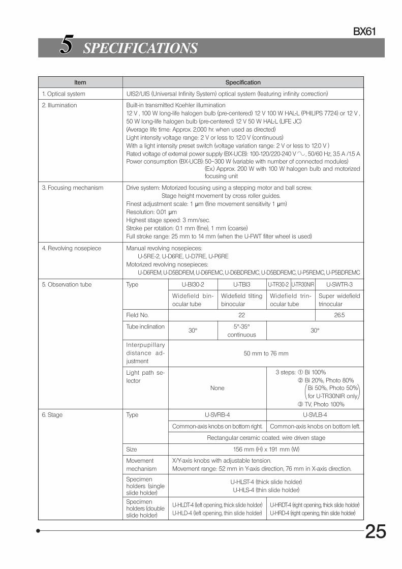
SPECIFICATIONS
Item Specification
1. Optical system UIS2/UIS (Universal Infinity System) optical system (featuring infinity correction)
2. Illumination Built-in transmitted Koehler illumination12 V , 100 W long-life halogen bulb (pre-centered) 12 V 100 W HAL-L (PHILIPS 7724) or 12 V ,50 W long-life halogen bulb (pre-centered) 12 V 50 W HAL-L (LIFE JC)(Average life time: Approx. 2,000 hr. when used as directed)Light intensity voltage range: 2 V or less to 12.0 V (continuous)With a light intensity preset switch (voltage variation range: 2 V or less to 12.0 V )Rated voltage of external power supply (BX-UCB): 100-120/220-240 V , 50/60 Hz, 3.5 A /1.5 APower consumption (BX-UCB): 50–300 W (variable with number of connected modules)
(Ex.) Approx. 200 W with 100 W halogen bulb and motorizedfocusing unit
3. Focusing mechanism Drive system: Motorized focusing using a stepping motor and ball screw.Stage height movement by cross roller guides.
Finest adjustment scale: 1 μm (fine movement sensitivity 1 μm)Resolution: 0.01 μmHighest stage speed: 3 mm/sec.Stroke per rotation: 0.1 mm (fine), 1 mm (coarse)Full stroke range: 25 mm to 14 mm (when the U-FWT filter wheel is used)
4. Revolving nosepiece Manual revolving nosepieces:U-5RE-2, U-D6RE, U-D7RE, U-P6RE
Motorized revolving nosepieces:U-D6REM, U-D5BDREM, U-D6REMC, U-D6BDREMC, U-D5BDREMC, U-P5REMC, U-P5BDREMC
5. Observation tube Type U-BI30-2 U-TBI3 U-TR30-2 U-SWTR-3
Widefield bin-ocular tube
Widefield tiltingbinocular
Widefield trin-ocular tube
Super widefieldtrinocular
Field No. 22 26.5
Tube inclination30°
5°-35°continuous
30°
Interpupil larydistance ad-justment
50 mm to 76 mm
Light path se-lector
None
3 steps: @ Bi 100%² Bi 20%, Photo 80% Bi 50%, Photo 50% for U-TR30NIR only³ TV, Photo 100%
6. Stage Type U-SVRB-4 U-SVLB-4
Common-axis knobs on bottom right. Common-axis knobs on bottom left.
Rectangular ceramic coated. wire driven stage
Size 156 mm (H) x 191 mm (W)
Movementmechanism
X/Y-axis knobs with adjustable tension.Movement range: 52 mm in Y-axis direction, 76 mm in X-axis direction.
Specimenholders (singleslide holder)
U-HLST-4 (thick slide holder)U-HLS-4 (thin slide holder)
Specimenholders (doubleslide holder)
U-HLDT-4 (left opening, thick slide holder)U-HLD-4 (left opening, thin slide holder)
U-HRDT-4 (right opening, thick slide holder)U-HRD-4 (right opening, thin slide holder)
U-TR30NIR
26
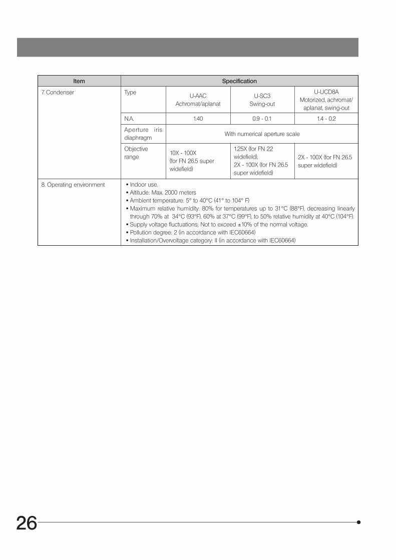
Item Specification
7. Condenser TypeU-AAC
Achromat/aplanatU-SC3
Swing-out
U-UCD8AMotorized, achromat/
aplanat, swing-out
N.A. 1.40 0.9 - 0.1 1.4 - 0.2
Aperture irisdiaphragm
With numerical aperture scale
Objectiverange
10X - 100X(for FN 26.5 superwidefield)
1.25X (for FN 22widefield),2X - 100X (for FN 26.5super widefield)
2X - 100X (for FN 26.5super widefield)
8. Operating environment · Indoor use. · Altitude: Max. 2000 meters · Ambient temperature: 5° to 40°C (41° to 104° F) · Maximum relative humidity: 80% for temperatures up to 31°C (88°F), decreasing linearly
through 70% at 34°C (93°F), 60% at 37°C (99°F), to 50% relative humidity at 40°C (104°F). · Supply voltage fluctuations; Not to exceed ±10% of the normal voltage. · Pollution degree: 2 (in accordance with IEC60664) · Installation/Overvoltage category: II (in accordance with IEC60664)

27
BX61
4X 0.16 13.0 — 2.10 40X 99.6 5.510X2 0.4 3.1 0.17 0.84 100X 15.9 2.220X 0.75 0.6 0.17 0.45 200X 4.29 1.1
20XO 0.85 0.17 — 0.39 200X 3.5 1.1 Oil immersion40X2 0.95 0.18 0.17 0.35 400X 1.9 0.55 Correction collar
60XW 1.2 0.28 0.17 0.28 600X 1.03 0.37 Water immersion 60XO 1.35 0.15 0.17 0.25 600X 0.89 0.37 Oil immersion 100XO 1.4 0.13 0.17 0.24 1000X 0.59 0.22 Oil immersion
4X 0.1 18.5 — 3.40 40X 180.0 5.5
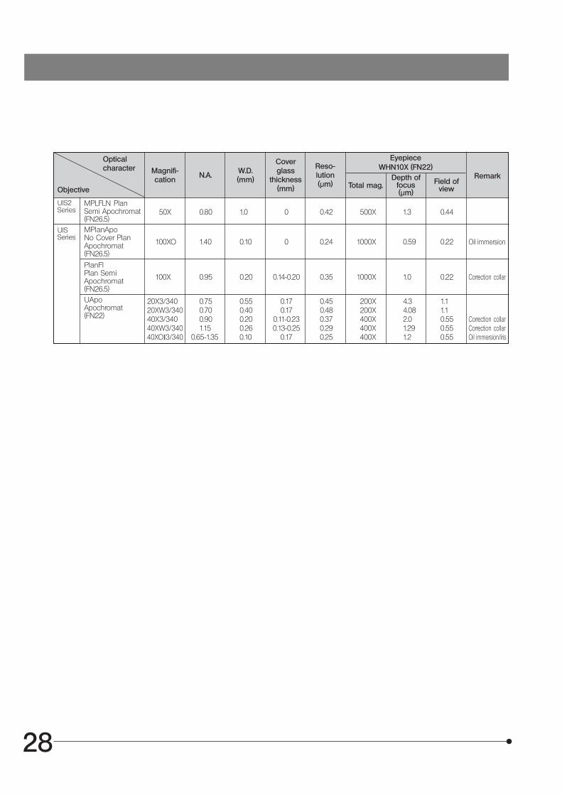
OPTICAL CHARACTERISTICS «UIS2 (UIS) Series»
The following table shows the optical characteristics of com-binations of eyepieces and objectives. The figure on the rightshows the performance data engraved on the objectives.
NOTE
Refer to the latest catalogue or consult your local Olympusrepresentative for the updated information on the eyepiecesand objectives that can be combined with this microscope.
Objective type
Number of apertureMagnification
Cover glass thickness
Mechanical tubelength
Color band
Oil: Oil immersionIris: Iris diaphragm
Field number (FN)
UIS series objectives not listed here can also be combined with this microscope.
Opticalcharacter Magnifi-
cationN.A.
W.D.(mm)
Coverglass
thickness(mm)
Reso-lution(μm)
EyepieceWHN10X (FN22)
Remark
Objective Total mag.Depth of
focus(μm)
Field ofview
PlanN-P PlanAchromat forpolarized light(FN22)
10X 0.25 6.0 — 1.30 100X 28.0 2.220X 0.4 3.0 0.17 0.84 200X 9.3 1.140X 0.65 0.45 0.17 0.52 400X 2.0 0.55
100XO 1.25 0.13 — 0.27 1000X 0.69 0.22
AchN-P Achromatfor polarized light(FN22)
2X 0.06 5.8 — 5.59 20X 560.1 11.04X 0.1 18.5 — 3.36 40X 175.0 5.5
10X 0.25 10.6 — 1.34 100X 28.0 2.220X 0.4 1.2 0.17 0.84 200X 9.27 1.140X 0.65 0.6 0.17 0.52 400X 3.04 0.55
50XOI 0.5-0.9 0.2 0.17 0.37 500X 1.7 0.44 Oil immersion/Iris 100XO 1.25 0.15 — 0.27 1000X 0.69 0.22 Oil immersion
PlanN PlanAchromat (FN22)
4X 0.13 17.0 — 2.58 40X 127.2 5.510X2 0.3 10.0 — 1.12 100X 22.4 2.220X 0.5 2.1 0.17 0.67 200X 7.0 1.140X 0.75 0.51 0.17 0.45 400X 2.52 0.55
40XO 1.3 0.2 0.17 0.26 400X 1.27 0.55 Oil immersion60X 0.9 0.2 0.17 0.37 600X 1.5 0.37 Correction collar
60XOI 0.65-1.25 0.12 0.17 0.27 600X 0.98 0.37 Oil immersion/Iris 100XO2 1.30 0.2 0.17 0.26 1000X 0.66 0.22 Oil immersion 100XOI2 0.6-1.30 0.2 0.17 0.26 1000X 0.66 0.22 Oil immersion/Iris
UPlanFLN PlanSemiApochromat(FN26.5)
UPlanSApo PlanApochromat(FN26.5)
1.25X 0.04 5.0 — 8.39 12.5X 1326.8 17.62X 0.08 6.2 — 4.19 20X 398.3 11.0
60XO 1.42 0.15 0.17 0.24 600X 0.83 0.37 Oil immersion
PlanApoN PlanApochromat(FN26.5)
UIS2Series
28
50X 0.80 1.0 0 0.42 500X 1.3 0.44
Opticalcharacter Magnifi-
cationN.A. W.D.
(mm)
Coverglass
thickness(mm)
Reso-lution(µm)
EyepieceWHN10X (FN22)
Remark
Objective Total mag.Depth of
focus(µm)
Field ofview
MPLFLN PlanSemi Apochromat(FN26.5)
UIS2Series
100XO 1.40 0.10 0 0.24 1000X 0.59 0.22 Oil immersion
MPlanApoNo Cover PlanApochromat(FN26.5)
100X 0.95 0.20 0.14-0.20 0.35 1000X 1.0 0.22 Correction collar
PlanFlPlan SemiApochromat(FN26.5)
20X3/340 0.75 0.55 0.17 0.45 200X 4.3 1.120XW3/340 0.70 0.40 0.17 0.48 200X 4.08 1.140X3/340 0.90 0.20 0.11-0.23 0.37 400X 2.0 0.55 Correction collar40XW3/340 1.15 0.26 0.13-0.25 0.29 400X 1.29 0.55 Correction collar40XOI3/340 0.65-1.35 0.10 0.17 0.25 400X 1.2 0.55 Oil immersion/Iris
UApoApochromat(FN22)
UISSeries

29
BX61
ASSEMBLY
7-1 Assembly Diagram
The diagram below shows the sequence of assembly of the various modules. The numbers indicate the order of assembly.The BX61TRF microscope frame is assembled in the same procedures.The module model numbers shown in the following diagram are merely the typical examples. For the modules with whichthe model numbers are not given, please consult your Olympus representative or the catalogues.
#When assembling the microscope, make sure that all parts are free of dust and dirt, and avoid scratching any partsor touching glass surfaces.Assembly steps enclosed in will be detailed on the subsequent pages.
}Most assembly operations are possible by using the Allen screwdriver ( ) provided with the microscope. How-ever, the assembly of the reflected light illuminator requires the use of the provided Allen wrench ( ) for clamping theinternal screws (to ensure the performance, we recommend that you have your Olympus representative assemble orremove this module).
EyepieceWHN10X (FN 22)35WHN10X (FN 22)SWH10X-H (FN 26.5)35SWH10X (FN 26.5)
}For the electrical connections, refer to the instruction manual of the BX-UCB control box.For the setup and installation of the Z-board, see page 30.
Observation tubeU-BI30-2 (FN 22)U-TR30-2 (FN 22)U-TR30NIR (FN 22)U-TBI3 (FN 22)U-SWTR-3 (FN 26.5)U-ETBI (FN 22)U-TTBI (FN 22)
IntermediateattachmentU-EPA2U-DO3U-TRU, etc.
Tube clampingscrew
Revolving nosepieceU-D6REU-D6REMU-D6REMC, etc.
Specimenholderclampingknobs
Stage clampingknob
UIS2/UISseriesobjective
StageU-SVRB-4U-SVLB-4U-SRG
CondenserU-SC3U-AACU-UCD8A
Reflected light illuminatorBX-RFAABX-RLAA Reflected
lamphousing
Microscope frame(Transmitted/reflectedlight specification)BX61TRF
100 W halogen bulb12V100WHAL-L12V50WHAL-L
100 W halogenlamp housingU-LH100-3
Revolvingnosepiececlamping screw
Lamp socketclamping screw
Microscope frame(Transmitted lightspecification)BX61TRFCondenser clamping
screw
Slide holderU-HLDT-4U-HRDT-4U-HLST-4

30
Fig. 38
Fig. 39
7-2 Detailed Assembly Procedures
Setup and Installation of the Z-Board
}The on-board DIP switches on the Z-board have been set up for theBX61 or BX62 (all of switches S1, S2 and S3 are set to OFF).
Changing the Settings of On-Board DIP Switches (Fig. 38)
#Leave all other DIP switches than those mentioned below in the OFFpositions.
}Switch only the DIP switches mentioned below to the ON positions.
S2 No. 4
· This replaces the functions of the F/C switching and stage escape but-tons on the left side of the BX61/BX62 with the stage DOWN and UPbuttons.
S3 No. 1
· This turns off the automatic initialization and sets the remote mode whichis the default.
S3 No. 4
· When the U-FWT filter wheel is not used, this changes the focus adjust-ment stroke from 15 mm to 25 mm.
Mounting the Z-Board (Fig. 39)
}Be sure to set the main switch on the BX-UCB control box @ to “ ”(OFF) before proceeding to mounting the Z-board.
1. Loosen the 6 clamping knobs on the 2 option slot covers on the rear ofthe BX-UCB and remove the covers and knobs.
2. Insert the Z-board ² into the BX-UCB by aligning the orientation of theconnector inside the BX-UCB and that of the Z-board. Push in the boardalong the board rails all the way so that the connector is plugged insecurely.
3. Clamp the Z-board ² using two of the clamping knobs removed above.Also attach one of the removed covers ³ using the other four clampingknobs removed above.
}Store the other, removed cover in a safe place.
@²
³
S1 S2 S3
#For use in focusing control, only either the Z-board or AF control board can be installed on the BX-UCB.Installing different boards on it may result in malfunction. When using the AF control board instead of the Z-board,set the on-board DIP switches on the AF control board to the same settings as the following settings that areoriginally intended for the Z-board.
31
BX61
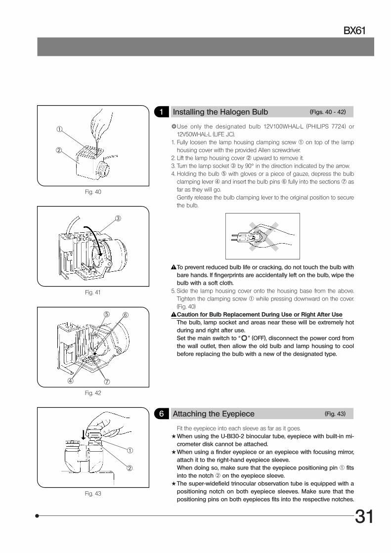
1 Installing the Halogen Bulb (Figs. 40 - 42)
}Use only the designated bulb 12V100WHAL-L (PHILIPS 7724) or12V50WHAL-L (LIFE JC).
1. Fully loosen the lamp housing clamping screw @ on top of the lamphousing cover with the provided Allen screwdriver.
2. Lift the lamp housing cover ² upward to remove it.3. Turn the lamp socket ³ by 90° in the direction indicated by the arrow.4. Holding the bulb ƒ with gloves or a piece of gauze, depress the bulb
clamping lever | and insert the bulb pins … fully into the sections † asfar as they will go.Gently release the bulb clamping lever to the original position to securethe bulb.
To prevent reduced bulb life or cracking, do not touch the bulb withbare hands. If fingerprints are accidentally left on the bulb, wipe thebulb with a soft cloth.
5. Side the lamp housing cover onto the housing base from the above.Tighten the clamping screw @ while pressing downward on the cover.(Fig. 40)Caution for Bulb Replacement During Use or Right After UseThe bulb, lamp socket and areas near these will be extremely hotduring and right after use.Set the main switch to “ ” (OFF), disconnect the power cord fromthe wall outlet, then allow the old bulb and lamp housing to coolbefore replacing the bulb with a new of the designated type.
6 Attaching the Eyepiece (Fig. 43)
Fit the eyepiece into each sleeve as far as it goes.#When using the U-BI30-2 binocular tube, eyepiece with built-in mi-
crometer disk cannot be attached.#When using a finder eyepiece or an eyepiece with focusing mirror,
attach it to the right-hand eyepiece sleeve.When doing so, make sure that the eyepiece positioning pin @ fitsinto the notch ² on the eyepiece sleeve.
#The super-widefield trinocular observation tube is equipped with apositioning notch on both eyepiece sleeves. Make sure that thepositioning pins on both eyepieces fits into the respective notches.
Fig. 40
Fig. 41
Fig. 42
Fig. 43
@
²
³
|
ƒ …
†
@
²
32
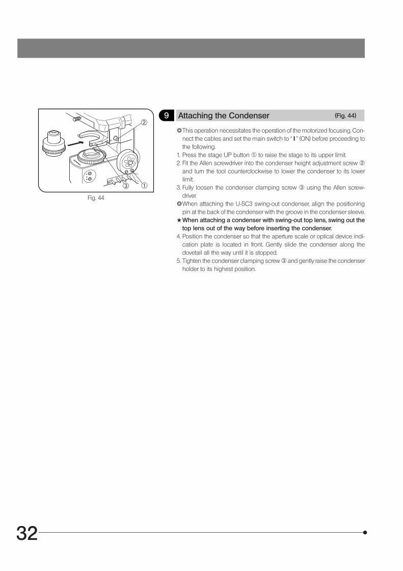
9 Attaching the Condenser (Fig. 44)
}This operation necessitates the operation of the motorized focusing. Con-nect the cables and set the main switch to “ I ” (ON) before proceeding tothe following.
1. Press the stage UP button @ to raise the stage to its upper limit.2. Fit the Allen screwdriver into the condenser height adjustment screw ²
and turn the tool counterclockwise to lower the condenser to its lowerlimit.
3. Fully loosen the condenser clamping screw ³ using the Allen screw-driver.
}When attaching the U-SC3 swing-out condenser, align the positioningpin at the back of the condenser with the groove in the condenser sleeve.
#When attaching a condenser with swing-out top lens, swing out thetop lens out of the way before inserting the condenser.
4. Position the condenser so that the aperture scale or optical device indi-cation plate is located in front. Gently slide the condenser along thedovetail all the way until it is stopped.
5. Tighten the condenser clamping screw ³ and gently raise the condenserholder to its highest position.
Fig. 44
@
²
³

33
BX61
PROPER SELECTION OF THE POWER SUPPLY CORD
If no power supply cord is provided, please select the proper power supply cord for the equipment by referring to “ Specifications ” and“ Certified Cord ” below:CAUTION: In case you use a non-approved power supply cord for Olympus products, Olympus can no longer warrant the
electrical safety of the equipment.
Specifications
Voltage RatingCurrent RatingTemperature RatingLengthFittings Configuration
125V AC (for 100-120V AC area) or, 250V AC (for 220-240V AC area)6A minimum60°C minimum3.05 m maximumGrounding type attachment plug cap. Opposite terminates in molded-on IEC con-figuration appliance coupling.
Table 1 Certified Cord
A power supply cord should be certified by one of the agencies listed in Table 1 , or comprised of cordage marked with anagency marking per Table 1 or marked per Table 2. The fittings are to be marked with at least one of agencies listed inTable 1. In case you are unable to buy locally in your country the power supply cord which is approved by one of theagencies mentioned in Table 1, please use replacements approved by any other equivalent and authorized agencies inyour country.
Country Agency CertificationMark Country Agency
CertificationMark
Argentina
Australia
Austria
Belgium
Canada
Denmark
Finland
France
Germany
Ireland
IRAM
SAA
ÖVE
CEBEC
CSA
DEMKO
FEI
UTE
VDE
NSAI
Italy
Japan
Netherlands
Norway
Spain
Sweden
Switzerland
United Kingdom
U.S.A.
IMQ
KEMA
NEMKO
AEE
SEMKO
SEV
ASTABSI
UL
JET, JQA , TÜV,UL-APEX / MITI

34
Table 2 HAR Flexible Cord
APPROVAL ORGANIZATIONS AND CORDAGE HARMONIZATION MARKING METHODS
Approval Organization
Printed or Embossed Harmoniza-tion Marking (May be located onjacket or insulation of internal wir-ing)
Alternative Marking UtilizingBlack-Red-Yellow Thread (Lengthof color section in mm)
Black Red Yellow
Comite Electrotechnique Belge(CEBEC)
Verband Deutscher Elektrotechniker(VDE) e.V. Prüfstelle
Union Technique de l´Electricite´(UTE)
Instituto Italiano del Marchio diQualita´ (IMQ)
British Approvals Service for ElectricCables (BASEC)
N.V. KEMA
SEMKO AB Svenska ElektriskaMaterielkontrollanstalter
Österreichischer Verband fürElektrotechnik (ÖVE)
Danmarks Elektriske Materialkontroll(DEMKO)
National Standards Authority of Ireland(NSAI)
Norges Elektriske Materiellkontroll(NEMKO)
Asociacion Electrotecnica YElectronica Espanola (AEE)
Hellenic Organization forStandardization (ELOT)
Instituto Portages da Qualidade(IPQ)
Schweizerischer ElektroTechnischer Verein (SEV)
Elektriska Inspektoratet
CEBEC <HAR>
<VDE> <HAR>
USE <HAR>
IEMMEQU <HAR>
BASEC <HAR>
KEMA-KEUR <HAR>
SEMKO <HAR>
<ÖVE> <HAR>
<DEMKO> <HAR>
<NSAI> <HAR>
NEMKO <HAR>
<UNED> <HAR>
ELOT <HAR>
np <HAR>
SEV <HAR>
SETI <HAR>
10 30 10
30 10 10
30 10 30
10 30 50
10 10 30
10 30 30
10 10 50
30 10 50
30 10 30
30 30 50
10 10 70
30 10 70
30 30 70
10 10 90
10 30 90
10 30 90
Underwriters Laboratories Inc. (UL) SV, SVT, SJ or SJT, 3 X 18AWGCanadian Standards Association (CSA) SV, SVT, SJ or SJT, 3 X 18AWG


Shinjuku Monolith, 3-1, Nishi Shinjuku 2-chome, Shinjuku-ku, Tokyo, Japan
Postfach 10 49 08, 20034, Hamburg, Germany
3500 Corporate Parkway, P.O. Box 610, Center Valley, PA 18034-0610, U.S.A.
One Corporate Drive, Orangeburg, NY 10962, U.S.A.
491B River Valley Road, #12-01/04 Valley Point Office Tower, Singapore 248373
31 Gilby Road, Mount Waverley, VIC., 3149, Australia
5301 Blue Lagoon Drive, Suite 290 Miami, FL 33126, U.S.A.
Printed in Japan on May 07, 2008 M 010–²
Recommended


![INDEX [] duty trucks.pdf · ax76 4p5436 ax76 8m0760 ax77 7e6192 ax77 9y1956 bx61 6n6653 bx61 6n6655 bx61 6n6657 bx61 8n0539 bx68 4n8221 alternator bx75 6n7053 waterpump bx77 6215-61](https://img.dokumen.tips/doc/110x75/5b01ce967f8b9ab9598cdf8b/index-duty-truckspdfax76-4p5436-ax76-8m0760-ax77-7e6192-ax77-9y1956-bx61-6n6653.jpg)