Embed Size (px)
Citation preview
This instruction manual is for the Olympus DP70 Microscope Digital Camera. To ensure the safety,obtain optimum performance and familiarize yourself fully with the use of this camera, we recommendthat you study this manual thoroughly before operating the camera.For image operations including recording, editing and saving, please refer to the Online Help forthe DP70-BSW software.Retain this instruction manual in an easily accessible place near the work desk for future reference.
INSTRUCTIONS
DP70MICROSCOPE DIGITAL CAMERA
A X 6 4 7 3

NOTE: This equipment has been tested and found to comply with the limits for a Class A digital device,
pursuant to Part 15 of the FCC Rules. These limits are designed to provide reasonable protection
against harmful interference when the equipment is operated in a commercial environment. This
equipment generates, uses, and can radiate radio frequency energy and, if not installed and used in
accordance with the instruction manual, may cause harmful interference to radio communications.
Operation of this equipment in a residential area is likely to cause harmful interference in which case
the user will be required to correct the interference at his own expense.
FCC WARNING: Changes or modifications not expressly approved by the party responsible for compliance
could void the user’s authority to operate the equipment.
...................................................................................................................................................
.........................................................................................................................................................................
................................................................................................................................................................
.............................................................................................................................................................
.................................................................................................................................................................
1 Installing the PCI Interface Board 7
2 Installing the Camera Head 8-9
..................................................................................................................................
....................................................................................................................................................
1-4
5
6
7-9
17
19
20-21
22
DP70
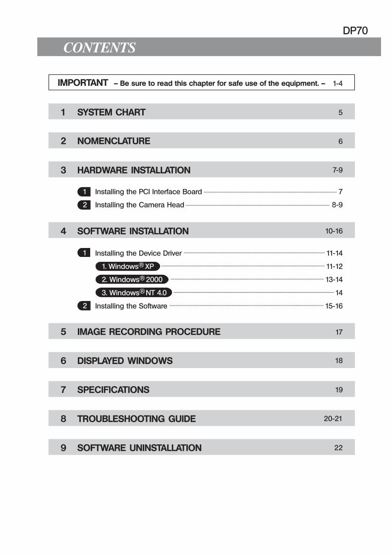
CONTENTS
IMPORTANT — Be sure to read this chapter for safe use of the equipment. —
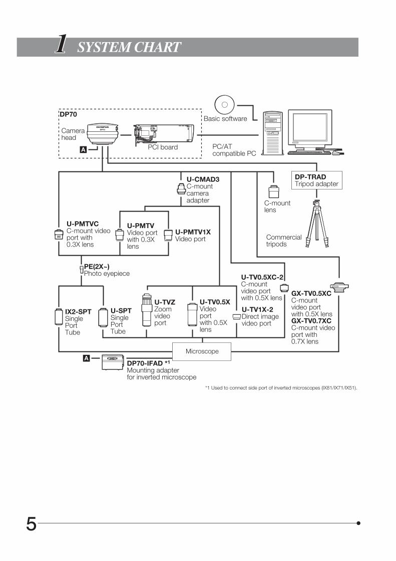
1 SYSTEM CHART
2 NOMENCLATURE
3 HARDWARE INSTALLATION
4 SOFTWARE INSTALLATION 10-16
5 IMAGE RECORDING PROCEDURE
6 DISPLAYED WINDOWS
7 SPECIFICATIONS
8 TROUBLESHOOTING GUIDE
9 SOFTWARE UNINSTALLATION
18
1 Installing the Device Driver 11-14
1. Windows R XP 11-12
2. Windows R 2000 13-14
3. Windows R NT 4.0 14
2 Installing the Software 15-16
1
1. Before connecting or disconnecting the interface cable, make sure that the main switch of the computer is set to “ ”(OFF).When connecting the interface cable, tighten firmly the lock screws on it and ensure that the connector will not slip outbefore setting the main switch to “ ” (ON).
2. The cords and cables are vulnerable to bend or twist. Do not apply excessive force to them.3. To prevent the microscope from toppling down, avoid using microscope attachments that may make the total height of
the microscope above 1 meter when they are attached.4. When installing the PCI interface board, be sure to hold it by the edge. Never touch the board surface directly, as this will
lead to malfunction.
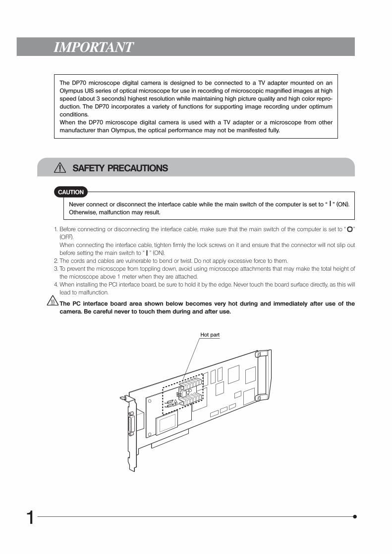
The PC interface board area shown below becomes very hot during and immediately after use of thecamera. Be careful never to touch them during and after use.
The DP70 microscope digital camera is designed to be connected to a TV adapter mounted on anOlympus UIS series of optical microscope for use in recording of microscopic magnified images at highspeed (about 3 seconds) highest resolution while maintaining high picture quality and high color repro-duction. The DP70 incorporates a variety of functions for supporting image recording under optimumconditions.When the DP70 microscope digital camera is used with a TV adapter or a microscope from othermanufacturer than Olympus, the optical performance may not be manifested fully.
IMPORTANT
SAFETY PRECAUTIONS
Never connect or disconnect the interface cable while the main switch of the computer is set to “ ” (ON).Otherwise, malfunction may result.
CAUTION
Hot part
DP70
2
Operating Environment
Restrictions
1. The recommended C-mount camera adapter is the combination U-TV1X-2 + U-CMAD3 or the U-TV0.5XC-2.(The U-TV0.5XC should not be used because it deteriorates the image flatness.)
2. Combination with the following adapters is not permitted.· U-TV0.25XC· U-TV0.35XC· U-TV0.5XC· SZX + BS + PHA + U-TV0.5XC-2 or U-TV1X-2 + U-CMAD3
3. When the U-TV0.5XC-2 is used together with a low-power objective (1.25X or 2X), the peripheral part of image may beobscured unless the U-ULC ultralow-magnification condenser is used.
4. When the DP70 is connected to the rear port of the U-DPT or U-MPH, the peripheral part of the recorded image may bedeteriorated due to the optical performance of the U-DPT or U-MPH.
5. When the U-PMTVC + PE2X are used, the peripheral part of the field of view may be obscured.6. When the U-CFU is used, it is required to set the exposure to a loner period than 1/30 sec. using the manual exposure
mode and adjust the brightness by engaging or disengaging ND filters.7. Under fluorescent lamp illumination, the exposure may become incorrect due to flickering. In pixel shift recording (4080 x
3072/2040 x 1536 pixels), hatching patterns may be observed in image due to flickering.8. When a non-Olympus microscope is used, deterioration of optical performance such as shading may be observed.9. Intermediate attachments:
When the U-TV0.5XC-2 is used, using two or more intermediate attachments* may render the peripheral part of the fieldof view may be obscured.
* Two intermediate attachments: BX51 + U-URA + U-CA or equivalent.
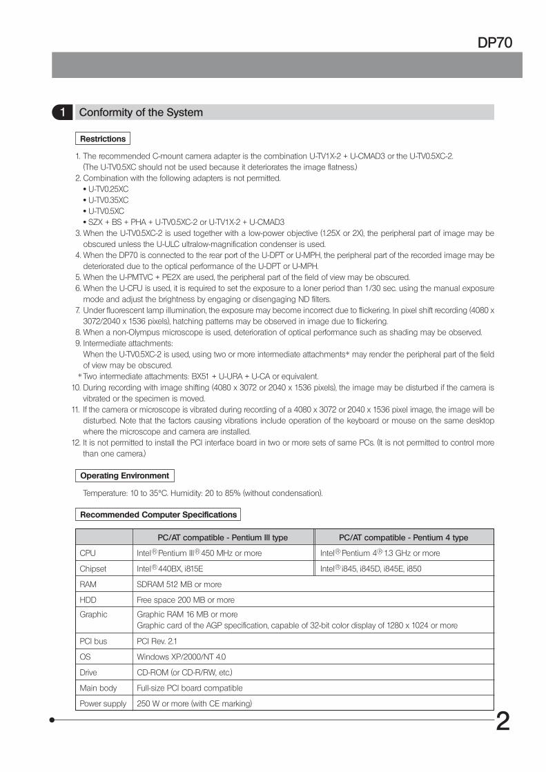
Temperature: 10 to 35°C. Humidity: 20 to 85% (without condensation).
Recommended Computer Specifications
1 Conformity of the System
10. During recording with image shifting (4080 x 3072 or 2040 x 1536 pixels), the image may be disturbed if the camera isvibrated or the specimen is moved.
11. If the camera or microscope is vibrated during recording of a 4080 x 3072 or 2040 x 1536 pixel image, the image will bedisturbed. Note that the factors causing vibrations include operation of the keyboard or mouse on the same desktopwhere the microscope and camera are installed.
12. It is not permitted to install the PCI interface board in two or more sets of same PCs. (It is not permitted to control morethan one camera.)
PC/AT compatible - Pentium III type PC/AT compatible - Pentium 4 type
CPU Intel R Pentium III R 450 MHz or more Intel R Pentium 4 R 1.3 GHz or more
Chipset Intel R 440BX, i815E Intel R i845, i845D, i845E, i850
RAM SDRAM 512 MB or more
HDD Free space 200 MB or more
Graphic Graphic RAM 16 MB or moreGraphic card of the AGP specification, capable of 32-bit color display of 1280 x 1024 or more
PCI bus PCI Rev. 2.1
OS Windows XP/2000/NT 4.0
Drive CD-ROM (or CD-R/RW, etc.)
Main body Full-size PCI board compatible
Power supply 250 W or more (with CE marking)
3
1. PC model< PC/AT compatible machine > The PC should meet the above specifications. The recommended models are as follows.DELL R : DIMENSION Series, PRECISION Series.
2. PCI interface board sizeThe PC should be a tower or middle-tower model capable of accepting a full-size PCI board. The space requirement isPCI Rev. 2.1 “full size x 1” + “Half size s 1” (*1).*1: The slot for inserting the PCI board and a half-size space of the adjacent slot are required.
3. CPUWe do not guarantee operation if the PC uses a CPU other than Pentium III or Pentium 4 or a chipset other than an Intelchipset.
4. PCI board installation in other slotsThe PCI board can be used simultaneously with an SCSI card or LAN card.It cannot be used simultaneously with a video capture card (because this occupies the PCI bus).
5. HD free spaceThe HD free space refers to the space that does not cause a special problem even when the system is installed or run.The space required for saving an image file in the HDD is slightly more than 4 MB with a 1360 x 1024-pixel (24-bit)non-compressed image and slightly more than 38 MB with a 4080 x 3072-pixel (24-bit) non-compressed image. Inconsequence, the HDD should also provide a considerably large space for saving these image files.
6. Graphic cardThe maximum frame rate for live image (15 frames/sec.) may not be assured depending on the type of the graphic cardused.< Recommended graphic cards >Matrox R : Millennium G450/G550 Series (AGP specification)
32-bit color mode of 1280 x 1024 or more is recommended.
DP70
4
1. Clean all glass components by wiping gently with gauze. To remove fingerprints or oil smudges, wipe with gauze slightlymoistened with a mixture of ether (70%) and alcohol (30%).Since solvents such as ether and alcohol are highly flammable, they must be handled carefully. Be sure to keepthese chemicals away from open flames or potential sources of electrical sparks —— for example, electricalequipment that is being switched on or off. Also remember to always use these chemicals only in a well-venti-lated room.
2. Parts other than the glass components should be cleaned by wiping with a clean cloth. Do not use organic solvents toremove major stains. Use a soft cloth slightly moistened with a neutral detergent solution.
3. Do not disassemble any part of the camera as this could result in malfunction or reduced performance.4. When not using the camera, keep it covered with a dust cover for microscope.
2 Getting Ready
1. The camera head uses precision components. Handle it with care and avoid subjecting it to a sudden or severe impact.2. The image displayed on the monitor may be affected when it is used near equipment generating strong electromagnetic
waves. This is not a malfunction and will not affect the actual image being recorded. To avoid interference duringoperation, keep the system far from any source of electromagnetic waves.
3. When mounting the camera head on a tripod, attach it by using the DP-TRAD tripod adapter, which is separately available.4. Do not use the camera in areas where it may be subjected to direct sunlight, high temperature and humidity, dust or
vibrations. (For the operating environment conditions, see chapter 7, “SPECIFICATIONS” on page 17.)5. The camera head needs to be calibrated periodically (every 3 months as reference) for the level variations caused by the
influence of cosmic rays. For the calibration method, refer to the Camera Calibration Wizard in the Online Help in theDP70-BSW software.
4 Caution
If the camera system is used in a manner not specified by this manual, the safety of the user may be imperiled. In addition,the camera system may also be damaged. Always use the equipment as outlined in this instruction manual.
The following symbols are used to set off text in this instruction manual.: Indicates that failure to follow the instructions in the warning could result in bodily harm to the
user and/or damage to equipment (including objects in the vicinity of the equipment).# : Indicates that failure to follow the instructions could result in damage to equipment.} : Indicates commentary (for ease of operation and maintenance).
Recorded picture data may be lost (destroyed) in any of the following cases. Please note that Olympusassures no liability for loss of recorded data.
· Improper handling of the external storage device such as a FD, MO or HD by the user or athird party.
· Unauthorized servicing by the user or a third party. · Result of disconnection of the interface cable or setting the PC main switch to “ ” (OFF) in
the middle of recording or erasure (initialization) operation. · General equipment failure.
3 Maintenance and Storage
Data Storage Caution
5
SYSTEM CHART
DP70
6
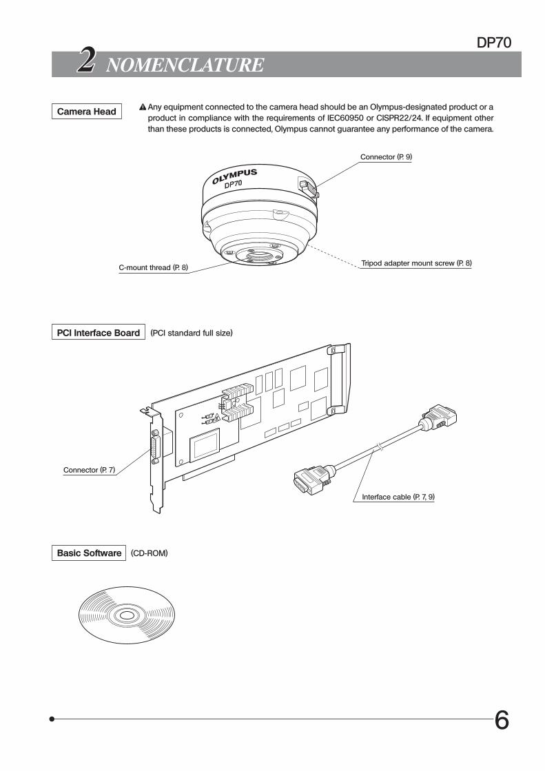
NOMENCLATURE
Camera Head Any equipment connected to the camera head should be an Olympus-designated product or aproduct in compliance with the requirements of IEC60950 or CISPR22/24. If equipment otherthan these products is connected, Olympus cannot guarantee any performance of the camera.
Connector (P. 9)
C-mount thread (P. 8)Tripod adapter mount screw (P. 8)
PCI Interface Board (PCI standard full size)
Connector (P. 7)
Interface cable (P. 7, 9)
Basic Software (CD-ROM)
7
Fig. 2
HARDWARE INSTALLATION
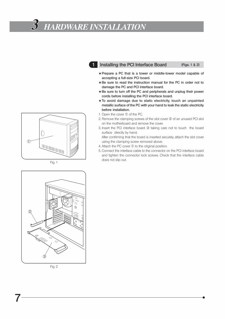
1 Installing the PCI Interface Board (Figs. 1 & 2)
#Prepare a PC that is a tower or middle-tower model capable ofaccepting a full-size PCI board.
#Be sure to read the instruction manual for the PC in order not todamage the PC and PCI interface board.
#Be sure to turn off the PC and peripherals and unplug their powercords before installing the PCI interface board.
#To avoid damage due to static electricity, touch an unpaintedmetallic surface of the PC with your hand to leak the static electricitybefore installation.
1. Open the cover @ of the PC.2. Remove the clamping screws of the slot cover ² of an unused PCI slot
on the motherboard and remove the cover.3. Insert the PCI interface board ³ taking care not to touch the board
surface directly by hand.After confirming that the board is inserted securely, attach the slot coverusing the clamping screw removed above.
4. Attach the PC cover @ to the original position.5. Connect the interface cable to the connector on the PCI interface board
and tighten the connector lock screws. Check that the interface cabledoes not slip out.
@
Fig. 1
²
³
DP70
8
Fig. 3
Fig. 4
CAUTION
³
²
@
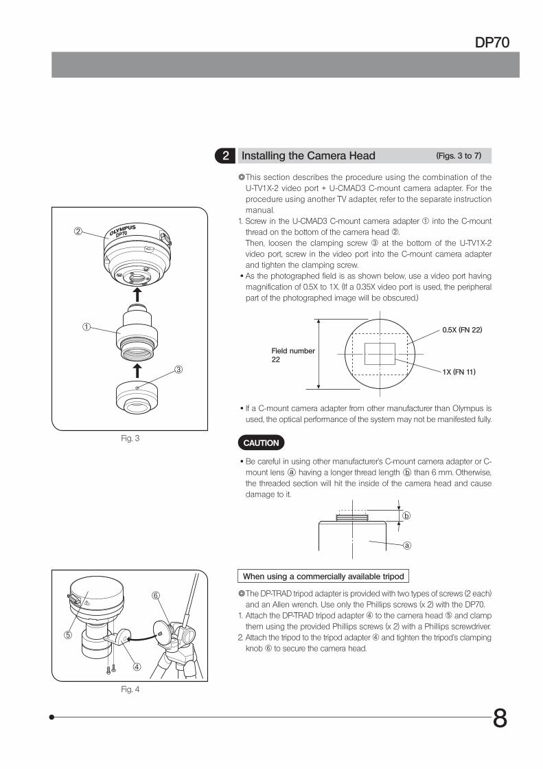
2 Installing the Camera Head (Figs. 3 to 7)
}This section describes the procedure using the combination of theU-TV1X-2 video port + U-CMAD3 C-mount camera adapter. For theprocedure using another TV adapter, refer to the separate instructionmanual.
1. Screw in the U-CMAD3 C-mount camera adapter @ into the C-mountthread on the bottom of the camera head ².Then, loosen the clamping screw ³ at the bottom of the U-TV1X-2video port, screw in the video port into the C-mount camera adapterand tighten the clamping screw.
· As the photographed field is as shown below, use a video port havingmagnification of 0.5X to 1X. (If a 0.35X video port is used, the peripheralpart of the photographed image will be obscured.)
0.5X (FN 22)
Field number22
1X (FN 11)
· If a C-mount camera adapter from other manufacturer than Olympus isused, the optical performance of the system may not be manifested fully.
· Be careful in using other manufacturer’s C-mount camera adapter or C-mount lens having a longer thread length than 6 mm. Otherwise,the threaded section will hit the inside of the camera head and causedamage to it.
When using a commercially available tripod
}The DP-TRAD tripod adapter is provided with two types of screws (2 each)and an Allen wrench. Use only the Phillips screws (x 2) with the DP70.
1. Attach the DP-TRAD tripod adapter | to the camera head ƒ and clampthem using the provided Phillips screws (x 2) with a Phillips screwdriver.
2. Attach the tripod to the tripod adapter | and tighten the tripod’s clampingknob … to secure the camera head.
|
ƒ
…
9
Fig. 6
Fig. 5
Fig. 7
@²
³
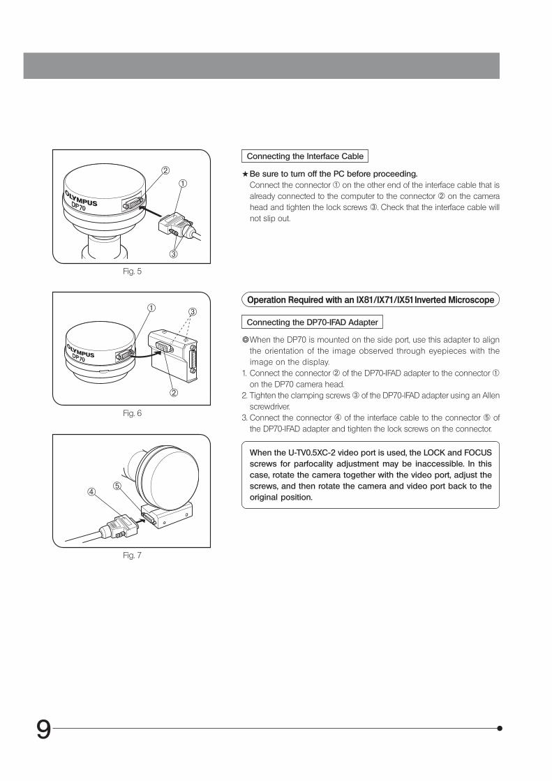
Connecting the Interface Cable
#Be sure to turn off the PC before proceeding.Connect the connector @ on the other end of the interface cable that isalready connected to the computer to the connector ² on the camerahead and tighten the lock screws ³. Check that the interface cable willnot slip out.
Operation Required with an IX81/IX71/IX51 Inverted Microscope
Connecting the DP70-IFAD Adapter
}When the DP70 is mounted on the side port, use this adapter to alignthe orientation of the image observed through eyepieces with theimage on the display.
1. Connect the connector ² of the DP70-IFAD adapter to the connector @on the DP70 camera head.
2. Tighten the clamping screws ³ of the DP70-IFAD adapter using an Allenscrewdriver.
3. Connect the connector | of the interface cable to the connector ƒ ofthe DP70-IFAD adapter and tighten the lock screws on the connector.
When the U-TV0.5XC-2 video port is used, the LOCK and FOCUSscrews for parfocality adjustment may be inaccessible. In thiscase, rotate the camera together with the video port, adjust thescrews, and then rotate the camera and video port back to theoriginal position.
@
²
³
| ƒ
DP70
10
Before Installation
SOFTWARE INSTALLATION
When the OS is Windows XP
The software cannot be installed unless the user account is registered as “computer administrator”.If the user account is registered as a “Restricted account”, change it to the “Computer administrator” account.(For the user account registration, refer to the instruction manual for your PC.)
When the OS is Windows 2000 or NT 4.0
Log on as a user with the Administrator authority and make sure that you have the access rights to the following locations.(For the access rights, refer to the instruction manual for your PC.)
· Folder for installing this software. · Windows System folder and System registry.
Trademark informationWindows is a registered trademark of Microsoft Corporation.All other brand and product names are registered trademarks or trademarks of their respective owners.
11
1 Installing the Device Driver
1. Windows R XP
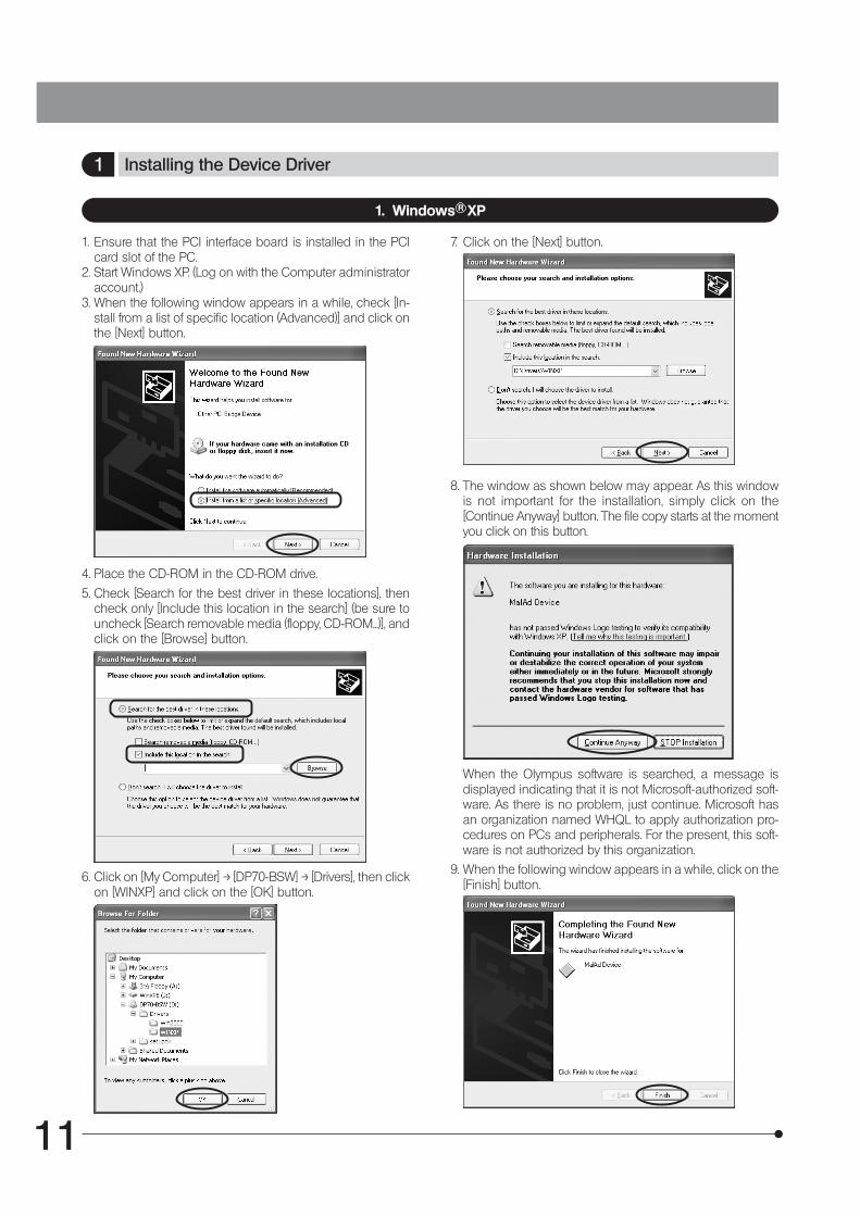
1. Ensure that the PCI interface board is installed in the PCIcard slot of the PC.
2. Start Windows XP. (Log on with the Computer administratoraccount.)
3. When the following window appears in a while, check [In-stall from a list of specific location (Advanced)] and click onthe [Next] button.
7. Click on the [Next] button.
When the Olympus software is searched, a message isdisplayed indicating that it is not Microsoft-authorized soft-ware. As there is no problem, just continue. Microsoft hasan organization named WHQL to apply authorization pro-cedures on PCs and peripherals. For the present, this soft-ware is not authorized by this organization.
9. When the following window appears in a while, click on the[Finish] button.
4. Place the CD-ROM in the CD-ROM drive.
5. Check [Search for the best driver in these locations], thencheck only [Include this location in the search] (be sure touncheck [Search removable media (floppy, CD-ROM...)], andclick on the [Browse] button.
6. Click on [My Computer] –> [DP70-BSW] –> [Drivers], then clickon [WINXP] and click on the [OK] button.
8. The window as shown below may appear. As this windowis not important for the installation, simply click on the[Continue Anyway] button. The file copy starts at the momentyou click on this button.
DP70
12
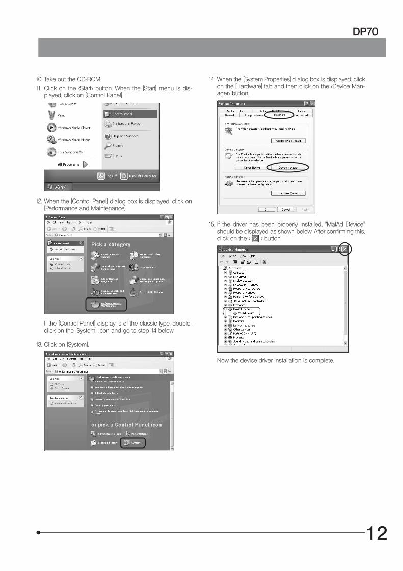
10. Take out the CD-ROM.
11. Click on the <Start> button. When the [Start] menu is dis-played, click on [Control Panel].
12. When the [Control Panel] dialog box is displayed, click on[Performance and Maintenance].
If the [Control Panel] display is of the classic type, double-click on the [System] icon and go to step 14 below.
13. Click on [System].
14. When the [System Properties] dialog box is displayed, clickon the [Hardware] tab and then click on the <Device Man-ager> button.
Now the device driver installation is complete.
15. If the driver has been properly installed, “MalAd Device"should be displayed as shown below. After confirming this,click on the < > button.
13
2. Windows R 2000
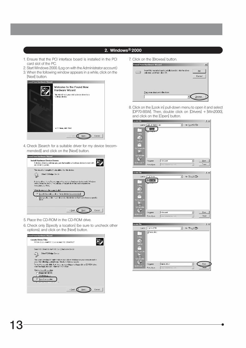
1. Ensure that the PCI interface board is installed in the PCIcard slot of the PC.
2. Start Windows 2000. (Log on with the Administrator account.)3. When the following window appears in a while, click on the
[Next] button.
4. Check [Search for a suitable driver for my device (recom-mended)] and click on the [Next] button.
5. Place the CD-ROM in the CD-ROM drive.
6. Check only [Specify a location] (be sure to uncheck otheroptions), and click on the [Next] button.
7. Click on the [Browse] button.
8. Click on the [Look in] pull-down menu to open it and select[DP70-BSW]. Then, double click on [Drivers] –> [Win2000],and click on the [Open] button.
DP70
14
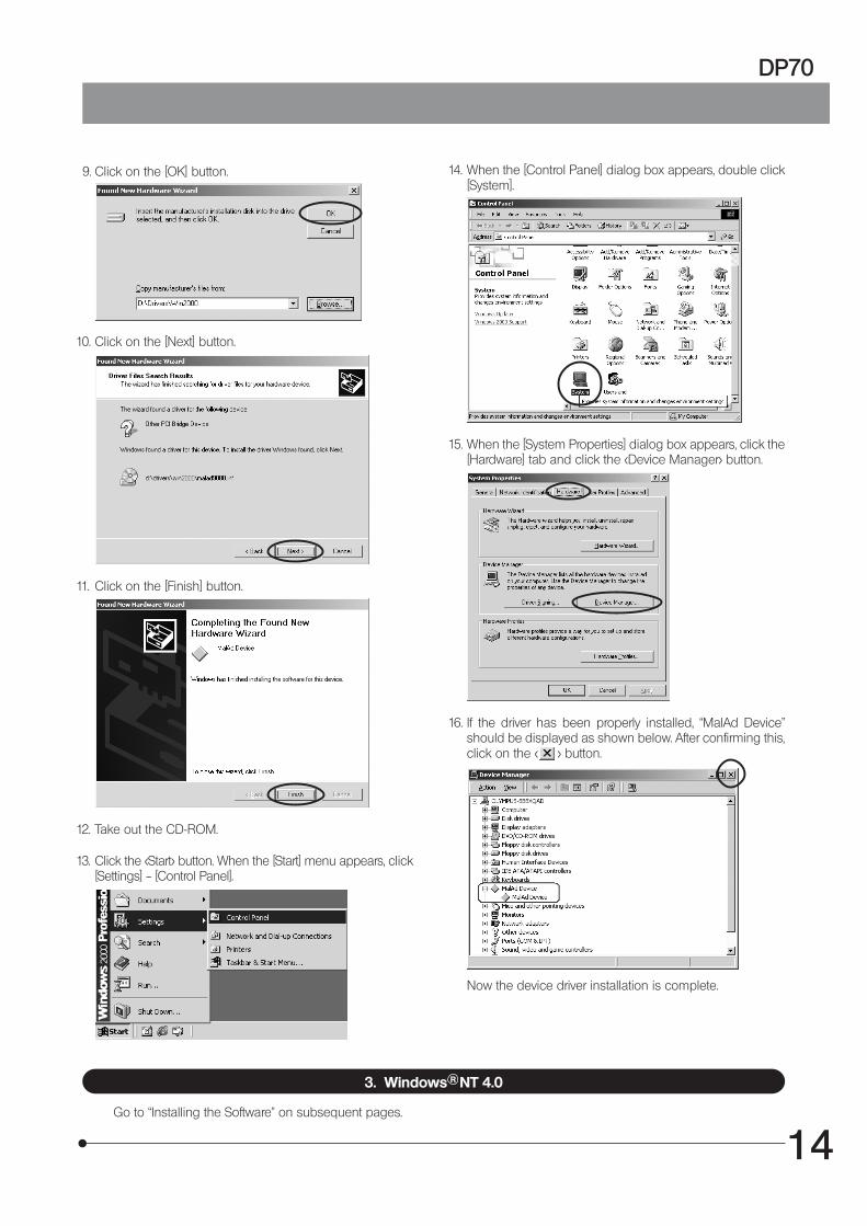
9. Click on the [OK] button.
10. Click on the [Next] button.
11. Click on the [Finish] button.
12. Take out the CD-ROM.
13. Click the <Start> button. When the [Start] menu appears, click[Settings] -- [Control Panel].
3. Windows R NT 4.0
Go to “Installing the Software” on subsequent pages.
15. When the [System Properties] dialog box appears, click the[Hardware] tab and click the <Device Manager> button.
16. If the driver has been properly installed, “MalAd Device"should be displayed as shown below. After confirming this,click on the < > button.
Now the device driver installation is complete.
14. When the [Control Panel] dialog box appears, double click[System].
15
2 Installing the Software
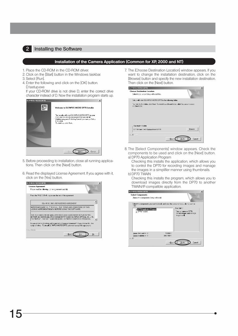
1. Place the CD-ROM in the CD-ROM driver.2. Click on the [Start] button in the Windows taskbar.3. Select [Run].4. Enter the following and click on the [OK] button.
D:\setup.exeIf your CD-ROM drive is not drive D, enter the correct drivecharacter instead of D. Now the installation program starts up.
5. Before proceeding to installation, close all running applica-tions. Then click on the [Next] button.
6. Read the displayed License Agreement. If you agree with it,click on the [Yes] button.
Installation of the Camera Application (Common for XP, 2000 and NT)
7. The [Choose Destination Location] window appears. If youwant to change the installation destination, click on the[Browse] button and specify the new installation destination.Then click on the [Next] button.
8. The [Select Components] window appears. Check thecomponents to be used and click on the [Next] button.a) DP70 Application Program
Checking this installs the application, which allows youto control the DP70 for recording images and managethe images in a simplifier manner using thumbnails.
b) DP70 TWAINChecking this installs the program, which allows you todownload images directly from the DP70 to anotherTWAIN/IF-compatible application.
DP70
16
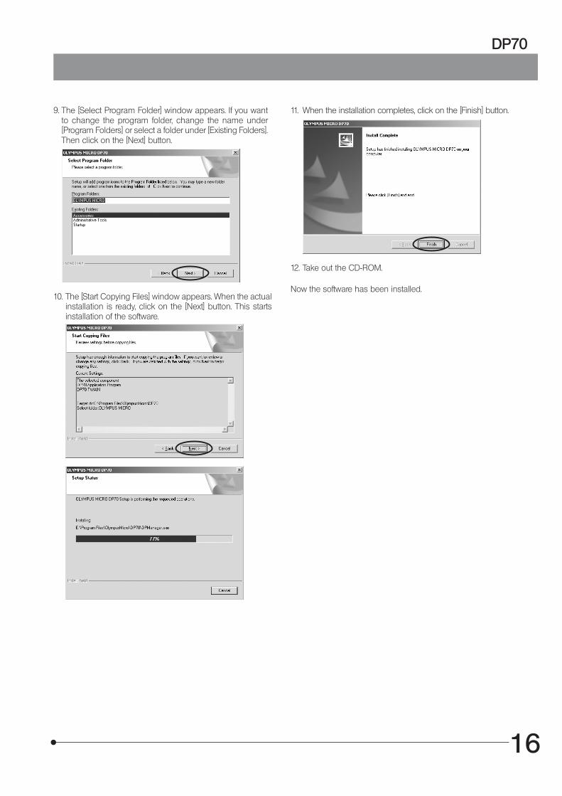
9. The [Select Program Folder] window appears. If you wantto change the program folder, change the name under[Program Folders] or select a folder under [Existing Folders].Then click on the [Next] button.
10. The [Start Copying Files] window appears. When the actualinstallation is ready, click on the [Next] button. This startsinstallation of the software.
11. When the installation completes, click on the [Finish] button.
12. Take out the CD-ROM.
Now the software has been installed.
17
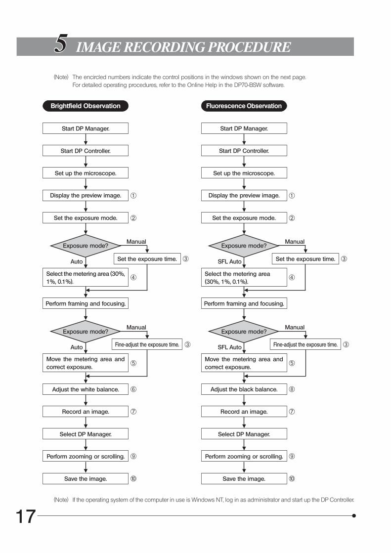
IMAGE RECORDING PROCEDURE
(Note) The encircled numbers indicate the control positions in the windows shown on the next page.For detailed operating procedures, refer to the Online Help in the DP70-BSW software.
Brightfield Observation Fluorescence Observation
Start DP Manager. Start DP Manager.
Start DP Controller. Start DP Controller.
Set up the microscope. Set up the microscope.
Display the preview image. Display the preview image.
Set the exposure mode. Set the exposure mode.
Exposure mode? Exposure mode?
Auto SFL AutoSet the exposure time. Set the exposure time.
Select the metering area (30%,1%, 0.1%).
Select the metering area(30%, 1%, 0.1%).
Perform framing and focusing. Perform framing and focusing.
Exposure mode?Manual
Manual Manual
Exposure mode?Manual
Auto SFL AutoFine-adjust the exposure time. Fine-adjust the exposure time.
Move the metering area andcorrect exposure.
Move the metering area andcorrect exposure.
Adjust the white balance. Adjust the black balance.
Record an image. Record an image.
Select DP Manager. Select DP Manager.
Perform zooming or scrolling. Perform zooming or scrolling.
Save the image. Save the image.
@
²
³
|
³
ƒ
…
†
Š
‰
@
²
³
|
³
ƒ
‡
†
Š
‰
(Note) If the operating system of the computer in use is Windows NT, log in as administrator and start up the DP Controller.
DP70
18
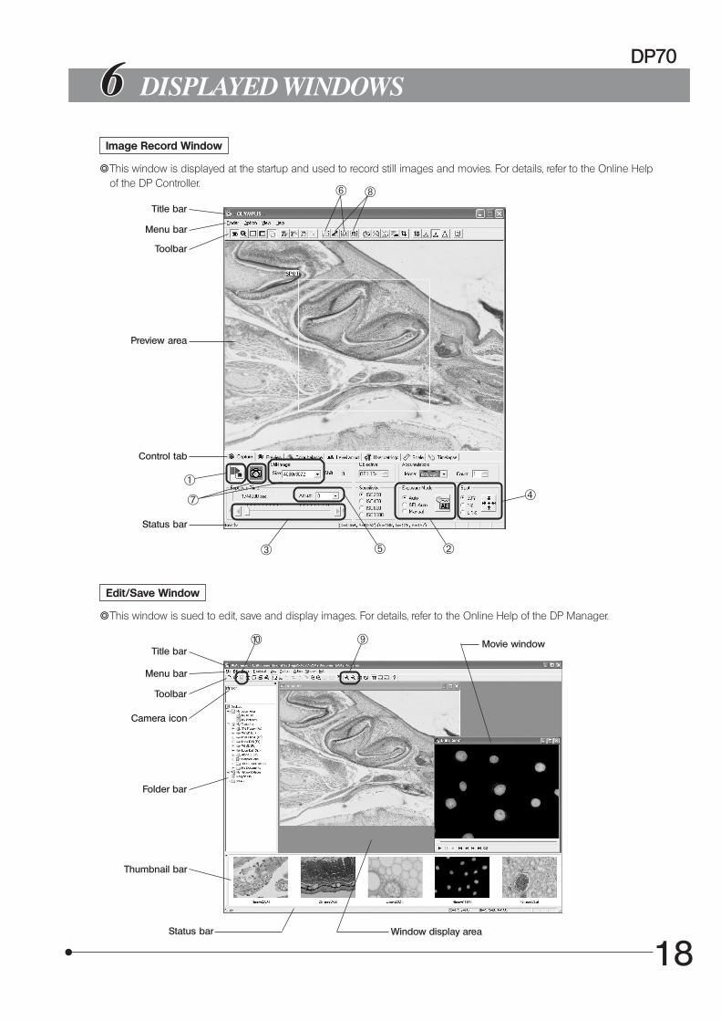
DISPLAYED WINDOWS
Image Record Window
}This window is displayed at the startup and used to record still images and movies. For details, refer to the Online Helpof the DP Controller.
Title bar
Menu bar
Toolbar
Preview area
Control tab
Status bar
Edit/Save Window
}This window is sued to edit, save and display images. For details, refer to the Online Help of the DP Manager.
Title bar
Menu bar
Toolbar
Camera icon
Folder bar
Thumbnail bar
Status bar
Movie window
Window display area
@
²³
|
ƒ
…
†
‡
‰ Š
19
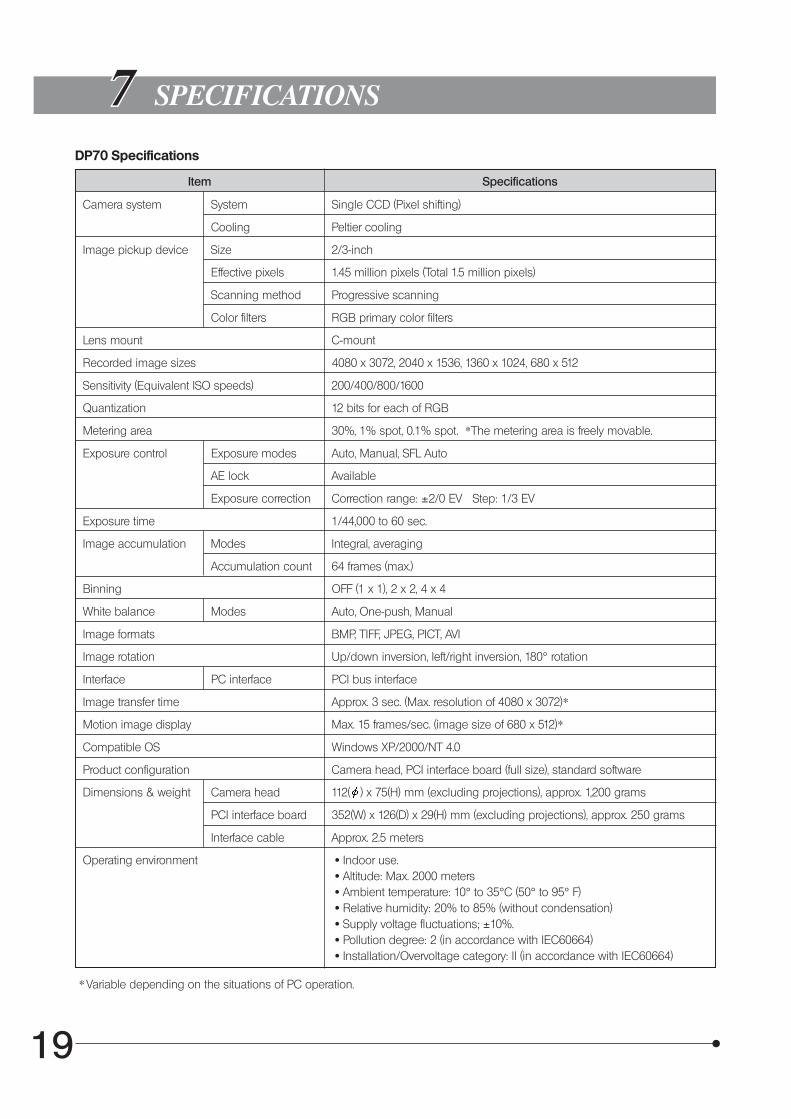
Camera system System Single CCD (Pixel shifting)
Cooling Peltier cooling
Image pickup device Size 2/3-inch
Effective pixels 1.45 million pixels (Total 1.5 million pixels)
Scanning method Progressive scanning
Color filters RGB primary color filters
Lens mount C-mount
Recorded image sizes 4080 x 3072, 2040 x 1536, 1360 x 1024, 680 x 512
Sensitivity (Equivalent ISO speeds) 200/400/800/1600
Quantization 12 bits for each of RGB
Metering area 30%, 1% spot, 0.1% spot. *The metering area is freely movable.
Exposure control Exposure modes Auto, Manual, SFL Auto
AE lock Available
Exposure correction Correction range: ±2/0 EV Step: 1/3 EV
Exposure time 1/44,000 to 60 sec.
Image accumulation Modes Integral, averaging
Accumulation count 64 frames (max.)
Binning OFF (1 x 1), 2 x 2, 4 x 4
White balance Modes Auto, One-push, Manual
Image formats BMP, TIFF, JPEG, PICT, AVI
Image rotation Up/down inversion, left/right inversion, 180° rotation
Interface PC interface PCI bus interface
Image transfer time Approx. 3 sec. (Max. resolution of 4080 x 3072)*
Motion image display Max. 15 frames/sec. (image size of 680 x 512)*
Compatible OS Windows XP/2000/NT 4.0
Product configuration Camera head, PCI interface board (full size), standard software
Dimensions & weight Camera head 112( ) x 75(H) mm (excluding projections), approx. 1,200 grams
PCI interface board 352(W) x 126(D) x 29(H) mm (excluding projections), approx. 250 grams
Interface cable Approx. 2.5 meters
SPECIFICATIONS
Item
Operating environment · Indoor use. · Altitude: Max. 2000 meters · Ambient temperature: 10° to 35°C (50° to 95° F) · Relative humidity: 20% to 85% (without condensation) · Supply voltage fluctuations; ±10%. · Pollution degree: 2 (in accordance with IEC60664) · Installation/Overvoltage category: II (in accordance with IEC60664)
* Variable depending on the situations of PC operation.
Specifications
DP70 Specifications
DP70
20
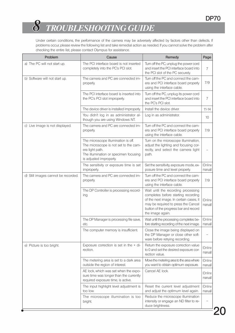
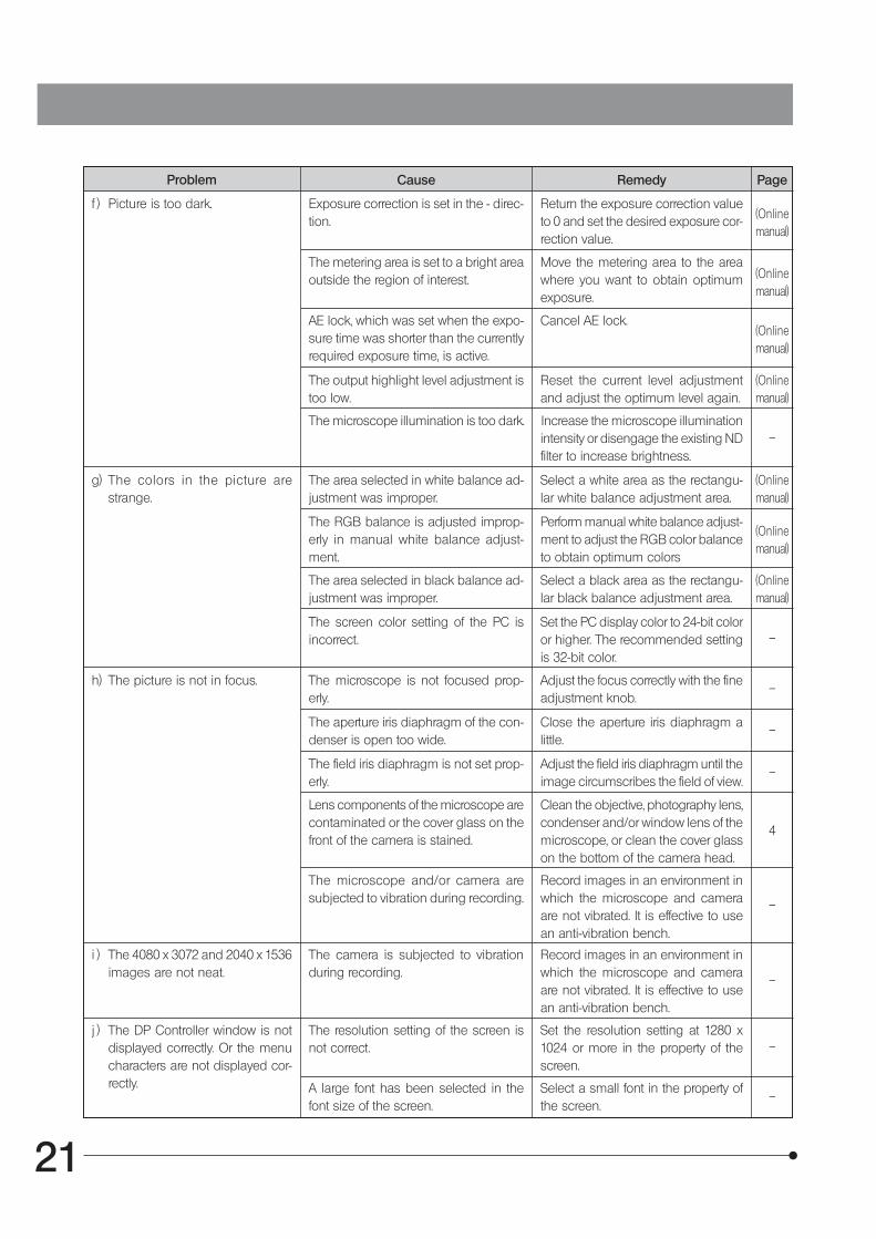
Under certain conditions, the performance of the camera may be adversely affected by factors other than defects. Ifproblems occur, please review the following list and take remedial action as needed. If you cannot solve the problem afterchecking the entire list, please contact Olympus for assistance.
TROUBLESHOOTING GUIDE
Problem Cause Remedy Page
b) Software will not start up. The camera and PC are connected im-properly.
Turn off the PC and connect the cam-era and PCI interface board properlyusing the interface cable.
The PCI interface board is inserted intothe PC’s PCI slot improperly.
Turn off the PC, unplug its power cordand insert the PCI interface board intothe PC’s PCI slot.
The device driver is installed improperly. Install the device driver.
c) Live image is not displayed. The camera and PC are connected im-properly.
Turn off the PC and connect the cam-era and PCI interface board properlyusing the interface cable.
The microscope illumination is off.The microscope is not set to the cam-era light path.The illumination or specimen focusingis adjusted improperly.
Turn on the microscope illumination,adjust the lighting and focusing cor-rectly, and select the camera lightpath.
The sensitivity or exposure time is setimproperly.
Set the sensitivity, exposure mode, ex-posure time and level properly.
(Onlinemanual)
d) Still images cannot be recorded. The camera and PC are connected im-properly.
Turn off the PC and connect the cam-era and PCI interface board properlyusing the interface cable.
The DP Controller is processing record-ing.
Wait until the recording processingcompletes before starting recordingof the next image. In certain cases, itmay be required to press the Cancelbutton of the progress bar and recordthe image again.
(Onlinemanual)
The DP Manager is processing file save,etc.
Wait until the processing completes be-fore starting recording of the next image.
(Onlinemanual)
The computer memory is insufficient. Close the image being displayed onthe DP Manager or close other soft-ware before retrying recording.
e) Picture is too bright. Exposure correction is set in the + di-rection.
Return the exposure correction valueto 0 and set the desired exposure cor-rection value.
(Onlinemanual)
The metering area is set to a dark areaoutside the region of interest.
Move the metering area to the area whereyou want to obtain optimum exposure.
(Onlinemanual)
AE lock, which was set when the expo-sure time was longer than the currentlyrequired exposure time, is active.
Cancel AE lock.(Onlinemanual)
The input highlight level adjustment istoo low.
Reset the current level adjustmentand adjust the optimum level again.
(Onlinemanual)
The microscope illumination is toobright.
Reduce the microscope illuminationintensity or engage an ND filter to re-duce brightness.
7/9
7
7/9
11-14
–
7/9
–
–
You didn't log in as administrator al-though you are using Windows NT.
Log in as administrator.10
a) The PC will not start up. The PCI interface board is not insertedcompletely into the PC’s PCI slot.
Turn off the PC, unplug the power cordand insert the PCI interface board intothe PCI slot of the PC securely.
7
21
f ) Picture is too dark.
Problem Cause Remedy Page
Exposure correction is set in the - direc-tion.
Return the exposure correction valueto 0 and set the desired exposure cor-rection value.
(Onlinemanual)
The metering area is set to a bright areaoutside the region of interest.
Move the metering area to the areawhere you want to obtain optimumexposure.
(Onlinemanual)
AE lock, which was set when the expo-sure time was shorter than the currentlyrequired exposure time, is active.
Cancel AE lock.(Onlinemanual)
The output highlight level adjustment istoo low.
Reset the current level adjustmentand adjust the optimum level again.
(Onlinemanual)
The microscope illumination is too dark. Increase the microscope illuminationintensity or disengage the existing NDfilter to increase brightness.
g) The colors in the picture arestrange.
The area selected in white balance ad-justment was improper.
Select a white area as the rectangu-lar white balance adjustment area.
(Onlinemanual)
The RGB balance is adjusted improp-erly in manual white balance adjust-ment.
Perform manual white balance adjust-ment to adjust the RGB color balanceto obtain optimum colors
(Onlinemanual)
The area selected in black balance ad-justment was improper.
Select a black area as the rectangu-lar black balance adjustment area.
(Onlinemanual)
The screen color setting of the PC isincorrect.
Set the PC display color to 24-bit coloror higher. The recommended settingis 32-bit color.
h) The picture is not in focus. The microscope is not focused prop-erly.
Adjust the focus correctly with the fineadjustment knob.
The aperture iris diaphragm of the con-denser is open too wide.
Close the aperture iris diaphragm alittle.
The field iris diaphragm is not set prop-erly.
Adjust the field iris diaphragm until theimage circumscribes the field of view.
Lens components of the microscope arecontaminated or the cover glass on thefront of the camera is stained.
Clean the objective, photography lens,condenser and/or window lens of themicroscope, or clean the cover glasson the bottom of the camera head.
The microscope and/or camera aresubjected to vibration during recording.
Record images in an environment inwhich the microscope and cameraare not vibrated. It is effective to usean anti-vibration bench.
i ) The 4080 x 3072 and 2040 x 1536images are not neat.
The camera is subjected to vibrationduring recording.
Record images in an environment inwhich the microscope and cameraare not vibrated. It is effective to usean anti-vibration bench.
–
–
–
–
–
4
–
–
j ) The DP Controller window is notdisplayed correctly. Or the menucharacters are not displayed cor-rectly.
The resolution setting of the screen isnot correct.
Set the resolution setting at 1280 x1024 or more in the property of thescreen.
–
A large font has been selected in thefont size of the screen.
Select a small font in the property ofthe screen.
–
DP70
22
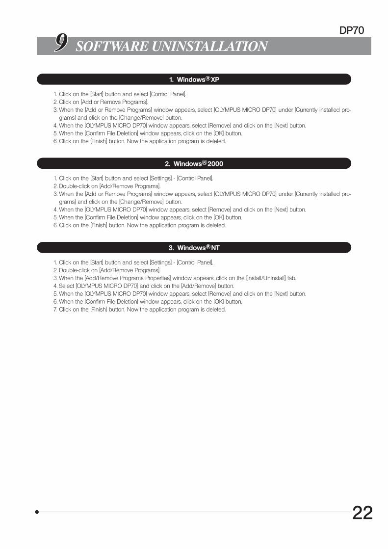
1. Windows R XP
1. Click on the [Start] button and select [Control Panel].2. Click on [Add or Remove Programs].3. When the [Add or Remove Programs] window appears, select [OLYMPUS MICRO DP70] under [Currently installed pro-
grams] and click on the [Change/Remove] button.4. When the [OLYMPUS MICRO DP70] window appears, select [Remove] and click on the [Next] button.5. When the [Confirm File Deletion] window appears, click on the [OK] button.6. Click on the [Finish] button. Now the application program is deleted.
2. Windows R 2000
SOFTWARE UNINSTALLATION
1. Click on the [Start] button and select [Settings] - [Control Panel].2. Double-click on [Add/Remove Programs].3. When the [Add or Remove Programs] window appears, select [OLYMPUS MICRO DP70] under [Currently installed pro-
grams] and click on the [Change/Remove] button.4. When the [OLYMPUS MICRO DP70] window appears, select [Remove] and click on the [Next] button.5. When the [Confirm File Deletion] window appears, click on the [OK] button.6. Click on the [Finish] button. Now the application program is deleted.
3. Windows R NT
1. Click on the [Start] button and select [Settings] - [Control Panel].2. Double-click on [Add/Remove Programs].3. When the [Add/Remove Programs Properties] window appears, click on the [Install/Uninstall] tab.4. Select [OLYMPUS MICRO DP70] and click on the [Add/Remove] button.5. When the [OLYMPUS MICRO DP70] window appears, select [Remove] and click on the [Next] button.6. When the [Confirm File Deletion] window appears, click on the [OK] button.7. Click on the [Finish] button. Now the application program is deleted.

MEMO

This publication is printed on recycled paper.
Printed in Japan 2002 11 M 025–@
2-43-2,Hatagaya, Shibuya-ku, Tokyo, Japan
Postfach 10 49 08, 20034, Hamburg, Germany
2 Corporate Center Drive, Melville, NY 11747-3157, U.S.A.
491B River Valley Road, #12-01/04 Valley Point Office Tower, Singapore 248373
2-8 Honduras Street, London EC1Y OTX, United Kingdom.
104 Ferntree Gully Road, Oakleigh, Victoria, 3166, Australia