Embed Size (px)
Citation preview
INSTRUCTIONS
DP12MICROSCOPE DIGITAL CAMERA SYSTEM
This instruction manual is for the Olympus DP12 Microscope Digital Camera System. To ensure thesafety, obtain optimum performance and familiarize yourself fully with the use of this system, werecommend that you study this manual thoroughly before operating the system. Retain thisinstruction manual in an easily accessible place near the work desk for future reference.
A X 6 4 9 3 This publication is printed on 100% recycled paper
CONTENTSDP12
6-1 Setup Using the Control Box ................................................................................................................................... 17-19
6-2 Setup/Operation Using Menus (MENU) ................................................................................................. 20-31
6-2-1 Function Setup in Record Modes 21-28
IMPORTANT — Be sure to read this section for safe use of the equipment. — 1-2
.................................................................. 15
DIGITAL IMAGE PHOTOGRAPHING/RECORDING PROCEDURE
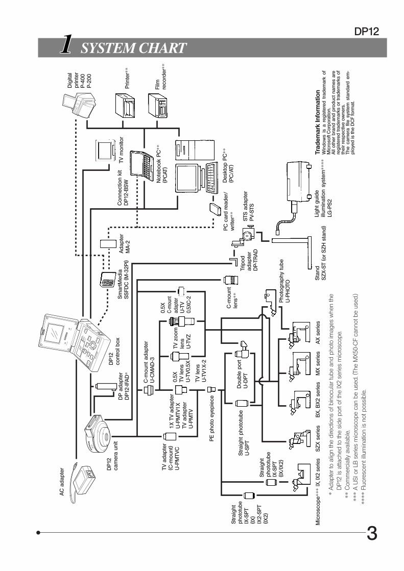
1 SYSTEM CHART
2 NOMENCLATURE
3 ASSEMBLY
4
5 BASIC OPERATIONS
4-7
8-11
12
13-16
3
1 Selecting the Record Mode (MODE, EXPOSE) ..... 13 3 Checking the Live Image ........................................ 14 5 Zooming a Played Picture ..................................... 15 7 Erasing a Single Picture (ERASE) ............... 16
2 One-Touch White Balance (OTWB) .......... 14 4 Playing a Single Picture (PLAY) ....................... 14 6 Protecting a Picture (PROTECT) .................... 16
6 SPECIAL FUNCTIONS 17-31
1 Setting the Spot Metering (SPOT) .............. 17 3 Locking the Auto Exposure Time (AE LOCK) .......... 18 5 Making a Print Reservation (PRINT) ........ 19
2 Adjusting the Exposure (EXP. ADJ.) .......... 17 4 Displaying Picture Recording Information (INFO) .... 18
1 Setting the White Balance (WB) .................. 21 3 Setting the ISO Rating (ISO) ............................... 21 5 Setting the Beep Tone ................................................ 22 7 Setting the Date/Time ................................................... 23 9 Setting the SHQ Picture Format (JPEG/TIFF) ......... 23 Displaying the Metering Range ..................... 25 Setting the Picture Display Orientation ...... 25 Setting the Focusing Indicator Display ...... 27 Setting the Video Output .......................................... 28
11
13
15
17
6-2-2 Function Setup and Operations in Play Mode 29-31
1 Setting the Auto Playback Display ........... 29 3 Printing ............................................................................................... 30
Basic Concept of Menu Setup 20
2 Selecting the Picture Quality Mode (Q) ........ 21 4 Setting the Sharpness ................................................ 22 6 ........................ 22 8 Setting the SQ Picture Size and Compression Rate .... 23 Setting the File and Folder Names ......... 24 Setting the Color Picture Display ............... 25 Setting the Scale Display ....................................... 25 Setting the Monitor Brightness ..................... 28 Resetting the Recording Setups ................ 28
10
12
14
16
18
Setting the Time of Picture Display DuringRecording/Setting the Sleep Time
2 Erasing All Pictures/Formatting SmartMedia ....... 29
PROPER SELECTION OF THE POWER SUPPLY CORD ..................................................................... 41-42
7 MONITOR DISPLAY OF PICTURES 32
1 Monitor Observation in Record Mode ..... 32 2 Monitor Observation in Play Mode ......... 32
8 PICTURE DOWNLOADING IN A PERSONAL COMPUTER 33-36
1 Connecting a PC ................................................................ 33 3 Playing Pictures on a PC ........................................ 35
2 Loading Pictures ................................................................. 34
9 ERROR CODE LIST
SPECIFICATIONS
TROUBLESHOOTING GUIDE
10
11
37
39-40
38
1
DP12
IMPORTANT
Connecting this digital camera system to an Olympus UIS or LB series microscope allows you to easilyphotograph and record the magnified images observed through the microscope.When the DP12 microscope digital camera adapter is used with a microscope from other manufacturerthan Olympus, the optical performance may not be manifested fully.
SAFETY PRECAUTIONS
1. Be sure to set the main switch of the control box to “ ” (OFF) before connecting or disconnecting any of the connectorsand plugs. Completely insert and tighten the cramping screw on the connector before setting the main switch to “ I ” (ON).
#Do not connect or disconnect the cables while the main switch is set to “ I ” (ON). Otherwise it may damage thecamera system.
2. Use the provided AC adapter only.Using another AC adapter will prevent the camera system from operating at optimum levels and may cause it tomalfunction.
3. The cords and cables are vulnerable to bending or twisting. Do not apply excessive force to them.4. To prevent toppling of the microscope, keep the total height of the microscope below 1 meter when attachments are
mounted.
Symbol Explanation
l ,
Before use, carefully read the instruction manual. Improper use could result in personal injury tothe user and/or damage to the equipment.
Indicates “ I ” (ON) or “ ” (OFF) of the main switch.
Use the specified AC adapter (6 V DC, 2.5 A).
Symbols representing an input connector, output connector and USB connector respectively.
Symbols representing recording (REC MANU. and REC AUTO modes) or playback (PLAY mode).
Write protect (PROTECT) symbol.
(ERASE) symbol.
(MENU) symbol.
Print reservation check mark.
, ,
,
Safety and Operation Symbols
The following symbols are found on the control box of the system. Study the meanings of the symbols and always usethe equipment in the safest possible manner.
2
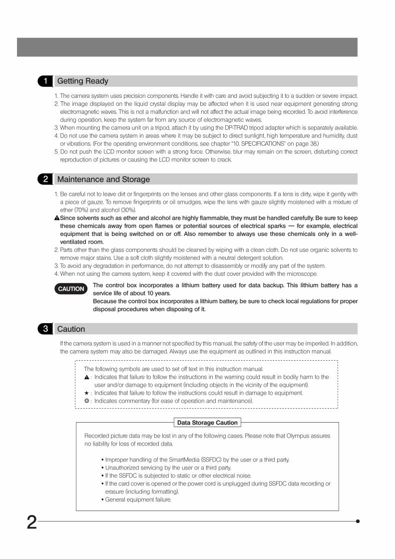
1 Getting Ready
1. The camera system uses precision components. Handle it with care and avoid subjecting it to a sudden or severe impact.2. The image displayed on the liquid crystal display may be affected when it is used near equipment generating strong
electromagnetic waves. This is not a malfunction and will not affect the actual image being recorded. To avoid interferenceduring operation, keep the system far from any source of electromagnetic waves.
3. When mounting the camera unit on a tripod, attach it by using the DP-TRAD tripod adapter which is separately available.4. Do not use the camera system in areas where it may be subject to direct sunlight, high temperature and humidity, dust
or vibrations. (For the operating environment conditions, see chapter “10. SPECIFICATIONS” on page 38.)5. Do not push the LCD monitor screen with a strong force. Otherwise, blur may remain on the screen, disturbing correct
reproduction of pictures or causing the LCD monitor screen to crack.
2 Maintenance and Storage
1. Be careful not to leave dirt or fingerprints on the lenses and other glass components. If a lens is dirty, wipe it gently witha piece of gauze. To remove fingerprints or oil smudges, wipe the lens with gauze slightly moistened with a mixture ofether (70%) and alcohol (30%).Since solvents such as ether and alcohol are highly flammable, they must be handled carefully. Be sure to keepthese chemicals away from open flames or potential sources of electrical sparks –– for example, electricalequipment that is being switched on or off. Also remember to always use these chemicals only in a well-ventilated room.
2. Parts other than the glass components should be cleaned by wiping with a clean cloth. Do not use organic solvents toremove major stains. Use a soft cloth slightly moistened with a neutral detergent solution.
3. To avoid any degradation in performance, do not attempt to disassembly or modify any part of the system.4. When not using the camera system, keep it covered with the dust cover provided with the microscope.
CAUTIONThe control box incorporates a lithium battery used for data backup. This lithium battery has aservice life of about 10 years.Because the control box incorporates a lithium battery, be sure to check local regulations for properdisposal procedures when disposing of it.
3 Caution
If the camera system is used in a manner not specified by this manual, the safety of the user may be imperiled. In addition,the camera system may also be damaged. Always use the equipment as outlined in this instruction manual.
The following symbols are used to set off text in this instruction manual.: Indicates that failure to follow the instructions in the warning could result in bodily harm to the
user and/or damage to equipment (including objects in the vicinity of the equipment).# : Indicates that failure to follow the instructions could result in damage to equipment.} : Indicates commentary (for ease of operation and maintenance).
Data Storage Caution
Recorded picture data may be lost in any of the following cases. Please note that Olympus assuresno liability for loss of recorded data.
· Improper handling of the SmartMedia (SSFDC) by the user or a third party. · Unauthorized servicing by the user or a third party. · If the SSFDC is subjected to static or other electrical noise. · If the card cover is opened or the power cord is unplugged during SSFDC data recording or
erasure (including formatting). · General equipment failure.
3
DP12
SYSTEM CHARTA
C a
dapt
er
Trad
emar
k In
form
atio
nW
ind
ows
is a
reg
iste
red
tra
dem
ark
ofM
icro
soft
Cor
por
atio
n.A
ll ot
her
bran
d an
d pr
oduc
t na
mes
are
regi
ster
ed tr
adem
arks
or
trad
emar
ks o
fth
eir r
espe
ctiv
e ow
ners
.Th
e ca
mer
a fil
e sy
stem
sta
ndar
d e
m-
plo
yed
is th
e D
CF
form
at.
*Ad
apte
r to
alig
n th
e di
rect
ions
of b
inoc
ular
tube
and
pho
to im
ages
whe
n th
eD
P12
is a
ttach
ed to
the
side
por
t of t
he IX
2 se
ries
mic
rosc
ope.
**C
omm
erci
ally
ava
ilabl
e.**
*A
USI
or L
B s
erie
s m
icro
scop
e ca
n be
use
d. (T
he M
X50-
CF
cann
ot b
e us
ed.)
****
Fluo
resc
ent i
llum
inat
ion
is n
ot p
ossi
ble.
DP
12ca
mer
a un
itD
P12
cont
rol b
oxS
mar
tMed
iaS
SFD
C (M
-32P
I)A
dap
ter
MA
-2TV
mon
itor
Con
nect
ion
kit
DP
12-B
SW N
oteb
ook
PC
**(P
CAT
)
PC
car
d re
ader
/w
riter
**D
eskt
op P
C**
(PC
/AT)
Dig
ital
prin
ter
P-40
0P-
200
Prin
ter*
*
Film
reco
rder
**TV
ada
pter
(C-m
ount
)U
-PM
TVC
1X T
V ad
apte
rU
-PM
TV1X
TV a
dapt
erU
-PM
TV
C-m
ount
ada
pter
U-C
MA
D-3
0.5X
TV le
nsU
-TV0
.5X
TV le
nsU
-TV1
X-2
TV z
oom
lens
U-T
VZ
0.5X
C-m
ount
adap
ter
U-T
V0.
5XC
-2
PE
pho
to e
yepi
ece
Str
aigh
tp
hoto
tub
eIX
-SP
T(IX
/IX
2)
Mic
rosc
ope*
**
Str
aigh
t ph
otot
ube
U-S
PT
Dou
ble
port
U-D
PT
IX, I
X2 s
erie
sS
ZX
ser
ies
BX
, BX
2 se
ries
MX
ser
ies
AX
ser
ies
Pho
togr
aphy
tub
eU
-PH
OTO
C-m
ount
lens
**
STS
ada
pter
PV-
STS
Trip
odad
apte
rD
P-TR
AD
Sta
ndS
ZX-
ST (o
r S
ZH
sta
nd)
Ligh
t gui
deill
umin
atio
n sy
stem
****
LG-P
S2
Str
aigh
tph
otot
ube
IX-S
PT
(IX)
IX2-
SP
T(IX
2)
DP
ada
pter
DP
12-IF
AD
*
4
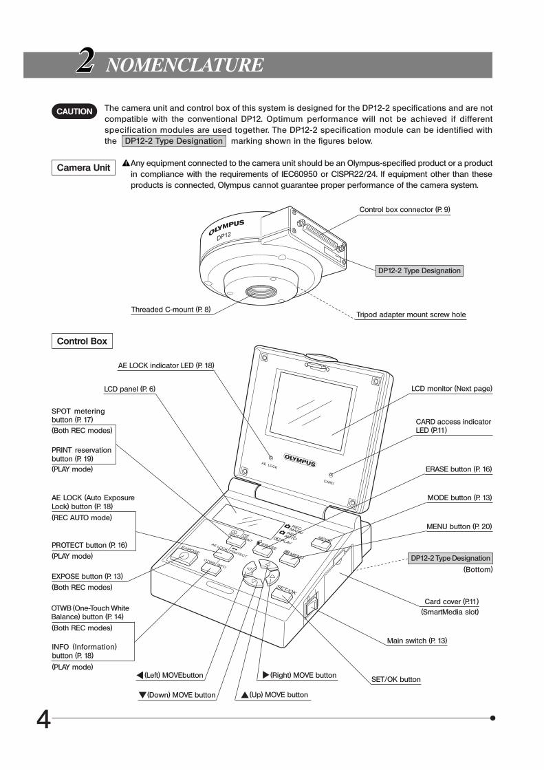
The camera unit and control box of this system is designed for the DP12-2 specifications and are notcompatible with the conventional DP12. Optimum performance will not be achieved if differentspecification modules are used together. The DP12-2 specification module can be identified withthe DP12-2 Type Designation marking shown in the figures below.
NOMENCLATURE
Camera Unit Any equipment connected to the camera unit should be an Olympus-specified product or a productin compliance with the requirements of IEC60950 or CISPR22/24. If equipment other than theseproducts is connected, Olympus cannot guarantee proper performance of the camera system.
Threaded C-mount (P. 8)
Control Box
AE LOCK indicator LED (P. 18)
Control box connector (P. 9)
Tripod adapter mount screw hole
LCD panel (P. 6)
OTWB (One-Touch WhiteBalance) button (P. 14)
(Both REC modes)
INFO (Information)button (P. 18)
(PLAY mode)
SPOT meteringbutton (P. 17)(Both REC modes)
PRINT reservationbutton (P. 19)(PLAY mode)
EXPOSE button (P. 13)
(Both REC modes)
AE LOCK (Auto ExposureLock) button (P. 18)
(REC AUTO mode)
PROTECT button (P. 16)
(PLAY mode)
(Left) MOVEbutton
(Down) MOVE button
(Right) MOVE button
(Up) MOVE button
LCD monitor (Next page)
CARD access indicatorLED (P.11)
ERASE button (P. 16)
MODE button (P. 13)
MENU button (P. 20)
Card cover (P.11)(SmartMedia slot)
Main switch (P. 13)
SET/OK button
CAUTION
DP12-2 Type Designation
DP12-2 Type Designation
(Bottom)
5
DP12
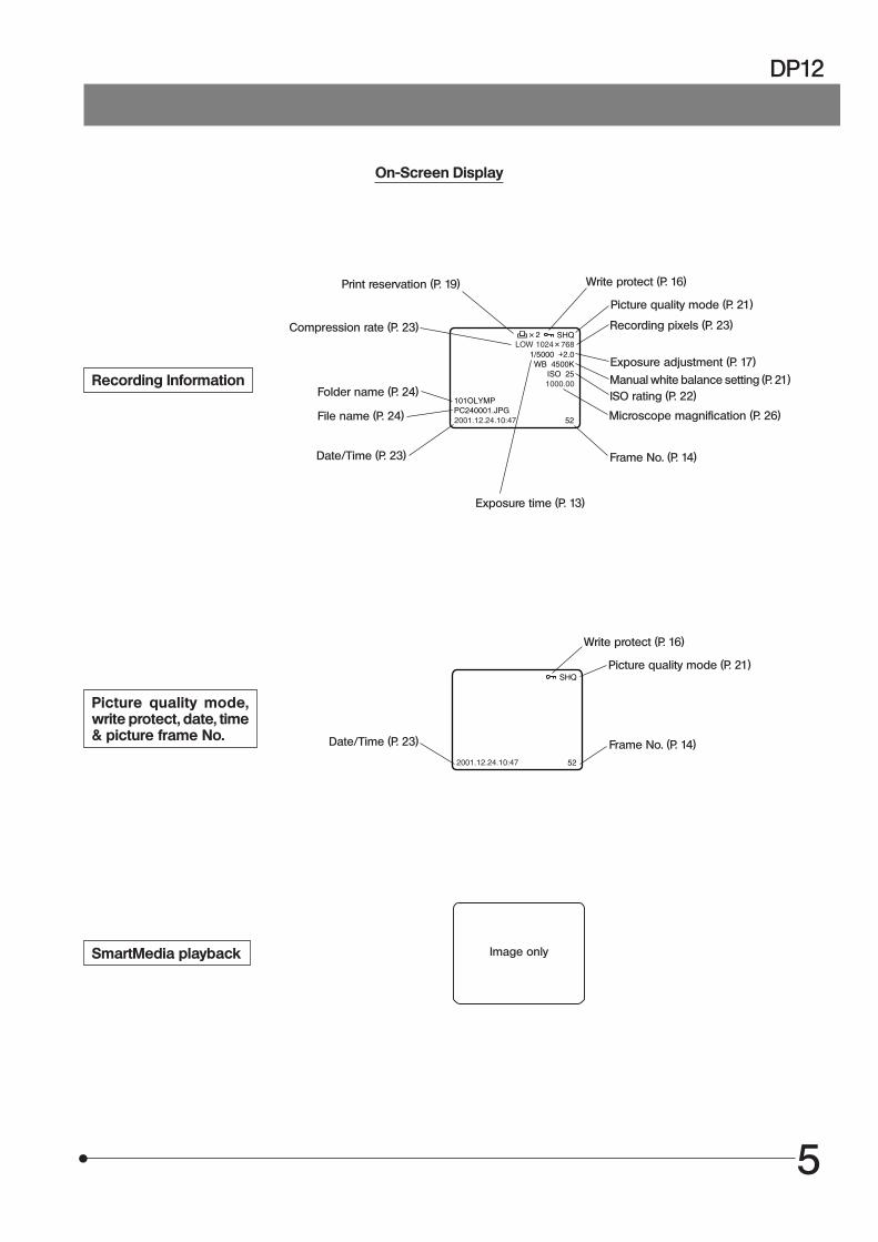
On-Screen Display
Recording Information
Microscope magnification (P. 26)
Picture quality mode,write protect, date, time& picture frame No.
SmartMedia playback
Folder name (P. 24)
File name (P. 24)
Print reservation (P. 19)
Compression rate (P. 23)
Write protect (P. 16)
Picture quality mode (P. 21)
Recording pixels (P. 23)
Exposure adjustment (P. 17)
Manual white balance setting (P. 21)ISO rating (P. 22)
Frame No. (P. 14)
Exposure time (P. 13)
Image only
Write protect (P. 16)
Picture quality mode (P. 21)
Frame No. (P. 14)Date/Time (P. 23)
Date/Time (P. 23)
6
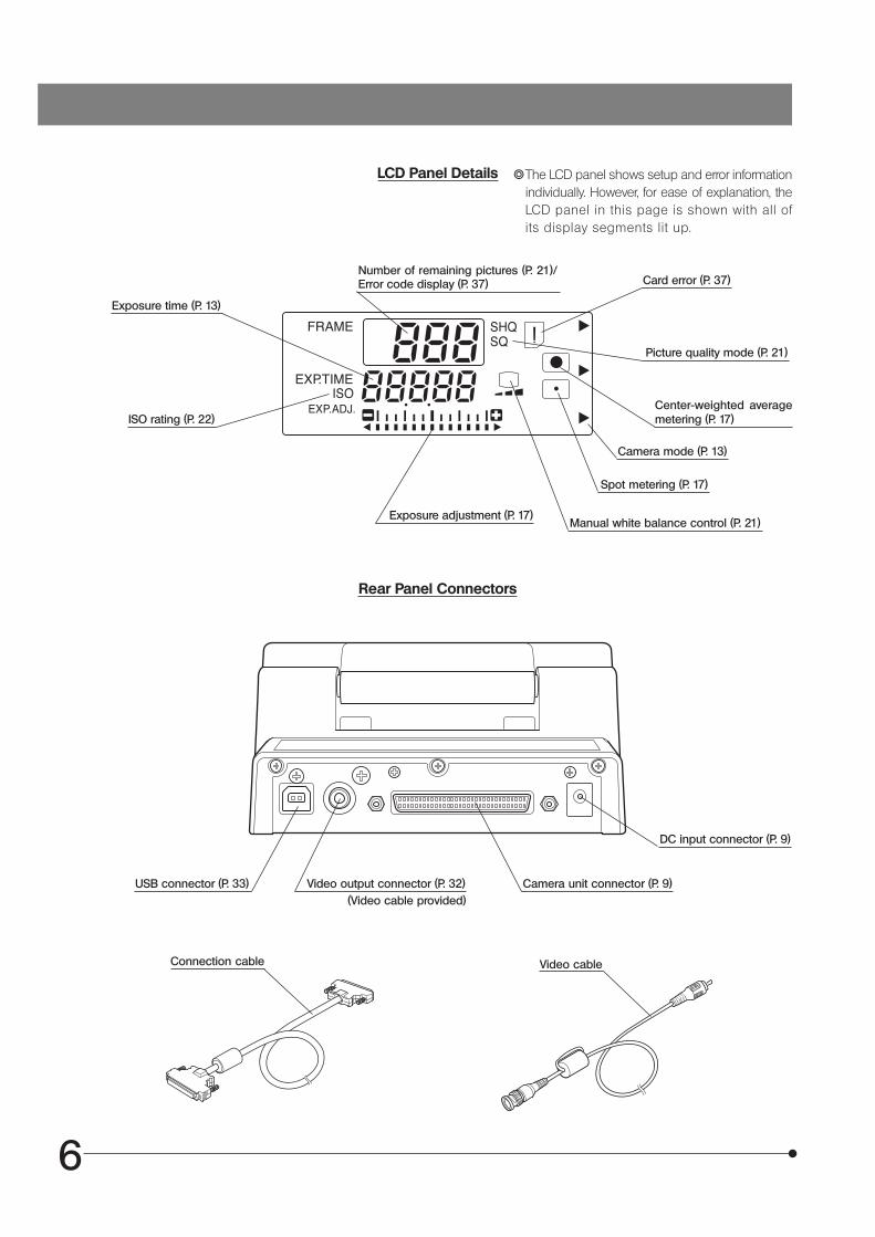
LCD Panel Details }The LCD panel shows setup and error informationindividually. However, for ease of explanation, theLCD panel in this page is shown with all ofits display segments lit up.
Exposure time (P. 13)
Rear Panel Connectors
USB connector (P. 33)
ISO rating (P. 22)
Number of remaining pictures (P. 21)/Error code display (P. 37) Card error (P. 37)
Picture quality mode (P. 21)
Center-weighted averagemetering (P. 17)
Camera mode (P. 13)
Spot metering (P. 17)
Manual white balance control (P. 21)Exposure adjustment (P. 17)
Video output connector (P. 32)(Video cable provided)
Camera unit connector (P. 9)
DC input connector (P. 9)
Video cableConnection cable

7
DP12
SmartMedia (SSFDC)M-32PI (32 MB)
}The M-16PI (16 MB), M-64PI (64 MB) and M-128PI (128 MB) SmartMedia can also be used withthe DP12.
(Note) For details, refer to the instruction manual provided with your SmartMedia.
Write protect area Index area
#The SmartMedia is a precision device. Handle it with care and avoid subject it to sudden or severe impact.Be sure not to touch its contact area.
AC Adapter
Output connector
Connection Kit (optional)DP12-BSW
PC connection cable
Contact area
Write protect seal sheet Static protection case Index labels
Input connector
CD-ROM
8
Fig. 1
Fig. 2
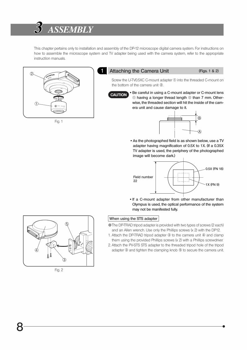
ASSEMBLY
This chapter pertains only to installation and assembly of the DP-12 microscope digital camera system. For instructions onhow to assemble the microscope system and TV adapter being used with the camera system, refer to the appropriateinstruction manuals.
1 Attaching the Camera Unit (Figs. 1 & 2)
Screw the U-TV0.5XC C-mount adapter 1 into the threaded C-mount onthe bottom of the camera unit 2.
CAUTION · Be careful in using a C-mount adapter or C-mount lens¬ having a longer thread length ® than 7 mm. Other-wise, the threaded section will hit the inside of the cam-era unit and cause damage to it.
· As the photographed field is as shown below, use a TVadapter having magnification of 0.5X to 1X. (If a 0.35XTV adapter is used, the periphery of the photographedimage will become dark.)
· If a C-mount adapter from other manufacturer thanOlympus is used, the optical performance of the systemmay not be manifested fully.
Field number22
0.5X (FN 18)
1X (FN 9)
When using the STS adapter
}The DP-TRAD tripod adapter is provided with two types of screws (2 each)and an Allen wrench. Use only the Phillips screws (x 2) with the DP12.
1. Attach the DP-TRAD tripod adapter 3 to the camera unit 4 and clampthem using the provided Phillips screws (x 2) with a Phillips screwdriver.
2. Attach the PV-STS STS adapter to the threaded tripod hole of the tripodadapter 3 and tighten the clamping knob 5 to secure the camera unit.
B
A
1
2
3
4
5
9
DP12
Fig. 3
Fig. 4
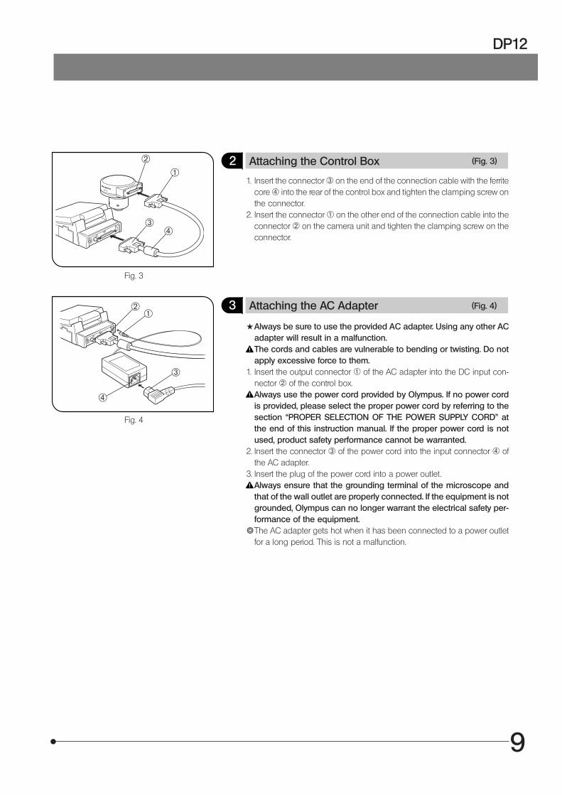
2 Attaching the Control Box (Fig. 3)
1. Insert the connector ³ on the end of the connection cable with the ferritecore | into the rear of the control box and tighten the clamping screw onthe connector.
2. Insert the connector @ on the other end of the connection cable into theconnector ² on the camera unit and tighten the clamping screw on theconnector.
3 Attaching the AC Adapter (Fig. 4)
#Always be sure to use the provided AC adapter. Using any other ACadapter will result in a malfunction.The cords and cables are vulnerable to bending or twisting. Do notapply excessive force to them.
1. Insert the output connector 1 of the AC adapter into the DC input con-nector 2 of the control box.Always use the power cord provided by Olympus. If no power cordis provided, please select the proper power cord by referring to thesection “PROPER SELECTION OF THE POWER SUPPLY CORD” atthe end of this instruction manual. If the proper power cord is notused, product safety performance cannot be warranted.
2. Insert the connector 3 of the power cord into the input connector 4 ofthe AC adapter.
3. Insert the plug of the power cord into a power outlet.Always ensure that the grounding terminal of the microscope andthat of the wall outlet are properly connected. If the equipment is notgrounded, Olympus can no longer warrant the electrical safety per-formance of the equipment.
}The AC adapter gets hot when it has been connected to a power outletfor a long period. This is not a malfunction.
12
3
12
3
4
4
10
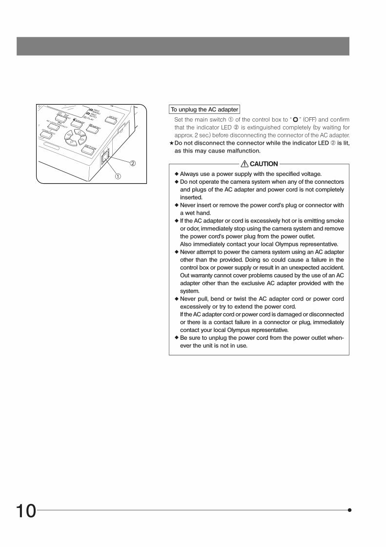
To unplug the AC adapter
Set the main switch @ of the control box to “ ” (OFF) and confirmthat the indicator LED ² is extinguished completely (by waiting forapprox. 2 sec.) before disconnecting the connector of the AC adapter.
#Do not disconnect the connector while the indicator LED ² is lit,as this may cause malfunction.
CAUTION
Always use a power supply with the specified voltage.Do not operate the camera system when any of the connectorsand plugs of the AC adapter and power cord is not completelyinserted.Never insert or remove the power cord’s plug or connector witha wet hand.If the AC adapter or cord is excessively hot or is emitting smokeor odor, immediately stop using the camera system and removethe power cord’s power plug from the power outlet.Also immediately contact your local Olympus representative.Never attempt to power the camera system using an AC adapterother than the provided. Doing so could cause a failure in thecontrol box or power supply or result in an unexpected accident.Out warranty cannot cover problems caused by the use of an ACadapter other than the exclusive AC adapter provided with thesystem.Never pull, bend or twist the AC adapter cord or power cordexcessively or try to extend the power cord.If the AC adapter cord or power cord is damaged or disconnectedor there is a contact failure in a connector or plug, immediatelycontact your local Olympus representative.Be sure to unplug the power cord from the power outlet when-ever the unit is not in use.
1
2
11
DP12
Fig. 5
Fig. 6
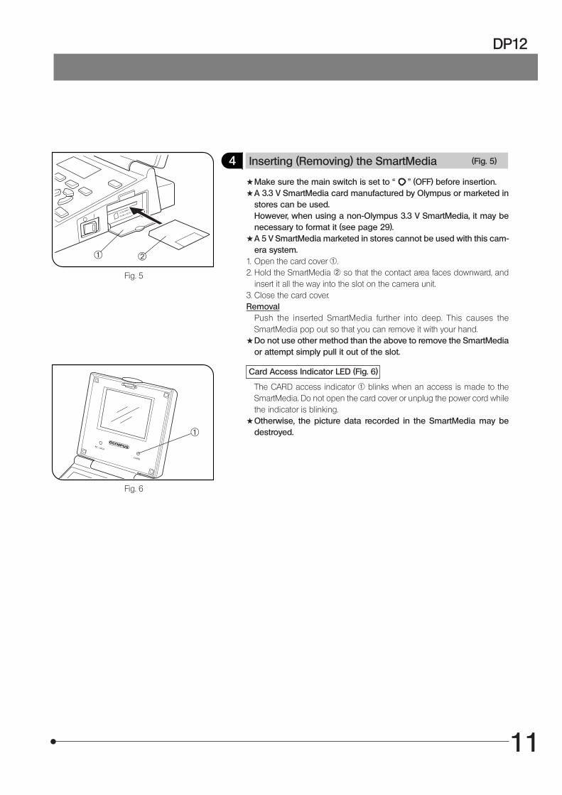
4 Inserting (Removing) the SmartMedia (Fig. 5)
#Make sure the main switch is set to “ " (OFF) before insertion.#A 3.3 V SmartMedia card manufactured by Olympus or marketed in
stores can be used.However, when using a non-Olympus 3.3 V SmartMedia, it may benecessary to format it (see page 29).
#A 5 V SmartMedia marketed in stores cannot be used with this cam-era system.
1. Open the card cover 1.2. Hold the SmartMedia 2 so that the contact area faces downward, and
insert it all the way into the slot on the camera unit.3. Close the card cover.Removal
Push the inserted SmartMedia further into deep. This causes theSmartMedia pop out so that you can remove it with your hand.
#Do not use other method than the above to remove the SmartMediaor attempt simply pull it out of the slot.
Card Access Indicator LED (Fig. 6)
The CARD access indicator 1 blinks when an access is made to theSmartMedia. Do not open the card cover or unplug the power cord whilethe indicator is blinking.
#Otherwise, the picture data recorded in the SmartMedia may bedestroyed.
1 2
1
12
DIGITAL IMAGE PHOTOGRAPHING/RECORDING PROCEDURE
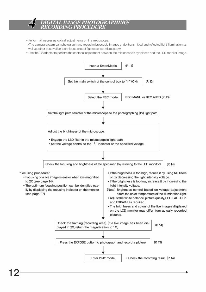
· Perform all necessary optical adjustments on the microscope.(The camera system can photograph and record microscopic images under transmitted and reflected light illumination aswell as other observation techniques except fluorescence microscopy.)
· Use the TV adapter to perform the confocal adjustment between the microscope’s eyepieces and the LCD monitor image.
Insert a SmartMedia. (P. 11)
Set the main switch of the control box to “ I ” (ON). (P. 13)
Select the REC mode. REC MANU or REC AUTO (P. 13)
Set the light path selector of the microscope to the photographing (TV) light path.
Adjust the brightness of the microscope.
· Engage the LBD filter in the microscope’s light path. · Set the voltage control to the indicator or the specified voltage.
Check the focusing and brightness of the specimen (by referring to the LCD monitor.) (P. 14)
“Focusing procedure” · Focusing of a live image is easier when it is magnified
to 2X (see page 14). · The optimum focusing position can be identified eas-
ily by displaying the focusing indicator on the monitor(see page 27).
· If the brightness is too high, reduce it by using ND filtersor by decreasing the light intensity voltage.
· If the brightness is too low, increase it by increasing thelight intensity voltage.
(Note) Brightness control based on voltage adjustmentalters the color temperature of the illumination light.
· Adjust the white balance, picture quality, SPOT, AE LOCKand EXP.ADJ as required.
· The brightness and colors of the live images displayedon the LCD monitor may differ from actually recordedpictures.
Check the framing (recording area). (If a live image has been dis-played in 2X, return the magnification to 1X.)
(P. 14)
Press the EXPOSE button to photograph and record a picture. (P. 13)
Enter PLAY mode. · Check the recording result. (P. 14)
13
DP12
Fig. 7 Fig. 8
Fig. 9
BASIC OPERATIONS
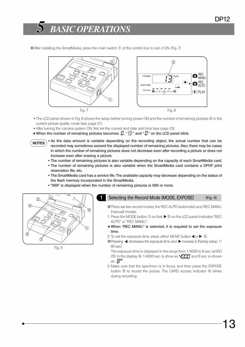
}After installing the SmartMedia, press the main switch 1 of the control box to turn it ON. (Fig. 7)
· The LCD panel shown in Fig. 8 shows the setup before turning power ON and the number of remaining pictures 2 in thecurrent picture quality mode (see page 21).
· After turning the camera system ON, first set the current and date and time (see page 23).#When the number of remaining pictures becomes , “ ” and “ ” on the LCD panel blink.
NOTES · As the data amount is variable depending on the recording object, the actual number that can be
recorded may sometimes exceed the displayed number of remaining pictures. Also, there may be casesin which the number of remaining pictures does not decrease even after recording a picture or does notincrease even after erasing a picture.
· The number of remaining pictures is also variable depending on the capacity of each SmartMedia card. · The number of remaining pictures is also variable when the SmartMedia card contains a DPOF print
reservation file, etc. · The SmartMedia card has a service life. The available capacity may decrease depending on the status of
the flash memory incorporated in the SmartMedia. · “999” is displayed when the number of remaining pictures is 999 or more.
1 Selecting the Record Mode (MODE, EXPOSE) (Fig. 9)
}There are two record modes, the REC AUTO (automatic) and REC MANU.(manual) modes.
1. Press the MODE button 1 so that 2 on the LCD panel indicates “RECAUTO” or “REC MANU.”.
#When “REC MANU.” is selected, it is required to set the exposuretime.
2. To set the exposure time, press either MOVE button or 3.}Pressing decreases the exposure time and increase it. (Factory setup: 1/
60 sec.)The exposure time is displayed in the range from 1/4000 to 8 sec. (at ISO25). In the display 4, 1/4000 sec. is show as and 8 sec. is shownas .
3. Make sure that the specimen is in focus, and then press the EXPOSEbutton 5 to record the picture. The CARD access indicator 6 blinksduring recording.
1
2
1
2
³
|
ƒ
…
14
Fig. 10
Fig. 11
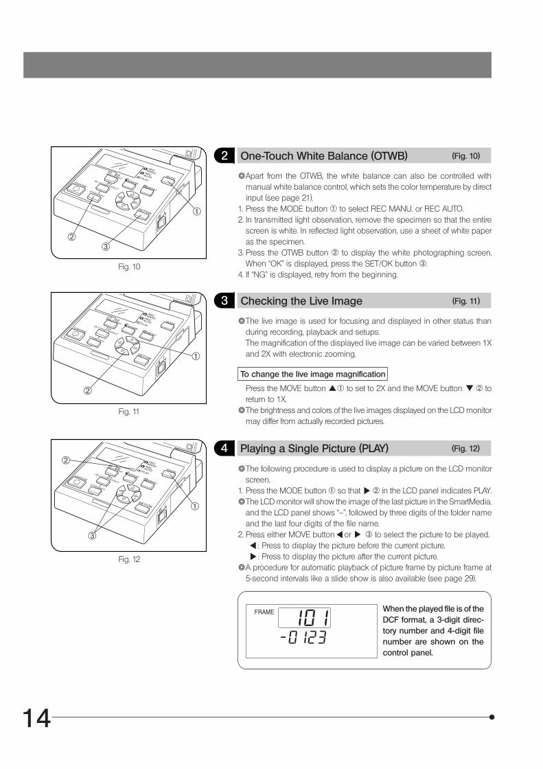
2 One-Touch White Balance (OTWB) (Fig. 10)
}Apart from the OTWB, the white balance can also be controlled withmanual white balance control, which sets the color temperature by directinput (see page 21).
1. Press the MODE button 1 to select REC MANU. or REC AUTO.2. In transmitted light observation, remove the specimen so that the entire
screen is white. In reflected light observation, use a sheet of white paperas the specimen.
3. Press the OTWB button 2 to display the white photographing screen.When “OK” is displayed, press the SET/OK button 3.
4. If “NG” is displayed, retry from the beginning.
3 Checking the Live Image (Fig. 11)
}The live image is used for focusing and displayed in other status thanduring recording, playback and setups.The magnification of the displayed live image can be varied between 1Xand 2X with electronic zooming.
To change the live image magnification
Press the MOVE button 1 to set to 2X and the MOVE button 2 toreturn to 1X.
}The brightness and colors of the live images displayed on the LCD monitormay differ from actually recorded pictures.
Fig. 12
4 Playing a Single Picture (PLAY) (Fig. 12)
}The following procedure is used to display a picture on the LCD monitorscreen.
1. Press the MODE button 1 so that 2 in the LCD panel indicates PLAY.}The LCD monitor will show the image of the last picture in the SmartMedia.
and the LCD panel shows “--”, followed by three digits of the folder nameand the last four digits of the file name.
2. Press either MOVE button or 3 to select the picture to be played. : Press to display the picture before the current picture. : Press to display the picture after the current picture.
}A procedure for automatic playback of picture frame by picture frame at5-second intervals like a slide show is also available (see page 29).
When the played file is of theDCF format, a 3-digit direc-tory number and 4-digit filenumber are shown on thecontrol panel.
1
2³
2
@
2
@
³
15
DP12
Fig. 13
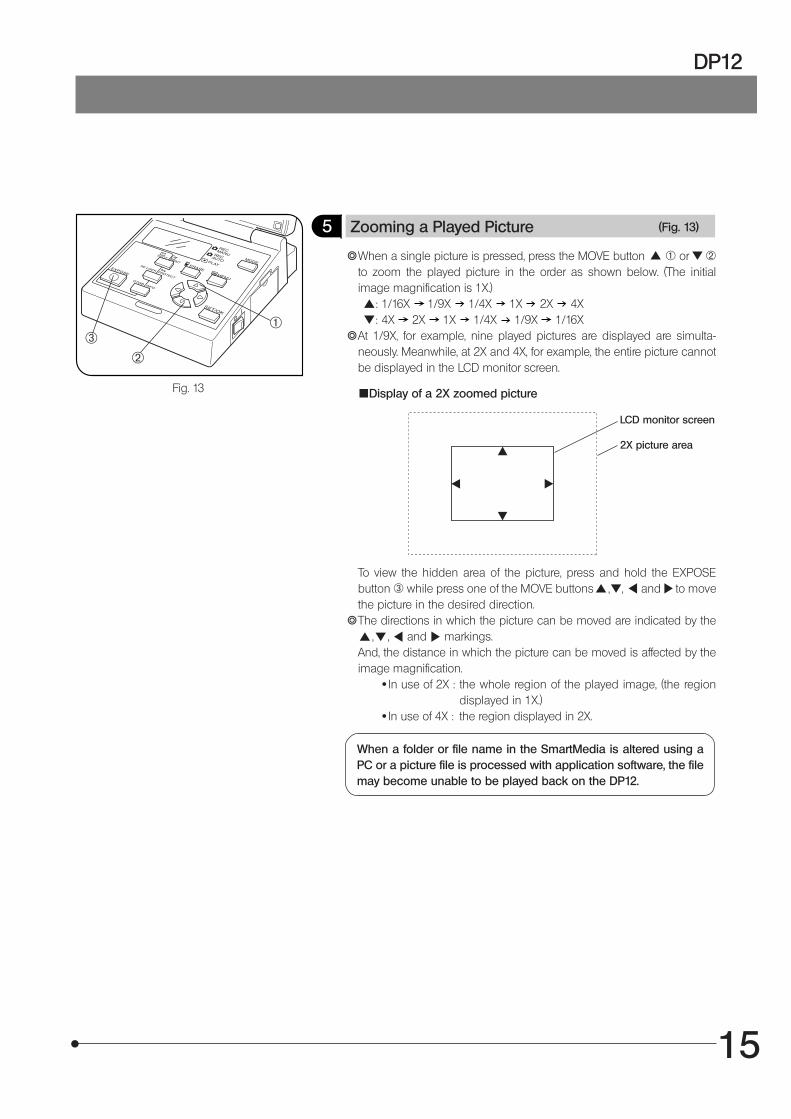
5 Zooming a Played Picture (Fig. 13)
}When a single picture is pressed, press the MOVE button 1 or 2to zoom the played picture in the order as shown below. (The initialimage magnification is 1X.) : 1/16X 1/9X 1/4X 1X 2X 4X : 4X 2X 1X 1/4X 1/9X 1/16X
}At 1/9X, for example, nine played pictures are displayed are simulta-neously. Meanwhile, at 2X and 4X, for example, the entire picture cannotbe displayed in the LCD monitor screen.
LCD monitor screen
2X picture area
To view the hidden area of the picture, press and hold the EXPOSEbutton 3 while press one of the MOVE buttons , , and to movethe picture in the desired direction.
}The directions in which the picture can be moved are indicated by the , , and markings.And, the distance in which the picture can be moved is affected by theimage magnification.
· In use of 2X : the whole region of the played image, (the regiondisplayed in 1X.)
· In use of 4X : the region displayed in 2X.
Display of a 2X zoomed picture
When a folder or file name in the SmartMedia is altered using aPC or a picture file is processed with application software, the filemay become unable to be played back on the DP12.
²
@³
16
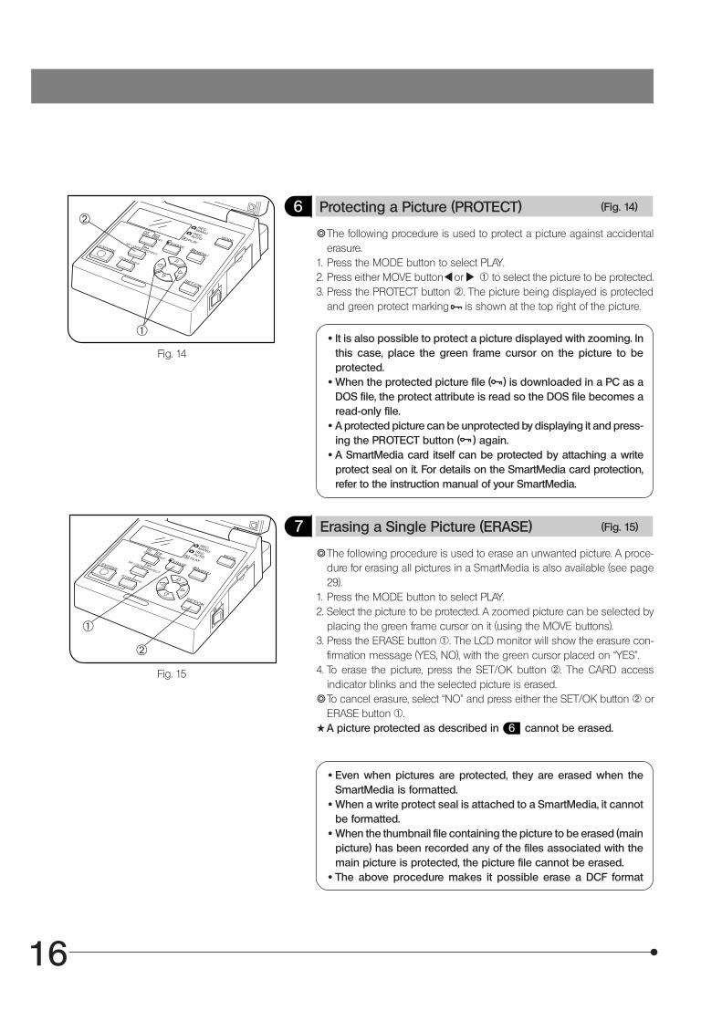
7 Erasing a Single Picture (ERASE) (Fig. 15)
}The following procedure is used to erase an unwanted picture. A proce-dure for erasing all pictures in a SmartMedia is also available (see page29).
1. Press the MODE button to select PLAY.2. Select the picture to be protected. A zoomed picture can be selected by
placing the green frame cursor on it (using the MOVE buttons).3. Press the ERASE button 1. The LCD monitor will show the erasure con-
firmation message (YES, NO), with the green cursor placed on “YES”.4. To erase the picture, press the SET/OK button 2. The CARD access
indicator blinks and the selected picture is erased.}To cancel erasure, select “NO” and press either the SET/OK button 2 or
ERASE button 1.#A picture protected as described in 6 cannot be erased.
· Even when pictures are protected, they are erased when theSmartMedia is formatted.
· When a write protect seal is attached to a SmartMedia, it cannotbe formatted.
· When the thumbnail file containing the picture to be erased (mainpicture) has been recorded any of the files associated with themain picture is protected, the picture file cannot be erased.
· The above procedure makes it possible erase a DCF format
Fig. 15
Fig. 14
}The following procedure is used to protect a picture against accidentalerasure.
1. Press the MODE button to select PLAY.2. Press either MOVE button or 1 to select the picture to be protected.3. Press the PROTECT button 2. The picture being displayed is protected
and green protect marking is shown at the top right of the picture.
6 Protecting a Picture (PROTECT) (Fig. 14)
· It is also possible to protect a picture displayed with zooming. Inthis case, place the green frame cursor on the picture to beprotected.
· When the protected picture file ( ) is downloaded in a PC as aDOS file, the protect attribute is read so the DOS file becomes aread-only file.
· A protected picture can be unprotected by displaying it and press-ing the PROTECT button ( ) again.
· A SmartMedia card itself can be protected by attaching a writeprotect seal on it. For details on the SmartMedia card protection,refer to the instruction manual of your SmartMedia.
@
²
@
²
17
DP12
Fig. 16
Fig. 17
SPECIAL FUNCTIONS
6-1 Setup Using the Control Box
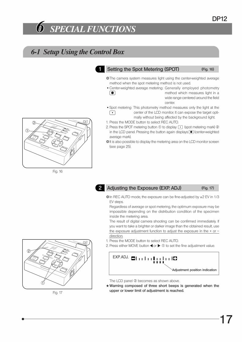
1 Setting the Spot Metering (SPOT) (Fig. 16)
}The camera system measures light using the center-weighted averagemethod when the spot metering method is not used.
· Center-weighted average metering: Generally employed photometrymethod which measures light in awide range centered around the fieldcenter.
· Spot metering: This photometry method measures only the light at thecenter of the LCD monitor. It can expose the target opti-mally without being affected by the background light.
1. Press the MODE button to select REC AUTO.2. Press the SPOT metering button 1 to display (spot metering mark) 2
in the LCD panel. Pressing the button again displays (center-weightedaverage mark).
}It is also possible to display the metering area on the LCD monitor screen(see page 25).
2 Adjusting the Exposure (EXP. ADJ) (Fig. 17)
}In REC AUTO mode, the exposure can be fine-adjusted by ±2 EV in 1/3EV steps.Regardless of average or spot metering, the optimum exposure may beimpossible depending on the distribution condition of the specimeninside the metering area.The result of digital camera shooting can be confirmed immediately. Ifyou want to take a brighter or darker image than the obtained result, usethe exposure adjustment function to adjust the exposure in the + or –direction.
1. Press the MODE button to select REC AUTO.2. Press either MOVE button or 1 to set the fine adjustment value.
²
@
@
²
The LCD panel 2 becomes as shown above.#Warning composed of three short beeps is generated when the
upper or lower limit of adjustment is reached.
Adjustment position indication
18
Fig. 18
Fig. 19
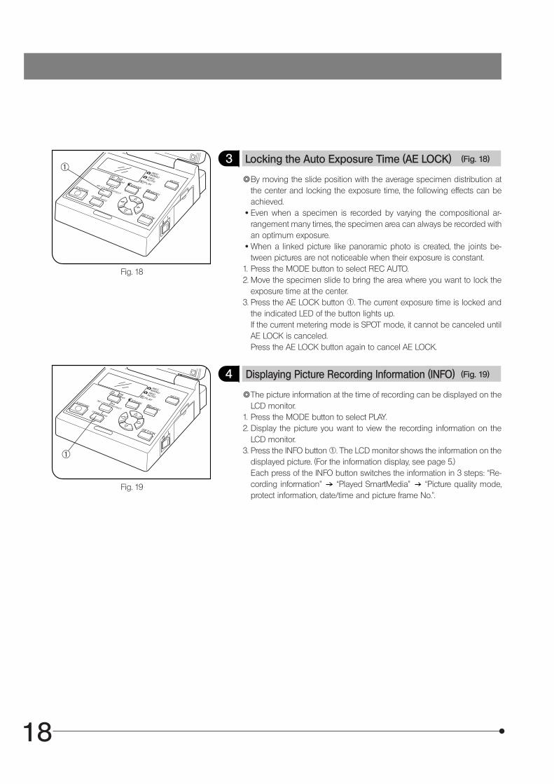
3 Locking the Auto Exposure Time (AE LOCK) (Fig. 18)
}By moving the slide position with the average specimen distribution atthe center and locking the exposure time, the following effects can beachieved.
· Even when a specimen is recorded by varying the compositional ar-rangement many times, the specimen area can always be recorded withan optimum exposure.
· When a linked picture like panoramic photo is created, the joints be-tween pictures are not noticeable when their exposure is constant.
1. Press the MODE button to select REC AUTO.2. Move the specimen slide to bring the area where you want to lock the
exposure time at the center.3. Press the AE LOCK button 1. The current exposure time is locked and
the indicated LED of the button lights up.If the current metering mode is SPOT mode, it cannot be canceled untilAE LOCK is canceled.Press the AE LOCK button again to cancel AE LOCK.
4 Displaying Picture Recording Information (INFO) (Fig. 19)
}The picture information at the time of recording can be displayed on theLCD monitor.
1. Press the MODE button to select PLAY.2. Display the picture you want to view the recording information on the
LCD monitor.3. Press the INFO button 1. The LCD monitor shows the information on the
displayed picture. (For the information display, see page 5.)Each press of the INFO button switches the information in 3 steps: “Re-cording information” “Played SmartMedia” “Picture quality mode,protect information, date/time and picture frame No.”.
@
@
19
DP12
Fig. 20
Print reservation indicator
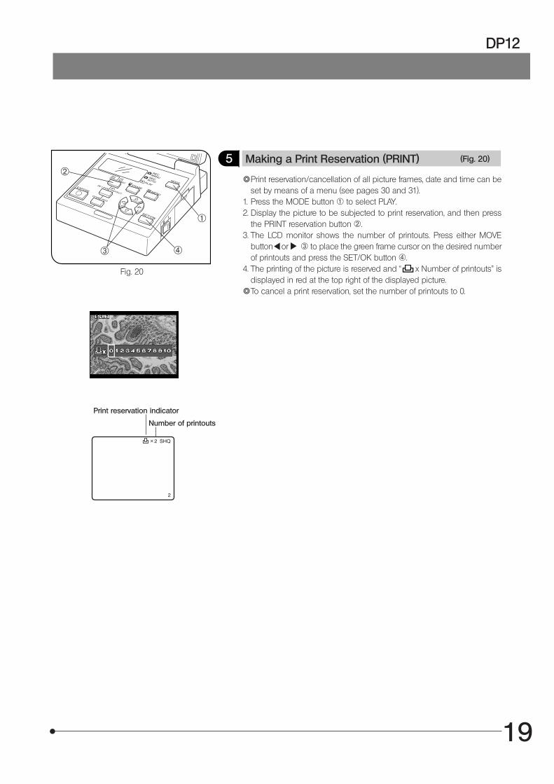
5 Making a Print Reservation (PRINT) (Fig. 20)
}Print reservation/cancellation of all picture frames, date and time can beset by means of a menu (see pages 30 and 31).
1. Press the MODE button 1 to select PLAY.2. Display the picture to be subjected to print reservation, and then press
the PRINT reservation button 2.3. The LCD monitor shows the number of printouts. Press either MOVE
button or 3 to place the green frame cursor on the desired numberof printouts and press the SET/OK button 4.
4. The printing of the picture is reserved and “ x Number of printouts” isdisplayed in red at the top right of the displayed picture.
}To cancel a print reservation, set the number of printouts to 0.
@
|³
²
Number of printouts
20
Fig. 21
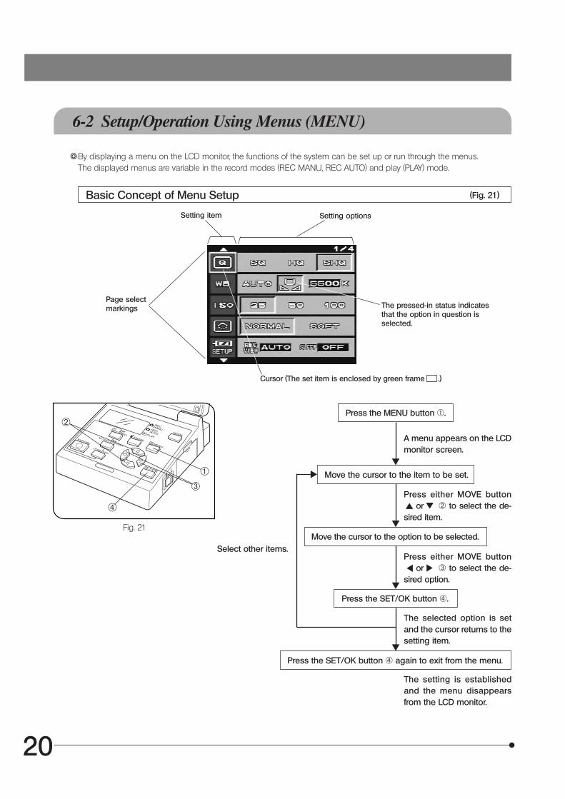
6-2 Setup/Operation Using Menus (MENU)
}By displaying a menu on the LCD monitor, the functions of the system can be set up or run through the menus.The displayed menus are variable in the record modes (REC MANU, REC AUTO) and play (PLAY) mode.
Basic Concept of Menu Setup (Fig. 21)
Page selectmarkings
Press the MENU button 1.
A menu appears on the LCDmonitor screen.
Move the cursor to the item to be set.
Press either MOVE button or 2 to select the de-sired item.
Move the cursor to the option to be selected.
Press either MOVE button or 3 to select the de-sired option.
Press the SET/OK button 4.
The selected option is setand the cursor returns to thesetting item.
Select other items.
Press the SET/OK button 4 again to exit from the menu.
The setting is establishedand the menu disappearsfrom the LCD monitor.
Setting item Setting options
The pressed-in status indicatesthat the option in question isselected.
Cursor (The set item is enclosed by green frame .)
@³
²
|
21
DP12
6-2-1 Function Setup in Record Modes
· Select REC MANU or REC AUTO with the MODE button. · Press the MENU button to display a menu on the LCD monitor. · After setting, be sure to press the SET/OK button to establish the setting.
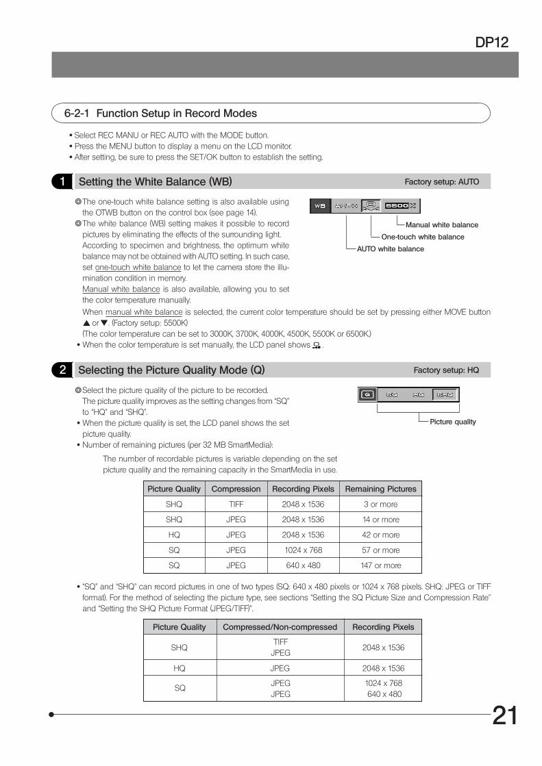
1 Setting the White Balance (WB) Factory setup: AUTO
}The one-touch white balance setting is also available usingthe OTWB button on the control box (see page 14).
}The white balance (WB) setting makes it possible to recordpictures by eliminating the effects of the surrounding light.According to specimen and brightness, the optimum whitebalance may not be obtained with AUTO setting. In such case,set one-touch white balance to let the camera store the illu-mination condition in memory.Manual white balance is also available, allowing you to setthe color temperature manually.
Manual white balance
When manual white balance is selected, the current color temperature should be set by pressing either MOVE button or . (Factory setup: 5500K)(The color temperature can be set to 3000K, 3700K, 4000K, 4500K, 5500K or 6500K.)
· When the color temperature is set manually, the LCD panel shows .
2 Selecting the Picture Quality Mode (Q) Factory setup: HQ
Picture quality
}Select the picture quality of the picture to be recorded.The picture quality improves as the setting changes from “SQ”to “HQ” and “SHQ”.
· When the picture quality is set, the LCD panel shows the setpicture quality.
· Number of remaining pictures (per 32 MB SmartMedia):
Picture Quality Compression Recording Pixels Remaining Pictures
SHQ TIFF 2048 x 1536 3 or more
SHQ JPEG 2048 x 1536 14 or more
HQ JPEG 2048 x 1536 42 or more
SQ JPEG 1024 x 768 57 or more
SQ JPEG 640 x 480 147 or more
· “SQ” and “SHQ” can record pictures in one of two types (SQ: 640 x 480 pixels or 1024 x 768 pixels. SHQ: JPEG or TIFFformat). For the method of selecting the picture type, see sections “Setting the SQ Picture Size and Compression Rate”and “Setting the SHQ Picture Format (JPEG/TIFF)”.
Picture Quality Compressed/Non-compressed Recording Pixels
SHQ 2048 x 1536TIFF
JPEG
HQ JPEG 2048 x 1536
JPEGJPEG
1024 x 768 640 x 480
SQ
AUTO white balance
One-touch white balance
The number of recordable pictures is variable depending on the setpicture quality and the remaining capacity in the SmartMedia in use.
22
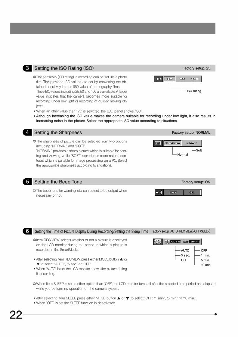
3 Setting the ISO Rating (ISO) Factory setup: 25
ISO rating
}The sensitivity (ISO rating) in recording can be set like a photofilm. The provided ISO values are set by converting the ob-tained sensitivity into an ISO value of photography films.Three ISO values including 25, 50 and 100 are available. A largervalue indicates that the camera becomes more suitable forrecording under low light or recording of quickly moving ob-jects.
· When an other value than “25” is selected, the LCD panel shows “ISO”.#Although increasing the ISO value makes the camera suitable for recording under low light, it also results in
increasing noise in the picture. Select the appropriate ISO value according to situations.
4 Setting the Sharpness Factory setup: NORMAL
Soft
}The sharpness of picture can be selected from two optionsincluding “NORMAL” and “SOFT”.“NORMAL” provides a sharp picture which is suitable for print-ing and viewing, while “SOFT” reproduces more natural con-tours which is suitable for image processing on a PC. Selectthe appropriate sharpness according to situations.
5 Setting the Beep Tone Factory setup: ON
}The beep tone for warning, etc. can be set to be output whennecessary or not.
6 Setting the Time of Picture Display During Recording/Setting the Sleep Time Factory setup: AUTO (REC VIEW)/OFF (SLEEP)
AUTO
5 sec.
OFF
OFF
1 min.
5 min.
10 min.
}Item REC VIEW selects whether or not a picture is displayedon the LCD monitor during the period in which a picture isrecorded in the SmartMedia.
· After selecting item REC VIEW, press either MOVE button or to select “AUTO”, “5 sec.” or “OFF”.
· When “AUTO” is set, the LCD monitor shows the picture duringits recording.
}When item SLEEP is set to other option than “OFF”, the LCD monitor turns off after the selected time period has elapsedwhile you perform no operation on the camera system.
· After selecting item SLEEP, press either MOVE button or to select “OFF”, “1 min.”, “5 min.” or “10 min.”. · When “OFF” is set the SLEEP function is deactivated.
Normal
23
DP12
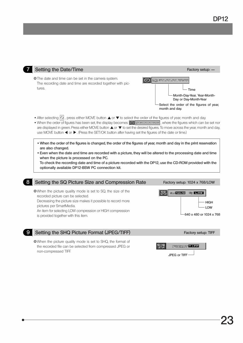
7 Setting the Date/Time Factory setup: ——
}The date and time can be set in the camera system.The recording date and time are recorded together with pic-tures. Time
· After selecting , press either MOVE button or to select the order of the figures of year, month and day. · When the order of figures has been set, the display becomes , where the figures which can be set nor
are displayed in green. Press either MOVE button or to set the desired figures. To move across the year, month and day,use MOVE button or . (Press the SET/OK button after having set the figures of the date or time.)
· When the order of the figures is changed, the order of the figures of year, month and day in the print reservationare also changed.
· Even when the date and time are recorded with a picture, they will be altered to the processing date and timewhen the picture is processed on the PC.To check the recording date and time of a picture recorded with the DP12, use the CD-ROM provided with theoptionally available DP12-BSW PC connection kit.
8 Setting the SQ Picture Size and Compression Rate Factory setup: 1024 x 768/LOW
640 x 480 or 1024 x 768
}When the picture quality mode is set to SQ, the size of therecorded picture can be selected.Decreasing the picture size makes it possible to record morepictures per SmartMedia.An item for selecting LOW compression or HIGH compressionis provided together with this item.
9 Setting the SHQ Picture Format (JPEG/TIFF) Factory setup: TIFF
JPEG or TIFF
}When the picture quality mode is set to SHQ, the format ofthe recorded file can be selected from compressed JPEG ornon-compressed TIFF.
Month-Day-Year, Year-Month-Day or Day-Month-Year
Select the order of the figures of year,month and day.
HIGH
LOW
24
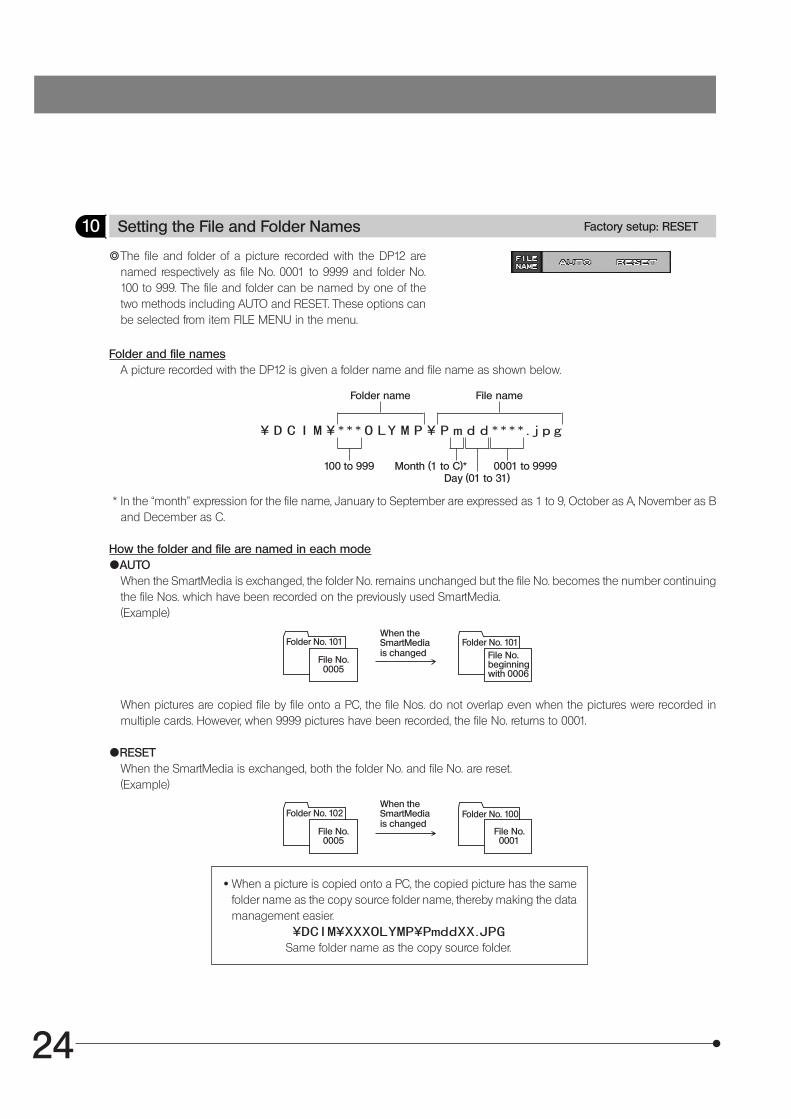
10 Setting the File and Folder Names Factory setup: RESET
}The file and folder of a picture recorded with the DP12 arenamed respectively as file No. 0001 to 9999 and folder No.100 to 999. The file and folder can be named by one of thetwo methods including AUTO and RESET. These options canbe selected from item FILE MENU in the menu.
Folder and file namesA picture recorded with the DP12 is given a folder name and file name as shown below.
* In the “month” expression for the file name, January to September are expressed as 1 to 9, October as A, November as Band December as C.
How the folder and file are named in each mode{AUTO
When the SmartMedia is exchanged, the folder No. remains unchanged but the file No. becomes the number continuingthe file Nos. which have been recorded on the previously used SmartMedia.(Example)
When pictures are copied file by file onto a PC, the file Nos. do not overlap even when the pictures were recorded inmultiple cards. However, when 9999 pictures have been recorded, the file No. returns to 0001.
{RESETWhen the SmartMedia is exchanged, both the folder No. and file No. are reset.(Example)
Folder name File name
Month (1 to C)*Day (01 to 31)
100 to 999 0001 to 9999
· When a picture is copied onto a PC, the copied picture has the samefolder name as the copy source folder name, thereby making the datamanagement easier.
Same folder name as the copy source folder.
Folder No. 101
File No.0005
When theSmartMediais changed
Folder No. 101File No.beginningwith 0006
Folder No. 102
File No.0005
When theSmartMediais changed
Folder No. 100
File No.0001
25
DP12
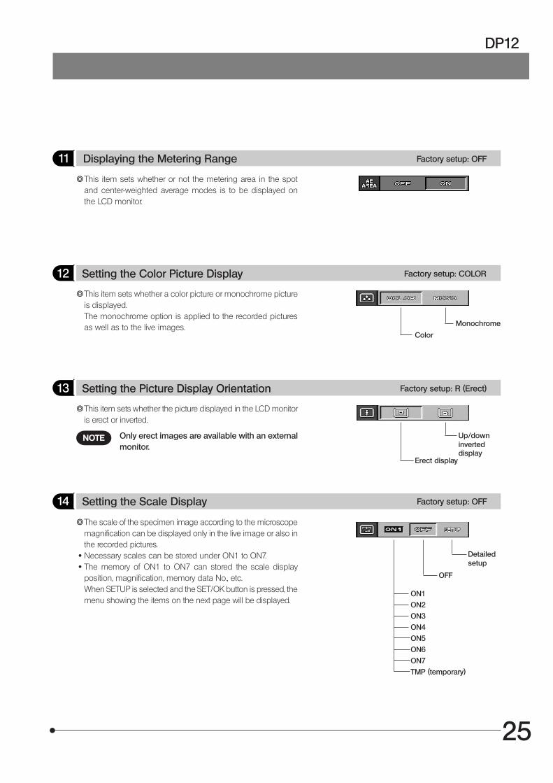
11 Displaying the Metering Range Factory setup: OFF
}This item sets whether or not the metering area in the spotand center-weighted average modes is to be displayed onthe LCD monitor.
12 Setting the Color Picture Display Factory setup: COLOR
Color
}This item sets whether a color picture or monochrome pictureis displayed.The monochrome option is applied to the recorded picturesas well as to the live images.
13 Setting the Picture Display Orientation Factory setup: R (Erect)
Erect display
}This item sets whether the picture displayed in the LCD monitoris erect or inverted.
14 Setting the Scale Display Factory setup: OFF
ON1
ON2
ON3
ON4
ON5
ON6
ON7
TMP (temporary)
}The scale of the specimen image according to the microscopemagnification can be displayed only in the live image or also inthe recorded pictures.
· Necessary scales can be stored under ON1 to ON7. · The memory of ON1 to ON7 can stored the scale display
position, magnification, memory data No., etc.When SETUP is selected and the SET/OK button is pressed, themenu showing the items on the next page will be displayed.
Monochrome
Up/downinverteddisplay
OFF
Detailedsetup
Only erect images are available with an externalmonitor.
NOTE
26
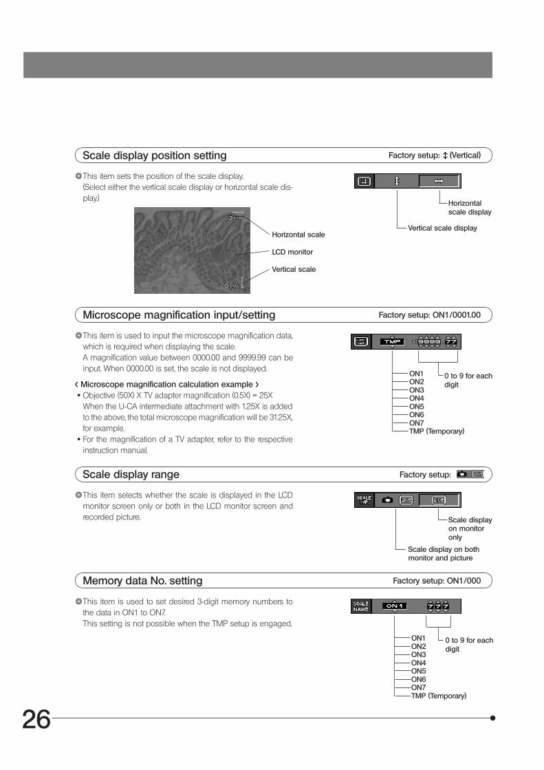
Scale display position setting Factory setup: (Vertical)
}This item sets the position of the scale display.(Select either the vertical scale display or horizontal scale dis-play.)
Vertical scale displayHorizontal scale
LCD monitor
Vertical scale
Microscope magnification input/setting Factory setup: ON1/0001.00
0 to 9 for eachdigit
}This item is used to input the microscope magnification data,which is required when displaying the scale.A magnification value between 0000.00 and 9999.99 can beinput. When 0000.00 is set, the scale is not displayed.
Scale display range Factory setup:
Scale displayon monitoronly
}This item selects whether the scale is displayed in the LCDmonitor screen only or both in the LCD monitor screen andrecorded picture.
Memory data No. setting Factory setup: ON1/000
}This item is used to set desired 3-digit memory numbers tothe data in ON1 to ON7.This setting is not possible when the TMP setup is engaged.
0 to 9 for eachdigit
Horizontalscale display
Scale display on bothmonitor and picture
ON1ON2ON3ON4ON5ON6ON7TMP (Temporary)
< Microscope magnification calculation example > · Objective (50X) X TV adapter magnification (0.5X) = 25X
When the U-CA intermediate attachment with 1.25X is addedto the above, the total microscope magnification will be 31.25X,for example.
· For the magnification of a TV adapter, refer to the respectiveinstruction manual.
ON1ON2ON3ON4ON5ON6ON7TMP (Temporary)
27
DP12
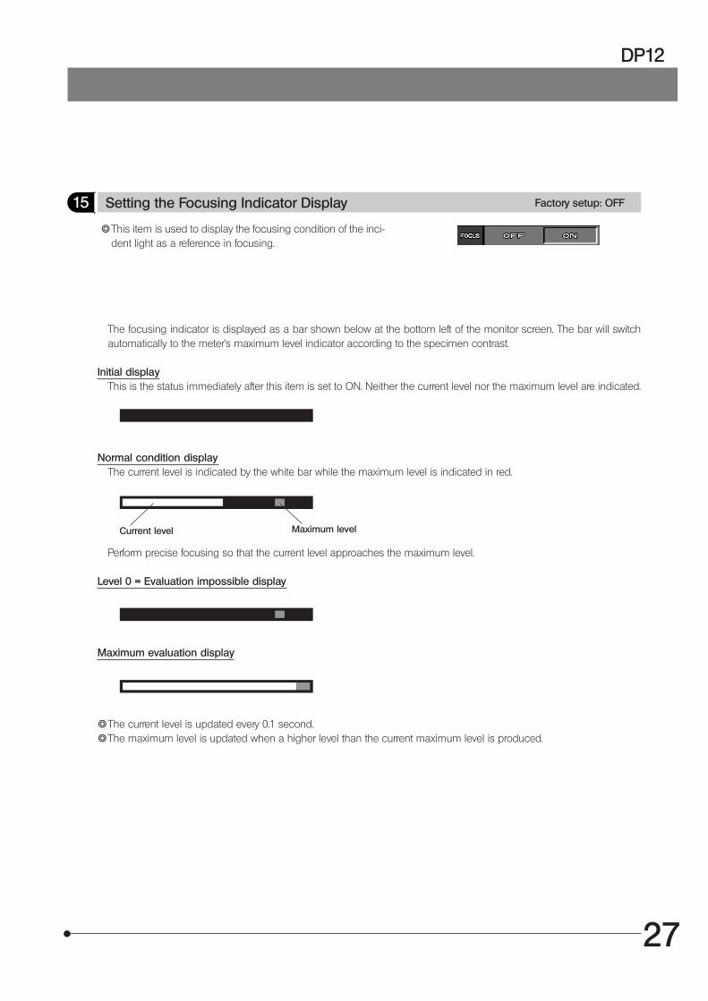
15 Setting the Focusing Indicator Display Factory setup: OFF
}This item is used to display the focusing condition of the inci-dent light as a reference in focusing.
The focusing indicator is displayed as a bar shown below at the bottom left of the monitor screen. The bar will switchautomatically to the meter's maximum level indicator according to the specimen contrast.
Initial displayThis is the status immediately after this item is set to ON. Neither the current level nor the maximum level are indicated.
Normal condition displayThe current level is indicated by the white bar while the maximum level is indicated in red.
Current level
Perform precise focusing so that the current level approaches the maximum level.
Level 0 = Evaluation impossible display
Maximum evaluation display
}The current level is updated every 0.1 second.}The maximum level is updated when a higher level than the current maximum level is produced.
Maximum level
28
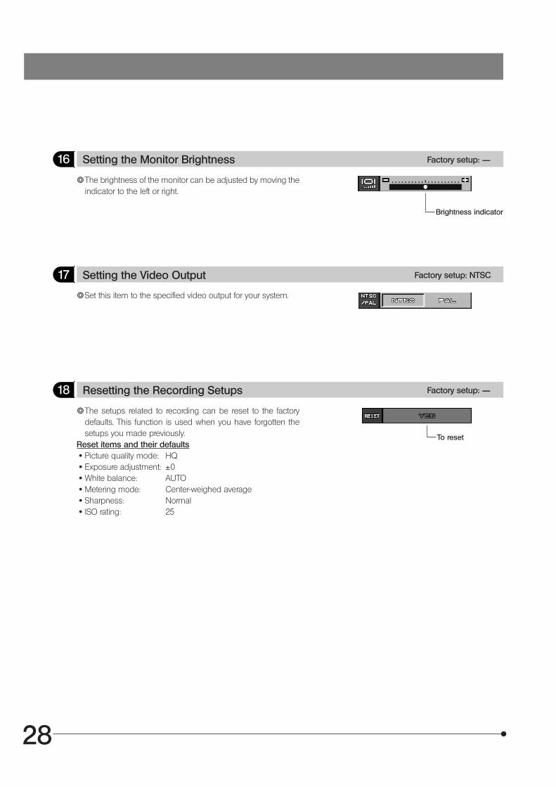
16 Setting the Monitor Brightness Factory setup: ——
Brightness indicator
}The brightness of the monitor can be adjusted by moving theindicator to the left or right.
17 Setting the Video Output Factory setup: NTSC
}Set this item to the specified video output for your system.
18 Resetting the Recording Setups Factory setup: ——
}The setups related to recording can be reset to the factorydefaults. This function is used when you have forgotten thesetups you made previously.
Reset items and their defaults · Picture quality mode: HQ · Exposure adjustment: ±0 · White balance: AUTO · Metering mode: Center-weighed average · Sharpness: Normal · ISO rating: 25
To reset
29
DP12
6-2-2 Function Setup and Operations in Play Mode
· Press the MODE button to select PLAY. · Press the MENU button to display a menu on the LCD monitor. · After setting, be sure to press the SET/OK button to establish the setting.
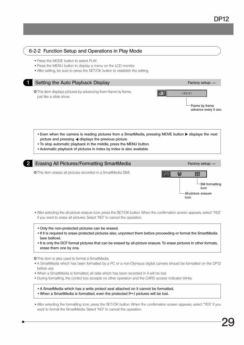
1 Setting the Auto Playback Display Factory setup: ——
}This item displays pictures by advancing them frame by frame,just like a slide show.
Frame by frameadvance every 5 sec.
· Even when the camera is reading pictures from a SmartMedia, pressing MOVE button displays the nextpicture and pressing displays the previous picture.
· To stop automatic playback in the middle, press the MENU button. · Automatic playback of pictures in index by index is also available.
2 Erasing All Pictures/Formatting SmartMedia Factory setup: ——
All-picture erasureicon
}This item erases all pictures recorded in a SmartMedia (SM).
· After selecting the all-picture erasure icon, press the SET/OK button. When the confirmation screen appears, select “YES”if you want to erase all pictures. Select “NO” to cancel the operation.
· Only the non-protected pictures can be erased. · If it is required to erase protected pictures also, unprotect them before proceeding or format the SmartMedia
(see bellow). · It is only the DCF format pictures that can be erased by all-picture erasure. To erase pictures in other formats,
erase them one by one.
}This item is also used to format a SmartMedia. · A SmartMedia which has been formatted by a PC or a non-Olympus digital camera should be formatted on the DP12
before use. · When a SmartMedia is formatted, all data which has been recorded in it will be lost. · During formatting, the control box accepts no other operation and the CARD access indicator blinks.
· A SmartMedia which has a write protect seal attached on it cannot be formatted. · When a SmartMedia is formatted, even the protected ( ) pictures will be lost.
· After selecting the formatting icon, press the SET/OK button. When the confirmation screen appears, select “YES” if youwant to format the SmartMedia. Select “NO” to cancel the operation.
SM formattingicon
30
3 Printing
}Pictures recorded in a SmartMedia can be printed out on a printer.1. Press the MODE button to select PLAY.2. Press the MENU button to display a menu on the LCD monitor.3. After setting, be sure to press the SET/OK button to establish the setting.
Setting PrintingThe following methods are available for printing pictures which have been recorded with this camera system and in aSmartMedia.
· The number and date/time of printouts can be recorded with pictures which have been recorded in a SmartMedia withthe DP12 (Print reservation). When a SmartMedia containing print reservations is inserted in the DPOF compatible printer,the printer prints the specified pictures automatically even when you do not perform any print setting on the printer.In addition to printing on a printer, if the SmartMedia is brought to a store providing print service using a DPOF system, thepictures with print reservations can be printed automatically without any instruction required.
· When pictures are downloaded in a PC using the PC connection kit, flash bus or SmartMedia adapter, they can beprinted out a the printer connected to the PC.
#Printing is not available with a printer which is designed to be connected directly to a camera for direct printout,such as the Olympus P-300 digital printer.
· The number of printouts can be specified on the camera (see page 19). · When a printer with video input such as the P-330 is connected to the video output of the digital camera for
printing, the performance of the printer cannot be manifested fully.
Print Reservation}Print reservation consists of recording print information such as the number of printouts in a SmartMedia.
Print reservation is effective only with a DPOF-compatible printer or in a store providing print service using a DPOF system.
Specifying the number of printouts This specification method does not use a menu (see page 19).
}The number of printouts of a picture can be recorded together with a recorded picture.By simply inserting a SmartMedia with the specifications of the numbers of printouts, the specified number of picturescan be printed out.
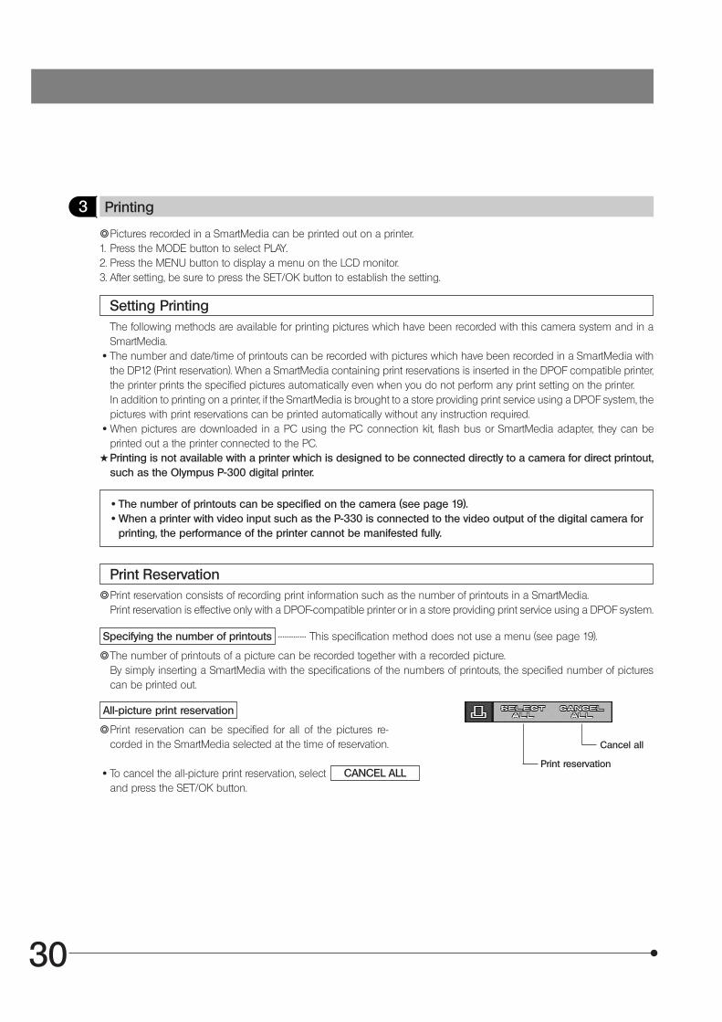
All-picture print reservation
}Print reservation can be specified for all of the pictures re-corded in the SmartMedia selected at the time of reservation.
· To cancel the all-picture print reservation, selectand press the SET/OK button.
..................
CANCEL ALLPrint reservation
Cancel all
31
DP12
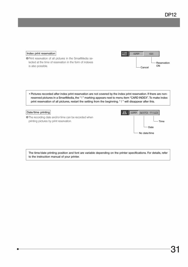
Index print reservation
}Print reservation of all pictures in the SmartMedia se-lected at the time of reservation in the form of indexesis also possible.
ReservationON
· Pictures recorded after index print reservation are not covered by the index print reservation. If there are non-reserved pictures in a SmartMedia, the “ ! ” marking appears next to menu item “CARD INDEX”. To make indexprint reservation of all pictures, restart the setting from the beginning. “ ! ” will disappear after this.
Date/time printing
}The recording date and/or time can be recorded whenprinting pictures by print reservation. Time
The time/date printing position and font are variable depending on the printer specifications. For details, referto the instruction manual of your printer.
Cancel
Date
No date/time

32
Fig. 22
Fig. 23
MONITOR DISPLAY OF PICTURES
}The recorded pictures can be displayed on a video monitor by using the provided video cable.This makes it possible to view the pictures on a large screen even when a PC is not available.Before connecting the cable, be sure to set the main switch of the control box to “ ” (OFF) and also turn off thevideo monitor.
1. Connect the video cable 1 to the video output connector 2 on thecontrol box.
2. Connect the other end 3 of the video cable to the video input connectorof the monitor.
1 Monitor Observation in Record Mode (Fig. 23)
1. Turn on the video monitor.2. Set the main switch of the control box to “ I ” (ON), then press the MODE
button 1 to select REC MANU or REC AUTO.3. The video monitor shows the live image.}Even if “Up/down inverted display" is set at “Setting the Picture Display
Orientation" (page 25), the image displayed is an erect image. Thencharacters in the scale displayed are inverted (Up/down inverted) im-ages.
2 Monitor Observation in Play Mode (Fig. 23)
1. Turn on the video monitor.2. Set the main switch of the control box to “ I ” (ON), then press the MODE
button 1 to select PLAY.3. The video monitor shows a playback picture.4. Press either MOVE button or 2 to select the picture to be displayed.
Use either MOVE button or 3 to select the magnification (1/16X to4X).
· The picture may not be displayed on the center of the screendepending on the adjustment of the monitor. This is not a mal-function.
· The displayed picture may be enclosed in a black frame de-pending on the video monitor in use. If the picture is output fromthe video monitor to a video printer, the black frame may benoticeable in the printout.
²
³@
²
³ @
33
DP12
The recorded pictures can be downloaded in a PC using optional image processing software.In this chapter, the method for connecting the DP12 to a PC and that for downloading images into the PC using the CD-ROM provided with the DP12-BSW PC connection kit.
1 Connecting a PC
}When the DP12 is connected to a PC using the optional DP12-BSW PC connection kit, the picture data can be down-loaded directly from the SmartMedia installed in the DP12 to the PC. The connection method is variable depending onthe PC model in use.
PC operation environment
Before connecting the DP12 to your PC, check that your PC matches the following condition (which assumes the use ofthe DP12-BSW PC connection kit).
{Use a IBM PC/AT compatible model.Operating system: Windows 98SE/2000/MeCPU: Pentium 150 MHz or moreHDD free space: 50 MB or moreMemory: 64 MB RAMConnector: USB interfaceMonitor: Minimum 256 colors, 800 x 600 dots or more (32000 colors or more recommended)
PC connection
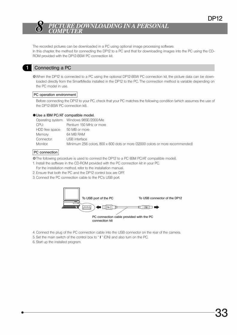
}The following procedure is used to connect the DP12 to a PC (IBM PC/AT compatible model).1. Install the software in the CD-ROM provided with the PC connection kit in your PC.
For the installation method, refer to the installation manual.2. Ensure that both the PC and the DP12 control box are OFF.3. Connect the PC connection cable to the PC’s USB port.
To USB port of the PC
4. Connect the plug of the PC connection cable into the USB connector on the rear of the camera.5. Set the main switch of the control box to “ I ” (ON) and also turn on the PC.6. Start up the installed program.
PICTURE DOWNLOADING IN A PERSONALCOMPUTER
PC connection cable provided with the PCconnection kit
To USB connector of the DP12
34
2 Loading Pictures
{Loading using the software in CD-ROMTo download recorded pictures to the PC through a USB cable for displaying them on or saving them in the PC, install thesoftware in the CD-ROM provided with the optional DP12-BSW in your PC.The following functions are available with the software in the CD-ROM. For installation and operation, refer to the on-linemanual of the software.
Communication with cameraPicture files in the camera system can be downloaded to the PC through a USB cable.
Image viewerPictures downloaded from the camera system or picture files stored in a disk can be displayed either as index display orsingle-picture display. Picture management is easy thanks to the hierarchical folder display like the Windows Explorer andthe drag & drop capability.
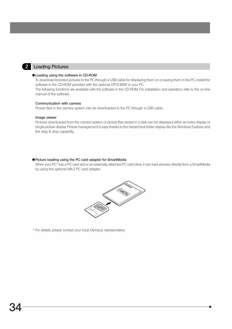
{Picture loading using the PC card adapter for SmartMediaWhen your PC* has a PC card slot or an externally attached PC card drive, it can load pictures directly from a SmartMediaby using the optional MA-2 PC card adapter.
* For details, please contact your local Olympus representative.
35
DP12
3 Playing Pictures on a PC
}To view recorded pictures on a PC screen, use the software in the CD-ROM provided with the optional DP12-BSW PCconnection kit.
{Playback of pictures recorded in a SmartMedia}Pictures recorded in the SmartMedia installed in the camera system can be viewed using the DP12-BSW.
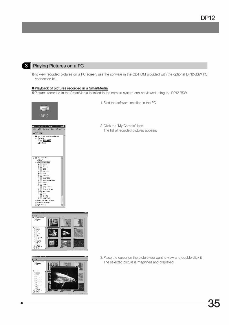
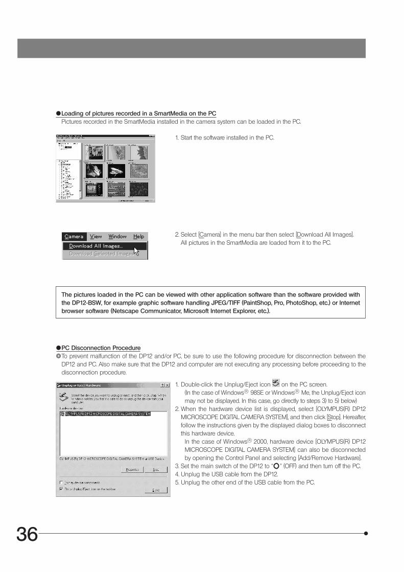
1. Start the software installed in the PC.
2. Click the “My Camera” icon.The list of recorded pictures appears.
3. Place the cursor on the picture you want to view and double-click it.The selected picture is magnified and displayed.
36
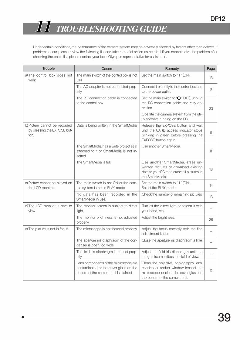
1. Double-click the Unplug/Eject icon on the PC screen.(In the case of Windows R 98SE or Windows R Me, the Unplug/Eject iconmay not be displayed. In this case, go directly to steps 3) to 5) below)
2. When the hardware device list is displayed, select [OLYMPUS(R) DP12MICROSCOPE DIGITAL CAMERA SYSTEM], and then click [Stop]. Hereafter,follow the instructions given by the displayed dialog boxes to disconnectthis hardware device.
In the case of Windows R 2000, hardware device [OLYMPUS(R) DP12MICROSCOPE DIGITAL CAMERA SYSTEM] can also be disconnectedby opening the Control Panel and selecting [Add/Remove Hardware].
3. Set the main switch of the DP12 to “ ” (OFF) and then turn off the PC.4. Unplug the USB cable from the DP12.5. Unplug the other end of the USB cable from the PC.
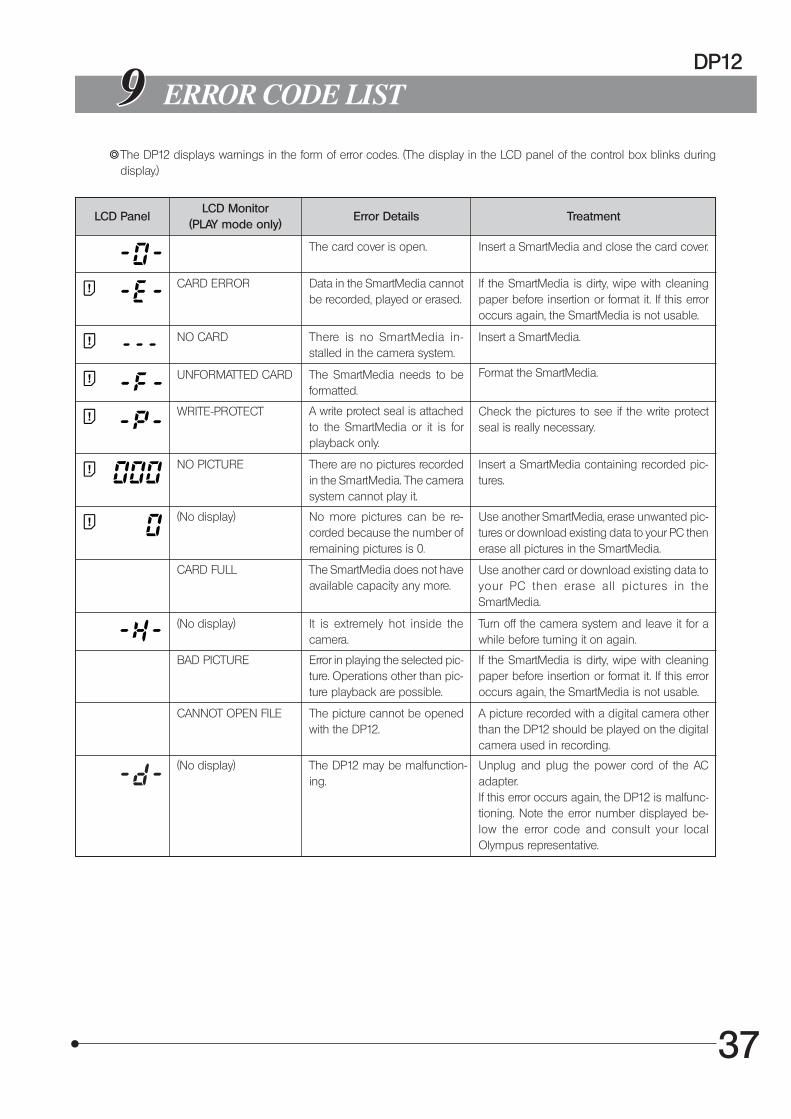
{Loading of pictures recorded in a SmartMedia on the PCPictures recorded in the SmartMedia installed in the camera system can be loaded in the PC.
1. Start the software installed in the PC.
2. Select [Camera] in the menu bar then select [Download All Images].All pictures in the SmartMedia are loaded from it to the PC.
The pictures loaded in the PC can be viewed with other application software than the software provided withthe DP12-BSW, for example graphic software handling JPEG/TIFF (PaintShop, Pro, PhotoShop, etc.) or Internetbrowser software (Netscape Communicator, Microsoft Internet Explorer, etc.).
{PC Disconnection Procedure}To prevent malfunction of the DP12 and/or PC, be sure to use the following procedure for disconnection between the
DP12 and PC. Also make sure that the DP12 and computer are not executing any processing before proceeding to thedisconnection procedure.
37
DP12
ERROR CODE LIST
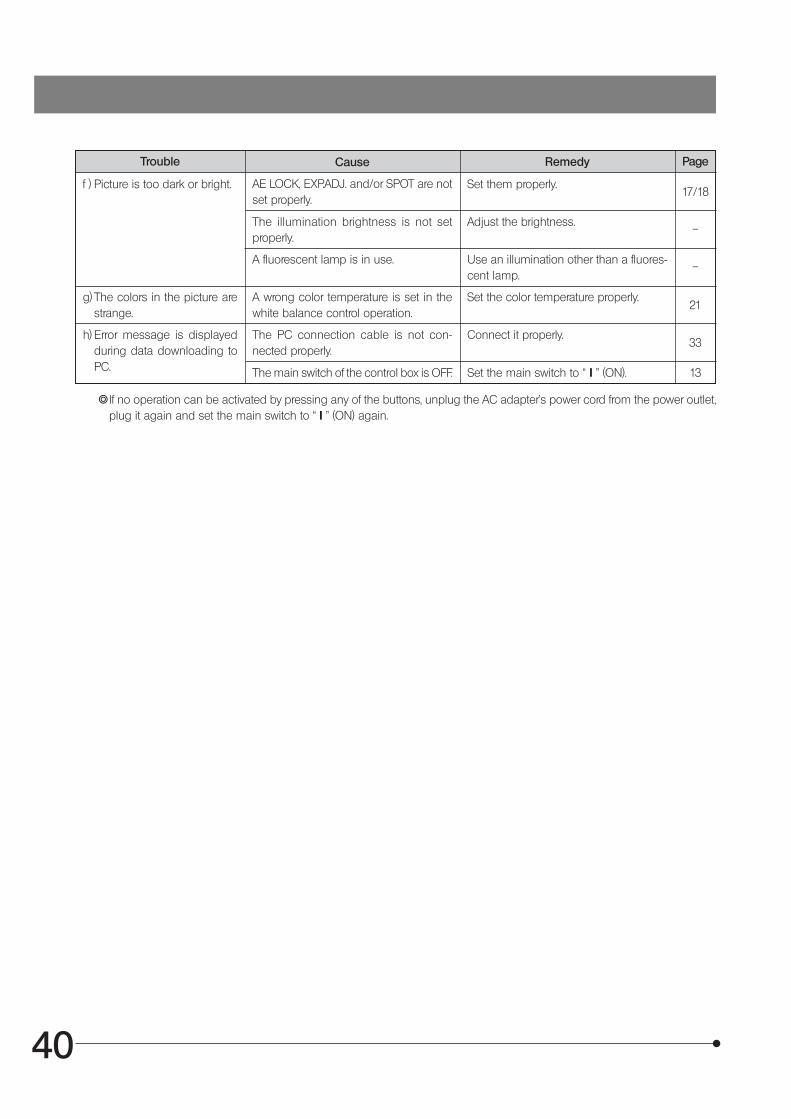
}The DP12 displays warnings in the form of error codes. (The display in the LCD panel of the control box blinks duringdisplay.)
LCD PanelLCD Monitor
(PLAY mode only)Error Details Treatment
The card cover is open. Insert a SmartMedia and close the card cover.
CARD ERROR Data in the SmartMedia cannotbe recorded, played or erased.
If the SmartMedia is dirty, wipe with cleaningpaper before insertion or format it. If this erroroccurs again, the SmartMedia is not usable.
NO CARD There is no SmartMedia in-stalled in the camera system.
Insert a SmartMedia.
UNFORMATTED CARD The SmartMedia needs to beformatted.
Format the SmartMedia.
WRITE-PROTECT A write protect seal is attachedto the SmartMedia or it is forplayback only.
Check the pictures to see if the write protectseal is really necessary.
NO PICTURE There are no pictures recordedin the SmartMedia. The camerasystem cannot play it.
Insert a SmartMedia containing recorded pic-tures.
(No display) No more pictures can be re-corded because the number ofremaining pictures is 0.
Use another SmartMedia, erase unwanted pic-tures or download existing data to your PC thenerase all pictures in the SmartMedia.
CARD FULL The SmartMedia does not haveavailable capacity any more.
Use another card or download existing data toyour PC then erase all pictures in theSmartMedia.
(No display) It is extremely hot inside thecamera.
Turn off the camera system and leave it for awhile before turning it on again.
BAD PICTURE Error in playing the selected pic-ture. Operations other than pic-ture playback are possible.
If the SmartMedia is dirty, wipe with cleaningpaper before insertion or format it. If this erroroccurs again, the SmartMedia is not usable.
CANNOT OPEN FILE The picture cannot be openedwith the DP12.
A picture recorded with a digital camera otherthan the DP12 should be played on the digitalcamera used in recording.
(No display) The DP12 may be malfunction-ing.
Unplug and plug the power cord of the ACadapter.If this error occurs again, the DP12 is malfunc-tioning. Note the error number displayed be-low the error code and consult your localOlympus representative.

38
SPECIFICATIONS
Item Specification
Type C-mount CCD camera unit & control box
Image pickup device 1/1.8-inch, 3.34 million pixels (3.24 million pixels effective).RGB primary color on-chip filters.Effective pixels: 2088(H) x 1550(V) pixels
CCD camera Sensitivity: ISO 25/50/100 equivalent.Photometry methods: Center-weighted average method (30% in center), spot metering
method (1% in center).Exposure control: AUTO, MANUAL, AE LOCK.Exposure time: AUTO (1/2 to 1/4000 sec. [exposure compensation ±2 EV])
MANUAL (8 to 1/4000 sec.)White balance control: Full auto, once-touch, manual (color temperature selection from
3000K, 3700K, 4000K, 4500K, 5500K and 6500K).
Image recording Image recording medium: 3.3 V SmartMedia (SSFDC) with 32 MB capacity.(16, 64 and 128 MB cards can also be used).
Recording formats: Digital recording, JPEG, DCF (Design rule for Camera File system),TIFF (non-compressed). DPOF compatible.
Recording pixels: 2048 x 1536 pixels in SHQ/HQ modes, 1024 x 768 or 640 x 480 pixelsin SQ mode.
LCD monitor* 3.5-inch TFT color LCD (approx. 200,000 pixels).
External interfaces PC connection: USB connector (type B).Video output: RCA pin jack.
Power supply Supply voltage: 6 V DC ±10%.Supply current: 2.5 A.
Dimensions/weight Camera unit: 119(W) x 110(D) x 53(H) mm, approx. 440 grams.Control box: 131(W) x 165(D) x 177(H) mm, approx. 690 grams.
Operating environment · Indoor use. · Altitude: Max. 2000 m · Ambient temperature: 5° to 40°C (41° to 104°F) · Maximum relative humidity: 80% for temperatures up to 31°C (88°F), decreasing lin-
early through 70% at 34°C (93°F), 60% at 37°C (99°F), to 50% relative humidity at 40°C(104°F).
· Supply voltage fluctuations; Not to exceed ±10% of the normal voltage. · Pollution degree: 2 (in accordance with IEC60664) · Installation/Overvoltage category: II (in accordance with IEC60664)
* Depending on the combination of the microscope and TV adapter in use, the directions of observation images may notcorrespond each other in the eyepiece and on the LCD monitor. Should this be the case, switch the picture display orientationto up/down inverted display (P. 25).
39
DP12
TROUBLESHOOTING GUIDE
Under certain conditions, the performance of the camera system may be adversely affected by factors other than defects. Ifproblems occur, please review the following list and take remedial action as needed. If you cannot solve the problem afterchecking the entire list, please contact your local Olympus representative for assistance.
Trouble Cause Remedy Page
a) The control box does notwork.
The main switch of the control box is notON.
Set the main switch to “ I ” (ON).13
The AC adapter is not connected prop-erly.
Connect it properly to the control box andto the power outlet.
9
The PC connection cable is connectedto the control box.
Set the main switch to “ ” (OFF), unplugthe PC connection cable and retry op-eration.
Operate the camera system from the util-ity software running on the PC.
33
b) Picture cannot be recordedby pressing the EXPOSE but-ton.
Data is being written in the SmartMedia. Release the EXPOSE button and waituntil the CARD access indicator stopsblinking in green before pressing theEXPOSE button again.
11
The SmartMedia has a write protect sealattached to it or SmartMedia is not in-serted.
Use another SmartMedia.11
The SmartMedia is full. Use another SmartMedia, erase un-wanted pictures or download existingdata to your PC then erase all pictures inthe SmartMedia.
13
c) Picture cannot be played onthe LCD monitor.
The main switch is not ON or the cam-era system is not in PLAY mode.
Set the main switch to “ I ” (ON).Select the PLAY mode.
14
No data has been recorded in theSmartMedia in use.
Check the number of remaining pictures.13
d) The LCD monitor is hard toview.
The monitor screen is subject to directlight.
Turn off the direct light or screen it withyour hand, etc.
–
The monitor brightness is not adjustedproperly.
Adjust the brightness.28
e) The picture is not in focus. The microscope is not focused properly. Adjust the focus correctly with the fineadjustment knob.
–
The aperture iris diaphragm of the con-denser is open too wide.
Close the aperture iris diaphragm a little.–
The field iris diaphragm is not set prop-erly.
Adjust the field iris diaphragm until theimage circumscribes the field of view.
–
Lens components of the microscope arecontaminated or the cover glass on thebottom of the camera unit is stained.
Clean the objective, photography lens,condenser and/or window lens of themicroscope, or clean the cover glass onthe bottom of the camera unit.
2
40
Trouble Cause Remedy Page
f ) Picture is too dark or bright. AE LOCK, EXP.ADJ. and/or SPOT are notset properly.
Set them properly.17/18
The illumination brightness is not setproperly.
Adjust the brightness.–
A fluorescent lamp is in use. Use an illumination other than a fluores-cent lamp.
–
g) The colors in the picture arestrange.
A wrong color temperature is set in thewhite balance control operation.
Set the color temperature properly.21
h) Error message is displayedduring data downloading toPC.
The PC connection cable is not con-nected properly.
Connect it properly.33
The main switch of the control box is OFF. Set the main switch to “ I ” (ON). 13
}If no operation can be activated by pressing any of the buttons, unplug the AC adapter’s power cord from the power outlet,plug it again and set the main switch to “ I ” (ON) again.
41
DP12
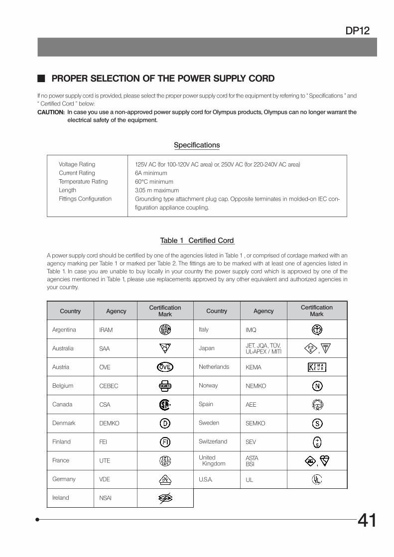
PROPER SELECTION OF THE POWER SUPPLY CORD
If no power supply cord is provided, please select the proper power supply cord for the equipment by referring to “ Specifications ” and“ Certified Cord ” below:CAUTION: In case you use a non-approved power supply cord for Olympus products, Olympus can no longer warrant the
electrical safety of the equipment.
Specifications
Voltage RatingCurrent RatingTemperature RatingLengthFittings Configuration
125V AC (for 100-120V AC area) or, 250V AC (for 220-240V AC area)6A minimum60°C minimum3.05 m maximumGrounding type attachment plug cap. Opposite terminates in molded-on IEC con-figuration appliance coupling.
Table 1 Certified Cord
A power supply cord should be certified by one of the agencies listed in Table 1 , or comprised of cordage marked with anagency marking per Table 1 or marked per Table 2. The fittings are to be marked with at least one of agencies listed inTable 1. In case you are unable to buy locally in your country the power supply cord which is approved by one of theagencies mentioned in Table 1, please use replacements approved by any other equivalent and authorized agencies inyour country.
Country Agency CertificationMark Country Agency
CertificationMark
Argentina
Australia
Austria
Belgium
Canada
Denmark
Finland
France
Germany
Ireland
IRAM
SAA
ÖVE
CEBEC
CSA
DEMKO
FEI
UTE
VDE
NSAI
Italy
Japan
Netherlands
Norway
Spain
Sweden
Switzerland
United Kingdom
U.S.A.
IMQ
KEMA
NEMKO
AEE
SEMKO
SEV
ASTABSI
UL
JET, JQA , TÜV,UL-APEX / MITI
42
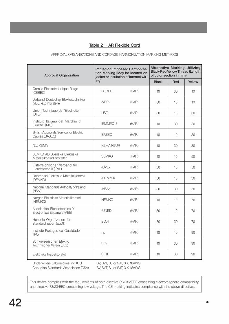
Table 2 HAR Flexible Cord
APPROVAL ORGANIZATIONS AND CORDAGE HARMONIZATION MARKING METHODS
Approval Organization
Printed or Embossed Harmoniza-tion Marking (May be located onjacket or insulation of internal wir-ing)
Alternative Marking UtilizingBlack-Red-Yellow Thread (Lengthof color section in mm)
Black Red Yellow
Comite Electrotechnique Belge(CEBEC)
Verband Deutscher Elektrotechniker(VDE) e.V. Prüfstelle
Union Technique de l´Electricite´(UTE)
Instituto Italiano del Marchio diQualita´ (IMQ)
British Approvals Service for ElectricCables (BASEC)
N.V. KEMA
SEMKO AB Svenska ElektriskaMaterielkontrollanstalter
Österreichischer Verband fürElektrotechnik (ÖVE)
Danmarks Elektriske Materialkontroll(DEMKO)
National Standards Authority of Ireland(NSAI)
Norges Elektriske Materiellkontroll(NEMKO)
Asociacion Electrotecnica YElectronica Espanola (AEE)
Hellenic Organization forStandardization (ELOT)
Instituto Portages da Qualidade(IPQ)
Schweizerischer ElektroTechnischer Verein (SEV)
Elektriska Inspektoratet
CEBEC <HAR>
<VDE> <HAR>
USE <HAR>
IEMMEQU <HAR>
BASEC <HAR>
KEMA-KEUR <HAR>
SEMKO <HAR>
<ÖVE> <HAR>
<DEMKO> <HAR>
<NSAI> <HAR>
NEMKO <HAR>
<UNED> <HAR>
ELOT <HAR>
np <HAR>
SEV <HAR>
SETI <HAR>
10 30 10
30 10 10
30 10 30
10 30 50
10 10 30
10 30 30
10 10 50
30 10 50
30 10 30
30 30 50
10 10 70
30 10 70
30 30 70
10 10 90
10 30 90
10 30 90
Underwriters Laboratories Inc. (UL) SV, SVT, SJ or SJT, 3 X 18AWGCanadian Standards Association (CSA) SV, SVT, SJ or SJT, 3 X 18AWG
This device complies with the requirements of both directive 89/336/EEC concerning electromagnetic compatibilityand directive 73/23/EEC concerning low voltage. The CE marking indicates compliance with the above directives.

This publication is printed on recycled paper.
Printed in Japan 2003 02 M 000–²
2-43-2,Hatagaya, Shibuya-ku, Tokyo, Japan
Postfach 10 49 08, 20034, Hamburg, Germany
2 Corporate Center Drive, Melville, NY 11747-3157, U.S.A.
491B River Valley Road, #12-01/04 Valley Point Office Tower, Singapore 248373
2-8 Honduras Street, London EC1Y OTX, United Kingdom.
104 Ferntree Gully Road, Oakleigh, Victoria, 3166, Australia
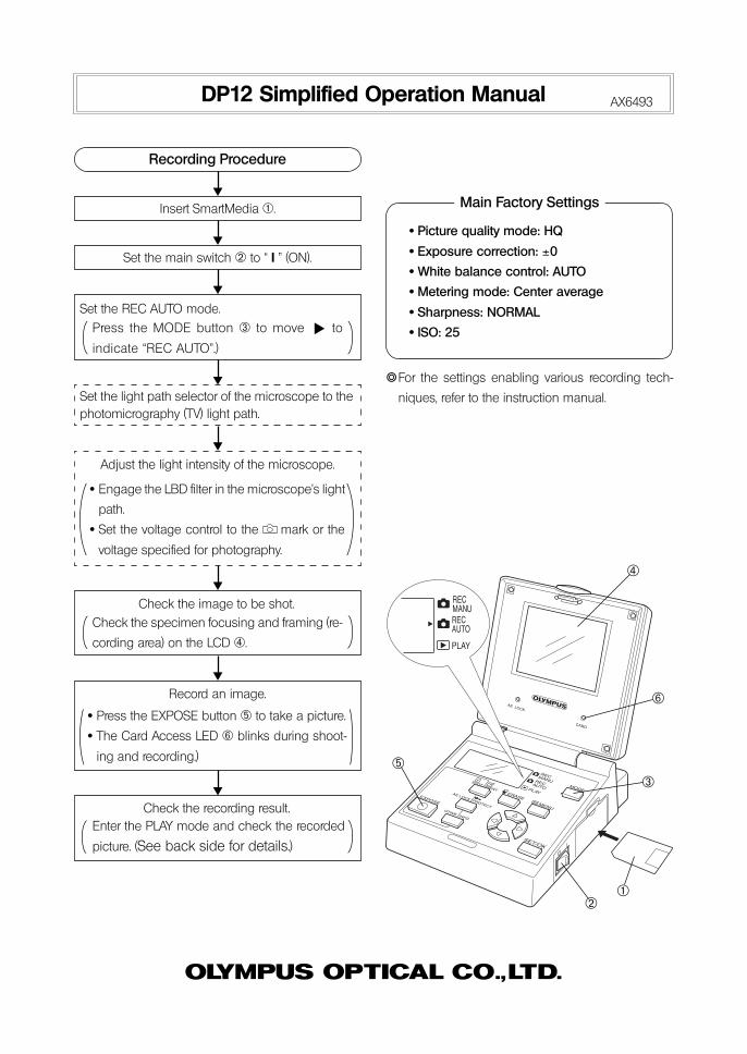
Set the REC AUTO mode.
Press the MODE button ³ to move to
indicate “REC AUTO”.)
DP12 Simplified Operation Manual AX6493
Recording Procedure
Insert SmartMedia @.
Set the main switch ² to “ I ” (ON).
Set the light path selector of the microscope to thephotomicrography (TV) light path.
· Engage the LBD filter in the microscope’s light
path.
· Set the voltage control to the mark or the
voltage specified for photography.
Adjust the light intensity of the microscope.
Check the image to be shot.Check the specimen focusing and framing (re-
cording area) on the LCD |.
Record an image.
· Press the EXPOSE button ƒ to take a picture.
· The Card Access LED … blinks during shoot-
ing and recording.)
Check the recording result.Enter the PLAY mode and check the recorded
picture. (See back side for details.)
· Picture quality mode: HQ
· Exposure correction: ±0
· White balance control: AUTO
· Metering mode: Center average
· Sharpness: NORMAL
· ISO: 25
}For the settings enabling various recording tech-
niques, refer to the instruction manual.
Main Factory Settings
@²
³
|
ƒ
…

Shinjuku Monolith, 3-1, Nishi Shinjuku 2-chome, Shinjuku-ku, Tokyo, Japan
Postfach 10 49 08, 20034, Hamburg, Germany
2 Corporate Center Drive, Melville, NY 11747-3157, U.S.A.
One Corporate Drive, Orangeburg, NY 10962, U.S.A.
491B River Valley Road, #12-01/04 Valley Point Office Tower, Singapore 248373
2-8 Honduras Street, London EC1Y OTX, United Kingdom.
31 Gilby Road, Mt. Waverley, VIC 3149, Melbourne, Australia.
6100 Blue Lagoon Drive, Suite 390 Miami, FL 33126-2087, U.S.A.
Printed in Japan 2005 05 M 020–³
This publication is printed on recycled paper.

![Quantifiers, Unit Symbols, Chemical Symbols and Symbols of … · 2019-02-26 · [Technical Data] Quantifiers, Unit Symbols, Chemical Symbols and Symbols of Elements Excerpts from](https://img.dokumen.tips/doc/110x75/5ea0ef282df5855ac23d36fb/quantifiers-unit-symbols-chemical-symbols-and-symbols-of-2019-02-26-technical.jpg)


![Quantifiers, Unit Symbols, Chemical Symbols and Symbols ...[Technical Data] Quantifiers, Unit Symbols, Chemical Symbols and Symbols of Elements Excerpts from JIS Z 8202 Calculation](https://img.dokumen.tips/doc/110x75/613ff166b44ffa75b8048971/quantifiers-unit-symbols-chemical-symbols-and-symbols-technical-data-quantifiers.jpg)