GERB TOA radiances and fluxes validation over the Valencia AnchoGERB TOA radiances and fluxes validation over the Valencia Anchor Station r Station
during the IV GERB Ground Validation Campaignduring the IV GERB Ground Validation CampaignA. Velázquez Blázquez1, A. Cano1, N. Clerbaux2, S. Dewitte2, C. Doménech1, V. Estellés3, A.G. Ferreira1, L. Gonzalez2, J. Jorge Sanchez4, C. Narbón1, D. Pino4,6, A. Rius6, G. L.
Smith5,7, Z. P. Szewczyk5,8, R. Tarruella4, J. Torrobella6, E. Lopez-Baeza1
(1) Climatology from Satellites Group, Dept. of Physics of the Earth and Thermodynamics, University of Valencia, Spain, (2) Royal Meteorological Institute of Belgium (RMIB), Belgium, (3) Solar Radiation Group, Dept. of Physics of the Earth and Thermodynamics, University of
Valencia, Spain ,
(4) Polytechnic University of Catalonia, Spain, (5) NASA Langley Research Center (LaRC),VA, USA, (6) Institute of Space Studies of Catalonia, Spain, (7) National Institute for Aerospace, Hampton, VA, USA,
(8)Science Applications International Corporation, Hampton, VA, USA
4th ESA EO Summer School on Earth System Monitoring and Modelling.
ESRIN, Frascatti, 4 – 14 August 2008
ABSTRACTABSTRACTThe Geostationary Earth Radiation Budget (GERB) instrument on boThe Geostationary Earth Radiation Budget (GERB) instrument on board Meteosatard Meteosat--8 and 8 and --9 provides accurate measurements of shortwave and longwave broad9 provides accurate measurements of shortwave and longwave broadband radiances and fluxes at the Top band radiances and fluxes at the Top
Of the Atmosphere (TOA) with very high temporal resolution of 15Of the Atmosphere (TOA) with very high temporal resolution of 15 minutes.minutes.
The aim of this study is to validate radiances and fluxes at theThe aim of this study is to validate radiances and fluxes at the TOA measured by GERB during the IV GERB Ground Validation CampaTOA measured by GERB during the IV GERB Ground Validation Campaign at the Valencia Anchor Station (VAS) area (31ign at the Valencia Anchor Station (VAS) area (31stst July July –– 66thth August August
2006). In the study, GERB enhanced spatial resolution data (GERB2006). In the study, GERB enhanced spatial resolution data (GERB High Resolution) is used, where the resolution of the computed High Resolution) is used, where the resolution of the computed fluxes is improved through the combination of wellfluxes is improved through the combination of well--calibrated GERB calibrated GERB
broadband data with SEVIRI narrowbroadband data with SEVIRI narrow--band highband high--samplingsampling--rate data. Clouds and the Earthrate data. Clouds and the Earth’’s Radiant Energy System (CERES) Terra FM2 data is also used froms Radiant Energy System (CERES) Terra FM2 data is also used from dedicated PAPS (Programmable Azimuth dedicated PAPS (Programmable Azimuth
Plane Scanning) observations over the study area during FebruarPlane Scanning) observations over the study area during February 2004 campaign.y 2004 campaign.
The validation capabilities of the Valencia Anchor Station have The validation capabilities of the Valencia Anchor Station have previously been assessed by successfully reproducing CERES TOA rpreviously been assessed by successfully reproducing CERES TOA radiances and fluxes with the occasion of different ground validaadiances and fluxes with the occasion of different ground validation tion
campaigns. The methodology consists in performing radiative trancampaigns. The methodology consists in performing radiative transfer simulations of CERES and GERB TOA radiances and fluxes fromsfer simulations of CERES and GERB TOA radiances and fluxes from independent ground measurements of surface and atmospheric independent ground measurements of surface and atmospheric
parameters (such as derived precipitable water parameters (such as derived precipitable water vapourvapour content from CIMEL sunphotometer and GPS (Global Positioning Sycontent from CIMEL sunphotometer and GPS (Global Positioning System) instruments, radiosoundings from the Spanish stations of Mstem) instruments, radiosoundings from the Spanish stations of Madrid and adrid and
Murcia, aerosol optical thickness also from CIMEL, broadband albMurcia, aerosol optical thickness also from CIMEL, broadband albedo and temperature over shrubs, bare soil and vineyards in the edo and temperature over shrubs, bare soil and vineyards in the study area) in conjunction with other satellite products such asstudy area) in conjunction with other satellite products such as TOMS TOMS
(Total Ozone Mapping Spectrometer) ozone, CERES/SARB emissivity (Total Ozone Mapping Spectrometer) ozone, CERES/SARB emissivity and MODIS BRDF (Bidirectional Reflectance Distribution Function)and MODIS BRDF (Bidirectional Reflectance Distribution Function). The latter allows us to analyze the contribution of each land . The latter allows us to analyze the contribution of each land use use
to the anisotropy of the shortwave radiation field and constitutto the anisotropy of the shortwave radiation field and constitutes a good improvement of the methodology that had been tested foes a good improvement of the methodology that had been tested for the case of CERES in previous campaigns. The comparison betweer the case of CERES in previous campaigns. The comparison between n
simulations and CERES calibrated and validated data provides a gsimulations and CERES calibrated and validated data provides a good indicator of the reliability of the methodology to be applieood indicator of the reliability of the methodology to be applied as a validation tool for GERB.d as a validation tool for GERB.
THE VAS SITETHE VAS SITE
LANDSAT 5LANDSAT 5
5TH JULY 2003 5TH JULY 2003
(RGB)(RGB)
ACKNOWLEDGMENTSACKNOWLEDGMENTSWe would like to thank the Spanish Institute for Meteorology for their
collaboration on the radiosounding ascents and the Institute for
Space Studies of Catalonia for their collaborations with the GPS
measurements.
The authors wish to thank the CERES Science Team for their
support and provision of the data.
ToTo reproduce reproduce radiancesradiances andand fluxesfluxes at at thethe TOA, TOA, itit isis neededneeded a a goodgood
characterizationcharacterization ofof thethe surfacesurface andand thethe atmosphereatmosphere..
AtmosphericAtmospheric profilesprofiles
•• Water Water VapourVapour:: Radiosounding ascents interpolated to 1m resolution and Radiosounding ascents interpolated to 1m resolution and
completed with MLW (completed with MLW (Mid Latitude WinterMid Latitude Winter) profiles. Then, select 94) profiles. Then, select 94--95 levels 95 levels
and scale the profile to the integrated water vapor retrieval oband scale the profile to the integrated water vapor retrieval obtained with the tained with the
GPS (GPS (Global Positioning SystemGlobal Positioning System))
•• Ozone:Ozone: MLW profile scaled to TOMS (MLW profile scaled to TOMS (Total Ozone Mapping SpectrometerTotal Ozone Mapping Spectrometer) )
valuesvalues
•• Aerosols:Aerosols: STREAMER MLW standard profile, assuming background STREAMER MLW standard profile, assuming background
tropospheric aerosols and background stratospheric aerosols and tropospheric aerosols and background stratospheric aerosols and aerosol aerosol
optical thickness from CIMEL photometer measurementsoptical thickness from CIMEL photometer measurements
SeSelection of surface parameterslection of surface parameters
MethodologyMethodology
••Surface EmissivitySurface EmissivitySurface EmissivitySurface EmissivitySurface EmissivitySurface EmissivitySurface EmissivitySurface Emissivity from CERES/SARB (from CERES/SARB (from CERES/SARB (from CERES/SARB (from CERES/SARB (from CERES/SARB (from CERES/SARB (from CERES/SARB (Surface and Atmospheric Radiation BudgetSurface and Atmospheric Radiation BudgetSurface and Atmospheric Radiation BudgetSurface and Atmospheric Radiation BudgetSurface and Atmospheric Radiation BudgetSurface and Atmospheric Radiation BudgetSurface and Atmospheric Radiation BudgetSurface and Atmospheric Radiation Budget), Wilber et al, 1999), Wilber et al, 1999), Wilber et al, 1999), Wilber et al, 1999), Wilber et al, 1999), Wilber et al, 1999), Wilber et al, 1999), Wilber et al, 1999
••Surface TemperatureSurface TemperatureSurface TemperatureSurface TemperatureSurface TemperatureSurface TemperatureSurface TemperatureSurface Temperature from from from from from from from from Valencia Anchor StationValencia Anchor StationValencia Anchor StationValencia Anchor StationValencia Anchor StationValencia Anchor StationValencia Anchor StationValencia Anchor Station and mobile station (land use classification weighted)and mobile station (land use classification weighted)and mobile station (land use classification weighted)and mobile station (land use classification weighted)and mobile station (land use classification weighted)and mobile station (land use classification weighted)and mobile station (land use classification weighted)and mobile station (land use classification weighted)
BRDF = k0 + k1 * fross-thick + k2 * fli-sparse
GERB OBSERVATIONSGERB OBSERVATIONS CERES PAPS observations over VASCERES PAPS observations over VAS
Sample of CERES FM2 TOA Shortwave
Radiances over the VAS. 1st August 2006, 10z.
Sample of CERES FM2 TOA Shortwave
Radiances over the VAS. 1st August 2006, 11z.
Sample of CERES FM3 TOA Shortwave Radiances
over the VAS. 12th February 2004, 13z.
•• BRDF:BRDF: calculated from the isometric, volumetric and geometric calculated from the isometric, volumetric and geometric
Kernels of the MOD43B1 product for the RossKernels of the MOD43B1 product for the Ross--ThickThick--LiLi--SparseSparse--
Reciprocal model.Reciprocal model.
Parameters from MODIS/Terra 1km resolution, SIN Grid, 1Parameters from MODIS/Terra 1km resolution, SIN Grid, 1Parameters from MODIS/Terra 1km resolution, SIN Grid, 1Parameters from MODIS/Terra 1km resolution, SIN Grid, 1----16 day16 day16 day16 day
RMSE_SW = 4.8 W m-2 sr-1
RMSE_LW = 1.3 W m-2 sr-1
RMSE_SW = 4.1 W m-2 sr-1
RMSE_LW = 2.1 W m-2 sr-1
RMSE_SW = 14.9 W m-2
RMSE_LW = 2.7 W m-2
RMSE_SW = 8.6 W m-2
RMSE_LW = 7.8 W m-2
CERES simulationsCERES simulations
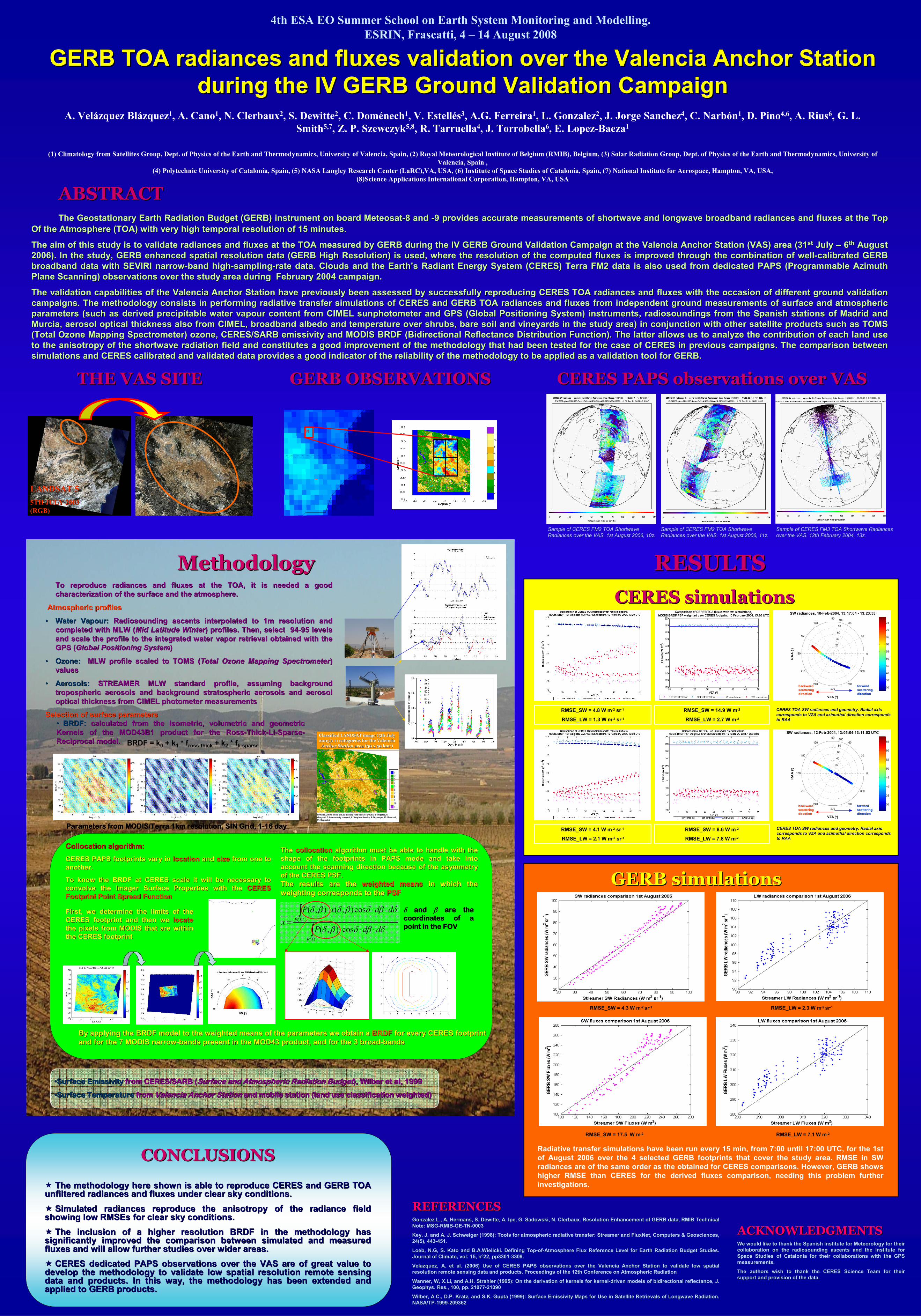
RMSE_SW = 4.3 W m-2 sr-1 RMSE_LW = 2.3 W m-2 sr-1
RMSE_SW = 17.5 W m-2 RMSE_LW = 7.1 W m-2
GERB simulationsGERB simulations
CONCLUSIONSCONCLUSIONS
� The methodology here shown is able to reproduce CERES and GERB TThe methodology here shown is able to reproduce CERES and GERB TOA OA unfiltered radiances and fluxes under clear sky conditions. unfiltered radiances and fluxes under clear sky conditions.
�� Simulated radiances reproduce the anisotropy of the radiance fiSimulated radiances reproduce the anisotropy of the radiance field eld showing low showing low RMSEsRMSEs for clear sky conditions. for clear sky conditions.
�� The inclusion of a higher resolution BRDF in the methodology haThe inclusion of a higher resolution BRDF in the methodology has s significantly improved the comparison between simulated and meassignificantly improved the comparison between simulated and measured ured fluxes and will allow further studies over wider areas.fluxes and will allow further studies over wider areas.
�� CERES dedicated PAPS observations over the VAS are of great valCERES dedicated PAPS observations over the VAS are of great value to ue to develop the methodology to validate low spatial resolution remotdevelop the methodology to validate low spatial resolution remote sensing e sensing data and products. In this way, the methodology has been extendedata and products. In this way, the methodology has been extended and d and applied to GERB products. applied to GERB products.
ClassifiedClassified LANDSAT LANDSAT imageimage (5th (5th JulyJuly
2003): 11 2003): 11 categoriescategories forfor thethe Valencia Valencia
Anchor StationAnchor Station areaarea (50 x 50 km(50 x 50 km22))
1: Water, 2:Pine trees, 3: Low-density Pine trees,4: Shrubs, 5: Irrigated, 6:
Vineyard, 7: Low-density vineyard, 8: Very low density, 9: Dry crops, 10: Bare soil,
11: Degraded
REFERENCESREFERENCESGonzalez L., A. Hermans, S. Dewitte, A. Ipe, G. Sadowski, N. Clerbaux. Resolution Enhancement of GERB data, RMIB Technical
Note: MSG-RMIB-GE-TN-0003
Key, J. and A. J. Schweiger (1998): Tools for atmospheric radiative transfer: Streamer and FluxNet, Computers & Geosciences,
24(5), 443-451.
Loeb, N.G, S. Kato and B.A.Wielicki. Defining Top-of-Atmosphere Flux Reference Level for Earth Radiation Budget Studies.
Journal of Climate, vol: 15, nº22, pp3301-3309.
Velazquez, A. et al. (2006) Use of CERES PAPS observations over the Valencia Anchor Station to validate low spatial
resolution remote sensing data and products. Proceedings of the 12th Conference on Atmospheric Radiation
Wanner, W, X.Li, and A.H. Strahler (1995): On the derivation of kernels for kernel-driven models of bidirectional reflectance, J.
Geophys. Res., 100, pp. 21077-21090
Wilber, A.C., D.P. Kratz, and S.K. Gupta (1999): Surface Emissivity Maps for Use in Satellite Retrievals of Longwave Radiation.
NASA/TP-1999-209362
RESULTSRESULTS
CollocationCollocation algorithmalgorithm::
CERES PAPS footprints vary in CERES PAPS footprints vary in locationlocation and and sizesize from one to from one to
another.another.
To know the BRDF at CERES scale it will be necessary to To know the BRDF at CERES scale it will be necessary to
convolve the Imager Surface Properties with the convolve the Imager Surface Properties with the CERES CERES
Footprint Point Spread FunctionFootprint Point Spread Function
δδδδ and and and and ββββ are the are the are the are the
coordinates of a coordinates of a coordinates of a coordinates of a
point in the FOVpoint in the FOVpoint in the FOVpoint in the FOVδβδβδ
δβδβδβδ
ddP
ddxP
x
FOV
FOV
⋅⋅⋅
⋅⋅⋅
=∫
∫cos),(
cos),(),(
The The collocationcollocation algorithm must be able to handle with the algorithm must be able to handle with the
shape of the footprints in PAPS mode and take into shape of the footprints in PAPS mode and take into
account the scanning direction because of the asymmetry account the scanning direction because of the asymmetry
of the CERES PSF.of the CERES PSF.
The results are the The results are the weighted meansweighted means in which the in which the
weighting corresponds to the weighting corresponds to the PSFPSF
By applying the BRDF model to the weighted means of the parameteBy applying the BRDF model to the weighted means of the parameters we obtain a rs we obtain a BRDFBRDF for every CERES footprint for every CERES footprint
and for the 7 MODIS narrowand for the 7 MODIS narrow--bands present in the MOD43 product, and for the 3 broadbands present in the MOD43 product, and for the 3 broad--bandsbands
First, we determine the limits of the First, we determine the limits of the
CERES footprint and then we CERES footprint and then we locatelocate
the pixels from MODIS that are within the pixels from MODIS that are within
the CERES footprintthe CERES footprint
20
40
60
80
100
30
210
60
240
90
270
120
300
150
330
180 0
SW radiances, 12-Feb-2004, 13:05:04-13:11:53 UTC
VZA (°°°°)
RAA ( °° °°)
30
35
40
45
50
55
60
65
forward
scattering
direction
backward
scattering
direction
CERES TOA SW radiances and geometry. Radial axis CERES TOA SW radiances and geometry. Radial axis
corresponds to VZA and corresponds to VZA and azimuthalazimuthal direction corresponds direction corresponds
to RAAto RAA
20
40
60
80
100
30
210
60
240
90
270
120
300
150
330
180 0
SW radiances, 10-Feb-2004, 13:17:04 - 13:23:53
VZA (°°°°)
RAA ( °° °°)
30
35
40
45
50
55
60
65
70
75
forward
scattering
direction
backward
scattering
direction
CERES TOA SW radiances and geometry. Radial axis CERES TOA SW radiances and geometry. Radial axis
corresponds to VZA and corresponds to VZA and azimuthalazimuthal direction corresponds direction corresponds
to RAAto RAA
Radiative transfer simulations have been run every 15 min, from 7:00 until 17:00 UTC, for the 1st
of August 2006 over the 4 selected GERB footprints that cover the study area. RMSE in SW
radiances are of the same order as the obtained for CERES comparisons. However, GERB shows
higher RMSE than CERES for the derived fluxes comparison, needing this problem further
investigations.
Recommended