Pallavi et al. World Journal of Engineering Research and Technology
www.wjert.org
256
EXPERIMENTAL AND CFD ANALYSIS OF JET IMPINGEMENT
COOLING ON COPPER CIRCULAR PLATE
Pallavi C. Chaudhari*1, Ashish N. Sarode
2 and Rajesh V. Dahibhate
3
1ME Thermal Engineering student in G. H. Raisoni Institute of Engineering and
Management, Jalgaon.
2Asst. Professor in Mechanical Engineering department, G.H. Raisoni Institute of
Engineering and Management, Jalgaon.
3 HOD of Mechanical engineering department in G.H.Raisoni Institute of Engineering and
Management, Jalgaon
Article Received on 17/06/2017 Article Revised on 07/07/2017 Article Accepted on 28/07/2017
ABSTRACT
This study presents the Experimental and Computational Fluid
Dynamics (CFD) analysis on Jet impingement cooling. Jet
impingement is highly effective convective heat transfer technology
and improving heat transfer enhancement in various applications. The
fluid flow and heat transfer characteristics of jet impinging on circular
copper plate is investigated by experimentally and CFD analysis were done. This study on jet
impingement cooling is conducted to optimize the parameters like 6 mm and 8 mm nozzle
diameters, Distance between jet to target spacing have taken 10 cm (h/d) and the velocity of
the jet (3 LPM,5 LPM,8 LPM). Experiment has conducted with water as coolants
.Experimental data is recorded as per requirement and results are validated by using CFD
simulation, it gives the rapid cooling rate. This study shows the result about Reynolds number
increases with decreasing temperature and Nusselt number increases as the flow rate for
different nozzle diameters increases. Form this analysis, obtained optimum cooling range
with 6 mm and 8 mm diameters when h/d consider 10 cm with various flow rates. The results
shows maximum Reynold no. is at 6 mm nozzle diameter and maximum Nusselt no. is as 8
mm nozzle diameter. There is good results agreement in between experimentation and CFD
simulation.
wjert, 2017, Vol. 3, Issue 5, 256-267.
World Journal of Engineering Research and Technology
WJERT
www.wjert.org
ISSN 2454-695X Original Article
SJIF Impact Factor: 4.326
*Corresponding Author
Pallavi C. Chaudhari
ME Thermal Engineering
student in G.H.Raisoni
Institute of Engineering and
Management, Jalgaon.

Pallavi et al. World Journal of Engineering Research and Technology
www.wjert.org
257
KEYWORDS: Jet Impingement; CFD simulation; Heat Transfer; Cooling range; Reynolds
Number; Nusselt number.
INTRODUCTION
New development in engineering industry has always brought about challenging tasks. To
fulfill the needs of industries requirement with best result in minimum time span is very
important. So in this paper introduce new topic for to enhance the heat transfer rate with the
help of jet impingement. It is a time consuming process and provide immediate cooling to
product.
It is necessary not only to maintain low temperature of components but also avoid hot spot.
Now a day Jet impingement heat transfer is extensively used for cooling electronic
components, cooling critical machinery structures, annealing metal plates, and numerous
industrial processes and also include turbine blade cooling paper and fabric drying , furnace
heating, tempering of glass and metal sheets, electronic chip cooling, food processing and
many others. Jet impingement cooling is one of the most efficient solutions of cooling hot
objects in industrial processes as it produces a very high heat transfer rate through forced
convection. Since the heat transfer rate is very high at the area where the jet directly impinges
on it provides rapid cooling or heating on the local heat transfer area. Many researches study
on the varying nozzle diameters and specimen structures. Most of the works are available on
flat plate.
Figure 1: Jet Impingement.
Dushyant singh et. al[1]
this study focuses the parameter like nozzle diameter, distance
between nozzle exit, h/d and the circular cylinder and ratio of nozzle diameter to the diameter

Pallavi et al. World Journal of Engineering Research and Technology
www.wjert.org
258
of the heated target cylinder d/D. It was observed that the stagnation Nusselt number
increases monotonically as the h/d decreases and the effects of h/d and d/D are significant
only in the jet impinging region. Based on the experimental results, a correlation for the
stagnation Nusselt number has also been developed.
Kyo sung Choo et. al[2]
study on the influence of nozzle diameter on the circular hydraulic
jump of liquid jet impingement, it investigate the effect of nozzle diameter
(0.381,0.506,1,2,3.9,6.7,8mm) on hydraulic jump radius. So the result show that hydraulic
jump radius is independent of the nozzle diameter under fixed impingement power
conditions, while the hydraulic jump radius increases with decreasing nozzle diameter under
fixed jet Reynolds number condition.
M. Johson et al.[3]
Many studies are available on smooth surfaces but investigated the jet
impingement on micro scale patterned surfaces exhibiting ribs and cavities tested in both
wetted cavity regions called hydrophilic and unwetted cavity regions called super
hydrophobic.
Qiang Guo et. al[4]
This study consist of 6mm inner diameter and Reynold number varied
from 14,000 to 53,000 with nozzle exit to the target plate is varied from 4 to 8.it gives the
result the local nusselt number rapidly increases when the air jet began its impingement.
Islam et al.[5]
experimented on the transient heat transfer of a target surface under a hot air
impinging jet. They placed thermocouples on the target surface to determine the temperature
and found that the heat flux at stagnation was maximum. Moreover, the heat flux was
maximum at the non-dimensional distance between the nozzle exit and the target plate H/Dn
= 2 and thereafter decreased as H/Dn increased.
E. Baydar et al[6]
study investigate the effects of Reynold number and nozzle to plate spacing
on the flow structure are examined. It consist of spacing range 0.2 to 6 and Reynold numbers
ranging from 30,000 to 50,000. A sub atmospheric region occurs on the impingement plate at
nozzle-to-plate spacing up to 2 for Reynolds numbers studied and it moves radically outward
from the stagnation point with increasing nozzle-to-plate spacing. It is concluded that there
exists a linkage among the sub atmospheric region, turbulence intensity and heat transfer
coefficients. The numerical results obtained using the standard k–e turbulence model are in
agreement with the experimental results except for the nozzle-to-plate spacing less than one.

Pallavi et al. World Journal of Engineering Research and Technology
www.wjert.org
259
V. Jeevanlal et. al[7]
the present work investigates the parameter like nozzle exit to target
plate distance and jet velocity. For the experiment consist of stainless steel plate with 10mm
nozzle diameter. It gives the result nusselt number increases with increasing Z/D value upto a
certain Z/D value then it starts decreasing.
Kumagai et al.[8]
conducted an experimental study on transient heat transfer of a sub cooling
water jet impinging on a hot metal plate. They found that an excessive time is necessary for
the evaporation of sufficient vapor to form a finite vapor layer because the water jet was sub
cooled, thereby resulting in a rapid decrease of the temperature at stagnation.
Rahman et al.[9]
conducted a numerical investigation on the transient heat transfer of a free
liquid jet impinging on a hemispherical plate. The study was performed for Re of 500–1500,
dimensionless plate thickness to nozzle diameter ratio ranging from 0.083 to 1.5, and three
solid materials (copper, silicon, and constantan). The results indicated that an increasing Re
number and plate thickness reduced the time it takes for the plate to reach the steady-state
condition. A higher Nusselt number was obtained with a lower thermal conductivity material.
Experimentation
Figure 2: Experimental set up.
A schematic diagram of the experimental apparatus for impinging water jets is shown in
Figure 2. The water jet vertically impinges on copper plates. The water flow was supplied by
a water tank to ensure a steady flow. A Rotameter flowmeter (1 to 30 LPM) was used to
measure liquid flow rates. The jet velocity can be readily found from the mass flow rate and
the jet diameter. The circular pipe nozzle was fixed on a 3 axis (x–y–z) stage. Thus, the
nozzle could be moved either parallel or perpendicular to the direction of the jet. Two
Pallavi et al. World Journal of Engineering Research and Technology
www.wjert.org
260
circular, brass nozzles were used in the experiment. The nozzles had diameters of 6 and 8
mm. All of the nozzles in the experiment are straight tubes and to ensure a fully developed
flow. The impingement surface was elevated above the remainder of the test section. Thus, as
the wall jets fell off the impingement surface into the pool, the jet impingement was not
influenced by the downstream conditions. The impingement plates were made of Copper and
here used two shapes of plates. The distance between nozzle diameters to target surface had
taken 10cm. The water temperature at the nozzle exit was fixed at 320C. K-type thermocouple
was used for measuring different point temperatures on plates. First Copper plate heated at
2470C then place in water collecting tank on glass plate. Glass plate provided for insulation
purpose after words jet impinges on heated plate and note down the readings.
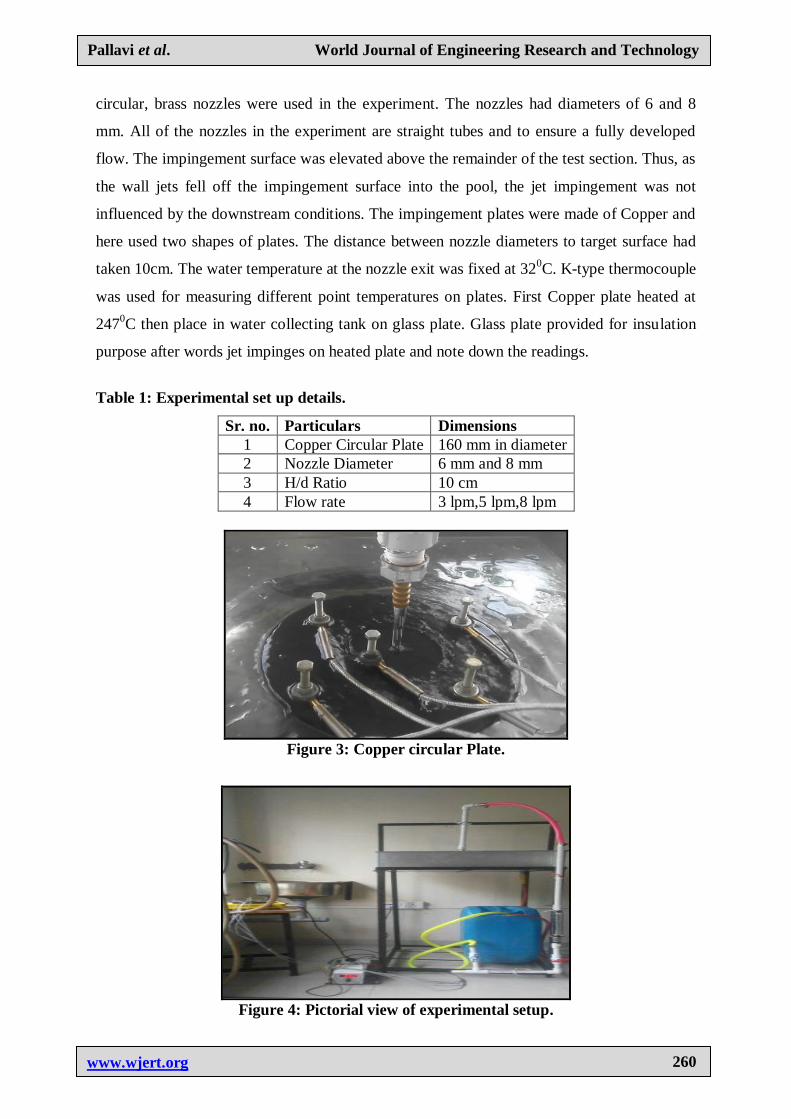
Table 1: Experimental set up details.
Sr. no. Particulars Dimensions
1 Copper Circular Plate 160 mm in diameter
2 Nozzle Diameter 6 mm and 8 mm
3 H/d Ratio 10 cm
4 Flow rate 3 lpm,5 lpm,8 lpm
Figure 3: Copper circular Plate.
Figure 4: Pictorial view of experimental setup.

Pallavi et al. World Journal of Engineering Research and Technology
www.wjert.org
261
Reynolds’s Number
Where, , kg/m3;V = Velocity of jet, m/s;d = Diameter of nozzle, m;
µ = Dynamic viscosity, N.s/m2;
Nusselt Number
Where, h= convective heat transfer coefficient, W/m2 -
0C; d= diameter of nozzle, m;
k= Thermal Conductivity of water, W/m-K;
(10)
Where, Nuavg = average Nusselt number; Re = Reynold’s number; Pr = Prandtl number;
l/d = nozzle to surface distance to nozzle diameter ratio.
Cfd Simulation
The 3D model for Copper circular plate is created using CATIA software. It is imported for
CFD simulation workbench with .igs/step file saved in CATIA. The geometrical specification
of Copper circular plate is as per design. Consider specification for circular plate 160 mm
diameters and 3 mm thickness.
Figure 5: Model of Circular plate.
Grid generation for circular copper plate
More accurate results could be obtained when more suitable grid and step sizes are used in
the numerical calculation. In this study, grid generation of nozzle flow and circular plate was
prime importance for gives better simulation results which is obtained discrete cell into which
the domain is divided. All the fixed parameters were solved at centers of these discrete cells.
Pallavi et al. World Journal of Engineering Research and Technology
www.wjert.org
262
So the accurate mesh generally provides better results at the increased computational time.
Therefore the size of the mesh in the domain should be gradually increased to such level that
the further raise in the number of control volumes does not result in considerable changes in
experimental results produced.
Figure 6: Mesh generation of nozzle flow and circular copper plate.
Boundary Conditions
Boundary conditions are used according to the need of the model. Boundary conditions used
at inlets and outlet for nozzle flow velocity and temperature of water and at outlet at static
pressure is applied. Domain surface is used as a wall with ‘No Slip Condition’.
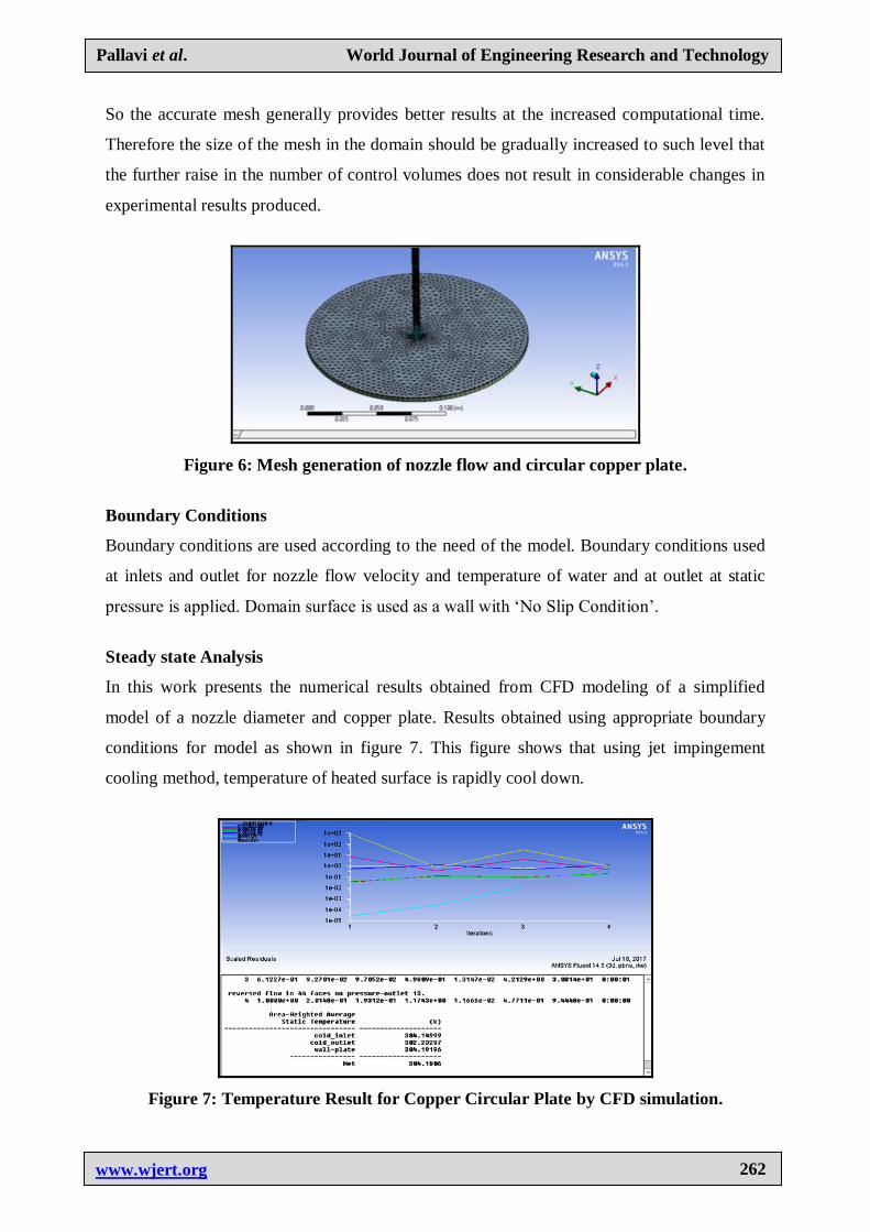
Steady state Analysis
In this work presents the numerical results obtained from CFD modeling of a simplified
model of a nozzle diameter and copper plate. Results obtained using appropriate boundary
conditions for model as shown in figure 7. This figure shows that using jet impingement
cooling method, temperature of heated surface is rapidly cool down.
Figure 7: Temperature Result for Copper Circular Plate by CFD simulation.
Pallavi et al. World Journal of Engineering Research and Technology
www.wjert.org
263
Effect of jet impingement on heated plates
When water jet impinged on copper plates with different nozzle diameters, flow rates, the
heated plates rapidly settle down. Figure 8 shows that temperature difference on whole plate
surface at different point temperature in different colors.
Figure 8: Effect of Jet impingement on heated circular copper plate.
RESULTS AND DISCUSSIONS
This study was investigated for rapid cooling to heated component. So work performed on
some essential parameters which play an important role in jet impingement cooling like
nozzle diameters(6 mm,8 mm), Distance between nozzle exit to target plate, jet velocity(3
lpm,5 lpm,8 lpm) have taken. In this experiment circular copper plate consider and there
result given below with the help of graph.
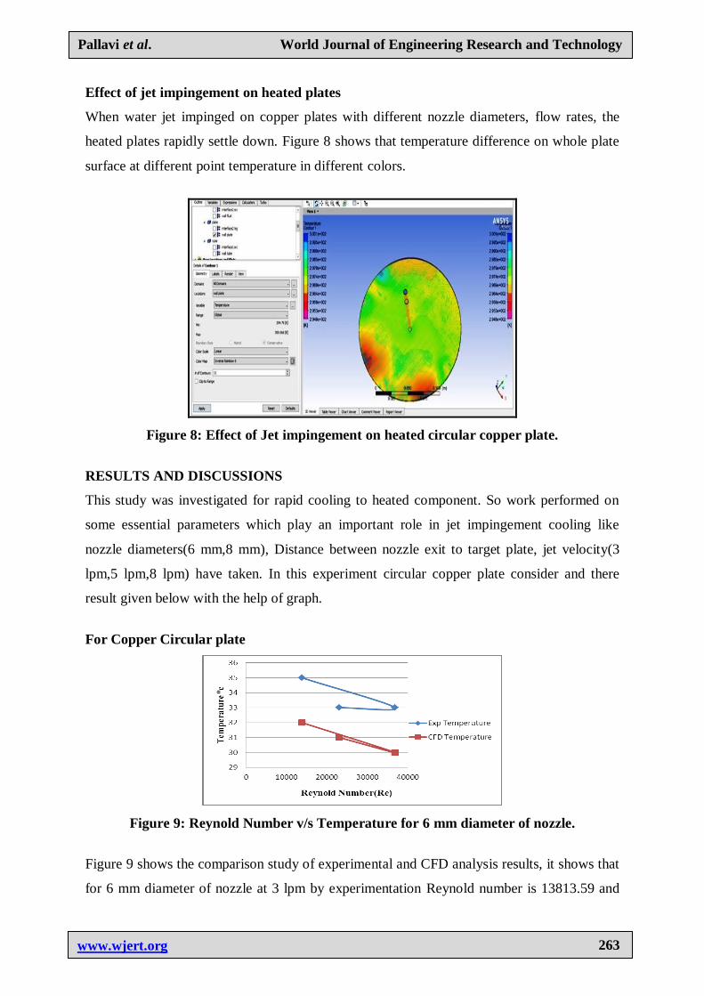
For Copper Circular plate
Figure 9: Reynold Number v/s Temperature for 6 mm diameter of nozzle.
Figure 9 shows the comparison study of experimental and CFD analysis results, it shows that
for 6 mm diameter of nozzle at 3 lpm by experimentation Reynold number is 13813.59 and

Pallavi et al. World Journal of Engineering Research and Technology
www.wjert.org
264
temperature is 350C, similarlly for 5 lpm and 8 lpm Reynold number and temperature is
23022.91, 36831.03 and 330C, 33
0C respectivily. By simulation at the same time and same
flow rate and same Reynold number it indicate temperature 320C, 31
0C and 30
0C
respectivily. And for 8 mm diameter of nozzle from figure 10 at 3 lpm, 5 lpm, 8 lpm by
experimentation Reynold number is 10358.76, 17255.92, 27617.8 and temperature is 350C,
340C, 33
0C. also at same at the same time and same flow rate and same Reynold number the
temperature range is 310C, 31
0C, 29
0C. So the concluded that Reynold number increases with
temperature decreases of circular copper plate.
Figure 10: Reynold Number v/s Temperature for 8mm diameter of nozzle.
Figure 11: Mass Flow Rate v/s Reynold Number.
When water jet impinged on heated Copper plate under considerable flow rates of 3,5 and 8
lpm, from figure 11 for 6 mm diameter of nozzle shows maximum Reynold number is
36831.03 observed at 8 lpm flow rate and also shows that for 8 mm diameter of nozzle for
same flow rate (8 lpm) maximum Reynold number is 27617.8 observed. So it gives final
judgement from above figure 11 6mm diameter of nozzle is more effective than 8mm diamter
of nozzle.
Pallavi et al. World Journal of Engineering Research and Technology
www.wjert.org
265
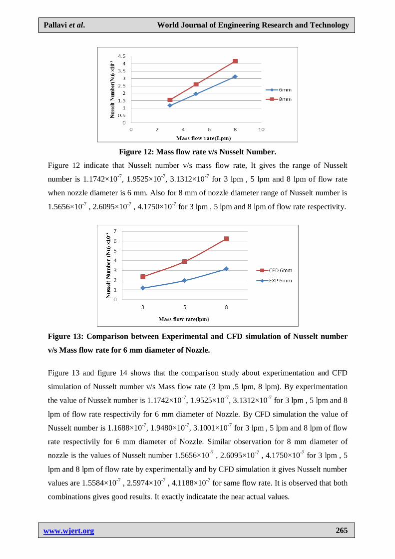
Figure 12: Mass flow rate v/s Nusselt Number.
Figure 12 indicate that Nusselt number v/s mass flow rate, It gives the range of Nusselt
number is 1.1742×10⁻⁷
, 1.9525×10⁻⁷
, 3.1312×10⁻⁷
for 3 lpm , 5 lpm and 8 lpm of flow rate
when nozzle diameter is 6 mm. Also for 8 mm of nozzle diameter range of Nusselt number is
1.5656×10⁻⁷
, 2.6095×10⁻⁷
, 4.1750×10⁻⁷
for 3 lpm , 5 lpm and 8 lpm of flow rate respectivity.
Figure 13: Comparison between Experimental and CFD simulation of Nusselt number
v/s Mass flow rate for 6 mm diameter of Nozzle.
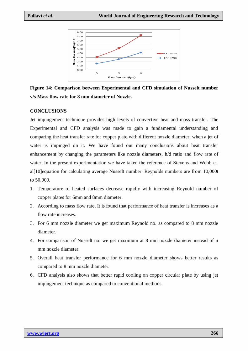
Figure 13 and figure 14 shows that the comparison study about experimentation and CFD
simulation of Nusselt number v/s Mass flow rate (3 lpm ,5 lpm, 8 lpm). By experimentation
the value of Nusselt number is 1.1742×10⁻⁷
, 1.9525×10⁻⁷
, 3.1312×10⁻⁷
for 3 lpm , 5 lpm and 8
lpm of flow rate respectivily for 6 mm diameter of Nozzle. By CFD simulation the value of
Nusselt number is 1.1688×10⁻⁷
, 1.9480×10⁻⁷
, 3.1001×10⁻⁷
for 3 lpm , 5 lpm and 8 lpm of flow
rate respectivily for 6 mm diameter of Nozzle. Similar observation for 8 mm diameter of
nozzle is the values of Nusselt number 1.5656×10⁻⁷
, 2.6095×10⁻⁷
, 4.1750×10⁻⁷
for 3 lpm , 5
lpm and 8 lpm of flow rate by experimentally and by CFD simulation it gives Nusselt number
values are 1.5584×10⁻⁷
, 2.5974×10⁻⁷
, 4.1188×10⁻⁷
for same flow rate. It is observed that both
combinations gives good results. It exactly indicatate the near actual values.
Pallavi et al. World Journal of Engineering Research and Technology
www.wjert.org
266
Figure 14: Comparison between Experimental and CFD simulation of Nusselt number
v/s Mass flow rate for 8 mm diameter of Nozzle.
CONCLUSIONS
Jet impingement technique provides high levels of convective heat and mass transfer. The
Experimental and CFD analysis was made to gain a fundamental understanding and
comparing the heat transfer rate for copper plate with different nozzle diameter, when a jet of
water is impinged on it. We have found out many conclusions about heat transfer
enhancement by changing the parameters like nozzle diameters, h/d ratio and flow rate of
water. In the present experimentation we have taken the reference of Stevens and Webb et.
al[10]equation for calculating average Nusselt number. Reynolds numbers are from 10,000t
to 50,000.
1. Temperature of heated surfaces decrease rapidly with increasing Reynold number of
copper plates for 6mm and 8mm diameter.
2. According to mass flow rate, It is found that performance of heat transfer is increases as a
flow rate increases.
3. For 6 mm nozzle diameter we get maximum Reynold no. as compared to 8 mm nozzle
diameter.
4. For comparison of Nusselt no. we get maximum at 8 mm nozzle diameter instead of 6
mm nozzle diameter.
5. Overall heat transfer performance for 6 mm nozzle diameter shows better results as
compared to 8 mm nozzle diameter.
6. CFD analysis also shows that better rapid cooling on copper circular plate by using jet
impingement technique as compared to conventional methods.

Pallavi et al. World Journal of Engineering Research and Technology
www.wjert.org
267
REFERENCES
1. Dushyant Singh, B. Premachandran, Sangeeta Kohli. ‘Circular air jet impingement
cooling of a circular cylinder with flow confinement’, International Journal of Heat and
Mass Transfer, 2015; 969–989.
2. Kyo Sung Choo, Sung Jin Kim, ‘Heat transfer characteristics of impingement air jets
under a fixed pumping power condition, Int. Journal of heat and mass transfer, 2009; 305-
701.
3. M. Johnson, D. Maynes, J. Crockett, ‘Experimental Characterization of Hydraulic Jump
Caused By Jet Impingement on Micro-Patterned Surfaces Exhibiting Ribs And Cavities’,
Exp. Thermal and fluid Sci, 2014; 216-223.
4. Qiang Guo, Zhi Wen, Ruifeng Dou, ‘Experimental and numerical study on the transient
heat-transfer characteristics of circular air-jet impingement on a flat plate’,International
Journal of Heat and Mass Transfer, 2017; 1177–1188.
5. A.K.M.N. Islam, M.A. Islam, M. Saha, Experimental investigation of transient heat
transfer on a solid surface, with fire retardant fabric under hot air impinging jet, Proc.
Eng., 2015 105: 167–175.
6. E. Baydar, Y. Ozmen, ‘An Experimental And Numerical Investigation on a Confined
Impinging Air Jet at High Reynolds Numbers’ Applied thermal Engg, 2005; 409-421.
7. V. M. Jeevanlal, B. C. Anil Kumar, ‘Experimental investigation on heat transfer from a
flat and surface indented plate impinged with cold air jet using circular nozzle’, IJEERT,
2014.
8. S. Kumagai, S. Suzuki, R. Kubo, et al., Transient cooling of a hot metal plate with an
impinging water jet, Heat Transfer Jpn. Res., 1995; 24(6).
9. M.M. Rahman, C.F. Hernandez, Transient conjugate heat transfer from a hemispherical
plate during free liquid jet impingement on the convex surface, Heat Mass Transfer,
2011; 47(1): 69–80.
10. J. Stevens and B.W. Webb, Local heat transfer coefficients under an axisymmetric, single
phase liquid jet. ASME Journal of Heat Transfer, 1991; 113(572): 71-72.
Recommended