Course 7
Control of wind turbines

Control Concepts • Wind turbines must provide reliable operation in all
operating states. • As well as appropriate dimensioning of the turbine,
drive train and tower, the control and management systems, which are described in the next section, are of particular importance.
• For this reason, it is necessary to develop a local, turbine-specific profile of requirements, to expand this into a strategy that takes into account the desires of operators, manufacturers, power supply companies, etc., and to translate this into a control plan.
• This can be used for the dimensioning of the regulator, the simulation of the turbine and the design of the control mechanisms from a hardware point of view.

Control in isolated operation• Figure 7.1 shows the control diagram for a wind
turbine fitted with a synchronous generator in isolated operation.
• A power regulator influences the power to be drawn from the wind by varying the blade pitch, allowing output to be held almost constant if the wind speed is sufficiently high.
• By limiting regulator output, this power control circuit can control a speed regulator.
• Controlled running-up and shut-down processes are thus achieved in the same manner as speed constancy within a tolerance range predetermined by the regulator and adjustment system.


• For reasons of stability with regard to turbine characteristics and for the reduction of component loading, it is advisable, particularly for larger turbines, to add a blade pitch and/or blade pitch adjustment speed regulation circuit (internal cascade) and a blade pitch adjustment acceleration regulation circuit to the speed or output control circuit.
• The output voltage can be adjusted within narrow limits by using a separate voltage regulator if the generator excitation can be externally controlled. This regulation circuit is often integrated into the generator system. Voltage can thus be regulated to constant values or (as is usually the case) altered in accordance with the characteristic in Figure 7.2 with the aid of a reactive power drooping characteristic and matched to the reactive power conditions. A low inductive load leads to the predetermined desired value for the open-circuit grid voltage UNdes. Highly inductive consumers, on the other hand, bring about voltage reductions.
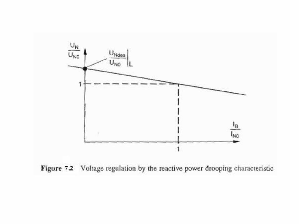

An adjustment of voltage can take place such that the actual value of the grid voltage UNact arises synthetically from the grid voltage UN by reactive power correction. Alternatively, voltage regulation with a reactive power-dependent desired value is possible (Figure 7.3 ). The grid voltage desired value UNdes is made up of the no-load desired value of grid voltage UNdesL .


It is possible in a similar way to correct the turbine rotational speed or the grid frequency with the aid of an active power drooping characteristic according to the load state, as shown in the characteristic in Figure 7.4 , in such a way that low loads lead to slightly increased rotation speeds and frequency values (e.g. 52 Hz at no-load). These fall to 48 Hz at high loads, for example, when operating at nominal ratings. Thus the actual values as well as the desired values (Figure 7.5) can be corrected, depending upon the load.


The structure shown in Figure 7.1 can also be used for the regulation of the blade pitch, output and speed of a wind turbine with an asynchronous generator in isolated operation. The voltage regulation shown in Figure 7.6 (b) can take place within a large fluctuation range using capacitors that can be connected in stages, as shown in Figure 7.6 (a). The voltage change can be reduced with an increasing number of capacitor stages. In practice n = 2 to 5 stages are used. Larger variation ranges, e.g. with 12 stages, are the exception. Voltage and frequency can also be kept within narrow limits using rapid switching systems (fig.7.6 c,d).The capacitors provide the excitation reactive power for the induction machine. The additional resistor Rz permits also the control of the stator frequency within narrow limits by slip variation.


For small wind turbines, sensing the blade pitch is relatively costly. To avoid this, the inclusion of pitch position and pitch speed regulation circuits can be dispensed (fig. 7.7).The speed or power control circuit thus acts directly upon the blade pitch adjustment mechanism and regulates the blade pitch angle according to the prevailing speed and output values, without knowing the actual value of the angle.


Regulation of variable-speed turbines
Control structures for variable-speed turbines can easily be derived from the concepts developed for the control of wind turbines in separate operation.
Instead of a fixed speed, or a speed predetermined by the power drooping characteristic, as shown in Figure 7.1, the speed producing the optimum output is determined and the turbine is run as close to this speed as possible. This type of system must therefore be designed with two different types of speed control circuit (Figure 7.8).

• The regulation circuit in the upper section of the diagram has the task of limiting the input power and speed of the turbine at full-load operation to the nominal value, e.g. by adjusting the blade pitch.
• The second speed control circuit in the lower section of the diagram on the other hand, must control the turbine speed by controlling the generator electric torque such that the turbine output takes on optimal values or achieves a reliable operating state and behaviour that protects components from excess loading.

• Variable-speed turbines thus provide the option of reducing the load on drive-train components by rapid intervention. This can be achieved by targeted regulation or by limiting the generator torque and using the transient effects of all rotating masses in the drive train.
• The control structure as shown in Figure 7.8 is therefore suitable for both grid and isolated operation.
• The prerequisite for isolated operation is, however, that a self-commutated and self-clocked inverteris used that is capable of forming a grid and covering the active and reactive power.

Regulation of variable-slip asynchronous generators
• Asynchronous machines permit operation in the oversynchronous and undersynchronous range, i.e. above and below the synchronous speed.
• The speed of asynchronous machines can be varied if their generators have multiphase coils (m = 2, 3, ... ) and current transfer via slip rings. Speed can also be varied inductively, and thus without brushes, via additional coils, by:– up to around 10 % with dynamic slip control ,– approximately 30 % in oversynchronous operation
using power converter cascades – around 40 % in under-and oversynchronous
operation in double-fed systems.

Double-fed asynchronous generators • Asynchronous machines with slip-ring rotors
are generally designed with three-phase a.c. windings in the stator and rotor. Thus the windings in the stator and rotor can be supplied from three-phase systems of different frequency and voltage. Moreover, the magnetization (as in synchronous machines) can be wholly or partly supplied through either of the two electric circuits.
• The stator is normally connected directly with the supply grid. The rotor is then supplied via a frequency converter. Thus the angular velocity of the stator rotary field :

is equal to the sum of angular velocity of mechanical rotation wmcch and the rotor current frequency ω2 . Depending upon direction of the supply frequency, the machine can thus be operated in either the undersynchronous or oversynchronous mode. The pole numbers of the stator and rotor (p1 and p2 respectively) at the angular velocity of the rotary fields must be allowed for here.
• The rotor active power
is obtained from the product of the slip s and air-gap power Pδ . Thus the power that the rotor circuit transfers to or from the grid via a frequency converter is also proportional to slip. The slip-dependent speed-regulating range of the generator, e.g. 0.6 ≤ n/no≤ 1.4, therefore determines maximum output (and thus to a large extent the cost) of the required frequency converter.

The magnetizing current of asynchronous machines is made up of the sum of stator and rotor currents. This allows the machine speed and thus also the turbine speed to be varied. Figure 7.9 shows the structure for the regulation of a double-fed asynchronous generator and illustrates the complexity of such systems. The transformation of the active and reactive components of the total output of large machines into the two-axis coordinate system: with d as the direct-axis and q as the quadrature-axis component (Figure 7.9, top centre) leads, if we disregard stator resistance, to a complete disconnection between the active power, or the largely corresponding machine torque variable, and reactive power.Thus, the two state variables can be regulated separately without mutual interaction.


In order to make use of the advantages of variable-speed conversion systems, the total output of the machine PG should be influenced by the regulation system, and the generator and turbine speed should be dictated in a controlled manner. To control the rotational speed (upper-left part of the block diagram) the speed-output characteristic can be used. Speed is influenced by torque, as is normal for rotating systems. This can be adjusted by means of the quadrature-axis component of the rotor current iRq by suitable control of the machine frequency converter via the rotor voltage. The reactive power can be predetermined in a similar manner, e.g. as a fixed desired value, or can be guided according to the requirements of the power generation company by means of the direct-axis component of rotor current iRd with the aid of the machine frequency converter (Figure 7.9, bottom left). Instead of reactive power QTdes the power factor can be predetermined and thus adjusted.
• Thus the double-fed asynchronous generator can be adjusted or regulated via the pulse-controlled inverter on the machine side for the desired values of speed, torque and active power, as well as reactive power or the power factor.
• In order to avoid disruptive connections between the grid-side pulse-controlled inverter and the overall regulation system via the machine-side pulse-controlled jnverter, the grid frequency converters can be operated by the d.c. link voltage (see Figure 7.9, bottom right). This can be kept roughly constant by a preset hysteresis band. In this manner, the grid-side frequency converter adapts to the value and phase of the required active power and works within the preset tolerance band in neutral operation. The grid-side reactive power in the rotor can therefore be kept close to zero and the total reactive power can thus be adjusted by means of the reactive power regulation system at the machine frequency converter.

• High-speed current changes can occur in the stator circuit, particularly if the generator is suddenly disconnected from the grid for some reason, e.g. by the tripping of protective switches or by rapid auto-reclosure. These current changes induce high-voltage peaks in the rotor winding. To prevent this, overvoltage protection must be fitted in the rotor (see figure 7.9, centre).
• The doubly-fed asynchronous machine is particularly suitable for use as a generator in wind turbines. Due to the connection of the stator to the grid, these machines combine the beneficial electrical characteristics of synchronous machines with mechanical advantages associated with speed variability at very good efficiency.

They thus allow the mechanical loading of the drive train to be significantly lessened and the fluctuations of electrical output power to be greatly reduced. By the use of IGBT pulse-controlled inverters in the rotor circuit, grid reactions caused by harmonics can be reduced to a noncritical level. Other options for capacitive and inductive operation can be used for grid support. Thus wind turbines with double-fed asynchronous generators can, particularly in weak grids, give access to significant connection capacities.

Asynchronous generators with oversynchronous power converter cascades
• Compared with double-fed asynchronous generators, much simpler conversion systems are achieved if slip-ring rotor machines are only operated in the oversynchronous speed range.
• In this system, the slip power of the rotor can be drawn from the rotor and supplied to the three-phase grid via an uncontrolled or controlled rectifier and via a line-commutated or self commutated inverter (Scherbius principle). This type of converter system is characterized by its robust and low-maintenance construction and, moreover represents a very reasonably priced variant.
• Figure 7.10 shows the relatively simple structure for the control of the converter system.


• The machine-side rectifier converts the variable-frequency alternating variables of the rotor (voltage uR and current iR) into direct variables (ug, ig). The direct current of the d.c. link is inverted to grid frequency by an inverter and matched to the grid voltage by a transformer.
• This system therefore brings about a complete decoupling of rotor speed and grid frequency.
• Rectifiers and inverters can take the form of diode rectifiers or thyristor-controlled or pulse- controlled a.c. converters.
• Active power speed regulation is similar to that in a double-fed machine. However, the speed variations are limited to a much narrower range. Reactive power regulation is no simple matter. Overload protection, e.g. in the form of a switchable resistor, protects the d.c. link from overload and impedes uncontrolled operation of the generator.

• However, as is the case for cage rotor machines, the reactive power for the excitation of the generator must be provided by the grid or by an additional compensation unit . In an oversynchronous power converter cascade, the commutation reactive power of the rotor-side rectifier, the phase-control reactive power of the inverter and the distortion reactive power of the entire turbine must also be provided if, for example, thyristor valves are used.
• The phase-control reactive power of the inverter can be reduced to low values by specifying a narrow oversynchronous speed range. To achieve this, the inverter must be adjusted to the inverter stability limit when the generator is running at its maximum speed. Thus a reserve voltage must be dispensed with in order to fully utilize the d.c. link.
Recommended


![010 Cursul Nr[1]. 7 SA](https://img.dokumen.tips/doc/110x75/563db827550346aa9a91059d/010-cursul-nr1-7-sa.jpg)