CA08104001E For more information, visit: www.eaton.com/consultants
February 2017
Contents
Switching Devices —Low Voltage 28.0-1Sheet 28
22
23
24
25
26
27
28
29
30
31
32
33
34
35
36
37
38
39
40
41
42
43
001
Sw
itch
ing
Devic
es
—L
ow
Vo
lta
ge Switching Devices—Low Voltage
General Description . . . . . . . . . . . . . . . . . . . . . . . . . . . . . . . . . . . . . . . . . . 28.0-2
General-Duty. . . . . . . . . . . . . . . . . . . . . . . . . . . . . . . . . . . . . . . . . . . . . . . . 28.0-3
Heavy-Duty . . . . . . . . . . . . . . . . . . . . . . . . . . . . . . . . . . . . . . . . . . . . . . . . . 28.0-3
Enhanced Visible Blade . . . . . . . . . . . . . . . . . . . . . . . . . . . . . . . . . . . . . . . 28.0-3
EnviroLine . . . . . . . . . . . . . . . . . . . . . . . . . . . . . . . . . . . . . . . . . . . . . . . . . . 28.0-4
Shunt Trip Safety Switch . . . . . . . . . . . . . . . . . . . . . . . . . . . . . . . . . . . . . . 28.0-5
Six-Pole Motor Circuit . . . . . . . . . . . . . . . . . . . . . . . . . . . . . . . . . . . . . . . . 28.0-5
Heavy-Duty Double-Throw . . . . . . . . . . . . . . . . . . . . . . . . . . . . . . . . . . . . 28.0-6
Quick-Connect Switches . . . . . . . . . . . . . . . . . . . . . . . . . . . . . . . . . . . . . . 28.0-6
Elevator Control Switch . . . . . . . . . . . . . . . . . . . . . . . . . . . . . . . . . . . . . . . 28.0-7
OEM Line Isolation (OLI) Switch . . . . . . . . . . . . . . . . . . . . . . . . . . . . . . . . 28.0-10
NEMA 7/9—Hazardous Location Disconnect Switch . . . . . . . . . . . . . . . . . . . 28.0-11
Auxiliary Power Heavy-Duty Safety Switch . . . . . . . . . . . . . . . . . . . . . . . . . . . 28.0-11
Heavy-Duty—Solar Photovoltaic Switch Single-Circuit . . . . . . . . . . . . . . . 28.0-12
Heavy-Duty—Solar Photovoltaic Switch Multi-Circuit . . . . . . . . . . . . . . . . 28.0-12
Enclosed Rotary . . . . . . . . . . . . . . . . . . . . . . . . . . . . . . . . . . . . . . . . . . . . . 28.0-12
Flex Center Factory Modifications . . . . . . . . . . . . . . . . . . . . . . . . . . . . . . 28.0-13
Selection Guide . . . . . . . . . . . . . . . . . . . . . . . . . . . . . . . . . . . . . . . . . . . . . 28.0-14
Catalog Numbering System . . . . . . . . . . . . . . . . . . . . . . . . . . . . . . . . . . . 28.0-15
K-Series Switch Design Features . . . . . . . . . . . . . . . . . . . . . . . . . . . . . . . 28.0-18
Accessories, Hubs, Lug Data . . . . . . . . . . . . . . . . . . . . . . . . . . . . . . . . . . . 28.0-19
Dimensions . . . . . . . . . . . . . . . . . . . . . . . . . . . . . . . . . . . . . . . . . . . . . . . . . 28.0-24
Technical Data. . . . . . . . . . . . . . . . . . . . . . . . . . . . . . . . . . . . . . . . . . . . . . . 28.0-36
Short-Circuit Ratings . . . . . . . . . . . . . . . . . . . . . . . . . . . . . . . . . . . . . . . . . 28.0-38
Typical Fuse Dimensions . . . . . . . . . . . . . . . . . . . . . . . . . . . . . . . . . . . . . . 28.0-39
Specifications
See Eaton’s Product Specification Guide, available on the Web.CSI Format: . . . . . . . . . . . . . . . . . . . . . . . . 1995 2010
Safety Switches . . . . . . . . . . . . . . . . . . Section 16441A Section 26 28 16.16
Auxiliary Power Heavy-Duty Safety Switch . . . . . . . . . . . . . . . . . . . . . . Section 16441B Section 26 28 16.23
Elevator Control Switch . . . . . . . . . . . . . . Section 16445 Section 26 28 16.17
Quick-Connect Double-Throw . . . . . . . . Section 16441A Section 26 28 16.16Paragraph 2.05 Paragraph 2.05
1000 Vdc Solar Safety Switches . . . . . Section 16441D Section 26 28 16.16
600 Vdc Solar Safety Switches . . . . . . Section 16441E Section 26 28 16.16
Shunt Trip Safety Switch . . . . . . . . . . . . . Section 16441A Section 26 28 16.16Paragraph 2.03.B.16
Quick-Connect Double-Throw Safety Switches
28.0-2
For more information, visit: www.eaton.com/consultants CA08104001E
February 2017
Switching Devices —Low Voltage
Sheet 28
22
23
24
25
26
27
28
29
30
31
32
33
34
35
36
37
38
39
40
41
42
43
Safety SwitchesGeneral Description
002
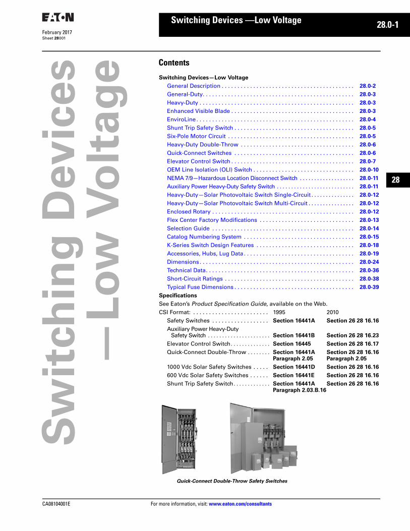
Safety Switches
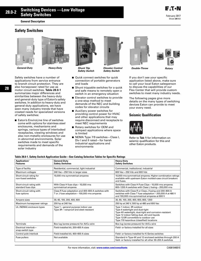
Safety switches have a number of applications from service entrance to branch circuit protection. They are also horsepower rated for use as motor circuit switches. Table 28.0-1 summarizes major differences and similarities between the heavy-duty and general-duty type of Eaton’s safety switches. In addition to heavy-duty and general-duty applications, we have seen many industry trends that have created needs for specialized versions of safety switches:
■ Eaton’s EnviroLine line of switches come with options for stainless steel enclosures, mechanisms and springs, various types of interlocked receptacles, viewing windows and also non-metallic enclosures for use in abnormal environments. Solar switches made to meet specific requirements and demands of the solar industry
■ Quick connect switches for quick connection of portable generators and loads
■ Shunt trippable switches for a quick and safe means to remotely open a switch in an emergency situation
■ Elevator control switches to provide a one-stop method to meet demands of the NEC and building codes for elevator circuits
■ Auxiliary power switches for providing control power for HVAC and other applications that may require disconnect and receptacle to meet NEC requirements
■ Rotary switches for OEM and compact applications where space is limited
■ NEMA Type 7/9 switches—Class I, Div I and II rated—for harsh industrial applications and environments
If you don’t see your specific application listed above, make sure to call your local Eaton salesperson to discuss the capabilities of our Flex Center that will provide custom switches to meet many industry needs.
The following pages give more details on the many types of switching devices Eaton can provide to meet your every need.
Seismic Qualification
Refer to Tab 1 for information on seismic qualification for this and other Eaton products.
Table 28.0-1. Safety Switch Application Guide—See Catalog Selection Tables for Specific Ratings
General-Duty Heavy-Duty Double-Throw RotaryShunt TripSafety Switch
Elevator Control Safety Switch
Application/Features
General-Duty Safety Switches
Heavy-Duty Safety Switches
Type of facility Residential, commercial, light industrial Commercial, institutional, industrial
Maximum voltages 240 Vac—250 Vdc in larger sizes 600 Vac—250 Vdc and 600 Vdc
Short-circuit rating for non-fused switches
10,000 rms symmetrical amperes 10,000 rms symmetrical amperes. Higher combination ratings available with upstream Eaton molded-case circuit breakers and fuses.
Short-circuit rating with standard fuse clips
With Class H fuse clips—10,000 rms symmetrical amperes
Switches with Class H Fuse Clips—10,000 rms amperes 800–1200 A switches with Class L fusing—200,000 rms
Short-circuit rating with fuse options
Class R fuse adaptation and 400–600 A switches with T or J fuse adaptation—100,000 rms amperes
Switches with Class R or Class J fusing and 200–800 A switches with Class T fuse adaptation—200,000 A at 480 V and 100,000 rms symmetrical amperes at 600 V
Ampere sizes 30, 60, 100, 200, 400, 600 30, 60, 100, 200, 400, 600, 800, 1200
Maximum horsepower ratings 200 hp at 240 Vac 250 hp at 240 V, 500 hp at 480 and 600 Vac
UL (NEMA) enclosure types Type 1—general purpose indoor use Type 3R—rainproof and sleet-resistant
Type 1 indoor, 3R outdoor Type 4 watertight and dust-tight Type 4X watertight, dust-tight and corrosion-resistant Type 12 indoor falling dust, dirt and liquids Type 12/3R convertible to outdoor useType 7/9 hazardous (classified) locations
Terminals Box lug (screw pressure) for Al/Cu wire Box lug (screw pressure) for Al/Cu wire
Electrical interlock—snap-switch type
Field-installed kit, 200–600 A sizes Field- or factory-installed for all sizes
Control pole interlock Field-installed kit, 400–600 A sizes Field- or factory-installed for K-Series switches
Fuse pullers Not available Standard in Type 4X and 12 enclosed switches through 200 Afield- or factory-installed for all other 30–200 A switches

CA08104001E For more information, visit: www.eaton.com/consultants
28.0-3February 2017
Switching Devices —Low Voltage
Sheet 28
22
23
24
25
26
27
28
29
30
31
32
33
34
35
36
37
38
39
40
41
42
43
Safety SwitchesGeneral Description—Selection Guide
003
General-Duty
General-Duty (Plug Fuse)
General-Duty (Cartridge Fuse)
For residential and commercial applications. Suitable for light-duty motor circuits and service entrance.
■ 240 Vac■ 30–600 A■ For short-circuit ratings, see
Technical Data■ Suitable for service entrance
applications unless otherwise noted■ Fusible and non-fusible switches
are 100% load break and load make rated
■ The continuous load current of fusible switches is not to exceed 80% of the rating of fuses employed in other than motor circuits. Non-fusible switches are 100% fully rated
■ 200–600 A features K-Series design■ Horsepower rated■ Ample wire bending space provides
for easier installation■ With Class R fuses, switches may be
used on systems capable of delivering 100,000 A rms symmetrical
Note: Plug fuse switches are not service entrance rated.
Heavy-Duty
Heavy-Duty
For heavy commercial and industrial applications where reliable performance and service continuity are critical.
■ 600 Vac, 600 Vdc maximum■ 30–1200 A■ For short-circuit ratings, see
Technical Data■ Horsepower rated■ Fusible and non-fusible switches
are 100% load break and load make rated
■ The continuous load current of fusible switches is not to exceed 80% of the rating of fuses employed in other than motor circuits. Non-fusible switches are 100% fully rated
■ Suitable for service entrance applications unless otherwise noted
■ Visible double break rotary blade mechanism. Two points of contact provide a positive open and close, easier operation, and also help toprevent contact burning for longer contact life
■ Triple padlocking capability. Personnel safety feature because the large hasp can accommodate up to three 3/8-inch (9.5 mm) shank locks. Cabinet door can be further padlocked at the top and bottom
■ Interlocking mechanism. Door cannot be opened when the handle is in the ON position. Built-in defeater mechanism provides for user access when necessary
■ De-ionizing arc chutes. Arc chutes confine and suppress the arcs produced by contacts under load
Enhanced Visible Blade
Advanced Visibility Blade
■ Heavy-duty safety switches with enhanced visible blade provide a highly visible means of disconnect to help improve personnel safety and equipment protection
■ Enhanced visible means of disconnect allows personnel to clearly see that blades are disengaged from stationary contacts when the switch handle is in the OFF position
■ New visible blade design provides increased visibility over each pole, allowing users to clearly see the trailing edge of the blade
■ Material color update from red to yellow creates greater contrast between blades and arc shield
■ Available in 30–1200 A ratings■ Fusible and non-fusible
configurations in two-, three-, four- and six-pole
■ NEMA 1, 3R, 12, 4 and 4X enclosures for robust environmental protection
■ Modifications available such as auxiliary contacts, pilot lights and more. Call the Flex Center at 888-329-9272 or email [email protected]
■ To order safety switches with enhanced visible blade features and no viewing window, the standard heavy-duty catalog number should be used with the addition of a ‘V’ suffix
28.0-4
For more information, visit: www.eaton.com/consultants CA08104001E
February 2017
Switching Devices —Low Voltage
Sheet 28
22
23
24
25
26
27
28
29
30
31
32
33
34
35
36
37
38
39
40
41
42
43
Safety SwitchesGeneral Description—Selection Guide
004
EnviroLine
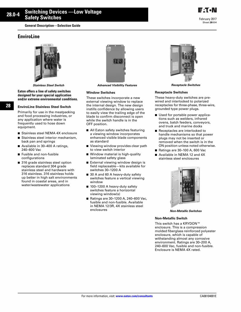
Stainless Steel Switch
Eaton offers a line of safety switches designed for your special application and/or extreme environmental conditions.
EnviroLine Stainless Steel Switch
Primarily for use in the meatpacking and food processing industries, or any application where water is frequently used to hose down equipment.
■ Stainless steel NEMA 4X enclosure■ Stainless steel interior mechanism,
back pan and springs■ Available in 30–400 A ratings,
240–600 Vac■ Fusible and non-fusible
configurations■ 316 grade stainless steel option
replaces standard 304 grade stainless steel and hardware with 316 stainless. 316 stainless holds up better in high salt environments found in coastal areas, and in water/wastewater applications
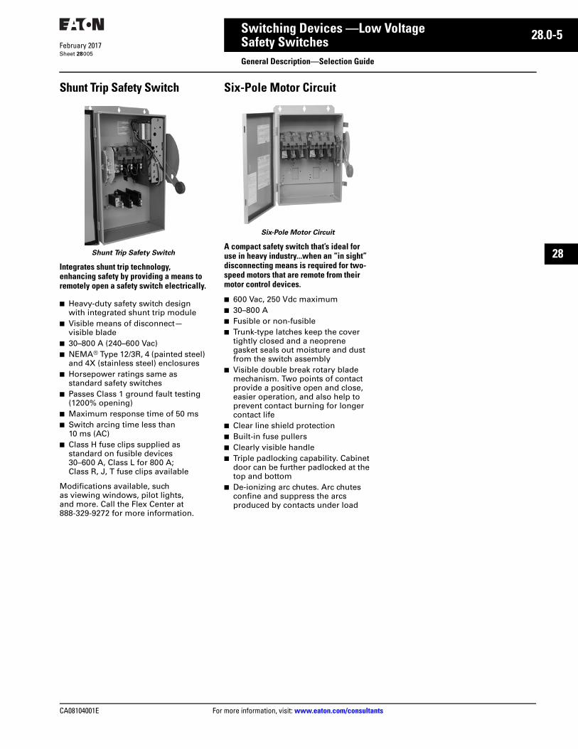
Advanced Visibility Features
Window Switches These switches incorporate a new external viewing window to replace the internal design. The new design instills confidence by allowing users to easily view the trailing edge of the blade to confirm disconnect is open while the switch handle is in the OFF position.
■ All Eaton safety switches featuring a viewing window incorporates enhanced visible blade components as standard
■ Viewing window provides clear path to view switch interior
■ Window material is high-quality laminated safety glass
■ External viewing window design is field replaceable—kits available for switches 30–1200 A
■ 30 A and 60 A heavy-duty safety switches feature a vertical viewing window
■ 100–1200 A heavy-duty safety switches feature a horizontal viewing window(s)
■ Ratings are 30–1200 A, 240–600 Vac, fusible and non-fusible. Available in NEMA 12/3R, 4X stainless steel enclosures
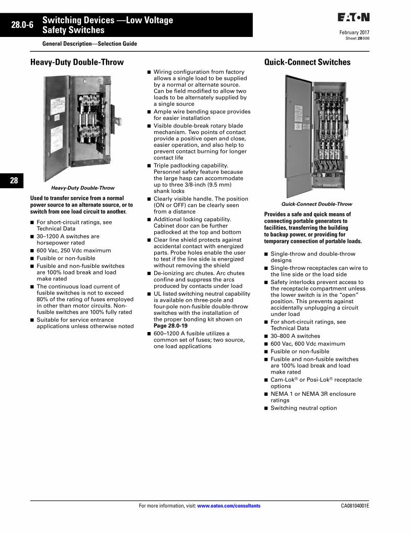
Receptacle Switches
Receptacle Switches
These heavy-duty switches are pre-wired and interlocked to polarized receptacles for three-phase, three-wire, grounded type power plugs.
■ Used for portable power applica-tions such as welders, infrared ovens, batch feeders, conveyors, and truck and marine docks
■ Receptacles are interlocked to handle mechanisms so that power plugs may not be inserted or removed when the switch is in the ON position unless noted otherwise.
■ Ratings are 30–100 A, 600 Vac■ Available in NEMA 12 and 4X
stainless steel enclosures
Non-Metallic Switches
Non-Metallic Switch
This switch has a KRYDON™ enclosure. This is a compression molded fiberglass reinforced polyester enclosure, which is capable of withstanding almost any corrosive environment. Ratings are 30–200 A, 240–600 Vac, fusible and non-fusible. Enclosure is NEMA 4X rated.
CA08104001E For more information, visit: www.eaton.com/consultants
28.0-5February 2017
Switching Devices —Low Voltage
Sheet 28
22
23
24
25
26
27
28
29
30
31
32
33
34
35
36
37
38
39
40
41
42
43
Safety SwitchesGeneral Description—Selection Guide
005
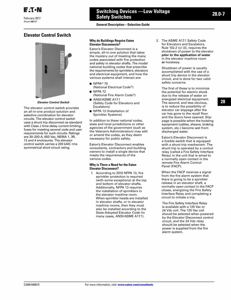
Shunt Trip Safety Switch
Shunt Trip Safety Switch
Integrates shunt trip technology, enhancing safety by providing a means to remotely open a safety switch electrically.
■ Heavy-duty safety switch design with integrated shunt trip module
■ Visible means of disconnect—visible blade
■ 30–800 A (240–600 Vac)■ NEMA® Type 12/3R, 4 (painted steel)
and 4X (stainless steel) enclosures■ Horsepower ratings same as
standard safety switches■ Passes Class 1 ground fault testing
(1200% opening)■ Maximum response time of 50 ms■ Switch arcing time less than
10 ms (AC)■ Class H fuse clips supplied as
standard on fusible devices 30–600 A, Class L for 800 A; Class R, J, T fuse clips available
Modifications available, such as viewing windows, pilot lights, and more. Call the Flex Center at 888-329-9272 for more information.
Six-Pole Motor Circuit
Six-Pole Motor Circuit
A compact safety switch that’s ideal for use in heavy industry...when an “in sight” disconnecting means is required for two-speed motors that are remote from their motor control devices.
■ 600 Vac, 250 Vdc maximum■ 30–800 A■ Fusible or non-fusible■ Trunk-type latches keep the cover
tightly closed and a neoprene gasket seals out moisture and dust from the switch assembly
■ Visible double break rotary blade mechanism. Two points of contact provide a positive open and close, easier operation, and also help toprevent contact burning for longer contact life
■ Clear line shield protection■ Built-in fuse pullers■ Clearly visible handle■ Triple padlocking capability. Cabinet
door can be further padlocked at the top and bottom
■ De-ionizing arc chutes. Arc chutes confine and suppress the arcs produced by contacts under load
28.0-6
For more information, visit: www.eaton.com/consultants CA08104001E
February 2017
Switching Devices —Low Voltage
Sheet 28
22
23
24
25
26
27
28
29
30
31
32
33
34
35
36
37
38
39
40
41
42
43
Safety SwitchesGeneral Description—Selection Guide
006
Heavy-Duty Double-Throw
Heavy-Duty Double-Throw
Used to transfer service from a normal power source to an alternate source, or to switch from one load circuit to another.
■ For short-circuit ratings, see Technical Data
■ 30–1200 A switches are horsepower rated
■ 600 Vac, 250 Vdc maximum■ Fusible or non-fusible■ Fusible and non-fusible switches
are 100% load break and load make rated
■ The continuous load current of fusible switches is not to exceed 80% of the rating of fuses employed in other than motor circuits. Non-fusible switches are 100% fully rated
■ Suitable for service entrance applications unless otherwise noted
■ Wiring configuration from factory allows a single load to be supplied by a normal or alternate source. Can be field modified to allow two loads to be alternately supplied by a single source
■ Ample wire bending space provides for easier installation
■ Visible double-break rotary blade mechanism. Two points of contact provide a positive open and close, easier operation, and also help toprevent contact burning for longer contact life
■ Triple padlocking capability. Personnel safety feature because the large hasp can accommodate up to three 3/8-inch (9.5 mm) shank locks
■ Clearly visible handle. The position (ON or OFF) can be clearly seen from a distance
■ Additional locking capability. Cabinet door can be further padlocked at the top and bottom
■ Clear line shield protects against accidental contact with energized parts. Probe holes enable the user to test if the line side is energized without removing the shield
■ De-ionizing arc chutes. Arc chutes confine and suppress the arcs produced by contacts under load
■ UL listed switching neutral capability is available on three-pole and four-pole non-fusible double-throw switches with the installation of the proper bonding kit shown on Page 28.0-19
■ 600–1200 A fusible utilizes a common set of fuses; two source, one load applications
Quick-Connect Switches
Quick-Connect Double-Throw
Provides a safe and quick means of connecting portable generators to facilities, transferring the building to backup power, or providing for temporary connection of portable loads.
■ Single-throw and double-throw designs
■ Single-throw receptacles can wire to the line side or the load side
■ Safety interlocks prevent access to the receptacle compartment unless the lower switch is in the “open” position. This prevents against accidentally unplugging a circuit under load
■ For short-circuit ratings, see Technical Data
■ 30–800 A switches■ 600 Vac, 600 Vdc maximum■ Fusible or non-fusible■ Fusible and non-fusible switches
are 100% load break and load make rated
■ Cam-Lok® or Posi-Lok® receptacle options
■ NEMA 1 or NEMA 3R enclosure ratings
■ Switching neutral option
CA08104001E For more information, visit: www.eaton.com/consultants
28.0-7February 2017
Switching Devices —Low Voltage
Sheet 28
22
23
24
25
26
27
28
29
30
31
32
33
34
35
36
37
38
39
40
41
42
43
Safety SwitchesGeneral Description—Selection Guide
007
Elevator Control Switch
Elevator Control Switch
The elevator control switch provides an all-in-one product solution and selective coordination for elevator circuits. The elevator control switch uses a shunt trip disconnect as standard with Class J time-delay current-limiting fuses for meeting several code and user requirements for such circuits. Ratings are 30–200 A, 600 Vac, NEMA 1, 3R, 12 and 4 enclosures. The elevator control switch carries a 200 kAIC rms symmetrical short-circuit rating.
Why do Buildings Require Eaton Elevator Disconnects?Eaton’s Elevator Disconnect is a simple, all-in-one solution that takes the mystery out of meeting the many codes associated with fire protection and safety in elevator shafts. The model national building codes that prescribe the requirements for sprinklers, elevators and electrical equipment, and how the various systems shall interact are:
■ NFPA® 70 (National Electrical Code®)
■ NFPA 72 (National Fire Alarm Code®)
■ ANSI/ASME A17.1 (Safety Code for Elevators and Escalators)
■ NFPA 13 (Installation of Sprinkler Systems)
In addition to these national codes, state and local jurisdictions or other agencies of the government (such as the Veteran’s Administration) may edit or amend the codes, as they deem necessary for public safety.
Eaton’s Elevator Disconnect enables consultants, contractors and building owners to install a single device that meets the requirements of the various codes.
Why is There a Need for the EatonElevator Disconnect?1. According to 2010 NFPA 13, fire
sprinkler protection is required (with some exceptions) at the top and bottom of elevator shafts. Additionally, NFPA 13 requires the installation of sprinklers in the elevator machine room. When sprinkler heads are installed in elevator shafts, or in elevator machine rooms, then they must also be installed according to the State-Adopted Elevator Code (in many cases, ANSI/ASME A17.1).
2. The ASME A17.1 Safety Code for Elevators and Escalators, Rule 102.2 (c) (3), requires the shutdown of power to the elevator prior to the application of water in the elevator machine room or hoistway.
Shutdown of power is usually accomplished with the use of a shunt trip device in the elevator circuit, and is done for two valid safety concerns.
The first of these is to minimize the potential for electric shock due to the release of water on energized electrical equipment. The second, and less obvious, is to reduce the possibility of elevator car slippage after the car has gone to the recall floor and the doors have opened. Slip-page is possible when the hoisting equipment (cables, sheave, braking system, etc.) become wet from discharged water.
Eaton’s Elevator Disconnect is a fusible switch that is equipped with a shunt trip mechanism. The shunt trip is operated by a control relay (called a Fire Safety Interface Relay) in the unit that is wired to a normally open contact in the remote Fire Alarm Control Panel (FACP).
When the FACP receives a signal from the fire alarm system that there is going to be a sprinkler release in an elevator shaft, a normally open contact in the FACP closes, energizing the Fire Safety Interface Relay and completing a circuit to initiate a trip.
The Fire Safety Interface Relay is available with a 120 Vac or 24 Vdc coil. The 120 Vac coil should be selected when powered by the Elevator Disconnect control circuit, and the 24 Vdc relay should be selected when the power is supplied from the fire alarm system.
28.0-8
For more information, visit: www.eaton.com/consultants CA08104001E
February 2017
Switching Devices —Low Voltage
Sheet 28
22
23
24
25
26
27
28
29
30
31
32
33
34
35
36
37
38
39
40
41
42
43
Safety SwitchesGeneral Description—Selection Guide
008
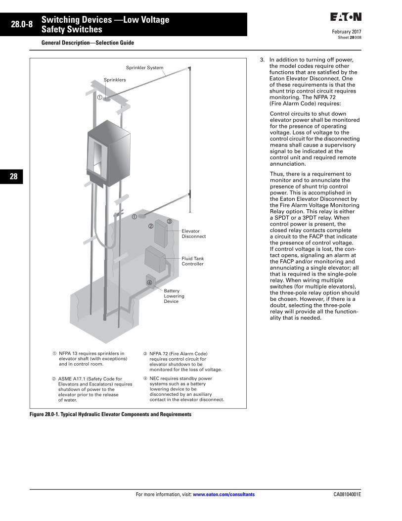
Figure 28.0-1. Typical Hydraulic Elevator Components and Requirements
1
23
1
Sprinkler System
Fluid TankController
ElevatorDisconnect
Battery LoweringDevice
Sprinklers
4
1 NFPA 13 requires sprinklers in elevator shaft (with exceptions) and in control room.
2 ASME A17.1 (Safety Code for Elevators and Escalators) requires shutdown of power to the elevator prior to the release of water.
3 NFPA 72 (Fire Alarm Code) requires control circuit for elevator shutdown to be monitored for the loss of voltage.
4 NEC requires standby power systems such as a battery lowering device to be disconnected by an auxiliary contact in the elevator disconnect.
3. In addition to turning off power, the model codes require other functions that are satisfied by the Eaton Elevator Disconnect. One of these requirements is that the shunt trip control circuit requires monitoring. The NFPA 72 (Fire Alarm Code) requires:
Control circuits to shut down elevator power shall be monitored for the presence of operating voltage. Loss of voltage to the control circuit for the disconnecting means shall cause a supervisory signal to be indicated at the control unit and required remote annunciation.
Thus, there is a requirement to monitor and to annunciate the presence of shunt trip control power. This is accomplished in the Eaton Elevator Disconnect by the Fire Alarm Voltage Monitoring Relay option. This relay is either a SPDT or a 3PDT relay. When control power is present, the closed relay contacts complete a circuit to the FACP that indicate the presence of control voltage. If control voltage is lost, the con-tact opens, signaling an alarm at the FACP and/or monitoring and annunciating a single elevator; all that is required is the single-pole relay. When wiring multiple switches (for multiple elevators), the three-pole relay option should be chosen. However, if there is a doubt, selecting the three-pole relay will provide all the function-ality that is needed.
CA08104001E For more information, visit: www.eaton.com/consultants
28.0-9February 2017
Switching Devices —Low Voltage
Sheet 28
22
23
24
25
26
27
28
29
30
31
32
33
34
35
36
37
38
39
40
41
42
43
Safety SwitchesGeneral Description
009
Additional Requirements and ConcernsMany elevators are equipped with backup power supplies to allow the elevator to be lowered if power is lost. For example, many hydraulic elevators are equipped with a battery system that opens a solenoid to lower the elevator, and then provides power to open the elevator doors.
This battery-lowering device is viewed by the NEC as an “emergency or standby power system,” and is governed by Article 620.91.
4. Paragraph (C) requires that the main disconnect be provided with an auxiliary contact that discon-nects the additional power source from the load when the discon-necting means is in the open position. The purpose of this auxiliary contact is to disconnect the backup power system when the elevator switch is opened to prevent the elevator from auto-matically lowering while being maintained—which would endanger maintenance personnel.
Eaton’s Elevator Disconnect is supplied with a standard set of 1NO and 1NC auxiliary contacts that are wired to the terminal blocks for this feature. Other manufacturers offer this as an option.
An additional concern that is not code related is accidental signaling of a loss of voltage if a switch is turned off for maintenance or testing. For example, if an Eaton Elevator Disconnect is turned off to perform routine maintenance, the control voltage will be disconnected and it will send a signal to the FACP—which may alert the local fire department and initiate a fire call.
To solve this problem, an optional micro switch mounted on the main switch can be supplied and field-wired in parallel with the alarm contact on the Voltage Monitoring relay. Wiring in this fashion would prevent an alarm signal from being sent when the Eaton Elevator Disconnect is turned off for routine maintenance.
An additional standard feature on the Eaton Elevator Disconnect is a Key-To-Test switch to perform a functional test of the operation of the shunt trip. A pilot light signaling that the switch is ON and a neutral lug are the only other available options.
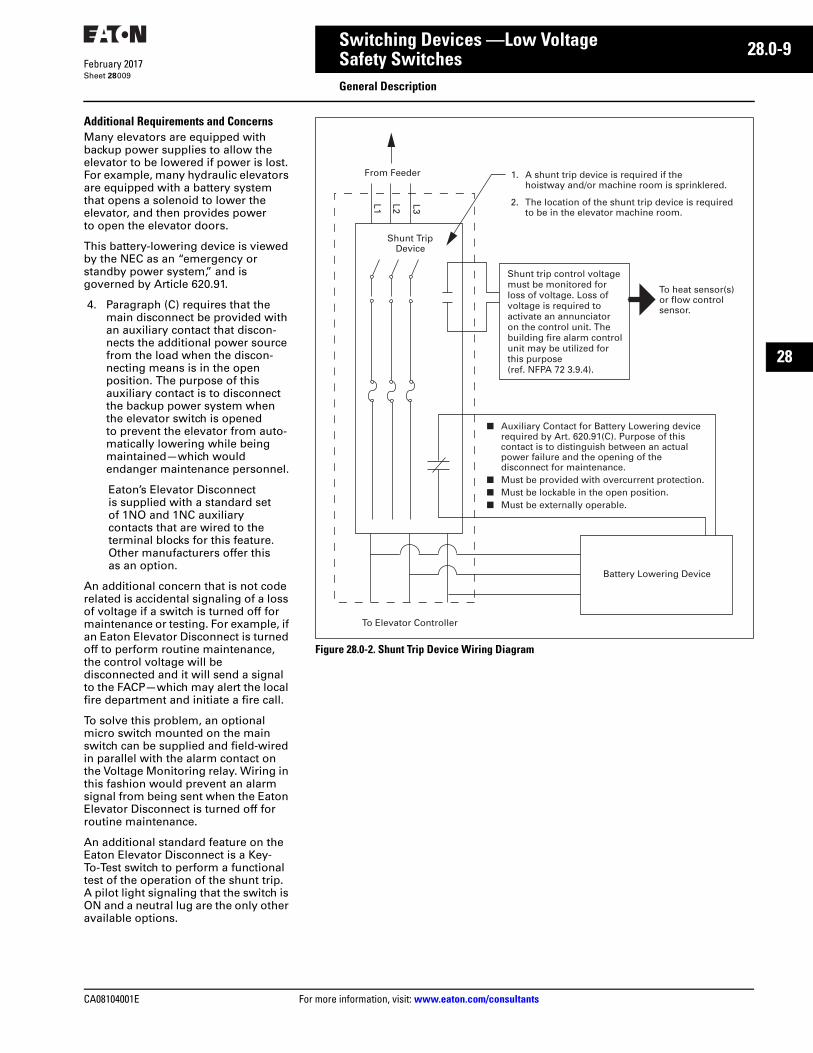
Figure 28.0-2. Shunt Trip Device Wiring Diagram
Shunt TripDevice
From Feeder
L1 L2 L3
Battery Lowering Device
To Elevator Controller
1. A shunt trip device is required if thehoistway and/or machine room is sprinklered.
2. The location of the shunt trip device is requiredto be in the elevator machine room.
To heat sensor(s)or flow controlsensor.
■ Auxiliary Contact for Battery Lowering devicerequired by Art. 620.91(C). Purpose of thiscontact is to distinguish between an actualpower failure and the opening of the disconnect for maintenance.
■ Must be provided with overcurrent protection.■ Must be lockable in the open position.■ Must be externally operable.
Shunt trip control voltage must be monitored for loss of voltage. Loss of voltage is required to activate an annunciator on the control unit. The building fire alarm control unit may be utilized for this purpose (ref. NFPA 72 3.9.4).
28.0-10
For more information, visit: www.eaton.com/consultants CA08104001E
February 2017
Switching Devices —Low Voltage
Sheet 28
22
23
24
25
26
27
28
29
30
31
32
33
34
35
36
37
38
39
40
41
42
43
Safety SwitchesGeneral Description—Selection Guide
010
OEM Line Isolation (OLI) Switch
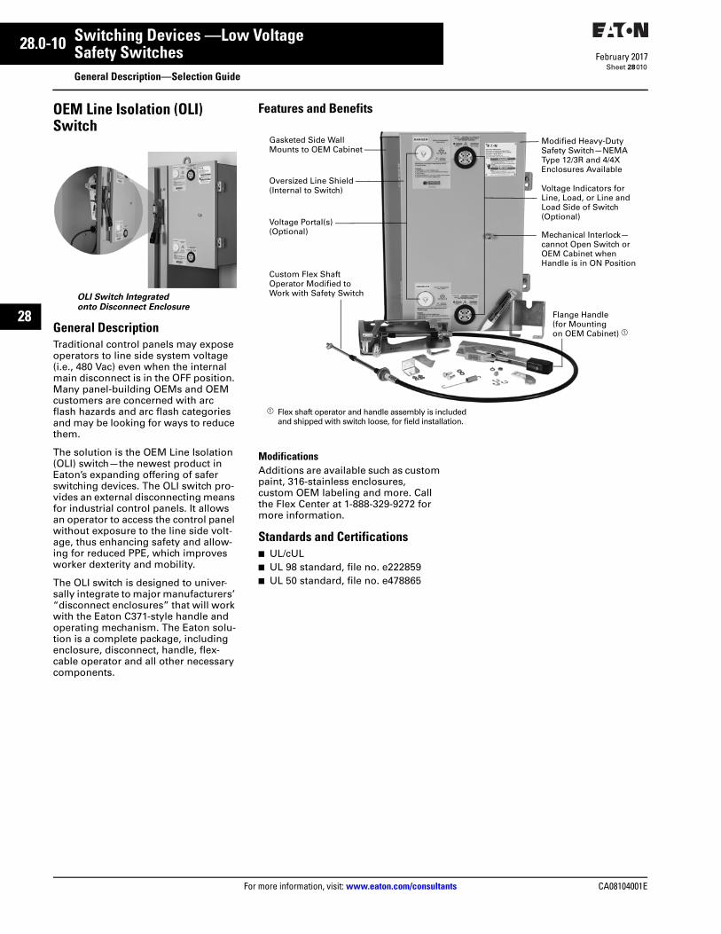
OLI Switch Integrated onto Disconnect Enclosure
General DescriptionTraditional control panels may expose operators to line side system voltage (i.e., 480 Vac) even when the internal main disconnect is in the OFF position. Many panel-building OEMs and OEM customers are concerned with arc flash hazards and arc flash categories and may be looking for ways to reduce them.
The solution is the OEM Line Isolation (OLI) switch—the newest product in Eaton’s expanding offering of safer switching devices. The OLI switch pro-vides an external disconnecting means for industrial control panels. It allows an operator to access the control panel without exposure to the line side volt-age, thus enhancing safety and allow-ing for reduced PPE, which improves worker dexterity and mobility.
The OLI switch is designed to univer-sally integrate to major manufacturers’ “disconnect enclosures” that will work with the Eaton C371-style handle and operating mechanism. The Eaton solu-tion is a complete package, including enclosure, disconnect, handle, flex-cable operator and all other necessary components.
Features and Benefits
ModificationsAdditions are available such as custom paint, 316-stainless enclosures, custom OEM labeling and more. Call the Flex Center at 1-888-329-9272 for more information.
Standards and Certifications■ UL/cUL■ UL 98 standard, file no. e222859■ UL 50 standard, file no. e478865
Gasketed Side Wall Mounts to OEM Cabinet
Oversized Line Shield(Internal to Switch)
Voltage Portal(s) (Optional)
Custom Flex Shaft Operator Modified to Work with Safety Switch
Modified Heavy-Duty Safety Switch—NEMA Type 12/3R and 4/4X Enclosures Available
Voltage Indicators for Line, Load, or Line and Load Side of Switch (Optional)
Mechanical Interlock—cannot Open Switch or OEM Cabinet when Handle is in ON Position
Flange Handle(for Mounting on OEM Cabinet) a
a Flex shaft operator and handle assembly is included and shipped with switch loose, for field installation.
CA08104001E For more information, visit: www.eaton.com/consultants
28.0-11February 2017
Switching Devices —Low Voltage
Sheet 28
22
23
24
25
26
27
28
29
30
31
32
33
34
35
36
37
38
39
40
41
42
43
Safety SwitchesGeneral Description—Selection Guide
011
NEMA 7/9—Hazardous Location Disconnect Switch
NEMA Type 7/9
■ The cast aluminum enclosure is ideally suited for harsh industrial applications including petrochemi-cal facilities, mining operations, pharmaceutical plants and waste-water treatment facilities. Eaton’s Type DS switch is used as the switching device. Ratings are 30–100 A, 600 Vac, fusible and non-fusible
Certifications and Compliances■ Class I, Divisions 1 and 2,
Groups B, C, D■ Class I, Zones 1 and 2■ Class II, Division 1, Groups E, F, G■ Class III■ NEMA 3, 3R, 4, 4X, 7BCD, 9EFG■ UL® standard: 1203■ cUL® to CSA® C22.2 No. 30
Standard Materials■ Body and cover—copper-free
aluminum■ Gasket—neoprene■ Cover bolts—steel, stainless steel■ Hinges—stainless steel■ Mounting plate sheet—aluminum■ Rotary actuating handle—aluminum
Standard Finishes■ Copper-free aluminum—natural■ Steel—electrogalvanized
Auxiliary Power Heavy-Duty Safety Switch
Auxiliary Power Heavy-Duty Safety Switch
NEC Section 210.63 for Heating, Air-Conditioning and Refrigeration Equipment requires a 125 V, single-phase, 15 A- or 20 A-rated receptacle outlet be installed at an accessible location for the servicing of heating, air-conditioning and refrigeration equipment. The receptacle must be located on the same level and within 25 ft (7.5 m) of the heating, air-conditioning and refrigeration equipment. The receptacle outlet is not to be connected to the load side of the equipment disconnecting means.
The Auxiliary Power Heavy-Duty Safety Switch combines a safety switch, 2 kVA control transformer, and 15 A GFI receptacle in a single product. Ratings are 30–200 A, 240 or 600 Vac, NEMA 3R outdoor enclosures. The auxiliary circuit is tapped off of the line side of the safety switch and can be operated independently of the main switch circuit. Auxiliary circuit voltages are available at either 208, 240, 480 or 600 V. In 480 V and 600 V applications, the auxiliary circuit disconnect and overcurrent protection are provided by a fusible deadfront disconnect switch with Class J fuses. The short-circuit rating is 200 kAIC. 208 V and 240 V applications have a molded-case breaker with a 100 kAIC rating as the auxiliary circuit disconnect. The use of the Auxiliary Power Heavy-Duty Safety Switch eliminates the need for running a separate 120 V circuit common to rooftop air-conditioning applications.
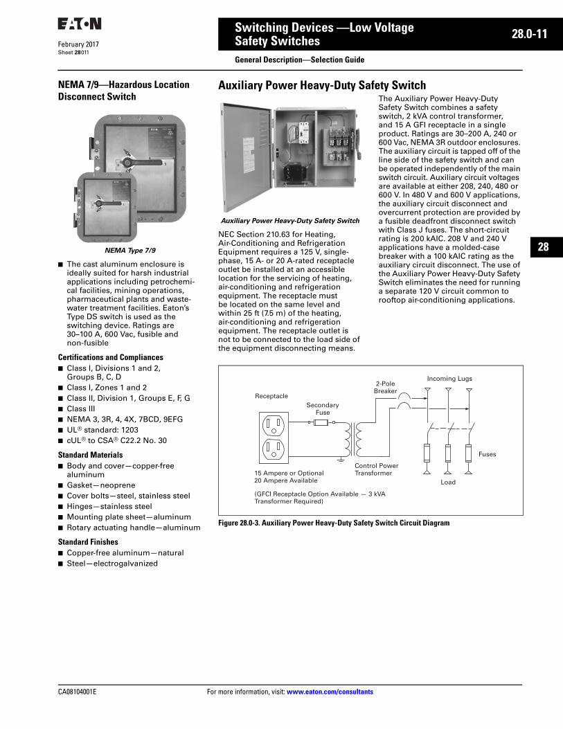
Figure 28.0-3. Auxiliary Power Heavy-Duty Safety Switch Circuit Diagram
Incoming Lugs
Fuses
Load
Control PowerTransformer
SecondaryFuse
Receptacle
15 Ampere or Optional20 Ampere Available
(GFCI Receptacle Option Available — 3 kVATransformer Required)
2-PoleBreaker
28.0-12
For more information, visit: www.eaton.com/consultants CA08104001E
February 2017
Switching Devices —Low Voltage
Sheet 28
22
23
24
25
26
27
28
29
30
31
32
33
34
35
36
37
38
39
40
41
42
43
Safety SwitchesGeneral Description—Selection Guide
012
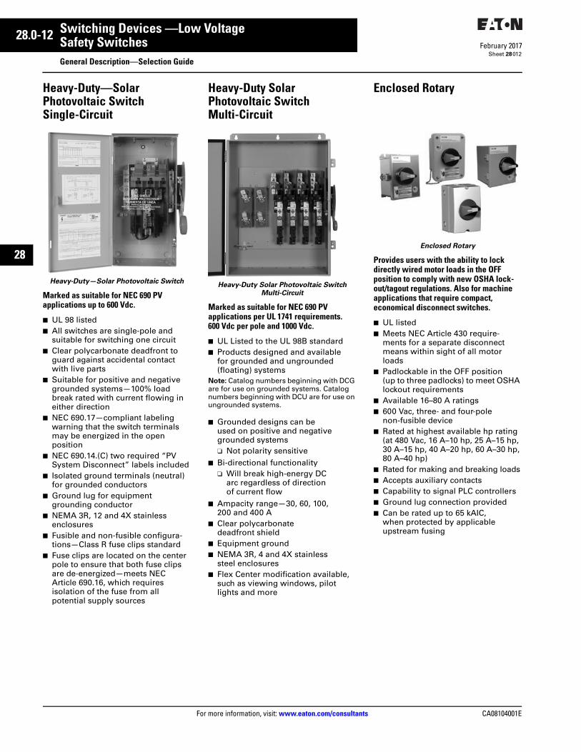
Heavy-Duty—Solar Photovoltaic SwitchSingle-Circuit
Heavy-Duty—Solar Photovoltaic Switch
Marked as suitable for NEC 690 PV applications up to 600 Vdc.
■ UL 98 listed■ All switches are single-pole and
suitable for switching one circuit■ Clear polycarbonate deadfront to
guard against accidental contact with live parts
■ Suitable for positive and negative grounded systems—100% load break rated with current flowing in either direction
■ NEC 690.17—compliant labeling warning that the switch terminals may be energized in the open position
■ NEC 690.14.(C) two required “PV System Disconnect” labels included
■ Isolated ground terminals (neutral) for grounded conductors
■ Ground lug for equipment grounding conductor
■ NEMA 3R, 12 and 4X stainless enclosures
■ Fusible and non-fusible configura-tions—Class R fuse clips standard
■ Fuse clips are located on the center pole to ensure that both fuse clips are de-energized—meets NEC Article 690.16, which requires isolation of the fuse from all potential supply sources
Heavy-Duty Solar Photovoltaic Switch Multi-Circuit
Heavy-Duty Solar Photovoltaic Switch Multi-Circuit
Marked as suitable for NEC 690 PV applications per UL 1741 requirements. 600 Vdc per pole and 1000 Vdc.
■ UL Listed to the UL 98B standard■ Products designed and available
for grounded and ungrounded (floating) systems
Note: Catalog numbers beginning with DCG are for use on grounded systems. Catalog numbers beginning with DCU are for use on ungrounded systems.
■ Grounded designs can be used on positive and negative grounded systems❑ Not polarity sensitive
■ Bi-directional functionality❑ Will break high-energy DC
arc regardless of direction of current flow
■ Ampacity range—30, 60, 100, 200 and 400 A
■ Clear polycarbonate deadfront shield
■ Equipment ground■ NEMA 3R, 4 and 4X stainless
steel enclosures■ Flex Center modification available,
such as viewing windows, pilot lights and more
Enclosed Rotary
Enclosed Rotary
Provides users with the ability to lock directly wired motor loads in the OFF position to comply with new OSHA lock-out/tagout regulations. Also for machine applications that require compact, economical disconnect switches.
■ UL listed■ Meets NEC Article 430 require-
ments for a separate disconnect means within sight of all motor loads
■ Padlockable in the OFF position (up to three padlocks) to meet OSHA lockout requirements
■ Available 16–80 A ratings■ 600 Vac, three- and four-pole
non-fusible device■ Rated at highest available hp rating
(at 480 Vac, 16 A–10 hp, 25 A–15 hp, 30 A–15 hp, 40 A–20 hp, 60 A–30 hp, 80 A–40 hp)
■ Rated for making and breaking loads■ Accepts auxiliary contacts■ Capability to signal PLC controllers■ Ground lug connection provided■ Can be rated up to 65 kAIC,
when protected by applicable upstream fusing
CA08104001E For more information, visit: www.eaton.com/consultants
28.0-13February 2017
Switching Devices —Low Voltage
Sheet 28
22
23
24
25
26
27
28
29
30
31
32
33
34
35
36
37
38
39
40
41
42
43
Safety SwitchesFactory Modifications—Flex Center Facility
013
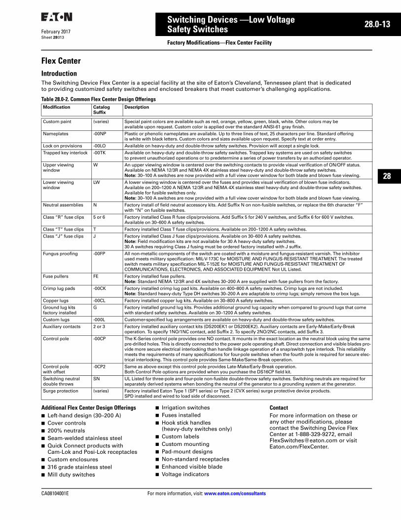
Flex CenterIntroductionThe Switching Device Flex Center is a special facility at the site of Eaton’s Cleveland, Tennessee plant that is dedicated to providing customized safety switches and enclosed breakers that meet customer’s challenging applications.
Table 28.0-2. Common Flex Center Design Offerings
Additional Flex Center Design Offerings■ Left-hand design (30–200 A)■ Cover controls■ 200% neutrals■ Seam-welded stainless steel■ Quick Connect products with
Cam-Lok and Posi-Lok receptacles■ Custom enclosures■ 316 grade stainless steel■ Mill duty switches
■ Irrigation switches■ Fuses installed■ Hook stick handles
(heavy-duty switches only)■ Custom labels■ Custom mounting■ Pad-mount designs■ Non-standard receptacles■ Enhanced visible blade■ Voltage indicators
ContactFor more information on these or any other modifications, please contact the Switching Device Flex Center at 1-888-329-9272, [email protected] or visit Eaton.com/FlexCenter.
Modification Catalog Suffix
Description
Custom paint (varies) Special paint colors are available such as red, orange, yellow, green, black, white. Other colors may be available upon request. Custom color is applied over the standard ANSI-61 gray finish.
Nameplates -00NP Plastic or phenolic nameplates are available. Up to three lines of text, 25 characters per line. Standard offering is white with black letters. Custom colors and sizes available upon request. Specify text at order entry.
Lock on provisions -00LO Available on heavy-duty and double-throw safety switches. Provision will accept a single lock.
Trapped key interlock -00TK Available on heavy-duty and double-throw safety switches. Trapped key systems are used on safety switches to prevent unauthorized operations or to predetermine a series of power transfers by an authorized operator.
Upper viewing window
W An upper viewing window is centered over the switching contacts to provide visual verification of ON/OFF status. Available on NEMA 12/3R and NEMA 4X stainless steel heavy-duty and double-throw safety switches. Note: 30–100 A switches are now provided with a full view cover window for both blade and blown fuse viewing.
Lower viewing window
LW A lower viewing window is centered over the fuses and provides visual verification of blown fuse indicators. Available on 200–1200 A NEMA 12/3R and NEMA 4X stainless steel heavy-duty and double-throw safety switches. Available for fusible switches only.Note: 30–100 A switches are now provided with a full view cover window for both blade and blown fuse viewing.
Neutral assemblies N Factory install of field neutral accessory kits. Add Suffix N on non-fusible switches, or replace the 6th character “F” with “N” on fusible switches.
Class “R” fuse clips 5 or 6 Factory installed Class R fuse clips/provisions. Add Suffix 5 for 240 V switches, and Suffix 6 for 600 V switches. Available on 30–600 A safety switches.
Class “T” fuse clips T Factory installed Class T fuse clips/provisions. Available on 200–1200 A safety switches.
Class “J” fuse clips J Factory installed Class J fuse clips/provisions. Available on 30–600 A safety switches.Note: Field modification kits are not available for 30 A heavy-duty safety switches. 30 A switches requiring Class J fusing must be ordered factory installed with J suffix.
Fungus proofing -00FP All non-metallic components of the switch are coated with a moisture and fungus-resistant varnish. The inhibitor used meets military specification: MIL-V-173C for MOISTURE AND FUNGUS-RESISTANT TREATMENT. The treated switch meets military specification MIL-T-152E for MOISTURE AND FUNGUS-RESISTANT TREATMENT OF COMMUNICATIONS, ELECTRONICS, AND ASSOCIATED EQUIPMENT. Not UL Listed.
Fuse pullers FE Factory installed fuse pullers.Note: Standard NEMA 12/3R and 4X switches 30–200 A are supplied with fuse pullers from the factory.
Crimp lug pads -00CK Factory installed crimp lug pad kits. Available on 400–800 A safety switches. Crimp lugs are not included.Note: Standard heavy-duty Type DH switches 30–200 A are adaptable to crimp lugs; simply remove the box lugs.
Copper lugs -00CL Factory installed copper lug kits. Available on 30–800 A safety switches.
Ground lug kits factory installed
G Factory installed ground lug kits. Provides additional ground lug capacity when compared to ground lugs that come with standard safety switches. Available on 30–1200 A safety switches.
Custom lugs -000L Customer-specified lug arrangements are available on heavy-duty and double-throw safety switches.
Auxiliary contacts 2 or 3 Factory installed auxiliary contact kits (DS200EK1 or DS200EK2). Auxiliary contacts are Early-Make/Early-Break operation. To specify 1NO/1NC contact, add Suffix 2. To specify 2NO/2NC contacts, add Suffix 3.
Control pole -00CP The K-Series control pole provides one NO contact. It mounts in the exact location as the neutral block using the same pre-drilled holes. This is directly connected to the power pole operating shaft. Direct connection and visible blades pro-vide more secure electrical interlocking than handle linkage operation of a snap/switch type interlock. This reliability meets the requirements of many specifications for four-pole switches when the fourth pole is required for secure elec-trical interlocking. This control pole provides Same-Make/Same-Break operation.
Control pole with offset
-0CP2 Same as above except this control pole provides Late-Make/Early-Break operation. Both Control Pole options are provided when you purchase the DS16CP field kit.
Switching neutral double throws
SN UL Listed for three-pole and four-pole non-fusible double-throw safety switches. Switching neutrals are required for separately derived systems when bonding the neutral of the generator to a grounding system at the generator.
Surge protection (varies) Factory installed Eaton Type 1 (SP1 series) or Type 2 (CVX series) surge protective device products. SPD installed and wired to load side of disconnect.
28.0-14
For more information, visit: www.eaton.com/consultants CA08104001E
February 2017
Switching Devices —Low Voltage
Sheet 28
22
23
24
25
26
27
28
29
30
31
32
33
34
35
36
37
38
39
40
41
42
43
Safety SwitchesGeneral Description—Selection Guide
014
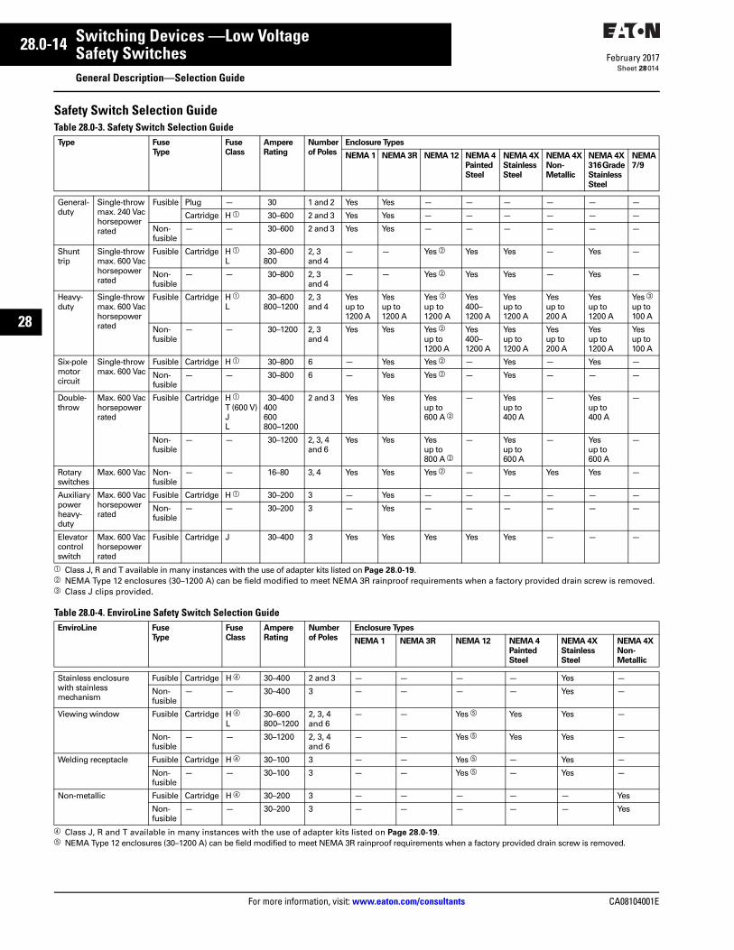
Safety Switch Selection GuideTable 28.0-3. Safety Switch Selection Guide
a Class J, R and T available in many instances with the use of adapter kits listed on Page 28.0-19.b NEMA Type 12 enclosures (30–1200 A) can be field modified to meet NEMA 3R rainproof requirements when a factory provided drain screw is removed.c Class J clips provided.
Table 28.0-4. EnviroLine Safety Switch Selection Guide
d Class J, R and T available in many instances with the use of adapter kits listed on Page 28.0-19.e NEMA Type 12 enclosures (30–1200 A) can be field modified to meet NEMA 3R rainproof requirements when a factory provided drain screw is removed.
Type Fuse Type
FuseClass
AmpereRating
Numberof Poles
Enclosure Types
NEMA 1 NEMA 3R NEMA 12 NEMA 4PaintedSteel
NEMA 4XStainlessSteel
NEMA 4XNon-Metallic
NEMA 4X316 Grade Stainless Steel
NEMA 7/9
General- duty
Single-throwmax. 240 Vachorsepowerrated
Fusible Plug — 30 1 and 2 Yes Yes — — — — — —
Cartridge H a 30–600 2 and 3 Yes Yes — — — — — —
Non-fusible
— — 30–600 2 and 3 Yes Yes — — — — — —
Shunttrip
Single-throwmax. 600 Vachorsepowerrated
Fusible Cartridge H aL
30–600800
2, 3 and 4
— — Yes b Yes Yes — Yes —
Non-fusible
— — 30–800 2, 3 and 4
— — Yes b Yes Yes — Yes —
Heavy- duty
Single-throwmax. 600 Vachorsepowerrated
Fusible Cartridge H aL
30–600800–1200
2, 3 and 4
Yesup to1200 A
Yesup to1200 A
Yes bup to1200 A
Yes400–1200 A
Yesup to1200 A
Yesup to200 A
Yesup to1200 A
Yes cup to100 A
Non-fusible
— — 30–1200 2, 3 and 4
Yes Yes Yes bup to1200 A
Yes400–1200 A
Yesup to1200 A
Yesup to200 A
Yesup to1200 A
Yesup to100 A
Six-polemotorcircuit
Single-throwmax. 600 Vac
Fusible Cartridge H a 30–800 6 — Yes Yes b — Yes — Yes —
Non-fusible
— — 30–800 6 — Yes Yes b — Yes — — —
Double-throw
Max. 600 Vachorsepowerrated
Fusible Cartridge H aT (600 V)JL
30–400400600800–1200
2 and 3 Yes Yes Yesup to 600 A b
— Yesup to 400 A
— Yesup to 400 A
—
Non-fusible
— — 30–1200 2, 3, 4and 6
Yes Yes Yesup to 800 A b
— Yesup to 600 A
— Yesup to 600 A
—
Rotary switches
Max. 600 Vac Non-fusible
— — 16–80 3, 4 Yes Yes Yes b — Yes Yes Yes —
Auxiliarypowerheavy-duty
Max. 600 Vachorsepowerrated
Fusible Cartridge H a 30–200 3 — Yes — — — — — —
Non-fusible
— — 30–200 3 — Yes — — — — — —
Elevatorcontrolswitch
Max. 600 Vachorsepowerrated
Fusible Cartridge J 30–400 3 Yes Yes Yes Yes Yes — — —
EnviroLine Fuse Type
FuseClass
AmpereRating
Numberof Poles
Enclosure Types
NEMA 1 NEMA 3R NEMA 12 NEMA 4Painted Steel
NEMA 4XStainless Steel
NEMA 4XNon-Metallic
Stainless enclosurewith stainless mechanism
Fusible Cartridge H d 30–400 2 and 3 — — — — Yes —
Non-fusible
— — 30–400 3 — — — — Yes —
Viewing window Fusible Cartridge H dL
30–600800–1200
2, 3, 4 and 6
— — Yes e Yes Yes —
Non-fusible
— — 30–1200 2, 3, 4 and 6
— — Yes e Yes Yes —
Welding receptacle Fusible Cartridge H d 30–100 3 — — Yes e — Yes —
Non-fusible
— — 30–100 3 — — Yes e — Yes —
Non-metallic Fusible Cartridge H d 30–200 3 — — — — — Yes
Non-fusible
— — 30–200 3 — — — — — Yes
CA08104001E For more information, visit: www.eaton.com/consultants
28.0-15February 2017
Switching Devices —Low Voltage
Sheet 28
22
23
24
25
26
27
28
29
30
31
32
33
34
35
36
37
38
39
40
41
42
43
Safety SwitchesGeneral Description—Catalog Numbering System
015
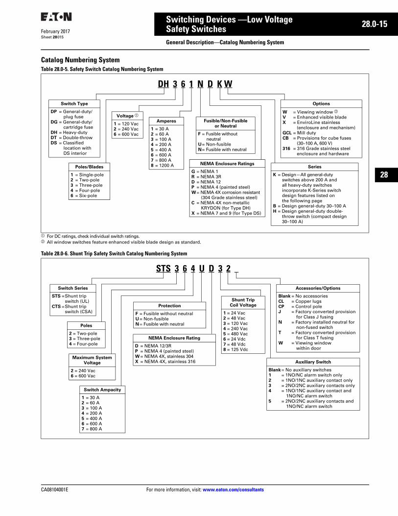
Catalog Numbering SystemTable 28.0-5. Safety Switch Catalog Numbering System
a For DC ratings, check individual switch ratings.b All window switches feature enhanced visible blade design as standard.
Table 28.0-6. Shunt Trip Safety Switch Catalog Numbering System
Series
K = Design—All general-duty switches above 200 A and all heavy-duty switches incorporate K-Series switch design features listed on the following page
B = Design general-duty 30–100 AH = Design general-duty double-
throw switch (compact design 30–100 A)
Fusible/Non-Fusibleor Neutral
F = Fusible without neutral
U= Non-fusibleN= Fusible with neutral
NEMA Enclosure Ratings
G = NEMA 1R = NEMA 3RD = NEMA 12P = NEMA 4 (painted steel)W= NEMA 4X corrosion resistant
(304 Grade stainless steel)C = NEMA 4X non-metallic
KRYDON (for Type DH)X = NEMA 7 and 9 (for Type DS)
Switch Type
DP = General-duty/plug fuse
DG = General-duty/cartridge fuse
DH = Heavy-dutyDT = Double-throwDS = Classified
location withDS interior
Poles/Blades
1 = Single-pole2 = Two-pole3 = Three-pole4 = Four-pole6 = Six-pole
Voltage a
1 = 120 Vac2 = 240 Vac6 = 600 Vac
Amperes
1 = 30 A2 = 60 A3 = 100 A4 = 200 A5 = 400 A6 = 600 A7 = 800 A8 = 1200 A
DH 3 6 1 N D K W
Options
W = Viewing window bV = Enhanced visible bladeX = EnviroLine stainless
(enclosure and mechanism)GCL = Mill dutyCB = Provisions for cube fuses
(30–100 A, 600 V)316 = 316 Grade stainless steel
enclosure and hardware
Shunt TripCoil Voltage
1 = 24 Vac2 = 48 Vac3 = 120 Vac4 = 240 Vac5 = 480 Vac6 = 24 Vdc7 = 48 Vdc8 = 125 Vdc
Protection
F = Fusible without neutralU = Non-fusibleN = Fusible with neutral
Switch Series
STS =Shunt tripswitch (UL)
CTS =Shunt tripswitch (CSA)
Poles
2 = Two-pole3 = Three-pole4 = Four-pole
Maximum System Voltage
2 = 240 Vac6 = 600 Vac
Switch Ampacity
1 = 30 A2 = 60 A3 = 100 A4 = 200 A5 = 400 A6 = 600 A7 = 800 A
Auxiliary Switch
Blank = No auxiliary switches1 = 1NO/NC alarm switch only2 = 1NO/1NC auxiliary contact only3 = 2NO/2NC auxiliary contacts only4 = 1NO/1NC auxiliary contact and
1NO/NC alarm switch5 = 2NO/2NC auxiliary contacts and
1NO/NC alarm switch
Accessories/Options
Blank = No accessoriesCL = Copper lugsCP = Control poleJ = Factory converted provision
for Class J fusingN = Factory installed neutral for
non-fused switchT = Factory converted provision
for Class T fusingW = Viewing window
within door
NEMA Enclosure Rating
D = NEMA 12/3RP = NEMA 4 (painted steel)W = NEMA 4X, stainless 304X = NEMA 4X, stainless 316
STS 3 6 4 U D 3 2

28.0-16
For more information, visit: www.eaton.com/consultants CA08104001E
February 2017
Switching Devices —Low Voltage
Sheet 28
22
23
24
25
26
27
28
29
30
31
32
33
34
35
36
37
38
39
40
41
42
43
Safety SwitchesGeneral Description—Catalog Numbering System
016
Table 28.0-7. Quick-Connect Safety Switch Catalog Numbering System
a When upper and lower switches are the same, the switch configuration is consolidated in one letter (e.g.,”U” not “UU”). Also, a switch with a neutral will have either a solid neutral or a switched neutral, not both. Lastly, a switched neutral pole is never fused.
b Heavy-duty single-throw switches will not have a lower switch option.c This field is only used when a switch is completely non-fused.
Table 28.0-8. Elevator Control Switch Catalog Numbering System
d 100 VA with primary and secondary fusing (120 V secondary).e To monitor shunt trip voltage.f NEMA 1 standard with no suffix designation required.Note: All modules are three-pole, 600 V and contain a key to test switch and mechanically interlocked auxiliary contact as standard.
Series
K = KUpper Switch a
U = Non-fusibleF = FusibleN = Fusible with solid neutralSN = Fusible with switched neutral
Enclosure
G = NEMA 1R = NEMA 3R
Switch Type
DT = Heavy-dutydouble-throw
DH = Heavy-dutysingle-throw
Poles
2 = Two-pole3 = Three-pole4 = Four-pole
Maximum Voltage
2 = 240 Vac6 = 600 Vac
Switch Ampacity
3 = 100 A4 = 200 A5 = 400 A6 = 600 A7 = 800 A
Neutral c
Blank = No neutral or included with switch designation
N = Solid neutralSN = Switched neutral
Receptacle Type
LC = Cam-LokLCR = Cam-Lok reverse pinLP = Posi-LokPLR = Posi-Lok reverse pin
Lower Switch ab
U = Non-fusibleF = FusibleN = Fusible with solid neutralSN = Fusible with switched neutral
DT 3 6 5 N U R K LC
ES 1 T2 R2 G F1 R N B
Switch Type
ES = Elevator control switch
Amperes
1 = 30 A2 = 60 A3 = 100 A4 = 200 A5 = 400 A
Industrial Control
Transformer d
T2 = 208 VT3 = 240 VT1 = 480 VT4 = 600 V
Fire SafetyInterface Relay
(3PDT, 10 A, 120 V)
R2 = 24 Vdc coilR1 = 120 Vac coil
Pilot LightON
G = GreenR = RedW = White
Fire Alarm Voltage
Monitoring Relay e
F1 = Single-poleF3 = Three-pole
Enclosure Options f
3 = NEMA 3RD = NEMA 12P = NEMA 4 painted steelW = NEMA 4X stainless
Auxiliary Contacts1NO/1NC
B = Main switch
Isolated Full Capacity Neutral Lug
N = Neutral lug
CA08104001E For more information, visit: www.eaton.com/consultants
28.0-17February 2017
Switching Devices —Low Voltage
Sheet 28
22
23
24
25
26
27
28
29
30
31
32
33
34
35
36
37
38
39
40
41
42
43
Safety SwitchesGeneral Description—Catalog Numbering System
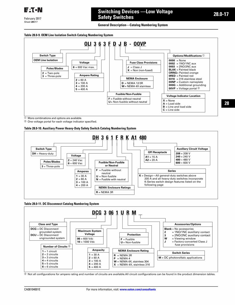
017
Table 28.0-9. OEM Line Isolation Switch Catalog Numbering System
a More combinations and options are available.b One voltage portal for each voltage indicator specified.
Table 28.0-10. Auxiliary Power Heavy-Duty Safety Switch Catalog Numbering System
Table 28.0-11. DC Disconnect Catalog Numbering System
c Not all configurations for ampere rating and number of circuits are available.All circuit configurations can be found in the product dimension tables.
Voltage Indicator Location
X = NoneA = Load sideB = Line and load sideC = Line side
Fusible/Non-Fusible
F = Fusible without neutralU= Non-fusible without neutral
NEMA Enclosure
D = NEMA 12/3RW= NEMA 4X stainless
Switch Type
OEM Line Isolation
Poles/Blades
2 = Two-pole3 = Three-pole
Voltage
6 = 600 Vac max.
Ampere Rating
2 = 60 A3 = 100 A4 = 200 A5 = 400 A
OLI 3 6 3 F D J B - OOVP
Options/Modifications a
0000 = None0002 = 1NO/1NC aux0003 = 2NO/2NC auxBLAK = Painted blackORNG= Painted orange0RED = Painted red0316 = 316 stainless steel00NP = Custom nameplate000G = Additional grounding00VP = Voltage portal b
Fuse Class Provisions
J = Class JX = Non (non-fused)
Series
K = Design—All general-duty switches above 200 A and all heavy-duty switches incorporate K-Series switch design features listed on the following page
Fusible/Non-Fusibleor Neutral
F = Fusible without neutral
U = Non-fusibleN = Fusible with neutral
NEMA Enclosure Ratings
R = NEMA 3R
Switch Type
DH = Heavy-duty
Poles/Blades
3 = Three-pole
Voltage
2 = 240 Vac6 = 600 Vac
Amperes
1 = 30 A2 = 60 A3 = 100 A4 = 200 A
DH 3 6 1 F R K A1 480
Auxiliary Circuit Voltage
208 = 208 V240 = 240 V480 = 480 V600 = 600 V
GFI Receptacle
A1 = 15 AA2 = 20 A
Protection
F = Fusible U = Non-fusible
Class and Type
DCG = DC Disconnect/grounded system
DCU = DC Disconnect/ungrounded system
Number of Circuits c
1 = 1 circuit2 = 2 circuits3 = 3 circuits4 = 4 circuits5 = 5 circuits6 = 6 circuits
Maximum System Voltage
06 = 600 Vdc10 = 1000 Vdc
Ampacity
1 = 30 A2 = 60 A3 = 100 A4 = 200 A5 = 400 A
Switch Series
M = DC photovoltaic applications
Accessories/Options
Blank = No accessories2 = 1NO/1NC auxiliary contact3 = 2NO/2NC auxiliary contactW = Viewing windowJ = Factory-converted Class J
fuse provisions
NEMA Enclosure Rating
R = NEMA 3RP = NEMA 4W = NEMA 4X, stainless 304X = NEMA 4X, stainless 316
DCG 3 06 1 U R M
28.0-18
For more information, visit: www.eaton.com/consultants CA08104001E
February 2017
Switching Devices —Low Voltage
Sheet 28
22
23
24
25
26
27
28
29
30
31
32
33
34
35
36
37
38
39
40
41
42
43
Safety SwitchesGeneral Description
018
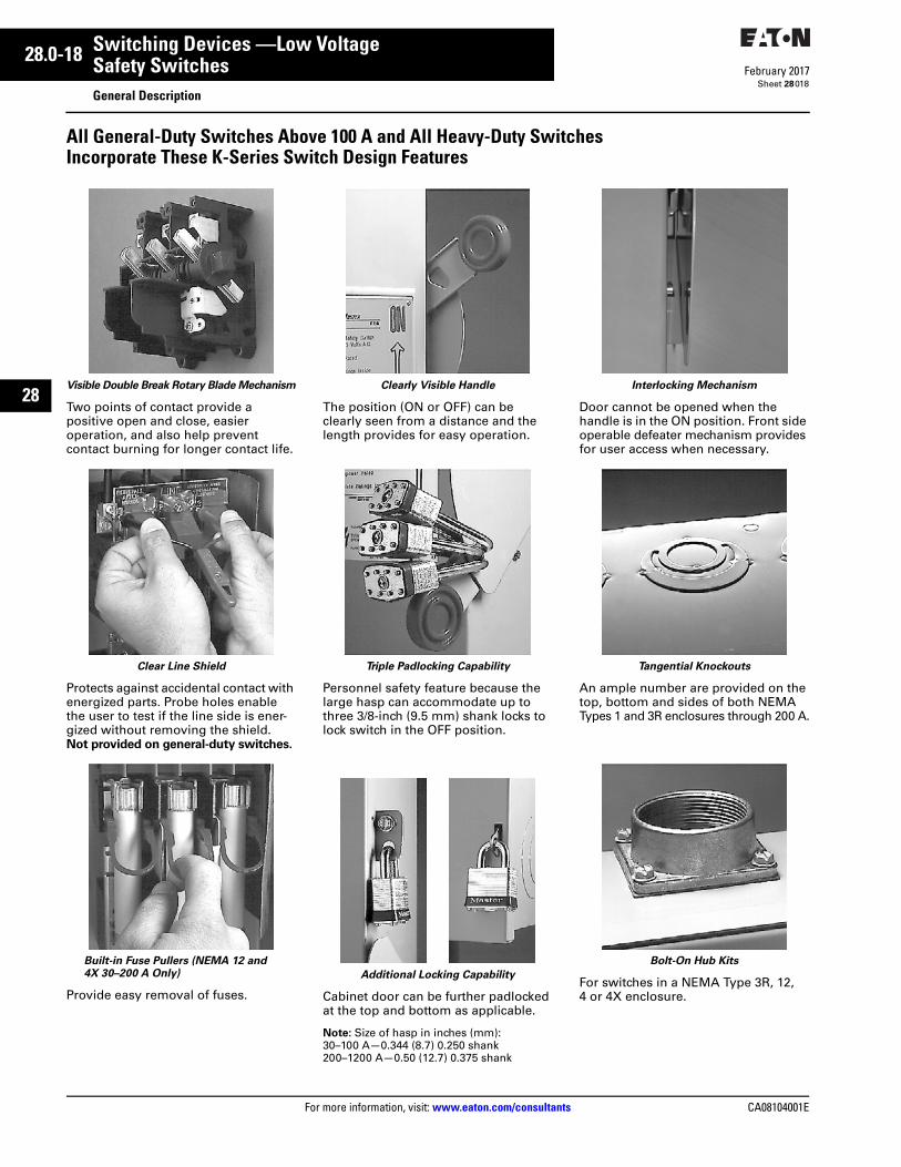
All General-Duty Switches Above 100 A and All Heavy-Duty SwitchesIncorporate These K-Series Switch Design Features
Visible Double Break Rotary Blade Mechanism
Two points of contact provide a positive open and close, easier operation, and also help prevent contact burning for longer contact life.
Clear Line Shield
Protects against accidental contact with energized parts. Probe holes enable the user to test if the line side is ener-gized without removing the shield. Not provided on general-duty switches.
Built-in Fuse Pullers (NEMA 12 and 4X 30–200 A Only)
Provide easy removal of fuses.
Clearly Visible Handle
The position (ON or OFF) can be clearly seen from a distance and the length provides for easy operation.
Triple Padlocking Capability
Personnel safety feature because the large hasp can accommodate up to three 3/8-inch (9.5 mm) shank locks to lock switch in the OFF position.
Additional Locking Capability
Cabinet door can be further padlocked at the top and bottom as applicable.
Note: Size of hasp in inches (mm):30–100 A—0.344 (8.7) 0.250 shank200–1200 A—0.50 (12.7) 0.375 shank
Interlocking Mechanism
Door cannot be opened when the handle is in the ON position. Front side operable defeater mechanism provides for user access when necessary.
Tangential Knockouts
An ample number are provided on the top, bottom and sides of both NEMA Types 1 and 3R enclosures through 200 A.
Bolt-On Hub Kits
For switches in a NEMA Type 3R, 12, 4 or 4X enclosure.
CA08104001E For more information, visit: www.eaton.com/consultants
28.0-19February 2017
Switching Devices —Low Voltage
Sheet 28
22
23
24
25
26
27
28
29
30
31
32
33
34
35
36
37
38
39
40
41
42
43
Safety SwitchesGeneral Description—Accessories, Hubs, Lug Data
019
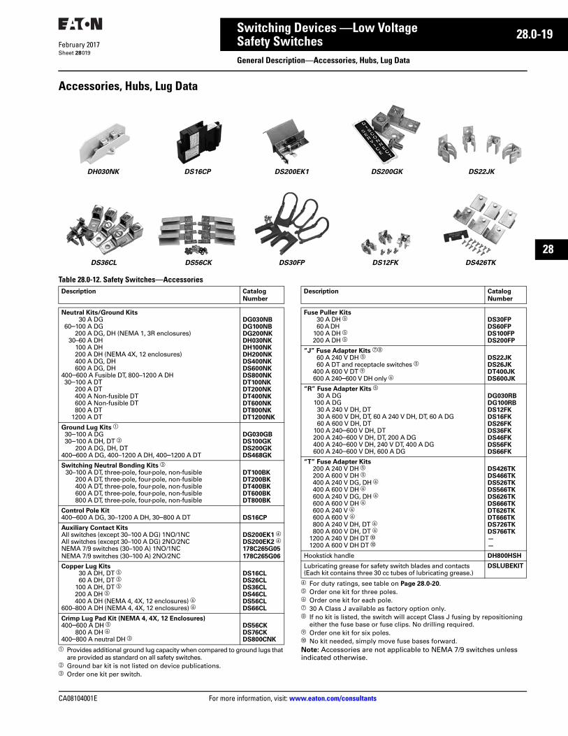
Accessories, Hubs, Lug Data
Table 28.0-12. Safety Switches—Accessories
a Provides additional ground lug capacity when compared to ground lugs that are provided as standard on all safety switches.
b Ground bar kit is not listed on device publications.c Order one kit per switch.
d For duty ratings, see table on Page 28.0-20. e Order one kit for three poles.f Order one kit for each pole.g 30 A Class J available as factory option only.h If no kit is listed, the switch will accept Class J fusing by repositioning
either the fuse base or fuse clips. No drilling required.i Order one kit for six poles.j No kit needed, simply move fuse bases forward.Note: Accessories are not applicable to NEMA 7/9 switches unless indicated otherwise.
DS200GKDH030NK DS16CP DS200EK1
DS36CL DS56CK DS30FP
DS22JK
DS12FK DS426TK
Description Catalog Number
Neutral Kits/Ground Kits30 A DG
60–100 A DG200 A DG, DH (NEMA 1, 3R enclosures)
30–60 A DH100 A DH200 A DH (NEMA 4X, 12 enclosures)400 A DG, DH600 A DG, DH
400–600 A Fusible DT, 800–1200 A DH30–100 A DT
200 A DT400 A Non-fusible DT600 A Non-fusible DT800 A DT
1200 A DT
DG030NBDG100NBDG200NKDH030NKDH100NKDH200NKDS400NKDS600NKDS800NKDT100NKDT200NKDT400NKDT600NKDT800NKDT1200NK
Ground Lug Kits a
30–100 A DG30–100 A DH, DT b
200 A DG, DH, DT400–600 A DG, 400–1200 A DH, 400–1200 A DT
DG030GBDS100GKDS200GKDS468GK
Switching Neutral Bonding Kits c
30–100 A DT, three-pole, four-pole, non-fusible200 A DT, three-pole, four-pole, non-fusible400 A DT, three-pole, four-pole, non-fusible600 A DT, three-pole, four-pole, non-fusible800 A DT, three-pole, four-pole, non-fusible
DT100BKDT200BKDT400BKDT600BKDT800BK
Control Pole Kit400–600 A DG, 30–1200 A DH, 30–800 A DT DS16CP
Auxiliary Contact KitsAll switches (except 30–100 A DG) 1NO/1NCAll switches (except 30–100 A DG) 2NO/2NCNEMA 7/9 switches (30–100 A) 1NO/1NCNEMA 7/9 switches (30–100 A) 2NO/2NC
DS200EK1 d
DS200EK2 d
178C265G05178C265G06
Copper Lug Kits30 A DH, DT e60 A DH, DT e
100 A DH, DT e200 A DH e400 A DH (NEMA 4, 4X, 12 enclosures) f
600–800 A DH (NEMA 4, 4X, 12 enclosures) f
DS16CLDS26CLDS36CLDS46CLDS56CLDS66CL
Crimp Lug Pad Kit (NEMA 4, 4X, 12 Enclosures)400–600 A DH e
800 A DH f400–800 A neutral DH c
DS56CKDS76CKDS800CNK
Description Catalog Number
Fuse Puller Kits30 A DH e60 A DH
100 A DH e200 A DH e
DS30FPDS60FPDS100FPDS200FP
“J” Fuse Adapter Kits gh
60 A 240 V DH e60 A DT and receptacle switches e
400 A 600 V DT i600 A 240–600 V DH only f
DS22JKDS26JKDT400JKDS600JK
“R” Fuse Adapter Kits e30 A DG
100 A DG30 A 240 V DH, DT30 A 600 V DH, DT, 60 A 240 V DH, DT, 60 A DG60 A 600 V DH, DT
100 A 240–600 V DH, DT200 A 240–600 V DH, DT, 200 A DG400 A 240–600 V DH, 240 V DT, 400 A DG600 A 240–600 V DH, 600 A DG
DG030RBDG100RBDS12FKDS16FKDS26FKDS36FKDS46FKDS56FKDS66FK
“T” Fuse Adapter Kits200 A 240 V DH e200 A 600 V DH e400 A 240 V DG, DH f400 A 600 V DH f600 A 240 V DG, DH f600 A 600 V DH f600 A 240 V f600 A 600 V f800 A 240 V DH, DT f800 A 600 V DH, DT f
1200 A 240 V DH DT j1200 A 600 V DH DT j
DS426TKDS466TKDS526TKDS566TKDS626TKDS666TKDT626TKDT666TKDS726TKDS766TK——
Hookstick handle DH800HSH
Lubricating grease for safety switch blades and contacts (Each kit contains three 30 cc tubes of lubricating grease.)
DSLUBEKIT
28.0-20
For more information, visit: www.eaton.com/consultants CA08104001E
February 2017
Switching Devices —Low Voltage
Sheet 28
22
23
24
25
26
27
28
29
30
31
32
33
34
35
36
37
38
39
40
41
42
43
Safety SwitchesGeneral Description—Accessories, Hubs, Lug Data
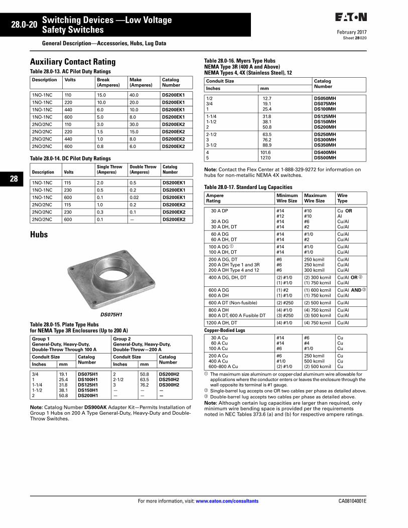
020
Auxiliary Contact RatingTable 28.0-13. AC Pilot Duty Ratings
Table 28.0-14. DC Pilot Duty Ratings
Hubs
DS075H1
Table 28.0-15. Plate Type Hubsfor NEMA Type 3R Enclosures (Up to 200 A)
Note: Catalog Number DS900AK Adapter Kit—Permits Installation of Group 1 Hubs on 200 A Type General-Duty, Heavy-Duty and Double-Throw Switches.
Table 28.0-16. Myers Type HubsNEMA Type 3R (400 A and Above)NEMA Types 4, 4X (Stainless Steel), 12
Note: Contact the Flex Center at 1-888-329-9272 for information on hubs for non-metallic NEMA 4X switches.
Table 28.0-17. Standard Lug Capacities
a The maximum size aluminum or copper-clad aluminum wire allowable for applications where the conductor enters or leaves the enclosure through the wall opposite its terminal is #1 gauge.
b Single-barrel lug accepts one OR two cables per phase as detailed above.c Double-barrel lug accepts two cables per phase as detailed above.Note: Although certain lug capacities are larger than required, only minimum wire bending space is provided per the requirements noted in NEC Tables 373.6 (a) and (b) for respective ampere ratings.
Description Volts Break (Amperes)
Make(Amperes)
Catalog Number
1NO-1NC 110 15.0 40.0 DS200EK1
1NO-1NC 220 10.0 20.0 DS200EK1
1NO-1NC 440 6.0 10.0 DS200EK1
1NO-1NC 600 5.0 8.0 DS200EK1
2NO/2NC 110 3.0 30.0 DS200EK2
2NO/2NC 220 1.5 15.0 DS200EK2
2NO/2NC 440 1.0 8.0 DS200EK2
2NO/2NC 600 0.8 6.0 DS200EK2
Description VoltsSingle Throw (Amperes)
Double Throw (Amperes)
Catalog Number
1NO-1NC 115 2.0 0.5 DS200EK1
1NO-1NC 230 0.5 0.2 DS200EK1
1NO-1NC 600 0.1 0.02 DS200EK1
2NO/2NC 115 1.0 0.2 DS200EK2
2NO/2NC 230 0.3 0.1 DS200EK2
2NO/2NC 600 0.1 — DS200EK2
Group 1General-Duty, Heavy-Duty, Double-Throw Through 100 A
Group 2General-Duty, Heavy-Duty, Double-Throw—200 A
Conduit Size CatalogNumber
Conduit Size CatalogNumberInches mm Inches mm
3/411-1/41-1/22
19.125.431.838.150.8
DS075H1DS100H1DS125H1DS150H1DS200H1
22-1/23——
50.863.576.2——
DS200H2DS250H2DS300H2——
Conduit Size Catalog NumberInches mm
1/23/41
12.719.125.4
DS050MHDS075MHDS100MH
1-1/41-1/22
31.838.150.8
DS125MHDS150MHDS200MH
2-1/233-1/2
63.576.288.9
DS250MHDS300MHDS350MH
45
101.6127.0
DS400MHDS500MH
AmpereRating
MinimumWire Size
MaximumWire Size
WireType
30 A DP
30 A DG30 A DH, DT
#14#12#14#14
#10#10#6#2
Cu ORAlCu/AlCu/Al
60 A DG60 A DH, DT
#14#14
#1/0#2
Cu/AlCu/Al
100 A DG a100 A DH, DT
#14#14
#1/0#1/0
Cu/AlCu/Al
200 A DG, DT200 A DH Type 1 and 3R200 A DH Type 4 and 12
#6#6#6
250 kcmil250 kcmil300 kcmil
Cu/AlCu/AlCu/Al
400 A DG, DH, DT (2) #1/0(1) #1/0
(2) 300 kcmil(1) 750 kcmil
Cu/Al OR b
Cu/Al
600 A DG600 A DH
(1) #2 (1) #1/0
(1) 600 kcmil(1) 750 kcmil
Cu/Al AND c
Cu/Al
600 A DT (Non-fusible) (2) #250 (2) 500 kcmil Cu/Al
800 A DH800 A DT, 600 A Fusible DT
(4) #1/0(3) #250
(4) 750 kcmil(3) 500 kcmil
Cu/AlCu/Al
1200 A DH, DT (4) #1/0 (4) 750 kcmil Cu/Al
Copper-Bodied Lugs30 A Cu60 A Cu
100 A Cu
#14#14#6
#6#4#1/0
CuCuCu
200 A Cu400 A Cu600–800 A Cu
#6#1/0(2) #1/0
250 kcmil500 kcmil(2) 500 kcmil
CuCuCu
CA08104001E For more information, visit: www.eaton.com/consultants
28.0-21February 2017
Switching Devices —Low Voltage
Sheet 28
22
23
24
25
26
27
28
29
30
31
32
33
34
35
36
37
38
39
40
41
42
43
Safety SwitchesGeneral Description—Lug Data, Connection Plugs
021
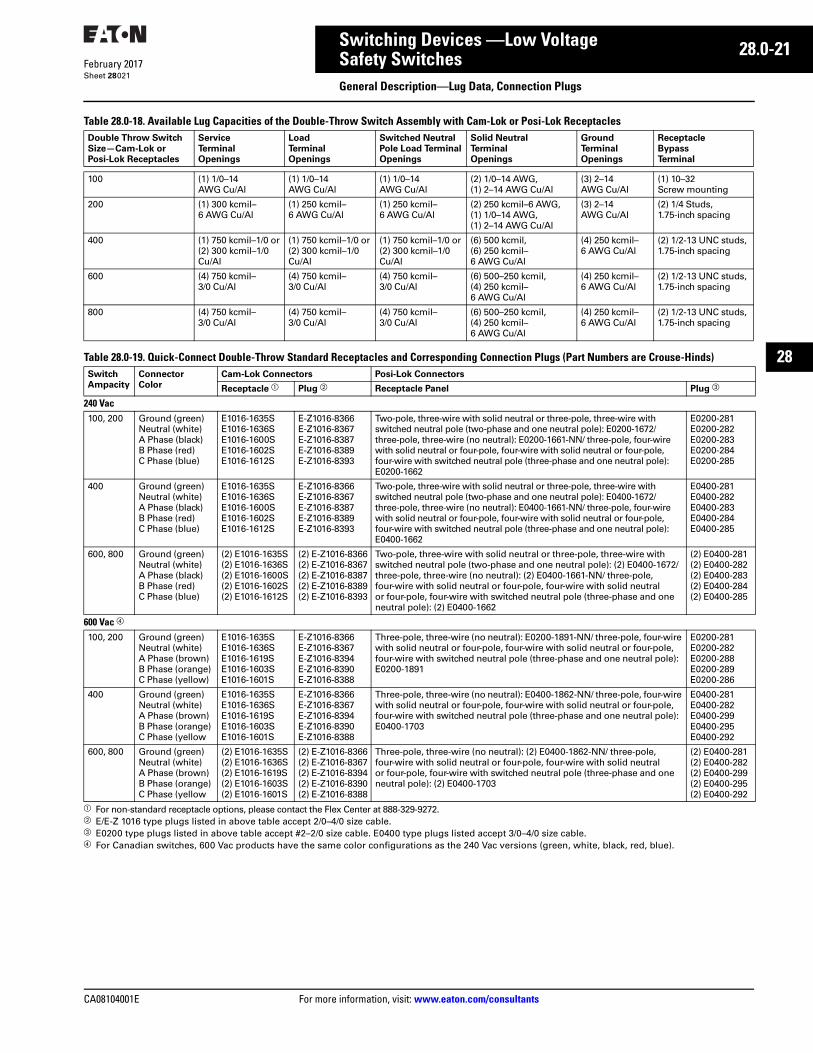
Table 28.0-18. Available Lug Capacities of the Double-Throw Switch Assembly with Cam-Lok or Posi-Lok Receptacles
Table 28.0-19. Quick-Connect Double-Throw Standard Receptacles and Corresponding Connection Plugs (Part Numbers are Crouse-Hinds)
a For non-standard receptacle options, please contact the Flex Center at 888-329-9272.b E/E-Z 1016 type plugs listed in above table accept 2/0–4/0 size cable.c E0200 type plugs listed in above table accept #2–2/0 size cable. E0400 type plugs listed accept 3/0–4/0 size cable.d For Canadian switches, 600 Vac products have the same color configurations as the 240 Vac versions (green, white, black, red, blue).
Double Throw SwitchSize—Cam-Lok orPosi-Lok Receptacles
Service Terminal Openings
Load Terminal Openings
Switched Neutral Pole Load Terminal Openings
Solid Neutral Terminal Openings
Ground Terminal Openings
Receptacle Bypass Terminal
100 (1) 1/0–14AWG Cu/Al
(1) 1/0–14AWG Cu/Al
(1) 1/0–14AWG Cu/Al
(2) 1/0–14 AWG,(1) 2–14 AWG Cu/Al
(3) 2–14AWG Cu/Al
(1) 10–32Screw mounting
200 (1) 300 kcmil–6 AWG Cu/Al
(1) 250 kcmil–6 AWG Cu/Al
(1) 250 kcmil–6 AWG Cu/Al
(2) 250 kcmil–6 AWG,(1) 1/0–14 AWG,(1) 2–14 AWG Cu/Al
(3) 2–14AWG Cu/Al
(2) 1/4 Studs,1.75-inch spacing
400 (1) 750 kcmil–1/0 or(2) 300 kcmil–1/0 Cu/Al
(1) 750 kcmil–1/0 or(2) 300 kcmil–1/0 Cu/Al
(1) 750 kcmil–1/0 or(2) 300 kcmil–1/0 Cu/Al
(6) 500 kcmil,(6) 250 kcmil–6 AWG Cu/Al
(4) 250 kcmil–6 AWG Cu/Al
(2) 1/2-13 UNC studs, 1.75-inch spacing
600 (4) 750 kcmil–3/0 Cu/Al
(4) 750 kcmil–3/0 Cu/Al
(4) 750 kcmil–3/0 Cu/Al
(6) 500–250 kcmil,(4) 250 kcmil–6 AWG Cu/Al
(4) 250 kcmil–6 AWG Cu/Al
(2) 1/2-13 UNC studs, 1.75-inch spacing
800 (4) 750 kcmil–3/0 Cu/Al
(4) 750 kcmil–3/0 Cu/Al
(4) 750 kcmil–3/0 Cu/Al
(6) 500–250 kcmil,(4) 250 kcmil–6 AWG Cu/Al
(4) 250 kcmil–6 AWG Cu/Al
(2) 1/2-13 UNC studs, 1.75-inch spacing
Switch Ampacity
Connector Color
Cam-Lok Connectors Posi-Lok Connectors
Receptacle a Plug b Receptacle Panel Plug c
240 Vac100, 200 Ground (green)
Neutral (white)A Phase (black)B Phase (red)C Phase (blue)
E1016-1635SE1016-1636SE1016-1600SE1016-1602SE1016-1612S
E-Z1016-8366E-Z1016-8367E-Z1016-8387E-Z1016-8389E-Z1016-8393
Two-pole, three-wire with solid neutral or three-pole, three-wire with switched neutral pole (two-phase and one neutral pole): E0200-1672/ three-pole, three-wire (no neutral): E0200-1661-NN/ three-pole, four-wire with solid neutral or four-pole, four-wire with solid neutral or four-pole, four-wire with switched neutral pole (three-phase and one neutral pole): E0200-1662
E0200-281E0200-282E0200-283E0200-284E0200-285
400 Ground (green)Neutral (white)A Phase (black)B Phase (red)C Phase (blue)
E1016-1635SE1016-1636SE1016-1600SE1016-1602SE1016-1612S
E-Z1016-8366E-Z1016-8367E-Z1016-8387E-Z1016-8389E-Z1016-8393
Two-pole, three-wire with solid neutral or three-pole, three-wire with switched neutral pole (two-phase and one neutral pole): E0400-1672/ three-pole, three-wire (no neutral): E0400-1661-NN/ three-pole, four-wire with solid neutral or four-pole, four-wire with solid neutral or four-pole, four-wire with switched neutral pole (three-phase and one neutral pole): E0400-1662
E0400-281E0400-282E0400-283E0400-284E0400-285
600, 800 Ground (green)Neutral (white)A Phase (black)B Phase (red)C Phase (blue)
(2) E1016-1635S(2) E1016-1636S(2) E1016-1600S(2) E1016-1602S(2) E1016-1612S
(2) E-Z1016-8366(2) E-Z1016-8367(2) E-Z1016-8387(2) E-Z1016-8389(2) E-Z1016-8393
Two-pole, three-wire with solid neutral or three-pole, three-wire with switched neutral pole (two-phase and one neutral pole): (2) E0400-1672/ three-pole, three-wire (no neutral): (2) E0400-1661-NN/ three-pole, four-wire with solid neutral or four-pole, four-wire with solid neutral or four-pole, four-wire with switched neutral pole (three-phase and one neutral pole): (2) E0400-1662
(2) E0400-281(2) E0400-282(2) E0400-283(2) E0400-284(2) E0400-285
600 Vac d
100, 200 Ground (green)Neutral (white)A Phase (brown)B Phase (orange)C Phase (yellow)
E1016-1635SE1016-1636SE1016-1619SE1016-1603SE1016-1601S
E-Z1016-8366E-Z1016-8367E-Z1016-8394E-Z1016-8390E-Z1016-8388
Three-pole, three-wire (no neutral): E0200-1891-NN/ three-pole, four-wire with solid neutral or four-pole, four-wire with solid neutral or four-pole, four-wire with switched neutral pole (three-phase and one neutral pole): E0200-1891
E0200-281E0200-282E0200-288E0200-289E0200-286
400 Ground (green)Neutral (white)A Phase (brown)B Phase (orange)C Phase (yellow
E1016-1635SE1016-1636SE1016-1619SE1016-1603SE1016-1601S
E-Z1016-8366E-Z1016-8367E-Z1016-8394E-Z1016-8390E-Z1016-8388
Three-pole, three-wire (no neutral): E0400-1862-NN/ three-pole, four-wire with solid neutral or four-pole, four-wire with solid neutral or four-pole, four-wire with switched neutral pole (three-phase and one neutral pole): E0400-1703
E0400-281E0400-282E0400-299E0400-295E0400-292
600, 800 Ground (green)Neutral (white)A Phase (brown)B Phase (orange)C Phase (yellow
(2) E1016-1635S(2) E1016-1636S(2) E1016-1619S(2) E1016-1603S(2) E1016-1601S
(2) E-Z1016-8366(2) E-Z1016-8367(2) E-Z1016-8394(2) E-Z1016-8390(2) E-Z1016-8388
Three-pole, three-wire (no neutral): (2) E0400-1862-NN/ three-pole, four-wire with solid neutral or four-pole, four-wire with solid neutral or four-pole, four-wire with switched neutral pole (three-phase and one neutral pole): (2) E0400-1703
(2) E0400-281(2) E0400-282(2) E0400-299(2) E0400-295(2) E0400-292
28.0-22
For more information, visit: www.eaton.com/consultants CA08104001E
February 2017
Switching Devices —Low Voltage
Sheet 28
22
23
24
25
26
27
28
29
30
31
32
33
34
35
36
37
38
39
40
41
42
43
Safety SwitchesGeneral Description—Lug Data, Connection Plugs
022
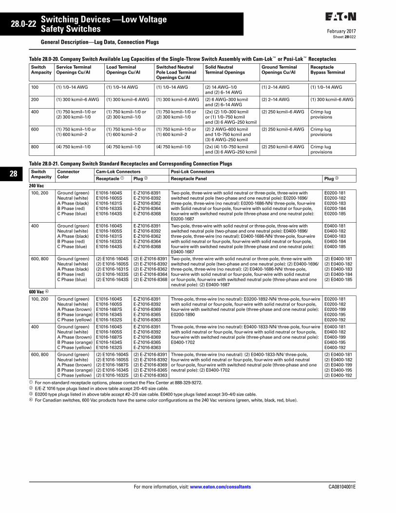
Table 28.0-20. Company Switch Available Lug Capacities of the Single-Throw Switch Assembly with Cam-Lok™ or Posi-Lok™ Receptacles
Table 28.0-21. Company Switch Standard Receptacles and Corresponding Connection Plugs
a For non-standard receptacle options, please contact the Flex Center at 888-329-9272.b E/E-Z 1016 type plugs listed in above table accept 2/0–4/0 size cable.c E0200 type plugs listed in above table accept #2–2/0 size cable. E0400 type plugs listed accept 3/0–4/0 size cable.d For Canadian switches, 600 Vac products have the same color configurations as the 240 Vac versions (green, white, black, red, blue).
Switch Ampacity
Service Terminal Openings Cu/AI
Load Terminal Openings Cu/AI
Switched Neutral Pole Load Terminal Openings Cu/AI
Solid Neutral Terminal Openings
Ground Terminal Openings Cu/AI
Receptacle Bypass Terminal
100 (1) 1/0–14 AWG (1) 1/0–14 AWG (1) 1/0–14 AWG (2) 14 AWG–1/0 and (2) 6–14 AWG
(1) 2–14 AWG (1) 1/0–14 AWG
200 (1) 300 kcmil–6 AWG (1) 300 kcmil–6 AWG (1) 300 kcmil–6 AWG (2) 6 AWG–300 kcmil and (2) 6–14 AWG
(2) 2–14 AWG (1) 300 kcmil–6 AWG
400 (1) 750 kcmil–1/0 or (2) 300 kcmil–1/0
(1) 750 kcmil–1/0 or (2) 300 kcmil–1/0
(1) 750 kcmil–1/0 or (2) 300 kcmil–1/0
(2x) (2) 1/0–300 kcmil or (1) 1/0–750 kcmil and (3) 6 AWG–250 kcmil
(2) 250 kcmil–6 AWG Crimp lug provisions
600 (1) 750 kcmil–1/0 or (1) 600 kcmil–2
(1) 750 kcmil–1/0 or (1) 600 kcmil–2
(1) 750 kcmil–1/0 or (1) 600 kcmil–2
(2) 2 AWG–600 kcmil and 1/0–750 kcmil and (3) 6 AWG–250 kcmil
(2) 250 kcmil–6 AWG Crimp lug provisions
800 (4) 750 kcmil–1/0 (4) 750 kcmil–1/0 (4) 750 kcmil–1/0 (2x) (4) 1/0–750 kcmil and (3) 6 AWG–250 kcmil
(2) 250 kcmil–6 AWG Crimp lug provisions
Switch Ampacity
Connector Color
Cam-Lok Connectors Posi-Lok Connectors
Receptacle a Plug b Receptacle Panel Plug c
240 Vac100, 200 Ground (green)
Neutral (white)A Phase (black)B Phase (red)C Phase (blue)
E1016-1604SE1016-1605SE1016-1631SE1016-1633SE1016-1643S
E-Z1016-8391E-Z1016-8392E-Z1016-8362E-Z1016-8364E-Z1016-8368
Two-pole, three-wire with solid neutral or three-pole, three-wire with switched neutral pole (two-phase and one neutral pole): E0200-1696/ three-pole, three-wire (no neutral): E0200-1686-NN/ three-pole, four-wire with Solid neutral or four-pole, four-wire with solid neutral or four-pole, four-wire with switched neutral pole (three-phase and one neutral pole): E0200-1687
E0200-181E0200-182E0200-183E0200-184E0200-185
400 Ground (green)Neutral (white)A Phase (black)B Phase (red)C Phase (blue)
E1016-1604SE1016-1605SE1016-1631SE1016-1633SE1016-1643S
E-Z1016-8391E-Z1016-8392E-Z1016-8362E-Z1016-8364E-Z1016-8368
Two-pole, three-wire with solid neutral or three-pole, three-wire with switched neutral pole (two-phase and one neutral pole): E0400-1696/ three-pole, three-wire (no neutral): E0400-1686-NN/ three-pole, four-wire with solid neutral or four-pole, four-wire with solid neutral or four-pole, four-wire with switched neutral pole (three-phase and one neutral pole): E0400-1687
E0400-181E0400-182E0400-183E0400-184E0400-185
600, 800 Ground (green)Neutral (white)A Phase (black)B Phase (red)C Phase (blue)
(2) E1016-1604S(2) E1016-1605S(2) E1016-1631S(2) E1016-1633S(2) E1016-1643S
(2) E-Z1016-8391(2) E-Z1016-8392(2) E-Z1016-8362(2) E-Z1016-8364(2) E-Z1016-8368
Two-pole, three-wire with solid neutral or three-pole, three-wire with switched neutral pole (two-phase and one neutral pole): (2) E0400-1696/ three-pole, three-wire (no neutral): (2) E0400-1686-NN/ three-pole, four-wire with solid neutral or four-pole, four-wire with solid neutral or four-pole, four-wire with switched neutral pole (three-phase and one neutral pole): (2) E0400-1687
(2) E0400-181(2) E0400-182(2) E0400-183(2) E0400-184(2) E0400-185
600 Vac d
100, 200 Ground (green)Neutral (white)A Phase (brown)B Phase (orange)C Phase (yellow)
E1016-1604SE1016-1605SE1016-1687SE1016-1634SE1016-1632S
E-Z1016-8391E-Z1016-8392E-Z1016-8369E-Z1016-8365E-Z1016-8363
Three-pole, three-wire (no neutral): E0200-1892-NN/ three-pole, four-wire with solid neutral or four-pole, four-wire with solid neutral or four-pole, four-wire with switched neutral pole (three-phase and one neutral pole): E0200-1890
E0200-181E0200-182E0200-199E0200-195E0200-192
400 Ground (green)Neutral (white)A Phase (brown)B Phase (orange)C Phase (yellow)
E1016-1604SE1016-1605SE1016-1687SE1016-1634SE1016-1632S
E-Z1016-8391E-Z1016-8392E-Z1016-8369E-Z1016-8365E-Z1016-8363
Three-pole, three-wire (no neutral): E0400-1833-NN/ three-pole, four-wire with solid neutral or four-pole, four-wire with solid neutral or four-pole, four-wire with switched neutral pole (three-phase and one neutral pole): E0400-1702
E0400-181E0400-182E0400-199E0400-195E0400-192
600, 800 Ground (green)Neutral (white)A Phase (brown)B Phase (orange)C Phase (yellow)
(2) E1016-1604S(2) E1016-1605S(2) E1016-1687S(2) E1016-1634S(2) E1016-1632S
(2) E-Z1016-8391(2) E-Z1016-8392(2) E-Z1016-8369(2) E-Z1016-8365(2) E-Z1016-8363
Three-pole, three-wire (no neutral): (2) E0400-1833-NN/ three-pole, four-wire with solid neutral or four-pole, four-wire with solid neutral or four-pole, four-wire with switched neutral pole (three-phase and one neutral pole): (2) E0400-1702
(2) E0400-181(2) E0400-182(2) E0400-199(2) E0400-195(2) E0400-192
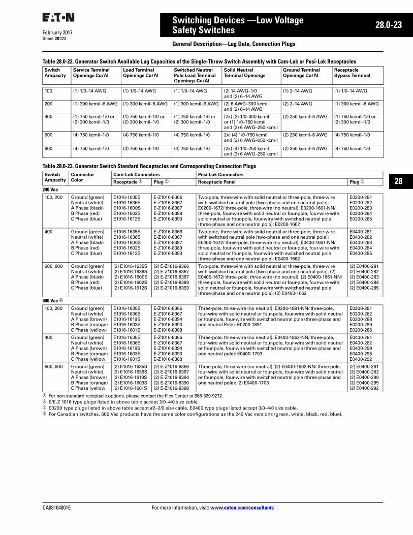
CA08104001E For more information, visit: www.eaton.com/consultants
28.0-23February 2017
Switching Devices —Low Voltage
Sheet 28
22
23
24
25
26
27
28
29
30
31
32
33
34
35
36
37
38
39
40
41
42
43
Safety SwitchesGeneral Description—Lug Data, Connection Plugs
023
Table 28.0-22. Generator Switch Available Lug Capacities of the Single-Throw Switch Assembly with Cam-Lok or Posi-Lok Receptacles
Table 28.0-23. Generator Switch Standard Receptacles and Corresponding Connection Plugs
a For non-standard receptacle options, please contact the Flex Center at 888-329-9272.b E/E-Z 1016 type plugs listed in above table accept 2/0–4/0 size cable.c E0200 type plugs listed in above table accept #2–2/0 size cable. E0400 type plugs listed accept 3/0–4/0 size cable.d For Canadian switches, 600 Vac products have the same color configurations as the 240 Vac versions (green, white, black, red, blue).
Switch Ampacity
Service Terminal Openings Cu/AI
Load Terminal Openings Cu/AI
Switched Neutral Pole Load Terminal Openings Cu/AI
Solid Neutral Terminal Openings
Ground Terminal Openings Cu/AI
Receptacle Bypass Terminal
100 (1) 1/0–14 AWG (1) 1/0–14 AWG (1) 1/0–14 AWG (2) 14 AWG–1/0 and (2) 6–14 AWG
(1) 2–14 AWG (1) 1/0–14 AWG
200 (1) 300 kcmil–6 AWG (1) 300 kcmil–6 AWG (1) 300 kcmil–6 AWG (2) 6 AWG–300 kcmil and (2) 6–14 AWG
(2) 2–14 AWG (1) 300 kcmil–6 AWG
400 (1) 750 kcmil–1/0 or (2) 300 kcmil–1/0
(1) 750 kcmil–1/0 or (2) 300 kcmil–1/0
(1) 750 kcmil–1/0 or (2) 300 kcmil–1/0
(2x) (2) 1/0–300 kcmil or (1) 1/0–750 kcmil and (3) 6 AWG–250 kcmil
(2) 250 kcmil–6 AWG (1) 750 kcmil–1/0 or (2) 300 kcmil–1/0
600 (4) 750 kcmil–1/0 (4) 750 kcmil–1/0 (4) 750 kcmil–1/0 2x) (4) 1/0–750 kcmil and (3) 6 AWG–250 kcmil
(2) 250 kcmil–6 AWG (4) 750 kcmil–1/0
800 (4) 750 kcmil–1/0 (4) 750 kcmil–1/0 (4) 750 kcmil–1/0 (2x) (4) 1/0–750 kcmil and (3) 6 AWG–250 kcmil
(2) 250 kcmil–6 AWG (4) 750 kcmil–1/0
Switch Ampacity
Connector Color
Cam-Lok Connectors Posi-Lok Connectors
Receptacle a Plug b Receptacle Panel Plug c
240 Vac100, 200 Ground (green)
Neutral (white)A Phase (black)B Phase (red)C Phase (blue)
E1016-1635SE1016-1636SE1016-1600SE1016-1602SE1016-1612S
E-Z1016-8366E-Z1016-8367E-Z1016-8387E-Z1016-8389E-Z1016-8393
Two-pole, three-wire with solid neutral or three-pole, three-wire with switched neutral pole (two-phase and one neutral pole): E0200-1672/ three-pole, three-wire (no neutral): E0200-1661-NN/ three-pole, four-wire with solid neutral or four-pole, four-wire with solid neutral or four-pole, four-wire with switched neutral pole (three-phase and one neutral pole): E0200-1662
E0200-281E0200-282E0200-283E0200-284E0200-285
400 Ground (green)Neutral (white)A Phase (black)B Phase (red)C Phase (blue)
E1016-1635SE1016-1636SE1016-1600SE1016-1602SE1016-1612S
E-Z1016-8366E-Z1016-8367E-Z1016-8387E-Z1016-8389E-Z1016-8393
Two-pole, three-wire with solid neutral or three-pole, three-wire with switched neutral pole (two-phase and one neutral pole): E0400-1672/ three-pole, three-wire (no neutral): E0400-1661-NN/ three-pole, four-wire with solid neutral or four-pole, four-wire with solid neutral or four-pole, four-wire with switched neutral pole (three-phase and one neutral pole): E0400-1662
E0400-281E0400-282E0400-283E0400-284E0400-285
600, 800 Ground (green)Neutral (white)A Phase (black)B Phase (red)C Phase (blue)
(2) E1016-1635S(2) E1016-1636S(2) E1016-1600S(2) E1016-1602S(2) E1016-1612S
(2) E-Z1016-8366(2) E-Z1016-8367(2) E-Z1016-8387(2) E-Z1016-8389(2) E-Z1016-8393
Two-pole, three-wire with solid neutral or three-pole, three-wire with switched neutral pole (two-phase and one neutral pole): (2) E0400-1672/ three-pole, three-wire (no neutral): (2) E0400-1661-NN/ three-pole, four-wire with solid neutral or four-pole, four-wire with solid neutral or four-pole, four-wire with switched neutral pole (three-phase and one neutral pole): (2) E0400-1662
(2) E0400-281(2) E0400-282(2) E0400-283(2) E0400-284(2) E0400-285
600 Vac d
100, 200 Ground (green)Neutral (white)A Phase (brown)B Phase (orange)C Phase (yellow)
E1016-1635SE1016-1636SE1016-1619SE1016-1603SE1016-1601S
E-Z1016-8366E-Z1016-8367E-Z1016-8394E-Z1016-8390E-Z1016-8388
Three-pole, three-wire (no neutral): E0200-1891-NN/ three-pole, four-wire with solid neutral or four-pole, four-wire with solid neutral or four-pole, four-wire with switched neutral pole (three-phase and one neutral Pole): E0200-1891
E0200-281E0200-282E0200-288E0200-289E0200-286
400 Ground (green)Neutral (white)A Phase (brown)B Phase (orange)C Phase (yellow
E1016-1635SE1016-1636SE1016-1619SE1016-1603SE1016-1601S
E-Z1016-8366E-Z1016-8367E-Z1016-8394E-Z1016-8390E-Z1016-8388
Three-pole, three-wire (no neutral): E0400-1862-NN/ three-pole, four-wire with solid neutral or four-pole, four-wire with solid neutral or four-pole, four-wire with switched neutral pole (three-phase and one neutral pole): E0400-1703
E0400-281E0400-282E0400-299E0400-295E0400-292
600, 800 Ground (green)Neutral (white)A Phase (brown)B Phase (orange)C Phase (yellow
(2) E1016-1635S(2) E1016-1636S(2) E1016-1619S(2) E1016-1603S(2) E1016-1601S
(2) E-Z1016-8366(2) E-Z1016-8367(2) E-Z1016-8394(2) E-Z1016-8390(2) E-Z1016-8388
Three-pole, three-wire (no neutral): (2) E0400-1862-NN/ three-pole, four-wire with solid neutral or four-pole, four-wire with solid neutral or four-pole, four-wire with switched neutral pole (three-phase and one neutral pole): (2) E0400-1703
(2) E0400-281(2) E0400-282(2) E0400-299(2) E0400-295(2) E0400-292
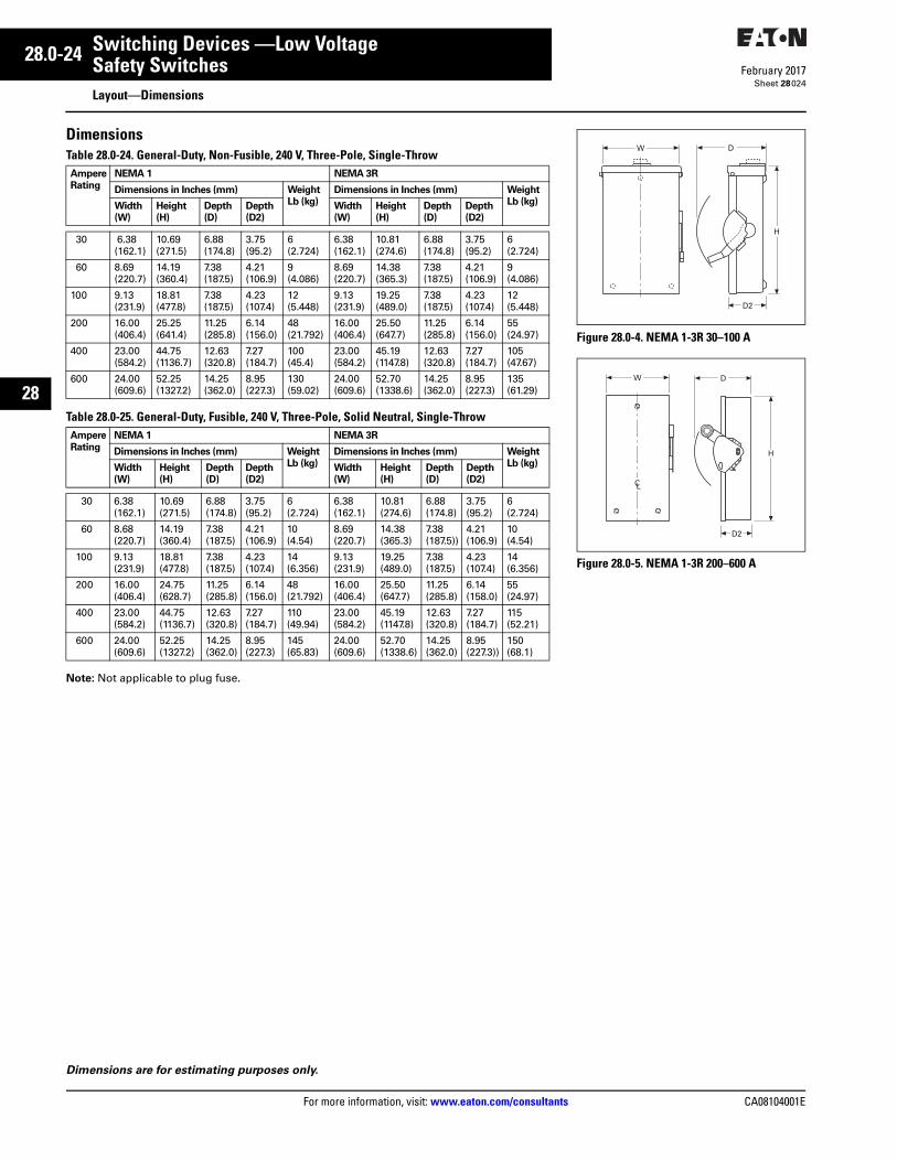
28.0-24
For more information, visit: www.eaton.com/consultants CA08104001E
February 2017
Switching Devices —Low Voltage
Sheet 28
22
23
24
25
26
27
28
29
30
31
32
33
34
35
36
37
38
39
40
41
42
43
Safety SwitchesLayout—Dimensions
024
DimensionsTable 28.0-24. General-Duty, Non-Fusible, 240 V, Three-Pole, Single-Throw
Table 28.0-25. General-Duty, Fusible, 240 V, Three-Pole, Solid Neutral, Single-Throw
Note: Not applicable to plug fuse.
AmpereRating
NEMA 1 NEMA 3R
Dimensions in Inches (mm) WeightLb (kg)
Dimensions in Inches (mm) WeightLb (kg)Width
(W)Height (H)
Depth (D)
Depth (D2)
Width (W)
Height (H)
Depth (D)
Depth (D2)
30 6.38(162.1)
10.69(271.5)
6.88(174.8)
3.75(95.2)
6(2.724)
6.38(162.1)
10.81(274.6)
6.88(174.8)
3.75(95.2)
6(2.724)
60 8.69(220.7)
14.19(360.4)
7.38(187.5)
4.21(106.9)
9(4.086)
8.69(220.7)
14.38(365.3)
7.38(187.5)
4.21(106.9)
9(4.086)
100 9.13(231.9)
18.81(477.8)
7.38(187.5)
4.23(107.4)
12(5.448)
9.13(231.9)
19.25(489.0)
7.38(187.5)
4.23(107.4)
12(5.448)
200 16.00(406.4)
25.25(641.4)
11.25(285.8)
6.14(156.0)
48(21.792)
16.00(406.4)
25.50(647.7)
11.25(285.8)
6.14(156.0)
55(24.97)
400 23.00(584.2)
44.75(1136.7)
12.63(320.8)
7.27(184.7)
100(45.4)
23.00(584.2)
45.19(1147.8)
12.63(320.8)
7.27(184.7)
105(47.67)
600 24.00(609.6)
52.25(1327.2)
14.25(362.0)
8.95(227.3)
130(59.02)
24.00(609.6)
52.70(1338.6)
14.25(362.0)
8.95(227.3)
135(61.29)
AmpereRating
NEMA 1 NEMA 3R
Dimensions in Inches (mm) WeightLb (kg)
Dimensions in Inches (mm) WeightLb (kg)Width
(W)Height (H)
Depth (D)
Depth (D2)
Width (W)
Height (H)
Depth (D)
Depth (D2)
30 6.38(162.1)
10.69 (271.5)
6.88 (174.8)
3.75 (95.2)
6 (2.724)
6.38 (162.1)
10.81 (274.6)
6.88 (174.8)
3.75 (95.2)
6 (2.724)
60 8.68(220.7)
14.19 (360.4)
7.38 (187.5)
4.21 (106.9)
10 (4.54)
8.69 (220.7)
14.38 (365.3)
7.38 (187.5))
4.21 (106.9)
10 (4.54)
100 9.13(231.9)
18.81 (477.8)
7.38 (187.5)
4.23 (107.4)
14 (6.356)
9.13 (231.9)
19.25 (489.0)
7.38 (187.5)
4.23 (107.4)
14 (6.356)
200 16.00(406.4)
24.75 (628.7)
11.25(285.8)
6.14(156.0)
48 (21.792)
16.00(406.4)
25.50 (647.7)
11.25 (285.8)
6.14 (158.0)
55 (24.97)
400 23.00(584.2)
44.75 (1136.7)
12.63(320.8)
7.27(184.7)
110 (49.94)
23.00(584.2)
45.19 (1147.8)
12.63(320.8)
7.27 (184.7)
115 (52.21)
600 24.00(609.6)
52.25 (1327.2)
14.25(362.0)
8.95(227.3)
145 (65.83)
24.00(609.6)
52.70 (1338.6)
14.25(362.0)
8.95 (227.3))
150 (68.1)
Dimensions are for estimating purposes only.
Figure 28.0-4. NEMA 1-3R 30–100 A
Figure 28.0-5. NEMA 1-3R 200–600 A
H
W D
D2
W
H
CL
D2
D
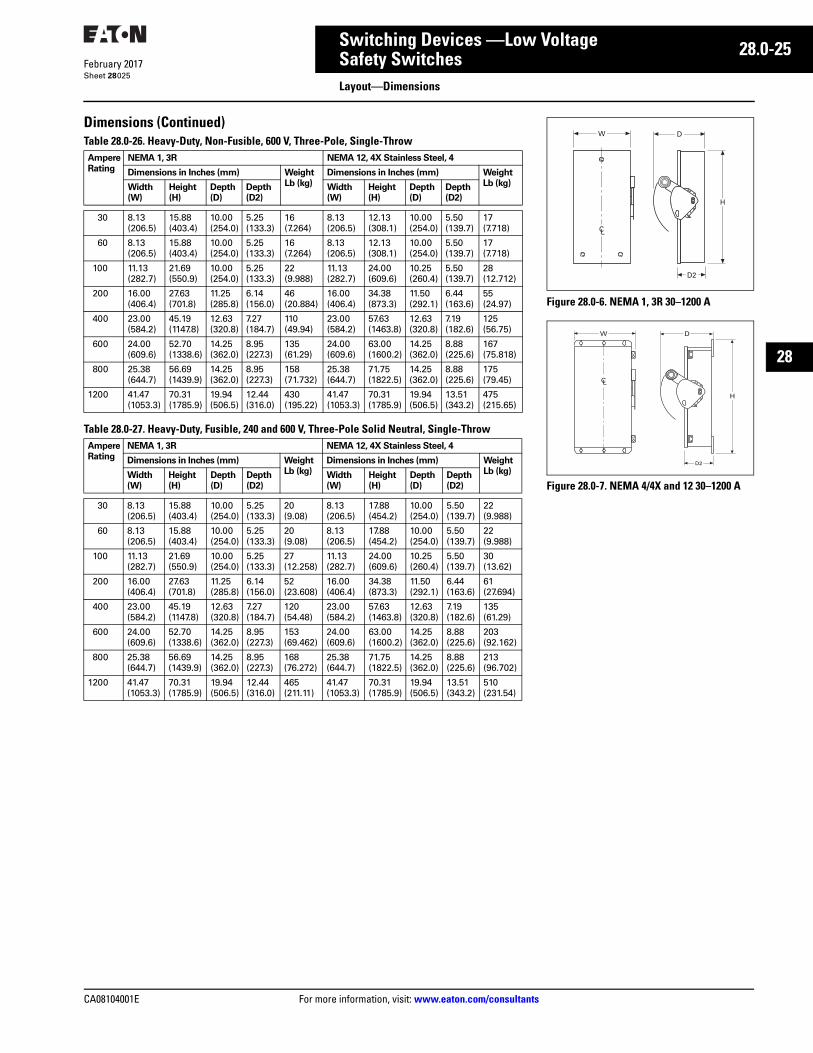
CA08104001E For more information, visit: www.eaton.com/consultants
28.0-25February 2017
Switching Devices —Low Voltage
Sheet 28
22
23
24
25
26
27
28
29
30
31
32
33
34
35
36
37
38
39
40
41
42
43
Safety SwitchesLayout—Dimensions
025
Dimensions (Continued)Table 28.0-26. Heavy-Duty, Non-Fusible, 600 V, Three-Pole, Single-Throw
Table 28.0-27. Heavy-Duty, Fusible, 240 and 600 V, Three-Pole Solid Neutral, Single-Throw
AmpereRating
NEMA 1, 3R NEMA 12, 4X Stainless Steel, 4
Dimensions in Inches (mm) WeightLb (kg)
Dimensions in Inches (mm) WeightLb (kg)Width
(W)Height (H)
Depth (D)
Depth (D2)
Width (W)
Height (H)
Depth (D)
Depth (D2)
30 8.13(206.5)
15.88(403.4)
10.00 (254.0)
5.25(133.3)
16(7.264)
8.13(206.5)
12.13(308.1)
10.00(254.0)
5.50(139.7)
17(7.718)
60 8.13(206.5)
15.88(403.4)
10.00(254.0)
5.25(133.3)
16(7.264)
8.13(206.5)
12.13(308.1)
10.00(254.0)
5.50(139.7)
17(7.718)
100 11.13(282.7)
21.69(550.9)
10.00(254.0)
5.25(133.3)
22(9.988)
11.13(282.7)
24.00(609.6)
10.25(260.4)
5.50(139.7)
28(12.712)
200 16.00(406.4)
27.63(701.8)
11.25(285.8)
6.14(156.0)
46(20.884)
16.00(406.4)
34.38(873.3)
11.50(292.1)
6.44(163.6)
55(24.97)
400 23.00(584.2)
45.19(1147.8)
12.63(320.8)
7.27(184.7)
110(49.94)
23.00(584.2)
57.63(1463.8)
12.63(320.8)
7.19(182.6)
125(56.75)
600 24.00(609.6)
52.70(1338.6)
14.25(362.0)
8.95(227.3)
135(61.29)
24.00(609.6)
63.00(1600.2)
14.25(362.0)
8.88(225.6)
167(75.818)
800 25.38(644.7)
56.69(1439.9)
14.25(362.0)
8.95(227.3)
158(71.732)
25.38(644.7)
71.75(1822.5)
14.25(362.0)
8.88(225.6)
175(79.45)
1200 41.47(1053.3)
70.31(1785.9)
19.94(506.5)
12.44(316.0)
430(195.22)
41.47(1053.3)
70.31(1785.9)
19.94(506.5)
13.51(343.2)
475(215.65)
AmpereRating
NEMA 1, 3R NEMA 12, 4X Stainless Steel, 4
Dimensions in Inches (mm) WeightLb (kg)
Dimensions in Inches (mm) WeightLb (kg)Width
(W)Height (H)
Depth (D)
Depth (D2)
Width (W)
Height (H)
Depth (D)
Depth (D2)
30 8.13(206.5)
15.88(403.4)
10.00(254.0)
5.25(133.3)
20(9.08)
8.13(206.5)
17.88(454.2)
10.00(254.0)
5.50(139.7)
22(9.988)
60 8.13(206.5)
15.88(403.4)
10.00(254.0)
5.25(133.3)
20(9.08)
8.13(206.5)
17.88(454.2)
10.00(254.0)
5.50(139.7)
22(9.988)
100 11.13(282.7)
21.69(550.9)
10.00(254.0)
5.25(133.3)
27(12.258)
11.13(282.7)
24.00(609.6)
10.25(260.4)
5.50(139.7)
30(13.62)
200 16.00(406.4)
27.63(701.8)
11.25(285.8)
6.14(156.0)
52(23.608)
16.00(406.4)
34.38(873.3)
11.50(292.1)
6.44(163.6)
61(27.694)
400 23.00(584.2)
45.19(1147.8)
12.63(320.8)
7.27(184.7)
120(54.48)
23.00(584.2)
57.63(1463.8)
12.63(320.8)
7.19(182.6)
135(61.29)
600 24.00(609.6)
52.70(1338.6)
14.25(362.0)
8.95(227.3)
153(69.462)
24.00(609.6)
63.00(1600.2)
14.25(362.0)
8.88(225.6)
203(92.162)
800 25.38(644.7)
56.69(1439.9)
14.25(362.0)
8.95(227.3)
168(76.272)
25.38(644.7)
71.75(1822.5)
14.25(362.0)
8.88(225.6)
213(96.702)
1200 41.47(1053.3)
70.31(1785.9)
19.94(506.5)
12.44(316.0)
465(211.11)
41.47(1053.3)
70.31(1785.9)
19.94(506.5)
13.51(343.2)
510(231.54)
Figure 28.0-6. NEMA 1, 3R 30–1200 A
Figure 28.0-7. NEMA 4/4X and 12 30–1200 A
W
H
CL
D2
D
DW
CL
H
D2
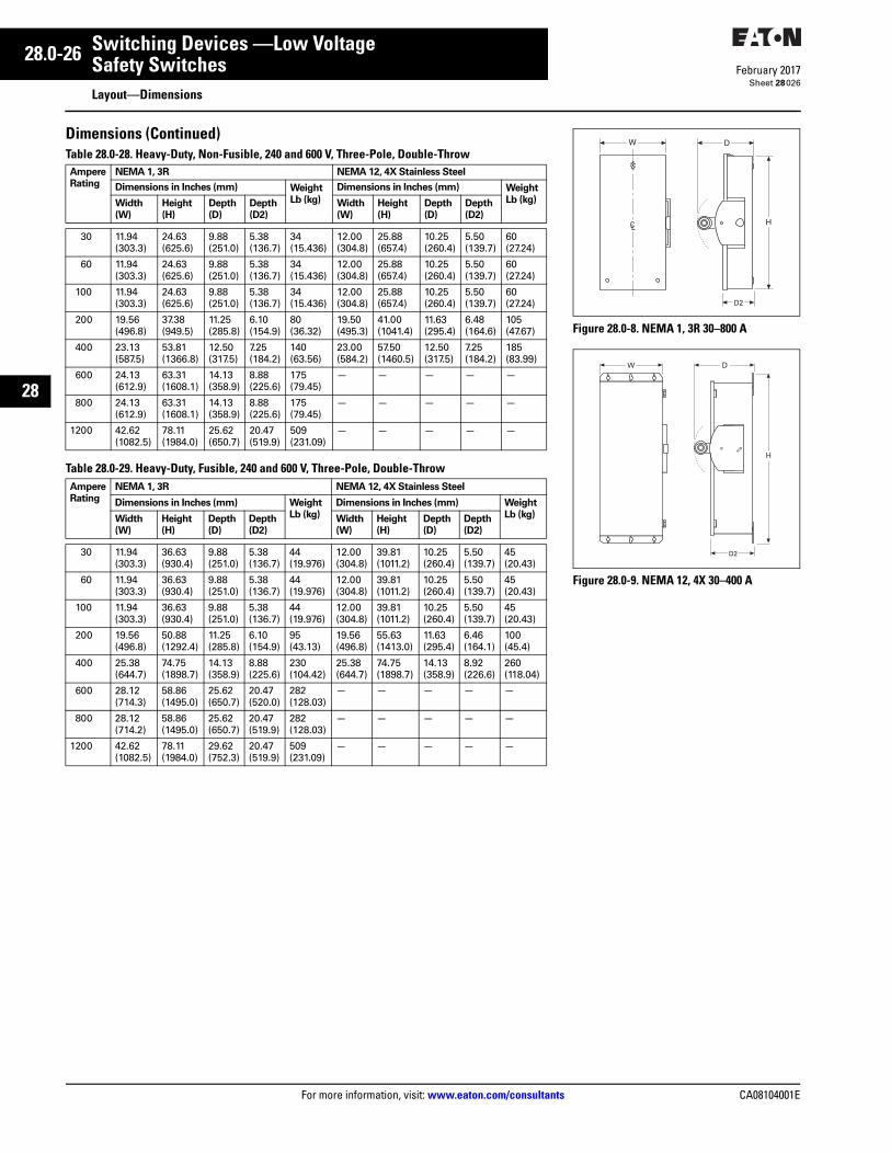
28.0-26
For more information, visit: www.eaton.com/consultants CA08104001E
February 2017
Switching Devices —Low Voltage
Sheet 28
22
23
24
25
26
27
28
29
30
31
32
33
34
35
36
37
38
39
40
41
42
43
Safety SwitchesLayout—Dimensions
026
Dimensions (Continued)Table 28.0-28. Heavy-Duty, Non-Fusible, 240 and 600 V, Three-Pole, Double-Throw
Table 28.0-29. Heavy-Duty, Fusible, 240 and 600 V, Three-Pole, Double-Throw
AmpereRating
NEMA 1, 3R NEMA 12, 4X Stainless Steel
Dimensions in Inches (mm) WeightLb (kg)
Dimensions in Inches (mm) WeightLb (kg)Width
(W)Height(H)
Depth(D)
Depth(D2)
Width(W)
Height(H)
Depth(D)
Depth(D2)
30 11.94(303.3)
24.63(625.6)
9.88(251.0)
5.38(136.7)
34(15.436)
12.00(304.8)
25.88(657.4)
10.25(260.4)
5.50(139.7)
60(27.24)
60 11.94(303.3)
24.63(625.6)
9.88(251.0)
5.38(136.7)
34(15.436)
12.00(304.8)
25.88(657.4)
10.25(260.4)
5.50(139.7)
60(27.24)
100 11.94(303.3)
24.63(625.6)
9.88(251.0)
5.38(136.7)
34(15.436)
12.00(304.8)
25.88(657.4)
10.25(260.4)
5.50(139.7)
60(27.24)
200 19.56(496.8)
37.38(949.5)
11.25(285.8)
6.10(154.9)
80(36.32)
19.50(495.3)
41.00(1041.4)
11.63(295.4)
6.48(164.6)
105(47.67)
400 23.13(587.5)
53.81(1366.8)
12.50(317.5)
7.25(184.2)
140(63.56)
23.00(584.2)
57.50(1460.5)
12.50(317.5)
7.25(184.2)
185(83.99)
600 24.13(612.9)
63.31(1608.1)
14.13(358.9)
8.88(225.6)
175(79.45)
— — — — —
800 24.13(612.9)
63.31(1608.1)
14.13(358.9)
8.88(225.6)
175(79.45)
— — — — —
1200 42.62 (1082.5)
78.11(1984.0)
25.62(650.7)
20.47(519.9)
509(231.09)
— — — — —
AmpereRating
NEMA 1, 3R NEMA 12, 4X Stainless Steel
Dimensions in Inches (mm) WeightLb (kg)
Dimensions in Inches (mm) WeightLb (kg)Width
(W)Height(H)
Depth(D)
Depth(D2)
Width(W)
Height(H)
Depth(D)
Depth(D2)
30 11.94(303.3)
36.63(930.4)
9.88(251.0)
5.38(136.7)
44(19.976)
12.00(304.8)
39.81(1011.2)
10.25(260.4)
5.50(139.7)
45(20.43)
60 11.94(303.3)
36.63(930.4)
9.88(251.0)
5.38(136.7)
44(19.976)
12.00(304.8)
39.81(1011.2)
10.25(260.4)
5.50(139.7)
45(20.43)
100 11.94(303.3)
36.63(930.4)
9.88(251.0)
5.38(136.7)
44(19.976)
12.00(304.8)
39.81(1011.2)
10.25(260.4)
5.50(139.7)
45(20.43)
200 19.56(496.8)
50.88(1292.4)
11.25(285.8)
6.10(154.9)
95(43.13)
19.56(496.8)
55.63(1413.0)
11.63(295.4)
6.46(164.1)
100(45.4)
400 25.38(644.7)
74.75(1898.7)
14.13(358.9)
8.88(225.6)
230(104.42)
25.38(644.7)
74.75(1898.7)
14.13(358.9)
8.92(226.6)
260(118.04)
600 28.12 (714.3)
58.86 (1495.0)
25.62 (650.7)
20.47 (520.0)
282 (128.03)
— — — — —
800 28.12(714.2)
58.86(1495.0)
25.62(650.7)
20.47(519.9)
282(128.03)
— — — — —
1200 42.62 (1082.5)
78.11(1984.0)
29.62 (752.3)
20.47(519.9)
509(231.09)
— — — — —
Figure 28.0-8. NEMA 1, 3R 30–800 A
Figure 28.0-9. NEMA 12, 4X 30–400 A
W
CLH
D
D2
W
H
D
D2
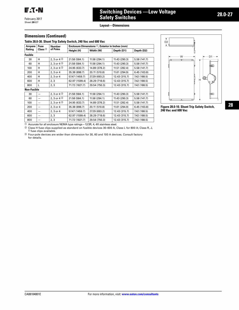
CA08104001E For more information, visit: www.eaton.com/consultants
28.0-27February 2017
Switching Devices —Low Voltage
Sheet 28
22
23
24
25
26
27
28
29
30
31
32
33
34
35
36
37
38
39
40
41
42
43
Safety SwitchesLayout—Dimensions
027
Dimensions (Continued)Table 28.0-30. Shunt Trip Safety Switch, 240 Vac and 600 Vac
a Accurate for all enclosure NEMA type ratings—12/3R, 4, 4X stainless steel.b Class H fuse clips supplied as standard on fusible devices 30–600 A, Class L for 800 A; Class R, J,
T fuse clips available.c Four-pole devices are wider than dimension for 30, 60 and 100 A devices. Consult factory
for details.
AmpereRating
Fuse Class b
Numberof Poles
Enclosure Dimensions a, Exterior in Inches (mm)
Height (H) Width (W) Depth (D1) Depth (D2)
Fusible30 H 2, 3 or 4 c 21.58 (584.1) 11.58 (294.1) 11.43 (290.3) 5.58 (141.7)
60 H 2, 3 or 4 c 21.58 (584.1) 11.58 (294.1) 11.43 (290.3) 5.58 (141.7)
100 H 2, 3 or 4 c 24.95 (633.7) 14.89 (378.2) 11.51 (282.4) 5.58 (141.7)
200 H 2, 3 or 4 35.38 (898.7) 20.11 (510.8) 11.61 (294.9) 6.45 (163.8)
400 H 2, 3 or 4 57.47 (1459.7) 27.29 (693.2) 12.43 (315.7) 7.42 (188.5)
600 H 2, 3 62.97 (1599.4) 28.29 (718.6) 12.43 (315.7) 7.42 (188.5)
800 L 2, 3 71.72 (1821.7) 29.54 (750.3) 12.43 (315.7) 7.42 (188.5)
Non-Fusible30 — 2, 3 or 4 c 21.58 (584.1) 11.58 (294.1) 11.43 (290.3) 5.58 (141.7)
60 — 2, 3 or 4 c 21.58 (584.1) 11.58 (294.1) 11.43 (290.3) 5.58 (141.7)
100 — 2, 3 or 4 c 24.95 (633.7) 14.89 (378.2) 11.51 (282.4) 5.58 (141.7)
200 — 2, 3 or 4 35.38 (898.7) 20.11 (510.8) 11.61 (294.9) 6.45 (163.8)
400 — 2, 3 or 4 57.47 (1459.7) 27.29 (693.2) 12.43 (315.7) 7.42 (188.5)
600 — 2, 3 62.97 (1599.4) 28.29 (718.6) 12.43 (315.7) 7.42 (188.5)
800 — 2, 3 71.72 (1821.7) 29.54 (750.3) 12.43 (315.7) 7.42 (188.5)
Figure 28.0-10. Shunt Trip Safety Switch, 240 Vac and 600 Vac
D1
H
W
D2
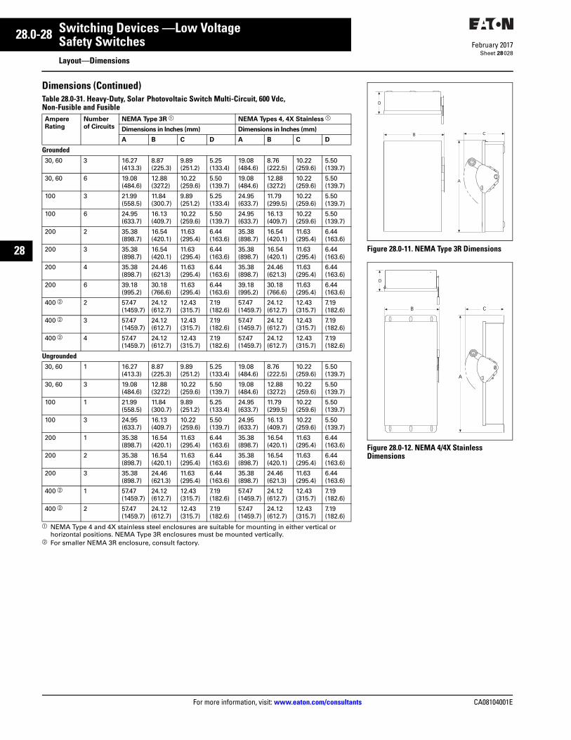
28.0-28
For more information, visit: www.eaton.com/consultants CA08104001E
February 2017
Switching Devices —Low Voltage
Sheet 28
22
23
24
25
26
27
28
29
30
31
32
33
34
35
36
37
38
39
40
41
42
43
Safety SwitchesLayout—Dimensions
028
Dimensions (Continued)Table 28.0-31. Heavy-Duty, Solar Photovoltaic Switch Multi-Circuit, 600 Vdc, Non-Fusible and Fusible
a NEMA Type 4 and 4X stainless steel enclosures are suitable for mounting in either vertical or horizontal positions. NEMA Type 3R enclosures must be mounted vertically.
b For smaller NEMA 3R enclosure, consult factory.
Ampere Rating
Number of Circuits
NEMA Type 3R a NEMA Types 4, 4X Stainless a
Dimensions in Inches (mm) Dimensions in Inches (mm)
A B C D A B C D
Grounded30, 60 3 16.27
(413.3)8.87(225.3)
9.89(251.2)
5.25(133.4)
19.08(484.6)
8.76(222.5)
10.22(259.6)
5.50(139.7)
30, 60 6 19.08(484.6)
12.88(327.2)
10.22(259.6)
5.50(139.7)
19.08(484.6)
12.88(327.2)
10.22(259.6)
5.50(139.7)
100 3 21.99(558.5)
11.84(300.7)
9.89(251.2)
5.25(133.4)
24.95(633.7)
11.79(299.5)
10.22(259.6)
5.50(139.7)
100 6 24.95(633.7)
16.13(409.7)
10.22(259.6)
5.50(139.7)
24.95(633.7)
16.13(409.7)
10.22(259.6)
5.50(139.7)
200 2 35.38(898.7)
16.54(420.1)
11.63(295.4)
6.44(163.6)
35.38(898.7)
16.54(420.1)
11.63(295.4)
6.44(163.6)
200 3 35.38(898.7)
16.54(420.1)
11.63(295.4)
6.44(163.6)
35.38(898.7)
16.54(420.1)
11.63(295.4)
6.44(163.6)
200 4 35.38(898.7)
24.46(621.3)
11.63(295.4)
6.44(163.6)
35.38(898.7)
24.46(621.3)
11.63(295.4)
6.44(163.6)
200 6 39.18(995.2)
30.18(766.6)
11.63(295.4)
6.44(163.6)
39.18(995.2)
30.18(766.6)
11.63(295.4)
6.44(163.6)
400 b 2 57.47(1459.7)
24.12(612.7)
12.43(315.7)
7.19(182.6)
57.47(1459.7)
24.12(612.7)
12.43(315.7)
7.19(182.6)
400 b 3 57.47(1459.7)
24.12(612.7)
12.43(315.7)
7.19(182.6)
57.47(1459.7)
24.12(612.7)
12.43(315.7)
7.19(182.6)
400 b 4 57.47(1459.7)
24.12(612.7)
12.43(315.7)
7.19(182.6)
57.47(1459.7)
24.12(612.7)
12.43(315.7)
7.19(182.6)
Ungrounded30, 60 1 16.27
(413.3)8.87(225.3)
9.89(251.2)
5.25(133.4)
19.08(484.6)
8.76(222.5)
10.22(259.6)
5.50(139.7)
30, 60 3 19.08(484.6)
12.88(327.2)
10.22(259.6)
5.50(139.7)
19.08(484.6)
12.88(327.2)
10.22(259.6)
5.50(139.7)
100 1 21.99(558.5)
11.84(300.7)
9.89(251.2)
5.25(133.4)
24.95(633.7)
11.79(299.5)
10.22(259.6)
5.50(139.7)
100 3 24.95(633.7)
16.13(409.7)
10.22(259.6)
5.50(139.7)
24.95(633.7)
16.13(409.7)
10.22(259.6)
5.50(139.7)
200 1 35.38(898.7)
16.54(420.1)
11.63(295.4)
6.44(163.6)
35.38(898.7)
16.54(420.1)
11.63(295.4)
6.44(163.6)
200 2 35.38(898.7)
16.54(420.1)
11.63(295.4)
6.44(163.6)
35.38(898.7)
16.54(420.1)
11.63(295.4)
6.44(163.6)
200 3 35.38(898.7)
24.46(621.3)
11.63(295.4)
6.44(163.6)
35.38(898.7)
24.46(621.3)
11.63(295.4)
6.44(163.6)
400 b 1 57.47(1459.7)
24.12(612.7)
12.43(315.7)
7.19(182.6)
57.47(1459.7)
24.12(612.7)
12.43(315.7)
7.19(182.6)
400 b 2 57.47(1459.7)
24.12(612.7)
12.43(315.7)
7.19(182.6)
57.47(1459.7)
24.12(612.7)
12.43(315.7)
7.19(182.6)
Figure 28.0-11. NEMA Type 3R Dimensions
Figure 28.0-12. NEMA 4/4X Stainless Dimensions
B C
A
D
B C
A
D
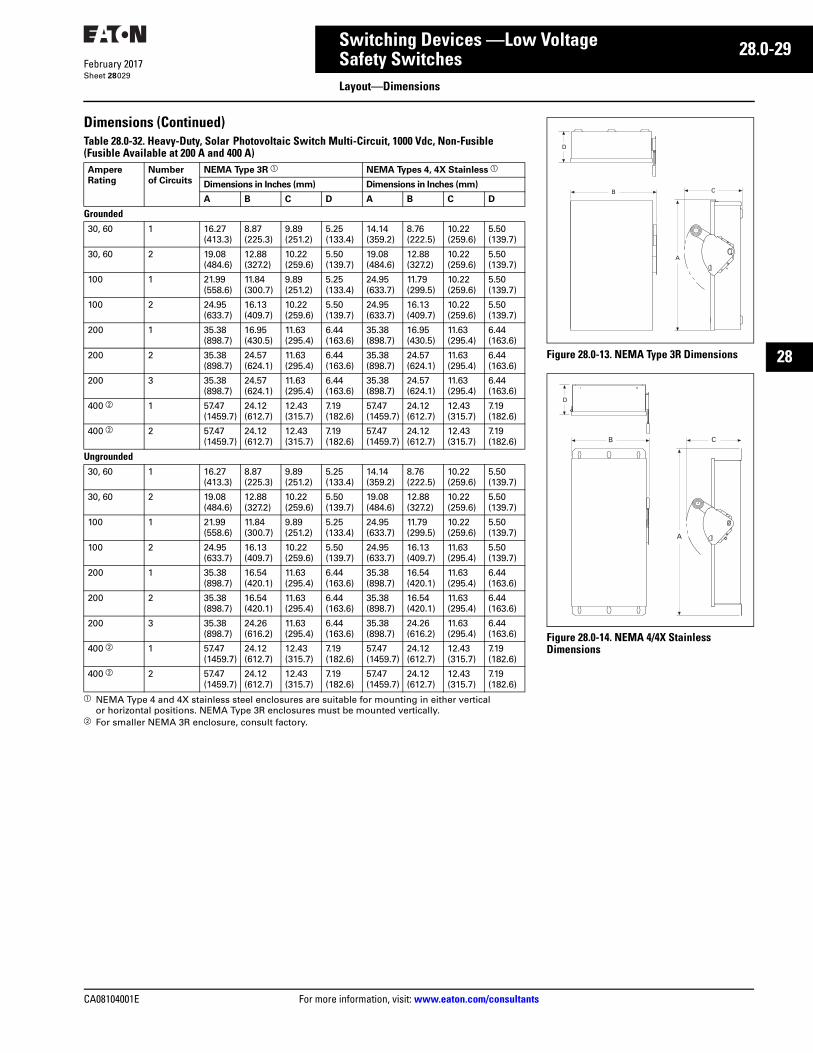
CA08104001E For more information, visit: www.eaton.com/consultants
28.0-29February 2017
Switching Devices —Low Voltage
Sheet 28
22
23
24
25
26
27
28
29
30
31
32
33
34
35
36
37
38
39
40
41
42
43
Safety SwitchesLayout—Dimensions
029
Dimensions (Continued)Table 28.0-32. Heavy-Duty, Solar Photovoltaic Switch Multi-Circuit, 1000 Vdc, Non-Fusible (Fusible Available at 200 A and 400 A)
a NEMA Type 4 and 4X stainless steel enclosures are suitable for mounting in either vertical or horizontal positions. NEMA Type 3R enclosures must be mounted vertically.
b For smaller NEMA 3R enclosure, consult factory.
AmpereRating
Number of Circuits
NEMA Type 3R a NEMA Types 4, 4X Stainless a
Dimensions in Inches (mm) Dimensions in Inches (mm)
A B C D A B C D
Grounded30, 60 1 16.27
(413.3)8.87(225.3)
9.89(251.2)
5.25(133.4)
14.14(359.2)
8.76(222.5)
10.22(259.6)
5.50(139.7)
30, 60 2 19.08(484.6)
12.88(327.2)
10.22(259.6)
5.50(139.7)
19.08(484.6)
12.88(327.2)
10.22(259.6)
5.50(139.7)
100 1 21.99(558.6)
11.84(300.7)
9.89(251.2)
5.25(133.4)
24.95(633.7)
11.79(299.5)
10.22(259.6)
5.50(139.7)
100 2 24.95(633.7)
16.13(409.7)
10.22(259.6)
5.50(139.7)
24.95(633.7)
16.13(409.7)
10.22(259.6)
5.50(139.7)
200 1 35.38(898.7)
16.95(430.5)
11.63(295.4)
6.44(163.6)
35.38(898.7)
16.95(430.5)
11.63(295.4)
6.44(163.6)
200 2 35.38(898.7)
24.57(624.1)
11.63(295.4)
6.44(163.6)
35.38(898.7)
24.57(624.1)
11.63(295.4)
6.44(163.6)
200 3 35.38(898.7)
24.57(624.1)
11.63(295.4)
6.44(163.6)
35.38(898.7)
24.57(624.1)
11.63(295.4)
6.44(163.6)
400 b 1 57.47(1459.7)
24.12(612.7)
12.43(315.7)
7.19(182.6)
57.47(1459.7)
24.12(612.7)
12.43(315.7)
7.19(182.6)
400 b 2 57.47(1459.7)
24.12(612.7)
12.43(315.7)
7.19(182.6)
57.47(1459.7)
24.12(612.7)
12.43(315.7)
7.19(182.6)
Ungrounded30, 60 1 16.27
(413.3)8.87(225.3)
9.89(251.2)
5.25(133.4)
14.14(359.2)
8.76(222.5)
10.22(259.6)
5.50(139.7)
30, 60 2 19.08(484.6)
12.88(327.2)
10.22(259.6)
5.50(139.7)
19.08(484.6)
12.88(327.2)
10.22(259.6)
5.50(139.7)
100 1 21.99(558.6)
11.84(300.7)
9.89(251.2)
5.25(133.4)
24.95(633.7)
11.79(299.5)
10.22(259.6)
5.50(139.7)
100 2 24.95(633.7)
16.13(409.7)
10.22(259.6)
5.50(139.7)
24.95(633.7)
16.13(409.7)
11.63(295.4)
5.50(139.7)
200 1 35.38(898.7)
16.54(420.1)
11.63(295.4)
6.44(163.6)
35.38(898.7)
16.54(420.1)
11.63(295.4)
6.44(163.6)
200 2 35.38(898.7)
16.54(420.1)
11.63(295.4)
6.44(163.6)
35.38(898.7)
16.54(420.1)
11.63(295.4)
6.44(163.6)
200 3 35.38(898.7)
24.26(616.2)
11.63(295.4)
6.44(163.6)
35.38(898.7)
24.26(616.2)
11.63(295.4)
6.44(163.6)
400 b 1 57.47(1459.7)
24.12(612.7)
12.43(315.7)
7.19(182.6)
57.47(1459.7)
24.12(612.7)
12.43(315.7)
7.19(182.6)
400 b 2 57.47(1459.7)
24.12(612.7)
12.43(315.7)
7.19(182.6)
57.47(1459.7)
24.12(612.7)
12.43(315.7)
7.19(182.6)
Figure 28.0-13. NEMA Type 3R Dimensions
Figure 28.0-14. NEMA 4/4X Stainless Dimensions
B C
A
D
B C
A
D
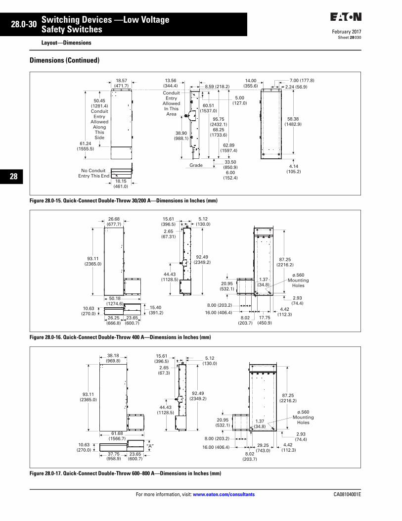
28.0-30
For more information, visit: www.eaton.com/consultants CA08104001E
February 2017
Switching Devices —Low Voltage
Sheet 28
22
23
24
25
26
27
28
29
30
31
32
33
34
35
36
37
38
39
40
41
42
43
Safety SwitchesLayout—Dimensions
030
Dimensions (Continued)
Figure 28.0-15. Quick-Connect Double-Throw 30/200 A—Dimensions in Inches (mm)
Figure 28.0-16. Quick-Connect Double-Throw 400 A—Dimensions in Inches (mm)
Figure 28.0-17. Quick-Connect Double-Throw 600–800 A—Dimensions in Inches (mm)
18.57(471.7)
50.45(1281.4)Conduit
EntryAllowedAlongThisSide
61.24(1555.5)
18.15(461.0)
No Conduit Entry This End
13.56(344.4) 8.59 (218.2)Conduit
EntryAllowedIn ThisArea
5.00(127.0)60.51
(1537.0)
95.75(2432.1)
68.25(1733.6)
62.89(1597.4)
33.50(850.9)
6.00(152.4)
Grade
14.00(355.6) 2.24 (56.9)
7.00 (177.8)
58.38(1482.9)
4.14(105.2)
38.90(988.1)
23.65(600.7)
93.11(2365.0)
26.68(677.7)
50.18(1274.6)
10.63(270.0)
26.25(666.8)
15.61(396.5)
5.12(130.0)
2.65(67.31)
44.43(1128.5)
92.49(2349.2)
17.75(450.9)
16.00 (406.4)8.02
(203.7)
8.00 (203.2)4.42
(112.3)
1.37(34.8)
2.93(74.4)
20.95(532.1)
ø.560Mounting
Holes
87.25(2216.2)
15.40(391.2)
15.61(396.5)
29.25(743.0)
16.00 (406.4)8.02
(203.7)
8.00 (203.2)
“A”
23.65(600.7)
37.75(958.9)
38.18(969.8)
61.68(1566.7)
5.12(130.0)
4.42(112.3)
93.11(2365.0)
10.63(270.0)
2.65(67.3)
44.43(1128.5)
92.49(2349.2)
1.37(34.8)
2.93(74.4)
20.95(532.1)
ø.560Mounting
Holes
87.25(2216.2)
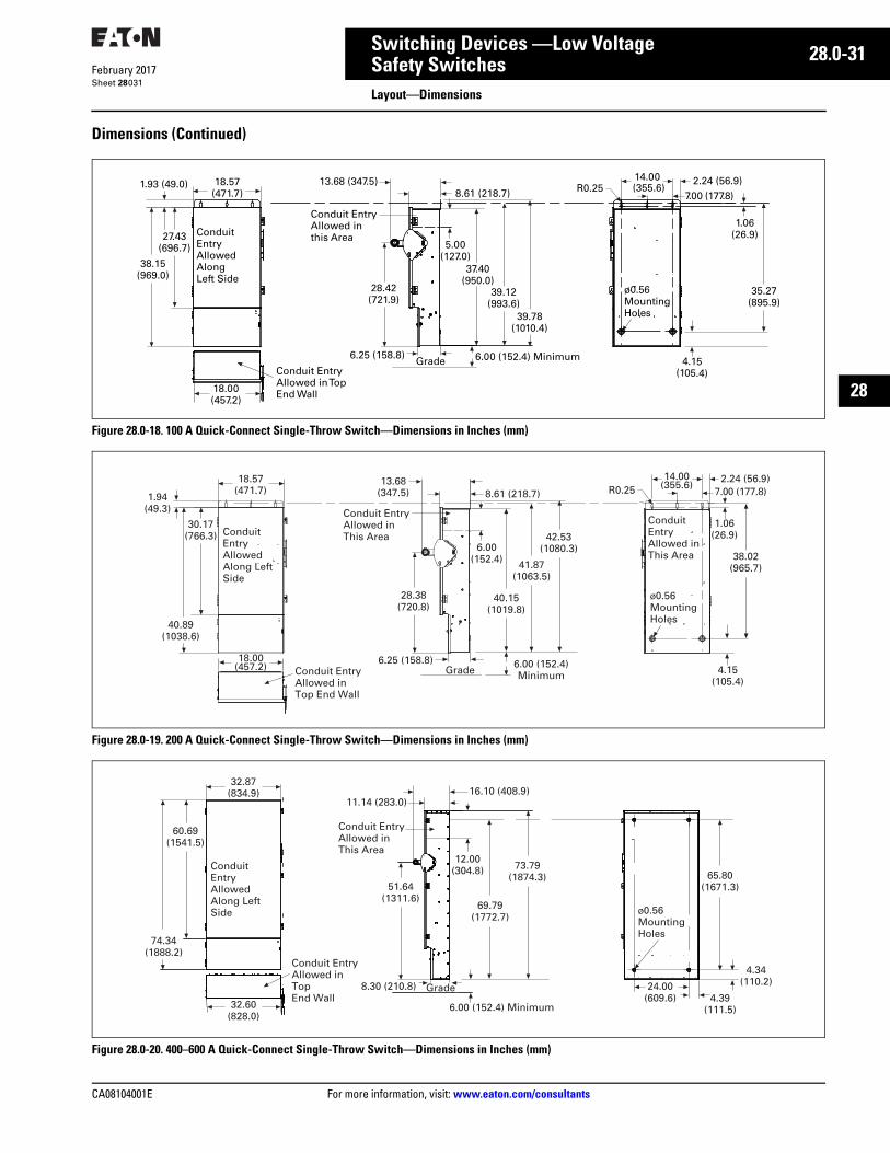
CA08104001E For more information, visit: www.eaton.com/consultants
28.0-31February 2017
Switching Devices —Low Voltage
Sheet 28
22
23
24
25
26
27
28
29
30
31
32
33
34
35
36
37
38
39
40
41
42
43
Safety SwitchesLayout—Dimensions
031
Dimensions (Continued)
Figure 28.0-18. 100 A Quick-Connect Single-Throw Switch—Dimensions in Inches (mm)
Figure 28.0-19. 200 A Quick-Connect Single-Throw Switch—Dimensions in Inches (mm)
Figure 28.0-20. 400–600 A Quick-Connect Single-Throw Switch—Dimensions in Inches (mm)
27.43(696.7)
38.15(969.0)
18.57(471.7)
1.93 (49.0)
6.25 (158.8)
28.42(721.9)
13.68 (347.5)
8.61 (218.7)
37.40(950.0)
39.12(993.6)
39.78(1010.4)
2.24 (56.9)
7.00 (177.8)
14.00 (355.6)
35.27(895.9)
4.15(105.4)
6.00 (152.4) Minimum
5.00(127.0)
18.00(457.2)
R0.25
1.06(26.9)Conduit
Entry Allowed Along Left Side
ø0.56Mounting Holes
GradeConduit Entry Allowed in Top End Wall
Conduit Entry Allowed in this Area
18.00(457.2)
18.57(471.7)
40.89(1038.6)
30.17(766.3)
1.94(49.3)
Conduit EntryAllowed in Top End Wall
Conduit EntryAllowed Along Left Side
ø0.56MountingHoles
Conduit Entry Allowed inThis Area
Conduit Entry Allowed in This Area
13.68(347.5)
6.00 (152.4)
42.53(1080.3)
28.38(720.8)
41.87(1063.5)
40.15(1019.8)
6.00 (152.4) Minimum
6.25 (158.8)Grade
8.61 (218.7)
14.00(355.6)
2.24 (56.9)
1.06(26.9)
R0.25 7.00 (177.8)
38.02(965.7)
4.15(105.4)
32.60(828.0)
Conduit Entry Allowed in Top End Wall
32.87(834.9)
60.69(1541.5)
74.34(1888.2)
Conduit EntryAllowed inThis Area
Conduit EntryAllowed Along Left Side
16.10 (408.9)
6.00 (152.4) Minimum
11.14 (283.0)
12.00(304.8) 73.79
(1874.3)
69.79(1772.7)
51.64(1311.6)
8.30 (210.8) Grade
ø0.56MountingHoles
24.00(609.6) 4.39
(111.5)
4.34(110.2)
65.80(1671.3)

28.0-32
For more information, visit: www.eaton.com/consultants CA08104001E
February 2017
Switching Devices —Low Voltage
Sheet 28
22
23
24
25
26
27
28
29
30
31
32
33
34
35
36
37
38
39
40
41
42
43
Safety SwitchesLayout—Dimensions
032
Dimensions (Continued)
Figure 28.0-21. 800 A Quick-Connect Single-Throw Switch—Dimensions in Inches (mm)
ø0.56MountingHoles
32.87(834.9)
60.69(1541.5)
85.59(2174.0)
Conduit Entry Allowed Along Left Side
Conduit EntryAllowed inThis Area
21.73 (551.9)16.79 (426.5)
32.60 (828.0)
Conduit EntryAllowed in Top End Wall
12.00(304.8)
85.04(2160.0)
81.03(2058.2)
62.23(1580.6)
Grade
6.00 (152.4) Minimum
13.96 (354.6)
77.05(1957.1)
24.00(609.6)
4.34(110.2)
4.39(111.5)
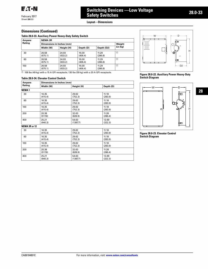
CA08104001E For more information, visit: www.eaton.com/consultants
28.0-33February 2017
Switching Devices —Low Voltage
Sheet 28
22
23
24
25
26
27
28
29
30
31
32
33
34
35
36
37
38
39
40
41
42
43
Safety SwitchesLayout—Dimensions
033
Dimensions (Continued)Table 28.0-33. Auxiliary Power Heavy-Duty Safety Switch
a 108 lbs (49 kg) with a 15 A GFI receptacle; 130 lbs (59 kg) with a 20 A GFI receptacle.
Table 28.0-34. Elevator Control Switch
AmpereRating
NEMA 3R
Dimensions in Inches (mm) WeightLb (kg)Width (W) Height (H) Depth (D) Depth (D2)
30 26.58 (675.1)
24.93 (633.2)
16.00 (406.4)
11.29 (286.8)
a
60 26.58 (675.1)
24.93 (633.2)
16.00 (406.4)
11.29 (286.8)
a
100 26.58 (675.1)
24.93 (633.2)
16.00 (406.4)
11.29 (286.8)
a
AmpereRating
Dimensions in Inches (mm)
Width (W) Height (H) Depth (D)
NEMA 130 16.35
(415.4)29.62 (752.3)
11.18 (283.9)
60 16.35 (415.4)
29.62 (752.3)
11.18 (283.9)
100 16.35 (415.4)
29.62 (752.3)
11.18 (283.9)
200 20.38 (517.8)
32.63 (828.9)
11.28(286.4)
400 25.21 (640.3)
54.63 (1387.7)
12.69(322.3)
NEMA 3R or 1230 16.35
(415.4)29.62 (752.3)
11.18 (283.9)
60 16.35 (415.4)
29.62 (752.3)
11.18 (283.9)
100 16.35(415.4)
29.62 (752.3)
11.18 (283.9)
200 20.38 (517.8)
32.63 (828.9)
11.28 (286.4)
400 25.21 (640.3)
54.63 (1387.7)
12.69(322.3)
Figure 28.0-22. Auxiliary Power Heavy-Duty Switch Diagram
Figure 28.0-23. Elevator Control Switch Diagram
W
D2
D
H
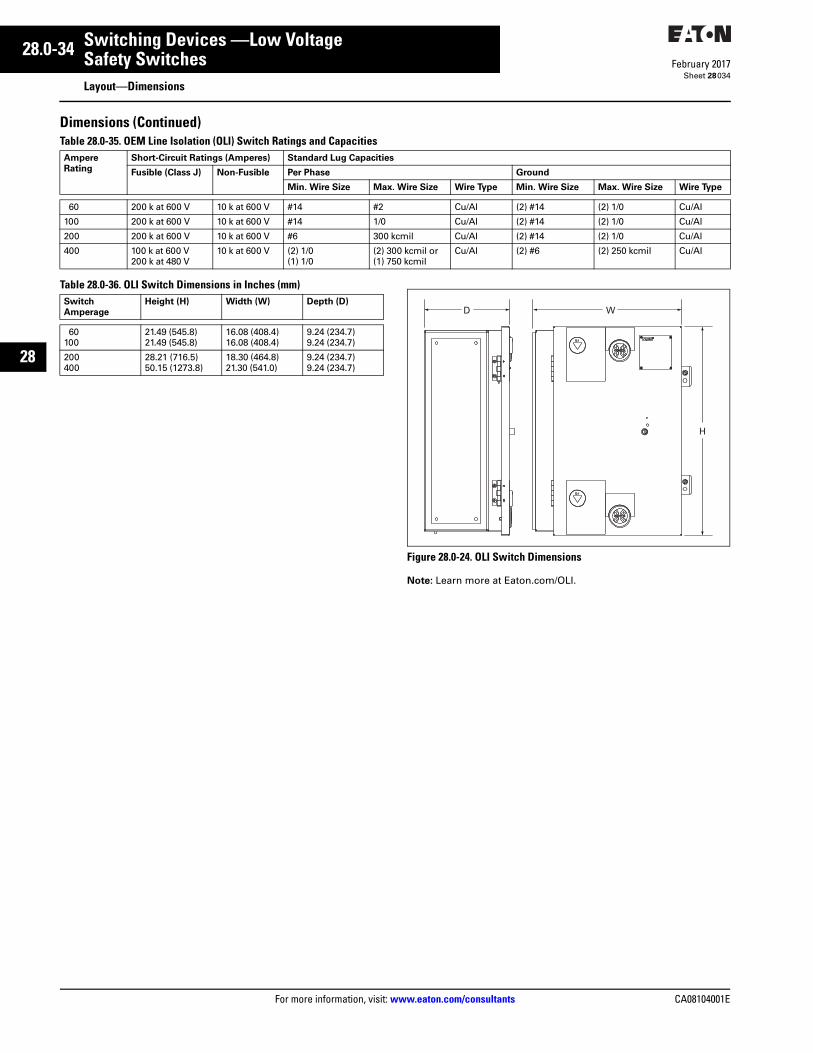
28.0-34
For more information, visit: www.eaton.com/consultants CA08104001E
February 2017
Switching Devices —Low Voltage
Sheet 28
22
23
24
25
26
27
28
29
30
31
32
33
34
35
36
37
38
39
40
41
42
43
Safety SwitchesLayout—Dimensions
034
Dimensions (Continued)Table 28.0-35. OEM Line Isolation (OLI) Switch Ratings and Capacities
Table 28.0-36. OLI Switch Dimensions in Inches (mm)
Figure 28.0-24. OLI Switch Dimensions
Note: Learn more at Eaton.com/OLI.
Ampere Rating
Short-Circuit Ratings (Amperes) Standard Lug Capacities
Fusible (Class J) Non-Fusible Per Phase Ground
Min. Wire Size Max. Wire Size Wire Type Min. Wire Size Max. Wire Size Wire Type
60 200 k at 600 V 10 k at 600 V #14 #2 Cu/Al (2) #14 (2) 1/0 Cu/Al
100 200 k at 600 V 10 k at 600 V #14 1/0 Cu/Al (2) #14 (2) 1/0 Cu/Al
200 200 k at 600 V 10 k at 600 V #6 300 kcmil Cu/Al (2) #14 (2) 1/0 Cu/Al
400 100 k at 600 V200 k at 480 V
10 k at 600 V (2) 1/0(1) 1/0
(2) 300 kcmil or(1) 750 kcmil
Cu/Al (2) #6 (2) 250 kcmil Cu/Al
SwitchAmperage
Height (H) Width (W) Depth (D)
60100
21.49 (545.8)21.49 (545.8)
16.08 (408.4)16.08 (408.4)
9.24 (234.7)9.24 (234.7)
200400
28.21 (716.5)50.15 (1273.8)
18.30 (464.8)21.30 (541.0)
9.24 (234.7)9.24 (234.7)
D W
H
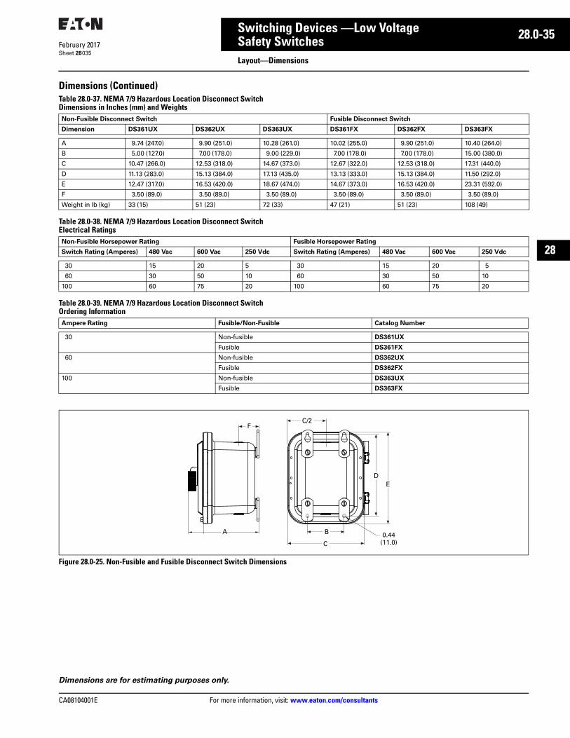
CA08104001E For more information, visit: www.eaton.com/consultants
28.0-35February 2017
Switching Devices —Low Voltage
Sheet 28
22
23
24
25
26
27
28
29
30
31
32
33
34
35
36
37
38
39
40
41
42
43
Safety SwitchesLayout—Dimensions
035
Dimensions (Continued)Table 28.0-37. NEMA 7/9 Hazardous Location Disconnect Switch Dimensions in Inches (mm) and Weights
Table 28.0-38. NEMA 7/9 Hazardous Location Disconnect Switch Electrical Ratings
Table 28.0-39. NEMA 7/9 Hazardous Location Disconnect Switch Ordering Information
Figure 28.0-25. Non-Fusible and Fusible Disconnect Switch Dimensions
Non-Fusible Disconnect Switch Fusible Disconnect Switch
Dimension DS361UX DS362UX DS363UX DS361FX DS362FX DS363FX
A 9.74 (247.0) 9.90 (251.0) 10.28 (261.0) 10.02 (255.0) 9.90 (251.0) 10.40 (264.0)
B 5.00 (127.0) 7.00 (178.0) 9.00 (229.0) 7.00 (178.0) 7.00 (178.0) 15.00 (380.0)
C 10.47 (266.0) 12.53 (318.0) 14.67 (373.0) 12.67 (322.0) 12.53 (318.0) 17.31 (440.0)
D 11.13 (283.0) 15.13 (384.0) 17.13 (435.0) 13.13 (333.0) 15.13 (384.0) 11.50 (292.0)
E 12.47 (317.0) 16.53 (420.0) 18.67 (474.0) 14.67 (373.0) 16.53 (420.0) 23.31 (592.0)
F 3.50 (89.0) 3.50 (89.0) 3.50 (89.0) 3.50 (89.0) 3.50 (89.0) 3.50 (89.0)
Weight in lb (kg) 33 (15) 51 (23) 72 (33) 47 (21) 51 (23) 108 (49)
Non-Fusible Horsepower Rating Fusible Horsepower Rating
Switch Rating (Amperes) 480 Vac 600 Vac 250 Vdc Switch Rating (Amperes) 480 Vac 600 Vac 250 Vdc
30 15 20 5 30 15 20 5
60 30 50 10 60 30 50 10
100 60 75 20 100 60 75 20
Ampere Rating Fusible/Non-Fusible Catalog Number
30 Non-fusible DS361UX
Fusible DS361FX
60 Non-fusible DS362UX
Fusible DS362FX
100 Non-fusible DS363UX
Fusible DS363FX
C/2F
A B
C
ED
0.44(11.0)
Dimensions are for estimating purposes only.
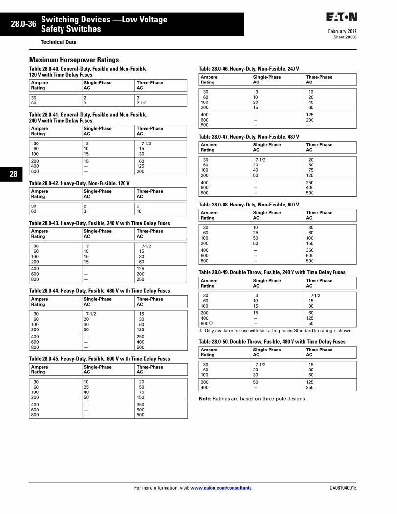
28.0-36
For more information, visit: www.eaton.com/consultants CA08104001E
February 2017
Switching Devices —Low Voltage
Sheet 28
22
23
24
25
26
27
28
29
30
31
32
33
34
35
36
37
38
39
40
41
42
43
Safety SwitchesTechnical Data
036
Maximum Horsepower RatingsTable 28.0-40. General-Duty, Fusible and Non-Fusible, 120 V with Time Delay Fuses
Table 28.0-41. General-Duty, Fusible and Non-Fusible, 240 V with Time Delay Fuses
Table 28.0-42. Heavy-Duty, Non-Fusible, 120 V
Table 28.0-43. Heavy-Duty, Fusible, 240 V with Time Delay Fuses
Table 28.0-44. Heavy-Duty, Fusible, 480 V with Time Delay Fuses
Table 28.0-45. Heavy-Duty, Fusible, 600 V with Time Delay Fuses
Table 28.0-46. Heavy-Duty, Non-Fusible, 240 V
Table 28.0-47. Heavy-Duty, Non-Fusible, 480 V
Table 28.0-48. Heavy-Duty, Non-Fusible, 600 V
Table 28.0-49. Double Throw, Fusible, 240 V with Time Delay Fuses
a Only available for use with fast acting fuses. Standard hp rating is shown.
Table 28.0-50. Double Throw, Fusible, 480 V with Time Delay Fuses
Note: Ratings are based on three-pole designs.
Ampere Rating
Single-Phase AC
Three-Phase AC
3060
23
37-1/2
Ampere Rating
Single-Phase AC
Three-Phase AC
3060
100
31015
7-1/21530
200400600
15——
60125200
Ampere Rating
Single-Phase AC
Three-Phase AC
3060
23
510
Ampere Rating
Single-Phase AC
Three-Phase AC
3060
100200
3101515
7-1/2153060
400600800
———
125200250
Ampere Rating
Single-Phase AC
Three-Phase AC
3060
100200
7-1/2203050
153060
125
400600800
———
250400500
Ampere Rating
Single-Phase AC
Three-Phase AC
3060
100200
10254050
205075
150
400600800
———
350500500
Ampere Rating
Single-Phase AC
Three-Phase AC
3060
100200
3102015
10204060
400600800
———
125200—
Ampere Rating
Single-Phase AC
Three-Phase AC
3060
100200
7-1/2204050
205075
125
400600800
———
250400500
Ampere Rating
Single-Phase AC
Three-Phase AC
3060
100200
10255050
3060
100150
400600800
———
350500500
Ampere Rating
Single-Phase AC
Three-Phase AC
3060
100
31015
7-1/21530
200400600 a
15——
6012550
Ampere Rating
Single-Phase AC
Three-Phase AC
3060
100
7-1/22030
153060
200400
50—
125250
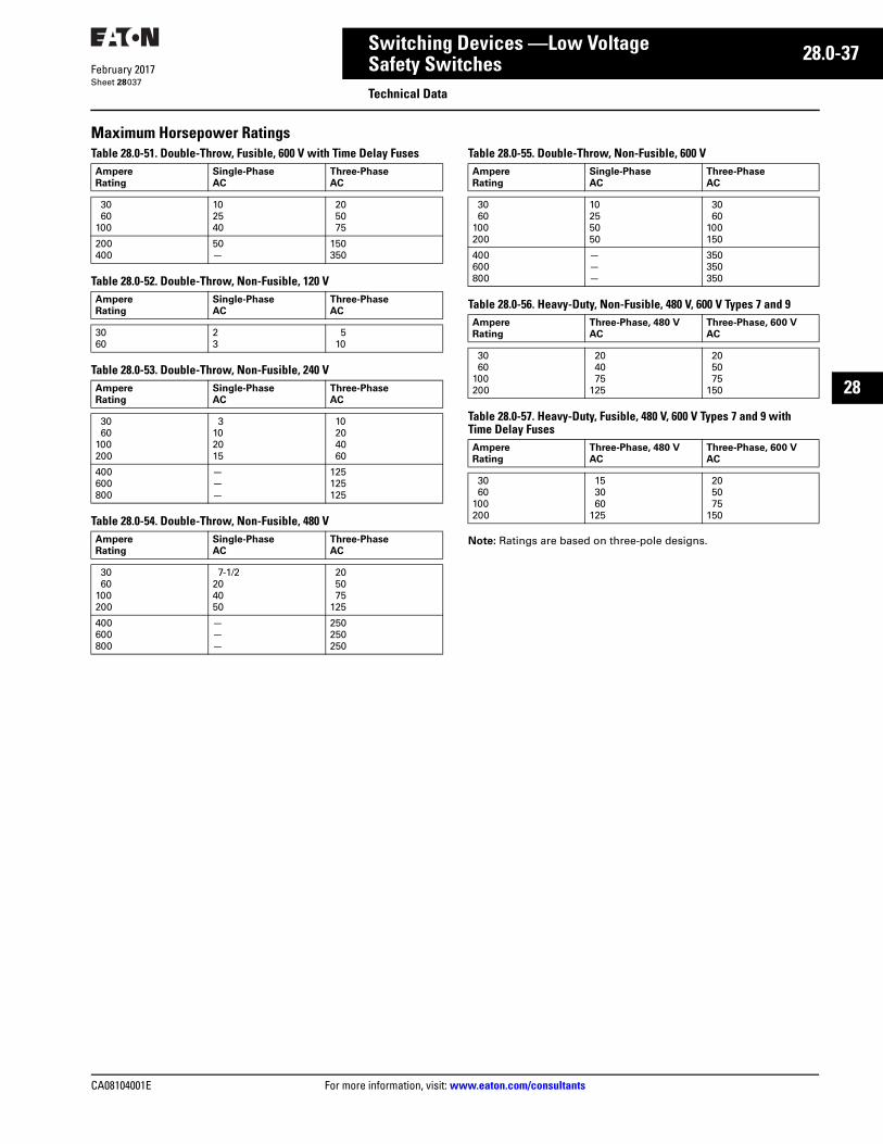
CA08104001E For more information, visit: www.eaton.com/consultants
28.0-37February 2017
Switching Devices —Low Voltage
Sheet 28
22
23
24
25
26
27
28
29
30
31
32
33
34
35
36
37
38
39
40
41
42
43
Safety SwitchesTechnical Data
037
Maximum Horsepower RatingsTable 28.0-51. Double-Throw, Fusible, 600 V with Time Delay Fuses
Table 28.0-52. Double-Throw, Non-Fusible, 120 V
Table 28.0-53. Double-Throw, Non-Fusible, 240 V
Table 28.0-54. Double-Throw, Non-Fusible, 480 V
Table 28.0-55. Double-Throw, Non-Fusible, 600 V
Table 28.0-56. Heavy-Duty, Non-Fusible, 480 V, 600 V Types 7 and 9
Table 28.0-57. Heavy-Duty, Fusible, 480 V, 600 V Types 7 and 9 with Time Delay Fuses
Note: Ratings are based on three-pole designs.
Ampere Rating
Single-Phase AC
Three-Phase AC
3060
100
102540
205075
200400
50—
150350
Ampere Rating
Single-Phase AC
Three-Phase AC
3060
23
510
Ampere Rating
Single-Phase AC
Three-Phase AC
3060
100200
3102015
10204060
400600800
———
125125125
Ampere Rating
Single-Phase AC
Three-Phase AC
3060
100200
7-1/2204050
205075
125
400600800
———
250250250
Ampere Rating
Single-Phase AC
Three-Phase AC
3060
100200
10255050
3060
100150
400600800
———
350350350
Ampere Rating
Three-Phase, 480 VAC
Three-Phase, 600 VAC
3060
100200
204075
125
205075
150
Ampere Rating
Three-Phase, 480 VAC
Three-Phase, 600 VAC
3060
100200
153060
125
205075
150
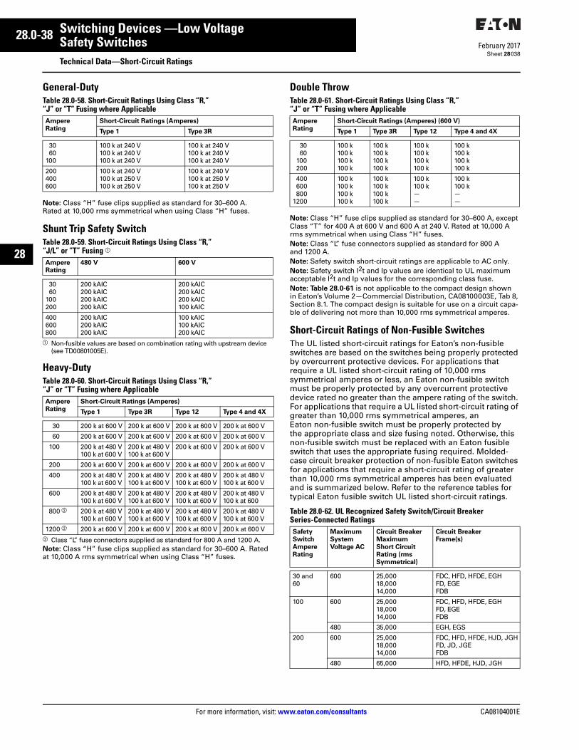
28.0-38
For more information, visit: www.eaton.com/consultants CA08104001E
February 2017
Switching Devices —Low Voltage
Sheet 28
22
23
24
25
26
27
28
29
30
31
32
33
34
35
36
37
38
39
40
41
42
43
Safety SwitchesTechnical Data—Short-Circuit Ratings
038
General-DutyTable 28.0-58. Short-Circuit Ratings Using Class “R,” “J” or “T” Fusing where Applicable
Note: Class “H” fuse clips supplied as standard for 30–600 A. Rated at 10,000 rms symmetrical when using Class “H” fuses.
Shunt Trip Safety SwitchTable 28.0-59. Short-Circuit Ratings Using Class “R,” “J/L” or “T” Fusing a
a Non-fusible values are based on combination rating with upstream device (see TD00801005E).
Heavy-DutyTable 28.0-60. Short-Circuit Ratings Using Class “R,” “J” or “T” Fusing where Applicable
b Class “L” fuse connectors supplied as standard for 800 A and 1200 A.Note: Class “H” fuse clips supplied as standard for 30–600 A. Rated at 10,000 A rms symmetrical when using Class “H” fuses.
Double ThrowTable 28.0-61. Short-Circuit Ratings Using Class “R,” “J” or “T” Fusing where Applicable
Note: Class “H” fuse clips supplied as standard for 30–600 A, except Class “T” for 400 A at 600 V and 600 A at 240 V. Rated at 10,000 A rms symmetrical when using Class “H” fuses.Note: Class “L” fuse connectors supplied as standard for 800 A and 1200 A.Note: Safety switch short-circuit ratings are applicable to AC only.Note: Safety switch I2t and Ip values are identical to UL maximum acceptable I2t and Ip values for the corresponding class fuse.Note: Table 28.0-61 is not applicable to the compact design shownin Eaton’s Volume 2—Commercial Distribution, CA08100003E, Tab 8, Section 8.1. The compact design is suitable for use on a circuit capa-ble of delivering not more than 10,000 rms symmetrical amperes.
Short-Circuit Ratings of Non-Fusible SwitchesThe UL listed short-circuit ratings for Eaton’s non-fusible switches are based on the switches being properly protected by overcurrent protective devices. For applications that require a UL listed short-circuit rating of 10,000 rms symmetrical amperes or less, an Eaton non-fusible switch must be properly protected by any overcurrent protective device rated no greater than the ampere rating of the switch. For applications that require a UL listed short-circuit rating of greater than 10,000 rms symmetrical amperes, an Eaton non-fusible switch must be properly protected by the appropriate class and size fusing noted. Otherwise, this non-fusible switch must be replaced with an Eaton fusible switch that uses the appropriate fusing required. Molded-case circuit breaker protection of non-fusible Eaton switches for applications that require a short-circuit rating of greater than 10,000 rms symmetrical amperes has been evaluated and is summarized below. Refer to the reference tables for typical Eaton fusible switch UL listed short-circuit ratings.
Table 28.0-62. UL Recognized Safety Switch/Circuit Breaker Series-Connected Ratings
Ampere Rating
Short-Circuit Ratings (Amperes)
Type 1 Type 3R
3060
100
100 k at 240 V100 k at 240 V100 k at 240 V
100 k at 240 V100 k at 240 V100 k at 240 V
200400600
100 k at 240 V100 k at 250 V100 k at 250 V
100 k at 240 V100 k at 250 V100 k at 250 V
Ampere Rating
480 V 600 V
3060
100200
200 kAIC200 kAIC200 kAIC200 kAIC
200 kAIC200 kAIC200 kAIC100 kAIC
400600800
200 kAIC200 kAIC200 kAIC
100 kAIC100 kAIC200 kAIC
Ampere Rating
Short-Circuit Ratings (Amperes)
Type 1 Type 3R Type 12 Type 4 and 4X
30 200 k at 600 V 200 k at 600 V 200 k at 600 V 200 k at 600 V
60 200 k at 600 V 200 k at 600 V 200 k at 600 V 200 k at 600 V
100 200 k at 480 V100 k at 600 V
200 k at 480 V100 k at 600 V
200 k at 600 V 200 k at 600 V
200 200 k at 600 V 200 k at 600 V 200 k at 600 V 200 k at 600 V
400 200 k at 480 V100 k at 600 V
200 k at 480 V100 k at 600 V
200 k at 480 V100 k at 600 V
200 k at 480 V100 k at 600 V
600 200 k at 480 V100 k at 600 V
200 k at 480 V100 k at 600 V
200 k at 480 V100 k at 600 V
200 k at 480 V100 k at 600
800 b 200 k at 480 V100 k at 600 V
200 k at 480 V100 k at 600 V
200 k at 480 V100 k at 600 V
200 k at 480 V100 k at 600 V
1200 b 200 k at 600 V 200 k at 600 V 200 k at 600 V 200 k at 600 V
Ampere Rating
Short-Circuit Ratings (Amperes) (600 V)
Type 1 Type 3R Type 12 Type 4 and 4X
3060
100200
100 k100 k100 k100 k
100 k100 k100 k100 k
100 k100 k100 k100 k
100 k100 k100 k100 k
400600800
1200
100 k100 k100 k100 k
100 k100 k100 k100 k
100 k100 k——
100 k100 k——
Safety SwitchAmpere Rating
MaximumSystem Voltage AC
Circuit BreakerMaximum Short Circuit Rating (rmsSymmetrical)
Circuit Breaker Frame(s)
30 and 60
600 25,00018,00014,000
FDC, HFD, HFDE, EGHFD, EGEFDB
100 600 25,00018,00014,000
FDC, HFD, HFDE, EGHFD, EGEFDB
480 35,000 EGH, EGS
200 600 25,00018,00014,000
FDC, HFD, HFDE, HJD, JGHFD, JD, JGEFDB
480 65,000 HFD, HFDE, HJD, JGH
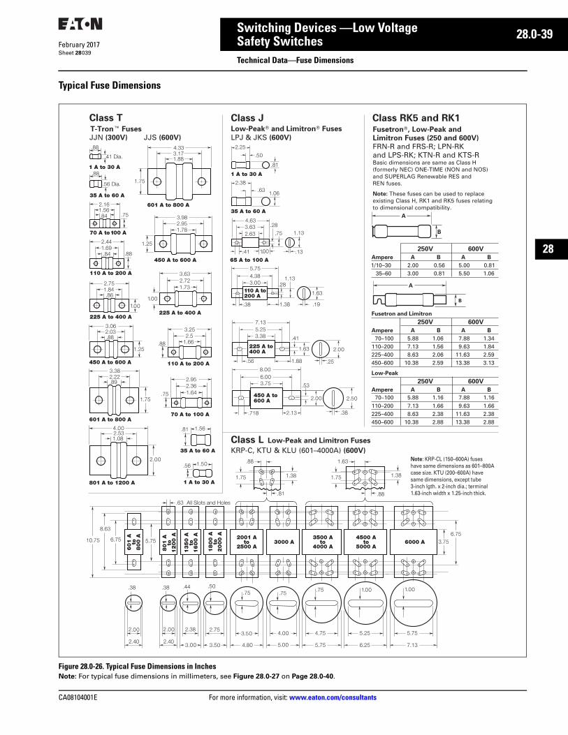
CA08104001E For more information, visit: www.eaton.com/consultants
28.0-39February 2017
Switching Devices —Low Voltage
Sheet 28
22
23
24
25
26
27
28
29
30
31
32
33
34
35
36
37
38
39
40
41
42
43
Safety SwitchesTechnical Data—Fuse Dimensions
039
Typical Fuse Dimensions
Figure 28.0-26. Typical Fuse Dimensions in InchesNote: For typical fuse dimensions in millimeters, see Figure 28.0-27 on Page 28.0-40.
A
B
250V 600V
Ampere A B A B
1/10–30 2.00 0.56 5.00 0.8135–60 3.00 0.81 5.50 1.06
250V 600V
Ampere A B A B
70–100 5.88 1.06 7.88 1.34110–200 7.13 1.56 9.63 1.84225–400 8.63 2.06 11.63 2.59450–600 10.38 2.59 13.38 3.13
250V 600V
Ampere A B A B
110–200 7.13 1.66 9.63 1.66225–400 8.63 2.38 11.63 2.38450–600 10.38 2.88 13.38 2.88
A
B
T-Tron� Fuses
JJN (300V) JJS (600V)
Class JLow-Peak� and Limitron� Fuses
LPJ & JKS (600V)
Class L Low-Peak and Limitron Fuses
KRP-C, KTU & KLU (601–4000A) (600V) Note: KRP-CL (150–600A) fuseshave same dimensions as 601–800A case size. KTU (200–600A) have same dimensions, except tube3-inch lgth. x 2-inch dia.; terminal1.63-inch width x 1.25-inch thick.
Class RK5 and RK1Class TFusetron�, Low-Peak and
Limitron Fuses (250 and 600V)
FRN-R and FRS-R; LPN-RK and LPS-RK; KTN-R and KTS-RBasic dimensions are same as Class H (formerly NEC) ONE-TIME (NON and NOS) and SUPERLAG Renewable RES and REN fuses.
Note: These fuses can be used to replace existing Class H, RK1 and RK5 fuses relating to dimensional compatibility.
70–100 5.88 1.16 7.88 1.16
Low-Peak
Fusetron and Limitron
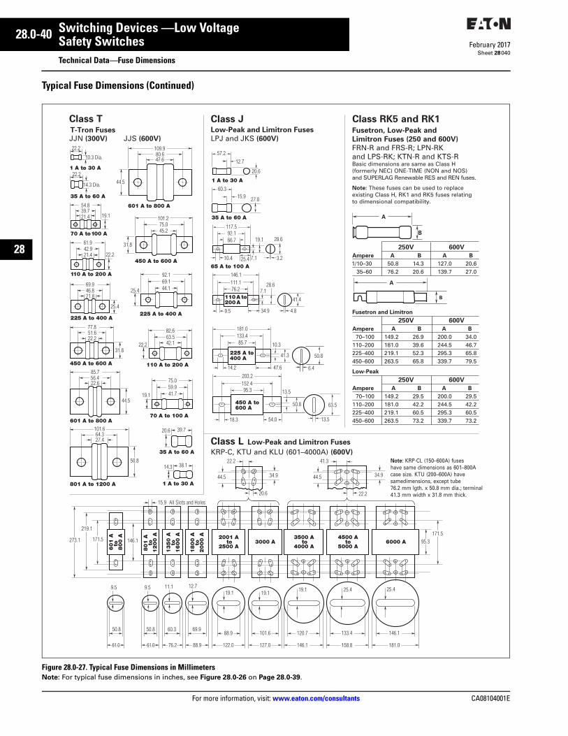
28.0-40
For more information, visit: www.eaton.com/consultants CA08104001E
February 2017
Switching Devices —Low Voltage
Sheet 28
22
23
24
25
26
27
28
29
30
31
32
33
34
35
36
37
38
39
40
41
42
43
Safety SwitchesTechnical Data—Fuse Dimensions
040
Typical Fuse Dimensions (Continued)
Figure 28.0-27. Typical Fuse Dimensions in MillimetersNote: For typical fuse dimensions in inches, see Figure 28.0-26 on Page 28.0-39.
A
B
T-Tron Fuses
JJN (300V) JJS (600V)
Class JLow-Peak and Limitron Fuses
LPJ and JKS (600V)
Class L Low-Peak and Limitron Fuses
KRP-C, KTU and KLU (601–4000A) (600V) Note: KRP-CL (150–600A) fuseshave same dimensions as 601–800Acase size. KTU (200–600A) have samedimensions, except tube76.2 mm lgth. x 50.8 mm dia.; terminal41.3 mm width x 31.8 mm thick.
Class RK5 and RK1
250V 600V
Ampere A B A B
1/10–30 50.8 14.3 127.0 20.635–60 76.2 20.6 139.7 27.0
250V 600V
Ampere A B A B
70–100 149.2 26.9 200.0 34.0110–200 181.0 39.6 244.5 46.7225–400 219.1 52.3 295.3 65.8450–600 263.5 65.8 339.7 79.5
250V 600V
Ampere A B A B
70–100 149.2 29.5 200.0 29.5110–200 181.0 42.2 244.5 42.2225–400 219.1 60.5 295.3 60.5450–600 263.5 73.2 339.7 73.2
A
B
Class TFusetron, Low-Peak and
Limitron Fuses (250 and 600V)
FRN-R and FRS-R; LPN-RK and LPS-RK; KTN-R and KTS-RBasic dimensions are same as Class H (formerly NEC) ONE-TIME (NON and NOS) and SUPERLAG Renewable RES and REN fuses.
Note: These fuses can be used to replace existing Class H, RK1 and RK5 fuses relating to dimensional compatibility.
Fusetron and Limitron
Low-Peak
Recommended