11th International Conference on Vibration Problems
Z. Dimitrovová et al. (eds.)
Lisbon, Portugal, 9-12 September 2013
CABLE-STAYED-BRIDGES UNDER SUDDEN FAILURE OF
STAYS: THE 2D PROBLEM
T. G. Konstantakopoulos*1, G. T. Michaltsos
2
1Department of Civil Engineering, National Technical University of Athens
2Department of Civil Engineering, National Technical University of Athens
Keywords: Cable-Stayed Bridges, Failure of Stays, Bridge Dynamics.
Abstract. A significant problem, sprung from the praxis, is the failure of cables. There are a lot of
causes that can lead to sudden failure of a cables. Corrosion, continuous friction or abrasion, pro-
gressive and extended crevice created by fatigue, and finally an explosion caused by a sabotage or an
accident are some of the causes that can lead to the failure of one or more cables. This paper deals
with the sudden cables’ failure of a special form of c-s-bridges, having one line of cables, anchored at
the central axis of the deck’s cross-section. The analysis is carried out by the modal superposition
method using the analytical method exposed by the authors in previous publications.
T. G. Konstantakopoulos, G.T. Michaltsos
2
1 INTRODUCTION
Cable stayed bridges have been known since the beginning of the 18th century, but they
have been of great interest only in the last fifty years, particularly due to their special shape
and also because they are an alternative solution to suspension bridges for long spans. The
main reasons for this delay were the difficulties in their static and dynamic analysis, the vari-
ous non-linearities, and the absence of computational capabilities, the lack of high strength
materials and the lack of construction techniques. There is a great number of studies, concern-
ing the static behaviour [1-3], the dynamic analysis [4-7], or the stability of cable-stayed
bridges [8,9].
A significant problem, which arose from the praxis, is the failure of cables. There are a
number of causes that can lead to sudden failure of cables. Corrosion, continuous friction or
abrasion, progressive and extended crevice created by fatigue, and finally an explosion caused
by a sabotage or an accident are some of the causes that can lead to the failure of one or more
cables.
The failure of one or more cables, causes a redistribution of the forces and stresses, not
only on the remaining stays but also on the bridge-deck and on the pylons.
The existing codes and recommendations [10, 11] confront this accidental situation by
multiplying with a dynamic amplification factor (DAF) the forces and stresses, obtained by
the static analysis of the bridge. These guidances, after experimental tests [12] and FEM
analysis [13] proved inadequate [14]. A lot of recent publications [15,16], showed that the ad-
vised factors are unsafe.
This paper deals with the sudden cables’ failure of a special form of c-s-bridges, which has
one line of cables anchored at the central axis of the deck’s cross-section. The analysis is car-
ried out by the modal superposition method using the analytical process exposed by [17-19].
Characteristic examples are solved and useful diagrams and plots are drawn, while interesting
results are obtained.
2 ANALYSIS
The following analysis concerns a cable-stayed bridge with one line of cables, anchored at
the central axis of the deck’s cross-section.
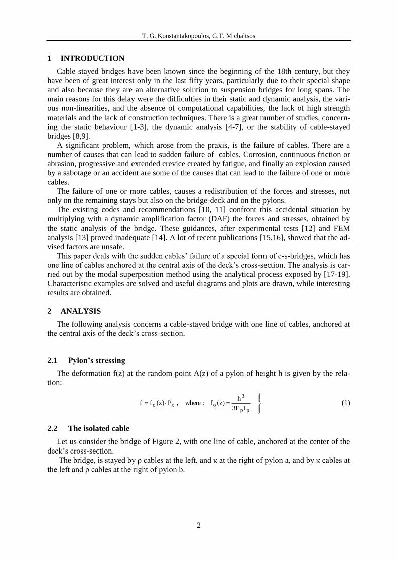
2.1 Pylon’s stressing
The deformation f(z) at the random point A(z) of a pylon of height h is given by the rela-
tion:
pp
3
oxoIE3
h)z(f:where,P)z(ff (1)
2.2 The isolated cable
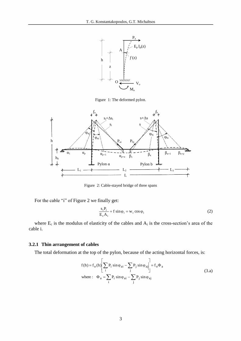
Let us consider the bridge of Figure 2, with one line of cable, anchored at the center of the
deck’s cross-section.
The bridge, is stayed by ρ cables at the left, and κ at the right of pylon a, and by κ cables at
the left and ρ cables at the right of pylon b.
T. G. Konstantakopoulos, G.T. Michaltsos
3
Figure 1: The deformed pylon.
Pylon α
αρ+κ αρ+1
αρ α1 βκ+1 βκ β1
βκ+ρ
fα fb
φαj
φαi
Pαi Pbj
φbj φbi
h
h0
Pylon b
L1 L2 L3
L
si+Δsi
si
s+Δs
s
Figure 2: Cable-stayed bridge of three spans
For the cable “i” of Figure 2 we finally get:
iiiic
ii coswsinfAE
Ps (2)
where Ec is the modulus of elasticity of the cables and Ai is the cross-section’s area of the
cable i.
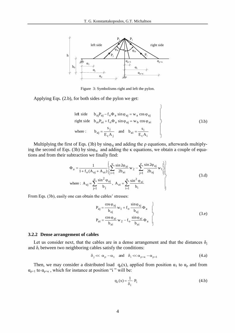
3.2.1 Thin arrangement of cables
The total deformation at the top of the pylon, because of the acting horizontal forces, is:
j
ajj
i
aiia
ao
j
ajj
i
aiio
sinPsinP:where
fsinPsinP)h(f)h(f
(3.a)
h
z
f (z)
A Ep Ip(z)
O Vο
Mο
Px
T. G. Konstantakopoulos, G.T. Michaltsos
4
Figure 3: Symbolisms right and left the pylon.
Applying Eqs. (2.b), for both sides of the pylon we get:
ic
iai
jc
jaj
aibajaoaiai
ajaajaoajaj
AE
sband
AE
sb:where
coswsinfPbsideright
coswsinfPbsideleft
(3.b)
Multiplying the first of Eqs. (3b) by sinφaj and adding the ρ equations, afterwards multiply-
ing the second of Eqs. (3b) by sinφai and adding the κ equations, we obtain a couple of equa-
tions and from their subtraction we finally find:
1i i
ai2
ai
1j j
aj2
aj
1j
1aj
aj
1i
2ai
ai
aiajoa
b
sinA,
b
sinA:where
wb2
2sinw
b2
2sin
)AA(f1
1
(3.d)
From Eqs. (3b), easily one can obtain the cables’ stresses:
aai
aio2
ai
aiai
aaj
ajo1
aj
ajaj
b
sinfw
b
cosP
b
sinfw
b
cosP
(3.e)
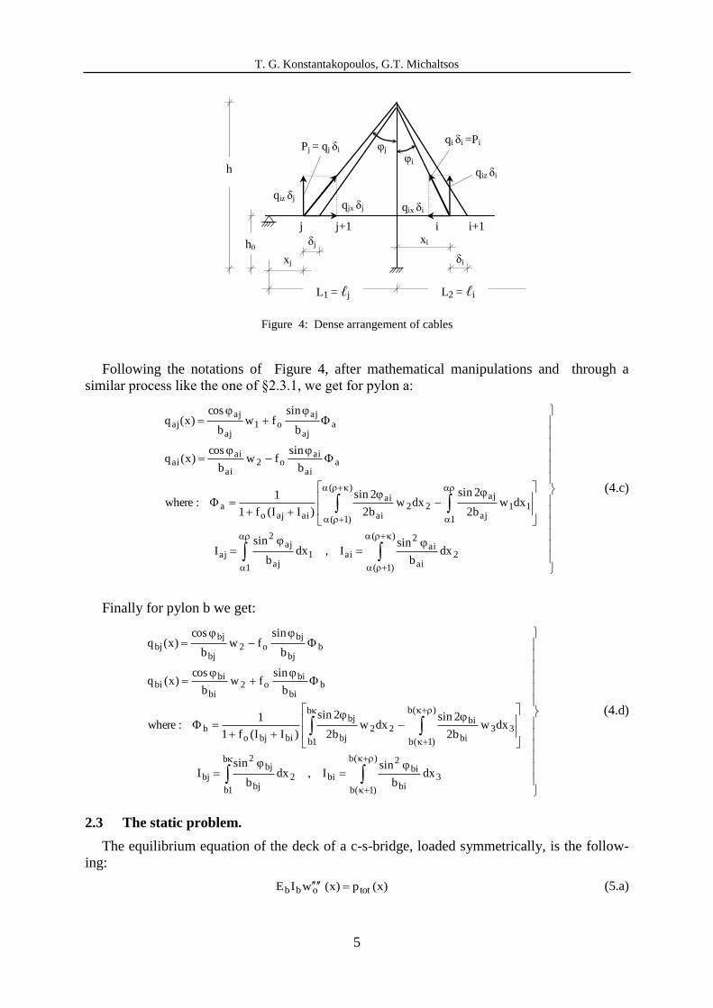
3.2.2 Dense arrangement of cables
Let us consider next, that the cables are in a dense arrangement and that the distances δj
and δi between two neighboring cables satisfy the conditions:
1i1j and (4.a)
Then, we may consider a distributed load qz(x), applied from position α1 to αρ and from
αρ+1 to αρ+κ , which for instance at position “i ” will be:
ii
i P1
)x(q
(4.b)
h
h0
α1
αρ
αj
αi
αρ+1
αρ+κ
φai
φaj
αρ+κ
left side right side
Pi Pj
Pj Pi
T. G. Konstantakopoulos, G.T. Michaltsos
5
Figure 4: Dense arrangement of cables
Following the notations of Figure 4, after mathematical manipulations and through a
similar process like the one of §2.3.1, we get for pylon a:
)(
)1(
2ai
ai2
ai
1
1aj
aj2
aj
1
11aj
aj)(
)1(
22ai
ai
aiajoa
aai
aio2
ai
aiai
aaj
ajo1
aj
ajaj
dxb
sinI,dx
b
sinI
dxwb2
2sindxw
b2
2sin
)II(f1
1:where
b
sinfw
b
cos)x(q
b
sinfw
b
cos)x(q
(4.c)
Finally for pylon b we get:
)(b
)1(b
3bi
bi2
bi
b
1b
2bj
bj2
bj
)(b
)1(b
33bi
bib
1b
22bj
bj
bibjob
bbi
bio2
bi
bibi
bbj
bjo2
bj
bjbj
dxb
sinI,dx
b
sinI
dxwb2
2sindxw
b2
2sin
)II(f1
1:where
b
sinfw
b
cos)x(q
b
sinfw
b
cos)x(q
(4.d)
2.3 The static problem.
The equilibrium equation of the deck of a c-s-bridge, loaded symmetrically, is the follow-
ing:
)x(p)x(wIE totobb (5.a)
j
φi
φj Pj = qj δi
h
h0
qiz δj
qiz δi
qi δi =Pi
j+1
qjx δj
L1 = ℓj L2 = ℓi
i i+1
xj
δj xi
δi
qix δi
T. G. Konstantakopoulos, G.T. Michaltsos
6
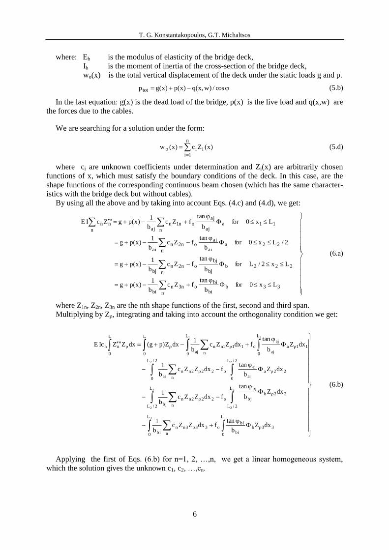
where: Eb is the modulus of elasticity of the bridge deck,
Ib is the moment of inertia of the cross-section of the bridge deck,
wo(x) is the total vertical displacement of the deck under the static loads g and p.
cos/)w,x(q)x(p)x(gp tot (5.b)
In the last equation: g(x) is the dead load of the bridge, p(x) is the live load and q(x,w) are
the forces due to the cables.
We are searching for a solution under the form:
n
1iiio )x(Zc)x(w (5.d)
where ci are unknown coefficients under determination and Zi(x) are arbitrarily chosen
functions of x, which must satisfy the boundary conditions of the deck. In this case, are the
shape functions of the corresponding continuous beam chosen (which has the same character-
istics with the bridge deck but without cables).
By using all the above and by taking into account Eqs. (4.c) and (4.d), we get:
33bbi
bio
n
n3nbi
222bbj
bjo
n
n2nbj
22aai
aio
n
n2nai
11aaj
ajo
n
n1najn
nn
Lx0forb
tanfZc
b
1)x(pg
Lx2/Lforb
tanfZc
b
1)x(pg
2/Lx0forb
tanfZc
b
1)x(pg
Lx0forb
tanfZc
b
1)x(pgZcIE
(6.a)
where Z1n, Z2n, Z3n are the nth shape functions of the first, second and third span.
Multiplying by Zρ, integrating and taking into account the orthogonality condition we get:
33
2
2
2
2
22
11
L
0
33bbi
bio
L
0
3
n
33nnbi
L
2/L
22bbj
bj
o
L
2/L
2
n
22nnbj
2/L
0
22aai
aio
2/L
0
2
n
22nnai
L
0
11aaj
aj
o
L
0
1
n
11nnaj
L
0
L
0
nn
dxZb
tanfdxZZc
b
1
dxZb
tan
fdxZZcb
1
dxZb
tanfdxZZc
b
1
dxZb
tanfdxZZc
b
1dxZ)pg(dxZZIcE
(6.b)
Applying the first of Eqs. (6.b) for n=1, 2, …,n, we get a linear homogeneous system,
which the solution gives the unknown c1, c2, …,cn.
T. G. Konstantakopoulos, G.T. Michaltsos
7
n,,3,2,1n:and
dxZcb2
2sindxZc
b2
2sin
)II(f1
1
dxZcb2
2sindxZc
b2
2sin
)II(f1
1:where
b
b
3
n
3nnbi
bi
b
b
2
n
2nnbj
bj
bibjob
a
a
a
a
1
n
1nnaj
aj
2
n
2nnai
ai
aiajoa
11
1 1
(6.c)
2.4 The dynamic characteristics of the bridge.
The equation of motion of a free vibrating bridge is:
sy q)t,x(wm)t,x(wc)t,x(wEJ (7.a)
We are searching for a solution of separate variables under the form:
)t(T)x(Z)t,x(w (7.b)
And through the well known process we get the following equations:
y
2424
scy JE
m:where,0TT
m
cT,0Z)x(q)x(q
EJ
1Z (7.c)
In order for us to apply the Galerkin’s procedure, we set:
)x(c)x(c)x(c)x(Z nn2211 (7.d)
where ci are unknown coefficients, under determination, and Ψi(x) are functions of x arbi-
trarily chosen, that satisfy the boundary conditions, of the static system of bridge-deck. As
such functions we choose the shape functions of the corresponding static system of beam-
deck (a continuous beam or a set of three single-span beams) that has the same characteristics
with the bridge-deck without cables.
Introducing Eq. (7d) into (7a), multiplying the out coming successively by Ψ1, Ψ2, ....,Ψn
and integrating the results from 0 to L, we obtain the following homogeneous, linear system,
without second member of n equations, wit unknowns c1, c2, …., cn :
n,....,2,1iwith,0)BA(c)BA(c)BA(c in4
inn2i4
2i21i4
1i1 (7.e)
where:
L
0
jiij
L
0
ijsy
jij dxB,dx)(qJE
1A (7.f)
In order for the above system to have non-trivial solutions, the determinant of its coeffi-
cients must be zero:
ij4
ijijij BAandn,,2,1j,iwith0 (7.g)
From Eq. (7g), we determine the values of λ and from Eq. (7c) the spectrum of the flex-
ural eigenfrequencies ωi. From the first (n-1) equations of the system (7e), we can find:
T. G. Konstantakopoulos, G.T. Michaltsos
8
n
2j
j1
j11n
ij
n)1n()1j)(1n(1)1n()1j)(1n(2)1n(
n2)1j(221)1j(222
n1)1j(111)1j(112
1
j
)c
c(c)x(Z:thereforeand
n,,2,1j)1n(,,2,1iwith
c
c
(7.h)
where Xn(x) are the shape functions of the bridge with combined cable system.
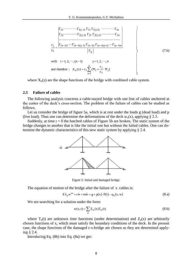
2.5 Failure of cables
The following analysis concerns a cable-stayed bridge with one line of cables anchored at
the center of the deck’s cross-section. The problem of the failure of cables can be studied as
follows.
Let us consider the bridge of figure 5a, which is at rest under the loads g (dead load) and p
(live load). Thus one can determine the deformations of the deck wo(x), applying § 2.3.
Suddenly, at time t = 0 the hatched cables of Figure 5b are broken. The static system of the
bridge changes to another that is like the initial one but without the failed cables. One can de-
termine the dynamic characteristics of this new static system by applying § 2.4.
Figure 5: Initial and damaged bridge.
The equation of motion of the bridge after the failure of s cables is:
)w,x(q)t(P)x(pgwmwcwIE sy (8.a)
We are searching for a solution under the form:
n
nn )t(T)x(Z)t,x(w (8.b)
where Tn(t) are unknown time functions (under determination) and Zn(x) are arbitrarily
chosen functions of x, which must satisfy the boundary conditions of the deck. In the present
case, the shape functions of the damaged c-s-bridge are chosen as they are determined apply-
ing § 2.4.
Introducing Eq. (8b) into Eq. (8a) we get:
a)
b)
T. G. Konstantakopoulos, G.T. Michaltsos
9
)t(P)x(pg)TZ,x(qTZmTZcTZIE
n
nns
n
nn
n
nnn
n
ny (8.c)
Remembering that Zn satisfies the equation of the free motion of the wounded bridge:
0)TZ,x(qTZmTZIE
n
nns
n
nn2nn
n
ny (8.d)
the above Eq. (8c) becomes:
)t(P)x(pgTZmTZcTZm
n
nn2n
n
nn
n
nn (9.a)
Multiplying the above by Zk, integrating from 0 to L and remembering the orthogonality
condition, we finally obtain:
L
0
k
L
0
k
L
0
2k
k2kkk
dxZ)x(p)t(PdxZg)t(G:where
)t(G
dxZm
1TT
m
cT
(9.b)
The solution of the above is given by the Duhamel integral:
22kk
t
0
k)t(
L
0
2kk
k
,m2
c:where
d)]t(sin[)(Ge
dxZm
1)t(T
(9.c)
Therefore the general solution of Eq. (7.b) is given by:
n
nnnnt
n )t(T)tcosBtsinAn(eZ)t,x(w (9.d)
The constants An and Bn are determined from the time conditions
0)t,x(wand)x(w)t,x(w ooo as follows:
L
0
2n
t
L
0
no
nn
nnn
dxZe
dxZ)x(w
B,)0(TB
A
o
(9.e)
3 NUMERICAL RESULTS AND DISCUSSION
In order to study the influence of the sudden failure of cables on the bridge’s behavior
and static adequacy, we consider a bridge with the following data: L1=150m, L2=350m,
L3=150m, g=7000dN/m, (m=700 gr*/m), Ib=0.50m
4, IP=1000Ib, α1=20m, αρ=130m, αρ+1=30m,
αρ+κ=170m, β1=180m, βκ=320m, βκ+1=20m, βκ+ρ=130m, and live load p=7000dN/m. The dis-
tance between two neighboring cables is 5 m. The following five cases are studied: The non
damaged bridge, a bridge under the sudden failure of 15 cables, a bridge under the sudden
T. G. Konstantakopoulos, G.T. Michaltsos
10
failure of 10 cables, a bridge under the sudden failure of 5 cables, a bridge under the sudden
failure of 1 cable. Due to the restricted length of this paper the plots of the cases of the bridge
under the sudden failure of 15 cables, 10 cables, 5 cables and 1 cable do not shown in this pa-
per but they will be included in the presentation at the conference.
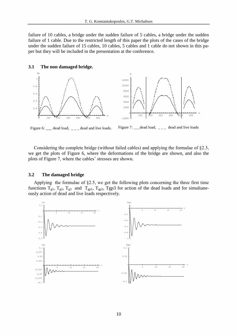
3.1 The non damaged bridge.
100 200 300 400 500 600
x
0.2
0.4
0.6
0.8
1
Wo
Figure 6: ___ dead load, _ _ _ dead and live loads.
100 200 300 400 500 600
x
-2000
2000
4000
6000
8000
10000
12000
g
Figure 7: ___dead load, _ _ _ dead and live loads
Considering the complete bridge (without failed cables) and applying the formulae of §2.3,
we get the plots of Figure 6, where the deformations of the bridge are shown, and also the
plots of Figure 7, where the cables’ stresses are shown.
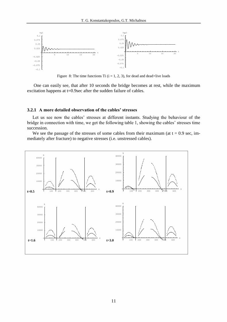
3.2 The damaged bridge
Applying the formulae of §2.5, we get the following plots concerning the three first time
functions Tg1, Tg2, Tg3 and Tgp1, Tgp2, Tgp3 for action of the dead loads and for simultane-
ously action of dead and live loads respectively.
5 10 15 20
t
-0.5
-0.4
-0.3
-0.2
-0.1
0.1
Tg1
5 10 15 20
t
-1
-0.8
-0.6
-0.4
-0.2
Tgp1
5 10 15 20
t
-0.1
-0.075
-0.05
-0.025
0.025
0.05
0.075
0.1
Tg2
5 10 15 20
t
-0.1
-0.05
0.05
0.1
Tgp2
T. G. Konstantakopoulos, G.T. Michaltsos
11
5 10 15 20
t
-0.1
-0.075
-0.05
-0.025
0.025
0.05
0.075
0.1
Tg3
5 10 15 20
t
-0.1
-0.075
-0.05
-0.025
0.025
0.05
0.075
0.1
Tgp3
Figure 8: The time functions Ti (i = 1, 2, 3), for dead and dead+live loads
One can easily see, that after 10 seconds the bridge becomes at rest, while the maximum
excitation happens at t=0.9sec after the sudden failure of cables.
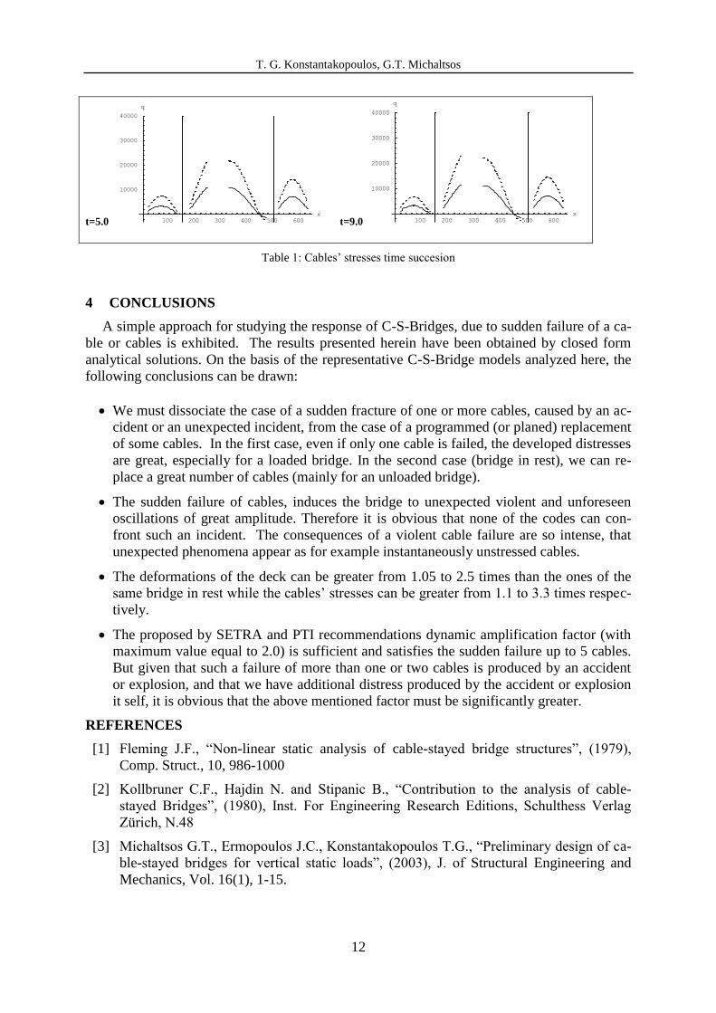
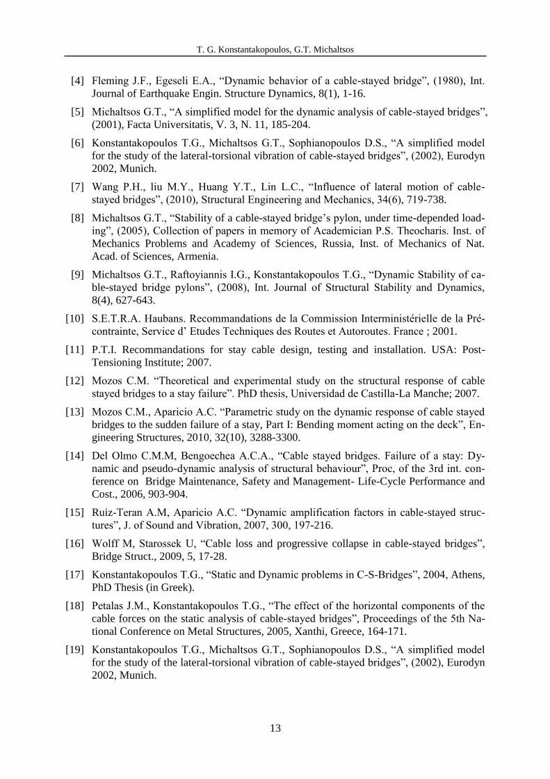
3.2.1 A more detailed observation of the cables’ stresses
Let us see now the cables’ stresses at different instants. Studying the behaviour of the
bridge in connection with time, we get the following table 1, showing the cables’ stresses time
succession.
We see the passage of the stresses of some cables from their maximum (at t = 0.9 sec, im-
mediately after fracture) to negative stresses (i.e. unstressed cables).
t=0.5 100 200 300 400 500 600
x
10000
20000
30000
40000
q
t=0.9 100 200 300 400 500 600
x
10000
20000
30000
40000
q
t=1.6 100 200 300 400 500 600
x
10000
20000
30000
40000
q
t=3.0 100 200 300 400 500 600
x
10000
20000
30000
40000
q
T. G. Konstantakopoulos, G.T. Michaltsos
12
t=5.0 100 200 300 400 500 600
x
10000
20000
30000
40000
q
t=9.0 100 200 300 400 500 600
x
10000
20000
30000
40000
q
Table 1: Cables’ stresses time succesion
4 CONCLUSIONS
A simple approach for studying the response of C-S-Bridges, due to sudden failure of a ca-
ble or cables is exhibited. The results presented herein have been obtained by closed form
analytical solutions. On the basis of the representative C-S-Bridge models analyzed here, the
following conclusions can be drawn:
We must dissociate the case of a sudden fracture of one or more cables, caused by an ac-
cident or an unexpected incident, from the case of a programmed (or planed) replacement
of some cables. In the first case, even if only one cable is failed, the developed distresses
are great, especially for a loaded bridge. In the second case (bridge in rest), we can re-
place a great number of cables (mainly for an unloaded bridge).
The sudden failure of cables, induces the bridge to unexpected violent and unforeseen
oscillations of great amplitude. Therefore it is obvious that none of the codes can con-
front such an incident. The consequences of a violent cable failure are so intense, that
unexpected phenomena appear as for example instantaneously unstressed cables.
The deformations of the deck can be greater from 1.05 to 2.5 times than the ones of the
same bridge in rest while the cables’ stresses can be greater from 1.1 to 3.3 times respec-
tively.
The proposed by SETRA and PTI recommendations dynamic amplification factor (with
maximum value equal to 2.0) is sufficient and satisfies the sudden failure up to 5 cables.
But given that such a failure of more than one or two cables is produced by an accident
or explosion, and that we have additional distress produced by the accident or explosion
it self, it is obvious that the above mentioned factor must be significantly greater.
REFERENCES
[1] Fleming J.F., “Non-linear static analysis of cable-stayed bridge structures”, (1979),
Comp. Struct., 10, 986-1000
[2] Kollbruner C.F., Hajdin N. and Stipanic B., “Contribution to the analysis of cable-
stayed Bridges”, (1980), Inst. For Engineering Research Editions, Schulthess Verlag
Zürich, N.48
[3] Michaltsos G.T., Ermopoulos J.C., Konstantakopoulos T.G., “Preliminary design of ca-
ble-stayed bridges for vertical static loads”, (2003), J. of Structural Engineering and
Mechanics, Vol. 16(1), 1-15.
T. G. Konstantakopoulos, G.T. Michaltsos
13
[4] Fleming J.F., Egeseli E.A., “Dynamic behavior of a cable-stayed bridge”, (1980), Int.
Journal of Earthquake Engin. Structure Dynamics, 8(1), 1-16.
[5] Michaltsos G.T., “A simplified model for the dynamic analysis of cable-stayed bridges”,
(2001), Facta Universitatis, V. 3, N. 11, 185-204.
[6] Konstantakopoulos T.G., Michaltsos G.T., Sophianopoulos D.S., “A simplified model
for the study of the lateral-torsional vibration of cable-stayed bridges”, (2002), Eurodyn
2002, Munich.
[7] Wang P.H., liu M.Y., Huang Y.T., Lin L.C., “Influence of lateral motion of cable-
stayed bridges”, (2010), Structural Engineering and Mechanics, 34(6), 719-738.
[8] Michaltsos G.T., “Stability of a cable-stayed bridge’s pylon, under time-depended load-
ing”, (2005), Collection of papers in memory of Academician P.S. Theocharis. Inst. of
Mechanics Problems and Academy of Sciences, Russia, Inst. of Mechanics of Nat.
Acad. of Sciences, Armenia.
[9] Michaltsos G.T., Raftoyiannis I.G., Konstantakopoulos T.G., “Dynamic Stability of ca-
ble-stayed bridge pylons”, (2008), Int. Journal of Structural Stability and Dynamics,
8(4), 627-643.
[10] S.E.T.R.A. Haubans. Recommandations de la Commission Interministérielle de la Pré-
contrainte, Service d’ Etudes Techniques des Routes et Autoroutes. France ; 2001.
[11] P.T.I. Recommandations for stay cable design, testing and installation. USA: Post-
Tensioning Institute; 2007.
[12] Mozos C.M. “Theoretical and experimental study on the structural response of cable
stayed bridges to a stay failure”. PhD thesis, Universidad de Castilla-La Manche; 2007.
[13] Mozos C.M., Aparicio A.C. “Parametric study on the dynamic response of cable stayed
bridges to the sudden failure of a stay, Part I: Bending moment acting on the deck”, En-
gineering Structures, 2010, 32(10), 3288-3300.
[14] Del Olmo C.M.M, Bengoechea A.C.A., “Cable stayed bridges. Failure of a stay: Dy-
namic and pseudo-dynamic analysis of structural behaviour”, Proc, of the 3rd int. con-
ference on Bridge Maintenance, Safety and Management- Life-Cycle Performance and
Cost., 2006, 903-904.
[15] Ruiz-Teran A.M, Aparicio A.C. “Dynamic amplification factors in cable-stayed struc-
tures”, J. of Sound and Vibration, 2007, 300, 197-216.
[16] Wolff M, Starossek U, “Cable loss and progressive collapse in cable-stayed bridges”,
Bridge Struct., 2009, 5, 17-28.
[17] Konstantakopoulos T.G., “Static and Dynamic problems in C-S-Bridges”, 2004, Athens,
PhD Thesis (in Greek).
[18] Petalas J.M., Konstantakopoulos T.G., “The effect of the horizontal components of the
cable forces on the static analysis of cable-stayed bridges”, Proceedings of the 5th Na-
tional Conference on Metal Structures, 2005, Xanthi, Greece, 164-171.
[19] Konstantakopoulos T.G., Michaltsos G.T., Sophianopoulos D.S., “A simplified model
for the study of the lateral-torsional vibration of cable-stayed bridges”, (2002), Eurodyn
2002, Munich.
Recommended