[ 3 3 4 ]
A NEW MICRO-RESPIROMETER WITH AUTOMATICSETTING AND RECORDING APPARATUS
BY PETER TUFTFrom the Department of Zoology, University of Cambridge
{Received 21 April 1950)
(With Plate 11 and Ten Text-figures)
The instrument was designed to measure the O2 uptake of living material whichconsumes between o-oi and 5-0 yl. O2/ hr. Its accuracy is +o-ooi /u.1., and it hasthe following advantages over other micro-respirometers of similar sensitivity.
(a) It is robust, easy to handle and is suitable for routine use.(b) The respirometer constant is independent of the gas volume of the reaction
vessel.(c) Its sensitivity is independent of the volume of the reaction vessel, and it can
therefore be used with relatively large amounts of living material.(d) Experiments can be carried out over a wide range of temperatures without
appreciably altering the accuracy.(e) It can be coupled to apparatus (described at the end of this paper), which
automatically measures and records the rate of O2 uptake.A comprehensive review of the better known micro-respirometers has been given
by Tobias (1943), but to facilitate comparison with the present instrument a list ofthe characteristics of some of them are given in Table 1.
Table 1. The characteristics of different types of micro-respirometer
Barcroft WarburgSteffanelli (1937)Cartesian diver
(i) Linderstrom-Lang & Holter (1943)(2) Zeuthen (1943)
The new instrument
Sensitivity(smallest ratethat can bemeasured)(^il./hr.)
1 0
0-06
O'OIO-OO2O'OI
Accuracy
±0-5±0-003
+ 0-0002+ O-OOOO2+ O-00I
Volume ofthe reaction
500030-100
1 0o-i
50-100
PRINCIPLE
The principle of the instrument can best be followed from the diagram (Text-fig. 1).It consists essentially of two vessels—a reaction vessel and a compensating vessel—connected by a U-tube containing a drop of kerosene. The volume of the reactionvessel can be adjusted at will by means of a pipette. This consists of a mercury-filled reservoir from which known volumes of mercury can be displaced by means
Micro-respirometer with automatic setting and recording apparatus 335
of a metal plunger actuated by a screw micrometer (the latter is not shown inText-fig. 1). When the two vessels are cut off from the outside atmosphere, anypressure change in one relative to the other will be followed by a correspondingmovement of the kerosene droplet. In order to determine the amount of gas absorbedor evolved by the experimental material, the two vessels are set up so that they differonly in the single respect that one—the reaction vessel—contains the material to bestudied. The respirometer is placed in a water-bath, and after a suitable equilibrationperiod the outlet valves are closed. After a short time the movement of the kerosenewill represent changes in pressure due to the experimental material. The volume ofthe reaction vessel is then adjusted with the pipette until the kerosene meniscus is
Metal plungeractuated by a
screw micrometer
Mercuryreservoir
Kerosene
Text-fig. 1. Diagram to show principle of the micro-respirometer.
brought level with a fixed point on the U-tube. After a known interval the meniscusis again adjusted to the same point; the gas pressure of the whole system is therebyrestored to its original value. The volume of the length of plunger introduced orwithdrawn from the reservoir is equal to the volume of gas absorbed or evolved inthe reaction vessel, at the temperature and pressure of the experiment.
GENERAL DESCRIPTION OF THE MICRO-RESPIROMETER
The manometer component (Text-fig. 2) and the pipette (Text-fig. 3) are describedseparately. The assembled instrument is shown in PI. 11, fig. 2.
(i) The manometer component (Text-fig. 2)
The reaction vessel and the compensating vessel (Text-fig. zA) are both detachable,and consist of small glass cups, with ground edges (which are greased). Bothvessels are clamped on to a stainless steel block (Text-fig. zC) by means of twothumb screws (Text-fig. zD). Sealed into the block and opening into the cavity
336 PETER T U F T
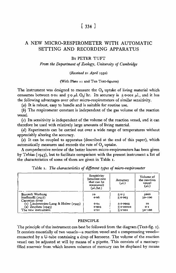
under each vessel, is a small, fine-bore capillary U-tube (Text-fig. 2E), containinga drop of kerosene. The meniscus of the kerosene (Text-fig. 2F) is observed througha low-powered microscope (Text-fig. 4). A glass capillary (Text-fig. zG), of slightlylarger bore, connects the reaction vessel and the reservoir of the pipette (Text-fig. 2H).
1 in.
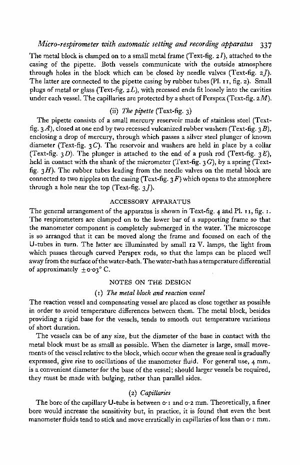
Text-fig. 2. Text-fig. 3.Text-fig. 2. The manometer component. A, reaction vessel; B, compensating vessel; C, stainless
steel block; D, clamping screw; E, U-tube; F, kerosene meniscus; G, pipette capillary;H, mercury reservoir; / , metal frame; J, needle valves; K, nipple for outlet tube; L, recessedmetal plugs for experimental material; M, Perspex plate; N, needle; P, spring.
Text-fig. 3. The pipette component. A, mercury reservoir; B, vulcanized rubber washers, withrecess for Hg seal; C, silver steel plurtger; D, screw collar; E, push rod; F, nipples for outlettubes; G, micrometer; H, spring; /, pipette casing; J, outlet; K, position of metal frame to holdmanometer.
Micro-respirometer with automatic setting and recording apparatus 337
The metal block is clamped on to a small metal frame (Text-fig. 21), attached to thecasing of the pipette. Both vessels communicate with the outside atmospherethrough holes in the block which can be closed by needle valves (Text-fig. zj).The latter are connected to the pipette casing by rubber tubes (PI. 11, fig. 2). Smallplugs of metal or glass (Text-fig. zL), with recessed ends fit loosely into the cavitiesunder each vessel. The capillaries are protected by a sheet of Perspex (Text-fig. zM).
(ii) The pipette (Text-fig. 3)The pipette consists of a small mercury reservoir made of stainless steel (Text-
fig. 3 A), closed at one end by two recessed vulcanized rubber washers (Text-fig. 3 B),enclosing a drop of mercury, through which passes a silver steel plunger of knowndiameter (Text-fig. 3 C). The reservoir and washers are held in place by a collar(Text-fig. 3D). The plunger is attached to the end of a push rod (Text-fig. 3Z?),held in contact with the shank of the micrometer (Text-fig. 3 G), by a spring (Text-fig. 3#) . The rubber tubes leading from the needle valves on the metal block areconnected to two nipples on the casing (Text-fig. 3 F) which opens to the atmospherethrough a hole near the top (Text-fig. 3/).
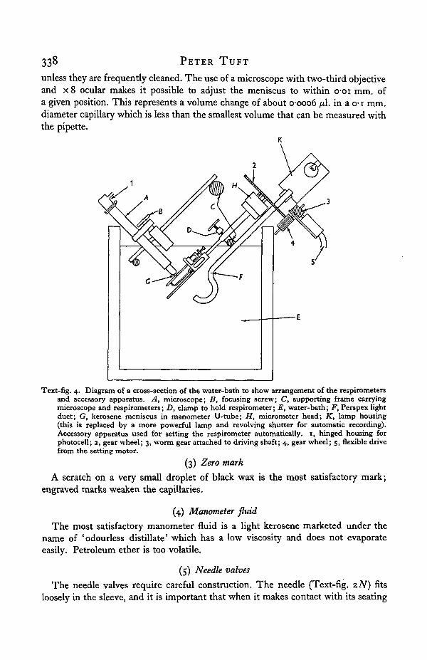
ACCESSORY APPARATUSThe general arrangement of the apparatus is shown in Text-fig. 4 and PI. 11, fig. 1.The respirometers are clamped on to the lower bar of a supporting frame so thatthe manometer component is completely submerged in the water. The microscopeis so arranged that it can be moved along the frame and focused on each of theU-tubes in turn. The latter are illuminated by small 12 V. lamps, the light fromwhich passes through curved Perspex rods, so that the lamps can be placed wellaway from the surface of the water-bath. The water-bath has a temperature differentialof approximately + 0-03° C.
NOTES ON THE DESIGN
(1) The metal block and reaction vessel
The reaction vessel and compensating vessel are placed as close together as possiblein order to avoid temperature differences between them. The metal block, besidesproviding a rigid base for the vessels, tends to smooth out temperature variationsof short duration.
The vessels can be of any size, but the diameter of the base in contact with themetal block must be as small as possible. When the diameter is large, small move-ments of the vessel relative to the block, which occur when the grease seal is graduallyexpressed, give rise to oscillations of the manometer fluid. For general use, 4 mm.is a convenient diameter for the base of the vessel; should larger vessels be required,they must be made with bulging, rather than parallel sides.
(2) Capillaries
The bore of the capillary U-tube is between o-i and 0-2 mm. Theoretically, a finerbore would increase the sensitivity but, in practice, it is found that even the bestmanometer fluids tend to stick and move erratically in capillaries of less than o-1 mm.
PETER T U F T
unless they are frequently cleaned. The use of a microscope with two-third objectiveand x 8 ocular makes it possible to adjust the meniscus to within o-oi mm. ofa given position. This represents a volume change of about o-ooo6 /*1. in a o-1 mm.diameter capillary which is less than the smallest volume that can be measured withthe pipette.
K
Text-fig. 4. Diagram of a cross-section of the water-bath to show arrangement of the respirometersand accessory apparatus. A, microscope; B, focusing screw; C, supporting frame carryingmicroscope and respirometers; D, clamp to hold respirometer; E, water-bath; F, Perspex lightduct; G, kerosene meniscus in manometer U-tube; H, micrometer head; K, lamp housing(this is replaced by a more powerful lamp and revolving shutter for automatic recording).Accessory apparatus used for setting the respirometer automatically. 1, hinged housing forphotocell; 2, gear wheel; 3, worm gear attached to driving shaft; 4, gear wheel; 5, flexible drivefrom the setting motor.
(3) Zero mark
A scratch on a very small droplet of black wax is the most satisfactory mark;engraved marks weaken the capillaries.
(4) Manometer fluid
The most satisfactory manometer fluid is a light kerosene marketed under thename of 'odourless distillate' which has a low viscosity and does not evaporateeasily. Petroleum ether is too volatile.
(5) Needle valves
The needle valves require careful construction. The needle (Text-fig. 2iV) fitsloosely in the sleeve, and it is important that when it makes contact with its seating
Micro-respirometer with automatic setting and recording apparatus 339
it should come to rest. (The needles are allowed to make their own seating and arenot ground in.) Before the instrument is assembled the valves are tested witha vacuum pump. A properly constructed valve should hold a vacuum of 3 mm.mercury for over an hour, but it is sometimes necessary to grease the needle lightlybefore it will pass this test.
(6) Pipette
The pipette is the central support of the instrument. It is larger than the rest ofthe respirometer, but only the mercury contained in the reservoir is liable to giverise to errors when the temperature varies. These errors, however, are not importantif the volume of mercury does not exceed 10 /xl. No error is introduced by thethermal expansion of the metal push rod because it is compensated by a corre-sponding expansion of the metal casing of the pipette.
(7) Pipette plunger
The terminal half inch of the plunger, which is used to displace mercury in thereservoir, must have a uniform diameter. The smallest diameter that can be usedconveniently is •£$ in. because smaller plungers bend and give rise to inaccuracies. Theaccuracy of the pipette depends on the accuracy with which the plunger displacesthe mercury, for this reason the mercury in the reservoir must be free of air bubbles.Their presence can be detected by applying a vacuum to the end of the pipettecapillary and observing the Hg meniscus.
EXPERIMENTAL PROCEDURE
(1) Equilibration
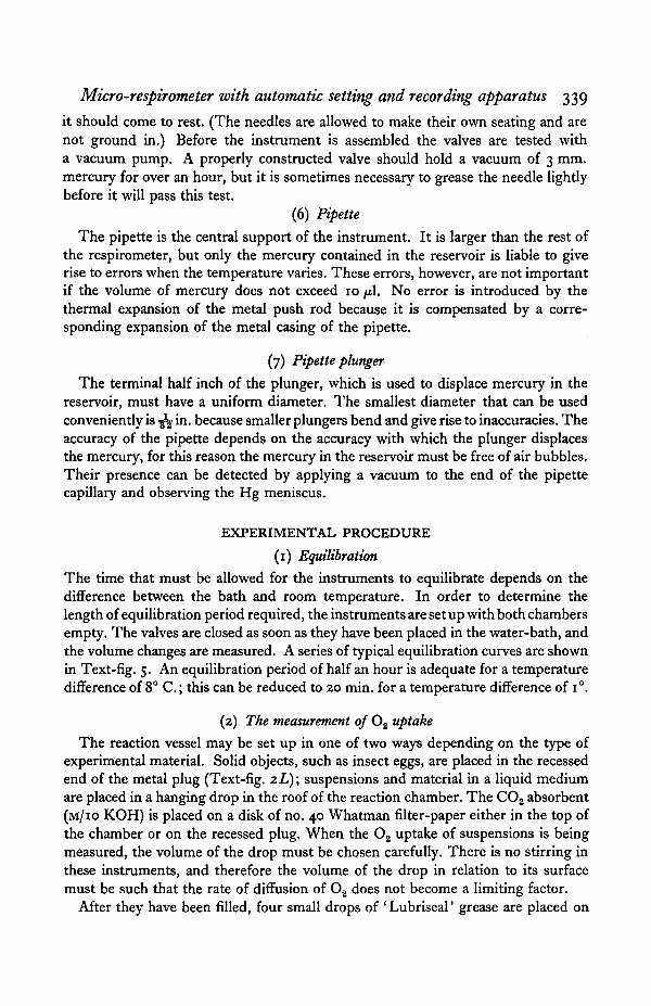
The time that must be allowed for the instruments to equilibrate depends on thedifference between the bath and room temperature. In order to determine thelength of equilibration period required, the instruments are set up with both chambersempty. The valves are closed as soon as they have been placed in the water-bath, andthe volume changes are measured. A series of typical equilibration curves are shownin Text-fig. 5. An equilibration period of half an hour is adequate for a temperaturedifference of 8° C.; this can be reduced to 20 min. for a temperature difference of i°.
(2) The measurement of O2 uptake
The reaction vessel may be set up in one of two ways depending on the type ofexperimental material. Solid objects, such as insect eggs, are placed in the recessedend of the metal plug (Text-fig. 2L); suspensions and material in a liquid mediumare placed in a hanging drop in the roof of the reaction chamber. The CO2 absorbent(M/IO KOH) is placed on a disk of no. 40 Whatman filter-paper either in the top ofthe chamber or on the recessed plug. When the O2 uptake of suspensions is beingmeasured, the volume of the drop must be chosen carefully. There is no stirring inthese instruments, and therefore the volume of the drop in relation to its surfacemust be such that the rate of diffusion of O2 does not become a limiting factor.
After they have been filled, four small drops of 'Lubriseal' grease are placed on
340 PETER TUFT
the ground surfaces of the vessels, and they are then clamped on to the metal blockwith the thumb screws. The instrument is placed in the water-bath. The rubbertubes attached to the needle valves are gently squeezed to make sure the capillariesare not blocked. After an appropriate equilibration period, the valves are closedand tested by bending and squeezing the rubber tubes. Five minutes later themeniscus is adjusted to the zero point on the U-tube. This adjustment is repeatedat intervals. The actual volume changes are obtained by multiplying the differencebetween successive readings of the micrometer by the volume per unit length of theplunger. A series of respiration experiments are described in Appendix I.
005
0-04
003
002
u 0-01
o
-001
- 0 0 245 60
Time (min.)90
Text-fig. 5. A series of equilibration curves. Room temperature, 170 C ,bath temperature, 250 C.
(3) Gas mixtures
The vessels can be filled with any desired gas mixture, but the plugs whichnormally hold the experimental material cannot be used. If a holder is required itmust have a hole down the centre so that the gas mixture can reach the upper partof the chamber.
The vessels are greased and placed in position but are not clamped down; so thatthe gas can escape between the droplets of grease. The gas supply is connected tothe rubber tube attached to the needle valve.
When the gas has been turned on the kerosene droplet is observed to ensure thatan adequate pressure is maintained in the vessel, and to assist ventilation the micro-meter is screwed up and down at intervals. The gas supply is then disconnected; thechambers are clamped down on to the block and the needle valves are closed.
Micro-respirotneter with automatic setting and recording apparatus 341
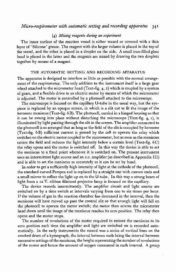
(4) Mixing reagents during an experiment
The inner surface of the reaction vessel is either waxed or covered with a thinlayer of' Silicone' grease. The reagent with the larger volume is placed in the top ofthe vessel, and the other is placed in a droplet on the side. A small iron-filled glassbead is placed in the latter and the reagents are mixed by drawing the two dropletstogether by means of a magnet.
THE AUTOMATIC SETTING AND RECORDING APPARATUS
The apparatus is designed to interfere as little as possible with the normal arrange-ment of the respirometer. The only addition to the instrument itself is a large gearwheel attached to the micrometer head (Text-fig. 4, 2) which is coupled by a systemof gears, and a flexible drive to an electric motor by means of which the micrometeris adjusted. The motor is controlled by a photocell attached to the microscope.
The microscope is focused on the capillary U-tube in the usual way, but the eye-piece is replaced by an opaque screen, in which is a slit cut to fit the image of thekerosene meniscus (Text-fig. 6B). The photocell, carried in a hinged housing so thatit can be swung into place without disturbing the microscope (Text-fig. 4, 1), isilluminated by light passing through the slit in the screen. The amplifier connected tothe photocell is so arranged that as long as the field of the slit is occupied by kerosene(Text-fig. 6B) sufficient current is passed by the cell to operate the relay whichswitches on the electric motor coupled to the micrometer, but as soon as the meniscusenters the field and reduces the light intensity below a certain level (Text-fig. 6C)the relay opens and the motor is switched off. In this way the device is able to setthe meniscus to a fixed point whenever it is switched on. The present instrumentuses an intermittent light source and an a.c. amplifier (as described in Appendix III)and is able to set the meniscus as accurately as it can be set by hand.
In order to get a sufficiently high intensity of light at the cathode of the photocell,the standard curved Perspex rod is replaced by a straight one with convex ends anda small mirror to reflect the light up on to the U-tube. In this way a strong beam oflight from a 12 V. ribbon filament projector lamp is focused on the capillary.
The device records intermittently. The amplifier circuit and light source areswitched on by a time switch at intervals varying from one to six times per hour.If the volume of gas in the reaction chamber has decreased in the interval, then themeniscus will have moved up past the control slit so that enough light will fall onthe photocell to operate the motor switch; the motor then screws the micrometerhead down until the image of the meniscus reaches its zero position. The relay thenopens and the motor stops.
The number of revolutions of the motor required to restore the -meniscus to itszero position each time the amplifier and light are switched on is recorded auto-matically. In the early instruments the record was a series of vertical lines on thesmoked drum of a kymograph, the interval between each being the interval betweensuccessive settings of the meniscus, the height representing the number of revolutionsof the motor and hence the amount of oxygen consumed in each interval. A group
342 PETER T U F T
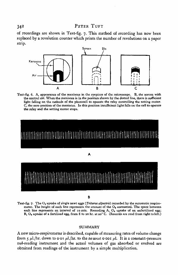
of recordings are shown in Text-fig. 7. This method of recording has now beenreplaced by a revolution counter which prints the number of revolutions on a paperstrip.
Screen Silt
A /kerosene
N
Air
-/PIN
Text-fig. 6. A, appearance of the meniscus in the eyepiece of the microscope. B, the screen withthe control slit. When the meniscus is in the position shown by the dotted line, there is sufficientlight falling on the cathode of the photocell to operate the relay controlling the setting motor.C, the zero position of the meniscus. In this position insufficient light falls on the cell to operatethe relay and the setting motor stops.
B
Text-fig. 7. The O, uptake of single newt eggs (Triturus alpestris) recorded by the automatic respiro-meter. The height of each line represents the amount of the Os consumed. The space betweeneach line represents an interval of 10 min. Recording A, Ot uptake of an unfertilized egg;B, Os uptake of a fertilized egg, from 8 to 20 hr. at 200 C. (Records are read from right to left.)
SUMMARY
A new micro-respirometer is described, capable of measuring rates of volume changefrom 5 /xl./hr. down to o-oi /il./hr. to the nearest o-ooi pi. It is a constant-pressurenul-reading instrument and the actual volumes of gas absorbed or evolved areobtained from readings of the instrument by a simple multiplication.

Micro-respirometer with automatic setting and recording apparatus 343
A device is described which sets the instrument automatically and records thevolume changes at regular intervals.
I wish to thank Prof. J. Gray, F.R.S., in whose department the instrument wasdeveloped, and also all those members of the staff who have helped me with thedesign and construction of the instrument, in particular Dr Ralph Brown. I shouldalso like to thank Mr S. Falloon of the Cavendish Laboratory for designing theamplifier which has made the automatic attachment possible, and Lord Rothschildfor helpful criticism of the manuscript.
The instrument was designed while I was receiving a research grant from theAgricultural Research Council, and The Royal Society kindly made a grant for theconstruction of the automatic attachment.
344 PETER TUFT
APPENDIX i
Experimental results
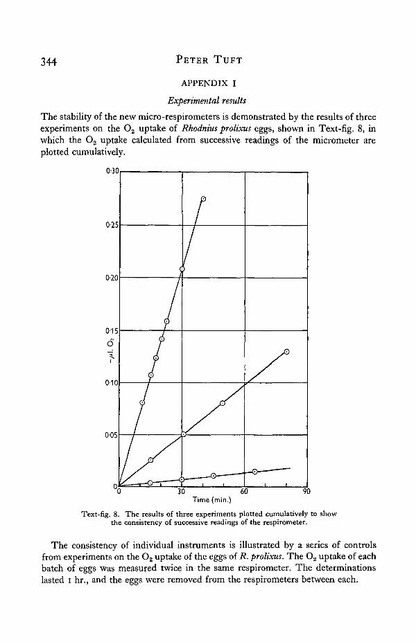
The stability of the new micro-respirometers is demonstrated by the results of threeexperiments on the O2 uptake of Rhodnius prolixus eggs, shown in Text-fig. 8, inwhich the O2 uptake calculated from successive readings of the micrometer areplotted cumulatively.
0-30
0-25
0-20
0-15
O
"5.i
0-10
0-05
Time (min.)
Text-fig. 8. The results of three experiments plotted cumulatively to showthe consistency of successive readings of the respirometer.
The consistency of individual instruments is illustrated by a series of controlsfrom experiments on the O2 uptake of the eggs of R. prolixus. The O2 uptake of eachbatch of eggs was measured twice in the same respirometer. The determinationslasted i hr., and the eggs were removed from the respirometers between each.
Micro-respirometer with automatic setting and recording apparatus 345
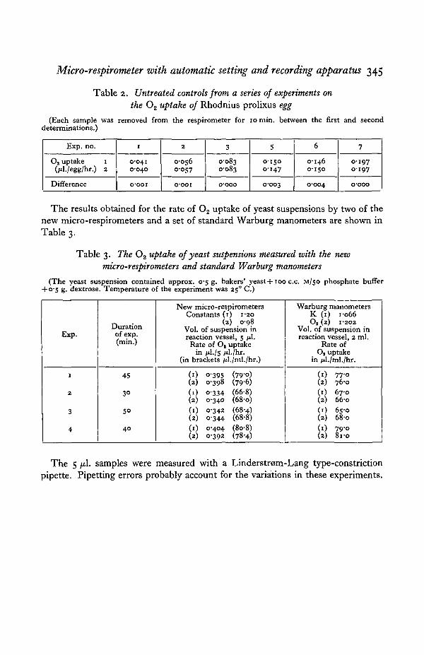
Table 2. Untreated controls from a series of experiments on
the 0 2 uptake of Rhodnius prolixus egg
(Each sample was removed from the respirometer for 10 min. between the first and seconddeterminations.)
Exp. no.
O2 uptake i(/il./egg/hr.) 2
Difference
1
0-0410-040
o-ooi
2
O-OS6O-O57
o-ooi
3
0-0830-083
o-ooo
5
0-1500-147
0-003
6
0-1460-150
0-004
7
0-1970197
o-ooo
The results obtained for the rate of O2 uptake of yeast suspensions by two of thenew micro-respirometers and a set of standard Warburg manometers are shown inTable 3.
Table 3. The O2 uptake of yeast suspensions measured with the new
micro-respirometers and standard Warburg manometers
(The yeast suspension contained approx. 0-5 g. bakers' yeast+100 c.c. M/50 phosphate buffer+ 0-5 g. dextrose. Temperature of the experiment was 250 C.)
Exp.
i
2
3
4
Durationof exp.(min.)
45
3°
5°
4 0
New micro-respirometersConstants (1) 1-20
(2) 0-98Vol. of suspension inreaction vessel, 5 fil.
Rate of Oa uptakein fil.Is /tl./hr.
(in brackets /d./ml./hr.)
(1) 0-395 (79-0)(2) 0-398 (79-6)(1) 0-334 (66-8)(2) 0-340 (68-o)(1) 0-342 (68-4)(2) 0-344 (68-8)(1) 0-404 (8o-8)(2) 0-392 (78-4)
Warburg manometersK (1) 1-066O2 (2) I-2O2
Vol. of suspension inreaction vessel, 2 ml.
Rate ofO2 uptake
in /J./ml./hr.
(1) 77-0(2) 76-0(1) 67-0(2) 66-0(1) 65-0(2) 68-0(1) 79-o(2) 8i-o
The 5 fil. samples were measured with a Linderstrom-Lang type-constriction
pipette. Pipetting errors probably account for the variations in these experiments.
346 PETER TUFT
APPENDIX II
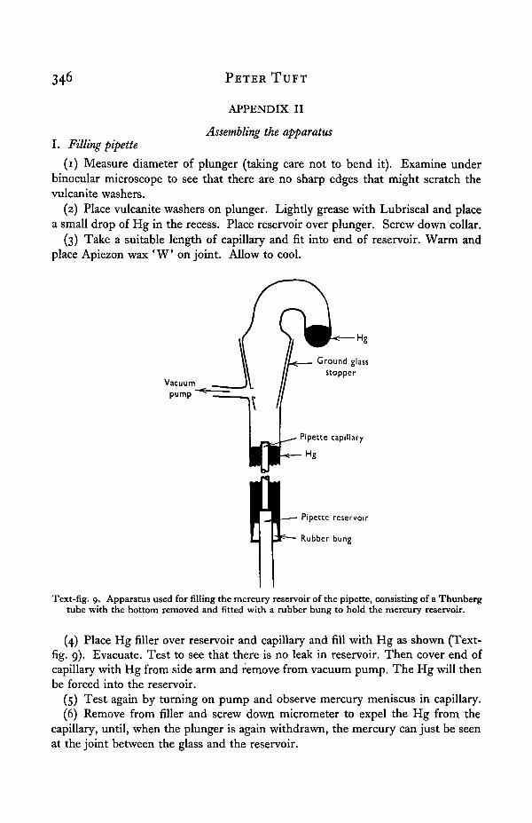
Assembling the apparatusI. Filling pipette
(1) Measure diameter of plunger (taking care not to bend it). Examine underbinocular microscope to see that there are no sharp edges that might scratch thevulcanite washers.
(2) Place vulcanite washers on plunger. Lightly grease with Lubriseal and placea small drop of Hg in the recess. Place reservoir over plunger. Screw down collar.
(3) Take a suitable length of capillary and fit into end of reservoir. Warm andplace Apiezon wax ' W o n joint. Allow to cool.
Vacuumpump
Ground glassstopper
Pipette capillary
Hg
Pipette reservoir
Rubber bung
Text-fig. 9. Apparatus used for filling the mercury reservoir of the pipette, consisting of a Thunbergtube with the bottom removed and fitted with a rubber bung to hold the mercury reservoir.
(4) Place Hg filler over reservoir and capillary and fill with Hg as shown (Text-fig. 9). Evacuate. Test to see that there is no leak in reservoir. Then cover end ofcapillary with Hg from side arm and remove from vacuum pump. The Hg will thenbe forced into the reservoir.
(5) Test again by turning on pump and observe mercury meniscus in capillary.(6) Remove from filler and screw down micrometer to expel the Hg from the
capillary, until, when the plunger is again withdrawn, the mercury can just be seenat the joint between the glass and the reservoir.
Micro-respirometer with automatic setting and recording apparatus
II. Assembling manometer component
(1) Slide the manometer frame into position and clamp the stainless steel blockon to it.
(2) Bend the pipette capillary with a microflame until open end drops into thecentre hole in stainless steel block.
(3) Remove the stainless steel block.(4) Warm the ends of the capillary U-tube and melt on a drop of Apiezon ' W .
Do the same to the open end of the pipette capillary.(5) Replace the block and heat it with the flame until the wax on the pipette
capillary begins to flow over the metal. Then place, the U-tube in position. Heatthe block until wax ' melts' on to the surface.
(6) Allow to cool. Place Perspex guard in position, and fit rubber tubing tonipples on the valves and pipette casing.
(7) With a bent capillary place a drop of odourless kerosene in the U-tube whichshould have been carefully cleaned before assembling.
Inspection before use
(1) Screw micrometer up and down and ensure that the mercury is movingsmoothly.
(2) Examine the valve seatings to see that the edges of the holes are not scratched.(3) Examine pointed ends of the needles. Warm in a flame and grease lightly.(4) Test ground surfaces of vessels. A small drop of water sufficient to cover
the ground surface when it is pressed on to the slide should be enough to make thevessel stick to the slide.
(5) Tilt instrument and observe kerosene to ensure that it moves freely.
Caution
Care should be taken not to allow kerosene to touch the waxed joints. A small rollof filter-paper in the cavities in the block when adding kerosene is a useful safeguard.
APPENDIX III
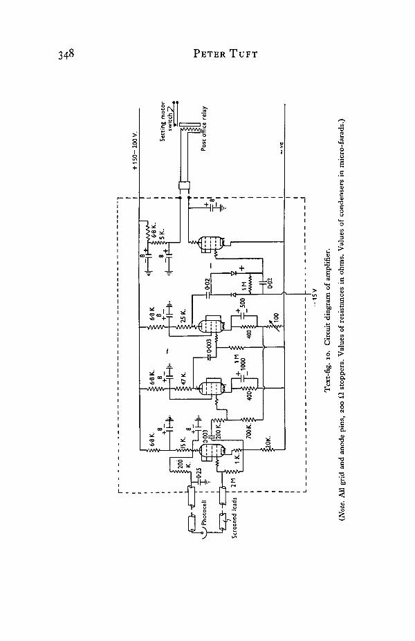
The Amplifier
The circuit shown in Text-fig. 10 forms the link in the servo mechanism whichcontrols the setting motor.
To avoid difficulties of d.c. amplifier operation, the light source is chopped at500 c.p.s. and is focused as described on to the photocell ('Cintel' V.A. 31 made byMessrs Cine Television Ltd.)—a vacuum-type photocell with a sensitivity of about10 /xA/lumen. This is followed by a cathode follower stage with an effective inputimpedance of 25-30 MO. The cathode follower output is fed to a two-stage amplifierwith a maximum gain of 10,000: gain is controlled by a variable negative feedback.The output from the amplifier stage at 500 c.p.s. is rectified in a voltage doublercircuit. The positive going d.c. output from the rectifier is connected directly to the
JOURNAL OF EXPERIMENTAL BIOLOGY, 27, 3 & 4 PLATE 11
Fig, i.
Fig. 2.
TUFT—MICRO-RESPIROMETER WITH AUTOMATIC SETTINGAND RECORDING APPARATUS

Micro-respirometer with automatic setting and recording apparatus 349
grid of the final valve, which is arranged normally to have a standing bias of —15 V.,under these conditions it is cut off and the motor relay therefore opens; the relayoperates at a grid voltage of —3, i.e. for a rectified signal voltage of 12 V. Atmaximum gain the system should thus be operative for a light input in the order oficr4 lumens, in practice about io~3 is available at the photcell.
The circuit has been thoroughly decoupled, particular care being taken to isolatethe relay operating surges from the common h.t. supply. Battery operation is usedthroughout for both the h.t. and l.t.
REFERENCESLINDERSTROM-LANG, K. & HOLTER, H. (1943). C.R. Lab. Carkberg.
Serie Chimique 24, nos. 17 and 18.STEFFANELLI, A. (1937). J. Exp. Biol. 14, 171.TOBIAS, J. M. (1943). Physiol. Rev. 23, no. 1.ZEUTHEN, E. (1943). C.R. Lab. Carkberg, 24, 408.
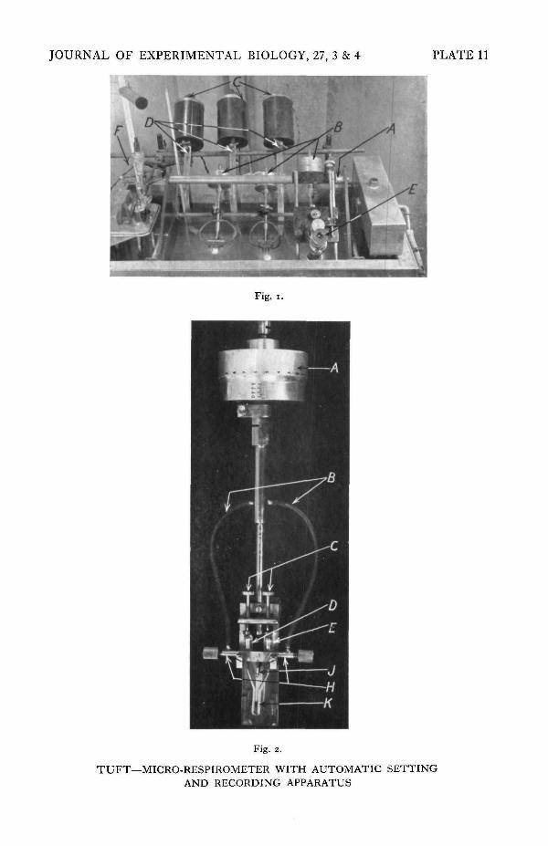
EXPLANATION OF PLATE u
Fig. 1. The experimental layout showing three micro-respirometers in position. A, supporting frame;B, micro-respirometers; C, lamp housings; D, Perspex light ducts; E, microscope; F, thermostatand heater unit.
Fig. 2. A micro-respirometer, x 0-9. A, micrometer head; B, rubber tubes connecting the vesselswith the atmosphere; C, clamping screws; D, compensating vessel; E, reaction vessel;H, needle valves; J, pipette capillary; K, U-tube.
I E B . 2 7 , 3 * 4 23
Recommended