Embed Size (px)
Citation preview

Your Pre-Engineered Solution for Well Pump Motors and VFDs
www.Drivehotline.com Call 888-949-8337
FECA-BR-102a
3 - YearWarranty

• UL Type 3R Listed
• Broad range of power ratings:
230V: 5 – 125Hp
460V: 5 – 600Hp
• White powder coat reflective paint to reduce
solar heat gain within the enclosure
• Thermostat controlled cooling fans
• Input circuit breaker including a pad lockable
through the door operator handle that is
interlocked with the enclosure door
• Service entrance rated and labeled
• Dual rated and labeled for 1 phase or 3 phase
input power
• Door mounted drive keypad with protective
hinged cover
• Modbus RTU communications
• Easy access to washable ventilation filters
• Optional door mounted operator controls
package consisting of a Hand-Off-Auto
selector switch, a speed potentiometer and
the drive keypad all protected by a solid
hinged cover.
• Optional thermostat controlled enclosure
space heater
• Optional high ambient additional cooling
• Optional floor-stand kits for wall-mount style
enclosures
• Additional engineered to order ratings (460V:
700 – 900Hp) or features are available by
contacting your local Fuji Electric sales
representative
The FRENIC-EcoPUMP Type 3R packaged AC drive offering provides a solution designed for outdoor pumping applications. With specific pump application features like; PID control with sleep mode & boost, broken pipe detection, pipe fill mode, submersible pump start control, transducer feedback signal loss detection and more, the FRENIC-EcoPUMP allows for easy installation and commissioning. Additional benefits include; less peripheral equipment required, easy maintenance, energy savings, improved process control and reduced mechanical stress on the pumping system.
www drivehotline.com.
Pre-Engineered Solution for Pump Drives
3 - YearWarranty
Product Features

Height
Height
Depth
Depth
Width
Width
www drivehotline.com. Call 888-949-8337
UL/NEMA Type 3R (Suitable for Outdoor Use)Enclosure
Environmental
Ambient Temperature (Standard) +14 to +104 ºF (-20 to +40 ºC)
+5 to +113 ºF (-15 to +45 ºC)Ambient Temperature (Optional)
Storage Temperature +5 to +140 ºF (-15 to +60 ºC)
Humidity 5% to 95% with no condensation
Altitude 0 to 3,300 ft. (1,000 m) without derating, derate output current by 1% for each additional 330 ft. (100 m)
Speci�cations
Dimensions
FEA-ACDR-DS-103A
Est. WeightHeight Width Depth
(lbs)
5 A 35.00 24.15 18.08 2147.5 A 41.00 24.15 18.08 36610 A 41.00 24.15 18.08 44615 A 47.00 24.15 20.08 61020 A 47.00 27.39 20.08 87225 A 55.00 36.19 22.01 92030 A 55.00 36.19 22.01 116940 A 67.00 36.19 22.01 154950 A 67.00 36.19 22.01 146660 A 67.00 36.19 22.01 179375 B 91.06 40.39 39.54 2100100 B 91.06 40.39 39.54 2701125 B 91.06 60.06 45.54 3898
5 A 35.00 24.15 18.08 1877.5 A 35.00 24.15 18.08 19110 A 41.00 24.15 18.08 36415 A 41.00 24.15 18.08 39820 A 41.00 24.15 18.08 52125 A 47.00 24.15 20.08 60930 A 47.00 24.15 20.08 65240 A 47.00 27.39 20.08 107750 A 55.00 36.19 22.01 130360 A 55.00 36.19 22.01 147275 A 67.00 36.19 22.01 1538100 A 67.00 36.19 22.01 1757125 B 91.06 40.39 39.54 2195150 B 91.06 40.39 39.54 2521200 B 91.06 52.39 41.54 3132250 B 91.06 52.39 41.54 3952300 B 91.06 52.39 41.54 4624350 B 91.06 52.39 41.54 5417400 B 91.06 60.06 45.54 6025450 B 91.06 60.06 45.54 6581500 B 91.06 60.06 45.54 7986600 B 91.06 60.06 45.54 9096
230V
460V
Hp Figure
Note: Dimensions listed above are based on standard ambient temperature design.
Figure B
Figure A

• Pre-engineered solution for pump drives EcoPUMP was designed for pump applications, including advance PID control with sleep mode, broken pipe detection, pipe fill mode, submersible pump, and much more to accommodate a wide range of applications. Integrated pump specific firmware allows the user an easy set up, and EcoPUMP will automatically adjust itself to optimal operation condition.
• Energy Saving Energy savings can be achieved by utilizing variable speed drives to adjust motor speed for meeting demand flow instead of mechanical devices, such as dampers or valves. Eco-PUMP allows the user to easily match pump speed to lower flow rate or pressure for optimal energy saving in pump applications.
• Many additional features and options available Equipped with analog inputs directly monitoring the actual value, and application specific alarms for user friendliness. EcoPUMP provides many additional features and benefits for all types of pump applications
• Longer life and lower system cost By eliminating complex controller and mechanical components, EcoPUMP reduces mechanical stress and lowers system cost as well as provides longer system life. Backed by Fuji’s standard 3 year warranty in the USA, EcoPUMP is a true winner for all pump applications.
SIMPLIFIED SET UP FOR PRE-ENGINEERED PUMP DRIVES• Eliminating HMI, PLC, or external control systems• Less components for simple installation • Less peripheral equipment • Easy Maintenance• Quicker Start up procedure• Smooth Operation
10 years design life & less hardware requirements
DUAL DISPLAY KEYPAD • LED for monitoring and intelligent
back light LCD for programming & trouble shooting
• Works as Copy unit for easy transfer• Available to display in actual PID unit (PIS, GPM, and etc) • Stores up to 3 inverters programs • Remote/local switching key allows quick changeover. • Quick setup function codes can be customized to desired function codes. • Load ratio can be measured (24 hours). • Communications debugging function • Standard RJ45 patch cable for easy extension
3 year Standard Warranty
Energy saving effect compared with Fuji’s previous models
(The effect varies dependent on the motor’s characteristics.)
Energy savingseffect
Inverter control(V/f control)
Previous auto energysaving control
New auto energysaving control(Optimal minimumpower control)
Characteristic curve achievedby controlling a damper or valve
PumpPump
Feedback
FEATURES
LCD Moni-tor
Program key
Shift key
Reset key
Up key
Down key
Remote/ local key
Function/Data key
Stop key
RUN key (reverse)
LED indicator
RUN key (forward)
LED indicator indexes
7-segment LED Monitor
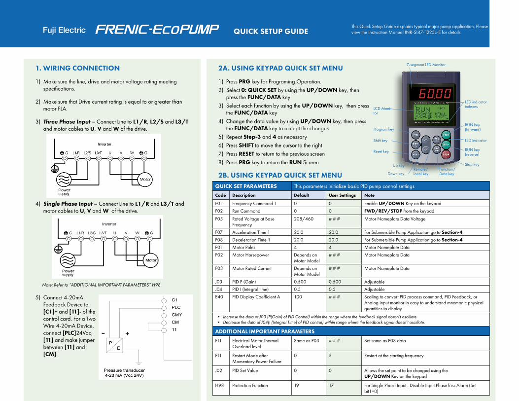
This Quick Setup Guide explains typical major pump application. Please view the Instruction Manual INR-SI47-1225c-E for details.
1. WIRING CONNECTION
1) Make sure the line, drive and motor voltage rating meeting specifications.
2) Make sure that Drive current rating is equal to or greater than motor FLA.
3) Three Phase Input – Connect Line to L1/R, L2/S and L3/T and motor cables to U, V and W of the drive.
4) Single Phase Input – Connect Line to L1/R and L3/T and motor cables to U, V and W of the drive.
Note: Refer to “ADDITIONAL IMPORTANT PARAMETERS” H98
5) Connect 4-20mA Feedback Device to [C1]+ and [11]- of the control card. For a Two Wire 4-20mA Device, connect [PLC]24Vdc, [11] and make jumper between [11] and [CM].
2A. USING KEYPAD QUICK SET MENU
1) Press PRG key for Programing Operation.2) Select 0: QUICK SET by using the UP/DOWN key, then
press the FUNC/DATA key3) Select each function by using the UP/DOWN key, then press
the FUNC/DATA key4) Change the data value by using UP/DOWN key, then press
the FUNC/DATA key to accept the changes5) Repeat Step-3 and 4 as necessary6) Press SHIFT to move the cursor to the right7) Press RESET to return to the previous screen8) Press PRG key to return the RUN Screen
2B. USING KEYPAD QUICK SET MENUQUICK SET PARAMETERS This parameters initialize basic PID pump control settings
Code Description Default User Settings Note
F01 Frequency Command 1 0 0 Enable UP/DOWN Key on the keypad
F02 Run Command 0 0 FWD/REV/STOP from the keypad
F05 Rated Voltage at Base Frequency
208/460 # # # Motor Nameplate Data Voltage
F07 Acceleration Time 1 20.0 20.0 For Submersible Pump Application go to Section-4
F08 Deceleration Time 1 20.0 20.0 For Submersible Pump Application go to Section-4
P01 Motor Poles 4 4 Motor Nameplate Data
P02 Motor Horsepower Depends onMotor Model
# # # Motor Nameplate Data
P03 Motor Rated Current Depends onMotor Model
# # # Motor Nameplate Data
J03 PID P (Gain) 0.500 0.500 Adjustable
J04 PID I (Integral time) 0.5 0.5 Adjustable
E40 PID Display Coefficient A 100 # # # Scaling to convert PID process command, PID Feedback, or Analog input monitor in easy to understand mnemonic physical quantities to display
・• Increase the data of J03 (P(Gain) of PID Control) within the range where the feedback signal doesn’t oscillate.・• Decrease the data of J04(I (Integral Time) of PID control) within range where the feedback signal doesn’t oscillate.
ADDITIONAL IMPORTANT PARAMETERS
F11 Electrical Motor Thermal Overload level
Same as P03 # # # Set same as P03 data
F11 Restart Mode after Momentary Power Failure
0 5 Restart at the starting frequency
J02 PID Set Value 0 0 Allows the set point to be changed using theUP/DOWN Key on the keypad
H98 Protection Function 19 17 For Single Phase Input . Disable Input Phase loss Alarm (Set bit1=0)
LCD Moni-tor
Program key
Shift key
Reset key
Up key
Down keyRemote/ local key
Function/ Data key
Stop key
RUN key (reverse)
LED indicator
RUN key (forward)
LED indicator indexes
7-segment LED Monitor
QUICK SETUP GUIDE

2C. USING KEYPAD QUICK SET MENU 2D. USING KEYPAD QUICK SET MENU
SLEEP/WAKE MODE Selectable to activate or deactivate on speed or pressure
Code Description Default User Settings
Note
J56 Sleep Mode - Signal Reference
0 1 Enable for Sleep Mode Starting (Stop) reference value. (1=PID output value (MV) is referenced for Starting (Stop) level)
J57 Sleep Mode - Start Level Reference
0.00 hz # # # Sleep mode starting PID output level MV (set in Hz, which specifies MV% where MV=100%=F03). For example, when you set 54Hz in J57, Sleep mode is started when MV becomes 90%, that means Feedback value ismore than the Set point value.
J58 Sleep Mode - Delay Timer
0 sec # Sleep Mode start delay timer
J63 Wake Mode - Input Reference
0 4 Enables Wake Mode from Sleep Mode conditions, using PID feedback 1 reference input
J64 Wake Mode - Start Level Reference
0 psi # # # Wake Mode starting level in this case PID Feedback 1 is PSI value
J65 Wake Mode - Delay Timer
0 sec # Wake Mode start delay timer
ALARM FOR HIGH FREQUENCY
Wake frequency protection to prevent unnecessary cycling ON/OFF. Set using the number of cycles and time
Code Description Default User Settings
Note
J68 Cycling Protection for Slow Flow rate
0 # Limit the number of cycles up to 10
J69 Maximum Cycling Protec-tion Time
300 sec # # # Max allowable time between cycles adjustable
Number of times(J68) : 3
3. TEST RUN THE MOTOR
Basic PID Pump Control Setup for Section 1&2.
1) Press PRG until you get to the Running screen – Keypad LCD should display SV and PV – Keypad LED should blink 00.00
2) Pressure Setting: (in PSI unit scaled 0 to 100% range)
3) Feedback: PV (4-20mA input device; in PSI unit scaled 0 to 100% range)
4) Press UP/DOWN key to adjust SV
5) Press FWD key to start the motor
6) If motor rotates the opposite direction; – Press STP key and turn off the power to the drive – Swap any of the two motor cables
7) If motor doesn’t rotate by Step-4, check the feedback PV value and set SV higher than PV
8) Check that there is no abnormal sound and vibration coming from the motor
9) Adjust J03 and J04 from the “Quick Set Parameters” and other parameters as needed
4A. COMMON PUMP APPLICATION SETUP
1) Choose settings based on your motor and pump specifications
2) Press PRG key for PROGRAMMING OPERATION
3) Select 1: DATA SET by using the UP/DOWN key, then press the FUNC/DATA key
4) Refer to Section-2 of FRENIC-EcoPUMP Instruction manual (INR-SI47-1484E) for detail

4B. COMMON PUMP APPLICATION SETUP
4C. COMMON PUMP APPLICATION SETUP
4D. SUBMERSIBLE PUMP SETUP
DETECT FEEDBACK ALARM High and Low Pressure detection, the timer and levels can be set to alarm or fault based on the feedback
Code Description Default User Settings
Note
J11 PID Control Select Alarm Output 0 # # # Must be greater than 0 to enable
J12 Upper limit alarm (AH) 999 # # # Specifies the feedback upper level limit
J13 Upper alarm delay time 2 sec 2 Delay the timer to trigger the feedback alarm (AH)
J14 Lower limit alarm (AL) -999 # # # Specifies the feedback lower level limit
J15 Lower alarm delay time 120 sec 120 Delay the timer to trigger the feedback alarm (AL)
PIPE FILL MODE The Fixed Hz/Speed is chosen by the user that runs until a timer expires or a separate pipe fill pressure is satisfied
Code Description Default User Settings
Note
J07 Start Pipe Fill Frequency 0.0 # #Fixed speed(Hz) of Pipe Fill Mode (Pipe Fill Mode is enabled with any value other than 0.0)
J08 Start Pipe Fill Level 0.01 # # #Pipe Fill Mode Operation stops Feedback value level for PID control start
J09 Start Pipe Fill Time 0.01 # # # Duration of Fixed (Hz) speed for Pipe Fill Mode
J10 Start Pipe Fill Acceleration Time 0.01 # # # Acceleration time to J07 (Pipe Fill Mode)
SUBMERSIBLE PUMP START Sets a speed (usually 30Hz) and a timer (usually 1 sec) separate from the normal ACC/DEC times. Per the manufactures, submersible pump motors must reach 30Hz in 1 second. This is to ensure bearings and motor cooling requirements.
Code Description Default User Settings
Note
E12 Acceleration time 3 0.00 1.00 1second acceleration to 30HZ (E14)
E13 Deceleration time 3 1.00 1.00
E14 Acc/Dec time change Hz 30.0 30.0 Acceleration ramp change HZ (E12/E13 - F07/F08)
E14
OutputFrequency
t
tFWD ON
E12 F07
SettingFrequency
To learn more about BMR- USA amd Fuji’s AC Drive Solutions, please call www.drivehotline.com 888-949-8337

www.drivehotline.com Tel: 888-949-8337
BMR-USA
ENVIRONMENTAL
Enclosure Open Type (IP20/IP00), Type 1
Ambient Temperature +14 to +122° F (-10 to +50° C) [+104° F(+40° C) for NEMA 1]
Storage Temperature +5 to +140° F (-15 to +60° C)
Humidity 5% to 95% with no condensation
Altitude 0 to 3,300 ft. (1,000 m) without derating, derate output current above 3,300 ft. (1,000 m) per instruction manual
CODES AND STANDARDS
UL Listed per UL508C, C22.2 No. 14, EN50178:1997
Conforms to applicable NEMA ICS, NFPA, & IEC standards
ELECTRICAL
Input Voltage: Nominal - Phase 208VAC, 230VAC, 460VAC - Single or 3 Phase
Input Voltage: Tolerance, Unbalance -15% to +10%, <2%
Input Frequency 50,60Hz +/-5%
Output Voltage: Range - Phase 0 to maximum input voltage - 3 Phase
Output Frequency 0.1 to 120Hz
Horsepower Range 1 to 125Hp @ 208V, 3 Phase Input1/2 to 40Hp @ 208V, Single Phase Input1 to 900Hp @ 460V, 3 Phase Input1/2 to 250Hp @ 460V, Single Phase Input
PWM Switch Frequency 0.75 to 15kHz (1 to 25Hp for 208/230V and 1 to 30Hp for 460V)0.75 to 10kHz (30 to 100Hp for 208/230V and 40 to 100Hp for 460V)0.75 to 6kHz (125Hp for 208V and 125 to 900Hp for 460V)
Drive Overload Capacity 120% rated current for 1 min.
Motor Overload Programmable (electronic)
CONTROL
Motor Control Method PWM drive output with V/f control, includes programmable "catch-a-spinning motor" function
Motor Automatic Tuning Automatically adjusts motor parameters for optimum performance
Speed Reference Inputs 0 to +10VDC, 4 to 20mA, Keypad, Digital Inputs, Preset Speeds, Communication Link
Speed Reference Resolution Analog setting: 1/1000 of maximum frequencyKeypad setting: 0.01Hz (99.99Hz or less)
Acceleration/Deceleration Time 0 to 3600 seconds with four user selectable patterns (S-curve [weak], S-curve [strong], Curve, & Linear), and coast to stop
Digital Input Signals Qty 7 programmable inputs
Torque Boost Programmable to provide additional starting torque if required
Jump Frequencies Qty 3 programmable frequency set points with adjustable jump bandwidth of 0 to 30Hz
Restart After Momentary Power Failure 5 programmable settings to meet application requirements
Automatic Energy Savings Minimizes motor and drive losses at constant speed
Overload Prevention Control Reduction of drive output to avoid tripping the drive due to increase ambient temperature or motor load
Automatic Deceleration Automatically extends the deceleration time to avoid overvoltage trips
Fully Featured PID for Pumping Applications
6 different selections for process command (set-point)0-10Vdc or 4-20mA sensor feedbackPump functions include: sleep mode, normal/inverse operation, pipe fill mode, broken pipe detection, alarm output, etc…
Communication Interface RS485 Modbus RTU as standard
INDICATION
Keypad LED Panel Functions as a meter for displaying; output frequency, output amps, output voltage, torque, motor RPM, input power, PID set-point value, or PID feedback value
Keypad LCD Panel Functions as interface for programming and troubleshooting
Digital & Analog Output Signals Transistor outputs - qty 3 (programmable)Relay outputs - qty 1 form C and qty 1 form A (programmable)Voltage output - 0-10Vdc (programmable)Current output - 4-20mA (programmable)
Protective Trip Codes 29 unique trip codes for displaying the cause of a trip
Trip History Last 4 trip codes and information is saved for review
GENERAL SPECIFICATIONS