Embed Size (px)
Citation preview

XPI - CFS Engineering
Magnetic Actuator FEA Co-Simulation: Ansys Maxwell and GT Suite
Ben Manring, PhD Ahmad Sabri, PhD Cummins Fuel Systems
Iakovos Papadimitriou Shawn Harnish Gamma Technologies
Mark Solveson, PhD Xiao Hu, PhD ANSYS

Magnetic Actuators in GT Suite Actuators can be modelled in a number of ways in GT Suite:
Imposed displacement
• Often works well in large system simulations where minute detail is unnecessary.
Various table techniques • Transfer function from given variable to displacement.
Imposed force • Inertia, damping and friction, and other forces account for resulting
motion. Imposed current in a lumped parameter 1D magnetic model
• Magnetic force is calculated and equations of motions solved. Current calculated from voltage driven electronic circuit,
including BEMF effects from the actuator magnetodynamics. • Magnetic force is calculated and equations of motion solved.

The above methods suffer from an inability to take into account the following effects, which are especially important to consider in fast acting actuators, or actuators made of solid materials (contrasted with laminated or insulated powder materials): • Distributed field effects
2D and 3D effects can only be approximated in lumped parameter models.
• Corresponding material behavior as a function of distributed
field magnitudes. Nonlinear materials can be modelled in GT lumped parameter
components, but the effects are averaged. • Eddy current effects
A so-called “eddy inductance” can be included in a lumped parameter model to approximate this effect.

Solution Incorporate a finite element (FEA) model in the system simulation via co-simulation Co-simulation is necessary because dynamic magnetic behavior, including eddy current activity, has an effect on motion and the electronic circuit, which in turn both affect the magnetic behavior.

The co-simulation described here was a joint effort between Gamma Technologies, ANSYS, and Cummins.
• GT provides calculations for the hydraulic forces, mechanical stops, electric current, and voltage, while Maxwell returns magnetic force and back EMF to GT. GT sums the forces and solves the equations of motion. The two programs communicate by reading and writing to a common file.

This element is the
Maxwell model

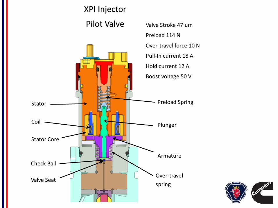
Maxwell results during the simulation, showing realistically modelled electronic signals, magnetic force, and armature Displacement.
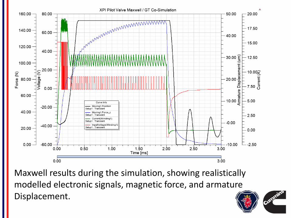
Displacement comparison between measurements and simulation.

Eddy and BEMF dominated valve
(in air)
Stator
Coil
Armature
Axi-symmetric Axis

This element is the
Maxwell model
Simpler valve in air

Actuator performance agreement between simulation and measurement is quite good.

GT Suite / ANSYS Maxwell Co-simulation Summary
1. Necessary to model highly detailed behavior of electromagnetic actuator behavior, especially for BEMF and eddy current dominated actuators.
2. Not shown above, but excellent agreement with Maxwell alone circuit driven transient analysis.
3. Can experience numerical instabilities due to time-step delays between programs—this is minimized by use of small capacitors in the GT circuit model.
4. Runs reasonably fast—analyses shown take under an hour to run. Longer for 3D. Series resistance with circuit capacitors greatly reduced run times compared to early attempts.
Thanks go to Shawn, Iakovos and the ANSYS team. Great support, much appreciated!