Embed Size (px)
Citation preview

Dell® Latitude® XPi CD
SERVICE MANUAL
®

Information in this manual is subject to change without notice.
1994–1996 Dell Computer Corporation. All rights reserved.
Reproduction in any manner whatsoever without the written permission of Dell Computer Corporation is strictly forbidden.
Trademarks used in this text: Dell, the DELL logo, and Latitude are registered trademarks of Dell Computer Corporation; Microsoft, Windows, and MS-DOS are registered trademarks of Microsoft Corporation; Intel and Pentium are registered trademarks of Intel Corporation; IBM is a registered trademark of International Business Machines Corporation.
Other trademarks and trade names may be used in this document to refer to either the entities claiming the marks and names or their products. Dell Computer Corporation disclaims any proprietary interest in trademarks and trade names other than its own.
October 1996 P/N 30269

Contents
. . 1-1
. 1-2
. 1-3
. 1-4
1-4
-4
. 1-4
1-4
. 1-4
. 1-5
. 1-5
. . 1-5
. 1-6
. 1-7
. 2-1
. 2-1
. 2-4
. 2-5
. 2-5
Chapter 1System Overview. . . . . . . . . . . . . . . . . . . . . . . . . . . . . . . 1-1
System Features . . . . . . . . . . . . . . . . . . . . . . . . . . . . . . . . . . . . . . . . . . . . .
Physical Description . . . . . . . . . . . . . . . . . . . . . . . . . . . . . . . . . . . . . . . . . . .
Indicator Panel . . . . . . . . . . . . . . . . . . . . . . . . . . . . . . . . . . . . . . . . . . . .
Power/Suspend Indicator . . . . . . . . . . . . . . . . . . . . . . . . . . . . . . . . .
Diskette-Drive Access Indicator . . . . . . . . . . . . . . . . . . . . . . . . . . . . .
Hard-Disk/CD-ROM Drive Access Indicator. . . . . . . . . . . . . . . . . . . 1
PC Card Access Indicator . . . . . . . . . . . . . . . . . . . . . . . . . . . . . . . . .
Low-Battery Indicator. . . . . . . . . . . . . . . . . . . . . . . . . . . . . . . . . . . . .
Charging Indicator . . . . . . . . . . . . . . . . . . . . . . . . . . . . . . . . . . . . . .
Keyboard Indicators . . . . . . . . . . . . . . . . . . . . . . . . . . . . . . . . . . . . .
Controlling Computer Power . . . . . . . . . . . . . . . . . . . . . . . . . . . . . . . . . . . .
Power States . . . . . . . . . . . . . . . . . . . . . . . . . . . . . . . . . . . . . . . . . . . . .
Interrupt Assignments. . . . . . . . . . . . . . . . . . . . . . . . . . . . . . . . . . . . . . . . . .
Technical Specifications . . . . . . . . . . . . . . . . . . . . . . . . . . . . . . . . . . . . . . . .
Chapter 2Initial Procedures . . . . . . . . . . . . . . . . . . . . . . . . . . . . . . 2-1
Initial User Contact . . . . . . . . . . . . . . . . . . . . . . . . . . . . . . . . . . . . . . . . . . . .
Visual Inspection . . . . . . . . . . . . . . . . . . . . . . . . . . . . . . . . . . . . . . . . . . . . .
Observing the Boot Routine . . . . . . . . . . . . . . . . . . . . . . . . . . . . . . . . . . . . .
Eliminating Resource Conflicts . . . . . . . . . . . . . . . . . . . . . . . . . . . . . . . . . .
Getting Help . . . . . . . . . . . . . . . . . . . . . . . . . . . . . . . . . . . . . . . . . . . . . . . . .
v

vi
. . 3-1
. . 3-3
. 3-8
. . 4-2
. . 4-2
. 4-4
. 4-5
. . 4-6
4-7
. 4-8
. 4-9
4-10
4-13
4-14
4-16
4-16
4-18
4-20
4-21
4-22
4-24
4-25
4-26
4-28
4-29
-31
4-33
4-34
4-36
4-38
4-39
4-40
4-41
Chapter 3Beep Codes and Error Messages . . . . . . . . . . . . . . . . . . 3-1
POST Beep Codes . . . . . . . . . . . . . . . . . . . . . . . . . . . . . . . . . . . . . . . . . . .
System Error Messages . . . . . . . . . . . . . . . . . . . . . . . . . . . . . . . . . . . . . . .
Running the Dell Diagnostics. . . . . . . . . . . . . . . . . . . . . . . . . . . . . . . . . . . .
Chapter 4Removing and Replacing Parts . . . . . . . . . . . . . . . . . . . 4-1
Recommended Tools . . . . . . . . . . . . . . . . . . . . . . . . . . . . . . . . . . . . . . . . .
Precautionary Measures . . . . . . . . . . . . . . . . . . . . . . . . . . . . . . . . . . . . . . .
Screw Identification and Tightening . . . . . . . . . . . . . . . . . . . . . . . . . . . . . .
ZIF Connectors. . . . . . . . . . . . . . . . . . . . . . . . . . . . . . . . . . . . . . . . . . . . . . .
Field-Replaceable Parts and Assemblies . . . . . . . . . . . . . . . . . . . . . . . . . .
Hard-Disk Drive Assembly . . . . . . . . . . . . . . . . . . . . . . . . . . . . . . . . . . .
Memory Compartment Cover . . . . . . . . . . . . . . . . . . . . . . . . . . . . . . . .
Memory Modules . . . . . . . . . . . . . . . . . . . . . . . . . . . . . . . . . . . . . . . . . .
Palmrest Assembly . . . . . . . . . . . . . . . . . . . . . . . . . . . . . . . . . . . . . . . . . . . .
Trackball Assembly . . . . . . . . . . . . . . . . . . . . . . . . . . . . . . . . . . . . . . . .
Keyboard Assembly . . . . . . . . . . . . . . . . . . . . . . . . . . . . . . . . . . . . . . . .
Display Assembly. . . . . . . . . . . . . . . . . . . . . . . . . . . . . . . . . . . . . . . . . . . . .
Tilt-Support Foot . . . . . . . . . . . . . . . . . . . . . . . . . . . . . . . . . . . . . . . . . .
Display Assembly. . . . . . . . . . . . . . . . . . . . . . . . . . . . . . . . . . . . . . . . . .
Display Assembly Bezel . . . . . . . . . . . . . . . . . . . . . . . . . . . . . . . . . . . .
Display Assembly Latch and Latch Spring . . . . . . . . . . . . . . . . . . . . . .
LCD Panel . . . . . . . . . . . . . . . . . . . . . . . . . . . . . . . . . . . . . . . . . . . . . . .
LCD Inverter Board . . . . . . . . . . . . . . . . . . . . . . . . . . . . . . . . . . . . . . . .
Hinge Covers . . . . . . . . . . . . . . . . . . . . . . . . . . . . . . . . . . . . . . . . . . . . .
Display-Assembly Interface Cable. . . . . . . . . . . . . . . . . . . . . . . . . . . . .
Microphone/Switch Assembly . . . . . . . . . . . . . . . . . . . . . . . . . . . . . . . .
Bottom Case Assembly . . . . . . . . . . . . . . . . . . . . . . . . . . . . . . . . . . . . . . . .
Diskette/CD-ROM Drive Assembly . . . . . . . . . . . . . . . . . . . . . . . . . . . 4
Deck Buoy . . . . . . . . . . . . . . . . . . . . . . . . . . . . . . . . . . . . . . . . . . . . . . .
Superpart Assembly . . . . . . . . . . . . . . . . . . . . . . . . . . . . . . . . . . . . . . . .
Reserve Battery . . . . . . . . . . . . . . . . . . . . . . . . . . . . . . . . . . . . . . . . . . .
System Board Assembly . . . . . . . . . . . . . . . . . . . . . . . . . . . . . . . . . . . .
Removing the System Board Assembly . . . . . . . . . . . . . . . . . . . . . .
Replacing the System Board Assembly . . . . . . . . . . . . . . . . . . . . . .
3.1-V Power Supply Board . . . . . . . . . . . . . . . . . . . . . . . . . . . . . . . . . .

4-42
4-43
4-44
. .A-1
. .A-1
. .A-1
A-12
-15
-16
-16
.A-16
A-16
-16
-16
A-16
A-17
-17
A-18
-19
.A-20
A-20
-21
A-22
A-23
A-24
.A-25
-25
-26
.A-27
.B-1
. .B-2
. .B-3
I/O-Panel Dust Cover . . . . . . . . . . . . . . . . . . . . . . . . . . . . . . . . . . . . . . .
Advanced Port Replicator Connector Dust Cover . . . . . . . . . . . . . . . . .
Audio Board . . . . . . . . . . . . . . . . . . . . . . . . . . . . . . . . . . . . . . . . . . . . . .
Appendix AFactory Repair Parts . . . . . . . . . . . . . . . . . . . . . . . . . . . . A-1
Recommended Tools . . . . . . . . . . . . . . . . . . . . . . . . . . . . . . . . . . . . . . . . .
Precautionary Measures . . . . . . . . . . . . . . . . . . . . . . . . . . . . . . . . . . . . . . .
Factory Repair Parts and Assemblies . . . . . . . . . . . . . . . . . . . . . . . . . . . . .
Exploded Views of Components and Assemblies . . . . . . . . . . . . . . . . . . . .
Hard-Disk Drive . . . . . . . . . . . . . . . . . . . . . . . . . . . . . . . . . . . . . . . . . . .A
CD-ROM Drive . . . . . . . . . . . . . . . . . . . . . . . . . . . . . . . . . . . . . . . . . . .A
Diskette Drive . . . . . . . . . . . . . . . . . . . . . . . . . . . . . . . . . . . . . . . . . . . . .A
Palmrest Assembly Components . . . . . . . . . . . . . . . . . . . . . . . . . . . . . . . .
Trackball . . . . . . . . . . . . . . . . . . . . . . . . . . . . . . . . . . . . . . . . . . . . . . . . .
Trackball Interface Cable . . . . . . . . . . . . . . . . . . . . . . . . . . . . . . . . . . . .A
Trackball Button Board . . . . . . . . . . . . . . . . . . . . . . . . . . . . . . . . . . . . .A
Palmrest Brace . . . . . . . . . . . . . . . . . . . . . . . . . . . . . . . . . . . . . . . . . . . .
Display Assembly Components . . . . . . . . . . . . . . . . . . . . . . . . . . . . . . . . . .
Display-Assembly EMI Shield . . . . . . . . . . . . . . . . . . . . . . . . . . . . . . . .A
Display Assembly Base . . . . . . . . . . . . . . . . . . . . . . . . . . . . . . . . . . . . .
Display Assembly Hinges. . . . . . . . . . . . . . . . . . . . . . . . . . . . . . . . . . . .A
System-Board Assembly Components . . . . . . . . . . . . . . . . . . . . . . . . . . . .
System Board . . . . . . . . . . . . . . . . . . . . . . . . . . . . . . . . . . . . . . . . . . . . .
Keyboard/Keypad/Mouse Connector Shield . . . . . . . . . . . . . . . . . . . . .A
I/O Interface Cable . . . . . . . . . . . . . . . . . . . . . . . . . . . . . . . . . . . . . . . . .
I/O Board . . . . . . . . . . . . . . . . . . . . . . . . . . . . . . . . . . . . . . . . . . . . . . . .
I/O Panel . . . . . . . . . . . . . . . . . . . . . . . . . . . . . . . . . . . . . . . . . . . . . . . . .
Bottom-Case Assembly Components . . . . . . . . . . . . . . . . . . . . . . . . . . . . .
Main Battery Insulator . . . . . . . . . . . . . . . . . . . . . . . . . . . . . . . . . . . . . .A
Power Button and Power-Button Mounting Bracket . . . . . . . . . . . . . . .A
Spreader and Keel Plates . . . . . . . . . . . . . . . . . . . . . . . . . . . . . . . . . . .
Appendix BSystem Setup Options . . . . . . . . . . . . . . . . . . . . . . . . . . B-1
Accessing the Dell Control Center . . . . . . . . . . . . . . . . . . . . . . . . . . . . . . . .
Accessing the System Setup Program . . . . . . . . . . . . . . . . . . . . . . . . . . . .
System Setup Screens . . . . . . . . . . . . . . . . . . . . . . . . . . . . . . . . . . . .
vii

viii
1-2
1-3
. 1-3
. 4-1
4-3
4-4
. 4-5
4-6
4-7
4-8
4-9
4-10
4-11
4-13
4-14
4-16
4-18
4-20
-21
4-22
-24
4-25
4-26
-28
4-30
-31
4-33
4-34
4-36
4-38
4-40
4-41
4-42
4-43
4-44
Index
Figures
Figure 1-1. Front View of the Notebook Computer. . . . . . . . . . . . . . . . . .
Figure 1-2. Back View of the Notebook Computer . . . . . . . . . . . . . . . . . .
Figure 1-3. Indicator Panel. . . . . . . . . . . . . . . . . . . . . . . . . . . . . . . . . . . .
Figure 4-1. Computer Orientation . . . . . . . . . . . . . . . . . . . . . . . . . . . . . .
Figure 4-2. Main Battery Assembly Removal . . . . . . . . . . . . . . . . . . . . . .
Figure 4-3. Screw Identification. . . . . . . . . . . . . . . . . . . . . . . . . . . . . . . . .
Figure 4-4. Disconnecting an Interface Cable . . . . . . . . . . . . . . . . . . . . .
Figure 4-5. Exploded View—Computer . . . . . . . . . . . . . . . . . . . . . . . . . .
Figure 4-6. Hard-Disk Drive Assembly Removal . . . . . . . . . . . . . . . . . . .
Figure 4-7. Memory Compartment Cover Removal . . . . . . . . . . . . . . . . .
Figure 4-8. Memory Module Removal . . . . . . . . . . . . . . . . . . . . . . . . . . .
Figure 4-9. Palmrest Assembly Removal. . . . . . . . . . . . . . . . . . . . . . . . .
Figure 4-10. Palmrest-Assembly Retaining Screws. . . . . . . . . . . . . . . . . .
Figure 4-11. Trackball Assembly Removal . . . . . . . . . . . . . . . . . . . . . . . .
Figure 4-12. Keyboard Assembly Removal . . . . . . . . . . . . . . . . . . . . . . . .
Figure 4-13. Tilt-Support Foot Removal . . . . . . . . . . . . . . . . . . . . . . . . . .
Figure 4-14. Display Assembly Removal . . . . . . . . . . . . . . . . . . . . . . . . .
Figure 4-15. Display Assembly Bezel Removal . . . . . . . . . . . . . . . . . . . .
Figure 4-16. Display Assembly Latch and Latch Spring Removal . . . . . . 4
Figure 4-17. LCD Panel Removal . . . . . . . . . . . . . . . . . . . . . . . . . . . . . . .
Figure 4-18. LCD Inverter Board Removal . . . . . . . . . . . . . . . . . . . . . . . . 4
Figure 4-19. Hinge Covers Removal . . . . . . . . . . . . . . . . . . . . . . . . . . . . .
Figure 4-20. Display-Assembly Interface Cable Removal . . . . . . . . . . . .
Figure 4-21. Microphone/Switch Assembly Removal . . . . . . . . . . . . . . . . 4
Figure 4-22. Bottom Case Assembly Removal . . . . . . . . . . . . . . . . . . . . .
Figure 4-23. Diskette/CD-ROM Drive Assembly Removal . . . . . . . . . . . 4
Figure 4-24. Deck Buoy Removal . . . . . . . . . . . . . . . . . . . . . . . . . . . . . . .
Figure 4-25. Superpart Assembly Removal . . . . . . . . . . . . . . . . . . . . . . . .
Figure 4-26. Reserve Battery Removal . . . . . . . . . . . . . . . . . . . . . . . . . . .
Figure 4-27. System Board Assembly Removal . . . . . . . . . . . . . . . . . . . .
Figure 4-28. I/O Bracket Clips. . . . . . . . . . . . . . . . . . . . . . . . . . . . . . . . . .
Figure 4-29. 3.1-V Power Supply Board Removal . . . . . . . . . . . . . . . . . .
Figure 4-30. I/O-Panel Dust Cover Removal. . . . . . . . . . . . . . . . . . . . . . .
Figure 4-31. Advanced Port Replicator Connector Dust Cover. . . . . . . . .
Figure 4-32. Audio Board Removal . . . . . . . . . . . . . . . . . . . . . . . . . . . . . .

12
-13
-14
17
-20
-21
-22
-23
-24
-25
-26
A-27
B-1
B-1
. .B-3
. 1-6
. 1-7
. . 3-1
. . 3-3
.A-2
. .B-4
Figure A-1. Exploded View—Display Assembly . . . . . . . . . . . . . . . . . . .A-
Figure A-2. Exploded View—Palmrest Assembly . . . . . . . . . . . . . . . . . .A
Figure A-3. Exploded View—Bottom Case Assembly . . . . . . . . . . . . . . .A
Figure A-4. Display-Assembly EMI Shield Removal. . . . . . . . . . . . . . . .A-
Figure A-5. System Board Assembly in the Bottom Case Assembly . . . .A
Figure A-6. Keyboard/Keypad/Mouse Connector Shield Removal . . . . .A
Figure A-7. I/O Interface Cable Removal . . . . . . . . . . . . . . . . . . . . . . . . .A
Figure A-8. I/O Board Removal . . . . . . . . . . . . . . . . . . . . . . . . . . . . . . . .A
Figure A-9. I/O Panel Removal . . . . . . . . . . . . . . . . . . . . . . . . . . . . . . . . .A
Figure A-10. Bottom-Case Assembly Components . . . . . . . . . . . . . . . . . .A
Figure A-11. Power Button and Power-Button Mounting Bracket Removal . . . . . . . . . . . . . . . . . . . . . . . . . . . . . . . . . . . . . . . . .A
Figure A-12. Spreader and Keel Plate Removal . . . . . . . . . . . . . . . . . . . . .
Figure B-1. Dell Control Center Icon . . . . . . . . . . . . . . . . . . . . . . . . . . . . .
Figure B-2. Dell Control Center Window . . . . . . . . . . . . . . . . . . . . . . . . . .
Figure B-3. System Setup Screens . . . . . . . . . . . . . . . . . . . . . . . . . . . . .
Tables
Table 1-1. Interrupt Assignments . . . . . . . . . . . . . . . . . . . . . . . . . . . . . .
Table 1-2. Technical Specifications . . . . . . . . . . . . . . . . . . . . . . . . . . . .
Table 3-1. POST Beep Codes . . . . . . . . . . . . . . . . . . . . . . . . . . . . . . . .
Table 3-2. System Error Messages . . . . . . . . . . . . . . . . . . . . . . . . . . . .
Table A-1. Factory Repair Parts and Assemblies. . . . . . . . . . . . . . . . . . .
Table B-1. System Setup Program Categories. . . . . . . . . . . . . . . . . . . .
ix

Read This First
Warnings, Cautions, and NotesThroughout this manual, there may be blocks of text printed in bold type or in italic type. These blocks are warnings, cautions, and notes, and they are used as follows:
NOTE: A NOTE provides helpful information about using the computer system.
A prerequisite for using this manual to service Dell portable computers is abasic knowledge of IBM®-compatible PCs and prior training in IBM-compatible PC troubleshooting techniques. In addition to informationprovided in this manual, Dell provides the Reference and TroubleshootingGuide for troubleshooting procedures and instructions on using the Delldiagnostics to test portable computers, and the online System User’s Guidefor information about system setup and operations.
WARNING: A WARNING indicates the potential for bodily harm andprovides instructions for how to avoid the problem.
CAUTION: A CAUTION indicates either potential damage to hardwareor loss of data and provides instructions for how to avoid the problem.
x

Chapter 1System Overview
r w
Dell
d. and -
em-
ne
.
the
d
The Dell® Latitude® XPi CD is a lightweight, expandable portable computethat use the Intel® Pentium® microprocessor. This chapter provides an overvieof the features and technical specifications of this computer.
System FeaturesIn addition to the standard features found in a Dell portable computer, the Latitude XPi CD models include the following new features:
• 64-bit-wide data bus.
• 60-MHz local bus and a 30-MHz PCI bus.
• 256-KB pipelined-burst SRAM secondary cache.
• 16 MB of nonremovable, EDO-type memory built in to the system boarMemory can be increased up to 48 MB by installing combinations of 8- 16-MB fast-page memory modules in the two memory sockets on the system board.
• 128-bit accelerated graphics adapter with 1.1 MB of integrated video mory. The integrated video adapter is attached to the PCI bus.
• Full multimedia capability through the following standard features:
— A built-in CD-ROM drive
— MPEG software
— Hardware wavetable support
— SoundBlasterPro-compatible voice and music functions
— Jacks for connecting external speakers, headphones, or a micropho
• Two infrared ports that compatible with the Infrared Data Association (IrDA) Standard 1.1 (Fast IR) for use with external devices.
• Keyboard with sound and Microsoft® Windows® operating system support
• Support for two 3.3-V or 5-V PC Cards that adhere to the standards of Personal Computer Memory Card International Association (PCMCIA).The computer supports type I, type II, or type III cards (in any combination).
For a complete list of system features, see “Technical Specifications” founlater in this chapter.
System Overview 1-1

1-2 Dell Latitude XPi CD S
Physical Description
Figure 1-1. Front View of the Notebook Computer
trackball assembly
diskette drive
main battery assembly
LCD panel
display assembly latch
indicator panel
tilt-support foot (2)
keyboard
display assembly
speaker
microphone
infrared port
CD-ROM drive
bottom case assembly
ervice Manual

Figure 1-2. Back View of the Notebook Computer
Indicator Panel
Figure 1-3. Indicator Panel
PC Card slot
power switch
hard-disk drive
security cable slot
DC power input connector tilt-support foot
Advanced Port Replicator connector
indicator panel
I/O panel
infrared port
audio jacks (3)
speaker
LCD panel
power/suspend indicator
diskette-drive access indicator
PC Card access indicator
low-battery indicator
charging indicator
Num Lock indicator
Caps Lock indicator
Scroll Lock indicator
Legend
hard-disk/CD-ROM drive access indicator
System Overview 1-3

1-4 Dell Latitude XPi CD S
dica-n the tor e on b-
on, ter is cator
en
or
ta is
c-ns:
s y
’s e
ain
The portable computer has nine indicators: six on the display assembly’s intor panel and three on the keyboard assembly. Each of the six indicators odisplay assembly has an identical pair of LEDs: one is visible on the indicapanel when the display is open, and the other is visible through an aperturthe outside of the display assembly when the display is fully closed. The susections that follow describe the functions of the indicators.
Power/Suspend Indicator
The power/suspend indicator is a green LED. After the computer is turned the power/suspend indicator lights up constantly to indicate that the compureceiving stable power. When the computer enters suspend mode, the indiblinks once approximately every 8 seconds.
Diskette-Drive Access Indicator
The diskette-drive access indicator is a green LED. The indicator lights whdata is being transferred to or from the diskette drive.
Hard-Disk/CD-ROM Drive Access Indicator
The hard-disk/CD-ROM drive access indicator is a green LED. The indicatlights when data is being transferred to or from the hard-disk drive or the CD-ROM.
PC Card Access Indicator
The PC Card access indicator is a green LED. The indicator lights when dabeing transferred to or from an installed PC Card (also known as a PCMCIA card).
Low-Battery Indicator
The low-battery indicator is an amber LED. This indicator is used in conjuntion with the speaker to indicate either of the following low-battery conditio
• The first low-battery warning occurs when the main battery’s charge habeen depleted to 8 percent of its fully charged condition. The low-batterindicator turns on and the speaker emits five beeps.
• The second and final low-battery warning occurs when the main batterycharge has been depleted to 3 percent of its fully charged condition. Thspeaker beeps twice every 1 to 2 seconds for 15 seconds; then the systemdoes a suspend-to-disk operation automatically before shutting down.
Charging Indicator
The charging indicator is an amber LED. The indicator turns on when the mbattery begins charging and blinks to show the battery is fully charged.
ervice Manual

tor,
ators e
e
, oard. aling lting gives
e er
n i-
is T and
t
t nd-
s
ing
s
ing
Keyboard Indicators
The keyboard controls the operation of the numeric lock (Num Lock) indicathe capitals lock (Caps Lock) indicator, and the Scroll Lock indicator, all of which are visible through apertures at the top of the keyboard. These indicare associated with the <NUM LOCK> key, the <CAPS LOCK> key, and th<SCROLL LOCK> key; when lit, the LEDs indicate the active state of theskeys.
Controlling Computer Power The power button does not directly control power to the computer. Insteadwhen you slide the power button toward the front of the computer and thenrelease it, the button momentarily closes the power switch on the system bThe power switch sends a signal to the power management controller, signthe controller to initiate a change of state of the computer’s power. The resupower state depends on the present power state. The following subsectiona description of the power states.
Power StatesSliding the power button toward the front of the computer initiates a changfrom the current power state to a different state. The protocols for the powstate changes are as follows:
• If the computer is off (no indicators on) and the display is open and/or aexternal monitor is attached to the computer, sliding the power button intiates a boot operation.
• If the computer is off, if the display is closed, and if no external monitorattached, sliding the power button causes the computer to run the POSthen turn off.
• If the computer is on and the SYSTEM SWITCH option in System Setup is seto ON/OFF, sliding the power button turns off the computer.
• If the computer is on and the SYSTEM SWITCH option in System Setup is seto S2D/RFD, sliding the power button causes the computer to enter suspeto-disk mode.
• If the computer is in suspend mode (the power/suspend indicator flasheevery 8 seconds), if the SYSTEM SWITCH option in System Setup is set to ON/OFF, and if the display is open or an external monitor is attached, slidthe power button turns off the computer.
• If the computer is in suspend mode (the power/suspend indicator flasheevery 8 seconds), if the SYSTEM SWITCH option in System Setup is set to S2D/RFD, and if the display is open or an external monitor is attached, slidthe power button causes the computer to enter suspend-to-disk mode.
System Overview 1-5

1-6 Dell Latitude XPi CD S
s
e
uses
rd
li-
ut
• If the computer is in suspend mode (the power/suspend indicator flasheevery 8 seconds), if the display is closed, and if no external monitor is attached, sliding the power button has no effect on the power state. Thcomputer remains in suspend mode.
• If the computer is in suspend-to-disk mode, sliding the power button cathe computer to initiate the resume-from-disk operation.
Interrupt AssignmentsTable 1-1. Interrupt Assignments
IRQ Line Used/Available
IRQ0 Generated by the system timer
IRQ1 Generated by the keyboard controller to signal that the keyboaoutput buffer is full
IRQ2 Generated internally by the interrupt controller to enable IRQ8through IRQ15
IRQ3 Available for use by a PC Card unless the built-in serial port orinfrared port is configured for COM2 (the default)
IRQ4 Available for use by a PC Card unless the built-in serial port isconfigured for COM1 (the default)
IRQ5 Available for use by the audio controller
IRQ6 Generated by the diskette drive controller to indicate that the diskette drive requires the attention of the microprocessor
IRQ7 Available for use by a PC Card or audio controller if the built-inparallel port is disabled
IRQ8 Generated by the system I/O controller’s RTC
IRQ9 Available for use by the PC Card interrupt controller or the audio controller
IRQ10 Available for use by a PC Card or audio controller unless the Advanced Port Replicator is attached
IRQ11 Available for use by a PC Card unless the Advanced Port Repcator is attached
IRQ12 Generated by the keyboard controller to indicate that the outpbuffer of the integrated trackball or external PS/2 mouse is full
IRQ13 Reserved for use by the internal coprocessor
IRQ14 Generated by the hard-disk drive to indicate that the drive requires the attention of the microprocessor
IRQ15 Reserved for the CD-ROM drive
ervice Manual

in
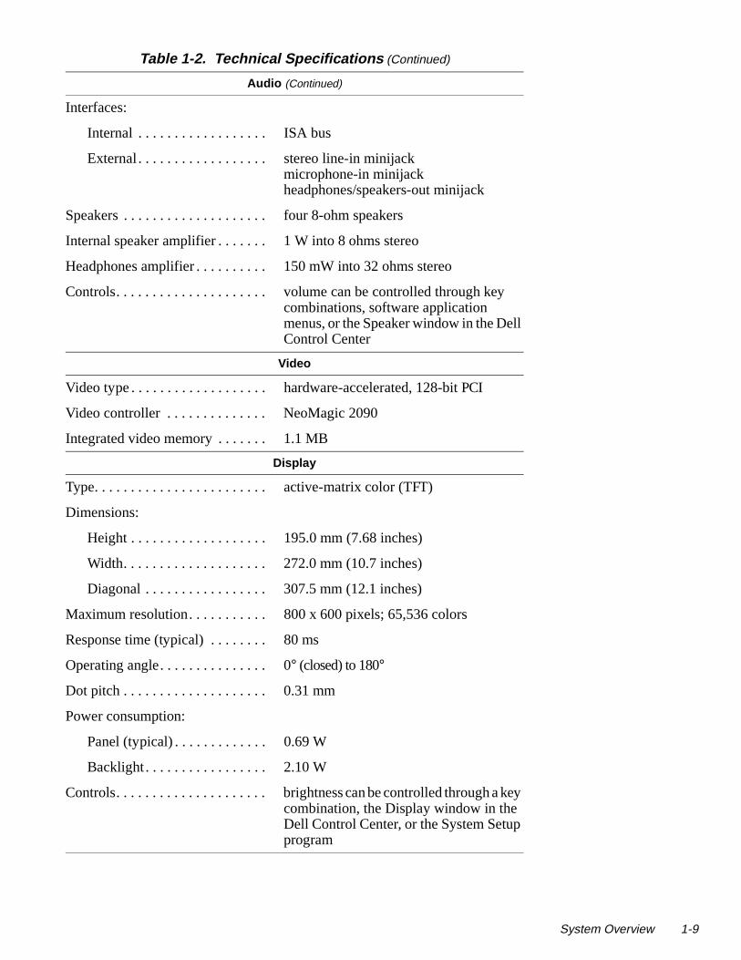
Technical SpecificationsTable 1-2. Technical Specifications
Microprocessor
Microprocessor type . . . . . . . . . . . Intel Pentium microprocessor
Microprocessor speed . . . . . . . . . . 150 MHz
Bus architecture . . . . . . . . . . . . . . PCI
Internal cache memory . . . . . . . . . 16 KB
External cache memory. . . . . . . . . 256 KB pipelined-burst SRAM
Math coprocessor . . . . . . . . . . . . . internal to the microprocessor
Chip Set and Bus
System chip set . . . . . . . . . . . . . . . Pico Power Vesuvius-LS Core Logic
Microprocessor data bus width . . . 64 bits
DRAM bus width . . . . . . . . . . . . . 64 bits
Address bus width. . . . . . . . . . . . . 32 bits
Security EEPROM . . . . . . . . . . . . 256 bytes
Flash EPROM. . . . . . . . . . . . . . . . 256 KB
Local bus. . . . . . . . . . . . . . . . . . . . 60 MHz
PCI bus . . . . . . . . . . . . . . . . . . . . . 30 MHz
PC Card
PC Card controller . . . . . . . . . . . . Texas Instruments PCI1130 CardBuscontroller
PC Card connectors . . . . . . . . . . . two (supports type I and type II cardsany combination; type III cards can be used only with type I or type II cards)
Cards supported . . . . . . . . . . . . . . 3.3-V and 5-V
PC Card connector size. . . . . . . . . 68 pins
Data width (maximum). . . . . . . . . 32 bits
Memory
Architecture . . . . . . . . . . . . . . . . .EDO memory1
Memory module sockets . . . . . . . . two1 The system supports fast-page-mode memory modules for memory upgrades.
System Overview 1-7

1-8 Dell Latitude XPi CD S
l,
es )
Memory (Continued)
Memory module type and capacities . . . . . . . . . . . . . . . . . . . 8- and 16-MB fast-page mode
Standard RAM . . . . . . . . . . . . . . . 16 MB (EDO) on system board
Maximum RAM . . . . . . . . . . . . . . 48 MB
Memory access time:
tRAC . . . . . . . . . . . . . . . . . . . 70 ns
tCAC . . . . . . . . . . . . . . . . . . . 20 ns
BIOS address . . . . . . . . . . . . . . . . F000:0000
Connectors
Serial (DTE) . . . . . . . . . . . . . . . . . one 9-pin connector; 16550-compatible,16-byte buffer
Parallel . . . . . . . . . . . . . . . . . . . . . one 25-hole connector; unidirectionabidirectional, EPP 1.9, or ECP
Monitor. . . . . . . . . . . . . . . . . . . . . one 15-hole connector
PS/2 . . . . . . . . . . . . . . . . . . . . . . . one 6-pin mini-DIN (this connector donot support more than one device at a time
Infrared . . . . . . . . . . . . . . . . . . . . . two ports compatible with IrDA Standard 1.1 (Fast IR)
Audio . . . . . . . . . . . . . . . . . . . . . . microphone-inline-in/audio-inheadphones/speakers
Advanced Port Replicator . . . . . . 200-pin connector
Audio
Audio type . . . . . . . . . . . . . . . . . . SoundBlasterPro-compatible 3.01 voice and music functions
Audio controller . . . . . . . . . . . . . . ES1888 ES690 wavetable music synthesizer, ES938 3D audio spatializer
Stereo conversion . . . . . . . . . . . . . 16 bit (analog-to-digital and digital-to-analog)
FM music synthesizer. . . . . . . . . . 20-voice, 72-operator
Table 1-2. Technical Specifications (Continued)
ervice Manual
l
key
Audio (Continued)
Interfaces:
Internal . . . . . . . . . . . . . . . . . . ISA bus
External . . . . . . . . . . . . . . . . . . stereo line-in minijackmicrophone-in minijackheadphones/speakers-out minijack
Speakers . . . . . . . . . . . . . . . . . . . . four 8-ohm speakers
Internal speaker amplifier . . . . . . . 1 W into 8 ohms stereo
Headphones amplifier . . . . . . . . . . 150 mW into 32 ohms stereo
Controls. . . . . . . . . . . . . . . . . . . . . volume can be controlled through keycombinations, software application menus, or the Speaker window in the DelControl Center
Video
Video type . . . . . . . . . . . . . . . . . . . hardware-accelerated, 128-bit PCI
Video controller . . . . . . . . . . . . . . NeoMagic 2090
Integrated video memory . . . . . . . 1.1 MB
Display
Type. . . . . . . . . . . . . . . . . . . . . . . . active-matrix color (TFT)
Dimensions:
Height . . . . . . . . . . . . . . . . . . . 195.0 mm (7.68 inches)
Width. . . . . . . . . . . . . . . . . . . . 272.0 mm (10.7 inches)
Diagonal . . . . . . . . . . . . . . . . . 307.5 mm (12.1 inches)
Maximum resolution. . . . . . . . . . . 800 x 600 pixels; 65,536 colors
Response time (typical) . . . . . . . . 80 ms
Operating angle. . . . . . . . . . . . . . . 0° (closed) to 180°
Dot pitch . . . . . . . . . . . . . . . . . . . . 0.31 mm
Power consumption:
Panel (typical) . . . . . . . . . . . . . 0.69 W
Backlight . . . . . . . . . . . . . . . . . 2.10 W
Controls. . . . . . . . . . . . . . . . . . . . . brightness can be controlled through acombination, the Display window in the Dell Control Center, or the System Setupprogram
Table 1-2. Technical Specifications (Continued)
System Overview 1-9

1-10 Dell Latitude XPi CD S
nd
ding
Keyboard
Number of keys . . . . . . . . . . . . . . 85 (U.S., Canada, Korea, Thailand, alocations that use traditional Chinese); 86 (Europe); 87 (Japan)
Key travel . . . . . . . . . . . . . . . . . . . 3.0 ± 0.5 mm (0.12 ± 0.02 inch)
Key spacing . . . . . . . . . . . . . . . . . 18.25 mm (0.72 inch)
Layout. . . . . . . . . . . . . . . . . . . . . . QWERTY, AZERTY, Kanji
Battery
Type . . . . . . . . . . . . . . . . . . . . . . . lithium ion
Dimensions:
Height . . . . . . . . . . . . . . . . . . . 20.5 mm (0.81 inch)
Depth . . . . . . . . . . . . . . . . . . . 152.75 mm (6.01 inches)
Width . . . . . . . . . . . . . . . . . . . 78.5 mm (3.09 inches)
Weight. . . . . . . . . . . . . . . . . . . . . . 0.41 kg (0.9 lb)
Voltage . . . . . . . . . . . . . . . . . . . . . 14.4 VDC
Capacity . . . . . . . . . . . . . . . . . . . . 36 WH
Charge time (approximate):2
Computer on . . . . . . . . . . . . . . 2.5 hours
Computer off . . . . . . . . . . . . . 1.5 hours
Operating time (approximate, with no power management features enabled)2. . . . . . . . . . . . . . . . . . . . 2 to 3.5 hours (without a CD-ROM drive
in use)
Life span (approximate)2 . . . . . . . 400 discharge/charge cycles
Temperature range:
Charge . . . . . . . . . . . . . . . . . . 10° to 40°C (50° to 104°F)
Discharge . . . . . . . . . . . . . . . . 10° to 40°C (50° to 104°F)
Storage . . . . . . . . . . . . . . . . . . –40° to 65°C (–40° to 149°F)2 Battery performance features such as charge time, operating time, and life span can vary accor
to the conditions under which the computer and battery are used.
Table 1-2. Technical Specifications (Continued)
ervice Manual

ap
)
Battery (Continued)
NiCad reserve battery:
Voltage . . . . . . . . . . . . . . . . . . 7.2 V
Operating time (approximate) . . . . . . . . . . . . . 2 minutes (if computer is in battery sw
mode); 40 days (if power is turned off)
AC Adapter
Input voltage . . . . . . . . . . . . . . . . . 90 to 135 VAC and 164 to 264 VAC
Input current (maximum) . . . . . . . 1.2 A and 0.6 A
Input frequency . . . . . . . . . . . . . . . 47 to 63 Hz
Output current . . . . . . . . . . . . . . . . 4.5 A (maximum); 3.5 A (continuous)
Rated output voltage . . . . . . . . . . . 18.5 VDC
Height . . . . . . . . . . . . . . . . . . . . . . 27.94 mm (1.1 inches)
Width. . . . . . . . . . . . . . . . . . . . . . . 58.42 mm (2.3 inches)
Depth. . . . . . . . . . . . . . . . . . . . . . . 133.35 mm (5.25 inches)
Weight (with cables) . . . . . . . . . . 0.4 kg (0.89 lb)
Temperature range:
Operating . . . . . . . . . . . . . . . . 0° to 40°C (32° to 104°F)
Storage . . . . . . . . . . . . . . . . . . -40° to 70°C (-40° to 158°F)
CD-ROM Drive 3
Disc size . . . . . . . . . . . . . . . . . . . . 8 cm and 12 cm (no adapter required
Data transfer rate:
Sustained. . . . . . . . . . . . . . . . . 900 KB/sec (mode 2 disc)
Burst . . . . . . . . . . . . . . . . . . . . 14.4 MB/sec (PIO mode 3)
Seek time:
Random. . . . . . . . . . . . . . . . . . 200 m/sec
Full-stroke. . . . . . . . . . . . . . . . 500 m/sec3 The CD-ROM drive in your computer may have different specifications.
Table 1-2. Technical Specifications (Continued)
System Overview 1-11

1-12 Dell Latitude XPi CD S
CD-ROM Drive 3 (Continued)
Access time:
Random . . . . . . . . . . . . . . . . . 250 m/sec
Full-stroke . . . . . . . . . . . . . . . 550 m/sec
Memory buffer . . . . . . . . . . . . . . . 128 KB
Physical (Computer)
Height . . . . . . . . . . . . . . . . . . . . . . 63.0 mm (2.48 inches)
Width . . . . . . . . . . . . . . . . . . . . . . 280.9 mm (11.06 inches)
Depth . . . . . . . . . . . . . . . . . . . . . . 233.5 mm (9.19 inches)
Weight (with battery and hard-disk drive) . . . . . . . . . . . . . . 3.29 kg (7.26 lb)
Environmental
Temperature:
Operating . . . . . . . . . . . . . . . . 10° to 40°C (50° to 104°F)
Storage . . . . . . . . . . . . . . . . . . -40° to 65°C (-40° to 149°F)
Relative humidity (maximum):
Operating . . . . . . . . . . . . . . . . 90% (noncondensing)
Storage . . . . . . . . . . . . . . . . . . 95% (noncondensing)
Maximum vibration:
Operating . . . . . . . . . . . . . . . . 0.51 GRMS, using a random-vibrationspectrum that simulates truck shipment
Storage . . . . . . . . . . . . . . . . . . 1.1 GRMS, using a random-vibrationspectrum that simulates air/truck shipment
3 The CD-ROM drive in your computer may have different specifications.
Table 1-2. Technical Specifications (Continued)
ervice Manual

n or
)
Environmental (Continued)
Maximum shock:4
Operating . . . . . . . . . . . . . . . . 152.4 cm/sec (60 inches/sec) (less thaequal to a pulse width of 2 ms)
Storage . . . . . . . . . . . . . . . . . . 203.2 cm/sec (80 inches/sec)(less than or equal to a pulse width of 2 ms
Altitude (maximum):
Operating . . . . . . . . . . . . . . . . 3048 m (10,000 ft)
Storage . . . . . . . . . . . . . . . . . . 10,600 m (35,000 ft)4 Measured with the hard-disk drive in head-parked position.
Table 1-2. Technical Specifications (Continued)
System Overview 1-13

1-14 Dell Latitude XPi CD S
ervice Manual
Chapter 2Initial Procedures
m- or om-in this
o
riate llow
re.
orrec-r
This chapter describes initial procedures that can help you diagnose a coputer problem. These procedures can often reveal the source of a problemindicate the correct starting point for troubleshooting the computer. Dell recmends that you perform these procedures in the order they are presented manual.
Initial User ContactWhen you first contact a user who has a computer problem, ask the user tdescribe the problem and the conditions under which it occurs. A verbal description can often indicate the cause of a problem or indicate the approptroubleshooting procedure to use. After the user describes the problem, fothese steps:
1. Ask the user to back up any data on the hard-disk drive if the system’scondition permits.
See “Maintaining Your Computer” in the online System User’s Guide.
2. Ask the user to try to duplicate the problem by repeating the operations he or she was performing at the time the problem occurred.
Can the user duplicate the problem?
Yes. Proceed to step 3.
No. Proceed to the next section, “Visual Inspection.”
3. Observe the user to determine whether he or she is making an error, such as typing an incorrect key combination or entering a command incorrectly.
Is the problem a result of user error?
Yes. Instruct the user in the proper procedure, or direct him or her to theappropriate user documentation for a description of the correct procedu
No. Proceed to the next section, “Visual Inspection.”
Visual InspectionThe visual inspection consists of a quick inspection of the exterior of the computer and any attached peripherals, including making any necessary ctions. For information about the proper removal and installation of compute
Initial Procedures 2-1

2-2 Dell Latitude XPi CD S
mov-
ly, n:
— ey to
turn e
ton
n
nd
-
e.
uter
ging ing
components, as instructed in the following procedures, see Chapter 4, “Reing and Replacing Parts.”
To perform a visual inspection, follow these steps:
1. Turn off any attached peripherals.
2. Determine the present power state of the computer.
Look at the indicators to determine which of the following conditions appand then turn off the computer, taking the actions listed for that conditio
• Power/suspend indicator is blinking approximately every 8 secondsThe computer is in suspend mode. Open the display and press any kreturn the computer to the power-on state. If the computer does noton, press <FN><B> to return from battery-swap mode. Then slide thpower button to turn off the computer.
• Low-battery indicator is on or blinking — A low-battery warning occurred; open the display and slide the power button to turn off thecomputer.
• Low-battery and charging indicators are both blinking — A defectivebattery is detected or the computer is too warm; slide the power butto turn off the computer.
• All indicators remain off — The computer is already turned off or is isuspend-to-disk mode.
3. Verify that the exterior of the computer is free of any obvious physical damage.
4. If the computer is operating from an AC adapter, verify the following:
• The AC adapter’s AC power cable is connected to the AC adapter athe power source.
• The AC adapter’s DC power cable is properly connected to the computer’s DC power input connector.
• The AC adapter and cables are free of any obvious physical damag
NOTE: If the charging indicator and low-battery indicator flash continu-ously while the computer is connected to AC power, disconnect the compfrom AC power and move it to a cooler location. When the computer hascooled to room temperature, reconnect it to AC power and continue charthe battery. If the computer is not allowed to cool, the battery stops chargbefore it reaches full capacity.
CAUTION: Before you proceed with the visual inspection, ensure thatthe user has saved all open files and exited all open application programsif possible.
ervice Manual

ctor
of
cu-
n-
ppro-
ter-
phys-
5. If the computer is operating from battery power, remove the main bat-tery assembly, verify that it is free of any obvious physical damage, andthen reinsert the battery assembly into its compartment.
6. Turn off the computer. Remove the hard-disk drive, verify that it is free of any obvious physical damage, and then reinsert the drive into its compartment.
7. Remove any installed PC Cards from the PC Card slot, verify that they are free of any obvious physical damage, and then reinsert the card(s) into the PC Card slot.
8. Remove any memory modules from the memory compartment, verify that they are free of any obvious damage, and then reinstall the mem-ory modules.
9. Open the display assembly, and verify that it is free of any obvious physical damage.
10. Verify that the internal keyboard is free of any obvious physical dam-age and that its keys operate freely.
11. Verify that the trackball and its associated switches operate freely.
12. If an external monitor is connected, verify the following:
• The monitor’s interface cable is properly attached to the VGA conneon the I/O panel.
• The monitor’s power cable is attached to a power source and is freeany obvious physical damage.
• The monitor’s controls are set according to the instructions in the domentation for the monitor.
• The monitor and its interface cable are free of any obvious physicaldamage.
13. If an external mouse is connected, verify the following:
• The mouse is properly connected to the keyboard/keypad/mouse conector on the computer’s I/O panel.
• The mouse and its cable are free of any obvious physical damage.
• The mouse’s ball and push buttons operate freely.
14. For any attached serial or parallel devices, verify the following:
• The device’s interface cable connector is correctly attached to the apriate port connector on the computer’s I/O panel.
• The captive screws that secure the connectors at each end of the inface cable are secure enough to ensure a firm connection.
• The attached device and its interface cable are free of any obvious ical damage.
Initial Procedures 2-3
2-4 Dell Latitude XPi CD S
boot ing,
ays puter. or
oot
tors ther he
rror
le
or o
15. Turn on any attached peripherals and then the computer.
Does the problem reoccur?
Yes. Proceed to the next procedure, “Observing the Boot Routine.”
No. No further steps are necessary.
Observing the Boot RoutineAfter you perform a visual inspection as described in the previous section, the computer from a diagnostics diskette and, while the boot routine is runnobserve the computer for any indications of problems.
NOTE: To prevent possible damage to the original diagnostics diskette, alwuse a backup copy of the diagnostics diskette when servicing a user’s comDell recommends that users make copies of the Dell diagnostics diskette. Finstructions, see “Before You Start Testing” in Chapter 4 of the Reference and Troubleshooting Guide.
To observe the boot routine, follow these steps:
1. Turn off the computer and any attached peripherals.
2. Insert a diagnostics diskette into the diskette drive. Turn on all periph-erals and then the computer.
3. Watch the indicators on the top of the keyboard. After all three indica-tors flash momentarily, the Num Lock indicator should light up and remain on.
Do these indicators light up within approximately 10 seconds after the broutine starts?
Yes. Proceed to step 4.
No. Troubleshoot the power subsystem.
4. While the boot routine is running, observe the computer for any of the following:
• Diskette-drive and hard-disk drive access indicators — These indicalight in response to data being transferred to or from the drives. If eiof these indicators fail to light during the boot routine, troubleshoot tdiskette-drive or hard-disk drive subsystem, as appropriate.
• Beep codes — A beep code is a series of beeps that indicates an econdition. If the computer emits a beep code, go to Table 3-1.
NOTE: The computer beeps once during the boot routine. This singbeep is normal and is not a beep code.
• System error messages — These messages can indicate problemsprovide status information. If a system error message displays, go tTable 3-2.
ervice Manual

upt of sible
fail-ight
ot-
r lead em,
5. Observe the display for the Diagnostics Menu.
Does the Diagnostics Menu display?
Yes. See “Running the Dell Diagnostics” in Chapter 3.
No. Proceed to step 6.
6. Insert another copy of the diagnostics diskette into the diskette drive, and reboot the computer.
Does the Diagnostics Menu display?
Yes. See “Running the Dell Diagnostics” in Chapter 3.
No. Proceed to the next section, “Eliminating Resource Conflicts.”
Eliminating Resource ConflictsDevices within the computer may require dedicated memory spaces, interrlevels, or DMA channels, all of which must be allocated during installation the devices. Because a device may be installed at a different time, it is posthat the same resource is assigned to two or more devices.
Resource conflicts can result in disorderly or erratic computer operation orure of the computer to operate at all. If you suspect that resource conflicts mexist, check the computer and reassign the resources as necessary.
For more information about resolving conflicts, see Chapter 3, “Troubleshoing Your Computer,” in the Reference and Troubleshooting Guide.
Getting HelpIf none of the procedures in this chapter reveal the source of the problem oto the proper troubleshooting steps for determining the source of the problcall Dell for technical assistance. For instructions, see Chapter 5, “Getting Help,” in the Reference and Troubleshooting Guide.
Initial Procedures 2-5

2-6 Dell Latitude XPi CD S
ervice Manual
Chapter 3Beep Codes and Error Messages
occur m- code ach
sages e
er iden-s r that e the
This chapter describes beep codes and system error messages that can during computer start-up or, in the case of some failures, during normal coputer operation. The tables in this chapter list faults that can cause a beepor system error message to occur and the probable causes of the fault in ecase.
If a faulty computer does not emit beep codes or display system error mesto indicate a failure, use the Dell diagnostics to help isolate the source of thproblem. See “Running the Dell Diagnostics” found later in this chapter.
POST Beep Codes If the display cannot display error messages during the POST, the computmay emit a series of beeps that identifies the problem or that can help youtify a faulty component or assembly. The following table lists the beep codethat may be generated during POST. Most beep codes indicate a fatal errorequires replacement of the system board or other corrective actions beforcomputer can operate.
Table 3-1. POST Beep Codes
Beep Code Error Probable Causes
1-1-3 NVRAM write/read failure
BIOS corrupted; system board faulty
1-1-4 ROM BIOS checksum failure
BIOS corrupted; system board faulty
1-2-1 Programmable interval timer failure
System board faulty
1-2-2 DMA initialization failure
System board faulty
1-2-3 DMA page register write/read failure
System board faulty
1-3-1through2-4-4
Installed memory module(s) not being properly identified or used
Memory module improperly seated or system memory controller faulty (system board faulty)
Beep Codes and Error Messages 3-1

3-2 Dell Latitude XPi CD S
3-1-1
3-1-2
Slave DMA register failure
Master DMA register failure
System board faulty
3-1-3
3-1-4
Master interrupt mask register failure
Slave interrupt mask register failure
System board faulty
3-2-4 Keyboard controller test failure
Keyboard assembly faulty or systemboard faulty
3-3-4
3-4-1
3-4-2
Display memory test failure
Display initialization failure
Display retrace test failure
System board faulty
4-2-1
4-2-2
4-2-3
4-2-4
No timer tick
Shutdown failure
Gate A20 failure
Unexpected interrupt in protected mode
System board faulty
4-3-1 Memory failure above address 0FFFFh
Memory module improperly seated or system memory controller faulty (system board faulty)
4-3-3 Timer chip counter 2 failure
System board faulty
4-3-4 Time-of-day clock stopped
Reserve battery faulty or system board faulty
4-4-1 Serial port failure System board faulty
4-4-2 Parallel port test failure System board faulty
4-4-3 Math coprocessor failure
System board faulty
Table 3-1. POST Beep Codes (Continued)
Beep Code Error Probable Causes
ervice Manual

may
System Error MessagesThe following table lists (in alphabetical order) system error messages thatappear on the display during the boot routine or during normal computer operation.
5-1-1
5-1-2
5-1-3
5-2-1
5-2-2
5-2-3
5-2-4
System power-management interrupt initialization failure
BIOS shadowing failure
Video BIOS shadowing failure
Keyboard controller download failure
CPU stepping failure
System board failure
Setup decompression and shadowing failure
System board faulty
Table 3-2. System Error Messages
Message Definition Probable Causes
Auxiliary device failure
Integrated trackball or external PS/2 mouse failed.
Integrated trackball or external PS/2 mouse faulty.
Bad command or File Name
Command entered does not exist or is not in pathname specified.
Bad command or filename entered.
Cache disabled due to failure
Microprocessor’s internal cache memory failed.
System board faulty.
Data error Diskette or hard-disk drive cannot read the data.
Faulty diskette/tape drive subsystem or hard-disk drive sub-system.
Table 3-1. POST Beep Codes (Continued)
Beep Code Error Probable Causes
Beep Codes and Error Messages 3-3

3-4 Dell Latitude XPi CD S
Decreasing available memory
Informational message indicating memory is fail-ing (usually preceded by memory error message).
One or more DIMMs faulty or improperly seated.
Disk C: failed initialization
Hard-disk drive failed to initialize.
Hard-disk drive data in System Setup does not match installed hard-disk drive, or hard-disk drive faulty.
System files missing or corrupted.
Diskette drive 0seek failure
Diskette read failure
System cannot read dis-kette in diskette drive.
Diskette faulty or incorrectly inserted in drive.
System Setup con-tains incorrect settings.
Diskette drive inter-face loose or faulty.
Diskette drive faulty.
Diskette sub-system reset failed
Diskette subsystem failed to respond to reset com-mand from computer.
System board faulty.
Diskette write-protected
Diskette is write-protected, operation cannot be completed.
Diskette write-protected.
Drive not ready The diskette may be missing from or improperly installed in the diskette drive.
Defective or unfor-matted diskette.
Error reading PCMCIA card
Computer cannot identify PC Card.
PC Card faulty, improperly seated, or improperly con-figured. System board faulty.
PC Card software faulty or incorrectly installed.
Table 3-2. System Error Messages (Continued)
Message Definition Probable Causes
ervice Manual

Extended memory size has changed
Amount of memory recorded in NVRAM not matching memory installed in computer.
One or more mem-ory module(s) faulty or improperly seated.
Gate A20 failure Computer cannot enable protective mode.
One or more mem-ory module(s) faulty or improperly seated.
System board faulty.
General failure Message indicates sys-tem failure.
Operating system unable to carry out the command.
Hard-disk drive configuration error
Computer cannot identify hard-disk drive type.
Installed hard-disk drive not compatible with computer.
Hard-disk drive controller failure 0
Hard-disk drive or control-ler not responding to commands from computer.
System board faulty.
Hard-disk drive controller failure 0
The CD-ROM drive does not respond to commands from the computer.
System board faulty.
Hard-disk drive failure
Hard-disk drive read failure
Hard-disk drive not responding to commands from computer.
Computer needs rebooting.
Hard-disk drive faulty.
Invalid configuration information — please run System Setup program
System Setup contains invalid settings.
Incorrect settings in System Setup.
Reserve battery weak or depleted.
Keyboard con-troller failure
Keyboard controller not responding.
Cable or connector loose, or keyboard faulty.
Keyboard clock line failure
Keyboard data line failure
Keyboard not responding. Cable or connector loose, or keyboard faulty.
Table 3-2. System Error Messages (Continued)
Message Definition Probable Causes
Beep Codes and Error Messages 3-5

3-6 Dell Latitude XPi CD S
Keyboard stuck key failure
Keyboard key(s) jammed. For external key-board or keypad, cable or connector loose or keyboard faulty.
For built-in key-board, keyboard faulty.
For either keyboard, key may have been pressed while com-puter was booting.
Memory address line failure at address , read value expecting value
Memory control logic not operating properly.
Installed memory module faulty or improperly seated.
Memory alloca-tion error
The software in use conflicts with the operating system, an application program, or a utility
Faulty application program
Table 3-2. System Error Messages (Continued)
Message Definition Probable Causes
ervice Manual

Memory data line failure at address , read value expecting value
Memory double word logic fail-ure at a ddress , read value expecting value
Memory odd/even logic failure at address , read value expecting value
Memory write/read failure at address , read value expecting value
Memory not operating properly.
Installed memory module faulty or improperly seated.
No boot device available
Computer not recognizing diskette drive or hard-disk drive from which it is try-ing to boot.
No boot device available.
No boot sector on hard-disk drive
No boot sector on hard-disk drive.
Operating system boot files missing or corrupted.
No timer tick interrupt
Timer on system board malfunctioning.
System board faulty.
Non-system disk or disk error
Not a boot dis-kette
Unable to boot from hard-disk drive or diskette drive.
No operating system files on hard-disk drive or diskette.
Optional ROM bad checksum
ROM in external device failed.
Optional ROM in external device faulty.
Sector not found MS-DOS® unable to locate a sector on dis-kette or hard-disk drive.
Bad sector or cor-rupted FAT on diskette or hard-disk drive.
Table 3-2. System Error Messages (Continued)
Message Definition Probable Causes
Beep Codes and Error Messages 3-7

3-8 Dell Latitude XPi CD S
:
m
t
Running the Dell Diagnostics The diagnostics contains tests that aid in troubleshooting the computer. If needed, see Chapter 4, “Running the Dell Diagnostics,” in the Reference and Troubleshooting Guide. The diagnostics diskette contains the following test groups
• RAM — Tests the main memory
• System Set — Tests the system board’s primary functions
• Video — Tests the video subsystem
• Keyboard — Tests the keyboard subsystem
• Mouse — Tests the mouse/trackball subsystem
• Diskette Drives — Tests the diskette drive subsystem
• Hard-Disk Drives (Non-SCSI) — Tests the IDE hard-disk drive subsyste
• IDE CD-ROM Drives — Tests the CD-ROM drive subsystem
Seek error MS-DOS unable to find specific track on diskette or hard-disk drive.
Defective diskette or hard-disk drive.
Shutdown fail-ure
Microprocessor unable to reset.
System board faulty.
Time-of-day clock lost power
Time-of-day clock stopped
System clock stopped. Reserve battery losits charge.
Time-of-day not set—please run the System Setup program.
Time or date stored in RTC does not match system clock.
Reserve battery lost its charge.
System board faulty.
Timer chip counter 2 failed
Timer circuit on system board malfunctioning.
System board faulty.
Unexpected interrupt in protected mode
Keyboard/mouse control-ler malfunctioning, or memory module(s) not responding.
One or more mem-ory module(s) faulty or improperly seated.
Warning! Bat-tery is criti-cally low.
Main battery has lost its charge.
Main battery needs recharging.
Table 3-2. System Error Messages (Continued)
Message Definition Probable Causes
ervice Manual

into
a oads,
e
os-t to
iso-
s
• Serial Ports — Tests the serial communication port
• Parallel Ports — Tests the parallel communication port
• SCSI Devices — Tests the SCSI controller in the Advanced Port Replicator
• Network Interface — Tests the network controller in the Advanced PortReplicator
• Serial Infrared — Tests the IrDA communications port
• Audio — Tests the built-in sound subsystem
To start the diagnostics, turn off the computer, insert a diagnostics diskettethe diskette drive, and then turn on the computer.
Starting the diagnostics causes the Dell logo screen to appear, followed bymessage indicating that the diagnostics is loading. Before the diagnostics la program tests the portion of main memory (RAM) required for loading thediagnostics. If a main memory error is detected, a message appears on thscreen telling you which memory address failed.
If no errors are found in main memory, the diagnostics loads and the Diagntics Menu appears. This menu lets you choose the following options or exithe MS-DOS prompt:
• RUN QUICK TESTS — Runs selected tests from all test groups to quicklylocate the failure or to indicate where further testing may be needed to late a failure
• RUN ALL TESTS — Runs all tests for a thorough test of the computer
• RUN SPECIFIC TESTS — Tests a particular area or subsystem
CAUTION: To prevent possible damage to the original diagnostics dis-kette, always use a backup copy of the diagnostics diskette when servicing auser’s system. If the user has not already made a backup copy of the diagnosticdiskette, do so before you run the diagnostics.
Beep Codes and Error Messages 3-9

3-10 Dell Latitude XPi CD S
ervice Manual
Chapter 4Removing and Replacing Parts
d
ing:
ipher-
ething with . Also, rela-.
This chapter provides instructions for removing and replacing field-replaceable components, assemblies, and subassemblies. For removal anreplacement procedures for factory-replaceable parts, see Appendix A,“Factory Repair Parts.”
Unless otherwise noted, each procedure in this chapter assumes the follow
• The computer and any attached peripherals are turned off, and the perals are disconnected from the I/O panel on the back of the computer.
• A part can be replaced by performing the removal procedure in reverseorder.
When the display assembly is open nearly 180 degrees, use a book or somsimilar to support the display assembly. The angle of the display assemblyrespect to the bottom case should never be allowed to exceed 180 degreeswhen performing the procedures in this chapter, the locations or directionstive to the computer are as shown in Figure 4-1 unless otherwise specified
Figure 4-1. Computer Orientation
right side left side
back of computer
front of computer
Removing and Replacing Parts 4-1

4-2 Dell Latitude XPi CD S
ol-
Recommended ToolsMost of the procedures in this guide require the use of one or more of the flowing tools:
• Small flat-blade screwdriver
• Jeweler’s screwdriver set
• Number 1 magnetized Phillips-head screwdriver
• Number 2 magnetized Phillips-head screwdriver
• Chip-removal tool
• Wrist grounding strap
• Small plastic scribe
• Nut drivers
Precautionary Measures
Before you start to work on the computer, perform the following steps:
1. Turn off the computer and any attached peripherals.
NOTE: Make sure the computer is turned off and not in suspend-to-diskmode. See “Controlling Computer Power” in Chapter 1.
2. Disconnect the computer and any attached peripherals from AC power sources to reduce the potential for personal injury or shock. Also dis-connect any telephone or telecommunications lines from the computer.
3. Remove the main battery assembly from the battery compartment.
Slide the battery compartment door downward until it stops (about 3/16 of an inch). Slide the main battery assembly out.
WARNING: FOR YOUR PERSONAL SAFETY AND PROTECTIONOF THE EQUIPMENT, PERFORM THE FOLLOWING STEPS INTHE SEQUENCE LISTED.
ervice Manual
tric- of
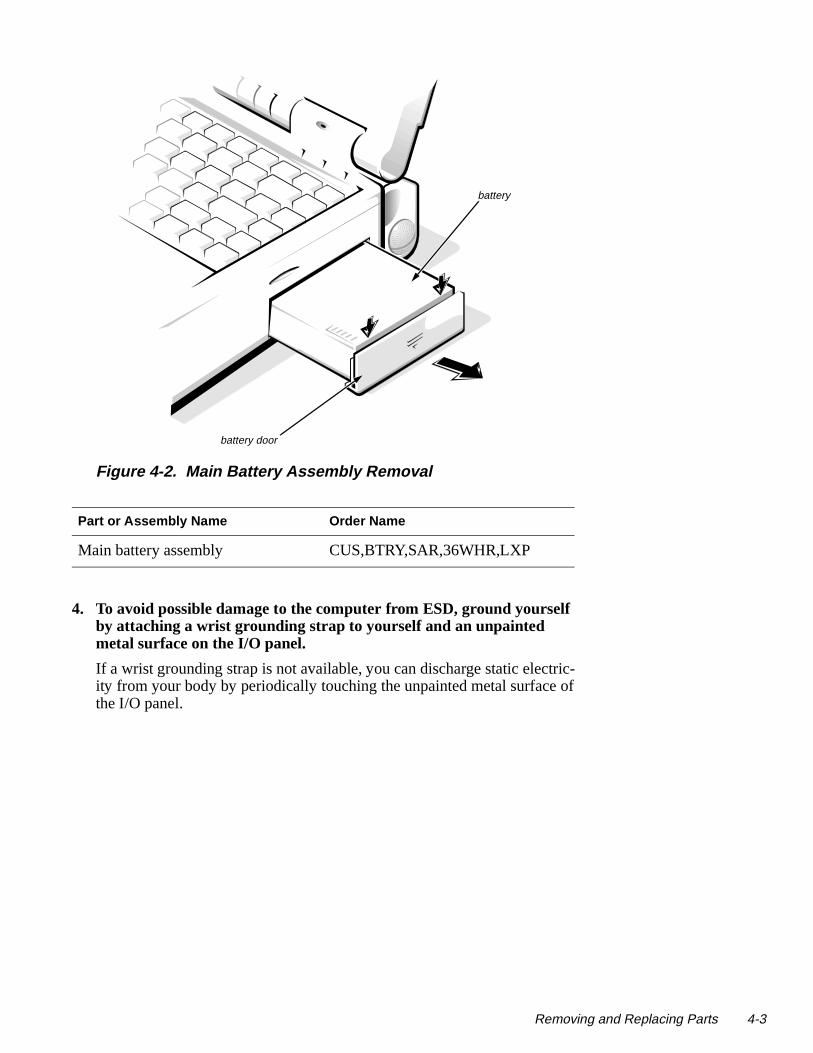
Figure 4-2. Main Battery Assembly Removal
4. To avoid possible damage to the computer from ESD, ground yourself by attaching a wrist grounding strap to yourself and an unpainted metal surface on the I/O panel.
If a wrist grounding strap is not available, you can discharge static elecity from your body by periodically touching the unpainted metal surfacethe I/O panel.
Part or Assembly Name Order Name
Main battery assembly CUS,BTRY,SAR,36WHR,LXP
battery door
battery
Removing and Replacing Parts 4-3

4-4 Dell Latitude XPi CD S
is tra-
Screw Identification and Tightening
Figure 4-3. Screw Identification
The removal procedure illustrations provide the correct screw length in parentheses next to the screw’s label. Also, a graphic for that length screwincluded in the illustration. Match the actual screw to the graphic in the illustion to check for correct length.
CAUTION: It is essential that the correct length screw be used whenreinstalling a screw. Otherwise, hardware damage could result. Makesure that the screw is properly aligned with its corresponding hole, andavoid overtightening.
A6 (35 mm)
(screw A6 is 35 mm)
match length here35 mm
ervice Manual

con-o
to d
y
ZIF Connectors
Figure 4-4. Disconnecting an Interface Cable
Some of the computer’s interface connectors are zero insertion force (ZIF)nectors. These connectors are not removable, but they must be released tdisconnect a cable from them.
To disconnect an interface cable from a ZIF connector, follow these steps:
1. Insert a small flat-blade screwdriver or a chip-removal tool under the movable part of the connector.
If a small flat-blade screwdriver is unavailable, use a chip-removal tool carefully pry up on first one end of the movable part of the connector anthen the other end.
2. Pull gently upward on the movable part of the connector until it releases the interface cable.
3. Grasp the interface cable and pull it out of the connector.
To reconnect an interface cable to a ZIF connector, follow these steps:
1. Use a flat-blade screwdriver or chip-removal tool to open the movable part of the ZIF connector.
2. Orient the end of the interface cable with the ZIF connector, and insert the end of the cable into the connector.
3. While holding the cable in place, close the ZIF connector.
To ensure a firm connection, make sure the ZIF connector is completelclosed.
CAUTION: The ZIF connectors are fragile. To avoid damage, do notapply too much pressure to the movable part of the connector.
movable part of connector; do not remove
Removing and Replacing Parts 4-5

4-6 Dell Latitude XPi CD S
ly ch f the
d
foot
ry
Field-Replaceable Parts and Assemblies
Figure 4-5. Exploded View—Computer
The computer is divided into three major assemblies: the palmrest assemb(which contains the keyboard and the trackball), the display assembly (whicontains the LCD), and the bottom case assembly (which contains many oremovable parts).
display assembly
keyboard
I/O panel dust cover
dust cover for the AdvancePort Replicator connector
right tilt-support
main batte
left tilt-support foot
PC Card
memory compartment cover CD-ROM/diskette drive assembly
palmrest assembly
bottom case assembly
superpart assembly
trackball assembly
CD-ROM EMI clip
keyboard EMI clip
hard-disk drive assembly
ervice Manual

ble list-
Fac-
pen.
The following subsections provide instructions for removing and replacing these parts and assemblies. Some of the instructions are preceded by a taing the Dell order name for the part or assembly being replaced. A more detailed breakdown of parts and assemblies can be found in Appendix A, “tory Repair Parts.”
Hard-Disk Drive Assembly
Figure 4-6. Hard-Disk Drive Assembly Removal
To remove the hard-disk drive assembly, follow these steps:
1. Slide the drive latch toward the front of the computer to release the hard-disk drive assembly from the hard-disk drive bay.
The latch is on the left-front corner of the computer.
2. Grasp the drive door and pull the drive out of the computer.
When reinserting the drive into the drive bay, ensure that the drive latch is oThen slide the drive completely into the hard-disk drive bay.
Part or Assembly Name Order Name
Hard-disk drive assembly CUS,HD,xxxxx,yyMM,zzz,LXP*
* Substitute the drive capacity for xxxxx, the drive height for yy, and the manufacturer for zzz.
CAUTION: The hard-disk drive is very sensitive to shock. Handle theassembly with care and avoid dropping it even from a height of 1 inch.
drive latch
front of computer
drive door
PC Card slot
hard-disk drive
Removing and Replacing Parts 4-7

4-8 Dell Latitude XPi CD S
Memory Compartment Cover
Figure 4-7. Memory Compartment Cover Removal
To remove the memory compartment cover, follow these steps:
1. Turn the computer upside down on the work surface.
2. To release the memory compartment cover, press down on the identa-tion in the edge of the cover, and then slide the cover towards the edgeof the computer.
Part or Assembly Name Order Name
Memory compartment cover CVR,MEM,LXPiCD
CAUTION: Make sure the work surface is clean to prevent scratchingthe computer cover.
memory compartment cover
ervice Manual

e ry
Memory Modules
Figure 4-8. Memory Module Removal
To remove a memory module, follow these steps:
1. Remove the memory compartment cover.
2. To release a memory module from its socket, gently push outward on each of the memory module’s two metal retaining clips.
The memory module should rotate upward out of its retaining clips.
3. Lift the memory module out of its socket.
Memory modules can be installed only one way. Do not attempt to force thmemory module into the socket. Align the notch in one corner of the memomodule with the corresponding indent in the memory module socket.
Part or Assembly Name Order Name
Memory module, 4-MB CUS,MEM,4M,LXP4D/T,LXPi
Memory module, 8-MB CUS,MEM,8M,LXP4D/T,LXPi
Memory module, 16-MB CUS,MEM,16M,LXP4D/T,LXPi
memory modulesockets
Removing and Replacing Parts 4-9

4-10 Dell Latitude XPi CD S
Palmrest AssemblyThe palmrest assembly consists of the trackball and the keyboard.
Figure 4-9. Palmrest Assembly Removal
To remove the palmrest assembly, follow these steps:
1. Remove any installed PC Card(s).
2. Disconnect any cables attached to the audio ports.
3. Remove the hard-disk drive assembly.
Part or Assembly Name Order Name
Palmrest assembly with sound SVC,ASSY,PLMRST,LXPiCD
CAUTION: Make sure the work surface is clean to prevent scratch-ing the computer cover.
connector JTBconnector JKB1
connector JKB2
palmrest assembly
display assembly
trackball cable
trackball assembly
keyboard
bottom case assembly
CD-ROM EMI clip
ervice Manual
lar .
with
.
4. Close the display assembly, and turn the computer upside down on a flat work surface.
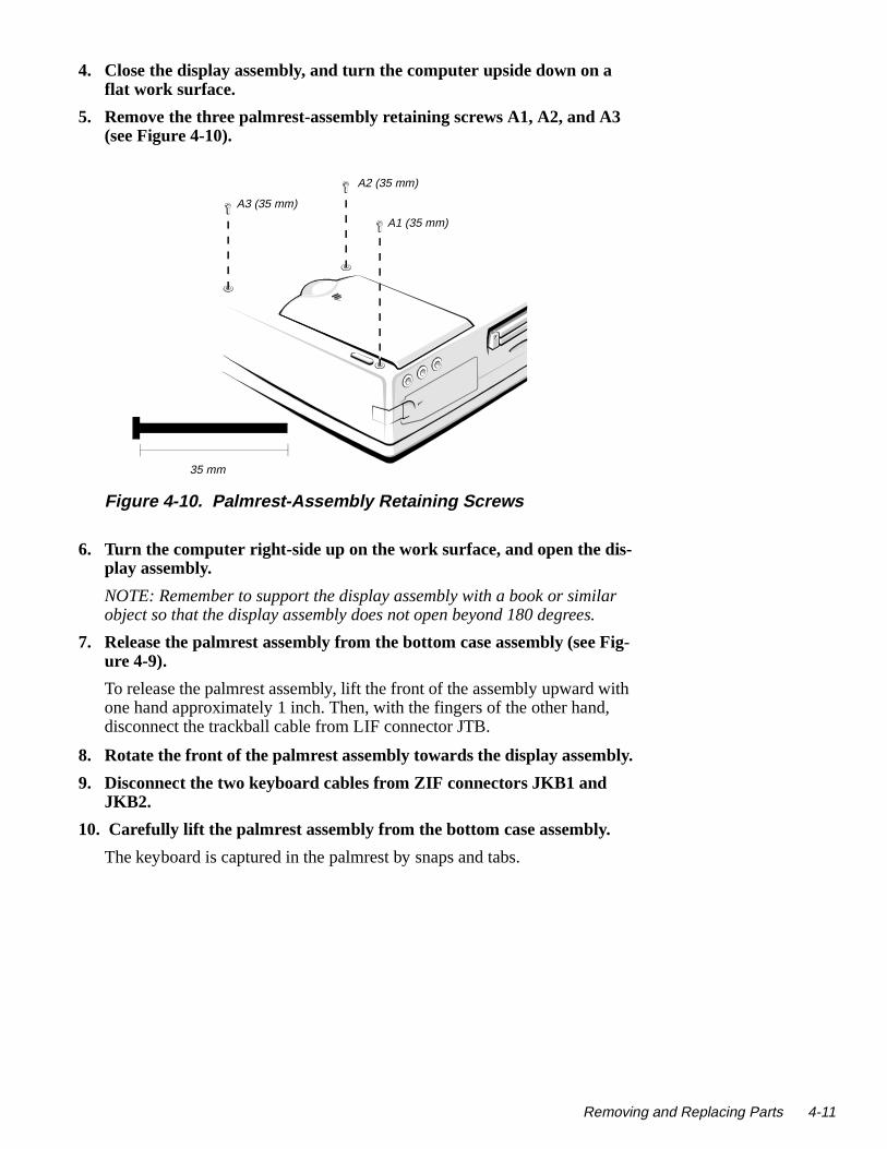
5. Remove the three palmrest-assembly retaining screws A1, A2, and A3(see Figure 4-10).
Figure 4-10. Palmrest-Assembly Retaining Screws
6. Turn the computer right-side up on the work surface, and open the dis-play assembly.
NOTE: Remember to support the display assembly with a book or simiobject so that the display assembly does not open beyond 180 degrees
7. Release the palmrest assembly from the bottom case assembly (see Fig-ure 4-9).
To release the palmrest assembly, lift the front of the assembly upward one hand approximately 1 inch. Then, with the fingers of the other hand, disconnect the trackball cable from LIF connector JTB.
8. Rotate the front of the palmrest assembly towards the display assembly
9. Disconnect the two keyboard cables from ZIF connectors JKB1 and JKB2.
10. Carefully lift the palmrest assembly from the bottom case assembly.
The keyboard is captured in the palmrest by snaps and tabs.
A1 (35 mm)
A2 (35 mm)
A3 (35 mm)
35 mm
Removing and Replacing Parts 4-11

4-12 Dell Latitude XPi CD S
mrest
ile
the Then face,
To reseat the palmrest assembly on the bottom case assembly, set the palassembly down, slightly forward of its original position, on top of the bottomcase assembly. Then push down on all sides of the palmrest assembly whsliding the assembly toward the back of the computer.
Ensure that the palmrest assembly is properly aligned and fully seated on bottom case assembly and that all of the mounting tabs are fully engaged. close the display assembly, turn the computer upside down on the work surand reinstall retaining screws A1, A2, and A3 (see Figure 4-10).
CAUTION: Be careful not to bend the CD-ROM EMI clip. Set the palm-rest assembly top side down, when the palmrest assembly is free fromthe bottom case assembly.
ervice Manual

Trackball Assembly
Figure 4-11. Trackball Assembly Removal
To remove the trackball assembly, follow these steps:
1. Remove the palmrest assembly.
2. Turn the palmrest assembly upside down on a flat work surface.
3. Remove screws A4 and A5.
4. Lift the trackball assembly out of the palmrest assembly.
NOTE: It is not necessary to remove the trackball button board when removing the trackball assembly.
Part or Assembly Name Order Name
Optical trackball assembly SVC,ASSY,TBALL/SWT,LXPi+
palmrest assembly
A4 (6 mm)
trackball assembly
A5 (6 mm)
6 mm
trackball cable
Removing and Replacing Parts 4-13

4-14 Dell Latitude XPi CD S
Keyboard Assembly
Figure 4-12. Keyboard Assembly Removal
Part or Assembly Name Order Name
Keyboard assembly, Belgium KYBD,86,BEL,ALPS,LXPi+
Keyboard assembly, China KYBD,85,CHI,ALPS,LXPi+
Keyboard assembly, domestic SVC,KYBD,85,DOM,LXPi+
Keyboard assembly, Danish KYBD,86,DEN,ALPS,LXPi+
Keyboard assembly, French KYBD,86,FR,ALPS,LXPi+
Keyboard assembly, French/Canadian
KYBD,85,FR,CAN,ALPS,LXPi+
Keyboard assembly, German KYBD,86,GER,ALPS,LXPi+
Keyboard assembly, Japan KYBD,87,JPN,LXPi+
Keyboard assembly, Korean KYBD,85,KOREA,ALPS,LXPi+
Keyboard assembly, Latin AmericanKYBD,86,LTN,ALPS,LXPi+
Keyboard assembly, Norwegian KYBD,86,NOR,ALPS,LXPi+
Keyboard assembly, Russian KYBD,86,RUS,ALPS,LXPi+
Keyboard assembly, Spanish KYBD,86,SPN,ALPS,LXPi+
Keyboard assembly, Swedish KYBD,86,SWE,ALPS,LXPi+
trackball assembly
press
press
keyboard
palmrest assembly
ervice Manual

To remove the keyboard assembly, follow these steps:
1. Remove the palmrest assembly.
2. Press along the sides of the keyboard to release the keyboard from thepalmrest assembly.
Part or Assembly Name Order Name
Keyboard assembly, Swiss KYBD,86,SWI,ALPS,LXPi+
Keyboard assembly, Thailand KYBD,85,THAI,ALPS,LXPi+
Keyboard assembly, United Kingdom
KYBD,84,UK,LXPi+
Removing and Replacing Parts 4-15

4-16 Dell Latitude XPi CD S
Display AssemblyFor removal procedures, the display assembly consists of the following:
• Tilt-support foot
• Display assembly bezel
• Display assembly latch and latch spring
• LCD panel
• LCD inverter board
• Hinge covers
• Display-assembly interface cable
• Microphone/switch assembly
Tilt-Support Foot
Figure 4-13. Tilt-Support Foot Removal
Part or Assembly Name Order Name
Tilt-support foot, left FOOT,PLSTC,REAR,LF,LXPiCD
Tilt-support foot, right FOOT,PLSTC,REAR,RT,LXPiCD
right tilt-support foot
10 mm
finger-access recess
foot retaining screw (10 mm)cover
tab
notch
ervice Manual

the
ay
tall . and ntil
To remove a tilt-support foot, follow these steps:
1. Close the display assembly.
2. With the foot set to its fully retracted position, insert a small device (such as a scribe) into the bottom notch on the foot-retaining screw cover and gently lift out the cover partway. Lift on the sides of the cover, working around to the top, and then lift out the cover.
3. Remove the foot retaining screw.
The foot retaining screw also functions as a mounting screw for one of display assembly hinges, which has a threaded hole for the screw. Therefore, the foot retaining screws cannot be reinstalled with the displassembly removed.
The foot-retaining screw cover can fit only one way in the foot. To reinsthe cover, make sure the tilt-support foot is in its fully retracted positionThen orient the cover with the notch toward the bottom of the computerits mounting tab toward the top of the computer. Press in on the cover uit snaps into place.
Removing and Replacing Parts 4-17

4-18 Dell Latitude XPi CD S
Display Assembly
Figure 4-14. Display Assembly Removal
To remove the display assembly, follow these steps:
1. Remove the palmrest assembly.
2. Remove the computer’s tilt-support feet.
3. Remove interface-cable grounding screws C1 and C2 from the display assembly.
Part or Assembly Name Order Name
Display assembly ASSY,LCD,TFT,SVGA,12.1”,LXPiCD
C1 (6 mm)
connector JLCD connector JMIC
6 mm
left tilt-support foot
right tilt-support foot
detent post
display assembly
C2 (6 mm)
ervice Manual

e
the
4. Disconnect the display-assembly interface cable from connector JLCDon the system board.
To disconnect the cable, grasp the pull tab and pull it straight up from thsystem board.
5. Disconnect the microphone cable from ZIF connector JMIC.
6. Lift the display assembly from the bottom case assembly.
A plastic detent post located approximately at the center of the display assembly may hang on the bottom case assembly. If so, carefully pushcenter of the display assembly away from the bottom case assembly.
Removing and Replacing Parts 4-19
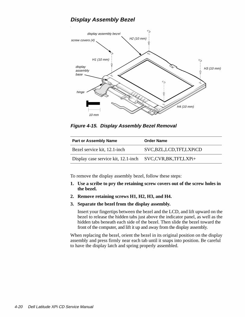
4-20 Dell Latitude XPi CD S
the as the d the
play eful
Display Assembly Bezell
Figure 4-15. Display Assembly Bezel Removal
To remove the display assembly bezel, follow these steps:
1. Use a scribe to pry the retaining screw covers out of the screw holes inthe bezel.
2. Remove retaining screws H1, H2, H3, and H4.
3. Separate the bezel from the display assembly.
Insert your fingertips between the bezel and the LCD, and lift upward onbezel to release the hidden tabs just above the indicator panel, as well hidden tabs beneath each side of the bezel. Then slide the bezel towarfront of the computer, and lift it up and away from the display assembly.
When replacing the bezel, orient the bezel in its original position on the disassembly and press firmly near each tab until it snaps into position. Be carto have the display latch and spring properly assembled.
Part or Assembly Name Order Name
Bezel service kit, 12.1-inch SVC,BZL,LCD,TFT,LXPiCD
Display case service kit, 12.1-inchSVC,CVR,BK,TFT,LXPi+
screw covers (4)
H1 (10 mm)
H2 (10 mm)
H3 (10 mm)
H4 (10 mm)
10 mm
display assembly bezel
display assembly base
hinge
ervice Manual

Display Assembly Latch and Latch Spring
Figure 4-16. Display Assembly Latch and Latch Spring Removal
To remove the display assembly latch and latch spring, follow these steps:
1. Remove the display assembly bezel.
2. Turn the display assembly bezel upside down on the work surface.
3. While holding down the display-assembly latch spring, slide the latch against the spring, rotate the latch upward, and lift the latch and spring out of the bezel.
Part or Assembly Name Order Name
Display assembly latch LTCH,LXPiCD
Display assembly latch spring SPR,LTCH,LXPiCD
latch
latch spring
display assembly bezel
Removing and Replacing Parts 4-21

4-22 Dell Latitude XPi CD S
LCD Panel
Figure 4-17. LCD Panel Removal
Part or Assembly Name Order Name
LCD panel LCD,TFT,SVGA,12.1”,SAMSUNG
LCD assembly, LCD inverter board, active-matrix color, TFT SVGA display
SVC,LCD/INVTR,TFT,LXPiCD
LCD panel
LCD power cable
connector CN2LCD inverter board
display assembly case
interface connector
interface cable
ervice Manual

To remove the LCD panel, follow these steps:
1. Remove the display assembly bezel.
2. Lift the lower edge of the LCD panel about 1 inch.
3. Disconnect the LCD-assembly power cable from connector CN2 on theLCD inverter board.
4. Lift the lower edge of the LCD panel approximately 3 inches.
5. Disconnect the display-assembly interface cable from the LCD interfaceconnector on the underside of the LCD panel.
6. Lift the LCD panel out of the display assembly case.
Removing and Replacing Parts 4-23

4-24 Dell Latitude XPi CD S
LCD Inverter Board
Figure 4-18. LCD Inverter Board Removal
To remove the LCD inverter board, follow these steps:
1. Remove the display assembly bezel.
2. Remove screws I1 and I2 securing the display-interface cable retainingbracket, and then remove the bracket.
3. Move the LED board out of the display assembly case far enough to gain access to the LCD inverter board.
4. Disconnect the LCD-inverter board interface cable from ZIF connector CN1 on the LCD inverter board.
5. Lift the LCD inverter board about 1/4 of an inch.
6. Disconnect the LCD power cable from connector CN2 on the LCD inverter board.
7. Lift the LCD inverter board out of the display assembly case.
Part or Assembly Name Order Name
LCD inverter board ASSY,BD,INVRTR,TFT,SVGA12.1”
retaining bracket
I1 (5 mm)
I2 (5 mm)5 mm
LED board
inverter board
display assembly case
connector CN1
connector CN2
ervice Manual

the
e
hat e the
Hinge Covers
Figure 4-19. Hinge Covers Removal
Each of the hinge covers is held in place by three tabs that fit into slots on display assembly base. The microphone is inside the right hinge cover. Toremove the hinge covers, follow these steps:
1. Remove the display assembly from the computer.
2. Place the display assembly faceup on the work surface.
3. Rotate the display assembly base until the display assembly hinges arepointing upward at approximately a 45-degree angle.
4. To remove a hinge cover, press in on the front of the cover to release thhinge cover’s front tab. Then rotate the cover in the direction of the arrow, and lift the cover away from the display assembly base.
To replace the hinge covers, set the display assembly base in the position shown, and reinsert the hinge cover into its original position, making sure tits two tab slots engage the tabs on the display assembly base. Then rotathinge cover opposite to the direction shown in Figure 4-18 until its front tabengages the tab slot in the display assembly base.
display assembly base
hinge
hinge cover
Removing and Replacing Parts 4-25

4-26 Dell Latitude XPi CD S
el,
Display-Assembly Interface Cable
Figure 4-20. Display-Assembly Interface Cable Removal
The display-assembly interface cable connects the system board, LCD panLCD inverter board, and LED board. The cable wraps around a bobbin. Toremove the display-assembly interface cable, follow these steps:
1. Remove the display assembly.
2. Remove the display assembly bezel.
3. Remove the LCD panel.
4. Remove the left hinge cover.
5. Remove screws I1 and I2 securing the display-interface cable retainingbracket, then remove the bracket.
6. Disconnect the display-assembly interface cable from ZIF connector CN1 on the LCD inverter board.
Part or Assembly Name Order Name
LCD cables, active-matrix, TFT SVGA display (includes display-assembly interface, LED board, and LCD-inverter-board interface cables)
SVC,CBL,LCD,TFT,SAMSUNG,LXPiCD
I1 (5 mm)
I2 (5 mm)
connector CN1bobbin5 mm
alignment markson cable
retaining bracket
alignment notch in shoulder
LED board
display-assembly interface cable
ervice Manual

ches top
sive h in king bin
7. Lift the display-assembly interface cable and bobbin out of the display assembly.
NOTE: Some computers have a display-assembly interface cable that detafrom the bobbin. If you have a cable with a permanently attached bobbin, shere; otherwise, proceed to Step 8.
8. Look at the alignment marks on the display-assembly interface cable, and note the alignment of the cable to the bobbin. Then carefully detachthe cable from the bobbin.
A double-sided adhesive strip attaches the cable to the bobbin (see Figure 4-20).
9. To reattach the display-assembly interface cable to the bobbin, align themarks on the cable with the notch in the shoulder of the bobbin, and then wrap the cable around the bobbin.
If you are installing a new cable, remove the protective cover from the adhestrip on the new cable. Align the alignment marks on the cable with the notcthe shoulder of the bobbin, and then wrap the cable around the bobbin, masure it stays between the shoulders of the bobbin. Place the cable and bobinto the display assembly before attaching the EMI shield.
Removing and Replacing Parts 4-27

4-28 Dell Latitude XPi CD S
ly. To
Microphone/Switch Assembly
Figure 4-21. Microphone/Switch Assembly Removal
The microphone/switch assembly is inside the right hinge cover. There is amicrophone and a magnetic reed switch on the microphone/switch assembremove the microphone/switch assembly, follow these steps:
1. Remove the display assembly.
2. Remove the right hinge cover. (Before doing so, note the correct routingof the microphone cable around the display assembly base.)
3. Remove the microphone cover from the right hinge cover.
4. Open the microphone cover, and remove the microphone/switch assembly.
Part or Assembly Name Order Name
Microphone service kit SVC,MIPHN/SWT,LXPiCD
microphone/switch assembly
right hinge cover
microphone cover
microphone/switch cable
magnet switch
ervice Manual

Bottom Case AssemblyThe bottom case assembly consists of the following:
• Diskette/CD-ROM assembly
• Deck-buoy
• Superpart assembly
• System board
• 3.1-V power supply board
• I/O-panel dust cover
• Dust cover for the Advanced Port Replicator
• Audio board
Removing and Replacing Parts 4-29

4-30 Dell Latitude XPi CD S
Figure 4-22. Bottom Case Assembly Removal
Part or Assembly Name Order Name
Bottom case assembly ASSY,CVR,BTM,LXPiCD
bottom case assembly
system board assembly
memory compartment cover
I/O bracket clip
I/O bracket clip
superpart assembly
3.1-V power supply
spreader plate
diskette/CD-ROM assembly
audio board
keel plate
I/O panel dust cover
dust cover for the Advanced Port Replicator
superpart serial EMI clip
superpart docking EMI clip
ervice Manual
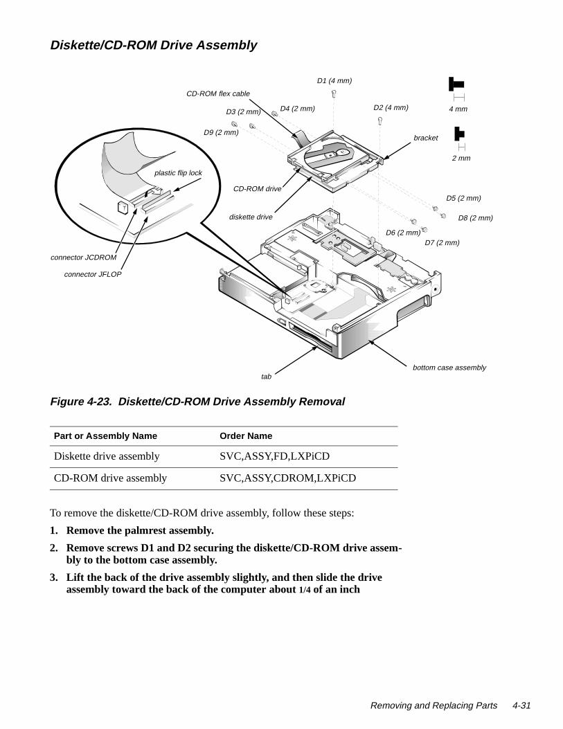
-
4 mm
D5 (2 mm)
m)
2 mm
bracket
bottom case assembly
D7 (2 mm)
D8 (2 mm)
Diskette/CD-ROM Drive Assembly
Figure 4-23. Diskette/CD-ROM Drive Assembly Removal
To remove the diskette/CD-ROM drive assembly, follow these steps:
1. Remove the palmrest assembly.
2. Remove screws D1 and D2 securing the diskette/CD-ROM drive assembly to the bottom case assembly.
3. Lift the back of the drive assembly slightly, and then slide the drive assembly toward the back of the computer about 1/4 of an inch
Part or Assembly Name Order Name
Diskette drive assembly SVC,ASSY,FD,LXPiCD
CD-ROM drive assembly SVC,ASSY,CDROM,LXPiCD
diskette drive
CD-ROM drive
connector JCDROM
connector JFLOP
D1 (4 mm)
D2 (4 mm)D3 (2 mm) D4 (2 mm)
D6 (2 m
CD-ROM flex cable
tab
D9 (2 mm)
plastic flip lock
Removing and Replacing Parts 4-31

4-32 Dell Latitude XPi CD S
ore
bles ssem-
the
4. Lift the drive assembly straight up about 1 inch.
The front edge of the drive assembly engages tabs on the bottom caseassembly. Make sure the diskette drive assembly is clear of the tab befattempting to lift it out of the bottom case assembly.
5. Disconnect the diskette drive and CD-ROM drive interface cables from connectors JFLOP and JCDROM on the system board.
6. Lift the drive assembly out of the bottom case assembly.
When replacing the drive assembly, first connect the two drive interface cato the system board. Then lower the drive assembly into the bottom case ably, beginning with its forward edge, so that the diskette drive board fits between the tabs in the corner of the bottom case assembly.
To separate the diskette/CD-ROM assembly into a diskette drive and a CD-ROM drive, remove screws D3 through D9. Lift up the CD-ROM, and remove it from the assembly. Slide the CD-ROM flex cable out of the slot inbracket that holds the CD-ROM to the diskette drive.
CAUTION: Before removing the diskette drive and CD-ROM driveinterface cables from connectors JFLOP and JCDROM, release eachconnector’s plastic flip lock (see Figure 4-23). Do not pull the interfacecable from the connector; doing so can ruin the cable’s electricalconductivity.
CAUTION: Use care when handling the diskette/CD-ROM drive; it isfragile and will bend if handled improperly. Place the assembly on a flatwork surface, and carefully remove the small 2-mm screws. Do not bendeither the drives or the bracket. If bending occurs, the diskette or CD-ROM will not function correctly when inserted in the drive.
ervice Manual

Deck Buoy
Figure 4-24. Deck Buoy Removal
To remove the deck buoy, follow these steps:
1. Remove the palmrest assembly.
2. Remove the display assembly.
3. Remove the diskette/CD-ROM assembly.
4. Remove screws B1, B2, and B3.
Lift the deck buoy out of the bottom case assembly.
Part or Assembly Name Order Name
Deck buoy ASSY,CLMP,THRM,LXPiCD
B1 (10 mm)
B2 (10 mm)
B3 (10 mm)
bottom case assembly
10 mm
deck buoy
Removing and Replacing Parts 4-33

4-34 Dell Latitude XPi CD S
ry, a o
Superpart Assembly
Figure 4-25. Superpart Assembly Removal
The superpart assembly includes two speakers, two fans, the reserve batteprinted circuit board for those parts, and an infrared printed circuit board. Tremove the superpart assembly, follow these steps:
1. Remove the palmrest assembly.
2. Remove the display assembly.
3. Remove the diskette-drive/CD-ROM assembly.
4. Remove the deck-buoy.
Part or Assembly Name Order Name
Superpart assembly SVC,ASSY,FAN/SPKR,BRKT,LXPiCD
bottom case assembly
B4 (25 mm)
25 mm
superpart assembly
thermal tape
ervice Manual

5. Remove screw B4.
Lift the superpart assembly out of the bottom case assembly.
CAUTION: To prevent tearing the thermal tape, slowly pull the super-part assembly away from the system board.
Removing and Replacing Parts 4-35

4-36 Dell Latitude XPi CD S
-
Reserve Battery
Figure 4-26. Reserve Battery Removal
Part or Assembly Name Order Name
Reserve battery SVC,BTRY,RSRV,LXP
CAUTION: The reserve battery provides power to the computer’s RTCand NVRAM when the computer is turned off. Removing the batterycauses the computer to lose its date and time information as well as usersettable parameters in the NVRAM. If possible, make a copy of thisinformation before you remove the reserve battery.
reserve battery
connector JRBAT
F1 (3 mm)
F2 (3 mm)
F3 (3 mm)
F4 (3 mm)
speaker/fan bracket
superpart
middle tab
3 mm
speaker (2)
speaker (2)
superpart serial EMI clip
superpart docking EMI clip
ervice Manual

ugh
To remove the reserve battery, follow these steps:
1. Remove the palmrest assembly.
2. Remove the superpart assembly.
3. Remove the superpart docking EMI clip and the superpart serial EMI clip.
4. Unplug the battery from connector JRBAT.
5. Place the superpart assembly upside down on a flat work surface.
6. Remove screws F1 through F4.
Remove the speaker/fan bracket protecting the speakers and fan.
7. Lift the battery out of its recess in the superpart assembly.
To free the reserve battery, thread the battery cable and connector throthe opening in the plastic superpart assembly.
CAUTION: When replacing the speaker/fan bracket, be sure to rein-stall the middle tab correctly.
Removing and Replacing Parts 4-37

4-38 Dell Latitude XPi CD S
ich is ment for mbly.
System Board Assembly
Figure 4-27. System Board Assembly Removal
The system board’s BIOS chip contains the system service tag number, whalso visible on a bar-code label on the bottom of the computer. The replacekit for the system board assembly includes a diskette that provides a utilitytransferring the service tag number to the replacement system board asse
Part or Assembly Name Order Name
System board assembly SVC,SYS,PLN,LXPiCD-150ST,WB,0M
CAUTION: Dell uses the system’s service tag number to maintain a his-tory of the computer and its maintenance services. Do not neglect totransfer the service tag number to the replacement system board assem-bly (see step 3 of “Replacing the System Board Assembly” found later inthis section).
system board assembly
bottom case assembly
SB1 (5 mm)
SB2 (5 mm)
5 mm
main battery connector
battery compartment
PC Card ejectors
molded tabs (3)
I/O docking EMI clip
I/O serial EMI clip
ervice Manual

m
ase
sem-
Removing the System Board Assembly
To remove the system board assembly, follow these steps:
1. Remove the palmrest assembly.
2. Remove the display assembly.
3. Remove the diskette/CD-ROM assembly.
4. Verify that the PC Card ejectors are fully depressed.
5. Remove the deck buoy plate. (Reinstall this part on the new system board.)
6. Remove the superpart assembly.
Carefully disengage the superpart docking EMI and serial EMI clips frothe I/O docking EMI and serial EMI clips.
7. Remove screws SB1 and SB2, which retain the system board (see Figure 4-27).
8. Lift the system board approximately 2 inches from the back of the computer.
9. Disengage the front of the system board from the three molded tabs in the bottom case assembly.
The tabs’ approximate location is shown in Figure 4-27. The tabs are located alongside the hard-disk drive compartment, inside the bottom cassembly.
10. Lift the system board assembly out of the bottom case assembly.
NOTE: If the main battery insulator comes out with the system board asbly, detach the insulator and set it aside.
CAUTION: To ensure maximum cooling for the microprocessor, donot touch the heat transfer area on the system board above the micro-processor or on the deck buoy plate. The oils in your skin reduce theheat transfer of the thermal pads.
CAUTION: When removing the system board assembly, be carefulnot to damage the main battery connector and EMI shield on the bot-tom of the assembly.
Removing and Replacing Parts 4-39

4-40 Dell Latitude XPi CD S
rly.
t
embly on
Replacing the System Board Assembly
Observe the following precautions when you reinstall a system board:
1. Before reinstalling the system board assembly, make sure the upper I/Obracket clip and the side I/O bracket clip are in place. If the side I/O bracket clip has been dislodged, reinstall it as shown in Figure 4-27.
Figure 4-28. I/O Bracket Clips
2. While reinstalling the system board assembly, make sure the power button is positioned as far as it will go toward the back of the computer.
This will ensure that the power button engages the power switch prope
3. Enter the system’s service tag number into the BIOS of the replacemensystem board assembly.
Insert the diskette that accompanied the replacement system board assinto the diskette drive, and turn on the computer. Follow the instructionsthe display screen.
CAUTION: To avoid possible damage to the computer, make sure thesystem board assembly is inserted under the three molded tabs at thefront of the bottom case assembly.
I/O bracket clip
ervice Manual

ctors
3.1-V Power Supply Board
Figure 4-29. 3.1-V Power Supply Board Removal
To remove the 3.1-V power supply board, follow these steps:
1. Remove the palmrest assembly
2. Remove the superpart assembly.
3. Remove the 3.1-V power supply board from the system board.
The power supply board is held in place on the system board by conneJPS1 and JPS2.
Part or Assembly Name Order Name
3.1-V power supply board CRD,PWR SPLY,LXPiCD,V3.1,NBK
connector JPS1
connector JPS2
bottom case assembly
system board
power supply boardwith insulator
Removing and Replacing Parts 4-41

4-42 Dell Latitude XPi CD S
its e rom
and dust
I/O-Panel Dust Cover
Figure 4-30. I/O-Panel Dust Cover Removal
To remove the I/O-panel dust cover, follow these steps:
1. Remove the palmrest assembly.
2. Remove the display assembly.
3. Remove the superpart assembly.
4. Remove the system board.
5. Remove the I/O-panel dust cover.
Push outward on one end of the dust cover to release the pivot pin fromassociated pivot hole. Then repeat the operation for the other end of thcover. After both ends have been disengaged, lift the dust cover away fthe system board assembly.
To replace the I/O-panel dust cover, orient the cover in its original position snap the pivot pins into place in their associated pivot holes. Make sure thecover opens and closes freely before you reinstall the display assembly.
Part or Assembly Name Order Name
I/O-panel dust cover DOOR,PLSTC,I/O,LXP/NBK
I/O-panel dust cover
pivot pin (2)
pivot hole (2)
ervice Manual

w
Advanced Port Replicator Connector Dust Cover
Figure 4-31. Advanced Port Replicator Connector Dust Cover
To remove the dust cover for the Advanced Port Replicator connector, follothese steps:
1. Remove the palmrest assembly.
2. Remove the display assembly.
3. Remove the dust cover.
Part or Assembly Name Order Name
Advanced Port Replicator connector dust cover
CVR,DOOR,DOCKING,LXP
Advanced Port Replicator connec-tor dust cover
Removing and Replacing Parts 4-43
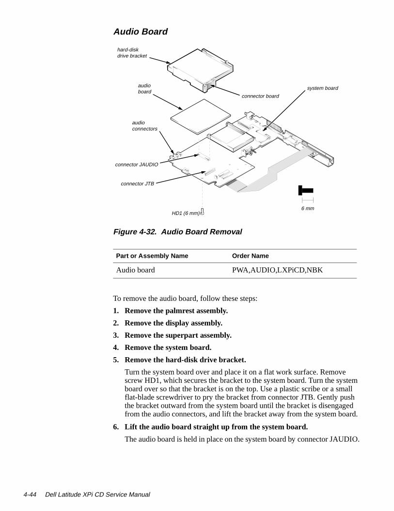
4-44 Dell Latitude XPi CD S
stem all
sh ed ard.
DIO.
Audio Board
Figure 4-32. Audio Board Removal
To remove the audio board, follow these steps:
1. Remove the palmrest assembly.
2. Remove the display assembly.
3. Remove the superpart assembly.
4. Remove the system board.
5. Remove the hard-disk drive bracket.
Turn the system board over and place it on a flat work surface. Removescrew HD1, which secures the bracket to the system board. Turn the syboard over so that the bracket is on the top. Use a plastic scribe or a smflat-blade screwdriver to pry the bracket from connector JTB. Gently puthe bracket outward from the system board until the bracket is disengagfrom the audio connectors, and lift the bracket away from the system bo
6. Lift the audio board straight up from the system board.
The audio board is held in place on the system board by connector JAU
Part or Assembly Name Order Name
Audio board PWA,AUDIO,LXPiCD,NBK
6 mm
connector JTB
audio board
audio connectors
system board
hard-disk drive bracket
HD1 (6 mm)
connector JAUDIO
connector board
ervice Manual

Appendix AFactory Repair Parts
m- field. hap-
he
ea-ing
-ing
This appendix provides procedures for removing and replacing factory coponents and subassemblies at a service facility. (Dell does not recommendremoval and replacement of factory components and subassemblies in theFor removal and replacement procedures for field-replaceable parts, see Cter 4, “Removing and Replacing Parts.”)
Recommended ToolsMost of the procedures in this appendix require the use of one or more of tfollowing tools:
• Small flat-blade screwdriver
• Jeweler’s screwdriver set
• Number 1 magnetized Phillips-head screwdriver
• Number 2 magnetized Phillips-head screwdriver
• Chip-removal tool
• Wrist grounding strap
• Small plastic scribe
• Nut drivers
Precautionary MeasuresBefore you begin working on the computer, read about the precautionary msures, screw identification, and computer orientation outlined at the beginnof Chapter 4, “Removing and Replacing Parts.”
Factory Repair Parts and AssembliesTable A-1 lists the factory repair parts and assemblies available for the computer. The subsections that follow Table A-1 provide instructions for removand replacing these parts and assemblies.
Factory Repair Parts A-1

A-2 Dell Latitude XPi CD S
Table A-1. Factory Repair Parts and Assemblies
Part or Assembly Name Order Name Figure
AC Adapter and Power Cords
AC adapter ADPT,AC,EXT,18V,65W,LXP
Power cable, U.S. CORD,PWR,110V,6F,ACADPT,US
Power cable, Europe CORD,PWR,220V,6F,AC ADPT,EUR
Power cable, Australia CORD,PWR,220V,6F,AC ADPT,AUS
Power cable, U.K. CORD,PWR,220V,6F,AC ADPT,UK
Audio
Audio board service kit SVC,ASSY,AUD BD/SPKR,LXPi+
4-32
Microphone service kit SVC,ASSY,MIPHN,LXPi+CD 4-21
Microphone/switch assembly
ASSY,MIPHN/SWT,LXPi+CD 4-21
Magnet switch SWT,MGNT,ENCL,SPST,LXPiCD
4-21
Microphone/switch cable
CBL,FPC,MIC/SW,LCD,12.1" 4-21
Technical booklet DOC,SERV,GDE,XPi+
Batteries
Reserve battery SVC,BTRY,RSRV,LXP 4-26
Battery, reserve BTRY,RSV,LXP
Technical booklet TSH,SERV,LXP
ervice Manual

Batteries (Continued)
Main battery assembly CUS,BTRY,SAR,36WHR,LXP 4-2
Main battery BTRY,MAIN,36WH,LXP/XPi
Technical booklet TSH,BTRY,LXP
CD-ROM Drive Assembly
CD-ROM drive assembly SVC,ASSY,CD,LXPiCD 4-23
CD-ROM bezel BZL,CD,PLSTC,LXPiCD
CD-ROM bezel assembly
SUBASSY,BZLPLSTC,CD,LXPiCD
CD-ROM bezel spring
SPR,FL,CLP,CD BZL,LXPiCD
CD-ROM drive CD,627M,I,INT,CC,LXPiCD
CD-ROM drive cable
CBL,FPC,CD,LXPiCD
Eject button BTN,EJCT,CD,LXPiCD
Screws, diskette/CD-ROM drive bracket
SCR,M2X2MM,PHH,MS,ZPS,NBK
Diskette Drive Assembly
Diskette drive assembly SVC,ASSY,FD,LXPiCD 4-23
Diskette drive FD,1.44M,F3,LXPiCD
Diskette drive cable CBL,FPC,FD,LXPiCD
Eject button BTN,EJCT,FD,LXPiCD
Technical booklet DOC,SERV,GDE,XPi+
Screws, diskette/CD-ROM drive bracket
SCR,M2X2MM,PHH,MS,ZPS,NBK
Table A-1. Factory Repair Parts and Assemblies (Continued)
Part or Assembly Name Order Name Figure
Factory Repair Parts A-3

A-4 Dell Latitude XPi CD S
Diskette Drive Assembly (Continued)
Diskette/CD-ROM drive assembly
SUBASSY,FD/CD,LXPiCD 4-23
Diskette/CD-ROM bracket BRKT,FD,AL,RT,LXPiCD 4-23
Hard-Disk Drive Assemblies
Hard-disk drive assembly CUS,HD, xxxxx,yy,MM,zzz,LXP*
4-6
Hard-disk drive, subassembly
SUBASSY,HD,xxxxx,yy,MM,zzz,LXP*
Hard-disk drive
HD,xxxxx,yy,MM,zzz,REV2*
Hard-disk drive bracket
BRKT,HD,LXP
Hard-disk drive mount-ing screws
SCR,M3X4,BIND/PHH,BL OXIDE
Hard-disk drive insulator
INSUL,yyMM,LXP*
Technical booklet TSH,HD,LXP
Keyboards
Keyboard assembly, Belgium
KYBD,86,BEL,ALPS,LXPi+ 4-5
Keyboard assembly, China KYBD,85,CHINA,ALPS,LXPi+
4-5
Keyboard assembly, domestic
SVC,KYBD,85,DOM,LXPi+ 4-5
Keyboard assembly, Danish KYBD,86,DEN,ALPS,LXPi+ 4-5
Keyboard assembly, French KYBD,86,FR,ALPS,LXPi+ 4-5
* Substitute your drive capacity for xxxxx, your drive height for yy, and themanufacturer for zzz.
Table A-1. Factory Repair Parts and Assemblies (Continued)
Part or Assembly Name Order Name Figure
ervice Manual

Keyboards (Continued)
Keyboard assembly, French/Canadian
KYBD,85,FR,CAN,ALPS,LXPi+ 4-5
Keyboard assembly, German
KYBD,86,GER,ALPS,LXPi+ 4-5
Keyboard assembly, Japan KYBD,87,JPN,LXPi+ 4-5
Keyboard assembly, Korean KYBD,85,KOREA,ALPS,LXPi+ 4-5
Keyboard assembly, Latin KYBD,86,LTN,ALPS,LXPi+ 4-5
Keyboard assembly, Norwegian
KYBD,86,NOR,ALPS,LXPi+ 4-5
Keyboard assembly, Russian
KYBD,86,RUS,ALPS,LXPi+ 4-5
Keyboard assembly, Spanish
KYBD,86,SPN,ALPS,LXPi+ 4-5
Keyboard assembly, Swedish
KYBD,86,SWE,ALPS,LXPi+ 4-5
Keyboard assembly, Swiss KYBD,86,SWI,ALPS,LXPi+ 4-5
Keyboard assembly, Thailand
KYBD,85,THAI,ALPS,LXPi+ 4-5
Keyboard assembly, U.K. KYBD,84,UK,LXPi+ 4-5
LCD Assemblies
LCD panel, LCD inverter board, active-matrix color, TFT SVGA display
SVC,LCD/INVTR,TFT,LXPi+CD
LCD panel LCD,TFT,SVGA,12.1”,SAMSUNG
4-17
LCD inverter board ASSY,BD,INVTR,TFT,SVGA,12.1”
4-17
Technical booklet DOC,SERV,GDE,XPi+
Table A-1. Factory Repair Parts and Assemblies (Continued)
Part or Assembly Name Order Name Figure
Factory Repair Parts A-5

A-6 Dell Latitude XPi CD S
LCD Assemblies (Continued)
LCD/LED/inverter board cable, service kit, active-matrix color, TFT SVGA display
SVC,CBLS,LCD,TFT,SAM-SUNG,LXPi+CD
Display-assembly interface cable
CBL,FPC,LED/INVRTR,TFT,12.1”
4-20
Display-assembly interface cable bob-bin, 12.1-inch
BBN,LCD,TFT,12.1” 4-20
Technical booklet DOC,SERV,GDE,XPi
Bezel service kit, 12.1-inch SVC,BZL,LCD,TFT,LXPiCD 4-15
Display assembly bezel 12.1-inch
ASSY,LCD,BZL,12.1” 4-15
Display-assembly latch spring
SPR,LTCH 4-16
Technical booklet DOC,SERV,GUIDE,LXPi
Display case service kit, 12.1-inch
SVC,CVR,BK,TFT,LXPi+
Display assembly case, 12.1-inch
ASSY,LCD,CVR,BK,TFT,12.1” 4-17
Technical booklet DOC,SERV,GUIDE,LXPi
Display assembly latch ser-vice kit, 12.1-inch
SVC,LTCH,DIS,TFT,LXPi+
Display assembly latch, 12.1-inch
LTCH,LCD,STN/TFT,LXP 4-16
Display-assembly latch spring, 12.1-inch
SPR,LTCH 4-16
Technical booklet DOC,SERV,GUIDE,LXPi
Table A-1. Factory Repair Parts and Assemblies (Continued)
Part or Assembly Name Order Name Figure
ervice Manual

LCD Parts
Hinge cover, right CVR,HNG,RT,MIPHN,LXPi+ 4-21
Hinge cover, left CVR,HNG,LXP
Display assembly base ASSY,CVR,BTM,DIS,LXPiCD 4-19
Left hinge HNG,LCD,LFT,TFT,12.1" 4-15
Right hinge HNG,LCD,RT,TFT,12.1" 4-19
Display-assembly-bezel re-taining screw covers, lower
CVR,LCD,LWR,LXPiCD 4-15
Display-assembly-bezel re-taining screw covers, upper
BMPR,UPR,LCD,LXPiCD 4-15
Display-assembly EMI shield 12.1-inch
SHLD,LCD,MET,TFT,12.1” A-4
Memory
Memory module, 4-MB, customer kit
CUS,MEM,4M,LXP4D/T,LXPi
4-9
Memory module, 4-MB
SIMM,4MB,LXP
Technical booklet TSH,DIMM INSTL,LXP
Memory module, 8-MB, customer kit
CUS,MEM,8M,LXP4D/T,LXPi
4-9
Memory module, 8-MB
DIMM,8M,2X32,TL,LXP
Technical booklet TSH,DIMM INSTL,LXP
Memory module, 16-MB, customer kit
CUS,MEM,16M,LXP4D/T,LXPi
4-9
Memory module, 16-MB
SIMM,16MB,LXP
Technical booklet TSH,DIMM INSTL,LXP
Table A-1. Factory Repair Parts and Assemblies (Continued)
Part or Assembly Name Order Name Figure
Factory Repair Parts A-7

A-8 Dell Latitude XPi CD S
Miscellaneous Parts
CD-ROM EMI clip CLP,EMI,CD,LXPiCD 4-5
Keyboard EMI clip CLP,EMI,KYBD,LXPiCD 4-5
Superpart serial EMI clip CLP,EMI,SER,SUPERPRT,I/O,LXPiCD
4-5
Superpart docking EMI clip CLP,EMI,DOCK,SUPERPRT,I/O,LXPiCD
4-5
Memory compartment cover
CVR,MEM,LXPiCD 4-7
PCMCIA blank INSR,BLNK,PCMCIA,LXP 4-5
PCMCIA blank, type III INSR,BLNK,PCMCIA,TYP 3,LXPiCD
4-5
Tilt-support-foot retaining screw cover
CVR,REAR,FOOT,LXP 4-12
Advanced Port Replicator connector dust cover
CVR,DOOR,DOCKING,LXP 4-31
Tilt-support foot, left FOOT,PLSTC,REAR,LF,LXPiCD
4-5
Tilt-support foot, right FOOT,REAR,RT,LXP 4-5
I/O panel dust cover DOOR,PLSTC,I/O,LXP/NBK 4-30
Main battery insulator CVR,MYLAR,BTRY,CVTY,LXPiCD
A-10
I/O bracket, hinge GSKT,I/O BRKT,BTM,EMI,LXPi
Superpart assembly SVC,ASSY,FAN/SPKR,BRKT,LXPiCD
4-33
Spreader plate PLT,SPRDR,BTM,LXPiCD A-12
Spreader plate spacer SPCR,TOP SPRDR,PORON,LXPiCD
A-12
Table A-1. Factory Repair Parts and Assemblies (Continued)
Part or Assembly Name Order Name Figure
ervice Manual

Miscellaneous Parts (Continued)
Keel plate ASSY,PLT,KEEL,LXPiCD A-12
Deck buoy ASSY,CLMP,THRM,LXPiCD 4-24
Microphone insulator bracket
INSUL,PLSTC,MIPHN/SWT,LXPiCD
Bottom case assembly CVR,BTM,BLK,LXPi 4-22
Power button BTN,PWR SWT,LXP A-11
Power-button mounting bracket
GDE,PWR SWT,PLSTC,LXPi A-11
Memory compartment cover
CVR,MEM,LXPi+CD 4-5
Palmrest Assembly
Palmrest service kit SVC,ASSY,PLMRST,LXPi+CD
Palmrest assembly SUBASSY,PLMRST,LXPi+CD 4-9
Technical booklet DOC,SERV,GUIDE,LXPiCD
Screws
Screws service kit SVC,SCR,LXP
3 mm, black SCR,2mmX3mm,PHH,MS,BLO,LXP B2
3 mm, gold SCR,2mmX3mm,PHH,MS,NON,LXP B8
4 mm, black SCR,2.6mmX4mm,PHH,MS,BLO,LXPB7
5 mm, black SCR,2.6mmX5mm,PHH,MS,BLO,LXPB3
5 mm, gold SCR,2.6mmX5mm,PHH,MS,NON,LXP B8
Table A-1. Factory Repair Parts and Assemblies (Continued)
Part or Assembly Name Order Name Figure
Factory Repair Parts A-9
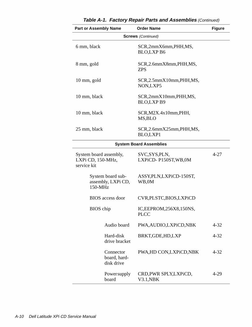
A-10 Dell Latitude XPi CD S
Screws (Continued)
6 mm, black SCR,2mmX6mm,PHH,MS,BLO,LXP B6
8 mm, gold SCR,2.6mmX8mm,PHH,MS,ZPS
10 mm, gold SCR,2.5mmX10mm,PHH,MS,NON,LXP5
10 mm, black SCR,2mmX10mm,PHH,MS,BLO,LXP B9
10 mm, black SCR,M2X.4x10mm,PHH,MS,BLO
25 mm, black SCR,2.6mmX25mm,PHH,MS,BLO,LXP1
System Board Assemblies
System board assembly, LXPi CD, 150-MHz, service kit
SVC,SYS,PLN,LXPiCD- P150ST,WB,0M
4-27
System board sub-assembly, LXPi CD, 150-MHz
ASSY,PLN,LXPiCD-150ST,WB,0M
BIOS access door CVR,PLSTC,BIOS,LXPiCD
BIOS chip IC,EEPROM,256X8,150NS,PLCC
Audio board PWA,AUDIO,LXPiCD,NBK 4-32
Hard-disk drive bracket
BRKT,GDE,HD,LXP 4-32
Connector board, hard-disk drive
PWA,HD CON,LXPiCD,NBK 4-32
Power supply board
CRD,PWR SPLY,LXPiCD,V3.1,NBK
4-29
Table A-1. Factory Repair Parts and Assemblies (Continued)
Part or Assembly Name Order Name Figure
ervice Manual

System Board Assemblies (Continued)
System board, 150-MHz
PWA,PLN,LXPiCD-150ST,NBK
I/O interface cable
CBL,I/O TO M/B,LXPiCD A-7
Bracket, I/O BRKT,I/O,LXPi
Serial EMI clip, I/O
CLP,EMI,SER,I/O,XPiCD
Docking EMI clip, I/O
CLP,EMI,DOCK,I/O,XPiCD
Diskette, field service
DSK,FLD SERV,F3,US, LXP
Technical booklet, service
DOC,SERV,GUIDE,LXPi
Trackball
Optical trackball assembly SVC,ASSY,TBALL/SWT,LXPi+CD
4-11
Trackball interface cable
CBL,TBALL,LXPi+CD 4-11
Trackball subassembly
SUBASSY,TBALL,OPTICAL,LXPiCD
Trackball board
PWA,TBALL,OPTICAL,LXPiCD
A-2
Trackball TBALL,OPTICAL,LXPiCD A-2
Trackball button board
SUBASSY,TBALL,SWT BD,LXPiCD
A-2
Technical booklet DOC,SERV,GUIDE,LXPi
Table A-1. Factory Repair Parts and Assemblies (Continued)
Part or Assembly Name Order Name Figure
Factory Repair Parts A-11

A-12 Dell Latitude XPi CD S
Exploded Views of Components and Assemblies
Figure A-1. Exploded View—Display Assembly
display assembly bezel
latch
LCD panel
LCD power cable
interface cable
LCD inverter board
display assembly case
EMI shield
display assembly hinges (2)
hinge covers (2)
ervice Manual

keyboard
almrest
4 mm
.
Figure A-2. Exploded View—Palmrest Assembly
keyboard cables (2)
trackball interface cable
trackball
p
plastic housing
trackball button board
palmrest brace
trackball ring
trackball board connector J1
CD-ROMEMI clip
A6 (4 mm)
A7 (4 mm) A8 (4 mm)
A9 (4 mm)
Factory Repair Parts A-13

A-14 Dell Latitude XPi CD S
.
Figure A-3. Exploded View—Bottom Case Assembly
bottom case assembly
system board assembly
memory compartment cover
I/O bracket clip
superpart assembly
3.1-V power supply
spreader plate
diskette/CD-ROM assembly
audio board
key buoy plate
I/O panel dust cover
dust cover for the Advanced Port Replicator
superpart serial EMI clip
superpartdocking EMI clip
ervice Manual

r bot-or,
the
d eat-rier
Hard-Disk Drive The hard-disk drive resides in a carrier that mounts inside the computer’s hard-disk drive bay. Four screws secure the drive inside the carrier. A mylainsulator provides electrical insulation between the hard-disk drive and thetom of its carrier. To remove the hard-disk drive and hard-disk drive insulatfollow these steps:
1. Remove the hard-disk drive assembly.
See “Hard-Disk Drive Assembly” in Chapter 4.
2. Place the hard-disk drive assembly right side up on the work surface, and remove the four screws that secure the drive in its carrier.
3. Rotate the front of the drive toward the back of the carrier far enough to expose the connector on the back of the drive.
4. Carefully pry the flex cable connector away from the hard-disk drive interface connector on the back of the drive.
5. Lift the hard-disk drive out of its carrier.
6. Remove the hard-disk drive insulator, if necessary.
With the hard-disk drive removed, lift the insulator straight up out of thecarrier. The 17-mm hard-disk drives also have a foam spacer on top ofinsulator (not shown).
To avoid possible damage to components on the hard-disk drive’s integratecontroller board, hold the drive at approximately a 45-degree angle while rtaching the interface cable. Then rotate the drive toward the front of its caruntil it is seated in its original position.
CAUTION: Rotating the hard-disk drive too far can damage theshort flex cable that connects the hard-disk drive to the systemboard’s hard-disk drive interface connector. Do not rotate the drivefarther than necessary to disconnect the cable from the back of thedrive.
Factory Repair Parts A-15

A-16 Dell Latitude XPi CD S
The the is
. The
irst he the
Lift
utton
alm-
ard
CD-ROM Drive The CD-ROM drive is attached to the CD-ROM/diskette drive bracket. See“Diskette/CD-ROM Drive Assembly” in Chapter 4 for instructions about removing the diskette/CD-ROM assembly from the bottom case assembly.CD-ROM flex cable is threaded through a slot in the drive bracket. Removefour screws that hold the CD-ROM to the drive bracket. Slide the CD-ROMflex cable out of the slot in the bracket holding the CD-ROM. The CD-ROMreplaced as a unit and is not disassembled.
Diskette Drive The diskette drive is attached to the CD-ROM/diskette drive bracket. See “Diskette/CD-ROM Drive Assembly” in Chapter 4 for instructions about removing the diskette/CD-ROM assembly from the bottom case assembly.Remove three screws to separate the diskette drive from the drive bracketdiskette drive is replaced as a unit and is not disassembled.
Palmrest Assembly Components To remove and replace a component of the palmrest assembly, you must fremove the assembly as described in “Palmrest Assembly” in Chapter 4. Tsubsections that follow provide removal procedures for the components oftrackball assembly. See Figure A-2.
Trackball Turn the trackball board over. Rotate the retaining ring counter-clockwise. the trackball out of the recess in the trackball holder.
Trackball Interface CableGently disconnect the end of the cable from connector J1 on the trackball bboard.
Trackball Button BoardRemove retaining screw A6 (see Figure A-2), and lift the board out of the prest assembly. When replacing the board, fit the two small switches on theunderside of the board into the recesses in the palmrest.
Palmrest BraceRemove screws A-7 through A-9 (see Figure A-2). Gently pull the brace towthe front, and lift the brace away from the palmrest.
ervice Manual
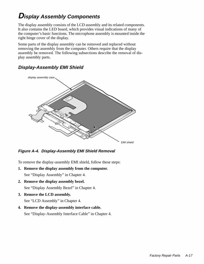
ents. f e the
dis-
Display Assembly ComponentsThe display assembly consists of the LCD assembly and its related componIt also contains the LED board, which provides visual indications of many othe computer’s basic functions. The microphone assembly is mounted insidright hinge cover of the display.
Some parts of the display assembly can be removed and replaced withoutremoving the assembly from the computer. Others require that the display assembly be removed. The following subsections describe the removal of play assembly parts.
Display-Assembly EMI Shield
Figure A-4. Display-Assembly EMI Shield Removal
To remove the display-assembly EMI shield, follow these steps:
1. Remove the display assembly from the computer.
See “Display Assembly” in Chapter 4.
2. Remove the display assembly bezel.
See “Display Assembly Bezel” in Chapter 4.
3. Remove the LCD assembly.
See “LCD Assembly” in Chapter 4.
4. Remove the display-assembly interface cable.
See “Display-Assembly Interface Cable” in Chapter 4.
display assembly case
EMI shield
Factory Repair Parts A-17

A-18 Dell Latitude XPi CD S
ull-ase
hield ase.
s:
5. Remove the LCD-inverter-board.
See “LCD-Inverter-Board Interface Cable” in Chapter 4.
6. Remove the display assembly base.
See “Display Assembly Base” later in this chapter.
7. Remove the display-assembly EMI shield.
The EMI shield is held in place by tabs along the upper and lower edges. Ping the center of the shield slightly away from the display assembly will relethe tabs.
To replace an EMI shield, carefully orient the replacement EMI shield in thesame position as the original shield. Make sure that all screw holes in the sare aligned with their corresponding screw holes in the display assembly c
Display Assembly Base To remove the display assembly base (see Figure 4-14), follow these step
1. Remove the display assembly from the computer.
See “Display Assembly” in Chapter 4.
2. Remove both hinge covers.
See “Hinge Covers” in Chapter 4.
3. Rotate the display assembly hinges so that they point away from the display assembly at approximately 180 degrees.
4. Remove the display assembly bezel.
See “Display Assembly Bezel” in Chapter 4.
5. Remove the left hinge.
See the next subsection, “Display Assembly Hinges.”
6. Rotate the right end of the display assembly base away from the displayassembly until the base clears the right hinge.
7. Lift the display assembly base away from the left hinge.
8. Disengage the display-assembly interface cable from the slot in the base.
ervice Manual

y e.
Display Assembly Hinges To remove a hinge (see Figure 4-14), follow these steps:
1. Remove the display assembly from the computer.
See “Display Assembly” in Chapter 4.
2. Remove the display assembly bezel.
See “Display Assembly Bezel” in Chapter 4.
3. Remove the LCD assembly.
See “LCD Panel” in Chapter 4.
4. Remove the display-assembly interface cable.
See “Display-Assembly Interface Cable” in Chapter 4.
5. Remove the hinge covers.
See “Hinge Covers” in Chapter 4.
6. Remove the display assembly base.
See the previous subsection, “Display Assembly Base.”
7. Rotate the display assembly hinges so that they point away from the display assembly case at approximately 180 degrees.
8. To remove the hinge, remove the screw securing the hinge to the displaassembly case and disengage the hinge from the display assembly cas
Factory Repair Parts A-19
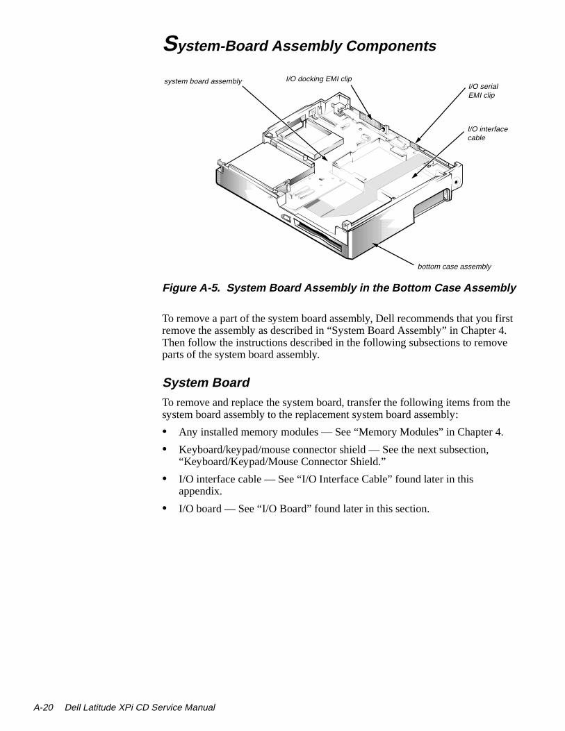
A-20 Dell Latitude XPi CD S
first r 4. ve
the
.
System-Board Assembly Components
Figure A-5. System Board Assembly in the Bottom Case Assembly
To remove a part of the system board assembly, Dell recommends that youremove the assembly as described in “System Board Assembly” in ChapteThen follow the instructions described in the following subsections to remoparts of the system board assembly.
System BoardTo remove and replace the system board, transfer the following items fromsystem board assembly to the replacement system board assembly:
• Any installed memory modules — See “Memory Modules” in Chapter 4
• Keyboard/keypad/mouse connector shield — See the next subsection,“Keyboard/Keypad/Mouse Connector Shield.”
• I/O interface cable — See “I/O Interface Cable” found later in this appendix.
• I/O board — See “I/O Board” found later in this section.
bottom case assembly
system board assembly
I/O interfacecable
I/O docking EMI clipI/O serialEMI clip
ervice Manual

oci-
/O of d off
Keyboard/Keypad/Mouse Connector Shield
Figure A-6. Keyboard/Keypad/Mouse Connector Shield Removal
Two tabs on the keyboard/keypad/mouse connector shield engage two assated slots on the I/O panel near the keyboard/keypad/mouse connector. Retaining screw D4 attaches the bottom of the shield to the bottom of the Ipanel. To remove the shield, remove retaining screw D4, rotate the bottomthe shield toward the back of the system board assembly, and lift the shielthe I/O panel.
D4 (3 mm)
keyboard/keypad/mouse connector
connector shield
3 mm
Factory Repair Parts A-21

A-22 Dell Latitude XPi CD S
I/O Interface Cable
Figure A-7. I/O Interface Cable Removal
To remove the cable, follow these steps:
1. Disconnect one end of the I/O interface cable from connector JSTDIO on the system board.
Connector JSTDIO is located on the underside of the system board.
2. Disconnect the other end of the I/O interface cable from connector JFLEX on the I/O board.
I/O interface cable
connector JFLEX
connector JSTDIO
I/O board
system board
ervice Manual

is the
I/O Board
Figure A-8. I/O Board Removal
To remove and replace the I/O board, follow these steps:
1. Remove the I/O interface cable from connector JSTDIO.
See the previous subsection in this appendix.
2. Remove the keyboard/keypad/mouse connector shield.
See “Keyboard/Keypad/Mouse Connector Shield” found earlier in this appendix.
3. Remove the four hexagonal standoff screws ST1 through ST4 that secure the serial and parallel port connectors to the I/O panel.
Use a 3/16 nut holder to remove the standoff screws.
4. Remove the side I/O bracket clip.
See “System Board Assembly” in Chapter 4.
5. Lift the I/O board away from the I/O panel.
When replacing the I/O board, make sure that the side I/O bracket clip positioned so that it rests directly on the I/O board, rather than betweenI/O board and I/O bracket (see Figure A-8).
I/O board
I/O bracket
8 mm
I/O bracket clip
ST1 (8 mm)
ST2 (8 mm)ST3 (8 mm)
ST4 (8 mm)
Factory Repair Parts A-23

A-24 Dell Latitude XPi CD S
I/O Panel
Figure A-9. I/O Panel Removal
To remove and replace the I/O panel, follow these steps:
1. Remove the I/O board.
See the previous subsection in this appendix.
2. Remove the standoff nuts ST1 through ST8
Use a 3/16 nut driver to remove standoff nuts ST1 through ST6 and a 7/32 nut driver for ST7 and ST8.
3. Remove screw D5.
4. Remove the I/O bracket from the system board.
system board
I/O bracket
8 mm
ST5ST6ST7 (4 mm)
4 mm3 mm
D5 (3 mm)
ST4ST3 ST2 ST1
ST8 (4 mm)
NOTE: ST1–ST8 are 8-mm standoff nuts
ervice Manual

stem he ase
d
tem
Bottom-Case Assembly Components
Figure A-10. Bottom-Case Assembly Components
To remove parts of the bottom case assembly, you must first remove the syboard assembly as described in “System Board Assembly” in Chapter 4. Tsubsections that follow describe the removal and replacement of bottom-cassembly components.
Main Battery InsulatorThe main battery insulator insulates the main battery from the system boarassembly. To remove the main battery insulator, lift it off the main battery compartment.
NOTE: The main battery insulator sometimes comes out as part of the sysboard assembly. If this happens, follow the instructions in “System Board Assembly” in Chapter 4.
bottom case assembly
spreader plate
power button
main battery insulator
Factory Repair Parts A-25

A-26 Dell Latitude XPi CD S
s far lade ket. ower
Power Button and Power-Button Mounting Bracket
Figure A-11. Power Button and Power-Button Mounting Bracket Removal
Two tabs attach the power button to the power-button mounting bracket. Toremove the power button and its mounting bracket, slide the power button aas it will go toward the back of the bottom case assembly. Use a small flat-bscrewdriver or similar device to press the two tabs out of the mounting bracLift the mounting bracket out of the bottom case assembly; then press the pbutton out of the hole in the side of the bottom case assembly.
power buttonmounting bracket
power button
ervice Manual

e plate e fits te by
Spreader and Keel Plates
Figure A-12. Spreader and Keel Plate Removal
Remove the spreader plate by lifting it from the bottom case assembly. Thspreader plate fits easily over plastic projections and screw holes. The keelis in the center of the bottom case, below the spreader plate. The keel platover a small peg and a semicircular plastic projection. Remove the keel plalifting it out of the bottom case assembly.
spreader plate
bottom case assembly
keel plate
Factory Repair Parts A-27

A-28 Dell Latitude XPi CD S
ervice Manual
Appendix BSystem Setup Options
n-n the
the
n the
file
You may want to customize the configuration of your computer. This appedix describes how to change the system setup options stored in NVRAM osystem board.
You can access these options in two ways:
• Using the Dell Control Center
• Using the MS-DOS–based version of the system setup options, called System Setup program
Accessing the Dell Control Center
Figure B-1. Dell Control Center Icon
To access system setup options, double-click the Dell Control Center icon iDell Accessories program group in Windows.
Each button in the Dell Control Center window corresponds to a particular group of system setup options. The Dell Control Center has a detailed helpthat explains each setup option.
Figure B-2. Dell Control Center Window
System Setup Options B-1

B-2 Dell Latitude XPi CD S
sus-tes
Accessing the System Setup ProgramNOTE: If the System Setup program is running when the computer enters pend mode, the computer exits the System Setup program and then activasuspend mode.
To enter the System Setup program, hold down the <CTRL> and <ALT> keys and press the <ENTER> key, or press the <FN> and <F1> keys.
ervice Manual

System Setup Screens
Figure B-3. System Setup Screens
Time: 13:17:02Date: Mon Feb 12, 1997 This category sets the time in 24-hour format (hours:min-utes:seconds) for the internal clock/calendar.
To change the value in a field, enter digits or use the left- or right-arrow key to decrease or increase the value.
Changes take effect immediately.
Esc exitchange values Alt-B reboot
Dell Computer Corporation
Page 1 of 2 Dell Latitude XPi CD System Setup
Tab,Shift-Tab change fields change values Esc exit
BIOS Version: A XX XXX
Dell Computer Corporation
Page 2 of 2 Dell Latitude XPi CD System Setup
Alt-P nextTab,Shift-Tab change fields
BIOS Version: A XX
Alt-P next Alt-B reboot
Internal Hard Drive:Diskette Drive A:
Boot Speed:Boot Sequence:
Speaker Volume:Keyboard Click:
Serial Port:Infrared Data Port:
Parallel Mode:Integrated Trackball:Upper PC Card Socket:Lower PC Card Socket:
Monitor Toggle:
Replicator SCSI:Replicator Network:
Ring Speed:
1216 MB3.5 inch, 1.44 MB150 MHzDiskette FirstHighDisabledCOM1DisabledBidirectionalEnabledNot InstalledNot installedEnabled
EnabledEnabled16 mbps
Power Management:Display Time-Out:
Disk Time-Out:Suspend Time-Out:
S2D Time-Out:Smart CPU Mode:
Brightness:
Ring/Event Resume:Alarm Resume:
Display Close:System Switch:
Battery Status:IntelliSpin:
Primary Password:Admin Password:
ACDisabledDisabledDisabledDisabledDisabledDisabledHigh
BATTERYEnabled4 minutes1 minute10 minutes8 hoursEnabledLow
When set to DISABLED, this cate-gory disables all power management features.
The default setting is ENABLED.
A change in this category takes
Microprocessor:System Memory:
Video Memory:External Cache:
Expansion Device:Service Tag:
Asset Tag:
Pentium-15016 MB1.1 MB256 KBNot installedXXXXXXXXXX
Pentium-15016 MB1.1 MB256 KBNot installedXXXXXXXXXX
Microprocessor:System Memory:
Video Memory:External Cache:
Expansion Device:Service Tag:
Asset Tag:
EnabledEnabledSUSPENDON/OFFDisplayHigh Performance
DisabledDisabled
System Setup Options B-3
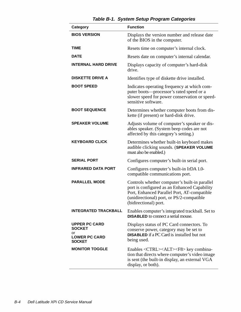
B-4 Dell Latitude XPi CD S
-
Table B-1. System Setup Program Categories
Category Function
BIOS VERSION Displays the version number and release dateof the BIOS in the computer.
TIME Resets time on computer’s internal clock.
DATE Resets date on computer’s internal calendar.
INTERNAL HARD DRIVE Displays capacity of computer’s hard-disk drive.
DISKETTE DRIVE A Identifies type of diskette drive installed.
BOOT SPEED Indicates operating frequency at which com-puter boots—processor’s rated speed or a slower speed for power conservation or speedsensitive software.
BOOT SEQUENCE Determines whether computer boots from dis-kette (if present) or hard-disk drive.
SPEAKER VOLUME Adjusts volume of computer’s speaker or dis-ables speaker. (System beep codes are not affected by this category’s setting.)
KEYBOARD CLICK Determines whether built-in keyboard makes audible clicking sounds. (SPEAKER VOLUME must also be enabled.)
SERIAL PORT Configures computer’s built-in serial port.
INFRARED DATA PORT Configures computer’s built-in IrDA 1.0-compatible communications port.
PARALLEL MODE Controls whether computer’s built-in parallel port is configured as an Enhanced Capability Port, Enhanced Parallel Port, AT-compatible (unidirectional) port, or PS/2-compatible (bidirectional) port.
INTEGRATED TRACKBALL Enables computer’s integrated trackball. Set toDISABLED to connect a serial mouse.
UPPER PC CARD SOCKETorLOWER PC CARD SOCKET
Displays status of PC Card connectors. To conserve power, category may be set to DISABLED if a PC Card is installed but not being used.
MONITOR TOGGLE Enables <CTRL><ALT><F8> key combina-tion that directs where computer’s video image is sent (the built-in display, an external VGA display, or both).
ervice Manual

r
REPLICATOR SCSI Configures computer for use with Advanced Port Replicator. SCSI drivers will load auto-matically if a SCSI device is connected.
REPLICATOR NETWORK Enabling this category and installing is_net.exe utility allow user to configure net-work drivers for use with Advanced Port Replicator.
RING SPEED Configures the ring speed for the Advanced Port Replicator.
MICROPROCESSOR Displays type of microprocessor installed.
SYSTEM MEMORY Displays amount of system memory.
VIDEO MEMORY Displays amount of video memory.
EXTERNAL CACHE Displays amount of external cache memory.
EXPANSION DEVICE Shows the type of Dell Latitude Advanced Port Replicator that is attached to the com-puter. There are no user-selectable settings fothis option.
SERVICE TAG Displays computer’s five-character service tag number.
ASSET TAG Displays computer’s customer-programmable asset tag. This category only appears if user has entered an asset tag number.
POWER MANAGEMENT Enables computer’s power conservation fea-tures.
BATTERY One of the categories of POWER MANAGE-MENT. Set different time-outs for the following options when the computer operates from bat-tery power: DISPLAY TIME-OUT, DISK TIME-OUT, SUSPEND TIME-OUT, S2D TIME-OUT, SMART CPU MODE, and BRIGHTNESS.
Changing the BATTERY option takes effect immediately (rebooting is not required)
AC One of the categories of POWER MANAGE-MENT. Set different time-outs for the following options when operating the computer from alternating current (AC) power: DISPLAY TIME-OUT, DISK TIME-OUT, SUSPEND TIME-OUT, S2D TIME-OUT, SMART CPU MODE, and BRIGHTNESS.
Table B-1. System Setup Program Categories (Continued)
Category Function
System Setup Options B-5

B-6 Dell Latitude XPi CD S
.
l
DISPLAY TIME-OUT Determines how long computer operates with-out detecting I/O activity before display is switched off to conserve battery power. This option should be disabled if software compati-bility problems occur.
DISK TIME-OUT Determines how long hard-disk drive is idle before drive motor turns off to conserve bat-tery power.
SUSPEND TIME-OUT Determines how long computer is idle before suspend mode is activated.
S2D TIME-OUT Determines how long computer is idle before suspend-to-disk mode is activated.
SMART CPU MODE Allows microprocessor to slow down when inactive. If software runs particular slowly, this category should be set to DISABLE .
BRIGHTNESS Determines the brightness used when runningfrom the battery.
RING/EVENT RESUME Determines if computer exits suspend mode if an installed modem receives an incoming call.
ALARM RESUME Determines if computer resumes normal oper-ation from suspend or standby mode if an alarm from RTC is detected.
DISPLAY CLOSE Indicates whether the computer enters suspendmode when the display is closed or whether only the display is turned off when the display is closed. SUSPEND (the default) indicates the computer is in suspend mode when the displayis closed. ACTIVE turns off the display, but does not put the computer into suspend mode
SYSTEM SWITCH Determines if power switch serves as a con-ventional on/off switch, or toggles computer between suspend-to-disk operation and normaoperation.
BATTERY STATUS Displays percentage of charge remaining in battery.
Table B-1. System Setup Program Categories (Continued)
Category Function
ervice Manual

e
-
INTELLISPIN Compensates for unbalanced CDs that cause thcomputer to vibrate when the CD-ROM drive is in use. Allows use of discs that might otherwise be unreadable. Available for CD-ROM drives with speeds of 6X or higher. HIGH PERFOR-MANCE (the default), lets the CD-ROM drive run at the highest speed. VARIABLE automati-cally lowers the CD-ROM’s speed to reduce or stop the vibration.
PRIMARY PASSWORD Displays the current status of the primary password and allows you to assign or change this password.
ADMIN PASSWORD Displays current status of computer’s adminis-trator password security feature. Also used to assign and verify a new administrator pass-word.
Table B-1. System Setup Program Categories (Continued)
Category Function
System Setup Options B-7

B-8 Dell Latitude XPi CD S
ervice Manual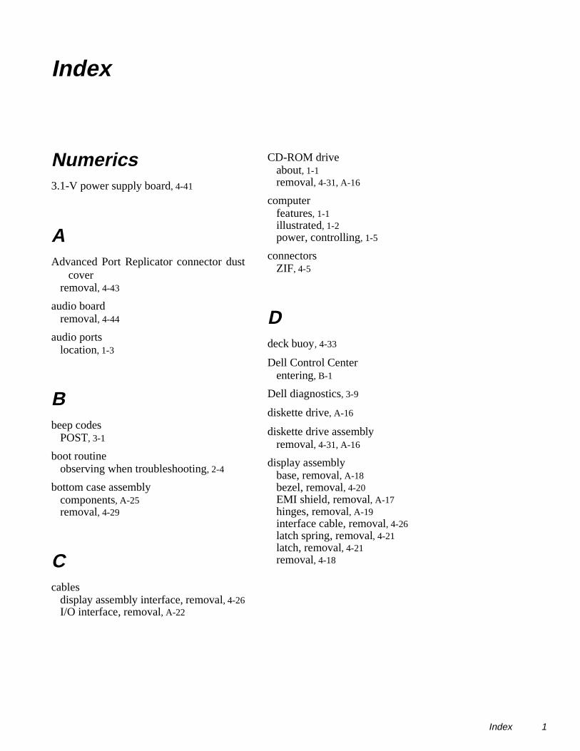
Index
Numerics3.1-V power supply board, 4-41
AAdvanced Port Replicator connector dust
coverremoval, 4-43
audio boardremoval, 4-44
audio portslocation, 1-3
Bbeep codes
POST, 3-1
boot routineobserving when troubleshooting, 2-4
bottom case assemblycomponents, A-25removal, 4-29
Ccables
display assembly interface, removal, 4-26I/O interface, removal, A-22
CD-ROM driveabout, 1-1removal, 4-31, A-16
computerfeatures, 1-1illustrated, 1-2power, controlling, 1-5
connectorsZIF, 4-5
Ddeck buoy, 4-33
Dell Control Centerentering, B-1
Dell diagnostics, 3-9
diskette drive, A-16
diskette drive assemblyremoval, 4-31, A-16
display assemblybase, removal, A-18bezel, removal, 4-20EMI shield, removal, A-17hinges, removal, A-19interface cable, removal, 4-26latch spring, removal, 4-21latch, removal, 4-21removal, 4-18
Index 1

2 Dell Latitud
d
Eerror messages, system, 3-3
ESD, 4-2
exploded viewbottom assembly, A-14LCD assembly, A-12top assembly, A-13
external visual inspection, 2-1
Ggrounding strap, 4-3
Hhard-disk drive, A-15
hard-disk drive assemblyremoval, 4-7
hinge coversremoval, 4-25
II/O board, A-23
I/O interface cableremoval, 4-41, A-22
I/O panel, A-24
I/O panel dust coverremoval, 4-42
indicator panel, 1-3
initial proceduressystem error messages, 3-3troubleshooting, 2-1
initializationerror messages, 3-9
IrDA communications portlocation, 1-2
IRQ line assignmentslist of, 1-6
Kkeel plate, A-27
key combinationsto enter System Setup program, B-2
keyboard assemblyremoval, 4-14
keyboard/keypad/mouse connector shielremoval, A-21
LLCD inverter board, 4-24
LCD panelremoval, 4-22
LEDs, 1-3
low-battery warnings, 1-4
Mmain battery
removal, 4-3
memory compartment coverremoval, 4-8
memory modulecapacities, 1-1removal, 4-9
messages, system errorlist of, 3-3
messages See system error messages
microphone/switch assemblyremoval, 4-28
e XPi CD Service Manual

Ppalmrest assembly
components, A-16removal, 4-10
palmrest brace, A-16
PC Cardtypes supported, 1-1
POST beep codesabout, 3-1list of, 3-1
power buttonremoval, A-26
power-button mounting bracket, A-26
precautions, 4-2
Rreserve battery
removal, 4-36
Sscrew identification and tightening, 4-4
socketsmemory module, 4-9
specificationstechnical, 1-7
spreader plate, A-27
subsystemstesting, 3-8
superpart assemblycomponents, 4-36removal, 4-34
systemconfiguring, B-4features, 1-1locations, 1-2
system board assemblyremoval, 4-34, 4-38
system board components, A-20
system configuration information, B-3
system error messagesabout, 3-3list of, 3-3
system setup options, B-1
System Setup programentering, B-2screens, B-3settings, B-4
Ttechnical specifications, 1-7
tilt-support feetremoval, 4-16
tools required, 4-2, A-1
trackballassembly removal, 4-13, A-16button board removal, A-16interface cable, A-16
troubleshootingboot routine interpretation, 2-4external visual inspection, 2-1initial user contact, 2-1
Uuser contact
initial, 2-1
Index 3

4 Dell Latitud
Vvisual inspection
external, 2-1
ZZIF connectors, 4-5
e XPi CD Service Manual