Embed Size (px)
Citation preview

Lynx Manual
Revision History
Style Sheet is: X:\Company\SmartMasters\Orion
Filenames are: X:\Company\Manuals\ReferenceManual\Components\Lynx\RevA\LynxManual.lwpX:\Company\Manuals\ReferenceManual\Components\Lynx\RevA\LynxTitlePage
X:\Company\Manuals\ReferenceManual\Components\Lynx\RevB\LynxManual.lwp
X:\Company\Manuals\ReferenceManual\Components\Lynx\RevB\LynxTitlePage
Rev Date Author Description
A 16 Aug 99 Mark Hayman Initial release.B 22 Mar 00 Brad Tavner Rev E Chassis updates.
Approval: ________________________________

44Outgoing Packets . . . . . . . . . . . . . . . . . . . . . . . . . . . . . . . . . . . . . . . . . . . . . . . . . . . . . . . . . . . . . . . . . . . . . . . . . . . . . . . . . . . . . . . . . .
42CRC for the Packets . . . . . . . . . . . . . . . . . . . . . . . . . . . . . . . . . . . . . . . . . . . . . . . . . . . . . . . . . . . . . . . . . . . . . . . . . . . . . . . . . . . . . . .
41Description of NMXP Packets . . . . . . . . . . . . . . . . . . . . . . . . . . . . . . . . . . . . . . . . . . . . . . . . . . . . . . . . . . . . . . . . . . . . . . . . . . . . .
39Appendix B - Libra Data Format . . . . . . . . . . . . . . . . . . . . . . . . . . . . . . . . . . . . . . . . . . . . . . . . . . . . . . . . . . . . . . . . . . . . . . . . .
37Appendix A - Connector Pinouts . . . . . . . . . . . . . . . . . . . . . . . . . . . . . . . . . . . . . . . . . . . . . . . . . . . . . . . . . . . . . . . . . . . . . . .
33Internal Configuration Options . . . . . . . . . . . . . . . . . . . . . . . . . . . . . . . . . . . . . . . . . . . . . . . . . . . . . . . . . . . . . . . . . . . . . . . . . . . . .
32Software & Firmware Updates . . . . . . . . . . . . . . . . . . . . . . . . . . . . . . . . . . . . . . . . . . . . . . . . . . . . . . . . . . . . . . . . . . . . . . . . . . . .
31HRD Configuration Port . . . . . . . . . . . . . . . . . . . . . . . . . . . . . . . . . . . . . . . . . . . . . . . . . . . . . . . . . . . . . . . . . . . . . . . . . . . . . . . . . . . .
31Maintenance . . . . . . . . . . . . . . . . . . . . . . . . . . . . . . . . . . . . . . . . . . . . . . . . . . . . . . . . . . . . . . . . . . . . . . . . . . . . . . . . . . . . . . . . . . . . . . . .
318. Servicing . . . . . . . . . . . . . . . . . . . . . . . . . . . . . . . . . . . . . . . . . . . . . . . . . . . . . . . . . . . . . . . . . . . . . . . . . . . . . . . . . . . . . . . . . . . . . . . . . . . . . . .
27Configuration Menus . . . . . . . . . . . . . . . . . . . . . . . . . . . . . . . . . . . . . . . . . . . . . . . . . . . . . . . . . . . . . . . . . . . . . . . . . . . . . . . . . . . . . . .
25Accessing the HRD24 Setup . . . . . . . . . . . . . . . . . . . . . . . . . . . . . . . . . . . . . . . . . . . . . . . . . . . . . . . . . . . . . . . . . . . . . . . . . . . . . .
25Overview . . . . . . . . . . . . . . . . . . . . . . . . . . . . . . . . . . . . . . . . . . . . . . . . . . . . . . . . . . . . . . . . . . . . . . . . . . . . . . . . . . . . . . . . . . . . . . . . . . . . .
257. HRD24 Firmware Configuration . . . . . . . . . . . . . . . . . . . . . . . . . . . . . . . . . . . . . . . . . . . . . . . . . . . . . . . . . . . . . . . . . . . . .
23Basic troubleshooting . . . . . . . . . . . . . . . . . . . . . . . . . . . . . . . . . . . . . . . . . . . . . . . . . . . . . . . . . . . . . . . . . . . . . . . . . . . . . . . . . . . . . .
21Signal input . . . . . . . . . . . . . . . . . . . . . . . . . . . . . . . . . . . . . . . . . . . . . . . . . . . . . . . . . . . . . . . . . . . . . . . . . . . . . . . . . . . . . . . . . . . . . . . . .
21Introduction . . . . . . . . . . . . . . . . . . . . . . . . . . . . . . . . . . . . . . . . . . . . . . . . . . . . . . . . . . . . . . . . . . . . . . . . . . . . . . . . . . . . . . . . . . . . . . . . .
216. Hardware Setup . . . . . . . . . . . . . . . . . . . . . . . . . . . . . . . . . . . . . . . . . . . . . . . . . . . . . . . . . . . . . . . . . . . . . . . . . . . . . . . . . . . . . . . . . . . .
18Testing the Lynx Modules . . . . . . . . . . . . . . . . . . . . . . . . . . . . . . . . . . . . . . . . . . . . . . . . . . . . . . . . . . . . . . . . . . . . . . . . . . . . . . . . .
17Installation . . . . . . . . . . . . . . . . . . . . . . . . . . . . . . . . . . . . . . . . . . . . . . . . . . . . . . . . . . . . . . . . . . . . . . . . . . . . . . . . . . . . . . . . . . . . . . . . . .
17Introduction . . . . . . . . . . . . . . . . . . . . . . . . . . . . . . . . . . . . . . . . . . . . . . . . . . . . . . . . . . . . . . . . . . . . . . . . . . . . . . . . . . . . . . . . . . . . . . . . .
175. Getting Started . . . . . . . . . . . . . . . . . . . . . . . . . . . . . . . . . . . . . . . . . . . . . . . . . . . . . . . . . . . . . . . . . . . . . . . . . . . . . . . . . . . . . . . . . . . . .
15Satellite Modem Module . . . . . . . . . . . . . . . . . . . . . . . . . . . . . . . . . . . . . . . . . . . . . . . . . . . . . . . . . . . . . . . . . . . . . . . . . . . . . . . . . . .
13Comms Controller Module . . . . . . . . . . . . . . . . . . . . . . . . . . . . . . . . . . . . . . . . . . . . . . . . . . . . . . . . . . . . . . . . . . . . . . . . . . . . . . . . .
9HRD24 Module . . . . . . . . . . . . . . . . . . . . . . . . . . . . . . . . . . . . . . . . . . . . . . . . . . . . . . . . . . . . . . . . . . . . . . . . . . . . . . . . . . . . . . . . . . . . . .
7Overview of the Hardware . . . . . . . . . . . . . . . . . . . . . . . . . . . . . . . . . . . . . . . . . . . . . . . . . . . . . . . . . . . . . . . . . . . . . . . . . . . . . . . . . . .
74. Technical Description . . . . . . . . . . . . . . . . . . . . . . . . . . . . . . . . . . . . . . . . . . . . . . . . . . . . . . . . . . . . . . . . . . . . . . . . . . . . . . . . . . . . .
53. Unpacking & Post Delivery Inspection . . . . . . . . . . . . . . . . . . . . . . . . . . . . . . . . . . . . . . . . . . . . . . . . . . . . . . . . . . . .
32. Organization of this Manual . . . . . . . . . . . . . . . . . . . . . . . . . . . . . . . . . . . . . . . . . . . . . . . . . . . . . . . . . . . . . . . . . . . . . . . . . . . .
11. Introduction . . . . . . . . . . . . . . . . . . . . . . . . . . . . . . . . . . . . . . . . . . . . . . . . . . . . . . . . . . . . . . . . . . . . . . . . . . . . . . . . . . . . . . . . . . . . . . . . . . .
Table of Contents
- i -

75Appendix G - External Cable Drawings . . . . . . . . . . . . . . . . . . . . . . . . . . . . . . . . . . . . . . . . . . . . . . . . . . . . . . . . . . . . . .
71Appendix F - Upgrading HRD24 firmware using ZOC . . . . . . . . . . . . . . . . . . . . . . . . . . . . . . . . . . . . . . . . . .
67Appendix E - ViewDat . . . . . . . . . . . . . . . . . . . . . . . . . . . . . . . . . . . . . . . . . . . . . . . . . . . . . . . . . . . . . . . . . . . . . . . . . . . . . . . . . . . . . . . .
61System Filter Values . . . . . . . . . . . . . . . . . . . . . . . . . . . . . . . . . . . . . . . . . . . . . . . . . . . . . . . . . . . . . . . . . . . . . . . . . . . . . . . . . . . . . .
61Response . . . . . . . . . . . . . . . . . . . . . . . . . . . . . . . . . . . . . . . . . . . . . . . . . . . . . . . . . . . . . . . . . . . . . . . . . . . . . . . . . . . . . . . . . . . . . . . . . . .
61Appendix D - Filter Response Plots, Poles & Zeroes . . . . . . . . . . . . . . . . . . . . . . . . . . . . . . . . . . . . . . . . . . .
55Appendix C - Instrument Log Messages . . . . . . . . . . . . . . . . . . . . . . . . . . . . . . . . . . . . . . . . . . . . . . . . . . . . . . . . . . . . .
49Status Packet . . . . . . . . . . . . . . . . . . . . . . . . . . . . . . . . . . . . . . . . . . . . . . . . . . . . . . . . . . . . . . . . . . . . . . . . . . . . . . . . . . . . . . . . . . . . . .
45Incoming Packets . . . . . . . . . . . . . . . . . . . . . . . . . . . . . . . . . . . . . . . . . . . . . . . . . . . . . . . . . . . . . . . . . . . . . . . . . . . . . . . . . . . . . . . . . .
Table of Contents
- ii -

1. IntroductionCongratulations on your choice of the Lynx digitiser, a part of the Nanometrics Libra SatelliteSeismograph System. As you use your new Lynx digitiser we know you will appreciate the manyfeatures that provide excellent performance.
It is very important to understand how the Lynx digitiser operates before you use it. On thefollowing pages you will find a wealth of information regarding all aspects of the Lynx digitiser.Please read the instructions carefully.
If you have problems or need technical support, please submit requests for technical support bye-mail or fax. This permits you to fully explain your problem and include "evidence" as it allows usto submit your problem to the most knowledgeable person for reply.
by e-mail: [email protected]
by fax: To: Support at fax (613) 592-5929
by phone: Please ask for Support at (613) 592-6776
Nanometrics Inc.250 Herzberg Road
Kanata, Ontario CanadaK2K 2A1
Introduction
Lynx Manual 1

This page intentionally left blank.

2. Organization of this ManualThis manual is organized in ten major sections:
Chapter 1 IntroductionIntroductory notes to this manual.
Chapter 2 Organization of this ManualNotes on how to use this manual.
Chapter 3 Unpacking and Post Delivery Inspection Identification of the components you have purchased. It also references an"as-shipped" section.
Chapter 4 Technical DescriptionDescription of features and technical specifications of the Lynx.
Chapter 5 Getting StartedRecommendations for using the digitiser for the first time.
Chapter 6 Hardware setupHardware setup instructions.
Chapter 7 Software configurationDescription of software configuration parameters and configuration menus.
Chapter 8 ServicingRecommended maintenance and repair procedures, including firmwareupdate instructions.
Appendices These list mostly tabular material such as error messages, and pinconnections.
Lynx Manual 3
Organization of this Manual

This page intentionally left blank.

3. Unpacking & Post Delivery InspectionOpen and inspect the shipment for possible damage. Carefully check each item for damage ordefects. The following list includes items generally included with Lynx. This list might vary fromapplication to application. To find out the exact list of items included in your shipment refer to theshipping documents.
The system should have the following contents:
1. Lynx digitiser
2. GPS antenna and mounting bracket
3. GPS antenna cable
4. Satellite antenna cables
5. Power cable
6. Satellite antenna
7. Lynx digitiser manual
8. As-shipped Sheet
9. Release Notes (if applicable)
10. CD with digitiser test program, configuration user interface software and firmwarecode
Checking the As-Shipped Sheets
As written, this manual covers the Lynx digitiser. Please study the as-shipped data sheet todetermine the exact configuration of the digitiser. The as-shipped sheet lists the serial numbers ofthe parts shipped, the exact hardware configuration and calibration constants associated with yourhardware. It also includes a hard copy of the as-shipped sheet of the Lynx digitiser. This willdetermine how your Lynx digitiser operates when first turned on. Several features may have beenadded to the digitiser since this manual was released. Such new features are described in theRelease Notes which have precedence over the information in the manual.
Backup
It is strongly recommended that you backup the CD or the diskette.
Lynx Manual 5
Unpacking & Post Delivery Inspection

This page intentionally left blank.

4. Technical Description
Overview of the HardwareThe Lynx satellite telemetry digitiser is specifically intended to be deployed with satellite telemetryseismograph networks with error correction.
The Lynx integrates all necessary hardware to digitise the analog signal produced by theseismometer, to time-stamp digital data, to transmit the data and the SOH information to the centralsite over a VSAT link and to receive messages from the acquisition centre. It includes a 24 bit highresolution digitiser, high precision GPS timing subsystem, serial and Ethernet ports for externalinstrumentation, a satellite modem for both inbound and outbound links and all necessaryhardware for the interconnection and operation of all of the above.
The transmission protocol used over the VSAT link includes UDP / TCP / IP. Essentially each Lynxdigitiser can be considered as a remote node of a wide area network. The Ethernet port fullysupports UDP & TCP/IP protocols such as E-mail, ftp, and sockets.
The following block diagram provides you with a clear view of the different hardware mo dulesintegrated in Lynx and the way it is connected with external components of the remote site. TheHRD24 digitiser, Comms Controller board and Satellite Modem board are described in the followingsections.
Figure 1: Lynx digitiser block diagram.
The Lynx Digitiser is packaged in a rugged waterproof and environmentally resistant steel box. Allthe connectors are situated on the front plate of the box as shown in the Figure 2.
Technical Description
Lynx Manual 7
SATELLITEMODEM
COMMSCONTROLLER
HRD24
SSPB
LNB
AntennaFeedHorn
GPS Antenna
GPSPower
EthernetSOH/Comms
RF Out
RF InSignal 1
Signal 2
Lynx Digitiser Box

Figure 2: Lynx Digitiser front plate
Specifications
Supply voltage: 11 - 16 VDC,
Power consumption: < 30 watts (complete system includes digitiser and GPS)
Operating temperature: -20 to +55 degrees C
Humidity 0 to 100%
Technical Description
Lynx Manual 8

HRD24 Module
Operation
An important part of the Lynx Digitiser is a 24 bit High Resolution Digitiser module, hereafter thetext referred to as “digitiser”. It is a module which samples the seismometer output signal andassemb les it into packets of a proprietary format. The digitiser will digitise from one to six channelsof data with sample rates from 10 s/s to 1000s/s. However, the sample rate should be selectedconsidering the throughput of the communication link
Data are assembled into packets with a CRC for error detection. Each packet includes acomprehensive header which holds parameters such as the packet sequence number, time in longseconds and the oldest packet available. See the appendix for more information on the data format.
The digitiser may have two software filters. The first filter is a decimating FIR (Finite ImpulseResponse) filter which is used for low pass filtering of the data. This is always required due to thenature of Delta-Sigma converters. The second filter is an optional IIR (Infinite Impulse Response)high pass filter to remove the DC offset from the data. Appendix D shows the corner frequenciesof these software filters.
A GPS time reference provided by the comms controller module of the Lynx is used for timesynchronization.
The SETUP menu is used to configure the digitiser parameters to suit the application and to storethese parameters in the nonvolatile Flash memory chip. A full list of configurable parameters isgiven in the Configuring the Firmware chapter.
Time and output data timing
The digitiser keeps internal time which is referenced to a GPS clock. If the GPS clock is not lockedthe digitiser can free run on its own internal oscillator. When the GPS relocks, the digitiser willphase lock back onto the GPS time. All data from the digitiser is time stamped with the absoluteUTC time.
Hardware description
This section gives a brief overview of the digitiser hardware. Later sections of the manual willdefine the software. The input impedance and digitiser sensitivities are user settable parameterswhich are set through one resistor respectively for each channel. The user should refer to theas-shipped data sheet to determine the actual values for these parameters.
Differential Amplifier
There is an input differential amplifier for each channel input signal. The gain of this stage is usedto set the overall system sensitivity. Gains of between 1 and 256 are typical. A potentiometer isassociated with each input and is adjusted to give maximum common mode rejection. The inputimpedance is usually left as a high impedance input (>50K). The gain and input impedance are usersettable parameters which are set through one resistor respectively for each channel. The usershould refer to the as-shipped data sheet to get actual values for the resistors.
Analog Anti-alias Filter
The anti-alias filter requirements are quite low due to the high input sample rate used withdelta-sigma converters. The anti-alias filter is a 5th order Bessel filter to give linear phase response.A single operational amplifier generates the low pass poles. The filter has a gain of 1 and isconfigured for low noise.
Technical Description
Lynx Manual 9

Analog-digital Converter (ADC) & Digital Anti-alias Filter
A 120 dB Delta-sigma modulation ADC is used for conversion. This IC samples at a high rate,digitally filters and decimates the data, and then outputs the data to the DSP. The DSP furtherfilters and decimates the data to achieve the desired resolution. Different sample rates are achievedby decimating to a greater or lesser extent. Delta Sigma ADC output one bit of data at a high ratewhich is filtered to produce higher resolution at lower sample rates. Sample rate is traded off forresolution. This works because the delta sigma modulator has all its quantization noise atfrequencies which are later filtered out.
Figure 3: Block diagram of the digitiser module.
DAC and Calibration (Optional)
Calibration signals are obtained from a laser-trimmed precision 12 bit D/A converter chip. Undersoftware control, the calibration signal can be set to any value with a resolution of 1 in +/- 2048.Full scale is usually +/- 5V. Calibration relays switch the calibration signal to one side of thecalibration coil. Another pole on the relay grounds the other end of the calibration coil whenactive. The as-shipped sheet specifies actual calibrator parameters. When determining sensorsensitivity, allowance must be made for the wire loop resistance and the calibration coil resistance.
Output Ports
The internal hardware is controlled by ports on the TCP, several eight bit ports and someprogrammable logic. The TCP interfaces with the RS232 status bits and the universal serialcontroller (USC) for RS232 data.
When the calibration and/or active sensor control option is selected the TCP controls thecalibration DAC and two eight bit control ports. This selects the calibration port, the calibrationoutput signal level and frequency in addition to the active sensor control lines.
State-of-Health
The digitiser monitors a number of analog state-of-health (SOH) channels, six 'slow' and three 'fast'.Three of the slow channels are used internally to monitor the input voltage, the internaltemperature of the VCXO and the radio signal to noise ratio. The three ‘fast’ channels are used forsensor mass centering. The remaining channels are not used when the HRD is installed in a Lynx.The Lynx comms controller also monitors 3 external SOH channels, as discussed in the commscontroller description.
Technical Description
Lynx Manual 10

The battery level monitor has a nominal sensitivity of 24.4 mV/bit, with an offset of +0.1V as a resultof internal voltage drops.
The temperature monitors each have nominal input sensitivities of 0.217°C/bit with an offset of-61°C.
These SOH are typically sampled at 0.125Hz. The software controls how often they are logged.
The three FAST SOH channels are typically sampled at one Hz. These FAST SOH have an inputrange of ±10V and a sensitivity of 19.7mV/bit. An open input will appear as a 2.5V input. Theseinputs are used to monitor mass position in an active sensor.
The scale calibration factor is built from two constants. One is the actual sensitivity of the digitiserSOH which is expressed in millivolts per least significant bit and is a factory setting. The otherconstant is the sensitivity of the sensor. This might be expressed as "units" per volt. For example,with a temperature sensor, this might be set to 44 degrees Celsius per volt. Both of theseparameters are set in the appropriate SOH Config menu.
The offset is used to allow for the sensor not producing zero output volts when registering zero"units". The offset is expressed in "units". For example, for a temperature sensor, the offset isexpressed in degrees Celsius.
The appropriate scale and offset values for the internal SOH parameters are determined during thefinal test and are entered into the as-shipped configuration file. A hard copy of this file is shippedwith the digitiser.
Watchdog Timer
The main processor in the digitiser has a built-in watchdog timer that protects the digitiser fromgetting hung in an endless software loop. If for any reason the watchdog is not serviced by thesoftware at the correct frequency, an automatic hardware reset signal is generated which restartsthe entire digitiser.
RS232D I/O
When installed in a Lynx, the digitiser has two externally-accessible RS232 communications ports.One external port is reserved for digitiser configuration. The other provides the continuous streamof compressed seismic data for local monitoring. This compressed data is the same datastreamwhich is transmitted via satellite to the central hub. The Lynx has two additional external serial dataports which are described with the comms controller board.
Note: RS232 convention states that:
} 'MARK' or off = '1' = -ve voltage on signal line
} 'SPACE' or on = '0' = +ve voltage on signal line
where all voltages are measured with respect to logic ground.
Flash Memory
A Flash memory chip is used to store both firmware and user parameters. The contents of this chipare read on system initialization to establish such parameters as sample rate. A menu driveninterface is provided to change those parameters.
CPU
The digitiser uses two separate processors, a Motorola DSP56002 and an Intel 80C196NT. TheDSP interfaces to the ADCs and performs the digital filtering on the raw data. After filtering iscompleted the data is transferred to the 80C196NT. This processor collects a packet of data andgenerates the correct output format before transmitting the packet to the host. It also performsmany other timing and housekeeping functions.
Technical Description
Lynx Manual 11

Internal Construction
The digitiser accepts Eurocard size boards. They plug into a custom back-plane. The chassissupports up to 6 cards. However, not all positions are populated at all times.
A minimum system (3 channel) consists of 5 cards: analog, TCP, communications, Mem-Cal andpower supply. The analog board contains the front-end analog components and the interfacebetween the DSP and the ADC. The TCP contains both processors, the USC, and SOH ADCcircuits. The power supply contains a switching power supply. The Mem-Cal board contains RAM and calibration circuits. This RAM provides the retransmission buffer, and is configuredaccording to network requirements.
A six channel digitiser has an additional analog board installed beside channels 1-3. A 1-3 channelADC board is different from a 4-6 channel ADC board and they are not interchangeable, althoughthey may be placed in either ADC slot. The board for channels 1-3 must be present at all timeswhen the unit is running.
Internal batteries
A rechargeable lithium battery is used by the GPS engine to maintain its satellite almanac and otherparameters and to run a low power real time clock. The lithium battery will maintain the GPS for 3 to6 months
Specifications
3 channels 24 bit. (6 channels optional)
132 db typical dynamic range as measured RMS to RMS
Operates with both active and passive sensors.
Selectable sample rates from 20 sps to 100 sps
First difference non-approximating data compression
Sample instant: simultaneous on all channels referenced to UTC
Optical isolation between seismic AD converter and VSAT transceiver.
.
Technical Description
Lynx Manual 12

Comms Controller Module
Operation
The comms controller board controls the flow of data traffic between the HRD24, LAN port andsatellite link. It shares the same Lynx enclosure box with the HRD24 module and the SatelliteModem. The comms controller receives serial data from the HRD24 module in Nanometrics NMXPnon-approximating compressed format, and encapsulates these in UDP/IP packets for transmissionover the satellite link. It ensures that the appropriate time slot within the network TDMA scheme isused, as configured from the central site. Essentially the comms controller provides that each LynxDigitiser can be considered as a remote node of a wide area network. There are a number ofconfigurable parameters which control the operation of the Lynx Digitiser which can be accessedand controlled using the Libra User Interface, a user friendly GUI interface software package. Formore details please refer to the separate Libra User Interface manual in the Software ReferenceManual of the DSS Reference Manual.
The inbound (from remote to hub) packets are passed to the next module within the Lynx Digitiser -the Satellite Modem. The outbound retransmission request and control packets are received fromthe Satellite Modem and processed.
Specifications
User serial ports (optional)
Ports: 1
Serial data baud rate: asynchronous 1.2 to 19.2 kbps RS232. Serial ports can be configured fortransparent full duplex serial or for data collection. In data collection mode, the Lynx packetizesand ringbuffers the serial data, supporting the retransmission protocol. Packet size can configuredby stating bytes/packet or timeout (seconds/packet).
Ethernet port
Ethernet port: User 10-based-T Ethernet port.
This port is used to locally monitor and control the Lynx. The Lynx can route IP packets betweenthis port and the central site LAN.
Precision timing subsystem
Digitally compensated crystal oscillator phase locked to GPS receiver
Eight channel GPS receiver with antenna
Precision UTC reference to control TDMA timing and digitiser sampling
No long-term timing or frequency measurement error
In the absence of GPS signal, provides typical 0.4 ppm over temperature range
State-of-health channels & Remote site Log
Internal electronics module temperature
Battery supply voltage
Three external slow (sampled once every 8 seconds) SOH channels, 10-bit
Time variation (GPS time minus station time) at GPS lock
Phase lock loop status (locked, fine locked, free running)
GPS status (2D Nav, 3D Nav, searching, single satellite)
GPS location, Lat, Long and Elevation.
Technical Description
Lynx Manual 13

GPS # of satellites tracked and signal strength
Transceiver carrier & synthesizer lock
Outbound packet error rate
Eb/No figure of merit
Calibration (optional)
Sinusoidal sensor calibration
User-programmable calibration waveform amplitude, frequency and duration
manual (from central site)
Control
Supports Central Site control of transmit & receive frequency & transmitter power
Configuration, setup and status are accessible via local Ethernet port
Responds to remote assignment of TDMA slot and transmit interval and packet length
Transmitter shutdown on frame time error or self test failure.
Self test on startup
Technical Description
Lynx Manual 14

Satellite Modem Module
Operation
The Satellite Modem board provides the satellite communications interface, together with the SSPBand LNB modules mounted on the satellite antenna. The transceiver uses an efficient QPSKmodulation which allows up to 112 kbps of data to be passed through a single 100 kHz satellitechannel. It is designed to operate with any standard Ku-band geostationary communicationsatellite.
The modem provides fail-safe operation which is required by most satellite operators. The Lynxwill automatically stop transmitting to the satellite if certain Lynx failure states are detected. Thisprevents the Lynx from interfering with other sites in the Libra network, or other satellite users.The Lynx will automatically turn off its transmitter if: its GPS receive loses lock and the frequencyreference begins to drift, if an internal synthesizer loses lock, if the remote stops receivingauthorizations from the central site (may indicate a misaligned remote antenna) or if the remotetransmit power control fails. The Lynx will resume transmission if the error condition is cleared andthe Lynx passes the appropriate self-tests.
Specifications
Ku band operation, full duplex (other bands optionally available)
Transmit frequency 14.0 to 14.5 GHz
Receive frequency 10.95 GHz to 11.7 GHz
11.7 GHz to 12.2 GHz (factory option)
12.25 GHz to 12.75 GHz (factory option)
Carrier tuning step size: 100 Hz
Transmit frequency stability: +/- 2 KHz (other stabilities optional)
Spurious emissions: <4dBW / 4KHz, 14-14.5 GHz
Tx transmit level: 1W max,.5W typical operating, adjustable in 0.25 dB steps by remote control
Idle state emission: -50 dBc
Occupied bandwidth: 90 KHz typical, -26dB at +/- 50 KHz
Tx modulation: QPSK
Tx data rate: 64 Kbps using rate ½ FEC
112 Kbps using rate 7/8FEC
Rx demodulation: BPSK
Rx demod sensitivity: <10-5 BER at Eb/No=5.5 dB using rate ½ FEC
Rx data rate 32 Kbps using rate ½ FEC
Technical Description
Lynx Manual 15

This page intentionally left blank.

5. Getting Started
IntroductionThis section is intended to provide the information required to verify that the Lynx is performingcorrectly when received by the customer. Prior to proceeding with field installation, we recommendreading the entire manual before finalizing on the many options which are available to match thedigitiser to the actual application.
InstallationThe Lynx Digitiser is mounted at the back of the satellite antenna and connected as shown in figure3
Figure 3: Figure 3: Lynx Digitiser installation
For more details on installation of the Lynx Digitiser please refer to the Libra Remote SiteInstallation Guide, a part of the system Reference Manual.
Wherever possible, the remote site systems should be temporarily installed and fully tested at thecentral site before the final remote site installation. This greatly simplifies configuration andinstallation activities.
Lynx Manual 17
Getting Started

Testing the Lynx Modules
Testing the digitiser module of Lynx
To get started you will need the equipment shown in the table below:
Satellite antenna1Test cable (see appendix)1 Seismometer or signal generator (optional)1
IBM compatible personal computer (PC) with DOS, OS2 or WIN95/NT.This should include a VGA graphics adapter and an unused serial port
1 Power Supply, 10V-15V, 2A or 12V battery1
DescriptionQuantity
Table 1: Additional equipment required to get started
This startup procedure verifies that the digitiser is running and then displays waveform traces onthe PC screen using the ViewDat test program.
Copy the files from the ViewDat installation disk to a new directory on your hard disk and make thisthe working directory. Connect the Lynx “HRD Data” port to the PC using a test cable. Connectthe power connector of Lynx to a 12V DC power supply and power up the unit. Note: avoidconnecting the Lynx to the satellite antenna until you are sure that it is properly configured. Referto the Planning a Libra Network section of the Tech Administrator Manual.
Start ViewDat from the command prompt (see Appendix A).
Once the digitiser has finished its self test it will start outputting data through the serial port .
In the waveform display mode of ViewDat a trace for each active channel will appear on the screen.With no input signal connected to the Lynx signal input connector, you should see noise for allchannels. To increase the sensitivity of the display and see the noise in more detail, change thescale factor of the screen display.
To check the Lynx using a signal generator connect the signal source to the digitiser using thepin-out given in Appendix A. Full scale voltage input will be where is+/ − 5.3 % 105 SD SDdigitiser input sensitivity in nV/bit as stated in the as-shipped sheet. Input impedance for thedigitiser is also stated on the as-shipped sheet.
Testing the Satellite Modem module of Lynx
This test verifies that data can be transmitted to the central site and the error correction and remoteconfiguration features are operational.
To perform this test you need to have the acquisition centre installed and correctly configured.Start the acquisition server. Start the Waveform program on the acquisition computer andsubscribe for traces from the Lynx being tested.
The Lynx must be installed on the satellite antenna and commissioned. The installation procedureis described in the Libra Remote Site Installation Guide, which is part of the TechnicalAdministrator’s Guide. Set up the Lynx following the instructions from the previous test. Afterstartup you should see the incoming data displayed in the form of seismic traces in the Waveformwindow.
Lynx Manual 18
Getting Started

Interrupt the transmission for 1 minute by breaking the Lynx-Central Site link. After reestablishingthe link wait 30 seconds and perform a summary extract of the corresponding ringbuffers and savethe result in a file. Wait 10 minutes and perform another summary extract. The first summaryextract should show the created gap in the data. The second summary extract should show that thegap has been filled by retransmitted packets.
Lynx Manual 19
Getting Started

This page intentionally left blank.

6. Hardware Setup
IntroductionThis section of the manual describes how to configure the hardware and install the Lynx for fielddeployment. This section does not include instructions concerning radio tower, antenna, powersupply system, seismometer or any other remote site hardware installation.
The sizes of the front panel connectors are different for each connector and they are provided withpolarization control guidance. RF antenna, GPS antenna and power cables are included with theunit. Lynx to seismometer cables are either factory supplied or customer built depending on thecontract. The signal connector pin assignments are described in Appendix A. Since theseismometer is third party hardware and it is not always supplied by Nanometrics the nextparagraph includes instructions on how to configure and install the Lynx with different types ofseismometers.
Signal inputThe Lynx input impedance may have been set at the factory to correctly damp the seismometerswhich are to be used. Please consult the as-shipped sheet to verify. If it is set at a high impedancelevel (20K) the user must either provide the correct external damping resistors or, alternatively, addthe damping resistors to the empty resistor locations on the digitiser analog board.
If the calibration option has been installed, the Lynx can initiate calibration sequences on receipt ofcommands over an RS232 link.
If the seismometers are equipped with calibration coils, then the user should consider if additionalpairs of wires should be used to connect the calibration coils to the Lynx. The connection to thedigitiser depends on whether an active or passive sensor is used.
The calibration can be performed remotely from the acquis ition system using the NAQSViewsoftware. For remote calibration the NAQS Server station file should be configured for the correctuse of calibration and mass centre control relays and to include the calibration sensitivity, range,output impedance, etc. See the NAQS Server manual and Lynx as-shipped sheet for theseinformation.
Analog Input Characteristics
Input Impedance
The input impedance of the Lynx is normally set to suit the customer's sensors (see as-shippedsheet). The user may change the input impedance to dampen the seismometer response if desired.There is one resistor required for each channel to set the impedance.
The resistor value is determined by the desired input impedance and the parallel resistance of5.0Mohms. Rset = (Rdamp * 5 * 106) / (5 * 106 - Rdamp). For most practical applications set the resistorvalue to the desired input impedance. The resistors to set are R85, R86, and R87 (on the ADCboard #642) for channels 1-3 respectively. Please see the drawing in the servicing chapter for thelocation of these resistors. If the unit has six channels then channels 4-6 can be set in exactly thesame way.
Hardware Setup
Lynx Manual 21

Input Sensitivity
The as-shipped input sensitivity of the Lynx is shown in the as-shipped sheets. The user maychange the input sensitivity if desired. There is one resistor required for each channel to set thesensitivity.
gain = 1.275 uV/bit / desired sensitivity (uV/bit)Rgain = 2 * 10e4 / (gain x 2 -1)
The maximum input voltage will be 40 Vpp/gain.
The sensitivity can be increased by soldering one resistor per channel onto the ADC printed circuitboard. For example, to achieve an overall sensitivity of 192 nV per bit (old style), each gain-settingresistor should be set to 2.22K ohms. The gain resistor for channel 1 is R18, channel 2 is R19, andchannel 3 is R60.
The resistors to set are on the ADC board drawing #642 for channels 1-3 respectively. If the unithas six channels then channels 4-6 can be set in exactly the same way.
Sensor Interface
Sensor Power
Unregulated +12V with current limited only by the external fuse is provided as a standard feature.Regulated sensor power is not provided as a standard feature but it is available as a no-chargefactory option. +/- 12V at 10mA can be provided using 3 pins on the sensor connector which arereserved as follows:
+12V Sensor connector pin F-12V Sensor connector pin EGnd Sensor connector pin D
Active Sensor Interface
The Lynx can optionally control active sensors such as the Guralp CMG-3T or Streckheisen STS-2broadband seismometers. Refer to pinouts for connections.
The signal input impedance will be set to the high impedance state for this type of sensor.
Calibration The calibration signal will be generated whenever calibration isenabled. There are three calibration enable signals intended toenable the internal relays of the seismometer. These signals areopen drain signals that are active low. They can withstandvoltages up to 20 Volts.
Mass Position Indication The mass position indicators from the seismometer areconnected to three of the SOH analog inputs in the digitiser.
Mass Locking/Unlocking The masses may be locked or unlocked by the digitisersoftware. The digitiser generates the logic signals required tocontrol the seismometer lock/unlock functions.
Mass Centring The masses may be centred by the digitiser software. Thedigitiser generates the logic signals required to control theseismometer centring function.
6 Channel digitiser Installation for 6-channel digitizers proceeds as for 3-channelunits. Note that the 6-channel Lynx uses two sensorconnectors each following the same pin-out. The front panellabels the connectors SIGNAL A and SIGNAL B respectively.
Hardware Setup
Lynx Manual 22

Basic troubleshooting
Digitiser looks dead after power on
Check batteries.
Check connections.
Check fuses.
Unable to communicate with digitiser on startup
If the digitiser fails to send any data, carefully examine the terminal emulator (ZOC, ViewDat,ProcommPlus) output. If you see a message "Frame error" possibly accompanied by some garbagedata, the digitiser is probably sending data at a different baud rate than that for which the digitisertest program is configured. Carefully check the factory documentation to determine for what baudrate the digitiser was configured.
Unable to communicate with Lynx on startup
If the Libra User Interface cannot communicate with the Lynx, verify that the IP communications isconfigured correctly. To confirm the Lynx ethernet port IP address, monitor the unit’s “ControllerConfig” serial port with a terminal emulator (ZOC, ViewDat, ProcommPlus) during power-up. Whenthe Lynx powers up, it reports many of its configuration parameters including the ethernet LANport IP address and mask. The computer running the Libra User Interface must have an IP addresswhich is part of the same IP subnet. The computer should be able to PING the Lynx LAN port andreceive a response. Finally, valid user id and password must be entered in the Libra User Interfaceor the Lynx will deny access.
Noisy data
Is the data bad on all channels, or just one or two? If this is the case, you should carefully checkthe corresponding connections. Check to ensure that the channel responds to an input stimulus.(Disconnecting it, or lightly tapping the sensor should prove sufficient) Do one or more channelsshow a flat line? Do the state-of-health header fields indicate a problem with that channel? Tryswitching the sensors around to see if the problem stays with the same channel or moves.
GPS not locking
Most problems with the GPS engines can be traced to a poorly placed antenna. If the GPS is notreceiving well, try repositioning the antenna to a more favourable location. Lastly, ensure that theantenna cable is not hanging from the antenna. Secure the antenna cable with a few tie wraps nearthe antenna to carry the weight of the cable.
The GPS should lock on its own if there is sufficient signal strength. If the GPS is not lockingwithin 15 minutes of power-on, follow the procedure below:
1. Go to the GPS screen on ViewDat.2. Examine the GPS status on the screen. Are any satellites being tracked?3. Examine the signal strength values. The signal strength (S/N) from the satellites
should be greater than 38.4. Reposition the antenna to a better location.5. The GPS clock should lock now.
When the Lynx is integrated into a Nanometrics Digital Seismograph System, for further testingand troubleshooting procedures refer to the Remote Site Installation section of the systemdocumentation.
Hardware Setup
Lynx Manual 23

This page intentionally left blank.
Hardware Setup
Lynx Manual 24

7. HRD24 Firmware Configuration
OverviewThis section of the manual provides you with the necessary information on how to configure theHRD24 module of the Lynx for your specific application. The Lynx as-shipped sheets contain allthe important configuration parameters set before shipping. We would strongly advise recordingany changes made to the configuration to facilitate troubleshooting and administration.
Information regarding the configuration of the comms controller board and satellite modem boardcan be found in the Libra User Interface section of the User Manual.
Configuration Parameters tell the HRD24 module how it should operate. There are two sets ofconfiguration parameters:
1. Stored User Settings (those in Flash, saved from a previous session)
2. User Settings in RAM
Stored User Settings
Stored User Settings are User Settings that are stored into the Flash memory and do not lose theirvalues even after power is switched off. The digitiser should be configured correctly whenreceived.
User Settings in RAM
User Settings in RAM are read in by the digitiser on power-up from the Stored User Settings.
The User Settings in RAM are those that you are actually changing when you modify parameters.These settings may be saved for use by selecting ‘P’ from the main menu or discarded by selecting‘R’ from the main menu or powering off the digitiser.
Accessing the HRD24 SetupTo access the menu of parameters, connect the Lynx to a PC with a terminal emulator byconnecting the “Digitiser Config” connector of the Lynx test cable to the PC COM port. Anyterminal emulator such as ZOC, Procomm or Crosstalk can be used. Start the terminal emulator.The default communication parameters are 9600 or 38400bps, 8 bits, no parity, 1 stop bit, unless theuser had previously changed these parameters. Upon startup, the following dialog should appearon the screen:Tcp version 5.10, compiled Feb 20 1997 20:25:56Press 'M 'key within 5 seconds or during memory testQueue Event, emptyQueue Tx1, emptyQueue Tx2, emptyQueue Old, emptyQueue Junk, count = 191, head = 10000, tail = 3faf8Channel 1, emptyChannel 2, emptyChannel 3, emptyChannel 4, emptyChannel 5, empty
Lynx Manual 25
Firmware Configuration

Channel 6, emptyChannel Status, emptyPointer Tx, emptyMemory Buffer, messages = 191When these messages appear, type an 'm' or 'M' to access the Hrd24 menus. The Setup Menu(Main Menu) will then appear as follows:
Orion / digitiser Setup Menu
C: Configuration menuU: Upload new firmwareP: Program user settingsR: Restart and run with saved settings
Menu Option:
If you wait more than 5 seconds, you will still have the ability to enter the menu again by pressing'm' or 'M' anytime after the DSP starts digitizing data. At that point, the data flow will halt when youare in the menu and later resume again using the new parameters you have specified.
The sub-menus can be reached by pressing the corresponding key, for example: type 'C' to accessthe Configuration sub-menu. To exit from the Main Menu type 'R'. This allows the HRD24 to startnormal data acquisition. To exit from any given sub-menu press the Escape key. This brings youback one level of menu. Typing a space or pressing the Enter key redisplays the current menu.The digitiser is not case sensitive.
If the startup message does not appear or is different then please consult the factory. The menusmay also be remotely accessed via a dial-in modem, if the digitiser has been so configured.
Lynx Manual 26
Firmware Configuration

Configuration MenusSince the HRD24 module is a part of other Nanometrics products, such as the Callisto (radiodigitiser) or Orion (portable seismograph) it has the same user interface. The configuration menusallow the user to tailor the Lynx for a specific application. Care must be taken when configuringthese parameters. Understand what a parameter does before changing it. Generally, the Lynx ispre-configured at the factory and the user should not have to modify the parameters in thesemenus.
After the digitiser has been reconfigured, the "Program user settings" option in the top-level SetupMenu must be selected to save the new configuration.
Configuration Top Level Menu
All of the items in the main configuration menu are sub-menus.
digitiser Configuration Menu
H: Edit hardware setup parametersI: Edit input sensitivity & impedance parametersG: Edit gps power cycling parametersS: Edit soh calibration parametersL: Edit log settings parametersD: Edit digitiser parametersP: Edit data port parametersO: Edit Orion specific parametersX: Edit temperature coefficients
Configuration Submenus
Hardware Setup Menu
The parameters in this menu tell the software what hardware is in the digitiser. The serial numbershould not be changed unless some board swapping is done. The number of channels defines thenumber of physical ADC channels present. This is usually 3 or 6 channels. The number of memorybanks defines the number of 256K blocks of memory present in the digitiser. For HRDs with nomemory, this value is 0. For Orion this value is 8, and HRDs with expanded memory the value is 13.The PIC version number applies to the Orion only which is pre-configured and should not bechanged. The last item sets the baud rate for the configuration port.
Hardware Setup Edit Menu
S: Serial & model number: 153 4C: Number of channels: 3B: Number of memory banks: 0P: Pic version number: 2B: Configuration Baud rate: 9600G: Use 9600 baud for GPS 1
Input Sensitivity & Impedance Menu
The input sensitivity & impedance menu is used to store the ADC gain and damping resistorvalues. When you change the ADC gain and damping resistor values, update this table at thesame time. It saves having to disassemble the Lynx in the future to determine the values. The firstvalue is the sensitivity and the second value is the impedance as shown in the menu below. These
Lynx Manual 27
Firmware Configuration

values are not used within the Lynx. On the Orion, these values are used by the ChannelSensitivity menu and should be set correctly.
Input Sensitivity & Impedance Menu
sensitivity (nV/bit) impedance (ohms)
1: Channel 1: 1.000 1.0002: Channel 2: 1.000 1.0003: Channel 3: 1.000 1.0004: Channel 4: 1.000 1.0005: Channel 5: 1.000 1.0006: Channel 6: 1.000 1.000A: Channels 1-3B: Channels 4-6C: Channels 1-6
GPS Power Cycling Menu
The GPS edit menu configures the power cycling parameters for the GPS engine. The GPS may have power cycling enabled (1) or disabled (0). If power cycling is disabled the GPS engine is oncontinuously (this is recommended for most digitiser applications). Power cycling is used toconserve power and trades off against timing accuracy. The power interval is the time betweenGPS power ups. Every 30 minutes is recommended. The maximum on duration is the time the GPSwill remain on if it cannot lock (5 minutes is recommended).
Gps Power Cycling Menu
C: Enable power cycling: 1I: Power interval (min): 60D: Maximum power duration (min): 10
SOH Calibration Menu
The SOH information is transmitted by the digitiser in a floating point format of user units such astemperature. This menu allows the user to set the conversion factors for the SOH values. Theconversion factors are sensitivity (units/v) and offset (units) and the conversion formula is:
SOHValue = Sensitivity (units/v) * value (V) + offset (units)
The value is a factory calibrated voltage measurement of the SOH input. The first value in themenu below is the sensitivity and the second is the offset.
SOH Calibration Menu
Units Per Volt Units Offset
A: Fast soh 1: 1.000 0.000B: Fast soh 2: 1.000 0.000C: Fast soh 3: 1.000 0.0001: Slow soh 1: 1.000 0.0002: Slow soh 2: 1.000 0.0003: Slow soh 3: 1.000 0.000F: Fast soh 1-3S: Slow soh 1-3
Log Settings Menu
This menu sets how often the SOH information is recorded and transmitted. The verbosity sets thedigitiser instrument log reporting detail. This should be set to normal (30). The verbose mode (31)is used for debugging only.
The fast and slow SOH interval sets how often the fast and slow SOH information is recorded andtransmitted. This value is in seconds. Fast SOH can be sampled a maximum of once a second andslow SOH can be sampled a maximum of every 8 seconds. Typically, these values are set to once a
Lynx Manual 28
Firmware Configuration

minute to once every 10 minutes. The setting will depend somewhat on the transmission linkbandwidth.
Log Settings Menu
V: Verbosity: 31F: Fast soh interval (sec): 60S: Slow soh interval (sec): 60G: Gps interval (sec): 60
Digitiser Menu
The DSP edit menu sets up the parameters associated with the seismic data channels. The numberof channels is the transmitted number of channels. You can have a 3 channel digitiser and onlytransmit one channel of data. The sample rate may be any of the following sample rates:
10, 20, 40, 50, 80, 100, 125, 200, 250, 500, 1000 s/s
The DC removal may be enabled (1) or disabled (0). The DC removal filter is a first order IIR filterwhich is done after all the FIR filtering. The DC removal filter frequency may be set in the followingrange of 1 to 1000 milliHertz.
Digitiser Menu
C: Number of channels: 1S: Sample rate: 100D: DC removal enabled: 1F: DC removal frequency (mHz): 50
Data Communications Menu
This menu sets up the data port on the digitiser. The baud rate may be any of the standard baudrates and must be set to match the corresponding data port of the comms controller board. Notethat the limitations of the telemetry channel should also be considered when selecting the baudrate. Changing the tx baud rate will change the rx baud rate also, and while a different rx baud ratemay be specified this should not be done in Lynx units . Radio mode should be disabled (0).
The bundles per packet defines the length of the transmission packets. This allows the user totailor the digitiser to the radio link. If the link is noisy then shorter packets are called for. If the linkis quiet, the packet can be longer. Typically, 19 bundles/packet is used in most installations. Seethe data format section for more information on this. Since the satellite link supports 2 waycommunications, re-tx requests should be enabled (1) so the acquisition program can requestmissing data. The tx twice should be disabled (0). The tx twice delay (in seconds) can be left asdefault.
Data Port Menu
B: Tx & Rx Baud rate: 9600 9600N: Bundles per packet: 19R: Enable radio mode: 0X: Enable re-tx requests 12: Enable tx twice: 0D: Tx twice delay (sec): 60
TCXO Calibration Menu
This menu is sets the temperature curve for the ADC crystal. The only time these values should bechanged is when ADC or TCP cards are swapped between HRD's. DO NOT USE this menuotherwise. These coefficients are calibrated at the factory and should never need to be changed.Consult the factory for further details.
Lynx Manual 29
Firmware Configuration

Temperature Coefficients Menu
U: Upload new coefficientsI: Initialize coefficientsC: Check coefficent checksumV: View coefficients
Orion Specific Menu
In this menu, the Enable Orion mode must be set to 0. This puts the digitiser into digitiser mode.Do not change the other parameters.
Orion Specific Menu
O: Enable Orion mode: 0M: Disk heat mode: 3H: Minutes of heat per degree: 8R: Safe disk temperature range (C): 5 50V: Battery voltage levels: 12.25 11.5 10.9
Lynx Manual 30
Firmware Configuration
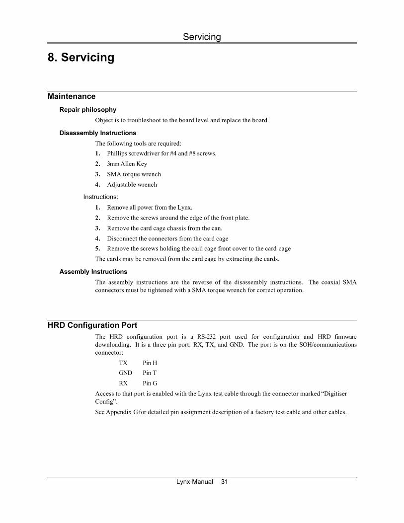
8. Servicing
Maintenance
Repair philosophy
Object is to troubleshoot to the board level and replace the board.
Disassembly Instructions
The following tools are required:
1. Phillips screwdriver for #4 and #8 screws.
2. 3mm Allen Key
3. SMA torque wrench
4. Adjustable wrench
Instructions:
1. Remove all power from the Lynx.
2. Remove the screws around the edge of the front plate.
3. Remove the card cage chassis from the can.
4. Disconnect the connectors from the card cage
5. Remove the screws holding the card cage front cover to the card cage
The cards may be removed from the card cage by extracting the cards.
Assembly Instructions
The assembly instructions are the reverse of the disassembly instructions. The coaxial SMAconnectors must be tightened with a SMA torque wrench for correct operation.
HRD Configuration PortThe HRD configuration port is a RS-232 port used for configuration and HRD firmwaredownloading. It is a three pin port: RX, TX, and GND. The port is on the SOH/communicationsconnector:
TX Pin H
GND Pin T
RX Pin G
Access to that port is enabled with the Lynx test cable through the connector marked “DigitiserConfig”.
See Appendix G for detailed pin assignment description of a factory test cable and other cables.
Lynx Manual 31
Servicing

Software & Firmware Updates
HRD24 Firmware Update Procedure
New firmware is uploaded through the factory test port. See the section above for a description ofthe factory test port. This paragraph contains the necessary instructions for uploading newfirmware. For step by step upload instructions refer to Appendix F of this manual.
1. Copy the firmware received on the update diskette to the PC's hard drive
2. Connect cable to factory test port via the communications connector.
3. Connect the cable to a PC communications port.
4. Start a PC terminal emulator program.
5. Set baud rate to 9600, 8 data bits, no parity, 1 stop bit.
6. Disable all modem handshaking options like RTS/CTS, DSR, Xon/XoffDCD detection
7. Power up the Lynx.
8. There should be a few beeps on the emulator then the text"TCP Version X.XX, compiled (date, time)Press 'M' key within 5 seconds or during memory test".
If this does not appear, then check connections and emulator settings. Note thefirmware version and date at this point.
9. Press the "M" key. A menu will appear when the memory test is complete. Thememory test takes 15 seconds to complete.
10. Press the "U" key to select the upload new firmware option.
11. From the terminal emulator, initiate an ASCII upload of the new hex file on the updatediskette.
12. The firmware is uploaded into the Lynx. This will take about 1 minute. When theupload is complete, a message "upload completed, programming flash" will appear. Afew seconds later the flash will be programmed and the Lynx will reboot. The text forthe TCP version will appear again and it should display the new firmware version anddate. At this point the firmware upload procedure is complete. The Lynx is nowready for use. If the download fails, a download error message will be displayed.You should try downloading again.
Comms Controller Firmware Update Procedure
Comms Controller firmware update can be done using Libra User Interface. For more details pleaserefer to the separate Libra User Interface manual in the Software Reference Manual of the DSSReference Manual.
NEVER power down the Lynx while it is doing a upload. This will have catastrophic results.
Lynx Manual 32
Servicing

Internal Configuration Options
Related to the seismometer input
Input Impedance
The ADC board provides space for an optional input shunt resistor which can be used to damp aseismometer. Calculate the required damping resistor value using instructions provided by theseismometer manufacturer. 'Active' seismometers such as the Guralp CMG40 should be used withno damping resistor.
The input impedance of the Lynx is normally shipped in a high impedance state (see as-shippedsheet). The user may change the input impedance to dampen the seismometer response if desired.There is one resistor required for each channel to set the impedance.
The resistor value is determined by the desired input impedance and the parallel resistance of5.0Mohms. Rset = (Rdamp * 5 * 10e6) / (5 * 10e6 - Rdamp). For most practical applications set theresistor value to the desired input impedance. Figure 9.2 shows the location of the dampingresistor for each channel. The damping resistor for channel 1 is R85, channel 2 is R86, and channel3 is R87. The resistors are located on the ADC board for channels 1-3 respectively. If the unit hassix channels then channels 4-6 can be set in exactly the same way.
Input Sensitivity
The as-shipped input sensitivity of the Lynx is shown in the as-shipped sheets. The user maychange the input sensitivity if desired. There is one resistor required for each channel to set thesensitivity.
The resistor value is determined by the following formulae:
gain = 1.275 uV/bit / desired sensitivity (uV/bit)Rgain = 2 * 10e4 / (gain x 2 -1)
The sensitivity can be increased by soldering one resistor per channel onto the ADC printed circuitboard. For example, to achieve an overall sensitivity of 192 nV per bit, each gain-setting resistorshould be set to 1.62K ohms. Figure 9.2 shows the location of the gain-setting resistor for eachchannel. The gain resistor for channel 1 is R18, channel 2 is R19, and channel 3 is R60. Theresistors to set are on the ADC board for channels 1-3 respectively. If the unit has six channelsthen channels 4-6 can be set in exactly the same way.
Note with no gain resistor installed, the gain = 0.5 and the sensitivity = 2.55 uV/bit
The input impedance should be left in the high impedance state.
3.186 nm/snone1 2550 nVCMG 40T1nm/s9.09K ohms1.6 800 nVCMG 40T
SystemSensitivity
Input Gain ResistorsInput GainInput SensitivitySeismometer
Table 2: Configuring the ADC for CMG40T active seismometer.
Configuring for an active seismometer with mass position monitoring
The first step required when connecting to an active seismometer is setting the input sensitivityand input impedance of the ADC. The input sensitivity would either be chosen to give a systemsensitivity of 1nm/s or to set the full scale levels of the seismometer and the Lynx to be the same.Connection to an active sensor (such as CMG 40T) will consist of connecting the main sensor coilto the signal inputs with the positive (+) coil connected to the positive (+) input and negative (-) tonegative (-). Connect the '+' calibration output to the motor coil '+' and the '-' calibration output to
Lynx Manual 33
Servicing

the motor coil return. The output impedance of the calibration signal is 500 ohm with a maximumcurrent of 10mA at a voltage of 5V. A series resistor is used on the calibration '+' outputs to ensurethe current is limited to this value. This is not a factor with active sensors since they buffer thecalibration signal internally.
The best performance will be found using cables built in the following manner:
The connection to each sensor should be made with a 6 pair, doubleshielded with individual internal shielding, 24 AWG (or smaller) cable.An example cable of this type would be Belden 8166. The inner shieldsof the cable should be connected only at the connector and the sensorend should be left open. The inner shield should be kept isolated fromthe outer shield. The outer shield should be connected to the chassisground and to the sensor chassis ground. If the sensor has a groundpin the connection can be done using that pin, however if there is noground connection (i.e.. SS1 sensor) then the chassis connectionshould be made by connecting to the shell of the connector with asshort a connection length as possible. A second cable should beconnected directly from the battery to the CMG40T for the powerconnection.
See the next section to configure for passive seismometer calibration with current calibration drive.
Figure 4: Position of gain and damping resistors on the ADC board.
Configuring for a passive seismometer
The first step required when connecting to a passive seismometer is setting the input sensitivityand input impedance of the ADC. The input sensitivity would normally be chosen to give a systemsensitivity of 1nm/s. The input impedance should be set to a value to give the critical dampingresistance of the seismometer.
Lynx Manual 34
Servicing

8870 ohms1.43K ohms7.49 170.1 nVMark Prod. L4C4220 ohms1.33K ohms8.02 159 nVKinemetrics SS15360 ohms3.48K ohms3.37 378 nVGeotech S13
Input ImpedanceGain ResistorsInput GainInput SensitivitySeismometer
Table 3: Configuring the ADC board for passive seismometers.
Connection to a passive sensor will consist of connecting the main sensor coil to the signal inputswith the positive (+) coil connected to the positive (+) input and negative (-) to negative (-).Connect the '+' calibration output to the motor coil '+' and the '-' calibration output to the motor coilreturn. The output impedance of the calibration signal is 500 ohm, with a maximum current of 10mAat a voltage of 5V. A series resistor is used on the calibration '+' outputs to ensure the current islimited to this value.
The best performance will be found using cables built in the following manner:
The connection to each sensor should be made with a 2 pair, doubleshielded with individual internal shielding, 24 AWG (or smaller) cable.An example of this type of cable would be Belden 8162. The innershields of the cable should be connected only at the connector and thesensor end should be left open. The inner shield should be kept isolatedfrom the outer shield. The outer shield should be connected to the chassis ground and to the sensor chassis ground. If the sensor has aground pin the connection can be done using that pin, however, if thereis no ground connection (i.e. SS1 sensor) then the chassis connectionshould be made by connecting to the shell of the connector with asshort a connection length as possible.
User Configurable Jumper Settings
Mem-Cal:
J3 1-2 Calibration Enable = +5VJ3 2-3 Calibration Enable = +12V
Factory configured jumpers
The HRD is configured using jumpers on various boards. The function of all the jumpers isexplained in the following tables. Please see the as-shipped sheets for the actual jumper settings.Note that where applicable, jumper pin 1 has a square pad. The following jumper settings are set atthe factory. These jumpers should never be changed. They are listed here for reference only. Userconfigurable jumpers are considered under the function in which the jumper is referenced.
ADC 1-3: Mem-Cal:
Jumper Setting Function Jumper Setting Function
J3 1-2 PS_SYNC J5 1-2 Voltage Calibration J6 5-6 Channel 1 Address J4 -- Not Used J7 1-2 Channel 2 Address J7 -- Not Used J8 1-2 Channel 3 Address J6 2-3 SOH1 = Mass POS 1J10-J18 2-3 Time Slot
ADC 4-6: TCP:
Jumper Setting Function Jumper Setting Function
J6 3-4 Channel 4 Address J5 1-2 USCA CLK J7 2-3 Channel 6 Address J6 1-2 USCB CLB J8 2-3 Channel 6 Address J11 1-2 Flash Program
Lynx Manual 35
Servicing

COMMS:
Jumper Setting Function Jumper Setting Function
J3A 1-2 Event_In CMOS Level J3B 5-6 Event_In CMOS Level J4A 2-3 Event_Out CMOS Level J4B 5-6 Event_Out CMOS Level J5A 2-3 RX232 J5B 5-6 CTS232 J6A 2-3 TX232 J6B -- N/A J7A -- J7B 3-4 RTS232 J7C -- J12A 1-2 AUX_CLK J12B 5-6 USCA_RI
Figure 6: Pin-out for J12, J3, J4, J5, J6
Standard seismometer configurations
Kinemetrics Ranger
Generator constant 345 volt-seconds/ metreGain set to 8.02 with 1.33K ohm gain set resistorDamping set to 4200 ohms with damping resistorConfigure for current drive with no mass position monitoringSystem sensitivity 1 nanometre per second per bit
Mark Products L4C
Generator constant 276.4 volt-seconds/ metreGain set to 7.49 with 1.43K ohm gain set resistorDamping set to 8870 ohms with damping resistorConfigure for current drive with no mass position monitoringSystem sensitivity 1 nanometre per second per bit
Geotech S13
Generator constant 629 volt-seconds/ metreGain set to 3.37 with 3.48K ohm gain set resistorDamping set to 5340 ohms with damping resistorConfigure for current drive with no mass position monitoringSystem sensitivity 1 nanometre per second per bit
Guralp CMG40T
Generator constant 800 volt-seconds/ metreGain set to 1.6 with 9.09K ohm gain set resistorDamping set to open circuit with no damping resistorConfigure for voltage drive with mass position monitoringSystem sensitivity 1 nanometre per second per bit
ORGenerator constant 800 volt-seconds/ metreGain set to nominal with no gain set resistorDamping set to open circuit with no damping resistorConfigure for voltage drive with mass position monitoring enabledSystem sensitivity 3.186 nanometres per second per bit
Lynx Manual 36
Servicing

Appendix A - Connector PinoutsTwo versions of Lynx chassis exist: RevC chassis (SSPB temperature sensor connections throughCOMMUNICATIONS connnector) and RevE chassis (with additional SSPB temperature sensorconnector). The pinouts are otherwise identical.
Figure 7: Connector Pinouts
Lynx Manual 37
Appendix A - Connector Pinouts

This page intentionally left blank.

Appendix B - Libra Data FormatIntroduction
Libra networks use a variety of data formats and protocols to support a wide range ofcommunications services. The principle protocols used are:
NMXP Used to pass data between ringbuffers
UDP Used to carry NMXP data between programs
IP Used to carry UDP packets between nodes in the network (i.e. from Lynx to NAQS).
These protocols work together. NMXP packets are encapsulated (carried) within UDP packets, andUDP packets are carried within IP packets. The beauty of this approach is that the outer IP(Internet Protocol) packet is universally recognized, and can carry the seismic data payloadthrough almost all communications media: through the Internet, through telephone lines, throughLAN (Local Area Network) networks, through almost any modern communications facility. Thisallows Nanometrics networks to easily merge with the customer's communications infrastructure.
IP
IP (Internet Protocol) packets carry data from one network node to another. The IP headeridentifies the source and destination node addresses. All remote site data (seismic, SOH, serial) isencapsulated in IP packets and these are transmitted by the satellite link to the central siteacquisition systems.
TCP and UDP
These are the most common Internet protocols: Transmission Control Protocol and User DatagramProtocol. They are used to transfer data from one software process to another. Libra networks useUDP to carry ringbuffer, SOH and authorization data. TCP is used by the Libra User Interfacesoftware to carry configuration commands to the equipment. TCP and UDP are commonlyencapsulated within IP packets, forming TCP/IP and UDP/IP.
NMXP
The Nanometrics Transfer Protocol (NMXP) is used to carry data to the NAQS acquisitionsoftware systems. This protocol is specifically designed to support acquisition: sequential packetnumbering (permitting retransmission request), identification of the oldest buffered packet(allowing remote site retransmission buffers of any size: seconds to days), and data source andformat details.
The NMXP protocol is described below. Information about Internet Protocols (TCP/IP andUDP/IP) can be found in most modern networking texts.
The NMXP packet
This data transmission format facilitates the transfer of compressed seismic data along with a widevariety of status information from an instrument to a central site. It supports error free transmissionof data using retransmission requests of bad packets. It also supports polled networks. The dataformat requires that the instrument have an accurate time source (i.e. GPS) for time tagging the dataprior to compression and transmission. The compression algorithm is based on taking the firstdifference of the data and packing the data into bytes, words, or long words . This algorithmachieves about 1.3 bytes per sample at maximum compression.
Most of the status messages can be transmitted at a user defined frequency. This allows the userto tailor ratio of data to status information. This is important on limited bandwidth or noisytransmission mediums. The status information in data format is expandable. As new status
Appendix B - Libra Data Format
Lynx Manual 39

information messages are created, they can be added to the data format without affecting theexisting information.
Lastly, the data format is simple to implement on small microprocessors. The compressionalgorithm is simple and requires little memory and processing power.
The following objectives were used in designing the data format:
1. support compressed data
2. support retransmit of packets for error correction
3. support polled networks
4. compatible with Orion
5. simple compression/decompression algorithm
6. simple to implement
7. expandable
8. programmable frequency for status information
9. not wasteful of bandwidth
Appendix B - Libra Data Format
Lynx Manual 40

Description of NMXP PacketsAll the data (seismic and status data) is gathered into sequenced and time stamped packets. Thesepackets start with a synchronization word plus an Old packet available word and finish with a CRC.The packets consist of 17 byte 'bundles' of data. Each bundle is an independent collection of data.Each packet contains a time stamp bundle followed by n data bundles where n is odd. In order toword align packets, an odd number of bundles is used. This principally benefits the TCP.
The number of bundles in a packet is a programmable parameter. The number of bundles is oddand has a range of 1-255. This allows the packet size to be tailored to the data link. The packetsize should be optimized for the data link. Short packets should be used on noisy, error prone datalinks. Packets may be the same size for the entire network, or different on each branch (a branch isconnected to one RM-4 port or one Libra remote serial port) of the network. All instruments on agiven branch must use the same packet size. Short messages must be padded out to the packetsize. Outgoing packets may have a different packet size.
In summary:
} a channel is a unique stream of information
} an instrument may transmit 1 or more channels of information
} a packet contains information from only one channel
} a packet is a uniquely identifiable collection of information that is transmitted
} packets are a configurable fixed size
} a branch connects 1 or more instruments to one port on the RM-4
} “outgoing” is the direction from the central site to remote site, “incoming” is theopposite
} all instruments on a branch use the same incoming packet size
} all instruments on a branch use the same outgoing packet size
} outgoing packets do not have the Oldest packet word
} incoming packets contain data, status, or configuration information
} outgoing packets contain retransmit requests, or configurations
} all data is represented in the little endian format (intel format)
Appendix B - Libra Data Format
Lynx Manual 41

CRC for the PacketsFor simplicity CRCs should be an addressable data size, i.e. 8, 16 or 32 bits. Sending 32 bits (4bytes) is too much overhead, 8 bits is not sufficient. Therefore select 16 bits as the CRC size.
There are 2 good common standard 16 bits polynomials, the CRC-16 and the 16 bit CRC-CCITT.The reversal of these polynomials are also known to be good and are also used. The digitiser usesthe 16 bit CRC-CCITT. Therefore select the 16 bit CRC-CCITT as the CRC polynomial.
On the bit level CRCs can be calculated from either end. Normally CRCs are calculated mostsignificant bit first, i.e. the byte 0xD5 is done 11010101. Reflected CRCs are calculated leastsignificant bit first, i.e. the byte 0xD5 is done 10101011. Bits of a byte are transmitted over a seriallink least significant bit first. Most CRCs calculated for transmission over a serial link are doneleast significant bit first. The digitiser uses a reflected CRC algorithm. Therefore, select a reflectedCRC algorithm to be used.
If the accumulated CRC value is 0, it is unaffected by the 0 byte and errors may not be detected.The CRC should not be initialized to 0 if messages contain leading 0s may occur. Since the receiversyncs on a non-zero sync word, this is not a problem if these bytes are included. The digitiser uses0xFFFF as its initial value for the CRC. Therefore, select 0 as the initial value for the CRC.
If the CRC is sent as is, the accumulated CRC value afterwards is then 0. This can pose problems ifmessages have the CRC and trailing 0s; see above. Modifying the CRC before transmitting it haslittle to gain and complicates matters. The Orion XORs the CRC with 0xFFFF before transmitting itand checks for 0xF0B8 on receive. Therefore, select transmitting the CRC as is.
#define CrcUpdate(usCrc,ubByte) \ ((usCrc) >> 8) ^ ausCrcTable [((usCrc) &0xff) ^ (ubByte)]SendByte (ubByte){ usCrc = CrcUpdate (usCrc,ubByte); UscTx = ubByte ^ ubScramble;}RecvByte (){
ubByte = UscRx ^ ubScramble;usCrc = CrcUpdate (usCrc, ubByte);return ubByte;
}SendMsg (pubData){ usCrc = 0;
SendByte (ubSync1); SendByte (ubSync2); SendLong (ulOldestSequenceNumber); for (us = 0; us < usNumberMsgByte, us ++)
SendByte (pubData [us]); usCrc2 = usCrc; SendWord (usCrc2);}
RecvMsg (pubData){
while (1){
while (1){
Appendix B - Libra Data Format
Lynx Manual 42

while (1){
usCrc = 0; if (RecvByte() == ubSync1)
break;}if (RecvByte () == ubSync2)
break;}ulOldestSequenceNumber = RecvLong ();for (us = 0; us < usNumberMsgByte, us ++)
pubData [us] = RecvByte ();usCrc2 = usCrc;if (usCrc2 == RecvWord () && usCrc == 0)
break;}
}
unsigned short ausCrcTable[256] ={ 0x0000, 0x1189, 0x2312, 0x329B, 0x4624, 0x57AD, 0x6536, 0x74BF, 0x8C48,0x9DC1, 0xAF5A, 0xBED3, 0xCA6C, 0xDBE5, 0xE97E, 0xF8F7, 0x1081, 0x0108, 0x3393,0x221A, 0x56A5, 0x472C, 0x75B7, 0x643E, 0x9CC9, 0x8D40, 0xBFDB, 0xAE52, 0xDAED,0xCB64, 0xF9FF, 0xE876, 0x2102, 0x308B, 0x0210, 0x1399, 0x6726, 0x76AF, 0x4434,0x55BD, 0xAD4A, 0xBCC3, 0x8E58, 0x9FD1, 0xEB6E, 0xFAE7, 0xC87C, 0xD9F5, 0x3183,0x200A, 0x1291, 0x0318, 0x77A7, 0x662E, 0x54B5, 0x453C, 0xBDCB, 0xAC42, 0x9ED9,0x8F50, 0xFBEF, 0xEA66, 0xD8FD, 0xC974, 0x4204, 0x538D, 0x6116, 0x709F, 0x0420,0x15A9, 0x2732, 0x36BB, 0xCE4C, 0xDFC5, 0xED5E, 0xFCD7, 0x8868, 0x99E1, 0xAB7A,0xBAF3, 0x5285, 0x430C, 0x7197, 0x601E, 0x14A1, 0x0528, 0x37B3, 0x263A, 0xDECD,0xCF44, 0xFDDF, 0xEC56, 0x98E9, 0x8960, 0xBBFB, 0xAA72, 0x6306, 0x728F, 0x4014,0x519D, 0x2522, 0x34AB, 0x0630, 0x17B9, 0xEF4E, 0xFEC7, 0xCC5C, 0xDDD5, 0xA96A,0xB8E3, 0x8A78, 0x9BF1, 0x7387, 0x620E, 0x5095, 0x411C, 0x35A3, 0x242A, 0x16B1,0x0738, 0xFFCF, 0xEE46, 0xDCDD, 0xCD54, 0xB9EB, 0xA862, 0x9AF9, 0x8B70, 0x8408,0x9581, 0xA71A, 0xB693, 0xC22C, 0xD3A5, 0xE13E, 0xF0B7, 0x0840, 0x19C9, 0x2B52,0x3ADB, 0x4E64, 0x5FED, 0x6D76, 0x7CFF, 0x9489, 0x8500, 0xB79B, 0xA612, 0xD2AD,0xC324, 0xF1BF, 0xE036, 0x18C1, 0x0948, 0x3BD3, 0x2A5A, 0x5EE5, 0x4F6C, 0x7DF7,0x6C7E, 0xA50A, 0xB483, 0x8618, 0x9791, 0xE32E, 0xF2A7, 0xC03C, 0xD1B5, 0x2942,0x38CB, 0x0A50, 0x1BD9, 0x6F66, 0x7EEF, 0x4C74, 0x5DFD, 0xB58B, 0xA402, 0x9699,0x8710, 0xF3AF, 0xE226, 0xD0BD, 0xC134, 0x39C3, 0x284A, 0x1AD1, 0x0B58, 0x7FE7,0x6E6E, 0x5CF5, 0x4D7C, 0xC60C, 0xD785, 0xE51E, 0xF497, 0x8028, 0x91A1, 0xA33A,0xB2B3,
Appendix B - Libra Data Format
Lynx Manual 43

0x4A44, 0x5BCD, 0x6956, 0x78DF, 0x0C60, 0x1DE9, 0x2F72, 0x3EFB, 0xD68D,0xC704, 0xF59F, 0xE416, 0x90A9, 0x8120, 0xB3BB, 0xA232, 0x5AC5, 0x4B4C, 0x79D7,0x685E, 0x1CE1, 0x0D68, 0x3FF3, 0x2E7A, 0xE70E, 0xF687, 0xC41C, 0xD595, 0xA12A,0xB0A3, 0x8238, 0x93B1, 0x6B46, 0x7ACF, 0x4854, 0x59DD, 0x2D62, 0x3CEB, 0x0E70,0x1FF9, 0xF78F, 0xE606, 0xD49D, 0xC514, 0xB1AB, 0xA022, 0x92B9, 0x8330, 0x7BC7,0x6A4E, 0x58D5, 0x495C, 0x3DE3, 0x2C6A, 0x1EF1, 0x0F78};
Appendix B - Libra Data Format
Lynx Manual 44

Outgoing PacketsAll outgoing packets are a fixed size of 30 bytes. There are no retransmit requests from thedestination for outgoing packets.
The basic format is as follows:
2 bytes Synchronization Word = AA BB2 bytes Instrument ID (5 bits model type, 11 bits serial number)4 bytes Long Seconds1 byte Packet Type3 bytes Packet Information Header4 x 4 bytes Data Section2 bytes Packet CRC
Retransmission Request by Sequence Number Packet
1 byte Packet type = 11 byte Channel2 bytes Spare4 bytes Sequence number 1 requested4 bytes Sequence number 2 requested4 bytes Sequence number 3 requested4 bytes Sequence number 4 requested
Retransmission Request by Sequence Number Range Packet
1 byte Packet type = 21 byte Channel2 bytes Spare4 bytes First sequence number requested4 bytes Last sequence number requested8 byte Spare
digitiser Calibration Packet
1 byte Packet Type = 61 byte Channel Mask (ch 1, 2, 3, 4 = 1, 2, 4, 8)2 bytes Spare4 bytes us-int32 Start Time (long seconds)4 bytes float Frequency in Hz (0.01 <= freq < sample rate / 2)4 bytes float Amplitude in Volts (0 < amp <= 5.0)2 bytes us-int32 Duration in seconds (0 < duration <= 3600)
Appendix B - Libra Data Format
Lynx Manual 45

Incoming PacketsAll incoming packets consist of a synchronization pattern, oldest packet available for a data stream,time stamp bundle, n other bundles, and a CRC:
2 bytes Synchronization Word4 bytes Oldest Packet Available for a Data Stream17 bytes Packet Header Bundle17 * n bytes n bundles where n is odd2 bytes Packet CRC
Compressed Data Packet
A data packet always consists of a time stamp bundle followed by n data bundles (where n is userdefined). A time stamp bundle contains a sequence number, the time of the first sample, instrumentID (model and serial number), sample rate of packet and channel number, and the first sample.
Compressed Data Packet Header Bundle
1 byte Packet type = 1 ( bit 5 = 1 is for retransmit)4 bytes Long seconds2 bytes Sub-seconds in 10,000th of a second2 bytes Instrument ID [5 bit model type, 11 bit serial number]4 bytes Sequence Number1 byte Sample Rate, Channel # [5 bits for sample rate, 3 bits for channel #]3 bytes X0 (first sample)
The instrument ID defines the instrument type transmitting the channel of data. Currently thefollowing instrument IDs are defined:
0 HRD1 Orion2 RM33 RM44 Lynx5 Cygnus6 Callisto7 Carina8-31 Reserved for future use
The sample rate is an enumerated value. The table below defines the different sample rates:
reserved for future use17-31200 s/s1120 s/s5120 s/s16125 s/s1010 s/s425 s/s15100 s/s95 s/s31000 s/s1480 s/s82 s/s2500 s/s1350 s/s71 s/s1250 s/s1240 s/s6reserved0
Data Bundle
A data bundle contains between 4 and 16 compressed samples of data. The samples arecompressed using a first difference algorithm. The data is compressed as byte, word, or longdifferences. Each set of four bytes contains either 4 byte differences, 2 word differences, or 1 long
Appendix B - Libra Data Format
Lynx Manual 46

difference. The compression bits indicate how each set of 4 bytes is packed. For each 4 byte setthere are 2 compression bits. The compression bits are packed into a byte as follows:
byte : ww xx yy zz where the compression bits indicate:ww- data set 1 00 not usedxx- data set 2 01 byte differenceyy- data set 3 10 word differencezz- data set 4 11 long difference
The format of the data bundle is as follows:
1 byte Compression Bits4 bytes Compressed data set 14 bytes Compressed data set 24 bytes Compressed data set 34 bytes Compressed data set 4
Null Bundle
This bundle is provided to pad out packets. The first occurrence of a Null bundle indicates thatthere is no further data in the packet. The null bundle contains no useful information. The receivershould disregard this bundle and all remaining bundles, and skip to the next packet.
1 byte Bundle Type = 916 bytes Filler
Filler Packet
A filler packet is required for radio links. Non-zero data must always be transmitted by radios. Toaccomplish this the instruments transmit filler packets whenever there is no data to transmit.Repeaters discard received filler packets and generate their own filler packets for transmission.This method is required because a repeater can also multiplex.
The only valid data in a filler packet is the bundle type. The rest of the packet is filled a value thatis good for radio transmission (to be defined)
Filler Packet Header Bundle
1 byte Packet type = 9 ( bit 5 = 1 is for retransmit)16 bytes defined as filler characters
Note : scrambler default is 0xA5
The following is a graphical illustration of an incoming data stream, containing only data packetsand filler packets. An actual data stream will also have state-of-health packets.
Appendix B - Libra Data Format
Lynx Manual 47

D a) Compressed Data PacketStart Data Stop
(MSB) 7 6 5 4 3 2 1 0 (LSB)
1 Byte = 10 bits: 1 2 3 4 5 6 7 8 9 10
1 2 3 4 5 6 ...0000 0001 (Packet first time)
0010 0001 (Packet retransmitted) Sync Word Oldest packet in HRD mem.
... 1 2 3 4 5 6 7 8 9 10 11 12 13 14 15 16 17 ...
Packet Long seconds Subseconds I D Sequence # s/s First sample valuetype (1/10,000s) (5 bit=model ch # (others are
11 bit=S/N) differences)
Compressed Data Packet Header Bundle
Bits Describe Each data set can represent: Compression bits indicate:Data Set *4 samples (byte differences) 00 not used
76 1 *2 samples (word differences) 01 byte difference54 2 *1 sample (long difference) 10 word difference32 3 11 long difference10 4
... 1 2 3 4 5 6 7 8 9 10 11 12 13 14 15 16 17 ...
Compre Data Set 1 Data Set 2 Data Set 3 Data Set 4ssionbits
Data Bundle (1)
... 1 2 3 4 5 6 7 8 9 10 11 12 13 14 15 16 17 ...
Compre Data Set 1 Data Set 2 Data Set 3 Data Set 4ssionbits
Data Bundle (2)
(1-255 data bundles per packet, user configurable; good number is 15)
... 1 2 3 4 5 6 7 8 9 10 11 12 13 14 15 16 17 ...
Compre Data Set 1 Data Set 2 Data Set 3 Data Set 4ssionbits
Data Bundle (15)
... 1 2
CRC
Appendix B - Libra Data Format
Lynx Manual 48

F b) Filler Packet
1 2 3 4 5 6 ...0000 0000
0000 1001 (Packet first time) scrambled to Sync Word Not used
0010 1001 (Packet retransmitted) 1010 0101 (0xA5)
... 1 2 3 4 5 6 7 8 9 10 11 12 13 14 15 16 17 ...
Packet 16xfillertype
Filler Packet Header Bundle
... 1 2 3 4 5 6 7 8 9 10 11 12 13 14 15 16 17 ...
17 x Filler (1)
...
...
... 1 2 3 4 5 6 7 8 9 10 11 12 13 14 15 16 17 ...
17 x Filler (15)
... 1 2
CRC
Bandwith Estimate Example
1 ch 16 samples/bundle x 15 bundles = 240 samples/packet100 s/s (takes 240/100=2.4 s to digitize a packet)9600 baud15 bundles/packet (6+17+15x17+2)x10=2800 bits/packetsignal always quiet (byte difference) 1/9600 s/bit => 2800/9600 = 0.2916666 s/packet
bandwith is used only 0.291666/2.4=0.1215=12.15%minimum needed baud rate is 9600*0.1215=1166.66 baudwith Sync abd Status packets => cca 1200 baud
2.4 s 2.4 s0.3 s 0.3 s
... F D F F F F F F F D F F F F F F F D ...
Appendix B - Libra Data Format
Lynx Manual 49

Status PacketA status packet consists of a status time stamp bundle followed by n status bundles. A statustime stamp consists of a sequence number, the time (nominal time when the packet was created),instrument ID (model and serial number).
Status bundles have a general format that is outlined below:
1 byte bundle type = xx4 bytes Long seconds12 bytes Defined by the specific bundle typeor
1 byte bundle type = xx16 bytes Defined by the specific bundle type
State-of-Health Packet Header Bundle
1 byte Packet type = 2 (bit 5 = 1 is for retransmit)4 bytes Long seconds 2 bytes Sub-seconds in 10,000th of a second, this value always 02 bytes Instrument ID [5 bit model type, 11 bit serial number]4 bytes Sequence Number4 bytes Reserved for future use
The instrument ID defines the instrument type transmitting the channel of data. Currently thefollowing instrument IDs are defined:
0 HRD1 Orion2 RM33 RM44 Lynx5 Cygnus6 Callisto7 Carina8-31 Reserved for future use
Fast External State-Of-Health Bundle
1 byte bundle type = 32 4 bytes long seconds4 bytes float of calibrated fast SOH1 in volts or units4 bytes float of calibrated fast SOH2 in volts or units4 bytes float of calibrated fast SOH3 in volts or units
Slow External State-Of-Health Bundle
1 byte bundle type = 334 bytes long seconds4 bytes float of calibrated slow SOH1 in volts or units4 bytes float of calibrated slow SOH2 in volts or units4 bytes float of calibrated slow SOH3 in volts or units
Digitiser Slow Internal SOH Bundle
1 byte bundle type = 34
Appendix B - Libra Data Format
Lynx Manual 50

4 bytes long seconds4 bytes float of battery voltage measured at PSU in volts4 bytes float of VCXO temperature in degrees Celsius4 bytes float of radio SNR in xxxx
GPS Time Quality Bundle
1 byte bundle type = 394 bytes long seconds2 bytes GPS on time2 bytes GPS off time during the last cycle2 bytes GPS time to lock in seconds2 bytes Time difference at lock in counts (divide by 3.84 to get microseconds)2 bytes VCXO offset (div. by 16 to get the DAC offset)1 byte Reason GPS turned off:
0 -PLL finished correcting time error1 -GPS on time expired
1 byte Final GPS mode:0 -3D navigation1 -2D navigation2 -tracking 1 sat or more3 -searching for satellites
VCXO Calibration Bundle
1 byte Bundle type = 74 bytes Long seconds2 bytes VCXO value2 bytes Time difference at lock in counts (divide by 3.84 to get microseconds)2 bytes Time Error (in counts)2 bytes Frequency Error (in counts/sec or counts/ 16 secs)2 bytes Crystal temperature1 byte PLL Status?( 1=fine locked, 2=coarse locking, 3 =temp. ref, gps off, 4=temp
ref, gps on)1 byte GPS Status(0=3D, 1=2D, 2=1 sat, 3=search, 4= gps off, 5-6=gps error)
Null Bundle
This bundle is provided to pad out packets. The first occurrence of a Null bundle indicates thatthere is no further data in the packet. The null bundle contains no useful information. The receivershould disregard this bundle and may skip to the next packet.
1 byte Bundle Type = 916 bytes Filler
Min-Max1 Bundle
The activity indicator provides a 1 Hz or slower filtered summary of a seismic data channel. Thiswould be used to provide the end user with a summary of the collected data. This allows the userto quickly browse large quantities of data for events. The data may be filtered using a 5th orderfilter. The filter may be low pass, high pass, or band pass. In order not to lose the higherfrequency information, the minimum and maximum over the interval of the filtered signal is stored. The interval is a programmable value of 1s or greater.
1 byte Bundle type = 104 bytes Long seconds 3 bytes Filtered min. over 1st interval3 bytes Filtered max. over 1st interval3 bytes Filtered min. over 2nd interval3 bytes Filtered max. over 2nd interval
Appendix B - Libra Data Format
Lynx Manual 51

Min-Max2 Bundle
The activity indicator provides a 1 Hz or slower filtered summary of a seismic data channel. Thiswould be used to provide the end user with a summary of the collected data. This allows the userto quickly browse large quantities of data for events. The data may be filtered using a 5th orderfilter. The filter may be low pass, high pass, or band pass. In order not to lose the higherfrequency information, the minimum and maximum over the interval of the filtered signal is stored. The interval is a programmable value of 1s or greater.
1 byte Bundle type = 114 bytes Long seconds 3 bytes Filtered min. over 1st interval3 bytes Filtered max. over 1st interval3 bytes Filtered min. over 2nd interval3 bytes Filtered max. over 2nd interval
Instrument Log Bundle
Any errors or warnings generated by the instrument are stored in this bundle. Some typical errorsor warnings are GPS locked/unlocked, low battery, clock adjustments, external events, self testerrors, status of disk space, duty cycle, etc.
1 byte Bundle type = 124 bytes Long seconds2 bytes Error code , where bits 0-11= error code, bits 12-15 = data format, 2 bytes Error Level8 bytes Error Parameters
Error Level is a bit mapped value which is broken down as follows:
bits 0-7 Area (each bit identifies a separate area)- currently unusedbits 8-10 Processor (TCP, Aux, DSP)bits 11-15 Error Level (Fatal, error, warning, info, debug
GPS Location Bundle
This bundle contains the latitude and longitude of the instrument's GPS antenna. This bundle hasa programmable measurement frequency. The latitude and longitude is stored in an extendedfloating point format.
1 byte Bundle type = 134 bytes Long seconds4 bytes Latitude4 bytes Longitude4 bytes Elevation
GPS Satellite Status/Reference Time Error Bundle
This bundle contains the status of the GPS engine's satellite tracking channels. It records thesignal to noise ratio, activity, and satellite number for the five satellite tracking channels. Theactivity indicates whether the GPS channel is idle, searching or locked to a satellite signal. Thisinformation is very useful in diagnosing a GPS engine that is not locking.
1 byte Bundle type = 154 bytes Long seconds2 bytes Status bits (see Rockwell manual, contains operating mode, figure of merit)10 bytes GPS Satellite Channel - 2bytes per channel
where the 2 bytes are defined:bits 0-4 Satellite PRN code (0-31)bits 5-7 Unusedbits 8-13 Signal to Noise Ratio (0-63)
Appendix B - Libra Data Format
Lynx Manual 52

bits 14-15 Activity 0=idle, 1 searching, 3=tracking
D1 (Early) Threshold Trigger Bundle
The D1 threshold trigger bundle reports the start of a threshold trigger event. It is sent at aprogrammable time after the start of a trigger. It reports the start time of the trigger, along withsome statistics about the trigger. The D1 trigger bundle is followed by a D2 trigger which reportsthe end of a trigger. The D1 bundle contains the peak amplitude, the half period of the amplitude,and the samples after trigger of the peak amplitude.
1 byte Bundle type = 204 bytes Long seconds2 bytes Sub-seconds in 10,000th of a second2 bytes LTA value (low word of LTA which is a long, hi word in D2)2 bytes Half period of peak amplitude2 bytes Samples after trigger of peak amplitude1 byte Channel# (3 bits) | trigger # (5 bits)3 bytes Peak amplitude
D2 (Late) Threshold Trigger Bundle
The D2 threshold trigger bundle reports the end of a threshold trigger event. It is sent at aprogrammable time after a trigger is finished. It reports the end time of the trigger, along with somestatistics about the trigger. The D2 bundle contains the peak amplitude, the half period of theamplitude, and the samples after trigger of the peak amplitude for the entire trigger event.
1 byte Bundle type = 214 bytes Long seconds2 bytes Sub-seconds in 10,000th of a second2 bytes LTA value (hi word of LTA which is a long, low word in D1)2 bytes Half period of peak amplitude2 bytes Samples after trigger of peak amplitude1 byte Channel# (3 bits) | trigger # (5 bits)3 bytes Peak amplitude
D1 (Early) STA/LTA Trigger Bundle
The D1 STA/LTA trigger bundle reports the start of a STA/LTA trigger event. It is sent at aprogrammable time after the start of a trigger. It reports the start time of the trigger, along withsome statistics about the trigger. The D1 trigger bundle is followed by a D2 trigger which reportsthe end of a trigger. The D1 bundle contains the peak amplitude, the half period of the amplitude,and the samples after trigger of the peak amplitude.
1 byte Bundle type = 224 bytes Long seconds2 bytes Sub-seconds in 10,000th of a second2 bytes LTA value (low word of LTA which is a long, hi word in D2)2 bytes Half period of peak amplitude2 bytes Samples after trigger of peak amplitude1 byte Channel# (3 bits) | trigger # (5 bits)3 bytes Peak amplitude
D2 (Late) STA/LTA Trigger Bundle
The D2 STA/LTA trigger bundle reports the end of a STA/LTA trigger event. It is sent at aprogrammable time after a trigger is finished. It reports the end time of the trigger, along with somestatistics about the trigger. The D2 bundle contains the peak amplitude, the half period of theamplitude, and the samples after trigger of the peak amplitude for the entire trigger event.
1 byte Bundle type = 234 bytes Long seconds
Appendix B - Libra Data Format
Lynx Manual 53

2 bytes Sub-seconds in 10,000th of a second2 bytes LTA value (hi word of LTA which is a long, low word in D1)2 bytes Half period of peak amplitude2 bytes Samples after trigger of peak amplitude1 byte Channel# (3 bits) | trigger # (5 bits)3 bytes Peak amplitude
Event Bundle
1 byte Bundle type = 244 bytes Long Seconds4 bytes End Time in Long seconds1 byte Cause (1=external, 2=internal, 4=manual (calibration))1 byte Trigger Flags (1 bit per trigger, LSB = trigger 0)6 byte Spare
Appendix B - Libra Data Format
Lynx Manual 54

Appendix C - Instrument Log MessagesThe Lynx instrument log provides a record of the normal ongoing operation of the instrument, aswell as specific incidents which may affect data quality or timing. The Lynx generates 5 differentcategories of message:
Information Document the normal operation of the Lynx.Warnings Minor incidents which may slightly affect data quality or timing.Errors Incidents which may result in significant loss of data.Fatal Errors Serious malfunctions of the Lynx.Debug Info Verbose trace messages.
This is a complete list of the messages generated by the Lynx digitiser. Some of the messages inthis list are relevant only to a Lynx digitiser running in Orion mode. All the messages that referencethe "AUX" should never occur while running in Lynx mode.
Informational Messages
Message 1039: DSP diag RC=r cnt=n.
The DSP diagnostics returned the value r on the nth time run. This is aninformational message if r is 0 and a warning message otherwise.
Message 1041: TCP turn LEDs on.
The TCP turned on the LEDs after detecting a user button press.
Message 1042: TCP turn LEDs off.
The TCP turned off the LEDs after powering off the AUX or after 5 minutesof no user activity.
Message 1054: Recording Started.
Data recording has started as requested by the AUX.
Message 1055: Recording stopped.
Data recording has stopped as requested by the AUX.
Message 1056: Window started ssss-eeee.
The recording window from time ssss to time eeee has started.
Message 1057: Window ended ssss-eeee.
The recording window from time ssss to time eeee has ended.
Message 1060: Pll fine locked.
The TCP is phase locked. It is using the average of several seconds of GPSmessages. The absolute time error is less than 10 microseconds.
Message 1061: Pll coarse locking.
The TCP is phase locking, skewing the time to the correct.
Message 1068: GPS lost navigation.
The GPS engine is not able to generate a navigation solution using thesatellites in view.
Message 1069: GPS gain navigation.
The GPS engine is now able to generate a navigation solution using thesatellites it is tracking.
Message 1070: User button pressed.
The TCP detected a user button press. The next message indicates theaction taken which is turning on the LEDs or powering on the AUX.
Lynx Manual 55
Appendix C - Instrument Log Messages

Message 1072: GPS power on.
The TCP powered the GPS on so that it can correct its internal time.
Message 1073: GPS power off.
The TCP powered the GPS off after it had corrected its time to within 1microsecond or after the maximum on time had elapsed.
Message 1075: Disk heater on, dd seconds, tt C.
The TCP powered the disk heater on to warm it up in preparation of startingthe AUX processor. There are dd seconds of memory left and the currentdisk temperature is tt degrees Celsius.
Message 1076: Disk heater off, dd seconds, tt C.
The TCP powered the disk heater off after warming it up in preparation ofstarting the AUX processor. There are dd seconds of memory left and thecurrent disk temperature is tt degrees Celsius.
Message 1079: Disk temperature tt C.
The temperature of the disk cartridge has passed one of the safety limits to ttdegrees Celsius. If the disk is too hot or too cold the AUX processor maynot work correctly. The disk may be heated to within temperaturespecifications or these limits may be disregarded.
Message 1080: GPS engine state sssss.
The GPS engine state has changed to sssss, which is one of the following:
Search The GPS engine is searching for satellites.Track The GPS engine is tracking at least one satellite.2D Nav The GPS engine is navigating in 2D, constant altitude.3D Nav The GPS engine is navigating in 3D.
Warning Messages
Message 1024: TCP version m.nn.
The TCP startup message with version number m.nn.
Message 1025: Clock zap sss, mmm
The internal time of TCP has changed by sss seconds and mmmmilliseconds. A discontinuity in data timing will result.
Message 1026: TCP rx msg=mmm, st=xx.
The TCP received the unexpected message mmm from the AUX while instate xx.
Message 1039: DSP diag RC=r cnt=n.
The DSP diagnostics returned the value r on the nth time run. This is aninformational message if r is 0 and a warning message otherwise.
Message 1043: GPS error, ssss.
The TCP detected an error in the reception of messages from the GPS. Theerror ssss is one of the following:
Missing No GPS was detected at startup.Overrun A byte was not received in time.Frame A byte was received with an invalid stop bit.Parity A byte was received with an invalid parity bit.InvSync A message header had an incorrect sync word.HdrCs A message header had an incorrect checksum.DataSize A data message had an invalid length.
Lynx Manual 56
Appendix C - Instrument Log Messages

DataCs A data message had an incorrect checksum.BufFull The GPS message buffer was full.
Message 1044: GPS lost lock.
The GPS has lost lock; its time is unreliable. The TCP is no longer using theGPS for phase locking its time.
Message 1045: GPS gain lock.
The GPS has gained lock; its time is now valid. The TCP is once again usingthe GPS for phase locking its time.
Message 1046: GPS online.
Messages are now being received from the GPS.
Message 1047: GPS offline, rebooting.
The TCP has not received a valid message from the GPS in over 10 s. Powerto the GPS is turned off immediately and back on in 10 s.
Message 1049: TCP rx err len=nnn, xxxx
The TCP received an invalid message from the aux of length nnn. The statusword from the serial port was xxxx.
Message 1050: Inv msg len exp nnn got mmm.
The TCP received an invalid message length from the aux. The message saidit was nnn bytes; instead it received mmm bytes.
Message 1052: Config saved ok.
The configuration was saved successfully. The TCP is now rebooting touse the new configuration.
Message 1062: Battery voltage, nn.nn.
The input voltage has changed over a battery voltage threshold value. Thecurrent voltage reading is nn.nn volts.
Message 1066: Rx invalid config
The TCP received an invalid configuration from the AUX. The TCP isignoring it and continuing to run with its current configuration.
Message 1071: PLL did not fine lock.
The GPS was on for its maximum allowed duration before it could correct itstime error to within 1 microsecond. The GPS is being turned off anyway.
Message 1074 Using xxxx power source.
The Orion switched the source of its input voltage. The Orion will use themains/charger power supply if present, otherwise it will use the externalbattery if it has not been discharged, in which case it will use the internalbatteries.
Message 1077 Disk removed.
The Orion has detected that the disk cartridge has been removed. The AUXprocessor will not be booted until after it has been inserted. If it is notinserted before running out of memory, data will be lost.
Message 1078 Disk inserted.
The Orion has detected that the disk cartridge has been inserted.
Message 1081: GPS time error sss, mmm.
The GPS is reporting the digitiser time is incorrect by sss seconds and mmmmilliseconds. This error must remain stable for some time before the digitiser
Lynx Manual 57
Appendix C - Instrument Log Messages

will accept it as correct. If the time error is 0, this indicates that the GPS is nolonger indicating that the digitiser time is incorrect.
Message 1082: Digitiser time valid.
The digitiser time is now accepted as correct and the GPS must indicate thesame error for a prolonged period for it to be accepted. Any large errors inthe GPS time are corrected by resetting the GPS engine.
Message 1083: Digitiser time invalid.
The GPS engine has repeatedly indicated that the digitiser time is wrong sothe digitiser will believe it and proceed as on startup.
Message 1085: Charger mode mmmm.
The internal disk charger is now on either a slow charge or off, indicated bymmmm.
Error Messages
Message 1034: DSP send cmd not ready.
The TCP tried to send a command to the DSP but it was not ready to receiveone. The TCP will restart the DSP to ensure proper acquisition.
Message 1035: DSP send cmd failed.
The TCP sent a command to the DSP which it did not acknowledge ascompleted. The TCP will restart the DSP to ensure proper acquisition.
Message 1036: DSP send word not ready.
The TCP tried to send a word to the DSP but it was not ready to receive one.The TCP will restart the DSP to ensure proper acquisition.
Message 1037: DSP send word failed.
The TCP sent a word to the DSP which it did not acknowledge as received.The TCP will restart the DSP to ensure proper acquisition.
Message 1038: DSP read word not ready.
The TCP tried to read a word from the DSP but it was not ready to send one.The TCP will restart the DSP to ensure proper acquisition.
Message 1040: DSP startup failure.
The TCP failed to download the runtime code to the DSP.
Message 1053: Config failed to save.
The configuration failed to save. The TCP is continuing to run with itscurrent configuration.
Message 1065: Mem bank invalid m of n
A memory check detected an error in memory bank m. The memory wasconfigured to use n memory banks.
Message 1067: DSP invalid bundle xxxx.
The TCP received an invalid bundle from the DSP. The TCP is ignoring thisbundle and is allowing the DSP to continue to digitise.
Fatal Error Messages
Message 1029: TCP: AUX time out.
The AUX is not communicating with the TCP. This results in the TCPcycling power to the AUX. If the communications problem repeats, the TCPwill also reboot itself.
Lynx Manual 58
Appendix C - Instrument Log Messages

Message 1048: DSP time out, restarting
The DSP has not sent a valid message to the TCP in over 2 s. The DSP willbe restarted.
Message 1051: Mem corrupt in ffff.
A memory buffer corruption was detected in function ffff. The TCP isrebooting.
Message 1059: Mem pointer invalid, xxxxxx.
The TCP detected the invalid pointer xxxxxx in the memory buffer.
Message 1084: Main loop stopped, rebooting.
The TCP detected that the main processing loop is no longer running. It isrebooting to recover.
The TCP may also report any message as a Fatal Message if on startup it finds an invalid memorybuffer but a valid message. This message is sent as a Fatal Message to possibly help explain whyit rebooted.
Verbose Trace (Debug) Messages
Message 1058: TCP got AUX msg xxx.
The TCP received the message xxx from the AUX.
Message 1063: Event started n trigs, m.
The event detector has declared the start of an event with n triggers; m is abitmask indicating which triggers were on at the time.
Message 1064: Event ended n trigs, m.
The event detector has declared the end of an event with n triggers; m is abitmask indicating which triggers were on at the time.
Lynx Manual 59
Appendix C - Instrument Log Messages

This page intentionally left blank.

Appendix D - Filter Response Plots, Poles & Zeroes
ResponseAnalog signals connected to the Lynx are low pass filtered using a three stage anti-alias filterbefore being sampled at 240 kHz. This data is later low pass filtered and decimated using a 3 to 5stage FIR filter to give the output sample rate. Depending on the requested sample rate differentfilters are used and different number of filter stages are required. The output bandwidth will alwaysbe 0.4 x F sample out.
The low frequency response is also configurable using the DC removal IIR filter. With no filter theresponse is to DC. With the DC removal filter enabled it can be set to a number of predeterminedfrequencies depending on the customers' application.
System Filter Values
Transfer Functions
The transfer functions of all the components in the Lynx are as follows:
Analog Low Pass Anti-alias Filter
5th order Bessel Low-pass
F(s) = z1
2z22z3
(s2 +sz1Q1
+ z1 2)(s2 +sz 2Q2
+ z2 2)(s + z3)
Note: 1. Damping and Q are related by the expression D = 1/2Q2. The complex frequency response is obtained by substituting s=-jz
Digital FIR Low-pass
N-1y(n) = c(i) *x(n-i)S
i=0
Optional Digital IIR High-pass.
y(n) = K % [x(n) − x(n − 1)] + F1 % y(n − 1)
Digital Response (Time Domain Difference Equations)
} x(n) is current sample
} x(n-1) is previous sample, etc.
} y(n) is the output sample
} y(n-1) is the previous output sample
} c(i) is a FIR coefficient
} N is the number of coefficients
} K is the filter gain (see coefficients for calculation of value)
} F is the filter coefficient (see coefficients for calculation of value)1
Lynx Manual 61
Appendix D - Filter Response Plots, Poles & Zeroes

Coefficients
The values for all the coefficients for these transfer functions and for the different sample rates are:
5th Order Bessel Analog Low-pass Filter
= 1500Hzf3db
= 14713z1 = 16594z2 = 14202z3= 0.916478Q1= 0.563536Q2
Zeros None
Poles -2077.65 1080.15-2077.65 -1080.15-1440.9 2213.4-1440.9 -2213.4-2260.35 0.0
Lynx Manual 62
Appendix D - Filter Response Plots, Poles & Zeroes

Digital FIR Filters
The individual digital filter stages and associated decimation for each output sample rate isindicated below:
2 3 5 Decimation118 30 34 # of Coefficients1000 3 2 1 Coefficient set
2 2 3 5 Decimation 118 118 30 34 # of Coefficients500 3 3 2 1 Coefficient set4 2 3 5 Decimation
256 118 30 34 # of Coefficients250 9 3 2 1 Coefficient set5 2 3 5 Decimation
256 118 30 34 # of Coefficients200 10 3 2 1 Coefficient set
2 2 4 3 5 Decimation118 118 256 30 34 # of Coefficients125 3 3 9 2 1 Coefficient set 2 5 5 5 Decimation 118 56 34 34 # of Coefficients120 3 5 1 1 Coefficient set2 5 2 3 5 Decimation
118 56 118 30 34 # of Coefficients100 3 5 3 2 1 Coefficient set
5 5 3 5 Decimation256 36 30 34 # of Coefficients8010 7 2 1 Coefficient set
2 10 2 3 5 Decimation118 110 118 30 34 # of Coefficients50 3 8 3 2 1 Coefficient set5 5 2 3 5 Decimation
256 36 118 30 34 # of Coefficients40 10 7 3 2 1 Coefficient set5 5 4 3 5 Decimation
256 56 256 30 34 # of Coefficients20 10 5 9 2 1 Coefficient set510 4 3 5 Decimation
256 110 256 30 34 # of Coefficients10 10 8 9 2 1 Coefficient set5 4 3 2 1 Sample Rate
Stage
Note: The following sets of filter coefficients are symmetric, so only the first half of eachcoefficient set is unique.
Lynx Manual 63
Appendix D - Filter Response Plots, Poles & Zeroes

FIR 1 Filter
Coefficients:
.37887750E-04 .19972690E-03 .59127680E-03 .11983370E-02 .16771960E-02 .12344440E-02 -.11587740E-02 -.60717290E-02-.12610230E-01 -.17666850E-01 -.16153700E-01 -.26318100E-02 .26016630E-01 .68053870E-01 .11598610E+00 .15823440E+00 .18304990E+00
FIR 2 Filter
Coefficients:
.65879140E-04 .18999690E-03 -.48271860E-04 -.12167770E-02-.24576070E-02 -.56870410E-03 .64952830E-02 .12949710E-01 .54490100E-02 -.21592960E-01 -.46964620E-01 -.27110750E-01 .65665070E-01 .20294310E+00 .30618330E+00
FIR 3 Filter
Coefficients:
-.10469050E-04 -.23775850E-04 -.57189790E-05 .34235910E-04 .30510890E-04 -.43931380E-04 -.74450120E-04 .33569670E-04 .13626920E-03 .12775610E-04 -.20250920E-03 -.11221470E-03 .24881280E-03 .27300920E-03 -.23787890E-03 -.48829860E-03 .12572530E-03 .72734340E-03 .12936810E-03 -.93176250E-03-.55240180E-03 .10165270E-02 .11356850E-02 -.87963280E-03-.18237780E-02 .42009940E-03 .25042740E-02 .43635570E-03-.30083210E-02 -.17077060E-02 .31243130E-02 .33271760E-02-.26257430E-02 -.51224640E-02 .13114520E-02 .68085340E-02 .94634530E-03 -.79983710E-02 -.41534900E-02 .82323910E-02 .81525810E-02 -.70231140E-02 -.12595930E-01 .39059990E-02 .16935290E-01 .15189370E-02 -.20422150E-01 -.95799080E-02 .22094260E-01 .20608240E-01 -.20677420E-01 -.35219510E-01 .14170540E-01 .55255850E-01 .19045860E-02 -.87902020E-01-.45041460E-01 .18229700E+00 .41058640E+00
FIR 5 Filter
Coefficients:
.12782890E-04 .48643590E-04 .11441210E-03 .19101250E-03
.21918730E-03 .10430840E-03 -.24262950E-03 -.82881090E-03-.14973390E-02 -.18942790E-02 -.15440160E-02 -.57334200E-04.25742180E-02 .57240760E-02 .80869100E-02 .79813300E-02.40091240E-02 -.41013180E-02 -.14800320E-01 -.24551390E-01-.28451320E-01 -.21612060E-01 -.93961880E-03 .33307630E-01.76832370E-01 .12189460E+00 .15915570E+00 .18025140E+00
FIR 7 Filter
Coefficients:.17959570E+00 .15658660E+00 .11696820E+00 .71106050E-01.29584940E-01 -.19804620E-03 -.15757160E-01 -.19135740E-01-.14987090E-01 -.82432300E-02 -.24120900E-02 .10071550E-02.21350310E-02 .18729370E-02 .11472870E-02 .52109530E-03.16726350E-03 .30742490E-04
FIR 8 Filter
Coefficients:
.53052610E-05 .10953120E-04 .20675100E-04 .34052430E-04
.50472810E-04 .68211750E-04 .84200660E-04 .93979800E-04
.91897430E-04 .71636490E-04 .27084270E-04 -.46485310E-04
Lynx Manual 64
Appendix D - Filter Response Plots, Poles & Zeroes

-.15100320E-03 -.28415160E-03 -.43808070E-03 -.59857000E-03-.74491660E-03 -.85078410E-03 -.88618130E-03 -.82060140E-03-.62718340E-03 -.28758020E-03 .20297010E-03 .83102670E-03.15615300E-02 .23363420E-02 .30754000E-02 .36809580E-02.40450460E-02 .40599480E-02 .36310380E-02 .26909270E-02.12135200E-02 -.77365120E-03 -.31805090E-02 -.58504900E-02-.85628220E-02 -.11041720E-01 -.12972550E-01 -.14024250E-01-.13876500E-01 -.12249520E-01 -.89338860E-02 -.38172700E-02.30945470E-02 .11665130E-01 .21625100E-01 .32581180E-01.44036450E-01 .55420730E-01 .66128860E-01 .75563820E-01.83180910E-01 .88529390E-01 .91287400E-01
FIR 9 Filter
Coefficients:
-.63165740E-06 -.62659390E-06 .12341120E-07 .19443620E-05.52688010E-05 .92897450E-05 .12445590E-04 .12748020E-04.87046720E-05 .38979440E-06 -.99129780E-05 -.18047240E-04-.19491400E-04 -.11616430E-04 .43002920E-05 .22504380E-04.34411790E-04 .32263790E-04 .13405330E-04 -.16936110E-04-.46279200E-04 -.59500730E-04 -.46016810E-04 -.63744060E-05.45373710E-04 .85775730E-04 .91924170E-04 .53358520E-04-.19861020E-04 -.97951750E-04 -.14255550E-03 -.12460020E-03-.40992450E-04 .78728180E-04 .18117280E-03 .21176560E-03.14223950E-03 -.10259850E-04 -.18378220E-03 -.29509180E-03-.27808870E-03 -.12008070E-03 .12294540E-03 .34332070E-03.42759340E-03 .31267720E-03 .25394960E-04 -.31720130E-03-.55291660E-03 -.54898170E-03 -.27285180E-03 .17702630E-03.60176520E-03 .78727530E-03 .60901970E-03 .10637440E-03-.51488380E-03 -.96290410E-03 -.99370050E-03 -.53871000E-03.23864060E-03 .99472770E-03 .13537440E-02 .10901390E-02.25880070E-03 -.79823550E-03 -.15868160E-02 -.16872140E-02-.97042530E-03 .30438790E-03 .15734170E-02 .22119950E-02.18360320E-02 .51828330E-03 -.11970330E-02 -.25107530E-02-.27346700E-02 -.16423060E-02 .37022530E-03 .24128750E-02.34870880E-02 .29651350E-02 .93716220E-03 -.17585740E-02-.38698640E-02 -.43023520E-02 -.26724400E-02 .43201660E-03.36408040E-02 .53930380E-02 .46822380E-02 .16054280E-02-.25721630E-02 -.59171980E-02 -.67056870E-02 -.42873790E-02.48599150E-03 .55216500E-02 .83789800E-02 .74249080E-02.27166160E-02 -.38455880E-02 -.92457940E-02 -.10700780E-01-.70426100E-02 .52905760E-03 .87573810E-02 .13670180E-01.12425050E-01 .48309240E-02 -.62198690E-02 -.15746090E-01-.18802240E-01 -.12872000E-01 .55895630E-03 .16093270E-01.26359450E-01 .25168140E-01 .10638890E-01 -.13085150E-01-.36463380E-01 -.47557470E-01 -.36446600E-01 .57424880E-03.58698170E-01 .12526940E+00 .18337210E+00 .21718010E+00
FIR 10 Filter
Coefficients:
-.58341210E-05 -.97909810E-05 -.14950560E-04 -.18411240E-04-.17651870E-04 -.10377960E-04 .45130490E-05 .26043100E-04.50695700E-04 .72713060E-04 .85281480E-04 .82442490E-04.61274060E-04 .23651500E-04 -.23135700E-04 -.67405480E-04-.95796680E-04 -.97157430E-04 -.66560650E-04 -.81320900E-05.64496310E-04 .13074540E-03 .16840730E-03 .16048740E-03.10159850E-03 .17182670E-05 -.11440040E-03 -.21272770E-03-.25939080E-03 -.23160750E-03 -.12678270E-03 .33505350E-04
Lynx Manual 65
Appendix D - Filter Response Plots, Poles & Zeroes

.20673650E-03 .33995610E-03 .38523620E-03 .31579180E-03
.13760430E-03 -.10787590E-03 -.35208950E-03 -.51762300E-03-.54179750E-03 -.39867720E-03 -.11216670E-03 .24520840E-03.56929360E-03 .75359680E-03 .72298160E-03 .46145650E-03.24388810E-04 -.47066000E-03 -.87408170E-03 -.10481340E-02-.91212410E-03 -.47452460E-03 .15975800E-03 .81206220E-03.12786600E-02 .13927240E-02 .10812130E-02 .39795400E-03-.48014670E-03 -.12964150E-02 -.17875410E-02 -.17662870E-02-.11884130E-02 -.18094000E-03 .98108760E-03 .19470490E-02.23942110E-02 .21323790E-02 .11766510E-02 -.23782690E-03-.17093030E-02 -.27805280E-02 -.30777790E-02 -.24364060E-02-.97198160E-03 .93041830E-03 .27128880E-02 .38046110E-02.38003170E-02 .26026980E-02 .48070990E-03 -.19821030E-02-.40427900E-02 -.50181070E-02 -.45043970E-02 -.25293030E-02.41830170E-03 .35003010E-02 .57607290E-02 .64147440E-02.51099710E-02 .20761460E-02 -.18935850E-02 -.56389330E-02-.79612020E-02 -.79942670E-02 -.55064680E-02 -.10335250E-02.42143110E-02 .86632170E-02 .10829570E-01 .97904870E-02.55284280E-02 -.96807720E-03 -.79023240E-02 -.13135920E-01-.14809990E-01 -.11950010E-01 -.48711300E-02 .47579920E-02.14249090E-01 .20571980E-01 .21218270E-01 .15025070E-01.27228040E-02 -.12974050E-01 -.27805090E-01 -.36865790E-01-.35778870E-01 -.21855210E-01 .50520950E-02 .42237240E-01.84486840E-01 .12503380E+00 .15691950E+00 .17445760E+00
DC Removal - IIR Filter
The IIR filter is implemented as a first order IIR filter using the following coefficients calculated atruntime where SR is the output sample rate and f is the filter's 3db corner frequency.
F = 11 − tan(o % f / SR )1 + tan(o % f / SR )
K = 1
1 + tan(o % f / SR )
The time constant (TC) of the filter can be calculated as follows:
TC = 12o % f
Lynx Manual 66
Appendix D - Filter Response Plots, Poles & Zeroes

Appendix E - ViewDatDescription
VIEWDAT is a simple bench test program for the HRD, Lynx, Orion, and Lynx digitisers. Itreceives the digitiser output data over an RS-232 serial port, provides a real-time text display ofseismic data, GPS status and instrument state-of-health, and a real-time graphical display of seismicdata.
Version
1.04
SynopsisViewdat [Port] [Baud] [-bN] [-x]
Usage and Options
VIEWDAT may be run under DOS or in a DOS window under OS/2 using the command-line syntaxgiven above. If you wish to use the graphical display mode of VIEWDAT you must run theprogram as a DOS full-screen session. The data port of the digitiser should be connected to one ofthe serial ports (com1 or com2). To avoid missing any data, the program should be started beforethe digitiser is powered up. However, the program may be started at any time; it will startdisplaying and recording data after receiving the next data sync (at the start of the next datapacket).
VIEWDAT recognizes the following command-line options:
Com Port Specify com1 or com2 to specify to which serial port thedigitiser is connected. Default is com2.
Baud Rate Specify the baud rate for communication with the digitiser.Accepted values are 12(00), 24, 48, 96, 192 and 384. The defaultis 38400. This MUST be set to the same value as that beingused for transmission by the digitiser.
Data Bundles per Packet (-bN) Specify the number of data bundles per compressed datapacket. This must be an odd number in the range of 1 to 59.This MUST be set to the same value as that being used fortransmission by the digitiser. The default is 59.
Transmission Mode (-x) Data transmission may be optimized for wire (default) or radiomode (-x). In radio mode the data is scrambled and the data isaugmented by filler in order to maintain the full transmissionbaud rate. In wire mode the data is unscrambled. Thisparameter MUST be set to the same value as that being used fortransmission by the digitiser.
Help (-h) Type VIEWDAT -h to display a usage summary.
Commands
VIEWDAT recognizes the following keyboard commands:
V Toggles between the two display modes (text and graphics).P Pauses the display (stops displaying incoming data).R Resumes updating the display.ESC Exit the program.
Lynx Manual 67
Appendix E - ViewDat

In graphics mode VIEWDAT also provides the following commands:
D Toggle the DC removal option.DC removal Off - the raw data is displayedDC removal On - the packet mean is subtracted from the data before plotting.
+/- Changes the vertical scale factor for the trace plots.
Text Mode Display
The VIEWDAT text display is divided into 4 parts:
1. The top section of the screen shows current signal statistics from each data channel,
2. the next section shows the current GPS status,
3. the third section shows the most recent state-of-health readings and
4. the bottom section logs incoming messages and communication diagnostics.
Data Display
The VIEWDAT display is packet-based. The digitiser outputs data in packets which contain a timestamp, followed by 4N to 16N data samples in a compressed format, where N is the number of databundles per packet (see above). For example, if N = 59, each packet contains 236 to 944 samples,which corresponds to 1.2 to 4.7 seconds of data at 200 sps. VIEWDAT computes signal statisticsbased on the data contained within a single packet and displays the following information:
Channel Number The digitiser channel number (0 to 5).
Sequence Number The sequence number of this packet. Packets are numbered sequentially foreach channel. Sequence number is reset to zero when the digitiser isrestarted. Only the last 4 digits of the sequence number are shown.
Time The time of the first sample in the packet in the format MM:SS.FRAC.
Number of Samples The number of samples in the packet. This is also the number of samplesover which the displayed values are calculated.
Maximum The maximum sample value in the packet.
Minimum The minimum sample value in the packet.
Mean The arithmetic mean of all sample values in the packet.
RMS The root mean square (standard deviation) of the sample values in thepacket.
Trend The rate of change of the mean value per second. This is determinedthrough a linear regression of the sample value vs. time.
ZC - zero crossings The number of zero crossings in the packet.
Frequency Estimated signal frequency is based on the number of zero crossings. Thisis meaningful only for sinusoidal input signals.
GPS Display
The GPS status display shows the GPS status and activity as determined from the most recentmessage received.
Status
Unlocked The GPS is off or unlocked (not providing accurate time information).Coarse Lock The GPS is locked and the instrument time is in fast-lock mode.Fine Lock The GPS is locked and the instrument time is in fine-lock mode.
Mode
NAV 3D The GPS has a full 3D time and position solution.NAV 2D The GPS has a 2D time and position solution.
Lynx Manual 68
Appendix E - ViewDat

ACQ The GPS is searching for satellites and does not have accurate time andposition.
ACQ COLD: The GPS is searching for satellites in cold start mode.
Num Satellites
This shows the number of satellites used for the current GPS time and position solution.
Figure of Merit
An indicator of the horizontal position accuracy: 1 = best; 9 = unlocked.
Date, Time and Position
The middle column of the GPS display shows the time and position returned by the GPS clock.Note that the time may not be completely up to date since the GPS information messages may bebuffered for some time before being transmitted to VIEWDAT.
Channel Status
The right hand column of the GPS display shows the current activity of the 5 GPS channels. Eachchannel may be searching for a satellite, tracking a satellite, or idle. The display also shows thePRN number of the satellite being searched for or tracked and the signal to noise ratio of theincoming GPS signal. The signal to noise ratio must usually be over 30 in order to track a satellite;over 40 is better. Poor signal to noise ratios often indicate that the GPS antenna is obstructed.
State of Health Display
SSOH and FSOH These fields show the most recent readings from the slow and faststate-of-health channels respectively. Readings are shown as counts from a10-bit A/D and are always between 0 and 1023.
Comm Rx This shows the number of bytes received from the digitiser by VIEWDAT.
Comm Ovr This shows the number of bytes lost due to com port overruns (should bezero).
Bytes Lost This shows the number of bytes lost due to sync or CRC errors. Thisshould be zero for a good communication link. Any change in this valueindicates that one or more messages have been lost, usually due to noise orfading on the serial data link.
Graphical Display
In graphical display mode VIEWDAT plots the contents of each data packet as it is received. Thevertical scale may be adjusted by pressing + or -; the current scale factor is shown in the status lineat the top of the screen. The horizontal scale is adjusted automatically to the number of samples inthe data packet. To the left of each trace VIEWDAT displays the maximum, minimum, mean andRMS for the current packet. The sequence number and number of samples for the displayed packetis shown in the upper left corner of the trace box; the time of the first sample is shown in the lowerleft corner. Definitions of all displayed fields are given above.
Note that VIEWDAT plots packets; since packets on different channels may be generated atdifferent times the traces shown are not, in general, aligned with each other along the time axis.
Environment
Viewdat will run under DOS (DOS 6.2 or higher), in DOS full-screen mode under OS/2, Windows95or WindowsNT.
Lynx Manual 69
Appendix E - ViewDat

This page intentionally left blank.

Appendix F - Upgrading HRD24 firmware using ZOCThe following is also applicable for upgrading the digitiser firmware in an digitiser.
Remove the disk cartridge from the digitiser prior to upgrading its firmware.
Install ZOC on PC
1. Insert the appropriate ZOC installation diskette (ZOC for OS/2 or ZOC for Windows )into the floppy drive of the PC.
2. Open a command prompt window.
3. Change the working directory to the floppy drive by typing a: at the command promptand pressing Enter. (assuming A: is the floppy drive)
4. At the command prompt type install (if OS/2) or setup (if Windows) and press Enter.
5. If the "Destination path" box is empty, type c:\zoc (or a suitable alternative) in thebox.
6. Press the ZOC Install button to start the installation.
7. When notified "All files processed - installation complete", press the OK button.
8. When asked "Do you want to read ZOC's DOC files now?", press the No button.
9. To close the command prompt window, type exit and press Enter.
10. Remove the ZOC installation diskette from the floppy drive of the PC and save it in asafe place.
Configure ZOC
1. Start ZOC by double clicking on the icon created on the OS/2 desktop or from theentry in the Windows Start button menu.
2. If notified "No CTS signal from COM1", press the Abort button.
3. If a "License Agreement" window is displayed, press the Agree button.
4. If notified "New month -- do you want a phone cost report?", press the No button.
5. If a "Getting Started" help window is displayed, double click on the button at the topleft of the help window to close it.
6. Select the Options item from the menu bar.
7. Select the Settings... item from the Options drop down menu.
8. Check that the I/O Device is set to Serial/Modem.
9. Check that the Com-Port is set to the PC com port to which the digitiser configurationport is connected.
10. Check that the Com-Port baud is set to 9600. (The Orion’s are shipped with theconfiguration port set to 9600 baud. However, it may have been changed since then.)
11. Check that the Com-Port is set to 8N1. (8 bits data, no parity, 1 stop bit is the onlyoption for the configuration port.)
12. Deselect the Com-Port Valid CD signal handshaking option. The other handshakingoptions should already be deselected. (The digitiser configuration port does nothave any of the modem control signals used for handshaking.)
13. Press the Transfer tab at the right (if OS/2) or at the top (if Windows) of the "OptionsSettings".
14. Select the Compuserve-B+ Protocol.
15. Select both the Disable ENQ and the Disable ENQ message Compuserve-B+ options.This will prevent ZOC from hanging on binary data.
Lynx Manual 71
Appendix F - Upgrading HRD24 firmware using ZOC

16. Select the Zmodem Protocol.
17. If OS/2, press the right arrow button at the bottom right to go to [Page 2 of 2] of thetransfer options, otherwise if Windows, press the Transfer-2 tab.
18. Change the ASCII-/Clipboard Sending option Char delay to 0. This will make ASCIIuploads MUCH faster.
19. Press the Safety tab.
20. Deselect the ... ending program Confirm ... option.
21. Deselect the Warning for high speed without RTS/CTS Miscellaneous option.
22. If a "Getting Started" help window was displayed on startup press the Window taband deselect the Initial help window Screen Elements option.
23. Press the Save button at the top of the "Options Settings" window.
24. Close ZOC by double clicking on the button at the top left of the ZOC window.
Copy digitiser firmware to PC's hard drive
Note: the new digitiser firmware must be copied to the PC's hard drive since uploadingfirmware from a floppy drive is not reliable. (A network drive is possible but a localdrive is preferable.)
1. Insert the digitiser Release diskette into the floppy drive of the PC.
2. The digitiser Release diskette contains 7 files.
3. The file DSPDIAGS.HEX contains a diagnostics program which the DSP runs onstartup to do basic hardware checks.
4. The file DSPLOAD.HEX contains a utility program used to transfer the main DSPprogram into the DSP memory.
5. The file FIRS.HEX contains the FIR filter coefficients used by the DSP.
6. The file DSPxx.HEX contains the main DSP firmware (xx indicates the version number)for the digitiser.
7. The file TCPyyy.HEX contains the main TCP firmware (yyy indicates the versionnumber) for the digitiser.
8. The file HRDzz.HEX contains the previous 5 files released in one file (zz indicates therelease number) for uploading into HRDs.
9. The file HRDzz.BIN contains the binary image of the file HRDzz.HEX used for burninginto flashes.
10. Open a command prompt window.
11. Change the working directory to c:\zoc\upload (assuming ZOC was installed inc:\zoc), at the command prompt type cd \zoc\upload and press Enter. This directory ischosen to make the ASCII uploads easier, however any directory may be chosen.
12. Copy the new digitiser firmware release from the floppy, at the command prompt typecopy a:\digitiser*.hex and press Enter.
13. Close the command prompt window.
14. Remove the digitiser Release diskette from the floppy drive of the PC and save it in asafe place.
Accessing the digitiser setup menu
1. Start ZOC.
2. Power on the digitiser.
Lynx Manual 72
Appendix F - Upgrading HRD24 firmware using ZOC

3. The digitiser will start up with lines similar to the following:
TCP Version 5.12, released Mar 17 1997 16:36:40 Press 'M' key within 5 seconds or during memory test
1. Immediately press the M key to access the digitiser menu. (There will be at least a 5second window to press the M key, longer if there is a lot of memory to test.)
2. After a power on the memory test will end with the following lines. (the number ofmemory banks depends on the digitiser)
Writing 5555 to 8 banks........Checking for 5555, writing aaaa to 8 banks........Checking for aaaa, writing 0000 to 8 banks........
6. If the digitiser has proceeded past the memory test, the menu will still be displayedand the configuration may be changed. However, it is UNSAFE to do a firmwareupload. The digitiser firmware may be severely corrupted (possibly unrecoverable).
7. If intending to upload new firmware, and the digitiser has proceeded past the memorytest or if you are unsure if it has, power it off and start again.
Upload new firmware
1. Access the digitiser setup menu as outlined above.
2. Double check that the digitiser did not proceed past the memory test.
3. Press the U key to select the "Upload new firmware" option. (On older firmware,press the D key to select the "Download New Firmware" option.)
4. The digitiser will respond with "Ready to Upload..."
5. Select the Transfer item from the menu bar.
6. Select the ASCII-Send... item from the Transfer drop down menu.
7. Use the Select ASCII Upload File dialog box to select the file containing the newdigitiser firmware release. Change the Drive and Directory as necessary if thefirmware was not copied to the c:\zoc\upload directory.
8. Press the OK button to start the upload.
9. Do not touch the digitiser or the PC while the upload is in progress, this will takealmost 8 minutes.
10. When it has finished, the digitiser will automatically program the new firmware andreboot.
11. The digitiser will start up with a line indicating the new version number and releasedate.
Uploading at faster than 9600 baud
Note: 9600 baud is the fastest baud rate that is reliable on all machines. However PCs withbuffered com ports (have a 16550 compatible UART) or fast 486s and Pentiums shouldupload reliably at 38400.
Uploading at 19200 reduces the upload time from 8 to 4 minutes, while uploading at 38400 reduces itto 2 minutes.
1. Access the digitiser setup menu as outlined above.
2. Press the C key to select the "Configuration menu" option.
3. Press the H key to select the "Edit hardware setup parameters" option. (On olderfirmware press the G key to select the "Edit data communications parameters"option.)
4. Press the B key to change the "Configuration baud rate" setting.
Lynx Manual 73
Appendix F - Upgrading HRD24 firmware using ZOC

5. Type the desired new baud rate and press Enter.
6. Check that the baud rate has been changed.
7. Press the Esc key twice to return to the main digitiser setup menu.
8. Press the P key to select the "Program user settings" option.
9. Power off the digitiser.
10. Press the button labeled 9600-8N1 at the bottom left corner of ZOC.
11. Change the Com-Port baud to the new baud rate set in the digitiser.
12. Press the Save button.
Creating a button for uploading firmware
Note: this feature is only available on ZOC for OS/2.
This feature is of most use when the file to upload is not in the c:\zoc\upload directory and requiresa lot of drive and directory changing to find it using the Select ASCII Upload File dialog box.
1. Start ZOC.
2. Open the Options Settings window.
3. Press the Buttons tab.
4. Find the first line with nothing under the "Value" heading.
5. Under the "Value" heading type ^XFER=type c:\zoc\upload\hrdzz.hex1>&%ZOCHFC% -r. The file indicated should contain the new digitiser firmwarerelease.
6. Under the "Button Text" heading type HRDzz (replace zz with the appropriate releasenumber).
7. Press the Save button.
8. A button should have been created with the label HRDzz at the top of the ZOCwindow.
9. Pressing this button is equivalent to selecting the same file using the Select ASCIIUpload File dialog box (except no Bytes sent status).
10. With the digitiser off, test the button created by pressing it.
11. A window labeled "ZOC Shell Window" should pop up with the name of the filebeing uploaded.
12. Double click on the button at the top left of this window to close it. Otherwise it willautomatically close several minutes later when the entire file has been uploaded.
13. Close ZOC.
Lynx Manual 74
Appendix F - Upgrading HRD24 firmware using ZOC

Appendix G - External Cable Drawings
Lynx Manual 75
Appendix G - External Cable Drawings

Lynx Manual 76
Appendix G - External Cable Drawings