Embed Size (px)
Citation preview

Advanced Modeling
with
Creo Elements/pro 5.0
Volume -1

Contents
1. Advanced Selection
1.1 Advanced chain Selection
1.2 Advanced Surface Selection
2. Advanced Datum features
2.1 Creating Datum Graphs
2.2 Creating Datum Co-ordinate Systems
2.3 Creating points on or offset from entities
2.4 Creating points at intersection
2.5 Creating points using an offset Coordinate system
2.6 Sketching Geometry Datums
2.7 Creating Curves thru a point or vertex
2.8 Creating a Curve thru a point array
2.9 Creating a Curve from file
2.10 Creating a Curve from cross section
2.11 Creating a Curve from Equation
2.12 Creating composite curves
2.13 Creating a Curve from Curve intersections
2.14 Creating a curve at surface intersections
2.15 Projecting and wrapping curves
2.16 Trimming curves
2.17 Creating offset curves
3. Advanced Sketching
3.1 Using Sketched curves
3.2 Sketching Ellipses
3.3 Sketching Elliptical fillets
3.4 Sketching Splines
3.5 Modifying Splines – Basic operation
3.6 Modifying Splines – Advanced operation
3.7 Importing and Exporting Spline Points

3.8 Sketching Conics
3.9 Sketching Text
3.10 Analyzing sketcher convert options
3.11 Locking Sketcher Entities
3.12 Analyzing Sketcher Dimension options
3.13 Sketcher Diagnostic options
4. Advanced Hole creation
4.1 Creating Standard holes
4.2 Lightweight hole Display
4.3 Creating Sketched holes
4.4 Creating on Point Holes
5. Advanced Drafts and Ribs
5.1 Drafting intent Surfaces
5.2 Creating Drafts with Multiple angles
5.3 Using the extend intersect surfaces draft option
5.4 Crating Draft splits at sketch
5.5 Creating Draft Split at curve
5.6 Creating Draft Split at surface
5.7 Creating Draft with Variable pull direction
5.8 Creating Trajectory Ribs
6. Advanced Shells
6.1 Analyzing Shell references and Thickness options
6.2 Excluding surfaces from shell
6.3 Extending shell surfaces
6.4 Analyzing Shell Corner options
7. Advanced rounds and Chamfers
7.1 Analyzing round profile
7.2 Analyzing round creation methods
7.3 Creating Rounds thru Curves
7.4 Creating Variable radius rounds
7.5 Auto Round
7.6 Creating rounds by reference

7.7 Analyzing round references and pieces
7.8 Using intent edges for rounds
7.9 Using round transitions
7.10 Analyzing additional chamfer types
7.11 Analyzing additional chamfer dimensioning schemes
7.12 Analyzing chamfer creation methods
7.13 Creating corner chamfers
7.14 Creating chamfer by reference
7.15 Analyzing chamfer reference and pieces
7.16 Using intent edges for chamfers
7.17 Using chamfer transitions

1 of 284
www.worklogixme.com
Course Overview
The Advanced Modeling with Creo Elements/Pro 5.0 (formerly Pro/ENGINEER
Wildfire 5.0) training course teaches you how to use advanced part modeling
techniques in Pro/ENGINEER Wildfire 5.0 to improve your product designs. In this
course, you will learn how to create and modify design models using advanced
sketching techniques and feature creation tools. You will also learn how to reuse
existing design geometry when creating new design models. Pro/FICIENCY
assessments will be provided in order for you to assess your understanding of the
course materials. The assessment results will also identify the class topics that
require further review. At the end of the class, you will either take an assessment
via your PTC University account, or your instructor will prov ide training on how to
do this after the class. After completing this course, you will be well prepared to
work efficiently with complex product designs using Pro/ENGINEER Wildfire 5.0.
Course Objective
Learn advanced selection techniques
Create advanced datum features
Use advanced sketching techniques
Create advanced holes
Create advanced drafts and ribs
Create advanced shells
Create advanced rounds and chamfers
Use relations and parameters
Create advanced blends
Create variable section sweeps
Create helical sweeps
Create swept blends
Learn advanced layer techniques
Learn how to use different advanced reference management techniques
Create family tables
Reuse features
Learn advanced copy techniques
Create advanced patterns

2 of 284
www.worklogixme.com
How to use this course
The information in this Web based course is organized into modules which are
comprised of topics. Each topic is divided into one or more of the following
sections:
Lecture - The lecture portion is comprised of the following:
o Concept - This section contains the initial introduction to the topic
and is presented in the form of a slide with audio.
o Theory - This section provides detailed information introduced in the
Concept.
Demonstration - This is a recorded video that demonstrates the procedure
lab.
Labs - There two different types of labs that you will use in this course:
o Procedure - Procedures prov ide step-by-step instructions on how to
complete the topic within Pro/ENGINEER. Procedures are short,
focused, and simple labs that cover the specific topics to which
they apply. Not every topic has a Procedure as there are
knowledge topics that can not be exercised.
o Exercise - Exercises are longer than procedures and are typically
more involved and use more complicated models. Exercises may
be specific to a topic or may cover multiple topics, so not every
topic will have an associated exercise. You may also have
Challenge exercises and Project exercises, which are more
involved and are used to review a broader range of information.
The first module is typically a process module. In the process module, you are
introduced to the generic high-level processes used during the course and after
the course is completed. This module also typically contains an exercise.
Most courses also have a project module, which encapsulates the knowledge
gained in the course. The project will contain one or more exercises that provide
the process steps, but remove much of the detail from the procedure, task, and
detailed step levels. Thus students are encouraged to remember or reuse the
information provided in the course.
Note that not all courses have process or project modules.

3 of 284
www.worklogixme.com
Running the Procedures and Exercises
To make the labs as concise as possible, each begins with a header. The header
lists the name of the lab and a brief scenario. The header lists the working
directory, the file you are to open, and the initial datum display.
An example of a Procedure is shown below, but Exercises follow the same
general rules:
The following gives a brief description of the items highlighted above:
1. Procedure/Exercise Name - This is the name of the lab.
2. Scenario - This briefly describes what will be done in the lab.
3. Close Windows/Erase Not Displayed - This indicates that you should close
any open files and erase them from memory. Click the Close Window icon
until the icon is disabled and then click the Erase Not Displayed icon and

4 of 284
www.worklogixme.com
click OK. These icons have been added to the left side of the main
toolbar.
4. Folder Name - This is the working directory for the lab. Lab files are stored
on a module by module basis. Within each module, you will find
subdirectories for each lab. In this example, Extrude_Features is the
working directory. To set the working directory, select the folder from the
browser, right-click and select Set Working Directory
5. Model to Open - This is the file to be opened from the working directory
(extrude.prt for example). In the browser, right-click on the file and select
Open. The model could be a part, drawing, assembly, etc. Also, if you are
expected to create a model, you will see Create New here.
6. Datum Display Setting - The initial datum display is shown here. For
example, Graphic means that you should display datum planes but not
display datum axes, datum points and datum coordinate systems. Before
beginning the lab, set the icons in the datum display toolbar to match
those shown in the header.
7. Task Name - Labs are broken into distinct tasks. There may be one or more
tasks within a lab.
8. Lab Steps - These are the individual steps required to complete a task.

5 of 284
www.worklogixme.com
Module 1
Advanced Selection
Module Overview
In this module, you learn advanced methods for selecting edges and geometry
within a part model. Learning advanced methods for selection enables you to
create more robust models in a shorter period of time.

6 of 284
www.worklogixme.com
1.1 Advanced Chain Selection
Advanced Chain Selection Theory
You can select multiple edges in Pro/ENGINEER using different types of chains to
increase efficiency and feature robustness. A chain is a collection of adjacent
edges and curves that share common endpoints. Chains can be open-ended or
closed-loop, but they are always defined by two ends.
Chain Types
The following are the different types of chains
that can be used to select edges:
Intent chain — Enables you to select edges based on their intent. For example,
say you use an intent chain to select the
four edges of a square cut for purposes of
rounding them. If the square cut is
redefined into a hexagon cut, the intent
chain will automatically add the two
additional edges and round them
because your intent was to round the
edges of the cut. Had you simply selected
the edges one at a time and rounded
them, the round feature would either fail
or not round the newly added edges.
One-by-one — Enables you to select
adjacent edges one at a time along a
continuous path.
Tangent chain — Enables you to select all
the edges that are tangent to an anchor
edge.
Surface loop — Enables you to select a
loop of edges on a surface.
Surface loop from to — Enables you to
select a range of edges from the surface
loop.
Boundary — Enables you to select the
outermost boundaries of a quilt.
From-to Boundary loop — Enables you to select a range of edges from the
boundary.
Multiple chains — You can select multiple chains by selecting the first
chain, pressing CTRL and selecting an edge for a new chain, then holding
down SHIFT and completing the new chain from the selected edge.

7 of 284
www.worklogixme.com
Selection Methods
You can select entities two different ways:
Directly with the mouse.
Using the Chain dialog box — The Chain dialog box enables a GUI
approach to selection. This dialog box is only available in the context of a
tool. You can click the Details button next to the tool's reference collector
to display the Chain dialog box.
Procedure: Advanced Chain Selection
Scenario
Experiment with the different chain selection types.
Adv_Chains adv_chains.prt
Task 1. Experiment with the different chain selection types.
1. Select Extrude 3.
2. Cursor over one of the top edges and right-click to query-select the
end edges Intent chain.
3. Cursor over one of the vertical edges and right-click to query and
select the side edges Intent chain.

8 of 284
www.worklogixme.com
4. Select the top, front edge.
5. Press SHIFT and select the two adjacent edges One-by-one.
6. De-select all geometry.
7. Select Extrude 1.
8. Select the top, front edge.
9. Press SHIFT and select the top, right front edge to select the Tangent
chain.
10. De-select all geometry.

9 of 284
www.worklogixme.com
11. Select Extrude 1.
12. Select one of the top, front edges.
13. Press SHIFT and select the top, right flat surface to select the Surface
loop.
14. De-select all geometry.
15. Select Extrude 1.
16. Select the top, front edge.
17. Press SHIFT and select the top, back edge to select the Surface loop
from to chain.
18. Select the quilt on the right.
19. Select an edge of the quilt.
20. Press SHIFT and select the quilt to select the Boundary.
21. De-select all geometry.

10 of 284
www.worklogixme.com
22. Select the quilt again.
23. Select the front, vertical edge.
24. Press SHIFT and select the back, vertical edge to select the From-to
Boundary loop.
25. De-select all geometry.
This completes the procedure.
1.2 Advanced Surface Selection
Advanced Surface Selection Theory
You can select multiple surfaces in Pro/ENGINEER using different types of sets. A
surface set is a collection of surface patches from solids or quilts. Surface
patches do not need to be adjacent.
Surface Set Types
The following are the different types of surface sets that can be used to select
surfaces:

11 of 284
www.worklogixme.com
Individual Surfaces —
Enables you to select
surfaces from solids or quilts
one at a time. To select
multiple indiv idual surfaces,
press CTRL.
Solid Surfaces — Enables
you to select all surfaces of
the solid geometry in a part
model.
Intent Surfaces — Enables
you to select surfaces
based on their intent. An
intent surface set tends to
be more robust because it
can account for changes
made to geometry.
Seed and Boundary
Surfaces — Enables you to
select all surfaces from the
selected seed surface up to
the boundary or
boundaries.
Loop Surfaces — Enables
you to select all the
surfaces that are adjacent
to the edges of a surface.
Exclude Surfaces — Enables
you to exclude surface patches during or after a
surface set has been created.
Selection Methods
You can select entities two different ways:
Directly with the mouse.
Using the Surface Sets dialog box — The Surface Sets dialog box enables
a GUI approach to selection. This dialog box is only available in the
context of a tool. You can click the Details button next to the tool's
reference collector to display the Surface Sets dialog box.

12 of 284
www.worklogixme.com
Procedure: Advanced Surface Selection
Scenario
Experiment with the different surface set selections.
Adv_Surf-Sets adv_surf-sets.prt
Task 1. Experiment with the different surface set selections.
1. Select Extrude 1.
2. Select the front surface of Extrude 1.
3. Press CTRL and select the second individual surface.
4. De-select all geometry.
5. Select any feature.
6. Select any surface on that feature.
7. Right-click and select Solid Surfaces.
8. De-select all geometry.

13 of 284
www.worklogixme.com
9. Right-click to query and select cut Extrude 2.
10. Select the Intent surface.
11. Select the front surface on the silver protrusion as the seed surface.
12. Press SHIFT and select the top, right flat surface as the Boundary.
13. Release SHIFT to select all the surfaces from the seed surface up to the
Boundary.

14 of 284
www.worklogixme.com
You can continue to use SHIFT to select additional boundaries.
14. Select the top, flat surface.
15. Press SHIFT and select the front edge.
16. Release SHIFT to select the Surface loop.
17. Press CTRL and click to de-select the two surfaces, excluding them
from the loop.
18. De-select all geometry.
This completes the procedure.

15 of 284
www.worklogixme.com
Check Your Knowledge
1. Which of the following are chain selection methods for selecting multiple edges?
A - Intent chain
B - One-by-one
C - Surface loop
D - All of the above
2. A Boundary Chain type selection enables which type of entity selection?
A - It enables you to select adjacent edges one at a time along a continuous
path.
B - It enables you to select all the edges that are tangent to an anchor edge.
C - It enables you to select the outermost boundaries of a quilt.
D - All of the above.
3. Which method enables you to select multiple chains?
A - Select the first chain, press SHIFT and select the edge for the new chain, then
hold down CTRL while completing the new chain.
B - Select the first chain, press CTRL and select an edge for the new chain, then
hold down SHIFT while completing the new chain.
C - Press CTRL and individually select each entity.
4. Which of the following are surface selection set types for selecting multiple surfaces?
A - Seed/boundary
B - Loop
C - Exclude
D - All of the above
5. True or False? The Solid surfaces selection method selects all but the original surface
used to invoke the Solid surfaces selection method.
A - True
B – False

16 of 284
www.worklogixme.com
Module 2
Advanced Datum Features
Module Overview
Datum features often serve as the foundation when modeling advanced
geometry. A datum feature framework can efficiently capture the design intent
of the model, and then solid features can be created on the framework. Datum
curves and sketches may reference other datum features, such as datum points
and coordinate systems. In addition, you can create datum graphs that can be
utilized by relations to control part geometry.
In this module, you learn how to create datum points and several types of datum
curves. You will also learn how to create datum graphs and coordinate systems.

17 of 284
www.worklogixme.com
2.1 Creating Datum Graphs
A 2-D datum graph can be created as a feature in the model, as shown in the
lower-left image. The datum graph is created much like a sketch feature, except
that a v isible datum curve is not created. Instead, the system is able to use the
sketch as an X-Y function. This function can then be utilized by relations to control
part geometry based on the X-Y relation of the graph.
The datum graph must contain a Sketcher coordinate system, and sketched
geometry. Centerlines and construction geometry can be used to simplify the
sketch creation, as shown in the right figures. However, the system will only
recognize solid sketched geometry such as lines, arcs, and splines for the graph
function.
Procedure: Creating Datum Graphs
Scenario
Create two datum graph features in a part model.
Datum_Graph datum_graph.prt
Task 1. Create a datum graph comprised of lines.
1. Click Insert > Model Datum > Graph from the main menu.
2. Press ENTER to accept the default graph name GRAPH_1.
3. A new Sketcher window opens.

18 of 284
www.worklogixme.com
4. Sketcher display:
5. Click Centerline and sketch a vertical and horizontal centerline.
6. Click Coordinate System from the Sketcher toolbar.
o Click the intersection of the centerlines to place the coordinate
system.
7. Click Line and sketch an angled line and a horizontal line. The left
endpoint of the angled line should be aligned to the vertical centerline.
8. Click Normal Dimension and dimension the sketch, editing the
values as shown.
9. Click Done Section .

19 of 284
www.worklogixme.com
10. Notice the datum graph feature in the model tree.
Task 2. Create a datum graph comprised of two arcs.
1. Click Insert > Model Datum > Graph.
2. Press ENTER to accept the default graph name GRAPH_2.
3. A new Sketcher window opens.
4. Click Centerline and sketch 2 vertical centerlines and one horizontal centerline.
5. Click Coordinate System and click the left intersection of the centerlines to place the coordinate system.

20 of 284
www.worklogixme.com
6. Click 3-Point / Tangent End Arc and sketch two arcs. The arcs should
be tangent to one-another, and their endpoints aligned to the vertical
centerlines.
7. Click Perpendicular and constrain the arc endpoints perpendicular to
the vertical centerlines.
8. Click Normal Dimension and dimension the arcs and centerlines,
pressing ENTER to accept the default values.
9. Click Select One By One and edit the dimensions as shown.
10. Click Done Section .

21 of 284
www.worklogixme.com
11. Notice the datum graph feature in the model tree.
This completes the procedure.
2.2 Creating Datum Coordinate Systems
Coordinate Systems Theory
Datum coordinate systems are individual features that can be redefined,
suppressed, hidden, or deleted. A coordinate system defines a specific location
in space based on coordinates. Datum coordinate systems can be used as a
modeling or assembly reference, as the basis for calculations, and for assembling
components.
Creating Datum Coordinate Systems
To create a new datum coordinate system, you must define the following two
items:
References — Used to define the coordinate system location. You can
select existing datum references including datum planes, datum axes,
datum points, or other datum coordinate systems. You can also select
existing geometry including edges, vertices, and surfaces.

22 of 284
www.worklogixme.com
Orientation — Used to define the position of the coordinate system's axes.
There are two different ways to orient the datum coordinate system:
o References selection — Enables you to select reference geometry
for any two of the coordinate system's axes.
o Selected CSYS axes — I s available only when another coordinate
system is specified as the reference. This option enables you to
rotate the coordinate system about the axes of the reference
coordinate system. You can also use the Set Z Normal to Screen
option to orient the z-axis perpendicular to the screen.
Defining Coordinate System Offset Types
If a coordinate system is selected as a reference, there are three coordinate
system offset types that can be created in Pro/ENGINEER.
Cartesian — Created by defining X, Y, and Z parameters.
Cylindrical — Created by defining R, Theta (θ), and Z parameters.
Spherical — Created by defining r, Theta (θ), and Phi (Φ) parameters.
Defining Coordinate System Placement Types
If datum planes or surfaces are specified as references, there are up to three
coordinate system types that can be defined in Pro/ENGINEER. The type defines
the dimensioning scheme used to locate the coordinate system. The three types
are as follows:
Linear — Places the coordinate system using two linear dimensions.
Radial — Places the coordinate system using a linear dimension and an
angular dimension.
Diameter — Places the coordinate system using a linear dimension and an
angular dimension.
You must specify the offset references from which to define the dimensions.
Procedure: Creating Datum Coordinate Systems
Scenario
Create datum coordinate systems on a part model.
Coord_Sys coord-sys.prt
Task 1. Create an offset datum coordinate system.
1. Start the Datum Coordinate System Tool from the feature toolbar.

23 of 284
www.worklogixme.com
2. Select coordinate system DEF.
3. In the Coordinate System dialog box, edit the Offset type to Cartesian.
o Edit the Z offset to 10.
o Select the Orientation tab.
o Select the Selected CSYS axes option.
o Edit the About Z angle to 180.
o Click OK.
4. De-select the geometry.
Task 2. Create a datum coordinate system using three planes.
1. Start the Datum Coordinate System Tool .
2. Select the front surface of the model.
3. Press CTRL and select datum planes TOP and RIGHT.
4. In the Coordinate System dialog box, select the Orientation tab.
o Use the surface to determine Z.

24 of 284
www.worklogixme.com
o Use datum plane TOP to project Y.
o Click OK.
5. De-select the geometry.
Task 3. Create a datum coordinate system using axes and planes.
1. Start the Datum Coordinate System Tool .
2. Press CTRL and select datum axis A_4 and datum plane DTM1 as
references.
3. In the Coordinate System dialog box, select the Orientation tab.
4. In the Orientation tab, click in the First Direction collector.
o Select datum coordinate system CS1 and use Z to determine the
first direction.
o Use datum coordinate system CS1 to determine Z.

25 of 284
www.worklogixme.com
5. In the Orientation tab, click in the Second Direction collector.
o Select datum axis A_4.
o Use datum axis A_4 to project Y.
o Click Flip to flip the Y projection.
6. Click OK from the Coordinate System dialog box.
7. De-select the geometry.
Task 4. Create a datum coordinate system on a surface.

26 of 284
www.worklogixme.com
1. Start the Datum Coordinate System Tool .
2. Select the top, rounded surface.
3. Right-click and select Offset References.
4. Press CTRL and select datum plane RIGHT and the front surface.
5. Edit the Angle from datum plane RIGHT to 0.
6. Edit the Axial distance from the front surface to 30.
7. Click OK.
8. Click Plane Display to disable their display.
9. Click Axis Display to disable their display.
10. Click Point Display to disable their display.

27 of 284
www.worklogixme.com
This completes the procedure.
2.3 Creating Points On or Offset from Entities
You can create datum points as reference geometry for other datum features, for solid features, or for surface features. You can create points both on and
offset from geometry or other datum features. Most geometry that defines or
locates a point in 3-D space can be specified as a reference. Both Placement
references and Offset references can be selected, depending upon the
combination.
The following reference combinations are available:
On/Offset surface or datum plane — Locate a point directly on a surface
or datum plane, or offset a specified distance. In the lower-right figure, the
datum point is on the selected surface, and offset from the two datum
planes.
On/Offset axis — Locate a point on a datum axis, or offset a specified
distance.
On curve — You can locate a point on a curve. There are three ways to
further define the point location on the curve:
o Length ratio — Enables you to locate the point as a function of the
curve's overall length. For example, if you want to locate the curve

28 of 284
www.worklogixme.com
3/4 from the end of the curve you type 0.75 as the ratio. You can
also switch from which curve endpoint the ratio is determined by
clicking Next End. In the lower-left figure, the point is on the curve,
offset from the right endpoint a ratio of 0.75.
o Real length — Enables you to locate the point a specified distance
from the curve's endpoint. You can switch from which curve
endpoint the distance is measured by clicking Next End.
o Use reference — You can specify another entity as an offset
reference and specify the offset value from that reference.
Center of surface or curve — Selecting a rounded surface or curve
enables you to locate a point at the center of the surface or curve, as
shown in the upper-right figure.
Procedure: Creating Points On or Offset from Entities
Scenario
Create datum points on and offset from entities.
Points_On-Offset points_on-offset.prt
Task 1. Create datum points on and offset from surfaces.
1. Start the Datum Point Tool from the feature toolbar.
2. Select the top surface in the back, left quadrant.
3. In the Datum Point dialog box, click in the Offset references collector.
4. Press CTRL and select datum planes FRONT and RIGHT.
5. Edit both Offset values to 5.

29 of 284
www.worklogixme.com
6. In the Datum Point dialog box, click New Point.
7. Select the right, drafted surface near the front center.
o Edit the Offset from On to Offset.
o Edit the Offset value to 2.
8. In the graphics window, right-click and select Offset References.

30 of 284
www.worklogixme.com
o Press CTRL and select datum plane FRONT and the bottom, flat
surface.
o Edit the offset from datum plane FRONT to 3.00.
o Edit the offset from the bottom surface to 7.00.
9. In the Datum Point dialog box, click New Point.
10. Select the top, curved surface.
o Edit the Offset from Offset to Center.
11. Click OK from the Datum Point dialog box.
Task 2. Create datum points on axes and curves.
1. Start the Datum Point Tool .

31 of 284
www.worklogixme.com
2. Select datum axis A_2.
3. In the graphics window, right-click and select Offset References.
o Right-click to query and select the bottom, flat surface.
4. In the graphics window, edit the offset value to 25.00.
5. In the Datum Point dialog box, click New Point.
6. Select the back, top vertex.
7. In the Datum Point dialog box, click New Point.

32 of 284
www.worklogixme.com
8. Select the curve on the right, drafted surface.
9. Edit the offset to Center.
10. Click OK.
Task 3. Create datum points on curves.
1. Start the Datum Point Tool .
2. Select the front datum curve to the right of datum plane RIGHT.
o Edit the Offset drop-down to Ratio.
o Edit the Offset value to 0.75.
o Click Next End twice.

33 of 284
www.worklogixme.com
3. In the Datum Point dialog box, click New Point.
4. Select the front datum curve to the right of datum plane RIGHT.
o Edit the Offset drop-down to Real.
o Edit the Offset value to 8.00.
o Click Next End twice.
5. In the Datum Point dialog box, click New Point.
6. Select the front datum curve to the right of datum plane RIGHT.
o Select Reference as the Offset reference.
o Select datum plane RIGHT as the reference.
o Edit the Offset value to 2.00.
o Click OK.
This completes the procedure.

34 of 284
www.worklogixme.com
2.4 Creating Points at Intersections
You can create datum points as reference geometry for other datum features, for solid features, or for surface features. You can create points at the
intersections of two or three references from geometry or other datum features.
Most geometry that defines or locates a point in 3-D space can be specified as
a reference.
The following reference combinations are available for creating intersections:
Three planes/three surfaces — Locate a point at the intersection of three
planes, three surfaces, or a combination. In the lower-right figure, the
point is located at the intersection of the three datum planes.
Two curves — Locate a point at the intersection of two curves. In the
lower-left figure, points 4 and 5 are located at the intersection of the two
curves.
Two edges — Locate a point at the intersection of two edges.
A curve and edge — Locate a point at the intersection of a curve and
edge.
Two axes — Locate a point at the intersection of two axes.
Curves/Edges/Axes with Surfaces/Planes — Locate a point at the
intersection of a curve, edge, or axis, and a surface or plane. In the lower-
left figure, point 6 is located at the intersection of a datum plane and a
curve. In the upper-right figure, the point is located at the intersection of
the datum axis and the surface.
There does not need to be a physical intersection between the selected entities.
The system will extrapolate to find an intersection, should one exist. If more than
one intersection exists between the selected entities, you can click Next
Intersection to toggle between all available intersections for the specified
entities. In the lower-left figure, there are two intersections between the two
datum curves. Point 4 is located at one intersection, and point 5 is located at the
other intersection.
Procedure: Creating Points at Intersections
Scenario
Create points at the intersections of different entities.
Points_Intersect points_intersect.prt
Task 1. Create points at the intersections of different entities.
1. Start the Datum Point Tool from the feature toolbar.

35 of 284
www.worklogixme.com
2. Press CTRL and select datum axis A_1 and the top surface.
3. In the Datum Point dialog box, click New Point.
4. Press CTRL and select the top, rear edge and datum plane RIGHT.
5. Click OK.
6. Click Axis Display to disable their display.
7. Start the Datum Point Tool .
8. Press CTRL and select datum planes TOP, RIGHT, and FRONT.

36 of 284
www.worklogixme.com
9. Click Plane Display to disable their display.
10. In the Datum Point dialog box, click New Point.
11. Press CTRL and select the rear, right, and front surfaces.
12. Click OK.
13. Notice that the selected references do not have to physically touch.
The point ―finds‖ the intersection.

37 of 284
www.worklogixme.com
14. Start the Datum Point Tool .
15. Press CTRL and select the two datum curves to the left side of the
model.
16. In the Datum Point dialog box, click New Point.
17. Press CTRL and select the two datum curves on the left side of the
model.
18. In the Datum Point dialog box, click Next Intersection.
19. In the Datum Point dialog box, click New Point.
20. Press CTRL and select the top datum curve and datum plane RIGHT.
21. Click OK.

38 of 284
www.worklogixme.com
This completes the procedure.
2.5 Creating Points using an Offset Coordinate System
You can create an array of datum points by referencing a coordinate system.
The entire array of points created becomes a single feature in the model tree.
To create the array of points you must first select a reference coordinate system.
You can then specify the type of coordinate system selected. The coordinate
system type specified determines the parameters that must be typed for each
datum point. The locations of all points in the array are based on the coordinates
for each parameter. The following coordinate system types are available:
Cartesian — You must specify X, Y, and Z parameters for the points.

39 of 284
www.worklogixme.com
Cylindrical — You must specify R, Theta (θ), and Z parameters for the
points.
Spherical — You must specify r, Theta (θ), and Phi (Φ) parameters for the
points.
You can create new points in the array by clicking in the empty row at the
bottom of the existing point array. You can edit the point coordinate values
within the table by editing the values in the graphics window, or by dragging the
handle in the appropriate parameter direction. For example, if the reference
coordinate system type is Cartesian, the drag handle parameters are X, Y, and Z.
You can also specify the option for Use Non Parametric Array. Enabling this
option converts the point array to a Non Parametric Array, which does not
include any dimensions. You are not able to modify the values using the Edit
command in the right mouse button menu, as this option is removed from the
menu.
The following file options are available for creating points using an offset
coordinate system:
Import — Enables you to import a text file of coordinate data. The file type
that can be imported is a .pts file.
Update Values — Enables you to add, delete, or update the point
coordinates using a text editor. Upon saving the file in the text editor, the
list of points in the Offset CSys Datum Point dialog box updates.
Save — Enables you to save an array of points as a .pts file.
Procedure: Creating Points using an Offset Coordinate System
Scenario
Create a set of datum points using an offset coordinate system.
Points_Offset-Csys points_offset-csys.prt
Task 1. Create a set of datum points using an offset coordinate system.
1. Start the Offset Coordinate System Tool from the feature toolbar.
2. Select coordinate system CS0.

40 of 284
www.worklogixme.com
3. Click in the first row of the Offset CSys Datum Point dialog box to create
the first row of points.
o Right-click the first row of points and select Rename.
o Edit the name to START.
o Verify that the X, Y, and Z coordinates are 0, 0, and 0, respectively.
4. Click in the second row of the Offset CSys Datum Point dialog box to
create the second row of points.
o Edit the X, Y, and Z coordinates to 0, 10, and 0, respectively.

41 of 284
www.worklogixme.com
5. Click in the third row of the Offset CSys Datum Point dialog box and
create seven more rows of points.
6. Edit the values as shown.
7. Click OK from the Offset CSys Datum Point dialog box.
8. Click Csys Display to disable their display.

42 of 284
www.worklogixme.com
This completes the procedure.
2.6 Sketching Geometry Datums
Sketching Geometry Datums Theory
You can create datum points, datum axes, and datum coordinate systems in a
sketch. A sketch may contain any number of sketched datum features without
any further geometry. Likewise, a sketch may contain sketched geometry or
construction geometry in addition to sketched geometry datums. You can also
use a sketch that contains sketched datum features to create features, such as
an extrude or revolve.

43 of 284
www.worklogixme.com
The following tools are used to create geometry datums:
Geometry Point — Located on the flyout with Sketcher points and coordinate systems.
Geometry Centerline — Located on the flyout with lines and
centerlines.
Geometry Coordinate System — Located on the flyout with Sketcher
points and coordinate systems.
Note that traditional sketched points, centerlines, and coordinate
systems now have new icons with a dashed appearance to
distinguish from the new sketched geometry tools.
Geometry datums can be created in external or internal sketches:
For external sketches existing on their own, the geometry datums are
created in the sketching plane.
For an internal sketch within an Extrude, the Geometry Point tool creates
an axis normal to the sketching plane.
Note the following when creating geometry datums:
When a sketch containing geometry datums is used for a feature, the
geometry datums are hidden along with the sketch.
When a geometry datum is selected, you can right-click and select
Construction to convert it to a sketch entity. Likewise you can select a
construction point, centerline, or sketched coordinate system, and right-
click and select Geometry to convert the entity to a geometry datum.
Procedure: Sketching Geometry Datums
Scenario
Create sketched points in a part model.
Sketch_Datums sketch_datums.prt
Task 1. Create geometry points in an external sketch.
1. Select Sketch 1 from the model tree.
o Right-click and select Edit Definition.

44 of 284
www.worklogixme.com
2. Sketcher display:
3. Select the arc, right-click, and select Construction.
4. Select Geometry Point from the Sketcher toolbar flyout.
o Place three points on the construction arc: one on each centerline,
and one on the vertical reference.
5. Click Done Section .
6. Notice that datum points are created as part of Sketch 1 in the model
tree.

45 of 284
www.worklogixme.com
Task 2. Place geometry points in an internal sketch for an extrude.
1. Start the Extrude Tool .
o Right-click and select Define Internal Sketch.
o Click Use Previous.
2. Click Center and Ends Arc . Sketch and dimension an arc as shown.
3. Click Geometry Point , and place a geometry point on each arc endpoint.
4. Click Done Section .
5. Press CTRL + D to orient to the standard orientation.
6. Right-click and select Remove Material.
7. Right-click and select Flip Depth Direction.
8. Right-click the depth handle and select Through All.

46 of 284
www.worklogixme.com
9. Click Complete Feature .
10. Notice the created axes.
Task 3. Create a geometry centerline and a geometry coordinate system.
1. Start the Sketch Tool . Click Use Previous.
2. Right-click and select References. Select PNT1 and click Close.
3. Select Geometry Centerline from the Sketcher toolbar flyout.
o Place a horizontal geometry axis through PNT1.
4. Select Geometry Coordinate System from the Sketcher toolbar flyout.
o Place a geometry coordinate system as shown.
5. Click Done Section .
6. Press CTRL + D to orient to the standard orientation.

47 of 284
www.worklogixme.com
7. Notice the axis and coordinate system.
This completes the procedure.
2.7 Creating Curves Through a Point or Vertex
You can create a curve through a series of at least two datum points, or edge/curve vertices. When two points are selected, a line is created. A spline is
created through three or more points.
Defining Curve Attributes
When creating a curve through points, you can define the following attributes:
Free — The curve passes through the selected points using the Free
option. The curve in the upper image of the lower figure is Free.
On Surface — The curve passes through the selected points and lies on a
specified quilt or surface using the Quilt/Surf option. Only one surface can
be selected, so it may be necessary to merge surfaces if more than one is
to be selected. The curve in the lower image of the lower figure lies on the
surface.
Defining Tangency Conditions
You can define tangency conditions for both the start point and end point of the
curve. The following options are available for tangency conditions:
Tangent — Enables you to define the curve endpoints tangent to the
selected reference.
Normal — Enables you to define the curve endpoints normal to the
selected reference.
Curvature — Enables you to define the curve as curvature continuous.
That is, the curvature will equal the curvature of the selected tangency
reference. This option is only available for the tangent condition.

48 of 284
www.worklogixme.com
When specifying the tangency condition, you must select a reference that is
used to set the tangency condition against. For example, if you define a tangent
condition, you must a select a reference to which the curve endpoint will be
tangent. The reference types that can be selected include curves, edges, axes,
surfaces, or a surface normal to the edge. You can also create an axis.
You can always remove a tangency condition from either end point by clicking
Clear in the menu manager.
Defining Tweak Options
The Tweak option enables you to dynamically manipulate the spline. The
following types of manipulations can be performed to the curve:
Move type — Enables you to move the curve either using its control
polyhedron or by its spline points. In the upper image, the spline's control
polyhedron is displayed.
Style Points — Enables you to move, add, delete, or redistribute points. This
option is only available when the Move type is set to spline points.
Movement Plane — Enables you to specify the movement plane as the
Curve Plane, a Defined Plane, or the View Plane.
Motion direction — Enables you to move the curve in the First direction,
Second direction, or the Normal direction.
Region — Enables you to determine which area of the curve to move,
whether Local, Smooth, Linear, or Constant.
Sliders — You can move the curve using sliders for First direction, Second
direction, and Normal direction. You can also adjust the sensitivity of the
sliders.
There is also a series of diagnostics available to help you achieve the desired
curve shape. Available diagnostics include:
Curvature display
Radius display
Tangents display Interpolation Points display
Procedure: Creating Curves Through a Point or Vertex
Scenario
Create curves through points and vertices.
Curve_Thru-Pnt-Vtx curve_thru-pnt-vtx.prt

49 of 284
www.worklogixme.com
Task 1. Create a curve through two vertices.
1. Click Curve from the feature toolbar.
2. In the menu manager, click Thru Points > Done > Spline > Whole Array >
Add Point.
o Select the two vertices and click Done.
3. In the Curve dialog box, select Tangency and click Define.
4. In the menu manager, click Start > Crv/Edge/Axis > Tangent and select
the front edge on the left surface.
o Click Okay.
5. In the menu manager, click End > Crv/Edge/Axis > Tangent, select the front edge on the right surface, and click Okay > Done/Return.

50 of 284
www.worklogixme.com
6. In the Curve dialog box, select Tweak and click Define.
7. In the Modify Curve dialog box, click Diagnostics and display the
Curvature plot.
8. In the graphics window, click and drag the middle two points outward
so the blue curvature plot line resembles an arc.
9. Click Apply Changes from the Modify Curve dialog box.
10. Click OK from the Curve dialog box.
Task 2. Create a curve through two vertices and a point.
1. Click Curve .

51 of 284
www.worklogixme.com
2. In the menu manager, click Thru Points > Done > Spline > Whole Array >
Add Point.
3. Select the left vertex, datum point PNT0, and the right vertex and click
Done.
4. In the Curve dialog box, select Tangency and click Define.
5. In the menu manager, click Start > Crv/Edge/Axis > Normal and select
the long adjacent edge on the left surface.
6. In the menu manager, click End > Crv/Edge/Axis > Normal and select
the long adjacent edge on the right surface.
7. Click Done/Return.
8. Click OK.

52 of 284
www.worklogixme.com
9. Right-click datum plane DTM2 and select Edit.
10. Edit the offset value to -1 and click Regenerate .
Task 3. Create a curve through a point and vertex.
1. Click Curve .
2. In the menu manager, click Thru Points > Done > Spline > Whole Array >
Add Point.
3. Select datum point PNT1, and the rear vertex and click Done.
4. Spin the model and click Preview. Notice that the curve is above the
surface.
o Select Attributes > Define.
o Click Quilt/Surf > Done.
o Right-click to query, select Quilt:F11, and click OK.
5. Notice that the curve now lies on the quilt.

53 of 284
www.worklogixme.com
This completes the procedure.
2.8 Creating a Curve Through a Point Array
You can quickly create a datum curve through a number of points. You can fit the following types of curves through an array of datum points:
Spline — Enables you to create a spline curve through the selected array
of datum points.
Single Radius — Enables you to create a curve with a specified bend
radius through the selected array of datum points. The curve is comprised
of linear curve segments with radius corners.
Multiple Radius — Enables you to create a curve with multiple bend radii
defined. You can specify a different bend radius for each selected datum
point in the array. Again, the curve is comprised of linear curve segments
with radius corners.
You must specify the leader in the point array. The leader is the first point through
which the curve is created.
When specifying the array of points, the following options are available:
Single Point — Enables you to select individual points in a datum point
feature. Using the Single Point option you can also specify a different
bend radius between selected points
Whole Array — Selects all points in the selected datum point feature.
Procedure: Creating a Curve Through a Point Array
Scenario
Create a datum curve through an array of points.
Curve_Thru-Pnt- curve_thru-pnt-

54 of 284
www.worklogixme.com
Array array.prt
Task 1. Create a spline datum curve through an array of points.
1. Click Curve from the feature toolbar.
2. In the menu manager, click Thru Points > Done > Spline > Whole Array >
Add Point.
3. Select datum point START.
4. Click Done from the menu manager.
5. Click OK from the Curve dialog box.
6. Right-click Curve id and select Hide.

55 of 284
www.worklogixme.com
Task 2. Create a single radius datum curve through an array of points.
1. Click Curve .
2. In the menu manager, click Thru Points > Done > Single Rad > Whole
Array > Add Point.
3. Select datum point START.
4. Type 5 as the bend radius and press ENTER.
5. Click Done.
6. Click OK.
7. Right-click the second Curve id and select Hide.
Task 3. Create a multiple radius datum curve through an array of points.
1. Click Curve .

56 of 284
www.worklogixme.com
2. In the menu manager, click Thru Points > Done > Multiple Rad > Single
Point > Add Point.
3. Select datum point START.
4. Select datum point PNT12.
5. Select datum point PNT13.
6. Type 5 as the bend radius and press ENTER.
7. Select datum point PNT14.
8. Click 5.000000 from the menu manager.
9. Select datum point PNT15.
10. Click New Value from the menu manager.
11. Type 10 as the bend radius and press ENTER.
12. Select each of the remaining datum points through datum point
PNT19, specifying a bend radius of 5.000000 for each.
13. Click Done.

57 of 284
www.worklogixme.com
14. Click OK.
15. Right-click the third Curve id and select Edit.
o Notice that even though bend radius 5 was used in multiple
locations, it is only displayed once.
o Edit bend radius 10 R to 20.
16. Click Regenerate .
This completes the procedure.

58 of 284
www.worklogixme.com
2.9 Creating a Curve From File
An imported datum curve can consist of one or more segments. Multiple segments are not necessarily connected. The From File option imports a datum
curve from a Pro/ENGINEER *.ibl, IGES, SET, or VDA file format. Pro/ENGINEER does
not automatically combine the curves imported using From File into a composite
curve; treats the curve as one feature. However, for practical purposes, you can
select the datum curves separately (for example, for blending surface features).
Two points in a section define a straight line, whereas more than two define a
spline.
Pro/ENGINEER reads all the curves from an IGES or SET file, then converts them to spline curves. When you import a VDA file, the system reads the VDA spline
entities only. In the *.ibl file format, you precede the coordinates of each
segment of the curve with both "begin section" and "begin curve". Two points in
a section define a line, while more than two define a spline. To connect curve
segments, you must make sure the coordinates of the first point are the same as
the last point in the previous section.
Redefining From File Curves
Pro/ENGINEER enables you to redefine the curves that are read from a file. You
can use following options to redefine them:
Edit file — Enables you to manually edit the points within Notepad. The file
consists of the following areas:
o Arclength — Indicates the method of internal referencing as a
section arc length. You can edit Arclength to Pointwise for
pointwise referencing. Pointwise sections must all have the same
number of points.
o Begin statements — Each section defines one curve entity within
the datum curve feature.
o xyz coordinates — Each point has its X, Y, and Z-coordinate
locations specified.
An *.ibl file can be created with a text editor and saved with an
*.ibl extension.
Create — Adds additional curves.
Spline Pnts — As an alternative to manually changing the curves with the
Edit File option, this option assists the adjustment process. The following
options are available:
o Sparse — Reduces the number of points.
o Smooth — Makes the spline smoother.
o Add — Adds points to increase the control.

59 of 284
www.worklogixme.com
o Remove — Enables you to remove points individually.
o Move — Enables you to move spline points.
o Show — Displays the points along a spline.
o Blank — Turns off the display of points along a spline.
Adjust — Adjusts two curves so they intersect.
Trim/Extend — Trims or extends a curve up to a surface.
Split — Splits one curve into two curves.
Merge — Merges two curves into one curve.
Delete — Deletes curves from the feature.
Measure — Accesses the INFO CURVE menu for calculations.
Procedure: Creating a Curve From File
Scenario
Create a curve from file.
Curve_From-File curve_from-file.prt
Task 1. Create a curve from file.
1. Click Curve from the feature toolbar.
2. In the menu manager, click From File > Done.
3. In the model tree, select PRT_CSYS_DEF.
4. In the Open dialog box, select curve.ibl and click Open.
5. Notice the shape of the resulting curve.
6. Spin the model.
7. Orient to the Standard Orientation.

60 of 284
www.worklogixme.com
8. Edit the definition of Curve From File.
9. In the menu manager, select the Curves check box and click Done.
o Click Edit File.
10. View the format of the file.
o Notice the Arclength.
o Notice the Begin statements. Each section defines one curve entity
within the datum curve feature.
o Notice the X, Y, and Z-coordinates. The last point coordinates of a
section match the beginning points of the next section.
o Notice the number of points in each section. The first two sections have 3 points and are splines. The last curve has 2 points and is a
line.
11. Close Notepad.
12. In the menu manager, click Create.
13. Press CTRL and select the two open endpoints.
o Click OK from the Select dialog box.

61 of 284
www.worklogixme.com
14. In the menu manager, click Merge.
15. Press CTRL and select the two linear curve segments.
16. In the menu manager, click Accept.
17. Notice that one spline curve now passes through the same three
points as the two linear curves.
18. Click Done from the menu manager.
This completes the procedure.
2.10 Creating a Curve from a Cross-Section
You can use the Use Xsec option to create a datum curve from a planar cross-section. The system creates a curve at the intersection of the planar cross-section
and the part outline. You can create cross-section curves from solid or surface
models. The cross-section boundary is used to create a datum curve. I f a cross-

62 of 284
www.worklogixme.com
section has more than one chain, each chain has a composite curve. In the left
figure, a cross-section was created at datum plane DTM3. The curve in the right
figure was then created using this cross-section boundary.
You can not use a boundary from an offset cross-section to create
a datum curve.
Procedure: Creating a Curve from a Cross-Section
Scenario
Create a curve from cross-section.
Curve_Xsec xsec.prt
Task 1. Create a surface cross-section.
1. Start the View Manager .
o Select the Xsec tab.
o Click New and press ENTER to accept the default name of
Xsec0001.
2. In the menu manager, click Surf/Quilt > Planar > Single > Done.
3. Click anywhere on the model.
4. Select datum plane DTM3 from the model tree.
5. Click Repaint .
6. Click Close.
Task 2. Create the curve from the cross-section.

63 of 284
www.worklogixme.com
1. Click Curve from the feature toolbar.
2. In the menu manager, click Use Xsec > Done.
3. In the menu manager, select cross-section XSEC0001 from the list of
available planar cross-sections.
4. Notice that the curve is created.
This completes the procedure.
2.11 Creating a Curve From Equation
You can create a 1-D, 2-D, or 3-D datum curve defined by a mathematical equation. The equations are specified in terms of parameter T, which varies from
0 to 1. The equation can be defined for one, two, or three coordinate system
axes. The coordinate system type can be specified for the selected coordinate
system. The following three coordinate system types can be used:
Cartesian — You must specify X, Y, and Z parameters in the equation.
Cylindrical — You must specify R, Theta (θ), and Z parameters in the
equation.
Spherical — You must specify R, Theta (θ), and Phi (Φ) parameters in the
equation.
You type the equation into a text editor, which launches once you specify the
type of coordinate system. You define the three parameters for the coordinate
system type specified, each on a separate line of the text editor. The following

64 of 284
www.worklogixme.com
are examples of different Cartesian coordinate system equations that you can
create a curve from:
Straight Line (in X direction) — x=35*t, y=0, z=0. The lower-left figure shows
an example of a curve that results from this type of equation.
Parabola (in XZ plane) — x=35*t, y=0, z=35*t^2. The upper-right figure
shows an example of a curve that results from this type of equation.
Sine wave (in XY plane) — x=t*10, y=3*sin(t*360), z=0. The lower-right figure
shows an example of a curve that results from this type of equation.
Circle (in XY plane) — x=4*cos(t*360), y=4*sin(t*360), z=0.
Procedure: Creating a Curve From Equation
Scenario
Create a datum curve from an equation.
Curves_Equation curves_equation.prt
Task 1. Create a datum curve from an equation.
1. Click Curve from the feature toolbar.
2. In the menu manager, click From Equation > Done.
3. In the model tree, select coordinate system CS0.
4. In the menu manager, click Cartesian.
5. Notice that Notepad launches.

65 of 284
www.worklogixme.com
6. In Notepad, type the following equation:
o x=6*t
o y=0
o z=0
7. In Notepad, click File > Save.
o Close Notepad.
8. Click OK from the Curve dialog box.
9. Edit the definition of Curve id.

66 of 284
www.worklogixme.com
10. In the Curve dialog box, select Equation and click Define.
11. In Notepad, edit the equation to:
o x=6*t
o y=14*t
o z=0
12. In Notepad, click File > Save.
o Close Notepad.
13. Click OK from the Curve dialog box.
14. Edit the definition of Curve id.
15. In the Curve dialog box, select Equation and click Define.
16. In Notepad, edit the equation to:
o x=6*t
o y=14*t^3
o z=0
17. In Notepad, click File > Save.
o Close Notepad.

67 of 284
www.worklogixme.com
18. Click OK from the Curve dialog box.
This completes the procedure.
2.12 Creating Composite Curves
You can copy and paste selected edges or edge chains from a solid or surface model to create a ―composite‖ datum curve. There are two types of composite
curves that can be created:
Exact — Creates an exact copy of the selected edge(s).
Approximate — Creates a datum curve that approximates a chain of
tangent (C1) curves by creating a single curvature continuous (C2) spline.
This is useful for surfacing applications, when a continuous curvature curve
is desired to create a surface, in cases where the original edges may only
be tangent. You can also use approximate curves to remove small
surfaces from the design, and create a single surface with continuous
curvature, instead of a surface with multiple patches.
Approximate curves cannot be created on joint angles greater
then 5 degrees.
During curve creation, you can drag the handles at either endpoint of the
previewed curve to lengthen or shorten the resulting curve. You can also edit the
values directly. In the upper figure, you can see the drag handles. To shorten the

68 of 284
www.worklogixme.com
resulting composite curve you can type negative values. To lengthen or extend
the endpoints of the resulting composite curve you can type positive values.
Procedure: Creating Composite Curves
Scenario
Create composite curves in a part model.
Curve_Composite composite.prt
Task 1. Create an exact copy composite curve.
1. Select the boundary blend surface.
2. Query-select the straight, front, surface edge until the entire edge
length is pre-highlighted.
3. Click to select the pre-highlighted edge.
4. Click Copy and click Paste .
5. Select Exact from the dashboard if necessary.
6. Click Complete Feature .
7. Notice the Copy 1 feature in the model tree.

69 of 284
www.worklogixme.com
Task 2. Create an approximate copy composite curve.
1. Select the boundary blend surface.
2. Query-select the rear tangent chain of edges until the entire edge
length is pre-highlighted.
3. Click to select the pre-highlighted edge.
4. Click Copy and click Paste .
5. Select Approximate from the dashboard.
6. Click Complete Feature .
7. Notice the Copy 2 feature in the model tree.

70 of 284
www.worklogixme.com
This completes the procedure.
2.13 Creating a Curve from Curve Intersections
With the Intersect tool you can create a 2-D or 3-D curve at the intersection of two sketches. The system theoretically extrudes surfaces towards each other
from the selected sketches, as shown in the lower-left figure, and then creates
the curve at the intersection of the theoretical surfaces.
The Intersect feature automatically completes without opening the Intersect
dashboard if you preselect both references. You can, however, redefine the
intersect feature to change the selected sketch references. You can also
preselect one reference and start the Intersect tool. This will open the Intersect
dashboard and prompt you to select the second sketch.
Procedure: Creating a Curve from Curve Intersections
Scenario
Create a new curve from the intersection of two other curves.
Curve_Isect-Curves curve_intersection.prt
Task 1. Create a new curve from the intersection of two other curves.
1. Notice that there are two 2-D datum curves.
2. Press CTRL and select the two datum curves.

71 of 284
www.worklogixme.com
3. Click Edit > Intersect from the main menu.
4. Notice the 3-D curve that is created. Notice that the original two curves
are hidden.
5. Edit the definition of Intersect 1.
6. Select the References tab and view the selected sketches.
7. Click Complete Feature .
This completes the procedure.

72 of 284
www.worklogixme.com
2.14 Creating a Curve at Surface Intersection
With the Intersect tool you can create a 2-D or 3-D curve at the intersection of
two surface quilts. The system creates the curve at the intersection of the
surfaces, as shown in the figure. The Intersect feature automatically completes
without opening the Intersect dashboard if you preselect both references, since
the Intersect process is fully defined. However, you can redefine the intersect
feature to change the selected quilt references. You can also preselect one
reference and start the Intersect tool. This will open the Intersect dashboard and
prompt you to select the second sketch.
Procedure: Creating a Curve at Surface Intersection
Scenario
Create a curve at the intersection of two surfaces.
Curve_Isect-Surface curve_intersect-surf.prt
Task 1. Create a curve at the intersection of two surfaces.
1. Notice the two surfaces.
2. Press CTRL and select the two surfaces.
3. Click Edit > Intersect from the main menu.
4. Notice the 3-D curve that is created.

73 of 284
www.worklogixme.com
5. Edit the definition of Intersect 1.
6. Select the References tab and view the selected quilts.
7. Click Complete Feature .
This completes the procedure.
2.15 Projecting and Wrapping Curves
Creating Project Curves Theory
You can project a selected curve onto a surface or set of surfaces, normal to a
reference plane. Depending on the shape of the surface and the angle of the
plane, the length of the projected curve can increase or decrease from the
original.
When projecting a curve, the following options are available:

74 of 284
www.worklogixme.com
References — Enables you to select the sketch or chain of curves to be
projected and the surface or surfaces to be projected onto. If desired,
you can define an internal sketch.
Direction — Enables you to specify both the direction reference and the
direction. There are two different directions you can select:
o Along direction — Projects the selected chains or sketch in a
specified direction.
o Normal to surface — Projects the selected chains or sketch normal
to the target surface.
Flip — Enables you to flip the direction of the projected datum curve.
Creating Wrap Curves Theory
You can wrap (form) a sketched curve over a surface. The length of the
wrapped curve is not changed from the original. The surface the curve is
wrapped onto must be developable. That is, it must be some type of ruled
surface.
When wrapping a curve, the following options are available:
Select the sketch to be wrapped. I f desired, you can define an internal
sketch.
Specify the destination surface onto which the curve is to be wrapped.
Define the wrap origin — By default, the wrap origin is the sketch center.
You can also create a sketched coordinate system in the wrapped sketch
and define it as the wrap origin.
Ignore intersection surface — Causes any intersecting surfaces to be
ignored when wrapping the curve.
Trim at boundary — Trims the portion of a curve that cannot be wrapped
at the surface boundary.
Procedure: Projecting and Wrapping Curves
Scenario
Create a projected datum curve and a wrapped datum curve.
Curve_Project-Wrap project_wrap.prt
Task 1. Project a datum curve onto a surface.
1. Notice the two circular datum curves.
2. Select datum curve PROJ_CURVE from the model tree.

75 of 284
www.worklogixme.com
3. Click Edit > Project from the main menu.
4. Select the surface.
5. Click Complete Feature .
6. The curve is projected onto the surface.
7. Edit the definition of Project 1.
8. In the dashboard, click in the Direction Reference collector to activate
it.
o Select datum plane DTM2 as the new datum reference.
9. Click Complete Feature .

76 of 284
www.worklogixme.com
Task 2. Wrap a datum curve onto a surface.
1. Select datum curve WRAP_CURVE.
2. Click Edit > Wrap from the main menu.
3. Click Complete Feature .
4. Edit the definition of datum curve WRAP_CURVE.
5. Click Coordinate System from the Sketcher toolbar.
o Place a sketched coordinate system on the sketch.
6. Click Done Section .

77 of 284
www.worklogixme.com
7. Orient to the WRAP view orientation.
8. Edit the definition of Wrap 1.
9. Edit the Wrap Origin from Center to Sketcher CSYS.
10. Notice the difference in the wrapped curve location.
11. Click Complete Feature .
This completes the procedure.

78 of 284
www.worklogixme.com
2.16 Trimming Curves
The Trim tool adapts to the object selected. It enables you to trim a curve or a surface, whichever is selected. You can use the Trim tool to either remove a
portion of a curve or break it into multiple segments.
To trim a curve, you must select it as the Trimmed curve. You must then select the
Trimming object such as a datum point, datum plane, or point. The curve is split
at the Trimming object location. In the lower figure, datum plane DTM1 is
selected as the Trimming object.
The blue ―shading‖ on the curve indicates the side that will be trimmed, or
removed. The yellow arrow points towards the side to be kept. In the lower figure,
the right half of the curve is to be removed. You can flip the side of the curve
that is trimmed using the following order:
Curve split at Trimming object, keep side 1.
Curve split at Trimming object, keep side 2.
Curve split at Trimming object, keep both sides. No geometry is trimmed.
Rather, the curve is segmented. In the upper-right figure, both sides of the
curve are to be kept. Thus, both sides display an arrow.
You can flip the side by clicking the yellow arrow in the graphics window, by
right-clicking and selecting Flip, or by clicking Flip Trim Sides from the
dashboard.
You cannot get the option to keep both sides by clicking the arrow
in the graphics window.
Procedure: Trimming Curves
Scenario
Trim a datum curve.
Curve_Trim curve_trim.prt
Task 1. Trim a datum curve.
1. Select Sketch 1.
2. Click Edit > Trim from the main menu.

79 of 284
www.worklogixme.com
3. Select datum point PNT0.
4. In the dashboard click Flip Trim Sides to make the arrow point to the
left, leaving blue geometry on the right.
5. Click Complete Feature .
6. The curve side that was blue is trimmed away.
7. De-select all features.

80 of 284
www.worklogixme.com
8. Orient to the FRONT v iew orientation.
9. Click Plane Display to enable their display.
10. Select the curve on its left side as shown. Notice it is a trim feature in
the model tree.
11. Also notice that only one piece is available for subsequent selection.
12. Click Edit > Trim.

81 of 284
www.worklogixme.com
13. Select datum plane DTM1.
14. In the dashboard, click Flip Trim Sides twice to keep both sides.

82 of 284
www.worklogixme.com
15. Click Complete Feature .
16. De-select all features.
17. Select the curve. Notice it is another trim feature in the model tree.
18. Also notice that two pieces are available for subsequent selection.
19. Select the lower half of the curve.

83 of 284
www.worklogixme.com
This completes the procedure.
2.17 Creating Offset Curves
Creating Offset Curves Along a Surface
You can create a datum curve that is offset from a surface boundary edge, a
chain of edges, or another curve on that surface. The resulting curve lies on the
surface. By default, one offset value is provided. However, you can create
additional offset values and then locate those offset values along the offset
edge as desired. The offset value location is a ratio of the entire offset line length.
For example, if you want to locate an offset value at the midpoint of the curve,
you would specify a Location of 0.5. You can also locate the offset values on the
curve endpoints. In the upper-right figure, the curve has two offset values
defined, one at each endpoint.
For each offset value, you can specify the distance the curve is offset from its
original curve. In the upper-right figure, the curve is offset on one side by 2.00,
and on the other side by 1.00. This distance value can be measured using the
following distance types:
Normal to Edge — Measures offset distance normal to the boundary
edge.

84 of 284
www.worklogixme.com
Along Edge — Measures offset distance along the measurement edge.
To Vertex — Starts offset curve at the vertex and parallel to the boundary
edge.
Creating Offset Curves Normal to a Surface
You can offset a curve on a surface, normal to a reference surface. The resulting
curve is raised off the surface by a distance, as shown in the lower figures.
You can specify this offset distance using the following methods:
Offset value — The distance the curve is offset from the surface.
Unit Datum Graph — A datum graph with a constant X-length of 1.0 is
used to specify the curve offset. The resulting curve is offset at a constant value as defined by the Scale value in the dashboard. In the lower-right
figure, a unit datum graph is used to offset the curve. As a result, the offset
is the same along the entire curve.
Optional Datum Graph — The curve offset is determined by an optionally
specified datum graph. When an optional datum graph is defined, the
system uses the Offset value as a multiplier. In the lower-left figure, the an
optional datum graph is specified. As a result, the offset varies along the
curve based on the datum graph.
Procedure: Creating Offset Curves
Scenario
Create offset curves in a part model.
Curves_Offset curves_offset.prt
Task 1. Create a curve offset along a surface.
1. Select the surface.
2. Select the front edge.
3. Click Edit > Offset from the main menu.

85 of 284
www.worklogixme.com
4. Edit the offset distance to 2.
5. In the dashboard, select the Measurements tab.
o Right-click in the tab and select Add. A point is added.
o Drag the point's dot to the rightmost end.
o Edit the Distance Type to Along Edge.
6. Right-click in the Measurements tab and select Add. Another point is
added.
o Edit the Location to 0.35.
o Edit the Distance to 1.

86 of 284
www.worklogixme.com
7. In the Measurements tab, right-click the third point and select Delete.
8. Click Complete Feature .
Task 2. Create a curve offset normal to a surface.
1. Edit the definition of GRAPH1.
o In the menu manager, click Done.
o Press ENTER.
2. View the graph. Notice that it slopes from 0.5 to 1.25.
3. Click Done Section .

87 of 284
www.worklogixme.com
4. Select curve Offset 1.
5. Click Edit > Offset.
6. The dashboard now has more options. The first, and default, option is
Offset Along Surface . The first curve was this type.
7. Select Offset Normal To Surface .
o Edit the Scale to 1.0 if necessary.
8. Orient to the FRONT v iew orientation.

88 of 284
www.worklogixme.com
9. In the dashboard, select the Options tab.
o Click in the Graph collector to activate it.
o Select GRAPH1.
o Notice that the curve has updated.
10. Click Complete Feature .
11. Spin the model to notice the difference in curve creation.
This completes the procedure.

89 of 284
www.worklogixme.com
Check your knowledge
1. True or False? The Project tool preserves the length of the original curve
selected for projection onto other surfaces.
A - True
B - False
2. True or False? A geometry point can be used to create a datum point within
an external sketch.
A - True
B - False
3. When creating a datum curve from a set of tangent but non-curvature
continuous curves, which tool should you use to obtain a curvature continuous
datum curve?
A - Copy tool with the Exact option
B - Copy tool with the Approximate option
4. True or False? With a datum curve created using the Thru Points option, it is
possible to force the ends of the curve to be tangent to an edge.
A - True
B – False

90 of 284
www.worklogixme.com
Module 3
Advanced Sketching
Module Overview
Sketches can consist of simple entities, such as lines, arcs, and circles. However,
you can create more complex shapes by using advanced entities, such as
ellipses, conics, splines, and elliptical fillets. You can also create sketched text
entities by either manually entering the text value, or by using the value of a
parameter that you have specified in the design model. You can adjust the text
as desired. The Sketcher diagnostic tools enable you to work more efficiently while in Sketcher.

91 of 284
www.worklogixme.com
3.1 Using Sketched Curves
Using Sketched Curves Theory
Sketched curves are powerful because they can be used in so many different
ways. The following are common uses of sketched curves:
Section — In the upper-right figure, the sketched curve was used as one
of the three sections in a rotational blend feature. Boundary — In the lower-left figure, the two sketched curves are used as
the first direction boundaries in a boundary blend feature.
Trajectory — In the lower-right figure, the two sketched curves were used
as trajectories in the variable section sweep feature.
As a reference for other geometry — Sketched curves can be used in
general for reference geometry for other features. They can be used as a
reference for other curves, other datum features, or ultimately for surfaces
or supporting geometry.
3.2 Sketching Ellipses
Sketching Ellipses Theory
You can create two different types of ellipses:
Center and Axis Ellipse
o When using this type of ellipse, you select a center location for the
major axis and one endpoint of the major axis. (The major axis is
always created symmetric to the center location.) You then a
select a third location that defines the length of the minor axis.
Axis Ends Ellipse

92 of 284
www.worklogixme.com
o When using this type of ellipse, you select a location for one
endpoint of the major axis and the other endpoint of the major
axis. You then a select a third location that defines the length of
the minor axis.
Keep in mind the following when sketching ellipses:
The center point can be dimensioned or snapped to Sketcher references.
In the above figures, the center point has been located using the
horizontal and/or vertical references.
Ellipses are created with construction lines for the major and minor axes.
These construction lines can be used to dimension or constrain the ellipse.
You can dimension an ellipse by its major and minor axes, even if the
ellipse is created on an angle. To create these dimensions, you can select
the axes construction lines and dimension them directly.
You can also dimension an ellipse using the major axis (Rx) and minor axis
(Ry) dimensions. These radius values are measured along the axes from
the ellipse to its center. The major axis is always the first axis placed,
regardless of size compared to the minor axis.
You can create an ellipse at any angle, based on the placement points
for the major axis. You can also rotate the ellipse to any angle after
creating it.
You can use Tangent, Coincident, and Equal Radii constraints.
Procedure: Sketching Ellipses
Scenario
Sketch two different ellipses.
Ellipse ellipse.prt
Task 1. Sketch an Axis Ends Ellipse and dimension it using radius dimensions on the major and minor axes.
1. Start the Sketch Tool from the feature toolbar.
2. Select datum plane FRONT from the model tree as the Sketch Plane.
o Click Sketch from the Sketch dialog box.
3. Sketcher display:

93 of 284
www.worklogixme.com
4. Click Axis Ends Ellipse from the Sketcher toolbar flyout.
5. Click the intersection of the references as the first endpoint of the major
axis.
o Move the cursor to the right and click to define the second
endpoint for the major axis.
o Move the cursor up and click to define the length of the minor axis.
6. Middle-click to stop sketching.
o Notice the default dimensioning scheme.
7. Click Normal Dimension .

94 of 284
www.worklogixme.com
o Select the ellipse and then middle-click. Click Major Axis, and click
Accept. Type 120 as the value and press ENTER.
o Select the ellipse again and then middle-click. Click Minor Axis,
and click Accept. Type 75 as the value and press ENTER.
Task 2. Sketch a Center and Axis Ellipse and dimension it using length dimensions
on the major and minor axes.
1. Click Center and Axis Ellipse from the Sketcher toolbar flyout.
2. Click the center of the previous ellipse.
o Move the cursor up and to the right, then click to define the
endpoint of the major axis.
o Without allowing the ellipse to snap to existing geometry, move the
cursor and click to define the length of the minor axis.

95 of 284
www.worklogixme.com
3. Middle-click to stop sketching.
o Notice the default dimensioning scheme.
4. Click Normal Dimension .
o Select the major axis and middle-click to place the dimension. Type
275 as the value and press ENTER.
o Select the minor axis and middle-click to place the dimension. Type
85 as the value and press ENTER.
o Select the major axis from each ellipse and then middle-click to
place the angle. Type 75 as the value and press ENTER.
5. Middle-click and then select and drag the dimensions as shown.

96 of 284
www.worklogixme.com
6. Click Done Section .
7. Press CTRL + D to orient to the standard orientation.
This completes the procedure.
3.3 Sketching Elliptical Fillets
Sketching Elliptical Fillets Theory
Creating an elliptical fillet is very similar to creating a circular fillet; the size of the
fillet is initially based on pick point locations. However, using elliptical fillets
enables you to create an elliptical intersection between two entities, rather than
a rounded intersection. The elliptical fillet is tangent at its endpoints to the
adjacent geometry.
Elliptical fillets are similar to sketched ellipses in the following ways:
Elliptical fillets are created with construction lines for the major and minor
axes. These construction lines can be used to dimension or constrain the
ellipse.

97 of 284
www.worklogixme.com
You can dimension an elliptical fillet by its major and minor axes, as shown
in the right elliptical fillet. To create these dimensions, you can select the
axes' construction lines and dimension them directly.
You can also dimension an elliptical fillet using the major axis (Rx) and
minor axis (Ry) dimensions, as shown in the upper-left elliptical fillet. These
radius values are measured along the axes from the elliptical fillet to its
center. The major axis is always the horizontal axis when the fillet is first
sketched, regardless of size compared to the minor axis.
You can also rotate the elliptical fillet after creating it, as shown in the right
elliptical fillet.
You can use Tangent, Coincident, and Equal Radii constraints.
You cannot select parallel lines as the entities for creating elliptical fillets:
Procedure: Sketching Elliptical Fillets
Scenario
Sketch three different elliptical fillets.
Elliptical_Fillet elliptical_fillet.prt
Task 1. Sketch and dimension three elliptical fillets using different dimensioning
schemes.
1. Edit the definition of Sketch 1.
2. Sketcher display: .
3. Click Elliptical Fillet from the Sketcher toolbar.
4. Click on the vertical and horizontal sketched entities at the locations
shown to create the elliptical fillet.

98 of 284
www.worklogixme.com
5. Click Vertical from the Sketcher toolbar and select the vertical minor
axis.
6. Click Normal Dimension .
o Select the fillet and then middle-click. Select Major Axis, and click
Accept. Type 0.47 as the value and press ENTER.
o Select the fillet again and then middle-click. Select Minor Axis, and
click Accept. Type 0.25 as the value and press ENTER.
7. Click Elliptical Fillet .
8. Click on the vertical and horizontal sketched entities at the locations
shown to create the elliptical fillet.

99 of 284
www.worklogixme.com
9. Click Normal Dimension .
o Select the major axis and middle-click to place the dimension. Type
0.42 as the value and press ENTER.
o Select the minor axis and middle-click to place the dimension. Type
0.80 as the value and press ENTER.
10. Click Elliptical Fillet .
11. Click on the vertical and horizontal sketched entities at the locations
shown to create the elliptical fillet.
12. Click Vertical and select the vertical minor axis.

100 of 284
www.worklogixme.com
13. Click Normal Dimension .
o Select the right fillet endpoint and left vertical line.
o Middle-click to place the horizontal dimension and type 1 as the
value. o Select the left fillet endpoint and bottom horizontal line.
o Middle-click to place the vertical dimension and type 0.25 as the
value.
14. Further constrain and dimension the sketch as shown.
15. Click Done Section .

101 of 284
www.worklogixme.com
This completes the procedure.
3.4 Sketching Splines
Sketching Splines Theory
Splines are freeform curves that pass smoothly through two or more points. A
spline can also have any number of intermediate points. Each time you click the
mouse, you create an additional point through which the spline passes. Note
that a spline passing through only two points initially forms a straight line.
Dimensioning Splines
You can dimension the endpoints of a spline, and you can also dimension any of
the intermediate points if desired. In the upper-right figure, only the endpoints
are dimensioned. However, in the lower figures, the bottom intermediate point is
also dimensioned. You do not have to dimension any points of a spline if both
endpoints snap to Sketcher references.
There are special dimensioning schemes for splines:
Tangency Angle Dimensions — You can create tangency angle
dimensions for endpoints and intermediate points of a spline. Changing
the angle value will alter the shape of the spline. To create this dimension,
select the spline, the spline endpoint, and a reference for tangency, then
middle-click to place the dimension in the desired location. Note that the
placement location will dictate the ―quadrant‖ for angle dimension
measurement. In the lower-right figure, the spline endpoints are
dimensioned with tangency angles.

102 of 284
www.worklogixme.com
Radius-of-Curvature Dimensions — After a Tangency Angle dimension is
created for a spline endpoint, you can create a Radius of Curvature
dimension for that endpoint. The Radius of Curvature dimension can be
used to control the radius of curvature at the endpoint of a spline;
changing its value will change the shape of the spline near the endpoint.
Controlling the Radius of Curvature dimension is useful in cases where a
spline meets up with other geometry (an arc for example), and a
curvature continuity is desired. To create this dimension, select the spline
endpoint, then middle-click to place the dimension. The dimension will
appear similar to a radius dimension. In the lower-right figure, the spline
endpoints are dimensioned for radius of curvature.
Procedure: Sketching Splines
Scenario
Sketch a spline and dimension it.
Splines spline.prt
Task 1. Sketch a spline.
1. Start the Sketch Tool from the feature toolbar.
2. Select datum plane FRONT as the Sketch Plane.
o Click Sketch from the Sketch dialog box.
3. Sketcher display:

103 of 284
www.worklogixme.com
4. Click Spline from the Sketcher toolbar.
5. Click on the vertical and horizontal reference intersection as the spline
starting point.
6. Click four more times to create additional points through which the
spline must pass. The first, third, and fifth points should all be on the
horizontal reference.
7. Middle-click to stop creating points and complete the spline.
8. Click Select One By One and edit the two dimensions to 5 and 12,
respectively.
9. Click Done Section .

104 of 284
www.worklogixme.com
10. In the model tree, right-click Sketch 1 and select Hide.
Task 2. Edit the spline definition and dimension an intermediate point.
1. Edit the definition of Sketch 1.
2. Click Normal Dimension and dimension the lowest intermediate point to the horizontal reference. Type 2.65 as the value and press ENTER.
3. Click Select One By One and edit the weak, horizontal dimension to
9.30.
4. Click Done Section .
Task 3. Edit the spline definition and dimension tangency angles and radii of
curvature.

105 of 284
www.worklogixme.com
1. Edit the definition of Sketch 1.
2. Click Normal Dimension .
o Click the spline, the left endpoint, and the horizontal reference,
and middle-click to place the tangency angle dimension.
o Type 65 and press ENTER.
o Click the spline, right endpoint, and horizontal reference, then
middle-click to place the dimension.
o Type 90 and press ENTER.
3. Click the left endpoint, then middle-click to place the radius of
curvature dimension.
o Type 7.5 and press ENTER.
o Click the right endpoint, then middle-click to place the dimension.
o Type 4.5 and press ENTER.
4. Click Done Section .

106 of 284
www.worklogixme.com
This completes the procedure.
3.5 Modifying Splines – Basic Operations
There are a number of basic operations you can perform on a spline in Sketcher. You can select individual points that comprise the spline and drag them to new
locations to change the shape of the spline, as shown in the upper-right figure.
You can also perform further basic operations within Spline Edit mode. To access
Spline Edit mode, you have two options: you can either double-click the spline in
the graphics window, or you can select it, then right-click and select Modify.
Upon accessing Spline Edit mode, the dashboard appears. You must be in Spline
Edit mode to perform the following basic spline operations:
Moving Points — You can move points using the following methods:
o You can select individual points and drag them to new locations to
change the shape of the spline.
o You can also select multiple points to move simultaneously. To do
this, you select a range of points to move by pressing SHIFT and
selecting two points to limit the range. For example, to move points 2, 3, and 4 in a spline that has 5 points you press SHIFT, select points
1 and 5, then drag points 2-3-4 together. Note that the range of
points cannot contain constrained points.
o You can move points to precise locations by selecting a point and
then using the Point tab in the dashboard. In the Point tab you can
specify a reference as the sketch origin or a selected sketched
coordinate system. Once the coordinate value's reference is
selected, you can enter precise X-Y location values. I f the spline is
placed in an internal sketch for a sweep feature, and the spline is
dimensioned to a Local coordinate system, then you can edit the
X, Y, and Z-coordinates to create a 3-D spline.

107 of 284
www.worklogixme.com
Adding and Deleting Points — You can add intermediate points to a
spline by right-clicking the spline and selecting Add Point, as shown in the
lower-right figure. You must right-click over the spline for this menu to
appear. You can delete intermediate points from a spline by right-clicking
the point you wish to delete and selecting Delete Point, as shown in the
lower-left figure. You must right-click on top of the point for this menu
option to appear.
Extending the spline — You can also extend a spline by pressing CTRL +
ALT and clicking beyond a spline endpoint. This can only be done on an
endpoint without tangency or constraints defined.
Procedure: Modifying Splines – Basic Operations
Scenario
Perform basic operations to edit a spline.
Mod_Splines_Basic mod_spline_basic.prt
Task 1. Move the points of a spline.
1. Edit the definition of Sketch 3.
2. Sketcher display:
3. Notice that the spline contains five points.
4. Click the point second from left and drag it upward.
5. Click the point third from left and drag it to the left.
6. Click the point fourth from left and drag it downwards and to the left.

108 of 284
www.worklogixme.com
Task 2. Access Spline Edit mode, add three points, and move points as a range.
1. Double-click the spline to access Edit mode.
2. Right-click on the spline below the horizontal reference and select Add
Point.
3. Add two more points to the spline below the horizontal reference.
4. Select the point fourth from left.
5. Press SHIFT and select the point seventh from left.
6. Select the point fifth from left and drag it downward. Notice that points
five and six move together as a range.

109 of 284
www.worklogixme.com
Task 3. Edit the X-Y coordinate values of a point to specific values and delete a
point.
1. In the dashboard, select the Point tab.
2. Select the point above the horizontal reference. Notice that the Point tab displays the X and Y coordinate values of this point.
o Edit the X and Y coordinate values to 4 and 3, respectively.

110 of 284
www.worklogixme.com
3. Select the point sixth from the left, right-click, and select Delete Point.
4. In the dashboard, click Complete Spline .
5. Click Done Section .
This completes the procedure.
3.6 Modifying Splines – Advanced Operations
Modifying Splines – Advanced Operations
There are a number of advanced operations you can perform on a spline in
Sketcher. These operations are performed within Spline Edit mode. To access
Spline Edit mode, you can either double-click the spline in the graphics window,
or select it, then right-click and select Modify.
Using Fit Type
Fit type enables you to remove redundant data in the spline. You can use either
of the following methods:

111 of 284
www.worklogixme.com
Sparse — Using the Sparse option, you can evenly decrease the number
of points on a spline. To use this option, you enter a sparsity deviation
value.
Smooth — Using the Smooth option, you can alter the shape of the spline
to make it flow more smoothly. To use this option, you specify a quantity of
spline points the system can use for averaging. In the lower-left figure, the
Smooth option was used to smooth the spline.
Displaying Spline Curvature
You can click Curvature Analysis in the dashboard to display the spline
curvature. The spline curvature is a porcupine-style spline curvature plot. The
length of the spikes are proportional to the amount of curvature at that location
along the spline. The curvature plot can be displayed while dynamically
dragging spline points, and you can adjust the scale and density of the
curvature plot as desired. Scale increases or decreases the length of all spikes,
and density increases or decreases the quantity of spikes in the plot. The spline
curvature is displayed in the lower-right figure.
Interpolation Points Versus Control Points
By default, the system uses interpolation points to control the shape of the spline.
If desired, however, you can switch to viewing control points instead by clicking
Control Points in the dashboard, as shown in the upper-right figure. When you
have toggled to control points, you can then drag the spline points by the
control points. You can add or delete control points to control the shape of the
spline. You cannot, however, dimension to the control points unless you switch to
Control Polygon mode.
Control Polygon Mode
You can switch to Control Polygon mode to dimension to the control points
instead of the interpolation points. To access Control Polygon mode, click
Control Polygon in the dashboard. You can also move the interpolation points

112 of 284
www.worklogixme.com
by dragging the control points. Plus, you can add or delete control points to
control the shape of the spline.
Procedure: Modifying Splines – Advanced Operations
Scenario
Use the advanced tools in Spline Edit mode to adjust the fit type and control
points.
Mod_Splines_Adv mod_spline_adv.prt
Task 1. Display the spline's curvature and adjust the fit type.
1. Edit the definition of Sketch 1.
2. Sketcher display:
3. Double-click the spline to access Edit mode.
4. Click Curvature Analysis in the dashboard.
o Drag the Scale slider to the right to increase the scale.
o Drag the Density slider to the right to increase the density.
o Drag one point upward to simulate a ―non-ideal‖ spline. Notice
that the curvature becomes erratic.

113 of 284
www.worklogixme.com
5. In the dashboard, select the Fit tab.
o Select the Smooth Fit type.
o Edit the number of Odd Points to 5.
o Edit the number of Odd Points to 3. Click Yes if necessary.
6. In the Fit tab, select the Sparse Fit type.
o Edit the Deviation to 0.01. o Close the Fit tab.
7. Click Curvature Analysis .
Task 2. Edit the spline control point locations
1. In the dashboard, toggle the spline modification to Control Points .

114 of 284
www.worklogixme.com
o Drag the point second from the right upward to the height of the
point third from the right.
2. Click Display Dimensions from the main toolbar. Notice the single dimension.
3. Click Control Polygon to access Control Polygon mode.
4. Drag the control points to approximate a dome shape.
5. Click Normal Dimension as if to create a dimension.
6. Notice that the polygon control points are dimensioned rather than the
spline.
7. Click Done Section .
This completes the procedure.

115 of 284
www.worklogixme.com
3.7 Importing and Exporting Spline Points
You can display, export, or import the coordinate values for each point along a spline. You must first select a sketched Coordinate System. You can then specify
the type of Coordinate System selected, whether Cartesian (X, Y, Z) or Polar (R,
Theta, Z).
Once the coordinate system is selected, you have three options available:
Open a text file (with a *.pts extension) of coordinate data by clicking
Open Coordinates from the File tab.
Save the current coordinate data to a file by clicking Save Coordinates
from the File tab.
Display the current coordinate data by clicking Coordinate Info from
the File tab.
Procedure: Importing and Exporting Spline Points
Scenario
Create a spline and import a file of point coordinates.
Import_Spline_Points spline_pts.prt
Task 1. Create a spline and import a file of point coordinates.
1. Edit the definition of Sketch 1.
2. Sketcher display:
3. Click Spline , and sketch a spline with 5 points. The spline endpoints
should snap to the line endpoints.
4. The third spline point should lie on the horizontal line.

116 of 284
www.worklogixme.com
5. Click Coordinate System from the Sketcher toolbar.
6. Click on the left line endpoint to place the coordinate system.
7. Middle-click to stop sketching coordinate systems.
8. Double-click the spline to access Edit mode.
9. In the dashboard, select the File tab.
o Select the coordinate system.
o Click Coordinate Info to view the current spline point locations.
o You could save this information to a text file.
o Click Close.
10. In the File tab of the dashboard, click Open Coordinates .
11. In the Modify Spline dialog box, click Yes to delete the strong
dimensions.
12. In the Open dialog box, click spline_data.pts and click Open.

117 of 284
www.worklogixme.com
13. Click Yes from the Confirmation dialog box.
14. In the dashboard, click Coordinate Info to view the current spline
point locations.
o Click Close.
15. In the dashboard, click Complete Spline .
16. Click Done Section .
This completes the procedure.

118 of 284
www.worklogixme.com
3.8 Sketching Conics
Sketching Conics Theory
You can create sketched shapes that are elliptical, parabolic, and hyperbolic
using Conic arcs. To create a conic arc, select the endpoint locations and then
select an apex or shoulder location. A centerline is automatically created
connecting the endpoints of the conic.
Dimensioning Conic Endpoints
You can dimension the ends of the conic using dimensions or constraints. You
then further dimension conic sections by using the RHO parameter, by using
three points, or through tangency angle dimensions.
Using the RHO Parameter
You can specify the value for the RHO parameter of the conic, as shown in the
lower-left figure. This is a dimension that appears on the conic similar to a radius
dimension. As shown in the upper-right figure, the RHO value is the ratio of length
A to A+B (that is, A/(A+B)), where C=D. RHO can vary from 0.05 to 0.95. Higher
RHO values create a more peaked conic shape, and lower RHO values create a
more flat conic shape.
The following RHO values create specific conic section geometry:

119 of 284
www.worklogixme.com
0.05 to < 0.50 = Elliptical
0.5 = Parabolic
> 0.50 to 0.95 = Hyperbolic
√2-1 = Quadrant of an Ellipse
Using Three Points
Instead of using a RHO parameter, you can locate a Sketcher point at the apex
of the conic to control the conic shape. The Sketcher point can then be
dimensioned or constrained accordingly. In the lower-right figure, the conic is
created using three points. Notice that a RHO parameter is not present.
Using Tangency Angle Dimensions
You can create tangency angle dimensions for endpoints of a conic. Changing
the angle value will alter the shape of the conic. To create this dimension, select
the conic, the conic endpoint, a reference for tangency, and middle-click to
place the dimension in the desired location. Note that the placement location
will dictate the ―quadrant‖ for angle dimension measurement. In both bottom
figures, the endpoints have tangency angle dimensions defined.
Procedure: Sketching Conics
Scenario
Sketch two conics with two different dimensioning schemes.
Conics conic.prt
Task 1. Sketch a conic and dimension it with a RHO parameter.
1. Start the Sketch Tool from the feature toolbar.
2. Select datum plane FRONT as the Sketch Plane.
o Click Sketch from the Sketch dialog box.
3. Sketcher display:
4. Click Conic Arc from the Sketcher toolbar.
o Click on the origin of the vertical and horizontal references as the
left endpoint.

120 of 284
www.worklogixme.com
o Click on the horizontal reference to the right of the vertical
reference as the right endpoint.
o Move the cursor upward and click to complete the conic.
5. Click Normal Dimension .
o Click the conic, the left endpoint, and the horizontal reference,
and middle-click to place the tangency angle dimension.
o Type 70 and press ENTER.
o Click the conic, right endpoint, and horizontal reference, then
middle-click to place the dimension.
o Type 50 and press ENTER.
6. Click Select One By One and edit the width dimension to 10. If the
RHO dimension is already 0.5, select it, right-click, and select Strong, and
press ENTER.
7. Click Done Section from the Sketcher toolbar.
8. In the model tree, right-click Sketch 1 and select Hide.

121 of 284
www.worklogixme.com
Task 2. Sketch a conic and dimension it using three points.
1. Start the Sketch Tool .
o Click Use Previous from the Sketch dialog box.
2. Sketcher display:
3. Click Conic Arc .
o Click on the origin of the vertical and horizontal references as the
left endpoint.
o Click on the horizontal reference to the right of the vertical
reference as the right endpoint.
o Move the cursor upward and click to complete the conic.
4. Click Point from the Sketcher toolbar.
5. Click the conic near the apex to create the point.

122 of 284
www.worklogixme.com
6. Click Normal Dimension and create the two tangency angles,
editing the left and right values to 70 and 50, respectively.
7. Notice that the point is constrained to the conic and is linearly
dimensioned.
8. Notice that there is no RHO dimension.
9. Click Select One By One and edit the remaining dimensions as shown, starting with the width dimension.
10. Click Done Section .
This completes the procedure.

123 of 284
www.worklogixme.com
3.9 Sketching Text
Creating Sketched Text
You can add text in a sketch when creating extruded protrusions and cuts,
trimming surfaces, and creating cosmetic features. The sketched text can be
used by most any solid or surface feature as long as the rules for open and
closed sketches are followed.
You can either manually enter the value for the text, or use existing parameters in
the design model. The system displays the value of the parameters as the text
value. You can also include text symbols, such as degree (°), plus or minus (±),
and omega (Ω).
Placing Sketched Text
To add text, you must define a start point and an end point. The system creates
a construction line between the start point and end point. The length of this line
determines the height of the text, while the angle of the line determines the text
orientation.
To help you v isualize the direction and the orientation of the text, a small triangle
symbol is presented at the text start position point.
You can select the start point of the construction line at the beginning of the text
flow, and drag it to increase or decrease the height of the text. You can also
select the end point of the construction line and drag it to change the text
orientation.
The construction line length is determined by a dimension, which
you can modify to change the overall text height.
Modifying Sketched Text
You can perform the following types of modifications to sketched text entities:
Fonts — To modify the font of sketched text entities, select from a list of
standard fonts, such as cal_alf, cal_grek, filled, font, font3d, isofont, leroy,
norm_font. Pro/ENGINEER Wildfire enables you to read and place Open-
Type Font (OTF) characters into Sketcher. Horizontal and Vertical Position — You can modify the justification values
for the horizontal and vertical positions of the text, which updates the text
justification around the text start position point. You can constrain the
vertical position of the text to Top, Middle, or Bottom. You can constrain

124 of 284
www.worklogixme.com
the horizontal position of the text to Left, Center, or Right. The default
dimensioning scheme for the text is consistent, regardless of its orientation.
The resulting text boundary box is tight against the text, providing
additional control on its exact position in Sketcher.
Aspect ratio — Using this option, you can modify the aspect ratio factor of
the text without changing its height or orientation.
Slant angle — You can modify the slant angle of the text using this option.
The Slant angle option affects how the text is angled, with respect to the
sides of the rectangle in which it is contained.
Place along curve — Using this option you can place text along a curve.
First, select the arc or circle on which you wish to place the text. Then,
select the direction in which you want the text to flow. You can always flip
the direction of the text flow. You can also control the justification of text
along a curve by using the horizontal and vertical position options. I f you
change the horizontal position, the text moves along the curve, either to
the right or left side of the defined curve.
Kerning — Enables font kerning for the text string. This controls the space
between certain pairs of characters, improving the appearance of the
text string. For example, in some font types an ―i‖ and an ―m‖ are allotted
the same amount of space. Kerning provides proportionate spacing for
narrow and wide letters. Kerning is a characteristic of the particular font.
Alternatively, set the sketcher_default_font_kerning configuration option
to automatically enable kerning for all the new text strings that you
create.
Open-Type Fonts
OTF is becoming a global font standard, with added capabilities for advanced
typography. The font is based on Unicode, which enables the framework for
multi-language support. Open-Type Fonts offer an expanded character set and
layout features to provide better linguistic support and advanced typographic
control. This enables you to read and place these custom fonts, including
symbols and logos that have been mapped, to specific functional keys. In
addition, you can select a custom font and place it, while still maintaining
proportions and ratios.
Procedure: Sketching Text
Scenario
Sketch text on a part model.
Text text.prt
Task 1. Sketch text on a part model.

125 of 284
www.worklogixme.com
1. Edit the definition of feature TEXT_SKETCH.
2. Click No hidden .
3. Sketcher display:
4. Click Text from the Sketcher toolbar.
5. Click at the center of the model and drag a line upwards to
approximately 75% of the total model height. Click again to create the
overall text height.
6. Move the Text dialog box to the right.
7. In the Text dialog box, type 123 as the text. Notice that it moves to the
right.
o Edit the Horizontal Position to Center.
o Edit the Vertical Position to Middle.
o Click Text Symbol and click the ° (degree) symbol.
o Click Close from the Text Symbol dialog box.

126 of 284
www.worklogixme.com
8. In the Text dialog box, edit the Aspect ratio to 1.5.
o Edit the Slant angle to 15.
9. In the Text dialog box, select the Place along curve check box.
o Select the arc.
o Edit the Vertical Position to Bottom.

127 of 284
www.worklogixme.com
10. In the Text dialog box, select Use parameter.
11. In the Select Parameter dialog box, select parameter VENDOR.
o Click Insert Selected.
o Notice that the numbers are replaced by the parameter value text.
12. Click OK from the Text dialog box.
13. Click Select One By One .
14. Select the arc, right-click, and select Construction.
15. Click Done Section .

128 of 284
www.worklogixme.com
16. Click Shading .
17. Click Tools > Parameters from the main menu.
18. In the Parameters dialog box, edit the VENDOR parameter Value to
PTC.
o Click OK.
19. Click Regenerate .
This completes the procedure.

129 of 284
www.worklogixme.com
3.10 Analyzing Sketcher Convert Options
Existing geometry or dimensions can be converted into different formats in Sketcher without having to be re-created. Conversions are handled by selecting
the item to be converted, then clicking Edit > Convert To from the main menu
and selecting the desired conversion type. You can also usually select the item,
right-click, and select the desired conversion type. The following types of
conversions can be performed:
Strong — Enables you to convert a weak (gray) dimension to strong. You
can also select the weak dimension, then right-click and select Strong.
Spline — Enables you to select a chain of lines and arcs, and convert them to a spline that closely approximates the selected chain. After
conversion, you can delete the old entities to view or manipulate the
spline.
Reference — Enables you to select an existing dimension and convert it to
a reference dimension. You can convert any dimension type including
linear, angular, and radial dimensions. You can also select the dimension,
right-click, and select Reference. Reference dimensions track with
geometry, but you cannot edit their value. Reference dimensions do not
factor into a sketch's regeneration, so they cannot cause over-
dimensioning. Also, you can display reference dimensions on a 2-D
drawing. You can always convert a reference dimension back to a strong
dimension.
Perimeter — Enables you to convert existing dimensions into a perimeter
dimension. To create a perimeter dimension, you select all dimensions to
be converted and the geometry that is to be included in the perimeter
measurement. You must then specify the dimension to be varied. This
dimension is driven by the perimeter dimension. That is, as the perimeter
value is updated, the sketch geometry will update by varying the
dimension specified. You can also click Perimeter Dimension from the Sketcher toolbar.
Tapered — Enables you to select a single offset edge and taper it. The
system achieves this by creating a second dimension for the offset edge.
You can then edit either dimension to create the taper. Note that you
can only taper single offset edges and not loops.
Arc Length/Arc Angle — Enables you to convert an arc angle dimension
to an arc length dimension, or an arc length dimension to an arc angle
dimension.
Radius/Diameter/Linear — Enables you to convert a radius, diameter, or
linear dimension to either of the other dimension types.

130 of 284
www.worklogixme.com
Procedure: Analyzing Sketcher Convert Options
Scenario
Experiment with some different Sketcher convert options.
Convert convert.prt
Task 1. Convert a radius to a diameter and an arc angle to an arc length.
1. Edit the definition of Sketch 1.
2. Sketcher display: .
3. Select the 5 radius dimension, right-click, and select Convert to
Diameter.
4. Select the 100 dimension and click Edit > Convert To > Length from the
main menu.
5. Click Done Section .
Task 2. Convert a normal dimension to a reference dimension.
1. Edit the definition of Sketch 2.
2. Click No hidden .

131 of 284
www.worklogixme.com
3. Select the 8.38 dimension.
4. Click Edit > Convert To > Reference.
5. Notice the angle dimension is created since the reference dimension is
no longer factored into the sketch's regeneration.
6. Click Perpendicular and select the two angled lines.
o Notice the angle dimension is removed and the reference
dimension value has adjusted to match the new geometry.
o Middle-click to stop constraining entities.

132 of 284
www.worklogixme.com
Task 3. Convert an existing dimension to a perimeter dimension.
1. Click and drag a window around the five lines and three dimensions.
Do not select the 4 or 5 dimensions.
2. Click Edit > Convert To > Perimeter from the main menu.
3. Read the prompt and select the 6.00 dimension as the dimension to
vary.
4. Edit the perimeter value to 40.
5. Notice the variable dimension adjusts to compensate for the new
perimeter.
Task 4. Convert a vertical line to a tapered line.
1. Click Offset Edge .
2. Select the right, vertical edge of the protrusion.
o Type 4 as the offset and press ENTER.
o Click Close.
3. Click Line and sketch two horizontal lines.

133 of 284
www.worklogixme.com
4. Click Select One By One .
5. Select the vertical offset line.
6. Click Edit > Convert To > Tapered.
7. Notice the extra dimension that is created.
8. Edit the top 4 dimension to 2.
9. Click Done Section .

134 of 284
www.worklogixme.com
10. Click Shading .
This completes the procedure.
3.11 Locking Sketcher Entities
Locking Sketcher Entities Theory
In a sketch, you can lock either geometry or dimensions to help preserve your
design intent. By locking an entity, you prevent accidental modifications from
dragging to an undesired value. However, you can still make changes to locked
geometry or dimensions by editing the dimension value.
Keep in mind the following when locking Sketcher entities:
Locked entities are displayed in orange.
o For geometry, an orange lock symbol is shown.
o For dimensions, the whole dimension displays in orange.
The locked status of an entity is preserved when you complete and
redefine a sketch.
The locked status of an entity is preserved when using dynamic edit to
drag a section from Part mode.
Locking Sketcher Geometry
To lock sketcher geometry, select the geometry item (for example, a line or arc)
you want to lock and then either right-click and select Lock, or click Edit > Toggle

135 of 284
www.worklogixme.com
Lock from the main menu. To unlock the selected geometry, click Edit > Toggle
Lock, or right-click and select Unlock.
You can toggle the display of the lock icons by right-clicking and selecting Show
Entity Locks or Hide Entity Locks
Locking Sketcher Dimensions
To lock dimensions, select the dimension or dimensions you want to lock and
then either right-click and select Lock, or click Edit > Toggle Lock from the main
menu. To unlock the selected dimension, click Edit > Toggle Lock, or right-click
and select Unlock.
In addition, the Autolock option enables you to automatically lock user-defined
dimensions. You can specify whether you want to automatically lock the
dimension that you create or modify by setting the value of the
sketcher_dimension_autolock configuration option to yes. Alternatively, you can
click Sketch > Options and select the Lock User Defined Dimensions option in the
Miscellaneous tab of the Sketcher Preferences dialog box. After you specify that
the user-defined dimensions are to be locked, all dimensions that you
subsequently create or modify automatically appear locked. The locked state of
the user-defined dimension is maintained when you quit or reenter Sketcher
mode. The state of the dimensions that are created before you specify to
automatically lock the dimensions do not change.

136 of 284
www.worklogixme.com
The locked state of a dimension is not retained if the dimension is
referenced in a relation; the relation takes priority over the locked
status of the dimension.
3.12 Analyzing Sketcher Dimension Options
Analyzing Sketcher Dimension Options Theory
In addition to normal dimensions, you can create other types of dimensions
within Sketcher. You can also perform various operations on dimensions within
Sketcher.
Creating Reference Dimensions
A Reference dimension is a driven dimension that is created within Sketcher.
Reference dimensions track with geometry, but you cannot edit their value. Reference dimensions are denoted within Sketcher with the suffix REF. You can
create a Reference dimension for linear, angular, and radial dimensions.
Reference dimensions do not factor into a sketch's regeneration, so they cannot
cause over-dimensioning. Also, you can display Reference dimensions on a 2-D
drawing. A Reference dimension has been created in the lower figure. You can
click the Reference Dimension icon from the Sketcher toolbar.
Creating Ordinate Dimensions using a Baseline Dimension
A baseline dimension creates an ordinate dimension scheme. When you place
the baseline dimension, switch to normal dimensioning, and dimension the
baseline to a reference, the resulting dimension is ordinate. In the upper figure, the baseline dimension is the 0.00 dimension, and the 5.00 and 15.00 dimensions
were dimensioned to the baseline dimension, which resulted in an ordinate
scheme. You click the Baseline Dimension from the Sketcher toolbar to create
the ordinate scheme.

137 of 284
www.worklogixme.com
Procedure: Analyzing Sketcher Dimension Options
Scenario
Create reference dimensions, ordinate dimensions, and lock dimensions.
Dimensions dimensions.prt
Task 1. Create a reference dimension and resolve a Sketcher conflict.
1. Edit the definition of Sketch 1.
2. Click No hidden .
3. Sketcher display:
4. Click Reference Dimension from the Sketcher toolbar.
5. Select the upper-right angled line and middle-click to place the
dimension.
6. Click Normal Dimension and dimension the adjacent angled line.
7. Notice the over-dimensioned condition.
8. In the Resolve Sketch dialog box, click Dim > Ref to resolve the conflict.

138 of 284
www.worklogixme.com
Task 2. Lock dimensions to restrict the sketch.
1. Click Select One By One .
2. Click and drag the lower-right corner of the sketch in a circular motion.
3. Notice that the whole sketch moves.
4. Click Undo .
5. Press CTRL and select the 4.00 and 5.00 dimensions.
o Right-click and select Lock.
o Notice the orange color.
6. Click and drag the lower-right corner of the sketch in a circular motion.
7. Notice the sketch motion is restricted.
8. Click Undo .

139 of 284
www.worklogixme.com
9. Select the bottom sketched entity, right-click, and select Lock.
10. Cursor over the entity and notice the lock.
11. Click and drag the lower-right corner of the sketch.
12. Notice the sketch motion is fully restricted.
Task 3. Create ordinate dimensions.
1. Click Baseline Dimension from the Sketcher toolbar.
2. Select the left vertical sketch line and middle-click above it to place the
baseline dimension.
3. Right-click and select Dimension.
o Select the 0.00 baseline dimension.

140 of 284
www.worklogixme.com
o Select the first peak and middle-click above it to place the
dimension.
o Select the perpendicular constraint below the first peak.
o Click Delete from the Resolve Sketch dialog box and press ENTER.
4. In the graphics window, select the 0.00 baseline dimension.
o Select the second peak and middle-click above it to place the
dimension.
o Select the perpendicular constraint below the second peak.
o Click Delete and press ENTER.
5. Click Done Section .
6. Click Shading .
This completes the procedure.

141 of 284
www.worklogixme.com
3.13 Sketcher Diagnostic Tools
Four diagnostic tools have been added to Sketcher to help analyze and solve common sketching problems. The following icon tools are available in the main
toolbar in Sketcher:
Shade Closed Loops — The area inside entities that form a closed loop is shaded. The default shading color is a pale yellow.
o The icon for this option will stay depressed, enabling you to sketch
and manipulate the sketch to see the shading appear and
disappear.
Highlight Open Ends — The endpoints of entities that are not common to more than one entity are highlighted. For example, any open ends of
the sketch are highlighted. The highlight appears as a large red dot on
the open endpoints in question.
o The icon for this option will stay depressed, enabling you to sketch
and manipulate the sketch to see the open ends highlighting
appear and disappear.
Overlapping Geometry — Sketched geometry that is overlapping is highlighted in magenta. This includes sketched geometry that crosses
other geometry, or lies directly on other geometry.
o The icon for this option will not remain depressed, meaning the
highlighting appears until the sketch view is changed or repainted,
and then you can click the icon again.
Feature Requirements — Provides a report indicating whether the sketch meets the requirements for the feature being created. This option is
available in 3-D (Part mode) Sketcher only. Although this option will work
for an external or internal sketch, to get the full benefit from the tool you
should be in an internal sketch. This ensures that the tool can compare the
sketch geometry with the specific requirements for that feature. For
example, the following features each have different sketch requirements:
o Solid Extrude — Must form a closed loop by itself or against
adjacent geometry.
o Solid Revolve — Sketched geometry must be on one side of the
centerline.
o Rib — Must have an open sketch.
Procedure: Sketcher Diagnostic Tools
Scenario
Experiment with the diagnostic tools in Sketcher.
Diagnostics diagnostics.prt

142 of 284
www.worklogixme.com
Task 1. Utilize the diagnostic tools on a sketch with issues.
1. Start the Extrude Tool .
o Right-click and select Define Internal Sketch.
o Select the front model surface.
o Click Sketch.
o Click No hidden .
o Sketcher display:
2. Click Palette .
o Double-click the diagnostic sketch.
o Place the sketch anywhere on the model.
o Click Close from the Sketcher palette.
o Edit the Scale to 1.0 and press ENTER.
o Drag the sketch to snap to the centerlines.
o Click Accept Changes .
3. Click Done Section .
o Notice the two warnings in the message window.
o Click No.
4. Click Feature Requirements .

143 of 284
www.worklogixme.com
o Notice the various warnings.
o Click Close.
5. Click Shade Closed Loops to enable it.
o Notice that the sketch is not shaded.
6. Click Overlapping Geometry .
o Zoom in on the highlighted lines.
7. Click Trim Corner and trim the lines.
o Click Refit .

144 of 284
www.worklogixme.com
8. Click Highlight Open Ends .
o Zoom in on the two red dots.
9. Trim the lines.
o Click Refit .
o Click Highlight Open Ends to disable it.
10. Notice that the closed sketch is now shaded.
o Click Shade Closed Loops to disable it.
11. Click Feature Requirements .
o Notice that the sketch has no warnings.
o Click Close. o Click Done Section .

145 of 284
www.worklogixme.com
12. Orient to the 3D view orientation.
13. Click Shading .
14. Right-click and select Remove Material.
o Right-click the depth handle and select To Selected.
o Select the rectangular surface of Extrude 2.
15. Click Complete Feature .
This completes the procedure.

146 of 284
www.worklogixme.com
Check your Knowledge
1. Which dimensioning options are available for an elliptical fillet?
A - Defining the RHO value for the Major (Rx) and Minor (Ry) axes.
B - Defining the radius value for the Major (Rx) and Minor (Ry) axes.
C - Dimensioning or constraining the overall height and width.
D - All of the above.
E - B and C only.
2. Which statement is FALSE about reference dimensions?
A - Reference dimensions update as the sketch is changed.
B - An unlimited number of reference dimensions can be added to a
sketch.
C - Reference dimensions can be modified directly.
3. What is a valid type of constraint that can be applied to an elliptical sketched
section?
A - Tangency
B - Point on Entity
C - Equal Radii
D - All of the above
E - None of the above
4. Which types of sections can you create using conic arcs?
A - Elliptical
B - Parabolic
C - Hyperbolic
D - All of the above

147 of 284
www.worklogixme.com
E - None of the above
5. What does a dimension with the text "var" after the value mean?
A - The dimension is variable and driven by a Perimeter dimension and
can not be directly modified.
B - The dimension will vary with the overall model size and can not be
directly modified.
C - The dimension is driven by external references and can not be directly
modified.

148 of 284
www.worklogixme.com
Module 4
Advanced Hole Creation
Module Overview
Holes are found in most any manufactured product and come in a variety of
shapes and sizes. Holes can be drilled, contain counterbores, countersinks,
threads, or be created from an industry standard set of sizes.
In this module, you learn more advanced methods of hole creation, including
using standard holes, sketched holes, and on point holes.

149 of 284
www.worklogixme.com
4.1 Creating Standard Holes
Standard holes are based on industry-standard fastener tables. Pro/ENGINEER provides hole charts and tapped or clearance diameters for the selected
fastener from ISO, UNC, or UNF standards. Any hole can be made into a
standard hole, including linear, radial, diameter, and coaxial holes.
The following standard hole options are available:
Tapping — You can specify thread sizes from ISO, UNC, or UNF standards.
You can also make a tapped hole tapered. In Pro/ENGINEER you can
specify whether threads are displayed in the interface. Threads are
represented by a surface, as shown on the left two holes in the figure.
No Tapping — I f you do not tap the hole, you must specify whether the
hole is a clearance hole or a drilled hole. If the hole is a clearance hole,
specify whether the fit is Close, Medium, or Free. If the hole is drilled, there
are two different ways to dimension the depth:
1. Shoulder — Enables you to specify the depth of the drilled hole to
the end of the shoulder.
2. Tip — Enables you to specify the depth of the drilled hole to the tip
of the hole.
Add countersink — Creates a countersink on the hole. You can edit the
countersink angle and diameter, although standard values are provided
based on the hole size. You can also create an exit countersink on a
through all hole.
Add counterbore — Creates a counterbore on the hole. Again, you can
edit the counterbore diameter and depth, although standard values are
provided based on the hole size.
Procedure: Creating Standard Holes
Scenario
Redefine four simple holes to make them standard holes.
Holes_Standard hole_std.prt

150 of 284
www.worklogixme.com
Task 1. Redefine four simple holes to make them standard holes.
1. Edit the definition of HOLE_1.
2. In the dashboard, click Standard Hole .
o Click Tap Hole , if necessary. o Edit the hole size to UNC 1/4-20 from the drop-down lists.
o Edit the depth to Through All .
o Click Countersink .
3. Select the Shape tab.
o Select the Include thread surface check box, if necessary.
o Select Thru Thread.
o Select the Exit Countersink check box.
4. Click Complete Feature .

151 of 284
www.worklogixme.com
5. Edit the definition of HOLE_4.
6. In the dashboard, click Standard Hole .
o Click Tap Hole to de-select it. o Click Clearance Hole .
o Edit the hole size to UNC 3/8-16 from the drop-down lists.
o Edit the depth to Through All .
o Click Counterbore .
7. Select the Shape tab.
o Select Free Fit from the drop-down list.
o Clear the Exit Countersink check box if necessary.
8. Click Complete Feature .

152 of 284
www.worklogixme.com
9. Edit the definition of HOLE_2.
10. In the dashboard, click Standard Hole .
o Click Tap Hole to enable it. o Edit the hole size to ISO M8x1.
o Click Shoulder Depth .
o Edit the depth value to 20.
11. Select the Shape tab.
o Select the Include thread surface check box and edit the depth to
15.
12. Click Complete Feature .
13. Edit the definition of HOLE_3.
14. In the dashboard, click Standard Hole .

153 of 284
www.worklogixme.com
o Click Tap Hole to de-select it. o Edit the hole size to ISO M12x1.
o Click Tip Depth .
o Edit the depth value to 20.
15. Click Complete Feature .
16. In the model tree, right-click EXTRUDE_CUT and select Resume to
compare holes.
This completes the procedure.
4.2 Lightweight Hole Display
You can enable the Lightweight hole display option by clicking Lightweight Hole
in the dashboard for a straight hole. Once enabled, the hole will be represented by only its outline on the placement surface, speeding up
regeneration and simplifying display for models with high quantities of holes.
Keep in mind the following when using this option:

154 of 284
www.worklogixme.com
The model tree displays the
Lightweight hole icon for holes with the
Lightweight option enabled.
Mass Properties are affected after
changing a hole to Lightweight
display.
o A dialog box appears to remind
you if Lightweight holes are
present when calculating mass
properties.
o A model with Lightweight holes
enabled will generally have an
increased mass over its mass
with solid holes.
The Lightweight hole option is only
available for simple holes.
4.3 Creating Sketched Holes
For situations where a custom hole profile is required, you can create a sketched hole.
You can place a sketched hole using
linear, radial, or coaxial placement. You
can either sketch within the context of the
hole feature or open an existing sketch file.
If desired, your company could create a
library of previously saved sketches to be
used in the creation of sketched holes.
When creating a sketched hole, the
following are requirements for the sketch:
The hole must be sketched vertically. However, the sketch can
be placed in any orientation in the
model. For example, in the lower-left
figure, the sketched hole is placed horizontally.
The first vertical geometry centerline is used to revolve the section.
The section must be closed.
The system will align the uppermost horizontal line in the sketch with the
placement surface on the model. In the lower-right figure, the top edge
of the sketch is aligned to the top surface of the model.
Procedure: Creating Sketched Holes

155 of 284
www.worklogixme.com
Scenario
Create sketched holes on a part model.
Holes_Sketched hole_sketched.prt
Task 1. Create a sketched hole by sketching the hole profile.
1. Start the Hole Tool from the feature toolbar.
2. Click on the top surface to place the hole.
3. Right-click and select Offset References Collector.
4. Press CTRL and select the left and back surfaces.
o Edit the offset from the left surface to 12.5.
o Edit the offset from the back surface to 6.75.

156 of 284
www.worklogixme.com
5. In the dashboard, click Use Sketch .
o Click Activate Sketcher .
o Click Geometry Centerline and sketch a vertical centerline.
o Sketch and dimension the hole profile as shown.
o Click Done Section .
6. Click Complete Feature .
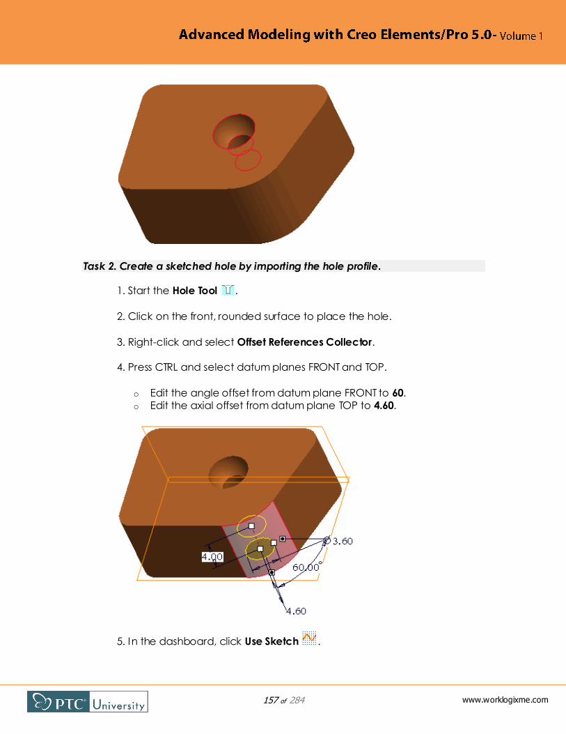
157 of 284
www.worklogixme.com
Task 2. Create a sketched hole by importing the hole profile.
1. Start the Hole Tool .
2. Click on the front, rounded surface to place the hole.
3. Right-click and select Offset References Collector.
4. Press CTRL and select datum planes FRONT and TOP.
o Edit the angle offset from datum plane FRONT to 60.
o Edit the axial offset from datum plane TOP to 4.60.
5. In the dashboard, click Use Sketch .

158 of 284
www.worklogixme.com
o Click Open .
o In the Open Section dialog box, select hole_section.sec and click
Open.
6. Click Complete Feature .
7. In the model tree, right-click feature CUT and select Resume.
8. Spin the model to v iew the sketched hole cross-sections.

159 of 284
www.worklogixme.com
This completes the procedure.
4.4 Creating On Point Holes
You can place a hole by selecting a datum point. The datum point must be
created on a surface. When you select the datum point, the system positions the hole perpendicular to the surface referenced by the datum point, and the hole
is center aligned with the datum point. This method is useful for placing holes on
contoured surfaces, when you want the hole axis to be normal to the surface
location.
Procedure: Creating On Point Holes
Scenario
Create a hole on a datum point.

160 of 284
www.worklogixme.com
Holes_On-Pnt hole_on-pnt.prt
Task 1. Create a hole on a datum point.
1. Start the Hole Tool from the feature toolbar.
2. Start the Datum Point Tool from the feature toolbar.
o Select the front, right, rounded corner surface.
3. Right-click and select Offset References.
4. Press CTRL and select datum planes RIGHT and FRONT.
o Edit the offset from datum plane RIGHT to 17.
o Edit the offset from datum plane FRONT to 18.
5. Click OK from the Datum Point dialog box.

161 of 284
www.worklogixme.com
6. In the dashboard, click Resume Feature .
7. Edit the hole diameter to 3.
8. Edit the hole depth to To Next .
9. Click Complete Feature .
10. Expand Hole 1 in the model tree.
11. Notice the embedded datum point.
12. Right-click Hole 1 and select Edit.

162 of 284
www.worklogixme.com
13. Notice that you can edit the datum point offset dimensions.
This completes the procedure.

163 of 284
www.worklogixme.com
Check Your Knowledge
1. Which of the following is a requirement for the sketch when creating a
sketched hole?
A - A geometry centerline must be sketched.
B - The sketch can be open or closed.
C - The hole must be sketched horizontally.
D - All of the above.
E - A and C only.
2. Can you use a Hole feature to model a constant diameter hole with the shape
of a drill point at the bottom?
A - Yes
B - No
3. Which thread type is available when creating a Standard hole?
A - ISO
B - UNC
C - UNF
D - All of the above
4. Which of the following is a method to dimension a drilled hole?
A - Bottom
B - Shoulder
C - Tip
D - End
E - All of the above
F - B and C only

164 of 284
www.worklogixme.com
5. True or False? Only certain holes can be made into a Standard hole. Radial
and diameter holes cannot be made Standard.
A - True
B – False

165 of 284
www.worklogixme.com
Module 5
Advanced Drafts and Ribs
Module Overview
With the draft feature, you can create tapered or angled surfaces from existing
geometry. It is common to create drafted surfaces on molded or cast parts,
however the draft feature can also be used to create this type of geometry for
everyday modeling tasks. It is also common to add ribs on molded and cast
parts for increased structural rigidity.
In this module, you learn how to utilize several advanced draft options, such as
drafting intent surfaces, drafting with multiple angles, and using different features
for splits. You also learn how to create trajectory ribs.

166 of 284
www.worklogixme.com
5.1 Drafting Intent Surfaces
You can select intent references within the Draft tool. Using intent references creates robust references to ―concepts‖ rather than explicit surface id's such as
side surfaces or end surfaces. Intent surfaces work well for drafts when
referencing all surfaces from a single feature. For example, in the figures, intent
surfaces are used to draft all surfaces of the hex cut. When the sketch for the hex
cut is modified, the draft feature automatically updates. Had the surfaces been
selected individually, the draft feature would have failed.
When geometry from multiple features must be selected, you should use
methods such as Loop surfaces and Surface and Boundary.
Procedure: Drafting Intent Surfaces
Scenario
Draft a part model using intent surfaces.
Draft_Intent-Surfs draft_intent-surfs.prt
Task 1. Draft a part model using intent surfaces.
1. Start the Draft Tool from the feature toolbar.
2. Right-click to query and select the intent surfaces of the inner hex cut
feature.

167 of 284
www.worklogixme.com
3. Press CTRL, right-click to query, and select the outer cylindrical intent
surfaces.
4. Right-click and select Draft Hinges.
o Select datum plane TOP.

168 of 284
www.worklogixme.com
5. In the dashboard, select the Split tab.
o Select Split by draft hinge as the Split option.
o Select Draft sides dependently as the Side option.
6. Edit the draft angle to 10.
7. In the dashboard, click Reverse Angle .
8. Click Complete Feature .
9. Click Plane Display to disable their display.
10. Edit the definition of Sketch 2.

169 of 284
www.worklogixme.com
o Sketcher display: o Drag a window around the hex sketch and press DELETE.
o Click Center and Point Circle and sketch a circle.
o Click Select One By One and edit the diameter to 10.
o Click Done Section .
11. Press CTRL + D to orient to the Standard Orientation.
12. Notice that the draft automatically updated without failing.
This completes the procedure.

170 of 284
www.worklogixme.com
5.2 Creating Drafts with Multiple Angles
You can create draft features that contain multiple angles. To create additional angles in the draft feature you use the Angles tab in the dashboard, as shown in
the upper-right figure. In addition to its own draft angle value, you can also
specify the following two items for each draft angle:
Reference — The selected entity on which the draft angle lies. You can
either click on this collector and select a new edge reference, or you can
drag the ―dot‖ in the graphics window onto a new reference. Any edge
of the drafted surface can be used for the Reference.
Location — The length ratio value along the Reference edge. For
example, if you want the draft angle to reside at the midpoint of the
reference you would specify a Location value of 0.5, as shown in the
figures. You can either type a different location value in the Angles tab, or
you can drag the ―dot‖ in the graphics window to a new location.
You can right-click an angle in the Angles tab to perform the following
operations:
Add Angle — Enables you to add additional draft angles. You can also
right-click a draft angle ―dot‖ to add additional angles.
Delete Angle — Enables you to delete the draft angle you right-clicked.
You can also right-click a draft angle ―dot‖ to delete that particular draft
angle.
Flip Angle — Flips the direction of the draft at the selected angle location.
You can also right-click the drag handle to flip the angle. In the lower-right
figure, the 8 degree draft angle was flipped.
Make Constant — Deletes all draft angles except the first one.

171 of 284
www.worklogixme.com
The Reverse Pull Direction option in the dashboard flips the pull
direction for all draft angles. To flip the draft direction for a specific
draft angle, right-click on its drag handle and select Flip Angle.
The Adjust angles to keep tangency option forces the resultant draft surfaces to
be tangent. This option is only available for a single draft angle, as drafts with
multiple angles always keep surfaces tangent.
Procedure: Creating Drafts with Multiple Angles
Scenario
Create a draft with multiple draft angles on a part model.
Draft_Mult-Angles draft_multiple-angles.prt
Task 1. Create a draft with multiple draft angles on a part model.
1. Start the Draft Tool from the feature toolbar.
o Select the right face to draft.
2. Right-click and select Draft Hinges.
o Select the top surface.

172 of 284
www.worklogixme.com
3. In the dashboard, select the Angles tab.
o Right-click the existing angle and select Add Angle twice.
4. In the graphics window, click the angle dots and drag them to the
outside and the center of the surface edge.
5. From the back, edit the angles to 15, 10, and 8.

173 of 284
www.worklogixme.com
6. In the dashboard, click Reverse Pull Direction .
7. Notice that all three angles have flipped.

174 of 284
www.worklogixme.com
8. In the Angles tab of the dashboard, right-click the 8 angle and select
Flip Angle.
9. Click Complete Feature .
This completes the procedure.

175 of 284
www.worklogixme.com
5.3 Using the Extend Intersect Surfaces Draft Option
The Extend intersect surfaces option becomes valuable when resulting draft geometry encounters an edge of the model. By default, the system
automatically creates the draft geometry so that it overhangs the edge of the
model, as shown in the upper figure.
You can use the Extend intersect surfaces draft option to create different
resultant geometry. When this option is selected, Pro/ENGINEER tries to extend
the draft to meet the adjacent surface of the model. If the draft cannot extend
to the adjacent model surface, the model surface extends into the draft surface,
as shown in the lower figure. If neither of these cases are possible, the system
reverts to creating a draft surface that overhangs the edge of the model as if the
option were not selected.
Procedure: Using the Extend Intersect Surfaces Draft Option
Scenario
Use the Extend intersect surfaces draft option in a part model.
Draft_Extend-Intersect extend-intersect.prt
Task 1. Use the Extend intersect surfaces draft option in a part model.
1. Start the Draft Tool from the feature toolbar.
o Select the right surface of the small rectangle.
2. Right-click and select Draft Hinges.

176 of 284
www.worklogixme.com
o Select the top surface of the small rectangle.
3. Drag the draft angle outward to 30 degrees.
4. Click Preview Feature .
5. Click Resume Feature .

177 of 284
www.worklogixme.com
6. In the dashboard, select the Options tab.
o Select the Extend intersect surfaces check box.
7. Click Complete Feature .
8. Notice that the model surface has extended into the draft surface.
This completes the procedure.
5.4 Creating Drafts Split at Sketch
You can specify a sketch to be used as the split object. This enables you to
create custom split lines. When you select an existing sketch as the split object, it
becomes linked. However, you can unlink the sketch if desired. You can also
define a new sketch. If the sketch does not lie on the draft surface,
Pro/ENGINEER projects it onto the draft surface in the direction normal to the
sketching plane. The sketch in the upper figure was used as the Split object for the draft in the lower figure.

178 of 284
www.worklogixme.com
Procedure: Creating Drafts Split at Sketch
Scenario
Create a draft split at a sketch.
Draft_Split-Sketch draft_split-sketch.prt
Task 1. Create a draft split at a sketch.
1. Start the Draft Tool from the feature toolbar.
o Select the large, front surface containing the sketch.
2. Right-click and select Draft Hinges.
o Select the top surface of the left rectangular ―step.‖
3. Drag the angle so the upper draft portion goes into the model.
4. In the dashboard, select the Split tab.
o Select Split by split object as the Split option.
o Select sketch SPLIT_SKETCH.
o Select Draft second side only as the Side option.
5. Drag the angle so the draft goes into the model.

179 of 284
www.worklogixme.com
6. Click Preview Feature .
7. Click Resume Feature .
8. In the dashboard, select the Split tab.
o Select Draft first side only as the Side option.
9. Click Preview Feature .
10. Click Resume Feature .
11. In the dashboard, select the Split tab.
o Select Draft sides independently as the Side option.
o Edit both draft angles to 7 so the draft goes into the model.

180 of 284
www.worklogixme.com
12. Click Complete Feature .
This completes the procedure.
5.5 Creating Drafts Split at Curve
You can create a draft that splits at a ―waistline‖ curve. This causes the material at the curve to remain constant. In the figures, the curve shown in the left figure
was used as the draft hinge. The draft was then split at this draft hinge to create
the resulting geometry in the right figure.
If you specify a curve as the draft hinge you must also specify a separate pull
direction reference.

181 of 284
www.worklogixme.com
Procedure: Creating Drafts Split at Curve
Scenario
Create a draft split at a curve.
Draft_Split-Curve draft_split-curve.prt
Task 1. Create a draft split at a curve.
1. Start the Draft Tool from the feature toolbar.
o Select the front surface.
2. Right-click and select Draft Hinges.
o Select the curve.
3. Right-click and select Pull Direction.
o Select datum plane TOP.
4. Edit the draft angle to 10.

182 of 284
www.worklogixme.com
5. In the dashboard, click Reverse Angle .
6. Click Preview Feature .
7. Click Resume Feature .
8. In the dashboard, select the Split tab.
o Select Split by draft hinge as the Split option.
o Select Draft sides dependently as the Side option.
9. Click Reverse Angle as necessary to remove material.
10. Click Complete Feature .
11. Notice that this draft has removed material from the top and bottom
of the model.

183 of 284
www.worklogixme.com
This completes the procedure.
5.6 Creating Drafts Split at Surface
You can create a draft that splits at a ―waistline‖ surface, causing material at the surface to be added. This type of draft enables you to select additional draft
hinges. To select a second hinge, you must first split the draft surfaces. The model
remains the same size at both draft hinge locations. In the lower-left figure, the
selected surface is used as the split object. Once this split object was defined, a
second draft hinge was able to be added, as shown in the lower-right figure. The
resulting geometry is shown in the upper-right figure.

184 of 284
www.worklogixme.com
Procedure: Creating Drafts Split at Surface
Scenario
Create a draft split at a surface.
Draft_Split-Surface draft_split-surface.prt
Task 1. Create a draft split at a surface.
1. Start the Draft Tool from the feature toolbar.
o Select the front surface.
2. Right-click and select Draft Hinges.
o Select an edge on the front of the top surface.
o Press SHIFT, cursor over an adjacent edge, right-click to query, and
select the upper Tangent chain.

185 of 284
www.worklogixme.com
3. Right-click and select Pull Direction.
o Select datum plane TOP.
4. Edit the draft angle to 10.
5. In the dashboard, select the Split tab.
o Select Split by split object as the Split option.
o Select the surface quilt.
6. Edit the lower draft angle to 10.
7. Click Reverse Angle for the lower draft angle as necessary.

186 of 284
www.worklogixme.com
8. In the dashboard, select the References tab.
9. Right-click and select Draft Hinges.
o Press CTRL and select an edge on the front of the bottom surface.
o Press SHIFT, cursor over an adjacent edge, right-click to query, and
select the bottom Tangent chain.
o The Draft hinges collector should contain two Tangent Chains.
10. Click Complete Feature .
11. In the model tree, right-click QUILT and select Hide.
12. Note that this draft has added material to the center of the model.
This completes the procedure.
5.7 Creating Drafts with Variable Pull Direction
You can create draft on models that contains variable pull directions. The
Variable Pull Direction Draft tool is located within the Advanced menu in the

187 of 284
www.worklogixme.com
main menu. I t sweeps a ruled surface normal to a specified draft hinge. You do
not specify surfaces to be drafted with the Variable Pull Direction Draft tool.
The Variable Pull Direction Draft tool also differs from the conventional Draft tool
in the following ways:
You can create draft sets within the Variable Pull Direction Draft tool,
similar to the Round and Chamfer tools. In the upper figure, the left and
right surfaces are drafted in one set, and the rear surface is drafted in a
second set.
You can specify a draft angle greater than 30 degrees.
The Pull Direction Reference Surface specified does not have to be planar.
You can specify a splitting surface with the Variable Pull Direction Draft tool. The
splitting surface causes the draft to split at the selected surface reference. This
enables you to specify a different draft angle on each side of the splitting
surface reference. In the lower figure, the draft angle above the splitting surface
is 30 degrees, and the draft angle below the splitting surface is 10 degrees.
Procedure: Creating Drafts with Variable Pull Direction
Scenario
Create variable pull direction draft features.

188 of 284
www.worklogixme.com
Draft_Var-Pull draft_var-pull.prt
Task 1. Create a variable pull direction draft feature with two sets.
1. Orient to the SETS v iew orientation.
2. Click Insert > Advanced > Variable Pull Direction Draft from the main
menu.
3. Select the top U-shaped surface as the Pull Direction Reference
Surface.
4. Select the References tab from the dashboard.
o Click in the Draft Hinges collector.
o Press CTRL and select the two upper side edges.
o Edit the draft angle to 14.

189 of 284
www.worklogixme.com
5. In the References tab, click *New set.
6. Select the upper rear edge.
7. In the graphics window, right-click and select Make variable.
8. Edit the left draft angle to 20, and the right draft angle to 30.
9. Click Complete Feature .

190 of 284
www.worklogixme.com
Task 2. Create a variable pull direction draft feature with a splitting surface.
1. Orient to the SPLIT v iew orientation.
2. In the model tree, right-click SPLIT and select Unhide.
3. De-select the feature.
4. Click Insert > Advanced > Variable Pull Direction Draft.
5. Select the top U-shaped surface as the Pull Direction Reference
Surface.
6. Right-click and select Draft Hinges.
7. Select the front, upper edge.
8. In the dashboard, select the References tab.
o Select the Splitting Surfaces check box.
9. Select surface SPLIT.
10. Notice the draft splits at the surface location.

191 of 284
www.worklogixme.com
11. Edit the upper draft angle to 21.
12. Edit the lower draft angle to 10.
13. Click Complete Feature .
14. In the model tree, right-click SPLIT and select Hide.

192 of 284
www.worklogixme.com
This completes the procedure.
5.8 Creating Trajectory Ribs
Creating Trajectory Ribs Theory
Like the traditional Profile Rib, Trajectory Ribs
are typically used to strengthen parts;
however, with a Trajectory Rib, you sketch
the rib centerline from a top view, instead of
sketching the rib from a side view. You can
select an existing sketch or sketch internal to
the Trajectory Rib.
The system can add material above or
below the sketch, but with a Trajectory Rib
the thickness is always applied symmetric about the sketch. You can also choose
to add draft or rounds as part of the Trajectory Rib feature.
The sketch used for a Trajectory Rib has special abilities:
The rib will self-extend to find solid material. Therefore, you do not have to
extend the sketch and align it to the part. If sketched beyond the model,
the rib will automatically trim itself to the model boundaries.
o In the case of a model with complex wall geometry, it is best to
allow the system to self-extend the rib to the model.
The rib sketch can intersect itself. This enables quick and easy sketching to
achieve the desired rib.

193 of 284
www.worklogixme.com
The rib sketch can pass through existing features, such as screw boss
geometry. The systems simply ignores the existing solid geometry, and
continues the rib in the next free space.
The rib sketch can have multiple open loops, unlike sketches for most
other solid features. This enables you to sketch multiple unconnected ribs
in the same feature.
The Trajectory Rib has several options:
You can add Draft. Draft is added such that the exposed end of the rib
maintains its width, and you can specify the angle that tapers outward
and towards the base of the model.
You can add rounds on the exposed edges of the rib. With this option you
can round the top of the rib using a two-tangent round. The size of the
two-tangent round is controlled by the width of the rib, similar to creating
a full round. You can also create the rounds by specifying radius values
manually.
You can add rounds on the internal edges of the rib. With this option you
can round the bottom of the rib using a radius value that is equal to the
top (exposed edges), or by specifying radius values manually.
Once a Trajectory Rib is created, there are some additional options:
You can right-click the rib and select Externalize Rounds. This separates
the rounds from the rib feature, and creates a round feature in the model
tree. The rounds can then be further customized.
If you did not add rounds within the rib feature, the internal and exposed
edges of the rib are made available for quick selection by querying to an
intent edge set.
Procedure: Creating Trajectory Ribs
Scenario
Create rib features on a part model.
Trajectory_Rib trajectory_rib.prt
Task 1. Create rib features on a part model.
1. Start theTrajectory Rib Tool from the feature toolbar.
2. Right-click and select Define Internal Sketch.
3. Select datum plane RIB.

194 of 284
www.worklogixme.com
4. Click Sketch.
5. Sketcher display:
6. Click No hidden .
7. Right-click and select References.
8. Select the outer circular edge on the boss feature on the right and click
Close.
9. Right-click and select Line, and sketch two lines.
10. Click Done Section .
11. Drag the width handle to 3.
12. Click Complete Feature .

195 of 284
www.worklogixme.com
13. Click Shading .
14. Press CTRL + D.
15. With the rib still selected, right-click and select Edit Definition.
16. Click Add Draft .
17. Select the Shape tab and type 2 for the Angle.
18. Click Add Exposed Rounds .
19. In the Shape tab, click Specified Value.
20. Type 1 for the radius.

196 of 284
www.worklogixme.com
21. Select the Placement tab and click Edit.
22. Click No hidden .
23. Right-click and select Line, and then sketch an additional line.
24. Sketcher display:
25. Click Done Section .
26. Click Shading .
27. Press CTRL + D.
28. Click Add Internal Rounds .
29. Select the Shape tab, and click Same As Top.

197 of 284
www.worklogixme.com
30. Click Complete Feature .
31. Notice that a single rib feature is created in the model tree.
32. With the rib still selected, right-click and select Externalize Rounds, then
click OK.
33. Notice that a separate round feature is created in the model tree.

198 of 284
www.worklogixme.com
This completes the procedure.

199 of 284
www.worklogixme.com
Module 6
Advanced Shells
Module Overview
With the shell feature, you can hollow out the inside of a solid, leaving a shell of a
specified wall thickness. You can also select surfaces to be assigned a different
thickness as well as specify surfaces to be removed. You can even create partial
shells to exclude surfaces from being shelled.
In this module, you learn how to create the shell feature and utilize several shell
options, such as excluding surfaces, removing surfacing, and creating shells of
multiple thicknesses.

200 of 284
www.worklogixme.com
6.1 Analyzing Shell References and Thickness Options
Analyzing Shell References and Thickness Options Theory
You can manipulate a Shell feature by specifying surfaces to remove, specifying
surfaces of non-default thickness, and flip which side of the model the shell
thickness is added.
Removing Surfaces
The References tab in the dashboard contains the Removed surfaces collector.
You can select surfaces to be removed as part of the shell operation. In the
lower figures, the top surface has been removed from the Shell feature. If you do
not select any surfaces for removal, a ―closed‖ shell is created, with the whole
inside of the part hollowed out, as shown in the upper-right figure. You can view
the shell by creating a cut or cross-section.
Specifying Non-Default Thickness Surfaces
The References tab in the dashboard also contains the Non-default thickness
collector. You can select surfaces to which a different thickness dimension is
applied than the rest of the Shell feature. For each surface included in this
collector, you can specify a different individual thickness value. In the lower-right
figure, two surfaces have been assigned different non-default thicknesses of
20mm and 30mm, while the remainder of the model is shelled at a thickness of
10mm.
Inverting Shell Thickness
In the dashboard you can flip the shell thickness by clicking Change Thickness
Direction . This causes the shell thickness to be added to the outside of the
original model, creating a void in the shape of the original model.
Procedure: Analyzing Shell References and Thickness Options
Scenario
Analyze shell references and thickness options in a part model.
References_Thickness ref_thick.prt
Task 1. Specify surfaces to remove and surfaces to make non-default thickness.
1. In the model tree, right-click CUT and select Resume.

201 of 284
www.worklogixme.com
2. Notice that the model is shelled, but that surface references have not
been removed.
3. Right-click CUT and select Suppress.
o Click OK.
4. Edit the definition of Shell 1.
5. Select the top surface to remove it.
6. Right-click and select Non Default Thickness.
7. Select the right, flat surface.
8. Drag the non-default thickness to 20.

202 of 284
www.worklogixme.com
9. In the dashboard, select the References tab.
10. Notice that there is one reference specified to be removed, and one
reference specified as non-default thickness.
11. Press CTRL and select the left, flat surface to be non-default thickness,
also.
o In the dashboard, edit the thickness to 30.
12. In the dashboard, click Change Thickness Direction .
13. Click Preview Feature .

203 of 284
www.worklogixme.com
14. Click Resume Feature .
15. Click Change Thickness Direction .
16. Click Complete Feature .
17. Right-click Shell 1 and select Edit.
18. Spin the model and notice the dimensions.
This completes the procedure.

204 of 284
www.worklogixme.com
6.2 Excluding Surfaces from Shells
Sometimes, you do not want all surfaces of a part model to be
shelled. For example, you may not
want the grips in the upper-right
figure to be shelled. You can exclude
surfaces from the Shell feature.
Excluding surfaces enables you to
select one or more surfaces and
exclude them from the Shell feature.
In the lower-left figure, surfaces are
selected to be excluded from the
shell. In the lower-right figure the shell
has been completed, and the grips
are not shelled.
When specifying surfaces for
exclusion, you can open the Surface Sets dialog box. The Surface Sets dialog box
enables you to further add Individual Surfaces, Seed and Boundary Surfaces,
and Excluded Surfaces.
Procedure: Excluding Surfaces from Shells
Scenario
Exclude surfaces from the shell feature of a part model.
Excluding_Surfs exclude_surfs.prt
Task 1. Exclude surfaces from the shell feature of a part model.
1. In the model tree, select Shell 1.
2. Notice that the grips on the cap are shelled.

205 of 284
www.worklogixme.com
3. Edit the definition of Shell 1.
4. Orient to the standard orientation.
5. Right-click and select Exclude Surfaces.
6. Press CTRL and select all five surfaces from the patterned grip near the
shell dimension.
7. Click Preview Feature .
8. Click Named View List and select 3D.
9. Notice that the grip is no longer shelled, as it has been excluded.
10. Click Resume Feature and orient to the standard orientation.
11. In the dashboard, select the Options tab.
o Right-click Individual Surfaces and select Remove.
12. Select a surface on the grip again.

206 of 284
www.worklogixme.com
13. Press SHIFT and select the surface of the upper main round on the cap.
14. Notice that you have initiated a Seed and Boundary Surfaces set.
15. In the Options tab, click Details.
16. In the Surface Sets dialog box, select Seed and Boundary Surfaces.
o Press CTRL and select the other half of the round.
o Press CTRL and query-select the bottom, flat surface of the model.
17. In the Surface Sets dialog box, select Excluded Surfaces.
o Press CTRL and select the two outer halves of the cap.
o Click OK.

207 of 284
www.worklogixme.com
18. Click Complete Feature .
19. Click Named View List and select 3D.
20. Notice that all grips are now excluded from the Shell feature.
This completes the procedure.
6.3 Extending Shell Surfaces
In many cases there are two possible geometry results when partially shelling a feature. The result depends on the surfaces that will be used to close the solid. In
the upper figure, the model has been shelled. In the lower figures, the cylinder
feature surfaces have been excluded from the Shell feature. The two results are:
Extend inner surfaces — Forms a cover over the inner surfaces of the shell
feature. This is the default option, and is shown in the lower-left figure. The
inner surfaces of the shell were extended in front of the excluded cylinder
surfaces.
Extend excluded surfaces — Forms a cover over the excluded surfaces of
the shell feature. In the lower-right figure, the excluded cylinder surfaces
were extended into the shell.
Procedure: Extending Shell Surfaces
Scenario
Experiment with the options available for extending surfaces of a Shell feature.

208 of 284
www.worklogixme.com
Extend_Options extend_surfaces.prt
Task 1. Experiment with the options available for extending surfaces of a Shell
feature.
1. In the model tree, select Shell 1.
2. Notice that the Shell feature hollows out the cylinder portion of the
model.
3. Edit the definition of Shell 1.
4. Right-click and select Exclude Surfaces.
5. Press CTRL and select the front, back, and cylindrical surfaces of the
cylinder.

209 of 284
www.worklogixme.com
6. Click Preview Feature .
7. Notice that the cylinder is excluded from the Shell feature.
8. Click Resume Feature .
9. In the dashboard, select the Options tab.
o Select the Extend excluded surfaces option.
10. Click Complete Feature .
11. Notice that the cylinder extends into the Shell feature.
This completes the procedure.

210 of 284
www.worklogixme.com
6.4 Analyzing Shell Corner Options
There are two options to control situations when a Shell feature with an excluded surface breaks through the solid.
Concave corners — Prevents the shell from cutting through the solid at
concave corners.
Convex corners — Prevents the shell from cutting through the solid at
convex corners.
The upper-right figure depicts a shelled block that contains a convex chamfer
(at the top) and a concave chamfer (at the bottom). In the lower figures, the
chamfer surfaces have been excluded from the shell. In the lower-left figure the
shell is prevented from penetrating the solid at concave corners. Consequently,
the concave chamfer no longer penetrates the solid, while the convex chamfer
still does penetrate the solid.
Conversely, in the lower-right figure the shell is prevented from penetrating the
solid at convex corners. Consequently, the convex chamfer no longer
penetrates the solid, while the concave chamfer still does penetrate the solid.
Procedure: Analyzing Shell Corner Options
Scenario
Analyze the shell corner options of a part model.
Corner_Options concave_convex.prt
Task 1. Analyze the shell corner options of a part model.
1. Edit the definition of Shell 1.
2. Right-click and select Exclude Surfaces.
3. Select the surface of the convex chamfer.

211 of 284
www.worklogixme.com
4. Select the Options tab.
5. Verify that the Concave corners option is selected.
6. Click Preview Feature .
7. Notice that the Shell feature is cutting through.
8. Click Resume Feature .
9. In the dashboard, select the Options tab.
o Select the Convex corners option.
10. Click Complete Feature .
11. Press CTRL and select Chamfer 1 and Shell 1.
12. Right-click and select Suppress.
o Click OK.
13. De-select all geometry.
14. Press CTRL and select Chamfer 2 and Shell 2.
15. Right-click and select Resume.

212 of 284
www.worklogixme.com
16. Edit the definition of Shell 2.
17. Right-click and select Exclude Surfaces.
18. Select the surface of the concave chamfer.
19. Select the Options tab.
20. Verify that the Convex corners option is selected.
21. Click Preview Feature .
22. Notice that the Shell feature is cutting through.
23. Click Resume Feature .
24. In the dashboard, select the Options tab.

213 of 284
www.worklogixme.com
o Select the Concave corners option.
25. Click Complete Feature .
This completes the procedure.

214 of 284
www.worklogixme.com
Check Your Knowledge
1. True or False? You must select a surface to remove when creating a shell
feature.
A - True
B - False
2. Which statement is TRUE regarding the Shell feature?
A - Multiple surfaces can be removed.
B - A negative shell thickness value can be entered.
C - Specific surfaces can be selected to assign them a different thickness
from the rest of the model.
D - All of the above
3. True or False? When creating a shell feature, it is possible to exclude portions of
the model from the shelling operation.
A - True
B - False
4. Which of the following is not a way to manipulate a Shell feature?
A - Specifying surfaces to remove.
B - Specifying surfaces of non-default thickness.
C - Specifying on which side of the model shell thickness is added.
D - Specifying surfaces to keep.
E - All of the above.
5. True or False? When specifying surfaces to be non-default thickness, only one
non-default thickness value is allowed.
A - True
B – False

215 of 284
www.worklogixme.com

216 of 284
www.worklogixme.com
Module 7
Advanced Rounds and Chamfers
Module Overview
Pro/ENGINEER enables you to create finishing features, such as rounds and
chamfers. These features can be placed directly on design models by selecting
suitable references. You can create complex geometry by defining transitions
between various round and chamfer sets. You can use advanced options to
address placement ambiguity in rounds and chamfers, as well as trim round and
chamfer geometry.

217 of 284
www.worklogixme.com

218 of 284
www.worklogixme.com
7.1 Analyzing Round Profile
Creating Conic Rounds
You can create rounds that have profiles other than that of a circular arc. You
can define a round that uses a conic round profile. There are two options
available for conic rounds:
Conic — Defines a round profile to be
conic using a single distance value. A
conic shape factor (RHO value) can also
be controlled.
D1 x D2 Conic — Defines a round
profile to be conic using two distance
values. A conic shape factor (RHO
value) can also be controlled.
Both conic round profiles maintain
tangency like that of the circular arc
round, but can be used to create sharper or shallower rounds using the RHO
parameter. In the lower-left figure, the rounds are conic rounds.
Creating Curvature Continuous Rounds
You can also define a round that uses a curvature continuous spline as a round
profile. This option is particularly useful on models where maintaining a curvature
continuity is important across rounded surfaces. The system calculates the round
then applies the spline profile. You use the curvature continuous round profile
with single or variable radius rounds.
There are two options for curvature continuous rounds:
C2 Continuous — Defines the round profile to be curvature continuous
(C2) using a single distance (radius) value. A conic shape factor (RHO
value) can also be controlled.
D1xD2 C2 — Defines the round profile to be curvature continuous (C2)
using two distance (radius) values. A conic shape factor (RHO value) can
also be controlled.
In the lower-right figure, the rounds are curvature continuous rounds.
Using the RHO Parameter

219 of 284
www.worklogixme.com
You can specify the value for the RHO parameter of the conic or curvature
continuous round to create elliptical, parabolic, or hyperbolic rounds. Higher
RHO values create a more peaked conic shape, and lower RHO values create a
more flat conic shape.
The following RHO values create specific conic section geometry:
0.05 to < 0.50 = Elliptical
0.5 = Parabolic
> 0.50 to 0.95 = Hyperbolic
√2-1 = Quadrant of an Ellipse
Procedure: Analyzing Round Profile
Scenario
Analyze the various available round profiles in a part model.
Round_Profile round_profile.prt
Task 1. Create a Conic round.
1. Press CTRL and select Round 1 and Round 2.
2. Orient to the FRONT v iew to observe their profiles.
3. Click View > Orientation > Previous.
4. Edit the definition of Round 1.

220 of 284
www.worklogixme.com
5. In the dashboard, select the Sets tab.
o Edit the drop-down list from Circular to Conic.
6. Drag the square conic parameter handle left and right and observe the
round shape changing.
7. Edit the Conic parameter value to 0.70 in the dashboard.
8. Click Complete Feature .
Task 2. Create a D1 x D2 Conic round.
1. Edit the definition of Round 2.

221 of 284
www.worklogixme.com
2. In the dashboard, select the Sets tab.
o Edit the drop-down list from Circular to D1 x D2 Conic.
o Edit the D1 and D2 values to 5 and 10, respectively.
o Edit the Conic parameter value to 0.35.
3. Press CTRL and select Round 1 and Round 2.
4. Orient to the FRONT v iew to observe their profiles.
Task 3. Create a C2 Continuous and D1xD2 C2 round.
1. Click View > Orientation > Previous.
2. Edit the definition of Round 3.

222 of 284
www.worklogixme.com
3. In the dashboard, select the Sets tab.
o Edit the drop-down list from Circular to C2 Continuous.
4. Edit the Conic parameter value to 0.70 in the dashboard.
5. Click Complete Feature .
6. Edit the definition of Round 4.
7. In the dashboard, select the Sets tab.
o Edit the drop-down list from Circular to D1 x D2 C2.
o Edit the D1 and D2 values to 7 and 5, respectively.
o Edit the Conic parameter value to 0.35.
8. Click Complete Feature .

223 of 284
www.worklogixme.com
This completes the procedure.
7.2 Analyzing Round Creation Methods
You can create a round using either the Rolling ball method or Normal to spine
method. Rolling ball is the default round creation method used by Pro/ENGINEER.
It uses a standard round algorithm, where the system creates round set pieces by
―rolling‖ a theoretical spherical ball along the geometry, following any
tangencies. The path left by the ball forms the round.
If the Rolling ball method is not successful, like in the left image of the lower
figure, then you can try the Normal to spine method. The Normal to spine
method works well for situations where the round changes direction quickly. For a
Normal to spine round, the system sweeps an arc cross-section normal to a spine
curve, where the spine curve is the edge you select to be rounded. You can also
use the Conic and D1 x D2 Conic profiles with the Normal to spine method.
Procedure: Analyzing Round Creation Methods
Scenario
Analyze the round creation methods in a part model.
Round_Method round_method.prt
Task 1. Analyze the round creation methods in a part model.
1. Start the Round Tool from the feature toolbar.
2. Select the edge between cylinders.
3. Edit the radius to 4.
4. Click Preview Feature .

224 of 284
www.worklogixme.com
5. Click Resume Feature .
6. Edit the radius to 5.
7. Click Preview Feature .
8. Notice that the round fails.
9. Click Cancel from the Troubleshooter dialog box.
o Click Yes.
10. Click Resume Feature .
11. In the dashboard, select the Sets tab.
o Edit the drop-down list from Rolling ball to Normal to spine.
12. Click Preview Feature .

225 of 284
www.worklogixme.com
13. Click Resume Feature .
14. Orient to the FRONT v iew.
15. In the dashboard, select the Sets tab.
o Edit the drop-down list from Circular to Conic.
o Accept the default Rho value.
16. Click Complete Feature .
This completes the procedure.
7.3 Creating Rounds Through Curve
You can control the radius of a round by using edges or curves. The round radius follows the selected reference, with respect to the edges being rounded. The
rounds can also add or remove material. In the upper figure, two different rounds
were created, one on each peg. The round on the left peg adds material, while
the round on the right removes material. In the lower figure, the edge is selected
for rounding in the left image. In the middle image the curve is specified for the
round to be created through. The right image displays the final round.
Procedure: Creating Rounds Through Curve
Scenario
Create rounds through curve.
Rounds_Thru_Curve thru_curve.prt
Task 1. Create rounds through curve.

226 of 284
www.worklogixme.com
1. Start the Round Tool from the feature toolbar.
2. Select the edge of the larger cylinder on the right.
3. In the dashboard, select the Sets tab.
o Click Through curve and select the bottom edge of the smaller
cylinder.
4. Click Complete Feature .
5. Notice the round is removing material.
6. Start the Round Tool .
7. Select the bottom edge of the small cylinder on the left.

227 of 284
www.worklogixme.com
8. In the dashboard, select the Sets tab.
o Click Through curve and select the top edge of the larger cylinder.
o Press SHIFT and select the other larger cylinder edge.
9. Click Complete Feature .
10. Notice that the round is adding material.
11. Orient to the Standard Orientation.
12. Start the Round Tool .
13. Select the top, right edge.
14. Right-click and select Through curve.

228 of 284
www.worklogixme.com
o Select the spline.
15. Click Complete Feature .
16. Start the Round Tool .
17. Select the concave edge.
18. Right-click and select Through curve.
o Select the spline.

229 of 284
www.worklogixme.com
19. Right-click and select Add set.
20. Select the top, right edge.
21. Right-click and select Through curve.
o Select the spline.
22. Click Complete Feature .
This completes the procedure.
7.4 Creating Variable Radius Rounds
By default, when you create a round, Pro/ENGINEER creates a constant round, where a single radius is applied. However, you can also create a variable round.
A variable round is one that
has multiple radius values.
You can convert a constant
radius to a variable radius
and v ice versa. To convert a
constant radius to a variable
radius, you right-click in the
graphics window or Radius
table in the Sets tab and
select Make variable.
Conversely, you convert a

230 of 284
www.worklogixme.com
variable radius to a constant radius by right-clicking in the graphics window or
Radius table in the Sets tab and selecting Make constant.
Each variable round must have the following two items defined:
Location — Defines where the variable round occurs in the part model.
You can define each variable round location in either of the following
ways:
o Ratio — The length ratio value along the Reference edge. For
example, if you want the variable round to reside at the midpoint
of the Reference edge you would specify a Ratio value of 0.5. You
can either type a Ratio value in the Sets tab, or you can drag the
location handle in the graphics window to a new location. In the
lower-right figure, the lower round has a ratio of 0.85 defined. That
is, it is 0.85, or 85% of the way along the highlighted reference.
o Reference — Enables you to select a specific reference location for
the variable round to occur. In the lower-right figure, the upper
round location is defined at datum point PNT0.
Radius — Defines the round radius value at the defined location. You can
define each round radius value in either of the following ways:
o Value — Enables you to type the desired round value as a
numerical value. The round radius value displays in the Radius
table. In the lower-left figure, the upper radius has a value of 14,
while the lower radius value is 7.
o Reference — Enables you to specify the radius by using a
reference.
You can right-click a radius in the Radius table of the Sets tab to perform the
following operations:
Add radius — Enables you to add additional radii. You can also right-click
a radius handle to add additional radii.
Delete — Enables you to delete the radius you right-clicked. You can also
right-click a radius handle in the graphics window to delete that particular
radius.
Make constant — Deletes all radii except the first one.
Procedure: Creating Variable Radius Rounds
Scenario
Edit an existing round to make it variable.
Rounds_Variable variable_rad.prt

231 of 284
www.worklogixme.com
Task 1. Edit an existing round to make it variable.
1. Edit the definition of Round 1.
2. Right-click and select Make variable.
3. In the dashboard, select the Sets tab.
o Notice that there are two radii.
4. In the graphics window, drag the round location handles to the far left
and right of the highlighted edge.
5. In the Sets tab, notice that the Location values for the left and right radii
are 1 and 0, respectively.
6. In the Sets tab, edit the Radius at the 1 Location to 18.
o Edit the Location Ratio Value from 1 to 0.9.

232 of 284
www.worklogixme.com
o Edit the distance Value from Ratio to Reference.
o Select the left vertex of the highlighted reference.
7. Drag the radius at the 0 location from 10 to 8.
8. Edit the Location Ratio Value from 0 to 0.20.
9. In the Sets tab, right-click in the table and select Add radius.
o Edit the distance Value from Ratio to Reference.
o Select datum point PNT0.
o Drag the radius value to 12.

233 of 284
www.worklogixme.com
10. In the graphics window, right-click on the last radius' handle and select
Add radius.
o Drag the new point around to the back of the large edge.
11. In the Sets tab, edit the Location Ratio Value to 0.5.
o Edit the Radius value from 12 to 8.

234 of 284
www.worklogixme.com
12. Click Complete Feature .
This completes the procedure.
7.5 Auto Round
The Auto Round tool enables you to
create a complex series of rounds quickly
and easily. Rounds that would take an
experienced modeler 30 minutes or more
(due to experimenting with round order
and transitions) can be created in
seconds with the Auto Round tool. The
auto round is a new feature type, and is
not created using the conventional
Round tool. Several individual rounds are
created as round sub-features within an auto round feature. The following

235 of 284
www.worklogixme.com
describes the technical aspects of the Auto Round tool, which lead to robust
rounding of a model:
The Auto Round tool creates rounds in an intelligent order as necessary to
set up tangency for subsequent rounds.
o The tool does not simply select edges and then round the selected
edges.
Round transitions are created as necessary by the Auto Round tool.
The Auto Round Player dialog box appears during round calculation. You
can stop regeneration and rewind or play back the different round
features being created by the Auto Round tool, if desired. You can insert features before the auto round in the model tree, and the
auto round will then round those features.
The Auto Round tool is designed to avoid feature failures. Sometimes
model geometry changes, and some of the rounds cannot be created. In
this case, the rounds are excluded and the Round tool will only round
what is possible.
The following are options within the Auto Round tool:
You can round concave edges, convex edges, or both.
o You can assign concave and convex edges different round radii.
You can round all solid edges, or choose a series of edges to exclude
from rounding. You can also round only a selection of edges.
Instead of an auto round feature with round sub-features, you can create
a group of standard round features.
o You can also right-click an existing auto round feature and convert
it to a group.
o A group of round features can be ungrouped, providing a series of
standard round features that can be edited or deleted individually.
Procedure: Auto Round
Scenario
Create a series of rounds quickly using an auto round on a complex model.
Auto_round auto_round.prt
Task 1. Utilize an auto round to create rounds on a complex model.
1. Click Insert > Auto Round.
o Edit the convex radius value to 1.0, if necessary.
o Select Same for the Concave radius value, if necessary.

236 of 284
www.worklogixme.com
o Select the Scope tab and observe the options.
o Click Complete Feature .
o The auto round will take a few moments to generate.
2. Select the auto round from the model tree, right-click, and select Edit
Definition.
o Select the Exclude tab.
o Press CTRL and select four edges to exclude.
3. Click Complete Feature .
o The auto round will take a few moments to generate.
4. Drag the Insert Indicator directly before the auto round feature.

237 of 284
www.worklogixme.com
o Select Sketch 1, right-click and select Unhide.
o With the sketch still selected, start the Extrude Tool .
o Drag the depth to 15.
o Click Complete Feature .
5. Right-click the Insert Indicator and click Cancel.
o Click Yes.
o Notice that the auto round has encompassed the inserted feature.
6. Select AutoRound1 from the model tree.
o Right-click and select Convert to Group.
o Click OK.
o Expand the local group (Group LOCAL_GROUP).
o Right-click the local group and select Ungroup.
o Notice that the auto round has been converted to a series of
standard Round features.

238 of 284
www.worklogixme.com
This completes the procedure.
7.6 Creating Rounds by Reference
By default, when you create a round you must specify its radius. However, you can choose to use a reference that defines the radius instead. You can specify a
point, vertex, or edge as the reference. The system updates the geometry
automatically for any changes made to the reference location. The lower-left
figure displays the resulting round geometry for the selected references. In the
lower-right figure, the height of the protrusion was decreased, and the datum
point position used by the upper round has been moved. Notice that the
resulting round geometry updated accordingly.
Procedure: Creating Rounds by Reference
Scenario
Redefine round radii from a value to a reference.
Round_By_Ref rad_by_ref.prt
Task 1. Redefine round radii from a value to a reference.
1. Edit the definition of Round 1.
2. In the dashboard, select the Sets tab.
o Notice that the Radius is 5.
o Edit the distance drop-down list from Value to Reference.
o Select the bottom right, front vertex.

239 of 284
www.worklogixme.com
3. Click Complete Feature .
4. Edit the definition of Round 2.
5. In the dashboard, select the Sets tab.
o Notice that the Radius is 4.
o Edit the distance drop-down list from Value to Reference.
o Select datum point PNT0.

240 of 284
www.worklogixme.com
6. Click Complete Feature .
7. In the model tree, right-click Extrude 1 and select Edit.
o Edit the height from 12 to 8.
8. In the model tree, select datum point PNT0, right-click, and select Edit.
o Edit the point value from 0.7 to 0.4.
9. Click Regenerate .
10. Notice that the feature geometry updates.

241 of 284
www.worklogixme.com
This completes the procedure.
7.7 Analyzing Round References and Pieces
Analyzing Round References Selection
By default, if you select an edge to be rounded, and that selected edge has
adjacent tangent edges, then the resulting round automatically propagates
around those tangent edges. However, you can manipulate which edges are
ultimately rounded by pressing SHIFT and using the Surface loop from to or One-
by-one selection options. These options enable you prevent the round from covering the whole tangent chain,
allowing you to select only the edges
you want to receive the round. In the
upper figure, the edges were selected
using a Surface loop from to. The
resulting geometry does not round the
top three edges, even though they
are tangent. When Surface loop from
to selection is used with the tool
started, you can even select edges
that are not tangent.
Analyzing Round Pieces
The Pieces tab in the dashboard enables you to further manipulate the round.
Using the Pieces tab you can perform the following functions:
Select a piece of the round from the model to remove it.
Trim the round by dragging the handles at the ends of the piece inward
so that less geometry is covered.
Extend the round by dragging the handles at the ends of the piece
outward so that more geometry is covered.

242 of 284
www.worklogixme.com
If you want to trim or extend a closed-loop round, simply remove a round piece
from the round first. This causes the handles to appear for trimming or extending.
In the lower figure, the bottom arc piece is excluded, which causes the handles
to display. The handles were used to trim the small corners so that they were not
rounded, either.
To enter the functionality that enables you to select pieces to be removed, you
must select the piece in the Pieces tab. Once you have excluded or removed a
piece of the round, the Pieces tab displays the piece as Edited. If you want to
include all pieces again, you can edit the selected Piece drop-down list back to
Included.
If you need to terminate a round other than at a round piece, you
can use the Stop at Reference transition type.
Procedure: Analyzing Round References and Pieces
Scenario
Create rounds using different selection references and pieces.
References_Pieces refs_pieces.prt
Task 1. Create rounds using different references and pieces.
1. Select Extrude 2.
o Select the front, left arc edge.
o Press SHIFT, and query-select the bottom Surface loop from to.
2. Start the Round Tool from the feature toolbar.
3. Edit the radius to 1 and click Complete Feature .
4. Notice that the round did not follow the tangent chain at the top.

243 of 284
www.worklogixme.com
5. Start the Round Tool .
6. Select an inner concave edge.
7. Notice that the entire tangent chain is to be rounded.
8. In the dashboard, select the Pieces tab.
o Select Piece 1.
o Select the bottom rounded arc to exclude it.
o Drag both handles up to exclude the small rounded corners.
9. Click Complete Feature .
10. Press CTRL + D to orient to the Standard Orientation.

244 of 284
www.worklogixme.com
11. Start the Round Tool .
12. Select the right front large arc. Notice the tangent chain.
13. Press SHIFT and select the left front large arc One-by-one.
14. Click Complete Feature .
15. Start the Round Tool .
16. Select the rear-right concave edge of the rectangular feature.
17. Press SHIFT, and query-select the bottom Surface loop from to.
18. Right-click and select Clear.
19. Select the rear-top concave edge of the rectangular feature.
20. In the dashboard, select the Pieces tab.
o Select Piece 1.

245 of 284
www.worklogixme.com
o Drag both handles down across the non-tangent corners.
21. Click Complete Feature .
This completes the procedure.
7.8 Using Intent Edges for Rounds
You can place a round by selecting intent edges or intent surfaces. Using intent edges or surfaces makes selecting references quicker. They are also more robust,
preventing rounds from failing when model changes are made, since the
references for the rounds are tied to the features in the design model, not the
indiv idual edge references. In the upper figure, the round is being created by
specifying the intent edges. In the lower figure, the post feature is moved to the
right, over a bump and into a gap. Though the resulting round geometry differs,

246 of 284
www.worklogixme.com
the round is still successful. Even when the post is updated from five sides to four,
the round is still successful.
The following are examples of intent edges for a rectangular extrude coming
from a block:
The parallel outside edges of the extrude.
The end edges of the extrude.
The edges where the extrude meets the block.
So, for these examples, the shape of the rectangle is not important – only that an
extruded feature is present.
Procedure: Using Intent Edges for Rounds
Scenario
Use intent edges when creating rounds.
Intent_Edges intent.prt
Task 1. Use intent edges when creating rounds.
1. Start the Round Tool from the feature toolbar.
2. Cursor over one of the vertical side edges and right-click to query-
select the vertical side intent edges.
o Edit the radius value to 10.
3. Right-click and select Add set.

247 of 284
www.worklogixme.com
o Cursor over one of the top edges and right-click to query-select the
top intent edges.
o Edit the radius value to 5.
4. Click Complete Feature .
5. Start the Round Tool from the feature toolbar.
6. Cursor over one of the vertical side edges of the post and right-click to
query-select the vertical side intent edges.
o Edit the radius value to 6.
7. Click Complete Feature .

248 of 284
www.worklogixme.com
8. Start the Round Tool .
9. Right-click to query and select the intent intersection edges of the post.
10. Click Complete Feature .
11. Right-click POST and select Edit.
12. Edit the 50 dimension to 100 and click Regenerate .
13. The intent edges are between the post and base, so the round feature
ignores the bump but does not fail.
14. Right-click POST and select Edit.

249 of 284
www.worklogixme.com
15. Edit the 100 dimension to 150 and click Regenerate .
16. The round feature is still successful, even with only half the post
intersecting.
17. Right-click Extrude 3 and select Edit.
18. Edit the offset from 150 to 141 and the width from 38 to 18.
19. Click Regenerate .
20. Edit the definition of POST.
21. Right-click and select Edit Internal Sketch.
22. Sketcher display:

250 of 284
www.worklogixme.com
23. Zoom in on the sketch and delete the five lines, keeping the
construction circle.
24. Sketch a rectangle with a width of 40, ensuring that the corners snap
to the construction circle.
25. Click Done Section .
26. Click Complete Feature .
27. Orient to the Standard Orientation.
28. The rounds are still successful.
This completes the procedure.

251 of 284
www.worklogixme.com
7.9 Using Round Transitions
Transitions enable you to specify how the system handles overlapping or discontinuous round pieces.
Pro/ENGINEER uses default transitions
that are selected according to the
particular geometrical context. For
many cases, you can use the default
transitions. Sometimes, however, you
need to modify the existing transitions to
achieve the preferred round geometry.
To access Transition mode, you can
either click Transition Mode from the
dashboard or right-click and select
Show transitions while using the Round
tool. To exit Transition mode, you can
either click Set Mode in the
dashboard, or right-click and select
Back to sets.
Round Transition Types
When you access Transition mode, the system displays all of the available round
transitions, as shown in the upper-right figure. When you select an available
transition, the dashboard displays the currently set type for that transition in the
Transition Type drop-down list. The drop-down list contains a list of valid transition
types available for the currently selected transition, based on the geometrical
context. You can change the transition type for the currently selected transition.
The following is a list of round transition types (note that not all transition types
listed are available for a given context):
Default — Pro/ENGINEER determines the transition type that is the best fit
for the geometrical context. The transition type used for the default
appears in parentheses.
Intersect — Extends two or more overlapping round pieces toward each
other until they merge, forming a sharp boundary. Intersect transitions only
apply to two or more overlapping round pieces.
Corner Sphere — Rounds the corner transition formed by three
overlapping round pieces with a spherical corner. By default, the sphere
has the same radius as the largest overlapping round piece. However,
you can modify the radius of the sphere as well as the transition distance
along each edge, enabling you to blend it into the smaller existing radii
using fillet surfaces. Corner Sphere transitions apply only to geometry
where three round pieces overlap at a corner.

252 of 284
www.worklogixme.com
Corner Sweep — Rounds the corner transition formed by three
overlapping round pieces. Round geometry is created as a sweep that
wraps around the round piece with the largest radius. The resulting
geometry looks as if the round piece with the largest radius was created
first, and the remaining two pieces were created subsequently. Corner
Sweep transitions only apply to three round pieces that overlap each
other at a corner.
Patch — Creates a patched surface at the location where three or four
round pieces overlap. You can add an additional side to a three-sided
Patch transition by selecting an optional surface on which to create a
fillet that contains a radius. This fillet becomes the fourth side of the
resulting patch and is tangent. Patch transitions apply only to geometry
where three or four round pieces overlap at a corner.
Round Only — Creates a transition using compounded round geometry.
Each round piece has a different radius value.
Blend — Creates a fillet surface between the round pieces using an edge
reference. All tangent round geometry stops at sharp edges.
Continue — Extends the round geometry into two round pieces. All
tangent round geometry does not stop at sharp edges, unlike the Blend
transition. The resulting geometry looks as if the round was placed first,
and then geometry was cut away. Neighboring surfaces are extended to
meet round geometry where applicable.
Stop — Terminates the round using one of three different stop cases.
Pro/ENGINEER configures the geometry for each of the stop cases based
on the geometrical context.
Stop at Reference — Terminates round geometry at the datum point or
datum plane that you specify.
Intersect at Surface — Helps to maintain a linear parting line. This option is
particularly useful on models that have a split draft that forms a parting line. You can define the ―driving‖ side for the round by selecting Side 1 or
Side 2 for the transition. You can define the transition length for the round
by dragging the handle or entering a value.
Procedure: Using Round Transitions
Scenario
Specify different round transitions in a part model.
Round_Transitions round_transitions.prt
Task 1. Specify different round transitions in a part model.
1. Start the Round Tool from the feature toolbar.

253 of 284
www.worklogixme.com
2. Cursor over the top-right edge and right-click to query-select the end
Intent edges.
3. Press CTRL, cursor over the top-left edge and right-click to query-select
the other end Intent edges.
4. Edit the radius value to 1.
5. Right-click and select Add set.
6. Cursor over one of the horizontal side edges and right-click to query-
select the side intent edges.
7. Edit the radius value to 3.
8. Click Preview Feature .

254 of 284
www.worklogixme.com
9. Click Resume Feature .
10. In the dashboard, click Transition Mode .
11. Select the top, front-right corner transition.
12. In the dashboard, edit the transition type to Intersect.

255 of 284
www.worklogixme.com
13. Click Preview Feature .
14. Click Resume Feature .
15. In the dashboard, edit the transition type to Corner Sphere.
o Edit L2 and L3 to 3.
16. Click Preview Feature .
17. Click Resume Feature .
18. In the dashboard, edit the transition type to Patch.
o Click in the Optional surface collector and select the right side
surface.
19. Click Preview Feature .

256 of 284
www.worklogixme.com
20. Click Resume Feature .
21. In the dashboard, edit the transition type to Round Only 1.
22. Click Preview Feature .
23. Click Resume Feature .
24. Select the upper, front-middle transition.
25. In the dashboard, notice the transition type Continue.
26. Click Preview Feature .

257 of 284
www.worklogixme.com
27. Click Resume Feature .
28. In the dashboard, edit the transition type to Blend.
29. Click Complete Feature .
This completes the procedure.
7.10 Analyzing Additional Chamfer Types
You can create chamfers by first selecting a surface and then selecting an
edge. The chamfer must pass through the selected edge unless the distance
between the selected surface and edge becomes too large or too small. At that
point the chamfer breaks away from the edge, but still passes through the
selected surface.
You can also create chamfers by selecting two surfaces. The system creates the
chamfer between the two surfaces, and therefore has the ability to span gaps or
engulf existing geometry. In addition, chamfers created by selecting two
surfaces can also provide more robust chamfer geometry in cases where
chamfers created by selecting edges may fail or create undesired geometry.

258 of 284
www.worklogixme.com
In the figures, the geometry selected is highlighted on the left, and the resulting
chamfers are shown on the right.
Procedure: Analyzing Additional Chamfer Types
Scenario
Create different chamfer types in a part model.
Chamfer_Types chamfer_types.prt
Task 1. Create chamfers by selecting two surfaces.
1. Start the Edge Chamfer Tool from the feature toolbar.
2. Press CTRL and select the two surfaces.
3. Edit the D value to 10.
4. Click Complete Feature .

259 of 284
www.worklogixme.com
5. Start the Edge Chamfer Tool from the feature toolbar.
6. Press CTRL and select the two surfaces.
7. Edit the D value to 9.
8. Click Complete Feature .

260 of 284
www.worklogixme.com
Task 2. Create chamfers by selecting a surface and edge.
1. Start the Edge Chamfer Tool from the feature toolbar.
2. Press CTRL and select the top surface and the edge.
3. Edit the O value to 12.
4. Click Complete Feature .

261 of 284
www.worklogixme.com
5. Start the Edge Chamfer Tool from the feature toolbar.
6. Press CTRL and select the main surface and the edge.
7. Edit the O value to 13.
8. Click Complete Feature .

262 of 284
www.worklogixme.com
This completes the procedure.
7.11 Analyzing Advanced Chamfer Dimensioning
Schemes
There are several ways to dimension a chamfer to capture desired design intent. The following are the more basic dimensioning schemes:
D x D — Creates a chamfer that is at a distance (D) from the edge along
each surface. Pro/ENGINEER selects this by default.
D1 x D2 — Creates a chamfer at a distance (D1) from the selected edge
along one surface and a distance (D2) from the selected edge along the
other surface.
Angle x D — Creates a chamfer at a distance (D) from the selected edge
along one adjacent surface at a specified angle (Angle) to that surface.
45 x D — Creates a chamfer that is at an angle of 45 degrees to both
surfaces and a distance (D) from the edge along each surface.
These schemes are available using the Offset
Surface creation method only if the following conditions are met: for Edge chamfers, all
members of the edge chain must be formed by
exactly two 90-degree planes (for example, the
ends of a cylinder).
The following dimensioning scheme options are
more advanced:
O x O — Creates a chamfer that is at an
offset distance (O) from the edge along

263 of 284
www.worklogixme.com
each surface. Pro/ENGINEER selects this by default only when D x D is not
available.
O1 x O2 — Creates a chamfer at an offset distance (O1) from the
selected edge along one surface and an offset distance (O2) from the
selected edge along the other surface.
Initially, it appears that the resulting geometry for a D x D and O x O chamfer is
the same, assuming D = O. For chamfers where the geometry adjacent to the
chamfered edge is at 90 degrees, the geometry is the same, as shown in the
upper-right figure. However, when the geometry adjacent to the chamfered
edge is not 90 degrees, as shown in the lower figures, the difference in geometry between an O x O and a D x D chamfer is readily seen. The difference is in how
the two chamfers are defined. Both D x D and O x O chamfers are similar in that
the two adjacent surfaces are offset, and there is a resulting intersection.
However, for an O x O chamfer, two perpendicular lines are drawn from the
intersection to the adjacent surfaces.
Procedure: Analyzing Advanced Chamfer Dimensioning Schemes
Scenario
Experiment with the different schemes of a chamfer.
Adv_Chamfer_Schemes OxO.prt
Task 1. Experiment with the different schemes of a chamfer.
1. Edit the definition of Chamfer 1.
2. In the dashboard, notice that the chamfer scheme is DxD, and the D
value is 20.
o Select the Sets tab.
o Notice that the chamfer creation type is specified as Offset
Surfaces in the drop-down list.
3. Click Complete Feature .

264 of 284
www.worklogixme.com
4. Orient to the FRONT v iew.
5. Notice that the chamfer lines up with the dashed sketch lines.
6. Right-click Sketch 1 and select Edit.
7. Notice that the offsets for both DxD and OxO are 20. This is because of
the 90 degree draft corner.

265 of 284
www.worklogixme.com
8. Right-click Draft 2 and select Edit.
9. Edit the draft from 0 to 10 and click Regenerate .
10. Notice that the chamfer follows the DxD sketch. The white lines are
offset parallel to the top and right surfaces by 20, creating the
intersection.
11. Edit the definition of Chamfer 1.
12. In the dashboard, edit the chamfer type from DxD to O X O.
o Edit the O value to 20.
13. Click Complete Feature .
14. Notice that the chamfer now follows the construction lines for OxO,
and that the construction lines are perpendicular to the top and right
model surfaces.

266 of 284
www.worklogixme.com
15. Right-click Sketch 1 and select Edit.
16. Notice that the top and right surfaces are still offset 20 to create the
intersection of the white lines. However, the OxO lines are projected
normal to the surfaces from that intersection.
17. Edit the definition of Chamfer 1.
18. In the dashboard, edit the chamfer type from OxO to O1 x O2.
o Edit the O1 value to 15 and the O2 value to 25.
19. Click Complete Feature .
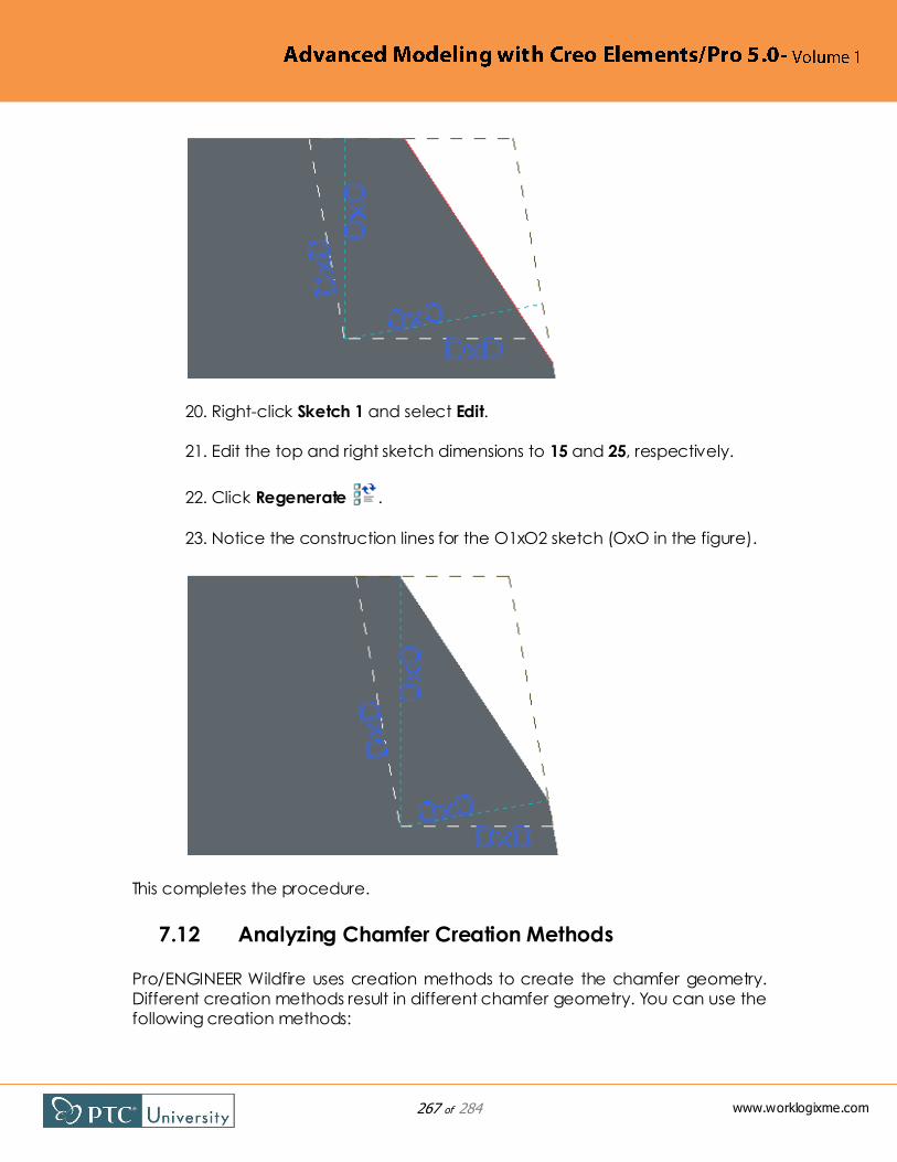
267 of 284
www.worklogixme.com
20. Right-click Sketch 1 and select Edit.
21. Edit the top and right sketch dimensions to 15 and 25, respectively.
22. Click Regenerate .
23. Notice the construction lines for the O1xO2 sketch (OxO in the figure).
This completes the procedure.
7.12 Analyzing Chamfer Creation Methods
Pro/ENGINEER Wildfire uses creation methods to create the chamfer geometry.
Different creation methods result in different chamfer geometry. You can use the
following creation methods:

268 of 284
www.worklogixme.com
Offset Surfaces — Determines the chamfer distance by offsetting the
neighboring surfaces of the reference edge. Pro/ENGINEER selects this
method by default. In the upper-right figure, the two surfaces were offset
by 30. At the intersection, two lines were extended perpendicular to each
surface. When the chamfer of distance value 30 is created in the lower-
left figure, it connect the two intersections of the surfaces and
perpendicular lines.
Tangent Distance — Determines the chamfer distance with vectors that
are tangent to the neighboring surfaces of the reference edge. In the
upper-right figure, two lines were extended tangent from the two
surfaces. Each line is of length 30 from the point of tangency to the other
line intersection. When the chamfer of distance value 30 is created in the
lower-right figure, it connects the two points of tangency.
Procedure: Analyzing Chamfer Creation Methods
Scenario
Analyze the chamfer creation methods in a part model.
Chamfer_Method chamfer_method.prt
Task 1. Analyze the chamfer creation methods in a part model.
1. Orient to the FRONT v iew orientation.
2. Right-click Sketch 1 and select Edit.
3. Notice that the surface offset distance and tangent line lengths are
both 30.
4. Orient to the Standard Orientation.
5. Start the Edge Chamfer Tool from the feature toolbar.
6. Select the upper-right edge.

269 of 284
www.worklogixme.com
7. Edit the O value to 30.
8. In the dashboard, select the Sets tab.
9. Notice that the chamfer distance is set at Offset Surfaces.
10. Click Complete Feature .
11. Orient to the FRONT v iew orientation.
12. Notice that the chamfer is at the ―Offset‖ construction lines' points of
intersection with the surfaces.
13. Edit the definition of Chamfer 1.
14. In the dashboard, select the Sets tab.
o Edit the distance drop-down list from Offset Surfaces to Tangent
Distance.
o Edit the D value to 30.
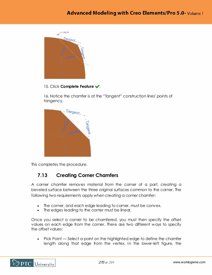
270 of 284
www.worklogixme.com
15. Click Complete Feature .
16. Notice the chamfer is at the ―Tangent‖ construction lines' points of
tangency.
This completes the procedure.
7.13 Creating Corner Chamfers
A corner chamfer removes material from the corner of a part, creating a
beveled surface between the three original surfaces common to the corner. The
following two requirements apply when creating a corner chamfer:
The corner, and each edge leading to corner, must be convex. The edges leading to the corner must be linear.
Once you select a corner to be chamfered, you must then specify the offset
values on each edge from the corner. There are two different ways to specify
the offset values:
Pick Point — Select a point on the highlighted edge to define the chamfer
length along that edge from the vertex. In the lower-left figure, the

271 of 284
www.worklogixme.com
chamfer length location was selected on each of the three edges. You
can always edit the chamfer to modify its offset values along each edge,
as shown in the lower-left figure.
Enter-input — Type a length dimension value. This value defines the
chamfer length along the highlighted edge from the vertex. The chamfer
in the lower-right figure was created by specifying a length dimension of
12 for each edge.
Procedure: Creating Corner Chamfers
Scenario
Create corner chamfers on a part model.
Corner_Chamfer corner_chamfer.prt
Task 1. Create a corner chamfer by selecting chamfer locations on edges.
1. Click Insert > Chamfer > Corner Chamfer from the main menu.
2. Select the main, upper-right 90 degree corner.
3. Select a location on the highlighted edge for the corner of the
chamfer.

272 of 284
www.worklogixme.com
4. Select a location on the other two highlighted edges.
5. Click OK from the Chamfer dialog box.
6. Right-click and select Edit to view the dimensions.

273 of 284
www.worklogixme.com
Task 2. Create a corner chamfer by specifying chamfer length dimensions on
edges.
1. Click Insert > Chamfer > Corner Chamfer.
2. Select the upper-right corner that is not 90 degrees.
3. In the menu manager, click Enter-input.
4. Type 12 as the length dimension and press ENTER.

274 of 284
www.worklogixme.com
5. Click Enter-input again from the menu manager and type 12 as the
length dimension and press ENTER.
6. Click Enter-input a third time from the menu manager and type 12 as
the length dimension and press ENTER.
7. Click OK from the Chamfer dialog box.
8. Right-click and select Edit to view the dimensions.
This completes the procedure.

275 of 284
www.worklogixme.com
7.14 Creating Chamfers by Reference
By default, when you create a chamfer, you must specify its distance
value. However, you can choose to use
a reference that defines the chamfer
size instead. You can specify a point,
vertex, or edge as the reference. The
system updates the geometry
automatically for any changes made
to the reference location. The lower-left
figure displays the resulting chamfer
geometry for the selected references. In the lower-right figure, the height of the
protrusion was decreased, and the datum point position used by the upper
chamfer has been moved. Notice that the resulting chamfer geometry updated
accordingly.
7.15 Analyzing Chamfer References and Pieces
By default, if you select an edge to be chamfered, and that selected edge has adjacent tangent edges, then the resulting chamfer automatically propagates
around those tangent edges. However, you can manipulate which edges are
ultimately chamfered by pressing SHIFT and using the Surface loop from to or
One-by-one selection options. These options enable you prevent the chamfer
from covering the whole tangent chain, allowing you to select only the edges
you want to receive the chamfer. In the upper figure, the edges were selected
using a Surface loop from to. The resulting geometry does not chamfer the top
three edges, even though they are tangent. When Surface loop from to
selection is used with the tool started, you can even select edges that are not
tangent.
Analyzing Chamfer Pieces
The Pieces tab in the dashboard enables you to further manipulate the chamfer. Using the Pieces tab you can perform the following functions:

276 of 284
www.worklogixme.com
Select a piece of the chamfer from the model to remove it.
Trim the chamfer by dragging the handles at the ends of the piece
inward so that less geometry is covered.
Extend the chamfer by dragging the handles at the ends of the piece
outward so that more geometry is covered.
If you want to trim or extend a closed-loop chamfer, simply remove a chamfer
piece from the chamfer first. This causes the handles to appear for trimming or
extending. In the lower figure, the bottom arc piece is excluded, which causes
the handles to display. The handles were used to trim the small corners so that
they were not chamfered, either.
To enter the functionality that enables you to select pieces to be removed, you
must select the piece in the Pieces tab. Once you have excluded or removed a
piece of the chamfer, the Pieces tab displays the piece as Edited. I f you want to
include all pieces again, you can edit the selected Piece drop-down list back to
Included.
If you need to terminate a chamfer other than at a chamfer piece,
you can use the Stop at Reference transition type.
7.16 Using Intent Edges for Chamfers
You can place a chamfer by selecting intent edges or intent surfaces. Using intent edges or surfaces makes selecting references quicker. They are also more
robust, preventing chamfers from failing when model changes are made, since
the references for the chamfers are tied to the features in the design model, not
the indiv idual edge references. In the upper figure, the chamfer is being created
by specifying the intent edges. In the lower figure, the post feature is moved to
the right, over a bump and into a gap. Though the resulting chamfer geometry
differs, the chamfer is still successful. Even when the post is updated from five
sides to four, the chamfer is still successful.
The following are examples of intent edges for a rectangular extrude coming
from a block:
The parallel outside edges of the extrude.
The end edges of the extrude.
The edges where the extrude meets the block.
So, for these examples, the shape of the rectangle is not important – only that an
extruded feature is present.

277 of 284
www.worklogixme.com
7.17 Using Chamfer Transitions
Transitions enable you to specify how the system handles overlapping or
discontinuous chamfer pieces.
Pro/ENGINEER uses default transitions that
are selected according to the particular
geometrical context. For many cases, you
can use the default transitions. Sometimes,
however, you need to modify the existing
transitions to achieve the preferred
chamfer geometry.
To access Transition mode, you can either
click Transition Mode in the dashboard
or right-click and select Show transitions
while using the Chamfer tool. To exit
Transition mode, you can either click Set
Mode in the dashboard, or right-click and select Back to sets.
Chamfer Transition Types
When you access Transition mode, the system displays all of the available
chamfer transitions, as shown in the upper-right figure. When you select an
available transition, the dashboard displays the currently set type for that
transition in the Transition Type drop-down list. The drop-down list contains valid
transition types available for the currently selected transition, based on the
geometrical context. You can change the transition type for the currently
selected transition. The following is a list of chamfer transition types (note that not
all transition types listed are available for a given context):
Default — Pro/ENGINEER determines the transition type that is the best fit
for the geometrical context. The transition type used for the default
appears in parenthesis.
Intersect — Extends two or more overlapping chamfer pieces toward
each other until they merge, forming a sharp boundary.
Patch — Creates a patched surface at the location where three or four
chamfer pieces overlap. Optionally, you can specify a surface on which
to place a fillet, and specify the fillet radius to be used.
Corner Plane — Chamfers the corner transition formed by overlapping
three chamfer pieces with a plane.
Stop at Reference — Terminates chamfer geometry at the selected
datum point or datum plane. You must specify the reference to be used.
Blend — Creates a fillet surface between the chamfer pieces using an
edge reference.

278 of 284
www.worklogixme.com
Continue — Extends chamfer geometry into two chamfer pieces.
Stop Case 1 — Terminates the chamfer using geometry configured by
Pro/ENGINEER.
Procedure: Using Chamfer Transitions
Scenario
Specify different chamfer transitions in a part model.
Chamfer_Transitions chamfer_trans.prt
Task 1. Specify different chamfer transitions in a part model.
1. Start the Edge Chamfer Tool from the feature toolbar.
2. Press CTRL and select the front three edges.
3. Edit the D value to 2.
4. Right-click and select Add set.
5. Press CTRL and select the two parallel edges.
6. Edit the D value to 2.

279 of 284
www.worklogixme.com
7. In the dashboard, click Transition Mode .
8. Select the upper, three-way corner transition.
9. In the dashboard, notice that the default transition type is Intersect.
10. Select the lower, three-way corner transition.
11. In the dashboard, notice that the default transition type is Corner
Plane. This corner has a different geometry case than the prev iously
selected corner.
12. Click Preview Feature .

280 of 284
www.worklogixme.com
13. Click Resume Feature .
14. Select the upper three-way transition and edit its type to Corner Plane.
15. Click Complete Feature .
16. Start the Edge Chamfer Tool .
17. Select the upper-right edge.
18. Edit the D value to 2.

281 of 284
www.worklogixme.com
19. Right-click and select Show transitions.
20. Notice that there are no corner transitions.
21. Right-click and select Back to sets.
22. Drag the D value to 4.
23. In the dashboard, click Transition Mode .
24. Select the corner transition and edit its type to Patch in the dashboard.
25. Click Preview Feature .

282 of 284
www.worklogixme.com
26. Click Resume Feature .
27. Click in the Optional surface collector and select the top surface.
28. Edit the Radius to 2 in the dashboard.
29. Click Complete Feature .
This completes the procedure.

283 of 284
www.worklogixme.com
Check Your Knowledge
1. In the model shown, you want to change the shape of protrusion "B" to a
hexagon but the bottom edges of the protrusion have been rounded. Which
round reference type will accommodate this change and NOT cause failing
features?
A - Surface to Surface
B - One-by-One
C - Intent chain
D - Regardless of which round reference type you use, the Round feature
will fail.
2. Corner chamfers can be created using which option(s)?
A - Chamfer tool
B - Insert pull-down menu
C - A or B
3. True or False? It is possible to define sets and transitions for chamfers.
A - True
B - False
4. Which dimension schemes are valid for creating chamfers?
A - Angle X D
B - D1 X D2
C - O1 X O2
D - All of the above
E - None of the above

284 of 284
www.worklogixme.com
5. What method enables you to terminate the round geometry at a specific
datum point?
A - Extend option
B - Trim option
C - Stop at Reference transition
D - Patch transition
E - None of the above