Embed Size (px)
Citation preview

For Info go to www.aws.org/ad-index
F
________________________________________
_______________For Info go to www.aws.org/ad-index
| | | | | |Previous Page Contents Zoom in Zoom out Front Cover Search Issue Next PageLWE DINGJournalJournal BA
M SaGEF
| | | | | |Previous Page Contents Zoom in Zoom out Front Cover Search Issue Next PageLWE DINGJournalJournal BA
M SaGEF
________________________________________
_______________
| | | | | |Previous Page Contents Zoom in Zoom out Front Cover Search Issue Next PageLWE DINGJournalJournal BA
M SaGEF
| | | | | |Previous Page Contents Zoom in Zoom out Front Cover Search Issue Next PageLWE DINGJournalJournal BA
M SaGEF
LWE DINGJournalJournal
We Need Your Response
Today you are the recipient of the digital Welding Journal, and we hope
you will enjoy all its added benefits.
l Timely delivery
l Searchable
l Active links to welding information
l Archiveable
l Environmentally friendly
We want to make the delivery of the Welding Journal as pleasant and
trouble-free as possible. Please take a few moments to complete a ver y
short survey so we can know how the experience is for you, and what
ways we can improve it, if need be. Please click on the link to take you to
the sur vey. Thanks for your time and enjoy the Welding Journal.
PUBLISHED BY THE AMERICAN WELDING SOCIETY TO ADVANCE THE SCIENCE, TECHNOLOGY, AND APPLICATION OF WELDINGAND ALLIED JOINING AND CUTTING PROCESSES, INCLUDING BRAZING, SOLDERING, AND THERMAL SPRAYING
January 2009
•Tips for Good Gas Metal Arc Welds
•Welding Technology Abounds at the2008 EExxppoossiittiioonn
••IImmpprroovveedd BBooiilleerr TTuubbee CCllaaddddiinngg wwiitthhGGMMAAWW--PP
Contents | Zoom in | Zoom out Search Issue | Next PageFor navigation instructions please click here
Contents | Zoom in | Zoom out Search Issue | Next PageFor navigation instructions please click here
For Info go to www.aws.org/ad-index
| | | | | |Previous Page Contents Zoom in Zoom out Front Cover Search Issue Next PageLWE DINGJournalJournal BA
M SaGEF
| | | | | |Previous Page Contents Zoom in Zoom out Front Cover Search Issue Next PageLWE DINGJournalJournal BA
M SaGEF
______________
_______________
For Info go to www.aws.org/ad-index
| | | | | |Previous Page Contents Zoom in Zoom out Front Cover Search Issue Next PageLWE DINGJournalJournal BA
M SaGEF
| | | | | |Previous Page Contents Zoom in Zoom out Front Cover Search Issue Next PageLWE DINGJournalJournal BA
M SaGEF
___________________
______________
_____________________

For Info go to www.aws.org/ad-index______________________
| | | | | |Previous Page Contents Zoom in Zoom out Front Cover Search Issue Next PageLWE DINGJournalJournal BA
M SaGEF
| | | | | |Previous Page Contents Zoom in Zoom out Front Cover Search Issue Next PageLWE DINGJournalJournal BA
M SaGEF
_____________________
______________
________________
3WELDING JOURNAL
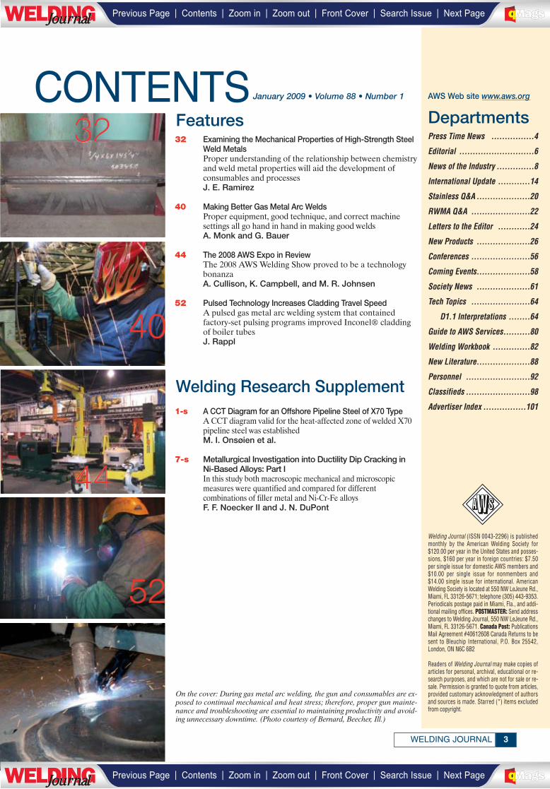
CONTENTS32 Examining the Mechanical Properties of High-Strength Steel
Weld MetalsProper understanding of the relationship between chemistryand weld metal properties will aid the development ofconsumables and processesJ. E. Ramirez
40 Making Better Gas Metal Arc WeldsProper equipment, good technique, and correct machinesettings all go hand in hand in making good weldsA. Monk and G. Bauer
44 The 2008 AWS Expo in ReviewThe 2008 AWS Welding Show proved to be a technologybonanzaA. Cullison, K. Campbell, and M. R. Johnsen
52 Pulsed Technology Increases Cladding Travel SpeedA pulsed gas metal arc welding system that containedfactory-set pulsing programs improved Inconel® claddingof boiler tubesJ. Rappl
Welding Journal (ISSN 0043-2296) is publishedmonthly by the American Welding Society for$120.00 per year in the United States and posses-sions, $160 per year in foreign countries: $7.50per single issue for domestic AWS members and$10.00 per single issue for nonmembers and$14.00 single issue for international. AmericanWelding Society is located at 550 NW LeJeune Rd.,Miami, FL 33126-5671; telephone (305) 443-9353.Periodicals postage paid in Miami, Fla., and addi-tional mailing offices. POSTMASTER: Send addresschanges to Welding Journal, 550 NW LeJeune Rd.,Miami, FL 33126-5671. Canada Post: PublicationsMail Agreement #40612608 Canada Returns to besent to Bleuchip International, P.O. Box 25542,London, ON N6C 6B2
Readers of Welding Journal may make copies ofarticles for personal, archival, educational or re-search purposes, and which are not for sale or re-sale. Permission is granted to quote from articles,provided customary acknowledgment of authorsand sources is made. Starred (*) items excludedfrom copyright.
DepartmentsPress Time News ................4
Editorial ............................6
News of the Industry ..............8
International Update ............14
Stainless Q&A ....................20
RWMA Q&A ......................22
Letters to the Editor ............24
New Products ....................26
Conferences ......................56
Coming Events....................58
Society News ....................61
Tech Topics ......................64
D1.1 Interpretations ........64
Guide to AWS Services..........80
Welding Workbook ..............82
New Literature....................88
Personnel ........................92
Classifieds ........................98
Advertiser Index ................1011-s A CCT Diagram for an Offshore Pipeline Steel of X70 TypeA CCT diagram valid for the heat-affected zone of welded X70pipeline steel was establishedM. I. Onsøien et al.
7-s Metallurgical Investigation into Ductility Dip Cracking inNi-Based Alloys: Part IIn this study both macroscopic mechanical and microscopicmeasures were quantified and compared for differentcombinations of filler metal and Ni-Cr-Fe alloysF. F. Noecker II and J. N. DuPont
Features
Welding Research Supplement
32
40
44
52
January 2009 • Volume 88 • Number 1 AWS Web site www.aws.org
On the cover: During gas metal arc welding, the gun and consumables are ex-posed to continual mechanical and heat stress; therefore, proper gun mainte-nance and troubleshooting are essential to maintaining productivity and avoid-ing unnecessary downtime. (Photo courtesy of Bernard, Beecher, Ill.)
| | | | | |Previous Page Contents Zoom in Zoom out Front Cover Search Issue Next PageLWE DINGJournalJournal BA
M SaGEF
| | | | | |Previous Page Contents Zoom in Zoom out Front Cover Search Issue Next PageLWE DINGJournalJournal BA
M SaGEF
_________
PRESS TIMENEWS
NTSB Reaches Decision on I-35W Bridge Collapse
The National Transportation Safety Board (NTSB), Washington, D.C., recently determined the probable cause of the I-35W bridge’s collapse in Minneapolis, Minn.,was the inadequate load capacity, due to a design error by Sverdrup & Parcel and Asso-ciates, Inc., of the gusset plates at the U10 nodes. These failed under a combination ofsubstantial increases in the weight of the bridge, which resulted from previous modifica-tions, and the traffic and concentrated construction loads on the bridge on the day ofthe accident.
“We believe this thorough investigation should put to rest any speculation as to theroot cause of this terrible accident and provide a roadmap for improvements to preventfuture tragedies,” said NTSB Acting Chairman Mark V. Rosenker. “We came to thisconclusion only through exhaustive efforts to eliminate each potential area that mighthave caused or contributed to this accident.”
On August 1, 2007, the eight-lane, 1907-ft-long I-35W highway bridge over the Mis-sissippi River experienced a catastrophic failure in the main span of the deck truss. Onethousand feet of the deck truss collapsed, with about 456 ft of the main span falling 108ft into the 15-ft-deep river.
The failure of Sverdrup & Parcel’s quality control procedures to ensure the appro-priate main truss gusset plate calculations were performed for the I-35W bridge and in-adequate design review by federal and state transportation officials contributed to this;so did the generally accepted practice among federal and state transportation officialsof giving inadequate attention to gusset plates during inspections for conditions of dis-tortion and excluding gusset plates in load rating analysis.
The NTSB, as a result of its investigation, made nine recommendations to the Fed-eral Highway Administration and the American Association of State Highway and Trans-portation Officials dealing with improving bridge design review procedures, bridge inspection procedures, bridge inspection, training, and load rating evaluations.
Outlook Given for Metal Forming and Fabricating Industry
In a survey by management consulting firm Homburg & Partner, Cambridge, Mass.,201 U.S. companies in the metal forming and fabricating industry were asked to give a2009/2010 outlook on market development and specify key success factors.
Innovation came in as the top key success factor for the next three years by morethan 25% of the surveyed companies. Efficient automation is the imperative goal whendealing with production costs and process management, which considered together formthe most important key factors for 30% of the participants. Also, nearly 15% of the sur-veyed companies see expanding into global markets as the key success factor.
In the United States, industry’s growth is estimated as 7% in 2009 and 10% in 2010and worldwide as 12% in 2009 and 15% in 2010. About one-third concur the U.S. finan-cial crisis will not render into a cash flow problem, yet it is commonly agreed this has anegative effect on growth rates for the metal forming and fabricating market. The auto-motive producers crisis is seen as a threat, too, but management perceives it less critically.
The firm’s in-depth discussions have shown top management of market leaders pre-dominantly disagree with the highly positive growth rates of U.S. markets, however, andinstead expect they will stay flat or perhaps increase slightly positive with up to 2% in2009, depending on the regarded segment.
ESAB Receives Major Wind Energy Industry Order
ESAB Welding & Cutting Products has made its largest ever, single-customer orderfor welding and cutting equipment and consumables. Wind tower manufacturer VestasTowers A/S, a part of Vestas Wind Systems A/S, placed the multimillion dollar purchase.
This complete equipment and consumables package will be supplied. In addition,the full order comprises automated cutting equipment manufactured by the company inFlorence, S.C.; heavy automation welding equipment manufactured by it in Sweden;and positioning and handling equipment supplied by its newly acquired facility in Singa-pore. The column and boom equipment will include ESAB’s latest telescopictechnology. Also, the company is well positioned to supply the welding consumablesonce the wind tower factory comes into production.
During 2009, the full equipment package will be delivered and installed.
JANUARY 20094
MEMBER
Publisher Andrew Cullison
Publisher Emeritus Jeff Weber
EditorialEditorial Director Andrew Cullison
Editor Mary Ruth JohnsenAssociate Editor Howard M. Woodward
Associate Editor Kristin CampbellPeer Review Coordinator Erin Adams
Graphics and Production Production Manager Zaida Chavez
Senior Production Coordinator Brenda Flores
AdvertisingNational Sales Director Rob Saltzstein
Advertising Sales Representative Lea Garrigan BadwyAdvertising Production Manager Frank Wilson
SubscriptionsSubscriptions Representative Edalia Suarez
American Welding Society550 NW LeJeune Rd., Miami, FL 33126
(305) 443-9353 or (800) 443-9353
Publications, Expositions, Marketing CommitteeD. L. Doench, ChairHobart Brothers Co.
T. A. Barry, Vice ChairMiller Electric Mfg. Co.J. D. Weber, Secretary
American Welding SocietyP. Baka, The Lincoln Electric Co.
S. Bartholomew, ESAB Welding & Cutting Prod.D. Brown, Weiler BrushJ. Deckrow, Hypertherm
D. DeCorte, RoMan Mfg.J. Dillhoff, OKI Bering
J. R. Franklin, Sellstrom Mfg. Co.D. Levin, Airgas
J. Mueller, Thermadyne IndustriesR. G. Pali, J. P. Nissen Co.
J. F. Saenger Jr., ConsultantS. Smith, Weld-Aid ProductsD. Wilson, Wilson Industries
J. C. Bruskotter, Ex Off., Bruskotter Consulting ServicesH. Castner, Ex Off., Edison Welding Institute
L. G. Kvidahl, Ex Off., Northrup Grumman Ship SystemsG. E. Lawson, Ex Off., ESAB Welding & Cutting Prod.
E. C. Lipphardt, Ex Off., ConsultantS. Liu, Ex Off., Colorado School of Mines
E. Norman, Ex Off., Southwest Area Career CenterR. W. Shook, Ex Off., American Welding Society
Copyright © 2009 by American Welding Society in both printed and electronic formats. The Society is not responsible for any statement madeor opinion expressed herein. Data and information developed by the au-thors of specific articles are for informational purposes only and are notintended for use without independent, substantiating investigation on thepart of potential users.
________
| | | | | |Previous Page Contents Zoom in Zoom out Front Cover Search Issue Next PageLWE DINGJournalJournal BA
M SaGEF
| | | | | |Previous Page Contents Zoom in Zoom out Front Cover Search Issue Next PageLWE DINGJournalJournal BA
M SaGEF

For Info go to www.aws.org/ad-index
| | | | | |Previous Page Contents Zoom in Zoom out Front Cover Search Issue Next PageLWE DINGJournalJournal BA
M SaGEF
| | | | | |Previous Page Contents Zoom in Zoom out Front Cover Search Issue Next PageLWE DINGJournalJournal BA
M SaGEF
__________________________________
______________
EDITORIAL
I’d like to extend my best wishes to all of you in this new year, the 90th year for AWS.I hope everyone had a wonderful holiday season and that 2009 will bring with it newopportunities for each of us.
At this time of year it is natural to set goals. We all have them, both personal and pro-fessional. For many of us, our personal goals begin with a set of New Year’s resolutions.We all need to have our sights set on achieving a result for the year whether it be losingsome weight, getting more exercise, buying a new car, or accomplishing some repairsaround the house. The list can be quite long.
In addition, most of us also have professional goals, either those we set for ourselvesor, most likely, goals that are requirements from our employer. Companies have goalsset by their boards of directors, committees, and other management entitites. TheAmerican Welding Society is similar to the rest of corporate America in that it too setsgoals. Some are set by the Finance Committee, some by our Compensation Committee,and some are set by the Board of Directors. Goal setting is the thing that actually putsus on a course or direction to being successful.
During my address at the AWS Annual Meeting in Las Vegas this past October, I list-ed four major areas of growth for AWS: Welding Education, Career Expansion,Technology Support, and Membership Attraction.
Welding Education includes both individuals getting into the profession at some levelthrough education and training, and improving the awareness and pride of our profes-sion by those outside of it, such as government and educational entities.
Career Expansion means growing in experience and knowledge or specializing one’straining.
Technology Support occurs when the profession’s infrastructure responds to thechanges in the demand from the field applications. A lot of new designs and other devel-opments occur when the old way of doing things or the processes and materials used willno longer do the job. Necessity has always been the catalyst for change.
Membership Attraction will occur when AWS is successful in the first three areas.These four areas are generalized versions of goals that are part of the overall strate-
gic plan for AWS.During my talk at the Annual Meeting, I closed with a challenge to every person in
attendance there and I now offer you all the same challenge: Bring one new person intothe welding profession. I ask you to mentor, train, or counsel a neighbor, son or daugh-ter, nephew or niece, a friend of a friend, or a kid who lives on your street. Help them tomake a career goal that includes options within the welding profession. We need newpeople in every discipline related to welding: electrical engineers, mechanical engineers,metallurgists, welding engineers, computer programmers, welders, ironworkers, sheet-metal workers, boilermakers, pipeline welders. The list goes on and on. We need peopleto design and manufacture welding equipment and consumables as well as those who willuse them. We also need people to set the standards and regulations used for the profes-sion. From the earliest times, mankind has been building things. Welding lets us buildbigger and better.
Goals are only an indication of what we want to accomplish; it takes a plan and hardwork to make them happen. I am happy to report that our membership will hit the 55,000
mark very soon if it has not already by the time youreceive this editorial. That is an indicator that we aresucceeding in some of our goals. Together we can growthe infrastructure of AWS.
I plan to speak at many AWS Sections this year,and I know I’ll get the opportunity to hear many suc-cess stories. Please share those stories with the entireAWS membership by sending in your monthly meetingreports to the Welding Journal.
In the meantime, I hope you all have a great year.
JANUARY 20096
Founded in 1919 to Advance the Science,Technology and Application of Welding
Setting Goals and MakingThem Happen
Victor Y. MatthewsAWS President
OfficersPresident Victor Y. Matthews
The Lincoln Electric Co.
Vice President John C. BruskotterBruskotter Consulting Services, LLC
Vice President John L. MendozaCPS Energy
Vice President William A. Rice Jr.OKI Bering
Treasurer Earl C. LipphardtConsultant
Executive Director Ray W. ShookAmerican Welding Society
DirectorsB. P. Albrecht (At Large), Miller Electric Mfg. Co.
J. R. Bray (Dist. 18), Affiliated Machinery, Inc.
H. R. Castner (At Large), Edison Welding Institute
D. B. DeCorte (At Large), RoMan Mfg. Inc.
G. Fairbanks (Dist. 9), Fairbanks Inspection & Testing Services
D. A. Flood (Dist. 22), Tri Tool, Inc.
M. V. Harris (Dist. 15), Valley National Gases
R. A. Harris (Dist. 10), Consultant
D. C. Howard (Dist. 7), Concurrent Technologies Corp.
J. Jones (Dist. 17), Thermadyne
W. A. Komlos (Dist. 20), ArcTech LLC
D. Landon (Dist. 16), Vermeer Mfg. Co.
R. C. Lanier (Dist. 4), Pitt C.C.
G. E. Lawson (Past President), ESAB Welding & Cutting Prod.
J. Livesay (Dist. 8), Tennessee Technology Center
D. L. McQuaid (At Large), DL McQuaid & Associates
S. Mattson (Dist. 5), Mattson Repair Service
S. P. Moran (Dist. 12), Miller Electric Mfg. Co.
R. L. Norris (Dist. 1), Consultant
T. C. Parker (Dist. 14), Miller Electric Mfg. Co.
K. A. Phy (Dist. 6), Entergy Nuclear Operations, Inc.
W. R. Polanin (Dist. 13), Illinois Central College
N. Saminich (Dist. 21), Ninyo & Moore
N. S. Shannon (Dist. 19), Carlson Testing of Portland
T. A. Siewert (At Large), NIST
E. Siradakis (Dist. 11), Airgas Great Lakes
K. R. Stockton (Dist. 2), PSE&G, Maplewood Testing Serv.
G. D. Uttrachi (Past President), WA Technology, LLC
D. R. Wilson (At Large), Wilson Industries
M. R. Wiswesser (Dist. 3), Welder Training & Testing Institute
| | | | | |Previous Page Contents Zoom in Zoom out Front Cover Search Issue Next PageLWE DINGJournalJournal BA
M SaGEF
| | | | | |Previous Page Contents Zoom in Zoom out Front Cover Search Issue Next PageLWE DINGJournalJournal BA
M SaGEF
For Info go to www.aws.org/ad-index
F
_____________
_______
______________
| | | | | |Previous Page Contents Zoom in Zoom out Front Cover Search Issue Next PageLWE DINGJournalJournal BA
M SaGEF
| | | | | |Previous Page Contents Zoom in Zoom out Front Cover Search Issue Next PageLWE DINGJournalJournal BA
M SaGEF
JANUARY 20098
NEWS OF THEINDUSTRY
Exhibition Supporting the WeldingProfession Goes Successfully
The first-ever “Where Are the Welders?” Instructional Forumand Career Fair attracted more than 40 high school students andparents at the Spencer High School Industrial Tech building inSpencer, Iowa, on Nov. 10. Career possibilities in industrial tech-nology were shown during the three-hour event to students inBuena Vista, Clay, Dickinson, and Emmet counties.
“What a great way for area employers to connect with Corri-dor students who have a passion for welding as well as metal fab-rication and machining,” said Shaun Arneson, vice president,Iowa Lakes Corridor Development Corp. This agency hosted theforum and fair, part of its workforce initiative, that let weldinginstructors, employers, and local manufacturers share their in-sights on the welding and fabrication industries.
Involvement consisted of more than 12 area employers.Demonstrations included a wire weld demo by John Tatman,Maurer Manufacturing, and Chris McKay, Airgas North Cen-tral, as well as a robotic weld demo by Northwest Iowa Commu-nity College. In addition, Jeff Merryman of Employment Con-nections, Inc., spoke on the topic of “Job Seeking Skills”; JamieSlipke of Rosenboom Machine & Tool, Inc., presented “Weldingas a Career”; and Jeff Steiner of Polaris Industries, Inc., discussedand demonstrated “Welding Technologies and Automation.”
The employers/instructors and students who attended pro-vided an evaluation overall rating of 91% and 92%, respectively.
DMI Industries Increases Production to Meet Wind Energy Demands
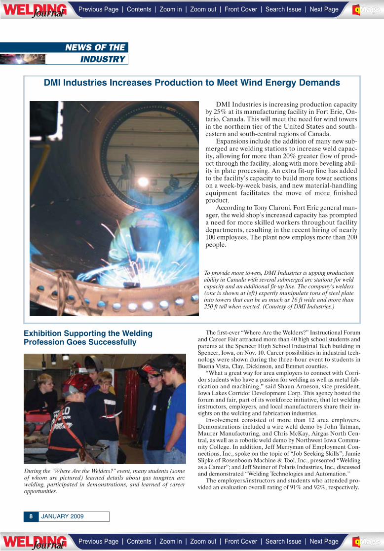
DMI Industries is increasing production capacityby 25% at its manufacturing facility in Fort Erie, On-tario, Canada. This will meet the need for wind towersin the northern tier of the United States and south-eastern and south-central regions of Canada.
Expansions include the addition of many new sub-merged arc welding stations to increase weld capac-ity, allowing for more than 20% greater flow of prod-uct through the facility, along with more beveling abil-ity in plate processing. An extra fit-up line has addedto the facility’s capacity to build more tower sectionson a week-by-week basis, and new material-handlingequipment facilitates the move of more finished product.
According to Tony Claroni, Fort Erie general man-ager, the weld shop’s increased capacity has prompteda need for more skilled workers throughout facilitydepartments, resulting in the recent hiring of nearly100 employees. The plant now employs more than 200people.
To provide more towers, DMI Industries is upping productionability in Canada with several submerged arc stations for weldcapacity and an additional fit-up line. The company’s welders(one is shown at left) expertly manipulate tons of steel plateinto towers that can be as much as 16 ft wide and more than250 ft tall when erected. (Courtesy of DMI Industries.)
During the “Where Are the Welders?” event, many students (someof whom are pictured) learned details about gas tungsten arc welding, participated in demonstrations, and learned of career opportunities.
| | | | | |Previous Page Contents Zoom in Zoom out Front Cover Search Issue Next PageLWE DINGJournalJournal BA
M SaGEF
| | | | | |Previous Page Contents Zoom in Zoom out Front Cover Search Issue Next PageLWE DINGJournalJournal BA
M SaGEF
9WELDING JOURNAL
FABTECH International & AWS WeldingShow Honored by Tradeshow Week
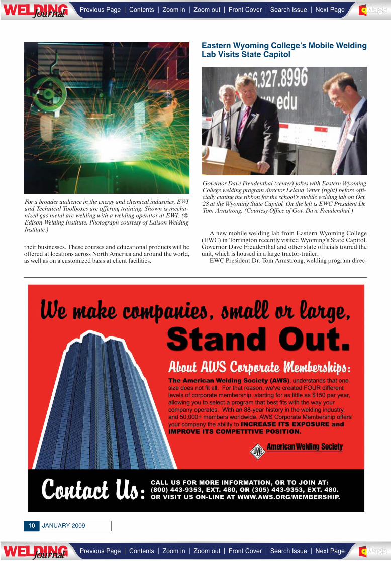
Tradeshow Week (TSW), the global exhibition industry news-magazine, recently named the FABTECH International & AWSWelding Show as a 2008 TSW Fastest 50 winner. The fifty fastest-growing shows in North America, based on total net squarefootage growth and percentage of growth between 2005 and 2007,were honored. During this time, the FABTECH International &AWS Welding Show grew more than 37% from 336,795 net sq ftand 783 exhibitors to 461,627 net sq ft and 1007 exhibitors.
Friction Stir Welding Project Gets Supportfrom the Department of Energy
Oak Ridge National Laboratory (ORNL) technologies to im-prove energy efficiency in industry, including flexible hybrid fric-tion stir joining, have won funding from the Department of En-ergy’s Industrial Technologies Program. These will bring $7.5 mil-lion to ORNL and another $3 million to industry partners.
Transforming friction stir welding (FSW) into a mainstreamprocess is one of the projects. Researchers hope to develop newmaterials for FSW tools, hybrid friction stir welding with auxil-iary heating to reduce forge load, and multipass multilayer tech-nology for very thick sections. Ultimately, this will result in afield-deployable system providing flexibility and affordability foron-site construction. Initial applications will be for large oil andgas pipelines. Partners are as follows: Exxon Mobil Corp., ESABGroup, MegaStir Technologies, and Edison Welding Institute.
Edison Welding Institute and TechnicalToolboxes Provide Training Together
The Edison Welding Institute (EWI), Columbus, Ohio, andTechnical Toolboxes Inc. have executed a joint agreement to ad-vance training and education within the energy and chemical in-dustries. The organizations will immediately begin offering or-ganized training. Continuing education units will be offered bythe programs, allowing attendees to obtain partial college creditfor the courses while learning skills and technology crucial to
This award pays tribute to the FABTECH International & AWSWelding Show’s square footage and exhibitor growth.
For info go to www.aws.org/ad-index
___________
| | | | | |Previous Page Contents Zoom in Zoom out Front Cover Search Issue Next PageLWE DINGJournalJournal BA
M SaGEF
| | | | | |Previous Page Contents Zoom in Zoom out Front Cover Search Issue Next PageLWE DINGJournalJournal BA
M SaGEF
___________________
______________
JANUARY 200910
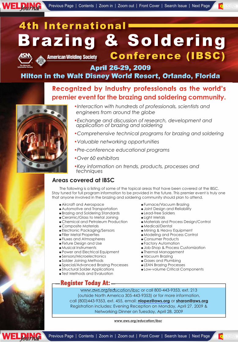
their businesses. These courses and educational products will beoffered at locations across North America and around the world,as well as on a customized basis at client facilities.
Eastern Wyoming College’s Mobile WeldingLab Visits State Capitol
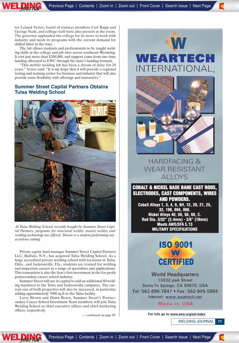
A new mobile welding lab from Eastern Wyoming College(EWC) in Torrington recently visited Wyoming’s State Capitol.Governor Dave Freudenthal and other state officials toured theunit, which is housed in a large tractor-trailer.
EWC President Dr. Tom Armstrong, welding program direc-
For a broader audience in the energy and chemical industries, EWIand Technical Toolboxes are offering training. Shown is mecha-nized gas metal arc welding with a welding operator at EWI. (©Edison Welding Institute. Photograph courtesy of Edison WeldingInstitute.)
Governor Dave Freudenthal (center) jokes with Eastern WyomingCollege welding program director Leland Vetter (right) before offi-cially cutting the ribbon for the school’s mobile welding lab on Oct.28 at the Wyoming State Capitol. On the left is EWC President Dr.Tom Armstrong. (Courtesy Office of Gov. Dave Freudenthal.)
| | | | | |Previous Page Contents Zoom in Zoom out Front Cover Search Issue Next PageLWE DINGJournalJournal BA
M SaGEF
| | | | | |Previous Page Contents Zoom in Zoom out Front Cover Search Issue Next PageLWE DINGJournalJournal BA
M SaGEF
_________________________
11WELDING JOURNAL
tor Leland Vetter, board of trustees members Carl Rupp andGeorge Nash, and college staff were also present at the event.The governor applauded the college for its move to work withindustry and mesh its programs with the current demand forskilled labor in the state.
The lab allows students and professionals to be taught weld-ing skills at the college and job sites across southeast Wyoming.It cost just more than $200,000, and support came from one-timefunding allocated to EWC through the state’s funding formula.
“This mobile welding lab has been a dream of mine for 20years,” Vetter said. “It is my hope that it will provide a regionaltesting and training center for business and industry that will alsoprovide some flexibility with offerings and instructors.”
Summer Street Capital Partners ObtainsTulsa Welding School
Private equity fund manager Summer Street Capital PartnersLLC, Buffalo, N.Y., has acquired Tulsa Welding School. As alarge accredited private welding school with locations in Tulsa,Okla., and Jacksonville, Fla., students are trained for weldingand inspection careers in a range of specialties and applications.This transaction is also the firm’s first investment in the for-profitpostsecondary career school industry.
Summer Street will use its capital to add an additional 80 weld-ing machines to the Tulsa and Jacksonville campuses. The cur-rent size of both properties will also be increased, in particularadding approximately 7000 sq ft to the Tulsa facility.
Larry Brown and Dawn Bravo, Summer Street’s Postsec-ondary Career School Investment Team members, will join TulsaWelding School as chief executive officer and chief marketingofficer, respectively.
For info go to www.aws.org/ad-index
At Tulsa Welding School, recently bought by Summer Street Capi-tal Partners, programs for structural welder, master welder, andwelding technology are offered. Shown is a student performing oxy-acetylene cutting.
— continued on page 89
| | | | | |Previous Page Contents Zoom in Zoom out Front Cover Search Issue Next PageLWE DINGJournalJournal BA
M SaGEF
| | | | | |Previous Page Contents Zoom in Zoom out Front Cover Search Issue Next PageLWE DINGJournalJournal BA
M SaGEF
______________
_______________
•Interaction with hundreds of professionals, scientists andengineers from around the globe
•Exchange and discussion of research, development andapplication of brazing and soldering
•Comprehensive technical programs for brazing and soldering
•Valuable networking opportunities
•Pre-conference educational programs
•Over 60 exhibitors
•Key information on trends, products, processes andtechniques
Recognized by industry professionals as the world’spremier event for the brazing and soldering community.
�Aircraft and Aerospace�Automotive and Transportation� Brazing and Soldering Standards�Ceramic/Glass to Metal Joining�Chemical and Petroleum Production�Composite Materials� Electronic Packaging/Sensors� Filler Metal Properties� Fluxes and Atmospheres� Fixture Design and Use�Musical Instruments� Power and Electrical Equipment� Sensors/Microelectronics� Solder Joining Methods� Special/Advanced Brazing Processes� Structural Solder Applications� Test Methods and Evaluation
� Furnace/Vacuum Brazing� Joint Design and Reliability� Lead-free Solders� Light Metals�Materials and Process Design/Control�Medical/Dental�Mining & Heavy Equipment�Modeling and Process Control�Consumer Products� Factory Automation� Job-Shop & Process Customization� Thermal Management�Vacuum Brazing�Gases and Plumbing� LEAN Brazing Processes� Low-volume Critical Components
Areas covered at IBSCThe following is a listing of some of the topical areas that have been covered at the IBSC.
Stay tuned for full program information to be provided in the future. This premier event is truly onethat anyone involved in the brazing and soldering community should plan to attend.
www.aws.org/education/ibsc or call 800-443-9353, ext. 213(outside North America 305-443-9353) or for more information,
call (800)443-9353, ext. 455, email: [email protected] or [email protected] includes: Evening Reception on Monday, April 27, 2009 &
Networking Dinner on Tuesday, April 28, 2009
April 26-29, 2009Hilton in the Walt Disney World Resort, Orlando, Florida
4th International
Brazing & SolderingConference (IBSC)
www.aws.org/education/ibsc
Register Today At:
__________________________
| | | | | |Previous Page Contents Zoom in Zoom out Front Cover Search Issue Next PageLWE DINGJournalJournal BA
M SaGEF
| | | | | |Previous Page Contents Zoom in Zoom out Front Cover Search Issue Next PageLWE DINGJournalJournal BA
M SaGEF
________________________
____________________
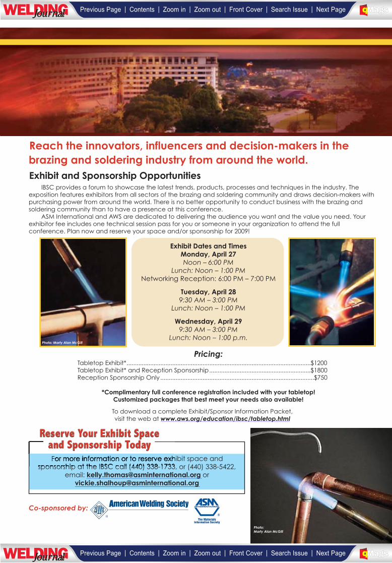
Exhibit and Sponsorship OpportunitiesIBSC provides a forum to showcase the latest trends, products, processes and techniques in the industry. The
exposition features exhibitors from all sectors of the brazing and soldering community and draws decision-makers withpurchasing power from around the world. There is no better opportunity to conduct business with the brazing andsoldering community than to have a presence at this conference.
ASM International and AWS are dedicated to delivering the audience you want and the value you need. Yourexhibitor fee includes one technical session pass for you or someone in your organization to attend the fullconference. Plan now and reserve your space and/or sponsorship for 2009!
Exhibit Dates and TimesMonday, April 27Noon – 6:00 PM
Lunch: Noon – 1:00 PMNetworking Reception: 6:00 PM – 7:00 PM
Tuesday, April 289:30 AM – 3:00 PM
Lunch: Noon – 1:00 PM
Wednesday, April 299:30 AM – 3:00 PM
Lunch: Noon – 1:00 p.m.
Pricing:Tabletop Exhibit*.............................................................................................................$1200Tabletop Exhibit* and Reception Sponsorship............................................................$1800Reception Sponsorship Only...........................................................................................$750
*Complimentary full conference registration included with your tabletop!Customized packages that best meet your needs also available!
To download a complete Exhibit/Sponsor Information Packet,visit the web at www.aws.org/education/ibsc/tabletop.html
Reach the innovators, influencers and decision-makers in thebrazing and soldering industry from around the world.
For more information or to reserve exhibit space andsponsorship at the IBSC call (440) 338-1733, or (440) 338-5422,
email: [email protected] [email protected]
Reserve Your Exhibit Spaceand Sponsorship Today
Co-sponsored by:
Photo: Marty Alan McGill
Photo:Marty Alan McGill
_______________________________
____________________________
| | | | | |Previous Page Contents Zoom in Zoom out Front Cover Search Issue Next PageLWE DINGJournalJournal BA
M SaGEF
| | | | | |Previous Page Contents Zoom in Zoom out Front Cover Search Issue Next PageLWE DINGJournalJournal BA
M SaGEF
________________________________

INTERNATIONALUPDATE
Valmet Automotive and Fisker Automotiveto Build Hybrid Sports Car in Finland
Valmet Automotive, Helsinki, Finland, and Fisker Automo-tive Inc., Irvine, Calif., recently signed a contract calling for themanufacture of Fisker Karma vehicles in Finland. Valmet will bethe engineering and manufacturing supplier for Fisker Automo-tive, and will build a new body welding line at its facilities to man-ufacture the new four-door, plug-in, hybrid sports sedan.
Production is set to begin in the fourth quarter of this year.The first cars will be delivered to North America; deliveries toEurope are planned to start in 2010.
“The agreement is very significant for us and our employmentsituation in the years to come,” said Ilpo Korhonen, Valmet Au-tomotive president. “With the planned full production volume,the cooperation with Fisker Automotive will employ some 500blue collar workers at Valmet Automotive.”
Valmet Automotive is a provider of automotive engineeringand manufacturing services of premium cars. In nearly 40 years,it has produced more than 1 million vehicles and currently man-factures Porsche Boxster and Porsche Cayman for Porsche AG.Fisker Automotive is a privately owned car company, which wasfounded in 2007 as a joint venture of Fisker Coachbuild, LLC,and Quantum Fuel Systems Technologies Worldwide, Inc.
Tank Container Manufacturer WinsSouthern Africa’s Highest Welding Award
The Southern African Institute of Welding (SAIW) recentlygave its highest award, the Gold Medal, to GRW Engineeringfrom Worcester in the Western Cape. GRW, which was foundedin 1996, today employs more than 500 people and manufacturesroad and intermodal tank containers. Founded by Gerrie Vander Merwe, his two sons, Gerhard and Wentzel, later joined thecompany along with Roussouw van Eeden.
“In a little more than a decade this family and friend havebuilt up a successful company, using the best modern production
processes including a computerized materials-handling system,and laser cutting and robotic MIG/MAG automated plasma TIGwelding processes,” said SAIW Executive Director Jim Guild.
The gold medal is awarded in recognition of outstanding con-tributions to welding technology or to the SAIW.
TMK Starts Large-Diameter LongitudinalPipe Production
TMK, Russia’s largest manufacturer and exporter of pipes,recently began producing large-diameter longitudinal weldedpipes at the Volzhsky Pipe Plant. Successful commissioning of anew 650,000-ton mill doubles Volzhsky’s large-diameter capacityto 1.2 million tons of pipes per year.
Switzerland’s HAEULSER AG manufactured the new mill, thefirst of its kind in Russia. It can produce longitudinal welded pipesof up to X100 grade with diameters ranging from 530 to 1420 mmand wall thicknesses up to 42 mm. Large-diameter pipes are usedin long-distance oil and gas pipelines, including offshore pipelines,oilfield pipelines, general-purpose pipelines, and in the construc-tion of heating systems and nuclear power stations.
New Trades Facility Opens at Canada’sNew Brunswick Community College
A new $3 million trades facility recently opened at the St. Andrews, Canada, campus of New Brunswick Community Collegethat will accommodate 60 students studying in the welding, electri-cal, and aquaculture programs.
Welding student John McNay was given the honor of cuttingthe ribbon to open the facility. The 1140-m2 (12,270-sq-ft) buildingincludes classrooms, labs, shop and mechanical space, a geother-mal heating system, and rooms for faculty. It replaces a 30-year-old structure that most of which will soon be torn down.
Postsecondary Education, Training and Labor Minister Ed Do-herty said to maintain a high quality of program delivery and train-ing, it is important to modernize facilities and make the learningexperience better and help attract more students to New Brunswickprograms.
To address labor supply shortages, Doherty said, the provinceis increasing apprenticeship program capacity to 6200 from 3630by 2012-13.
JANUARY 200914
Gehard Van der Merwe (right) accepts the SAIW gold medal on be-half of GRW Engineering (Pty) Ltd. in recognition of building a world-class tanker business using the application of modern welding andcutting technology from Prof. A. Koursaris, SAIW chairman. (Photocourtesy of the Southern African Institute of Welding (SAIW).)
An Important Eventon Its Way?
Send information on upcoming events to the Weld-ing Journal Dept., 550 NW LeJeune Rd., Miami, FL33126. Items can also be sent via FAX to (305) 443-7404 or by e-mail to [email protected].
| | | | | |Previous Page Contents Zoom in Zoom out Front Cover Search Issue Next PageLWE DINGJournalJournal BA
M SaGEF
| | | | | |Previous Page Contents Zoom in Zoom out Front Cover Search Issue Next PageLWE DINGJournalJournal BA
M SaGEF
______________
| | | | | |Previous Page Contents Zoom in Zoom out Front Cover Search Issue Next PageLWE DINGJournalJournal BA
M SaGEF
| | | | | |Previous Page Contents Zoom in Zoom out Front Cover Search Issue Next PageLWE DINGJournalJournal BA
M SaGEF
_________
Friends and Colleagues:
I want to encourage you to submit nomination packages for those individuals whom you feel have ahistory of accomplishments and contributions to our profession consistent with the standards set by theexisting Fellows. In particular, I would make a special request that you look to the most senior membersof your Section or District in considering members for nomination. In many cases, the colleagues andpeers of these individuals who are the most familiar with their contributions, and who would normallynominate the candidate, are no longer with us. I want to be sure that we take the extra effort required tomake sure that those truly worthy are not overlooked because no obvious individual was available to startthe nomination process.
For specifics on the nomination requirements, please contact Wendy Sue Reeve at AWS headquartersin Miami, or simply follow the instructions on the Fellow nomination form in this issue of the WeldingJournal. Please remember, we all benefit in the honoring of those who have made major contributions toour chosen profession and livelihood. The deadline for submission is July 1, 2009. The Committee looksforward to receiving numerous Fellow nominations for 2010 consideration.
Sincerely,
Nancy C. ColeChair, AWS Fellows Selection Committee
| | | | | |Previous Page Contents Zoom in Zoom out Front Cover Search Issue Next PageLWE DINGJournalJournal BA
M SaGEF
| | | | | |Previous Page Contents Zoom in Zoom out Front Cover Search Issue Next PageLWE DINGJournalJournal BA
M SaGEF
(please type or print in black ink)
FELLOW NOMINATION FORM
DATE_________________NAME OF CANDIDATE________________________________________________________________________
AWS MEMBER NO.___________________________YEARS OF AWS MEMBERSHIP____________________________________________
HOME ADDRESS____________________________________________________________________________________________________
CITY_______________________________________________STATE________ZIP CODE__________PHONE________________________
PRESENT COMPANY/INSTITUTION AFFILIATION_______________________________________________________________________
TITLE/POSITION____________________________________________________________________________________________________
BUSINESS ADDRESS________________________________________________________________________________________________
CITY______________________________________________STATE________ZIP CODE__________PHONE_________________________
ACADEMIC BACKGROUND, AS APPLICABLE:
INSTITUTION______________________________________________________________________________________________________
MAJOR & MINOR__________________________________________________________________________________________________
DEGREES OR CERTIFICATES/YEAR____________________________________________________________________________________
LICENSED PROFESSIONAL ENGINEER: YES_________NO__________ STATE______________________________________________
SIGNIFICANT WORK EXPERIENCE:
COMPANY/CITY/STATE_____________________________________________________________________________________________
POSITION____________________________________________________________________________YEARS_______________________
COMPANY/CITY/STATE_____________________________________________________________________________________________
POSITION____________________________________________________________________________YEARS_______________________
SUMMARIZE MAJOR CONTRIBUTIONS IN THESE POSITIONS:
__________________________________________________________________________________________________________________
__________________________________________________________________________________________________________________
__________________________________________________________________________________________________________________IT IS MANDATORY THAT A CITATION (50 TO 100 WORDS, USE SEPARATE SHEET) INDICATING WHY THE NOMINEE SHOULD BESELECTED AS AN AWS FELLOW ACCOMPANY NOMINATION PACKET. IF NOMINEE IS SELECTED, THIS STATEMENT MAY BE IN-CORPORATED WITHIN THE CITATION CERTIFICATE.
SEE GUIDELINES ON REVERSE SIDESUBMITTED BY: PROPOSER_______________________________________________AWS Member No.___________________
Print Name___________________________________The Proposer will serve as the contact if the Selection Committee requires further information. Signatures on this nominating form, orsupporting letters from each nominator, are required from four AWS members in addition to the Proposer. Signatures may be acquiredby photocopying the original and transmitting to each nominating member. Once the signatures are secured, the total package shouldbe submitted.
NOMINATING MEMBER:___________________________________NOMINATING MEMBER:___________________________________Print Name___________________________________ Print Name___________________________________
AWS Member No.______________ AWS Member No.______________
NOMINATING MEMBER:___________________________________NOMINATING MEMBER:___________________________________Print Name___________________________________ Print Name___________________________________
AWS Member No.______________ AWS Member No.______________
CLASS OF 20
SUBMISSION DEADLINE July 1, 2009
10
| | | | | |Previous Page Contents Zoom in Zoom out Front Cover Search Issue Next PageLWE DINGJournalJournal BA
M SaGEF
| | | | | |Previous Page Contents Zoom in Zoom out Front Cover Search Issue Next PageLWE DINGJournalJournal BA
M SaGEF
Fellow Description
DEFINITION AND HISTORYThe American Welding Society, in 1990, established the honor of Fellow of the Society to recognize members for
distinguished contributions to the field of welding science and technology, and for promoting and sustaining the professionalstature of the field. Election as a Fellow of the Society is based on the outstanding accomplishments and technical impact of theindividual. Such accomplishments will have advanced the science, technology and application of welding, as evidenced by:
∗ Sustained service and performance in the advancement of welding science and technology∗ Publication of papers, articles and books which enhance knowledge of welding∗ Innovative development of welding technology∗ Society and chapter contributions∗ Professional recognition
RULES1. Candidates shall have 10 years of membership in AWS2. Candidates shall be nominated by any five members of the Society3. Nominations shall be submitted on the official form available from AWS Headquarters4. Nominations must be submitted to AWS Headquarters no later than July 1 of the year prior to that in
which the award is to be presented5. Nominations will remain valid for three years6. All information on nominees will be held in strict confidence7. No more than two posthumous Fellows may be elected each year
NUMBER OF FELLOWSMaximum of 10 Fellows selected each year.
AWS Fellow Application Guidelines
Nomination packages for AWS Fellow should clearly demonstrate the candidates outstanding contributions to the advance-ment of welding science and technology. In order for the Fellows Selection Committee to fairly assess the candidates qualifica-tions, the nomination package must list and clearly describe the candidates specific technical accomplishments, how they con-tributed to the advancement of welding technology, and that these contributions were sustained. Essential in demonstrating thecandidates impact are the following (in approximate order of importance).
1. Description of significant technical advancements. This should be a brief summary of the candidates mostsignificant contributions to the advancement of welding science and technology.
2. Publications of books, papers, articles or other significant scholarly works that demonstrate the contributions cited in (1). Where possible, papers and articles should be designated as to whether they were published inpeer-reviewed journals.
3. Inventions and patents.4. Professional recognition including awards and honors from AWS and other professional societies.5. Meaningful participation in technical committees. Indicate the number of years served on these committees and
any leadership roles (chair, vice-chair, subcommittee responsibilities, etc.).6. Contributions to handbooks and standards.7. Presentations made at technical conferences and section meetings.8. Consultancy — particularly as it impacts technology advancement.9. Leadership at the technical society or corporate level, particularly as it impacts advancement of welding technology.
10. Participation on organizing committees for technical programming.11. Advocacy — support of the society and its technical advancement through institutional, political or other means.
Note: Application packages that do not support the candidate using the metrics listed abovewill have a very low probability of success.
Supporting LettersLetters of support from individuals knowledgeable of the candidate and his/her contributions are encouraged. These
letters should address the metrics listed above and provide personal insight into the contributions and stature of thecandidate. Letters of support that simply endorse the candidate will have little impact on the selection process.
Return completed Fellow nomination package to:
Wendy S. ReeveAmerican Welding SocietySenior ManagerAward Programs and Administrative Support550 N.W. LeJeune RoadMiami, FL 33126
Telephone: 800-443-9353, extension 2933
SUBMISSION DEADLINE: July 1, 2009
| | | | | |Previous Page Contents Zoom in Zoom out Front Cover Search Issue Next PageLWE DINGJournalJournal BA
M SaGEF
| | | | | |Previous Page Contents Zoom in Zoom out Front Cover Search Issue Next PageLWE DINGJournalJournal BA
M SaGEF

For Info go to www.aws.org/ad-index
| | | | | |Previous Page Contents Zoom in Zoom out Front Cover Search Issue Next PageLWE DINGJournalJournal BA
M SaGEF
| | | | | |Previous Page Contents Zoom in Zoom out Front Cover Search Issue Next PageLWE DINGJournalJournal BA
M SaGEF
__________
_______________
STAINLESSQ&A BY DAMIAN J. KOTECKI
Q: We are trying to qualify a procedurefor welding CA15 castings with E410-16electrodes. The welds are required to bebelow 22 Rockwell C (RC) hardness andpass a side bend test. We have no troublewith the hardness requirement after1150° to 1200°F (620° to 650°C) postweldheat treatment (PWHT), but we havebeen failing bends. The bends break inthe weld metal, but we can see no evidenceof defects — no cracks or incomplete fu-sion. The weld metal just doesn’t seem tobe very ductile. How can this happenwhen the PWHT provides hardness below22 RC?
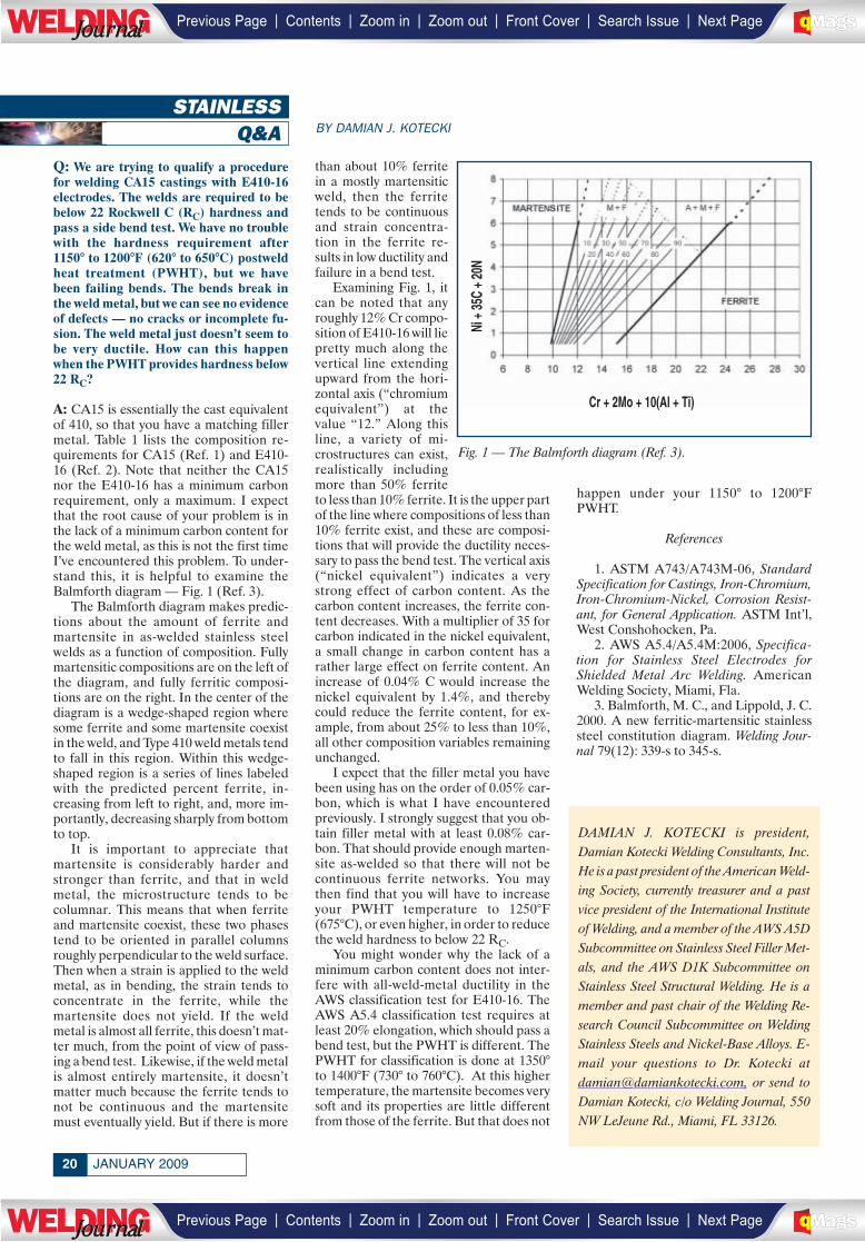
A: CA15 is essentially the cast equivalentof 410, so that you have a matching fillermetal. Table 1 lists the composition re-quirements for CA15 (Ref. 1) and E410-16 (Ref. 2). Note that neither the CA15nor the E410-16 has a minimum carbonrequirement, only a maximum. I expectthat the root cause of your problem is inthe lack of a minimum carbon content forthe weld metal, as this is not the first timeI’ve encountered this problem. To under-stand this, it is helpful to examine theBalmforth diagram — Fig. 1 (Ref. 3).
The Balmforth diagram makes predic-tions about the amount of ferrite andmartensite in as-welded stainless steelwelds as a function of composition. Fullymartensitic compositions are on the left ofthe diagram, and fully ferritic composi-tions are on the right. In the center of thediagram is a wedge-shaped region wheresome ferrite and some martensite coexistin the weld, and Type 410 weld metals tendto fall in this region. Within this wedge-shaped region is a series of lines labeledwith the predicted percent ferrite, in-creasing from left to right, and, more im-portantly, decreasing sharply from bottomto top.
It is important to appreciate thatmartensite is considerably harder andstronger than ferrite, and that in weldmetal, the microstructure tends to becolumnar. This means that when ferriteand martensite coexist, these two phasestend to be oriented in parallel columnsroughly perpendicular to the weld surface.Then when a strain is applied to the weldmetal, as in bending, the strain tends toconcentrate in the ferrite, while themartensite does not yield. If the weldmetal is almost all ferrite, this doesn’t mat-ter much, from the point of view of pass-ing a bend test. Likewise, if the weld metalis almost entirely martensite, it doesn’tmatter much because the ferrite tends tonot be continuous and the martensitemust eventually yield. But if there is more
than about 10% ferritein a mostly martensiticweld, then the ferritetends to be continuousand strain concentra-tion in the ferrite re-sults in low ductility andfailure in a bend test.
Examining Fig. 1, itcan be noted that anyroughly 12% Cr compo-sition of E410-16 will liepretty much along thevertical line extendingupward from the hori-zontal axis (“chromiumequivalent”) at thevalue “12.” Along thisline, a variety of mi-crostructures can exist,realistically includingmore than 50% ferriteto less than 10% ferrite. It is the upper partof the line where compositions of less than10% ferrite exist, and these are composi-tions that will provide the ductility neces-sary to pass the bend test. The vertical axis(“nickel equivalent”) indicates a verystrong effect of carbon content. As thecarbon content increases, the ferrite con-tent decreases. With a multiplier of 35 forcarbon indicated in the nickel equivalent,a small change in carbon content has arather large effect on ferrite content. Anincrease of 0.04% C would increase thenickel equivalent by 1.4%, and therebycould reduce the ferrite content, for ex-ample, from about 25% to less than 10%,all other composition variables remainingunchanged.
I expect that the filler metal you havebeen using has on the order of 0.05% car-bon, which is what I have encounteredpreviously. I strongly suggest that you ob-tain filler metal with at least 0.08% car-bon. That should provide enough marten-site as-welded so that there will not becontinuous ferrite networks. You maythen find that you will have to increaseyour PWHT temperature to 1250°F(675°C), or even higher, in order to reducethe weld hardness to below 22 RC.
You might wonder why the lack of aminimum carbon content does not inter-fere with all-weld-metal ductility in theAWS classification test for E410-16. TheAWS A5.4 classification test requires atleast 20% elongation, which should pass abend test, but the PWHT is different. ThePWHT for classification is done at 1350°to 1400°F (730° to 760°C). At this highertemperature, the martensite becomes verysoft and its properties are little differentfrom those of the ferrite. But that does not
happen under your 1150° to 1200°FPWHT.
References
1. ASTM A743/A743M-06, StandardSpecification for Castings, Iron-Chromium,Iron-Chromium-Nickel, Corrosion Resist-ant, for General Application. ASTM Int’l,West Conshohocken, Pa.
2. AWS A5.4/A5.4M:2006, Specifica-tion for Stainless Steel Electrodes forShielded Metal Arc Welding. AmericanWelding Society, Miami, Fla.
3. Balmforth, M. C., and Lippold, J. C.2000. A new ferritic-martensitic stainlesssteel constitution diagram. Welding Jour-nal 79(12): 339-s to 345-s.
DAMIAN J. KOTECKI is president,Damian Kotecki Welding Consultants, Inc.He is a past president of the American Weld-ing Society, currently treasurer and a pastvice president of the International Instituteof Welding, and a member of the AWS A5DSubcommittee on Stainless Steel Filler Met-als, and the AWS D1K Subcommittee onStainless Steel Structural Welding. He is amember and past chair of the Welding Re-search Council Subcommittee on WeldingStainless Steels and Nickel-Base Alloys. E-mail your questions to Dr. Kotecki [email protected], or send toDamian Kotecki, c/o Welding Journal, 550NW LeJeune Rd., Miami, FL 33126.
Fig. 1 — The Balmforth diagram (Ref. 3).
Ni +
35C
+ 20
N
Cr + 2Mo + 10(Al + Ti)
JANUARY 200920
___________________
| | | | | |Previous Page Contents Zoom in Zoom out Front Cover Search Issue Next PageLWE DINGJournalJournal BA
M SaGEF
| | | | | |Previous Page Contents Zoom in Zoom out Front Cover Search Issue Next PageLWE DINGJournalJournal BA
M SaGEF
For Info go to www.aws.org/ad-index
| | | | | |Previous Page Contents Zoom in Zoom out Front Cover Search Issue Next PageLWE DINGJournalJournal BA
M SaGEF
| | | | | |Previous Page Contents Zoom in Zoom out Front Cover Search Issue Next PageLWE DINGJournalJournal BA
M SaGEF
______________
____________________
RWMAQ&A BY D. F. MAATZ JR.
Q: Which type of transformer is betterfor the resistance spot welding of sheetmetal, alternating current (AC) or mid-frequency direct current (MFDC)? I ammostly concerned with automotive sheetmetal applications but would welcome anythoughts on this subject.
A: The decision to utilize either a MFDCpower supply or AC transformer for re-sistance spot welding is as much a pro-cessing question as it is a welding ques-tion. To help illustrate this, the followingdiscussion of which power supply may bebetter for a particular application can bebroken down into several parts, includingprocessing, facilities, and welding. I alsothink it is important to have some histori-cal perspective on this topic for it actuallyhas a part in answering the question. Fi-nally, this topic has historically generatedmore than a little debate within the resist-ance welding community so do not expecteveryone to agree with this answer.
The MFDC technology was originallydeveloped for automotive resistance spotwelding in the late 1970s as a joint effortby Square D and Goodrich. Square D fo-cused on the weld control while Goodrichconcentrated on the MFDC power sup-ply. At that point in time, General Motorswas a major customer of Square D andwas heavily involved in the developmentprocess of this new technology. The majormotivating factor in the technology devel-opment was a reduction in the weight ofthe transformer. That period in timewithin the automotive body constructionarena witnessed the migration away fromtraditional manually operated handgunstoward robot-mounted weld guns, partic-ularly integrated resistance welding gunscalled transguns. As the robots of the daywere rather limited in their capacity (fig-ure about 60 kg for that time period), theonly way to incorporate a larger weld gundesign was to reduce the weight of otherwelding system components, specificallythe transformer. A secondary motivationwas that MFDC permitted weld guns withlarge secondary loop areas to achievehigher secondary currents, in some casesin excess of 20 kA. This level of second-ary current was difficult to achieve evenwith the utilization of hip-mounted ACtransformers.
When the new MFDC power supplieswere released to the plants there was lit-tle, if any, discussion concerning the ben-efits of lower primary power demand, norwas there any mention of the effectMFDC had on material weldability. Thereare most likely two reasons for this. The
first is that the majority of body shops backthen were electrically overdesigned withregard to primary power. Why? They wereequipped to handle portable gun trans-formers. The primary electrical demandfor portable gun transformers is huge (po-tentially ten times that of MFDC), andsince these electrical systems were alreadyin place, a capital cost reduction was notpossible unless a “greenfield” facility wasbeing launched. As a result, there was verylittle cost savings attached to the actualpower system equipment side. The sec-ond reason had to do with the fact that theMFDC technology was in its infancy andthe facilities engineer was not going to riskdownsizing a plant power system on thisnew technology. The same thinking ap-plied to the welding engineer with respectto weld quality and process robustness.Since the initial goal was mass reductionand increased secondary weld current ca-pability, folks were not looking for, norexpecting, an improvement in materialweldability.
The selection of AC vs. MFDC with re-gard to facilities and tooling is based onits own unique acceptance criteria. Aswith all choices, it is not entirely a blackand white issue and some knowledge ofthe potential compromises and pitfalls isessential to achieve an accurate decision.From a facility perspective, the use ofMFDC represents a major change inthinking as compared to AC. The follow-ing points should help illustrate the dif-ferences, and highlight both possible ad-vantages and disadvantages for each typeof power supply.• MFDC permits equal three-phase cur-
rent distribution and thus a more bal-
anced primary loading condition. AnAC welding system only taps into twoof the three primary bus legs and re-quires a fair amount of facility planningto ensure that each leg on the bus issubjected to relatively the same load.Also, because the single-phase loadsare not synchronized, balancing theload on a three-phase distribution isnearly impossible.
• The selection of MFDC for a large vol-ume installation, such as a newbodyshop, can result in reduced over-all primary demand. This lower pri-mary demand can translate into savingsdue to the lower costs associated withprimary power distribution equipment(smaller circuit breakers, wire, etc.).But since switching from AC to MFDCrequires changing from single-phasebreakers and two-wire systems tothree-phase breakers and three-wiresystems, the true electrical facility costmay be negated. Another importantconsideration is that the typical AC in-stallation requires primary cable ratedat 600 V while an MFDC system gen-erally needs higher rated primary cablebetween the weld control and thepower supply.
• MFDC power supplies possess abroader current range than do their ACcounterparts, so fewer transformermodels are required to cover the fullwelding current spectrum. With MFDCit is possible to equip an entire bodyshop with two sizes of power supplieswhile it might take as many as ten dif-ferent AC transformer models to coverthe same current range.
• Within the world of general automotive
JANUARY 200922
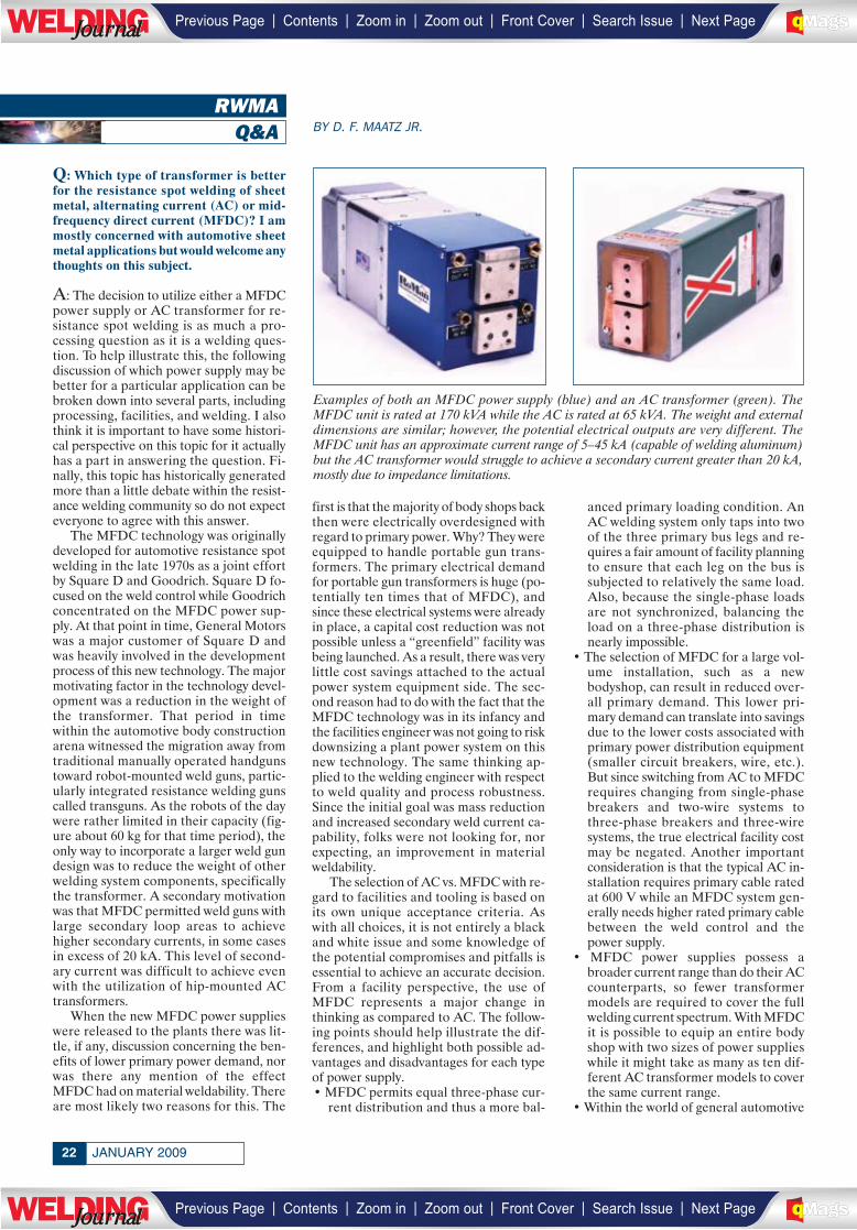
Examples of both an MFDC power supply (blue) and an AC transformer (green). TheMFDC unit is rated at 170 kVA while the AC is rated at 65 kVA. The weight and externaldimensions are similar; however, the potential electrical outputs are very different. TheMFDC unit has an approximate current range of 5–45 kA (capable of welding aluminum)but the AC transformer would struggle to achieve a secondary current greater than 20 kA,mostly due to impedance limitations.
| | | | | |Previous Page Contents Zoom in Zoom out Front Cover Search Issue Next PageLWE DINGJournalJournal BA
M SaGEF
| | | | | |Previous Page Contents Zoom in Zoom out Front Cover Search Issue Next PageLWE DINGJournalJournal BA
M SaGEF
23WELDING JOURNAL
applications (up to ~25 kA) the costof AC transgun transformers vary inprice from $800 to $1500 while theequivalent MFDC units run from$2000 to $3500, depending on features.The same disparity can be seen in theweld controls required for each powersupply with the MFDC suffering an ap-proximate 20% cost penalty. A cau-tionary note on costs: This is one areawhere the application and volume canhave a huge impact. Prices for theMFDC equipment used to be in excessof 2:1 over the comparable AC device,but that gap has narrowed considerablydue to the economies of scale. Thatbeing said, the inherent complexity ofa MFDC resistance welding power sup-ply or weld control will most likely keepit more expensive than its AC equiva-lent for the immediate future.
• MFDC power supply water cooling re-quirements are significantly higherwhen compared to an equivalent ACunit, with the typical flow rate require-ments twice those required of AC. Thesophisticated internal water paths alsodictate a higher differential pressure,and the physical conditioning (i.e., me-chanical filtration, etc.) of the watermust be better to prevent sedimentbuildup due the tortuous water flowpath. Conversely, the AC transformeris much more durable and less proneto failure with respect to water issues.
• The MFDC power supply has a muchshorter life expectancy than its ACcounterpart. This is due to the charac-teristics of a diode when it is thermallycycled and the resultant movement be-tween the wafers in the rectifier packs.In essence the ‘moving parts’ of theMFDC power supply wear out. The typ-ical life span averages 10 –12 millionthermal cycles, but can be higher. Ad-ditionally, the MFDC power supply ismore susceptible to failure due to lowwater flow rates or excessive kVA de-mand. While these same afflictions areharmful to an AC transformer, the mag-nitude of the degradation is much less.
• The higher operating frequency of theMFDC power supply permits for amore controllable situation for theweld control, and results in the deliv-ery of a more accurate weld schedule.MFDC is also less susceptible to theprimary power oscillations in plantsdue to the output being derived fromthree-phase power rather than on a single-phase.The selection of AC vs. MFDC with re-
gard to weld quality is also based on dif-ferences between the two types of powerdelivery systems. However, unlike theitems mentioned in the facilities discus-sion above, the effect of these differenceson welding is not always clear. The subtle
nature of the differences between AC andMFDC and their possible effects on weldquality and process robustness reallyforces each application to be evaluated onits own merits.
There have been multiple peer re-viewed papers published in many forumsregarding the different welding character-istics of AC vs. MFDC, and the results arenot always conclusive or consistent in de-termining which process is capable of pro-ducing better weld quality. These studies,which included advanced high-strengthsteels (AHSS), looked at many aspects ofthe two welding processes and ranged inscope from the physical properties of theweld to the effect of weld current conduc-tion angle and its direct effect on the in-herent inter-cycle cooling associated withAC power vs. the lack of inter-cycle cool-ing with MFDC. One auto company per-formed an in-house study to determinewhether the polarity effects of MFDC cur-rent were significant. The responses stud-ied included weld range comparisons,electrode life evaluations, and static anddynamic mechanical studies of weldstrength. Despite all this hard work andanalysis, an all-inclusive answer still hasnot been found. Put another way, while aparticular application or specific materialmay benefit from utilizing either AC orMFDC, the results to date do not permitanyone to make broad statements with re-gard to material weldability such as “allgalvanized materials weld better with AC”or that “all stack-up ratios in excess of 4:1weld better with MFDC.”
At the end of the day, there are notmany automotive resistance spot weldsthat cannot be made with either AC orMFDC, and the selection of either of thetwo is going to be driven much more byfacility and tooling considerations thanwelding. Bottom line, asking if AC orMFDC is better is like asking if a car isbetter than a truck. Without clarifying thecriteria for a particular application the an-swer is really hard to determine.◆
DONALD F. MAATZ JR. is laboratory man-ager, RoMan Engineering Services. He is amember of the AWS Detroit SectionExecutive Committee, serves on the D8 and D8D Automotive WeldingCommittees, is vice chairman of theRWMA Technical Committee, and is agraduate of The Ohio State University witha BS in welding engineering. This articlewould not have been possible were it notfor the assistance of Don DeCorte andother members of the RoMan team. Sendyour comments/questions [email protected], or to DonMaatz, c/o Welding Journal, 550 NWLeJeune Rd., Miami, FL 33126.
For info go to www.aws.org/ad-index
________________
| | | | | |Previous Page Contents Zoom in Zoom out Front Cover Search Issue Next PageLWE DINGJournalJournal BA
M SaGEF
| | | | | |Previous Page Contents Zoom in Zoom out Front Cover Search Issue Next PageLWE DINGJournalJournal BA
M SaGEF
__________________
______________
LETTERS TO THEEDITOR
San Jacinto College’s WeldingProgram Praised
This letter is in reference to Howard Wood-ward’s article, ‘Inspired Welding Instructorsand Great Facilities Make the Difference atSan Jacinto College,’ published in the No-vember 2008 Welding Journal, pages83–85.
I was pleased to see the article in theNovember issue of Welding Journal aboutthe welding program at San Jacinto Col-lege. Since graduating from there in 2003,I’ve often felt that the San Jacinto pro-gram deserved publicity beyond the south-east corner of Harris County, Tex., wherethe school is located. I’ve also felt thatTiburcio Parras, who was mentioned inthe article, deserves particular recogni-tion. Among the several good welding in-structors I had at San Jacinto, none wasbetter than “Tivo” Parras.
I was not a typical San Jacinto student.Unlike most of my classmates who werelooking for skills to start a career, I wasalready pretty well set. I was a professionalengineer with two degrees in mechanicalengineering from Rice University. Afterearning those degrees in the 1970s, I hadgone to work for an oilfield equipmentmanufacturer. Ten years later, I moved toNASA’s scientific balloon facility in Pales-tine, Tex., where I had the good fortuneto work with two skilled welders. In work-ing with those guys for several years, Icame to realize that the hands-on workthey did on the weldments I designed gavethem an investment in those structuresthat I couldn’t fully share. When I re-turned to Houston for a job at JohnsonSpace Center, I enrolled in the eveningprogram at San Jacinto College, deter-mined to learn what a welder knows.While I’m sure I was not the first engineerfrom the nearby petrochemical and spaceindustries to enroll in the San Jacinto pro-gram, as far as I know I was the only oneenrolled in the program during the fouryears I was there.
I met Tivo Parras halfway through mytime at San Jacinto. When I first showedup in his GTAW class, I think Tivo was alittle dubious, because, frankly, I was slowto learn the two-handed skill. Still, Tivoreadily accepted me as another student onthe roll, since he was a one-man recruit-ing machine for the welding program witha gift for bringing in and keeping students.By my second semester with him, Tivo hadme pegged. He said he worried about mesometimes when he didn’t see any arc lightcoming from my booth, because he knew
I was in there thinking about welding, in-stead of just welding. Nevertheless, Tivolet me continue to think and weld, becausehe understood that I learned by thinking,as well as by doing. He eventually gave mea simple but significant compliment whenhe told me, in my third semester with him,that he thought I could actually get a jobas a welder.
Tivo and the other instructors at SanJacinto were excellent at teaching me“how” to weld. They offered less instruc-tion on “why” welding processes work theway they do, so I pursued those questionson my own. I joined AWS while at San Jac-into, and I bought several books fromAWS and Lincoln Electric and studiedthem to supplement what I was learningin class. About a year after I finished theSan Jacinto program, I took Ohio’s prin-ciples and practice exam in welding engi-neering as an objective way to gauge whatI knew about the science of welding. Pass-ing that test earned me the CertifiedWelding Engineer credential from AWS.I then prepared for and passed the Certi-fied Welding Inspector exam with the helpof a one-semester prep course at San Jac-into. That effort gave me yet another per-spective on welding and provided me witha more common and better understoodAWS credential of welding knowledge.
Training at San Jacinto opened a win-dow onto welding for me at a time in mycareer when I was best positioned to enjoythe benefits. Though I had seen weldingbriefly in an industrial process lab coursewhen I was an undergrad at Rice, I didn’tget much out of that early exposure. It wasjust one of many subjects to be learnedthen, presented without much context tosuggest how valuable an understanding ofwelding might be someday. In that, I thinkmy experience was typical, and it may ex-plain a lot about the “house divided” thatI see in the welding industry today.
In learning to weld and, even more so,in training to become a CWI, I was disap-pointed by the level of suspicion and con-tempt toward engineers I found in somecircles in the world of welding. I won’t sayanything more here to add fuel to that fire,which is always ready to flare up, but whichusually generates more heat than light. In-stead, I will suggest that I think there is aneed (and an opportunity) for AWS to doa better job of disseminating practicalwelding knowledge to engineers. I thinkthere might be two avenues for this. Onewould be a more direct outreach effort byAWS to mechanical and civil engineeringundergraduate students. Another avenuemight be a cooperative effort betweenAWS and community colleges to establish
some type of short, “finishing school” cur-riculum aimed at degreed engineers whohave been out of school and in the work-place long enough to recognize that theremight be a hole in their education wherewelding is concerned.
Certainly, there are many well-trainedwelding engineers around the world doingexcellent work every day to advance theart and science of welding. Likewise, oth-ers are serving industry by their tirelesswork on refining and applying the exten-sive and universally respected weldingcodes. Unfortunately, my experience tellsme it’s also true that in most small tomedium sized companies the person mostknowledgeable about welding — the defacto welding engineer in the enterprise— is that individual who knows how toturn on the welding machine and strike anarc. In that situation, welds on the com-pany’s products and equipment may be ofadequate or even superior quality. Or theymay not be. Who is to say for sure if weld-ing requirements are not effectively de-scribed in the company’s product andequipment documentation and if there isnot some welding knowledge link betweenthe shop floor and the front office?
Ed Fritsch,AWS Houston Section
P.E., CWEng., CWI
Dear Readers:
The Welding Journal encour-ages an exchange of ideas through letters to the editor. Please sendyour letters to the Welding Jour-nal Dept., 550 NW LeJeune Rd.,Miami, FL 33126. You can alsoreach us by FAX at (305) 443-7404or by sending an e-mail to KristinCampbell at [email protected].
JANUARY 200924
Change of Address?Moving?
Make sure delivery of your WeldingJournal is not interrupted. Contact theMembership Department with yournew address information — (800) 443-9353, ext. 217; [email protected].
______________
___________
| | | | | |Previous Page Contents Zoom in Zoom out Front Cover Search Issue Next PageLWE DINGJournalJournal BA
M SaGEF
| | | | | |Previous Page Contents Zoom in Zoom out Front Cover Search Issue Next PageLWE DINGJournalJournal BA
M SaGEF
For Info go to www.aws.org/ad-index
_______________________
| | | | | |Previous Page Contents Zoom in Zoom out Front Cover Search Issue Next PageLWE DINGJournalJournal BA
M SaGEF
| | | | | |Previous Page Contents Zoom in Zoom out Front Cover Search Issue Next PageLWE DINGJournalJournal BA
M SaGEF
____________________
______________
NEWPRODUCTS
GMAW AccessoriesImprove User Comfort
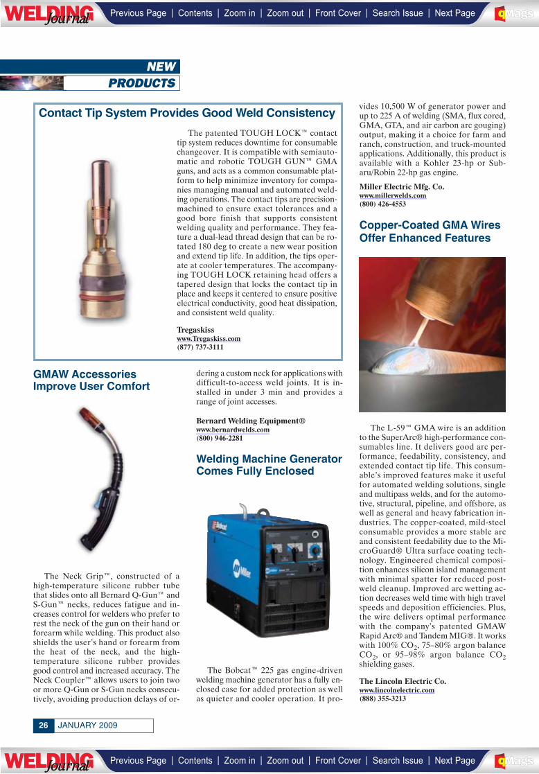
The Neck Grip™, constructed of ahigh-temperature silicone rubber tubethat slides onto all Bernard Q-Gun™ andS-Gun™ necks, reduces fatigue and in-creases control for welders who prefer torest the neck of the gun on their hand orforearm while welding. This product alsoshields the user’s hand or forearm fromthe heat of the neck, and the high-temperature silicone rubber providesgood control and increased accuracy. TheNeck Coupler™ allows users to join twoor more Q-Gun or S-Gun necks consecu-tively, avoiding production delays of or-
dering a custom neck for applications withdifficult-to-access weld joints. It is in-stalled in under 3 min and provides arange of joint accesses.
Bernard Welding Equipment®www.bernardwelds.com(800) 946-2281
Welding Machine GeneratorComes Fully Enclosed
The Bobcat™ 225 gas engine-drivenwelding machine generator has a fully en-closed case for added protection as wellas quieter and cooler operation. It pro-
vides 10,500 W of generator power andup to 225 A of welding (SMA, flux cored,GMA, GTA, and air carbon arc gouging)output, making it a choice for farm andranch, construction, and truck-mountedapplications. Additionally, this product isavailable with a Kohler 23-hp or Sub-aru/Robin 22-hp gas engine.
Miller Electric Mfg. Co.www.millerwelds.com(800) 426-4553
Copper-Coated GMA WiresOffer Enhanced Features
The L-59™ GMA wire is an additionto the SuperArc® high-performance con-sumables line. It delivers good arc per-formance, feedability, consistency, andextended contact tip life. This consum-able’s improved features make it usefulfor automated welding solutions, singleand multipass welds, and for the automo-tive, structural, pipeline, and offshore, aswell as general and heavy fabrication in-dustries. The copper-coated, mild-steelconsumable provides a more stable arcand consistent feedability due to the Mi-croGuard® Ultra surface coating tech-nology. Engineered chemical composi-tion enhances silicon island managementwith minimal spatter for reduced post-weld cleanup. Improved arc wetting ac-tion decreases weld time with high travelspeeds and deposition efficiencies. Plus,the wire delivers optimal performancewith the company’s patented GMAWRapid Arc® and Tandem MIG®. It workswith 100% CO2, 75–80% argon balanceCO2, or 95–98% argon balance CO2shielding gases.
The Lincoln Electric Co.www.lincolnelectric.com(888) 355-3213
JANUARY 200926
Contact Tip System Provides Good Weld Consistency
The patented TOUGH LOCK™ contacttip system reduces downtime for consumablechangeover. It is compatible with semiauto-matic and robotic TOUGH GUN™ GMAguns, and acts as a common consumable plat-form to help minimize inventory for compa-nies managing manual and automated weld-ing operations. The contact tips are precision-machined to ensure exact tolerances and agood bore finish that supports consistentwelding quality and performance. They fea-ture a dual-lead thread design that can be ro-tated 180 deg to create a new wear positionand extend tip life. In addition, the tips oper-ate at cooler temperatures. The accompany-ing TOUGH LOCK retaining head offers atapered design that locks the contact tip inplace and keeps it centered to ensure positiveelectrical conductivity, good heat dissipation,and consistent weld quality.
Tregaskisswww.Tregaskiss.com(877) 737-3111
| | | | | |Previous Page Contents Zoom in Zoom out Front Cover Search Issue Next PageLWE DINGJournalJournal BA
M SaGEF
| | | | | |Previous Page Contents Zoom in Zoom out Front Cover Search Issue Next PageLWE DINGJournalJournal BA
M SaGEF
____________
____________
_____________
______________

2727WELDING JOURNAL
Welding Helmets IncludeOff-Road Graphic Design
The Prowler Series of autodarkeningwelding helmets features a 23⁄8- × 37⁄8-in.viewing area with four independent sen-sors that provide continuous arc-sensingcapability for out-of-position welding. ItsOff-Road design is set on top of a glossyblack finish; mud and dirt are also pic-tured clinging to a massive tire and shocktower of a typical rock crawling rig. The
lens darkens in 1/20,000 of a second afterarc start and features an internally ad-justable autodarkening shade (#9–13),lens sensitivity, and delay controls. Thesehelmets feature solar-assisted autodark-ening lenses and easy-to-replace lithiumbatteries lasting up to 3000 h when GMAwelding. The Off-Road helmet comes withfive external and two internal protectivelens covers as well. The Series improvescomfort and eliminates pinched hair witha redesigned ratchet-style headgear andCoolMax® odor-absorbing sweatband.
Hobart Welding Productswww.hobartwelders.com(877) 462-2781
Large Collector ContainsMovable Arm
The Rollatron portable air cleaner is a1500 ft3/min, three cartridge, self-clean-ing unit for grinding, hardfacing, andwelding (such as heavy FCA or SMA) ap-plications. It has a slow “can velocity” al-lowing for the dirt to settle to the bottomof the dust tray and remain there. It comesstandard with the Texas Twister spark trap,providing quick and easy cleaning with-out opening the unit. Additional features
include the following: 10 ft × 8-in.-diame-ter arm; 10-in.-diameter front wheels, 4-× 2-in. rear lockable; high-efficiency fil-ters; washable prefiltration section; BIblowers with TEFC motors; toolless filterdoor; and easy filter changeout.
Filter-1, Inc.www.filter-1.com(800) 289-0189
For info go to www.aws.org/ad-index
| | | | | |Previous Page Contents Zoom in Zoom out Front Cover Search Issue Next PageLWE DINGJournalJournal BA
M SaGEF
| | | | | |Previous Page Contents Zoom in Zoom out Front Cover Search Issue Next PageLWE DINGJournalJournal BA
M SaGEF
______________
__________
__________________________
______________
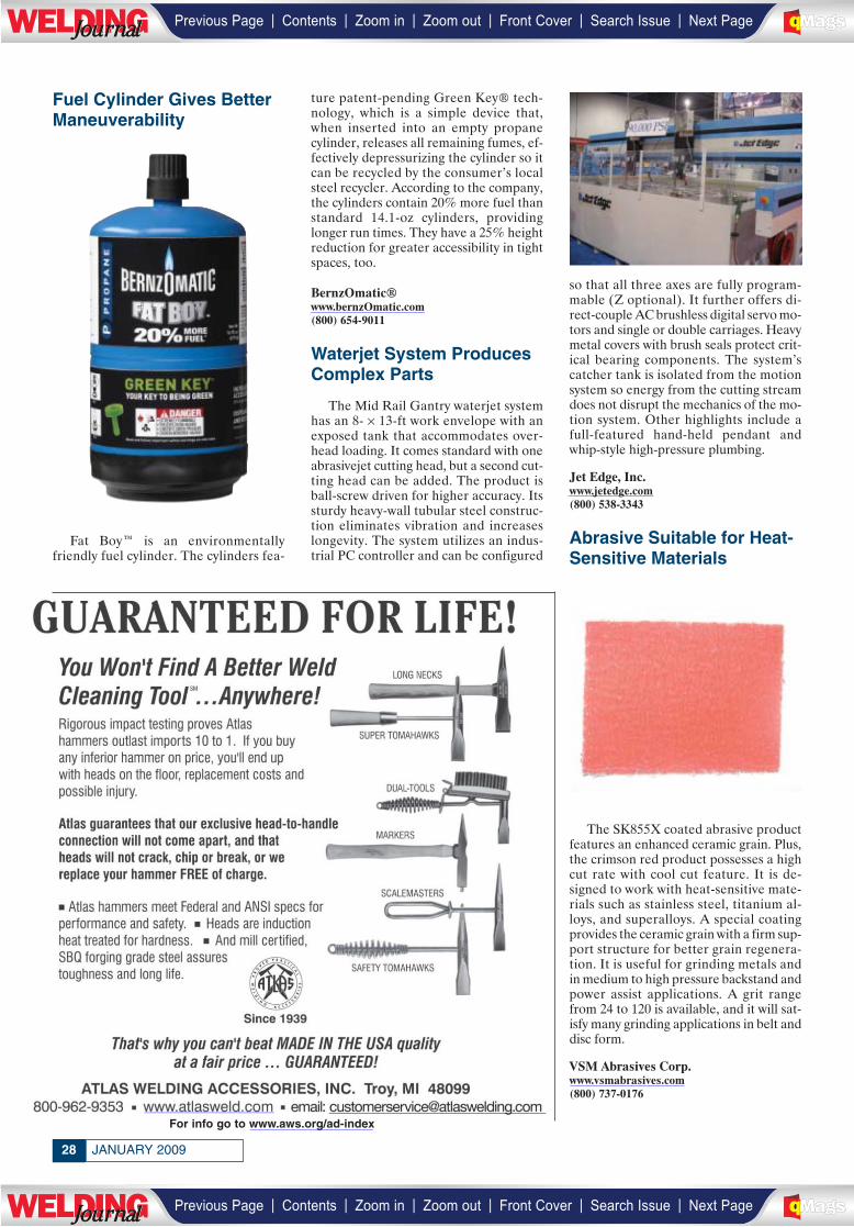
Fuel Cylinder Gives BetterManeuverability
Fat Boy™ is an environmentallyfriendly fuel cylinder. The cylinders fea-
ture patent-pending Green Key® tech-nology, which is a simple device that,when inserted into an empty propanecylinder, releases all remaining fumes, ef-fectively depressurizing the cylinder so itcan be recycled by the consumer’s localsteel recycler. According to the company,the cylinders contain 20% more fuel thanstandard 14.1-oz cylinders, providinglonger run times. They have a 25% heightreduction for greater accessibility in tightspaces, too.
BernzOmatic®www.bernzOmatic.com(800) 654-9011
Waterjet System ProducesComplex Parts
The Mid Rail Gantry waterjet systemhas an 8- × 13-ft work envelope with anexposed tank that accommodates over-head loading. It comes standard with oneabrasivejet cutting head, but a second cut-ting head can be added. The product isball-screw driven for higher accuracy. Itssturdy heavy-wall tubular steel construc-tion eliminates vibration and increaseslongevity. The system utilizes an indus-trial PC controller and can be configured
so that all three axes are fully program-mable (Z optional). It further offers di-rect-couple AC brushless digital servo mo-tors and single or double carriages. Heavymetal covers with brush seals protect crit-ical bearing components. The system’scatcher tank is isolated from the motionsystem so energy from the cutting streamdoes not disrupt the mechanics of the mo-tion system. Other highlights include afull-featured hand-held pendant andwhip-style high-pressure plumbing.
Jet Edge, Inc.www.jetedge.com(800) 538-3343
Abrasive Suitable for Heat-Sensitive Materials
The SK855X coated abrasive productfeatures an enhanced ceramic grain. Plus,the crimson red product possesses a highcut rate with cool cut feature. It is de-signed to work with heat-sensitive mate-rials such as stainless steel, titanium al-loys, and superalloys. A special coatingprovides the ceramic grain with a firm sup-port structure for better grain regenera-tion. It is useful for grinding metals andin medium to high pressure backstand andpower assist applications. A grit rangefrom 24 to 120 is available, and it will sat-isfy many grinding applications in belt anddisc form.
VSM Abrasives Corp.www.vsmabrasives.com(800) 737-0176
JANUARY 200928
For info go to www.aws.org/ad-index________________________
| | | | | |Previous Page Contents Zoom in Zoom out Front Cover Search Issue Next PageLWE DINGJournalJournal BA
M SaGEF
| | | | | |Previous Page Contents Zoom in Zoom out Front Cover Search Issue Next PageLWE DINGJournalJournal BA
M SaGEF
_____________
__________
_____________
______________
_______________
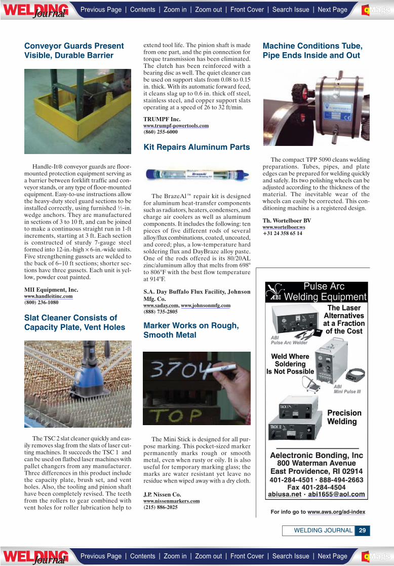
Conveyor Guards PresentVisible, Durable Barrier
Handle-It® conveyor guards are floor-mounted protection equipment serving asa barrier between forklift traffic and con-veyor stands, or any type of floor-mountedequipment. Easy-to-use instructions allowthe heavy-duty steel guard sections to beinstalled correctly, using furnished ½-in.wedge anchors. They are manufacturedin sections of 3 to 10 ft, and can be joinedto make a continuous straight run in 1-ftincrements, starting at 3 ft. Each sectionis constructed of sturdy 7-gauge steelformed into 12-in.-high × 6-in.-wide units.Five strengthening gussets are welded tothe back of 6–10 ft sections; shorter sec-tions have three gussets. Each unit is yel-low, powder coat painted.
MII Equipment, Inc.www.handleitinc.com(800) 236-1080
Slat Cleaner Consists ofCapacity Plate, Vent Holes
The TSC 2 slat cleaner quickly and eas-ily removes slag from the slats of laser cut-ting machines. It succeeds the TSC 1 andcan be used on flatbed laser machines withpallet changers from any manufacturer.Three differences in this product includethe capacity plate, brush set, and ventholes. Also, the tooling and pinion shafthave been completely revised. The teethfrom the rollers to gear combined withvent holes for roller lubrication help to
extend tool life. The pinion shaft is madefrom one part, and the pin connection fortorque transmission has been eliminated.The clutch has been reinforced with abearing disc as well. The quiet cleaner canbe used on support slats from 0.08 to 0.15in. thick. With its automatic forward feed,it cleans slag up to 0.6 in. thick off steel,stainless steel, and copper support slatsoperating at a speed of 26 to 32 ft/min.
TRUMPF Inc.www.trumpf-powertools.com(860) 255-6000
Kit Repairs Aluminum Parts
The BrazeAl™ repair kit is designedfor aluminum heat-transfer componentssuch as radiators, heaters, condensers, andcharge air coolers as well as aluminumcomponents. It includes the following: tenpieces of five different rods of severalalloy/flux combinations, coated, uncoated,and cored; plus, a low-temperature hardsoldering flux and DayBraze alloy paste.One of the rods offered is its 80/20ALzinc/aluminum alloy that melts from 698°to 806°F with the best flow temperatureat 914°F.
S.A. Day Buffalo Flux Facility, JohnsonMfg. Co.www.saday.com, www.johnsonmfg.com(888) 735-2805
Marker Works on Rough,Smooth Metal
The Mini Stick is designed for all pur-pose marking. This pocket-sized markerpermanently marks rough or smoothmetal, even when rusty or oily. It is alsouseful for temporary marking glass; themarks are water resistant yet leave noresidue when wiped away with a dry cloth.
J.P. Nissen Co.www.nissenmarkers.com(215) 886-2025
Machine Conditions Tube,Pipe Ends Inside and Out
The compact TPP 5090 cleans weldingpreparations. Tubes, pipes, and plateedges can be prepared for welding quicklyand safely. Its two polishing wheels can beadjusted according to the thickness of thematerial. The inevitable wear of thewheels can easily be corrected. This con-ditioning machine is a registered design.
Th. Wortelboer BVwww.wortelboer.ws+31 24 358 65 14
29WELDING JOURNAL
For info go to www.aws.org/ad-index
______________
| | | | | |Previous Page Contents Zoom in Zoom out Front Cover Search Issue Next PageLWE DINGJournalJournal BA
M SaGEF
| | | | | |Previous Page Contents Zoom in Zoom out Front Cover Search Issue Next PageLWE DINGJournalJournal BA
M SaGEF
________________
___________
____________
_________ ____________
______________________
______________
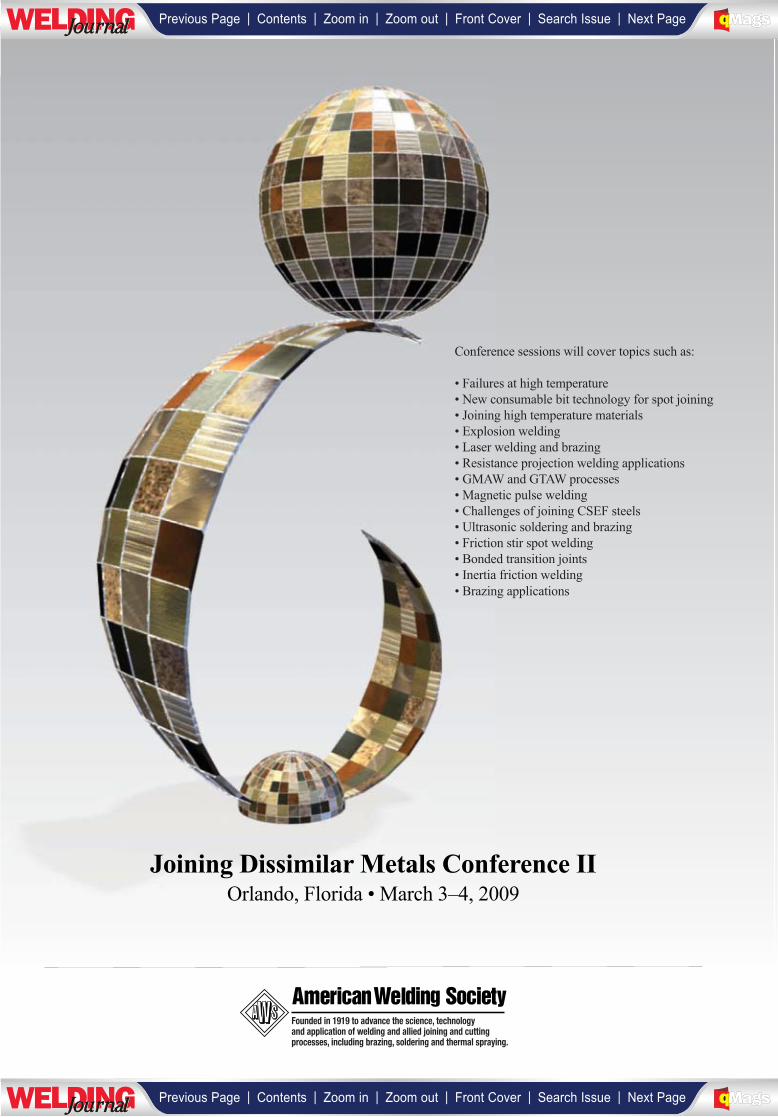
Founded in 1919 to advance the science, technologyand application of welding and allied joining and cuttingprocesses, including brazing, soldering and thermal spraying.
Joining Dissimilar Metals Conference IIOrlando, Florida • March 3–4, 2009
Conference sessions will cover topics such as:
• Failures at high temperature
• New consumable bit technology for spot joining
• Joining high temperature materials
• Explosion welding
• Laser welding and brazing
• Resistance projection welding applications
• GMAW and GTAW processes
• Magnetic pulse welding
• Challenges of joining CSEF steels
• Ultrasonic soldering and brazing
• Friction stir spot welding
• Bonded transition joints
• Inertia friction welding
• Brazing applications
| | | | | |Previous Page Contents Zoom in Zoom out Front Cover Search Issue Next PageLWE DINGJournalJournal BA
M SaGEF
| | | | | |Previous Page Contents Zoom in Zoom out Front Cover Search Issue Next PageLWE DINGJournalJournal BA
M SaGEF
To register or to receive a descriptive brochure, call (800) 443-9353 ext. 455, (outside North America, call 305-443-9353),
or visit www.aws.org/conferences
Oneof the most discussed topics and sources of misunderstanding involves joining dissimilar materials by welding. Vendors
probably receive more phone calls with questions on this subject than any other. The traditional welding codes are nearly silent on
the issue. Many companies do not have—or have lost—expertise in this area.
The most difficult-to-weld challenges—including various material combinations involving aluminum, creep-enhanced ferritic steels,
nickel alloys, titanium, copper, ceramics, and more—will be covered. New chemistries are coming to the aid of existing filler metals,
making them more amenable to dissimilar metals welding. Advances in ultrasonic and laser brazing, projection and consumable bit
resistance welding, friction stir welding, hot-wire GTAW, controlled short-circuit transfer GMAW, explosion welding, and magnetic pulse
welding will also be discussed in terms of their successful application to the joining of dissimilar materials.
Joining DissimilarMetals Conference IIHilton in theWalt DisneyWorld ResortOrlando, Florida •March 3-4, 2009
Understanding and Avoiding DissimilarWeld Failures at High TemperatureJohn N. DuPont, R.D. Stout Distinguished Professor of Materials
Science and Engineering and Associate Director of the Energy
Research Center, Lehigh University
Dissimilar Joining of High TemperatureMaterials Using a New Nickel-Base FillerMetalGreg Chirieleison, Technical Services Manager, Haynes Wire
Co.
Explosion Welding – AHighly VersatileWelding TechnologyJeffrey A. Nicol, Vice President, Sales and Marketing, DMC Clad
Metal
LaserWelding and Laser BrazingApplicationsCraig Bratt, Fraunhofer Center for Coatings and Laser
Applications
Dissimilar Materials Projection Welding–Bonding Mechanisms and ProcessCharacteristicsJerry E. Gould, Technology Leader, Resistance Welding and
Solid State Welding Processes, Edison Welding Institute
Spot Joining of Dissimilar Combinations ofSteel and Light Metals Using a NewConsumable Bit TechnologyMichael Miles, Associate Professor, Manufacturing Engineering
Technology, Brigham Young University; and Zhili Feng, Group
Leader, Materials Joining and NDE Group, Materials Science and
Technology Division, Oak Ridge National Laboratory
Brazing of Dissimilar Metals – Challengesand OpportunitiesAmit Jain, Senior Brazing Applications Engineer, Lucas-
Milhaupt, Inc. - A Handy & Harman Company.
AGMA and GTAProcess for the Welding ofDissimilar MetalsTom Rankin, Vice President and GM, ITW Jetline Engineering
The Role of Ferrite in Dissimilar MetalWeldingDonald J. Tillack, Consultant to the Nickel Institute
Dissimilar Joining Challenges with CreepStrength-Enhanced Ferritic SteelsWilliam F. Newell, Vice President, Euroweld Ltd.
Ultrasonic Soldering and Brazing ofDissimilar MaterialsShankar P. Srinivasan, Tim Frech, Dan Hauser, and Karl
Graff, Edison Welding Institute
Friction Stir Spot Welding of DissimilarAlloysTom North, Department of Materials Science and Engineering,
University of Toronto
Metallurgically Bonded Transition JointsBrett H. Keener, General Manager, Sypris Technologies, Tube
Turns Division
Bimetal Welds: Is a High Level of IntegrityPossible in Tubulars?Al Wadleigh, President, Interface Welding
Magnetic Pulse Welding Joins DissimilarMetalsJeff Compton, Advanced Computational & Engineering
Services
| | | | | |Previous Page Contents Zoom in Zoom out Front Cover Search Issue Next PageLWE DINGJournalJournal BA
M SaGEF
| | | | | |Previous Page Contents Zoom in Zoom out Front Cover Search Issue Next PageLWE DINGJournalJournal BA
M SaGEF
__________________

JANUARY 200932
The major impetus for develop-ments in high-strength steels(HSS) has been provided by theneed for higher strength, in-
creased toughness, and improved weld-ability (Ref. 1). High-strength steels withyield strengths of 450 MPa (X70) and 550MPa (X80) are increasingly specified for
use in different structural applications re-sulting in weight and cost savings throughthe use of thinner sections (Refs. 2, 3).Additional refinement of chemical com-position and processing procedures haveresulted in the development and testingof higher-strength steels, X100 and X120(Refs. 4, 5). As a result, new developments
in welding processes and consumables toproduce weld metal deposits with me-chanical properties essentially equivalentto the base metal are continually needed.To achieve this, however, proper under-standing of chemistry- and microstruc-ture-property relationships in HSS weldmetals is required.
Characterization of High-Strength Steel Weld Metal
High-strength steel weld metals weredeposited using different weldingprocesses and commercially available con-sumables. Welds were produced using flux-shielded processes such as flux cored arcwelding (FCAW) and shielded metal arcwelding (SMAW) and gas-shieldedprocesses such as gas metal arc welding(GMAW). Flux cored arc welding includedboth self- (T-8 type) and gas-shielded elec-trodes. Cellulosic and basic electrodeswere used with the SMAW process. Thenominal strength of the welding consum-ables ranged from 490 to 840 MPa (70 to120 ksi). Table 1 provides a summary ofthe consumables, welding processes, andweld identifications (W1 to W14) used inthis study. Welding parameters are sum-marized in Table 2. Figure 1 shows a gen-eral view of a welded joint prepared forweld metal characterization.
The mechanical characterization of theHSS weld metals deposited included ten-sile properties, Charpy impact properties,
Examining theExamining theMechanical PropertiesMechanical Propertiesof High-Strength of High-Strength Steel Weld MetalsSteel Weld MetalsTensile, Charpy impact toughness, and crack-tip opening displacement toughnessof high-strength steel weld metals were characterized
BY JOSE E. RAMIREZ
JOSE E. RAMIREZ ([email protected]) is principal engineer, Edison Welding Institute, Columbus, Ohio.
Fig. 1 — General view of the welded joint.
____________
| | | | | |Previous Page Contents Zoom in Zoom out Front Cover Search Issue Next PageLWE DINGJournalJournal BA
M SaGEF
| | | | | |Previous Page Contents Zoom in Zoom out Front Cover Search Issue Next PageLWE DINGJournalJournal BA
M SaGEF
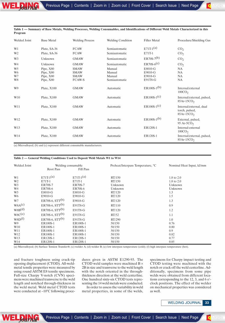
33WELDING JOURNAL
and fracture toughness using crack-tipopening displacement (CTOD). All-weld-metal tensile properties were measured byusing round ASTM E8 tensile specimens.Full-size Charpy V-notch (CVN) speci-mens were machined transverse to the weldlength and notched through-thickness inthe weld metal. Weld metal CTOD testswere conducted at –10°C following proce-
dures given in ASTM E1290-93. TheCTOD weld samples were machined B ×2B in size and transverse to the weld lengthwith the notch oriented in the through-thickness direction at the weld centerline.One hundred sixty-six CTOD tests repre-senting the 14 weld metals were conducted.
In order to assess the variability in weldmetal properties, in some of the welds,
specimens for Charpy impact testing andCTOD testing were machined with thenotch or crack off the weld centerline. Ad-ditionally, specimens from some pipewelds were obtained from different loca-tions corresponding to the 12, 3, and 6 o’-clock positions. The effect of the welderon mechanical properties was consideredas well.
Table 1 — Summary of Base Metals, Welding Processes, Welding Consumables, and Identifications of Different Weld Metals Characterized in thisProgram
Welded Joint Base Metal Welding Process Welding Condition Filler Metal Procedure/Shielding Gas
W1 Plate, SA-36 FCAW Semiautomatic E71T-1(a) CO2W2 Plate, SA-36 FCAW Semiautomatic E71T-1 CO2
W3 Unknown GMAW Semiautomatic ER70S-7(b) CO2
W4 Unknown GMAW Semiautomatic ER70S-6(c) CO2W5 Pipe, X80 SMAW Manual E8010-G NAW6 Pipe, X80 SMAW Manual E9010-G NAW7 Pipe, X80 SMAW Manual E9018-G NAW8 Pipe, X80 FCAW-S Semiautomatic E91T8-G NA
W9 Plate, X100 GMAW Automatic ER100S-1(b) Internal/external100CO2
W10 Plate, X100 GMAW Automatic ER100S-1(c) Internal/external, pulsed,85Ar-15CO2
W11 Plate, X100 GMAW Automatic ER100S-1(c) Internal/external, dual torch, pulsed, 85Ar-15CO2
W12 Plate, X100 GMAW Automatic ER100S-1(b) External, pulsed, 95 Ar-5CO2
W13 Plate, X100 GMAW Automatic ER120S-1 Internal-external 100CO2
W14 Plate, X100 GMAW Automatic ER120S-1 Internal/external, pulsed,85Ar-15CO2
(a) Microalloyed; (b) and (c) represent different consumable manufacturers.
Table 2 — General Welding Conditions Used to Deposit Weld Metals W1 to W14
Welded Joint Welding consumable Preheat/Interpass Temperature, °C Nominal Heat Input, kJ/mmRoot Pass Fill Pass
W1 E71T-1(a) E71T-1(a) RT/150 1.8 to 2.0W2 E71T-1 E71T-1 RT/150 1.8 to 2.0W3 ER70S-7 ER70S-7 Unknown UnknownW4 ER70S-6 ER70S-6 Unknown UnknownW5 E8010-G E8010-G RT/120 1.3W6 E9010-G E9010-G RT/120 1.5
W7 ER70S-6, STT(b) E9018-G RT/120 1.3
W8A(c) ER70S-6, STT(b) E91T8-G RT/110 0.9
W8B(d) ER70S-6, STT(b) E91T8-G RT/120 1.2
W8C(e) ER70S-6, STT(b) E91T8-G RT/52 1.1
W8D(f) ER70S-6, STT(b) E91T8-G RT/290 1.0W9 ER100S-1 ER100S-1 50/150 0.76W10 ER100S-1 ER100S-1 50/150 0.80W11 ER100S-1 ER100S-1 50/150 0.9W12 ER100S-1 ER100S-1 50/150 0.82W13 ER120S-1 ER120S-1 50/150 0.77W14 ER120S-1 ER120S-1 50/150 0.85
(a) Microalloyed; (b) Surface Tension Transfer®; (c) welder A; (d) welder B; (e) low interpass temperature (cold); (f) high interpass temperature (hot).
| | | | | |Previous Page Contents Zoom in Zoom out Front Cover Search Issue Next PageLWE DINGJournalJournal BA
M SaGEF
| | | | | |Previous Page Contents Zoom in Zoom out Front Cover Search Issue Next PageLWE DINGJournalJournal BA
M SaGEF
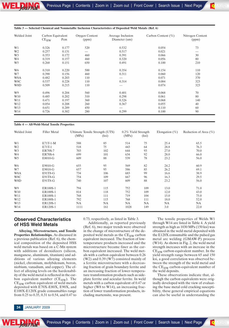
JANUARY 200934
Observed Characteristicsof HSS Weld Metals
Alloying, Microstructure, and TensileProperties Relationships. As discussed ina previous publication (Ref. 6), the chem-ical composition of the deposited HSSweld metals was based on a C-Mn systemwith additions of deoxidizers (silicon,manganese, aluminum, titanium) and ad-ditions of various alloying elements(nickel, chromium, molybdenum, boron,niobium, vanadium, and copper). The ef-fect of alloying levels on the hardenabil-ity of the weld metal is reflected in the car-bon equivalent number (CEIIW). TheCEIIW carbon equivalent of weld metalsdeposited with E70X-E80X, E90X, andE100X-E120X grade consumables rangefrom 0.25 to 0.35, 0.31 to 0.54, and 0.47 to
0.73, respectively, as listed in Table 3. Additionally, as reported previously
(Ref. 6), two major trends were observedin the change of microstructure of the de-posited weld metals as the CEIIW carbonequivalent increased. The fraction of low-temperature products increased and themicrostructure became finer as the car-bon equivalent increased. The weld met-als with a carbon equivalent between 0.26(W2) and 0.39 (W7) consisted mainly ofa ferritic microstructure with a decreas-ing fraction of grain boundary ferrite andan increasing fraction of lower-tempera-ture transformation products such as side-plate ferrite and acicular ferrite. In weldmetals with a carbon equivalent of 0.47 orhigher (W8 to W14), an increasing frac-tion of lower transformation products, in-cluding martensite, was present.
The tensile properties of Welds W1through W14 are listed in Table 4. A yieldstrength as high as 1030 MPa (150 ksi) wasobtained in the weld metal deposited withthe E120X consumable and the pulsed gasmetal arc welding (GMAW-P) process(W14). As shown in Fig. 2, the weld metalstrength increases with an increase in theCEIIW carbon-equivalent number. In theyield strength range between 65 and 150ksi, a good correlation was observed be-tween the strength of the weld metal andthe CEIIW carbon-equivalent number ofthe weld deposits.
These observations indicate that, al-though the carbon equivalents were orig-inally developed with the view of evaluat-ing the base metal cold cracking suscepti-bility, these general empirical equationscan also be useful in understanding the
Table 3 — Selected Chemical and Nonmetallic Inclusion Characteristics of Deposited Weld Metals (Ref. 6)
Welded Joint Carbon Equivalent Oxygen Content Average Inclusion Carbon Content (%) Nitrogen Content CEIIW Pcm (ppm) Diameter (um) (ppm)
W1 0.326 0.177 520 0.532 0.054 73W2 0.257 0.131 — 0.517 0.021 —W3 0.353 0.172 460 0.391 0.066 30W4 0.319 0.157 460 0.320 0.056 80W5 0.268 0.151 650 0.491 0.100 210
W6 0.310 0.220 500 0.354 0.154 110W7 0.390 0.156 460 0.311 0.060 120W8A 0.482 0.203 110 — 0.071 370W8C 0.537 0.228 110 0.314 0.084 323W8D 0.509 0.215 110 — 0.074 323
W9 0.496 0.204 560 0.401 0.068 70W10 0.485 0.202 310 0.298 0.061 80W11 0.471 0.197 360 0.326 0.068 140W12 0.054 0.208 260 0.367 0.055 40W13 0.651 0.289 450 — 0.110 60W14 0.726 0.302 280 0.299 0.100 90
Table 4 — All-Weld-Metal Tensile Properties
Welded Joint Filler Metal Ultimate Tensile Strength (UTS) 0.2% Yield Strength Elongation (%) Reduction of Area (%)(MPa) (ksi) (MPa) (ksi)
W1 E71T-1-M 588 85 514 75 25.4 65.5W2 E71T-1 518 75 443 64 28.8 76.3W3 ER70S-7 703 102 644 93 27.0 70.0W4 ER70S-6 699 101 634 92 28.0 66.0W5 E8010-G 609 88 539 78 23.2 56.0
W6 E9010-G 655 95 569 82 24.2 60.9W7 E9018-G 657 95 586 85 26.2 69.1W8A E91T8-G 734 106 683 99 16.6 38.9W8C E91T8-G 754 109 667 96 16.3 29.5W8D E91T8-G 740 107 609 88 23.2 56.0
W9 ER100S-1 794 115 752 109 13.0 71.0W10 ER100S-1 814 118 752 109 12.0 43.0W11 ER100S-1 768 111 719 104 15.0 75.0W12 ER100S-1 792 115 768 111 18.0 52.0W13 ER120S-1 NA NA NA NA NA NAW14 ER120S-1 1111 161 1028 149 3.0 22.0
| | | | | |Previous Page Contents Zoom in Zoom out Front Cover Search Issue Next PageLWE DINGJournalJournal BA
M SaGEF
| | | | | |Previous Page Contents Zoom in Zoom out Front Cover Search Issue Next PageLWE DINGJournalJournal BA
M SaGEF
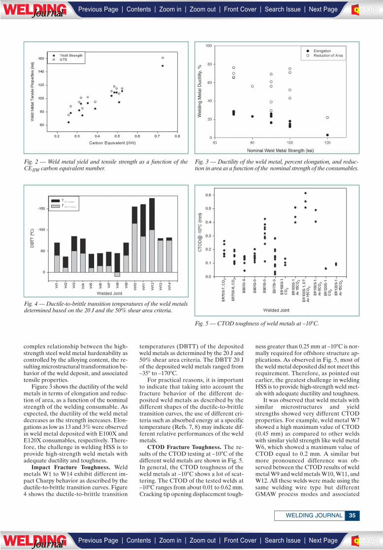
Fig. 2 — Weld metal yield and tensile strength as a function of theCEIIW carbon equivalent number.
Fig. 3 — Ductility of the weld metal, percent elongation, and reduc-tion in area as a function of the nominal strength of the consumables.
Fig. 4 — Ductile-to-brittle transition temperatures of the weld metalsdetermined based on the 20 J and the 50% shear area criteria.
Fig. 5 — CTOD toughness of weld metals at –10°C.
Wel
ding
Met
al D
uctil
ity, %
35WELDING JOURNAL
complex relationship between the high-strength steel weld metal hardenability ascontrolled by the alloying content, the re-sulting microstructural transformation be-havior of the weld deposit, and associatedtensile properties.
Figure 3 shows the ductility of the weldmetals in terms of elongation and reduc-tion of area, as a function of the nominalstrength of the welding consumable. Asexpected, the ductility of the weld metaldecreases as the strength increases. Elon-gations as low as 13 and 3% were observedin weld metal deposited with E100X andE120X consumables, respectively. There-fore, the challenge in welding HSS is toprovide high-strength weld metals withadequate ductility and toughness.
Impact Fracture Toughness. Weldmetals W1 to W14 exhibit different im-pact Charpy behavior as described by theductile-to-brittle transition curves. Figure4 shows the ductile-to-brittle transition
temperatures (DBTT) of the depositedweld metals as determined by the 20 J and50% shear area criteria. The DBTT 20 Jof the deposited weld metals ranged from–35° to –170°C.
For practical reasons, it is importantto indicate that taking into account thefracture behavior of the different de-posited weld metals as described by thedifferent shapes of the ductile-to-brittletransition curves, the use of different cri-teria such as absorbed energy at a specifictemperature (Refs. 7, 8) may indicate dif-ferent relative performances of the weldmetals.
CTOD Fracture Toughness. The re-sults of the CTOD testing at –10°C of thedifferent weld metals are shown in Fig. 5.In general, the CTOD toughness of theweld metals at –10°C shows a lot of scat-tering. The CTOD of the tested welds at–10°C ranges from about 0.01 to 0.62 mm.Cracking tip opening displacement tough-
ness greater than 0.25 mm at –10°C is nor-mally required for offshore structure ap-plications. As observed in Fig. 5, most ofthe weld metal deposited did not meet thisrequirement. Therefore, as pointed outearlier, the greatest challenge in weldingHSS is to provide high-strength weld met-als with adequate ductility and toughness.
It was observed that weld metals withsimilar microstructures and yieldstrengths showed very different CTODproperties. For example, weld metal W7showed a high maximum value of CTOD(0.45 mm) as compared to other weldswith similar yield strength like weld metalW6, which showed a maximum value ofCTOD equal to 0.2 mm. A similar butmore pronounced difference was ob-served between the CTOD results of weldmetal W9 and weld metals W10, W11, andW12. All these welds were made using thesame welding wire type but differentGMAW process modes and associated
| | | | | |Previous Page Contents Zoom in Zoom out Front Cover Search Issue Next PageLWE DINGJournalJournal BA
M SaGEF
| | | | | |Previous Page Contents Zoom in Zoom out Front Cover Search Issue Next PageLWE DINGJournalJournal BA
M SaGEF
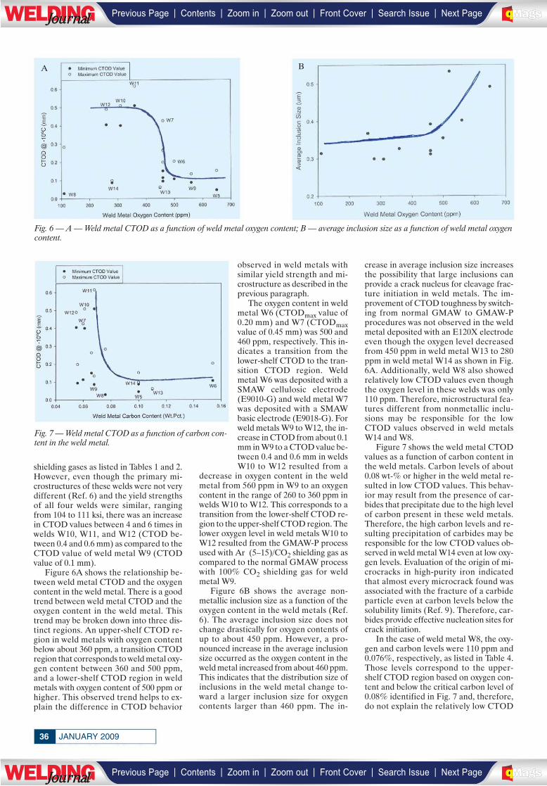
shielding gases as listed in Tables 1 and 2.However, even though the primary mi-crostructures of these welds were not verydifferent (Ref. 6) and the yield strengthsof all four welds were similar, rangingfrom 104 to 111 ksi, there was an increasein CTOD values between 4 and 6 times inwelds W10, W11, and W12 (CTOD be-tween 0.4 and 0.6 mm) as compared to theCTOD value of weld metal W9 (CTODvalue of 0.1 mm).
Figure 6A shows the relationship be-tween weld metal CTOD and the oxygencontent in the weld metal. There is a goodtrend between weld metal CTOD and theoxygen content in the weld metal. Thistrend may be broken down into three dis-tinct regions. An upper-shelf CTOD re-gion in weld metals with oxygen contentbelow about 360 ppm, a transition CTODregion that corresponds to weld metal oxy-gen content between 360 and 500 ppm,and a lower-shelf CTOD region in weldmetals with oxygen content of 500 ppm orhigher. This observed trend helps to ex-plain the difference in CTOD behavior
observed in weld metals withsimilar yield strength and mi-crostructure as described in theprevious paragraph.
The oxygen content in weldmetal W6 (CTODmax value of0.20 mm) and W7 (CTODmaxvalue of 0.45 mm) was 500 and460 ppm, respectively. This in-dicates a transition from thelower-shelf CTOD to the tran-sition CTOD region. Weldmetal W6 was deposited with aSMAW cellulosic electrode(E9010-G) and weld metal W7was deposited with a SMAWbasic electrode (E9018-G). Forweld metals W9 to W12, the in-crease in CTOD from about 0.1mm in W9 to a CTOD value be-tween 0.4 and 0.6 mm in weldsW10 to W12 resulted from a
decrease in oxygen content in the weldmetal from 560 ppm in W9 to an oxygencontent in the range of 260 to 360 ppm inwelds W10 to W12. This corresponds to atransition from the lower-shelf CTOD re-gion to the upper-shelf CTOD region. Thelower oxygen level in weld metals W10 toW12 resulted from the GMAW-P processused with Ar (5–15)/CO2 shielding gas ascompared to the normal GMAW processwith 100% CO2 shielding gas for weldmetal W9.
Figure 6B shows the average non-metallic inclusion size as a function of theoxygen content in the weld metals (Ref.6). The average inclusion size does notchange drastically for oxygen contents ofup to about 450 ppm. However, a pro-nounced increase in the average inclusionsize occurred as the oxygen content in theweld metal increased from about 460 ppm.This indicates that the distribution size ofinclusions in the weld metal change to-ward a larger inclusion size for oxygencontents larger than 460 ppm. The in-
crease in average inclusion size increasesthe possibility that large inclusions canprovide a crack nucleus for cleavage frac-ture initiation in weld metals. The im-provement of CTOD toughness by switch-ing from normal GMAW to GMAW-Pprocedures was not observed in the weldmetal deposited with an E120X electrodeeven though the oxygen level decreasedfrom 450 ppm in weld metal W13 to 280ppm in weld metal W14 as shown in Fig.6A. Additionally, weld W8 also showedrelatively low CTOD values even thoughthe oxygen level in these welds was only110 ppm. Therefore, microstructural fea-tures different from nonmetallic inclu-sions may be responsible for the lowCTOD values observed in weld metalsW14 and W8.
Figure 7 shows the weld metal CTODvalues as a function of carbon content inthe weld metals. Carbon levels of about0.08 wt-% or higher in the weld metal re-sulted in low CTOD values. This behav-ior may result from the presence of car-bides that precipitate due to the high levelof carbon present in these weld metals.Therefore, the high carbon levels and re-sulting precipitation of carbides may beresponsible for the low CTOD values ob-served in weld metal W14 even at low oxy-gen levels. Evaluation of the origin of mi-crocracks in high-purity iron indicatedthat almost every microcrack found wasassociated with the fracture of a carbideparticle even at carbon levels below thesolubility limits (Ref. 9). Therefore, car-bides provide effective nucleation sites forcrack initiation.
In the case of weld metal W8, the oxy-gen and carbon levels were 110 ppm and0.076%, respectively, as listed in Table 4.Those levels correspond to the upper-shelf CTOD region based on oxygen con-tent and below the critical carbon level of0.08% identified in Fig. 7 and, therefore,do not explain the relatively low CTOD
JANUARY 200936
Fig. 6 — A — Weld metal CTOD as a function of weld metal oxygen content; B — average inclusion size as a function of weld metal oxygencontent.
A B
Fig. 7 — Weld metal CTOD as a function of carbon con-tent in the weld metal.
| | | | | |Previous Page Contents Zoom in Zoom out Front Cover Search Issue Next PageLWE DINGJournalJournal BA
M SaGEF
| | | | | |Previous Page Contents Zoom in Zoom out Front Cover Search Issue Next PageLWE DINGJournalJournal BA
M SaGEF
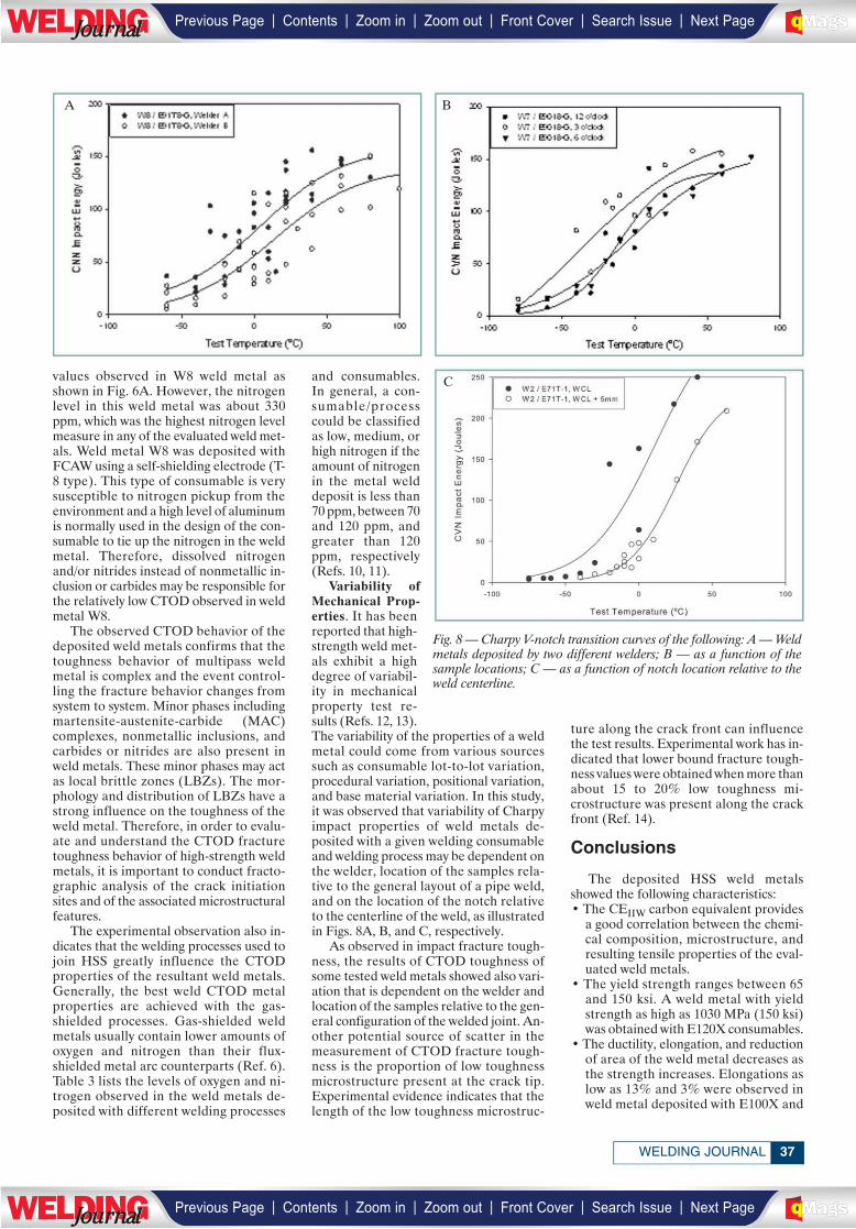
values observed in W8 weld metal asshown in Fig. 6A. However, the nitrogenlevel in this weld metal was about 330ppm, which was the highest nitrogen levelmeasure in any of the evaluated weld met-als. Weld metal W8 was deposited withFCAW using a self-shielding electrode (T-8 type). This type of consumable is verysusceptible to nitrogen pickup from theenvironment and a high level of aluminumis normally used in the design of the con-sumable to tie up the nitrogen in the weldmetal. Therefore, dissolved nitrogenand/or nitrides instead of nonmetallic in-clusion or carbides may be responsible forthe relatively low CTOD observed in weldmetal W8.
The observed CTOD behavior of thedeposited weld metals confirms that thetoughness behavior of multipass weldmetal is complex and the event control-ling the fracture behavior changes fromsystem to system. Minor phases includingmartensite-austenite-carbide (MAC)complexes, nonmetallic inclusions, andcarbides or nitrides are also present inweld metals. These minor phases may actas local brittle zones (LBZs). The mor-phology and distribution of LBZs have astrong influence on the toughness of theweld metal. Therefore, in order to evalu-ate and understand the CTOD fracturetoughness behavior of high-strength weldmetals, it is important to conduct fracto-graphic analysis of the crack initiationsites and of the associated microstructuralfeatures.
The experimental observation also in-dicates that the welding processes used tojoin HSS greatly influence the CTODproperties of the resultant weld metals.Generally, the best weld CTOD metalproperties are achieved with the gas-shielded processes. Gas-shielded weldmetals usually contain lower amounts ofoxygen and nitrogen than their flux-shielded metal arc counterparts (Ref. 6).Table 3 lists the levels of oxygen and ni-trogen observed in the weld metals de-posited with different welding processes
and consumables.In general, a con-sumable/processcould be classifiedas low, medium, orhigh nitrogen if theamount of nitrogenin the metal welddeposit is less than70 ppm, between 70and 120 ppm, andgreater than 120ppm, respectively(Refs. 10, 11).
Variability ofMechanical Prop-erties. It has beenreported that high-strength weld met-als exhibit a highdegree of variabil-ity in mechanicalproperty test re-sults (Refs. 12, 13).The variability of the properties of a weldmetal could come from various sourcessuch as consumable lot-to-lot variation,procedural variation, positional variation,and base material variation. In this study,it was observed that variability of Charpyimpact properties of weld metals de-posited with a given welding consumableand welding process may be dependent onthe welder, location of the samples rela-tive to the general layout of a pipe weld,and on the location of the notch relativeto the centerline of the weld, as illustratedin Figs. 8A, B, and C, respectively.
As observed in impact fracture tough-ness, the results of CTOD toughness ofsome tested weld metals showed also vari-ation that is dependent on the welder andlocation of the samples relative to the gen-eral configuration of the welded joint. An-other potential source of scatter in themeasurement of CTOD fracture tough-ness is the proportion of low toughnessmicrostructure present at the crack tip.Experimental evidence indicates that thelength of the low toughness microstruc-
ture along the crack front can influencethe test results. Experimental work has in-dicated that lower bound fracture tough-ness values were obtained when more thanabout 15 to 20% low toughness mi-crostructure was present along the crackfront (Ref. 14).
Conclusions
The deposited HSS weld metalsshowed the following characteristics:• The CEIIW carbon equivalent provides
a good correlation between the chemi-cal composition, microstructure, andresulting tensile properties of the eval-uated weld metals.
• The yield strength ranges between 65and 150 ksi. A weld metal with yieldstrength as high as 1030 MPa (150 ksi)was obtained with E120X consumables.
• The ductility, elongation, and reductionof area of the weld metal decreases asthe strength increases. Elongations aslow as 13% and 3% were observed inweld metal deposited with E100X and
37WELDING JOURNAL
Fig. 8 — Charpy V-notch transition curves of the following: A — Weldmetals deposited by two different welders; B — as a function of thesample locations; C — as a function of notch location relative to theweld centerline.
A B
C
| | | | | |Previous Page Contents Zoom in Zoom out Front Cover Search Issue Next PageLWE DINGJournalJournal BA
M SaGEF
| | | | | |Previous Page Contents Zoom in Zoom out Front Cover Search Issue Next PageLWE DINGJournalJournal BA
M SaGEF
E120X consumables, respectively. • The weld metals exhibit different im-
pact Charpy behavior. The DBTT 20 Jof the deposited weld metals rangefrom –35 to –170°C.
• The CTOD toughness of the weld met-als at –10°C shows a lot of scatteringand ranges from 0.01 to 0.62 mm. Weldmetal yield strength does not have aclear effect on CTOD toughness. Oxy-gen, carbon, and nitrogen levels in theweld metal greatly affect the CTODtoughness of the weld metal.
• The best CTOD toughness was ob-served in weld metals with oxygen, car-bon, and nitrogen levels ranging from260 to 360 ppm, 0.055 to 0.068%, and40 to 140 ppm, respectively. Generally,the best weld CTOD properties wereachieved with gas-shielded processes.
• Variability of Charpy impact and CTODtoughness of weld metals depositedwith a given welding consumable andwelding process was associated withwelder, location of the test samples rel-ative to the general layout of the weld,and to the location of the notch in thetest sample relative to the centerline ofthe weld.◆
References
1. Denys, R. 1994. The properties of
welded high strength steels. Revue De LaSoudure, pp. 26–39.
2. Dorling, D. V., Loyer, A., Russell,A. N., and Thompson, T. S. 1992. Gasmetal arc welding used in mainline 80 ksipipeline in Canada. Welding Journal 71(5):55–61.
3. Chaudhari, V., Ritzmann, H. P.,Wellnitz, G., Hillenbrand, H. G., and Will-ings, V. 1995. German gas pipeline first touse new generation line pipe. Oil and GasJournal, pp. 40–47, January 2.
4. Kawabata, F., Okatsu, M., Amano,K., and Nakano, Y. 1995. Metallurgicaland mechanical features of X100 line pipesteel. Pipeline Technology Vol. 2:263–271.
5. Hammond, J., and Millwood, N. A.2000. Construction of ultrahigh-strengthsteel pipelines. In Pipeline Technology, Pro-ceedings, 3rd International Conference,Brugge, Belgium, May 21–24, pp. 69–88.
6. Ramirez, J. E. 2008. Characteriza-tion of high-strength steel weld metals:chemical composition, microstructure,and nonmetallic inclusions. Welding Jour-nal 87(3): 65-s to 75-s.
7. Liu, S., and Olson, D. L. 2003. Weldmetal design: From flux coating to mi-crostructure. 6th International Trends inWelding Research Conference Proceedings,pp. 529–535.
8. NAVSEA Technical PublicationT9074-BC-GIB-010/200, Filler Materials
for Critical Applications Requirements forFlux-Cored Welding Electrodes, Bare Weld-ing Electrodes and Fluxes, and CoveredWelding Electrodes for Low-Alloy Steel Ap-plications.
9. Hertzberg, R. 1976. Deformation andFracture Mechanics of Engineering Materi-als. John Wiley & Sons, pp. 303, 341.
10. Wegrzyn, T. 2000. The Classifica-tion of Metal Weld Deposits in Terms of theAmount of Nitrogen. Proceedings, Tenth In-ternational Offshore and Polar EngineeringConference, Vol. 4, pp. 130–134.
11. Wegrzyn, T. 1996. Oxygen and ni-trogen in SMAW and GMAW processes.Proceedings, Sixth International Offshoreand Polar Engineering Conference, Vol. 4,pp. 166–168.
12. Denys, R. M. 1995. How much weldmetal yield strength do we need? PipelineTechnology Vol. 2: 555–563.
13. Denys, R. M., Lefevre, T., andGlover, A. G. 1995. Weld metal yieldstrength variability in pipeline girth welds.Pipeline Technology Vol. 2: 591–598.
14. Dolby, R. E. 1976. Factors control-ling weld toughness of weld metals. TheWelding Institute, Report 14/1976.
JANUARY 200938
| | | | | |Previous Page Contents Zoom in Zoom out Front Cover Search Issue Next PageLWE DINGJournalJournal BA
M SaGEF
| | | | | |Previous Page Contents Zoom in Zoom out Front Cover Search Issue Next PageLWE DINGJournalJournal BA
M SaGEF
_____________________________________________________
__________________
_______________
North America’s Largest Forming, Fabricating & Welding Event
November 15 – 18, 2009
North America’s largest metal forming, fabricating & welding trade show heads to
Chicago for 2009. Reach new markets and buyers located in one of the strongest
manufacturing regions of the country. Reserve your booth now! Space is
limited. Call today for exhibiting information.
(800) 443-9353www.aws.org/show
(800) 432-2832www.fmafabtech.com
(800) 733-3976www.sme.org/fabtech
(800) 541-5336www.metalform.com
cosponsored by
IncludingIncluding
industry partner
_______________ _________________ _________________ ________________
| | | | | |Previous Page Contents Zoom in Zoom out Front Cover Search Issue Next PageLWE DINGJournalJournal BA
M SaGEF
| | | | | |Previous Page Contents Zoom in Zoom out Front Cover Search Issue Next PageLWE DINGJournalJournal BA
M SaGEF
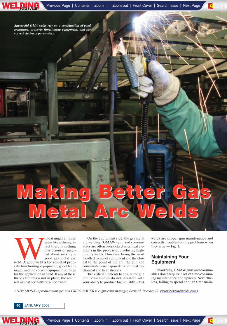
JANUARY 200940
While it might at timesseem like alchemy, infact there is nothingmysterious or magi-cal about making agood gas metal arc
weld. A good weld is the result of prop-erly functioning equipment, good tech-nique, and the correct equipment settingsfor the application at hand. If any of thesethree elements is not in place, the resultwill almost certainly be a poor weld.
On the equipment side, the gas metalarc welding (GMAW) gun and consum-ables are often overlooked as critical ele-ments in the process of producing high-quality welds. However, being the mosthandled pieces of equipment and the clos-est to the point of the arc, the gun andconsumables are exposed to continual me-chanical and heat stresses.
Two critical elements to ensure the gunand consumables do not interfere withyour ability to produce high-quality GMA
welds are proper gun maintenance andcorrectly troubleshooting problems whenthey arise — Fig. 1.
Maintaining YourEquipment
Thankfully, GMAW guns and consum-ables don’t require a lot of time-consum-ing maintenance and upkeep. Neverthe-less, failing to spend enough time main-
ANDY MONK is product manager and GREG BAUER is engineering manager, Bernard, Beecher, Ill. (www.bernardwelds.com).
Making Better GasMaking Better GasMetal Arc WeldsMetal Arc Welds
Successful GMA welds rely on a combination of goodtechnique, properly functioning equipment, and thecorrect electrical parameters.
| | | | | |Previous Page Contents Zoom in Zoom out Front Cover Search Issue Next PageLWE DINGJournalJournal BA
M SaGEF
| | | | | |Previous Page Contents Zoom in Zoom out Front Cover Search Issue Next PageLWE DINGJournalJournal BA
M SaGEF
_______________
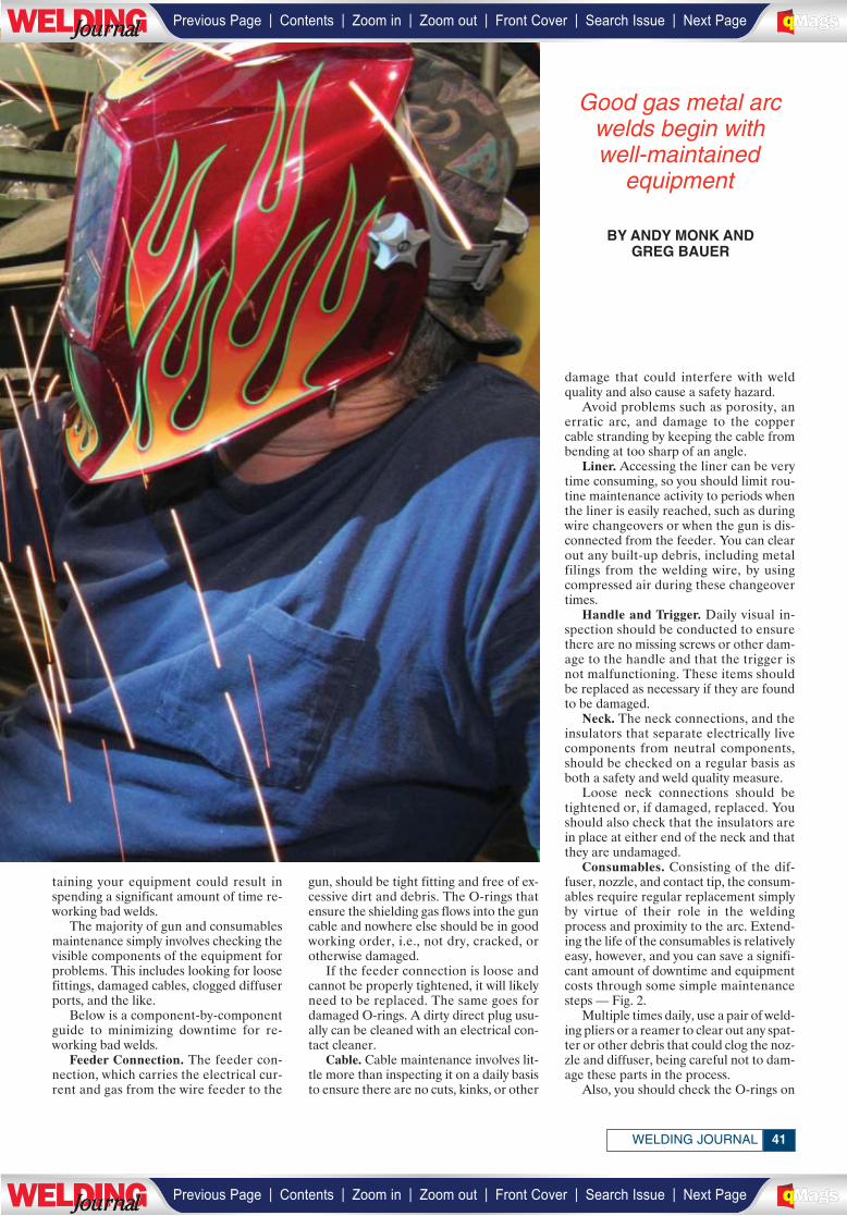
41WELDING JOURNAL
taining your equipment could result inspending a significant amount of time re-working bad welds.
The majority of gun and consumablesmaintenance simply involves checking thevisible components of the equipment forproblems. This includes looking for loosefittings, damaged cables, clogged diffuserports, and the like.
Below is a component-by-componentguide to minimizing downtime for re-working bad welds.
Feeder Connection. The feeder con-nection, which carries the electrical cur-rent and gas from the wire feeder to the
gun, should be tight fitting and free of ex-cessive dirt and debris. The O-rings thatensure the shielding gas flows into the guncable and nowhere else should be in goodworking order, i.e., not dry, cracked, orotherwise damaged.
If the feeder connection is loose andcannot be properly tightened, it will likelyneed to be replaced. The same goes fordamaged O-rings. A dirty direct plug usu-ally can be cleaned with an electrical con-tact cleaner.
Cable. Cable maintenance involves lit-tle more than inspecting it on a daily basisto ensure there are no cuts, kinks, or other
damage that could interfere with weldquality and also cause a safety hazard.
Avoid problems such as porosity, anerratic arc, and damage to the coppercable stranding by keeping the cable frombending at too sharp of an angle.
Liner. Accessing the liner can be verytime consuming, so you should limit rou-tine maintenance activity to periods whenthe liner is easily reached, such as duringwire changeovers or when the gun is dis-connected from the feeder. You can clearout any built-up debris, including metalfilings from the welding wire, by usingcompressed air during these changeovertimes.
Handle and Trigger. Daily visual in-spection should be conducted to ensurethere are no missing screws or other dam-age to the handle and that the trigger isnot malfunctioning. These items shouldbe replaced as necessary if they are foundto be damaged.
Neck. The neck connections, and theinsulators that separate electrically livecomponents from neutral components,should be checked on a regular basis asboth a safety and weld quality measure.
Loose neck connections should betightened or, if damaged, replaced. Youshould also check that the insulators arein place at either end of the neck and thatthey are undamaged.
Consumables. Consisting of the dif-fuser, nozzle, and contact tip, the consum-ables require regular replacement simplyby virtue of their role in the weldingprocess and proximity to the arc. Extend-ing the life of the consumables is relativelyeasy, however, and you can save a signifi-cant amount of downtime and equipmentcosts through some simple maintenancesteps — Fig. 2.
Multiple times daily, use a pair of weld-ing pliers or a reamer to clear out any spat-ter or other debris that could clog the noz-zle and diffuser, being careful not to dam-age these parts in the process.
Also, you should check the O-rings on
Good gas metal arcwelds begin with well-maintained
equipment
BY ANDY MONK ANDGREG BAUER
| | | | | |Previous Page Contents Zoom in Zoom out Front Cover Search Issue Next PageLWE DINGJournalJournal BA
M SaGEF
| | | | | |Previous Page Contents Zoom in Zoom out Front Cover Search Issue Next PageLWE DINGJournalJournal BA
M SaGEF
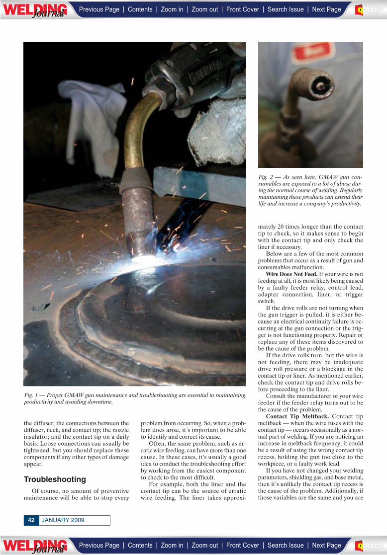
the diffuser; the connections between thediffuser, neck, and contact tip; the nozzleinsulator; and the contact tip on a dailybasis. Loose connections can usually betightened, but you should replace thesecomponents if any other types of damageappear.
TroubleshootingOf course, no amount of preventive
maintenance will be able to stop every
problem from occurring. So, when a prob-lem does arise, it’s important to be ableto identify and correct its cause.
Often, the same problem, such as er-ratic wire feeding, can have more than onecause. In these cases, it’s usually a goodidea to conduct the troubleshooting effortby working from the easiest componentto check to the most difficult.
For example, both the liner and thecontact tip can be the source of erraticwire feeding. The liner takes approxi-
mately 20 times longer than the contacttip to check, so it makes sense to beginwith the contact tip and only check theliner if necessary.
Below are a few of the most commonproblems that occur as a result of gun andconsumables malfunction.
Wire Does Not Feed. If your wire is notfeeding at all, it is most likely being causedby a faulty feeder relay, control lead,adapter connection, liner, or triggerswitch.
If the drive rolls are not turning whenthe gun trigger is pulled, it is either be-cause an electrical continuity failure is oc-curring at the gun connection or the trig-ger is not functioning properly. Repair orreplace any of these items discovered tobe the cause of the problem.
If the drive rolls turn, but the wire isnot feeding, there may be inadequatedrive roll pressure or a blockage in thecontact tip or liner. As mentioned earlier,check the contact tip and drive rolls be-fore proceeding to the liner.
Consult the manufacturer of your wirefeeder if the feeder relay turns out to bethe cause of the problem.
Contact Tip Meltback. Contact tipmeltback — when the wire fuses with thecontact tip — occurs occasionally as a nor-mal part of welding. If you are noticing anincrease in meltback frequency, it couldbe a result of using the wrong contact tiprecess, holding the gun too close to theworkpiece, or a faulty work lead.
If you have not changed your weldingparameters, shielding gas, and base metal,then it’s unlikely the contact tip recess isthe cause of the problem. Additionally, ifthose variables are the same and you are
JANUARY 200942
Fig. 1 — Proper GMAW gun maintenance and troubleshooting are essential to maintainingproductivity and avoiding downtime.
Fig. 2 — As seen here, GMAW gun con-sumables are exposed to a lot of abuse dur-ing the normal course of welding. Regularlymaintaining these products can extend theirlife and increase a company’s productivity.
| | | | | |Previous Page Contents Zoom in Zoom out Front Cover Search Issue Next PageLWE DINGJournalJournal BA
M SaGEF
| | | | | |Previous Page Contents Zoom in Zoom out Front Cover Search Issue Next PageLWE DINGJournalJournal BA
M SaGEF

confident you are not welding any closerto the material than normal, it may be timeto consider the work lead as the cause ofthe meltback. Repair or replace a faultywork lead as necessary.
A final cause of increased meltback, er-ratic wire feeding, is discussed as follows.
Erratic Wire Feeding. If the wire is notfeeding from the gun at a consistent rate,it is most likely being caused by the liner,drive rolls, or contact tip.
Begin troubleshooting an erraticallyfeeding wire by ensuring the contact tip isthe correct size for the wire being used,and that it is not damaged from excessivewear by the wire or from heat exposurefrom the arc.
If the contact tip is worn out from ex-cessive wear, it could be a result of thedrive rolls causing small deformities in thewire. After replacing the contact tip, besure to check for burrs or other abnormal-ities along the length of the wire and ad-just or replace the drive rolls as necessary.Drive rolls that are improperly tensioned,either too tight or too loose, can also leadto erratic wire feeding.
Erratic Arc. Interruptions in electricalconductivity are often the primary causeof an erratic arc. These are commonlycaused by the wire maintaining only inter-mittent contact with a worn out contacttip instead of the constant contact re-quired for a consistent arc. Simply replacethe worn out contact tip with a correctlysized new one if this proves to be the case.
Other possible causes of an erratic arc,all of which relate to inconsistent electri-cal conductivity, are a neck that is toostraight, a worn or kinked liner, debrisbuildup inside the liner, an improperlytrimmed liner, and a faulty work leadconnection.
Porosity. Holes in the weld bead, calledporosity, are almost always caused byproblems with the shielding gas coverage.This can be caused by excessive wind blow-ing the shielding gas away, worn out ordamaged diffusers, insulators, O-rings andfittings, a ruptured gas hose, too much ortoo little gas flow, or a faulty solenoid.
If porosity occurs without any changesto your work environment and equipmentsetup, troubleshoot the problem by check-ing all of the previously mentioned com-ponents and replacing as necessary.
Good gas metal arc welds are not aproduct of luck, and poor welds canusually be attributed to operator tech-nique, equipment malfunction, or incor-rect electrical parameters. Followingthese maintenance and troubleshootingtips won’t ensure excellent GMA welds,but will guarantee that your gun and con-sumables are not the cause of any prob-lems that arise.◆
43WELDING JOURNAL
For info go to www.aws.org/ad-index
For info go to www.aws.org/ad-index
| | | | | |Previous Page Contents Zoom in Zoom out Front Cover Search Issue Next PageLWE DINGJournalJournal BA
M SaGEF
| | | | | |Previous Page Contents Zoom in Zoom out Front Cover Search Issue Next PageLWE DINGJournalJournal BA
M SaGEF
____________________________
_______________
__________
______________
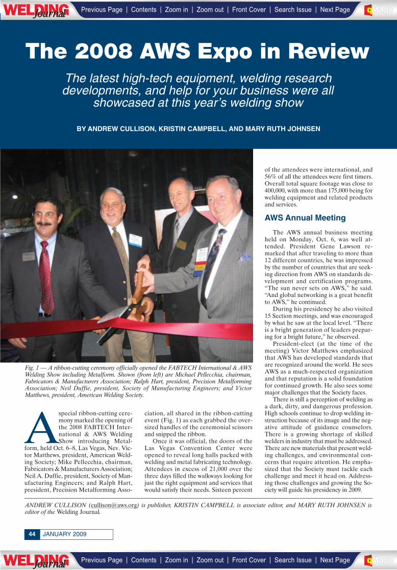
JANUARY 200944
Aspecial ribbon-cutting cere-mony marked the opening ofthe 2008 FABTECH Inter-national & AWS WeldingShow introducing Metal-
form, held Oct. 6–8, Las Vegas, Nev. Vic-tor Matthews, president, American Weld-ing Society; Mike Pellecchia, chairman,Fabricators & Manufacturers Association;Neil A. Duffie, president, Society of Man-ufacturing Engineers; and Ralph Hart,president, Precision Metalforming Asso-
ciation, all shared in the ribbon-cuttingevent (Fig. 1) as each grabbed the over-sized handles of the ceremonial scissorsand snipped the ribbon.
Once it was official, the doors of theLas Vegas Convention Center wereopened to reveal long halls packed withwelding and metal fabricating technology.Attendees in excess of 21,000 over thethree days filled the walkways looking forjust the right equipment and services thatwould satisfy their needs. Sixteen percent
of the attendees were international, and56% of all the attendees were first timers.Overall total square footage was close to400,000, with more than 175,000 being forwelding equipment and related productsand services.
AWS Annual Meeting
The AWS annual business meetingheld on Monday, Oct. 6, was well at-tended. President Gene Lawson re-marked that after traveling to more than12 different countries, he was impressedby the number of countries that are seek-ing direction from AWS on standards de-velopment and certification programs.“The sun never sets on AWS,” he said.“And global networking is a great benefitto AWS,” he continued.
During his presidency he also visited15 Section meetings, and was encouragedby what he saw at the local level. “Thereis a bright generation of leaders prepar-ing for a bright future,” he observed.
President-elect (at the time of themeeting) Victor Matthews emphasizedthat AWS has developed standards thatare recognized around the world. He seesAWS as a much-respected organizationand that reputation is a solid foundationfor continued growth. He also sees somemajor challenges that the Society faces.
There is still a perception of welding asa dark, dirty, and dangerous profession.High schools continue to drop welding in-struction because of its image and the neg-ative attitude of guidance counselors.There is a growing shortage of skilledwelders in industry that must be addressed.There are new materials that present weld-ing challenges, and environmental con-cerns that require attention. He empha-sized that the Society must tackle eachchallenge and meet it head on. Address-ing those challenges and growing the So-ciety will guide his presidency in 2009.
ANDREW CULLISON ([email protected]) is publisher, KRISTIN CAMPBELL is associate editor, and MARY RUTH JOHNSEN is editor of the Welding Journal.
The 2008 AWS Expo in ReviewThe latest high-tech equipment, welding researchdevelopments, and help for your business were all
showcased at this year’s welding show
BY ANDREW CULLISON, KRISTIN CAMPBELL, AND MARY RUTH JOHNSEN
Fig. 1 — A ribbon-cutting ceremony officially opened the FABTECH International & AWSWelding Show including Metalform. Shown (from left) are Michael Pellecchia, chairman,Fabricators & Manufacturers Association; Ralph Hart, president, Precision MetalformingAssociation; Neil Duffie, president, Society of Manufacturing Engineers; and VictorMatthews, president, American Welding Society.
___________
| | | | | |Previous Page Contents Zoom in Zoom out Front Cover Search Issue Next PageLWE DINGJournalJournal BA
M SaGEF
| | | | | |Previous Page Contents Zoom in Zoom out Front Cover Search Issue Next PageLWE DINGJournalJournal BA
M SaGEF
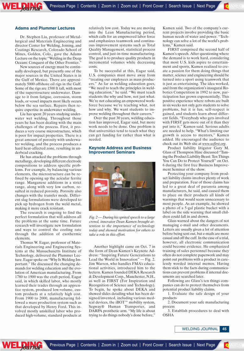
45WELDING JOURNAL
Adams and Plummer Lectures
Dr. Stephen Liu, professor of Metal-lurgical and Materials Engineering anddirector Center for Welding, Joining, andCoatings Research, Colorado School ofMines, Golden, Colo., gave the AdamsLecture on the topic “Welding in the DeepOceans: Conquest of the Other Frontier.”
New sources of energy must be contin-ually developed, but presently one of themajor sources in the United States is inthe Gulf of Mexico. There are approxi-mately 5000 offshore oil rigs in the Gulf.Some of the rigs are 1500 ft tall, with mostof the superstructure underwater. Dam-age to it from fatigue, corrosion, stormloads, or vessel impacts most likely occursbelow the sea surface. Repairs then re-quire expertise in underwater welding.
Liu has spent 20 years studying under-water wet welding. Throughout thoseyears he has been dealing with the mainchallenges of the process. First, it pro-duces a very coarse microstructure, whichis poor for impact properties. There is agreat amount of porosity with underwa-ter welding, and the process produces ahard heat-affected zone, resulting in un-derbead cracking.
He has attacked the problems throughmetallurgy, developing different electrodecompositions to address specific prob-lems. For example, by balancing variouselements, the microstructure can be re-fined by opening up the acicular ferriterange. Manganese additions in a strictrange, along with very low carbon, re-sulted in reduced porosity. Porosity alsochanges with the transfer mode. Differ-ent slag formulations were developed topick up hydrogen from the weld metal,making it more crack resistant.
The research is ongoing to find theperfect formulation that will address allthe problems at the same time. Future research will investigate new formulationand ways to control the cooling ratethrough the addition of exothermic elements.
Thomas W. Eagar, professor of Mate-rials Engineering and Engineering Sys-tems at the Massachusetts Institute ofTechnology, delivered the Plummer Lec-ture. Eagar spoke on “Why Is Welding Im-portant.” He discussed the changing de-mands for welding education and the evo-lution of American manufacturing. From1780 to 1900 was the craft period, Eagarsaid, in which skilled labor, who mostlylearned their trades through an appren-tice system, produced low-volume, cus-tom products at a relatively high cost.From 1900 to 2000, manufacturing fol-lowed a mass production system such asthat developed by Henry Ford. This in-volved mostly unskilled labor who pro-duced high-volume, standard products at
relatively low cost. Today we are movinginto the Lean Manufacturing period,which calls for an empowered labor forceand emphasizes teamwork and continu-ous improvement systems such as TotalQuality Management, statistical processcontrol, and just-in-time manufacturing.The goal is to produce quality products inincremental volumes while decreasingcosts.
To be successful at this, Eagar said,U.S. companies must move away from“treating our employees as mass produc-ers.” As far as welding education goes,“We need to teach the principles in weld-ing education,” he said. “We must teachstudents the why and how, not just what.We’re not educating an empowered work-force because we’re teaching what, nothow and why. We want students to im-prove welding throughout their careers.”
Over the past 30 years, welding educa-tion has improved, Eagar said, but morework needs to be done. One problem isthat universities tend to teach what theycan get funding for rather than what isneeded.
Keynote Address and BusinessImprovement Seminars
Another highlight came on Oct. 7 inthe form of Dean Kamen’s Keynote Ad-dress: “Inspiring Future Generations toLead the World in Innovation” — Fig. 2.Jim Warren, who handles FMA’s educa-tional activities, introduced him to thelectern. Kamen founded DEKA Research& Development Corp., Manchester, N.H.,as well as FIRST (For Inspiration andRecognition of Science and Technology).To begin, he spoke about DEKA andshowed slides detailing what has been de-signed/invented, including various med-ical devices, the iBOT™ mobility system,Segway® Human Transporter, andDARPA prosthetic arm. “My life is abouttrying to do things nobody’s done before,”
Kamen said. Two of the company’s cur-rent projects involve providing the basichuman needs of water and power. “Tech-nology can solve a lot of the world’s prob-lems,” Kamen said.
FIRST comprised the second half ofKamen’s speech. After questioning wherethe demand is to work hard, consideringthat most U.S. kids aspire to entertain-ment and sports, Kamen realized to cre-ate a passion for them doing things thatmatter, science and engineering should beturned into a sport using teamwork thatis just as entertaining. The idea worked,and from the organization’s inaugural Ro-botics Competition in 1992 to now, par-ticipation has grown exponentially. Thispositive experience where robots are builtin six weeks not only gets students to solveproblems, but it is fun, self-respect isgained, and students learn about differ-ent fields. “Everybody who gets involvedwith FIRST gets more out of it than theyput into it,” Kamen said. Serious adultsare needed to help. “What’s limiting ourgrowth is access to mentors,” Kamenadded. He encouraged the audience tocheck out its Web site at www.usfirst.org.
Product liability litigator Gary M.Glass of Thompson Hine discussed “Tam-ing the Product Liability Beast: Ten ThingsYou Can Do to Protect Yourself” on Oct.6 during the first free Business Improve-ment Seminar of the show.
Protecting your company from prod-uct liability claims involves plenty of workand preparation. Fear of those claims hasled to a great deal of paranoia amongmanufacturers, he said, and caused themto place on their products all kinds ofwarnings that would seem unnecessary tomost people. As an example, he showeda photo of a 5-gal plastic bucket with alabel on the side warning that small chil-dren could fall in and drown.
Glass warned about the dangers of notmanaging e-mail and other documents.Letters are usually given a lot of attentionbefore being sent out, but e-mails are morecasual and off the cuff. In the case of a trial,however, all electronic communicationcould become evidence. He emphasizedtraining of sales personnel because theyoften do not complete paperwork and maypoint out problems with a product in care-lessly worded internal memos. Havingthem stick to the facts during communica-tions can prevent problems if internal doc-uments are searched later.
Following are Glass’s ten things com-panies can do to protect themselves frompotential product liability claims.
1. Evaluate the safe design of yourproducts
2. Document your safe manufacturingprocess
3. Establish procedures to deal withOSHA
Fig. 2 — During his sprited speech to a largecrowd, innovator Dean Kamen brought at-tention to the importance of technologytoday and showed motivation for others totake a role in this effort.
| | | | | |Previous Page Contents Zoom in Zoom out Front Cover Search Issue Next PageLWE DINGJournalJournal BA
M SaGEF
| | | | | |Previous Page Contents Zoom in Zoom out Front Cover Search Issue Next PageLWE DINGJournalJournal BA
M SaGEF
_________
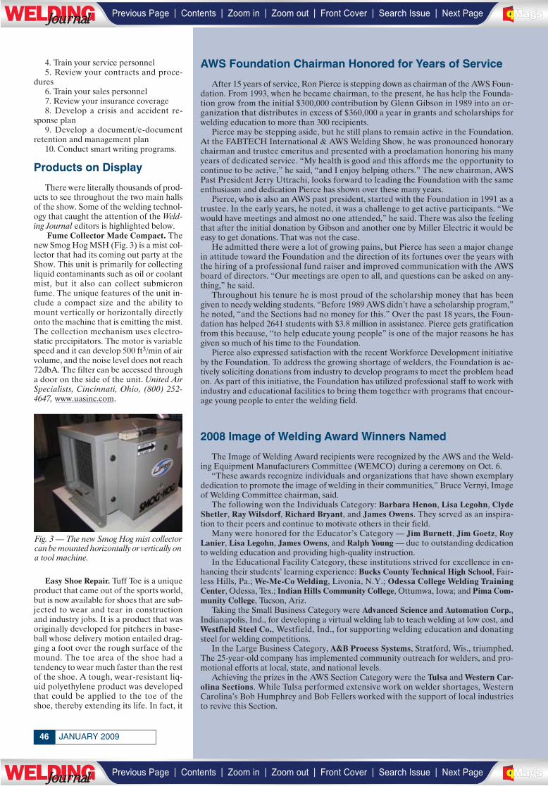
JANUARY 200946
4. Train your service personnel5. Review your contracts and proce-
dures6. Train your sales personnel7. Review your insurance coverage8. Develop a crisis and accident re-
sponse plan9. Develop a document/e-document
retention and management plan10. Conduct smart writing programs.
Products on Display
There were literally thousands of prod-ucts to see throughout the two main hallsof the show. Some of the welding technol-ogy that caught the attention of the Weld-ing Journal editors is highlighted below.
Fume Collector Made Compact. Thenew Smog Hog MSH (Fig. 3) is a mist col-lector that had its coming out party at theShow. This unit is primarily for collectingliquid contaminants such as oil or coolantmist, but it also can collect submicronfume. The unique features of the unit in-clude a compact size and the ability tomount vertically or horizontally directlyonto the machine that is emitting the mist.The collection mechanism uses electro-static precipitators. The motor is variablespeed and it can develop 500 ft3/min of airvolume, and the noise level does not reach72dbA. The filter can be accessed througha door on the side of the unit. United AirSpecialists, Cincinnati, Ohio, (800) 252-4647, www.uasinc.com.
Easy Shoe Repair. Tuff Toe is a uniqueproduct that came out of the sports world,but is now available for shoes that are sub-jected to wear and tear in constructionand industry jobs. It is a product that wasoriginally developed for pitchers in base-ball whose delivery motion entailed drag-ging a foot over the rough surface of themound. The toe area of the shoe had atendency to wear much faster than the restof the shoe. A tough, wear-resistant liq-uid polyethylene product was developedthat could be applied to the toe of theshoe, thereby extending its life. In fact, it
Fig. 3 — The new Smog Hog mist collectorcan be mounted horizontally or vertically ona tool machine.
AWS Foundation Chairman Honored for Years of Service
After 15 years of service, Ron Pierce is stepping down as chairman of the AWS Foun-dation. From 1993, when he became chairman, to the present, he has help the Founda-tion grow from the initial $300,000 contribution by Glenn Gibson in 1989 into an or-ganization that distributes in excess of $360,000 a year in grants and scholarships forwelding education to more than 300 recipients.
Pierce may be stepping aside, but he still plans to remain active in the Foundation.At the FABTECH International & AWS Welding Show, he was pronounced honorarychairman and trustee emeritus and presented with a proclamation honoring his manyyears of dedicated service. “My health is good and this affords me the opportunity tocontinue to be active,” he said, “and I enjoy helping others.” The new chairman, AWSPast President Jerry Uttrachi, looks forward to leading the Foundation with the sameenthusiasm and dedication Pierce has shown over these many years.
Pierce, who is also an AWS past president, started with the Foundation in 1991 as atrustee. In the early years, he noted, it was a challenge to get active participants. “Wewould have meetings and almost no one attended,” he said. There was also the feelingthat after the initial donation by Gibson and another one by Miller Electric it would beeasy to get donations. That was not the case.
He admitted there were a lot of growing pains, but Pierce has seen a major changein attitude toward the Foundation and the direction of its fortunes over the years withthe hiring of a professional fund raiser and improved communication with the AWSboard of directors. “Our meetings are open to all, and questions can be asked on any-thing,” he said.
Throughout his tenure he is most proud of the scholarship money that has beengiven to needy welding students. “Before 1989 AWS didn’t have a scholarship program,”he noted, “and the Sections had no money for this.” Over the past 18 years, the Foun-dation has helped 2641 students with $3.8 million in assistance. Pierce gets gratificationfrom this because, “to help educate young people” is one of the major reasons he hasgiven so much of his time to the Foundation.
Pierce also expressed satisfaction with the recent Workforce Development initiativeby the Foundation. To address the growing shortage of welders, the Foundation is ac-tively soliciting donations from industry to develop programs to meet the problem headon. As part of this initiative, the Foundation has utilized professional staff to work withindustry and educational facilities to bring them together with programs that encour-age young people to enter the welding field.
2008 Image of Welding Award Winners Named
The Image of Welding Award recipients were recognized by the AWS and the Weld-ing Equipment Manufacturers Committee (WEMCO) during a ceremony on Oct. 6.
“These awards recognize individuals and organizations that have shown exemplarydedication to promote the image of welding in their communities,” Bruce Vernyi, Imageof Welding Committee chairman, said.
The following won the Individuals Category: Barbara Henon, Lisa Legohn, ClydeShetler, Ray Wilsdorf, Richard Bryant, and James Owens. They served as an inspira-tion to their peers and continue to motivate others in their field.
Many were honored for the Educator’s Category — Jim Burnett, Jim Goetz, RoyLanier, Lisa Legohn, James Owens, and Ralph Young — due to outstanding dedicationto welding education and providing high-quality instruction.
In the Educational Facility Category, these institutions strived for excellence in en-hancing their students’ learning experience: Bucks County Technical High School, Fair-less Hills, Pa.; We-Me-Co Welding, Livonia, N.Y.; Odessa College Welding TrainingCenter, Odessa, Tex.; Indian Hills Community College, Ottumwa, Iowa; and Pima Com-munity College, Tucson, Ariz.
Taking the Small Business Category were Advanced Science and Automation Corp.,Indianapolis, Ind., for developing a virtual welding lab to teach welding at low cost, andWestfield Steel Co., Westfield, Ind., for supporting welding education and donatingsteel for welding competitions.
In the Large Business Category, A&B Process Systems, Stratford, Wis., triumphed.The 25-year-old company has implemented community outreach for welders, and pro-motional efforts at local, state, and national levels.
Achieving the prizes in the AWS Section Category were the Tulsa and Western Car-olina Sections. While Tulsa performed extensive work on welder shortages, WesternCarolina’s Bob Humphrey and Bob Fellers worked with the support of local industriesto revive this Section.
| | | | | |Previous Page Contents Zoom in Zoom out Front Cover Search Issue Next PageLWE DINGJournalJournal BA
M SaGEF
| | | | | |Previous Page Contents Zoom in Zoom out Front Cover Search Issue Next PageLWE DINGJournalJournal BA
M SaGEF
__________
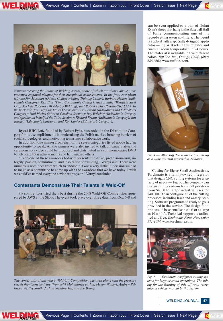
Rywal-RHC Ltd., founded by Robert Pyka, succeeded in the Distributor Cate-gory for its accomplishments in modernizing the Polish market, breaking barriers ofsocialist ideologies, and motivating teams into collaborative work.
In addition, one winner from each of the seven categories listed above had anopportunity to speak. All the winners were also invited to talk on-camera after theceremony so a video could be produced and distributed in a commemorative DVDto celebrate their achievements and help inspire others.
“Everyone of these awardees today represents the drive, professionalism, in-tegrity, passion, commitment, and inspiration for welding,” Vernyi said. There werenumerous nominees from which to choose. “It was a very difficult decision we hadto make as a committee to come up with the awardees that we have today. I wishwe could’ve named everyone a winner this year,” Vernyi concluded.
Contestants Demonstrate Their Talents in Weld-Off
Six competitors tried their best during the 2008 Weld-Off Competition spon-sored by AWS at the Show. The event took place over three days from Oct. 6–8 and
47WELDING JOURNAL
can be seen applied to a pair of NolanRyan’s shoes that hang in the Baseball Hallof Fame commemorating one of hisrecord-setting seven no-hitters. The liquidis applied with a specially designed appli-cator — Fig. 4. It sets in five minutes andcures at room temperature in 24 hours.The material is available in five differentcolors. Tuff Toe, Inc., Orange, Calif., (800)888-0802, www.tufftoe. com.
Cutting for Big or Small Applications.Torchmate is a family-owned integratorthat designs CNC cutting systems for a va-riety of needs — Fig. 5. The company candesign cutting systems for small job shopsfrom $4000 to larger industrial uses for$40,000. It can configure all of the cuttingprocesses, including laser and waterjet cut-ting. Software programmed ready to go isprovided in the service. The design foot-print could be as small as 4 × 4 ft or as largeas 10 × 40 ft. Technical support is unlim-ited and free. Torchmate, Reno, Nev., (866)571-1074, www.torchmate.com.
The contestants of this year’s Weld-Off Competition, pictured along with the pressurevessels they fabricated, are (from left) Mohammed Farhat, Mason Winters, Andrew Pel-lissier, Westley Smith, Joshua Steinbrecher, and Joe Young.
Fig. 4 — After Tuff Toe is applied, it sets upas a wear-resistant material in 24 hours.
Fig. 5 — Torchmate configures cutting sys-tems for large or small operations. The tub-ing for the framing of this off-road recre-ational vehicle was cut by this system.
Winners receiving the Image of Welding Award, some of which are shown above, werepresented engraved plaques for their exceptional achievements. In the front row (fromleft) are Jim Mosman (Odessa College Welding Training Center); Barbara Henon (Indi-viduals Category); Ken Bice (Pima Community College); Jack Laudig (Westfield SteelCo.); Michele Robbins (We-Me-Co Welding); and Robert Pyka (Rywal-RHC Ltd.). Inthe back row (from left) are James Owens and Lisa Legohn (Individuals and Educator’sCategory); Paul Phelps (Western Carolina Section); Ray Wilsdorf (Individuals Categoryand speaker on behalf of the Tulsa Section); Richard Bryant (Individuals Category); JimBurnett (Educator’s Category); and Roy Lanier (Educator’s Category).
| | | | | |Previous Page Contents Zoom in Zoom out Front Cover Search Issue Next PageLWE DINGJournalJournal BA
M SaGEF
| | | | | |Previous Page Contents Zoom in Zoom out Front Cover Search Issue Next PageLWE DINGJournalJournal BA
M SaGEF
_____________
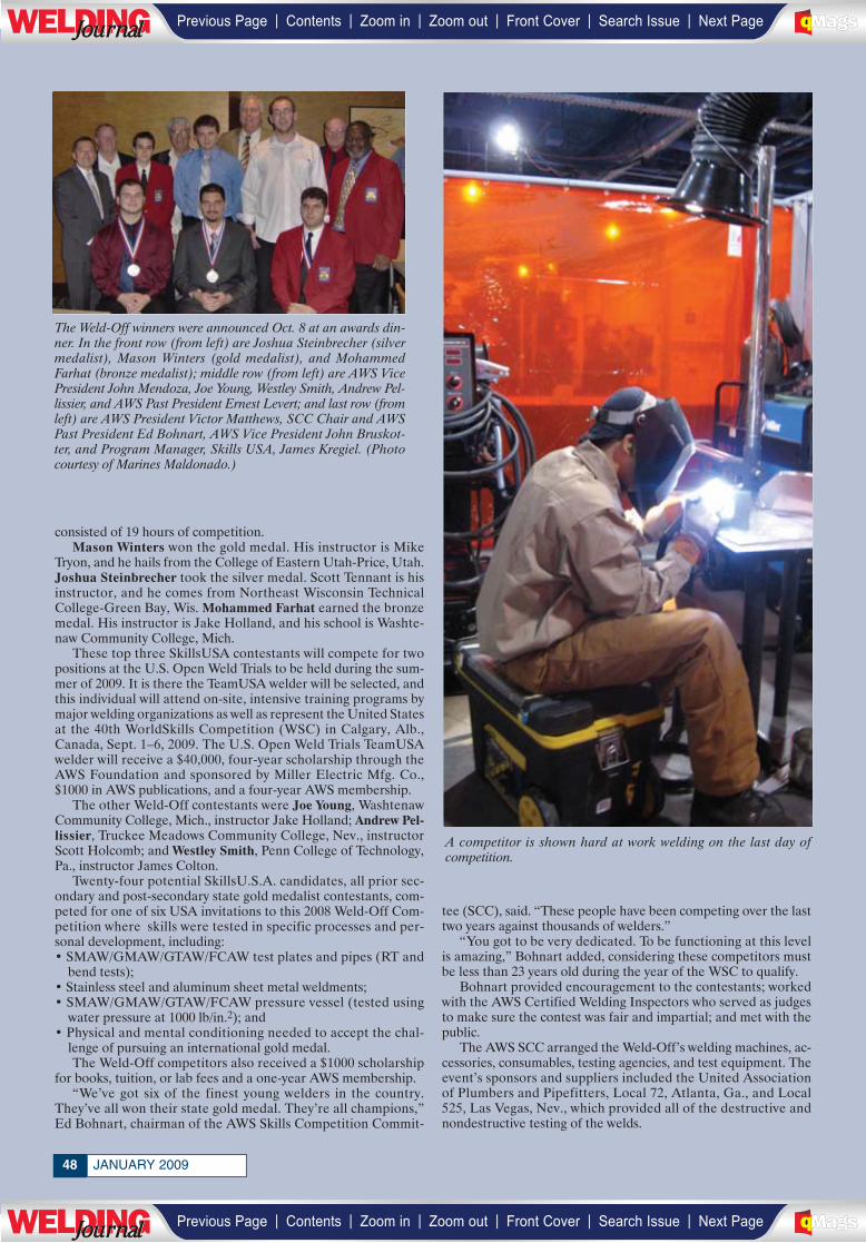
JANUARY 200948
consisted of 19 hours of competition.Mason Winters won the gold medal. His instructor is Mike
Tryon, and he hails from the College of Eastern Utah-Price, Utah.Joshua Steinbrecher took the silver medal. Scott Tennant is hisinstructor, and he comes from Northeast Wisconsin TechnicalCollege-Green Bay, Wis. Mohammed Farhat earned the bronzemedal. His instructor is Jake Holland, and his school is Washte-naw Community College, Mich.
These top three SkillsUSA contestants will compete for twopositions at the U.S. Open Weld Trials to be held during the sum-mer of 2009. It is there the TeamUSA welder will be selected, andthis individual will attend on-site, intensive training programs bymajor welding organizations as well as represent the United Statesat the 40th WorldSkills Competition (WSC) in Calgary, Alb.,Canada, Sept. 1–6, 2009. The U.S. Open Weld Trials TeamUSAwelder will receive a $40,000, four-year scholarship through theAWS Foundation and sponsored by Miller Electric Mfg. Co.,$1000 in AWS publications, and a four-year AWS membership.
The other Weld-Off contestants were Joe Young, WashtenawCommunity College, Mich., instructor Jake Holland; Andrew Pel-lissier, Truckee Meadows Community College, Nev., instructorScott Holcomb; and Westley Smith, Penn College of Technology,Pa., instructor James Colton.
Twenty-four potential SkillsU.S.A. candidates, all prior sec-ondary and post-secondary state gold medalist contestants, com-peted for one of six USA invitations to this 2008 Weld-Off Com-petition where skills were tested in specific processes and per-sonal development, including:• SMAW/GMAW/GTAW/FCAW test plates and pipes (RT and
bend tests);• Stainless steel and aluminum sheet metal weldments;• SMAW/GMAW/GTAW/FCAW pressure vessel (tested using
water pressure at 1000 lb/in.2); and• Physical and mental conditioning needed to accept the chal-
lenge of pursuing an international gold medal.The Weld-Off competitors also received a $1000 scholarship
for books, tuition, or lab fees and a one-year AWS membership.“We’ve got six of the finest young welders in the country.
They’ve all won their state gold medal. They’re all champions,”Ed Bohnart, chairman of the AWS Skills Competition Commit-
tee (SCC), said. “These people have been competing over the lasttwo years against thousands of welders.”
“You got to be very dedicated. To be functioning at this levelis amazing,” Bohnart added, considering these competitors mustbe less than 23 years old during the year of the WSC to qualify.
Bohnart provided encouragement to the contestants; workedwith the AWS Certified Welding Inspectors who served as judgesto make sure the contest was fair and impartial; and met with thepublic.
The AWS SCC arranged the Weld-Off’s welding machines, ac-cessories, consumables, testing agencies, and test equipment. Theevent’s sponsors and suppliers included the United Associationof Plumbers and Pipefitters, Local 72, Atlanta, Ga., and Local525, Las Vegas, Nev., which provided all of the destructive andnondestructive testing of the welds.
The Weld-Off winners were announced Oct. 8 at an awards din-ner. In the front row (from left) are Joshua Steinbrecher (silvermedalist), Mason Winters (gold medalist), and MohammedFarhat (bronze medalist); middle row (from left) are AWS VicePresident John Mendoza, Joe Young, Westley Smith, Andrew Pel-lissier, and AWS Past President Ernest Levert; and last row (fromleft) are AWS President Victor Matthews, SCC Chair and AWSPast President Ed Bohnart, AWS Vice President John Bruskot-ter, and Program Manager, Skills USA, James Kregiel. (Photocourtesy of Marines Maldonado.)
A competitor is shown hard at work welding on the last day of competition.
| | | | | |Previous Page Contents Zoom in Zoom out Front Cover Search Issue Next PageLWE DINGJournalJournal BA
M SaGEF
| | | | | |Previous Page Contents Zoom in Zoom out Front Cover Search Issue Next PageLWE DINGJournalJournal BA
M SaGEF
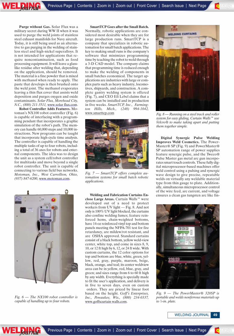
49WELDING JOURNAL
Purge without Gas. Solar Flux was amilitary secret during WW II when it wasused to purge the weld joints of stainlesssteel exhaust manifolds for Navy aircraft.Today, it is still being used as an alterna-tive to gas purging in the welding of stain-less steel and high-nickel superalloys. Itis not intended for applications that re-quire noncontamination, such as foodprocessing equipment. It will leave a glass-like residue after welding that, dependingon the application, should be removed.The material is a fine powder that is mixedwith methanol when ready to apply. Thepaste that develops is then brushed ontothe weld joint. The methanol evaporatesleaving a thin flux cover that assists welddeposition and purges oxygen and oxidecontaminants. Solar Flux, Morehead City,N.C., (888) 211-3511, www.solar flux.com.
Robot Controller Adds Features. Mo-toman’s NX100 robot controller (Fig. 6)is capable of interfacing with a program-ming pendant that incorporates a graphicsimulation of the robot’s path. The mem-ory can handle 60,000 steps and 10,000 in-structions. New programs can be taughtthat incorporate high-cycle time analysis.The controller is capable of handling themultiple tasks of up to four robots, includ-ing a total of 36 axes for robots and exter-nal components. The idea was to designthe unit as a system cell/robot controllerfor multitasks and move beyond a singlerobot controller. The unit is capable ofconnecting to various field bus networks.Motoman, Inc., West Carrollton, Ohio,(937) 847-6200, www.motoman.com.
SmartTCP Goes after the Small Batch.Normally, robotic applications are con-sidered most desirable when they are forlarge production runs. SmartTCP is acompany that specializes in robotic au-tomation for small batch applications. Thekey to making small runs is the company’ssoftware that minimizes programmingtime by teaching the robot to weld througha 3-D CAD model. The company claimsthat programming time is reduced enoughto make the welding of components insmall batches economical. The target ap-plications are industries with large or com-plex parts such as heavy industry, locomo-tives, shipyards, and construction. A com-plete gantry welding system is offered(Fig. 7), and CEO Efi Lebel claims that asystem can be installed and in productionin five weeks. SmartTCP, Inc., Farming-ton Hills, Mich., (248) 994-1042,www.smarttcp.com
Welding and Fabrication Curtains En-close Large Areas. Curtain Walls™ weredeveloped out of a need to protect workers from UV light — Fig. 8. And notonly is 100% UV light blocked, the curtainsalso confine welding fumes; feature rein-forced hems, chain-weighted bottoms,have 14-oz reinforced vinyl top and bottompanels meeting the NFPA-701 test for fireretardancy, are mildew/rot resistant, andare OSHA approved. Standard curtainsconsist of a black bottom, yellow weld-viewcenter, white top, and come in sizes 8, 9,10, or 12 ft high by 6, 12, or 24 ft wide. Withcustom curtains, the 12 color options fortop and bottom are blue, white, green, yel-low, red, gray, purple, maroon, beige,black, orange, and teal; its center weldviewarea can be in yellow, red, blue, gray, andgreen; and sizes range from 6 to 60 ft highby any width. Everything is specially madeto fit the user’s application, and delivery isin five to seven days, even on customorders. They are priced by linear foot
based on the height. Goff’s Enterprises,Inc., Pewaukee, Wis., (800) 234-0337,www.goffscurtain walls.com.
Digital Synergic Pulse Welding Improves Weld Cosmetics. The Power-Master® SP (Fig. 9) and PowerMaster®SP automation range of power suppliesfeature synergic pulse, and the Tweco®Pulse Master gas metal arc gun incorpo-rates smart touch controls. These fully dig-ital microprocessor-based machines offerweld control using a pulsing and synergicwave design to give precise, repeatablewelds on virtually any weldable materialtype from thin gauge to plate. Addition-ally, simultaneous microprocessor controlof the wire feed, arc current, and voltageensures a clean gas tungsten arc like fin-
Fig. 6 — The NX100 robot controller is capable of handling up to four robots.
Fig. 7 — SmartTCP offers complete au-tomation systems for small batch roboticapplications.
Fig. 8 — Running on a steel track and rollersystem for easy gliding, Curtain Walls™ useVelcro® to make taking apart and puttingthem together simple.
Fig. 9 — The PowerMaster® 320SP isportable and welds nonferrous materials upto 1⁄4-in. plate.
| | | | | |Previous Page Contents Zoom in Zoom out Front Cover Search Issue Next PageLWE DINGJournalJournal BA
M SaGEF
| | | | | |Previous Page Contents Zoom in Zoom out Front Cover Search Issue Next PageLWE DINGJournalJournal BA
M SaGEF
____________
____________
_____________
_________________
JANUARY 200950
ished appearance on aluminum alloys withgas metal arc welding productivity. Thisequipment includes technologies such asSmart MIG™; TwinPulse™; HDP™ (HighDefinition Pulse); HSP™ (High SpeedPulse); EasyLink™; SmartLogic™;JobTool™; TipTronic™; and FTT™ (FreshTip Treatment). In particular, the Power-Master® 320SP is complete with 320-Amaximum output, 4-roll wire feed system,33/44-lb spool capacity, 77-lb weight, and29.3 × 13.4 × 19.6 in. dimensions — Fig. 9.The PowerMaster® 400SP offers a maxi-mum output of 400 A and is available intwo configurations — as a fully integratedversion or a separate remote feeder sys-tem. The integrated variant has a 4-rollwire drive system and is supplied standardwith running gear. This product weighs215 lb, and its dimensions are 43.9 × 17.5× 33.7 in. Push/pull systems for produc-tion welding with 3⁄64-in. aluminum wirescan be run. Thermal Arc®, St. Louis, Mo.,(800) 426-1888, www.thermalarc.com.
Plasma System Features 45-A OutputCurrent and 50% Duty Cycle. The Power-max45® is a portable plasma cutting andgouging system — Fig. 10. It offers a rec-ommended ½-in. cut capacity and 1-in.severance; for gouge capacity, the metalremoved per hour is 6.2 lb. This single-gassystem (air or nitrogen) is designed forhand-held and mechanized applications.It cuts stainless steel, copper, and alu-minum. The 37-lb product is useful inHVAC duct cutting, truck and trailer fab-rication, and facility and equipment main-tenance of all types. Other highlights areas follows: Conical Flow™; patented drag-cutting technology; Boost Conditioner™;CNC interface and Fast Connect™ torchconnection; and Powercool™. Standardsystem components include a power sup-ply; T45v hand torch or T45m machinetorch; extra consumables for cutting andgouging; 20-ft work cable with clamp; andcarry strap. Development came throughmarket research, talking with plasma endusers, and working with an engineeringteam for its design. The list price is $2019.Hypertherm, Inc., Hanover, N.H., (800)643-0030, www.powerfulplasma.com.
Multipurpose Welding Machine Givesa Smooth Arc. The MultiMaster® 300Xis a ready-to-weld package offering goodperformance for gas metal arc, DC gastungsten arc, and covered electrode weld-ing — Fig. 11. An improvement on the 260model, it presents a more conventional-style machine. In addition, this product isoptimized for use with the company’sDual Shield X series of flux cored wireand is beneficial for welders currentlyusing shielded metal arc welding whowould like to use flux cored wire. ESAB’sproprietary Super Switch™ technologyfeatures a high-speed, solid-state powercontrol. The machine offers DC weldingoutput from 15 to 300 A at 40% duty cycle.Extra qualities include fan on demand, aheavy-duty four-drive roll stand with ser-rated Dual Shield X series wires in 0.045-and 0.052-in. diameters, a 400-A, 15-ft gunsetup for the same diameters, a large-capacity tool box, and an “easy-on” cylin-der tray. Also, the package contains apower source, built-in four-roll wirefeeder, factory-installed undercarriageand cylinder rack, torch, contact tips, reg-ulator/flowmeter, electrode holder andplug, and all necessary hoses and cables.The cost is about $4000. ESAB Welding &Cutting Products, Florence, S.C., (800) 372-2123, www.esab.com.
Just Grip, Roll, and Go to AchieveCritical Temperature Measurements. TheTempilstik-Pro™ is a fast, easy-to-use, andaccurate temperature indicator — Fig. 12.The product features a thumb-wheel ad-vancement and retraction system thatmakes advancing the chalk as easy as mov-ing your thumb, and this can be done with-
out taking your gloves off; no fumbling ordropping should occur. Developmentcame through talking to welders who saidindicators were hard to use with theirgloves on. One quick swipe of this patent-pending product across the surface and,when it melts it gives an instant, accurateindication that the rated temperature hasbeen reached. It is beneficial for weldersworking on critical applications such aspressure vessels, offshore oil rig fabrica-tion, pipeline construction, and architec-tural and structural projects. It meltswithin ± 1% of rated temperature. Thetemperature ranges available are from100° to 700°F. Tempil°, S. Plainfield, N.J.,(800) 757-8301, www.tempil.com.
Small Cell Teaches Students to Pro-gram Robots. Since many companies areaddressing work force issues through au-tomation, many schools are finding it nec-essary to include automation program-ming in their curriculums. In order to ad-dress the need to teach students robot pro-gramming, The Lincoln Electric Co. part-nered with FANUC Robotics to offer acompact Education Cell designed for ed-ucational institutions, training depart-ments, and other facilities interested inteaching robotic programming for gasmetal arc welding — Fig. 13. The cellmeasures 81 in. tall × 27 in. wide × 65 in.long and is on casters. It can fit through astandard doorway and be moved easilyfrom classroom to classroom. No specialpower is needed; it can be plugged intosingle-phase power. Everything neededfor operation is included: a Lincoln PowerWave® 355M welding power source andAutoDrive™ 4R90 wire feeder; FANUCArc Mate 50iC/5L robot with R30iA Matecontroller and teach pendant; integratedgas cylinder; fume extraction mounting;integrated safety measures; and a numberof FANUC software options. List price ofthe Robotic Education Cell is$35,000–$40,000. The Lincoln Electric Co.,Cleveland, Ohio, (216) 383-2667,www.lincolnelectric.com.
Fig. 10 — Users of Powermax45®, shownin action above, will benefit from its easyuse, good cut quality, and long consumablelife.
Fig. 11 — As a single-phase unit, the Mul-tiMaster® 300X is useful for medium tosmall shops. It offers easy setup.
Fig. 12 — Stroke the workpiece during heat-ing, and Tempilstik-Pro™ will make a dis-tinct mark by melting at the point of contactonce the surface reaches the product’s ratedtemperature.
| | | | | |Previous Page Contents Zoom in Zoom out Front Cover Search Issue Next PageLWE DINGJournalJournal BA
M SaGEF
| | | | | |Previous Page Contents Zoom in Zoom out Front Cover Search Issue Next PageLWE DINGJournalJournal BA
M SaGEF
_________
______________
___________
_________________
________________

SMAW Electrodes Were BoilermakerTested. The company’s new Boilermakerline of low-alloy shielded metal arc elec-trodes were developed specifically forwater wall tube repairs. They provide lowspatter levels and a good bead wash. Thefour electrodes — Boilermaker 18 (AWSE7018), Boilermaker A1 (E7018-A1),Boilermaker B2 (E8018-B2), and Boiler-maker B3 (E9018-B3) — were then givento journeymen from Boilermaker Local108 to use and evaluate, hence the name— Fig. 14. Five hundred pounds of theelectrodes were given to a power plant asa test, company representatives said, and100% of the welds made with them wereX-rayed. The normal reject rate is 7%, butthe welds made with the new electrodeshad a reject rate of 4.3%. The B2 elec-trodes are available in 3⁄32-in.diameter and12-in. lengths. The length allows welders
to bend the electrode so it can be used inthe tight spaces common to boiler tube re-pairs and allows for nonstop welding, less-ening the chance of starting and stoppingporosity. The other electrodes are avail-able in 3⁄32- and 1⁄8-in. diameters and in 14-in. lengths. Hobart Brothers Co., Troy,Ohio, (800) 424-1543, www.hobartbrothers.com.
Cordless Band Saw Can Be Held One-Handed. The STX-250C-NB portableband saw weighs 9 lb with the 18-V nickelcadmium battery in place. It allows theuser to safely make overhead cuts whilestanding on a ladder or scaffolding. Thesaw has a cutting capacity of 2½ in. andcan cut steel, stainless steel, aluminum,plastic, PVC, wood, and a variety of othermaterials. It features a 21,000 rev/min,heavy-duty DC motor and a bimetal blade.The saw lists for $319. Options are a $79kit that includes a nylon tool bag, extrablade, two batteries, and a safety shieldand the ST-CS250 cutting station that pro-vides a stable platform on which to use thesaw. As a safety feature, when the saw isput into the station, a magnetic overridedisables the saw’s switch and it then mustbe turned on and off using the station’slockout switch. The band saw and cuttingstation together weigh 19 lb — Fig. 15.Stout Tool Corp., Wixom, Mich., (877) 337-8688, www.stouttool.com.
Brake Stops Grinding Wheel Faster.The company now offers two new modelsof 5- and 6-in. grinders with a mechanicaldisc brake that stops the wheel in 3 s afterthe grinder is switched off. This reducesthe risk of accidents caused by a still-turn-ing wheel. At this time, the brake is onlyavailable on the WB11-125 Quick andWB11-150 Quick models of the com-pany’s Metal Masters line, but Vice Pres-ident David Smith said plans are to even-tually put it on all the models that includea dead man’s switch. Other improvementsto the line include a change from a single-to a double-sealed bearing for better dura-bility and more resistance to overload, a
fully encapsulated switch, almost totallyenclosed carbon brushes to keep grindingdust out of the motor, and a 25% in-creased air flow. Metabo, West Chester, Pa.,(800) 638-2264, www.metabousa.com.
Cleaning with Dry Ice. The company’snew Aero Series dry ice blast cleaning sys-tems were designed to use less air and lessdry ice while offering more aggressivecleaning action. They can remove greases,dirt, and oils that could present problemsfor welding. The line includes the Aero40, the most commonly used size; Aero80-DX (Fig. 16), the most aggressivecleaner with a high blast pressure; and theAero C100, a fully pneumatic modelgeared toward the contractor market.These machines all have larger hoppersthan previous models (the numbers in themodel names indicate the number ofpounds of dry ice their hoppers can hold).Each machine features the company’spatented SureFlow System that allows useof a full load without clogging, 360-deg ra-dius mobility, and all-terrain, no-flatwheels. The Models 40 and 80 feture trig-ger-activated hopper agitations and theC100 offers automated hopper agitationas well as twice the hose length of previ-ous pneumatic models (up to 100 ft). Thecompany offers more than 100 cleaningnozzles for the machines and they can becustom designed for a particular applica-tion. Cold Jet, LLC, Loveland, Ohio, (800)337-9423, www.coldjet.com.
See You Next Year
Start planning now to see the largestcollection of welding and metalworkingequipment and supplies under one roofin North America at the 2009 FABTECHInternational & AWS Welding Show inChicago, Ill., Nov. 15–18. For more infor-mation, visit www.aws.org/expo/.
51WELDING JOURNAL
Fig. 13 — This small-sized robot weldingcell can be wheeled from one classroom toanother to train students about robot pro-gramming.
Fig. 14 — Journeymen from BoilermakerLocal 108 tested Hobart’s new SMAW elec-trodes and offered their input on how wellthey performed water wall tube repairs.
Fig. 15 — Stout Tool’s cordless, hand-heldband saw can be used on its own or placedinto the optional cutting station as shownhere.
Fig. 16 — The Aero 80-DX dry ice blastcleaning system from Cold Jet offers a blastpressure range of 30–140 lb/in.2 for aggres-sive cleaning action.
| | | | | |Previous Page Contents Zoom in Zoom out Front Cover Search Issue Next PageLWE DINGJournalJournal BA
M SaGEF
| | | | | |Previous Page Contents Zoom in Zoom out Front Cover Search Issue Next PageLWE DINGJournalJournal BA
M SaGEF
____________
___________
_____
______________
____________
____________
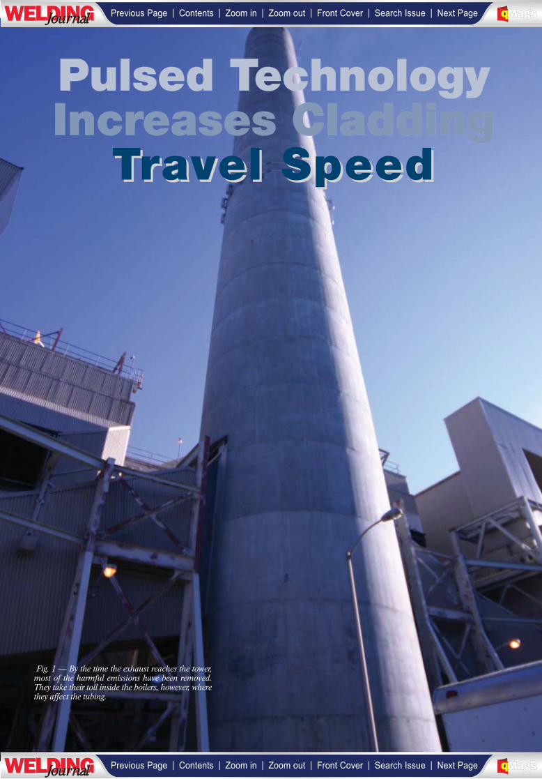
Pulsed TechnologyIncreases Cladding
Travel SpeedTravel Speed
Fig. 1 — By the time the exhaust reaches the tower,most of the harmful emissions have been removed.They take their toll inside the boilers, however, wherethey affect the tubing.
| | | | | |Previous Page Contents Zoom in Zoom out Front Cover Search Issue Next PageLWE DINGJournalJournal BA
M SaGEF
| | | | | |Previous Page Contents Zoom in Zoom out Front Cover Search Issue Next PageLWE DINGJournalJournal BA
M SaGEF
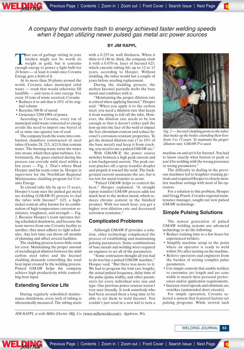
53WELDING JOURNAL
That can of garbage sitting in yourkitchen might not be worth itsweight in gold, but it contains
enough energy to power a light bulb for24 hours — at least it could once CovantaEnergy gets a hold of it.
At its more than 30 plants around theworld, Covanta takes municipal solidwaste — trash that would otherwise filllandfills — and turns it into energy. Forevery 10 tons of waste received, Covanta• Reduces it to ash that is 10% of its orig-
inal volume• Recycles 500 lb of metal• Generates 5200 kWh of power.
According to Covanta, every ton ofmunicipal solid waste converted to energyavoids the need to import one barrel ofoil or mine one-quarter ton of coal.
The company feeds the waste into com-bustion chambers constructed of steeltubes (Grades 28, 213, A213) that containwater. The burning waste turns the waterinto steam, which then spins turbines. Un-fortunately, the gases emitted during theprocess can corrode mild steel within afew years — Fig. 1. That’s where BradHooper and his team come in. Hooper issupervisor for the NorthEast RegionalMaintenance cladding program for Cov-anta Energy.
To extend tube life by up to 15 years,Hooper’s team uses the pulsed gas metalarc welding (GMAW-P) process to cladthe tubes with Inconel™ 625, a high-nickel-content alloy known for its combi-nation of high-temperature corrosion re-sistance, toughness, and strength — Fig.2. Because Hooper’s team operates dur-ing scheduled shutdowns, and because theteam moves from one Covanta facility toanother, they must adhere to tight sched-ules. Any lost time can throw off monthsof planning and affect several facilities.
The cladding process leaves little roomfor error. Maintaining the proper amountof metallurgical dilution between the mildcarbon steel tubes and the Inconelcladding demands controlling the totalheat input created by the welding process.Pulsed GMAW helps the companyachieve high productivity while control-ling heat input.
Extending Service Life
During regularly scheduled mainte-nance shutdowns, every inch of tubing isultrasonically measured. The tubing starts
with a 0.235-in. wall thickness. When itthins to 0.140 in. thick, the company cladsit with a 0.070-in. layer of Inconel 625,which extends tubing life up to 12 to 15years, according to Hooper. Withoutcladding, the tubes would last a couple ofyears before needing replacement.
During the cladding process, themolten Inconel partially melts the basemetal and combines with it.
“Maintaining the proper dilution rateis critical when applying Inconel,” Hoopersaid. “When you apply it to the carbonsteel, you need a dilution rate that keepsit from wanting to fall off the tube. How-ever, the dilution rate needs to be lowenough so that it doesn’t either pull theiron up into the face of the weld or impactthe free chromium content and reduce In-conel’s corrosion-resistant properties. Toget the desired dilution rate (7 to 10% ofthe base metal) and keep it from crack-ing, you need to use a pulsed GMAW arc.”
With GMAW-P, the power sourceswitches between a high peak current anda low background current. The peak cur-rent pinches off a spray transfer dropletand propels it toward the weld. The back-ground current maintains the arc, but istoo low for metal transfer to occur.
“Pulsed GMAW helps to control theheat,” Hooper explained. “A straight(spray transfer) GMAW process adds toomuch heat to the molten metal, which re-duces chrome content in the finishedproduct. With too much heat, you get ahigher iron dilution rate and decreasedcorrosion resistance.”
Complicated Problems
Although GMAW-P provides a solu-tion, older technology complicated theprocess of establishing and maintainingpulsing parameters. Some combinationsof base metals and welding wires requiredan engineer to set all of the parameters.
“Some contractors thought all you hadto do was buy a pulsed GMAW machine,”Hooper said. “But there was more to it.We had to program the trim (arc length),the actual pulsed frequency, delay time ofthe pulse (pulse width), and other param-eters for every individual wire size andtype. Our previous power sources weren’tvery user-friendly. It took somebody whohad been around them a long time to beable to set them to weld Inconel. Youcouldn’t just send in a new kid to turn a
machine on and set it for Inconel. You hadto know exactly what button to push oryou’d be welding with the wrong processesor wrong parameters.”
The difficulty in dialing in the previ-ous machines led to lengthier training pe-riods and required Hooper to closely mon-itor machine settings with most of his op-erators.
For a solution to this problem, Hooperand Gregg Pruett, Covanta regional main-tenance manager, sought out new pulsedGMAW technology.
Simple Pulsing Solutions
The newest generation of pulsedGMAW welding systems use advancedtechnology to do the following:• Reduce training time to a few hours for
experienced welders.• Simplify machine setup to the point
where an operator is ready to weldwithin 30 s after turning on the machine.
• Relieve operators and engineers fromthe burden of setting complex pulse parameters.
• Use simple controls that enable weldersto customize arc length and arc conewidth to match their personal prefer-ences and/or application requirements.
• Increase travel speeds and eliminate arcrestrikes (unintended short circuits).For simple operation, Covanta se-
lected a system that featured factory-setpulsing programs. While several such
JIM RAPPL is with Miller Electric Mfg. Co. (www.millerwelds.com), Appleton, Wis.
A company that converts trash to energy achieved faster welding speeds when it began utilizing newer pulsed gas metal arc power sources
BY JIM RAPPL
Fig. 2 — Inconel cladding protects the tubesthat make up the boiler, extending their livesfrom 3 to 15 years. To maintain the properdilution rate, GMAW-P is used.
| | | | | |Previous Page Contents Zoom in Zoom out Front Cover Search Issue Next PageLWE DINGJournalJournal BA
M SaGEF
| | | | | |Previous Page Contents Zoom in Zoom out Front Cover Search Issue Next PageLWE DINGJournalJournal BA
M SaGEF
______________
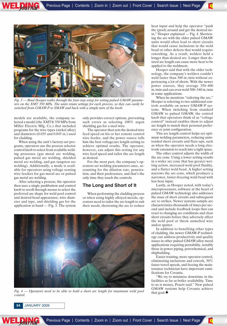
JANUARY 200954
models are available, the company se-lected a model (the XMT® 350 MPa fromMiller Electric Mfg. Co.) that includedprograms for the wire types (nickel alloy)and diameters (0.035 and 0.045 in.) usedfor cladding.
When using the unit’s factory-set pro-grams, operators use the process selectorcontrol knob to select from available weld-ing processes (gas metal arc welding,pulsed gas metal arc welding, shieldedmetal arc welding, and gas tungsten arcwelding). Additionally, a mode is avail-able for operators using voltage sensingwire feeders for gas metal arc or pulsedgas metal arc welding.
After selecting a process, the operatorthen uses a single pushbutton and controlknob to scroll through menus to select thepreferred arc shape for weld pool controland desired bead appearance, wire diam-eter and type, and shielding gas for theapplication at hand — Fig. 3. The system
only provides correct options, preventingsuch errors as selecting 100% argonshielding gas for a steel wire.
The operator then sets the desired wirefeed speed on his or her remote controlwire feeder, and the power source tellshim the best voltage/arc length setting toachieve optimal results. The operator,however, can adjust this setting for anywire feed speed and tailor the arc lengthas desired.
For the most part, the company’s op-erators set welding parameters once, ac-counting for the dilution rate, penetra-tion, and their preferences, and that’s theonly time they touch the controls.
The Long and Short of It
When performing the cladding processor when using highly alloyed metals, op-erators need to tailor the arc length to suittheir needs, shortening the arc to reduce
heat input and help the operator “pushthe (pool) around and get the desired tie-in,” Hooper explained — Fig. 4. Shorten-ing the arc with the older pulsed GMAWunits would often lead to short circuitsthat would cause inclusions in the weldbead or other defects that would requirereworking. As a result, welders held alonger than desired arc. Longer than de-sired arc length can cause more heat to beapplied to the weldment.
Hooper said that with the older tech-nology, the company’s welders couldn’tweld faster than 300 in./min without ex-periencing a lot of shorts. With the newerpower sources, they average 350–400in./min and can even weld 500–540 in./minin some applications.
When he mentions “tailoring the arc,”Hooper is referring to two additional con-trols available on newer GMAW-P sys-tems. When switching from standardGMAW to pulsed GMAW, the controlknob that operators think of as “voltagecontrol” instead enables them to adjustarc length to match their personal prefer-ence or joint configuration.
This arc length control helps set opti-mum welding parameters, reducing unin-tended short circuits and flare-ups, suchas when the operator needs a long elec-trode extension to reach into a tight space.
The other control adjusts the width ofthe arc cone. Using a lower setting resultsin a wider arc cone that has greater wet-ting action, increased weld pool fluidity,and a flatter weld bead. A higher settingnarrows the arc cone, which produces anarrower, faster-freezing weld bead withless heat input.
Lastly, as Hooper noted, with today’smicroprocessors, software at the heart ofpulsed GMAW technology also addressesthe issue of short circuits and subsequentarc re-strikes. Newer systems sample arccharacteristics thousands of times per sec-ond and include feedback loops that canreact to changing arc conditions and clearshort circuits before they adversely affectthe weld pool or throw unmelted wireand/or spatter.
In addition to benefiting other typesof cladding, the newer GMAW-P technol-ogy can address productivity and qualityissues in other pulsed GMAW/alloy metalapplications requiring portability, notablythose in power piping, petrochemical, andshipbuilding.
Easier training, more operator control,eliminating inclusions and rework, 30%faster travel speeds, and freeing the main-tenance technician have important rami-fications for Covanta.
“We try to minimize downtime in thefacilities as far as boiler availability. Timeto us is money, Pruett said.” New pulsedGMAW systems help Covanta achievethat goal.◆
Fig. 3 — Brad Hooper walks through the four-step setup for setting pulsed GMAW parame-ters on the XMT 350 MPa. The units retain settings for each process, so they can easily beswitched from GMAW-P to SMAW and back with a simple turn of the knob.
Fig. 4 — Operators need to be able to hold a short arc length for maximum weld pool control.
| | | | | |Previous Page Contents Zoom in Zoom out Front Cover Search Issue Next PageLWE DINGJournalJournal BA
M SaGEF
| | | | | |Previous Page Contents Zoom in Zoom out Front Cover Search Issue Next PageLWE DINGJournalJournal BA
M SaGEF
Focus on global growth and the economy at the2009 WEMCO Annual Meeting in San Diego.
Weather the economic storm of the century.
What are the short-term and long-term economicoutlooks? How do those forecasts directly impactmy company?
How long until manufacturing and constructionhit bottom?
What will be the end result of the governmentbailouts and should we expect more?
Will we be seeing bank failures in 2009?
What impact will the future administration haveon the economy?
What leading economic indicators should I bewatching?
What about inflation and interest rates?
What can I expect for energy costs in the comingyear?
Does the stock market give us a true reading of theeconomy?
On February 26-28, WEMCO executives will spendseveral days at the Rancho Bernardo Inn Golf Resortand Spa, in San Diego, Calif.
Alan Beaulieu of the Institute for Trend Research willpresent the economic outlook for industry and for theglobal economy—with clarity and humor. Beaulieuwill be taking a look at what is happening in manykey industries and he will be addressing some of thequestions common to all attendees.
Attendees will gain confidence in navigating theeconomic waters that await us, as well as being givena list of what indicators should be watched and whichcan be safely ignored. This is a must meeting forleaders looking to prepare for the changes that arecoming over the next few years.
Panel discussions will explore:• Industry globalization and economic potential in
emerging markets.• Trends and related issues of private labeling.• Issues surrounding rapid growth and expansion.
Presenters will include Dick Couch, president & CEOof Hypertherm, and Chris Ebeling, VP & general
manager of Linde Canada, Ltd. Also presenting willbe the highly-anticipated Alan Beaulieu, whoseeconomic forecasts are as accurate as they areentertaining. You will take away insights you canstart using immediately.
Executives of welding equipment/productsmanufacturing companies are invited to join withWEMCO to represent their organizations. Thenetworking opportunities are immense, and theinformation is invaluable.
Download your registration form fromwww.aws.org/wemco. Registration deadline isJanuary 26. For further information about theannual meeting, please contact Natalie Tapley at(800) 443-9353, ext. 444, or via e-mail [email protected].
Annual MeetingFeb. 26-28
Rancho Bernardo InnGolf Resort and Spa
San Diego
WELDING EQUIPMENT MANUFACTURERS COMMITTEE
Institute for Trend Research founder Alan Beaulieu willtell you what’s happening next and how your companycan take full advantage of a changing economy.
_________
| | | | | |Previous Page Contents Zoom in Zoom out Front Cover Search Issue Next PageLWE DINGJournalJournal BA
M SaGEF
| | | | | |Previous Page Contents Zoom in Zoom out Front Cover Search Issue Next PageLWE DINGJournalJournal BA
M SaGEF
____________
CONFERENCES
2009 AWS Conference ScheduleJoining Dissimilar Metals Conference
Orlando, Fla. March 3, 4
International Brazing & Soldering ConferenceOrlando, Fla.April 26–29
12th Aluminum Welding ConferenceToronto, Ont., Canada
May 5, 6
Shipbuilding Conference New Orleans, La.
June 16, 17
Weld Cracking VII Conference:‘The Heat-Affected Zone’
Columbus, OhioJune 9, 10
Welding of Corrosion-Resistant AlloysConference
New Orleans, La.October 6, 7
Adhesive Bonding ConferenceChicago, Ill.November 16
Welding of Chrome-Moly Steels ConferenceChicago, Ill.November 17
Orbital Welding Conference Chicago, Ill.November 18
International Thermal Spray ConferenceChicago, Ill.November 18
For more information, please contact the AWS Conferences andSeminars Business Unit at (800) 443-9353, ext. 455. You can also visitthe Conference Department at www.aws.org/conferences for upcomingconferences and registration information.
For info go to www.aws.org/ad-indexFor info go to www.aws.org/ad-index
JANUARY 200956
________________
| | | | | |Previous Page Contents Zoom in Zoom out Front Cover Search Issue Next PageLWE DINGJournalJournal BA
M SaGEF
| | | | | |Previous Page Contents Zoom in Zoom out Front Cover Search Issue Next PageLWE DINGJournalJournal BA
M SaGEF
______________
_____________
________________________
______________ ______________
| | | | | |Previous Page Contents Zoom in Zoom out Front Cover Search Issue Next PageLWE DINGJournalJournal BA
M SaGEF
| | | | | |Previous Page Contents Zoom in Zoom out Front Cover Search Issue Next PageLWE DINGJournalJournal BA
M SaGEF
________________
COMINGEVENTS
Indian Institute of Welding Nat’l Welding Seminar and Weld IndiaExpo 2009. Feb. 5–7, Bombay Exhibition Centre, Mumbai, India. Visitwww.iiwindia.com/events/current_events/weld_india_expo_2009.htm.
PACE 2009, The Power of Paint and Coatings. Feb. 15–18, NewOrleans Convention Center, New Orleans, La. Visitwww.pace2009.com.
HOUSTEX. Feb. 24–26, George R. Brown Convention Center,Houston, Tex. Contact Society of Mfg. Engineers, (800) 733-4763,www.sme.org/houstex.
♦Joining Dissimilar Metals Conf. March 3, 4, Orlando, Fla. Con-tact American Welding Society, (800/305) 443-9353, ext. 455; visitwww.aws.org.
Lean for the Supply Chain. March 3–5, Crown Plaza Hotel, SanJose, Calif. Contact Society of Mfg. Engineers, (800) 733-4763,www.sme.org.
♦GAWDA Spring Management Conf. 1. March 22–24, Chicago,Ill. Sponsored by Gases and Welding Distributors Assn. Visitwww.gawda.org.
ILSC® Int’l Laser Safety Conf. March 23–26, John Ascuaga’sNugget Hotel, Reno, Nev. Sponsored by Laser Institute of Amer-ica, www.laserinstitute.org/conferences/ilsc; or call (407) 380-1553.
ABB Automation & Power World 2009. March 24–26, OrlandoWorld Center Marriott, Orlando, Fla. Visitwww.abb.com/a&pworld.
WESTEC. March 30–April 2, Los Angeles Convention Center,Los Angeles, Calif. Contact Society of Mfg. Engineers, (800) 733-4763; or visit www.sme.org/westec.
MicroMfg. and NanoMfg. Conf. & Exhibits. March 31–April 1,Sheraton Bloomington Hotel, Minneapolis, Minn. Contact Soci-ety of Mfg. Engineers, (800) 733-4763, www.sme.org/micro,www.sme.org/nano.
North American Steel Construction Conf. and AISC Steel Con-struction Expo. April 1–4, Phoenix, Ariz. Visit www.aisc.org.
The Aluminum Assn. Spring Meeting. April 20–22, Omni LaMansion del Rio, San Antonio, Tex. Visit www.aluminum.org.
♦GAWDA Spring Management Conf. 2. April 22–24, Asheville,N.C. Sponsored by Gases and Welding Distributors Assn. Visitwww.gawda.org.
♦IBSC, 4th Int’l Brazing and Soldering Conf. April 26–29, HiltonHotel in the Walt Disney World Resort, Orlando, Fla. Cospon-sored by AWS and ASM International. Contact American Weld-ing Society, (800/305) 443-9353, ext. 229; visit www.aws.org.
JOM-15, 15th Int’l Conf. on the Joining of Materials, and 6th Int’lConf. on Education in Welding. May 3–6, Helsinør, Denmark.Contact JOM Institute, [email protected].
AISTech 2009 The Iron & Steel Technology Conf. and Expo andAsia-Pacific Partnership Technology Showcase 2009. May 4–7, St.Louis, Mo. Contact Association for Iron & Steel Technologywww.iss.org.
Offshore Technology Conf. May 4–7, Reliant Center, Houston,Tex. Visit www.otcnet.org/2009.
♦12th Aluminum Welding Conf. May 5, 6, Toronto, Ont., Canada.Contact American Welding Society, (800/305) 443-9353, ext. 229;visit www.aws.org.
RAPID 2009. May 12–14, Renaissance Schaumburg ConventionCenter, Schaumburg, Ill. Contact Society of Mfg. Engineers, (800)733-4763, www.sme.org/rapid.
Advanced Manuf. Expo. and Plant Maintenance & Design Engi-neering Show. May 19–21, Place Bonaventure, Montreal, Que.,Canada. Contact Society of Mfg. Engineers, (800) 733-4763,www.sme.org.
EASTEC. May 19–21, Eastern States Exposition Grounds, W.Springfield, Mass. Contact Society of Mfg. Engineers, (800) 733-4763; or visit www.sme.org/eastec.
Beijing-Essen Welding & Cutting Fair. June 2–5, Shanghai, China.Visit www.beijing-essen-welding.de.
♦AWS/Weldmex. June 2–4, Monterrey, Mexico. Contact Ameri-can Welding Society, (800/305) 443-9353, ext. 229; or visitwww.aws.org.
AeroMat® 2009 Conf. and Expo. June 7–11, Dayton ConventionCenter, Dayton, Ohio. Call ASM customer service (800) 336-5152, ext. 0; e-mail [email protected]; or visithttp://asmcommunity.asminternational.org/content/Events/aeromat09/.
♦Weld Cracking VII ‘The Heat-Affected Zone’ Conf. June 9, 10,Columbus, Ohio. Contact American Welding Society, (800/305)443-9353, ext. 229; or visit www.aws.org.
First Int’l Conf. on Welding Technologies. June 11–13, Gazi Uni-versity, Ankara, Turkey. Visit www.icwet09.org.
♦Shipbuilding Conf. June 16, 17, New Orleans, La. ContactAmerican Welding Society, (800/305) 443-9353, ext. 229; or visitwww.aws.org.
Western Manufacturing Technology Show. June 16–18. North-lands Park-AgriCom, Edmonton, Alb., Canada. Contact Societyof Manufacturing Engineers, (800) 733-4763; or visitwww.sme.org.
6th Int’l Expo on Electrical Engineering, Equipment, and Con-tractors. July 8–10. Shanghai, PR, China. Visit www.2456.com/ep.
Essen Welding Fair (Schweissen & Schneiden). Sept. 14–19,Essen, Germany. Visit www.messe-essen.de.
25th ASM Heat Treating Society Conf. and Expo. Sept. 14–17, In-dianapolis, Ind. Visit www.asminternational.org.
♦GAWDA Annual Meeting. Sept. 20–23, Grand Hyatt Hotel, SanAntonio, Tex. Sponsored by Gases and Welding Distributors Assn.Visit www.gawda.org.
♦Welding Corrosion-Resistant Alloys Conf. Sept. 22, 23, New Or-leans, La. Contact American Welding Society, (800/305) 443-9353, ext. 229; or visit www.aws.org.
NOTE: A DIAMOND (♦) DENOTES AN AWS-SPONSORED EVENT.
JANUARY 200958
________________________
________________
| | | | | |Previous Page Contents Zoom in Zoom out Front Cover Search Issue Next PageLWE DINGJournalJournal BA
M SaGEF
| | | | | |Previous Page Contents Zoom in Zoom out Front Cover Search Issue Next PageLWE DINGJournalJournal BA
M SaGEF
________________________________________
____________
_____________
_____________
________
____________
________
____________________
__________
__________________
_______________________
__________________________________________
__
____________
_______________
________
_____________
____________
________
__________
________________
____________
________
__________ ___________
_____________
________
________________
__________
_______________
________
59WELDING JOURNAL
SOUTH-TEC. Oct. 6–8, Charlotte Convention Center, Charlotte,N.C. Contact Society of Mfg. Engineers, (800) 733-4763; or visitwww.sme.org/southtec.
♦Welding of Corrosion-Resistant Alloys Conf. Oct. 6, 7, New Or-leans, La. Contact American Welding Society, (800/305) 443-9353, ext. 229; or visit www.aws.org.
The Aluminum Assn. Annual Meeting. Oct. 25–27, CharlestonPlace, Charleston, S.C. Visit www.aluminum.org.
♦FABTECH International & AWS Welding Show now includingMETALFORM. Nov. 15–18, McCormick Place, Chicago, Ill. Thisshow is the largest event in North America dedicated to showcas-ing the full spectrum of metal forming, fabricating, tube and pipe,welding equipment, and technology. Contact American WeldingSociety, (800/305) 443-9353, ext. 455; or visit www.aws.org.
♦Adhesive Bonding Conf. Nov. 16, Chicago, Ill. Held during theFABTECH International & AWS Welding Show. Contact Amer-ican Welding Society, (800/305) 443-9353, ext. 455; or visitwww.aws.org.
♦Welding Chrome-Moly Steels Conf. Nov. 17, Chicago, Ill. Heldduring the FABTECH International & AWS Welding Show. Con-tact American Welding Society, (800/305) 443-9353, ext. 455; orvisit www.aws.org.
♦Int’l Thermal Spray Conf. Nov. 18, Chicago, Ill. Held during theFABTECH International & AWS Welding Show. Contact Amer-ican Welding Society, (800/305) 443-9353, ext. 455; or visitwww.aws.org.
♦Orbital Welding Conf. Nov. 18, Chicago, Ill. Held during theFABTECH International & AWS Welding Show. Contact Amer-ican Welding Society, (800/305) 443-9353, ext. 455; or visitwww.aws.org.
♦Power-Gen Int’l, Dec., 8–10, Las Vegas, Nev. Contact AmericanWelding Society, (800/305) 443-9353, ext. 455; or visitwww.aws.org.
Educational OpportunitiesASME Section IX Course. Feb. 10–12, New Orleans, La.; April6–8, Las Vegas, Nev.; June 1–3, Houston, Tex. Contact Walter J.Sperko, (336) 674-0600; www.sperkoengineering.com.
Automotive Body in White Training for Skilled Trades andEngineers. Orion, Mich. A five-day course covers operations,troubleshooting, error recovery programs, and safety proceduresfor automotive lines and integrated cells. Contact Applied Mfg.Technologies, (248) 409-2000, www.appliedmfg.com.
Boiler and Pressure Vessel Inspectors Training Courses andSeminars. Columbus, Ohio. Call (614) 888-8320; visitwww.nationalboard.org.
CWI/CWE Course and Exam. Troy, Ohio. This is a ten-day pro-gram. Contact Hobart Institute of Welding Technology, (800)332-9448, www.welding.org/technical/schedule2008.html.
CWI/CWE Prep Course and Exam and NDT Inspector Training.Courses. An AWS Accredited Testing Facility. Courses held year-round in Allentown, Pa., and at customers’ facilities. Contact:Welder Training & Testing Institute, (800) 223-9884,[email protected]; visit www.wtti.edu.
For info go to www.aws.org/ad-index
For info go to www.aws.org/ad-index
_________
_____________
| | | | | |Previous Page Contents Zoom in Zoom out Front Cover Search Issue Next PageLWE DINGJournalJournal BA
M SaGEF
| | | | | |Previous Page Contents Zoom in Zoom out Front Cover Search Issue Next PageLWE DINGJournalJournal BA
M SaGEF
________
____________
________
________
________
________
______________
________
_________________
_____________
_______________
____________________________
________
______________
____________
______________
___________
________
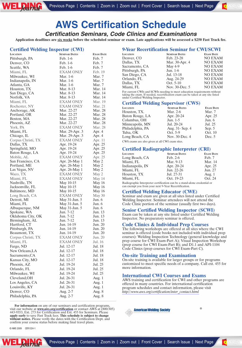
Certified Welding Inspector (CWI)LOCATION SEMINAR DATES EXAM DATE
Pittsburgh, PA Feb. 1-6 Feb. 7Denver, CO Feb. 1-6 Feb. 7Seattle, WA Feb. 1-6 Feb. 7Miami, FL EXAM ONLY Feb. 19Milwaukee, WI Mar. 1-6 Mar. 7Indianapolis, IN Mar. 1-6 Mar. 7Atlanta, GA Mar. 1-6 Mar. 7Houston, TX Mar. 8-13 Mar. 14San Diego, CA Mar. 8-13 Mar. 14Norfolk, VA Mar. 8-13 Mar. 14Miami, FL EXAM ONLY Mar. 19Rochester, NY EXAM ONLY Mar. 21Anchorage, AK Mar. 22-27 Mar. 28Portland, OR Mar. 22-27 Mar. 28Boston, MA Mar. 22-27 Mar. 28Phoenix, AZ Mar. 22-27 Mar. 28York, PA EXAM ONLY Mar. 28Miami, FL Mar. 29-Apr. 3 Apr. 4Chicago, IL Mar. 29-Apr. 3 Apr. 4Corpus Christi, TX EXAM ONLY Apr. 11Dallas, TX Apr. 19-24 Apr. 25Springfield, MO Apr. 19-24 Apr. 25Baton Rouge, LA Apr. 19-24 Apr. 25Mobile, AL EXAM ONLY Apr. 25San Francisco, CA Apr. 26-May 1 May 2Portland, ME Apr. 26-May 1 May 2Las Vegas, NV Apr. 26-May 1 May 2Waco, TX EXAM ONLY May 2Miami, FL EXAM ONLY May 14Nashville, TN May 10-15 May 16Jacksonville, FL May 10-15 May 16Baltimore, MD May 10-15 May 16Long Beach, CA EXAM ONLY May 30Detroit, MI May 31-Jun. 5 Jun. 6Miami, FL May 31-Jun. 5 Jun. 6Albuquerque, NM May 31-Jun. 5 Jun. 6Spokane, WA Jun. 7-12 Jun. 13Oklahoma City, OK Jun. 7-12 Jun. 13Birmingham, AL Jun. 7-12 Jun. 13Hartford, CT Jun. 14-19 Jun. 20Pittsburgh, PA Jun. 14-19 Jun. 20Beaumont, TX Jun. 14-19 Jun. 20Corpus Christi, TX EXAM ONLY Jun. 20Miami, FL EXAM ONLY Jul. 16Fargo, ND Jul. 12-17 Jul. 18New Orleans,LA Jul. 12-17 Jul. 18Sacramento,CA Jul. 12-17 Jul. 18Kansas City, MO Jul. 12-17 Jul. 18Phoenix, AZ Jul. 19-24 Jul. 25Orlando, FL Jul. 19-24 Jul. 25Milwaukee, WI Jul. 19-24 Jul. 25Cleveland,OH Jul. 26-31 Aug. 1Los Angeles, CA Jul. 26-31 Aug. 1Louisville, KY Jul. 26-31 Aug. 1Denver, CO Aug. 2-7 Aug. 8Philadelphia, PA Aug. 2-7 Aug. 8
9-Year Recertification Seminar for CWI/SCWILOCATION SEMINAR DATES EXAM DATE
Denver, CO Feb. 23-28 NO EXAMDallas, TX Mar. 30-Apr. 4 NO EXAMSacramento, CA May 4-9 NO EXAMPittsburgh, PA Jun. 1-6 NO EXAMSan Diego, CA Jul. 13-18 NO EXAMOrlando, FL Aug. 24-29 NO EXAMDallas, TX Oct. 5-10 NO EXAMMiami, FL Nov. 30-Dec. 5 NO EXAMFor current CWIs and SCWIs needing to meet education requirements without taking the exam. If needed, recertification exam can be taken at any site listed under Certified Welding Inspector.
Certified Welding Supervisor (CWS)LOCATION SEMINAR DATES EXAM DATE
Houston, TX. Mar. 2-6 Mar. 7Baton Rouge, LA Apr. 20-24 Apr. 25Columbus, OH Jun. 1-5 Jun. 6Minneapolis, MN Jul. 20-24 Jul. 25Philadelphia, PA Aug. 31- Sep. 4 Sep. 5Tulsa, OK Oct. 5-9 Oct. 10Long Beach, CA Nov. 30-Dec. 4 Dec. 5CWS exams are also given at all CWI exam sites.
Certified Radiographic Interpreter (CRI)LOCATION SEMINAR DATES EXAM DATE
Long Beach, CA Feb. 2-6 Feb. 7Miami, FL Mar. 9-13 Mar. 14Indianapolis, IN Apr. 20-24 Apr. 25Miami, FL Jun. 22-26 Jun. 27Houston, TX Jul. 27-31 Aug. 1Miami, FL Oct. 19-23 Oct. 24Radiographic Interpreter certification can be a stand-alone credential or can exempt you from your next 9-Year Recertification.
Certified Welding Educator (CWE)Seminar and exam are given at all sites listed under CertifiedWelding Inspector. Seminar attendees will not attend the Code Clinic portion of the seminar (usually first two days).
Senior Certified Welding Inspector (SCWI)Exam can be taken at any site listed under Certified WeldingInspector. No preparatory seminar is offered.
Code Clinics & Individual Prep CoursesThe following workshops are offered at all sites where the CWIseminar is offered (code books not included with individual prepcourses): Welding Inspection Technology (general knowledge andprep course for CWI Exam-Part A); Visual Inspection Workshop(prep course for CWI Exam-Part B); and D1.1 and API-1104 Code Clinics (prep courses for CWI Exam-Part C).
On-site Training and ExaminationOn-site training is available for larger groups or for programscustomized to meet specific needs of a company. Call ext. 455 formore information.
International CWI Courses and Exams AWS training and certification for CWI and other programs areoffered in many countries. For international certificationprogram schedules and contact information, please visithttp//:www.aws.org/certification/inter_contact.html
For information on any of our seminars and certification programs,visit our website at www.aws.org/certification or contact AWS at (800/305)443-9353, Ext. 273 for Certification and Ext. 455 for Seminars. Pleaseapply early to save Fast Track fees. This schedule is subject to changewithout notice. Please verify the dates with the Certification Dept. andconfirm your course status before making final travel plans.
AWS Certification ScheduleCertification Seminars, Code Clinics and Examinations
Application deadlines are six weeks before the scheduled seminar or exam. Late applications will be assessed a $250 Fast Track fee.
© AWS 2009 CER1324-1
®
| | | | | |Previous Page Contents Zoom in Zoom out Front Cover Search Issue Next PageLWE DINGJournalJournal BA
M SaGEF
| | | | | |Previous Page Contents Zoom in Zoom out Front Cover Search Issue Next PageLWE DINGJournalJournal BA
M SaGEF
_______________________________
______________
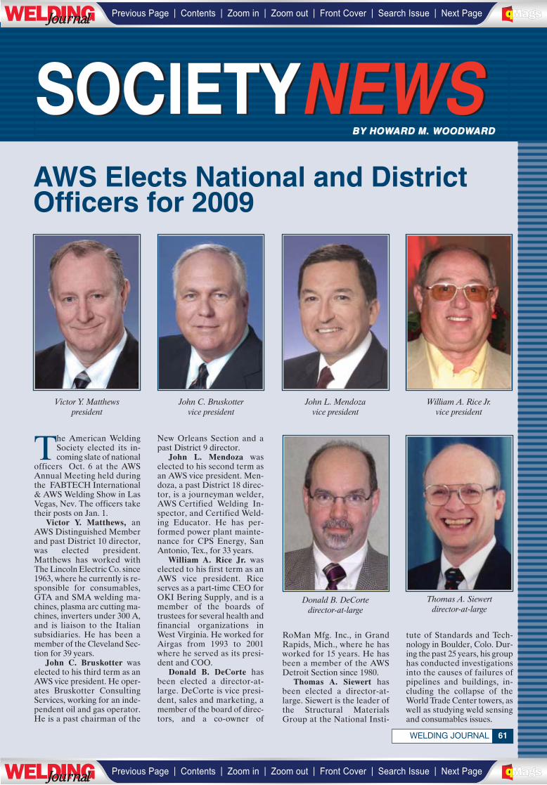
SOCIETYNEWSSOCIETYNEWSBY HOWARD M. WOODWARDBY HOWARD M. WOODWARD
61WELDING JOURNAL
The American WeldingSociety elected its in-coming slate of national
officers Oct. 6 at the AWSAnnual Meeting held duringthe FABTECH International& AWS Welding Show in LasVegas, Nev. The officers taketheir posts on Jan. 1.
Victor Y. Matthews, anAWS Distinguished Memberand past District 10 director,was elected president.Matthews has worked withThe Lincoln Electric Co. since1963, where he currently is re-sponsible for consumables,GTA and SMA welding ma-chines, plasma arc cutting ma-chines, inverters under 300 A,and is liaison to the Italiansubsidiaries. He has been amember of the Cleveland Sec-tion for 39 years.
John C. Bruskotter waselected to his third term as anAWS vice president. He oper-ates Bruskotter ConsultingServices, working for an inde-pendent oil and gas operator.He is a past chairman of the
New Orleans Section and apast District 9 director.
John L. Mendoza waselected to his second term asan AWS vice president. Men-doza, a past District 18 direc-tor, is a journeyman welder,AWS Certified Welding In-spector, and Certified Weld-ing Educator. He has per-formed power plant mainte-nance for CPS Energy, SanAntonio, Tex., for 33 years.
William A. Rice Jr. waselected to his first term as anAWS vice president. Riceserves as a part-time CEO forOKI Bering Supply, and is amember of the boards oftrustees for several health andfinancial organizations inWest Virginia. He worked forAirgas from 1993 to 2001where he served as its presi-dent and COO.
Donald B. DeCorte hasbeen elected a director-at-large. DeCorte is vice presi-dent, sales and marketing, amember of the board of direc-tors, and a co-owner of
Victor Y. Matthewspresident
John C. Bruskottervice president
John L. Mendozavice president
William A. Rice Jr.vice president
Donald B. DeCortedirector-at-large
Thomas A. Siewertdirector-at-large
RoMan Mfg. Inc., in GrandRapids, Mich., where he hasworked for 15 years. He hasbeen a member of the AWSDetroit Section since 1980.
Thomas A. Siewert hasbeen elected a director-at-large. Siewert is the leader ofthe Structural MaterialsGroup at the National Insti-
tute of Standards and Tech-nology in Boulder, Colo. Dur-ing the past 25 years, his grouphas conducted investigationsinto the causes of failures ofpipelines and buildings, in-cluding the collapse of theWorld Trade Center towers, aswell as studying weld sensingand consumables issues.
AWS Elects National and DistrictOfficers for 2009
| | | | | |Previous Page Contents Zoom in Zoom out Front Cover Search Issue Next PageLWE DINGJournalJournal BA
M SaGEF
| | | | | |Previous Page Contents Zoom in Zoom out Front Cover Search Issue Next PageLWE DINGJournalJournal BA
M SaGEF
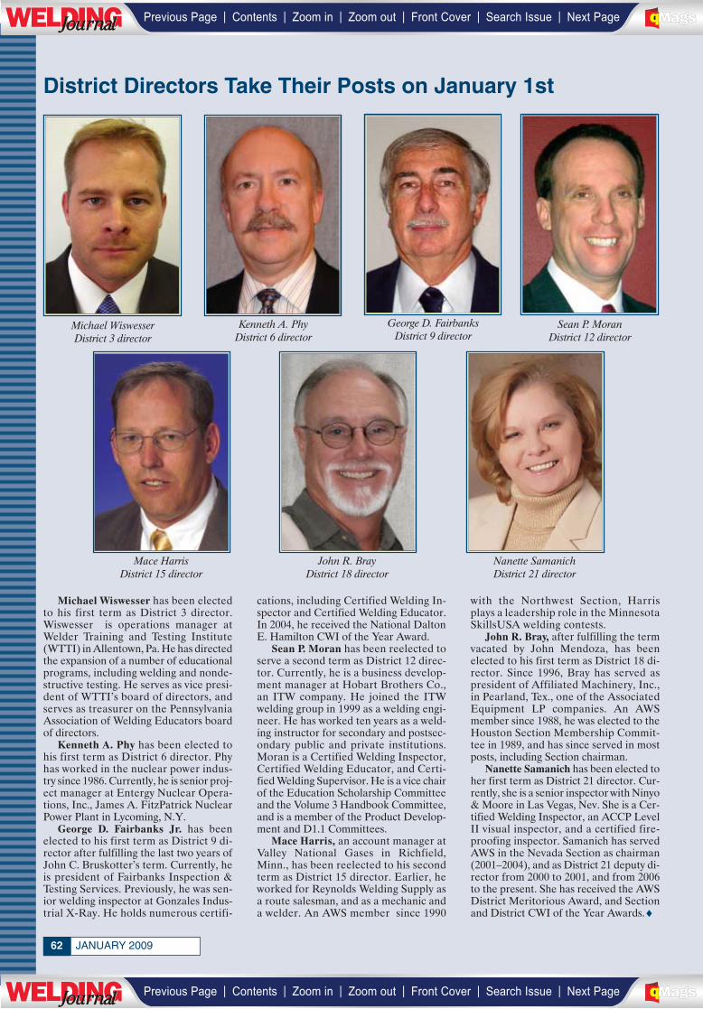
JANUARY 200962
Michael Wiswesser has been electedto his first term as District 3 director.Wiswesser is operations manager atWelder Training and Testing Institute(WTTI) in Allentown, Pa. He has directedthe expansion of a number of educationalprograms, including welding and nonde-structive testing. He serves as vice presi-dent of WTTI’s board of directors, andserves as treasurer on the PennsylvaniaAssociation of Welding Educators boardof directors.
Kenneth A. Phy has been elected tohis first term as District 6 director. Phyhas worked in the nuclear power indus-try since 1986. Currently, he is senior proj-ect manager at Entergy Nuclear Opera-tions, Inc., James A. FitzPatrick NuclearPower Plant in Lycoming, N.Y.
George D. Fairbanks Jr. has beenelected to his first term as District 9 di-rector after fulfilling the last two years ofJohn C. Bruskotter’s term. Currently, heis president of Fairbanks Inspection &Testing Services. Previously, he was sen-ior welding inspector at Gonzales Indus-trial X-Ray. He holds numerous certifi-
cations, including Certified Welding In-spector and Certified Welding Educator.In 2004, he received the National DaltonE. Hamilton CWI of the Year Award.
Sean P. Moran has been reelected toserve a second term as District 12 direc-tor. Currently, he is a business develop-ment manager at Hobart Brothers Co.,an ITW company. He joined the ITWwelding group in 1999 as a welding engi-neer. He has worked ten years as a weld-ing instructor for secondary and postsec-ondary public and private institutions.Moran is a Certified Welding Inspector,Certified Welding Educator, and Certi-fied Welding Supervisor. He is a vice chairof the Education Scholarship Committeeand the Volume 3 Handbook Committee,and is a member of the Product Develop-ment and D1.1 Committees.
Mace Harris, an account manager atValley National Gases in Richfield,Minn., has been reelected to his secondterm as District 15 director. Earlier, heworked for Reynolds Welding Supply asa route salesman, and as a mechanic anda welder. An AWS member since 1990
with the Northwest Section, Harrisplays a leadership role in the MinnesotaSkillsUSA welding contests.
John R. Bray, after fulfilling the termvacated by John Mendoza, has beenelected to his first term as District 18 di-rector. Since 1996, Bray has served aspresident of Affiliated Machinery, Inc.,in Pearland, Tex., one of the AssociatedEquipment LP companies. An AWSmember since 1988, he was elected to theHouston Section Membership Commit-tee in 1989, and has since served in mostposts, including Section chairman.
Nanette Samanich has been elected toher first term as District 21 director. Cur-rently, she is a senior inspector with Ninyo& Moore in Las Vegas, Nev. She is a Cer-tified Welding Inspector, an ACCP LevelII visual inspector, and a certified fire-proofing inspector. Samanich has servedAWS in the Nevada Section as chairman(2001–2004), and as District 21 deputy di-rector from 2000 to 2001, and from 2006to the present. She has received the AWSDistrict Meritorious Award, and Sectionand District CWI of the Year Awards.♦
District Directors Take Their Posts on January 1st
Nanette SamanichDistrict 21 director
John R. BrayDistrict 18 director
Mace HarrisDistrict 15 director
George D. FairbanksDistrict 9 director
Sean P. MoranDistrict 12 director
Kenneth A. PhyDistrict 6 director
Michael WiswesserDistrict 3 director
| | | | | |Previous Page Contents Zoom in Zoom out Front Cover Search Issue Next PageLWE DINGJournalJournal BA
M SaGEF
| | | | | |Previous Page Contents Zoom in Zoom out Front Cover Search Issue Next PageLWE DINGJournalJournal BA
M SaGEF
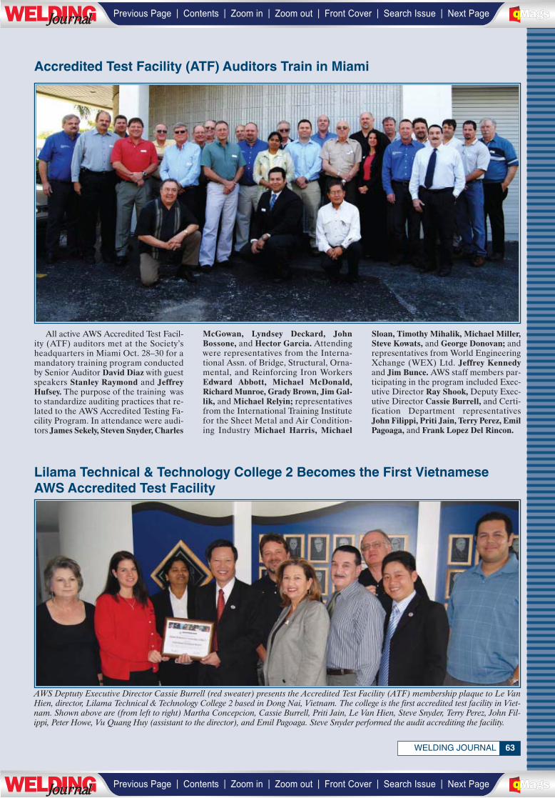
63WELDING JOURNAL
All active AWS Accredited Test Facil-ity (ATF) auditors met at the Society’sheadquarters in Miami Oct. 28–30 for amandatory training program conductedby Senior Auditor David Diaz with guestspeakers Stanley Raymond and JeffreyHufsey. The purpose of the training wasto standardize auditing practices that re-lated to the AWS Accredited Testing Fa-cility Program. In attendance were audi-tors James Sekely, Steven Snyder, Charles
McGowan, Lyndsey Deckard, JohnBossone, and Hector Garcia. Attendingwere representatives from the Interna-tional Assn. of Bridge, Structural, Orna-mental, and Reinforcing Iron WorkersEdward Abbott, Michael McDonald,Richard Munroe, Grady Brown, Jim Gal-lik, and Michael Relyin; representativesfrom the International Training Institutefor the Sheet Metal and Air Condition-ing Industry Michael Harris, Michael
Sloan, Timothy Mihalik, Michael Miller,Steve Kowats, and George Donovan; andrepresentatives from World EngineeringXchange (WEX) Ltd. Jeffrey Kennedyand Jim Bunce. AWS staff members par-ticipating in the program included Exec-utive Director Ray Shook, Deputy Exec-utive Director Cassie Burrell, and Certi-fication Department representativesJohn Filippi, Priti Jain, Terry Perez, EmilPagoaga, and Frank Lopez Del Rincon.
Accredited Test Facility (ATF) Auditors Train in Miami
AWS Deptuty Executive Director Cassie Burrell (red sweater) presents the Accredited Test Facility (ATF) membership plaque to Le VanHien, director, Lilama Technical & Technology College 2 based in Dong Nai, Vietnam. The college is the first accredited test facility in Viet-nam. Shown above are (from left to right) Martha Concepcion, Cassie Burrell, Priti Jain, Le Van Hien, Steve Snyder, Terry Perez, John Fil-ippi, Peter Howe, Vu Quang Huy (assistant to the director), and Emil Pagoaga. Steve Snyder performed the audit accrediting the facility.
Lilama Technical & Technology College 2 Becomes the First Vietnamese AWS Accredited Test Facility
| | | | | |Previous Page Contents Zoom in Zoom out Front Cover Search Issue Next PageLWE DINGJournalJournal BA
M SaGEF
| | | | | |Previous Page Contents Zoom in Zoom out Front Cover Search Issue Next PageLWE DINGJournalJournal BA
M SaGEF
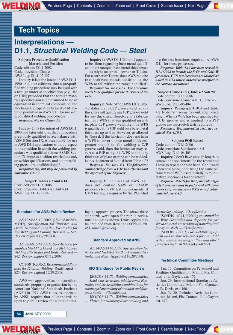
JANUARY 200964
Tech Topics
Standards for ANSI Public Review
A5.12M/A5.12:200X (ISO 6848:2004MOD), Specification for Tungsten andOxide Dispersed Tungsten Electrodes forArc Welding and Cutting. Revised — $25.Review expired 12/29/2008.
A5.22/A5.22M:200X, Specification forStainless Steel Flux Cored and Metal CoredWelding Electrodes and Rods. Revised —$42. Review expires 01/12/2009.
C6.1-89 (R200X), Recommended Prac-tices for Friction Welding. Reaffirmed —$25. Review expired 12/29/2008.
AWS was approved as an accreditedstandards-preparing organization by theAmerican National Standards Institute(ANSI) in 1979. AWS rules, as approvedby ANSI, require that all standards beopen to public review for comment dur-
ing the approval process. The above threestandards were open for public reviewuntil the dates shown. Draft copies maybe obtained from Rosalinda O’Neill, ext.451, [email protected].
Standard Approved by ANSI
A5.14/A5.14M:2009, Specification forNickel and Nickel-Alloy Bare Welding Elec-trodes and Rods. Approved 10/28/2008.
ISO Standards for Public Review
ISO/DIS 14171, Welding consumables— Solid wire electrodes, tubular cored elec-trodes and electrode/flux combinations forsubmerged arc welding of nonalloy and fine-grain steels — Classification
ISO/DIS 14174, Welding consumables— Fluxes for submerged arc welding and
electroslag welding – Classification ISO/DIS 14341, Welding consumables
— Wire electrodes and deposits for gasshielded metal arc welding of nonalloy andfine-grain steels — Classification
ISO/DIS 7291.2, Gas welding equip-ment — Pressure regulators for manifoldsystem used in welding, cutting and alliedprocesses up to 30 000 kpA (300 bar)
Technical Committee Meetings
Jan. 15, Committee on Personnel andFacilities Qualification. Miami, Fla. Con-tact: J. L. Gayler, ext. 472.
Jan. 29, International Standards Ac-tivities Committee. Miami, Fla. Contact:A. R. Davis, ext. 466.
Jan. 29, 30, Technical Activities Com-mittee. Miami, Fla. Contact: J. L. Gayler,ext. 472.
Subject: Procedure Qualification — Material and Position
Code edition: D1.1:2002Code provision: Clause 4AWS Log: D1.1-02-I07
Inquiry 1: Is it the intent of AWS D1.1,1990 and later editions, that a prequali-fied welding procedure may be used witha foreign material specification (e.g., JISor DIN) provided that the foreign mate-rial specification is determined to be ofequivalent in chemical composition andmechanical properties to an ASTM ma-terial permitted in AWS D1.1 for use withprequalified welding procedures?
Response: No, see Clause 3.3.
Inquiry 2: Is the intent of AWS D1.1,1990 and later editions, that a procedurepreviously qualified in accordance withASME Section IX, is acceptable for usein AWS D1.1 applications without respectto the position in which the welding pro-cedure was qualified (since ASME Sec-tion IX imposes position restrictions onlyon welder qualifications, and not on weld-ing procedure qualifications)?
Response: No, but may be permitted bySubclause 4.1.1.2.
Subject: Tables 4.2 and 4.14Code edition: D1.1:2006Code provision: Tables 4.2 and 4.14AWS Log: D1.1-06-I02
Inquiry 1: AWS D1.1 Table 4.2 appearsto be silent regarding base metal qualifi-cation on unequal base metal thicknesses— as might occur in a corner or T-joint.For a corner or T-joint, does AWS requirethat both base metals qualified on theWPS to fall within the range qualified?
Response: No, see 4.9.1.1. The procedureneeds to be qualified for the thickness of theweld.
Inquiry 2: Note “d” of AWS D1.1 Table4.2 states that a CJP groove weld on anythickness will qualify any PJP groove weldfor any thickness. Therefore, if a fabrica-tor has a WPS that was qualified on a 1⁄8-in. plate CJP groove weld, then the WPSis qualified for a CJP weld on a base metalthickness up to 1⁄4 in. However, as allowedby Note d, if the fabricator does not havea WPS to cover a base metal thicknessgreater than 1⁄4 in. for welding a CJPgroove weld, then the fabricator may re-vert to a PJP using this WPS so that anythickness of plate or pipe can be welded.Is this the intent of Note d from Table 4.2?
Response: No, see 1.4.1. The fabricatorcannot change from a CJP to a PJP withoutthe approval of the Engineer.
Inquiry 3: Table 4.14 of AWS D1.1does not contain SAW or GMAWprocesses for CVN test requirements. IfCVN testing is required by the PO, what
are the test locations required by AWSD1.1 for these processes?
Response: Table 4.14 has been revised inD1.1:2008 to include the SAW and GMAWprocesses. CVN test locations are located asnoted in 4.34 unless otherwise specified inthe contract documents.
Subject: Clause 4.10.3, Table 4.2 Note “d”Code edition: D1.1:2006Code provision: Clause 4.10.3, Table 4.2AWS Log: D1.1-06-I04
Inquiry: Paragraph 4.10.3 and Table4.2 Note “d” seem to contradict eachother. When a WPS has been qualified fora CJP groove and is applied to a PJPgroove are macroetch tests required?
Response: Yes, macroetch tests are re-quired. See 4.10.3.
Subject: PQR RetestCode edition: D1.1:2006Code provision: Subclause 4.8.5AWS Log: D1.1-06-I05
Inquiry: I don’t have enough length toremove the specimens for the retest andI have to repeat the side bend. Can I welda new test piece, done using the same pa-rameters of WPS used initially to manu-facture specimens for the retest?
Response: Retests for that particular typeof test specimen may be performed with spec-imens cut from the same WPS qualificationmaterial, see 4.8.5.
Interpretations —D1.1, Structural Welding Code — Steel
__________
| | | | | |Previous Page Contents Zoom in Zoom out Front Cover Search Issue Next PageLWE DINGJournalJournal BA
M SaGEF
| | | | | |Previous Page Contents Zoom in Zoom out Front Cover Search Issue Next PageLWE DINGJournalJournal BA
M SaGEF
65WELDING JOURNAL
Affiliate Companies4Front Engineered Solutions
1612 Hutton Dr. #140Carrolton, TX 75006
Advanced Entertainment Tech 735 Los Angeles Ave. Monrovia, CA 91016
BuhlerPrince670 Windcrest Dr.Holland, MI 49423
Cambridge Materials Testing1177 Franklin Blvd., Unit 2
Cambridge, ON N1R 7W4, Canada
Contratistas Civiles & MecanicosAv 27 de Febrero 1760 Alameda
Santo Domingo 10902Dominican Republic
Cro Magnon Corp. 1509 East Tower Phil
Stock Exchange CenterExchange Rd., Ortigas Center
Pasig City 1700, Philippines
Downey Metal Products 907 Oothcalooga St.Calhoun, GA 37001
Falat Pejvak Co.Unit 12, No. 2, 4th St. Gandi St.
Tehran 1517739516, Iran
G2 Metal Fab224 Rickenbacker Cir.Livermore, CA 94551
Gainey Machine & Fab. LLC961 Patrick Hwy.
Hartsville, SC 29550
Imperial Fabricating Co.160 Kirby Dr.
Portland, TN 37148
Industrial Global Supply SA de CVBenito Juarez N. No. 109Queretaro 76000, Mexico
ITA IndustrialEstrada Do Gramado 290
Embu São Paulo 06833902, Brazil
J Julian & Asociados SAEPS #A-611, 8260 NW 14th St.
Doral, FL 33126
MGS Inc.178 Muddy Creek Church Rd.
Denver, PA 17517
Mantenimiento & Construcciones SA Alcaldediaz 6th St. #602
Panama El Dorado, Panama
Red Head Oil and Gas Services Co.Dammam King Saud Bin Abdulaziz St.
Najd Bldg., Dammam 31433 PO Box 10907, Dammam Eastern
Province, Saudi Arabia
Ribolt Fabrication LLC13814 KY 57
Tollesboro, KY 41189
Smith Metal WorksPO Box 852
Phenix City, AL 36870
Tri-Angle Welding Supply520 Crane St., Unit A
Lake Elsinore, CA 92530
Supporting Companies Caltrop Corp.
2200 Powell St., Ste. 1125Emeryville, CA 94608
Icesa Welding SystemsAve. San Vicente 7,
San Miguel XochimangaAtizapan Estado de Mexico 52927
Mexico
ITER dba MISPO Box 363453
San Juan, PR 00936
The Rose Corp.401 N. 8th St.
Reading, PA 19601
Powell-Delta/Unibus Div.515 Railroad Ave.
Northlake, IL 60164
Stegner Controls3333 Bald Mountain Rd.Auburn Hills, MI 48326
Educational InstitutionsAshland County/
West Homes Career Center1783 S.R. 60
Ashland, OH 44805
Earle C. Clements Job Corps Academy2302 U.S. Hwy. 60 E.
Morganfield, KY 42437
Panola College678 Roughrider
Center, TX 75935
Pirad International Inspection Co.Eram St. Alley #2, Faramod Bldg.
First Fl., Unit #1Shiraz, Fars 71438-37416, Iran
Plumber’s L. U. No. 1, Training Center37-11 47th Ave.
Long Island City, NY 11101
PVD Technical Training and Certification Joint Stock Co.
Dong Xuyen Ind. Zone, 30/4 Rd.Rach Dua Ward, Vung Tau City, SR
Vietnam
Southwestern Oregon C. C.1988 Newmark Ave.Coos Bay, OR 97420
Sury Engineering Technology Temple Gate,Thalasserry
Kannur, Keral G70102, India
Taft Union High School701 7th St.
Taft, CA 93268
New AWS Supporters
Membership Counts
Member As of Grades 12/01/08Sustaining..........................................508Supporting.........................................309Educational.......................................484Affiliate..............................................467Welding distributor............................49Total corporate members..................1,817Individual members.....................49,419Student + transitional members........5,315Total members..............................54,734
Sustaining CompanyGeneron IGS, Inc.
16250 Tomball Pkwy.Houston, TX 77086
(713) 937-5200
Sustaining Representative:Rex M. Hardy
Generon IGS is a division of In-novative Gas Systems (IGS), aglobal technology company thatspecializes in systems that produceindustrial nitrogen, oxygen, andprocess gas separations. IGS alsohas operating facilities in Germany,Italy, Russia, China, Thailand, andthe Middle East region.
| | | | | |Previous Page Contents Zoom in Zoom out Front Cover Search Issue Next PageLWE DINGJournalJournal BA
M SaGEF
| | | | | |Previous Page Contents Zoom in Zoom out Front Cover Search Issue Next PageLWE DINGJournalJournal BA
M SaGEF
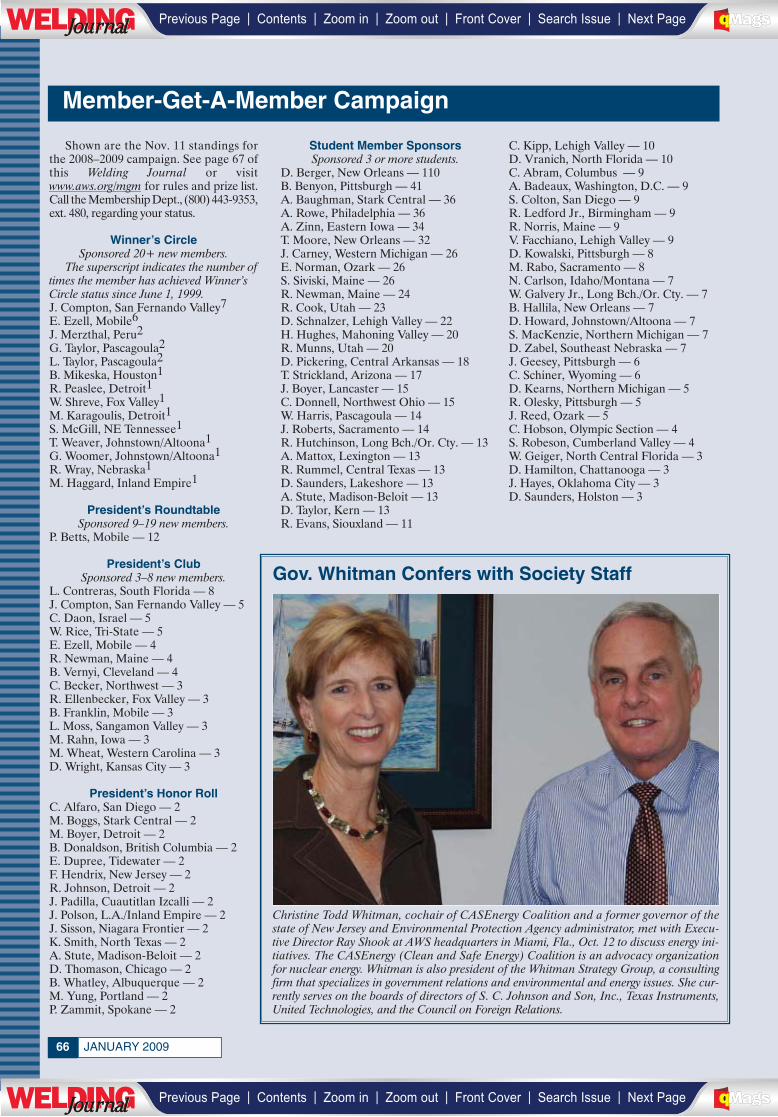
JANUARY 200966
Shown are the Nov. 11 standings forthe 2008–2009 campaign. See page 67 ofthis Welding Journal or visitwww.aws.org/mgm for rules and prize list.Call the Membership Dept., (800) 443-9353,ext. 480, regarding your status.
Winner’s CircleSponsored 20+ new members.
The superscript indicates the number oftimes the member has achieved Winner’sCircle status since June 1, 1999.J. Compton, San Fernando Valley7E. Ezell, Mobile6J. Merzthal, Peru2G. Taylor, Pascagoula2L. Taylor, Pascagoula2B. Mikeska, Houston1R. Peaslee, Detroit1W. Shreve, Fox Valley1M. Karagoulis, Detroit1S. McGill, NE Tennessee1T. Weaver, Johnstown/Altoona1G. Woomer, Johnstown/Altoona1R. Wray, Nebraska1M. Haggard, Inland Empire1
President’s RoundtableSponsored 9–19 new members.
P. Betts, Mobile — 12
President’s ClubSponsored 3–8 new members.
L. Contreras, South Florida — 8J. Compton, San Fernando Valley — 5C. Daon, Israel — 5W. Rice, Tri-State — 5E. Ezell, Mobile — 4R. Newman, Maine — 4B. Vernyi, Cleveland — 4C. Becker, Northwest — 3R. Ellenbecker, Fox Valley — 3B. Franklin, Mobile — 3L. Moss, Sangamon Valley — 3M. Rahn, Iowa — 3M. Wheat, Western Carolina — 3D. Wright, Kansas City — 3
President’s Honor RollC. Alfaro, San Diego — 2M. Boggs, Stark Central — 2M. Boyer, Detroit — 2B. Donaldson, British Columbia — 2E. Dupree, Tidewater — 2F. Hendrix, New Jersey — 2R. Johnson, Detroit — 2J. Padilla, Cuautitlan Izcalli — 2J. Polson, L.A./Inland Empire — 2J. Sisson, Niagara Frontier — 2K. Smith, North Texas — 2A. Stute, Madison-Beloit — 2D. Thomason, Chicago — 2B. Whatley, Albuquerque — 2M. Yung, Portland — 2P. Zammit, Spokane — 2
Student Member SponsorsSponsored 3 or more students.
D. Berger, New Orleans — 110B. Benyon, Pittsburgh — 41A. Baughman, Stark Central — 36A. Rowe, Philadelphia — 36A. Zinn, Eastern Iowa — 34T. Moore, New Orleans — 32J. Carney, Western Michigan — 26E. Norman, Ozark — 26S. Siviski, Maine — 26R. Newman, Maine — 24R. Cook, Utah — 23D. Schnalzer, Lehigh Valley — 22H. Hughes, Mahoning Valley — 20R. Munns, Utah — 20D. Pickering, Central Arkansas — 18T. Strickland, Arizona — 17J. Boyer, Lancaster — 15C. Donnell, Northwest Ohio — 15W. Harris, Pascagoula — 14J. Roberts, Sacramento — 14R. Hutchinson, Long Bch./Or. Cty. — 13A. Mattox, Lexington — 13R. Rummel, Central Texas — 13D. Saunders, Lakeshore — 13A. Stute, Madison-Beloit — 13D. Taylor, Kern — 13R. Evans, Siouxland — 11
C. Kipp, Lehigh Valley — 10D. Vranich, North Florida — 10C. Abram, Columbus — 9A. Badeaux, Washington, D.C. — 9S. Colton, San Diego — 9R. Ledford Jr., Birmingham — 9R. Norris, Maine — 9V. Facchiano, Lehigh Valley — 9D. Kowalski, Pittsburgh — 8M. Rabo, Sacramento — 8N. Carlson, Idaho/Montana — 7W. Galvery Jr., Long Bch./Or. Cty. — 7B. Hallila, New Orleans — 7D. Howard, Johnstown/Altoona — 7S. MacKenzie, Northern Michigan — 7D. Zabel, Southeast Nebraska — 7J. Geesey, Pittsburgh — 6C. Schiner, Wyoming — 6D. Kearns, Northern Michigan — 5R. Olesky, Pittsburgh — 5J. Reed, Ozark — 5C. Hobson, Olympic Section — 4S. Robeson, Cumberland Valley — 4W. Geiger, North Central Florida — 3D. Hamilton, Chattanooga — 3J. Hayes, Oklahoma City — 3D. Saunders, Holston — 3
Member-Get-A-Member Campaign
Gov. Whitman Confers with Society Staff
Christine Todd Whitman, cochair of CASEnergy Coalition and a former governor of thestate of New Jersey and Environmental Protection Agency administrator, met with Execu-tive Director Ray Shook at AWS headquarters in Miami, Fla., Oct. 12 to discuss energy ini-tiatives. The CASEnergy (Clean and Safe Energy) Coalition is an advocacy organizationfor nuclear energy. Whitman is also president of the Whitman Strategy Group, a consultingfirm that specializes in government relations and environmental and energy issues. She cur-rently serves on the boards of directors of S. C. Johnson and Son, Inc., Texas Instruments,United Technologies, and the Council on Foreign Relations.
| | | | | |Previous Page Contents Zoom in Zoom out Front Cover Search Issue Next PageLWE DINGJournalJournal BA
M SaGEF
| | | | | |Previous Page Contents Zoom in Zoom out Front Cover Search Issue Next PageLWE DINGJournalJournal BA
M SaGEF
___________
| | | | | |Previous Page Contents Zoom in Zoom out Front Cover Search Issue Next PageLWE DINGJournalJournal BA
M SaGEF
| | | | | |Previous Page Contents Zoom in Zoom out Front Cover Search Issue Next PageLWE DINGJournalJournal BA
M SaGEF
____________________
_________
Mr. Ms. Mrs. Dr. Please print • Duplicate this page as needed
Last Name______________________________________________________________________________
First Name___________________________________________________________M.I.________________
Title_________________________________________________Birthdate __________________________
Were you ever an AWS Member? YES NO If “YES,” give year_____and Member # ____________
Primary Phone ( )____________________ Secondary Phone ( ) ____________________
FAX ( )______________________________ E-Mail ______________________________________
Did you learn of the Society through an AWS Member? Yes No
If “yes,” Member’s name:_________________________________ Member’s # (if known): ______________
From time to time, AWS sends out informational emails about programs we offer, new Member benefits, savings opportunities andchanges to our website. If you would prefer not to receive these emails, please check here
Type of Business (Check ONE only)A Contract constructionB Chemicals & allied productsC Petroleum & coal industriesD Primary metal industriesE Fabricated metal productsF Machinery except elect. (incl. gas welding)G Electrical equip., supplies, electrodesH Transportation equip. — air, aerospaceI Transportation equip. — automotiveJ Transportation equip. — boats, shipsK Transportation equip. — railroadL UtilitiesM Welding distributors & retail tradeN Misc. repair services (incl. welding shops)O Educational Services (univ., libraries, schools)P Engineering & architectural services (incl.
assns.)Q Misc. business services (incl. commercial labs)R Government (federal, state, local)S OtherJob Classification (Check ONE only)01 President, owner, partner, officer02 Manager, director, superintendent (or
assistant)03 Sales04 Purchasing05 Engineer — welding20 Engineer — design21 Engineer — manufacturing06 Engineer — other10 Architect designer12 Metallurgist13 Research & development22 Quality control07 Inspector, tester08 Supervisor, foreman14 Technician09 Welder, welding or cutting operator11 Consultant15 Educator17 Librarian16 Student18 Customer Service19 OtherTechnical Interests (Check all that apply)A Ferrous metalsB AluminumC Nonferrous metals except aluminumD Advanced materials/IntermetallicsE CeramicsF High energy beam processesG Arc weldingH Brazing and solderingI Resistance weldingJ Thermal sprayK CuttingL NDTM Safety and healthN Bending and shearingO Roll formingP Stamping and punchingQ AerospaceR AutomotiveS MachineryT MarineU Piping and tubingV Pressure vessels and tanksW Sheet metalX StructuresY OtherZ Automation1 Robotics2 Computerization of Welding
AWS MEMBERSHIP APPLICATION BOOK/CD-ROM SELECTION(Pay Only $25... up to a $192 value)
A free local Section Membership isincluded with all AWS Memberships
Section Affiliation Preference (if known):
NOTE: Only New Individual Members are eligible for thisselection. Be sure to add $25 to your total payment.ONLY ONE SELECTION PLEASE.
New Member Renewal
NOTE: Dues include $18.70 for Welding Journalsubscription and $4.00 for the AWS Foundation.
PAYMENT INFORMATION (Required)
AWS STUDENT MEMBERSHIP †††Domestic (Canada & Mexico incl.)..................................$15International ......................................................................$50
TOTAL PAYMENT..............................................................$________
Application Date:
Payment can be made (in U.S. dollars) by check or money order (international or foreign), payable to the American Welding Society, or by charge card.Check Money Order Bill Me
American Express Diners Club Carte Blanche MasterCard Visa Discover Other
Your Account Number Expiration Date (mm/yy)
Signature of Applicant:Office Use Only Check # Account #
Source Code WJ Date Amount†Two-year Individual Membership Special Offer: applies only to new AWS Individual Members. ††DiscountPublication Offer: applies only to new AWS Individual Members. Select one of the four listed publications for an additional$25; International Members add $75 ($25 for book selection and $50 for international shipping); Multi-Year Discount:First year is $80, each additional year is $75. No limit on years (not available to Student Members). †††Student Member:Any individual who attends a recognized college, university, technical, vocational school or high school is eligible. DomesticMembers are those students residing in Norh America (incl. Canada & Mexico). This membership includes the WeldingJournal magazine. Student Memberships do not include a discounted publication. Airmail Postage Option: InternationalMembers may receive their magazines via Airmail by adding $99 to the annual dues amount.
Company (if applicable) __________________________________________________________________
Address ______________________________________________________________________________
Address Con’t. __________________________________________________________________________
City__________________State/Province________Zip/Postal Code _____________Country ____________
Who pays your dues?: Company Self-paid Sex: Male FemaleEducation level: High school diploma Associate’s Bachelor’s Master’s Doctoral
NOTE: This address will be used for all Society mail.
4 Easy Ways to Join or Renew:Mail this form, along with your payment, to AWS
Call the Membership Department at (800) 443-9353, ext. 480Fax this completed form to (305) 443-5647
Join or renew on our website <www.aws.org/membership>
NOTE: This data will be used to develop programs and services toserve you better.
PROFILE DATA
ADDRESS
$4.00 of membership dues goes to support the AWSFoundation.
SPECIAL OFFER FOR NEW AWS INDIVIDUAL MEMBERS – TWO YEARS FOR $135 (a $25 savings)
$135
P.O. Box 440367Miami, FL 33144-0367Telephone (800) 443-9353FAX (305) 443-5647Visit our website: www.aws.org
Member Services Revised 5/4/06
Jefferson’s WeldingEncyclopedia (CD-ROM only)Design and Planning Manual forCost-Effective WeldingWelding MetallurgyWelding Handbook (9th Ed., Vol. 2)
(Optional)
PLUS... Get a popular welding publication for only $25 ($192 value)
SAVE $25(New Members Only)
(Optional){
ONE-YEAR AWS INDIVIDUAL MEMBERSHIP ................................$80TWO-YEAR AWS INDIVIDUAL MEMBERSHIP† ............................$160New Member? ___Yes ___No
If yes, add one-time initiation fee of $12 ..................................................................................$__________
Domestic Members add $25 for book selection ($192 value), and save up to 87%††............ $__ ___ __International Members add $75 for book selection (note: $50 is for international shipping) ††..$__ ___ __(Note: Book Selection applies to new Individual Members only – Book selections on upper-right corner)
TOTAL PAYMENT .....................................................................................................$___________
| | | | | |Previous Page Contents Zoom in Zoom out Front Cover Search Issue Next PageLWE DINGJournalJournal BA
M SaGEF
| | | | | |Previous Page Contents Zoom in Zoom out Front Cover Search Issue Next PageLWE DINGJournalJournal BA
M SaGEF
__________________
______
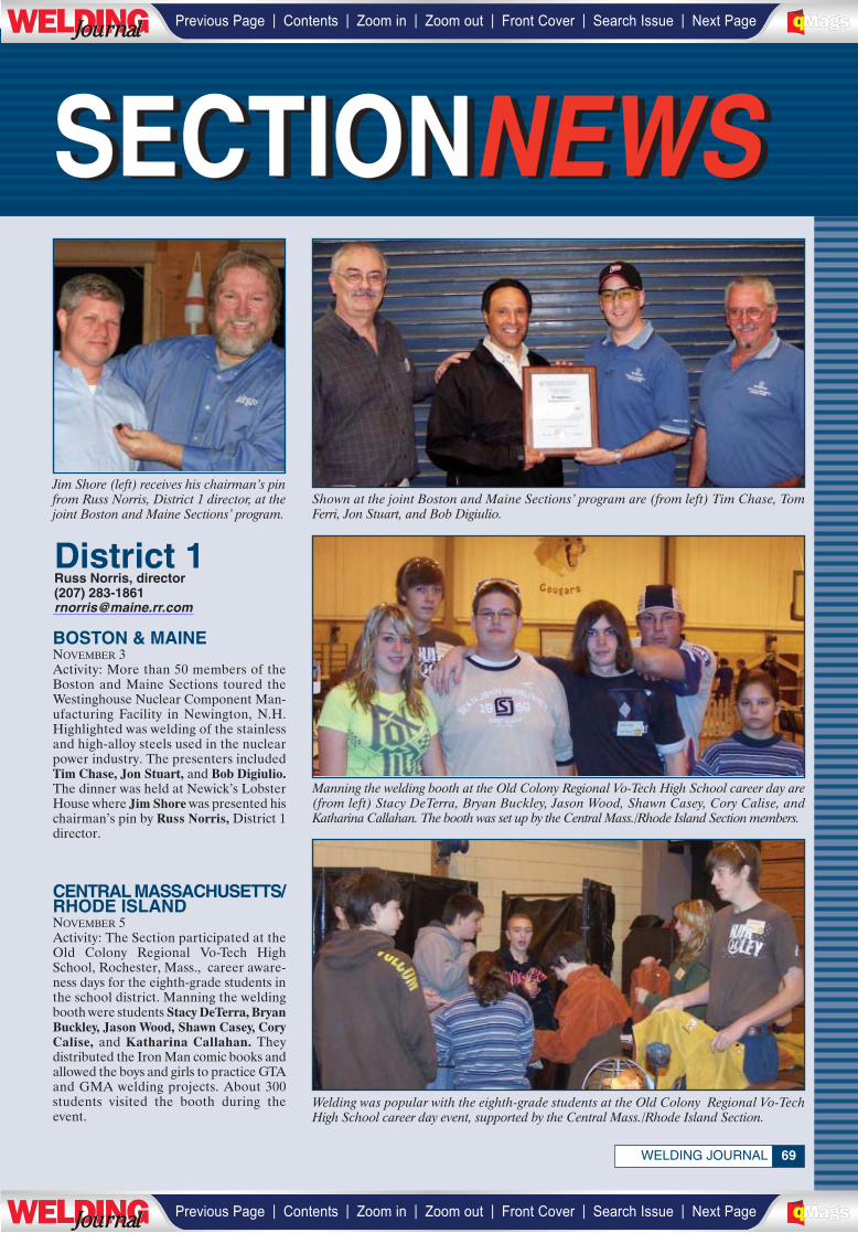
SECTIONNEWSSECTIONNEWS
69
District 1Russ Norris, director(207) [email protected]
WELDING JOURNAL
Shown at the joint Boston and Maine Sections’ program are (from left) Tim Chase, TomFerri, Jon Stuart, and Bob Digiulio.
Jim Shore (left) receives his chairman’s pinfrom Russ Norris, District 1 director, at thejoint Boston and Maine Sections’ program.
BOSTON & MAINENOVEMBER 3Activity: More than 50 members of theBoston and Maine Sections toured theWestinghouse Nuclear Component Man-ufacturing Facility in Newington, N.H.Highlighted was welding of the stainlessand high-alloy steels used in the nuclearpower industry. The presenters includedTim Chase, Jon Stuart, and Bob Digiulio.The dinner was held at Newick’s LobsterHouse where Jim Shore was presented hischairman’s pin by Russ Norris, District 1director.
CENTRAL MASSACHUSETTS/RHODE ISLANDNOVEMBER 5Activity: The Section participated at theOld Colony Regional Vo-Tech HighSchool, Rochester, Mass., career aware-ness days for the eighth-grade students inthe school district. Manning the weldingbooth were students Stacy DeTerra, BryanBuckley, Jason Wood, Shawn Casey, CoryCalise, and Katharina Callahan. Theydistributed the Iron Man comic books andallowed the boys and girls to practice GTAand GMA welding projects. About 300students visited the booth during theevent.
Manning the welding booth at the Old Colony Regional Vo-Tech High School career day are(from left) Stacy DeTerra, Bryan Buckley, Jason Wood, Shawn Casey, Cory Calise, andKatharina Callahan. The booth was set up by the Central Mass./Rhode Island Section members.
Welding was popular with the eighth-grade students at the Old Colony Regional Vo-TechHigh School career day event, supported by the Central Mass./Rhode Island Section.
________________
| | | | | |Previous Page Contents Zoom in Zoom out Front Cover Search Issue Next PageLWE DINGJournalJournal BA
M SaGEF
| | | | | |Previous Page Contents Zoom in Zoom out Front Cover Search Issue Next PageLWE DINGJournalJournal BA
M SaGEF

JANUARY 200970
District 2Kenneth R. Stockton, director(908) [email protected]
CONNECTICUTOCTOBER 28Activity: The Section held a businessmeeting at Jacoby’s Restaurant in Meri-den, Conn. Chairman Gary Shubert dis-cussed a Section scholarship program,Walt Chojnacki outlined the Section’s fi-nances, and Bob Cullen reported on theSection’s educational program activities.Nino Olivares presented ideas for toursthe members could take, and District 1Director Russ Norris presented Districtand national news items.
GREEN & WHITE MTS.NOVEMBER 13Speaker: Russ Norris, District 1 directorTopic: Oxyfuel gas safetyActivity: The presentation included a teston oxyfuel safety dos and don’ts, followedby a video presentation on the subjectfrom Victor-Thermadyne. The programincluded a lively discussion on various gassafety topics.
MAINENOVEMBER 20Activity: The Section held a businessmeeting at Metso Paper Co. in Biddeford,Maine. Attending to business were Chair-man Scott Lee, Mike Gendron, Ray Roy,and Russ Norris, District 1 director.
Taking care of Connecticut Section business are (seated, from left) Walt Chojnacki, ChairGary Shubert, and John Matthews; (standing, from left) District 1 Director Russ Norris,Bob Cullen, and Nino Olivares.
Shown at the Maine Section business meeting are (seated) Ray Roy, and (standing, fromleft) Chair Scott Lee, Mike Gendron, and Russ Norris, District 1 director.
Shown at the Green & White Mountains Section event are (front, from left) Richard Fuller, Chair Ray Hendersen II, Perley Lund, JenniferEastly, and Ernie Plumb; (back, from left) Joe Torkarski, Gilbert LeClair, Phil Witteman, Gary Buckley, John Steel, and Geoff Putnam.
LONG ISLANDNOVEMBER 13Activity: The Section members touredUnderwriters Laboratories, Inc., inMelville, N.Y., to study its safety testingfacilities for household appliances, indus-trial controls, wire and cable, and security
_____________________
| | | | | |Previous Page Contents Zoom in Zoom out Front Cover Search Issue Next PageLWE DINGJournalJournal BA
M SaGEF
| | | | | |Previous Page Contents Zoom in Zoom out Front Cover Search Issue Next PageLWE DINGJournalJournal BA
M SaGEF
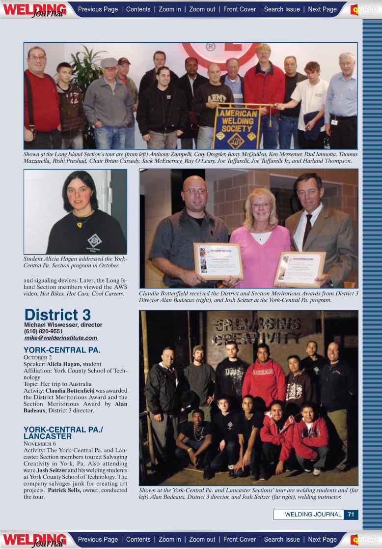
71WELDING JOURNAL
District 3Michael Wiswesser, director(610) [email protected]
and signaling devices. Later, the Long Is-land Section members viewed the AWSvideo, Hot Bikes, Hot Cars, Cool Careers.
YORK-CENTRAL PA.OCTOBER 2Speaker: Alicia Hagan, studentAffiliation: York County School of Tech-nologyTopic: Her trip to AustraliaActivity: Claudia Bottenfield was awardedthe District Meritorious Award and theSection Meritorious Award by AlanBadeaux, District 3 director.
YORK-CENTRAL PA./LANCASTERNOVEMBER 6Activity: The York-Central Pa. and Lan-caster Section members toured SalvagingCreativity in York, Pa. Also attendingwere Josh Seitzer and his welding studentsat York County School of Technology. Thecompany salvages junk for creating artprojects. Patrick Sells, owner, conductedthe tour.
Shown at the Long Island Section’s tour are (from left) Anthony Zampelli, Cory Drogsler, Barry McQuillen, Ken Messemer, Paul Iannotta, ThomasMazzarella, Rishi Prashad, Chair Brian Cassady, Jack McEnerney, Ray O’Leary, Joe Tuffarelli, Joe Tuffarelli Jr., and Harland Thompson.
Claudia Bottenfield received the District and Section Meritorious Awards from District 3Director Alan Badeaux (right), and Josh Seitzer at the York-Central Pa. program.
Student Alicia Hagan addressed the York-Central Pa. Section program in October.
Shown at the York-Central Pa. and Lancaster Sections’ tour are welding students and (farleft) Alan Badeaux, District 3 director, and Josh Seitzer (far right), welding instructor.
___________________
| | | | | |Previous Page Contents Zoom in Zoom out Front Cover Search Issue Next PageLWE DINGJournalJournal BA
M SaGEF
| | | | | |Previous Page Contents Zoom in Zoom out Front Cover Search Issue Next PageLWE DINGJournalJournal BA
M SaGEF
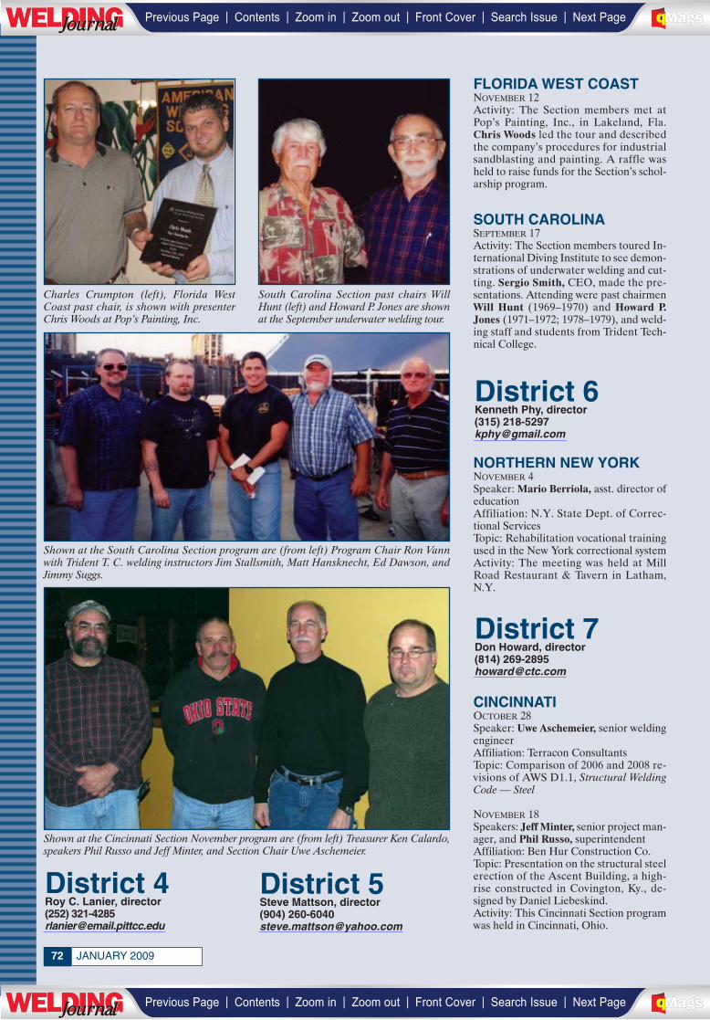
JANUARY 200972
District 7Don Howard, director(814) [email protected]
District 6Kenneth Phy, director(315) [email protected]
District 5Steve Mattson, director(904) [email protected]
District 4Roy C. Lanier, director(252) [email protected]
Charles Crumpton (left), Florida WestCoast past chair, is shown with presenterChris Woods at Pop’s Painting, Inc.
South Carolina Section past chairs WillHunt (left) and Howard P. Jones are shownat the September underwater welding tour.
Shown at the South Carolina Section program are (from left) Program Chair Ron Vannwith Trident T. C. welding instructors Jim Stallsmith, Matt Hansknecht, Ed Dawson, andJimmy Suggs.
Shown at the Cincinnati Section November program are (from left) Treasurer Ken Calardo,speakers Phil Russo and Jeff Minter, and Section Chair Uwe Aschemeier.
FLORIDA WEST COASTNOVEMBER 12Activity: The Section members met atPop’s Painting, Inc., in Lakeland, Fla.Chris Woods led the tour and describedthe company’s procedures for industrialsandblasting and painting. A raffle washeld to raise funds for the Section’s schol-arship program.
SOUTH CAROLINASEPTEMBER 17Activity: The Section members toured In-ternational Diving Institute to see demon-strations of underwater welding and cut-ting. Sergio Smith, CEO, made the pre-sentations. Attending were past chairmenWill Hunt (1969–1970) and Howard P.Jones (1971–1972; 1978–1979), and weld-ing staff and students from Trident Tech-nical College.
NORTHERN NEW YORKNOVEMBER 4Speaker: Mario Berriola, asst. director ofeducationAffiliation: N.Y. State Dept. of Correc-tional ServicesTopic: Rehabilitation vocational trainingused in the New York correctional systemActivity: The meeting was held at MillRoad Restaurant & Tavern in Latham,N.Y.
CINCINNATIOCTOBER 28Speaker: Uwe Aschemeier, senior weldingengineerAffiliation: Terracon ConsultantsTopic: Comparison of 2006 and 2008 re-visions of AWS D1.1, Structural WeldingCode — Steel
NOVEMBER 18Speakers: Jeff Minter, senior project man-ager, and Phil Russo, superintendentAffiliation: Ben Hur Construction Co.Topic: Presentation on the structural steelerection of the Ascent Building, a high-rise constructed in Covington, Ky., de-signed by Daniel Liebeskind.Activity: This Cincinnati Section programwas held in Cincinnati, Ohio.
____________
____________
_____________________________________
| | | | | |Previous Page Contents Zoom in Zoom out Front Cover Search Issue Next PageLWE DINGJournalJournal BA
M SaGEF
| | | | | |Previous Page Contents Zoom in Zoom out Front Cover Search Issue Next PageLWE DINGJournalJournal BA
M SaGEF
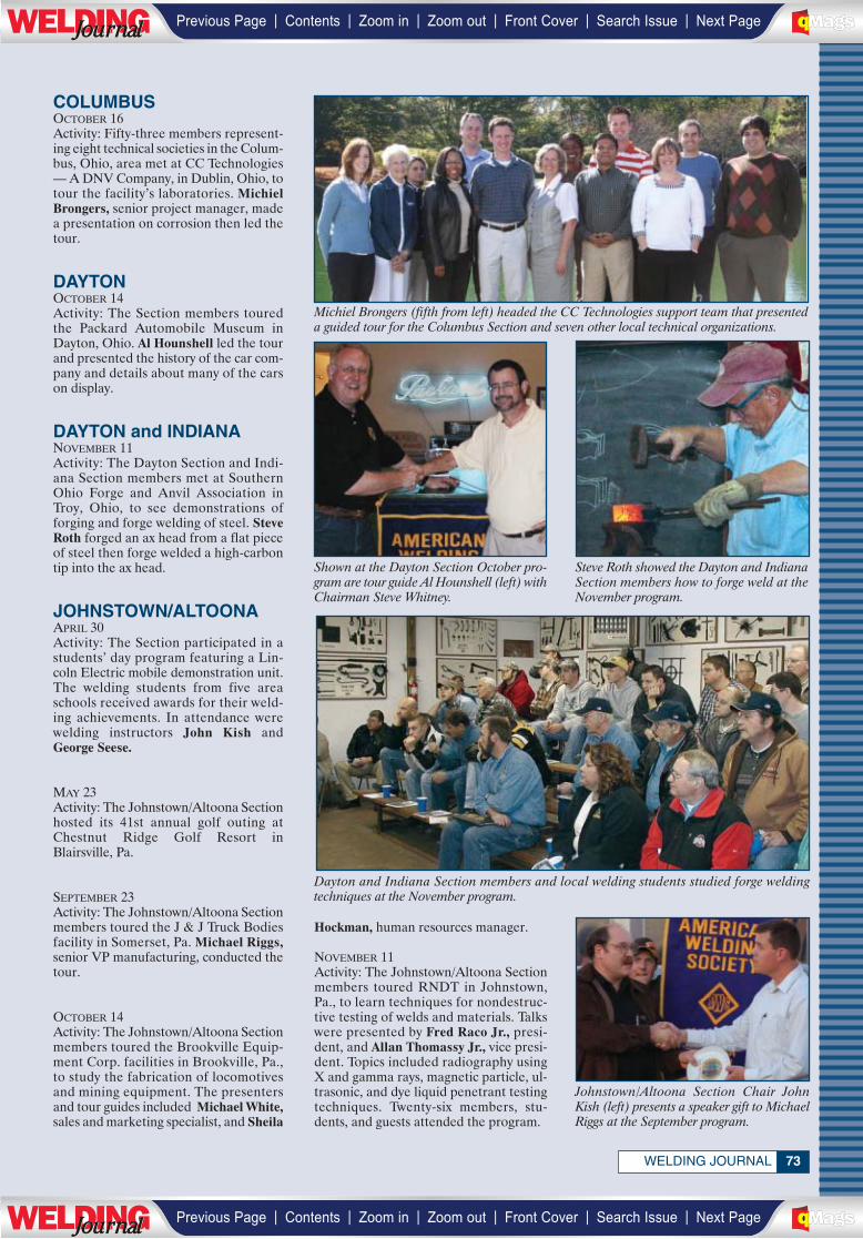
73WELDING JOURNAL
Michiel Brongers (fifth from left) headed the CC Technologies support team that presenteda guided tour for the Columbus Section and seven other local technical organizations.
Dayton and Indiana Section members and local welding students studied forge weldingtechniques at the November program.
Shown at the Dayton Section October pro-gram are tour guide Al Hounshell (left) withChairman Steve Whitney.
Steve Roth showed the Dayton and IndianaSection members how to forge weld at theNovember program.
COLUMBUSOCTOBER 16Activity: Fifty-three members represent-ing eight technical societies in the Colum-bus, Ohio, area met at CC Technologies— A DNV Company, in Dublin, Ohio, totour the facility’s laboratories. MichielBrongers, senior project manager, madea presentation on corrosion then led thetour.
DAYTONOCTOBER 14Activity: The Section members touredthe Packard Automobile Museum inDayton, Ohio. Al Hounshell led the tourand presented the history of the car com-pany and details about many of the carson display.
DAYTON and INDIANANOVEMBER 11Activity: The Dayton Section and Indi-ana Section members met at SouthernOhio Forge and Anvil Association inTroy, Ohio, to see demonstrations offorging and forge welding of steel. SteveRoth forged an ax head from a flat pieceof steel then forge welded a high-carbontip into the ax head.
JOHNSTOWN/ALTOONAAPRIL 30Activity: The Section participated in astudents’ day program featuring a Lin-coln Electric mobile demonstration unit.The welding students from five areaschools received awards for their weld-ing achievements. In attendance werewelding instructors John Kish andGeorge Seese.
MAY 23Activity: The Johnstown/Altoona Sectionhosted its 41st annual golf outing atChestnut Ridge Golf Resort inBlairsville, Pa.
SEPTEMBER 23Activity: The Johnstown/Altoona Sectionmembers toured the J & J Truck Bodiesfacility in Somerset, Pa. Michael Riggs,senior VP manufacturing, conducted thetour.
OCTOBER 14Activity: The Johnstown/Altoona Sectionmembers toured the Brookville Equip-ment Corp. facilities in Brookville, Pa.,to study the fabrication of locomotivesand mining equipment. The presentersand tour guides included Michael White,sales and marketing specialist, and Sheila
Hockman, human resources manager.
NOVEMBER 11Activity: The Johnstown/Altoona Sectionmembers toured RNDT in Johnstown,Pa., to learn techniques for nondestruc-tive testing of welds and materials. Talkswere presented by Fred Raco Jr., presi-dent, and Allan Thomassy Jr., vice presi-dent. Topics included radiography usingX and gamma rays, magnetic particle, ul-trasonic, and dye liquid penetrant testingtechniques. Twenty-six members, stu-dents, and guests attended the program.
Johnstown/Altoona Section Chair JohnKish (left) presents a speaker gift to MichaelRiggs at the September program.
| | | | | |Previous Page Contents Zoom in Zoom out Front Cover Search Issue Next PageLWE DINGJournalJournal BA
M SaGEF
| | | | | |Previous Page Contents Zoom in Zoom out Front Cover Search Issue Next PageLWE DINGJournalJournal BA
M SaGEF
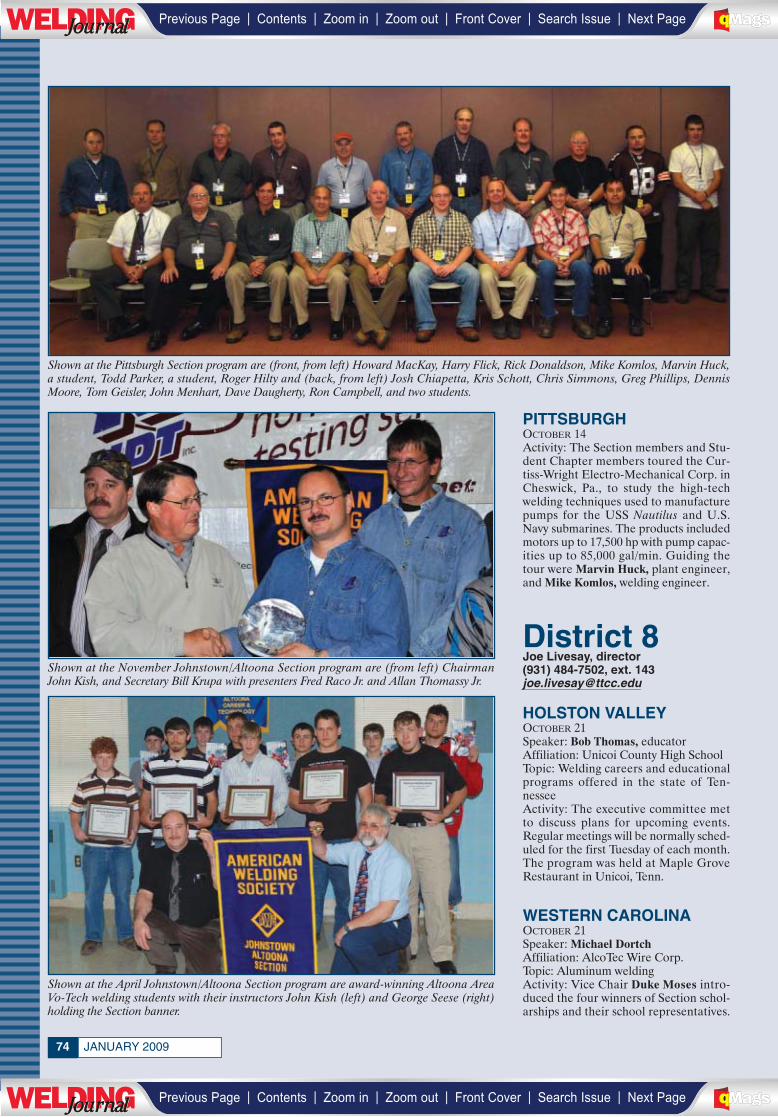
JANUARY 200974
Shown at the November Johnstown/Altoona Section program are (from left) ChairmanJohn Kish, and Secretary Bill Krupa with presenters Fred Raco Jr. and Allan Thomassy Jr.
Shown at the April Johnstown/Altoona Section program are award-winning Altoona AreaVo-Tech welding students with their instructors John Kish (left) and George Seese (right)holding the Section banner.
Shown at the Pittsburgh Section program are (front, from left) Howard MacKay, Harry Flick, Rick Donaldson, Mike Komlos, Marvin Huck,a student, Todd Parker, a student, Roger Hilty and (back, from left) Josh Chiapetta, Kris Schott, Chris Simmons, Greg Phillips, DennisMoore, Tom Geisler, John Menhart, Dave Daugherty, Ron Campbell, and two students.
PITTSBURGHOCTOBER 14Activity: The Section members and Stu-dent Chapter members toured the Cur-tiss-Wright Electro-Mechanical Corp. inCheswick, Pa., to study the high-techwelding techniques used to manufacturepumps for the USS Nautilus and U.S.Navy submarines. The products includedmotors up to 17,500 hp with pump capac-ities up to 85,000 gal/min. Guiding thetour were Marvin Huck, plant engineer,and Mike Komlos, welding engineer.
HOLSTON VALLEYOCTOBER 21Speaker: Bob Thomas, educatorAffiliation: Unicoi County High SchoolTopic: Welding careers and educationalprograms offered in the state of Ten-nesseeActivity: The executive committee metto discuss plans for upcoming events.Regular meetings will be normally sched-uled for the first Tuesday of each month.The program was held at Maple GroveRestaurant in Unicoi, Tenn.
WESTERN CAROLINAOCTOBER 21Speaker: Michael DortchAffiliation: AlcoTec Wire Corp.Topic: Aluminum weldingActivity: Vice Chair Duke Moses intro-duced the four winners of Section schol-arships and their school representatives.
District 8Joe Livesay, director(931) 484-7502, ext. [email protected]_______________
| | | | | |Previous Page Contents Zoom in Zoom out Front Cover Search Issue Next PageLWE DINGJournalJournal BA
M SaGEF
| | | | | |Previous Page Contents Zoom in Zoom out Front Cover Search Issue Next PageLWE DINGJournalJournal BA
M SaGEF
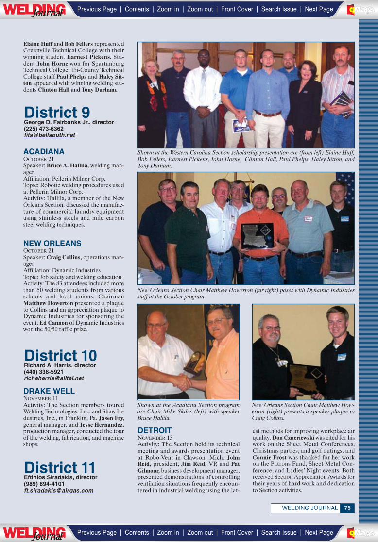
75WELDING JOURNAL
District 11Eftihios Siradakis, director(989) [email protected]
District 9George D. Fairbanks Jr., director(225) [email protected]
District 10Richard A. Harris, director(440) [email protected]
Elaine Huff and Bob Fellers representedGreenville Technical College with theirwinning student Earnest Pickens. Stu-dent John Horne won for SpartanburgTechnical College. Tri-County TechnicalCollege staff Paul Phelps and Haley Sit-ton appeared with winning welding stu-dents Clinton Hall and Tony Durham.
ACADIANAOCTOBER 21Speaker: Bruce A. Hallila, welding man-agerAffiliation: Pellerin Milnor Corp.Topic: Robotic welding procedures usedat Pellerin Milnor Corp.Activity: Hallila, a member of the NewOrleans Section, discussed the manufac-ture of commercial laundry equipmentusing stainless steels and mild carbonsteel welding techniques.
NEW ORLEANSOCTOBER 21Speaker: Craig Collins, operations man-agerAffiliation: Dynamic IndustriesTopic: Job safety and welding educationActivity: The 83 attendees included morethan 50 welding students from variousschools and local unions. ChairmanMatthew Howerton presented a plaqueto Collins and an appreciation plaque toDynamic Industries for sponsoring theevent. Ed Cannon of Dynamic Industrieswon the 50/50 raffle prize.
Shown at the Western Carolina Section scholarship presentation are (from left) Elaine Huff,Bob Fellers, Earnest Pickens, John Horne, Clinton Hall, Paul Phelps, Haley Sitton, andTony Durham.
New Orleans Section Chair Matthew Howerton (far right) poses with Dynamic Industriesstaff at the October program.
Shown at the Acadiana Section programare Chair Mike Skiles (left) with speakerBruce Hallila.
New Orleans Section Chair Matthew How-erton (right) presents a speaker plaque toCraig Collins.
DRAKE WELLNOVEMBER 11Activity: The Section members touredWelding Technologies, Inc., and Shaw In-dustries, Inc., in Franklin, Pa. Jasen Fry,general manager, and Jesse Hernandez,production manager, conducted the tourof the welding, fabrication, and machineshops.
DETROITNOVEMBER 13Activity: The Section held its technicalmeeting and awards presentation eventat Robo-Vent in Clawson, Mich. JohnReid, president, Jim Reid, VP, and PatGilmour, business development manager,presented demonstrations of controllingventilation situations frequently encoun-tered in industrial welding using the lat-
est methods for improving workplace airquality. Don Czneriewski was cited for hiswork on the Sheet Metal Conferences,Christmas parties, and golf outings, andConnie Frost was thanked for her workon the Patrons Fund, Sheet Metal Con-ference, and Ladies’ Night events. Bothreceived Section Appreciation Awards fortheir years of hard work and dedicationto Section activities.__________________
_____________
________________
| | | | | |Previous Page Contents Zoom in Zoom out Front Cover Search Issue Next PageLWE DINGJournalJournal BA
M SaGEF
| | | | | |Previous Page Contents Zoom in Zoom out Front Cover Search Issue Next PageLWE DINGJournalJournal BA
M SaGEF
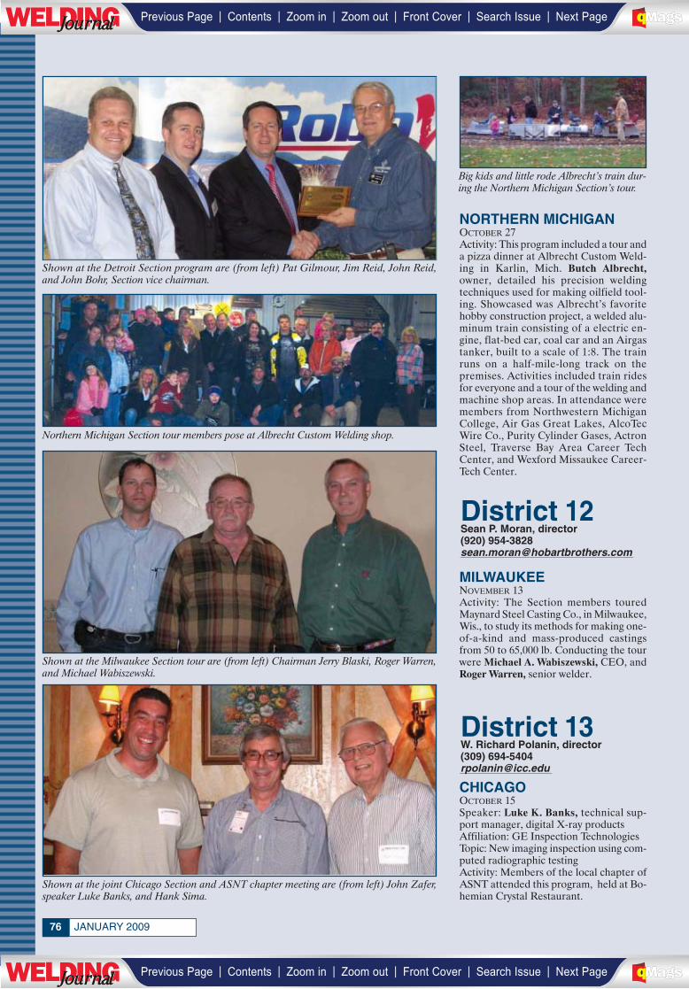
JANUARY 200976
District 12Sean P. Moran, director(920) [email protected]
District 13W. Richard Polanin, director(309) [email protected]
Shown at the Detroit Section program are (from left) Pat Gilmour, Jim Reid, John Reid,and John Bohr, Section vice chairman.
Big kids and little rode Albrecht’s train dur-ing the Northern Michigan Section’s tour.
Northern Michigan Section tour members pose at Albrecht Custom Welding shop.
Shown at the joint Chicago Section and ASNT chapter meeting are (from left) John Zafer,speaker Luke Banks, and Hank Sima.
Shown at the Milwaukee Section tour are (from left) Chairman Jerry Blaski, Roger Warren,and Michael Wabiszewski.
NORTHERN MICHIGANOCTOBER 27Activity: This program included a tour anda pizza dinner at Albrecht Custom Weld-ing in Karlin, Mich. Butch Albrecht,owner, detailed his precision weldingtechniques used for making oilfield tool-ing. Showcased was Albrecht’s favoritehobby construction project, a welded alu-minum train consisting of a electric en-gine, flat-bed car, coal car and an Airgastanker, built to a scale of 1:8. The trainruns on a half-mile-long track on thepremises. Activities included train ridesfor everyone and a tour of the welding andmachine shop areas. In attendance weremembers from Northwestern MichiganCollege, Air Gas Great Lakes, AlcoTecWire Co., Purity Cylinder Gases, ActronSteel, Traverse Bay Area Career TechCenter, and Wexford Missaukee Career-Tech Center.
MILWAUKEENOVEMBER 13Activity: The Section members touredMaynard Steel Casting Co., in Milwaukee,Wis., to study its methods for making one-of-a-kind and mass-produced castingsfrom 50 to 65,000 lb. Conducting the tourwere Michael A. Wabiszewski, CEO, andRoger Warren, senior welder.
CHICAGOOCTOBER 15Speaker: Luke K. Banks, technical sup-port manager, digital X-ray productsAffiliation: GE Inspection TechnologiesTopic: New imaging inspection using com-puted radiographic testingActivity: Members of the local chapter ofASNT attended this program, held at Bo-hemian Crystal Restaurant.
________________________
_____________
| | | | | |Previous Page Contents Zoom in Zoom out Front Cover Search Issue Next PageLWE DINGJournalJournal BA
M SaGEF
| | | | | |Previous Page Contents Zoom in Zoom out Front Cover Search Issue Next PageLWE DINGJournalJournal BA
M SaGEF
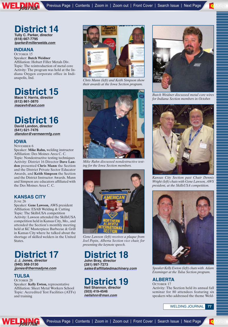
77WELDING JOURNAL
District 17J. J. Jones, director(940) [email protected]
District 16David Landon, director(641) [email protected]
District 14Tully C. Parker, director(618) [email protected]
District 15Mace V. Harris, director(612) [email protected]
District 18John Bray, director(281) [email protected]
District 19Neil Shannon, director(503) [email protected]
Butch Weidner discussed metal core wiresfor Indiana Section members in October.
Mike Rahn discussed nondestructive test-ing for the Iowa Section members.
Kansas City Section past Chair DennisWright (left) chats with Gene Lawson, AWSpresident, at the SkillsUSA competition.
Speaker Kelly Ewton (left) chats with AdamEnsminger at the Tulsa Section program.
Gene Lawson (left) receives a plaque fromJoel Pepin, Alberta Section vice chair, forpresenting the keynote speech.
Chris Mann (left) and Keith Simpson showtheir awards at the Iowa Section program.
INDIANAOCTOBER 15Speaker: Butch WeidnerAffiliation: Hobart Filler Metals Div.Topic: The reintroduction of metal coreActivity: The program was held at the In-diana Oxygen corporate office in Indi-anapolis, Ind.
TULSAOCTOBER 28Speaker: Kelly Ewton, representativeAffiliation: Sheet Metal Workers SchoolTopic: Accredited Test Facilities (ATFs)and training
ALBERTAOCTOBER 17Activity: The Section held its annual fallseminar for 80 attendees featuring sixspeakers who addressed the theme Weld-
IOWANOVEMBER 6Speaker: Mike Rahn, welding instructorAffiliation: Des Moines Area C. C.Topic: Nondestructive testing techniquesActivity: District 16 Director Dave Lan-don presented Chris Mann the Sectionand the District Private Sector EducatorAwards, and Keith Simpson the Sectionand the District Instructor Awards. Mannand Simpson are educators affiliated withthe Des Moines Area C. C.
KANSAS CITYJUNE 26Speaker: Gene Lawson, AWS presidentAffiliation: ESAB Welding & CuttingTopic: The SkillsUSA competitionActivity: Lawson attended the SkillsUSAcompetition held in Kansas City, Mo., andattended the Section’s monthly meetingheld at KC Masterpiece Barbecue & Grillin Kansas City where he talked about theshortage of skilled welders in the UnitedStates.
_____________
___________________
_________________
______________
________________________________________
| | | | | |Previous Page Contents Zoom in Zoom out Front Cover Search Issue Next PageLWE DINGJournalJournal BA
M SaGEF
| | | | | |Previous Page Contents Zoom in Zoom out Front Cover Search Issue Next PageLWE DINGJournalJournal BA
M SaGEF
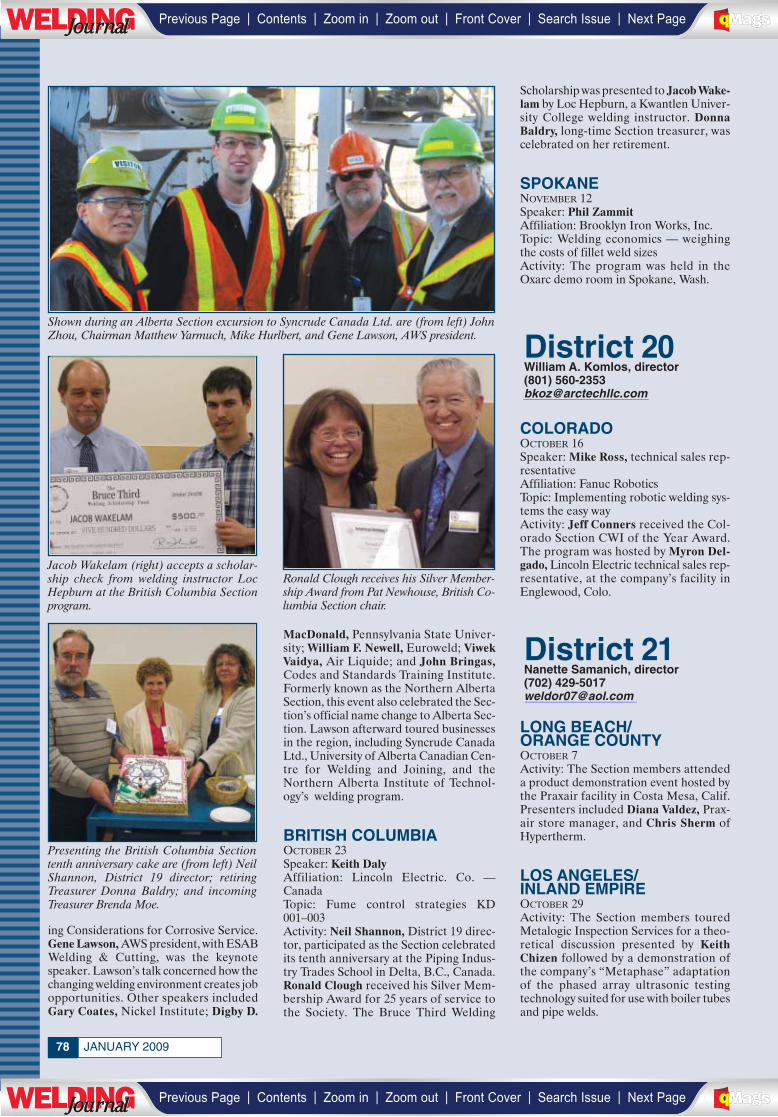
JANUARY 200978
Scholarship was presented to Jacob Wake-lam by Loc Hepburn, a Kwantlen Univer-sity College welding instructor. DonnaBaldry, long-time Section treasurer, wascelebrated on her retirement.
SPOKANENOVEMBER 12Speaker: Phil ZammitAffiliation: Brooklyn Iron Works, Inc.Topic: Welding economics — weighingthe costs of fillet weld sizesActivity: The program was held in theOxarc demo room in Spokane, Wash.
COLORADOOCTOBER 16Speaker: Mike Ross, technical sales rep-resentativeAffiliation: Fanuc RoboticsTopic: Implementing robotic welding sys-tems the easy wayActivity: Jeff Conners received the Col-orado Section CWI of the Year Award.The program was hosted by Myron Del-gado, Lincoln Electric technical sales rep-resentative, at the company’s facility inEnglewood, Colo.
LONG BEACH/ORANGE COUNTYOCTOBER 7Activity: The Section members attendeda product demonstration event hosted bythe Praxair facility in Costa Mesa, Calif.Presenters included Diana Valdez, Prax-air store manager, and Chris Sherm ofHypertherm.
LOS ANGELES/INLAND EMPIREOCTOBER 29Activity: The Section members touredMetalogic Inspection Services for a theo-retical discussion presented by KeithChizen followed by a demonstration ofthe company’s “Metaphase” adaptationof the phased array ultrasonic testingtechnology suited for use with boiler tubesand pipe welds.
ing Considerations for Corrosive Service.Gene Lawson, AWS president, with ESABWelding & Cutting, was the keynotespeaker. Lawson’s talk concerned how thechanging welding environment creates jobopportunities. Other speakers includedGary Coates, Nickel Institute; Digby D.
MacDonald, Pennsylvania State Univer-sity; William F. Newell, Euroweld; ViwekVaidya, Air Liquide; and John Bringas,Codes and Standards Training Institute.Formerly known as the Northern AlbertaSection, this event also celebrated the Sec-tion’s official name change to Alberta Sec-tion. Lawson afterward toured businessesin the region, including Syncrude CanadaLtd., University of Alberta Canadian Cen-tre for Welding and Joining, and theNorthern Alberta Institute of Technol-ogy’s welding program.
BRITISH COLUMBIAOCTOBER 23Speaker: Keith DalyAffiliation: Lincoln Electric. Co. —CanadaTopic: Fume control strategies KD001–003Activity: Neil Shannon, District 19 direc-tor, participated as the Section celebratedits tenth anniversary at the Piping Indus-try Trades School in Delta, B.C., Canada.Ronald Clough received his Silver Mem-bership Award for 25 years of service tothe Society. The Bruce Third Welding
Shown during an Alberta Section excursion to Syncrude Canada Ltd. are (from left) JohnZhou, Chairman Matthew Yarmuch, Mike Hurlbert, and Gene Lawson, AWS president.
Presenting the British Columbia Sectiontenth anniversary cake are (from left) NeilShannon, District 19 director; retiringTreasurer Donna Baldry; and incomingTreasurer Brenda Moe.
Jacob Wakelam (right) accepts a scholar-ship check from welding instructor LocHepburn at the British Columbia Sectionprogram.
Ronald Clough receives his Silver Member-ship Award from Pat Newhouse, British Co-lumbia Section chair.
District 21Nanette Samanich, director(702) [email protected]
District 20William A. Komlos, director(801) [email protected]_______________
______________
| | | | | |Previous Page Contents Zoom in Zoom out Front Cover Search Issue Next PageLWE DINGJournalJournal BA
M SaGEF
| | | | | |Previous Page Contents Zoom in Zoom out Front Cover Search Issue Next PageLWE DINGJournalJournal BA
M SaGEF
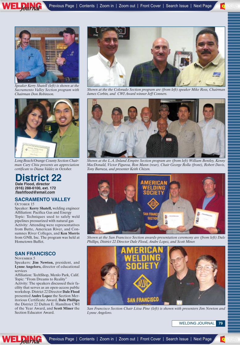
79WELDING JOURNAL
Shown at the the Colorado Section program are (from left) speaker Mike Ross, ChairmanJames Corbin, and CWI Award winner Jeff Conners.
Speaker Kerry Shatell (left) is shown at theSacramento Valley Section program withChairman Don Robinson.
San Francisco Section Chair Liisa Pine (left) is shown with presenters Jim Newton andLynne Angeloro.
Shown at the San Francisco Section awards-presentation ceremony are (from left) DalePhillips, District 22 Director Dale Flood, Andre Lopez, and Scott Miner.
Shown at the L.A./Inland Empire Section program are (from left) William Bentley, KennyMacDonald, Victor Figuroa, Ron Mann (rear), Chair George Rolla (front), Robert Davis,Tony Barraza, and presenter Keith Chizen.
Long Beach/Orange County Section Chair-man Cary Chiu presents an appreciationcertificate to Diana Valdez in October.
SACRAMENTO VALLEYOCTOBER 15Speaker: Kerry Shatell, welding engineerAffiliation: Pacifica Gas and EnergyTopic: Techniques used to safely weldpipelines pressurized with natural gasActivity: Attending were representativesfrom Butte, American River, and Con-sumnes River Colleges, and Ken Morrisfrom GNB, Inc. The program was held atHometown Buffet.
SAN FRANCISCONOVEMBER 5Speakers: Jim Newton, president, andLynne Angeloro, director of educationalservicesAffiliation: TechShop, Menlo Park, Calif.Topic: “From Dreams to Reality”Activity: The speakers discussed their fa-cility that serves as an open-access publicworkshop. District 22 Director Dale Floodpresented Andre Lopez the Section Mer-itorious Certificate Award, Dale Phillipsthe District 22 Dalton E. Hamilton CWIof the Year Award, and Scott Miner theSection Educator Award.
District 22Dale Flood, director(916) 288-6100, ext. [email protected]________________
| | | | | |Previous Page Contents Zoom in Zoom out Front Cover Search Issue Next PageLWE DINGJournalJournal BA
M SaGEF
| | | | | |Previous Page Contents Zoom in Zoom out Front Cover Search Issue Next PageLWE DINGJournalJournal BA
M SaGEF
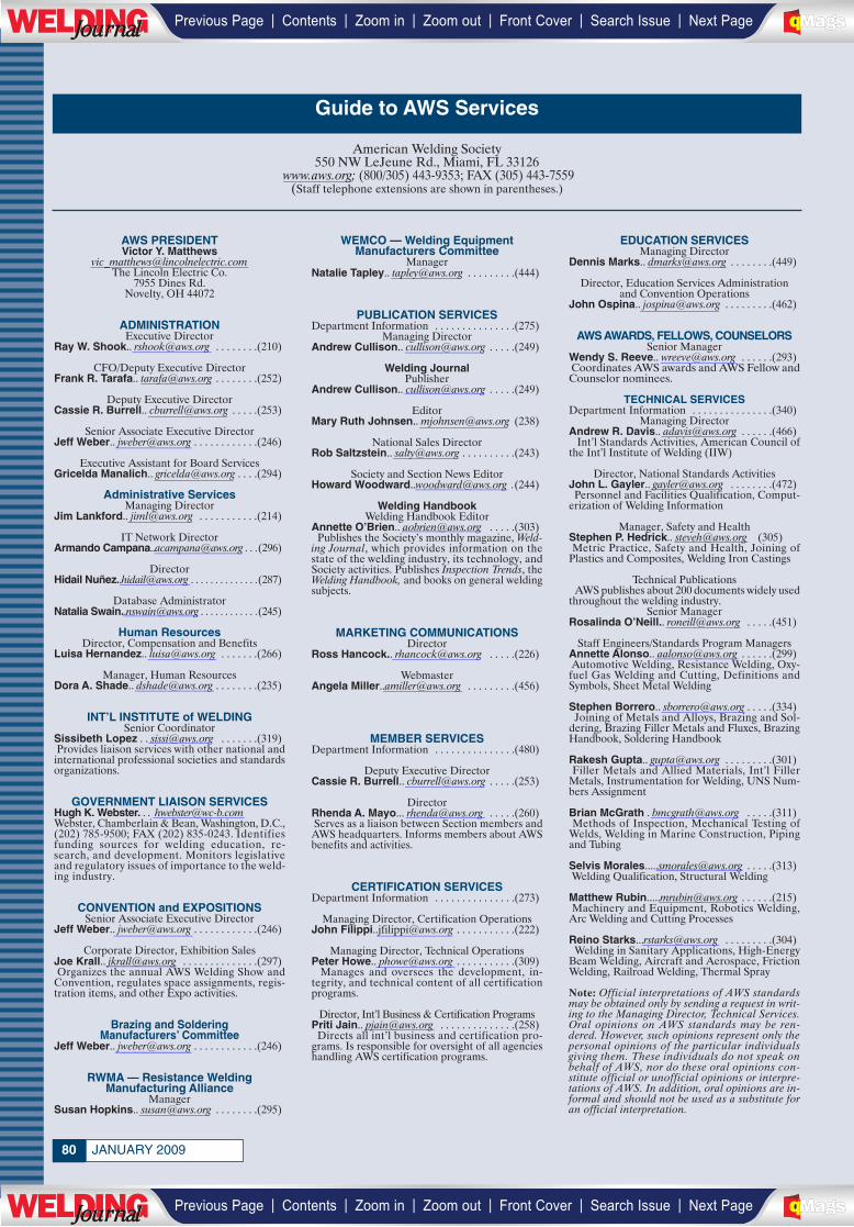
JANUARY 200980
AWS PRESIDENTVictor Y. Matthews
[email protected] Lincoln Electric Co.
7955 Dines Rd.Novelty, OH 44072
ADMINISTRATIONExecutive Director
Ray W. Shook.. [email protected] . . . . . . . .(210)
CFO/Deputy Executive DirectorFrank R. Tarafa.. [email protected] . . . . . . . .(252)
Deputy Executive DirectorCassie R. Burrell.. [email protected] . . . . .(253)
Senior Associate Executive DirectorJeff Weber.. [email protected] . . . . . . . . . . . .(246)
Executive Assistant for Board ServicesGricelda Manalich.. [email protected] . . . .(294)
Administrative ServicesManaging Director
Jim Lankford.. [email protected] . . . . . . . . . . .(214)
IT Network DirectorArmando [email protected] . . .(296)
DirectorHidail Nuñ[email protected] . . . . . . . . . . . . . .(287)
Database AdministratorNatalia [email protected] . . . . . . . . . . . .(245)
Human ResourcesDirector, Compensation and Benefits
Luisa Hernandez.. [email protected] . . . . . . .(266)
Manager, Human Resources Dora A. Shade.. [email protected] . . . . . . . .(235)
INT’L INSTITUTE of WELDINGSenior Coordinator
Sissibeth Lopez . . [email protected] . . . . . . .(319)Provides liaison services with other national andinternational professional societies and standardsorganizations.
GOVERNMENT LIAISON SERVICESHugh K. Webster. . . [email protected], Chamberlain & Bean, Washington, D.C.,(202) 785-9500; FAX (202) 835-0243. Identifiesfunding sources for welding education, re-search, and development. Monitors legislativeand regulatory issues of importance to the weld-ing industry.
CONVENTION and EXPOSITIONSSenior Associate Executive Director
Jeff Weber.. [email protected] . . . . . . . . . . . .(246)
Corporate Director, Exhibition SalesJoe Krall.. [email protected] . . . . . . . . . . . . . .(297)Organizes the annual AWS Welding Show and
Convention, regulates space assignments, regis-tration items, and other Expo activities.
Brazing and Soldering Manufacturers’ Committee
Jeff Weber.. [email protected] . . . . . . . . . . . .(246)
RWMA — Resistance Welding Manufacturing Alliance
ManagerSusan Hopkins.. [email protected] . . . . . . . .(295)
WEMCO — Welding EquipmentManufacturers Committee
ManagerNatalie Tapley.. [email protected] . . . . . . . . .(444)
PUBLICATION SERVICESDepartment Information . . . . . . . . . . . . . . .(275)
Managing DirectorAndrew Cullison.. [email protected] . . . . .(249)
Welding JournalPublisher
Andrew Cullison.. [email protected] . . . . .(249)
EditorMary Ruth Johnsen.. [email protected] (238)
National Sales DirectorRob Saltzstein.. [email protected] . . . . . . . . . .(243)
Society and Section News EditorHoward [email protected] .(244)
Welding HandbookWelding Handbook Editor
Annette O’Brien.. [email protected] . . . . .(303)Publishes the Society’s monthly magazine, Weld-
ing Journal, which provides information on thestate of the welding industry, its technology, andSociety activities. Publishes Inspection Trends, theWelding Handbook, and books on general weldingsubjects.
MARKETING COMMUNICATIONSDirector
Ross Hancock.. [email protected] . . . . .(226)
WebmasterAngela [email protected] . . . . . . . . .(456)
MEMBER SERVICESDepartment Information . . . . . . . . . . . . . . .(480)
Deputy Executive DirectorCassie R. Burrell.. [email protected] . . . . .(253)
DirectorRhenda A. Mayo... [email protected] . . . . .(260) Serves as a liaison between Section members and
AWS headquarters. Informs members about AWSbenefits and activities.
CERTIFICATION SERVICESDepartment Information . . . . . . . . . . . . . . .(273)
Managing Director, Certification OperationsJohn [email protected] . . . . . . . . . . .(222)
Managing Director, Technical OperationsPeter Howe.. [email protected] . . . . . . . . . . .(309)
Manages and oversees the development, in-tegrity, and technical content of all certificationprograms.
Director, Int’l Business & Certification ProgramsPriti Jain.. [email protected] . . . . . . . . . . . . . .(258)
Directs all int’l business and certification pro-grams. Is responsible for oversight of all agencieshandling AWS certification programs.
EDUCATION SERVICES Managing Director
Dennis Marks.. [email protected] . . . . . . . .(449)
Director, Education Services Administrationand Convention Operations
John Ospina.. [email protected] . . . . . . . . .(462)
AWS AWARDS, FELLOWS, COUNSELORSSenior Manager
Wendy S. Reeve.. [email protected] . . . . . .(293)Coordinates AWS awards and AWS Fellow andCounselor nominees.
TECHNICAL SERVICESDepartment Information . . . . . . . . . . . . . . .(340)
Managing DirectorAndrew R. Davis.. [email protected] . . . . . .(466)
Int’l Standards Activities, American Council ofthe Int’l Institute of Welding (IIW)
Director, National Standards ActivitiesJohn L. Gayler.. [email protected] . . . . . . . .(472)Personnel and Facilities Qualification, Comput-
erization of Welding Information
Manager, Safety and HealthStephen P. Hedrick.. [email protected] (305)Metric Practice, Safety and Health, Joining of
Plastics and Composites, Welding Iron Castings
Technical PublicationsAWS publishes about 200 documents widely used
throughout the welding industry.Senior Manager
Rosalinda O’Neill.. [email protected] . . . . .(451)
Staff Engineers/Standards Program ManagersAnnette Alonso.. [email protected] . . . . . .(299)Automotive Welding, Resistance Welding, Oxy-fuel Gas Welding and Cutting, Definitions andSymbols, Sheet Metal Welding
Stephen Borrero.. [email protected] . . . . .(334)Joining of Metals and Alloys, Brazing and Sol-
dering, Brazing Filler Metals and Fluxes, BrazingHandbook, Soldering Handbook
Rakesh Gupta.. [email protected] . . . . . . . . .(301)Filler Metals and Allied Materials, Int’l Filler
Metals, Instrumentation for Welding, UNS Num-bers Assignment
Brian McGrath . [email protected] . . . . .(311)Methods of Inspection, Mechanical Testing of
Welds, Welding in Marine Construction, Pipingand Tubing
Selvis [email protected] . . . . .(313)Welding Qualification, Structural Welding
Matthew [email protected] . . . . . .(215)Machinery and Equipment, Robotics Welding,
Arc Welding and Cutting Processes
Reino [email protected] . . . . . . . . .(304)Welding in Sanitary Applications, High-Energy
Beam Welding, Aircraft and Aerospace, FrictionWelding, Railroad Welding, Thermal Spray
Note: Official interpretations of AWS standardsmay be obtained only by sending a request in writ-ing to the Managing Director, Technical Services.Oral opinions on AWS standards may be ren-dered. However, such opinions represent only thepersonal opinions of the particular individualsgiving them. These individuals do not speak onbehalf of AWS, nor do these oral opinions con-stitute official or unofficial opinions or interpre-tations of AWS. In addition, oral opinions are in-formal and should not be used as a substitute foran official interpretation.
Guide to AWS Services
American Welding Society550 NW LeJeune Rd., Miami, FL 33126
www.aws.org; (800/305) 443-9353; FAX (305) 443-7559(Staff telephone extensions are shown in parentheses.)
__________________
_________
________
_________
_________
_________
_______
__________
________
_________
_________
__________
_______
__________
_________
________
________
________
_________
_______
__________
_________
________
_________
________
__________
_________
_________
_________
________
________
________
_________
_________
________
________
________
________
________
_________
_________
________
__________
_________
_________
________
| | | | | |Previous Page Contents Zoom in Zoom out Front Cover Search Issue Next PageLWE DINGJournalJournal BA
M SaGEF
| | | | | |Previous Page Contents Zoom in Zoom out Front Cover Search Issue Next PageLWE DINGJournalJournal BA
M SaGEF
________
81WELDING JOURNAL
Only Sustaining Members, Members,Honorary Members, Life Members, orRetired Members who have been mem-bers for a period of at least three yearsshall be eligible for election as a directoror national officer.
It is the duty of the National Nominat-ing Committee to nominate candidates fornational office. The committee shall holdan open meeting, preferably at the AnnualMeeting, at which members may appearto present and discuss the eligibility of allcandidates.
To be considered a candidate for the po-sitions of president, vice president, treas-urer, or director-at-large, the followingqualifications and conditions apply:
President: To be eligible to hold the of-fice of president, an individual must haveserved as a vice president for at leastone year.
Vice President: To be eligible to hold theoffice of vice president, an individual musthave served at least one year as a director,other than executive director and secretary.
Treasurer: To be eligible to hold the
office of treasurer, an individual must bea member of the Society, other than a Stu-dent Member, must be frequently avail-able to the national office, and should beof executive status in business or industrywith experience in financial affairs.
Director-at-Large: To be eligible forelection as a director-at-large, an individ-ual shall previously have held office aschairman of a Section; as chairman orvice chairman of a standing, technical,or special committee of the Society; oras a District director.
Interested persons should submit a let-ter stating which office they seek, includinga statement of qualifications, their willing-ness and ability to serve if nominated andelected, and a biographical sketch.
E-mail the letter to Gricelda Manalich,[email protected], c/o Gene Lawson,chair, National Nominating Committee.
The next meeting of the NationalNominating Committee is scheduled forNovember 2009. The terms of office forcandidates nominated at this meeting willcommence January 1, 2011.
William Irrgang Memorial AwardSponsored by The Lincoln Electric Co.
in honor of William Irrgang, the award,adminstered by AWS, is given each yearto the individual who has done the mostover the past five years to enhance the So-ciety’s goal of advancing the science andtechnology of welding. It includes a $2500honorarium and a certificate.
George E. Willis AwardSponsored by The Lincoln Electric Co.
in honor of George E. Willis, the award,adminstered by AWS, is given each yearto an individual who promoted the ad-vancement of welding internationally byfostering cooperative participation intechnology transfer, standards rationali-zation, and promotion of industrial good-will. It includes a $2500 honorarium anda certificate.
Honorary Membership AwardThe honor is presented to a person of
acknowledged eminence in the welding
profession, or to one who is accreditedwith exceptional accomplishments in thedevelopment of the welding art, uponwhom the Society deems fit to confer anhonorary distinction. Honorary Membershave full rights of membership.
National Meritorious Certificate AwardThis certificate award recognizes the re-
cipient’s counsel, loyalty, and dedicationto AWS affairs, assistance in promotingcordial relations with industry and otherorganizations, and for contributions of timeand effort on behalf of the Society.
International Meritorious Certificate Award
This honor recognizes recipients’ sig-nificant contributions to the welding in-dustry for service to the internationalwelding community in the broadest terms.The awardee is not required to be an AWSmember. Multiple awards may be given.The award consists of a certificate and aone-year AWS membership.
AWS Publications Sales
Purchase AWS standards, books, and other publications from
World Engineering Xchange (WEX), [email protected]; www.awspubs.comToll-free (888) 935-3464 (U.S., Canada)
(305) 824-1177; FAX (305) 826-6195
Welding Journal ReprintsCopies of Welding Journal articles may be
purchased from Ruben Lara. (800/305) 443-9353, ext. 288; [email protected]
Custom reprints of Welding Journalarticles, in quantities of 100 or more,
may be purchased from FosteReprints
Claudia StachowiakReprint Marketing Manager
866-879-9144, ext. [email protected]
AWS Mission Statement
The mission of the American WeldingSociety is to advance the science,
technology, and application of welding and allied processes,
including joining, brazing, soldering, cutting, and thermal spraying.
It is the intent of the American WeldingSociety to build AWS to the highest qual-ity standards. Your suggestions are wel-come. Please contact any staff member orAWS President Victor Y. Matthews, aslisted on the previous page.
AWS FoundationAWS Foundation, Inc., is a not-for-profit cor-poration established to provide support foreducational and scientific endeavors of theAmerican Welding Society. Information ongift-giving programs is available upon request.
Chairman, Board of TrusteesGerald D. Uttrachi
Executive Director, AWSRay Shook, ext. 210, [email protected]
Executive Director, FoundationSam Gentry, ext. 331, [email protected]
Corporate Director, Solutions OpportunitySquad
Monica Pfarr, ext. 461, [email protected]
Director, Solutions Opportunity SquadConnie Bowling, ext. 308, [email protected]
550 NW LeJeune Rd., Miami, FL 33126(305) 445-6628; (800) 443-9353, ext. 293
General Information:(800) 443-9353, ext. 689; [email protected]
The Honorary Meritorious AwardsCommittee makes recommendations forthe nominees presented to receive theHonorary Membership, NationalMeritorious Certificate, William IrrgangMemorial, and the George E. WillisAwards. These honors are presented dur-ing the FABTECH International & AWS
Welding Show held each fall. The dead-line for submissions is December 31 priorto the year of the awards presentations.Send candidate materials to Wendy SueReeve, secretary, Honorary MeritoriousAwards Committee, [email protected]; 550NW LeJeune Rd., Miami, FL 33126.Descriptions of these awards follow.
Honorary Meritorious Awards
Nominees for National Office
_________
____________
________________
____________
__________
__________
_________
_________
__________
__________
| | | | | |Previous Page Contents Zoom in Zoom out Front Cover Search Issue Next PageLWE DINGJournalJournal BA
M SaGEF
| | | | | |Previous Page Contents Zoom in Zoom out Front Cover Search Issue Next PageLWE DINGJournalJournal BA
M SaGEF
__________
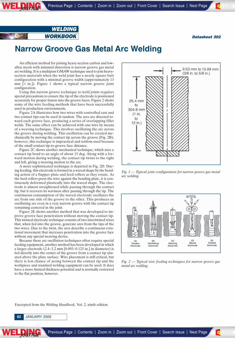
WELDINGWORKBOOK
An efficient method for joining heavy-section carbon and low-alloy steels with minimal distortion is narrow groove gas metalarc welding. It is a multipass GMAW technique used to join heavy-section materials when the weld joint has a nearly square buttconfiguration with a minimal groove width (approximately 13mm [1⁄2 in.]). Figure 1 shows a typical narrow groove jointconfiguration.
Using this narrow groove technique to weld joints requiresspecial precautions to ensure the tip of the electrode is positionedaccurately for proper fusion into the groove faces. Figure 2 showssome of the wire feeding methods that have been successfullyused in production environments.
Figure 2A illustrates how two wires with controlled cast andtwo contact tips can be used in tandem. The arcs are directed to-ward each groove face, producing a series of overlapping filletwelds. The same effect can be achieved with one wire by meansof a weaving technique. This involves oscillating the arc acrossthe groove during welding. This oscillation can be created me-chanically by moving the contact tip across the groove (Fig. 2B);however, this technique is impractical and seldom used becauseof the small contact tip-to-groove face distance.
Figure 2C shows another mechanical technique, which uses acontact tip bend to an angle of about 15 deg. Along with a for-ward motion during welding, the contact tip twists to the rightand left, giving a weaving motion to the arc.
A more sophisticated technique is depicted in Fig. 2D. Dur-ing feeding, this electrode is formed in a waved shape by the bend-ing action of a flapper plate and feed rollers as they rotate. Asthe feed rollers press the wire against the bending plate, it is con-tinuously deformed plastically into the waved shape. The elec-trode is almost straightened while passing through the contacttip, but it recovers its waviness after passing through the tip. Thecontinuous consumption of the waved electrode oscillates thearc from one side of the groove to the other. This produces anoscillating arc even in a very narrow groove with the contact tipremaining centered in the joint.
Figure 2E shows another method that was developed to im-prove groove face penetration without moving the contact tip.This twisted electrode technique consists of two intertwined wiresthat, when fed into the groove, generate arcs from the tips of thetwo wires. Due to the twist, the arcs describe a continuous rota-tional movement that increases penetration into the groove facewithout any special weaving device.
Because these arc oscillation techniques often require specialfeeding equipment, another method has been developed in whicha larger electrode (2.4–3.2 mm [0.093–0.125 in.] in diameter) isfed directly into the center of the groove from a contact tip situ-ated above the plate surface. Wire placement is still critical, butthere is less chance of arcing between the contact tip and theworkpiece and standard welding equipment can be used. It doeshave a more limited thickness potential and is normally restrictedto the flat position, however.
JANUARY 200982
Datasheet 302
Excerpted from the Welding Handbook, Vol. 2, ninth edition.
Narrow Groove Gas Metal Arc Welding
Fig. 1 — Typical joint configuration for narrow groove gas metalarc welding.
Fig. 2 — Typical wire feeding techniques for narrow groove gasmetal arc welding.
| | | | | |Previous Page Contents Zoom in Zoom out Front Cover Search Issue Next PageLWE DINGJournalJournal BA
M SaGEF
| | | | | |Previous Page Contents Zoom in Zoom out Front Cover Search Issue Next PageLWE DINGJournalJournal BA
M SaGEF

AWS FELLOWSHIPS
To: Professors Engaged in Joining Research
Subject: Request for Proposals for AWS Fellowships for the 2009-2010 Academic Year
The American Welding Society (AWS) seeks to foster university research in joining and to recognize outstanding faculty and student talent. We are again requesting your proposals for consideration by AWS. It is expected that the winning researchers will take advantage of the opportunity to work with industry committees interested in the research topics and report work in progress. Please note, there are important changes in the schedule which you must follow in order to enable the awards to be made in a timely fashion. Proposals must be received at American Welding Society by February 17, 2009. New AWS Fellowships will be announced at the AWS Annual Meeting, November 2009.
THE AWARDS
The Fellowships or Grants are to be in amounts of up to $25,000 per year. A maximum of four students are funded for a period of up to three years of research at any one time. However, progress reports and requests for renewal must be submitted for the second and third years. Renewal by AWS will be contingent on demonstration of reasonable progress in the research or in graduate studies. The AWS Fellowship is awarded to the student for graduate research toward a Masters or Ph.D. Degree under a sponsoring professor at a North American University. The qualifications of the Graduate Student are key elements to be considered in the award. The academic credentials, plans and research history (if any) of the student should be provided. The student must prepare the proposal for
the AWS Fellowship. However, the proposal must be under the auspices of a professor and accompanied by one or more letters of recommendation from the sponsoring professor or others acquainted with the student's technical capabilities. Topics for the AWS Fellowship may span the full range of the joining industry. Should the student selected by AWS be unable to accept the Fellowship or continue with the research at any time during the period of the award, the award will be forfeited and no (further) funding provided by AWS. The bulk of AWS funding should be for student support. AWS reserves the right not to make awards in the event that its Committee finds all candidates unsatisfactory.
DETAILS
The Proposal should include:
1. Executive Summary 2. Annualized Breakdown of Funding Required and Purpose of Funds (Student Salary, Tuition, etc.) 3. Matching Funding or Other Support for Intended Research 4. Duration of Project 5. Statement of Problem and Objectives 6. Current Status of Relevant Research 7. Technical Plan of Action 8. Qualifications of Researchers 9. Pertinent Literature References and Related Publications 10. Special Equipment Required and Availability 11. Statement of Critical Issues Which Will Influence Success or Failure of Research
In addition, the proposal must include:
1. Student's Academic History, Resume and Transcript 2. Recommendation(s) Indicating Qualifications for Research must include one or more letters of recommendation from the sponsoring professor or others acquainted with the student's technical capabilities 3. Brief Section or Commentary on Importance of Research to the Welding Community and to AWS, Including Technical Merit, National Need, Long Term Benefits, etc. 4. Statement Regarding Probability of Success
The technical portion of the Proposal should be about ten typewritten pages; maximum pages for the Proposal should be twenty-five typewritten pages. Maximum file size should be 2 megabytes. It is recommended that the Proposal be typed in a minimum of 12-point font in Times, Times New Roman, or equivalent. Proposal should be sent electronically by February 17, 2009 to: Vicki Pinsky ([email protected]) Manager, AWS Foundation American Welding Society 550 N.W. LeJeune Rd., Miami, FL 33126
Yours sincerely,
Ray W. Shook Executive Director American Welding Society
| | | | | |Previous Page Contents Zoom in Zoom out Front Cover Search Issue Next PageLWE DINGJournalJournal BA
M SaGEF
| | | | | |Previous Page Contents Zoom in Zoom out Front Cover Search Issue Next PageLWE DINGJournalJournal BA
M SaGEF
Friends and Colleagues:
The American Welding Society established the honor of Counselor to recognize individual membersfor a career of distinguished organizational leadership that has enhanced the image and impact of thewelding industry. Election as a Counselor shall be based on an individual’s career of outstandingaccomplishment.
To be eligible for appointment, an individual shall have demonstrated his or her leadership in thewelding industry by one or more of the following:
• Leadership of or within an organization that has made a substantial contribution to the weldingindustry. The individual’s organization shall have shown an ongoing commitment to the industry, asevidenced by support of participation of its employees in industry activities.
• Leadership of or within an organization that has made a substantial contribution to training andvocational education in the welding industry. The individual’s organization shall have shown an ongoingcommitment to the industry, as evidenced by support of participation of its employee in industry activities.
For specifics on the nomination requirements, please contact Wendy Sue Reeve at AWS headquartersin Miami, or simply follow the instructions on the Counselor nomination form in this issue of the WeldingJournal. The deadline for submission is July 1, 2009. The committee looks forward to receiving thesenominations for 2010 consideration.
Sincerely,
Alfred F. FleuryChair, Counselor Selection Committee
| | | | | |Previous Page Contents Zoom in Zoom out Front Cover Search Issue Next PageLWE DINGJournalJournal BA
M SaGEF
| | | | | |Previous Page Contents Zoom in Zoom out Front Cover Search Issue Next PageLWE DINGJournalJournal BA
M SaGEF
(please type or print in black ink)
COUNSELOR NOMINATION FORM
DATE_________________NAME OF CANDIDATE________________________________________________________________________
AWS MEMBER NO.___________________________YEARS OF AWS MEMBERSHIP____________________________________________
HOME ADDRESS____________________________________________________________________________________________________
CITY_______________________________________________STATE________ZIP CODE__________PHONE________________________
PRESENT COMPANY/INSTITUTION AFFILIATION_______________________________________________________________________
TITLE/POSITION____________________________________________________________________________________________________
BUSINESS ADDRESS________________________________________________________________________________________________
CITY______________________________________________STATE________ZIP CODE__________PHONE_________________________
ACADEMIC BACKGROUND, AS APPLICABLE:
INSTITUTION______________________________________________________________________________________________________
MAJOR & MINOR__________________________________________________________________________________________________
DEGREES OR CERTIFICATES/YEAR____________________________________________________________________________________
LICENSED PROFESSIONAL ENGINEER: YES_________NO__________ STATE______________________________________________
SIGNIFICANT WORK EXPERIENCE:
COMPANY/CITY/STATE_____________________________________________________________________________________________
POSITION____________________________________________________________________________YEARS_______________________
COMPANY/CITY/STATE_____________________________________________________________________________________________
POSITION____________________________________________________________________________YEARS_______________________
SUMMARIZE MAJOR CONTRIBUTIONS IN THESE POSITIONS:
__________________________________________________________________________________________________________________
__________________________________________________________________________________________________________________
__________________________________________________________________________________________________________________IT IS MANDATORY THAT A CITATION (50 TO 100 WORDS, USE SEPARATE SHEET) INDICATING WHY THE NOMINEE SHOULD BESELECTED AS AN AWS COUNSELOR ACCOMPANY THE NOMINATION PACKET. IF NOMINEE IS SELECTED, THIS STATEMENT MAYBE INCORPORATED WITHIN THE CITATION CERTIFICATE.
**MOST IMPORTANT**The Counselor Selection Committee criteria are strongly based on and extracted from the categories identified below. All in-
formation and support material provided by the candidate’s Counselor Proposer, Nominating Members and peers are considered.
SUBMITTED BY: PROPOSER_______________________________________________AWS Member No.___________________The proposer will serve as the contact if the Selection Committee requires further information. The proposer is encouraged to include adetailed biography of the candidate and letters of recommendation from individuals describing the specific accomplishments of the can-didate. Signatures on this nominating form, or supporting letters from each nominator, are required from four AWS members in additionto the proposer. Signatures may be acquired by photocopying the original and transmitting to each nominating member. Once the sig-natures are secured, the total package should be submitted.
NOMINATING MEMBER:___________________________________Print Name___________________________________AWS Member No.______________
NOMINATING MEMBER:___________________________________Print Name___________________________________AWS Member No.______________
NOMINATING MEMBER:___________________________________Print Name___________________________________AWS Member No.______________
NOMINATING MEMBER:___________________________________Print Name___________________________________AWS Member No.______________
CLASS OF 2010
SUBMISSION DEADLINE JULY 1, 2009
| | | | | |Previous Page Contents Zoom in Zoom out Front Cover Search Issue Next PageLWE DINGJournalJournal BA
M SaGEF
| | | | | |Previous Page Contents Zoom in Zoom out Front Cover Search Issue Next PageLWE DINGJournalJournal BA
M SaGEF
Nomination of AWS Counselor
I. HISTORY AND BACKGROUNDIn 1999, the American Welding Society established the honor of Counselor to recognize indi-
vidual members for a career of distinguished organizational leadership that has enhanced theimage and impact of the welding industry. Election as a Counselor shall be based on anindividual’s career of outstanding accomplishment.
To be eligible for appointment, an individual shall have demonstrated his or her leadership inthe welding industry by one or more of the following:
• Leadership of or within an organization that has made a substantial contribution to the welding industry. (The individual’s organization shall have shown an ongoing commitment to the industry, as evidenced by support of participation of its employeesin industry activities such as AWS, IIW, WRC, SkillsUSA, NEMA, NSRP SP7 or other similar groups.)
• Leadership of or within an organization that has made substantial contribution to trainingand vocational education in the welding industry. (The individual’s organization shall have shown an ongoing commitment to the industry, as evidenced by support of participation of its employees in industry activities such as AWS, IIW, WRC, SkillsUSA, NEMA,NSRP SP7 or other similar groups.)
II. RULESA. Candidates for Counselor shall have at least 10 years of membership in AWS.B. Each candidate for Counselor shall be nominated by at least five members of
the Society.C. Nominations shall be submitted on the official form available from AWS
headquarters.D. Nominations must be submitted to AWS headquarters no later than July 1
of the year prior to that in which the award is to be presented.E. Nominations shall remain valid for three years.F. All information on nominees will be held in strict confidence.G. Candidates who have been elected as Fellows of AWS shall not be eligible for
election as Counselors. Candidates may not be nominated for both of these awards at the same time.
III. NUMBER OF COUNSELORS TO BE SELECTEDMaximum of 10 Counselors selected each year.
Return completed Counselor nomination package to:
Wendy S. ReeveAmerican Welding SocietySenior ManagerAward Programs and Administrative Support550 N.W. LeJeune RoadMiami, FL 33126
Telephone: 800-443-9353, extension 293
SUBMISSION DEADLINE: July 1, 2009
| | | | | |Previous Page Contents Zoom in Zoom out Front Cover Search Issue Next PageLWE DINGJournalJournal BA
M SaGEF
| | | | | |Previous Page Contents Zoom in Zoom out Front Cover Search Issue Next PageLWE DINGJournalJournal BA
M SaGEF
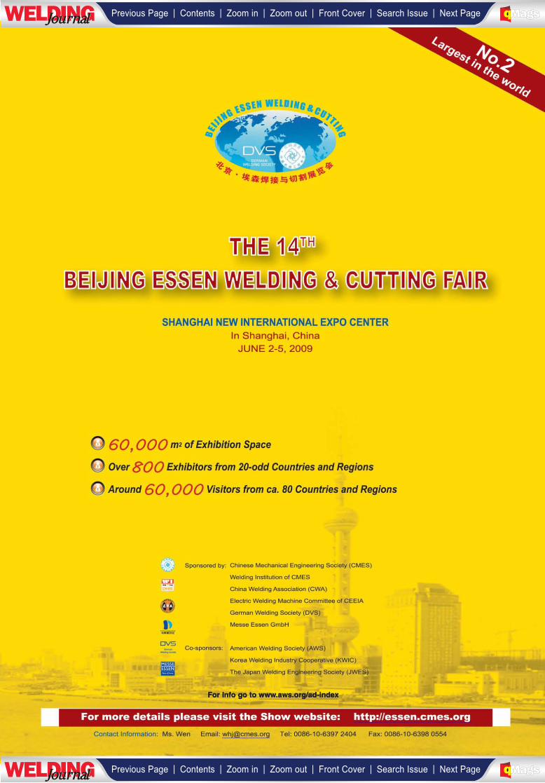
For Info go to www.aws.org/ad-index
________
| | | | | |Previous Page Contents Zoom in Zoom out Front Cover Search Issue Next PageLWE DINGJournalJournal BA
M SaGEF
| | | | | |Previous Page Contents Zoom in Zoom out Front Cover Search Issue Next PageLWE DINGJournalJournal BA
M SaGEF
______________
_____________________
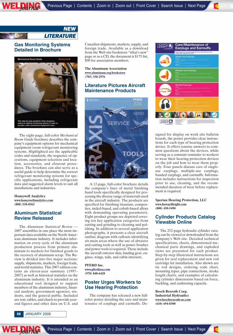
NEWLITERATURE
Gas Monitoring SystemsDetailed in Brochure
The eight-page, full-color MechanicalRoom Guide brochure describes the com-pany’s equipment options for mechanicalequipment room refrigerant monitoringsystems. Highlighted are the applicablecodes and standards, the sequence of op-erations, equipment selection and loca-tion, accessories, and closeout proce-dures. The brochure can also serve as auseful guide to help determine the correctrefrigerant monitoring systems for spe-cific applications, including refrigerantdata and suggested alarm levels to suit allinstallations and industries.
Honeywell Analyticswww.honeywellanalytics.com(800) 538-0363
Aluminum StatisticalReview Released
The Aluminum Statistical Review —2007 assembles in one place the most im-portant data available on the North Amer-ican aluminum industry. It includes infor-mation on every cycle of the aluminumproduction process from primary alu-minum to markets for finished goods tothe recovery of aluminum scrap. The Re-view is divided into five major sections:supply, shipments, markets, foreign trade,and world statistics. This 2007 edition con-tains an eleven-year summary (1997–2007) as well as historical statistics on thealuminum industry. It is intended as aneducational tool designed to supportmembers of the aluminum industry, finan-cial analysts, government agencies, stu-dents, and the general public. Includedare text, tables, and charts to provide year-end figures and other data on U.S. and
Canadian shipments, markets, supply, andforeign trade. Available as a downloadfrom the Web site bookstore “what’s new”page or as a CD, the document is $175 list,$90 for association members.
The Aluminum Associationwww.aluminum.org/bookstore(703) 358-2976
Literature Pictures AircraftMaintenance Products
A 12-page, full-color brochure detailsthe company’s lines of metal finishinghand tools specifically designed for pro-cessing the diverse range of materials usedin the aircraft industry. The products arespecified for finishing titanium, compos-ites, nickel-based, and cobalt-based alloyswith demanding operating parameters.Eight product groups are depicted cover-ing ten key application categories fromcutting and grinding to cleaning and pol-ishing. In addition to several applicationphotographs, it presents a clear aircraftoutline diagram with callouts identifyingsix main areas where the use of abrasiveand cutting tools as well as power brushesand power tools is required. These includethe aircraft exterior skin, landing gear, en-gines, wings, tails, and cabin interiors.
PFERD Inc.www.pferdusa.com(978) 840-6420
Poster Urges Workers toUse Hearing Protection
The company has released a new full-color poster detailing the care and main-tenance of earplugs and earmuffs. De-
signed for display on work site bulletinboards, the poster provides clear instruc-tions for each type of hearing protectiondevice. It offers concise answers to com-mon questions about the devices, whileserving as a constant reminder to workersto wear their hearing-protection deviceson the job and how to wear them prop-erly. Four panels discuss care of single-use earplugs, multiple-use earplugs,banded earplugs, and earmuffs. Informa-tion includes instructions for inspectionprior to use, cleaning, and the recom-mended duration of wear before replace-ment is required.
Sperian Hearing Protection, LLCwww.howardleight.com(800) 430-5490
Cylinder Products CatalogViewable Online
The 252-page hydraulic cylinder cata-log can be viewed or downloaded from thecompany’s Web site. Detailed technicalspecifications, charts, dimensioned me-chanical parts drawings, and explodedviews are presented for each product.Step-by-step illustrated instructions aregiven for seal replacement and new rodcartridge kit installation. Also shown aretie rod designs, ordering code chart,mounting types, pipe connections, strokelength charts, and examples of calculat-ing cylinder dimensions based on force,buckling, and cushioning capacity.
Bosch Rexroth Corp.Industrial Hydraulicswww.boschrexroth-us.com(610) 694-8300
JANUARY 200988
| | | | | |Previous Page Contents Zoom in Zoom out Front Cover Search Issue Next PageLWE DINGJournalJournal BA
M SaGEF
| | | | | |Previous Page Contents Zoom in Zoom out Front Cover Search Issue Next PageLWE DINGJournalJournal BA
M SaGEF
_____________________________
_________________
___________
_______________
89WELDING JOURNAL
Brochure DetailsHardfacing Equipment
An eight-page, profusely illustrated,full-color brochure details a number ofproducts in the company’s lines of station-ary and portable automated weldingequipment for hardfacing applications.Setups are illustrated for processingpetrochemical valves, screw flights, pipe-forming rolls and large forming rolls forthe steel industry, and crusher rolls. Unitsinclude fully programmable welding pa-rameters and machine functions with mul-tiprocess capability. Shown are variouswelding heads, workpiece holding andmovement systems, fume extraction, andarc shielding boxes with various weld pat-terns including flat, internal rotary, exter-nal rotary, spiral, helix, chevron, sinewave, zig-zag, and square wave.
Welding Alloys (USA) Inc.www.welding-alloys.com/usa/machines(859) 525-0165
D1 Code References Issuedon CD and Book Formats
All 59 standards referenced by AWSD1.1/D1.1M:2008, Structural WeldingCode — Steel, are now available on a CDand in printed copy. The ASTM Standardsfor Welding serves as a handy companionto the D1.1 code to provide the resourcesnecessary for quality professionals, in-spectors, supervisors, and quality-con-scious engineers and managers to inter-pret the D1.1 specification and the testmethods used in the code. The 8.5- × 11-in. soft-cover edition has 450 pages. BothCD and printed editions are priced at$395.
ASTM Internationalwww.astm.org(610) 832-9500
Welding Products CatalogUpdated
A 52-page, well-illustrated catalog up-dates the company’s product lines of mild-steel and low-alloy covered electrodes,steel solid wires, tubular wires, and hard-facing and stainless steel products. Eachelectrode is clearly identified by AWSnumber designation, product description,typical applications, chemical analysis,mechanical properties, Charpy V-notchimpact values, stock diameters with rec-ommended operating current values andtype of current, and approvals and con-formances. Included are detailed graphicand tabular information on welding wirepackaging parameters, short circuit trans-fer welding parameters, and spray trans-fer welding parameters, as well as com-prehensive information on tubular wires.
Hobart Brothers Co.www.hobartbrothers.com(800) 424-1543
NEWS OF THEINDUSTRY
Industry Notes
• Empire Industries Ltd. and theAthabasca Chipewyan First NationHolding Corp. recently announcedthrough their joint ownership ofSorge’s Welding Ltd., they have ac-quired Lemax Machine & Welding,Fort McMurray, Alberta, Canada, for$1.2 million plus working capital.
• At www.olympus-ims.com, Olympus haslaunched a Web site with content on itsmany products; application notes; soft-ware downloads; a PDF library; and aneducational theory section.
• Patent US 7,434,491 B1 dated Oct. 14,2008, has been assigned to MotomanInc., Dayton, Ohio, for the Moto-Mount® compliant tool mounting sys-tem with George Sutton Jr., Donald J.Metz, and Daniel W. Slanker named asthe inventors.
• An in-line U-Bend manufacturing cen-ter has been incorporated in RathGib-son’s Janesville, Wis., facility. The sys-tem includes a laser mill, bright an-nealing, U-Bender, and drawing.
• MagneGas Corp., Tampa, Fla., hassigned an agreement with Boca BioFu-els, Inc. to distribute MagneGas for themetal cutting and welding market inthe Greater Atlanta area.
• When the Fox Cities Chamber of Com-merce and Industry, Inc., Appleton,Wis., presented its 2008 Manufacturerof the Year Awards, PerformanceWelding, Inc. won the Small Manufac-turer Category.
• More than 40 distributors attendedAirco Distributor Association’s 13thannual meeting held recently in LasVegas, Nev. Among its highlights weresessions to discuss product lines.
• Jergens, Inc., Cleveland, Ohio, has ac-quired Bock Workholding Inc. withU.S. headquarters in Ford City, Pa.,and sales partners in Europe, Asia, andAustralia.
• Under the American Chemistry Coun-cil’s Responsible Care® program,Linde North America has received cer-tification of its Vancouver, Wash., man-ufacturing facility and its South Bend,Ind., carbon dioxide plant.
— continued from page 11
| | | | | |Previous Page Contents Zoom in Zoom out Front Cover Search Issue Next PageLWE DINGJournalJournal BA
M SaGEF
| | | | | |Previous Page Contents Zoom in Zoom out Front Cover Search Issue Next PageLWE DINGJournalJournal BA
M SaGEF
______________________
________
______________
______________
1 of 2
PROFESSIONAL PROGRAM ABSTRACT SUBMITTAL Annual FABTECH International & AWS Welding Show
Chicago, IL – November 15-18, 2009
Submission Deadline: March 13, 2009
(Complete a separate submittal for each paper to be presented.) Primary Author (Full Name):
Affiliation:
Mailing Address:
City: State/Province Zip/Mail Code Country:
Email:
Co-Author(s):
Name (Full Name): Affiliation Address: City: State/Province Zip/Mail Code Country: E-Mail:
Name (Full Name): Affiliation: Address:
City: State/Province: Zip/Mail Code: Country: E-Mail:
Name (Full Name): Affiliation: Address:
City: State/Province: Zip/Mail Code: Country: E-Mail:
Name (Full Name): Affiliation: Address:
City: State/Province: Zip/Mail Code: Country: E-Mail:
Answer the following about this paper Original submittal? Yes No Progress report? Yes No Review paper? Yes No Tutorial? Yes NoWhat are the welding/Joining processes used? What are the materials used? What is the main emphasis of this paper? Process Oriented Materials Oriented Modeling To what industry segments is this paper most applicable? Has material in this paper ever been published or presented previously? Yes No
If “Yes”, when and where? Is this a graduate study related research? Yes No If accepted, will the author(s) present this paper in person? Yes Maybe No
Keywords: Please indicate the top four keywords associated with your research below
Guidelines for abstract submittal and selection criteria: Only those abstracts submitted on this form will be considered. Follow the guidelines and word limits indicated. Complete this form using MSWord. Submit electronically via email to [email protected]
Technical/Research Oriented Applied Technology Education New science or research. Selection based on technical merit. Emphasis is on previously unpublished work in science or engineering relevant to welding, joining and allied processes.
Preference will be given to submittals with clearly communicated benefit to the welding industry.
New or unique applications. Selection based on technical merit. Emphasis is on previously
unpublished work that applies known principles of joining science or engineering in unique ways.
Preference will be given to submittals with clearly communicated benefit to the welding industry.
Innovation in welding education at all levels.
Emphasis is on education/training methods and their successes.
Papers should address overall relevance to the welding industry.
Check the category that best applies:
Technical/Research Oriented Applied Technology Education
| | | | | |Previous Page Contents Zoom in Zoom out Front Cover Search Issue Next PageLWE DINGJournalJournal BA
M SaGEF
| | | | | |Previous Page Contents Zoom in Zoom out Front Cover Search Issue Next PageLWE DINGJournalJournal BA
M SaGEF
2 of 2
Proposed Title (max. 50 characters): Proposed Subtitle (max. 50 characters):
Abstract: Introduction (100 words max.) – Describe the subject of the presentation, problem/issue being addressed and its practical implications for the welding industry. Describe the basic value to the welding community with reference to specific communities or industry sectors.
Technical Approach, for technical papers only (100 words max.) – Explain the technical approach, experimental methods and the reasons why this approach was taken.
Results/Discussion (300 words max.) – For technical papers, summarize the results with emphasis on why the results are new or original, why the results are of value to further advance the welding science, engineering and applications. For applied technology and education papers, elaborate on why this paper is of value to the welding community, describe key aspects of the work developed and how this work benefits the welding industry and education.
.
Conclusions (100 words max.) – Summarize the conclusions and how they could be put to use – how and by whom.
NOTE: Abstract must not exceed one page and must not exceed the recommended word limit given above Note: The Technical Program is not the venue for commercial promotions of a company or a product. All presentations should avoid the use of product trade names. The Welding Show provides ample opportunities for companies to showcase and advertise their processes and products.
Return this form, completed on both sides, to
AWS Education Services Professional Program 2009
550 NW LeJeune Road Miami FL 33126
FAX 305-648-1655
MUST BE RECEIVED NO LATER THAN MARCH 13, 2009
| | | | | |Previous Page Contents Zoom in Zoom out Front Cover Search Issue Next PageLWE DINGJournalJournal BA
M SaGEF
| | | | | |Previous Page Contents Zoom in Zoom out Front Cover Search Issue Next PageLWE DINGJournalJournal BA
M SaGEF
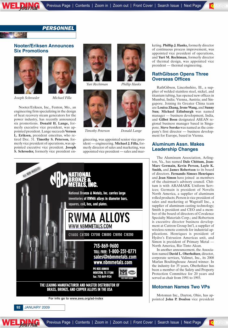
Nooter/Eriksen AnnouncesSix Promotions
Nooter/Eriksen, Inc., Fenton, Mo., anengineering firm specializing in the designof heat recovery steam generators for thepower industry, has recently announcedsix promotions. Donald H. Lange, for-merly executive vice president, was ap-pointed president. Lange succeeds VernonL. Eriksen, president emeritus, who re-tired Dec. 31. Timothy S. Peterson, for-merly vice president of operations, was ap-pointed executive vice president. JosephS. Schroeder, formerly vice president en-
gineering, was appointed senior vice pres-ident — engineering. Michael J. Filla, for-merly director of sales and marketing, wasappointed vice president — sales and mar-
keting. Phillip J. Hanks, formerly directorof continuous process improvement, wasappointed vice president of operations,and Yuri M. Rechtman, formerly directorof thermal design, was appointed vicepresident — thermal engineering.
RathGibson Opens ThreeOverseas Offices
RathGibson, Lincolnshire, Ill., a sup-plier of welded stainless steel, nickel, andtitanium tubing, has opened new offices inMumbai, India; Vienna, Austria; and Sin-gapore. Joining its Greater China teamare Louisa Zhang, Irene Wang, and SunnySun; Michael Edinburgh was namedmanager — business development, India,and Gilbet Boon designated ASEAN re-gional business manager based in Singa-pore. Steve Soroko was named as the com-pany’s first director — business develop-ment for Europe, based in Vienna.
Aluminum Assn. MakesLeadership Changes
The Aluminum Association, Arling-ton, Va., has named Dale Chittum, Jean-Marc Germain, Kevin Person, Layle K.Smith, and James Robertson to its boardof directors. Fernando Simoes Henriquesand Jean Simon have joined as membersof the chairman’s advisory council. Chit-tum is with ARAMARK Uniform Serv-ices; Germain is president of NovelisNorth America, a supplier of aluminumrolled products; Person is vice president ofsales and marketing at Wagstaff Inc., asupplier of aluminum casting technology;Smith is president and CEO and a mem-ber of the board of directors of CovalenceSpecialty Materials Corp.; and Robertsonis executive director business develop-ment at Cattron Group Int’l, a supplier ofwireless remote controls for industrial ap-plications. Henriques is president ofHydro’s Extrusion Americas unit, andSimon is president of Primary Metal —North America, Rio Tinto Alcan.
In another announcement, the Associa-tion named David L. Oberholtzer, director,corporate services, Valimet, Inc., its 2008Marlan Boultinghouse Award winner. Inthe industry for 35 years, Oberholtzer hasbeen a member of the Safety and PropertyProtection Committee for 20 years andserved as chair from 1991 to 1993.
Motoman Names Two VPs
Motoman Inc., Dayton, Ohio, has ap-pointed John P. Donlon vice president
JANUARY 200992
PERSONNEL
Phillip HanksYuri Rechtman
Joseph Schroeder
Timothy Peterson
Michael Filla
Donald Lange
For info go to www.aws.org/ad-index
__________________
| | | | | |Previous Page Contents Zoom in Zoom out Front Cover Search Issue Next PageLWE DINGJournalJournal BA
M SaGEF
| | | | | |Previous Page Contents Zoom in Zoom out Front Cover Search Issue Next PageLWE DINGJournalJournal BA
M SaGEF
__________________
_________________
______________
U.S. sales and Thomas J. Schockman asvice president, finance and accounting,and CFO. Donlon, with more than 28years in the industry, most recently wasvice president, sales and marketing, forUnion Switch & Signal in Pittsburgh, Pa.Schockman previously served as directorof financial planning and analysis and cor-porate controller for Robbins & Myers,Inc., Dayton, Ohio.
Plant Manager Named atWelding Alloys
Welding AlloysGroup, Florence, Ky.,a manufacturer offlux cored weldingwires for hardfacingapplications, hasnamed Tim Ehlmanplant manager. Priorto joining the com-pany, Ehlman wasplant manager at ZFSachs Automotive of
America for 15 years.
Jet Edge Appoints Int’lSales Manager
Jet Edge, Inc., St.Michael, Minn., amanufacturer of ul-trahigh-pressure wa-terjet systems, has ap-pointed David J. An-derson as its new in-ternational salesmanager. In the in-dustry for 15 years,Anderson previouslywas an advisor to U.S.
and foreign businesses regarding riskmanagement, sales processes, and mar-keting management.
Laser Cladding ServicesAppoints President
Gremada Industries, Inc., Houston,Tex., has tapped its vice president of salesand marketing, James P. Kowske, to serve aspresident of its subsidiary, Laser CladdingServices, Ltd. Kowske will continue in hisrole as the company’s vice president.
Navy Metalworking CenterNames Technical Director
The office of Naval Research recentlyapproved the Navy Metalworking Cen-ter’s recommendation to appoint RobertE. Akans technical director. Akans has 24years of experience in the aluminum in-dustry, most recently serving as director,manufacturing technologies, at Concur-rent Technologies Corp.
VP Named at MISTRAS
MISTRAS Group,Inc., Princeton Junc-tion, N.J., has pro-moted Jim Redmonto vice president forits Asset IntegrityManagement Serv-ices Center of Excel-lence. Previously,Redmon was man-ager of the PCMSsoftware division.
Lincoln Electric AppointsTwo VPs
Lincoln Electric Holdings, Inc., Cleve-land, Ohio, has elected Steven B. Hedlundto the newly created position of vice pres-ident, strategy and business development,and Earl L. Ward to the newly created po-sition of vice president, mergers, acquisi-tions, and investor relations. Previously,Hedlund was vice president of growth andinnovation for Master Lock Co. Ward pre-viously was treasurer and vice president ofinvestor relations at the former Washing-ton Group Int’l that is currently known asthe Washington division of URS Corp.
Obituaries
Lawrence Allen Creager
Lawrence Allen Creager died Oct. 2 inFenton, Mo., from complications follow-ing surgery. An AWS member since 1989,Creager served more than 25 years in thewelding industry, holding sales manage-ment positions with Tweco/Arcair, OKIBering, and ABICOR Binzel. He is sur-vived by his wife, Karen, two daughters,and four grandchildren.
Richard Arthur Huber
Richard Arthur(Dick) Huber, 79,died July 22, 2008, athis home in OakRidge, Tenn. AnAWS member since1958 and a LifeMember, he servedas chairman of theNortheast Ten-nessee Section(1978–1979), and asAWS president
(1990–1991). He wasscheduled to receive his Gold MembershipAward for 50 years of service to the Ameri-can Welding Society at the recent AWSWelding Show.
After serving two years in the U.S. Army,Huber became involved with the welding ofpressure vessel steels for Alco Products,Inc., in Schenectady, N.Y. He received hisbachelor’s degree in chemistry from Michi-gan State University in 1952, and his mas-ter’s in metallurgy from Rensselaer Poly-technic Institute in 1959. Later that year hestarted work for Union Carbide (later Ma-rietta Energy Systems, Inc.) Nuclear Div. Y-12 Plant as a welding engineer. In the 1960s,he introduced electron beam welding to thefacility and published several papers on thetopic. In 1972, Huber transferred to the As-sembly Div. as supervisor of the Metallurgi-cal Joining Section, responsible for the pro-duction joining activities of the Y-12 Plant,and later became group leader of the newlycombined Assembly and DevelopmentJoining groups.
Huber was active with St. Stephen’sEpiscopal Church in Oak Ridge, Tenn.,where he served in many capacities, in-cluding driving for F.I.S.H. (Fellowship InServing Humanity).
Flying was his favorite activity. He heldIFR and commercial flying licenses, andpiloted many cross-country flights. A cer-tified scuba diver, Huber also engaged ingolf, tennis, bowling, fishing, and playingduplicate bridge, and was an avid soccerfan for his grandchildren. Following his re-tirement in 1992, he and his wife traveledextensively in their RV, visiting Alaska andtheir far-flung family members. He is sur-vived by his wife, Elaine, four sons,Richard Michael, Timothy Todd, GregoryEvans, Laurence Edward, and Kevin LeeHayes a son they adopted in 1980, threebrothers James, Alan, and Patrick, andseveral nieces and nephews.
Charles Leigh Foster II
Charles Leigh “Chuck” Foster II, 58,died suddenly Nov. 1 in China while trav-eling on business. An AWS member since1985, he was active with the San FranciscoSection. He is survived by his wife Rosalie.
93WELDING JOURNAL
Tim Ehlman
Jim Redmon
Dave Anderson
Earl Ward Steve Hedlund
Richard A. Huber
John DonlonThomas Schockman
| | | | | |Previous Page Contents Zoom in Zoom out Front Cover Search Issue Next PageLWE DINGJournalJournal BA
M SaGEF
| | | | | |Previous Page Contents Zoom in Zoom out Front Cover Search Issue Next PageLWE DINGJournalJournal BA
M SaGEF
AWSFoundationGivesThanks for 2008
Planned giving can make a significant impact on welder workforce issues whileproviding income and other benefits to yourself
Charitable Remainder Unitrust provides a lifetime of rewards:
• Payment to you and/or family and friends• Immediate tax deduction for the value of the remainder interest
• Avoid capital gains tax on any appreciated asset•Future financial resources for the AWS Foundation
Contact us today! 800-443-9353, Ext. [email protected]
© AWS 2008
IndividualsWilma J. AdkinsThe Adkins FamilyBruce and Diane AlbrechtOsama Al-ErhayemRichard AmirikianRoman F. ArnoldyJack R. BarckhoffHil J. BaxDennis and Eddis BlunierD. Fred and Lou BovieWilliam A. and Ann M. BrothersCable Family FoundationAlan ChristophersonJoseph M. and Debbie A. CilliDonald E. and Jean ClevelandJack and Jo DammannMr. and Mrs. J. F. DammannLouis DeFreitasFrank G. DeLaurierWilliam T. DeLongEstate of Esther BaginskyEstate of Boris KrantzFamily of R. D. Thomas, Jr.Richard D. FrenchGlenn J. GibsonJames E. Greer & Adele M. KulikowskiJoyce E. HarrisonDonald F. and Shirley HastingsRobb F. HowellJeffrey R. HufseyJoseph R. JohnsonDeborah H. KurdEarl and Marie LipphardtJ. J. McLaughlinL. William and Judy MyersRobert and Annette O’BrienRobert L. PeasleeJoyce and Ronald C. PierceWerner QuasebarthOren and Donna ReichWilliam and Cherry Rice
Jerome L. RobinsonRobert and Mitzie RoedigerSandy and Ray W. ShookMyron and Ginny StepathCharley A. StoodyJulie S. TheissR. D. Thomas, Jr.James A. Turner, Jr.Gerald and Christine UttrachiNelson WallAmos O. and Marilyn WinsandNannette Zapata
CorporationsAirgasAir Liquide America CorporationAir Products and Chemicals, Inc.American Welding SocietyBohler Thyssen Welding USA, Inc.Caterpillar, Inc.Chemalloy Company, Inc.C-K WorldwideCor-Met, Inc.ESAB Welding & Cutting ProductsEdison Welding InstituteEutetic CastolinThe Fibre-Metal Products CompanyGases and Welding Distributors AssociationGibson Tube, Inc.Malcolm T. Gilliland, Inc.Gullco International, Inc.Harris Calorific, Inc.High Purity GasHobart Brothers Company- Corex- McKay Welding Products- Tri-MarkHobart Institute of Welding TechnologyHypertherm, Inc.Illinois Tool Works CompaniesIndependent Can CompanyInweld Corporation
The Irene & George A. Davis FoundationJ. W. Harris Company, Inc.Jackson SafetyJohn Tillman Co.Kirk FoundationKobelco Welding of America, Inc.The Lincoln Electric CompanyThe Lincoln Electric FoundationMK Products, Inc.Mathey DearmanMatsuo Bridge Co. Ltd.Miller Electric Mfg. Co.Mountain Enterprises, Inc.National Electric Mfg. AssociationNational Welders Supply CompanyNavy Joining CenterNelson Stud WeldingNORCO, Inc.OKI BeringORS NASCO, Inc.OXO Welding Equipment CompanyPferd, Inc.Praxair Distribution, Inc.Resistance Welder Manufacturers’ Assn.Roberts Oxygen Company, Inc.Saf-T-CartSelect-Arc, Inc.SESCOShawnee Steel & Welding, Inc.Shell Chemical LP – WTCSky Cylinder Testing, Inc.Thermadyne Holdings CorporationTri-Tool, Inc.Trinity Industries, Inc.Uvex Safety, Inc.Webster, Chamberlain & BeanWESCO Gas & Welding Supply, Inc.Weld-Aid ProductsWeld Tooling/Bug-O SystemsWeldstar CompanyWestern EnterprisesWolverine Bronze Company
We would like to thank the following major donors who havesupported the AWS Foundation
Planned Giving: Generating a Futurefor the Future Welder Workforce
_______________
| | | | | |Previous Page Contents Zoom in Zoom out Front Cover Search Issue Next PageLWE DINGJournalJournal BA
M SaGEF
| | | | | |Previous Page Contents Zoom in Zoom out Front Cover Search Issue Next PageLWE DINGJournalJournal BA
M SaGEF
National Scholarship ProgramHoward E. and Wilma J. Adkins Memorial
ScholarshipAirgas – Jerry Baker ScholarshipAirgas – Terry Jarvis Memorial
ScholarshipArsham Amirikian Engineering
ScholarshipJack R. Barckhoff Welding Management
ScholarshipsDavid Fred Bovie and Marian Lou Bovie
National ScholarshipEdward J. Brady Memorial ScholarshipWilliam A. and Ann M. Brothers
ScholarshipESAB Welding & Cutting Products
ScholarshipDonald F. Hastings ScholarshipDonald and Shirley Hastings ScholarshipWilliam B. Howell Memorial ScholarshipHypertherm – International HyTech
Leadership ScholarshipJohn C. Lincoln Memorial ScholarshipMatsuo Bridge Company, Ltd. of Japan
ScholarshipMiller Electric Mfg. Co. ScholarshipsMiller Electric World Skills Competition
ScholarshipPast Presidents ScholarshipRobert L. Peaslee – Detroit Brazing and
Soldering Division ScholarshipPraxair International ScholarshipResistance Welder Manufacturers’
Association ScholarshipJerry Robinson – Inweld Corporation
ScholarshipJames A. Turner, Jr. Memorial Scholarship
Section Named ScholarshipsAmos and Marilyn Winsand – Detroit
Section Named ScholarshipDr. Daryl Morgan – Houston Section
Named ScholarshipRonald Theiss – Houston Section Named
ScholarshipPaul O’Leary – Idaho/Montana Section
Named ScholarshipLehigh Valley Professor Robert Stout
Section ScholarshipRonald C. and Joyce Pierce – Mobile
Section Named ScholarshipTri-Tool, Inc. – Sacramento Section Named
ScholarshipLou DeFreitas – Santa Clara Valley
Section Named ScholarshipDonald and Jean Cleveland – Willamette
Valley Scholarship
District Named ScholarshipsShirley Bollinger – District 3 Named
ScholarshipEd Cable – Bug-O Systems District 7
Named ScholarshipDetroit Arc Welding – District 11 Named
ScholarshipDetroit Resistance Welding – District 11
Named Scholarship
Scholarship Programs inDevelopment
AWS Puget Sound Section NamedScholarship
Gold Collar ScholarshipRobert L. O’Brien Memorial ScholarshipTed B. Jefferson ScholarshipO. J. Templet – Baton Rouge Section
Named ScholarshipThermadyne Industries Scholarship
AWS International Scholarship
Graduate Research FellowshipsGlenn J. Gibson FellowshipMiller Electric FellowshipAWS Fellowships (2)
Hot Bikes, Fast Cars, Cool CareersDVD of the top stars of welding, starringJessi Combs, Troy Trepanier, and BryanFuller, with a special appearance by JayLeno.
History of Welding CDThis CD provides a story of weldinghistory, stressing the importance ofwelding and the critical shortage of skilledmanpower.
Educational ToolsEngineering Your FutureWelding So Hot It’s Cool Video/CDHot Careers in Welding Video
Miller Electric Mfg. Co. – Sponsor ofthe World Skills CompetitionScholarship
The Miller Electric ManufacturingCompany established this $40,000scholarship in 1995 to recognize andprovide financial assistance to contestantsrepresenting the United States in theWorld Skills Competition. To qualify, anapplicant must advance through thenational SkillsUSA – VICA Competitionand must win the biennial U.S. Open WeldTrials at the AWS Welding Show. Pastrecipients competing in the World SkillsCompetition are:
2007 Chance Pollo2005 Joel Stanley II2003 Miles Tilley2001 Dien Tran1999 Ray Connolly1997 Glen Kay III1995 Branden Muehlbrandt1993 Nick Peterson*1991 Robert Pope*
*1991 and 1993 recipients received alternatescholarship funds, which were prior to the start of theMiller Electric Mfg. Co. Scholarship.
We greatly appreciate thehundreds of individuals andcompanies who support theindustry’s future by contributingto the Foundation’s educationalprograms, which providescholarships and fellowships tostudents pursuing a careerwithin welding or relatedmaterials joining sciences.
The Mission of theAWS Foundation:
To meet the needs foreducation and research inthe field of welding andrelated joining technologies.
Services and Programs Offered by theAWS Foundation
Welding for the Strength ofAmericaThe Campaign for the American Welding Society Foundation
| | | | | |Previous Page Contents Zoom in Zoom out Front Cover Search Issue Next PageLWE DINGJournalJournal BA
M SaGEF
| | | | | |Previous Page Contents Zoom in Zoom out Front Cover Search Issue Next PageLWE DINGJournalJournal BA
M SaGEF

| | | | | |Previous Page Contents Zoom in Zoom out Front Cover Search Issue Next PageLWE DINGJournalJournal BA
M SaGEF
| | | | | |Previous Page Contents Zoom in Zoom out Front Cover Search Issue Next PageLWE DINGJournalJournal BA
M SaGEF
2 of 2
Check the category that applies:
(A) Student 2-yr. or Certificate Program
(B) Student 4-yr. Undergraduate
(C) Graduate Student
(D) Professional (E) High School
Poster Title (max. 50 characters): Poster Subtitle (max. 50 characters): Abstract: Introduction (100 words) – Describe the subject of the poster, problem/issue being addressed and it’s practical implications for the welding industry. Technical Approach & Results (200 words) – Explain the technical approach. Summarize the work that was done as it relates to the subject of the poster. . Conclusions (100 words) – Summarize the conclusions and how they could be used in a welding application.
Return this form, completed on both sides, via email to [email protected] MUST BE RECEIVED NO LATER THAN April 3, 2009
| | | | | |Previous Page Contents Zoom in Zoom out Front Cover Search Issue Next PageLWE DINGJournalJournal BA
M SaGEF
| | | | | |Previous Page Contents Zoom in Zoom out Front Cover Search Issue Next PageLWE DINGJournalJournal BA
M SaGEF
CLASSIFIEDS
CAREER OPPORTUNITIES
AWS is recruiting instructors with experience in the education and application of welding,visual inspection, radiographic interpretation, metallurgy, NDE processes and projectmanagement, to name a few. Current or recent retirees from industry, manufacturers,academia, sales or higher education are encouraged to submit credentials and references.Consultants with an impressive track record for solving customer welding problems throughimproved welder/inspector/engineer understanding and performance are also encouragedto apply. Expectations include AWS preparatory seminars for certification exams,customized in-plant training, Instruction for certification programs: Welding inspection,radiographic inspection, sales technicians, welding supervisors, and nationally advertisedworkshops and conferences. AWS pays above the average for conducting week longseminars. Please electronically send resume, references and a cover letter to:
Martica VenturaAssistant Director of Education [email protected]
ADJUNCT INSTRUCTORS NEEDEDAMERICAN WELDING SOCIETY
500 N.W. LeJeune RoadMiami, FL 33126
Job categories for welders, engineers, inspectors, and morethan 17 other materials joining
industry classifications!
AWS JobFind
Post Jobs. Find Jobs.
www.aws.org/jobfind@
FCAW - WelderHas your job lost its spark? Wouldyou like to work inside, have a setwork schedule with no travelrequired?
Westech/WOTCO, located inCasper, Wyoming, is looking for hard-working people who can weld FCAWwith 3/32" and 1/16" weld wire. Webuild VERY LARGE off road miningequipment.
Westech/WOTCO offers competitivewages and a great benefit package.
Please contact Linda at:307-235-1591, ext. 237or E-mail [email protected].
Visit our website at :www.wstch.com
Process AutomationEngineer
Medalist Laserfab, Inc is looking fora Process Automation Engineer todirect the company’s efforts inautomation integration.
Qualifications:
• Associates degree in mechanicalengineering or related field.
• Four or more years of automa-tion/robotics experience inrelation to robotics for the metalfabrication industry with empha-sis in robotic welding.
• Programming of robotic systemsusing the following software:Panasonic DTPS, Virtual GIBBSand BySoft.
• LEAN (5S)
Contact:
Medalist Laserfab, Inc2840 Bradley StreetOshkosh, WI [email protected]
Outstanding BenefitsEOE
JANUARY 200998
_____________
____________
____________________
| | | | | |Previous Page Contents Zoom in Zoom out Front Cover Search Issue Next PageLWE DINGJournalJournal BA
M SaGEF
| | | | | |Previous Page Contents Zoom in Zoom out Front Cover Search Issue Next PageLWE DINGJournalJournal BA
M SaGEF
___________
__________________________________
_____________
Welding Positioners & Turning RollsNew and Used
Large selection in stock forimmediate delivery.
www.allfabcorp.com
Call, Fax or Email for a free catalog.
Email: [email protected]: www.allfabcorp.comPhone: 269-673-6572Fax: 269-673-1644
And How Meta-Lax® TechnologyOvercomes Them All
“Overcoming ThermalStress Relief Problems”
800-Metal-29
3 Major Problems withThermal Stress Relief
FREE Report
EQUIPMENT FOR SALE OR RENT
MITROWSKI RENTSMade in U.S.A.
Tank Turning Rolls 10-Tonthru 1000-Ton
Used Equipment for Sale
800-218-9620713-943-8032
Boiler TubeAlignment Tools
Walhonde Wallbanger™• DB model
• HD model
Walhonde Wallstick™NEW
More alignment tools available atour website: www.walhonde.comWalhonde Tools, Inc.
Use Your Product Photoand Promotional Literatureto Increase Your Sales in
April 2009
Generate more sales leads byshowcasing your full-color catalogor product photo, a productdescription, website address, orother sales literature.
These showcases reach70,000 qualified buyers. Its yourbest exposure for just penniesper contact.
Closes February 15, 2009.
Call our sales team at:1-800-443-9353
Rob Saltzstein at ext. [email protected]
Lea Garrigan-Badwyat ext. 220
Place YourClassified Ad
Here!Contact Frank Wilson,Advertising Production
Manager(800) 443-9353,
ext. [email protected]
99WELDING JOURNAL
______________________
__________
____________
___________________
______________
___________
| | | | | |Previous Page Contents Zoom in Zoom out Front Cover Search Issue Next PageLWE DINGJournalJournal BA
M SaGEF
| | | | | |Previous Page Contents Zoom in Zoom out Front Cover Search Issue Next PageLWE DINGJournalJournal BA
M SaGEF
_________________________________
_________
_____________
•
__________
CERTIFICATION & TRAINING
AISC Fabricator & ErectorCertification Training
Learn about required documentation and thebest methods for implementation or improve-ment of your program!
Convenient classes in Chicago:Fabricator: February 23-25, 2009
Erector: February 26-27, 2009
Remote Courses also forRefresher Welding Inspection/CWI:at your convenience!
312-861-3000 | [email protected] www.atema.com
CWI PREPARATORYGuarantee - Pass or Repeat FREE!
2 WEEK COURSE (10 DAYS)MORE HANDS––ON/PRACTICAL APPLICATIONS
Pascagoula, MS Jan. 28–Feb. 6Charlotte, NC Jan. 7–16Houston, TX Feb. 18–27
SAT–FRI COURSE (7 DAYS)EXTRA INSTRUCTION TO GET A HEAD START
Pascagoula, MS Jan. 31–Feb. 6Charlotte, NC Jan. 10–16Houston, TX Feb. 21–27
MON–FRI COURSE (5 DAYS)GET READY––FAST PACED COURSE!
Pascagoula, MS Feb. 2–6Charlotte, NC Jan. 12–16Houston, TX Feb. 23–27
Test follows on Saturday at same facility
FOR DETAILS CALL OR E-MAIL:
(800) 489-2890
Also offering API 510, API 570, RT FilmInterpretation, MT/PT/UT Thickness,
Welding Procedure Fundamentals and9-Year Recertification Courses!
EQUIPMENT FOR SALE OR RENT
SERVICES
Mechanical DrawingsCreated
We make drawings to yourspecifications to meet ASMEY14.5 and AWS 2.4.Contact CAD Star at:[email protected]
Turning RollsPositioners
& ManipulatorsNew and Used
Joe Fuller LLCwww.joefuller.com
email [email protected]: 979-277-8343
Fax: 281-290-6184
JANUARY 2009100
_________________
_________
_________________
| | | | | |Previous Page Contents Zoom in Zoom out Front Cover Search Issue Next PageLWE DINGJournalJournal BA
M SaGEF
| | | | | |Previous Page Contents Zoom in Zoom out Front Cover Search Issue Next PageLWE DINGJournalJournal BA
M SaGEF
_____________________________________
____________
__________
________________________
______________
___________________________
Abicor Binzel . . . . . . . . . . . . . . . . . . . . . . . . . . . . . . . . . . . .IBCwww.abicorusa.com . . . . . . . . . . . . . . . . . . . . . . .800-542-4867
Aelectronic Bonding . . . . . . . . . . . . . . . . . . . . . . . . . . . . . . . [email protected] . . . . . . . . . . . . . . . . . . . . . . . .401-662-1123
Arcos Industries, LLC . . . . . . . . . . . . . . . . . . . . . . . . . . . . . .19www.arcos.us . . . . . . . . . . . . . . . . . . . . . . . . . . . . .800-233-8460
Astro Arc Polysoude . . . . . . . . . . . . . . . . . . . . . . . . . . . . . . . . .9www.astroarc.com . . . . . . . . . . . . . . . . . . . . . . . . .661-702-0141
Atlas Welding Accessories, Inc. . . . . . . . . . . . . . . . . . . . . . . .28www.atlaswelding.com . . . . . . . . . . . . . . . . . . . . .800-962-9353
AWS Certification Services . . . . . . . . . . . . . . . . . . . . . . . . . .60www.aws.org . . . . . . . . . . . . . . . . . . . . . . . . . . . . .800-443-9353
AWS Education Services . . . . . . . . . . . . . . . . . . . .12, 15, 30, 57www.aws.org . . . . . . . . . . . . . . . . . . . . . . . . . . . . .800-443-9353
AWS Foundation . . . . . . . . . . . . . . . . . . . . . . . . . . . . . . . . . . .94www.aws.org . . . . . . . . . . . . . . . . . . . . . . . . . . . . .800-443-9353
AWS Membership Services . . . . . . . . . . . . . . . . . . . . . . .10, 38www.aws.org . . . . . . . . . . . . . . . . . . . . . . . . . . . . .800-443-9353
AWS Marketing Department . . . . . . . . . . . . . . . . . . . . . . . . .39www.aws.org . . . . . . . . . . . . . . . . . . . . . . . . . . . . .800-443-9353
AWS WEMCO . . . . . . . . . . . . . . . . . . . . . . . . . . . . . . . . . . . . .55www.aws.org . . . . . . . . . . . . . . . . . . . . . . . . . . . . .800-443-9353
CM Industries, Inc. . . . . . . . . . . . . . . . . . . . . . . . . . . . . . . . . .2www.cmindustries.com . . . . . . . . . . . . . . . . . . . . .847-550-0033
Cor-Met . . . . . . . . . . . . . . . . . . . . . . . . . . . . . . . . . . . . . . . . . .23www.cor-met.com . . . . . . . . . . . . . . . . . . . . . . . . .810-227-3251
Diamond Ground Products, Inc. . . . . . . . . . . . . . . . . . . .56, 59www.diamondground.com . . . . . . . . . . . . . . . . . .805-498-3837
Divers Academy International . . . . . . . . . . . . . . . . . . . . . . .27www.diversacademy.com . . . . . . . . . . . . . . . . . . .800-238-3483
Essen Trade Shows . . . . . . . . . . . . . . . . . . . . . . . . . . . . . . . . .87www.essen.cmes.org . . . . . . . . . . . . . . . . . .0086-10-6397-2404
Hobart Inst. of Welding Tech. . . . . . . . . . . . . . . . . . . . . . . . .56www.welding.org . . . . . . . . . . . . . . . . . . . . . . . . . .800-332-9448
Hodgson Custom Rolling, Inc. . . . . . . . . . . . . . . . . . . . . . . .25www.hodgsoncustomrolling.com . . . . . . . . . . . . .905-356-8132
Joe Fuller, LLC . . . . . . . . . . . . . . . . . . . . . . . . . . . . . . . . . . . .59www.joefuller.com . . . . . . . . . . . . . . . . . . . . . . . . .979-277-8343
Lincoln Electric Co. . . . . . . . . . . . . . . . . . . . . . . . . . . . . . .OBCwww.lincolnelectric.com . . . . . . . . . . . . . . . . . . . .216-481-8100
Midalloy . . . . . . . . . . . . . . . . . . . . . . . . . . . . . . . . . . . . . . . . . .43www.midalloy.com . . . . . . . . . . . . . . . . . . . . . . . .800-776-3300
National Bronze & Metals, Inc. . . . . . . . . . . . . . . . . . . . . . . . . .92www.nbmmetals.com . . . . . . . . . . . . . . . . . . . . . . . . .713-869-9600
National Standard . . . . . . . . . . . . . . . . . . . . . . . . . . . . . . . . . .1www.nationalstandard.com . . . . . . . . . . . . . . . . .800-777-1618
Select Arc, Inc. . . . . . . . . . . . . . . . . . . . . . . . . . . . . . . . . . . .IFCwww.select-arc.com . . . . . . . . . . . . . . . . . . . . . . . .937-295-5215
Smart TCP . . . . . . . . . . . . . . . . . . . . . . . . . . . . . . . . . . . . . . . .21www.smarttcp.com . . . . . . . . . . . . . . . . . . . . . . . .248-994-1041
Solvay Fluorides, LLC . . . . . . . . . . . . . . . . . . . . . . . . . . . . . . .7www.solvay-fluor.com . . . . . . . . . . . . . . . . . . . . . .713-525-6700
Weartech International . . . . . . . . . . . . . . . . . . . . . . . . . . . . .11www.weartech.net . . . . . . . . . . . . . . . . . . . . . . . . .562-896-7847
Weld Hugger, LLC . . . . . . . . . . . . . . . . . . . . . . . . . . . . . . . . .43www.weldhugger.com . . . . . . . . . . . . . . . . . . . . . .877-935-3447
Weld Mold Co., USA . . . . . . . . . . . . . . . . . . . . . . . . . . . . . . . . .5www.weldmold.com . . . . . . . . . . . . . . . . . . . . . . . .800-521-9755
IFC = Inside Front CoverIBC = Inside Back CoverOBC = Outside Back Cover
Visit Our Interactive Ad Index: www.aws.org/ad-index
101WELDING JOURNAL
ADVERTISERINDEX
_____________
| | | | | |Previous Page Contents Zoom in Zoom out Front Cover Search Issue Next PageLWE DINGJournalJournal BA
M SaGEF
| | | | | |Previous Page Contents Zoom in Zoom out Front Cover Search Issue Next PageLWE DINGJournalJournal BA
M SaGE
_____________
_________
____________
_______________
________
_________
________
________
________
____________
_____________
__________________
_____________
_____________
______________
____________
______________
_____________
________
_______________
____________
_________________
________________
_____________
___________
______________________
_______________
________________
____________
__________________
D. K. AidunR. E. AveryM. BalmforthO. BlodgettJ. E. M. BraidK. L. BrownP. BurgardtC. L. ChanY. J. ChaoB. A. ChinL. ConnorG. E. CookX. DengP. J. DitzelD. A. FinkG. W. GalanesD. L. GaliherY. P. GaoJ. A. GianettoP. HallD. L. IsenhourJ. R. JachnaD. A. JavernickM. JohnsonJ. E. JonesA. KarD. D. KautzD. S. KimP. J. KonkolJ. J. KwiatkowskiM. V. LiM. ManoharA. F. ManzM. MaryaK. MasubuchiJ. MazumderW. C. MohrT. MorrissettP. E. MurrayT. W. NelsonJ. PengM. Piltch
J. E. RamirezB. RidgwayA. RitterG. W. RitterD. J. RybickiE. F. RybickiM. SierdzinskiT. A. SiewertC. D. SorensenT. M. SparschuW. J. SperkoR. J. SteeleH. TangD. J. Tillack
C. L. TsaiD. M. VandergriffP. T. ViancoG. WangM. WeirC. Y. WuJ. XieY. P. YangZ. YangS. Zhang
AWS Peer Review PanelAll papers published in the Welding Journal’s Welding Research Supplement undergo Peer Review beforepublication for: 1) originality of the contribution; 2) technical value to the welding community; 3) priorpublication of the material being reviewed; 4) proper credit to others working in the same area; and 5)justification of the conclusions, based on the work performed. The following individuals serve on the AWSPeer Review Panel and are experts in specific technical areas. All are volunteers in the program.
Y. AdonyiC. E. AlbrightB. AlexandrovS. S. BabuH. R. CastnerM. J. ColaC. E. CrossC. B. DallamB. DamkrogerV. DaveA. DebiccariT. DebRoyJ. DeLoach Jr.J. H. DevletianP. DongJ. N. DuPontT. W. EagarJ. W. ElmerD. F. FarsonZ. FengS. R. FioreL. H. FlascheP. W. Fuerschbach
W. F. GaleJ. GouldJ. GreerD. A. HartmanD. HauserP. HochanadelT. HolversonJ. E. IndacocheaT. J. KellyD. KlingmanD. J. KoteckiS. KouR. KovacevicD. LandonT. J. LienertW. LinJ. C. LippoldS. LiuH. W. LudewigM. LudwigB. MadiganR. MartukanitzR. Menon
R. W. Messler, Jr.D. W. MeyerP. MichalerisD. L. OlsonT. PalmerW. PolaninM. PragerT. P. QuinnA. RabinkinR. W. RichardsonC. RobinoJ. R. RoperM. SantellaH. B. SmarttB. R. SomersX. SunG. D. UttrachiP. WangG. Young Jr.T. ZachariaH. ZhangY. M. ZhangY. Zhou
Principal Reviewers
JANUARY 2009102
| | | | | |Previous Page Contents Zoom in Zoom out Front Cover Search Issue Next PageLWE DINGJournalJournal BA
M SaGEF
| | | | | |Previous Page Contents Zoom in Zoom out Front Cover Search Issue Next PageLWE DINGJournalJournal BA
M SaGEF
1WELDING JOURNAL
Introduction
Modeling of stresses and deformationsinduced during welding of phase-trans-forming steels requires constitutive equa-tions quantifying the flow stress during theviscoplastic deformation of the material.The establishment of such equations is de-manding as a series of complex phenom-ena should be accounted for, such as workhardening, strain rate sensitivity, and theflow stress dependency on the specificmixture of phases appearing at the differ-ent temperatures. The phase transforma-tions per se also lead to so-called transfor-
mation plasticity when stresses are ap-plied, and the volumetric strains associ-ated with the transformations along withthe thermal strains constitute the drivingforce for the stress/deformation develop-ment. Additional scientific challengeshave to be dealt with when the equationparameters are to be experimentallydetermined.
The complexity in developing reliableconstitutive equations for welding stressand deformation in steels indicates a needfor simplified approaches. Indeed, consti-tutive equations applied in most engineer-ing models today are relatively simple(Refs. 1–4) and often based on the idealplasticity assumption, taking the flowstress of each phase to be given by the tem-perature-dependent yield stress for thatphase in combination with a mixture law(Ref. 2). A new approach in accordancewith these ideas was recently presentedalong with the determination of the tem-perature- and microstructure-dependentflow stress for a pipeline steel of X70 type(Ref. 5). This approach requires priorknowledge of the relevant continuous-cooling-transformation (CCT) diagramproviding information about the involvedphases and the temperatures at which thephase transformations take place duringcontinuous cooling.
Continuous-cooling-transformationdiagrams can be established by means of
dilatometry experiments (Refs. 6–11) inwhich the volume expansion/contractionassociated with temperature changes andphase transformations are quantified.Such an experiment reveals how thelength change of an unloaded specimenvaries with temperature, and this is usuallyquantified by means of a dilatometrycurve similar to that shown schematicallyin Fig. 1. For ferritic steels, the upper andlower straight lines correspond typically topure ferrite and austenite phases withslopes equal to the respective linear ther-mal expansion coefficients. The transfor-mations between the phases, during whichthe phases coexist, are furthermore re-flected in the nonlinear parts of thedilatometry curves.
The purpose of the present article is toreport the establishment of a CCT dia-gram valid for the heat-affected zone(HAZ) in welding operations with rela-tively rapid heating up to about 1200°C ofthe offshore X70 pipeline steel with thecomposition given in Table 1. This dia-gram has, to the knowledge of the authors,not been reported elsewhere in the openscientific literature. Hulka et al. (Ref. 12)has published similar X70 data; however,the chemical composition in their investi-gated steel was different from that in Table1. This difference influences significantlythe microstructure and hardenability.
In order to obtain small temperaturegradients in the samples, a new dilatome-ter was built, and for comparison reasons,the steel was also tested in a commercialdilatometer (Ref. 13) using larger samplesthan in our laboratory-built dilatometer.The experimental procedures are outlinedin the following section. The results, in-cluding metallographic examination of thesamples, are presented and discussedlater along with a presentation of the finalCCT diagram.
KEYWORDS
Continuous CoolingTransformation Diagrams
DilatometryHeat-Affected ZonePhase TransformationsPipeline SteelsM. I. ONSØIEN, M. M’HAMDI, and A. MO are
with SINTEF, Trondheim, Norway.
A CCT Diagram for an Offshore PipelineSteel of X70 Type
The diagram developed is valid for the heat-affected zone for weldingoperations where relatively rapid heating up to 1200°C occurs
BY M. I. ONSØIEN, M. M’HAMDI, AND A. MO
WE
LD
ING
RE
SE
AR
CH
-s
SUPPLEMENT TO THE WELDING JOURNAL, JANUARY 2009Sponsored by the American Welding Society and the Welding Research Council
ABSTRACT
By means of dilatometry and metallo-graphic analyses, a continuous-cool-ing transformation (CCT) diagramvalid for the heat-affected zone(HAZ) in welding operations with rel-atively rapid heating up to about1200°C on an offshore pipeline steel ofX70 type has been established alongwith the linear thermal expansion co-efficients for the austenite and bainitephases. A dilatometer was built forthis purpose. For comparison reasons,the steel was also tested in a commer-cial dilatometer using larger samplesthan in the laboratory-built dilatome-ter. The importance of using relativelysmall dilatometry samples in order tominimize the inaccuracy associatedwith the temperature gradients hasbeen substantiated by means of math-ematical modeling showing that cylin-drical samples of 20-mm length and3-mm diameter are sufficiently small.
| | | | | |Previous Page Contents Zoom in Zoom out Front Cover Search Issue Next PageLWE DINGJournalJournal BA
M SaGEF
| | | | | |Previous Page Contents Zoom in Zoom out Front Cover Search Issue Next PageLWE DINGJournalJournal BA
M SaGEF

JANUARY 2009, VOL. 88-s2
Experimental Procedures
For the laboratory-built dilatometer,cylindrical samples of 20-mm length weremachined from the API 5L X70 (Ref. 14)pipeline base metal. Two sets, having diam-eters of 3 and 10 mm, respectively, weremade with the purpose of studying how dif-ferent geometries would respond to therapid heating and cooling cycles and thus af-fect the measurements. The samples for thecommercial dilatometer were 65 mm longand had a 10 × 10 mm2 cross section. Allsamples were machined such that the
dilatometry measurements werecarried out in the longitudinal di-rection of the pipe.
Experimental Setup and Testing
A schematic drawing of thelaboratory-built dilatometer isshown in Fig. 2. It consists of a displacement transducermounted in a rigid frame, andthe sample is mounted betweentwo quartz rods, one moving andone fixed. A spring-loaded mov-ing quartz rod is connected tothe transducer. Heating of thesample is provided by means ofan induction coil, while coolingof the specimen is accomplishedby flushing the sample with he-lium and/or argon. The temper-ature was recorded by a Type Kthermocouple, with wire diame-ter of 0.5 mm, spot welded to thesample surface at mid-length.Upon heating/cooling, the sam-ple expands/contracts andpushes on the quartz rods. Thismovement was captured by thedisplacement transducer andrecorded by the computer. Thesensitivity of the dilatation mea-surements is, based on datagiven by the displacement trans-ducer manufacturer (Ref. 15),estimated to correspond to afraction transformed of about± 3.1%.
In the commercial dilatome-ter (Ref. 13), the sample ismounted in water-cooled cop-per clamps and heated by theJoule effect. Controlled coolingis accomplished by reducing theelectric current such that thereis a net heat flux from the sam-ple to the cold copper clamps.
The dimensional changes were measuredover the cross section of the sample, lim-ited to a gauge length of around 10 mm.
The samples, both for the laboratory-built and the commercial dilatometer,were subjected to thermal cycles similar tothose in welding operations of rapid heat-ing (150°C/s) to a peak temperature, Tp, of1200°C prior to cooling. The cooling timesbetween 500° and 800°C, Δt8/5, were about5, 10, 20, and 100 s. Dilatometry curvessimilar to the one schematically shown inFig. 1 were established for each samplegeometry and cooling time. Extractions of
transformation start and finish tempera-tures from the dilatation curves were donemanually. An estimated accuracy of ± 5°Cin the manual determination of transfor-mation start and end temperatures is ex-pected based on the following procedure.A baseline was drawn on top of the linearportion of the dilatation curves from ap-proximately 100°C above the transforma-tion start. The transformation start tem-perature was found where the dilatationcurve starts to deviate from this baseline.Similarly the transformation finish tem-perature was found by means of the base-line drawn from approximately 100°Cbelow the transformation finish tempera-ture. This procedure is schematically illus-trated in Fig. 3. For the most rapid coolingtime, i.e., Δt8/5 of 1.4 s, the transformationtemperatures were determined by deriva-tion of the cooling curve, since the dilata-tion curve in this case was too rugged.
Continuous-cooling-transformationdiagram data were obtained over abouttwo orders of magnitude in cooling time(Δt8/5), also the linear thermal expansioncoefficients of the high- and low-tempera-ture phases, austenite and bainite, respec-tively, were determined from the dilatometry curves during cooling.
Microstructure and TemperatureGradients in the Samples
The metallographic samples wereground to a 1000-grit finish and polishedusing 3- and 1-μm diamond spray prior toetching in a 2 vol-% nital solution to revealthe microstructure. The microstructure ofthe base metal and of the samples after thedilatometry tests was characterized bymeans of light microscope point counting.For each sample, at least 1000 points werecounted at a magnification of 500× using a10 by 10 grid in the microscope. The mi-crostructure constituents were classifiedas martensite (M), upper bainite, lowerbainite and acicular ferrite (B), grainboundary or polygonal ferrite (F), andpearlite (P), where the letters in paren-theses are the usual symbols that in thepresent article are used in Table 2. Themetallographic examination also includedmeasurements of Vickers hardness(HV10).
The relatively high heating and coolingrates imposed by the induction heatingand gas cooling lead to temperature gra-dients in the radial sample direction. Theheat transfer in the 3- and 10-mm-diame-ter axisymmetric samples was, therefore,quantified by means of the FEM softwareWeldsimS (Ref. 16). Brief descriptions ofthe governing equations, phase transfor-mation model as well as geometries andboundary conditions employed in the sim-ulations with WeldsimS are all given in theAppendix. In the simulations, the fastestmeasured surface cooling curve for the 10-
Fig. 1 — Schematic dilatometry diagram of a ferritic steel.
Fig. 2 — Schematic drawing of the laboratory-built dilatometer.
Table 1 — Chemical Composition of the X70 Pipeline Steel (elements in wt-%)
C Si Mn P S Cr Ni Al Cu Mo Nb V Ti N0.09 0.30 1.71 0.012 0.001 0.07 0.05 0.05 0.04 0.02 0.05 0.01 0.02 0.005
WE
LD
ING
RE
SE
AR
CH
| | | | | |Previous Page Contents Zoom in Zoom out Front Cover Search Issue Next PageLWE DINGJournalJournal BA
M SaGEF
| | | | | |Previous Page Contents Zoom in Zoom out Front Cover Search Issue Next PageLWE DINGJournalJournal BA
M SaGEF
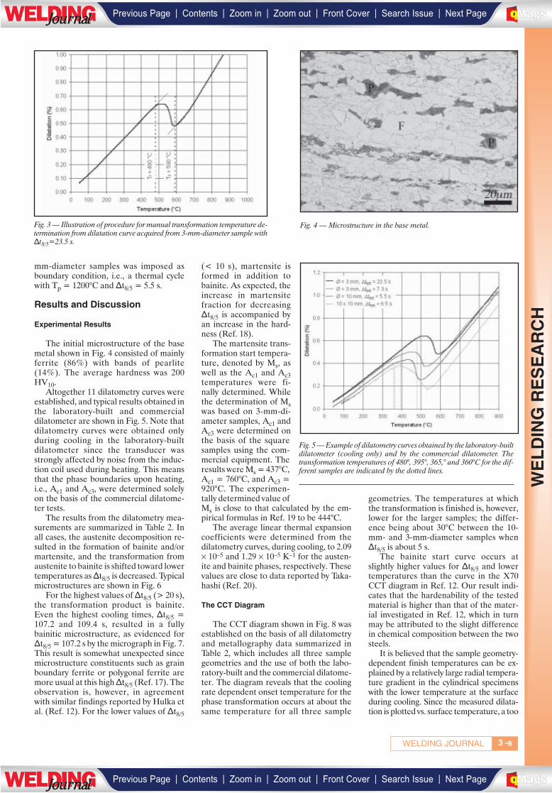
mm-diameter samples was imposed asboundary condition, i.e., a thermal cyclewith Tp = 1200°C and Δt8/5 = 5.5 s.
Results and Discussion
Experimental Results
The initial microstructure of the basemetal shown in Fig. 4 consisted of mainlyferrite (86%) with bands of pearlite(14%). The average hardness was 200HV10.
Altogether 11 dilatometry curves wereestablished, and typical results obtained inthe laboratory-built and commercialdilatometer are shown in Fig. 5. Note thatdilatometry curves were obtained onlyduring cooling in the laboratory-builtdilatometer since the transducer wasstrongly affected by noise from the induc-tion coil used during heating. This meansthat the phase boundaries upon heating,i.e., Ac1 and Ac3, were determined solelyon the basis of the commercial dilatome-ter tests.
The results from the dilatometry mea-surements are summarized in Table 2. Inall cases, the austenite decomposition re-sulted in the formation of bainite and/ormartensite, and the transformation fromaustenite to bainite is shifted toward lowertemperatures as Δt8/5 is decreased. Typicalmicrostructures are shown in Fig. 6
For the highest values of Δt8/5 (> 20 s),the transformation product is bainite.Even the highest cooling times, Δt8/5 =107.2 and 109.4 s, resulted in a fullybainitic microstructure, as evidenced forΔt8/5 = 107.2 s by the micrograph in Fig. 7.This result is somewhat unexpected sincemicrostructure constituents such as grainboundary ferrite or polygonal ferrite aremore usual at this high Δt8/5 (Ref. 17). Theobservation is, however, in agreementwith similar findings reported by Hulka etal. (Ref. 12). For the lower values of Δt8/5
(< 10 s), martensite isformed in addition tobainite. As expected, theincrease in martensitefraction for decreasingΔt8/5 is accompanied byan increase in the hard-ness (Ref. 18).
The martensite trans-formation start tempera-ture, denoted by Ms, aswell as the Ac1 and Ac3temperatures were fi-nally determined. Whilethe determination of Mswas based on 3-mm-di-ameter samples, Ac1 andAc3 were determined onthe basis of the squaresamples using the com-mercial equipment. Theresults were Ms = 437°C,Ac1 = 760°C, and Ac3 =920°C. The experimen-tally determined value ofMs is close to that calculated by the em-pirical formulas in Ref. 19 to be 444°C.
The average linear thermal expansioncoefficients were determined from thedilatometry curves, during cooling, to 2.09× 10⁻⁵ and 1.29 × 10⁻⁵ K–1 for the austen-ite and bainite phases, respectively. Thesevalues are close to data reported by Taka-hashi (Ref. 20).
The CCT Diagram
The CCT diagram shown in Fig. 8 wasestablished on the basis of all dilatometryand metallography data summarized inTable 2, which includes all three samplegeometries and the use of both the labo-ratory-built and the commercial dilatome-ter. The diagram reveals that the coolingrate dependent onset temperature for thephase transformation occurs at about thesame temperature for all three sample
geometries. The temperatures at whichthe transformation is finished is, however,lower for the larger samples; the differ-ence being about 30°C between the 10-mm- and 3-mm-diameter samples whenΔt8/5 is about 5 s.
The bainite start curve occurs atslightly higher values for Δt8/5 and lowertemperatures than the curve in the X70CCT diagram in Ref. 12. Our result indi-cates that the hardenability of the testedmaterial is higher than that of the mater-ial investigated in Ref. 12, which in turnmay be attributed to the slight differencein chemical composition between the twosteels.
It is believed that the sample geometry-dependent finish temperatures can be ex-plained by a relatively large radial tempera-ture gradient in the cylindrical specimenswith the lower temperature at the surfaceduring cooling. Since the measured dilata-tion is plotted vs. surface temperature, a too
WE
LD
ING
RE
SE
AR
CH
3WELDING JOURNAL -s
Fig. 3 — Illustration of procedure for manual transformation temperature de-termination from dilatation curve acquired from 3-mm-diameter sample withΔt8/5=23.5 s.
Fig. 4 — Microstructure in the base metal.
Fig. 5 — Example of dilatometry curves obtained by the laboratory-builtdilatometer (cooling only) and by the commercial dilatometer. Thetransformation temperatures of 480°, 395°, 365,° and 360°C for the dif-ferent samples are indicated by the dotted lines.
| | | | | |Previous Page Contents Zoom in Zoom out Front Cover Search Issue Next PageLWE DINGJournalJournal BA
M SaGEF
| | | | | |Previous Page Contents Zoom in Zoom out Front Cover Search Issue Next PageLWE DINGJournalJournal BA
M SaGEF

low value of the latter compared to the av-erage temperature in the sample would re-sult in an artificially low value for the trans-formation. And the inaccuracy will increasewith sample size and cooling rate due to thecorresponding increase in temperature gra-dient. This assumption is supported by thefindings of Alexandrov et al. (Ref. 21) whosuggested that the temperature gradient in
the sample cross section was a possible rea-son for the delay in the dilatometer re-sponse in experiments comparing single-sensor differential thermal analysis todilatometry.
Relatively large longitudinal tempera-ture gradients exist also in the square sam-ples. Walsh et al. (Ref. 22) examined themagnitude of such gradients as well as the
major factors affecting the gradients in anexperimental setup similar to that used inthe commercial dilatometer in the currentinvestigation. The specimen maximumtemperature of about 1200°C was ob-tained in the mid position between thewater-cooled copper clamps; the clampedends being kept at about 4°C. It is believedthat the lower transformation finish tem-
JANUARY 2009, VOL. 88-s4
WE
LD
ING
RE
SE
AR
CH
Fig. 6 — Microstructure in samples with 3-mm diameter subjected tothermal cycles in the dilatometry tests. A — Tp = 1215°C, Δt8/5 = 1.4s; B — Tp = 1197°C, Δt8/5 = 7.3 s; C — Tp = 1217°C, Δt8/5 = 23.5s.
Table 2 — Results from the Dilatometry Measurements
Sample geometry Tp Δt8/5 Ts Tf Microstructure[°C] [s] [°C] [°C] [vol-%.] Hardness
M B Std. Dev. [HV10]
Diameter 3 mm 1215 1.4 437 295 100 0 0.0 340Diameter 3 mm 1197 7.3 530 395 62 38 3.7 277Diameter 3 mm 1217 23.5 590 480 0 100 0.0 212Diameter 10 mm 1233 5.5 540 365 57 43 4.4 268Diameter 10 mm 1230 9.8 590 410 28 72 5.0 252Diameter 10 mm 1250 21.7 590 480 0 100 0.0 225Diameter 10 mm 1200 107.2 630 490 0 100 0.0 202
Square, 10 × 10 mm 1204 6.5 560 360 66 34 4.5 294Square, 10 × 10 mm 1210 10.2 585 410 46 54 5.1 264Square, 10 × 10 mm 1206 22.6 610 480 0 100 0.0 231Square, 10 × 10 mm 1217 109.4 620 530 0 100 0.0 209
Fig. 7 — Microstructure in a dilatometry sample with 10-mm diametersubjected to a thermal cycle with Tp = 1200°C and Δt8/5 = 107.2 s.
A B
C
| | | | | |Previous Page Contents Zoom in Zoom out Front Cover Search Issue Next PageLWE DINGJournalJournal BA
M SaGEF
| | | | | |Previous Page Contents Zoom in Zoom out Front Cover Search Issue Next PageLWE DINGJournalJournal BA
M SaGEF
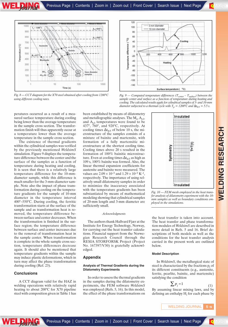
-s5WELDING JOURNAL
peratures occurred as a result of a mea-sured surface temperature during coolingbeing lower than the average temperaturein the sample cross section. The transfor-mation finish will thus apparently occur ata temperature lower than the averagetemperature in the sample cross section.
The existence of thermal gradientswithin the cylindrical samples was verifiedby the previously mentioned WeldsimSsimulation. Figure 9 displays the tempera-ture difference between the center and thesurface of the samples as a function oftemperature during heating and cooling.It is seen that there is a relatively largetemperature difference for the 10-mm-diameter sample, while this difference ismuch smaller for the 3-mm-diameter sam-ple. Note also the impact of phase trans-formation during cooling on the tempera-ture gradients for the sample of 10-mmdiameter in the temperature interval400°–550°C. During cooling, the ferritictransformation starts at the surface of thesample and as transformation heat is re-moved, the temperature difference be-tween surface and center decreases. Whenthe transformation is finished in the sur-face region; the temperature differencebetween surface and center increases dueto the removal of transformation heat inthe sample center. When transformationis complete in the whole sample cross sec-tion, temperature differences decreaseagain. It should also be mentioned thattemperature gradients within the samplemay induce plastic deformations, which inturn may affect the phase transformationduring cooling (Ref. 23).
Conclusions
A CCT diagram valid for the HAZ inwelding operations with relatively rapidheating to about 200°C for X70 pipelinesteel with composition given in Table 1 has
been established by means of dilatometryand metallographic analyses. The Ms, Ac1,and Ac3 temperatures were found to be437°, 760°, and 920°C, respectively. Atcooling times Δt8/5 of below 10 s, the mi-crostructure of the samples consists of amixture of bainite and martensite, withformation of a fully martensitic mi-crostructure at the shortest cooling time.Cooling times above 20 s resulted in theformation of 100% bainitic microstruc-ture. Even at cooling timesΔt8/5 as high as109 s, 100% bainite was formed. Also, thelinear thermal expansion coefficients foraustenite and bainite were measured. Thevalues are 2.09 × 10⁻⁵ and 1.29 × 10⁻⁵ K–1,respectively. The importance of using rel-atively small dilatometry samples in orderto minimize the inaccuracy associatedwith the temperature gradients has beensubstantiated by means of mathematicalmodeling showing that cylindrical samplesof 20-mm length and 3-mm diameter aresufficiently small.
Acknowledgments
The authors thank Hallvard Fjær at theInstitute for Energy Technology, Norway,for carrying out the heat transfer calcula-tions. Financial support from the Norwe-gian Research Council through theRESIA STORFORSK Project (ProjectNo. 167397/V30) is gratefully acknowl-edged.
Appendix
Analysis of Thermal Gradients during theDilatometry Experiments
In order to assess the thermal gradientsin the samples during the dilatometry ex-periments, the FEM software WeldsimSwas employed (Refs. 5, 16). In this model,the effect of the phase transformations on
the heat transfer is taken into account.The heat transfer and phase transforma-tion modules of WeldsimS are described inmore detail in Refs. 5 and 16. Brief de-scriptions of both models as well as theconditions for the heat transfer analysiscarried in the present work are outlinedbelow.
Model Description
In WeldsimS, the metallurgical state ofsteel is characterized by the fractions pi ofits different constituents (e.g., austenite,ferrite, pearlite, bainite, and martensite)satisfying the condition
(1)By assuming linear mixing laws, and bydefining an enthalpy Hi for each phase by
pi∑ = 1
WE
LD
ING
RE
SE
AR
CH
Fig. 8 — CCT diagram for the X70 steel obtained after cooling from 1200°Cusing different cooling rates.
Fig. 9 — Computed temperature differences (Tcenter – Tsurface) between thesample center and surface as a function of temperature during heating andcooling. The calculated results apply for cylindrical samples of 3- and 10-mmdiameter subjected to a thermal cycle with Tp = 1200°C and Δt8/5 = 5.5 s.
Fig. 10 — FEM mesh employed in the heat trans-fer analysis of dilatometry experiment with the 10-mm samples as well as boundary conditions em-ployed in the simulations.
| | | | | |Previous Page Contents Zoom in Zoom out Front Cover Search Issue Next PageLWE DINGJournalJournal BA
M SaGEF
| | | | | |Previous Page Contents Zoom in Zoom out Front Cover Search Issue Next PageLWE DINGJournalJournal BA
M SaGEF
JANUARY 2009, VOL. 88-s6
(2)The equation for the transient heat trans-fer can be written as
(3)where ρi, λi , cp,i, and T denote, respec-tively the density, thermal conductivity,specific heat for phase i, and the tempera-ture. H0
i is the enthalpy of phase i at thereference temperature T0 and Q is the in-ternal heat source. T and pi in Equation3 are derivatives with respect to time. Notethat the second term on the left side ofEquation 3 represents the transformationheat associated with the phase change.
Solving Equation 3 requires the knowl-edge of the phase proportions pi. For thispurpose, the anisothermal transformationkinetics model by Leblond and Devaux(Ref. 24), which has previously been im-plemented in WeldsimS, is employed. Upto five metallurgical phases (austenite,ferrite, pearlite, bainite, and martensite)can be taken into account in WeldsimS. Toillustrate the modeling equations in thecase of two phases (denoted 1 and 2), onehas to distinguish between the 1 → 2 ( p1>0) and the 2 → 1 (p2 > 0) transformations.For each case, the rate of transformationis given by
(4)
(5)
where p1 and p2 denote the fraction ofphase 1 and 2, respectively, with p1 + p2 =1. peq
21 (peq12) is the value of p1 (p2) at
equilibrium for a given temperature, andτ21(τ12 ) is the characteristic time for thetransformation 2 → 1 (1 → 2). The func-tions f21(T), and f12(T) allow for takinginto account the effect of the cooling rate.All these parameters are obtained by fit-ting the phase fractions from various heat-ing/cooling curves to hit correctly theAC1/AC3 (during heating) and thestart/end temperatures for the ferritictransformations shown in CCT diagrams(during cooling).
Application to X70 Steel
To obtain the modeling results of Fig.9, 2-D axis-symmetry models have been
established using cylindrical geometrieswith the same radii and heights as the sam-ples employed in the dilatometry experi-ments (i.e., 5.0 × 20.0 mm2 and 1.5 × 20.0mm2). Figure 10 shows the mesh em-ployed in the thermal analysis as well asthe thermal boundary conditions. Due tosymmetry reason, the computation do-main corresponds to half of the sample.The mesh is made of 300 elements and 338nodes. Thermophysical data in the model-ling were taken from the literature and arethe same as those applied in Ref. 16. Pa-rameters used for the phase transforma-tion model are based on the work of Ref.5 and were extracted using the CCT dia-gram of Hulka et al. (Ref. 12), which is ob-tained for a steel similar to the X70 mate-rial studied in the present work.
As seen in Fig. 10, a time-dependenttemperature is imposed as a thermalboundary condition on the vertical surfaceof the cylinders, while the top and bottomsurfaces are insulated. For both geome-tries, the imposed temperature as a func-tion of time corresponds to the surfacemeasurements for the thermal cycle withTp = 1200°C and Δt8/5 = 5.5 s. For thiscycle, the peak temperature is reachedafter approximately 10 s of heating time.
References
1. Taljat, B., Radhakrishnan, B., andZacharia, T. 1998. Numerical analysis of GTAwelding process with emphasis on post-solidifi-cation phase transformation effects on residualstresses. Materials Science and Engineering A,(246): 45–54.
2. Ferro, P., Porzner, H., Tiziani, A., andBonollo, F. 2006. The influence of phase trans-formations on residual stress induced by thewelding process — 3D and 2D numerical mod-els. Modelling and Simulation in Materials Sci-ence and Engineering, (14): 117–136.
3. Brown, T. B., Dauda, T. A., Truman, C.E., Smith, D. J., Memhard, D., and Pfeiffer, W.2006. Prediction and measurements of residualstress in repair welds in plates. InternationalJournal of Pressure Vessels and Piping, (83):809–818.
4. Deng, D., and Murakawa, H. 2006. Pre-diction of welding residual stress in multi-passbutt-welded modified 9Cr-1Mo steel pipe con-sidering phase transformation effects. Compu-tational Materials Science, (37): 209–219.
5. Aarbogh, H. M., M’Hamdi, M., Mo, A.,and Fjær, H. G. 2007. A simplified method forestablishing constitutive equations and flowstress data for welding stress modelling. Ac-cepted for publication in the Science and Tech-nology of Welding and Joining.
6. Garcia de Andres, C., Caballero, F.,Capdevila, G. C., and Alvarez, L. F. 2002. Ap-plication of dilatometric analysis to the study ofsolid-solid phase transformations in steels. Ma-terials Characterization, (48): 101–111.
7. Reed, R. C., Akbay, T., Shen, Z., Robin-son, J. M., and Root, J. H. 1988. Determinationof reaustenitisation kinetics in a Fe-0.4C steelusing dilatometry and neutron diffraction. Ma-
terials Science and Engineering A, (256):152–165.
8. De Cock, T., Capdevila, C., Caballero, F.G., and Garcia de Andres, C. 2006. Interpreta-tion of a dilatometric anomaly previous to theferrite-to-austenite transformation in a low car-bon steel. Scripta Materialia, (54): 949–954.
9. Leblond, J. B., Mottet, G., and Devaux, J.C. 1986. A theoretical and numerical approachto the plastic behaviour of steels during phasetransformations — I. Derivation of general re-lations. Journal of Mechanical Physics of Solids,(34): 395–409.
10. Zhang, M., Li, L., Fu, R. Y., Krizan, D.,and De Cooman. B. C. 2006. Continuous cool-ing transformation diagrams and properties ofmicro-alloyed TRIP steels. Materials Scienceand Engineering A, (438–440): 296–299.
11. Zhao, M. C., Yang, K., Xiao, F. R., andShan, Y. Y. 2003. Continuous cooling transfor-mation of undeformed and deformed low car-bon pipeline steels. Materials Science and Engi-neering A, (355): 126–136.
12. Hulka, K., Gray, J. M., and Heis-terkamp, F. 1990. Niobium Technical ReportNbTR 16/90, CBMM, Sao Paulo, Brazil.
13. HBM Mess- und Systemtechnik Prüfpro-tokoll Wegaufnehmer. 1998. Ident.-Nr.022440007.
14. API Spec. 5L, Specification for line pipe,Rev. 44, 2007.
15. Onsøien, M. I., Gundersen, Ø., and Ak-selsen, O. M. 1997. Upgrading of Smitweld TCS1405 weld simulator, Sintef report STF24A97401, Trondheim, Norway.
16. Fjær, H. G., Liu, J., M’Hamdi, M., andLindholm. D. 2007. On the use of residualstresses from welding simulations in failure as-sessment analysis for steel structures. H. Cer-jak, H. K. D. H. Bhadeshia, and E. Kozeschnik,editors, Mathematical Modelling of Weld Phe-nomena 8, 96 –979.
17. Kluken, A. O., Onsøien, M. I., Ak-selsen, O. M., and Rørvik, G. 1991. Mechanicalproperties of high heat input deposited weldmetals. Joining Sciences, (1): 14–22.
18. Krauss, G. 1993. Steels: Heat Treatmentand Processing Principles. ASM International,Materials Park, Ohio, 169–177.
19. Andrews, K. W. 1965. Empirical formu-lae for the calculation of some transformationtemperatures. Journal of the Iron and Steel In-stitute, (203): 721–727.
20. Takahashi, M. 1992. Reaustenitizationfrom bainite in steels. PhD thesis, University ofCambridge, Cambridge, UK.
21. Alexandrov, B. T., and Lippold, J. C.2007. Single sensor differential thermal analy-sis of phase transformations and structuralchanges during welding and postweld heattreatment. Welding in the World, 51 (11/12):48–59.
22. Walsh, D. W., Cieslak, M. J., and Savage,W. F. 1986. Temperature measurements in re-sistance heated specimens: Longitudinal gradi-ents. Welding Journal. 65 (7): 184-s to 192-s.
23. Bhadeshia, H. K.D. H. 2004. Develop-ments in martensitic and bainitic steels: role ofthe shape deformation. Materials Science andEngineering A, (378): 34–39.
24. Leblond, L. B., and Devaux, J. 1984. Anew kinetic model for anisothermal metallurgi-cal transformations in steels including effect ofaustenite grain size, Acta Metall, (32): 137–146.
H T H c T dTi i p iT
T( ) = + ( )∫0
0,
ρ ρ
λ
ii
i p i ii
i i
i ii
p c T p H
p T Q
∑ ∑
∑
+ =
∇⋅ ∇⎛
⎝⎜⎜
⎞
⎠⎟⎟+
,� �
� �pp T p
Tf T
e q
212 2
1212
=( )−( )
⎛
⎝
⎜⎜⎜
⎞
⎠
⎟⎟⎟⋅ ( )
τ
1 2→ transformation( )
� �pp T p
Tf T
e q
121 1
2121
=( )−( )
⎛
⎝
⎜⎜⎜
⎞
⎠
⎟⎟⎟⋅ ( )
τ
2 1→ transformation( )
WE
LD
ING
RE
SE
AR
CH
. .
. .
| | | | | |Previous Page Contents Zoom in Zoom out Front Cover Search Issue Next PageLWE DINGJournalJournal BA
M SaGEF
| | | | | |Previous Page Contents Zoom in Zoom out Front Cover Search Issue Next PageLWE DINGJournalJournal BA
M SaGEF
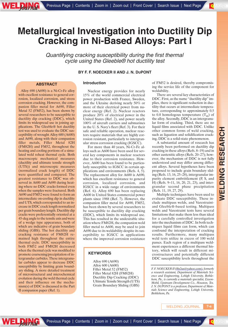
7WELDING JOURNAL
Introduction
Nuclear energy provides for nearly15% of the world commercial electricalpower production with France, Sweden,and the Ukraine deriving nearly 50% ormore of their electrical power from nu-clear energy (Ref. 2). Nuclear reactorsproduce 20% of electrical power in theUnited States (Ref. 2), and power nearly100% of aircraft carriers and submarinesin the U. S. Navy’s fleet (Ref. 3). For theirsafe and reliable operation, nuclear reac-tors require materials that are highly cor-rosion resistant, particularly to intergran-ular stress corrosion cracking (IGSCC).
For more than 40 years, Ni-Cr-Fe al-loys such as A600 have been used for sev-eral key components in nuclear reactorsdue to their corrosion resistance. How-ever, A600 has been found to be particu-larly susceptible to IGSCC in certain ap-plications and environments (Refs. 4, 5).The replacement alloy for A600 is A690,which has excellent resistance to generalcorrosion, localized corrosion, andIGSCC in a wide range of environments(Ref. 6). Alloy 690 has been replacingA600 in United States commercial powerplants since 1988 (Ref. 7). However, thecompanion filler metal for A690, FM52,has been shown by several researchers tobe susceptible to ductility dip cracking(DDC), which limits its widespread use.This has resulted in the undesirable situ-ation where FM82H, the companion weldfiller metal to A600, may be used to joinA690 due to its weldability despite its sus-ceptibility to IGSCC in applicationswhere the improved corrosion resistance
of FM52 is desired, thereby compromis-ing the service life of the component forweldability.
There are several key characteristics ofDDC. First, as the name “ductility dip” im-plies, there is significant reduction in duc-tility that occurs at intermediate tempera-ture, corresponding to approximately 0.5to 0.8 homologous temperature (Tm) ofthe alloy. Secondly, DDC is an intergranu-lar form of cracking. Third, there are noliquid films associated with DDC. Unlikeother common forms of weld cracking,such as liquation and solidification crack-ing, DDC is a solid-state phenomenon.
A substantial amount of research hasrecently been performed on ductility dipcracking in these alloys (Refs. 8–19) and inother austenitic alloys (Refs. 20–27); how-ever, the mechanism of DDC is not fullyunderstood and may differ among differ-ent alloys. Several hypotheses have beenproposed to include grain boundary slid-ing (Refs. 13, 16, 25–28), intergranular im-purity element embrittlement (P, S, andH) (Refs. 9–11, 16, 20, 21, 23), and inter-granular second phase precipitation(Refs. 11, 19, 27, 29).
Multiple techniques have been used toevaluate DDC susceptibility. These in-clude multipass welds, and Varestraint-and Gleeble®-based testing. Multipasswelds and Varestraint tests have severallimitations that make them less than idealfor a carefully controlled investigationinto the mechanism of DDC. In both tech-niques liquid films can form, which canconfound the interpretation of crackingresults. Furthermore, many multipassweld tests utilize in excess of 100 weldpasses. Each region of a multipass weld-ment experiences a different thermal his-tory, which will result in different mi-crostructures and potentially differentDDC susceptibility levels throughout the
KEYWORDS
Alloy 690 (A690)Alloy 600 (A600)Filler Metal 52 (FM52)Filler Metal 82H (FM82H)Ductility Dip Cracking (DDC)Ultimate Tensile Strength (UTS)Grain Boundary Sliding (GBS)
F. F. NOECKER II ([email protected]), formerlya research assistant, Department of Materials Sci-ence and Engineering, Lehigh University, Bethle-hem, Pa., is currently a materials specialist, Exxon-Mobil, Upstream Development Co., Houston, Tex.J. N. DUPONT is a professor, Department of Mate-rials Science and Engineering, Lehigh University,Bethlehem, Pa.
Metallurgical Investigation into Ductility DipCracking in Ni-Based Alloys: Part I
Quantifying cracking susceptibility during the first thermal cycle using the Gleeble® hot ductility test
BY F. F. NOECKER II AND J. N. DUPONT
-s
ABSTRACT
Alloy 690 (A690) is a Ni-Cr-Fe alloywith excellent resistance to general cor-rosion, localized corrosion, and stresscorrosion cracking. However, the com-panion filler metal for A690, FillerMetal 52 (FM52), has been shown byseveral researchers to be susceptible toductility dip cracking (DDC), whichlimits its widespread use in joining ap-plications. The Gleeble® hot ductilitytest was used to evaluate the DDC sus-ceptibility of wrought Alloy 600 (A600)and A690, along with their companionfiller metals, Filler Metal 82H(FM82H) and FM52, throughout theheating and cooling portions of a simu-lated weld reheat thermal cycle. Bothmacroscopic mechanical measures(ductility and ultimate tensile strength(UTS)) and microscopic measures(normalized crack length) of DDCwere quantified and compared. Thegreatest resistance to DDC was ob-served in A600 and A690 during heat-ing where no DDC cracks formed evenwhen the samples were fractured. BothA690 and FM52 were found to form anintermediate on-cooling dip in ductilityand UTS, which corresponded to an in-crease in DDC crack length normalizedper grain boundary length. Ductility dipcracks were preferentially oriented at a45-deg angle to the tensile axis and wereof a wedge type appearance, both ofwhich are indicative of grain boundarysliding (GBS). The hot ductility andcracking resistance of FM82H re-mained high throughout the entirethermal cycle. DDC susceptibility inboth FM52 and FM82H decreasedwhen the thermal cycle was modified topromote coarsening/precipitation of in-tergranular carbides. These intergranu-lar carbides appear to decrease DDCsusceptibility by limiting grain bound-ary sliding. A more detailed treatmentof microstructural and microchemicalevolution during the weld thermal cycleand their influence on the mecha-nism(s) of DDC is discussed in the PartII companion paper (Ref. 1).
WE
LD
ING
RE
SE
AR
CH
___________
| | | | | |Previous Page Contents Zoom in Zoom out Front Cover Search Issue Next PageLWE DINGJournalJournal BA
M SaGEF
| | | | | |Previous Page Contents Zoom in Zoom out Front Cover Search Issue Next PageLWE DINGJournalJournal BA
M SaGEF
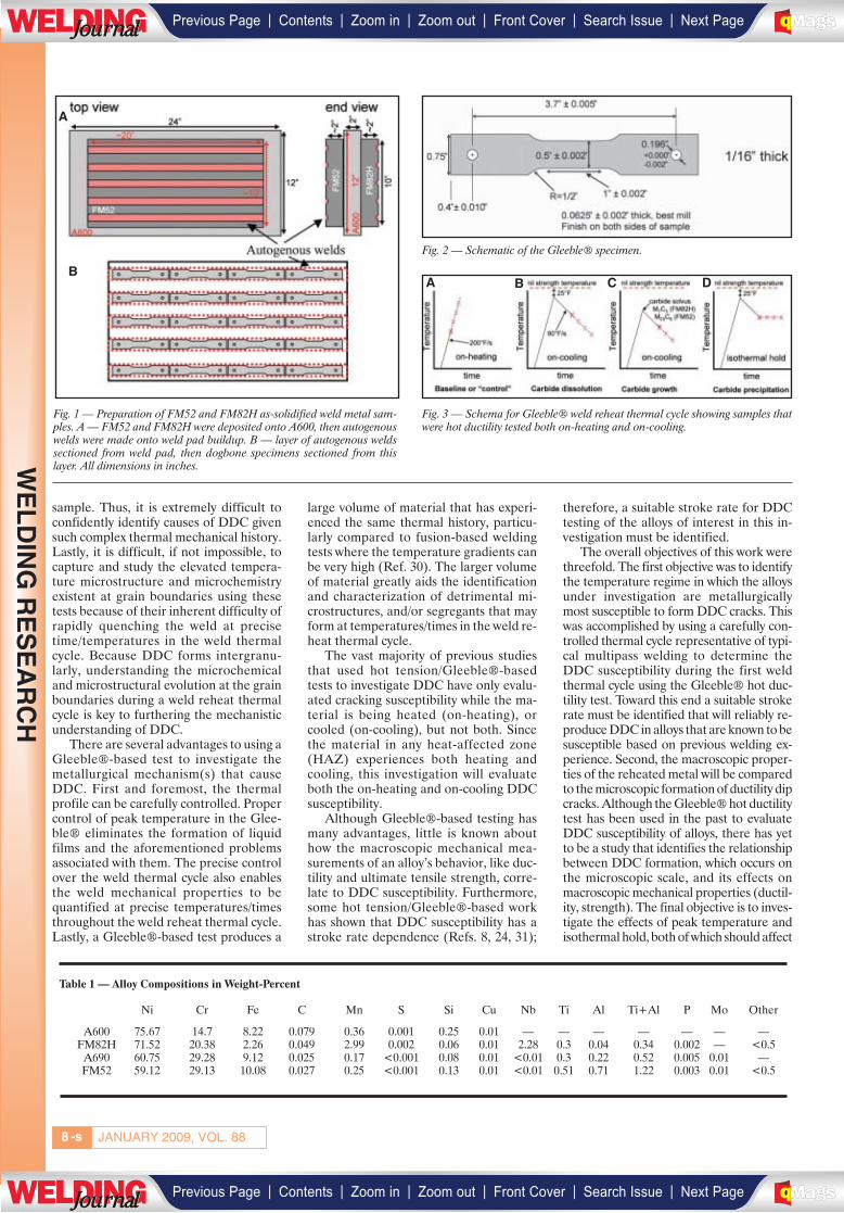
JANUARY 2009, VOL. 88-s8
sample. Thus, it is extremely difficult toconfidently identify causes of DDC givensuch complex thermal mechanical history.Lastly, it is difficult, if not impossible, tocapture and study the elevated tempera-ture microstructure and microchemistryexistent at grain boundaries using thesetests because of their inherent difficulty ofrapidly quenching the weld at precisetime/temperatures in the weld thermalcycle. Because DDC forms intergranu-larly, understanding the microchemicaland microstructural evolution at the grainboundaries during a weld reheat thermalcycle is key to furthering the mechanisticunderstanding of DDC.
There are several advantages to using aGleeble®-based test to investigate themetallurgical mechanism(s) that causeDDC. First and foremost, the thermalprofile can be carefully controlled. Propercontrol of peak temperature in the Glee-ble® eliminates the formation of liquidfilms and the aforementioned problemsassociated with them. The precise controlover the weld thermal cycle also enablesthe weld mechanical properties to bequantified at precise temperatures/timesthroughout the weld reheat thermal cycle.Lastly, a Gleeble®-based test produces a
large volume of material that has experi-enced the same thermal history, particu-larly compared to fusion-based weldingtests where the temperature gradients canbe very high (Ref. 30). The larger volumeof material greatly aids the identificationand characterization of detrimental mi-crostructures, and/or segregants that mayform at temperatures/times in the weld re-heat thermal cycle.
The vast majority of previous studiesthat used hot tension/Gleeble®-basedtests to investigate DDC have only evalu-ated cracking susceptibility while the ma-terial is being heated (on-heating), orcooled (on-cooling), but not both. Sincethe material in any heat-affected zone(HAZ) experiences both heating andcooling, this investigation will evaluateboth the on-heating and on-cooling DDCsusceptibility.
Although Gleeble®-based testing hasmany advantages, little is known abouthow the macroscopic mechanical mea-surements of an alloy’s behavior, like duc-tility and ultimate tensile strength, corre-late to DDC susceptibility. Furthermore,some hot tension/Gleeble®-based workhas shown that DDC susceptibility has astroke rate dependence (Refs. 8, 24, 31);
therefore, a suitable stroke rate for DDCtesting of the alloys of interest in this in-vestigation must be identified.
The overall objectives of this work werethreefold. The first objective was to identifythe temperature regime in which the alloysunder investigation are metallurgicallymost susceptible to form DDC cracks. Thiswas accomplished by using a carefully con-trolled thermal cycle representative of typi-cal multipass welding to determine theDDC susceptibility during the first weldthermal cycle using the Gleeble® hot duc-tility test. Toward this end a suitable strokerate must be identified that will reliably re-produce DDC in alloys that are known to besusceptible based on previous welding ex-perience. Second, the macroscopic proper-ties of the reheated metal will be comparedto the microscopic formation of ductility dipcracks. Although the Gleeble® hot ductilitytest has been used in the past to evaluateDDC susceptibility of alloys, there has yetto be a study that identifies the relationshipbetween DDC formation, which occurs onthe microscopic scale, and its effects onmacroscopic mechanical properties (ductil-ity, strength). The final objective is to inves-tigate the effects of peak temperature andisothermal hold, both of which should affect
Fig. 2 — Schematic of the Gleeble® specimen.
Fig. 1 — Preparation of FM52 and FM82H as-solidified weld metal sam-ples. A — FM52 and FM82H were deposited onto A600, then autogenouswelds were made onto weld pad buildup. B — layer of autogenous weldssectioned from weld pad, then dogbone specimens sectioned from thislayer. All dimensions in inches.
Fig. 3 — Schema for Gleeble® weld reheat thermal cycle showing samples thatwere hot ductility tested both on-heating and on-cooling.
Table 1 — Alloy Compositions in Weight-Percent
Ni Cr Fe C Mn S Si Cu Nb Ti Al Ti+Al P Mo Other
A600 75.67 14.7 8.22 0.079 0.36 0.001 0.25 0.01 — — — — — — —FM82H 71.52 20.38 2.26 0.049 2.99 0.002 0.06 0.01 2.28 0.3 0.04 0.34 0.002 — <0.5
A690 60.75 29.28 9.12 0.025 0.17 <0.001 0.08 0.01 <0.01 0.3 0.22 0.52 0.005 0.01 —FM52 59.12 29.13 10.08 0.027 0.25 <0.001 0.13 0.01 <0.01 0.51 0.71 1.22 0.003 0.01 <0.5
A
BA B C D
WE
LD
ING
RE
SE
AR
CH
| | | | | |Previous Page Contents Zoom in Zoom out Front Cover Search Issue Next PageLWE DINGJournalJournal BA
M SaGEF
| | | | | |Previous Page Contents Zoom in Zoom out Front Cover Search Issue Next PageLWE DINGJournalJournal BA
M SaGEF
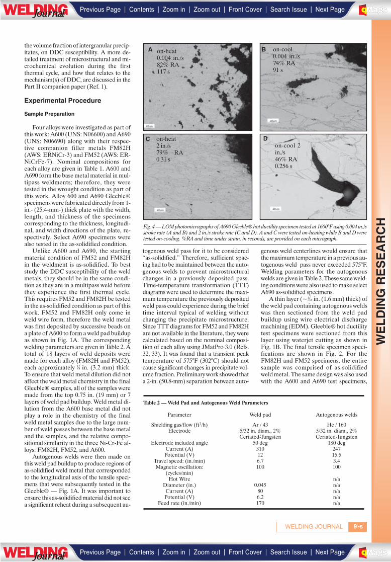
the volume fraction of intergranular precip-itates, on DDC susceptibility. A more de-tailed treatment of microstructural and mi-crochemical evolution during the firstthermal cycle, and how that relates to themechanism(s) of DDC, are discussed in thePart II companion paper (Ref. 1).
Experimental Procedure
Sample Preparation
Four alloys were investigated as part ofthis work: A600 (UNS: N06600) and A690(UNS: N06690) along with their respec-tive companion filler metals FM82H(AWS: ERNiCr-3) and FM52 (AWS: ER-NiCrFe-7). Nominal compositions foreach alloy are given in Table 1. A600 andA690 form the base metal material in mul-tipass weldments; therefore, they weretested in the wrought condition as part ofthis work. Alloy 600 and A690 Gleeble®specimens were fabricated directly from 1-in.- (25.4-mm-) thick plate with the width,length, and thickness of the specimenscorresponding to the thickness, longitudi-nal, and width directions of the plate, re-spectively. Select A690 specimens werealso tested in the as-solidified condition.
Unlike A600 and A690, the startingmaterial condition of FM52 and FM82Hin the weldment is as-solidified. To beststudy the DDC susceptibility of the weldmetals, they should be in the same condi-tion as they are in a multipass weld beforethey experience the first thermal cycle.This requires FM52 and FM82H be testedin the as-solidified condition as part of thiswork. FM52 and FM82H only come inweld wire form, therefore the weld metalwas first deposited by successive beads ona plate of A600 to form a weld pad buildupas shown in Fig. 1A. The correspondingwelding parameters are given in Table 2. Atotal of 18 layers of weld deposits weremade for each alloy (FM82H and FM52),each approximately 1⁄8 in. (3.2 mm) thick.To ensure that weld metal dilution did notaffect the weld metal chemistry in the finalGleeble® samples, all of the samples weremade from the top 0.75 in. (19 mm) or 7layers of weld pad buildup. Weld metal di-lution from the A600 base metal did notplay a role in the chemistry of the finalweld metal samples due to the large num-ber of weld passes between the base metaland the samples, and the relative compo-sitional similarity in the three Ni-Cr-Fe al-loys: FM82H, FM52, and A600.
Autogenous welds were then made onthis weld pad buildup to produce regions ofas-solidified weld metal that correspondedto the longitudinal axis of the tensile speci-mens that were subsequently tested in theGleeble® — Fig. 1A. It was important toensure this as-solidified material did not seea significant reheat during a subsequent au-
togenous weld pass for it to be considered“as-solidified.” Therefore, sufficient spac-ing had to be maintained between the auto-genous welds to prevent microstructuralchanges in a previously deposited pass.Time-temperature transformation (TTT)diagrams were used to determine the maxi-mum temperature the previously depositedweld pass could experience during the brieftime interval typical of welding withoutchanging the precipitate microstructure.Since TTT diagrams for FM52 and FM82Hare not available in the literature, they werecalculated based on the nominal composi-tion of each alloy using JMatPro 3.0 (Refs.32, 33). It was found that a transient peaktemperature of 575°F (302°C) should notcause significant changes in precipitate vol-ume fraction. Preliminary work showed thata 2-in. (50.8-mm) separation between auto-
genous weld centerlines would ensure thatthe maximum temperature in a previous au-togenous weld pass never exceeded 575°F.Welding parameters for the autogenouswelds are given in Table 2. These same weld-ing conditions were also used to make selectA690 as-solidified specimens.
A thin layer (~1⁄16 in. (1.6 mm) thick) ofthe weld pad containing autogenous weldswas then sectioned from the weld padbuildup using wire electrical dischargemachining (EDM). Gleeble® hot ductilitytest specimens were sectioned from thislayer using waterjet cutting as shown inFig. 1B. The final tensile specimen speci-fications are shown in Fig. 2. For theFM82H and FM52 specimens, the entiresample was comprised of as-solidifiedweld metal. The same design was also usedwith the A600 and A690 test specimens,
9WELDING JOURNAL -s
Fig. 4 — LOM photomicrographs of A690 Gleeble® hot ductility specimen tested at 1600°F using 0.004 in./sstroke rate (A and B) and 2 in./s stroke rate (C and D). A and C were tested on-heating while B and D weretested on-cooling. %RA and time under strain, in seconds, are provided on each micrograph.
Table 2 — Weld Pad and Autogenous Weld Parameters
Parameter Weld pad Autogenous welds
Shielding gas/flow (ft3/h) Ar / 43 He / 160Electrode 5/32 in. diam., 2% 5/32 in. diam., 2%
Ceriated-Tungsten Ceriated-TungstenElectrode included angle 50 deg 180 deg
Current (A) 310 247Potential (V) 12 15.5
Travel speed: (in./min) 6.7 3.4Magnetic oscillation: 100 100
(cycles/min)Hot Wire n/a
Diameter (in.) 0.045 n/aCurrent (A) 80 n/aPotential (V) 6.2 n/a
Feed rate (in./min) 170 n/a
A on-heat0.004 in./s82% RA117 s
on-cool0.004 in./s74% RA91 s
on-cool 2in./s46% RA0.256 s
on-heat2 in./s 79% RA0.31 s
B
C D
WE
LD
ING
RE
SE
AR
CH
| | | | | |Previous Page Contents Zoom in Zoom out Front Cover Search Issue Next PageLWE DINGJournalJournal BA
M SaGEF
| | | | | |Previous Page Contents Zoom in Zoom out Front Cover Search Issue Next PageLWE DINGJournalJournal BA
M SaGEF
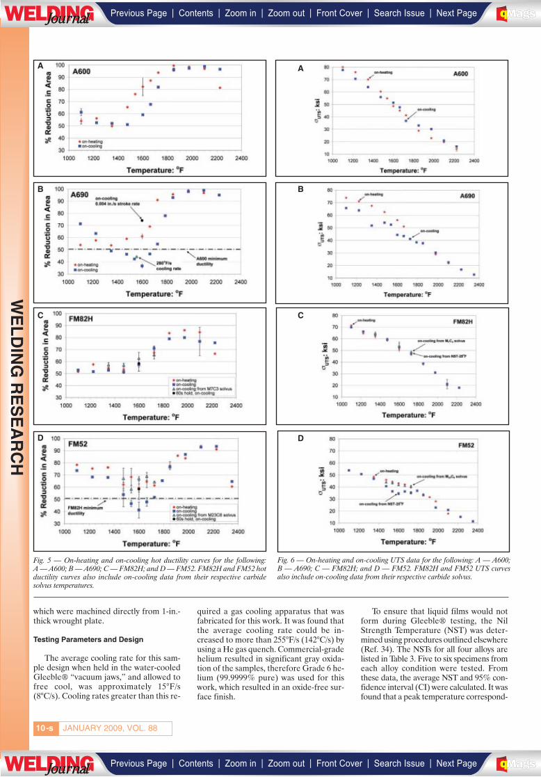
JANUARY 2009, VOL. 88-s10
which were machined directly from 1-in.-thick wrought plate.
Testing Parameters and Design
The average cooling rate for this sam-ple design when held in the water-cooledGleeble® “vacuum jaws,” and allowed tofree cool, was approximately 15°F/s(8°C/s). Cooling rates greater than this re-
quired a gas cooling apparatus that wasfabricated for this work. It was found thatthe average cooling rate could be in-creased to more than 255°F/s (142°C/s) byusing a He gas quench. Commercial-gradehelium resulted in significant gray oxida-tion of the samples, therefore Grade 6 he-lium (99.9999% pure) was used for thiswork, which resulted in an oxide-free sur-face finish.
To ensure that liquid films would notform during Gleeble® testing, the NilStrength Temperature (NST) was deter-mined using procedures outlined elsewhere(Ref. 34). The NSTs for all four alloys arelisted in Table 3. Five to six specimens fromeach alloy condition were tested. Fromthese data, the average NST and 95% con-fidence interval (CI) were calculated. It wasfound that a peak temperature correspond-
Fig. 5 — On-heating and on-cooling hot ductility curves for the following:A — A600; B — A690; C — FM82H; and D — FM52. FM82H and FM52 hotductility curves also include on-cooling data from their respective carbidesolvus temperatures.
Fig. 6 — On-heating and on-cooling UTS data for the following: A — A600;B — A690; C — FM82H; and D — FM52. FM82H and FM52 UTS curvesalso include on-cooling data from their respective carbide solvus.
A
B
C C
D D
A
B
WE
LD
ING
RE
SE
AR
CH
| | | | | |Previous Page Contents Zoom in Zoom out Front Cover Search Issue Next PageLWE DINGJournalJournal BA
M SaGEF
| | | | | |Previous Page Contents Zoom in Zoom out Front Cover Search Issue Next PageLWE DINGJournalJournal BA
M SaGEF
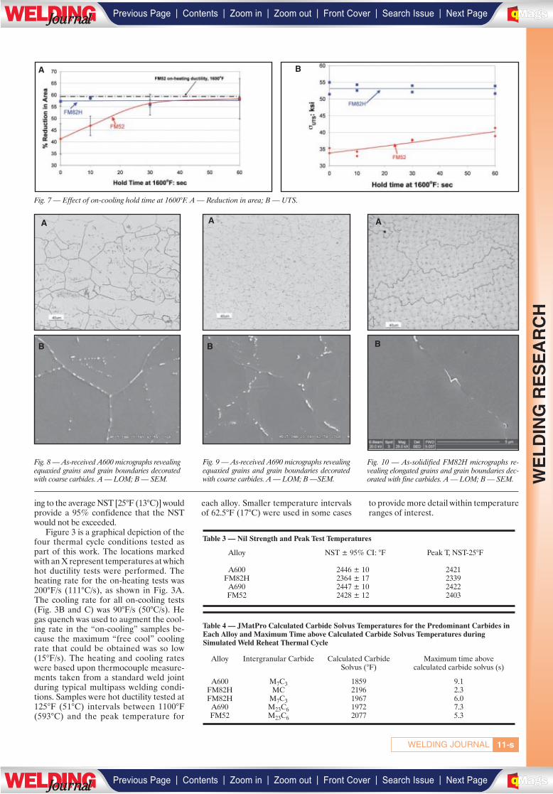
-s11WELDING JOURNAL
ing to the average NST [25°F (13°C)] wouldprovide a 95% confidence that the NSTwould not be exceeded.
Figure 3 is a graphical depiction of thefour thermal cycle conditions tested aspart of this work. The locations markedwith an X represent temperatures at whichhot ductility tests were performed. Theheating rate for the on-heating tests was200°F/s (111°C/s), as shown in Fig. 3A.The cooling rate for all on-cooling tests(Fig. 3B and C) was 90°F/s (50°C/s). Hegas quench was used to augment the cool-ing rate in the “on-cooling” samples be-cause the maximum “free cool” coolingrate that could be obtained was so low(15°F/s). The heating and cooling rateswere based upon thermocouple measure-ments taken from a standard weld jointduring typical multipass welding condi-tions. Samples were hot ductility tested at125°F (51°C) intervals between 1100°F(593°C) and the peak temperature for
each alloy. Smaller temperature intervalsof 62.5°F (17°C) were used in some cases
to provide more detail within temperatureranges of interest.
Table 3 — Nil Strength and Peak Test Temperatures
Alloy NST ± 95% CI: °F Peak T, NST-25°F
A600 2446 ± 10 2421FM82H 2364 ± 17 2339
A690 2447 ± 10 2422FM52 2428 ± 12 2403
Table 4 — JMatPro Calculated Carbide Solvus Temperatures for the Predominant Carbides inEach Alloy and Maximum Time above Calculated Carbide Solvus Temperatures during Simulated Weld Reheat Thermal Cycle
Alloy Intergranular Carbide Calculated Carbide Maximum time above Solvus (°F) calculated carbide solvus (s)
A600 M7C3 1859 9.1FM82H MC 2196 2.3FM82H M7C3 1967 6.0
A690 M23C6 1972 7.3FM52 M23C6 2077 5.3
Fig. 7 — Effect of on-cooling hold time at 1600°F. A — Reduction in area; B — UTS.
Fig. 8 — As-received A600 micrographs revealingequaxied grains and grain boundaries decoratedwith coarse carbides. A — LOM; B — SEM.
Fig. 9 — As-received A690 micrographs revealingequaxied grains and grain boundaries decoratedwith coarse carbides. A — LOM; B —SEM.
Fig. 10 — As-solidified FM82H micrographs re-vealing elongated grains and grain boundaries dec-orated with fine carbides. A — LOM; B — SEM.
A B
B
A A A
B B
WE
LD
ING
RE
SE
AR
CH
| | | | | |Previous Page Contents Zoom in Zoom out Front Cover Search Issue Next PageLWE DINGJournalJournal BA
M SaGEF
| | | | | |Previous Page Contents Zoom in Zoom out Front Cover Search Issue Next PageLWE DINGJournalJournal BA
M SaGEF
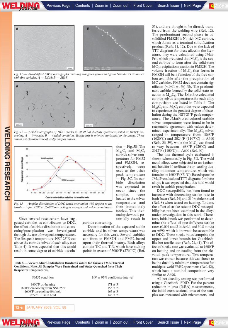
-s12
Since several researchers have sug-gested carbides as contributors to DDC,the effect of carbide dissolution and coars-ening/precipitation was investigatedthrough the use of two peak temperatures.The first peak temperature, NST-25°F, wasabove the carbide solvus of each alloy (seeTable 4). It was expected that this wouldresult in some degree of carbide dissolu-
tion — Fig. 3B. TheM23C6 and M7C3carbide solvus tem-perature for FM52and FM82H, re-spectively, wereused as the otherpeak temperature— Fig. 3C. No car-bide dissolutionwas expected tooccur since thesamples wereheated to the solvustemperature andthen immediatelycooled. This ther-mal cycle would po-tentially result in
carbide coarsening.Determination of the expected stable
carbide and its solvus temperature wasnecessary for this work. Several carbidescan form in FM82H and FM52 basedupon their thermal history. Both alloyscontain TiC and TiN, which have meltingpoints in excess of 5000°F (2760°C) (Ref.
35), and are thought to be directly trans-ferred from the welding wire (Ref. 12).The predominant second phase in as-solidified FM82H is Nb-rich MC carbide,which forms as a terminal solidificationproduct (Refs. 11, 12). Due to the lack ofTTT diagrams for these alloys in the liter-ature, they were calculated using JMat-Pro, which predicted that M7C3 is the sec-ond carbide to form after the solid-stateMC precipitation reaction in FM82H. Thevolume fraction of M7C3 that forms inFM82H will be a function of the free car-bon available after the precipitation ofMC carbides. FM52 does not contain sig-nificant (<0.01 wt-%) Nb. The predomi-nant carbide formed by the solid-state re-action is M23C6. The JMatPro calculatedcarbide solvus temperatures for each alloycomposition are listed in Table 4. TheM23C6 and M7C3 carbides were expectedto experience the greatest degree of disso-lution during the NST-25°F peak temper-ature. The JMatPro calculated carbidesolvus temperatures were found to be inreasonable agreement with values deter-mined experimentally: The M23C6 solvusranged in temperature from 1868°F(1020°C) and 2024°F (1107°C) in A690(Refs. 36–39), while the M7C3 was foundto vary between 1688°F (920°C) and2012°F (1100°C) in A600 (Ref. 40).
The last thermal cycle evaluated isshown schematically in Fig. 3D. The weldmetal alloys were subjected to an isother-mal hold for 10 to 60 s at the on-cooling duc-tility minimum temperature, which wasfound to be 1600°F (871°C). Based upon theJMatPro calculated TTT diagrams for thesealloys, it was expected that this hold wouldresult in carbide precipitation.
DDC susceptibility has been found toincrease with decreasing stroke rate inboth Invar (Ref. 24) and 310 stainless steel(Ref. 8) when tested on-heating. To date,the effect of stroke rate on DDC suscepti-bility has not been examined in the alloysunder investigation in this work. There-fore, initial work was performed to deter-mine the effect of two different strokerates (0.004 and 2 in./s: 0.1 and 50.8 mm/s)on A690, which is known to be susceptibleto DDC. These stroke rates comprise theupper and lower bounds for Gleeble®-like hot tensile tests (Refs. 24, 41). The ef-fect of stroke rate was evaluated at 1600°Fon-heating and on-cooling from the ele-vated peak temperature. This tempera-ture was chosen because this was shown tobe the ductility minimum temperature formultipass weld FM52 specimens (Ref. 42),which have a nominal composition verysimilar to A690.
All hot ductility testing was performedusing a Gleeble® 1500D. For the percentreduction in area (%RA) measurements,the initial cross-sectional area of the sam-ples was measured with micrometers, and
Table 5 — Vickers Micro-Indentation Hardness Values for Various FM52 Thermal Conditions. Note: All Samples Were Unstrained and Water Quenched from Their Respective Temperatures
FM52 condition HV ± 95% confidence interval
1600°F on-heating 171 ± 31600°F on-cooling from NST-25°F 155 ± 2
1600°F on-cooling 60 s hold 165 ± 32350°F 10 min hold 146 ± 2
Fig. 11 — As-solidified FM52 micrographs revealing elongated grains and grain boundaries decoratedwith fine carbides. A — LOM; B — SEM.
Fig. 12 — LOM micrographs of DDC cracks in A690 hot ductility specimens tested at 1600°F on-cooling. A — Wrought; B — welded condition. Tensile axis is oriented horizontal to the image. Thesecracks are characteristic of wedge shaped cracks.
Fig. 13 — Angular distribution of DDC crack orientation with respect to thetensile axis for A690 at 1600°F on-cooling in wrought and welded conditions.
JANUARY 2009, VOL. 88
A B
A B
WE
LD
ING
RE
SE
AR
CH
| | | | | |Previous Page Contents Zoom in Zoom out Front Cover Search Issue Next PageLWE DINGJournalJournal BA
M SaGEF
| | | | | |Previous Page Contents Zoom in Zoom out Front Cover Search Issue Next PageLWE DINGJournalJournal BA
M SaGEF

the final cross-sectional area was measuredusing a stereoscope connected to quantita-tive image analysis software, in a similarfashion as used in other research (Ref. 18).This provided for a more accurate mea-surement of %RA, particularly in sampleswhere the final cross-sectional shape wasnot rectangular. Two measurements weremade of each fractured surface, resulting infour measurements per tested specimen.The %RA measurement error was found tofall within the size of the data symbols in thehot ductility plots. When multiple sampleswere tested under the same conditions, theaverage was plotted with standard deviationerror bars. The ultimate tensile strength(UTS) was calculated for each alloy basedupon load measurements recorded fromGleeble® load cell data. An acquisition rateof 2000 hertz was used during the loadingportion of the test to ensure the peak loadcould be identified.
Microstructural and MicromechanicalCharacterization
Select samples were sectioned andmounted in thermosetting epoxy so that thelongitudinal-transverse orientation of eachtest specimen could be viewed. Standardmetallographic techniques were used toprepare the samples to a 0.05-μm colloidalsilica finish. The samples were then elec-trolytically etched at 2–3 V for 3–10 s in asolution containing equal parts by volumeof water, and sulfuric and phosphoric acid.Bright field light optical microscope (LOM)
images were captured using aReichert-Jung MF3 metallograph. The an-gular relationship between grain bound-aries that ductility dip cracked and the ten-sile axis were made using LOM images.
Ductility dip crack length measure-ments were made using a Nikon OptiphotLOM with a drawing tube attachment thatallowed for concurrent viewing of the sam-ple and the cursor of a digitizing pad.Crack length data were normalized withrespect to total grain boundary lengthwithin a field of measurement so that thecracking behavior of different alloys atvarious temperatures can be compared onan equal basis. The total grain boundarylength within a field of measurement is afunction of 1) the surface area of the sam-ple from which crack length was measuredand 2) the grain size of the sample. This
normalization was conducted in the fol-lowing manner. The total grain boundarylength within a unit surface area is givenby L Total/GB (Ref. 43):
where NL is the number of intersectionsper unit length of line with units of mm–1,and SA is the surface area in mm2. Thisvalue of NL can be calculated directly fromgrain size using the following equationthat is derived from ASTM E112 (Ref.44):
where grain size (d) is measured in μm.Grain size data were measured for thesealloys at select temperatures in the weld
N dL = −1119 3 20 9993. ( ).
L N SAGBTotal
L= ⎛⎝⎜
⎞⎠⎟ ⋅
π2
1( )
Fig. 14 — Total intergranular crack length per grain boundary length. A — A600; B — A690; C — FM82H; and D — FM52.
Fig. 15 — LOM images of A690 hot ductility samples revealing dynamically recrystallized grains. A —1850°F on-heating; and B — 1850°F on-cooling.
-s13WELDING JOURNAL
A B
A B
C D
A690 1850°F on-heating A690 1850°F on-cooling
WE
LD
ING
RE
SE
AR
CH
| | | | | |Previous Page Contents Zoom in Zoom out Front Cover Search Issue Next PageLWE DINGJournalJournal BA
M SaGEF
| | | | | |Previous Page Contents Zoom in Zoom out Front Cover Search Issue Next PageLWE DINGJournalJournal BA
M SaGEF

thermal cycle using water-quenched spec-imens. Equation 1 can be combined withEquation 2 to result in the following:
The total measured DDC crack lengthwithin any given sample was divided by thetotal grain boundary length within thefield of measurement (L ) to provide theaverage crack length per length of grainboundary (μm/mm).
The general microstructure and chem-istry of second phases were characterizedusing either an FEI DB 235 or Hitachi4300 Schottky field emission gun scanningelectron microscope (FEG-SEM) with anenergy-dispersive spectrometer (EDS).All operation was performed using 20 keVaccelerating voltage. An Everhart-Thorn-ley detector, commonly known as a sec-ondary electron detector (SED), was usedfor all SEM images. The scale markers dif-fer for the two microscopes. Images cap-tured using the Hitachi 4300 use a 10 dotmarker with the scale indicated on thelower-right corner of the image. Samplesmounted in epoxy were lightly coated withcarbon to prevent charging. The aboveconditions enabled particles as small as 20nm in size to be resolved.
Lastly, to determine whether the ther-mal history had an annealing effect onFM52, 20 Vickers micro-indentation
hardness measurements were made oneach of four select samples according toASTM E384 (Ref. 45). All of the speci-mens were water quenched and un-strained (Ref. 1). The four thermal histo-ries evaluated were 1) 1600°F on-heating,2) 1600°F on-cooling from the NST-25°Ftemperature, 3) 60-s hold at 1600°F on-cooling from the NST-25°F temperature,and 4) 10-min hold at 2350°F (1288°C).The heating and cooling rate (for on-cool-ing samples) was the same as used above:200°F/s (111°C/s) on-heating and 90°F/s(50°C/s) on-cooling.
Results
Effect of Stroke Rate
Representative microstructures for theslow stroke rate and fast stroke rate testsperformed at 1600°F on-heating and on-cooling are shown in Fig. 4. There was lit-tle difference between on-heating and on-cooling ductility for the slow stroke ratesamples, which was 82% and 74%RA, re-spectively. Conversely, the fast stroke rateon-cooling test resulted in a significantductility loss as compared to the on-heat-ing test using the same stroke rate: 46% vs.79%RA, respectively. Although 46% is anappreciable degree of ductility, what is sig-nificant is that the ductility decreased 42%as compared to the on-heating test.
Microstructurally, this intermediate
temperature on-cooling reduction in duc-tility was caused by a large number of duc-tility dip cracks — Fig. 4D, which were notpresent in the on-heating sample tested atthe same stroke rate — Fig. 4C. Both on-heating samples exhibited intergranularcavitation with transgranular void coales-cence occurring in the slower stroke ratesample — Fig. 4A. The slower stroke rate,on-cooling sample did have some ductilitydip cracks, but they were surrounded byrecrystallized grains. The ductility dipcracking was much more severe in the faststroke rate on-cooling sample. The totalnormalized DDC crack count in the faststroke rate on-cooling sample was 23.0μm/mm while that for the slow stroke rateon-cooling sample was only 1.7 μm/mm.
These results are significant for severalreasons. This is the first investigation intothe effect of stroke rate on hot ductility ina Ni-based, solid-solution-strengthenedNi-Cr-Fe alloy. Second, previous re-searchers showed that slower stroke ratesincreased DDC in 310 stainless steel (0.1vs. 100 mm/s) (Ref. 8) and Invar (0.094 vs.13 mm/s) (Ref. 24); however, this work re-veals just the opposite effect for the alloysinvestigated in this work where fasterstroke rates result in more DDC. Thecauses for these differences in stroke rateand hot ductility behavior are discussedlater. Lastly, the faster stroke rate resultedin a more adverse testing condition forDDC, while reproducing the DDC mech-
L d SAGBTotal = ( ) ⋅−π
21119 3 30 993. ( ).
Fig. 16 — Ductility dip crack in FM52 at 2100°F on-cooling as seen using the follow-ing: A — Differential image contrast in LOM; B — SEM at low magnification; and C— SEM at high magnification. Recrystallization along grain boundary impedes duc-tility dip crack growth.
Fig. 17 — Schematic showing how orientation of grain boundaryplane with the tensile direction (45 deg) can be different than thegrain boundary line with the tensile direction (90 deg).
Fig. 18 — Influence of starting grain size on dynamic recrystallizationbehavior from Ref. 64. A–D show the development of completely re-crystallized grain structure when the grain size is large compared to therecrystallized grain size. In E, the initial and recrystallized grains havesimilar sizes.
-s14 JANUARY 2009, VOL. 88
C
A
B
C
D E
A B
TotalGB
WE
LD
ING
RE
SE
AR
CH
| | | | | |Previous Page Contents Zoom in Zoom out Front Cover Search Issue Next PageLWE DINGJournalJournal BA
M SaGEF
| | | | | |Previous Page Contents Zoom in Zoom out Front Cover Search Issue Next PageLWE DINGJournalJournal BA
M SaGEF
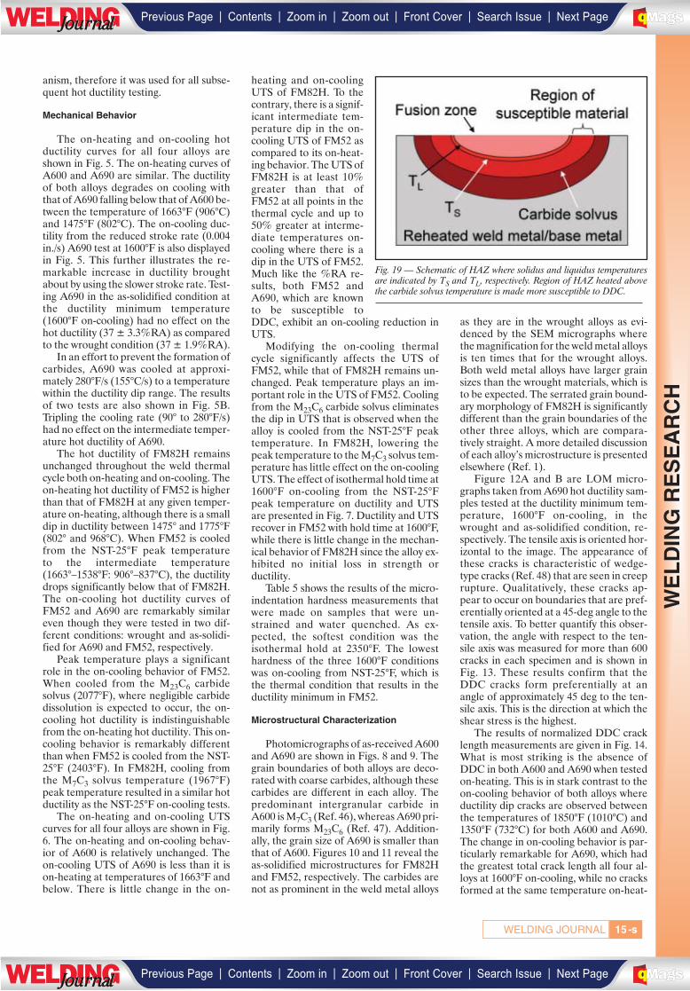
anism, therefore it was used for all subse-quent hot ductility testing.
Mechanical Behavior
The on-heating and on-cooling hotductility curves for all four alloys areshown in Fig. 5. The on-heating curves ofA600 and A690 are similar. The ductilityof both alloys degrades on cooling withthat of A690 falling below that of A600 be-tween the temperature of 1663°F (906°C)and 1475°F (802°C). The on-cooling duc-tility from the reduced stroke rate (0.004in./s) A690 test at 1600°F is also displayedin Fig. 5. This further illustrates the re-markable increase in ductility broughtabout by using the slower stroke rate. Test-ing A690 in the as-solidified condition atthe ductility minimum temperature(1600°F on-cooling) had no effect on thehot ductility (37 ± 3.3%RA) as comparedto the wrought condition (37 ± 1.9%RA).
In an effort to prevent the formation ofcarbides, A690 was cooled at approxi-mately 280°F/s (155°C/s) to a temperaturewithin the ductility dip range. The resultsof two tests are also shown in Fig. 5B.Tripling the cooling rate (90° to 280°F/s)had no effect on the intermediate temper-ature hot ductility of A690.
The hot ductility of FM82H remainsunchanged throughout the weld thermalcycle both on-heating and on-cooling. Theon-heating hot ductility of FM52 is higherthan that of FM82H at any given temper-ature on-heating, although there is a smalldip in ductility between 1475° and 1775°F(802° and 968°C). When FM52 is cooledfrom the NST-25°F peak temperature to the intermediate temperature(1663°–1538°F: 906°–837°C), the ductilitydrops significantly below that of FM82H.The on-cooling hot ductility curves ofFM52 and A690 are remarkably similareven though they were tested in two dif-ferent conditions: wrought and as-solidi-fied for A690 and FM52, respectively.
Peak temperature plays a significantrole in the on-cooling behavior of FM52.When cooled from the M23C6 carbidesolvus (2077°F), where negligible carbidedissolution is expected to occur, the on-cooling hot ductility is indistinguishablefrom the on-heating hot ductility. This on-cooling behavior is remarkably differentthan when FM52 is cooled from the NST-25°F (2403°F). In FM82H, cooling fromthe M7C3 solvus temperature (1967°F)peak temperature resulted in a similar hotductility as the NST-25°F on-cooling tests.
The on-heating and on-cooling UTScurves for all four alloys are shown in Fig.6. The on-heating and on-cooling behav-ior of A600 is relatively unchanged. Theon-cooling UTS of A690 is less than it ison-heating at temperatures of 1663°F andbelow. There is little change in the on-
heating and on-coolingUTS of FM82H. To thecontrary, there is a signif-icant intermediate tem-perature dip in the on-cooling UTS of FM52 ascompared to its on-heat-ing behavior. The UTS ofFM82H is at least 10%greater than that ofFM52 at all points in thethermal cycle and up to50% greater at interme-diate temperatures on-cooling where there is adip in the UTS of FM52.Much like the %RA re-sults, both FM52 andA690, which are knownto be susceptible toDDC, exhibit an on-cooling reduction inUTS.
Modifying the on-cooling thermalcycle significantly affects the UTS ofFM52, while that of FM82H remains un-changed. Peak temperature plays an im-portant role in the UTS of FM52. Coolingfrom the M23C6 carbide solvus eliminatesthe dip in UTS that is observed when thealloy is cooled from the NST-25°F peaktemperature. In FM82H, lowering thepeak temperature to the M7C3 solvus tem-perature has little effect on the on-coolingUTS. The effect of isothermal hold time at1600°F on-cooling from the NST-25°Fpeak temperature on ductility and UTSare presented in Fig. 7. Ductility and UTSrecover in FM52 with hold time at 1600°F,while there is little change in the mechan-ical behavior of FM82H since the alloy ex-hibited no initial loss in strength or ductility.
Table 5 shows the results of the micro-indentation hardness measurements thatwere made on samples that were un-strained and water quenched. As ex-pected, the softest condition was theisothermal hold at 2350°F. The lowesthardness of the three 1600°F conditionswas on-cooling from NST-25°F, which isthe thermal condition that results in theductility minimum in FM52.
Microstructural Characterization
Photomicrographs of as-received A600and A690 are shown in Figs. 8 and 9. Thegrain boundaries of both alloys are deco-rated with coarse carbides, although thesecarbides are different in each alloy. Thepredominant intergranular carbide inA600 is M7C3 (Ref. 46), whereas A690 pri-marily forms M23C6 (Ref. 47). Addition-ally, the grain size of A690 is smaller thanthat of A600. Figures 10 and 11 reveal theas-solidified microstructures for FM82Hand FM52, respectively. The carbides arenot as prominent in the weld metal alloys
as they are in the wrought alloys as evi-denced by the SEM micrographs wherethe magnification for the weld metal alloysis ten times that for the wrought alloys.Both weld metal alloys have larger grainsizes than the wrought materials, which isto be expected. The serrated grain bound-ary morphology of FM82H is significantlydifferent than the grain boundaries of theother three alloys, which are compara-tively straight. A more detailed discussionof each alloy’s microstructure is presentedelsewhere (Ref. 1).
Figure 12A and B are LOM micro-graphs taken from A690 hot ductility sam-ples tested at the ductility minimum tem-perature, 1600°F on-cooling, in thewrought and as-solidified condition, re-spectively. The tensile axis is oriented hor-izontal to the image. The appearance ofthese cracks is characteristic of wedge-type cracks (Ref. 48) that are seen in creeprupture. Qualitatively, these cracks ap-pear to occur on boundaries that are pref-erentially oriented at a 45-deg angle to thetensile axis. To better quantify this obser-vation, the angle with respect to the ten-sile axis was measured for more than 600cracks in each specimen and is shown inFig. 13. These results confirm that theDDC cracks form preferentially at anangle of approximately 45 deg to the ten-sile axis. This is the direction at which theshear stress is the highest.
The results of normalized DDC cracklength measurements are given in Fig. 14.What is most striking is the absence ofDDC in both A600 and A690 when testedon-heating. This is in stark contrast to theon-cooling behavior of both alloys whereductility dip cracks are observed betweenthe temperatures of 1850°F (1010°C) and1350°F (732°C) for both A600 and A690.The change in on-cooling behavior is par-ticularly remarkable for A690, which hadthe greatest total crack length all four al-loys at 1600°F on-cooling, while no cracksformed at the same temperature on-heat-
Fig. 19 — Schematic of HAZ where solidus and liquidus temperaturesare indicated by TS and TL, respectively. Region of HAZ heated abovethe carbide solvus temperature is made more susceptible to DDC.
-s15WELDING JOURNAL
WE
LD
ING
RE
SE
AR
CH
| | | | | |Previous Page Contents Zoom in Zoom out Front Cover Search Issue Next PageLWE DINGJournalJournal BA
M SaGEF
| | | | | |Previous Page Contents Zoom in Zoom out Front Cover Search Issue Next PageLWE DINGJournalJournal BA
M SaGEF
ing. The normalized crack length of A690at this temperature on-cooling was greatlyreduced from 23 to 1.7 μm/mm in the sam-ple tested at the slower stroke rate (0.004in./s).
Ductility dip cracks were observed inFM82H and FM52 both on-heating and on-cooling. The magnitude of DDC cracklength, and the temperature range at whichthey were observed, was greater for FM52than FM82H. In general, the amount ofDDC in FM52 was greater on-cooling thanon-heating, whereas there was little differ-ence between the on-heating and on-cool-ing cracking behavior of FM82H except at1600°F on-heating. Cooling from the re-spective carbide solvus temperature re-duces the ductility dip cracking susceptibil-ity of both FM82H and FM52.
Hot ductility samples were examinedusing LOM to determine the nature andextent of recrystallization. Two generaltypes of recrystallized grain structureswere observed in the hot ductility samples:uniform and localized. Figure 15A is aLOM micrograph showing the uniform re-crystallization behavior in A690 at 1850°Fon-heating. This type of recrystallizationbehavior was only observed in A600 andA690 samples on-heating, and associatedwith the greatest resistance to DDC. Thesecond type of recrystallization behavior isshown in Fig. 15B, which is taken fromA690 at 1850°F on-cooling. The recrystal-lized grains are much more localized alongthe grain boundary. This type of recrystal-lized grain structure was observed in A600and A690 on-cooling, and in both FM82Hand FM52 on-heating and on-cooling. Lo-calized recrystallized grains were oftenfound ahead of DDC cracks, as shown inFig. 16 for FM52 at 2100°F on-cooling.This figure also shows that DDC crackscan form at temperatures above theM23C6 carbide solvus (2077°F: 1136°C)where these intergranular carbides havebeen fully dissolved (Ref. 1) and are notexpected to precipitate during hot ductil-ity testing.
Discussion
Much of the recent research into DDChas been performed within the weldingcommunity, and it has been viewed as aweldability issue. However, DDC has alsobeen investigated in materials that undergothermomechanical treatment. As early asthe 1960s, intergranular cracks that wereformed at temperatures above 0.5 Tm wererecognized as the most common cause offracture in hot working of materials (Ref.49). Hot working is characterized by tem-peratures above 0.5 Tm and strain rates be-tween 10–3 – 103 s–1 (Ref. 50). This is signif-icant because strain rate and temperatureaffect deformation mechanisms. Addition-
ally, hot working research has investigatedthe same range of strain rates and temper-atures that have been used in the weldabil-ity studies of DDC, including this investiga-tion where the strain rate was betweenapproximately 1 and 2 s–1 and the tempera-ture ranged between approximately 0.55and 0.95 Tm. Ductility dip cracking has longbeen observed during the hot working ofmaterials, although not using the DDCnomenclature (Refs. 49–51). Therefore, thehot working literature can be quite useful infurthering the understanding of DDC inweld metal.
Comparison of Ductility and UTS
Using carefully controlled hot torsionquench studies on A600, Shapiro and Dieter found that intergranular cracksformed at the peak torque (Ref. 51). Thepeak torque is analogous to peak load, orUTS, in the tension (Gleeble®) testingperformed in the present investigation.The intermediate temperature dip in duc-tility in A690 and FM52 also results in adecrease in UTS. Both mechanical mea-sures of DDC have the same root cause:the formation of ductility dip cracks. Asthese cracks form, they impair an alloy’sability to macroscopically deform andstrain harden, thereby decreasing bothductility and the UTS.
Additionally, both ductility and UTS re-cover with hold time in FM52. Neither ex-hibits an intermediate temperature dipwhen FM52 is cooled from the M23C6solvustemperature (where carbide dissolution isnot expected due to the very short time atthe solvus temperature). Both mechanicalmeasures of DDC investigated in this workprovide reasonable predictions of a mater-ial’s DDC susceptibility. The advantage ofusing UTS as a measure of DDC suscepti-bility is in its simplicity. There are no post-test measurements when using UTS, unlike%RA. Rather, the peak load can be directlyobtained from the load cell data generatedduring the test. It should be noted that UTSmay not be a good indicator of DDC sus-ceptibility in other alloy systems and condi-tions. Further, work may be needed to as-sess this.
Comparison of Mechanical andMicrostructural Data
The crack count data provide insightinto how microstructural features (cracks)affect macroscopic properties (ductilityand UTS). The ductility minimums in bothFM52 and A690 correspond to the peak inmaximum crack length per length of grainboundary. The crack count data also re-veal key information regarding crackingsusceptibility that could not be discernedfrom the macroscopic measurements ofductility and UTS. The following are sev-
eral examples. First, the on-heating hotductility data for FM82H are very similarto those of A600 and A690, yet onlyFM82H forms DDC cracks on-heating.This difference in cracking susceptibilitycan only be discerned from the micro-scopic DDC crack measurements (Fig. 5vs. Fig. 14). Second, the hot ductility ofFM52 is similar to, and often higher than,FM82H (Fig. 5) during the on-heatingportion of the thermal cycle, yet FM52 hasa greater tendency to form DDC — Fig.14. This difference underscores that me-chanical measurements of DDC are notonly affected by the formation of DDCcracks, but also by an alloy’s ability to dy-namically recover and recrystallize. Theeffects of alloy composition on dynamicrecovery and recrystallization must beconsidered when comparing hot tensiledata between alloys. It has been shownthat alloying additions of Nb decreaseboth dynamic recovery and dynamic re-crystallization in austenite (Ref. 52). Re-ducing these two restoration processesmay explain why the on-heating ductilitybetween the temperatures of 1100° and1350°F of FM82H, which contains Nb, isequal to or lower than that of FM52 eventhough FM82H has higher resistance toDDC than FM52.
Overall, the mechanical and mi-crostructural measures of DDC are com-plementary. Crack length measurementson fractured hot tensile specimens pro-vide direct information about an alloy’spropensity to form ductility dip cracks.However, these measurements do notprovide information on the level of stressor strain at which DDC cracks form. Thestrain at which DDC cracks begin to formcan be inferred from the mechanical mea-sures of DDC: ductility and UTS. As DDCcracks nucleate and grow, they form inter-nal free surfaces that decrease the effec-tive cross-sectional area of the sample andimpair the alloy’s ability to carry a givenload. The formation of ductility dip cracksthereby brings about a reduction in UTSas compared to an alloy condition that ismore resistant to DDC (e.g., FM52 1600°Fon-heating vs. 1600°F on-cooling). Fur-thermore, the DDC cracks degrade analloy’s ability to deform, which will resultin a decrease in %RA since prematurefracture will occur due to the nucleationand growth of DDC cracks, as opposed toa purely ductile mechanism, such as mi-crovoid coalescence. The similar on-cool-ing hot ductility behavior of A690 andFM52 indicate that DDC cracks form atapproximately the same level of strain,even though their grain size is significantlydifferent: 93 ± 13 μm vs. 263 ± 13 μm, forA690 and FM52, respectively at 1600°F
-s16 JANUARY 2009, VOL. 88
WE
LD
ING
RE
SE
AR
CH
| | | | | |Previous Page Contents Zoom in Zoom out Front Cover Search Issue Next PageLWE DINGJournalJournal BA
M SaGEF
| | | | | |Previous Page Contents Zoom in Zoom out Front Cover Search Issue Next PageLWE DINGJournalJournal BA
M SaGEF
on-cooling (Ref. 1).While the specific reason for the par-
ticularly high value at 1725°F for FM52on-heating is currently not known, aspointed out in the discussion section, thehigh value of normalized crack length gen-erally correlates with the minimum in duc-tility (i.e., compare Figs. 5 and 14). Rea-sonable agreement exists between themacroscopic mechanical measures ofDDC and microscopic cracking suscepti-bility; therefore, the hot ductility test reli-ably predicts which alloys will exhibit agreater tendency to DDC.
Microstructural Factors AffectingDuctility and UTS
Qualitatively, it has been suggestedthat DDC cracks form over a preferredorientation of angles oriented between 45and 90 deg to the tensile axis (Ref. 9). Thisqualitative observation appears consistentwith the cracking observations for A690 atthe on-cooling ductility minimum(1600°F) as seen in Fig. 12. Quantificationof these cracking data shows that there isindeed a preference for cracks to formalong boundaries oriented 45 deg to thetensile axis (Fig. 13), for samples tested inwrought and as-solidified condition,which is the angle at which maximal shearis expected to occur. However, the distri-bution of cracks is not normal about 45deg, which would be expected if grainboundary sliding was an operative mecha-nism in DDC. Rather, the distribution isskewed to higher angles. The distributionfor the wrought data is more skewed thanit is for the as-solidified. This difference inthese two distributions is probably due tothe difference in grain shape. The wroughtsample consisted of equiaxed grains,whereas the grains in the as-solidifiedsample were preferentially oriented withrespect to the tensile axis, thereby intro-ducing some bias into the crack orienta-tion measurement.
Nonetheless, both the wrought and as-solidified data are not normal about 45deg. This is due to the limitations of thestereological technique employed. Figure17 is a schematic illustration that showshow a grain boundary plane may be ori-ented within a given volume of material.In this instance, the intersection of thegrain boundary plane with the plane ofview forms a grain boundary line that isorientated at a 90-deg angle to the tensileaxis. This is the angle that is measuredusing standard image analysis techniques.In reality, the angle between the grainboundary plane and the tensile axis is at 45deg. It is not possible to measure this anglefrom a single plane of view. Ideally, theorientation of the grain boundary planecould be plotted as a function of angle with
respect to the tensile direction. Some at-tempts have been made to correct for thelimitations of measuring the orientation ofthe grain boundary line to the tensile axis.Scriven and Williams attempted to mea-sure the angular distribution of cavitatedboundaries in copper that was subjected tofatigue testing at 400°C (Ref. 53). Theirangular distribution curve is very similarto that seen in Fig. 13 for DDC cracking inA690. They concluded that this type of an-gular distribution demonstrates thatboundaries oriented in the direction ofmaximal shear preferentially cavitated.With reference to DDC of A690, grainboundaries oriented along the direction ofmaximal shear force are most likely toductility dip crack. This suggests that grainboundary sliding is an operative mecha-nism in DDC.
Furthermore, the ductility dip cracks inboth the wrought and as-solidified samples(Fig. 12) are shaped like wedge-type cracks(w-cracks) that are observed during creep athigh stresses and low temperature (Ref. 54).It is widely accepted that wedge-type cracksare formed as a result of grain boundarysliding (GBS) (Refs. 48, 54–57). There aretwo general types of GBS: Lifshitz andRachinger (Ref. 58). Lifshitz sliding is thedirect result of stress-directed diffusion ofvacancies, whereas Rachinger sliding is ac-commodated by intragranular deformation(Ref. 58). During Rachinger GBS, the grainboundaries remain contiguous if the intra-granular deformation can fully accommo-date the GBS. Wedge-type cracks formwhen intragranular slip occurs at a slowerrate than GBS. As such, alloy changes thatimpede intragranular slip but do not alsodecrease GBS would be expected to in-crease the propensity to form wedge cracks.This may be the case with A690 and A600,which are both solid-solution-strengthenedalloys. Alloy 690 contains approximately 15wt-% more chromium than A600, and isalso more susceptible to DDC. The in-creased chromium concentration in A690may sufficiently strengthen the grain inte-rior to disrupt the balance of GBS and in-tragranular slip necessary to avoid inter-granular cracking. Similarly, thesusceptibility to form wedge cracks could bedecreased by changes to the alloy that im-pede grain boundary sliding, like the for-mation of intergranular precipitates and/orserrated grain boundaries. As discussed inthe second paper in this series, both A690and FM52 have fewer obstacles to grainboundary sliding at the ductility minimumtemperature than either A600 or FM82H(Ref. 1). The combined increase in intra-granular strength and decrease in resistanceto GBS may significantly contribute to theDDC susceptibility of A690 and FM52.
Wedge-type cracks have been observedin the hot torsion of Nickel 270 at tempera-
tures ranging from 800°F (427°C) up to2000°F (1093°C) with strain rates up to 70s–1 (Ref. 59). However, wedge cracks arenot expected to form during hot tensiontesting of nickel at strain rates higher than 1s–1 for temperatures less than 1700°F(927°C) (Ref. 55). This indicates that thedifference in loading condition (tension vs.torsion) may affect the formation of wedgecracks. Nonetheless, in this current workDDCs form as wedge-type cracks; there-fore, GBS appears to play a significant rolein DDC given the test conditions employed.
Dynamic recrystallization has been citedby several authors in the welding literatureas an elevated temperature recovery mech-anism that brings about an increase in hotductility at temperatures above the ductilitydip temperature (Refs. 11, 26, 60). Recov-ery and recrystallization are the two generalclasses of restoration processes that reducethe internal energy of a deformed material.Recovery consists of the rearrangement ofdislocations into low angle boundaries,which delineate subgrains. Recovery re-quires that the dislocations be able to climband cross-slip, which are hindered in mate-rials with moderate to low stacking fault en-ergy where the dislocations disassociateinto partial dislocations. In materials withlow stacking fault energy, recrystallization isthe preferred method of recovery since theclimb and cross-slip of dislocations is notnecessary (Ref. 61). Rather, new unstrainedgrains form at locations of high lattice strainenergy that is brought about by inhomo-geneities in the deformed microstructure.These can include grain boundaries, twin in-tersections, and shear bands (Ref. 62).
Dynamic recrystallization (DRX) is afunction of strain rate, temperature, storeddeformation energy in the form of disloca-tions, and grain size (Refs. 63, 64). Formingdynamically recrystallized grains signifi-cantly increases ductility (Ref. 50). The no-ticeable increase in on-heating hot-ductilityin A600 and A690 at temperatures of1600°F (871°C) and above can be explainedby the increase in dynamically recrystallizedgrains. One way dynamically recrystallizedgrains act to increase ductility at elevatedtemperatures is by preventing ductility dipcrack propagation. This can be seen in Fig.16 where the ductility dip crack is com-pletely surrounded by recrystallized grainsthat prevent its further growth.
In the micrographs for A690 shown inFig. 15A and B, the strain rate and tem-perature (1850°F ) are the same; however,there is a significant difference in recrys-tallization behavior. This can be explainedby a change in intergranular carbide dis-tribution that affects both grain size andthe delocalization of grain boundarystresses. The intergranular carbides ob-served in as-received A690 (Fig. 9B) dis-solve during the peak temperature portion
-s17WELDING JOURNAL
WE
LD
ING
RE
SE
AR
CH
| | | | | |Previous Page Contents Zoom in Zoom out Front Cover Search Issue Next PageLWE DINGJournalJournal BA
M SaGEF
| | | | | |Previous Page Contents Zoom in Zoom out Front Cover Search Issue Next PageLWE DINGJournalJournal BA
M SaGEF
of the thermal cycle that is above theM23C6 solvus temperature, which resultsin grain growth. The average grain size ofA690 at 1850°F on-heating is approxi-mately 30 μm, while that at 1850°F on-cooling is 88 μm (Ref. 1). Grain size has asignificant effect on DRX. In austenite ithas been shown that smaller initial grainsizes decrease 1) the critical strain re-quired for dynamic recrystallization and2) the temperatures required for DRXgiven a certain strain (Ref. 65). Further-more, recrystallized grains will tend to lo-calize along the grain boundary and forma necklace structure as the initial grain sizeincreases (Ref. 63). A similar effect alsooccurs in A600 where the dissolution ofM7C3 results in an increase of on-coolinggrain sizes and localization of dynamicallyrecrystallized grains to the grain boundaries.
The dissolution of intergranular pre-cipitates acts in three ways to affect the dy-namic recrystallization behavior. The firstway is by localizing grain boundarystresses. Bruemmer et al. (Refs. 66, 67)performed a series of elegant in-situ de-formation studies of A600 using a high-voltage electron microscope (HVEM) tostudy the effects of intergranular precipi-tates on deformation behavior of A600.Intergranular precipitates were found tobe the principal dislocation sources inA600. These intergranular precipitatesacted to delocalize stresses that formedalong grain boundaries during deforma-tion. This resulted in more homogenousplastic deformation in A600 samples thatwere heat treated in order to form a highdensity of intergranular precipitates (Ref.67). Conversely, A600 that was subjectedto a thermal treatment that resulted infewer intergranular carbides exhibited de-formation that was localized to the regionsurrounding the grain boundary (Ref. 67).Based on this, it is expected that fewer in-tergranular carbides will result in strain localization along grain boundaries, and further prevent complete dynamic recrystallization.
The second way dissolution of inter-granular carbides affects DRX is by in-creasing the susceptibility of grain bound-aries to DDC cracking. Forming ductilitydip cracks generates internal free surfacesthat can no longer bear the loading force.This decreases the amount of deformationenergy that the material can effectively con-vert into strain energy. This decrease instrain energy in the crystal reduces the dri-ving force to bring about complete DRX.
Thirdly, dissolution of intergranular car-bides increases the grain size. When thegrain size is large compared to the recrys-tallized grain size the DRX grains will firstform along grain boundaries, then addi-tional DRX grains will form into the grain
interior as deformation increases. This isseen in Fig. 18A–D (Ref. 63) where a neck-lace structure of DRX grains forms alongthe grain boundaries when the initial grainsize is significantly larger than the recrystal-lized grain size. With increasing deforma-tion, the necklace structure is filled up withadditional DRX grains. However, if DDCcracks form this process will be interrupted.When the initial and recrystallized grainsizes are similar, recrystallized structure willappear like that shown in Fig. 18E. Thislater structure is what is observed in bothA600 and A690 at temperatures above1600°F on-heating — Fig. 15A and B.
Due to their role in delocalizing grainboundary stresses, intergranular precipi-tates may act to inhibit DDC nucleation.Thermal cycles that promote carbide pre-cipitation/coarsening result in decreasedDDC normalized crack length, as can beseen in Fig. 14. This is observed when thepeak temperature is lowered to the respec-tive carbide solvus temperatures in FM82Hand FM52, and when these alloys are sub-jected to an isothermal hold at 1600°F for 60s. An increase in intergranular carbide pre-cipitation is also expected to occur in theslow stroke rate testing performed on A690at 1600°F. The time under load in this con-dition was approximately 90 s, which islonger than the isothermal hold time re-quired to recover the hot ductility of FM52(which has nearly the same nominal com-position as A690) at the same temperature.The decrease in strain rate is also expectedto lower the critical strain required to formdynamically recrystallized grains, as hasbeen shown in Ni and Ni-Fe alloys (Ref. 68).This can be seen qualitatively in Fig. 4B andD where there are significantly more dy-namically recrystallized grains in the slowstroke sample tested at 1600°F on-cooling.
Whereas thermal cycles that resulted inthe dissolution of intergranular carbideswere found to increase DDC susceptibility,modifications to the thermal cycle that pro-moted the formation of intergranular car-bides decreased DDC susceptibility. In par-ticular, an isothermal hold at the on-coolingductility minimum for FM52, 1600°F, re-sulted in a recovery of both ductility andUTS. Time at elevated temperature canallow for recovery and recrystallization tosoften an alloy, which may lead to an in-crease in ductility. Therefore, microhard-ness measurements were made on un-strained samples of FM52 that underwentfour different thermal treatments followedby a water quench. The ductility minimumtemperature, 1600°F, is the temperature ofinterest; therefore, microhardness mea-surements were made on 1600°F samples inthree different conditions: 1) on-heating, 2)on-cooling from NST-25°F, and 3) on-cool-ing from NST-25°F followed by a 60-s hold.The hardness of these three samples was
compared to a fourth sample that acted asa control, which was subjected to a thermaltreatment that would be expected to resultin softening: an isothermal hold at 2350°F(1288°C) for 10 min. The results reveal thatthe 1600°F on-cooling from NST-25°F sam-ple had the lowest hardness of the three1600°F thermal conditions (Table 5). Onlythe sample subjected to a 10-min hold at2350°F was softer. The higher hardness ofboth the 1600°F on-heating and 60-s holdsample is most likely due to their higher vol-ume fraction of M23C6 precipitates. Thisshows that the recovery of ductility in FM52with hold time is not the result of annealing.
FM82H consists of two microstructuralfeatures that work to its advantage in pre-venting DDC nucleation and propagation.The most obvious distinctive feature ofFM82H are the serrated grain boundaries(Fig. 10A), which are expected to be highlyresistant to grain boundary sliding. Less ob-vious is the stability of the Nb-rich MC car-bides that form in FM82H, which is muchmore stable during the peak temperatureportion of the thermal cycle than the M23C6(A690 and FM52) and M7C3 (A600) inter-granular carbides (Ref. 1). These carbideslikely act to further impede grain boundarysliding and DDC nucleation.
It should be noted that DRX is generallynot observed adjacent to DDC cracks inmultipass welds. This is probably a result ofthe lower levels of strain that the alloys ex-perience during multipass welding as com-pared to hot ductility testing. Increasingtotal strain promotes DRX. However, asthis work shows, the faster strain rate resultsin a greater loss of on-cooling ductility at theductility dip temperature. Furthermore, theDDC mechanism is reproduced in the hotductility test, even if the recovery mecha-nisms observed in the hot ductility test maynot be operative in multipass welds.
Further Insights Into the Mechanism ofDDC
The results in this work show that inter-granular precipitates play a key role in sup-pressing ductility dip cracking. As men-tioned previously, thermal cycles designedto dissolve precipitates increase an alloy’stendency to localize strain along the grainboundaries and form DDC. Conversely,thermal cycles that result in precipitationand growth of intergranular carbides de-crease DDC susceptibility. The followingtest conditions all promoted intergranularprecipitation and all resulted in decreasedDDC susceptibility:
1. Cooling FM82H and FM52 from theirrespective carbide solvus temperatures
2. Isothermal hold at the on-cooling duc-tility minimum temperature
3. Slower stroke rate at on-cooling duc-tility minimum temperature.
-s18 JANUARY 2009, VOL. 88
WE
LD
ING
RE
SE
AR
CH
| | | | | |Previous Page Contents Zoom in Zoom out Front Cover Search Issue Next PageLWE DINGJournalJournal BA
M SaGEF
| | | | | |Previous Page Contents Zoom in Zoom out Front Cover Search Issue Next PageLWE DINGJournalJournal BA
M SaGEF
This work indicates that regions of thereheated weld metal where the peak tem-perature exceeds the intergranular carbidesolvus temperature will be made vulnerableto DDC. This is shown schematically in Fig.19 where several key isotherms are overlaidonto a HAZ. Regions heated above the car-bide solvus, but below the liquidus, are ex-pected to become more vulnerable to DDC.The size of this vulnerable region of weldmetal can be decreased by forming inter-granular precipitates that are stable athigher temperature, as is the case in NbCforming FM82H.
Ductility dip cracking forms preferen-tially along grain boundaries oriented at a45-deg angle with respect to the tensile axis.This indicates that grain boundary slidingplays a role in DDC. Furthermore, DDCcracks are observed at temperatures abovethe M23C6 carbide solvus for FM52 (2100°F(1149°C) both on-heating and on-cooling.This can be explained by grain boundarysliding, but not by the current form of theprecipitation-induced cracking hypothesis(Refs. 19, 29) since at 2100°F M23C6 car-bides in FM52 are 1) not present and 2) notexpected to form during the hot ductilitytest since the test temperature is above theM23C6 solvus (2077°F (1136°C)). Furtherinsights into the DDC mechanism and theinfluence of microstructural condition onDDC susceptibility will be discussed in thePart II companion paper (Ref. 1).
Conclusions
The DDC susceptibility of Alloys 600and 690 have been investigated along withtheir companion filler metals (FM52 andFM82H, respectively) using a combinationof Gleeble® hot ductility testing and mi-crostructural characterization techniques.The following conclusions can be drawnfrom this research:
1. A high stroke rate (2 in./s (50.8 mm/s))resulted in greater DDC susceptibility inthe Gleeble® hot ductility test than a slowerstroke rate (0.004 in./s (0.1 mm/s)) at theductility minimum temperature of 1600°Fon-cooling. Slower stroke rates are ex-pected to result in more intergranular pre-cipitation and dynamic recrystallization.
2. Ductility and UTS are reliable macro-scopic indicators of DDC in the solid-solu-tion-strengthened, Ni-based alloys tested inthis work. Additionally, they provide an in-direct measure of when DDC begins toform in an alloy.
3. Crack count measurements on hotductility specimens provide a more directassessment of cracking susceptibility thanmacroscopic mechanical measures (ductil-ity and UTS); however, crack counts aremuch more time consuming and do not pro-vide information on the strains/stresses re-quired to form DDC.
4. The greatest resistance to DDC wasobserved in A600 and A690 at all tempera-tures on-heating. Strain was uniformly dis-tributed within these samples as evidencedby uniform dynamically recrystallizedgrains.
5. The hot ductility of FM52 and A690,both of which are susceptible to DDC, bothdipped well below the minimum ductility ofA600 and FM82H when cooled from a nearNST peak temperature.
6. In general, alloys were most suscepti-ble to form DDC when cooled from a peaktemperature near the NST of the alloy andtested at an intermediate temperature cor-responding to a homologous temperatureof approximately 0.72.
7. Peak temperature has a significant ef-fect on the on-cooling DDC susceptibility ofFM52. DDC resistance is increased whenFM52 is cooled from the M23C6 solvus tem-perature, as compared to the super solvusNST-25°F peak temperature. The near NSTpeak temperature results in the dissolutionof intergranular M23C6 carbides (Ref. 1),which promotes grain boundary sliding andDDC.
8. Hot ductility and UTS can be recov-ered in FM52 by isothermally holding at theductility minimum temperature for 60 s. This recovery is not associated with anannealing effect. This recovery appears tobe the result of decreased susceptibility tograin boundary sliding due to increased in-tergranular carbide coverage.
Acknowledgments
This work was funded by a Naval Nu-clear Propulsion Program Fellowship spon-sored by Naval Reactors Division of theU.S. Department of Energy. The authorswould like to thank Dr. George Young Jr.,Tom Capobianco, Steve Rooney, and DanBozik of Lockheed Martin for their assis-tance in this work. Additionally, Noeckerthanks Dr. Tom Lienert of Los Alamos Na-tional Laboratory for his continuing interestin this work and helpful discussions.
References
1. Noecker II, F. F., and DuPont, J. N. 2007.Metallurgical investigation into ductility dipcracking in Ni-based alloys: Part II — Mi-crostructural and microchemical development ischaracterized during simulated weld reheat ther-mal cycle and correlated to ductility dip crackingsusceptibility. Submitted for publication to theWelding Journal.
2. International Energy Agency. 2007. KeyWorld Energy Statistics — 2007.http://www.iea.org/Textbase/publications/free_new_Desc.asp?PUBS_ID=1199.
3. Saunders, S. 2007–2008. Jane’s FightingShips. Alexandria, Jane’s Information Group,801.
4. Bamford, W. H. J. 2003. A review of Alloy600 cracking in operating nuclear plants: Histor-
ical experience and future trends. Eleventh Inter-national Conference on Environmental Degrada-tion of Materials in Nuclear Power Systems–WaterReactors. W. Stevenson, 1071–1081. AmericanNuclear Society.
5. Gorman, J. A., and Staehle, R. W. 2001.Corrosion problems in the nuclear power indus-try and implications for the future. Proceedings ofChemistry and Electrochemistry of Corrosion andStress Corrosion Cracking Symposium. R. H.Jones and R. W. Staehle, 397–419. TMS.
6. Harrod, D. L., Gold, R. E., and Jacko, R. J.2001. Alloy optimization for PWR steam gener-ator heat-transfer tubing. JOM 53(7): 14–17.
7. Strauss, S. D. 1996. Inconel 690 is alloy ofchoice for steam-generator tubing. Power 140(2):29–30.
8. Nissley, N. E., and Lippold, J. C. 2003. De-velopment of the strain-to-fracture test: A newtest has been established for evaluating ductilitydip cracking susceptibility in austenitic alloys.Welding Journal 82(12): 355-s to 364-s.
9. Collins, M. G., and Lippold, J. C. 2003. Aninvestigation of ductility dip cracking in nickel-based filler materials. Part I: The strain-to-frac-ture test has been used to develop temperature-strain relationships for ductility dip cracking.Welding Journal 82(10): 288-s to 295-s.
10. Collins, M. G., Ramirez, A. J., and Lip-pold, J. C. 2003. An investigation of ductility dipcracking in nickel-based weld metals. Part II:Fracture behavior and fracture surface morphol-ogy are related to microstructure, composition,and temperature. Welding Journal 82(12): 348-s to354-s.
11. Collins, M. G., Ramirez, A. J., and Lip-pold, J. C. 2004. An investigation of ductility-dipcracking in nickel-based weld metals. Part III:The characteristics of weld-metal grain bound-aries associated with elevated-temperature frac-ture are investigated. Welding Journal 83(2): 39-sto 49-s.
12. Ramirez, A. J., and Lippold, J. C. 2004.High temperature behavior of Ni-base weldmetal. Part I: Ductility and microstructural char-acterization. Materials Science & Engineering AA380(1-2): 259–271.
13. Ramirez, A. J., and Lippold, J. C. 2004.High temperature behavior of Ni-base weldmetal. Part II: Insight into the mechanism forductility dip cracking. Materials Science & Engi-neering A A380(1-2): 245–258.
14. Ramirez, A. J., Sowards, J. W., and Lip-pold, J. C. 2006. Improving the ductility-dipcracking resistance of Ni-base alloys. Journal ofMaterials Processing Technology 179(1–3):212–218.
15. Nishimoto, K., Saida, K., and Okauchi, H.2006. Microcracking in multipass weld metal ofAlloy 690. Part 1: Microcracking susceptibility inreheated weld metal. Science and Technology ofWelding and Joining 11(4): 455–461.
16. Nishimoto, K., Saida, K., Okauchi, H., andOhta, K. 2006. Microcracking in multipass weldmetal of Alloy 690. Part 2: Microcracking mech-anism in reheated weld metal. Science and Tech-nology of Welding and Joining 11(4): 462–470.
17. Nishimoto, K., Saida, K., Okauchi, H., andOhta, K. 2006. Microcracking in multipass weldmetal of Alloy 690. Part 3: Prevention of microc-racking in reheated weld metal by addition of Lato filler metal. Science and Technology of Weldingand Joining 11(4): 471–479.
18. Dave, V. R., Cola, M. J., Kumar, M.,Schwartz, A. J., and Hussen, G. N. A. 2004.
-s19WELDING JOURNAL
WE
LD
ING
RE
SE
AR
CH
| | | | | |Previous Page Contents Zoom in Zoom out Front Cover Search Issue Next PageLWE DINGJournalJournal BA
M SaGEF
| | | | | |Previous Page Contents Zoom in Zoom out Front Cover Search Issue Next PageLWE DINGJournalJournal BA
M SaGEF
_________________________________________

Grain boundary character in Alloy 690 and duc-tility-dip cracking susceptibility. Welding Jour-nal 83(1): 1-s to 5-s.
19. Young, G. A., Capobianco, T. E., andEtien, R. 2007. Development of a highly weldableand corrosion resistant Ni-Cr filler metal. Degra-dation 2007: 13th International Conference on En-vironmental Degradation in Nuclear Power Sys-tems. Eds. T. R. Allen, J. T. Busby, and P. T. King,compact disc (CD). Canadian Nuclear Society.
20. Nishimoto, K., Mori, H., and Hirata, H.2001. Effect of grain boundary segregation of sul-phur on reheat cracking susceptibility in multi-pass weld metal of Fe-36%Ni alloy. Today and To-morrow in Science and Technology of Welding andJoining, Proceedings of the 7th Japanese WeldingSociety International Symposium. T. Ohji, pp.827–832. Japan Welding Society.
21. Nishimoto, K., Hongou, S., Kubo, N.,Koga, S., Nagatani, H., Ogawa, K., and Hirata, H.2001. Hot cracking and its prevention in multi-pass weld metal of Fe-36% Ni Invar alloy. Todayand Tomorrow in Science and Technology of Weld-ing and Joining, Proceedings of the 7th JapaneseWelding Society International Symposium. T. Ohji,pp. 833–838. Japan Welding Society.
22. Nakagawa, H., Matsuda, F., Nagai, A., andSakabata, N. 1980. Weldability of Fe–36%Nialloy report I: Hot cracking with cross-bead test.Trans. JWRI 9(2): 55–62.
23. Matsuda, F., Nakagawa, H., Minehisa, S.,Sakabata, N., Ejima, A., and Nohara, K. 1984.Weldability of Fe-36% Ni alloy report II: Effectof chemical composition on reheated hot crack-ing in weld metal. Trans. JWRI 13(2): 69–75.
24. Zhang, Y. C., Nakagawa, H., and Mat-suda, F. 1985. Weldability of Fe-36%Ni alloy re-port III: Dynamic observation of reheat hot crackand evaluation of hot ductility of reheated weldmetal. Trans. JWRI 14(1): 107–114.
25. Zhang, Y. C., Nakagawa, H., and Mat-suda, F. 1985. Weldability of Fe-36%Ni alloy re-port IV: Dynamic observation of reheat hotcracking in weld metal by means of hot stage mi-croscope. Trans. JWRI 14(2): 113–117.
26. Zhang, Y. C., Nakagawa, H., and Mat-suda, F. 1985. Weldability of Fe-36%Ni alloy re-port V: Behaviors of grain-boundary sliding andcavity formation preceding reheat hot cracking inweld metal. Trans. JWRI 14(2): 119–124.
27. Zhang, Y. C., Nakagawa, H., and Mat-suda, F. 1985. Weldability of Fe-36%Ni alloy re-port VI: Further investigation on mechanism ofreheat hot cracking in weld metal. Trans. JWRI14(2): 125–134.
28. Rhines, F. N., and Wray, P. J. 1961. Inves-tigation of the intermediate-temperature ductil-ity minimum in metals. Am. Soc. Metals, Trans.Quartz 54(2): 117–128.
29. Young, G. A., Capobianco, T. E., Penik,M. A., Morris, B. W., and McGee, J. J. 2007. Themechanism of ductility dip cracking in nickel-chromium alloys. Welding Journal 87(2): 31-s to43-s.
30. Adonyi, Y., and Blodgett, O. 2006. Heat-affected zone characterization by physical simu-lations. Welding Journal 85(10): 42–47.
31. Savchenko, V. S., Yushchenko, K. A., andSavolei, N. I. 1988. Effect of strain rate on the hotcracking susceptibility of stable austenitic weldedjoints in the low temperature brittleness range.Welding International 2(10): 874–877.
32. Saunders, N., Guo, Z., Li, X., Miodownik,A. P., and Schille, J. P. 2003. Using JMatPro tomodel materials properties and behavior. JOM55(12): 60–65.
33. Saunders, N., Guo, Z., Li, X., Miodownik,A. P., and Schille, J. P. 2004. Modeling the mate-rial properties and behaviour of Ni-based super-alloys. Proceedings of the 10th International Sym-posium on Superalloys. Eds. K. A.Green et al., pp.849–858. TMS.
34. Low force jaw set for Gleeble® systems:Model 9510 series jaw sets information manual.Dynamic Systems Inc.
35. Schwartz, M. M. 1990. Ceramic Joining.Materials Park, Ohio: ASM International, 4.
36. Isoard, V., and Rack, H. J. 1997. High tem-perature grain growth in Inconel 690. THER-MEC ‘97, International Conference on Thermo-mechanical Processing of Steels and OtherMaterials, 2nd. Eds. T. Chandra and T. Sakai, pp.1737–1744. TMS.
37. Diano, P., Muggeo, A., Van Duysen, J. C.,and Guttmann, M. 1989. Relationship betweenmicrostructure and mechanical properties ofAlloy 690 tubes for steam generators. Journal ofNuclear Materials 168(3): 290–294.
38. Lee, J. A., Lee, J. H., Kim, J. J., and Chai,Y. S. 2005. Effects of heat treatment condition onthe microstructure evolution of Inconel 690. KeyEngineering Materials 297–300(1): 458–462.
39. Lim, Y. S., Hwang, S. S., Suh, J. H., andKim, J. S. 2001. Grain growth and intergranularcarbide precipitation in nickel-base Alloy 690.Recrystallization and Grain Growth, Proceedingsof the 1st Joint International Conference. Eds. G.Gottstein and D. A. Molodov, pp. 389–394.Springer-Verlag.
40. Scarberry, R. C., Pearman, S. C., andCrum, J. R. 1976. Precipitation reactions in In-conel Alloy 600 and their effect on corrosion be-havior. Corrosion 32(10): 401–406.
41. Lundin, C. D., Qiao, C. Y. P., and Lee, C.H. 1990. Standardization of Gleeble® hot ductil-ity testing. Part II: Experimental evaluation. Pro-ceedings of Materials Weldability Symposium. Eds.R. A. Patterson and K. W. Mahin, pp. 9–22. ASMInternational.
42. Noecker II, F. F., DuPont, J. N., Capo-bianco, T. E., Young Jr., G. A., Jordan, C. E.,Lewis, N., and Burke, M. G. 2005. Microstruc-tural characterization and hot ductility of nickelbased weldments. American Welding SocietyConference. Dallas, Tex.
43. Russ, J. C., and Dehoff, R. T. 2000. Prac-tical Stereology, 2nd Edition. New York: KluwerAcademic/Plenum Publisher, 56.
44. Standard Test Methods for Determining Av-erage Grain Size. 1996. ASTM E112-96. Con-shohocken, Pa.: American Society for Testing andMaterials.
45. Standard Test for Microhardness of Materi-als. 2005. ASTM E384 A. Conshohocken, Pa.:American Society for Testing and Materials.
46. Inconel Alloy 600. Special Metals, 2007. p.16.(http://www.specialmetals.com/documents/Inconel%20alloy%20600.pdf)
47. Inconel Alloy 690. Special Metals, 2007.p.8.(http://www.specialmetals.com/documents/Inconel%20alloy%20690.pdf)
48. Chang, H. C., and Grant, N. J. 1956.Mechanism of intercrystalline fracture. Journal ofMetals 8 (AIME Trans. 206): 544–551.
49. Tegart, W. J. M. 1967. The role of ductilityin hot working. Ductility, pp. 133–177. ASM In-ternational.
50. McQueen, H. J., and Jonas, J. J. 1975. Re-covery and recrystallization during high temper-ature deformation. Treatise on Materials Scienceand Technology 6: 393–493.
51. Shapiro, E., and Dieter, G. E. 1970. Hightemperature-high strain rate fracture of Inconel
600. Metallurgical Transactions 1: 1711–1719.52. Luton, M. J., Dorvel, R., and Petkovic, R.
A. 1980. Interaction between deformation, re-crystallization and precipitation in niobiumsteels. Metallurgical Transactions A 11A(3):411–420.
53. Scriven, R. A., and Williams, H. D. 1965.The derivation of angular distributions of planesby sectioning methods. Transactions of the Amer-ican Institute of Mining, Metallurgical and Petro-leum Engineers 233(8): 1593–1602.
54. Garofalo, F. 1967. Ductility in creep. Duc-tility. Eds. ASM International, pp. 87–132.
55. Gandhi, C., and Raj, R. 1981. An upperbound on strain rate for wedge type fracture innickel during creep. Metallurgical Transactions A12A(3): 515–520.
56. Waddington, J. S. 1968. Conditions affect-ing the mechanism of fracture at high tempera-tures. Philosophical Magazine 17(145): 51–59.
57. Williams, J. A. 1969. General approach tocreep failure resulting from wedge crack growth.Philosophical Magazine 20(165): 635–639.
58. Langdon, T. G. 2006. Grain boundary slid-ing revisited: Developments in sliding over fourdecades. Journal of Materials Science 41(3):597–609.
59. Shapiro, E., and Dieter, G. E. 1971. Frac-ture and ductility in hot torsion of nickel. Metal-lurgical Transactions 2(5): 1385–1391.
60. Yeniscavich, W. A. 1966. Correlation ofNi-Cr-Fe alloy weld metal fissuring with hot duc-tility behavior. Welding Journal 45(8): 344-s to356-s.
61. Humphreys, F. J., and Hatherly, M. 2004.Recrystallization and Related Annealing Phenom-ena. Oxford, Elsevier, 11–66.
62. Humphreys, F. J., and Hatherly, M. 2004.Recrystallization and Related Annealing Phenom-ena. Oxford, Elsevier, 215–266.
63. Humphreys, F. J., and Hatherly, M. 2004.Recrystallization and Related Annealing Phenom-ena. Oxford, Elsevier, 415–450.
64. Doherty, R. D., Hughes, D. A.,Humphreys, F. J., Jonas, J. J., Jensen, D. J., Kass-ner, M. E., King, W. E., McNelley, T. R., Mc-Queen, H. J., and Rollett, A. D. 1997. Current is-sues in recrystallization: A review. MaterialsScience & Engineering A A238(2): 219–274.
65. Suh, D. W., Cho, J. Y., and Nagai, K. 2004.Effect of initial grain size of austenite on hot-de-formed structure of Ni-30Fe alloy. Metallurgicaland Materials Transactions A 35A(11):3399–3408.
66. Bruemmer, S. M., Charlot, L. A., andHenager Jr., C. H. 1988. Microstructure and mi-crodeformation effects on intergranular stresscorrosion cracking of Alloy 600 steam generatortubing. Corrosion 44(11): 782–788.
67. Bruemmer, S. M., and Henager Jr., C. H.1986. High voltage electron microscopy observa-tions of microdeformation in Alloy 600 tubing.Scripta Metallurgica 20(6): 909–914.
68. Luton, M. J., and Sellars, C. M. 1969. Dy-namic recrystallization in nickel and nickel-ironalloys during high-temperature deformation.Acta Metallurgica 17(8): 1033–43.
-s20 JANUARY 2009, VOL. 88
WE
LD
ING
RE
SE
AR
CH
| | | | | |Previous Page Contents Zoom in Zoom out Front Cover Search Issue Next PageLWE DINGJournalJournal BA
M SaGEF
| | | | | |Previous Page Contents Zoom in Zoom out Front Cover Search Issue Next PageLWE DINGJournalJournal BA
M SaGEF
______________________________________
______________________________________
For Info go to www.aws.org/ad-index
| | | | | |Previous Page Contents Zoom in Zoom out Front Cover Search Issue Next PageLWE DINGJournalJournal BA
M SaGEF
| | | | | |Previous Page Contents Zoom in Zoom out Front Cover Search Issue Next PageLWE DINGJournalJournal BA
M SaGEF
______________ ______________

For Info go to www.aws.org/ad-index
| | | | | |Previous Page Contents Zoom in Zoom out Front Cover Search Issue Next PageLWE DINGJournalJournal BA
M SaGEF
| | | | | |Previous Page Contents Zoom in Zoom out Front Cover Search Issue Next PageLWE DINGJournalJournal BA
M SaGEF
________________________________________
_______________


![[PPT]Slide 1 · Web viewSSPC-SP WJ-1/NACE WJ-1, Clean to Bare Substrate SSPC-SP WJ-2/NACE WJ-2, Very Thorough Cleaning SSPC-SP WJ-3/NACE WJ-3, Thorough Cleaning SSPC-SP WJ-4/NACE](https://img.dokumen.tips/doc/110x75/5b191e557f8b9a46258c50b2/pptslide-1-web-viewsspc-sp-wj-1nace-wj-1-clean-to-bare-substrate-sspc-sp.jpg)