Embed Size (px)
Citation preview
Windscale Piles Decommissioning
Project
Presented by MT Cross, NUKEM Ltd, UK at the Brookhaven Graphite Research Reactor
Workshop, 9 -10 May, 2007

Introduction
• The Piles and their History
• Structure and present
condition
• Uncertainties for present
state/decommissioning
• Safety related issues
• Waste management of graphite
• Conclusions
Background
• Non-conventional large decommissioning project
(accident-damaged reactor with fire damaged core, not
all fuel removed)
• 2 reactors in safestore since core fire in Pile1, 1957
• Increasing regulatory pressure (2007, 50th anniversary
of fire)
• Characterisation issues dominate– some unique considerations
– intrusive inspection of fire-damaged region to be carried out
The decommissioning problem is dominated by the lack of a
detailed knowledge of the present state of the core
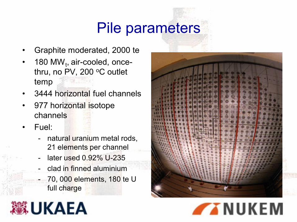
Pile parameters
• Graphite moderated, 2000 te
• 180 MW t, air-cooled, once-
thru, no PV, 200 oC outlet
temp
• 3444 horizontal fuel channels
• 977 horizontal isotope
channels
• Fuel:
- natural uranium metal rods,
21 elements per channel
- later used 0.92% U-235
- clad in finned aluminium
- 70, 000 elements, 180 te U
full charge
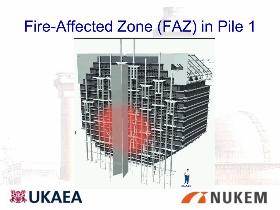
Fire-Affected Zone (FAZ) in Pile 1

Schematic structure
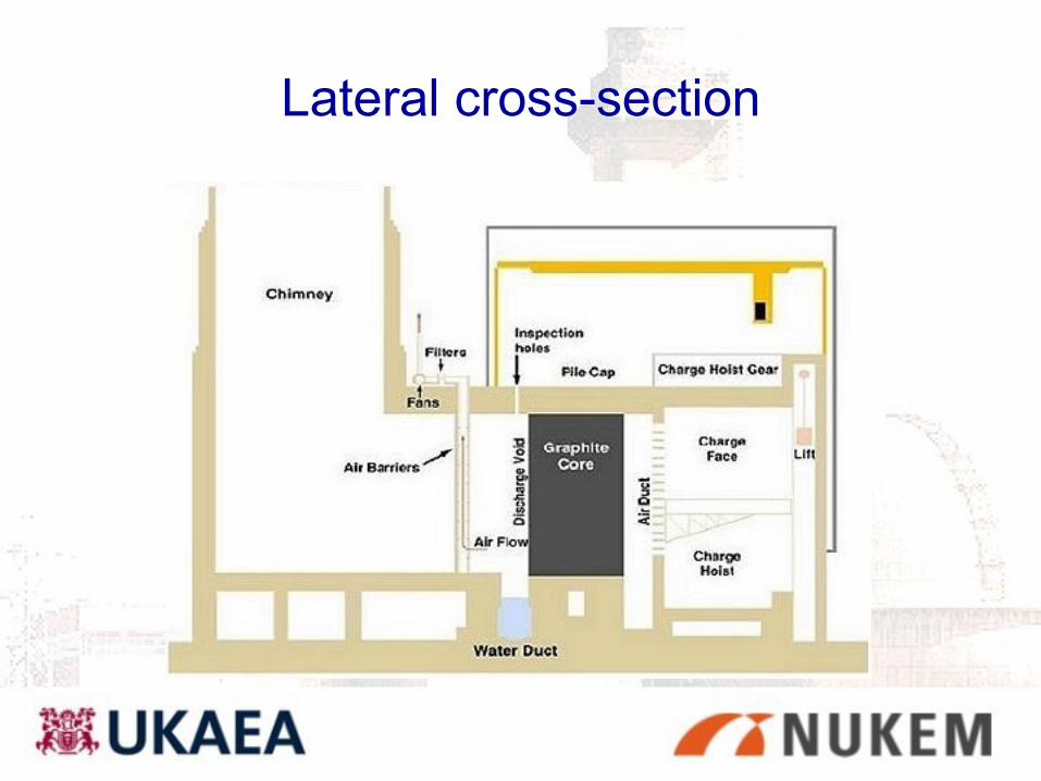
Lateral cross-section
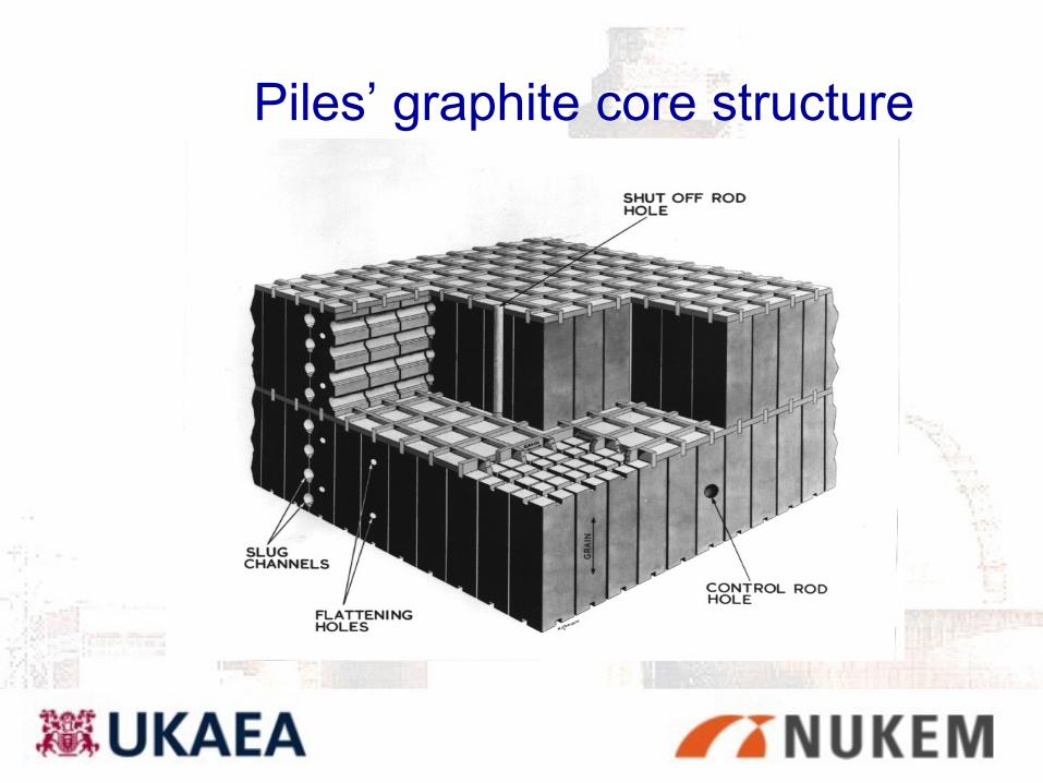
Piles’ graphite core structure
UK graphites/1
There are four main sources of UK Graphite: – UKAEA, Windscale Piles, BEPO, GLEEP and various
research reactors. Types AGXP, AGX, Welland etc. Grades A, B and C depending on the quality
• manufactured from refining coke from Sarnia Canada obtained from Alberta oilfields
– Magnox, Pile Grade A (PGA) and Pile Grade B (PGB) found in various grades
– AGR Moderator Gilsocarbon and Reflector manufactured from various isotropic graphites
• Gilsocarbon purity less than PGA, particular concerns with 59Co60Co
– Magnox and AGR Sleeves, PGA (Magnox) and various pitch coke graphites respectively
UK Graphites/2
Piles, AGXP, PGA(Magnox) graphites:
– Petroleum coke, by-product of oil refining process.
– Needle-shaped coke particles.
– Extrusion process aligns coke particles.
– Crystallographic layer planes tend to lie parallel to
extrusion axis.
– Graphite properties are anisotropic
Early Decommissioning, Phase I - securing the safety of the facility
• Commenced early 1980’s
– Sealing of bioshield
– Installation of ventilation and monitoring
– Loose fuel removal from outside core
– Drain-down of water duct
– Core removal option studies
– Completed June 1999

Air Duct Clearance
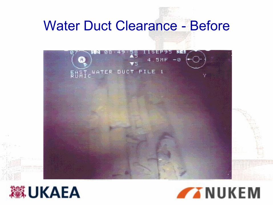
Water Duct Clearance - Before
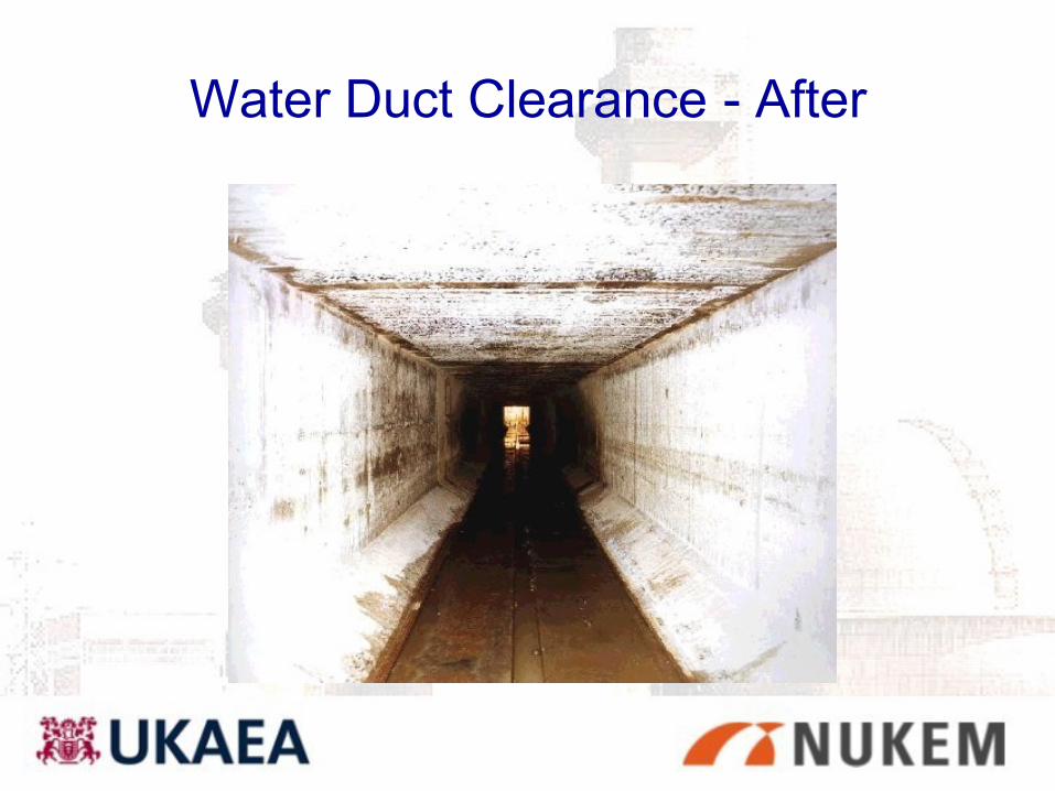
Water Duct Clearance - After
Present condition of Pile 1
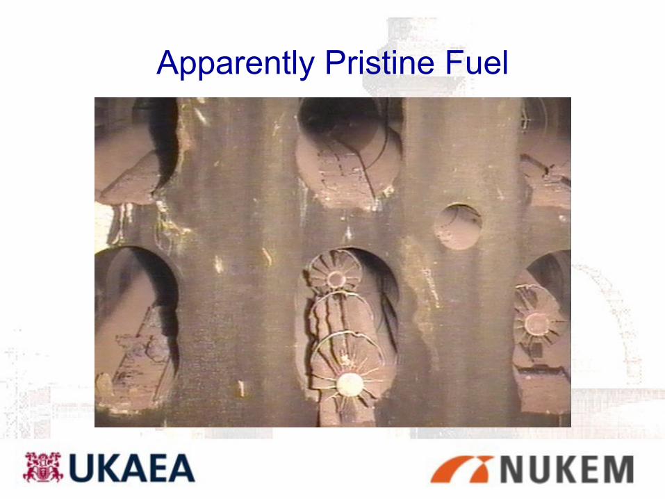
Apparently Pristine Fuel
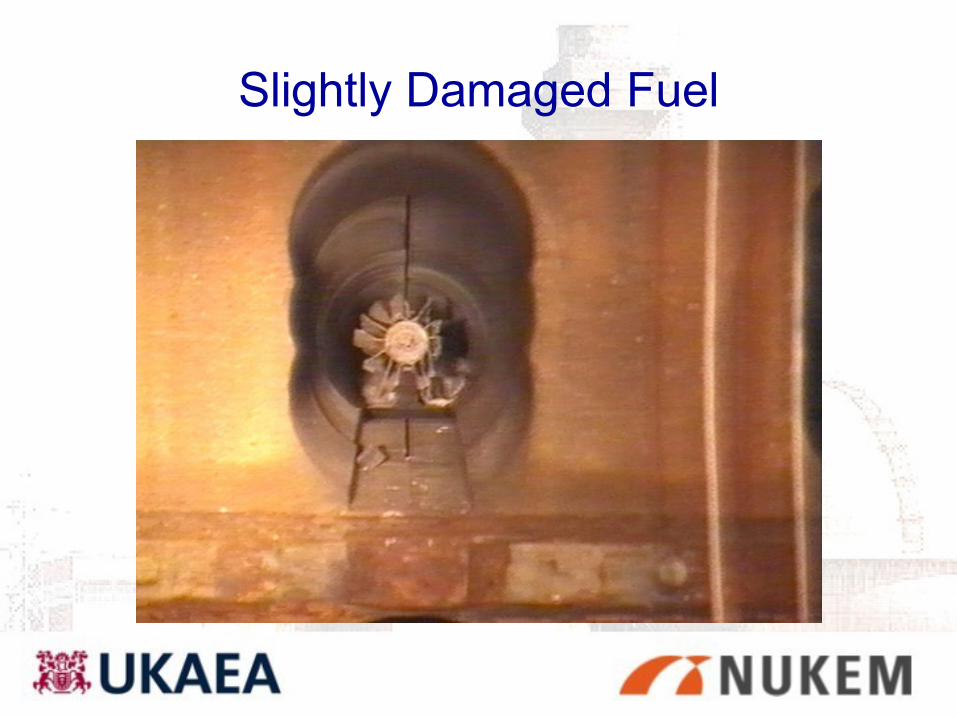
Slightly Damaged Fuel

Destroyed Fuel - 23.54
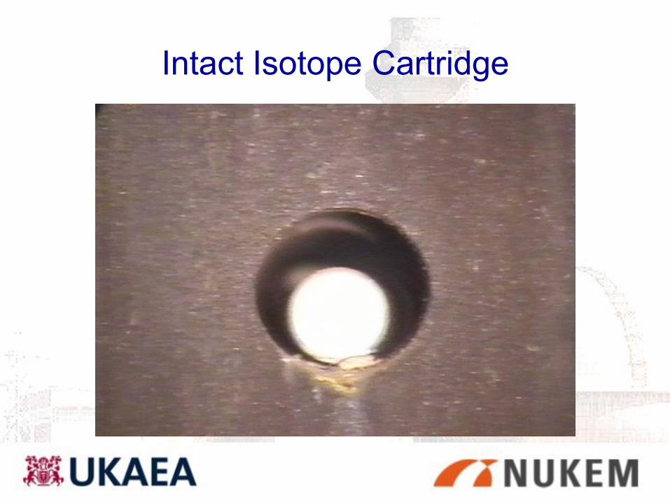
Intact Isotope Cartridge
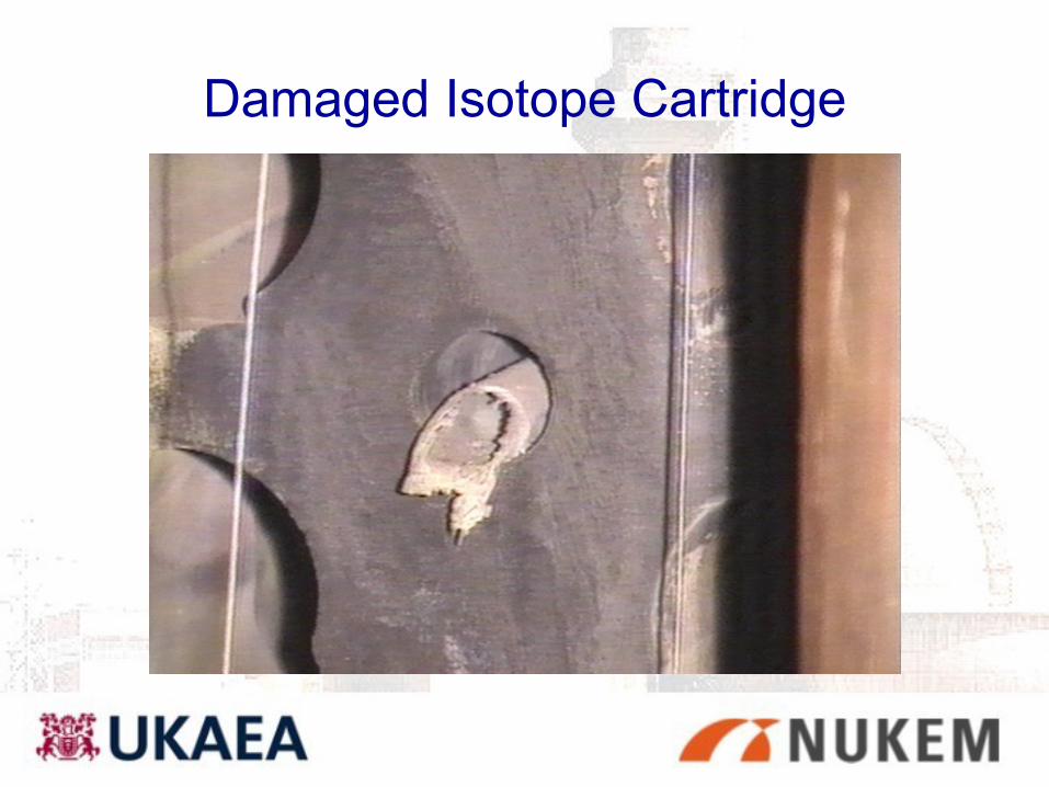
Damaged Isotope Cartridge
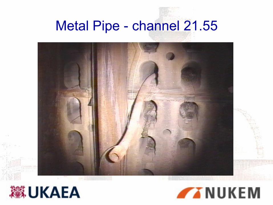
Metal Pipe - channel 21.55
Hazards and
decommissioning issues

Pile 1 safety issues for decommissioning
• ~15 te fuel still present
• Possible core voidage post ‘57 fire - seismic collapse is Design Basis Accident under C&M
• Characterisation issues:– Wigner energy in graphite
– ‘hydride event’ (pyrophoric material present?)
– graphite dust explosion?
– Criticality?
Characterisation issues dominate - no intrusive FAZ survey at present. Physical characterisation dominates.

Hazards - Wigner energy
• Pile was left partially unannealed in ‘57
• Extent of anneal is unknown
• WE will be greatest nearer cooler charge face and core
edges in high flux regions
• WE is principally issue for waste disposal
• Pile 1 accumulated ~3 times more neutron dose than
Pile 2 (4.1 x 10⁴MWd cf Pile 2, 1.5 x 10⁴MWd)
Only route forward for WE determination is physical
sampling!
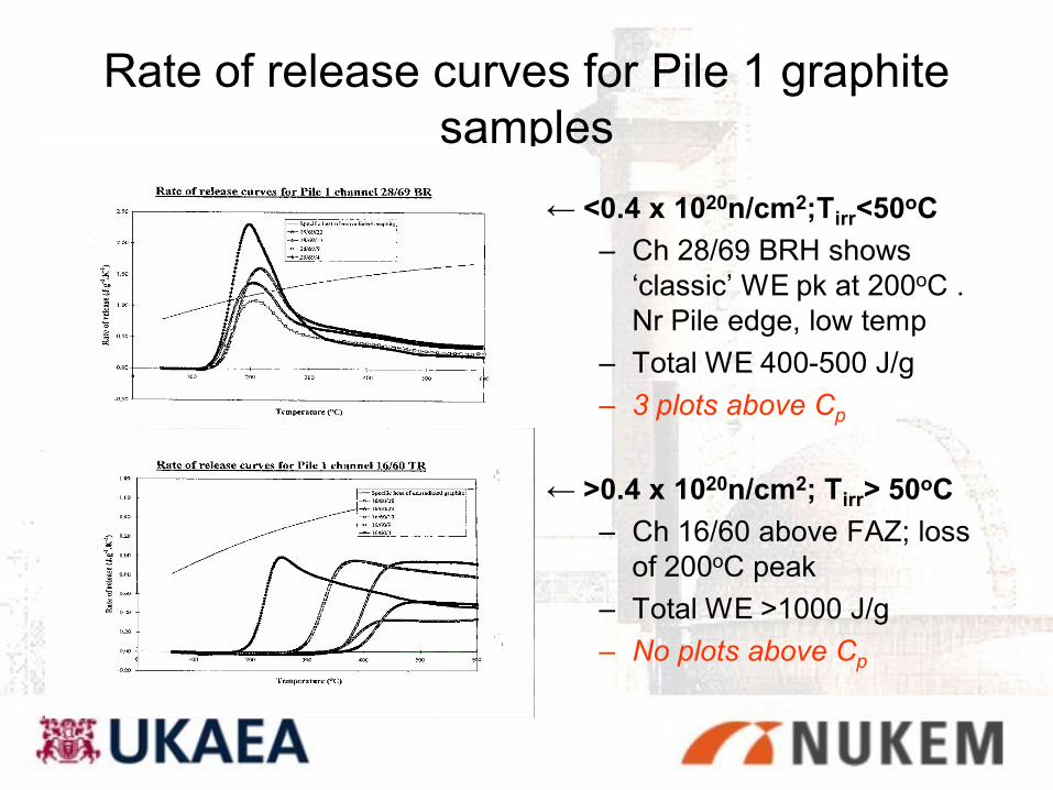
Rate of release curves for Pile 1 graphite
samples
← <0.4 x 10²⁰n/cm2;Tirr<50oC
– Ch 28/69 BRH shows
‘classic’ WE pk at 200oC .
Nr Pile edge, low temp
– Total WE 400-500 J/g
– 3 plots above Cp
← >0.4 x 10²⁰n/cm2; Tirr> 50oC
– Ch 16/60 above FAZ; loss
of 200oC peak
– Total WE >1000 J/g
– No plots above Cp
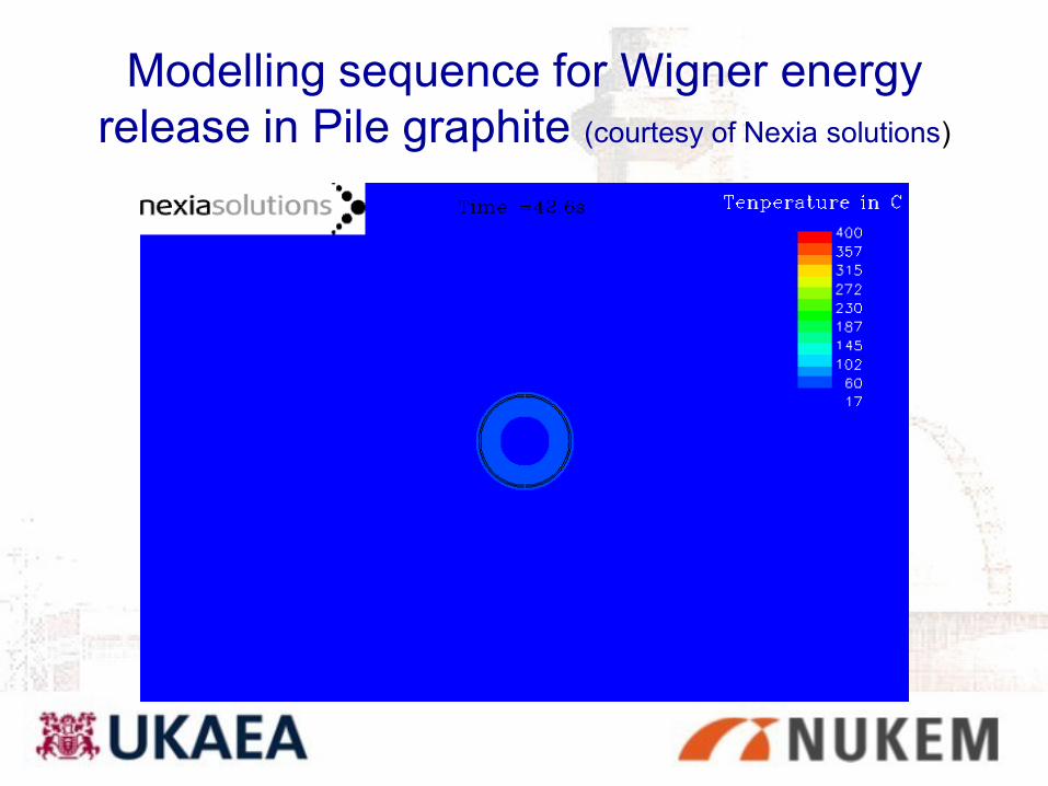
Modelling sequence for Wigner energy
release in Pile graphite (courtesy of Nexia solutions)
Results of trepanned graphite samples from
Pile 1
Pile 1 had ~3 time the dose of Pile 2 (4.15 x10⁴ MWd)
• Density; 3% wt. loss (1.58 cf 1.63g/cm3); radiolytic
oxidation
• Wigner energy; up to 1220 J/g
• Thermal conductivity; min 2.1 W. m-1.K-1 cf 100 - 200 W.
m-1.K-1 ┴ and ║ to extrusion direction
• Thermal oxidation rate at 637 K – high variability; 30-700
μg.g-1.h-1, mean 760 μg.g-1.h-1; isolated results to 7405
μg.g-1.h-1 Catalytic effects probably Pb.

Results of trepanned graphite samples from
Pile 2
• Density; 3% wt. loss (1.58 cf 1.63g/cm3); radiolytic
oxidation
• Wigner energy; up to 1060 J/g
• Thermal conductivity; min 2.3 W. m-1.K-1
• Thermal oxidation rate at 637 K – high variability; 30-700
μg.g-1.h-1 isolated results to 10767 μg.g-1.h-1. Catalytic
effects.
Strategy for graphite waste managementKey Points:
•Disposal as ILW in standard Nirex 4m box
•Not annealing graphite
•Not encapsulating graphite in cement for interim
storage
•Intent to demonstrate safety during interim storage,
transport and final disposal in National ILW repository
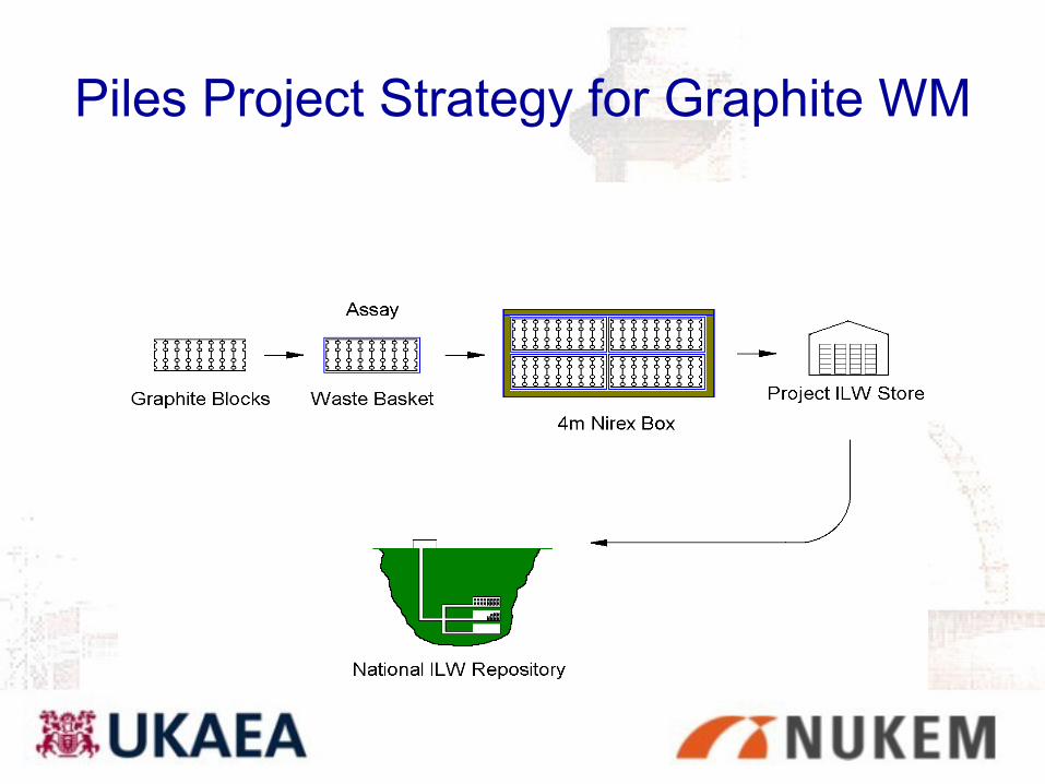
Piles Project Strategy for Graphite WM
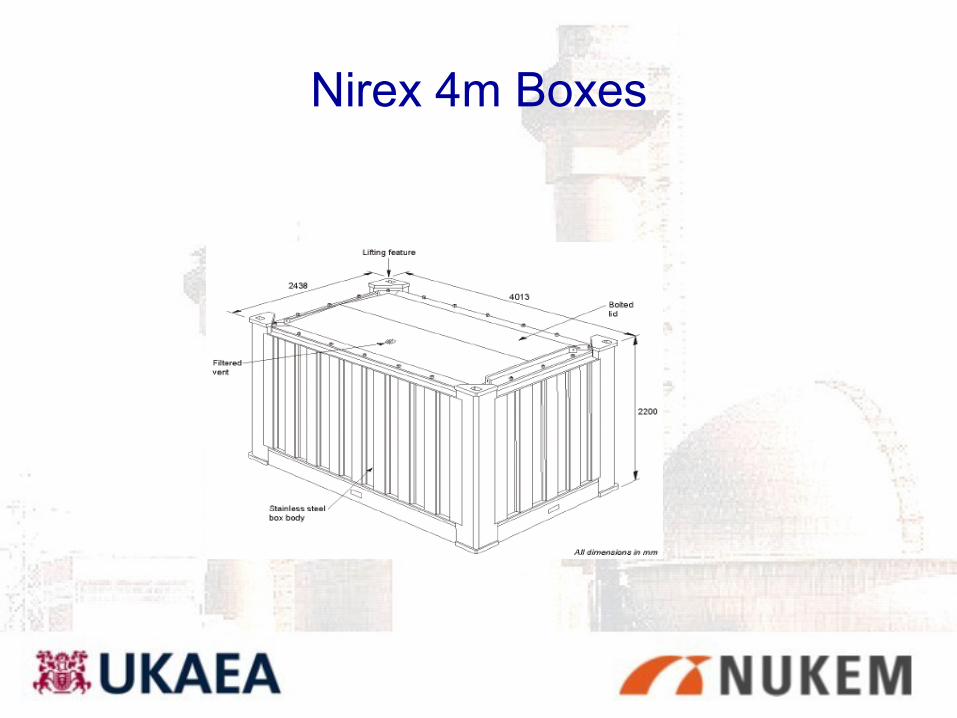
Nirex 4m Boxes
Key Issues for graphite waste
packaging•Dust (mainly oxidation products)
•Graphite flotation (if encapsulated later)
•Galvanic corrosion (acts as ‘noble’ metal, galvanic
corrosion)
•Wigner energy
Wigner Energy issues
Issue – stored energy could be released during grouting
of the National ILW repository causing heat release
which could damage the integrity of the wasteform
and/or backfill.
Intent - To work with Nirex in modelling the behaviour of
the repository and graphite boxes during grouting in
order to :
•Understand the causes and effects
•Quantify the risks – impacts and probabilities
•Reduction of key risks e.g. exploring backfilling
scenarios
Hazards - pyrophoric materials
• Uranium hydride is the only pyrophoric material conjectured to be
a hazard in the Pile (from thermodynamic considerations)
• Water used during ‘57 fire to extinguish and remove heat
• UH3 unlikely to have formed but cannot be ruled out:
– anaerobic pockets, ‘crimped’ fuel cans from rodding
– for safety argument purposes some is assumed to exist
• Recent published work has improved our understanding of hydride
oxidation kinetics. New approach being taken:
– Use of CFD modelling
– Combination of CFD with oxidation kinetics to produce a
‘thermal model’
– Simulation of probable Pile 1 scenarios
Uranium Reactivity
• U metal reacts with oxygen in air → UO2+x
• U metal reacts with water vapour → UH3
• In Pile 1 conditions UH3 would not form (air)
• In Pile 1 conditions UH3 would not survive
unless in microclimate situation – unlikely, but
cannot ‘prove a negative’
Hence we have pessimistically assumed that the presence
of some UH3 cannot be ruled out for safety case
purposes!
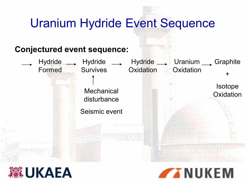
Uranium Hydride Event Sequence
Conjectured event sequence:
Hydride
Formed
Hydride
Survives
Hydride
Oxidation
Uranium
Oxidation
Graphite
+
Isotope
OxidationMechanical
disturbance
Seismic event

Fuel element condition - gross
corrosion, Channel 21, 58
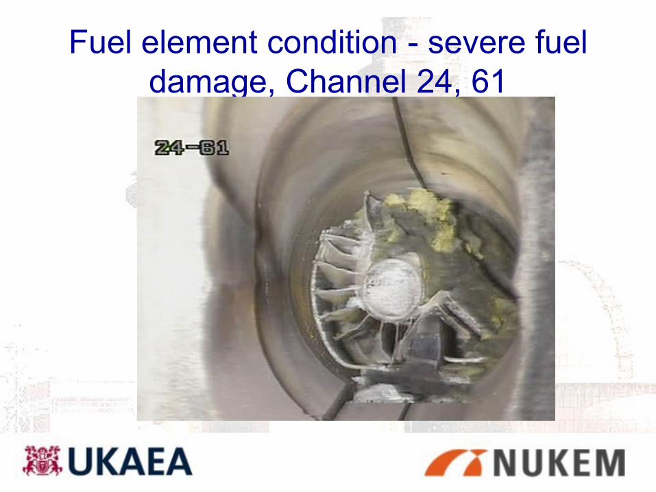
Fuel element condition - severe fuel
damage, Channel 24, 61
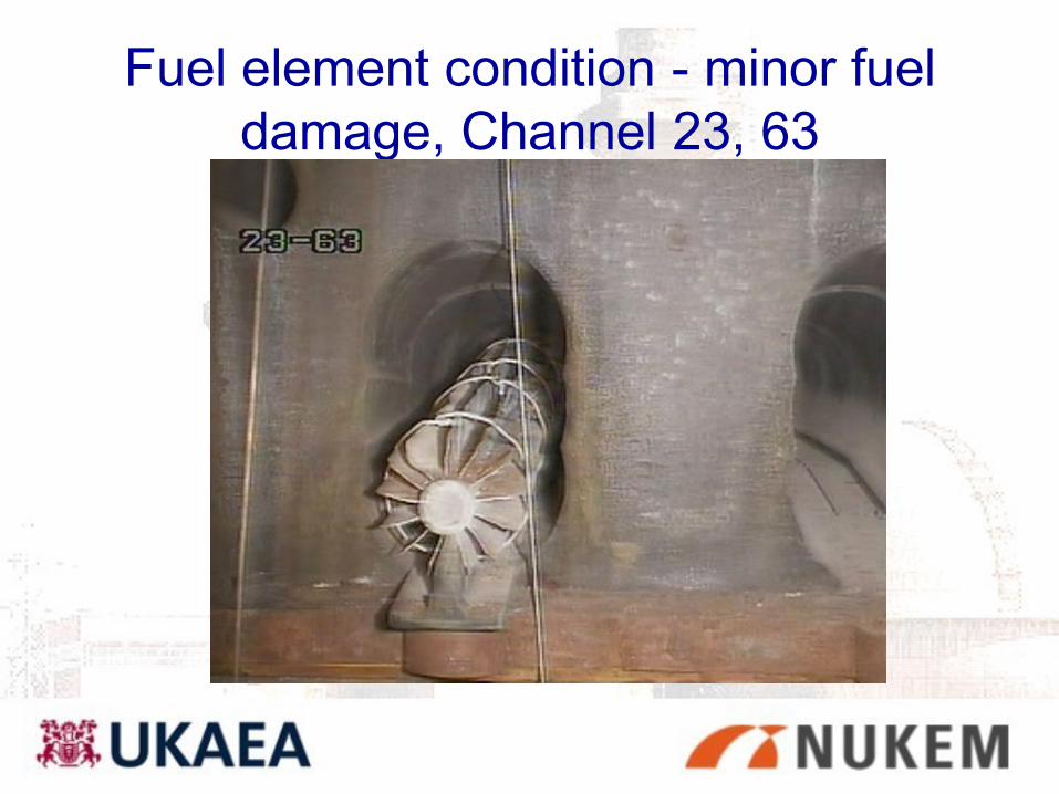
Fuel element condition - minor fuel
damage, Channel 23, 63
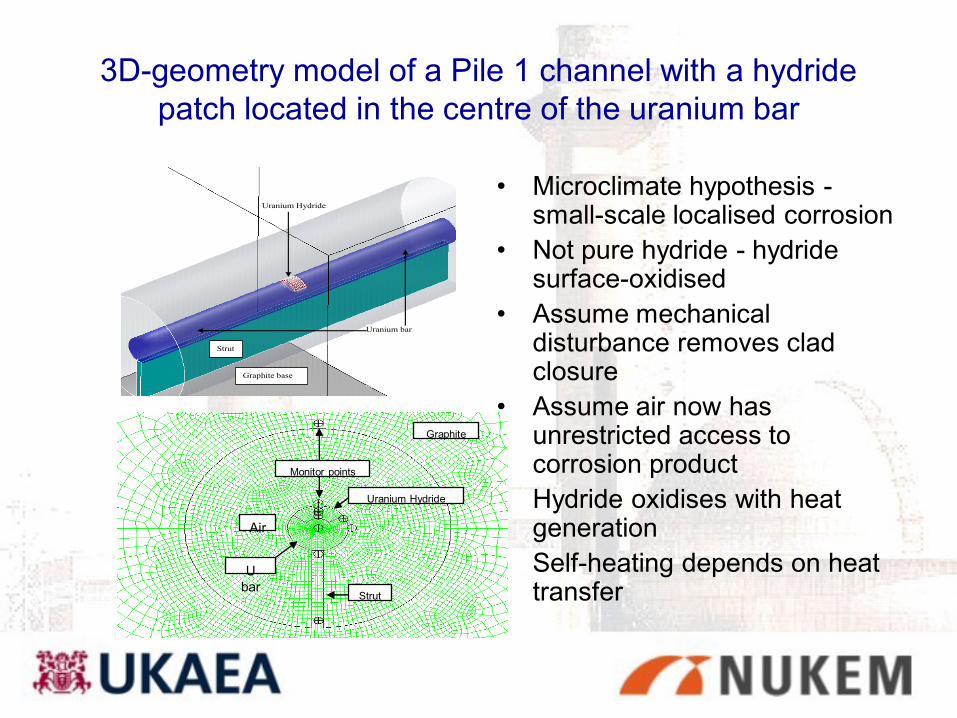
3D-geometry model of a Pile 1 channel with a hydride
patch located in the centre of the uranium bar
• Microclimate hypothesis -small-scale localised corrosion
• Not pure hydride - hydride surface-oxidised
• Assume mechanical disturbance removes clad closure
• Assume air now has unrestricted access to corrosion product
• Hydride oxidises with heat generation
• Self-heating depends on heat transfer
Uranium Hydride
Uranium bar
Strut
Graphite base
Graphite
Air
Uranium Hydride
Monitor points
Strut
U
bar
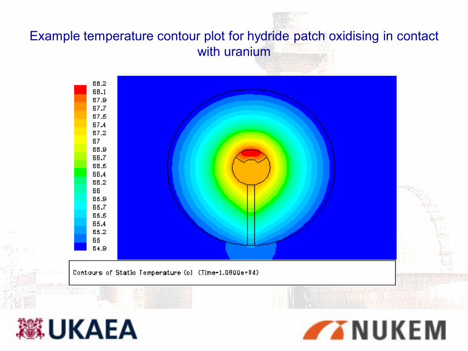
Example temperature contour plot for hydride patch oxidising in contact
with uranium
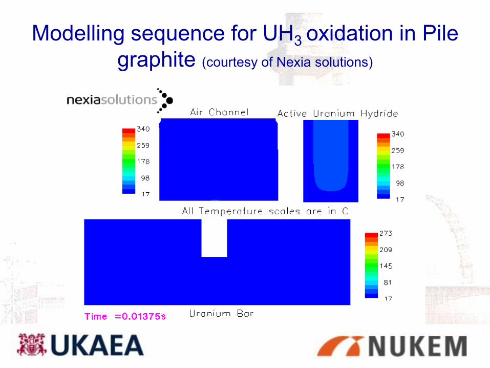
Modelling sequence for UH3 oxidation in Pile
graphite (courtesy of Nexia solutions)
Lessons learned for Pile 1
Conjectured surviving hydride will not self-heat to give a
propagating thermal excursion if exposed to air:
– Bulk U metal will not be heated enough to oxidise significantly
– Temp. rise so small - no WE release in neighbouring graphite
– Isotope cartridges remain unaffected; no cross-channel effects
– Effects of hydrogen liberation are insignificant
Argon cover will not be required during
dismantling
Hazards - graphite dust explosibility
• Controversy has existed over the potential for a graphite dust
explosion during decommissioning (UK, France, Italy, Japan)
• Graphite dust when levitated in sufficient concentration, with
appropriate particle size and high energy input is weakly explosible
• Lead (Pb) is known to enhance graphite oxidation markedly – lead
cartridges in Piles
• For safety case purposes some quantitative data was required –
research programmes have now been conducted
–

Graphite dust ‘explosions’ - general
principlesTo have a dust explosion, you must simultaneously
have:• A combustible dust
• An ignition source of sufficient energy
• An atmosphere capable of supporting combustion
• Suspended dust (turbulence or disturbance of deposits);
• A concentration within the ‘explosible range’
• A particle-size distribution which permits flame propagation.
For a disruptive incident to occur you must also have:
• Confinement

Important Parameters
• Maximum rate of rise in pressure (measured as
‘deflagration index’ Kst) – delivers an impulsive load to
the system
• Maximum explosion pressure attained
• Minimum ignition energy
• Minimum explosible concentration
• Auto-ignition temperature for deposited dusts.
Nuclear grade graphite dust is now formally
classified as “weakly explosible” [St1]
(based upon the ISO test which uses a powerful
chemical igniter)
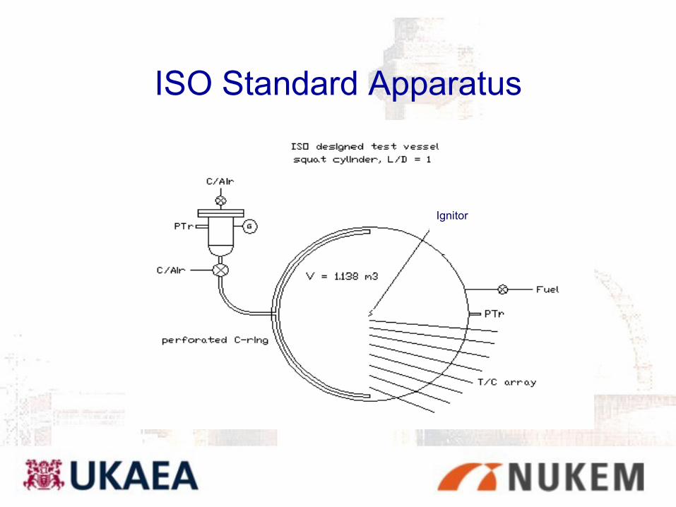
ISO Standard Apparatus
Ignitor
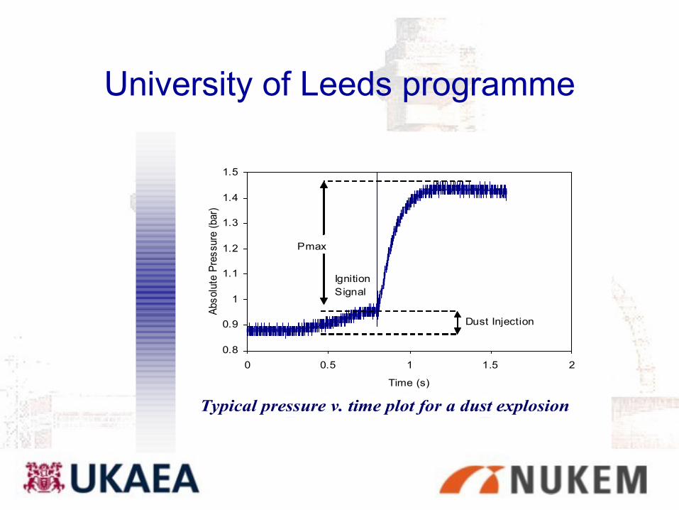
University of Leeds programme
0.8
0.9
1
1.1
1.2
1.3
1.4
1.5
0 0.5 1 1.5 2
Time (s)
Abs
olu
te P
res
sure
(bar)
Ignition
Signal
Pmax
Dust Injection
Typical pressure v. time plot for a dust explosion

Overpressure due to Graphite alone
1
1.1
1.2
1.3
1.4
0.8 0.85 0.9 0.95 1
Time, s
Pre
ssu
re,
ba
ra
500
400
300
227
114
ISO rig
Graphite only
mass of graphite (g)
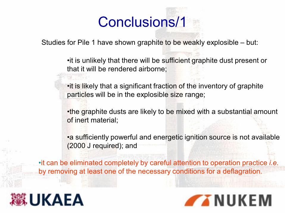
Conclusions/1
Studies for Pile 1 have shown graphite to be weakly explosible – but:
•it is unlikely that there will be sufficient graphite dust present or
that it will be rendered airborne;
•it is likely that a significant fraction of the inventory of graphite
particles will be in the explosible size range;
•the graphite dusts are likely to be mixed with a substantial amount
of inert material;
•a sufficiently powerful and energetic ignition source is not available
(2000 J required); and
•it can be eliminated completely by careful attention to operation practice i.e.
by removing at least one of the necessary conditions for a deflagration.
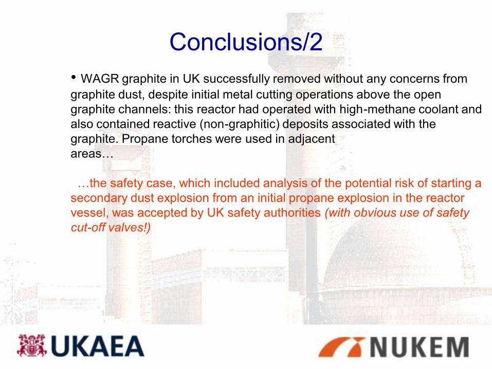
Conclusions/2
• WAGR graphite in UK successfully removed without any concerns from
graphite dust, despite initial metal cutting operations above the open
graphite channels: this reactor had operated with high-methane coolant and
also contained reactive (non-graphitic) deposits associated with the
graphite. Propane torches were used in adjacent
areas…
…the safety case, which included analysis of the potential risk of starting a
secondary dust explosion from an initial propane explosion in the reactor
vessel, was accepted by UK safety authorities (with obvious use of safety
cut-off valves!)

Hazards – remaining fissile content of
Pile 1
• Estimation of effective neutron multiplication factor, keff
is required for criticality safety analysis:
– to plan dismantling
– under accident conditions (seismic)
– Quantitative estimate of reactivity required since 15
te U is sufficient for a criticality (Li cartridges
suppressing reactivity)
– a combination of modelling codes (MONK, MCNP)
and direct neutron flux measurements used
Pile 1 fissile content - results
• Direct neutron measurements showed improved
criticality margin over value estimated by MONK calcs
(6% less)
• Indication that less fuel present than previously thought
• Safety report demonstrated that criticality margin is
preserved during DBA (seismic core collapse)

Conclusions on decommissioning issues
• Pile 1 presents some particularly difficult decommissioning problems with unique issues
• Situation will be improved by ability to remove samples from fire-damaged area
• Progress has been made on several fronts:– Visual inspection via CCTV
– Better understanding of the Wigner energy levels in graphite
– Uranium Hydride
• pessimistic analysis shows oxidation transient will not propagate
• can dismantle in air
– Graphite dust explosions can be dismissed
– Criticality - no problems during a seismic event providing neutron absorbing material remains
• no additional N absorber needed
• sequenced removal of material during dismantling