Embed Size (px)
Citation preview
8/3/2019 Wind Generation System
http://slidepdf.com/reader/full/wind-generation-system 1/9
IEEE TRANSACTIONS ON POWER ELECTRONICS, VOL. 12, NO. 1, JANUARY 1997 87
Fuzzy Logic Based Intelligent Control of a VariableSpeed Cage Machine Wind Generation System
Marcelo Godoy Simoes, Member, IEEE, Bimal K. Bose, Life Fellow, IEEE, and Ronald J. Spiegel, Member, IEEE
Abstract—The paper describes a variable speed wind genera-tion system where fuzzy logic principles are used for efficiencyoptimization and performance enhancement control. A squirrelcage induction generator feeds the power to a double-sided pulsewidth modulated converter system which pumps power to a utilitygrid or can supply to an autonomous system. The generationsystem has fuzzy logic control with vector control in the innerloops. A fuzzy controller tracks the generator speed with the windvelocity to extract the maximum power. A second fuzzy controllerprograms the machine flux for light load efficiency improvement,and a third fuzzy controller gives robust speed control againstwind gust and turbine oscillatory torque. The complete control
system has been developed, analyzed, and validated by simulationstudy. Performances have then been evaluated in detail.
I. INTRODUCTION
AWIND electrical generation system is the most cost-
competitive of all the environmentally clean and safe
renewable energy sources in the world. It is also competitive
with fossil fuel generated power and much cheaper than
nuclear power. Although the history of wind power goes back
more than two centuries, its potential to generate electrical
power began to get attention from the beginning of this
century. However, during the last two decades, wind power has
been seriously considered to supplement the power generationby fossil fuel and nuclear methods. In recent years, wind
power is gaining more acceptance because of environmental
and safety problems of conventional power plants and ad-
vancement of wind electric generation technology. The world
has enormous resources of wind power. It has been estimated
that even if 10% of raw wind potential could be put to
use, all the electricity needs of the world would be met
[1]. There are currently over 1700 MW of wind generators
installed worldwide with generation of 6 billion kWh of energy
annually. It has been estimated the generation will grow to 60
billion kWh by the year 2000. Of course, the main drawback
of wind power is that its availability is somewhat statistical
in nature and must be supplemented by additional sources tosupply the demand curve.
Manuscript received August 29, 1995; revised May 30, 1996.M. G. Simoes is with the University of S ~ ao Paulo, S~ ao Paulo 05508-900
Brazil.B. K. Bose is with the Department of Electrical Engineering, The University
of Tennessee, Knoxville, TN 37996 USA.R. J. Spiegel is with the Air and Energy Engineering Research Laboratory,
U.S. Environmental Protection Agency, Research Triangle Park, NC 27711USA.
Publisher Item Identifier S 0885-8993(97)00621-2.
Traditionally, wind generation systems used variable pitch
constant speed wind turbines (horizontal or vertical axis)
that were coupled to squirrel cage induction generators or
wound-field synchronous generators and fed power to utility
grids or autonomous loads. The recent evolution of power
semiconductors and variable frequency drives technology has
aided the acceptance of variable speed generation systems. In
spite of the additional cost of power electronics and control, the
total energy capture in a variable speed wind turbine (VSWT)
system is larger and, therefore, the life-cycle cost is lower. The
following generator-converter systems have been popularlyused [2]–[4]:
• doubly fed induction generator with cascaded converter
slip power recovery;
• doubly fed induction generator with cycloconverter slip
power recovery;
• synchronous generator with line-commutated and load-
commutated thyristor converters.
In addition to the above schemes, squirrel cage generators
with shunt passive or active VAR (volt ampere reactive)
generators [5], [6] have been proposed which generate constant
voltage constant frequency power through a diode rectifierand line-commutated thyristor inverter. Recently, a variable
reluctance machine [7] and doubly stator-fed induction ma-
chine [8] have also been proposed in wind generation systems.
The major problems in traditional power conversion schemes
are the poor line power factor and harmonic distortion in
line and machine currents. The recent IEEE Standard 519
[9] severely restricts line harmonic injection. Therefore, to
satisfy the stringent harmonic standard and poor power factor
problem, active type VAR and harmonic compensators can be
installed at additional cost. Again, the conventional control
principles used in these systems make the response sluggish
and give nonoptimum performance. Very recently, a double-sided pulse width modulated (PWM) converter system has
been proposed to overcome some of the above problems.
This paper, a complete simulation study to validate the
theoretical concepts (the experimental work is in progress
and will be reported later), describes a VSWT system with
a squirrel cage induction generator and a double-sided PWM
converter where fuzzy logic control has been used extensively
to maximize the power output and enhance system perfor-
mance. All the control algorithms have been validated by
simulation study and system performance has been evaluated
0885–8993/97$10.00 © 1997 IEEE
8/3/2019 Wind Generation System
http://slidepdf.com/reader/full/wind-generation-system 2/9
88 IEEE TRANSACTIONS ON POWER ELECTRONICS, VOL. 12, NO. 1, JANUARY 1997
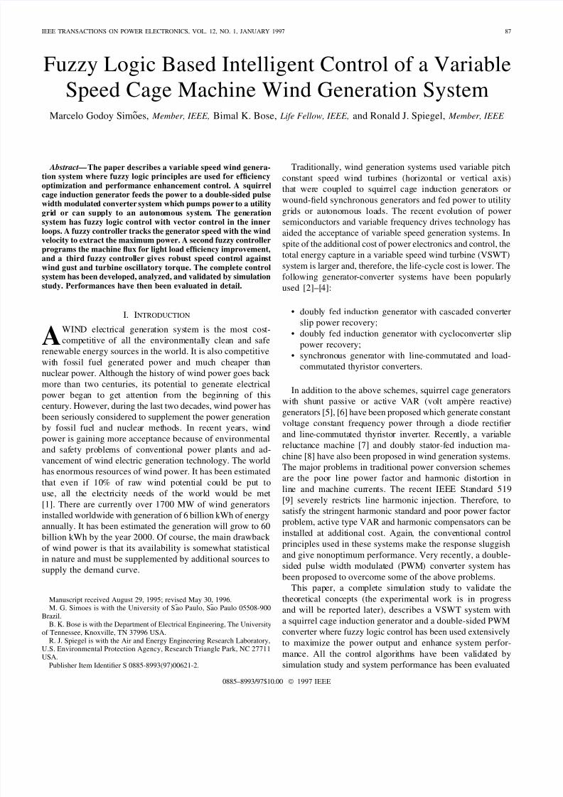
Fig. 1. A voltage-fed double PWM converter wind generation system.
in detail. An experimental study with a 3.5-kW-laboratory
drive system is in progress. It will eventually be transitioned
into a 200-kW prototype generation system.
II. WIND GENERATION SYSTEM DESCRIPTION
A. Converter System
The voltage-fed converter scheme used in this system is
shown in Fig. 1. A vertical (or horizontal) wind turbine is
coupled to the shaft of a squirrel cage induction generator
through a speedup gear ratio (not shown). The variable fre-
quency variable voltage power from the generator is rectified
by a PWM IGBT (insulated gate bipolar transistor) rectifier.
The rectifier also supplies the excitation need of the machine.
The inverter topology is identical to that of the rectifier,
and it supplies the generated power at 60 Hz to the utility
grid. Salient advantages of the converter system include the
following.
• Line side power factor is unity with no harmonic current
injection (satisfies IEEE 519).
• The cage type induction machine is extremely rugged,
reliable, economical, and universally popular.
• Machine current is sinusoidal—no harmonic copper loss.
• Rectifier can generate programmable excitation for the
machine.
• Continuous power generation from zero to highest turbine
speed is possible.
• Power can flow in either direction permitting the gener-
ator to run as a motor for start-up (required for vertical
turbine). Similarly, regenerative braking can quickly stopthe turbine.
• Autonomous operation of the system is possible with
either a start-up capacitor or with a battery on the dc link.
• Extremely fast transient response is possible.
• Multiple generators or multiple systems can be operated
in parallel.
• The inverter can be operated as a VAR/harmonic com-
pensator when spare capacity is available.
Considering all the above advantages, and with the present
trend of decreasing converter and control cost, this type of
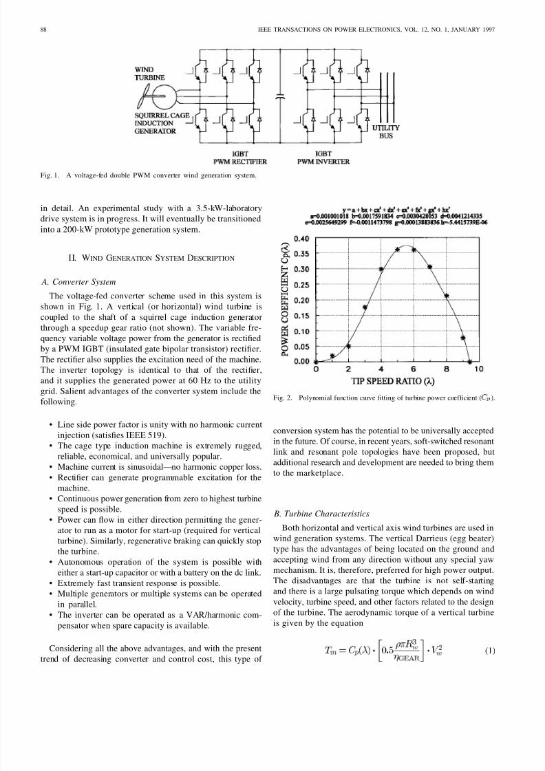
Fig. 2. Polynomial function curve fitting of turbine power coefficient ( C
p
).
conversion system has the potential to be universally accepted
in the future. Of course, in recent years, soft-switched resonant
link and resonant pole topologies have been proposed, but
additional research and development are needed to bring them
to the marketplace.
B. Turbine Characteristics
Both horizontal and vertical axis wind turbines are used in
wind generation systems. The vertical Darrieus (egg beater)type has the advantages of being located on the ground and
accepting wind from any direction without any special yaw
mechanism. It is, therefore, preferred for high power output.
The disadvantages are that the turbine is not self-starting
and there is a large pulsating torque which depends on wind
velocity, turbine speed, and other factors related to the design
of the turbine. The aerodynamic torque of a vertical turbine
is given by the equation
(1)
8/3/2019 Wind Generation System
http://slidepdf.com/reader/full/wind-generation-system 3/9
SIMOES et al.: FUZZY LOGIC BASED INTELLIGENT CONTROL OF A WIND GENERATION SYSTEM 89
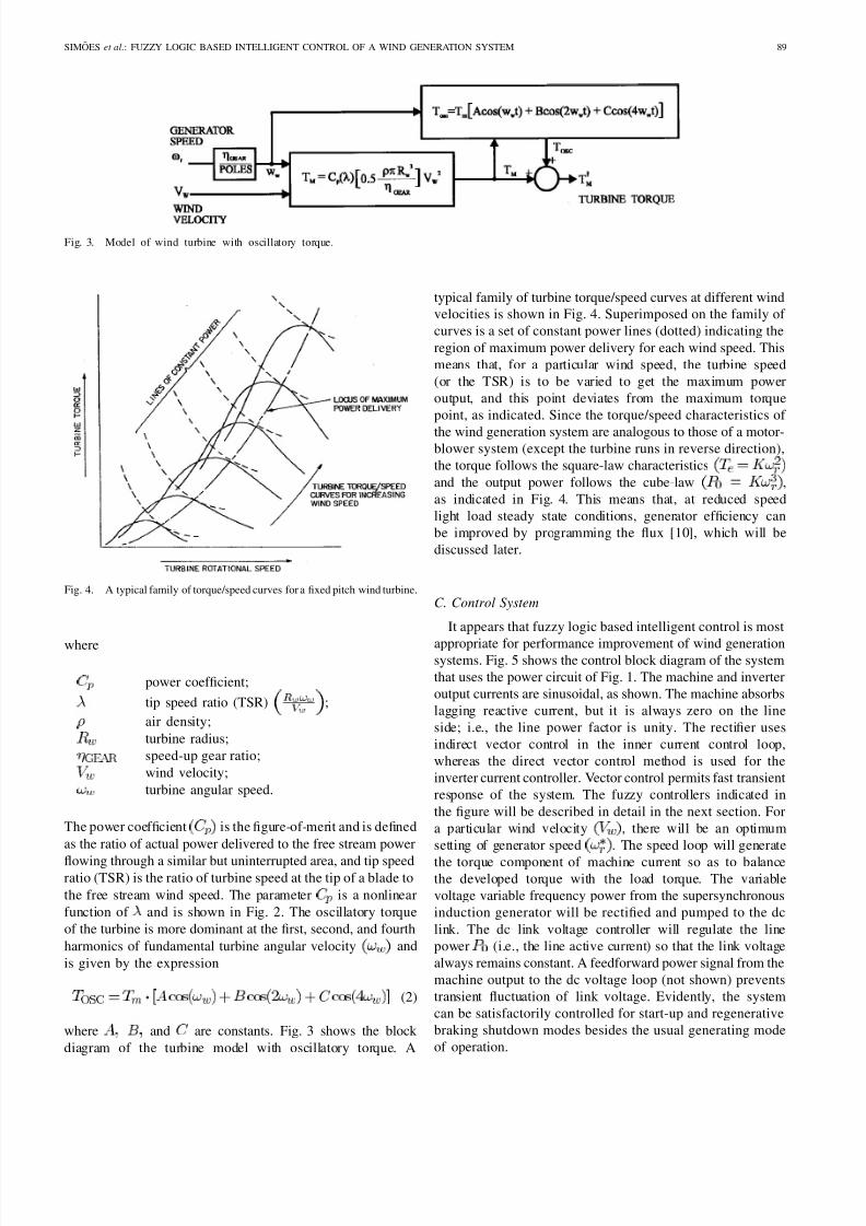
Fig. 3. Model of wind turbine with oscillatory torque.
Fig. 4. A typical family of torque/speed curves for a fixed pitch wind turbine.
where
power coefficient;
tip speed ratio (TSR) ;
air density;
turbine radius;
speed-up gear ratio;
wind velocity;
turbine angular speed.
The power coefficient is the figure-of-merit and is defined
as the ratio of actual power delivered to the free stream power
flowing through a similar but uninterrupted area, and tip speedratio (TSR) is the ratio of turbine speed at the tip of a blade to
the free stream wind speed. The parameter is a nonlinear
function of and is shown in Fig. 2. The oscillatory torque
of the turbine is more dominant at the first, second, and fourth
harmonics of fundamental turbine angular velocity and
is given by the expression
(2)
where and are constants. Fig. 3 shows the block
diagram of the turbine model with oscillatory torque. A
typical family of turbine torque/speed curves at different windvelocities is shown in Fig. 4. Superimposed on the family of
curves is a set of constant power lines (dotted) indicating the
region of maximum power delivery for each wind speed. This
means that, for a particular wind speed, the turbine speed
(or the TSR) is to be varied to get the maximum power
output, and this point deviates from the maximum torque
point, as indicated. Since the torque/speed characteristics of
the wind generation system are analogous to those of a motor-blower system (except the turbine runs in reverse direction),
the torque follows the square-law characteristics
and the output power follows the cube-law ,
as indicated in Fig. 4. This means that, at reduced speed
light load steady state conditions, generator efficiency can
be improved by programming the flux [10], which will be
discussed later.
C. Control System
It appears that fuzzy logic based intelligent control is most
appropriate for performance improvement of wind generationsystems. Fig. 5 shows the control block diagram of the system
that uses the power circuit of Fig. 1. The machine and inverter
output currents are sinusoidal, as shown. The machine absorbs
lagging reactive current, but it is always zero on the line
side; i.e., the line power factor is unity. The rectifier uses
indirect vector control in the inner current control loop,
whereas the direct vector control method is used for the
inverter current controller. Vector control permits fast transient
response of the system. The fuzzy controllers indicated in
the figure will be described in detail in the next section. For
a particular wind velocity , there will be an optimum
setting of generator speed . The speed loop will generate
the torque component of machine current so as to balancethe developed torque with the load torque. The variable
voltage variable frequency power from the supersynchronous
induction generator will be rectified and pumped to the dc
link. The dc link voltage controller will regulate the line
power (i.e., the line active current) so that the link voltage
always remains constant. A feedforward power signal from the
machine output to the dc voltage loop (not shown) prevents
transient fluctuation of link voltage. Evidently, the system
can be satisfactorily controlled for start-up and regenerative
braking shutdown modes besides the usual generating mode
of operation.
8/3/2019 Wind Generation System
http://slidepdf.com/reader/full/wind-generation-system 4/9
90 IEEE TRANSACTIONS ON POWER ELECTRONICS, VOL. 12, NO. 1, JANUARY 1997
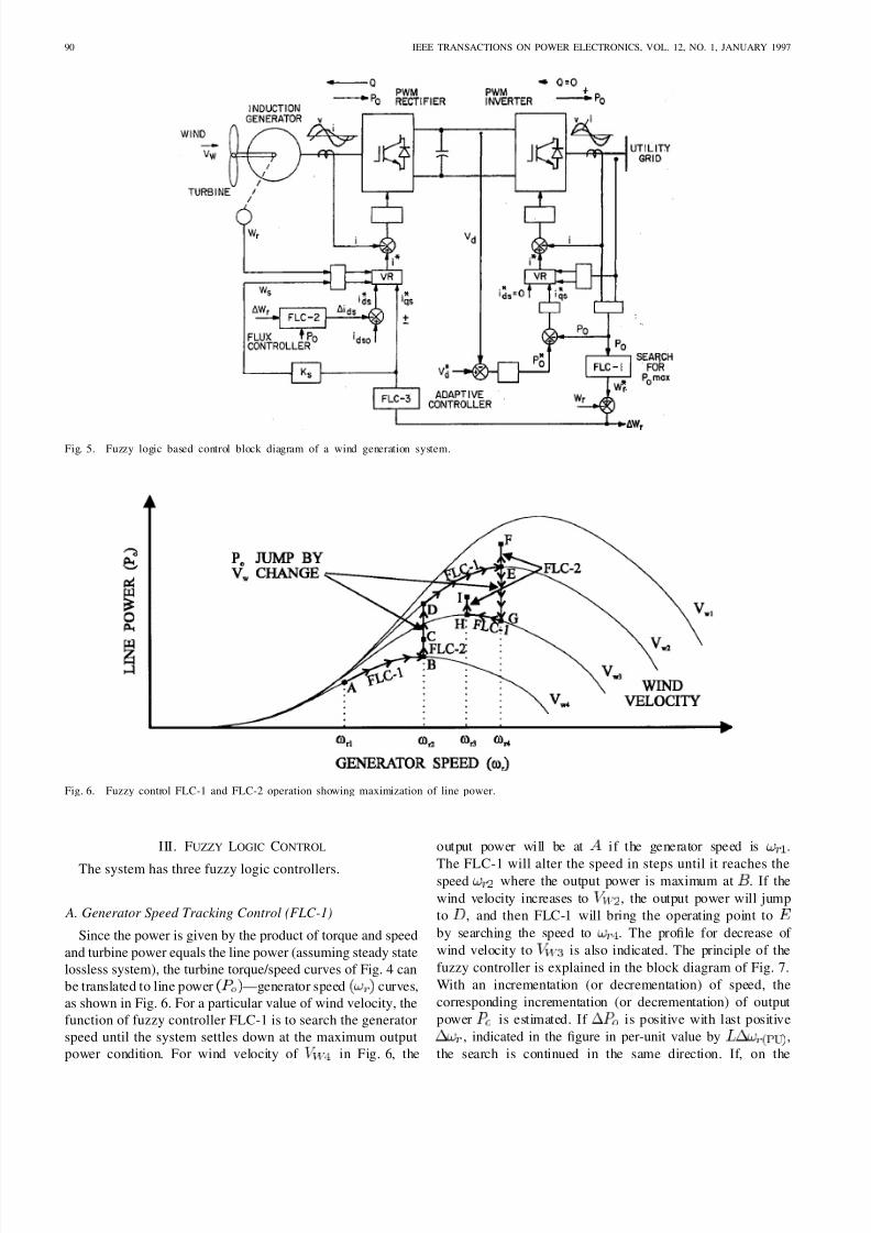
Fig. 5. Fuzzy logic based control block diagram of a wind generation system.
Fig. 6. Fuzzy control FLC-1 and FLC-2 operation showing maximization of line power.
III. FUZZY LOGIC CONTROL
The system has three fuzzy logic controllers.
A. Generator Speed Tracking Control (FLC-1)
Since the power is given by the product of torque and speed
and turbine power equals the line power (assuming steady state
lossless system), the turbine torque/speed curves of Fig. 4 can
be translated to line power —generator speed curves,
as shown in Fig. 6. For a particular value of wind velocity, the
function of fuzzy controller FLC-1 is to search the generator
speed until the system settles down at the maximum output
power condition. For wind velocity of in Fig. 6, the
output power will be at if the generator speed is .
The FLC-1 will alter the speed in steps until it reaches thespeed where the output power is maximum at . If the
wind velocity increases to , the output power will jump
to , and then FLC-1 will bring the operating point to
by searching the speed to . The profile for decrease of
wind velocity to is also indicated. The principle of the
fuzzy controller is explained in the block diagram of Fig. 7.
With an incrementation (or decrementation) of speed, the
corresponding incrementation (or decrementation) of output
power is estimated. If is positive with last positive
, indicated in the figure in per-unit value by ,
the search is continued in the same direction. If, on the
8/3/2019 Wind Generation System
http://slidepdf.com/reader/full/wind-generation-system 5/9
SIMOES et al.: FUZZY LOGIC BASED INTELLIGENT CONTROL OF A WIND GENERATION SYSTEM 91
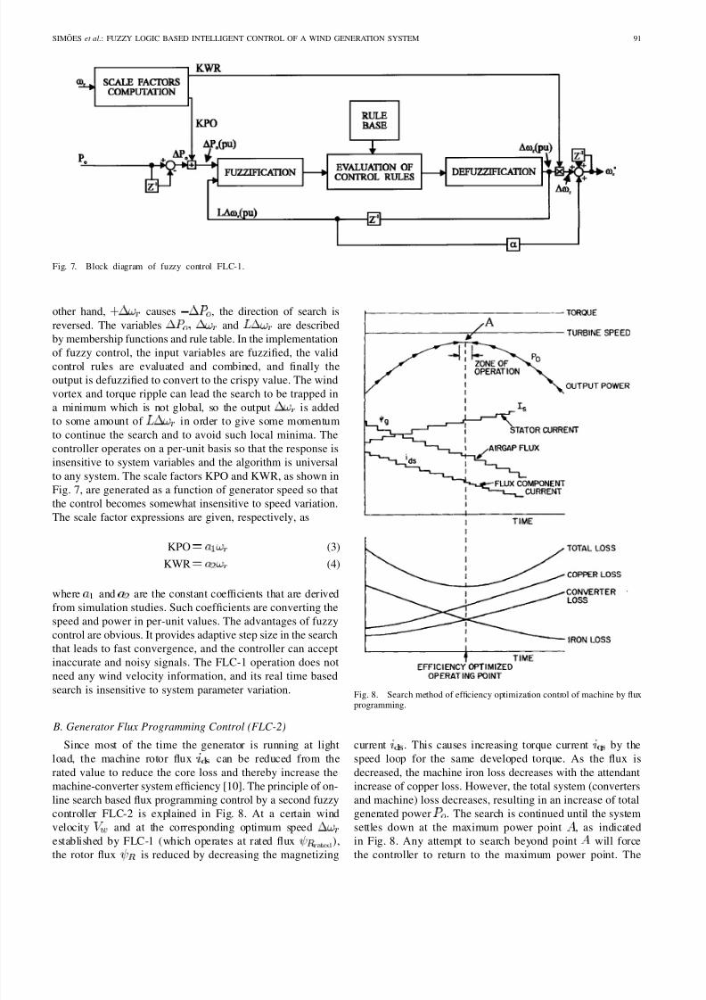
Fig. 7. Block diagram of fuzzy control FLC-1.
other hand, causes , the direction of search is
reversed. The variables and are described
by membership functions and rule table. In the implementation
of fuzzy control, the input variables are fuzzified, the validcontrol rules are evaluated and combined, and finally the
output is defuzzified to convert to the crispy value. The wind
vortex and torque ripple can lead the search to be trapped in
a minimum which is not global, so the output is added
to some amount of in order to give some momentum
to continue the search and to avoid such local minima. The
controller operates on a per-unit basis so that the response is
insensitive to system variables and the algorithm is universal
to any system. The scale factors KPO and KWR, as shown in
Fig. 7, are generated as a function of generator speed so that
the control becomes somewhat insensitive to speed variation.
The scale factor expressions are given, respectively, as
KPO (3)
KWR (4)
where and are the constant coefficients that are derived
from simulation studies. Such coefficients are converting the
speed and power in per-unit values. The advantages of fuzzy
control are obvious. It provides adaptive step size in the search
that leads to fast convergence, and the controller can accept
inaccurate and noisy signals. The FLC-1 operation does not
need any wind velocity information, and its real time based
search is insensitive to system parameter variation.
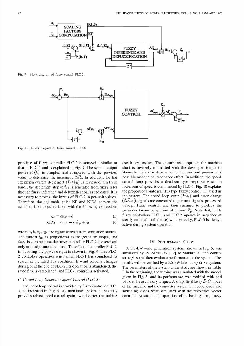
B. Generator Flux Programming Control (FLC-2)
Since most of the time the generator is running at light
load, the machine rotor flux can be reduced from the
rated value to reduce the core loss and thereby increase the
machine-converter system efficiency [10]. The principle of on-
line search based flux programming control by a second fuzzy
controller FLC-2 is explained in Fig. 8. At a certain wind
velocity and at the corresponding optimum speed
established by FLC-1 (which operates at rated flux ),
the rotor flux is reduced by decreasing the magnetizing
Fig. 8. Search method of efficiency optimization control of machine by fluxprogramming.
current . This causes increasing torque current by the
speed loop for the same developed torque. As the flux is
decreased, the machine iron loss decreases with the attendant
increase of copper loss. However, the total system (converters
and machine) loss decreases, resulting in an increase of total
generated power . The search is continued until the system
settles down at the maximum power point , as indicated
in Fig. 8. Any attempt to search beyond point will force
the controller to return to the maximum power point. The
8/3/2019 Wind Generation System
http://slidepdf.com/reader/full/wind-generation-system 6/9
92 IEEE TRANSACTIONS ON POWER ELECTRONICS, VOL. 12, NO. 1, JANUARY 1997
Fig. 9. Block diagram of fuzzy control FLC-2.
Fig. 10. Block diagram of fuzzy control FLC-3.
principle of fuzzy controller FLC-2 is somewhat similar to
that of FLC-1 and is explained in Fig. 9. The system output
power is sampled and compared with the previous
value to determine the increment . In addition, the last
excitation current decrement is reviewed. On thesebases, the decrement step of is generated from fuzzy rules
through fuzzy inference and defuzzification, as indicated. It is
necessary to process the inputs of FLC-2 in per-unit values.
Therefore, the adjustable gains KP and KIDS convert the
actual variable to variables with the following expressions
KP (5)
KIDS (6)
where and are derived from simulation studies.
The current is proportional to the generator torque, and
is zero because the fuzzy controller FLC-2 is exercisedonly at steady-state conditions. The effect of controller FLC-2
in boosting the power output is shown in Fig. 6. The FLC-
2 controller operation starts when FLC-1 has completed its
search at the rated flux condition. If wind velocity changes
during or at the end of FLC-2, its operation is abandoned, the
rated flux is established, and FLC-1 control is activated.
C. Closed-Loop Generator Speed Control (FLC-3)
The speed loop control is provided by fuzzy controller FLC-
3, as indicated in Fig. 5. As mentioned before, it basically
provides robust speed control against wind vortex and turbine
oscillatory torques. The disturbance torque on the machine
shaft is inversely modulated with the developed torque to
attenuate the modulation of output power and prevent any
possible mechanical resonance effect. In addition, the speed
control loop provides a deadbeat type response when anincrement of speed is commanded by FLC-1. Fig. 10 explains
the proportional-integral (PI) type fuzzy control [11] used in
the system. The speed loop error and error changesignals are converted to per-unit signals, processed
through fuzzy control, and then summed to produce the
generator torque component of current . Note that, while
fuzzy controllers FLC-1 and FLC-2 operate in sequence at
steady (or small turbulence) wind velocity, FLC-3 is always
active during system operation.
IV. PERFORMANCE STUDY
A 3.5-kW wind generation system, shown in Fig. 5, was
simulated by PC-SIMNON [12] to validate all the control
strategies and then evaluate performance of the system. The
results will be verified by a 3.5-kW laboratory drive system.
The parameters of the system under study are shown in Table
I. In the beginning, the turbine was simulated with the model
given in Fig. 3, and its performance was verified with and
without the oscillatory torques. A simplifie d lossy - model
of the machine and the converter system with conduction and
switching losses were simulated with the respective vector
controls. At successful operation of the basic system, fuzzy
8/3/2019 Wind Generation System
http://slidepdf.com/reader/full/wind-generation-system 7/9
SIMOES et al.: FUZZY LOGIC BASED INTELLIGENT CONTROL OF A WIND GENERATION SYSTEM 93
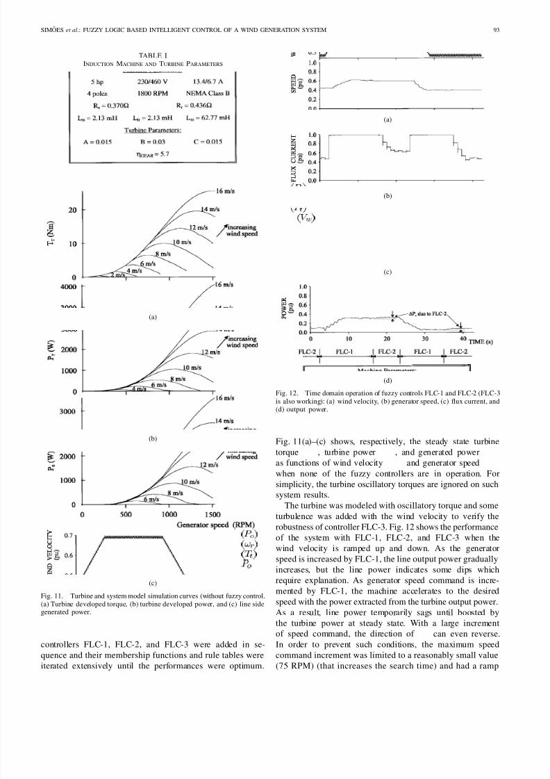
TABLE IINDUCTION MACHINE AND TURBINE PARAMETERS
(a)
(b)
(c)
Fig. 11. Turbine and system model simulation curves (without fuzzy control.(a) Turbine developed torque, (b) turbine developed power, and (c) line sidegenerated power.
controllers FLC-1, FLC-2, and FLC-3 were added in se-
quence and their membership functions and rule tables were
iterated extensively until the performances were optimum.
(a)
(b)
(c)
(d)
Fig. 12. Time domain operation of fuzzy controls FLC-1 and FLC-2 (FLC-3is also working): (a) wind velocity, (b) generator speed, (c) flux current, and
(d) output power.
Fig. 11(a)–(c) shows, respectively, the steady state turbine
torque , turbine power , and generated power
as functions of wind velocity and generator speed
when none of the fuzzy controllers are in operation. For
simplicity, the turbine oscillatory torques are ignored on suchsystem results.
The turbine was modeled with oscillatory torque and some
turbulence was added with the wind velocity to verify the
robustness of controller FLC-3. Fig. 12 shows the performance
of the system with FLC-1, FLC-2, and FLC-3 when the
wind velocity is ramped up and down. As the generatorspeed is increased by FLC-1, the line output power gradually
increases, but the line power indicates some dips which
require explanation. As generator speed command is incre-
mented by FLC-1, the machine accelerates to the desired
speed with the power extracted from the turbine output power.
As a result, line power temporarily sags until boosted by
the turbine power at steady state. With a large incrementof speed command, the direction of can even reverse.
In order to prevent such conditions, the maximum speed
command increment was limited to a reasonably small value
(75 RPM) (that increases the search time) and had a ramp
8/3/2019 Wind Generation System
http://slidepdf.com/reader/full/wind-generation-system 8/9
94 IEEE TRANSACTIONS ON POWER ELECTRONICS, VOL. 12, NO. 1, JANUARY 1997
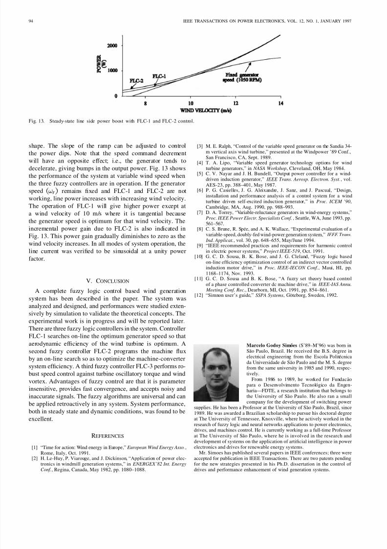
Fig. 13. Steady-state line side power boost with FLC-1 and FLC-2 control.
shape. The slope of the ramp can be adjusted to control
the power dips. Note that the speed command decrement
will have an opposite effect; i.e., the generator tends to
decelerate, giving bumps in the output power. Fig. 13 shows
the performance of the system at variable wind speed when
the three fuzzy controllers are in operation. If the generator
speed remains fixed and FLC-1 and FLC-2 are notworking, line power increases with increasing wind velocity.
The operation of FLC-1 will give higher power except at
a wind velocity of 10 m/s where it is tangential because
the generator speed is optimum for that wind velocity. The
incremental power gain due to FLC-2 is also indicated in
Fig. 13. This power gain gradually diminishes to zero as the
wind velocity increases. In all modes of system operation, the
line current was verified to be sinusoidal at a unity power
factor.
V. CONCLUSION
A complete fuzzy logic control based wind generationsystem has been described in the paper. The system was
analyzed and designed, and performances were studied exten-
sively by simulation to validate the theoretical concepts. The
experimental work is in progress and will be reported later.
There are three fuzzy logic controllers in the system. Controller
FLC-1 searches on-line the optimum generator speed so that
aerodynamic efficiency of the wind turbine is optimum. A
second fuzzy controller FLC-2 programs the machine flux
by an on-line search so as to optimize the machine-converter
system efficiency. A third fuzzy controller FLC-3 performs ro-
bust speed control against turbine oscillatory torque and wind
vortex. Advantages of fuzzy control are that it is parameter
insensitive, provides fast convergence, and accepts noisy and
inaccurate signals. The fuzzy algorithms are universal and can
be applied retroactively in any system. System performance,
both in steady state and dynamic conditions, was found to be
excellent.
REFERENCES
[1] “Time for action: Wind energy in Europe,” European Wind Energy Asso.,Rome, Italy, Oct. 1991.
[2] H. Le-Huy, P. Viarouge, and J. Dickinson, “Application of power elec-tronics in windmill generation systems,” in ENERGEX’82 Int. EnergyConf., Regina, Canada, May 1982, pp. 1080–1088.
[3] M. E. Ralph, “Control of the variable speed generator on the Sandia 34-m vertical axis wind turbine,” presented at the Windpower ’89 Conf.,San Francisco, CA, Sept. 1989.
[4] T. A. Lipo, “Variable speed generator technology options for windturbine generators,” in NASA Workshop, Cleveland, OH, May 1984.
[5] C. V. Nayar and J. H. Bundell, “Output power controller for a wind-driven induction generator,” IEEE Trans. Aerosp. Electron. Syst., vol.AES-23, pp. 388–401, May 1987.
[6] P. G. Casielles, J. G. Aleixandre, J. Sanz, and J. Pascual, “Design,installation and performance analysis of a control system for a windturbine driven self-excited induction generator,” in Proc. ICEM ’90,Cambridge, MA, Aug. 1990, pp. 988–993.
[7] D. A. Torrey, “Variable-reluctance generators in wind-energy systems,”Proc. IEEE Power Electr. Specialists Conf., Seattle, WA, June 1993, pp.561–567.
[8] C. S. Brune, R. Spee, and A. K. Wallace, “Experimental evaluation of avariable-speed, doubly-fed wind-power generation system,” IEEE Trans.
Ind. Applicat., vol. 30, pp. 648–655, May/June 1994.[9] “IEEE recommended practices and requirements for harmonic control
in electric power systems,” Project IEEE-519, Oct. 1991.[10] G. C. D. Sousa, B. K. Bose, and J. G. Cleland, “Fuzzy logic based
on-line efficiency optimization control of an indirect vector controlledinduction motor drive,” in Proc. IEEE-IECON Conf., Maui, HI, pp.1168–1174, Nov. 1993.
[11] G. C. D. Sousa and B. K. Bose, “A fuzzy set theory based controlof a phase controlled converter dc machine drive,” in IEEE-IAS Annu.
Meeting Conf. Rec., Dearborn, MI, Oct. 1991, pp. 854–861.[12] “Simnon user’s guide,” SSPA Systems, Goteborg, Sweden, 1992.
Marcelo Godoy Sim˜ oes (S’89–M’96) was born inSao Paulo, Brazil. He received the B.S. degree inelectrical engineering from the Escola Politecnicada Universidade de Sao Paulo and the M. S. degreefrom the same university in 1985 and 1990, respec-tively.
From 1986 to 1989, he worked for Fundacao
para o Desenvolvimento Tecnologico da Engen-haria—FDTE, a research institution that belongs tothe University of Sao Paulo. He also ran a smallcompany for the development of switching power
supplies. He has been a Professor at the University of Sao Paulo, Brazil, since1989. He was awarded a Brazilian scholarship to pursue his doctoral degreeat The University of Tennessee, Knoxville, where he actively worked in theresearch of fuzzy logic and neural networks applications to power electronics,drives, and machines control. He is currently working as a full-time Professorat The University of Sao Paulo, where he is involved in the research anddevelopment of systems on the application of artificial intelligence in powerelectronics and drives for renewable energy systems.
Mr. Simoes has published several papers in IEEE conferences; three wereaccepted for publication in IEEE Transactions. There are two patents pendingfor the new strategies presented in his Ph.D. dissertation in the control of drives and performance enhancement of wind generation systems.
8/3/2019 Wind Generation System
http://slidepdf.com/reader/full/wind-generation-system 9/9
SIMOES et al.: FUZZY LOGIC BASED INTELLIGENT CONTROL OF A WIND GENERATION SYSTEM 95
Bimal K. Bose (S’59–M’60–SM’78–F’89–LF’96)received the B.E. degree from Calcutta Univer-sity, India, the M.S. degree from the Universityof Wisconsin, Madison, and the Ph.D. degree fromCalcutta University in 1956, 1960, and 1966, re-spectively.
For the last nine years, he has been the CondraChair of Excellence in Power Electronics at theUniversity of Tennessee, Knoxville. Prior to that, heworked for 11 years at General Electric Corporate
Research and Development, Schenectady, NY, andfor five years at the Ransselaer Polytechnic Institute, Troy, NY. He didextensive research in power electronics and drives that includes soft-switchedconverters, microcomputer control, simulation, EV drives and application of an expert system, fuzzy logic, and a neural network in power electronicsystems. He has published more than 130 papers and authored and editedfive books in the power electronics and drives areas. He also holds 18 U.S.patents.
Dr. Bose received the IEEE Industry Application Society OutstandingAchievement Award (1993) for "outstanding contributions in the applicationof electricity to industry," the IEEE Industrial Electronics Society EugeneMittelmann Award (1994) in "recognition of outstanding contributions toresearch and development in the field of power electronics and a lifetimeachievement in the area of motor drives," the IEEE Region 3 OutstandingEngineer Award (1994) for "outstanding achievements in power electronicsand drives technology," and the IEEE Lamme Gold Medal (1996) for"contributions to the advancement of power electronics and electrical machine
drives."
Ronald J. Spiegel (M’73) received the Ph.D. degreein electrical engineering, with a minor in opticalphysics, from the University of Arizona, Tucson, in1970.
His area of expertise is electromagnetics, andhis Ph.D. dissertation dealt with the detection of atmospheric pollutants using laser radar (lidar) tech-niques. Subsequent to graduation, he was a PostDoctoral Fellow in biomedical engineering at DukeUniversity, Durham, NC, from 1971 to 1972, where
he conducted research in the interaction of electro-magnetic fields with biological media. After completing his Fellowship, heheld positions in private industry such as the Boeing Aerospace Company andat research institutes such as the IIT Research Institute and Southwest ResearchInstitute where he worked in the Department of Defense on military-relatedresearch. This research included electromagnetic compatibility (EMC), nuclearelectromagnetic pulse (EMP), radar cross-section analysis, and antennas. In1980, he joined the U.S. Environmental Protection Agency (EPA) as Chief of the Bioengineering Branch where he supervised a multidisciplinary team of researchers with the mission of conducting research in the area of electromag-netic field interaction with biological objects relating to experimental methods,dosimetric methods, model development, and mitigation approaches. AfterCongress terminated funding for the EPA’s program on the biological effectsof electromagnetic radiation, he relocated to the Air Pollution Preventionand Control Division and is currently researching cutting-edge environmentaltechnology development. This area includes fuel cell application to landfillmethane gas, intelligent control (fuzzy logic, neural networks, and genetic
algorithms) of electric motors and wind turbines, and solar photovoltaics.Dr. Spiegel is a Member of Sigma Xi and is a Registered Professional En-
gineer. He was awarded the EPA’s Scientific and Technological AchievementAward for 1984 and 1990 and was a Finalist in the 1996 Discover Awardsfor Technological Innovation.