Embed Size (px)
Citation preview
Abstract—This paper proposes the wind generator system using the matrix converter method and evaluates them to select as a commutation method of the matrix converter. A matrix converter is the power converter which can output arbitrary voltage and frequency from AC input. The commutation of matrix converters must be careful so that the short circuit of power supply and the open circuit of load do not occur. The commutation methods are classified roughly into the voltage commutation method and the current commutation method. The fundamental performance of the wind power generation system using matrix converters are verified by discussing the simulation and experimental results.
Index Terms—Wind power generation system, matrix
converter
I. INTRODUCTION
matrix converter is the AC to AC converter which can output arbitrary voltage and frequency. It is high efficiency and small comparing with conventional
power converters. The wind generator system using matrix converter as a converter was proposed. For a realization of the matrix converter method, the whole system including the windmill model, power system, main circuit consists of nine bidirectional switches and controllers are simulated. And the possibility of a realization using the real machine is discussed.
In this paper, the matrix converter method is realized with simulation system using the wind emulator [5]. Also the wind generator system using the PWM converter is tested with experimental system to compare with the matrix converter method. In the simulation results, it is shown that the matrix converter has the sufficient performance as variable-speed wind generator system.
II. WIND POWER GENERATION SYSTEM
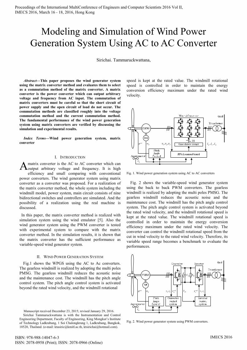
Fig.1 shows the WPGS using the AC to Ac converters. The gearless windmill is realized by adopting the multi poles PMSG. The gearless windmill reduces the acoustic noise and the maintenance cost. The windmill has the pitch angle control system. The pitch angle control system is activated beyond the rated wind velocity, and the windmill rotational
Manuscript received December 23, 2015; revised January 29, 2016. Sirichai Tammaruckwattana is with the Instrumentation and Control
Engineering Department, Faculty of Engineering, King Mongkut’s Institute of Technology Ladkrabang, 1 Soi Chalongkrung 1, Ladkrabang, Bangkok, 10520, Thailand. (e-mail: [email protected], [email protected]).
speed is kept at the rated value. The windmill rotational speed is controlled in order to maintain the energy conversion efficiency maximum under the rated wind velocity.
321 ,, vvvwvu iii ,,g
0V
set18
Fig. 1. Wind power generation system using AC to AC converters
Fig. 2 shows the variable-speed wind generator system
using the back to back PWM converters. The gearless windmill is realized by adopting the multi poles PMSG. The gearless windmill reduces the acoustic noise and the maintenance cost. The windmill has the pitch angle control system. The pitch angle control system is activated beyond the rated wind velocity, and the windmill rotational speed is kept at the rated value. The windmill rotational speed is controlled in order to maintain the energy conversion efficiency maximum under the rated wind velocity. The converter can control the windmill rotational speed from the cut in wind velocity to the rated wind velocity. Therefore, its variable speed range becomes a benchmark to evaluate the performances.
aa iv , refaV
dcC dcR
dcV refsV ss iv ,g
0V
set
Fig. 2. Wind power generator system using PWM converters.
Modeling and Simulation of Wind Power Generation System Using AC to AC Converter
Sirichai. Tammaruckwattana,
A
Proceedings of the International MultiConference of Engineers and Computer Scientists 2016 Vol II, IMECS 2016, March 16 - 18, 2016, Hong Kong
ISBN: 978-988-14047-6-3 ISSN: 2078-0958 (Print); ISSN: 2078-0966 (Online)
IMECS 2016

III. CONTROL SYSTEM
A. Wind Turbine Emulator [2]
Fig. 3 show the basic structure of wind turbine emulator.
The wind turbine model is based on the blade element
momentum theory [1]. The wind turbine model consists of
the three dimensional table data of wind turbine
characteristics and the mechanical model considering the
difference between real wind turbine and induction motor.
The wind velocity V0 is given as a condition of emulation.
The windmill rotational speed ωr is detected with the rotary
encoder (RE). The V0 and ωr are used as inputs of the three
dimensional table.
Fig. 3. Wind turbine emulator.
B. Commutation Method of Matrix Converter
Fig 4 shows the main circuit of MC. A matrix converter needs the 6 RB-IGBTs for each phase shown in fig. 4. The commutations of matrix converter must be careful so that the short circuit of input side and open circuit of output side do not happen. The voltage commutation and current commutation methods are proposed [3]. The voltage commutation method decides the commutation patterns based on relations of the magnitude of input voltages V1, V2, and V3. The current commutation decides the commutation patterns depending on the directions of output current I.
V1
V2
S1a
S1b
S2a
S2b
Vo
Io
V3
S3a
S3b
S1u
S1v
S1w
S2u
S2v
S2w
S3u
S3v
S3w
Vu
Vv
Vw
V1
V2
V3
InputVi
OutputVo
Fig. 4. Main circuit using RB-IGBT of matrix converter.
C. Converter Control Method of PWM Converter [4]
Fig. 5 shows the converter control method. In the operating range under the rated wind velocity, the speed regulator is used jointly with the torque current feed-forward control. In the operating range over the rated wind velocity, the pitch angle control system controls the wind turbine torque, and the converter control system carries out the electric power control and torque current feed-forward control.
Fig.5. Converter control system of PWM converter.
D. Inverter Control Method of PWM Converter [4]
Fig. 6 shows the inverter control method. The wind speed control and electric power control are all carried out in the converter side. The inverter control system regulates the DC link voltage at 35V in order to carry out the wind speed control and electric power control in the converter side, and also in order to carry out the system cooperation.
sL
sL
s
refsdV
refsqV
se3
32
dcV
constdcV
refsqi
sdi
sqi
PI
PI
PI
Fig.6. Inverter control system of PWM converter.
IV. IMPLEMENTATION PROCESS
The implementation of matrix converter is evaluated with the simulation study using Matlab/Simulink. The Simulink models for matrix converter method are implemented. The Simulink models consider the windmill, the main circuits using RB-IGBT, the control systems, and the pitch angel control system. This paper verifies the fundamental
grefimT
V2003
Proceedings of the International MultiConference of Engineers and Computer Scientists 2016 Vol II, IMECS 2016, March 16 - 18, 2016, Hong Kong
ISBN: 978-988-14047-6-3 ISSN: 2078-0958 (Print); ISSN: 2078-0966 (Online)
IMECS 2016

implementation of matrix converter by comparing with the implementation of PWM converter with simulation.
Fig.7 shows the change of the wind velocity V0 [m/s]. The change of wind velocity includes the ranges of low wind velocity, middle wind velocity, and high wind velocity. The high wind velocity means the wind velocity that exceeds the rated value. All ranges include the sinusoidal change of amplitude 0.5 [m/s] and 0.2 [Hz].
Fig.7. Wind velocity.
Figs. 8 and 9 show the simulation results of matrix
converter method and the experimental results of PWM converter method. The simulation models for the wind power generation system using matrix converter are implemented by using MATLAB/Simulink. The simulation models consider the wind velocity, the main circuits, the control system. The signal fluctuations are superimposed at each wind velocity. The all schemes were simulated for the same change of wind velocity.
V. CONCLUSIONS
This paper described the control strategy of variable-speed wind power generation system using matrix converters. The steady state and transient responses for wind velocity changes were tested for the variable-speed wind power generation system using PWM converter with the real machine. The simulation models of the variable-speed wind power generation system using matrix converter are implemented by using MATLAB/Simulink. The simulation results are compared with the experimental results of the variable-speed wind power generation system using PWM converter.
(a). Generated power
(b). Wind turbine Torque
(c). Tip speed ratio
(d). Rotational speed Reference
Proceedings of the International MultiConference of Engineers and Computer Scientists 2016 Vol II, IMECS 2016, March 16 - 18, 2016, Hong Kong
ISBN: 978-988-14047-6-3 ISSN: 2078-0958 (Print); ISSN: 2078-0966 (Online)
IMECS 2016

(e). Rotational speed
(f). Power reference
(g). Pitch angle
(h). Pitch signal
Fig.8 Simulation results for matrix converter.
(a). Generated power
(b). Wind turbine Torque
(c). Tip speed ratio
(d). Rotational speed Reference
Proceedings of the International MultiConference of Engineers and Computer Scientists 2016 Vol II, IMECS 2016, March 16 - 18, 2016, Hong Kong
ISBN: 978-988-14047-6-3 ISSN: 2078-0958 (Print); ISSN: 2078-0966 (Online)
IMECS 2016

(e). Rotational speed
(f). Power reference
(g). Pitch angle
(h). Pitch signal
Fig.9 Experimental results for PWM converter.
REFERENCES
[1] Anderson, P. M.; Bose, A.: Stability Simulation of Wind Turbine System., IEEE Transactions on Power Apparatus and Systems, Vol. PAS-102, No. 12, December 1983, pp.3791 – 3795
[2] K. Ohyama, T. Nakashima: “Wind Turbine Emulator Using Wind Turbine Model Based on Blade Element Momentum Theory”, International Symposium on Power Electronics, Electrical Drives, Automation and Motion T. SPEEDAM pp.762 - 765 (2010)
[3] Investigating R&D Committee on Improvement of Practical and Applied Technology of Direct AC to AC Conversion Circuit: Trend and Applications of Matrix Converters, IEEJ, No.1111, pp.17-18 (2008)
[4] S. Tammaruckwattana, K. Ohyama: “Experimental Verification of Variable Speed Wind Power Generation System Using Permanent Magnet Synchronous Generator by Wind Turbine Emulator”, International Conference IECON (2012) (in Canada)
[5] Tammaruckwattana, S., Ohyama, K. and Arinaga, S. (2015), Wind turbine emulator based on blade element momentum theory for variable-speed wind power generation system. IEEJ Trans Elec Electron Eng, 10: S96–S107. doi: 10.1002/tee.22170
Proceedings of the International MultiConference of Engineers and Computer Scientists 2016 Vol II, IMECS 2016, March 16 - 18, 2016, Hong Kong
ISBN: 978-988-14047-6-3 ISSN: 2078-0958 (Print); ISSN: 2078-0966 (Online)
IMECS 2016