Embed Size (px)
Citation preview
Oracle8i™ and Oracle® Fail Safe on
Microsoft® Windows®
2000Solution Guide
Enterprise Systems Group (ESG) Storage Systems Group (SSG)
Dell White PaperBy Solution Enablement Lab & Showcase
May 2001

May 2001
ContentsExecutive Summary..................................................5Introduction.............................................................6About Oracle8i, Oracle Fail Safe and Clustering.....8
Microsoft Cluster Services...................................8Oracle Fail Safe Clustering..................................8
Planning the System Configuration.......................10Planning Steps...................................................10Choosing the Platform.......................................10
Dell PowerVault SCSI vs. Fibre Channel Storage Subsystem....................................................................11Fibre Channel Characteristics......................................11SCSI Storage Characteristics.......................................11
Sizing the system...............................................12Planning the Storage subsystem.......................13
PERC 2/DC Controller Disk Array Limitation...............13Planning the Network........................................14Limitations.........................................................15
Pre-Installation Set-up...........................................16Equipment Needed............................................16
MSCS Clustering and Installation Overview.........17Overview of Installation Steps 1-9 (Hardware): 17Overview of Installation Steps 10-20 (Software):...........................................................................18
Installation of Oracle Fail Safe.............................20Outline of configuration steps...........................20Oracle8i and Oracle Fail Safe Installation........21Oracle8i Configuration and Installation Steps. .21
Oracle Fail Safe (OFS) Configuration and Installation.............................................................22
Overview.............................................................22OFS Pre-Installation Steps................................23OFS Installation Steps.......................................23
Welcome Screen...........................................................23File Locations...............................................................23Installation Types.........................................................24Available Product Components.....................................25Reboot Needed.............................................................25Summary Screen..........................................................25Installation....................................................................25Configuration Tools......................................................25Oracle Fail Safe Account/Password..............................25End of Installation........................................................26
Post-installation Steps.......................................26Oracle Fail Safe Manager..................................28
Revision Date: 5/12/2023 Page 3 of 52 Dell ESG/SSG Worldwide Marketing

Start the Oracle Fail Safe Manager..............................29Verify Cluster...............................................................30Add a new Group..........................................................31Failback Policies...........................................................32Finish Creating the Group............................................32Add the IP address resource to the group....................33Finish Adding the Virtual Address................................33Add the Oracle8i database to the group.......................34
Select the database............................................35Database Authentication..............................................36Adding the database.....................................................37The Clustered Database...............................................38Verify the cluster..........................................................38Verify the group............................................................39
Administration and maintenance...........................40Cluster operation and administration...............40
Moving the Oracle services to another node (planned failover)........................................................................43Shutting down the cluster............................................44
Oracle8i operation and administration.............45Configuring Net8...............................................45
Post-Installation Testing........................................46Conclusion..............................................................47
Best Practices and Key Findings.......................47Conclusion.........................................................48Contacts.............................................................48
Appendix A: Vendor Information...........................49Oracle Corporation............................................49Dell Computer Corporation...............................49Intel Corporation...............................................49Microsoft Corporation.......................................49
Appendix B: Reference Documents.......................50Appendix C: Glossary ....................................................51
Table of TablesTable 1: Characteristics of Various RAID Levels......................................................12Table 2: Oracle8i System Requirements for Storage Volumes.................................13Table 3: Sample IP Addresses for Cluster Nodes and for WINS, DNS, and Gateway
Servers................................................................................................................14Table 4: Recommended Installation Procedures......................................................20
Table of FiguresFigure 1: Example of network cabling connections.................................................14Figure 2: Location of software and database components……………………..………..
……………22Figure 3: OFS screen for entering file locations......................................................24Figure 4: Oracle Fail Safe Account/Password..........................................................26Figure 6: Connect to Cluster....................................................................................29Figure 7: Oracle Fail Safe Manager.........................................................................30Figure 8: Create group - Step 1: General.................................................................31Figure 9: Create group - Step 2: Failback policies...................................................32Figure 10: Add resource to Group - Virtual address screen.....................................33Figure 11: Add resource to group............................................................................34
Revision Date: 5/12/2023 Page 4 of 52 Dell ESG/SSG Worldwide Marketing

Figure 12: Database identity....................................................................................35Figure 13: Database authentication.........................................................................36Figure 14: Adding the database...............................................................................37Figure 15: The clustered database...........................................................................38Figure 16: Oracle Fail Safe Manager.......................................................................41Figure 17: The Oracle8i Database Group.................................................................42Figure 18: Group selection menu.............................................................................43Figure 19: Confirm move group dialog box..............................................................44Figure 20: Moving group screen..............................................................................44
Revision Date: 5/12/2023 Page 5 of 52 Dell ESG/SSG Worldwide Marketing

Section 1Executive Summary
This paper explains the installation and configuration procedures necessary to build an Oracle® Fail Safe (OFS) high-availability cluster system using Microsoft® Cluster Services (MSCS) on Dell hardware. Oracle Fail Safe clustering is designed to provide high server availability for Oracle8i™ databases. The goal of this paper is to serve as a guide for Dell field technicians and sales persons on the steps necessary to design and configure a two-node Oracle Fail Safe failover cluster system.
The Solution Engineering team at Dell Computer Corporation’s world headquarters in Round Rock, Texas, USA has extensively tested the solutions described in this guide. Dell’s Solution Engineering teams are dedicated to testing complete application solutions on proven Dell server and storage configurations. Wherever possible, this paper points out lessons learned, tips and tricks, best practices, etc. Dell’s goal is to help customers save time and eliminate some of the frustrations of learning through trial and error. This should allow customers to deploy critical business solutions more quickly and easily on proven, reliable systems.
This paper provides the steps necessary to plan, configure, install and test an Oracle Fail Safe cluster on Dell hardware. Included in this paper are following steps:
Planning the system
Elementary sizing
Configuring the hardware
Installing Microsoft Windows® 2000
Installing Microsoft Cluster Services (MSCS)
Installing Oracle8i, version 8.1.7
Installing Oracle Fail Safe 3.1.1
Clustering an Oracle8i database
Revision Date: 5/12/2023 Page 6 of 52 Dell ESG/SSG Worldwide Marketing

Section 2Introduction
Oracle Fail Safe clustering is designed to provide high server availability for Oracle8i databases. It does not provide non-stop operation, but provides sufficient availability for most mission-critical applications. The goal of this paper is to serve as a guide for Dell field technicians and sales persons on the steps necessary to design and configure a two-node Oracle Fail Safe failover cluster system. The solution proposed in this paper involves the configuration of two Dell™ PowerEdge™ servers (of the same type) that are clustered using Microsoft Cluster Services, and that run Oracle Fail Safe for failover clustering.
The solution can be configured using either of the following known, certified Dell PowerEdge Cluster Solutions:
SE100, SE200, or SL200 (SCSI solutions)Platform Guides for these solutions are at the following URL:http://support.dell.com/us/en/docs/index.asp?cc=12&ct=89
FE100 or FL100 (Fiber channel solutions)Platform Guides for these solutions are at the following URL:http://support.dell.com/us/en/docs/index.asp?cc=12&ct=89
The following software will be installed:
Microsoft Windows 2000 Advanced Server
Service Pack 1 for Windows 2000 (should be included in the Windows 2000 installation)
Microsoft Cluster Services (MSCS)
Oracle8i, version 8.1.7 Enterprise Edition
Oracle Fail Safe 3.1.1
This paper will explain what MSCS and Oracle Fail Safe clustering are and why failover is used. It will also cover system planning and system setup from the ground up - from hardware setup and configuration to software installation.
Note about software versions: This paper describes and used Oracle8i, version 8.1.7 and Oracle Fail Safe version 3.1.1. This solution guide can also be applied to the currently shipping Oracle Fail Safe version 3.1.2
Revision Date: 5/12/2023 Page 7 of 52 Dell ESG/SSG Worldwide Marketing

Section 3About Oracle8i, Oracle Fail Safe and Clustering
Microsoft Cluster Services
Microsoft Cluster Services (MSCS) is a service that may be installed with Windows 2000 Advanced Server or Datacenter Server. Its purpose is to provide high server availability through failover clustering when cluster-aware applications are run. Cluster-aware means that the application provides functionality that allows it to take advantage of the failover features provided by MSCS. In this paper, the cluster-aware application is Oracle8i, version 8.1.7 using Oracle Fail Safe (OFS). Other types of cluster-aware applications may include knowledge management software, ERP, and file and print services.
Oracle Fail Safe Clustering
Oracle Fail Safe clustering provides high server availability such that if one system fails or is purposely taken offline, Oracle8i processing switches to a second, clustered system. This switch is known as a failover. Failover is designed to minimize system downtime. Once a failover occurs, the failed system may be restored, brought back online, and it is possible to resume processing by switching back to the restored system – this is called failback.
Each system that is part of a cluster is called a node. Windows 2000 Advanced Server allows for up to two nodes in a cluster, and Window 2000 Datacenter Server allows for up to four nodes in a cluster. The nodes in a cluster share a common set of cluster resources, such as disk drives. Each node is connected to a network and can communicate with all other nodes. The nodes send each other network messages called heartbeat messages. If the MSCS software detects the loss of a heartbeat from one of the nodes in the cluster, then failover will occur for that node.
Note: Windows 2000 Advanced Server supports up to two nodes in a failover cluster, while Windows 2000 Datacenter Server supports up to four nodes in a failover cluster.
When a failover occurs, the user connections to the failed node will be lost, so users must log in again when the second clustered node takes over. It takes a very short period of time for this failover process to occur, during which time the users will be waiting. So failover does not provide 100% uptime, but close to it. The main use for failover is to provide high server availability in cases such as the following:
Revision Date: 5/12/2023 Page 8 of 52 Dell ESG/SSG Worldwide Marketing

1. System failure – this includes Oracle8i failures and hardware failures that cause the system to hang or shutdown.
2. Planned system downtime – for things as upgrades, system maintenance, etc. It is possible to manually take the first clustered node offline, causing failover to the second node. The second node will continue processing user requests, while the first node can be upgraded without causing downtime for the users.
MSCS allows two main methods for failover clustering – active/active and active/passive. (A one-node cluster is also an option, but is not discussed here.)
Active/Active Clustering All servers run their own workload simultaneously. Every computer in the cluster is available to do real work (is active), and each computer in the cluster is also available to recover the resources and workload of any other computer in the cluster. There is no need to have a secondary, idle server waiting for a failure. One drawback with active/active clustering is the risk of overloading the node that takes over for the failed node because it must now perform its own work plus that of the failed node.
Active/Passive Clustering One node in the cluster remains idle, while the other node (or nodes if running Datacenter Server) is active. If the active node fails, processing of cluster-aware applications (e.g., Oracle8i) will be switched to the passive node. Once the failed node is restored, the application can revert back to the original node, so that it becomes the active node again. This leaves the passive node available for the next time failover is needed. The primary drawback with active/passive clustering is the cost associated with having a secondary system sitting idle. Upfront planning and analysis will assist in determining which method of clustering is acceptable and viable.
Note: This paper will focus on active/passive Oracle Fail Safe clustering on a two-node cluster running Windows 2000 Advanced Server and MSCS.
Revision Date: 5/12/2023 Page 9 of 52 Dell ESG/SSG Worldwide Marketing

Section 4Planning the System Configuration
Before the installation process begins, it is important to thoroughly plan the configuration as this can help to avoid costly reconfiguration time. It is necessary to both size and plan the system from the beginning. It can be very difficult to add additional resources to an existing cluster at a later time.
Planning Steps
Planning an Oracle Fail Safe cluster involves the following steps:
Choosing the hardware platform
Sizing the system
Designing the storage subsystem
Designing the network
Sizing the system is not the focus of this paper, however a few sizing tips are provided. The storage subsystem is critical since the shared disk is one of the key components of the failover cluster. Another key component is the use of a number of TCP/IP network addresses. Planning these components ahead of time is key to a successful cluster installation.
Choosing the Platform
The first determination is which PowerEdge Cluster solution (particularly the PowerEdge server platform) is appropriate for the customer. The choice must come from the list of Dell certified configurations. To find the certified solutions, see the Dell document entitled:
“Dell PowerEdge Cluster SE100, SE200, and SL200 Platform Guide” for SCSI systems or “Dell PowerEdge Cluster FE100/FL100 Platform Guide” for Fibre Channel systems.
These documents can be downloaded from the Dell web site at http://support.dell.com/us/en/docs/index.asp?cc=12&ct=89. They give the specifics on the minimum hardware requirements needed to build a cluster for each solution. This same site also has information on how to configure storage subsystem, and on how to install MSCS. The installation and configuration of Oracle Fail Safe is covered in this paper, including specific considerations to take into account in regard to implementing Oracle Fail Safe on a MSCS.
Revision Date: 5/12/2023 Page 10 of 52 Dell ESG/SSG Worldwide Marketing

Dell PowerVault SCSI vs. Fibre Channel Storage Subsystem
Whether the customer needs a SCSI solution or a fibre channel solution will depend on their needs and preferences. Here are some characteristics of each type of solution that will help determine which is best:
Fibre Channel Characteristics
Fibre Channel provides high availability through redundant Fibre Channel host bus adapters (HBAs) in the PowerEdge server and dual storage processors in the PowerVault storage system.
Fibre Channel also requires dual standby power supplies (SPS) in the PowerVault storage system, which provides integrity of the storage processor write-cache in case one power supply fails. Thus write-caching may be enabled, which will improve disk write performance. With SCSI, it’s not possible to use write-caching with a failover cluster.
Fibre Channel allows for easy storage subsystem growth. It is relatively easy to add disks to the PowerVault 650F storage system without having to shutdown the system. A direct connect Fibre Channel solution supports up to 120 disks on one PowerVault 650F. (Dell is in the process of evaluating the PowerVault 660F for use in OFS and MSCS clusters). For a SAN solution, it is possible to have up to 480 disks on one cluster that connect through a fibre channel switch. The same switch can also support additional stand-alone systems and clusters.
Although Fibre Channel systems are more expensive than SCSI, the expandability and flexibility is much greater than SCSI.
SCSI Storage Characteristics
The SCSI solutions (SE100, SE200, and SL200) allow at most two (2) PERC 2/DC RAID controllers for the clustered disks. Therefore a maximum of 24 disk drives for the SE100, and a maximum of 48 disk drives for the SE200 and SL200 can be configured for the cluster’s shared disks. If that amount is not sufficient for the customer’s current and future growth needs, then consider Fibre Channel.
Fibre Channel systems are more expensive, so if the customer only needs a small number of disks and does not require the high availability provided only by fibre channel, then SCSI solutions may be appropriate and will be less expensive. Again, consider the expected growth by the customer.
Revision Date: 5/12/2023 Page 11 of 52 Dell ESG/SSG Worldwide Marketing

Sizing the system
With either a SCSI solution or a Fibre Channel solution it is important that to properly size the system before beginning the configuration and installation. It is very difficult to add additional storage to a cluster system once MSCS and Oracle Fail Safe have been installed and configured. This is because clustered storage cannot be easily modified while the cluster is up and running. With the SCSI solution, there are several steps that require both nodes in the cluster to be shutdown or rebooted, so adding storage requires significant downtime in a system that is designed for maximum uptime.
When sizing the system, it is important in mind not only the storage capacity needed, but also the performance levels that must be maintained. A single disk drive can handle approximately 85 I/Os per second before latencies increase and performance begins to degrade. If the choice is a SCSI disk subsystem and it is configured with a shared volume(s) as RAID 5, it will lead to a significant number of extra I/Os during writes as well as increased write latencies due to the RAID 5 parity. Table 1 provides a review of RAID and describes the additional I/Os incurred by RAID.
Table 1: Characteristics of Various RAID Levels
RAID LevelFault Tolerance
Logical Reads
Physical Reads
Logical Writes
Physical I/Os
RAID 0 None 1 1 1 1RAID 1 or 10 Best 1 1 1 2RAID 5 Moderate 1 1 1 4 (2
reads, 2 writes)
Note: Because of this additional overhead incurred by RAID 5 writes, Dell never recommends that RAID 5 be used in an Oracle8i database configuration. This is especially true of the volume(s) containing the redo log files. It is acceptable to use RAID 5 on volume(s) used exclusively for archive log files.
The storage subsystem should be sized accordingly in order to keep the number of physical I/Os within acceptable limits. A storage subsystem that exceeds the physical limitations of the disk drives will experience high latencies that will in turn severely affect system performance.
Planning the Storage subsystem
In addition to carefully sizing the storage subsystem, the storage subsystem must be planned with the cluster functionality in mind. Creating both volumes for the cluster as well as volumes for a well-designed Oracle8i system requires that several shared volumes be created. Table 2 describes some of the guidelines.
Revision Date: 5/12/2023 Page 12 of 52 Dell ESG/SSG Worldwide Marketing

Table 2: Oracle8i System Requirements for Storage VolumesVolume Description Fault
Tolerance
Quorum Drive This is used for the cluster quorum and should not be used for any other purposes.
RAID 1
Oracle8i Redo Log files
The redo log files should be on their own mirrored volume for both performance and database protection.
RAID 1
Database schema object data files
The database files themselves should be placed on a RAID 10. The number of drives will vary depending on performance requirements.
RAID 10
Archive log files It is a good idea to either keep the archive log files on a separate shared volume or on a network drive that is mapped to the same drive letter on each cluster node.
RAID 1 or RAID 10
It is important to plan this in advance in order to avoid costly reconfiguration time later.
PERC 2/DC Controller Disk Array Limitation
PERC 2/SC and PERC 2/DC are Dell-customized AMI controllers, and there are some limitations with the RAID configuration utility. There is a maximum of eight (8) disk arrays that can be configured per controller (not per channel!). When using RAID 10, each set of two disks must be first configured as its own disk array of RAID 1. Then it is possible to span these arrays to create RAID 10. Herein lies the problem. To create a RAID 10 array out of a total of 20 disks (ten (10) disks mirrored and striped with ten (10) other disks) it would be necessary to create ten (10) RAID 1 disk arrays and span them – but this can’t be done. There is a maximum of eight (8) disk arrays. This leaves four (4) disks that cannot be configured! Since no one would want to leave disks unconfigured, time spent in planning and sizing the system so that sufficient disk space is installed will save time and aggravation later.
Note: In addition, it is very important that the PERC 2/DC controllers in both nodes be running version 2.62 of the PERC 2/DC device driver. They must also be running version 1.01 of the PERC 2/DC firmware.
Planning the Network
At least two network cards are required in each of the cluster nodes – that’s four NICs for the two-node cluster. One NIC is for the public LAN and one for the private, node-to-node cluster interconnect. The public network is for communication with clients and domain controllers. The private network is for node-to-node communication, cluster status signals, and cluster management. Having two cards provides fault tolerance (redundancy) for cluster communications in
Revision Date: 5/12/2023 Page 13 of 52 Dell ESG/SSG Worldwide Marketing

case of a failure on one of the networks. The private network can be a crossover cable. See Figure 1 below for a diagram of the network.
Figure 1: Example of network cabling connections
It is necessary to provide static IP addresses for each of the four NICs, plus one more IP address for the Cluster Service (discussed later). That is a total of 5 static IP addresses needed for the two-node cluster. The public NIC must be on a different subnet from the private NIC. Table 3 shows an example of IP addresses for the cluster nodes and for WINS, DNS, and Gateway servers.
Note: With the exception of the private network IP addresses (10.10.10.1 and 10.10.10.2), the IP addresses given below are for example only and may not be used in another network! Actual IP addresses will depend on individual networks.
Table 3: Sample IP Addresses for Cluster Nodes and for WINS, DNS, and Gateway Servers
Usage Cluster Node A Cluster Node BPublic Network (to clients) 192.168.1.101
(your subnet.x.x)192.168.1.102
(your subnet.x.x)Public Network Subnet Mask 255.255.255.0Private Network (node-to-node interconnect)
10.10.10.1(you may use this
value)
10.10.10.2(you may use this
value)Private Network Subnet Mask 255.255.255.0Cluster Service 192.168.1.2
(your subnet.x.x)WINS Servers Primary WINS 192.168.1.11 (your
subnet.x.x)Secondary WINS 192.168.1.12 (your
subnet.x.x)DNS Servers Primary DNS 192.168.1.21 (your subnet.x.x)
Secondary DNS 192.168.1.22 (your subnet.x.x)
Default Gateway 192.168.1.1 (your subnet.x.x)
Revision Date: 5/12/2023 Page 14 of 52 Dell ESG/SSG Worldwide Marketing

Limitations
Oracle Fail Safe and Microsoft Cluster Services provide for a quick resumption of service in the event of a system hardware or software failure. However, MSCS does not provide for continuous uptime. In the event of a failure, the node (and Oracle8i) is essentially shutdown and the database is started on the standby node. All users are disconnected and must reconnect. This constitutes loss of services. Oracle Fail Safe and MSCS only provide a quick way to get running again. In addition, since the same data files are used on both nodes, Oracle Fail Safe and MSCS will not survive the loss of data either due to an I/O failure or data corruption due to software or user error.
Revision Date: 5/12/2023 Page 15 of 52 Dell ESG/SSG Worldwide Marketing

Section 5Pre-Installation Set-up
Pre-installation set-up is comprised of setting up the hardware and configuring the shared storage subsystem. Once the hardware is set-up and configured properly the next step is the software installation process.
Equipment Needed
The following is a generic listing of the types of equipment needed to perform an Oracle Fail Safe installation in a clustered environment:
Two (2) Dell PowerEdge servers
PowerVault Shared storage subsystem
Two (2) network cards per server
Application Software
Revision Date: 5/12/2023 Page 16 of 52 Dell ESG/SSG Worldwide Marketing

Section 6 MSCS Clustering and Installation Overview
The following information is a summarized checklist of what needs to be done - from beginning to end – to set up a clustered Dell server and storage environment, install Oracle Fail Safe and verify correct set-up and installation. Steps 1-9 below deal specifically with setting up the hardware, while steps 10-20 deal with the operating system and application software.
Details about how to perform steps 2 through 9 are explained in detail in the Installation and Troubleshooting Guide for the chosen platform. Either:
Dell™ PowerEdge™ Cluster FE100/FL100 Installation and Troubleshooting Guide or Dell™ PowerEdge™ Cluster SE100, SE200, and SL200 Systems Installation and Troubleshooting Guide
When completing steps 2-9 below, follow chapters 2, 3, 4, and 5 of the appropriate Installation and Troubleshooting Guide to configure hardware and enable it specifically for clustering. These Installation and Troubleshooting Guides can be downloaded from the same URL as the Platform Guides: http://support.dell.com/us/en/docs/index.asp?cc=12&ct=89. There are additional notes listed below that were not included in those chapters that are important for a successful implementation.
Beginning with Step 10 (installation of Windows 2000 Advanced Server), the steps below describe the installation, configuration and testing of the operating system and Oracle8i applications in a clustered environment. For steps 10 and beyond, continue with this document for detailed information.
Overview of Installation Steps 1-9 (Hardware):
1. Once the platform is chosen, follow the information about the hardware and disk configuration in this paper to ensure that all the necessary hardware is on hand.
2. If the PowerVault 2xxS does not have two (2) ESEMs or two (2) SEMMs, add the additional ESEM/SEMM now.
3. Verify that the ESEMs or SEMMs in the PowerVault 2xxS are set to forced join mode.
4. Cable the system hardware for clustering.
Revision Date: 5/12/2023 Page 17 of 52 Dell ESG/SSG Worldwide Marketing

Note: Start up the systems and perform step 5 on one node at a time.
5. Enable cluster mode in the BIOS configuration utility for each controller(s) attached to a shared storage system. (First on Node A then on Node B).
Note: To perform step 5, press <Ctrl+M> during boot to enter the BIOS configuration utility, then select Objects→Adapter→Adapter 0 or 1 (the one that has shared storage). Then highlight “Cluster Mode=DISABLED” and hit <Enter>. Select ENABLE and hit <Enter>. Select YES to change the mode. Now “Cluster Mode=ENABLED” will appear.
6. Turn off Node B now.
7. On Node A only, change the SCSI IDs on the controller(s) attached to the shared storage.
Note: To do this, in the same screen as above, highlight “INITIATOR ID=X” (where X represents some number) and change this ID to one that is not being used, such as 6. Do this for both controllers if two are being used for shared storage. Specific instructions may be found in the Dell™ PowerEdge™ Cluster SE100, SE200, and SL200 Systems Installation and Troubleshooting Guide.
8. Reboot Node A and hit <Ctrl+M> to go to the BIOS configuration utility again, and when the warning appears, continue, and configure and initialize the RAID disk arrays per the storage subsystem planning activity.
9. Start Node B and also configure the disk arrays in the exact same way as for Node A. NOTE: Do not initialize the arrays on Node B.
Overview of Installation Steps 10-20 (Software):
10. Install Windows 2000 Advanced Server on each of the cluster nodes.
11. Create the Windows 2000 disk partitions using the Computer Management/Disk Management tool on the primary node first, then on the secondary node.
12. Run the Cluster Service Configuration Wizard to configure MSCS. Do this on the primary node first, then on the secondary node.
13. Verify cluster failover functionality of the disks.
14. Install Oracle8i software on each node in the cluster.
15. Install Oracle Fail Safe on each node in the cluster.
Revision Date: 5/12/2023 Page 18 of 52 Dell ESG/SSG Worldwide Marketing

16. Configure Oracle Fail Safe
17. Test Oracle Fail Safe.
18. Create the database on the clustered disks.
19. Configure clustered database: Using the Oracle Fail Safe Manager add Oracle8i database resources to the database cluster group.
20. Test database failover.
Revision Date: 5/12/2023 Page 19 of 52 Dell ESG/SSG Worldwide Marketing

Section 7 Installation of Oracle Fail Safe
Installing and configuring a cluster can be complicated and time consuming if not performed correctly. This document is designed to help simplify the processes and reduce errors by providing a step-by-step procedure for installing, configuring and testing an Oracle Fail Safe (OFS) system. This section begins with an outline of the cluster configuration steps (beginning with step 10 above) followed by a detailed walk-through of those steps. This is followed by instructions on how to test the failover cluster once the installation and configuration process has been completed.
Outline of configuration steps
In order to configure OFS on Windows 2000 several phases must be completed. These installation phases are made up of the hardware installation and configuration (which are covered in steps 2-9 above), the OS and MSCS installation and configuration and the Oracle8i and OFS installation and configuration. Each phase must be completed correctly in order for OFS to function properly. This section presents steps 10-20 and gives a brief overview of the various phases. In the next sections these steps will be covered in greater detail.
Although it is possible to install and configure either MSCS or Oracle8i software first, Dell recommends that the order shown in Table 4 be followed for consistency. The table below shows that the operating system and application installations need to be done on both nodes of the cluster. The table also shows which installations can be done simultaneously and which should be done in a particular order:
Table 4: Recommended Installation ProceduresNode 1 Node 210. Install Windows 2000
11. Create disk partitions
12. Install and configure MSCS
can be simultaneous
can be simultaneous
Node 1 first, then Node 2
10. Install Windows 2000
11. Create disk partitions
12. Install and configure MSCS
13. Test the cluster can be simultaneous
13. Test the Cluster
14. Install Oracle8i Software
15. Install Oracle Fail
can be simultaneous
can be
14. Install Oracle8i Software
15. Install Oracle Fail
Revision Date: 5/12/2023 Page 20 of 52 Dell ESG/SSG Worldwide Marketing

Safe
16. Configure Oracle Fail Safe.
simultaneous
Node 1 first, then Node 2
Safe
16. Configure Oracle Fail Safe.
16. Test Oracle Fail Safe can be simultaneous
16. Test Oracle Fail Safe
17. Create the database on the clustered disks
18. Configure clustered database
only done on Node 1
Node 1 first, then Node 2
18. Configure clustered database
19. Test database failover
Node 1 first, Then Node 2 19. Test database
failover
Microsoft Cluster Services must be configured via the Cluster Configuration Utility. The Microsoft Cluster must be installed and operational before Oracle Fail Safe can be installed and configured.
Oracle8i and Oracle Fail Safe Installation
There are no cluster specific installation options necessary for installing Oracle8i. However, in order for an Oracle8i database to be clustered, the database itself, the redo log files and the control files must reside on the shared disk subsystem.
Oracle Fail Safe can only be installed and configured on a properly functioning cluster. If the cluster is not fully configured, OFS should not be installed and configured. If MSCS is not functioning properly the OFS installation will fail. Don’t be afraid to fail the system over and back a couple of times. This will show that the cluster is functioning properly and will also provide some good experience with the cluster administrator.
Oracle8i Configuration and Installation Steps
The creation of a Fail Safe cluster does not affect how the installation of the Oracle8i software is done. Oracle8i, version 8.1.x must be installed on each node in the cluster before OFS can be installed and before the system can be clustered.
As mentioned previously, follow normal Oracle8i installation procedures. Do not install any Oracle8i software on the shared disks. All Oracle8i software should be installed locally on the individual cluster nodes. Oracle Fail Safe will work between minor versions of the Oracle8i database. Install the same versions of all Oracle software on each cluster node using the same set of Oracle home names on each cluster node. Typically, a separate Oracle home
Revision Date: 5/12/2023 Page 21 of 52 Dell ESG/SSG Worldwide Marketing

directory will be used for each database, application, or Oracle Fail Safe installation.
Revision Date: 5/12/2023 Page 22 of 52 Dell ESG/SSG Worldwide Marketing

Section 8Oracle Fail Safe (OFS) Configuration and InstallationOverview
Installing OFS is the first step in clustering an Oracle8i database. Once OFS has been installed and configured, the next step is to create a clustered database. This section will specify how these steps should be done.
Oracle OFS may differ from other cluster-aware applications in that the Oracle8i software and OFS reside on the private disks on each node of the cluster. Figure 2 illustrates which software and database components reside on each set of disks.
Only the files that make up the Oracle8i instance are clustered. The Oracle8i program files reside on their respective nodes.
OFS Pre-Installation Steps
Before installing OFS it is necessary to configure the IP address of the virtual node. This is done by adding an entry into the \WINNT\SYSTEM32\Drivers\etc\hosts file or by adding the IP address to the Domain Name Server (DNS). This is necessary because the OFS
Revision Date: 5/12/2023 Page 23 of 52 Dell ESG/SSG Worldwide Marketing
Shared Cluster Disks
Private Storage (node 1)
Private Storage (node 2)
Windows 2000MSCSOracle binariesOracle Fail Safe
Windows 2000MSCSOracle binariesOracle Fail Safe Database
control files
Redo log files
Database data files
Figure 2: Location of software and database components

Manager must be able to resolve an IP address from the supplied name. This is the only OFS specific step that must be accomplished before OFS can be installed.
OFS Installation Steps
The Oracle Fail Safe installation uses the same Java installation program that the Oracle8i software installation used. The questions that are asked are similar; only the product being installed is different. This section goes through the Oracle Fail Safe installation and advises how to answer the questions that will be presented.
Welcome Screen
The first screen is a welcome screen to the Oracle8i installation program. Click Next to proceed.
File Locations
The first screen that requires a decision is the File Locations screen shown in Figure 3. This screen asks for both a name and a destination folder. Both of these should be unique. Do not install OFS in the same Oracle Home as the Oracle8i software. Oracle Fail Safe can be installed into any directory location on a private disk, provided the same Oracle Home name is used for the installation on each cluster node. It is not necessary to choose a subfolder under ORACLE_BASE, but Dell recommends following the Oracle Optimal Flexible Architecture (OFA) guidelines. Per the OFA guidelines, choose a subfolder under ORACLE_BASE as the home for OFS.
Revision Date: 5/12/2023 Page 24 of 52 Dell ESG/SSG Worldwide Marketing

Figure 3: OFS screen for entering file locations
In this case, the ORACLE_HOME for the Oracle8i database installation is E:\oracle\ora81, so the home for OFS is E:\oracle\ofs311. Thus both homes reside under the same ORACLE_BASE folder in keeping with OFA guidelines.
Note: It is not necessary to follow the OFA guidelines and to place the home for Oracle Fail Safe under the ORACLE_BASE folder. It can be on a different disk than the database installation provided the same Oracle Home name is used for the installation on each cluster node.
Installation Types
The next screen presents a number of choices that determine the amount of Fail Safe software to be installed. The options are as follows:
Typical This option will install the Fail Safe client components as well as the Fail Safe Server components with support for the Oracle8i database.
Complete The complete installation option will install all of the Fail Safe components that are installed in the Typical install as well as Fail Safe components for Oracle Forms, Reports, WebDB and HTTP Server.
Client Only This selection will install the Fail Safe documentation as well as the Oracle Fail Safe Manager.
Custom This option will allow individual selection (or deselection) of each Oracle Fail Safe component.
Revision Date: 5/12/2023 Page 25 of 52 Dell ESG/SSG Worldwide Marketing

The option chosen should be based on the components that are installed and those to be clustered.
Available Product Components
For Custom install, a screen appears that allows for the choice of individual components. Otherwise, the Reboot Needed screen will appear.
Reboot Needed
This screen informs the user to reboot this node after the conclusion of the installation.
Summary Screen
Here is a summary of the components that will be installed. If satisfied with the selections made, click Next; otherwise click on the Previous button in order to be taken back to the previous screen(s) to change selections.
Installation
Next is the Install screen, where it is possible to follow the progress of the OFS installation.
Configuration Tools
Once the software has been installed, the Configuration Tools screen appears, which is soon overlaid by the Oracle Fail Safe Account/Password screen.
Oracle Fail Safe Account/Password
This screen prompts for an account name and password for the account under which Fail Safe will run. This account must have administrative privileges on all nodes in the cluster. The username should be preceded by the Domain name as shown in Figure 4.
Revision Date: 5/12/2023 Page 26 of 52 Dell ESG/SSG Worldwide Marketing

Figure 4: Oracle Fail Safe Account/Password
End of Installation
The End of Installation screen indicates that the Fail Safe installation has completed. This concludes the first phase of setting up Oracle Fail Safe. Once the software has been installed on both nodes and each node has been rebooted, use the Oracle Fail Safe Manager to begin setting up the IP configuration.
Post-installation Steps
Before configuring the Oracle8i failover cluster, there are necessary steps that are key to a successful cluster configuration, as follows:
1. Create a known IP address for the Oracle8i virtual server. This can be accomplished by adding the name and address to the C:\Windows\System32\Drivers\etc\hosts file or by adding the address to the DNS server. This address will be picked up by the Oracle Fail Safe configuration utility in order to be used as the Oracle8i virtual server address.
Note: If DNS is not available, the following IP Addresses will need to be added to the hosts file on each cluster node: Each Physical Cluster Node; the cluster alias created during the installation of MSCS; and each virtual server to be configured via Oracle Fail Safe Manager. Thus for a basic two-node cluster configuration with one virtual server that hosts a database, a minimum of four network name/IP address entries is needed in each hosts file.
2. Create the Oracle8i database on the shared disk volumes. This can be done by hand or by using the Oracle Database
Revision Date: 5/12/2023 Page 27 of 52 Dell ESG/SSG Worldwide Marketing

Configuration Assistant. A few tips on configuring the Oracle8i database:
Place the Oracle8i initialization file on one of the shared disk volumes. It is okay to put this file on the same volume as the redo log files.
Note: If there is a preference for tuning the database differently on each cluster node, place a separate copy of the parameter file on a private disk on each cluster node, provided that the path on each node is identical. All other database related files (data, log, or control files) should be placed on shared disk volumes.
Place the Control files on a shared disk volume but place at least one on a different volume from the others. It is okay to place some of the control files on the same volume as the redo log files.
Note: Must have all control files on cluster disks so that they are always accessible to the database.
Place the database data files on a shared volume that is different from the shared disk volume that holds the redo log files.
Place the redo log files on a shared volume that is different from the shared disk volume that holds the data files.
Place the user and background trace dump directories on a shared disk volume. It is OK to put these directories on the same volume with either data files or redo log files.
Note: Trace dump directories can be placed on shared volumes or separate directories can be created with the same path on a private disk on each cluster node. If using a directory on a shared volume, all trace information will be in chronological sequence, but it will not always be possible to determine the physical cluster node that was hosting the database virtual server when any information was written to the directory. If using a separate directory on each cluster node, which node was hosting the database virtual server when the trace information was written to the directory will be known explicitly, but there may be difficulty reconstructing the chronology of events if the virtual server moved between cluster nodes while trace information was being written.
Revision Date: 5/12/2023 Page 28 of 52 Dell ESG/SSG Worldwide Marketing

Figure 5 shows possible locations for the files described above.
Revision Date: 5/12/2023 Page 29 of 52 Dell ESG/SSG Worldwide Marketing
Shared Cluster Disks
Private Storage (node 2)Private Storage
(node 1)
Windows 2000MSCSOracle BinariesOracle Fail Safe
Optional: Control files
Oracle initialization filesRedo log filesSome of the control filesUser and background trace dump directories
At least one DB control fileDatabase data filesOptional: User and background trace dump directories
Windows 2000MSCSOracle BinariesOracle Fail Safe
Optional: Control files
Figure 5: Minimum shared storage configuration

Oracle Fail Safe Manager
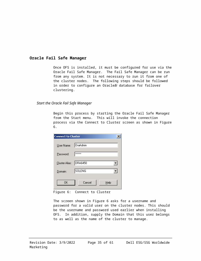
Once OFS is installed, it must be configured for use via the Oracle Fail Safe Manager. The Fail Safe Manager can be run from any system. It is not necessary to run it from one of the cluster nodes. The following steps should be followed in order to configure an Oracle8i database for failover clustering.
Start the Oracle Fail Safe Manager
Begin this process by starting the Oracle Fail Safe Manager from the Start menu. This will invoke the connection process via the Connect to Cluster screen as shown in Figure 6.
Figure 6: Connect to Cluster
The screen shown in Figure 6 asks for a username and password for a valid user on the cluster nodes. This should be the username and password used earlier when installing OFS. In addition, supply the Domain that this user belongs to as well as the name of the cluster to manage.
Revision Date: 5/12/2023 Page 30 of 52 Dell ESG/SSG Worldwide Marketing

Verify Cluster
The first connection to a cluster using Oracle Fail Safe Manager will bring up a dialog box asking to verify the cluster. Click the Verify Cluster button. Review the status report and correct any reported problems before proceeding further.
Once connected to the cluster and the initial cluster verification step has been successfully passed, the main Oracle Fail Safe Manager tree view screen shown here in Figure 7 appears. From this screen choose which components to manage.
Figure 7: Oracle Fail Safe Manager
Revision Date: 5/12/2023 Page 31 of 52 Dell ESG/SSG Worldwide Marketing

Add a new Group
It is necessary to create a new group in order to create an Oracle8i failover cluster. Right click on the group icon and select create. This action will invoke step 1 of the Create Group application as shown in Figure 8. Give the group a unique name and a description.
Figure 8: Create group - Step 1: General
Revision Date: 5/12/2023 Page 32 of 52 Dell ESG/SSG Worldwide Marketing

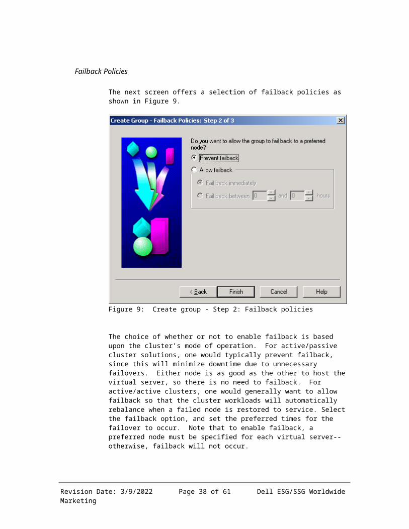
Failback Policies
The next screen offers a selection of failback policies as shown in Figure 9.
Figure 9: Create group - Step 2: Failback policies
The choice of whether or not to enable failback is based upon the cluster’s mode of operation. For active/passive cluster solutions, one would typically prevent failback, since this will minimize downtime due to unnecessary failovers. Either node is as good as the other to host the virtual server, so there is no need to failback. For active/active clusters, one would generally want to allow failback so that the cluster workloads will automatically rebalance when a failed node is restored to service. Select the failback option, and set the preferred times for the failover to occur. Note that to enable failback, a preferred node must be specified for each virtual server--otherwise, failback will not occur.
Finish Creating the Group
The final step is to finish creating the group through screen that shows the choices. Review these choices and click OK to continue with creating the group. Since a group must have a virtual address before resources can be added, the program will prompt to add a virtual address. Click Yes to create the address.
Revision Date: 5/12/2023 Page 33 of 52 Dell ESG/SSG Worldwide Marketing

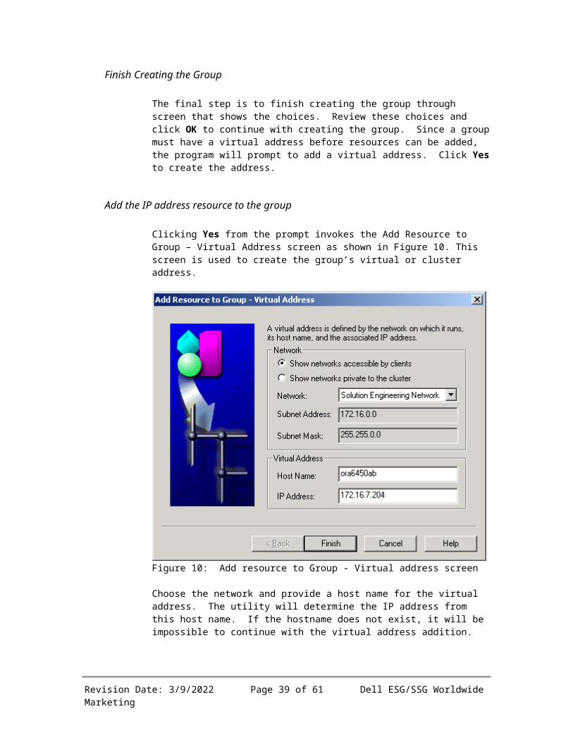
Add the IP address resource to the group
Clicking Yes from the prompt invokes the Add Resource to Group – Virtual Address screen as shown in Figure 10. This screen is used to create the group’s virtual or cluster address.
Figure 10: Add resource to Group - Virtual address screen
Choose the network and provide a host name for the virtual address. The utility will determine the IP address from this host name. If the hostname does not exist, it will be impossible to continue with the virtual address addition.
Note: This is the same virtual server host name that added to the hosts file in Post-installation Step 1 on page 22.
Finish Adding the Virtual Address
Finish Adding the Virtual Address screen prompts to review the choices before completing the addition.
Add the Oracle8i database to the group
Once the group is created and the virtual address is added, it is time to cluster an Oracle8i database. This is accomplished by right
Revision Date: 5/12/2023 Page 34 of 52 Dell ESG/SSG Worldwide Marketing
clicking on the group icon and selecting Add Resource to Group. This allows various different resources to be added to the group as shown in Figure 11. Select Oracle Database and make sure that the correct group is selected. Then click Next.
Figure 11: Add resource to group
Revision Date: 5/12/2023 Page 35 of 52 Dell ESG/SSG Worldwide Marketing

Select the database
Figure 12 offers the selection of which Oracle8i database to cluster. If there are several databases on the system, the program offers a choice of which one to use. Once the service name is selected, the Fail Safe management utility will select the rest of the fields. There is the option to change any of the settings, although it is necessary to ensure new values are valid. For example, to change the initialization file location, the file must be moved by hand. Once satisfied with the selections, select Next.
Figure 12: Database identity
Revision Date: 5/12/2023 Page 36 of 52 Dell ESG/SSG Worldwide Marketing

Database Authentication
Next is the prompt to supply internal database authentication information as shown in Figure 13. The default selection is the Internal account. Supply and confirm the password.
Figure 13: Database authentication
Once this step is completed, click Finish. The next screen is the verification screen. If satisfied with the selections, click OK and the database will be added.
Note: Oracle Fail Safe release 3.1.2 (the currently shipping Oracle Fail Safe release) also supports operating system (OS) authentication for database access. The corresponding screen shot in release 3.1.2 is different (to reflect the additional authentication option).
Revision Date: 5/12/2023 Page 37 of 52 Dell ESG/SSG Worldwide Marketing
Adding the database
Once the database addition to the cluster is confirmed, the next steps run are shown in the Adding Resource screen, Figure 14. Once this has completed successfully, the database will be up and running on the virtual server as a highly available cluster resource.
Figure 14: Adding the database
Revision Date: 5/12/2023 Page 38 of 52 Dell ESG/SSG Worldwide Marketing
The Clustered Database
Once this step has completed, the clustered database and clustered listener will appear in the Oracle Fail Safe Manager as shown in Figure 15.
Figure 15: The clustered database
Verify the cluster
At any time the cluster can be verified by selecting the Verify Cluster option from the Troubleshooting menu. This utility will check the validity of the cluster and report any problems.
Revision Date: 5/12/2023 Page 39 of 52 Dell ESG/SSG Worldwide Marketing

Verify the group
To detect potential problems before they affect users, periodically run the Oracle Fail Safe Manager Verify Group command. For example, if adding a new tablespace and disk to the database, the Verify Group command will automatically detect this change and add the new disk to the group that contains the database.
Revision Date: 5/12/2023 Page 40 of 52 Dell ESG/SSG Worldwide Marketing

Section 9Administration and maintenance
An Oracle Fail Safe cluster can be administered both through the Microsoft Cluster Administrator or the Oracle Fail Safe Administrator. However, certain Oracle specific functions can only be configured via the Oracle Fail Safe Administrator. Because of this, Dell recommends that all administration of the Oracle Fail Safe cluster be done via the Oracle Fail Safe Manager.
Cluster operation and administration
The Oracle Fail Safe Manager can be installed on any system on the network. It is not necessary to run the Oracle Fail Safe Manager on a cluster node. The Fail Safe Manager can be installed by selecting the Client Only installation option when installing OFS. This will install the Oracle Fail Safe Manager and the Oracle Fail Safe documentation.
The Oracle Fail Safe Manager is invoked from the Start menu. After invoking the Fail Safe Manager, supply a username and password. In addition, the Cluster Alias should be defined as well as the name of the Domain that these systems reside in. Once these have been entered, the Oracle Fail Safe Manager will appear as shown in Figure 16.
Revision Date: 5/12/2023 Page 41 of 52 Dell ESG/SSG Worldwide Marketing

Figure 16: Oracle Fail Safe Manager
The navigation pane is on the left and the details pane is on the right. In order to view the Oracle8i database group that was previously created, select that group. The group name is ora6450ab on the example system. This is shown in Figure 17.
Revision Date: 5/12/2023 Page 42 of 52 Dell ESG/SSG Worldwide Marketing

Figure 17: The Oracle8i Database Group
The Oracle8i database group contains the following resources:
The disk volumes used by the Oracle8i database.
The IP address used by the cluster group.
The Network Name used by the cluster group.
The Oracle8i database itself.
The clustered listener.
In addition, the node that the cluster is currently running on appears. From here is the option to perform the cluster maintenance tasks.
Revision Date: 5/12/2023 Page 43 of 52 Dell ESG/SSG Worldwide Marketing

Moving the Oracle services to another node (planned failover)
Moving the Oracle service to another node can be accomplished from the main screen of the Oracle Fail Safe Manager. Select the group and either:
Highlight the group and select Groups→Move to a Different Node… from the menu at the top of the application.
Right click on the group and select Move to a Different Node from the menu as shown in Figure 18.
Figure 18: Group selection menu
After selecting this option, the Confirm Move Group dialog box will appear. This dialog box warns that moving the Oracle group will result in the database being shut down and restarted on the other node. This dialog box is shown in Figure 19.
Revision Date: 5/12/2023 Page 44 of 52 Dell ESG/SSG Worldwide Marketing

Figure 19: Confirm move group dialog box
If shutting down the database is not the desired result, click No. However, to shut down the database and to move it to the other node, click Yes. Clicking Yes will begin the move. The Moving group screen will appear showing the progress of the move. This screen is shown in Figure 20.
Figure 20: Moving group screen
This screen follows the progress of the move. Once the move has completed, status of the group can be viewed in the Oracle Fail Safe Manager.
Shutting down the cluster
The Oracle8i database should only be shut down using the Oracle Fail Safe Manager. Shutting down the database is accomplished by
Revision Date: 5/12/2023 Page 45 of 52 Dell ESG/SSG Worldwide Marketing

bringing the group or just the database resource within the group offline. In order to bring the group offline do either of the following:
Highlight the group and select Groups→Take Offline from the menu at the top of the application.
Right click on the group and select Take Offline
This will shut down the Oracle database and temporarily disable high availability monitoring by the cluster software. If issuing a shutdown command within the Oracle instance (or simply stopping the Oracle database service), MSCS will detect this as a database failure and immediately attempt to restart the database. Oracle8i should be shutdown within the OFS Manager utility to avoid automatically restarting the instance.
Oracle8i operation and administration
Operationally, Oracle8i is no different whether running on a Fail Safe cluster or not. Oracle8i is still administered via the DBA Studio or Oracle Enterprise Manager (OEM). Oracle8i databases can be created or modified via these utilities or the Oracle Database Configuration Assistant. When creating a new Oracle8i database, it is required that the control files, redo log files, data files and initialization parameter files are all created on the shared storage subsystem. Since the Oracle8i instance and database must be created and functional before it can be clustered it is easy to create a database that cannot be clustered because of these requirements. In order to avoid this problem, be sure that the clustered drive(s) are used for control files, redo log files and data files. As mentioned earlier, the redo log files and data files should reside on different shared disk volumes.
Configuring Net8
Once the Oracle8i database is up and running in a clustered environment, it is necessary to configure the clients in order to access the clustered database. This can be accomplished by adding the clustered database’s service name into the local tnsnames file or the Oracle names server. This can be done using the Oracle Net8 Configuration Assistant.
Revision Date: 5/12/2023 Page 46 of 52 Dell ESG/SSG Worldwide Marketing

Section 10Post-Installation Testing
The best way to test the cluster is to connect using SQL*Plus. Connect into the system as INTERNAL or SYS and execute the following query:
SELECT * FROM v$instance
The results of this query include the field HOST_NAME. The value of this field will tell which node the clustered Oracle8i instance is currently running on. Fail over the cluster and try this again. It is now running on the second node.
Note: The transparent application failover (TAF) demo program installed with Oracle Fail Safe Manager in the <Oracle_Home>\fs\fsmgr\sample directory can also be used to test failover capabilities.
Revision Date: 5/12/2023 Page 47 of 52 Dell ESG/SSG Worldwide Marketing

Section 11ConclusionBest Practices and Key Findings
Oracle Fail Safe (OFS) in conjunction with Microsoft Cluster Services (MSCS) forms a high-availability, failover cluster. A failover cluster allows the cluster-aware application to migrate from one system or node to a standby node. This increases the availability of the total system by allowing recovery to complete more quickly. In addition, if a hardware problem is at fault, the standby node will take over and continue functioning until the primary node can be repaired.
Oracle Fail Safe and Microsoft Cluster Services do not provide for continuous uptime. In the event of a system failure that requires failover, all connections into the database are lost. It is up to the client application or user to reconnect into the clustered database.
Client applications that layer over the Oracle Call Interface (OCI) can take advantage of OCI transparent application failover features to automate user reconnections after a failover and to automatically replay any interrupted SELECT statements after the failover.
There are several cases where OFS and MSCS will not be able to recover the system to a functional state:
Storage subsystem failure: OFS and MSCS will restart the Oracle8i instance using a different system, but using the same shared storage subsystem. A failure of the storage subsystem will cause all nodes in the cluster to fail.
Data corruption: If an OS or Oracle program failure corrupts the database, OFS does not help since there is only one database.
User error: A user error that drops a table or database cannot be recovered from using OFS.
OFS, MSCS and fault tolerant storage subsystems are not an excuse to avoid performing effective Oracle8i backups. However, with proper configuration and administration OFS and MSCS can greatly reduce down time and increase availability of an Oracle8i database. OFS in conjunction with a good backup/recovery and disaster survival plan will add to the stability and up time of the overall system.
Conclusion
This paper has described the functionality and usefulness of Oracle Fail Safe and Microsoft Cluster Services that form a highly available, failover cluster. This paper describes how to plan, configure, install
Revision Date: 5/12/2023 Page 48 of 52 Dell ESG/SSG Worldwide Marketing

and manage an OFS cluster. The use of the OFS cluster can reduce system downtime by restoring the system to a running state as soon as possible.
Contacts
For questions about this paper or the implementation of Oracle Fail Safe with Dell PowerEdge Cluster Systems, please contact your Dell sales representative. More Oracle Fail Safe information including technical white papers and the latest Oracle Fail Safe documentation and software is available through the Oracle Technology Network at http://technet.oracle.com/tech/nt/failsafe/. For comments and feedback, please send email to: [email protected].
Solution Engineering DepartmentEnterprise Systems Group/Storage Systems Group
Dell Computer CorporationOne Dell Way
Round Rock, Texas USA 78682+1-(800) WWW-DELL (999-3355)
or +1-(512) [email protected]
www.dell.com
Dell, PowerEdge, and PowerVault are trademarks of Dell Computer Corporation. Oracle and Oracle8i are either registered trademarks or trademarks of Oracle Corporation. Microsoft, Windows and Microsoft Cluster Services are either registered trademarks or trademarks of Microsoft Corporation. Other trademarks and trade names may be used in this document to refer to either the entities claiming the marks and names or their products. Dell disclaims proprietary interest in the marks and names of others.
©Copyright 2001 Dell Computer Corporation. All rights reserved. Reproduction in any manner whatsoever without the express written permission of Dell Computer Corporation is strictly forbidden. For more information, contact Dell. Dell cannot be responsible for errors in typography or photography.
Information in this document is subject to change without notice.
Revision Date: 5/12/2023 Page 49 of 52 Dell ESG/SSG Worldwide Marketing

Appendix A: Vendor Information
Oracle Corporation
Oracle Corporation (NASDAQ: ORCL) is a leading worldwide supplier of software for information management, and the world's second largest independent software company. With annual revenues of more than $10.1 billion, the company offers its database, tools and application products, along with related consulting, education, and support services, in more than 145 countries around the world. Information about Oracle and its products can be obtained on the World Wide Web at www.oracle.com.
Dell Computer Corporation
Dell Computer Corporation (NASDAQ: DELL) is the world's leading direct computer systems company, based on revenues of $32 billion for the past four quarters, and is a premier provider of products and services required for customers to build their Internet infrastructures. The company ranks No. 48 on the Fortune 500, No. 154 on the Fortune Global 500 and No. 7 on the Fortune "Global Most Admired" list of companies. Dell designs, manufactures and customizes products and services to customer requirements, and offers an extensive selection of software and peripherals. Information on Dell and its products can be obtained on the World Wide Web at www.dell.com.
Intel Corporation
Intel Corporation (NASDAQ: INTC) is one of the world's largest chipmakers, a leading manufacturer of computer, networking and communications products, and a premier supplier of building blocks for the worldwide Internet economy. Servers based on Intel® Pentium III Xeon™ and Itanium™ processors deliver cost-effective, top performance, reliability and scalability for business applications. All Dell machines used for the testing described in this paper used Intel processors. Additional information about Intel is available at www.intel.com/pressroom.
Microsoft Corporation
Founded in 1975, Microsoft (NASDAQ: MSFT) is a worldwide leader in software, services and Internet technologies for personal and business computing. For more information about Microsoft see www.microsoft.com.
Revision Date: 5/12/2023 Page 50 of 52 Dell ESG/SSG Worldwide Marketing

Appendix B: Reference Documents
“Dell PowerEdge Cluster SE100, SE200, and SL200 Platform Guide” for SCSI systems.
“Dell PowerEdge Cluster FE100/FL100 Platform Guide” for fiber channel systems.
Oracle Fail Safe Installation Guide Release 3.1.1 for Windows NT and Windows 2000
Revision Date: 5/12/2023 Page 51 of 52 Dell ESG/SSG Worldwide Marketing

Appendix C: Glossary Cluster-aware – A cluster-aware application provides functionality that allows it to take advantage of the failover features provided by clustering.
ESEM – Enclosure Services Expander Module (a type of SCSI Management Module) Failback - Once a failover occurs, the failed system may be restored, brought back online, and processing may be resumed by switching back to the restored system – this is called failback.
Failover – a way to attain high server availability such that if one system fails or is purposely taken offline, an application can switch to a second, clustered system – this switch is known as a failover. Failover minimizes system downtime.
HBA - Host bus adapter
MSCS – Microsoft Cluster Services
NIC – Network Interface Card
OFS – Oracle Fail Safe
Quorum disk – Disk space used to store cluster configuration database checkpoints and log files that help manage the cluster.
RAID – Redundant Array of Inexpensive Disks
SEMM – SCSI Expander Management Module (a type of SCSI Management Module)
Subnet – The part of the IP address that includes the network prefix and subnet number, but not the host number.
Virtual address - A network address at which resources in a group can be accessed, regardless of the cluster node hosting those resources. A virtual address on an MSCS cluster consists of a network name and associated IP address.
Virtual server - A group with one or more virtual addresses.
WebDB – Now called Oracle Portal (formerly WebDB). Part of the Oracle applications that help develop and deploy enterprise Web portals.
Revision Date: 5/12/2023 Page 52 of 52 Dell ESG/SSG Worldwide Marketing