Embed Size (px)
Citation preview
WFC- SC
Chiller
2 Installation
WFC-SC5
Version 8-1
- 1 -
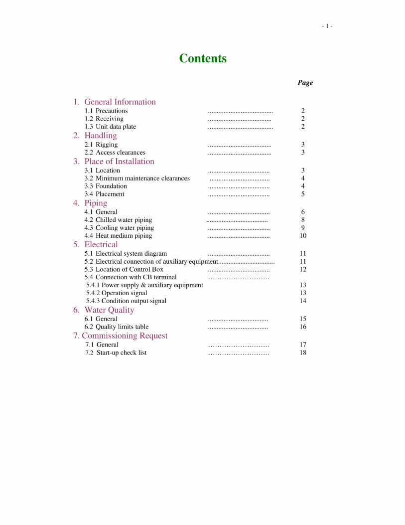
Contents Page
1. General Information
1.1 Precautions ...................................... 2
1.2 Receiving ..................................... 2
1.3 Unit data plate ...................................... 2
2. Handling 2.1 Rigging ..................................... 3
2.2 Access clearances ..................................... 3
3. Place of Installation 3.1 Location .................................... 3
3.2 Minimum maintenance clearances ................................... 4 3.3 Foundation .................................... 4
3.4 Placement .................................... 5
4. Piping 4.1 General .................................... 6
4.2 Chilled water piping .................................... 8
4.3 Cooling water piping .................................... 9
4.4 Heat medium piping .................................... 10
5. Electrical 5.1 Electrical system diagram .................................... 11
5.2 Electrical connection of auxiliary equipment................................. 11
5.3 Location of Control Box .................................... 12 5.4 Connection with CB terminal ………………………
5.4.1 Power supply & auxiliary equipment 13
5.4.2 Operation signal 13
5.4.3 Condition output signal 14
6. Water Quality 6.1 General ................................... 15
6.2 Quality limits table ................................... 16
7. Commissioning Request 7.1 General ……………………… 17
7.2 Start-up check list ……………………… 18
- 2 -
General Information. 1.1 Precautions The chiller should be installed by trained and qualified personnel who are familiar
with absorption machinery. All precautions in these instructions, on tags and on labels
attached to the chiller must be strictly observed to ensure safety of personnel and
continuance of the warranty validation.
Each absorption chiller has been evacuated, charged with lithium bromide and water,
and tested prior to leaving the factory. After the equipment has been installed, a
Yazaki authorized service agent will check the installation and supervise the initial
commissioning of the machine.
It is important to note that the warranty applying to the Yazaki chiller will become
void if the following restrictions are not fully observed.
1. Do not open any service valves because such action will result in loss of vacuum.
2. Always handle the equipment with care and in an upright position, do not drop or
subject the machine to side impact.
3. Do not attempt to start the system without supervision from a Yazaki authorized
service agent.
1.2 Receiving When the absorption chiller is delivered to site, inspect it for transit damage. Should
any damage have occurred, do not proceed with the installation until the Yazaki
distributor has been notified and instruction to continue has been obtained.
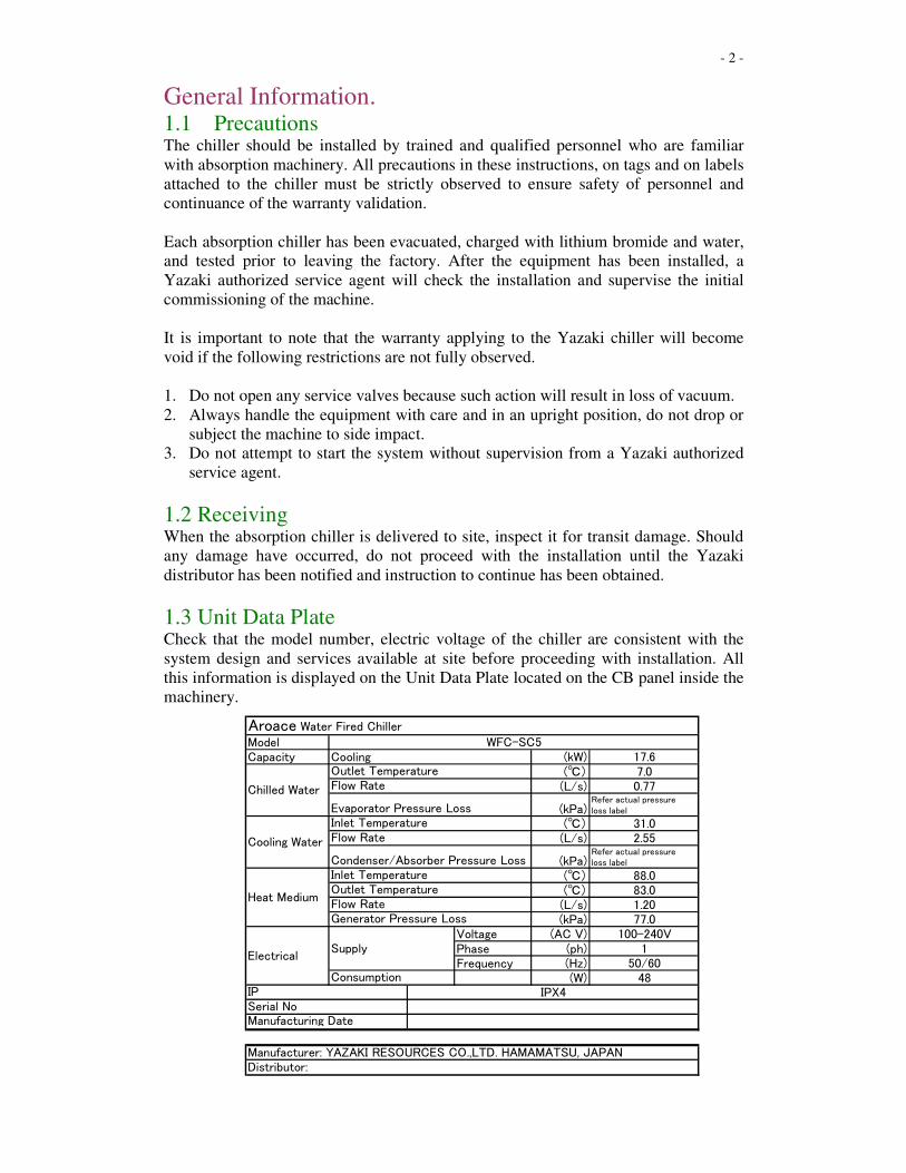
1.3 Unit Data Plate Check that the model number, electric voltage of the chiller are consistent with the
system design and services available at site before proceeding with installation. All
this information is displayed on the Unit Data Plate located on the CB panel inside the
machinery.
ModelCapacity (kW) 17.6
(℃) 7.0(L/s) 0.77
(kPa)Refer actual pressureloss label
(℃) 31.0(L/s) 2.55
(kPa)Refer actual pressureloss label
(℃) 88.0(℃) 83.0(L/s) 1.20(kPa) 77.0
Voltage (AC V) 100-240VPhase (ph) 1Frequency (Hz) 50/60
(W) 48
Aroace Water Fired Chiller
Chilled Water
Cooling Water
Heat Medium
Electrical
CoolingWFC-SC5
Supply
Consumption
Flow RateGenerator Pressure Loss
Flow Rate
Outlet TemperatureFlow Rate
Evaporator Pressure LossInlet Temperature
Manufacturer: YAZAKI RESOURCES CO.,LTD. HAMAMATSU, JAPANDistributor:
Condenser/Absorber Pressure LossInlet TemperatureOutlet Temperature
Serial NoManufacturing Date
IP IPX4
- 3 -
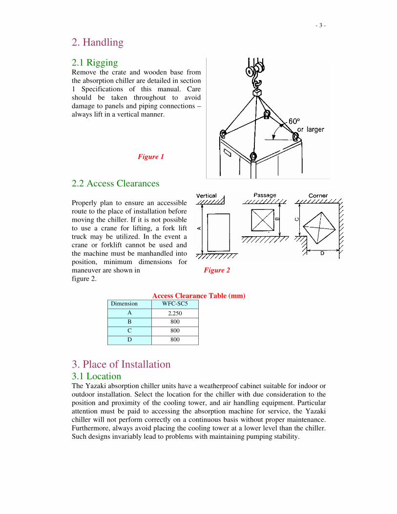
2. Handling
2.1 Rigging Remove the crate and wooden base from
the absorption chiller are detailed in section
1 Specifications of this manual. Care
should be taken throughout to avoid
damage to panels and piping connections –
always lift in a vertical manner.
Figure 1
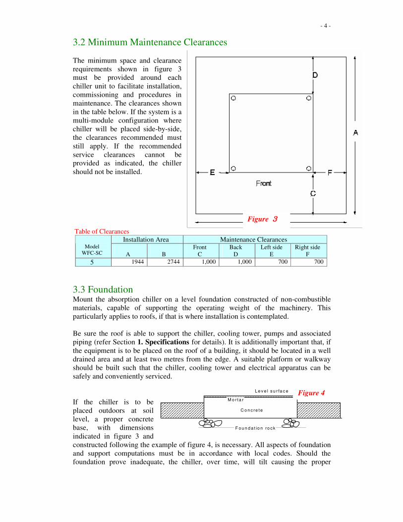
2.2 Access Clearances Properly plan to ensure an accessible
route to the place of installation before
moving the chiller. If it is not possible
to use a crane for lifting, a fork lift
truck may be utilized. In the event a
crane or forklift cannot be used and
the machine must be manhandled into
position, minimum dimensions for
maneuver are shown in Figure 2
figure 2.
Access Clearance Table (mm) Dimension WFC-SC5
A 2,250
B 800
C 800
D 800
3. Place of Installation 3.1 Location The Yazaki absorption chiller units have a weatherproof cabinet suitable for indoor or
outdoor installation. Select the location for the chiller with due consideration to the
position and proximity of the cooling tower, and air handling equipment. Particular
attention must be paid to accessing the absorption machine for service, the Yazaki
chiller will not perform correctly on a continuous basis without proper maintenance.
Furthermore, always avoid placing the cooling tower at a lower level than the chiller.
Such designs invariably lead to problems with maintaining pumping stability.
- 4 -
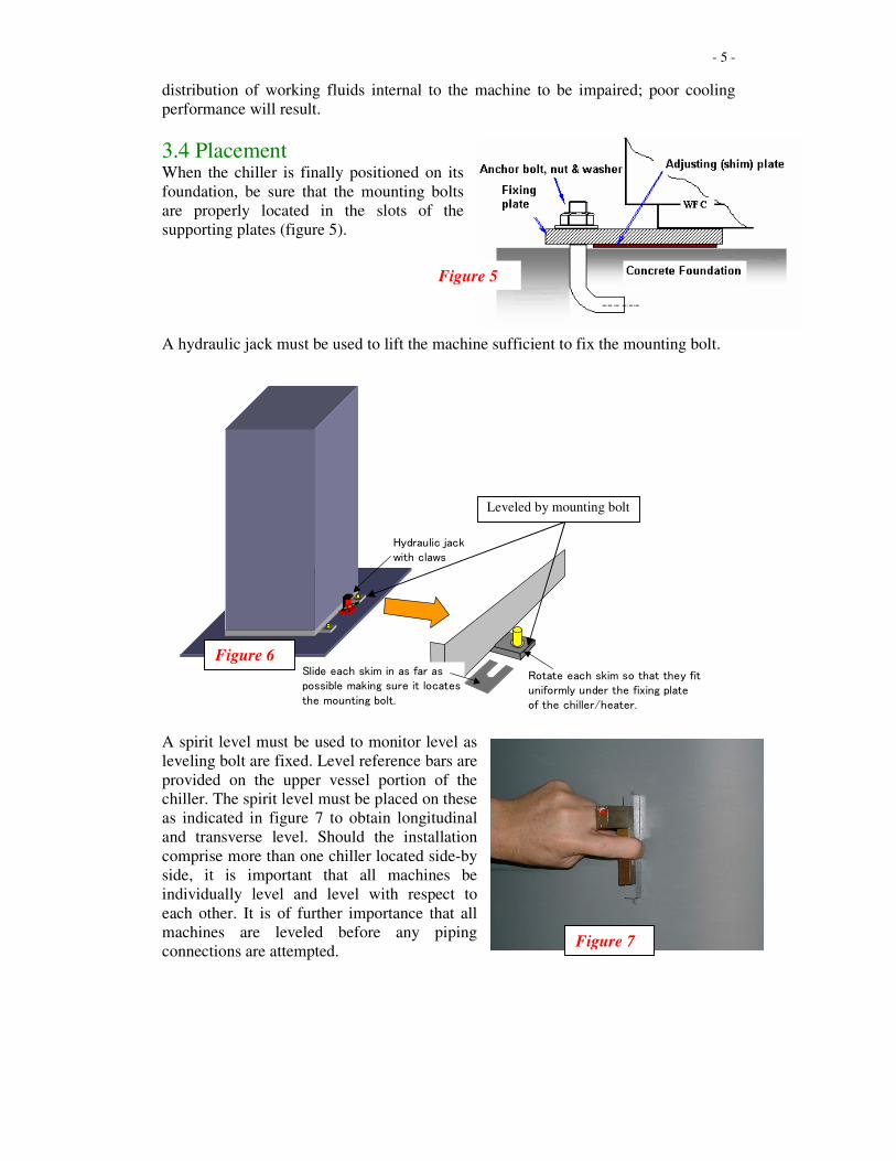
3.2 Minimum Maintenance Clearances
The minimum space and clearance
requirements shown in figure 3
must be provided around each
chiller unit to facilitate installation,
commissioning and procedures in
maintenance. The clearances shown
in the table below. If the system is a
multi-module configuration where
chiller will be placed side-by-side,
the clearances recommended must
still apply. If the recommended
service clearances cannot be
provided as indicated, the chiller
should not be installed.
F
i
g
u
r
Table of Clearances
Installation Area Maintenance Clearances Model
WFC-SC
A
B
Front
C
Back
D
Left side
E
Right side
F
5 1944 2744 1,000 1,000 700 700
3.3 Foundation Mount the absorption chiller on a level foundation constructed of non-combustible
materials, capable of supporting the operating weight of the machinery. This
particularly applies to roofs, if that is where installation is contemplated.
Be sure the roof is able to support the chiller, cooling tower, pumps and associated
piping (refer Section 1. Specifications for details). It is additionally important that, if
the equipment is to be placed on the roof of a building, it should be located in a well
drained area and at least two metres from the edge. A suitable platform or walkway
should be built such that the chiller, cooling tower and electrical apparatus can be
safely and conveniently serviced.
If the chiller is to be
placed outdoors at soil
level, a proper concrete
base, with dimensions
indicated in figure 3 and
constructed following the example of figure 4, is necessary. All aspects of foundation
and support computations must be in accordance with local codes. Should the
foundation prove inadequate, the chiller, over time, will tilt causing the proper
F o u n d a t io n ro c k
C o n c re te
M o r ta r
L e v e l s u r fa c e Figure 4
Figure 3333
- 5 -
distribution of working fluids internal to the machine to be impaired; poor cooling
performance will result.
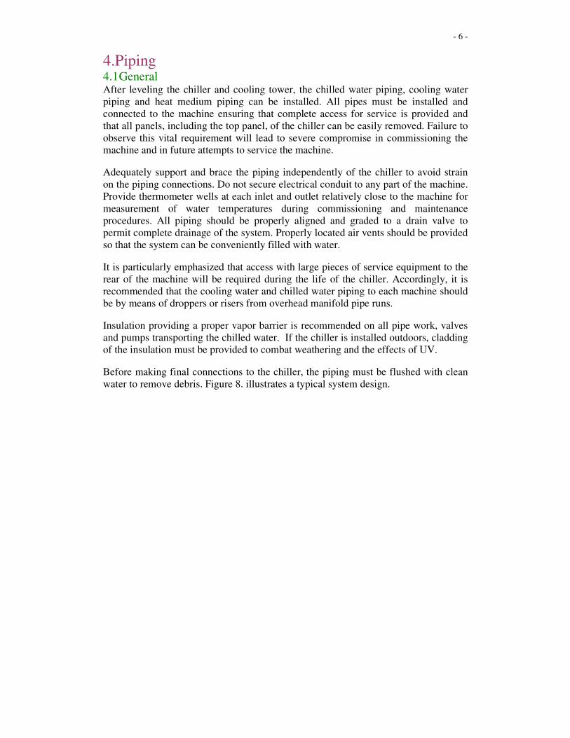
3.4 Placement When the chiller is finally positioned on its
foundation, be sure that the mounting bolts
are properly located in the slots of the
supporting plates (figure 5).
A hydraulic jack must be used to lift the machine sufficient to fix the mounting bolt.
A spirit level must be used to monitor level as
leveling bolt are fixed. Level reference bars are
provided on the upper vessel portion of the
chiller. The spirit level must be placed on these
as indicated in figure 7 to obtain longitudinal
and transverse level. Should the installation
comprise more than one chiller located side-by
side, it is important that all machines be
individually level and level with respect to
each other. It is of further importance that all
machines are leveled before any piping
connections are attempted.
Slide each skim in as far aspossible making sure it locatesthe mounting bolt.
Rotate each skim so that they fituniformly under the fixing plateof the chiller/heater.
Hydraulic jackwith claws
Leveled by mounting bolt
Figure 6
Figure 7
Figure 5
- 6 -
4.Piping
4.1 General After leveling the chiller and cooling tower, the chilled water piping, cooling water
piping and heat medium piping can be installed. All pipes must be installed and
connected to the machine ensuring that complete access for service is provided and
that all panels, including the top panel, of the chiller can be easily removed. Failure to
observe this vital requirement will lead to severe compromise in commissioning the
machine and in future attempts to service the machine.
Adequately support and brace the piping independently of the chiller to avoid strain
on the piping connections. Do not secure electrical conduit to any part of the machine.
Provide thermometer wells at each inlet and outlet relatively close to the machine for
measurement of water temperatures during commissioning and maintenance
procedures. All piping should be properly aligned and graded to a drain valve to
permit complete drainage of the system. Properly located air vents should be provided
so that the system can be conveniently filled with water.
It is particularly emphasized that access with large pieces of service equipment to the
rear of the machine will be required during the life of the chiller. Accordingly, it is
recommended that the cooling water and chilled water piping to each machine should
be by means of droppers or risers from overhead manifold pipe runs.
Insulation providing a proper vapor barrier is recommended on all pipe work, valves
and pumps transporting the chilled water. If the chiller is installed outdoors, cladding
of the insulation must be provided to combat weathering and the effects of UV.
Before making final connections to the chiller, the piping must be flushed with clean
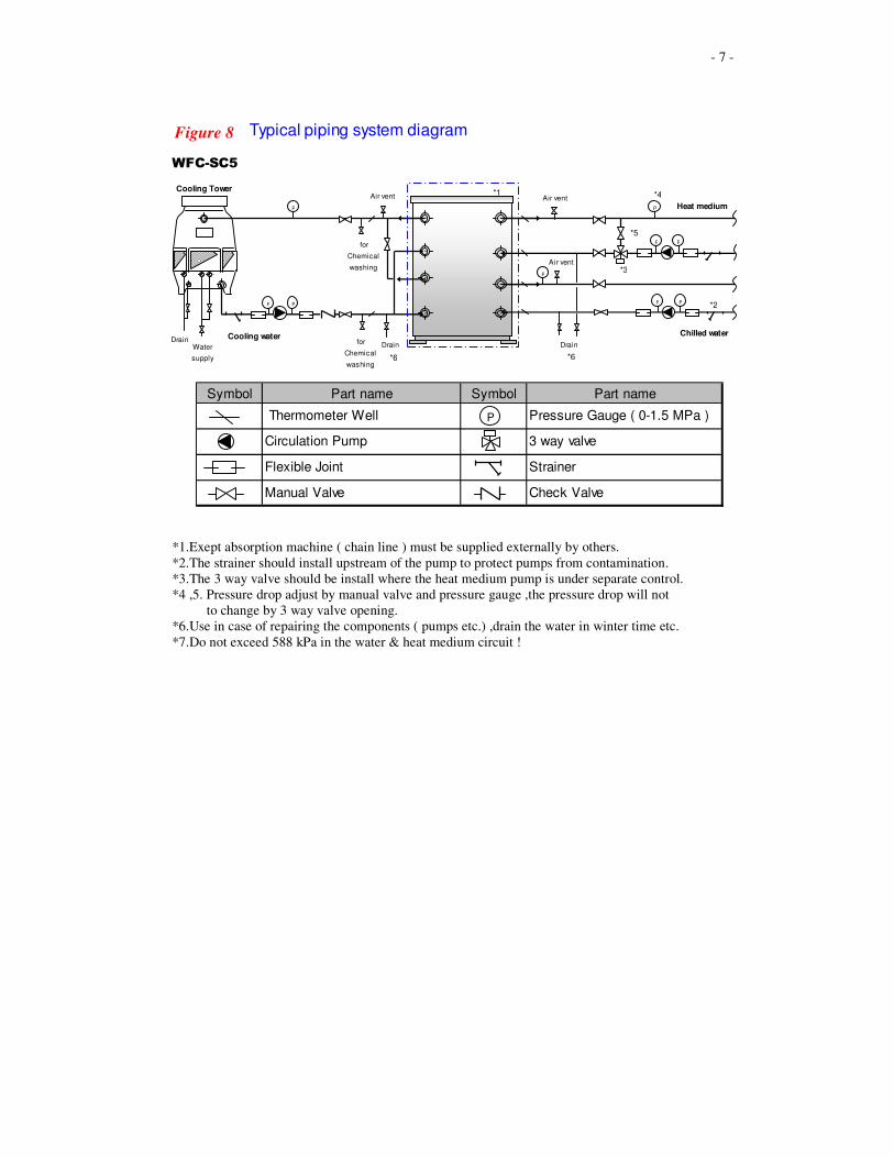
water to remove debris. Figure 8. illustrates a typical system design.
- 7 -
*1.Exept absorption machine ( chain line ) must be supplied externally by others.
*2.The strainer should install upstream of the pump to protect pumps from contamination.
*3.The 3 way valve should be install where the heat medium pump is under separate control.
*4 ,5. Pressure drop adjust by manual valve and pressure gauge ,the pressure drop will not
to change by 3 way valve opening.
*6.Use in case of repairing the components ( pumps etc.) ,drain the water in winter time etc.
*7.Do not exceed 588 kPa in the water & heat medium circuit !
WFC-SC5
Cooling Tower
P P
P P
P
P
Air vent
Air vent
Drain
Chilled water
Heat medium
PP
for
Chemical
washing
Drain
Air vent
P
for
Chemical
washing
DrainWater
supply
Cooling water
Symbol Part name Symbol Part name
Thermometer Well Pressure Gauge ( 0-1.5 MPa )
Circulation Pump 3 way valve
Flexible Joint Strainer
Manual Valve Check Valve
P
*1
*2
*3
*4
*6 *6
*5
Typical piping system diagramFigure 8
- 8 -
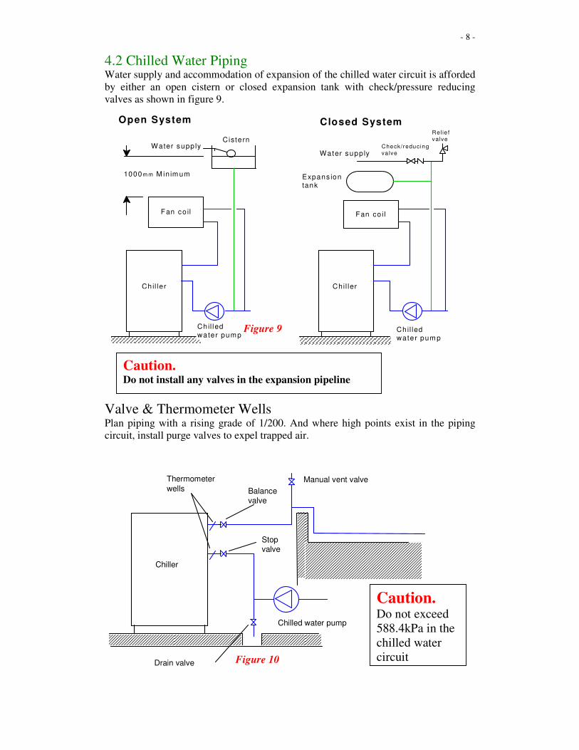
4.2 Chilled Water Piping
Water supply and accommodation of expansion of the chilled water circuit is afforded
by either an open cistern or closed expansion tank with check/pressure reducing
valves as shown in figure 9.
Valve & Thermometer Wells
Plan piping with a rising grade of 1/200. And where high points exist in the piping
circuit, install purge valves to expel trapped air.
Caution. Do not install any valves in the expansion pipeline
Figure 9
Chiller
Chilled water pump
Drain valve
Stop valve
Balance valve
Thermometer wells
Manual vent valve
Caution. Do not exceed
588.4kPa in the
chilled water
circuit Figure 10
Chil ler
Heater
Chil ler-
Heater
Ch il led-ho t water pum p
Fan co il Fan co il
Expans iontank
Closed SystemOpen System
Water supp lyCiste rn
1000m m M in im um
Water supp lyCheck/reducing va lve
Re lie f va lve
Chil led-ho t
water pump
- 9 -
A balance valve should be installed in the chilled water outlet and a stop valve should
be installed in the chilled water inlet. Both valves along with thermometer wells
should be placed in close proximity to the chiller, refer figure 10.
After thoroughly testing for leaks, insulate the piping circuit ensuring an adequate
vapor barrier is obtained. Be sure the insulation allows proper access to all
thermometer wells and hand valves. Be also sure that the chiller panels are not
restricted by the insulation.
If the equipment is installed outdoors and subject to freezing ambient conditions, trace
heating of the pipes under the insulation may be considered. If glycol solutions are
contemplated, it is important that inhibitors are in solution to protect copper tubes
internal to the machine. It is further most important to understand that cooling
capacity of the chiller will be degraded as concentrations of the glycol solutions
increase – it must be noted that there is limited flow rate increase allowance for the
chilled water circuit.
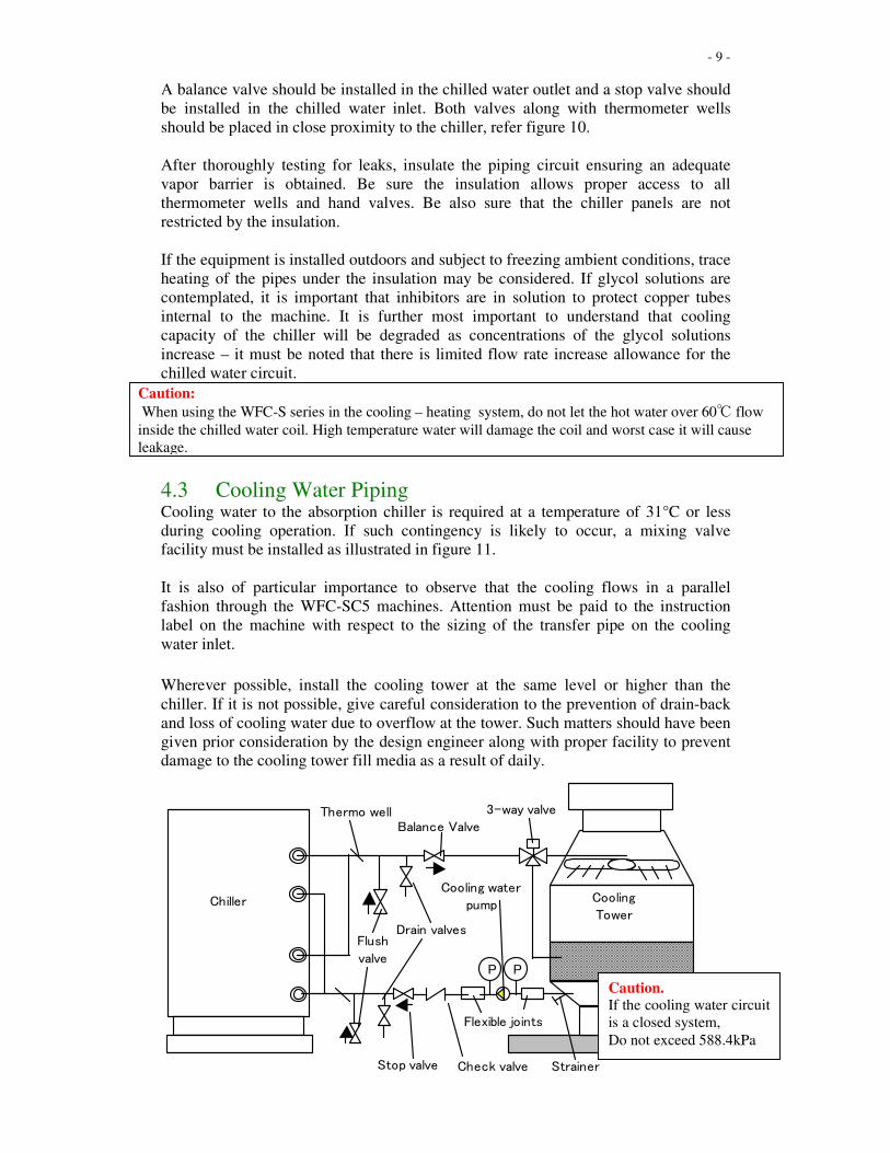
4.3 Cooling Water Piping Cooling water to the absorption chiller is required at a temperature of 31°C or less
during cooling operation. If such contingency is likely to occur, a mixing valve
facility must be installed as illustrated in figure 11.
It is also of particular importance to observe that the cooling flows in a parallel
fashion through the WFC-SC5 machines. Attention must be paid to the instruction
label on the machine with respect to the sizing of the transfer pipe on the cooling
water inlet.
Wherever possible, install the cooling tower at the same level or higher than the
chiller. If it is not possible, give careful consideration to the prevention of drain-back
and loss of cooling water due to overflow at the tower. Such matters should have been
given prior consideration by the design engineer along with proper facility to prevent
damage to the cooling tower fill media as a result of daily.
Stop valve
P P
Cooling water
pump
3-way valve
Check valve
Drain valves
Cooling
TowerChiller
Flexible joints
Strainer
Flush
valve
Thermo wellBalance Valve
Caution. If the cooling water circuit
is a closed system,
Do not exceed 588.4kPa
Caution:
When using the WFC-S series in the cooling – heating system, do not let the hot water over 60℃ flow
inside the chilled water coil. High temperature water will damage the coil and worst case it will cause
leakage.
- 10 -
A balance valve should be installed in the cooling water inlet and a stop valve
installed in the cooling water outlet. Both valves should be placed in close proximity
to the chiller along with thermometer wells for temperature measurement.
Additionally, drain (flush) valves should be installed between the balance/stop valves
and the machine to allow chemical washing of the absorber-condenser coils (see
figure 11)
If it is indicated that none of the aforementioned matters have been adequately catered
for, the authorized Yazaki distributor should be contacted for advice. Do not ignore
these contingencies; operating the machine without proper safeguards for both the
cooling tower and the chiller will void the chiller warranty.
4.4 Heat Medium Piping The heat medium pipe work will most likely be a closed system. Accordingly, since
temperature of the heat medium may operate as high as 95°C, with a standard inlet
88°C, care should be taken with the expansion device. All considerations with respect
to hand valves in the other water circuits also apply to the heat medium circuit.
Depending on the type of system used to source the hot water to operate the chiller, a
diverting valve in the heat medium circuit may be required. Should the decision be
made to use a three way valve, the approach to control outlined in the following
electrical circuit should be adopted.
Caution. Do not exceed 588.4kPa in the heat medium circuit of the absorption
chiller
- 11 -
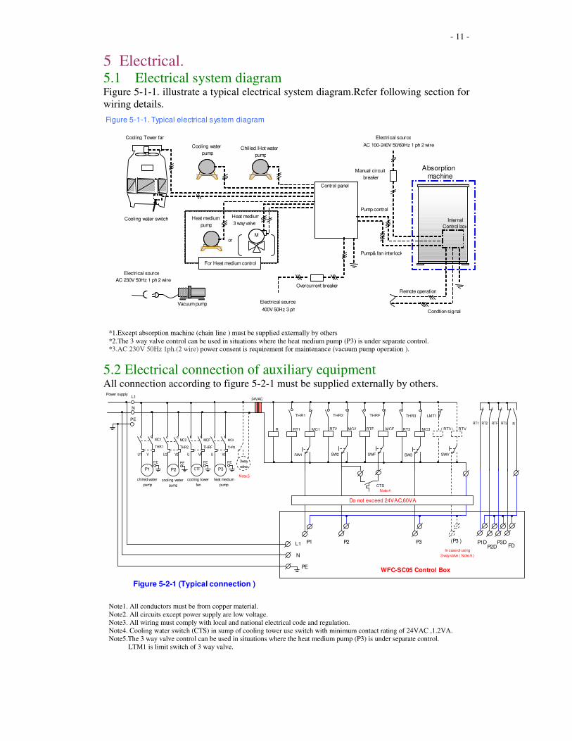
5 Electrical. 5.1 Electrical system diagram Figure 5-1-1. illustrate a typical electrical system diagram.Refer following section for
wiring details.
*1.Except absorption machine (chain line ) must be supplied externally by others
*2.The 3 way valve control can be used in situations where the heat medium pump (P3) is under separate control. *3.AC 230V 50Hz 1ph.(2 wire) power consent is requirement for maintenance (vacuum pump operation ).
5.2 Electrical connection of auxiliary equipment All connection according to figure 5-2-1 must be supplied externally by others.
Note1. All conductors must be from copper material.
Note2. All circuits except power supply are low voltage.
Note3. All wiring must comply with local and national electrical code and regulation.
Note4. Cooling water switch (CTS) in sump of cooling tower use switch with minimum contact rating of 24VAC ,1.2VA.
Note5.The 3 way valve control can be used in situations where the heat medium pump (P3) is under separate control.
LTM1 is limit switch of 3 way valve.
MC1R
24VAC
cooling water
pump
chilled water
pump
cooling tower
fan
heat medium
pump
Note.4
WFC-SC05 Control Box
In case of using
3 way valve ( Note.5 )
CTS
RT1
3way
valve
RT1
THR1
SW1
RT2
THR2
SW2
RTF
THRF
SWF
RT3
THR3
SW3
( RT3 )
LMT1
SWV
RTV
Do not exceed 24VAC,60VA
MC3MCFMC2
RT2 RTF RT3 R
P1 P2 CTF P3
L1
N
PE
PEPEPE PE
U1 V U2 V2 U VF U V3
THR1
MC1
THR2
MC2
THRF
MCF
THR3
MC3
Note.5
Figure 5-2-1 (Typical connection )
P1 P2 P3 (P3 ) P1DP2D
P3DFDL1
N
PE
Power supply
Cooling Tower fan
Control panel
Absorption machine
Internal
Control box
Remote operation
Condtion signal
Overcurrent breaker
Manual circuit
breaker
Pump control
Pump& fan interlock
Electrical source
400V 50Hz 3 ph
Mor
For Heat medium control
Heat medium
pump
Heat medium
3 way valveCooling water switch
Cooling water
pumpChilled /Hot water
pump
Figure 5-1-1. Typical electrical system diagram
Electrical source
AC 100-240V 50/60Hz 1 ph 2 wire
Electrical source
AC 230V 50Hz 1 ph 2 wire
Vacuum pump
- 12 -
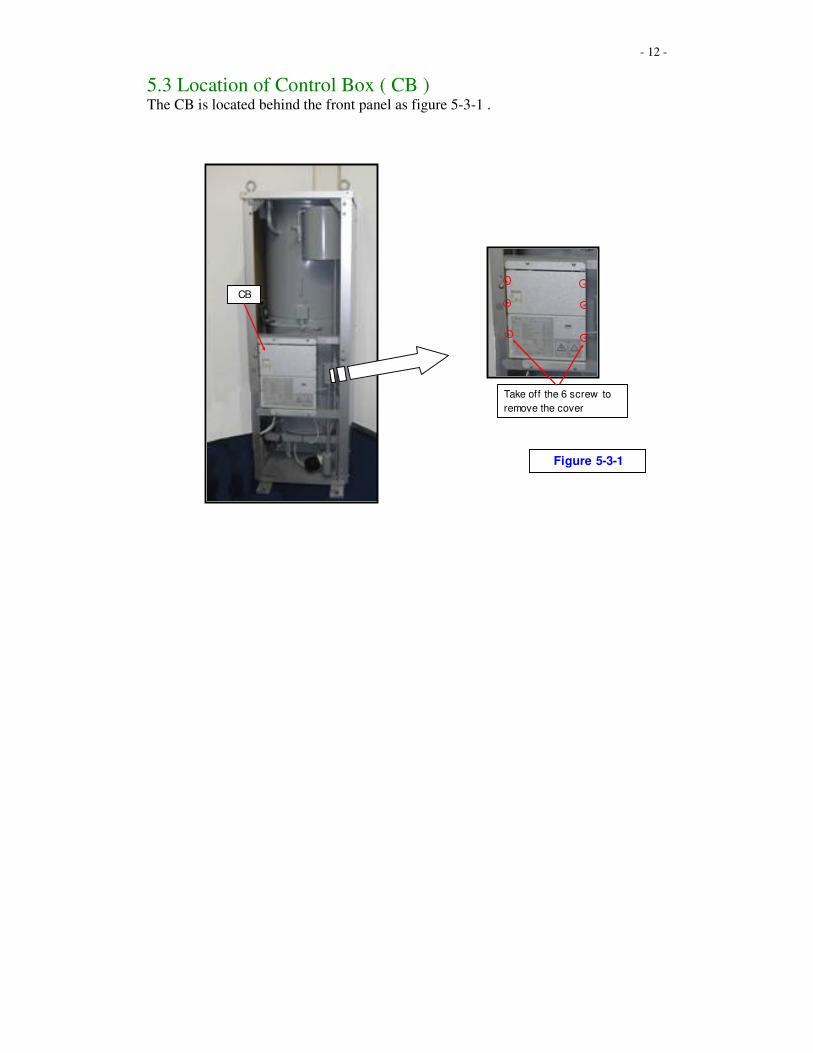
5.3 Location of Control Box ( CB ) The CB is located behind the front panel as figure 5-3-1 .
Take off the 6 screw to
remove the cover
CB
Figure 5-3-1
- 13 -
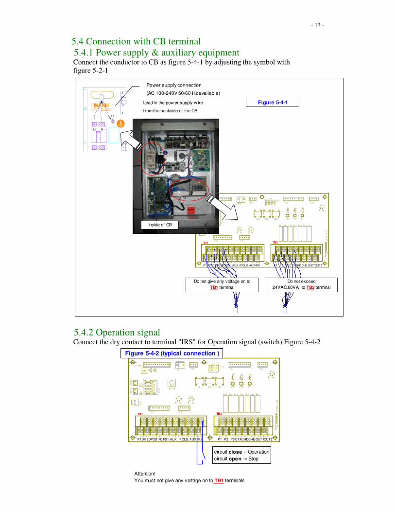
5.4 Connection with CB terminal
5.4.1 Power supply & auxiliary equipment Connect the conductor to CB as figure 5-4-1 by adjusting the symbol with
figure 5-2-1
5.4.2 Operation signal Connect the dry contact to terminal "IRS" for Operation signal (switch).Figure 5-4-2
Attention!
You must not give any voltage on to TB1 terminals
PN7
TB1
1 2 3 4 5 6 7 8 9 10 1 2 3 4 5 6 7 8
TB2
RY1 RY2 RY3 RY4 RY5 RY6 RY7
51
CN3
1 10
CN4
1 4
CN6
DB1 DB2 DB3
1 3
CN5
1 12
1 9
CN2
12
12
16
PN1
PN11
PN12
CN11
PN2
R1
R2
R3
CNSP
L1L2
L3L4
R4
R7
R5
R6
R8
R9
PN4
1 2
1 2
PN6
1 2
PN5
RSTSW
SC0
5-I/O
CHD CHE PL
P1DP2DP3D FDFS1 AUX IFCLS AUX IRS P1 P2 P3 CTFCHDCHE OUT1OUT2
TB1 TB2
Figure 5-4-2 (typical connection )
circuit close = Operation
circuit open = Stop
PN7
TB1
1 2 3 4 5 6 7 8 9 10 1 2 3 4 5 6 7 8
TB2
RY1 RY2 RY3 RY4 RY5 RY6 RY7
51
CN3
1 10
CN4
1 4
CN6
DB1 DB2 DB3
1 3
CN5
1 12
1 9
CN2
12
12
16
PN1
PN11
PN12
CN11
PN2
R1
R2
R3
CNSP
L1
L2
L3L4
R4
R7
R5
R6
R8
R9
PN4
1 2
1 2
PN6
1 2
PN5
RSTSW
SC05-I/O
CHD CHE PL
Figure 5-4-1
Inside of CB
Power supply connection
(AC 100-240V 50/60 Hz available)
Lead in the pow er supply w ire
from the backside of the CB.
P1DP2D P3D FDFS1 AUX IFCLS AUXIRS P1 P2 P3 CTFCHD CHE OUT1OUT2
TB1 TB2
L1 N
PE
Do not exceed
24VAC,60VA to TB2 terminal
Do not give any voltage on to
TB1 terminal
- 14 -
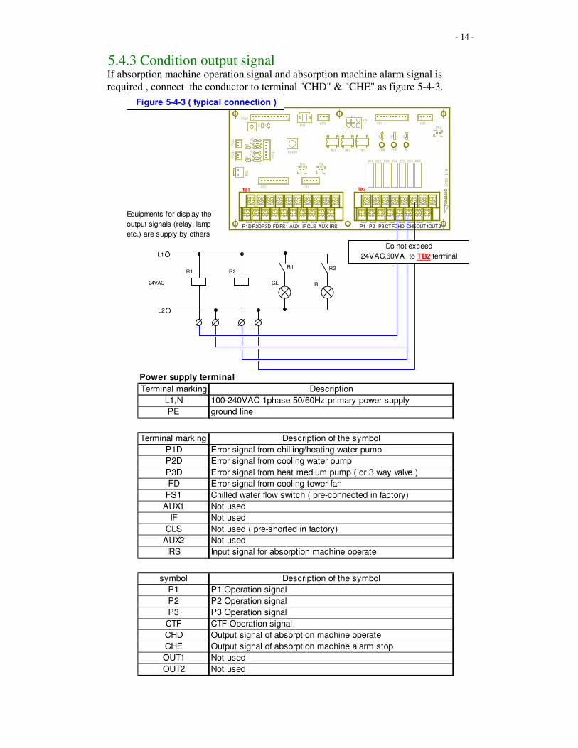
5.4.3 Condition output signal If absorption machine operation signal and absorption machine alarm signal is
required , connect the conductor to terminal "CHD" & "CHE" as figure 5-4-3.
PN7
TB1
1 2 3 4 5 6 7 8 9 10 1 2 3 4 5 6 7 8
TB2
RY1 RY2 RY3 RY4 RY5 RY6 RY7
51
CN3
1 10
CN4
1 4
CN6
DB1 DB2 DB3
1 3
CN5
1 12
1 9
CN2
12
12
16
PN1
PN11
PN12
CN11
PN2
R1
R2
R3
CNSP
L1
L2
L3
L4
R4
R7
R5
R6
R8
R9
PN4
1 2
1 2
PN6
1 2
PN5
RSTSW
SC05-I/
O
CHD CHE PL
P1DP2DP3D FD FS1 AUX IFCLS AUX IRS P1 P2 P3 CTFCHD CHEOUT1OUT2
TB1 TB2
Figure 5-4-3 ( typical connection )
R1
24VAC
L1
L2
R2R1 R2
GL RL
Equipments for display the
output signals (relay, lamp
etc.) are supply by others
Do not exceed
24VAC,60VA to TB2 terminal
Power supply terminal
Terminal marking Description
L1,N 100-240VAC 1phase 50/60Hz primary power supply
PE ground line
TB1 terminal
Terminal marking Description of the symbol
P1D Error signal from chilling/heating water pump
P2D Error signal from cooling water pump
P3D Error signal from heat medium pump ( or 3 way valve )
FD Error signal from cooling tower fan
FS1 Chilled water flow switch ( pre-connected in factory)
AUX1 Not used
IF Not used
CLS Not used ( pre-shorted in factory)
AUX2 Not used
IRS Input signal for absorption machine operate
TB2 terminal
symbol Description of the symbol
P1 P1 Operation signal
P2 P2 Operation signal
P3 P3 Operation signal
CTF CTF Operation signal
CHD Output signal of absorption machine operate
CHE Output signal of absorption machine alarm stop
OUT1 Not used
OUT2 Not used
- 15 -
6 Water Quality. 6.1 General. Water used in the chilled water circuit and cooling water circuit may cause corrosion
if not properly analysed and treated to maintain a passive condition. The cooling
water circuit is particularly vulnerable since in most cases, this is an open circuit thus
lending itself to scaling from precipitation of dissolved solids, and to growth of algae
and micro-organisms in the water. All have a detrimental effect on the function of
rejecting heat. If left unchecked, moreover, performance of the chiller will be affected
and a significant reduction in life expectancy could result. It is equally important to
consider that extreme health hazards may attend badly maintained cooling towers.
Correct and continuous water treatment is thus essential to the correct operation of the
chiller. Failure to provide and maintain in operation the necessary apparatus for water
treatment will immediately void the warranty applying to the absorption machine.
6.2 Water Quality Limits The following table describes the maximum limits of water contaminates within the
circuits of the chiller. Make-up water, exhibiting total dissolved solids no greater than
50ppm, with substantial “bleed-off”, would be necessary to achieve this result in the
cooling water circuit.
If such water quality in supply is not available under all circumstances, chemical
treatment is required to combat scaling. Chemicals to combat algae and micro-
organisms are in any event necessary. It is highly recommended that water treatment
specialists be retained prior to the initial commissioning of the plant and to provide an
ongoing program of chemicals and periodic inspections to ensure that the cooling
water circuit remains safe and compatible throughout.
- 16 -
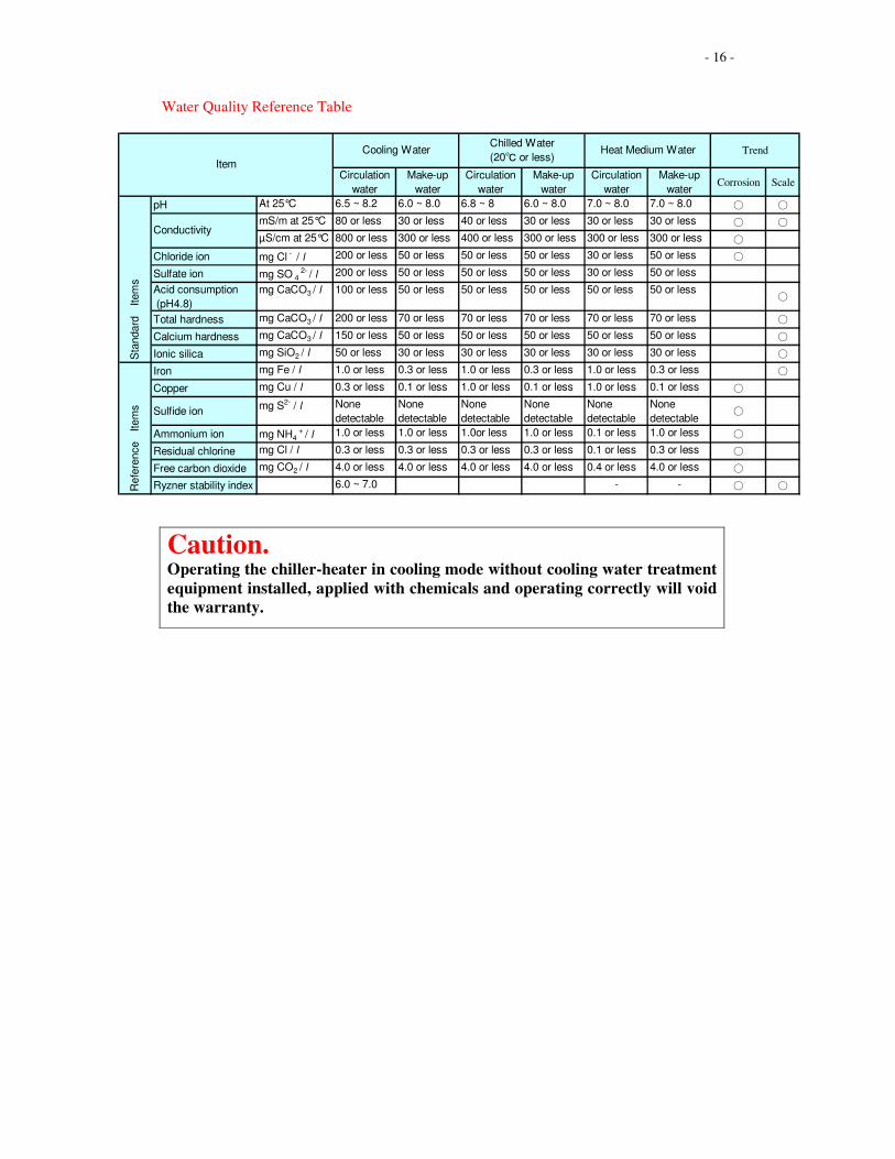
Water Quality Reference Table
Caution. Operating the chiller-heater in cooling mode without cooling water treatment
equipment installed, applied with chemicals and operating correctly will void
the warranty.
Circulation
water
Make-up
water
Circulation
water
Make-up
water
Circulation
water
Make-up
waterCorrosion Scale
pH At 25°C 6.5 ~ 8.2 6.0 ~ 8.0 6.8 ~ 8 6.0 ~ 8.0 7.0 ~ 8.0 7.0 ~ 8.0 ○ ○
mS/m at 25°C 80 or less 30 or less 40 or less 30 or less 30 or less 30 or less ○ ○
µS/cm at 25°C 800 or less 300 or less 400 or less 300 or less 300 or less 300 or less ○
Chloride ion mg Cl - / l 200 or less 50 or less 50 or less 50 or less 30 or less 50 or less ○
Sulfate ion mg SO 4 2- / l 200 or less 50 or less 50 or less 50 or less 30 or less 50 or less
Acid consumption
(pH4.8)
mg CaCO3 / l 100 or less 50 or less 50 or less 50 or less 50 or less 50 or less○
Total hardness mg CaCO3 / l 200 or less 70 or less 70 or less 70 or less 70 or less 70 or less ○
Calcium hardness mg CaCO3 / l 150 or less 50 or less 50 or less 50 or less 50 or less 50 or less ○
Ionic silica mg SiO2 / l 50 or less 30 or less 30 or less 30 or less 30 or less 30 or less ○
Iron mg Fe / l 1.0 or less 0.3 or less 1.0 or less 0.3 or less 1.0 or less 0.3 or less ○
Copper mg Cu / l 0.3 or less 0.1 or less 1.0 or less 0.1 or less 1.0 or less 0.1 or less ○
Sulfide ionmg S2- / l None
detectable
None
detectable
None
detectable
None
detectable
None
detectable
None
detectable○
Ammonium ion mg NH4 + / l 1.0 or less 1.0 or less 1.0or less 1.0 or less 0.1 or less 1.0 or less ○
Residual chlorine mg Cl / l 0.3 or less 0.3 or less 0.3 or less 0.3 or less 0.1 or less 0.3 or less ○
Free carbon dioxide mg CO2 / l 4.0 or less 4.0 or less 4.0 or less 4.0 or less 0.4 or less 4.0 or less ○
Ryzner stability index 6.0 ~ 7.0 - - ○ ○
Trend
Sta
ndard
Item
s
Conductivity
Refe
rence
Item
s
Cooling WaterChilled Water
(20℃ or less)Heat Medium Water
Item
- 17 -
7 Commissioning Request. 7.1 General After the absorption chiller has been installed, piped, flushed, leak tested and
electrically wired as described in these instructions, and in full compliance with all
pertinent safety codes, the Yazaki authorised distributor must be contacted to arrange
supervision of the initial test-run and plant commissioning. It is essential that
personnel representing all trade disciplines involved in the installation be on site on
the day of start-up to cater for any final adjustment and alterations necessary to allow
the chiller and the system generally to function correctly.
- 18 -
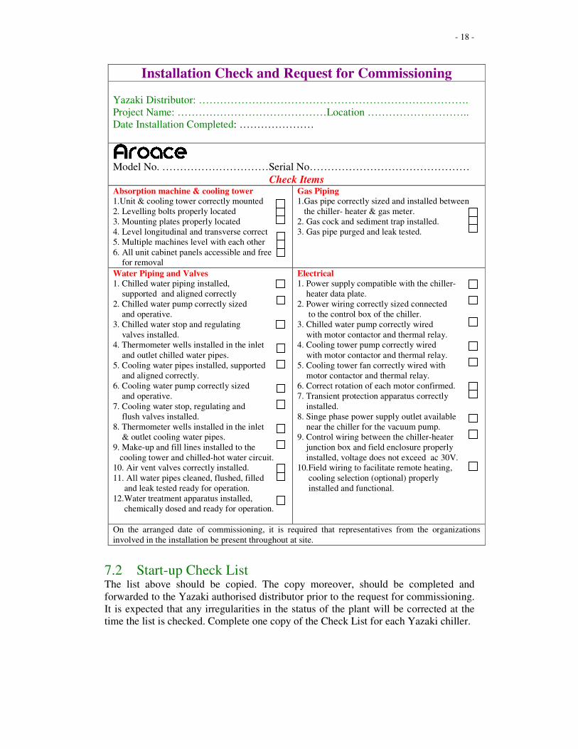
Installation Check and Request for Commissioning
Yazaki Distributor: ………………………………………………………………….
Project Name: ……………………………………Location ………………………..
Date Installation Completed: …………………
Model No. …………………………Serial No………………………………………
Check Items Absorption machine & cooling tower
1.Unit & cooling tower correctly mounted
2. Levelling bolts properly located
3. Mounting plates properly located
4. Level longitudinal and transverse correct
5. Multiple machines level with each other
6. All unit cabinet panels accessible and free
for removal
Gas Piping
1.Gas pipe correctly sized and installed between
the chiller- heater & gas meter.
2. Gas cock and sediment trap installed.
3. Gas pipe purged and leak tested.
Water Piping and Valves
1. Chilled water piping installed,
supported and aligned correctly
2. Chilled water pump correctly sized
and operative.
3. Chilled water stop and regulating
valves installed.
4. Thermometer wells installed in the inlet
and outlet chilled water pipes.
5. Cooling water pipes installed, supported
and aligned correctly.
6. Cooling water pump correctly sized
and operative.
7. Cooling water stop, regulating and
flush valves installed.
8. Thermometer wells installed in the inlet
& outlet cooling water pipes.
9. Make-up and fill lines installed to the
cooling tower and chilled-hot water circuit.
10. Air vent valves correctly installed.
11. All water pipes cleaned, flushed, filled
and leak tested ready for operation.
12.Water treatment apparatus installed,
chemically dosed and ready for operation.
Electrical
1. Power supply compatible with the chiller-
heater data plate.
2. Power wiring correctly sized connected
to the control box of the chiller.
3. Chilled water pump correctly wired
with motor contactor and thermal relay.
4. Cooling tower pump correctly wired
with motor contactor and thermal relay.
5. Cooling tower fan correctly wired with
motor contactor and thermal relay.
6. Correct rotation of each motor confirmed.
7. Transient protection apparatus correctly
installed.
8. Singe phase power supply outlet available
near the chiller for the vacuum pump.
9. Control wiring between the chiller-heater
junction box and field enclosure properly
installed, voltage does not exceed ac 30V.
10.Field wiring to facilitate remote heating,
cooling selection (optional) properly
installed and functional.
On the arranged date of commissioning, it is required that representatives from the organizations
involved in the installation be present throughout at site.
7.2 Start-up Check List The list above should be copied. The copy moreover, should be completed and
forwarded to the Yazaki authorised distributor prior to the request for commissioning.
It is expected that any irregularities in the status of the plant will be corrected at the
time the list is checked. Complete one copy of the Check List for each Yazaki chiller.