Embed Size (px)
Citation preview

WFC- SC
Chiller
1 Specifications
WFC-SC5
Version 8-1

1
Contents
Page
1. Specifications 1.1 Model Designation-------------------------------------- 2
1.2 Multiple Module ---------------------------------------- 2
1.3 Specification Table-------------------------------------- 3
1.4 External Dimensions --------------- 4
2. Performance Characteristics 2.1 Cooling Performance ---------------- 5
2.2 De-rating factor --------------- 6
2.3 Noise Criteria ---------------------------- 7
3. Principle & Structure 3.1 General ------------------------- 8
3.2 Cooling Cycle ------------------------- 9
3.3 Heat Balance ------------------------- 9
4. Component Identification & Function 4.1 Chiller assembly ---------------- 10
4.2 Component Description ---------------- 13

2
1. Specification
1.1 Model Designation
W F C - S C 5
Water Fired Chiller
Series
Type
C: Chiller
Cooling Capacity RT
1.2 Multiple Module Combination
Model Rt Note
WFC-SC5 5 Cooling only

3
1.3 Specification Table
Item
WFC-SC5
Cooling capacity kW 17.6
Inlet °C 12.5 Temperature
(cooling) Outlet °C 7.0
Evaporator pressure loss kPa 52.6
Maximum operating pressure kPa 588
l/s 0.77 Flow rate
㎥/h 2.77
Chilled water
Water retention volume l 8
Heat rejection kW 42.7
Inlet °C 31.0 Temperature
Outlet °C 35.0
Absorber/condenser pressure loss kPa 38.3
Maximum operating pressure kPa 588
l/s 2.55 Flow rate
㎥/h 9.18
Cooling water *1
Water retention volume l. 37 Heat input kW 25.1
Inlet °C 88 Outlet °C 83 Temperature
Inlet Range °C 70 - 95 Generator pressure loss kPa 77.0 Maximum operating pressure kPa 588
l/s 1.20 Flow rate
㎥/h 4.32
Heat medium
Water retention volume l. 10 Voltage V AC100-240 Frequency Hz 50/60 Power supply
Phase ph 1
Electrical
Consumption *1 W 48
Control On - Off Width mm 594 Depth mm 744 Dimensions
Height *2 mm 1,736(1,816) Dry kg 365
Weight Operating kg 420 Chilled water 32A Cooling water 40A
Piping
Diameter (A) Heat medium 40A
Cabinet and finish
Weatherproof cabinet suitable for indoor or outdoor
application comprising silver metallic pre-painted
hot dip zinc coated sheet steel exterior panels.
*1.Power consumption of Chiller only. (Excluding circulating pumps and cooling tower fan)
*2.Dimension in ( ) includes fixed plate and eye bolt.
*3.Specification are subject to change without prior notice.
*4.The flow rate of Chilled-hot water and Cooling water must be stable.
The allowable flow rate range are Chilled- water: 80 to 120% of nominal, Cooling water: 100 to 120% of nominal.

1.4 External Dimensions
5
0
5
10
15
20
25
30
35
40
65 70 75 80 85 90 95 100
Heat Medium Inlet Temperature °C
Heat
Med
ium
In
pu
t(kW
)
Cooling water inlet temperature
27°C
29.5°C
31°C
32°C
Standard point. Chilled w ater
outlet 7°C
0
5
10
15
20
25
65 70 75 80 85 90 95 100
Heat Medium Inlet Temperature °C
Co
olin
g C
ap
acit
y (
kW
)
Cooling water inlet temperature
27°C
29.5°C
31°C
32°C Standard point. Chilled
water outlet 7°C
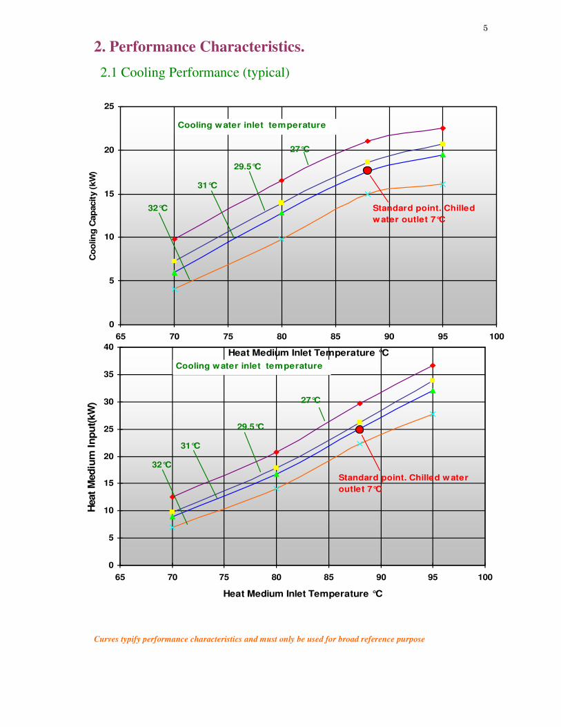
2. Performance Characteristics.
2.1 Cooling Performance (typical)
Curves typify performance characteristics and must only be used for broad reference purpose

6
0.6
0.7
0.8
0.9
1
1.1
0 20 40 60 80 100 120
Heat Medium Flow Ratio (%)
De-r
ati
ng
facto
r
Standard point. Chilled
water outlet 7°C
2.2 De-rating factor (typical)
Note: All other parameters of flow and temperature are considered standard.
Curves typify performance characteristics and must only be used for broad reference purpose

7
1.0
1.5
m 1.0
1.5
m
2.3 WFC-SC5 Noise Criteria

8
3. Principle & Structure
3.1 General
The WFC-SC5 absorption chiller is limited to chilling mode.
3.2 Cooling Cycle.
Referring to the schematic of the cooling cycle as shown in figure1, lithium bromide
solution (Dilute Solution) is pumped to the generator (GE) by the solution pump (SP)
where it is heated to boiling point by the circulating heat medium. Refrigerant vapor
(water vapor) is liberated from solution and flows to the condenser (CON) where it is
condensed to a liquid state by rejection of heat to the cooling water from the cooling
tower circulating through the condenser coil.
Because partial separation of the lithium bromide and the water in solution has occurred
in the process of boiling in the (GE), an increase in concentration takes place and the
resultant solution is termed (Concentrate Solution). Accordingly, the concentrate
solution flows from (GE) to the heat exchanger (HE), imparting heat to the dilute
solution, before arriving at the absorber (ABS) to flow over the surface of the absorber
coil.
Since cooling water from the cooling tower is circulating through the absorber coil, a
comparatively low vapor pressure is created due to the concentration of the lithium
solution, and this is the environment which refrigerant liquid from the condenser
encounters as it flows over the coil in the evaporator (EVA). The concentrate solution
absorbs refrigerant vapor from the evaporator as the liquid refrigerant changes phase
deriving heat of vaporization from the chilled water circulating through the evaporator
coil. This results in the production of chilled water.
The concentrate solution returns to a diluted state as refrigerant vapor is absorbed. In its
relatively cool condition, it is collected in the (ABS)/(EVA) sump and thereafter forced
by (SP) through the (HE) collecting heat from the concentrate solution before returning
to the (GE) for boiling again to repeat the cycle.

9
3.3 Heat Balance (Cooling Cycle)

10
4. Component Identification and Function
4.1 Chiller Assembly (WFC-SC5)
Parts and components are identified in the following.

11

12
13
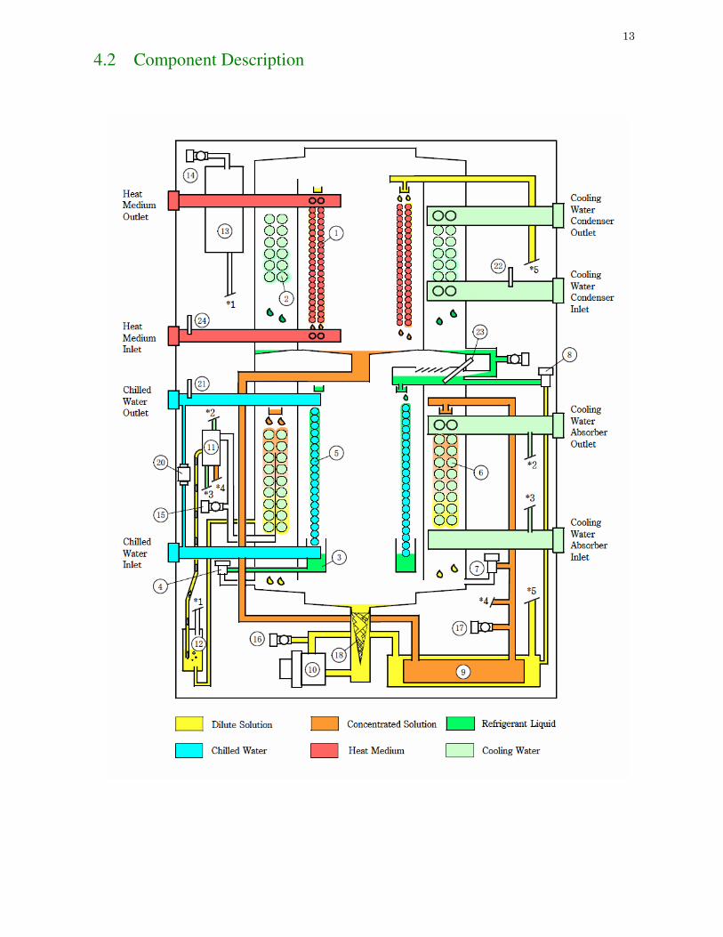
4.2 Component Description

14
No. Component Description 1 Generator (GE) Boils dilute LiBr solution to separate refrigerant from the
absorbent
2 Condenser (CON) Condenses refrigerant vapour to provide liquid refrigerant.
3 Refrigerant storage tray
(RST)
For accumulating liquid refrigerant for best suited solution
density.
4 Refrigerant blow valve
(RBV)
To blow refrigerant liquid stored in Refrigerant storage when
shutdown. Also RBV will open when LT is 3℃ or less and
cooling water temp 20℃ or less to prevent from solution
condensing.
5 Evaporator (EVA) Heat of evaporation or condensation from the refrigerant is
extracted from, or transferred to, the water flowing through the
EVA coil
6 Absorber (ABS) As refrigerant vapor is absorbed by the LiBr solution, heat of
absorption is transferred to the cooling water flowing through the
ABS coil.
7 Solution bypass valve
(SV9)
In the event the EVA, or cooling water temperatures fall to a
predetermined level, SV9 will open to reduce the flow of LiBr
solution to the ABS
8 Refrigerant freeze
protection valve (SV1)
If the operation of SV9 does not arrest the fall in temperature of
the EVA, SV1 valve will open at 1°C to allow dilute solution to
enter the evaporator.
9 Heat exchanger (HE) Heat exchange between the cool dilute and hot concentrate LiBr
solution is facilitated by HE.
10 Solution pump (SP) Dilute LiBr solution is transferred from the ABS to the GE by
the SP.
11 Auxiliary absorber Non-condensable gases are gathered from the ABS by the
auxiliary absorber.
12 Non-condensable gas
separator
Gases gathered by the auxiliary absorber are separated from
dilute solution and transported to the storage tank GT.
13 Non-condensable gas
storage tank (GT)
GT retains non-condensable gases accumulating in the
absorption circuit.
14 Non-condensable storage
service valve (A)
Removal of non-condensable gases from the GT is facilitated by
valve (A).
15 ABS service valve (B) Vacuum service of the ABS/EVA areas of the chiller is afforded
by valve (B)
16 Dilute solution sampling
valve
Dilute LiBr solution circuit is accessed by the dilute solution
service valve.
17 Concentrate solution
sampling valve
Concentrate LiBr solution circuit is accessed by the concentrate
solution service valve.
18 Strainer Solution drawn from the absorber is strained before entering the
solution pump.
19 Control box (CB) All operation of the chiller and interface with external controls is
provided by the CB
20 Flow switch (FS) If the chilled water flow rate falls to less than 80% of standard,
the operation of the chiller will cease.
21 Thermistor (WTO) The chilled water outlet temperature is controlled by WTO =-
see section 4 Electrical & Maintenance
22 Thermistor (CTI) The chiller operation is responsive to cooling water temperature
monitored by CTI – see section 4 Electrical & Maintenance
23 Thermistor (LT) Operation of the chiller is responsive to the EVA temperature
monitored by LT – see section 4 Electrical & Maintenance.
24 Thermistor (HWT) Operation of the chiller is responsive to the inlet heat medium
temperature monitored by HWT – see section 4 Electrical &
Maintenance.